ABB WICB WiCB User Manual
ABB WiCB
UserManual.wiki
>
ABB
>
WICB User Manual
User Manual
Navigation menu
Upload a User Manual
Namespaces
Wiki Guide
HTML
PDF
Info
Views
User Manual
Discussion / Help
Navigation


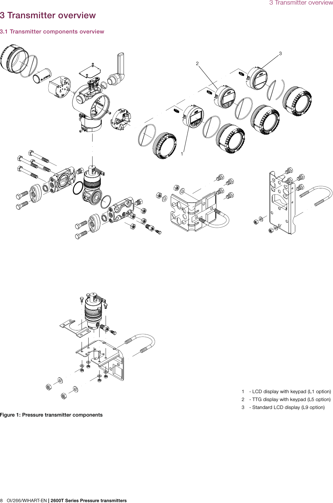

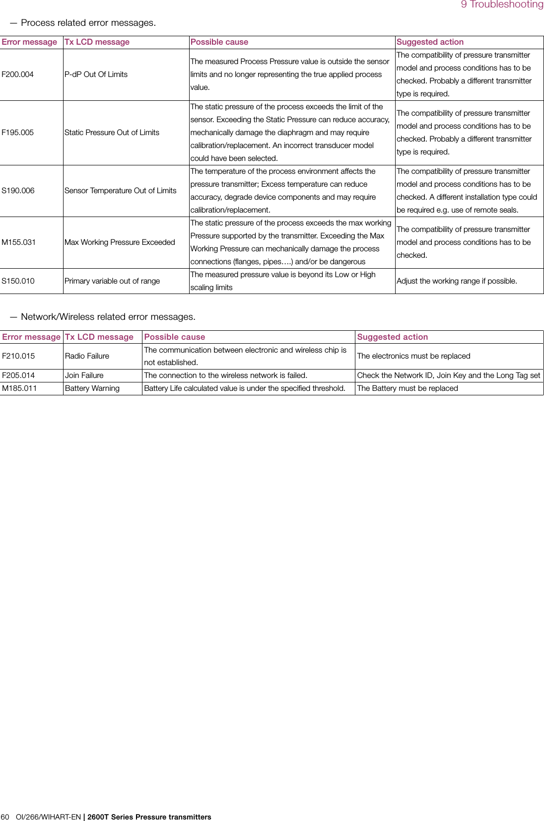
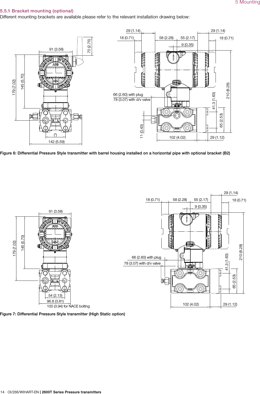
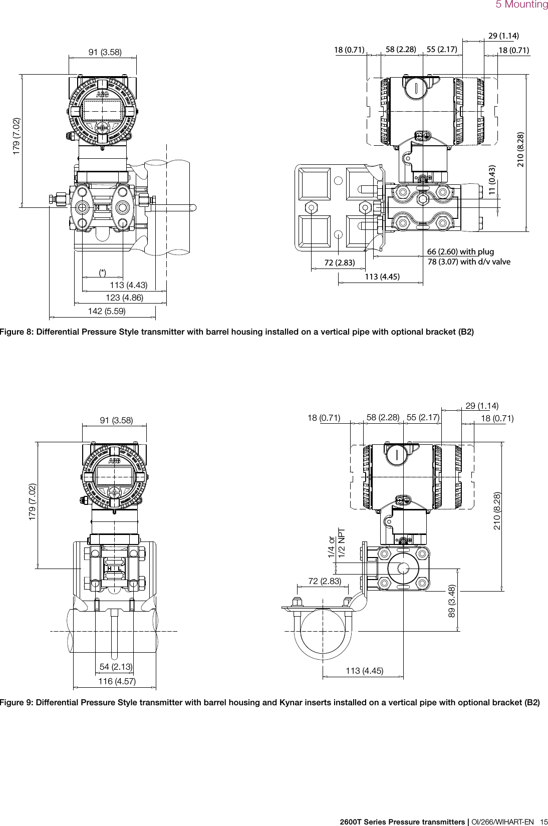
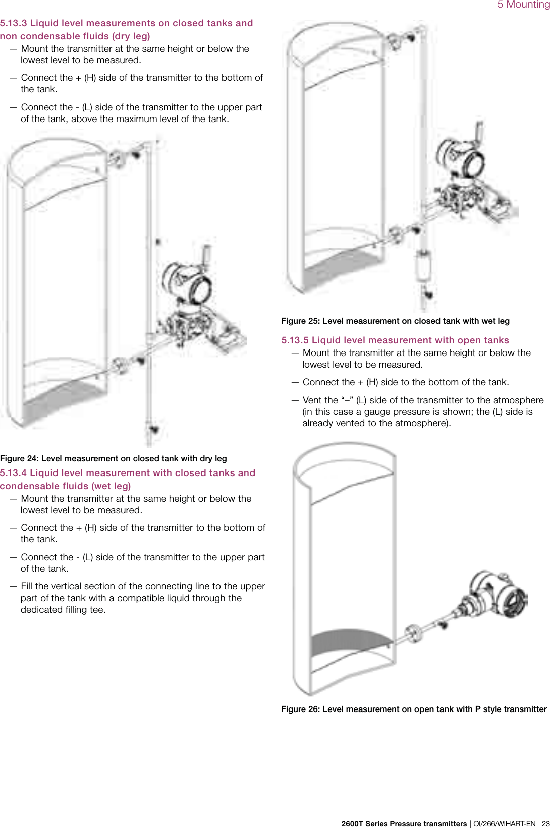
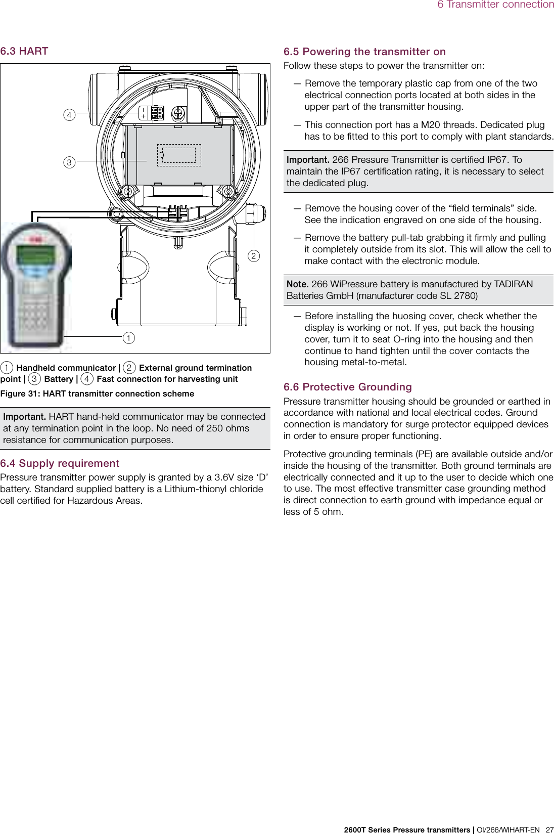
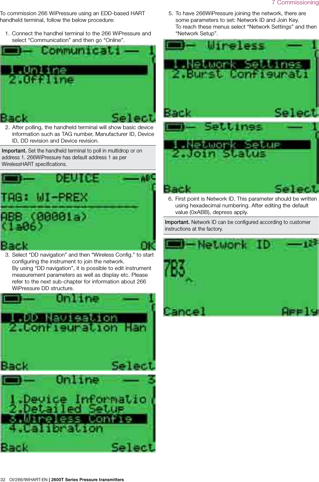
![2600T Series Pressure transmitters | OI/266/WIHART-EN 135 MountingFigure 4: 266 nameplate with PED dataLocal keys below labelPRODUCT CODESEAL-H SEAL-LSPEC.REQUESTLRL/URLSPAN LIMITSPOWER SUPPLY OUTPUT SIGNAL ABB S.p.A. Made in Italy TS PSSERIAL\NUMBERSENSOR DIAPH.-FILLFLANGE/CONN.-GASKET/SH DIAPH.-FILLL DIAPH.-FILLSEALHW Rev. MD:PED:MWP/OVPImportant. In case of a High Static differential pressure transmitter, please notice that the Vent/Drain valves can be configured only on the process axis (V1).5.4.2 Devices with PS ≤200 barDevices with a permissible pressure PS ≤200 bar correspond to article 3 paragraph (3). They have not been subject to a conformity validation. These instruments were designed and manufactured acc. to SEP Sound Engineering Practices. 5.5 Mounting a DP sensor transmitter (266DS/266DR) The pressure transmitter model 266DS can be mounted directly on the manifold. A mounting bracket for wall or pipe mounting (2” pipe) is also available as an accessory. For model 266DR always mounting brackets should be used. Ideally, the pressure transmitter should be mounted in a vertical position to prevent subsequent zero shifts.Important. If the transmitter is installed inclined with respect to the vertical, the filling liquid exerts hydrostatic pressure on the measuring diaphragm, resulting in a zero shift. In such an event, the zero point can be corrected via the zero push-button or via the “set PV to zero” command. Please refer to the [configuration section] for further details. For transmitters without diaphragm seals, please read the following considerations on the Vent/Drain.Attention − Potential damage to transmitter. In case of a High Static differential pressure transmitter (266DSH.x.H) please always open the equalization valve of the manifold (if installed) before applying pressure to the transmitter. High Static pressure can damage the sensor causing a zero shift and a serious decrease of the total performance in terms of accuracy. In this case, please perform a full sensor trim.It is important to mount the transmitter and to lay the process Figure 5: Drain/vent valves configuration (respectively V1, V2, V3)5.4 Pressure Equipment Directive (PED) (97/23/CE)5.4.1 Devices with PS >200Devices with a permissible pressure PS >200 bar have been subject to a conformity validation. The data label includes the following specifications:piping so that gas bubbles, when measuring liquids, or condensate when measuring gases, will flow back to the process and not enter the transmitter measuring chamber. Optional Vent/drain valves (code V1/V2/V3) on the transmitter are located on the sensor flanges. The transmitter has to be positioned so that these drain/vent valves will be located higher than the taps on liquid service in order to allow the venting of entrapped gas or below the taps on gas service in order to allow the air to vent off or condensate to drain off. For safety reasons, take care of the drain/vent valves position so that when the process fluid is removed during the drain/vent operation it is directed down and away from technicians. It is recommended to mount the transmitter to prevent this possible source of damage for unskilled operators.](https://usermanual.wiki/ABB/WICB/User-Guide-2536030-Page-13.png)
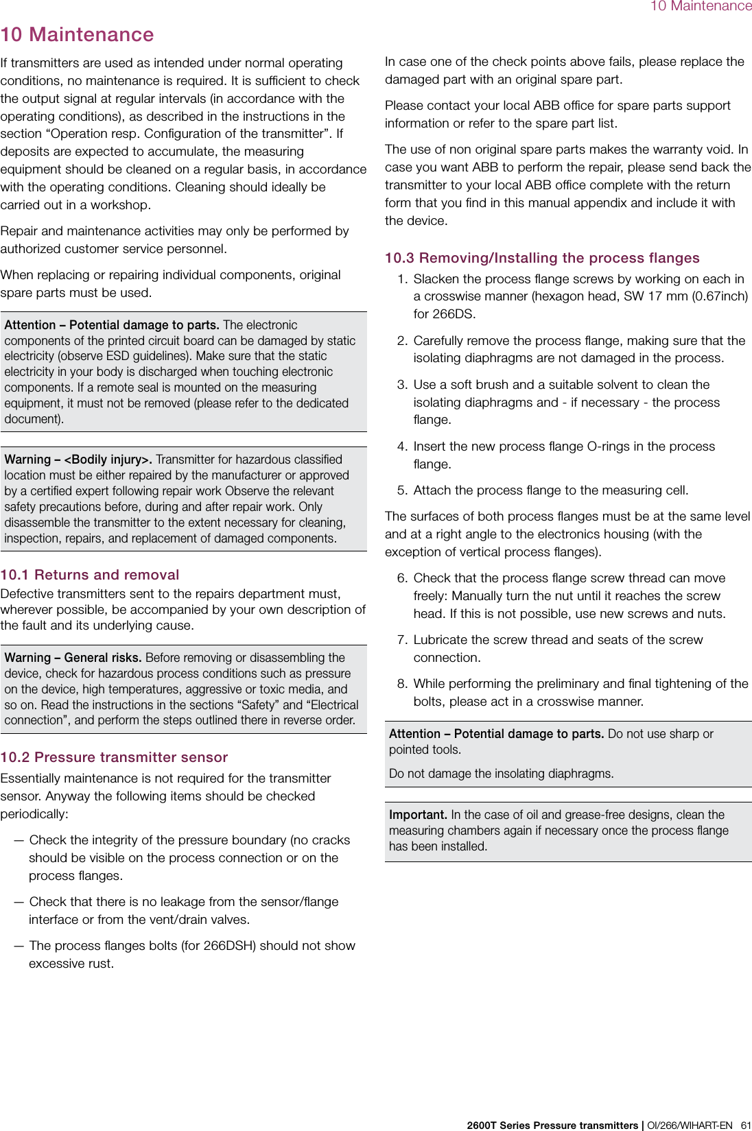
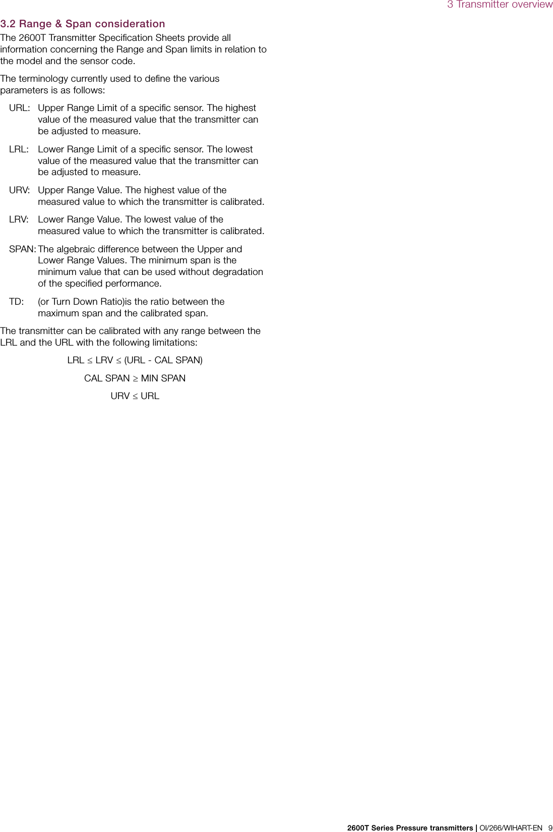
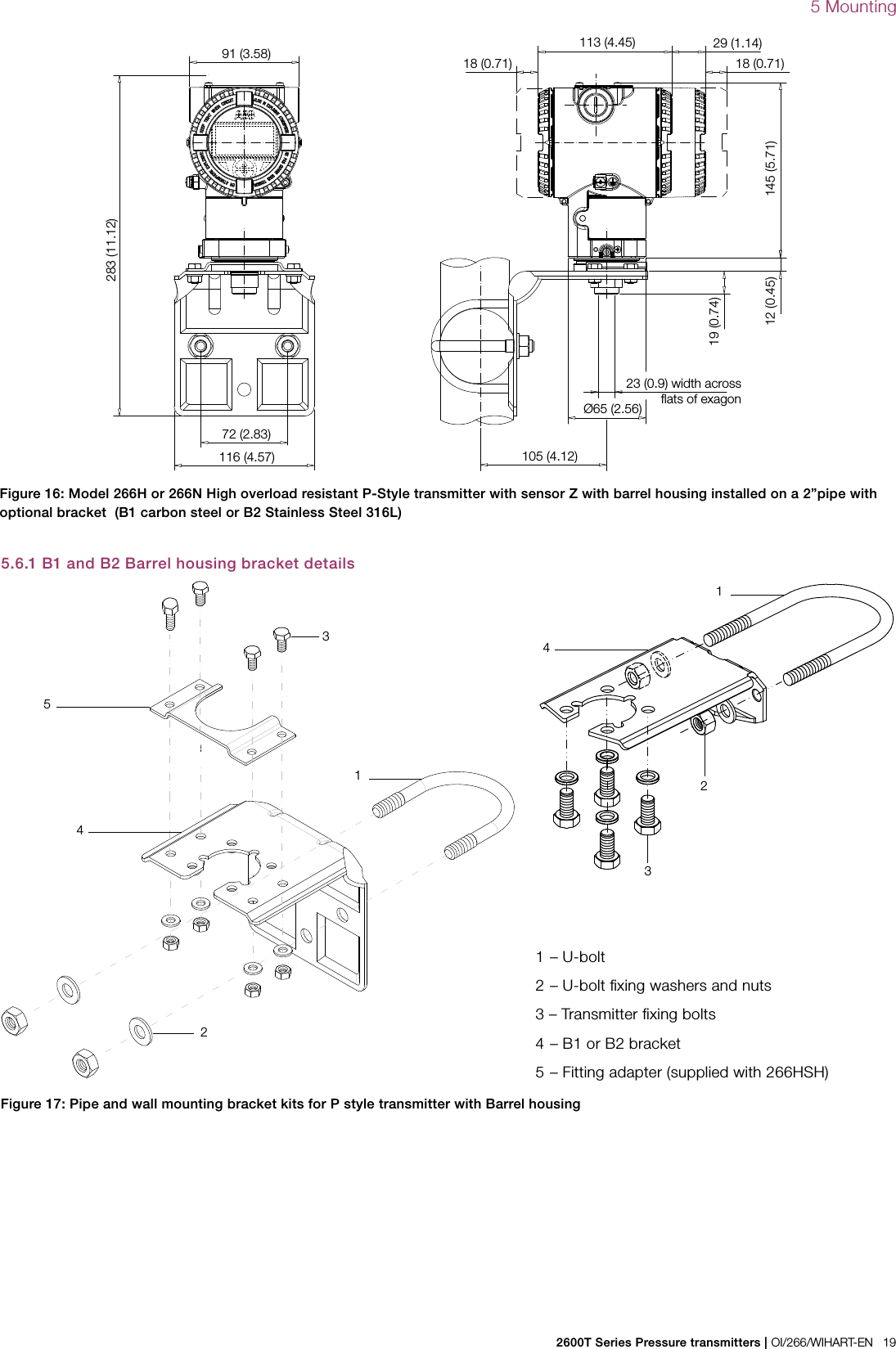
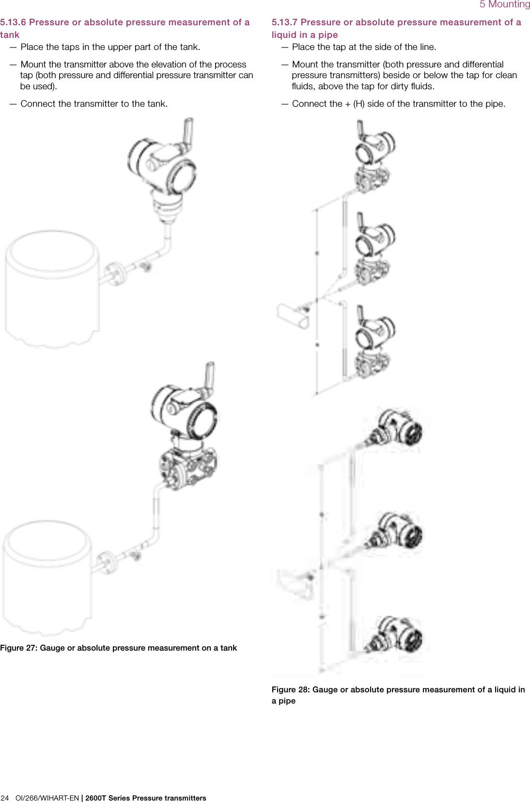
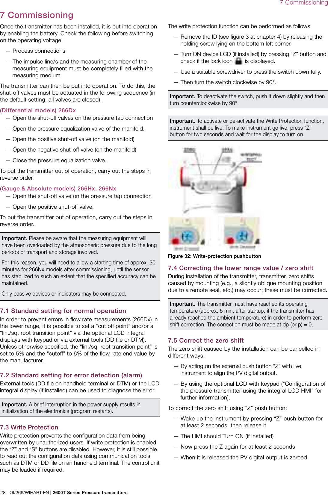
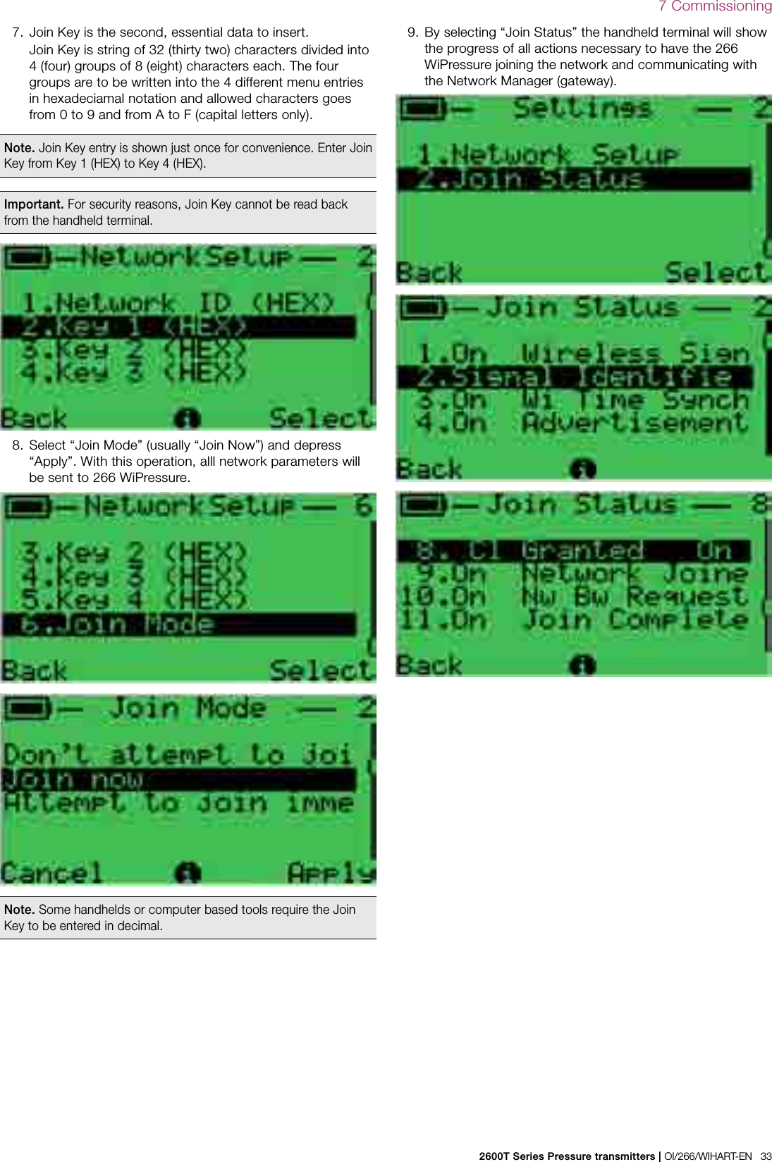
![18 OI/266/WIHART-EN | 2600T Series Pressure transmitters5 Mounting5.6 Mounting a P style pressure transmitter (266H and 266N)The pressure transmitter can be mounted directly on the manifold. A mounting bracket for wall or pipe mounting (2” pipe) is also available as an accessory.Ideally, the pressure transmitter should be mounted in a vertical position to prevent subsequent zero shifts.Figure 14: Model 266H or 266N High overload resistant P-Style transmitter with 1/2-14 NPT male process connection and barrel housing installed on a 2”pipe with optional bracket (B1 carbon steel or B2 Stainless Steel 316L)Important. If the transmitter is installed inclined with respect to the vertical, the filling liquid exerts hydrostatic pressure on the measuring diaphragm, resulting in a zero shift. In such an event, the zero point can be corrected via the zero push-button or via the “set PV to zero” command. Please refer to the [configuration section] for further details. For transmitters without diaphragm seals the Vent / Drain considerations below should be taken into consideration.91 (3.58)72 (2.83)18 (0.71)113 (4.45) 29 (1.14)18 (0.71)145 (5.71)18 (0.71)16 (0.63)36 (1.42)108 (4.25) 49 (1.93)19 (0.75)32 (1.26) width acrossflats of exagon18 (0.71)113 (4.45) 29 (1.14)18 (0.71)145 (5.71)91 (3.58)18 (0.71)16 (0.63)108 (4.25)72 (2.83)39 (1.54)49 (1.93)54 (2.13)1/2 - 14 NPT32 (1.26) width acrossflats of exagonFigure 15: Model 266H or 266N High overload resistant P-Style transmitter with 1/2-14 NPT female process connection and barrel housing installed on a 2”pipe with optional bracket (B1 carbon steel or B2 Stainless Steel 316L)](https://usermanual.wiki/ABB/WICB/User-Guide-2536030-Page-18.png)
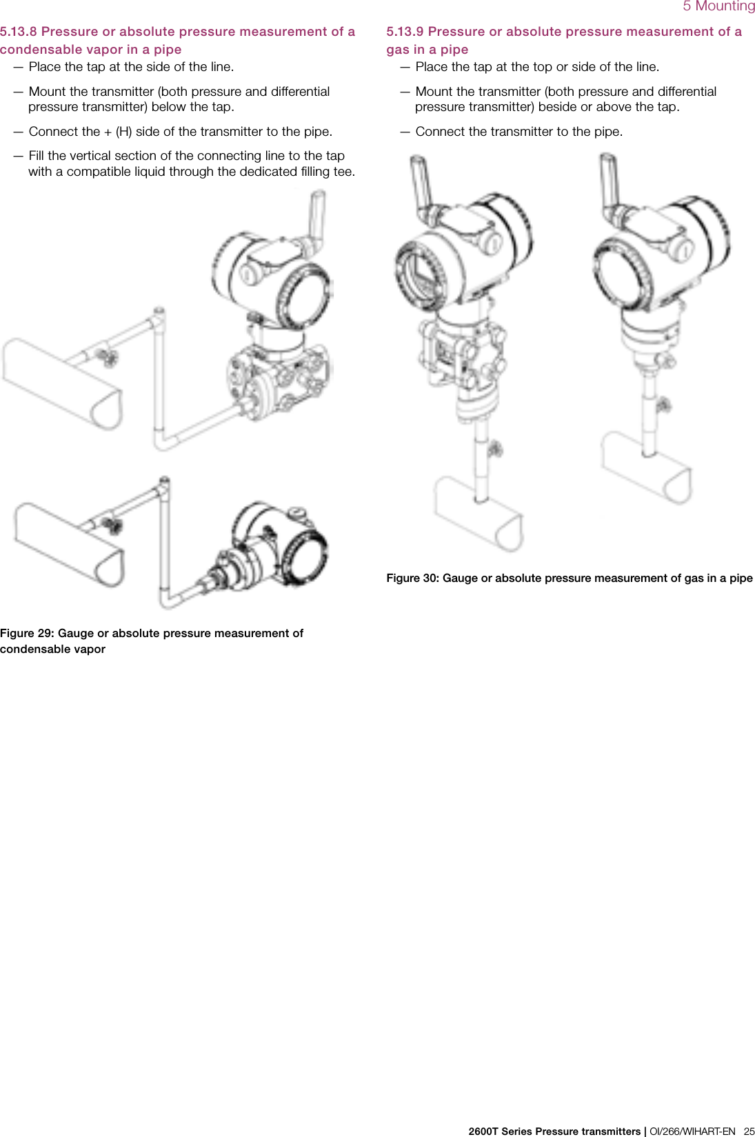
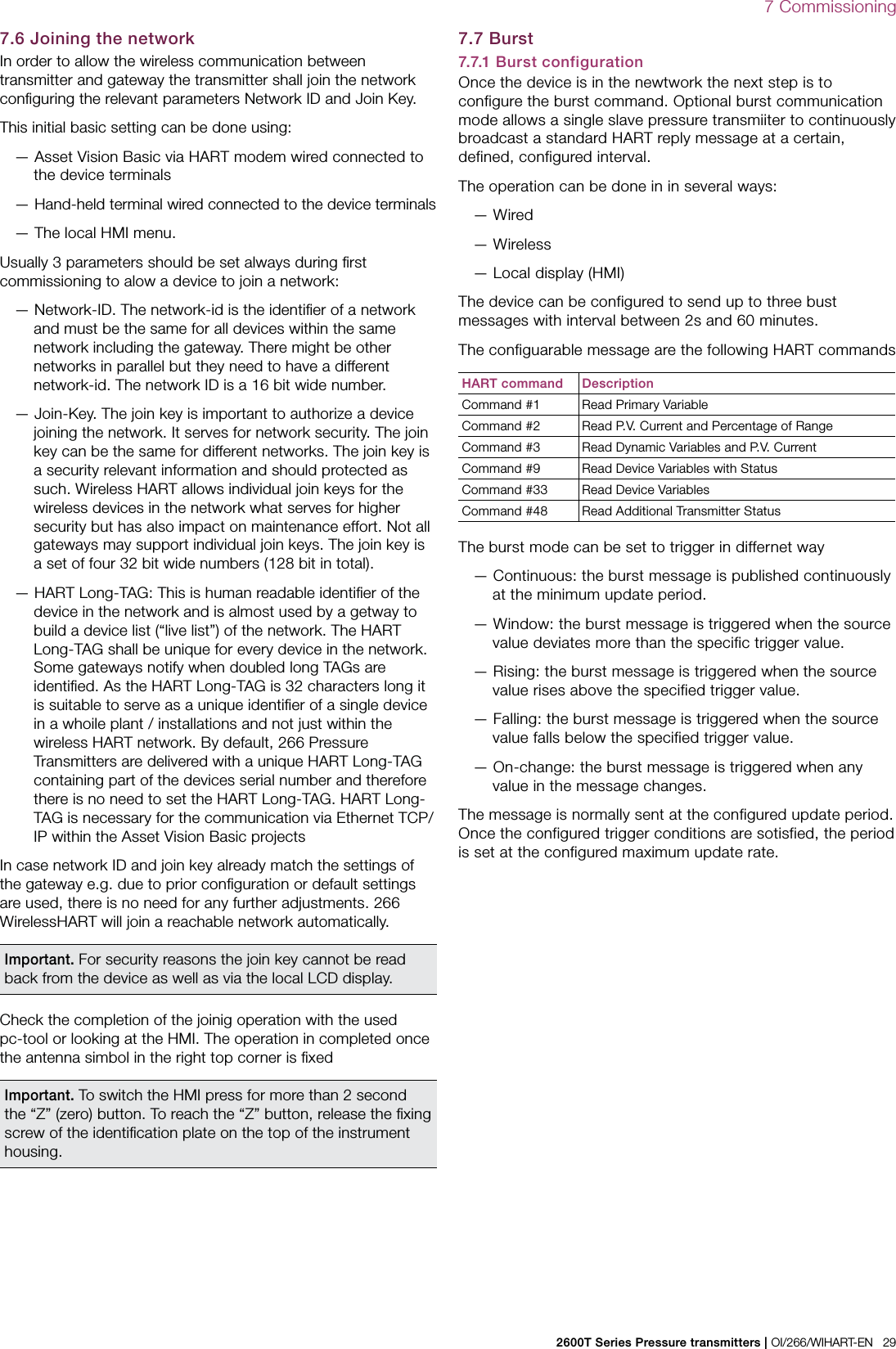

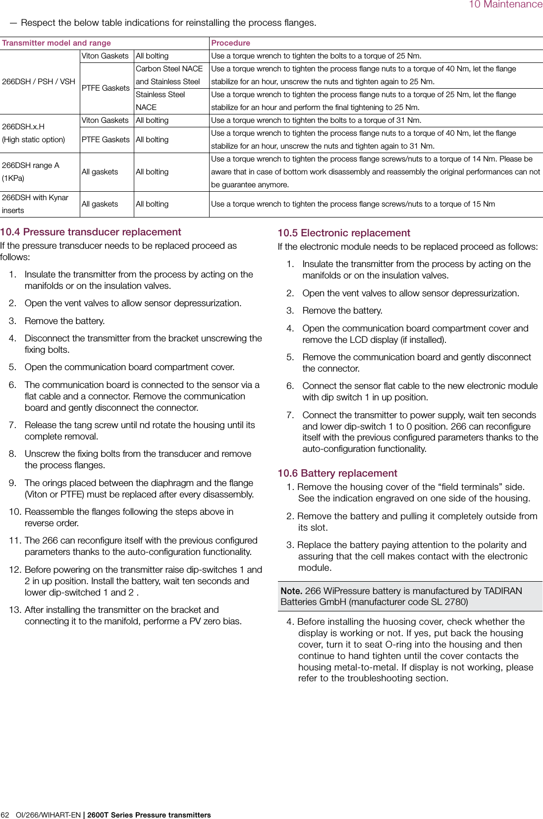
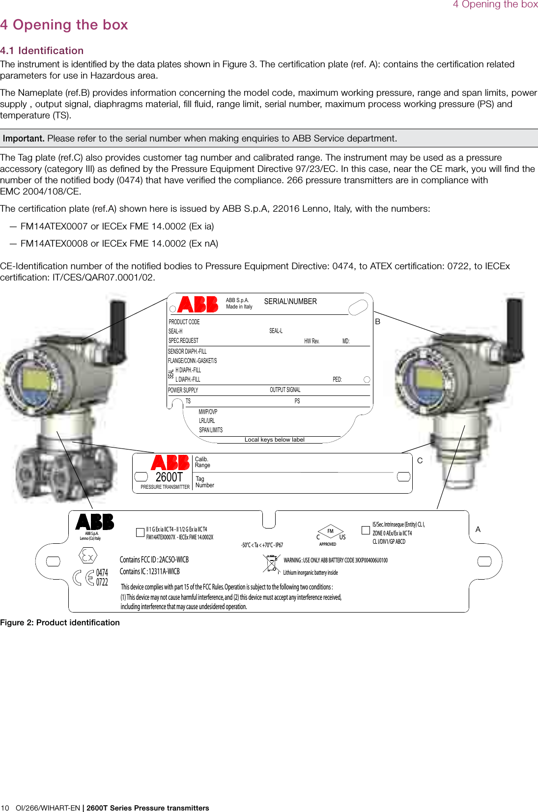
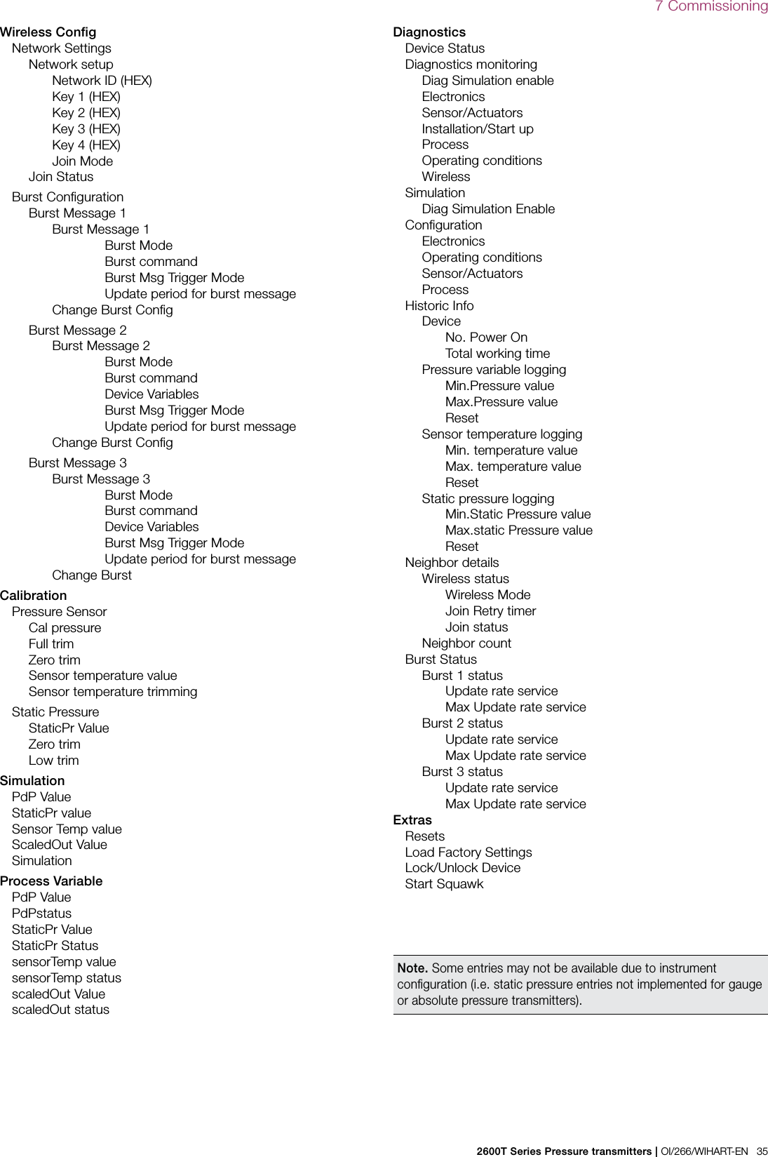
![34 OI/266/WIHART-EN | 2600T Series Pressure transmitters7 Commissioning7.8.1 EDD structure for 266 WiPressureDevice information Device Manufactorer Model Device Serial No Device revision HART Revision Device Profile Additional Device Revision Hardware Revision Software Revision Measurement Point Address Write Protection Communication tag Date Final Assembly Num Descriptor Message Additional information Long tag Sensor type Sensor revision Read Sensor Sl number Detailed Setup General Local Operations Sensor Set-up P-dP Sensor Sensor Type Upper Sensor Limit Lower Sensor Limit Minimum span Static Pressure Sensor Upper Sensor Limit Lower Sensor Limit Minimum span Operational limit Max Temperature limit Min Temperature limit Max Working Pressure Unit Temperature Unit Static Pressure unit Pressure Polarity Pressure input [Direct] Sensor materials Basic Sensor materials Diaphragm material Filling Fluid Process Connection High Connection type Flange Material O-Ring Material Blanking Plug Process Connection Low Connection type Flange Material O-Ring Material Blanking Plug P-dP Process variable Measured value PdP Value PV % range Scaling Value Input Unit PV LRV PV URV Process Pressure Rerange PV Bias PdP Value Set PV Val Set PV to Zero Bias Value PV Bias Reset Parallel Shift Parallel Shift Transfer Function Transfer Function Square Root Setting Lin.Square root Point [%] Cut Off Output Scaling Unit Custom Unit Lower range Value Upper range Value Hart Mapping PV is SV is TV is QV is Change SV mapping Change TV mapping Change QV mapping Display General Display Revision Contrast Language Display Setting Display Mode Line 1 view Line 2 view Bargraph view](https://usermanual.wiki/ABB/WICB/User-Guide-2536030-Page-34.png)
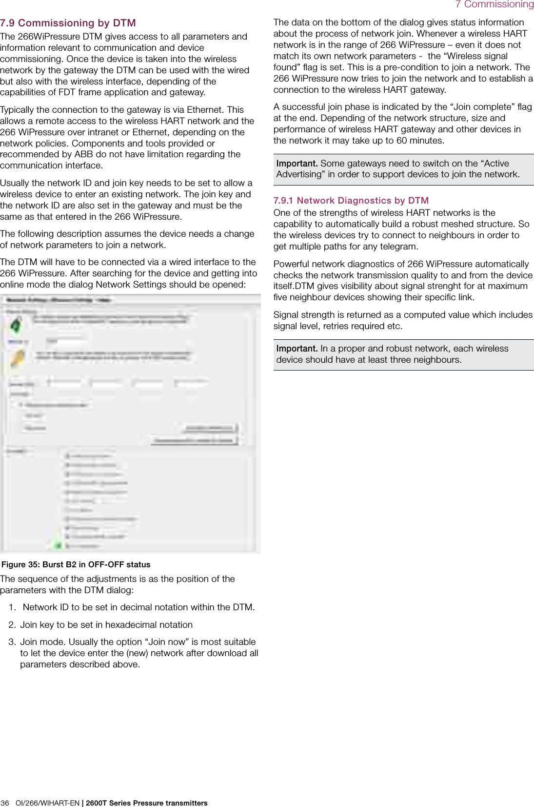
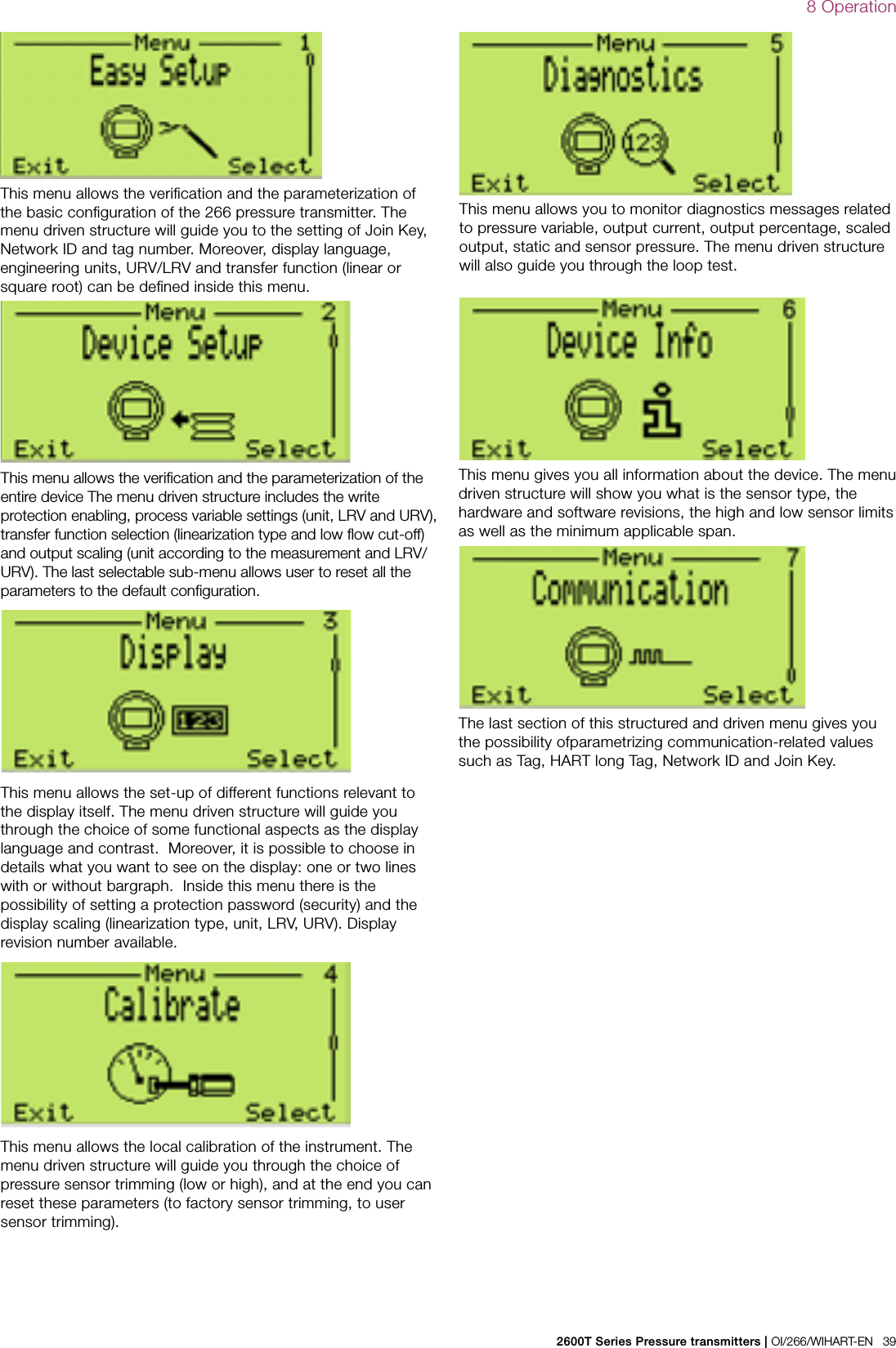
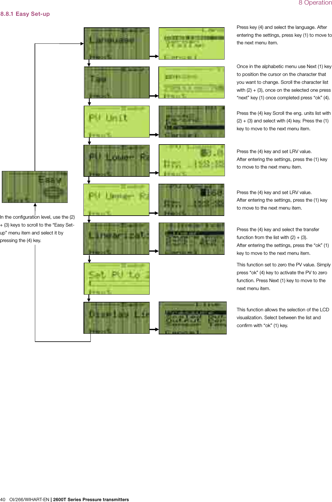
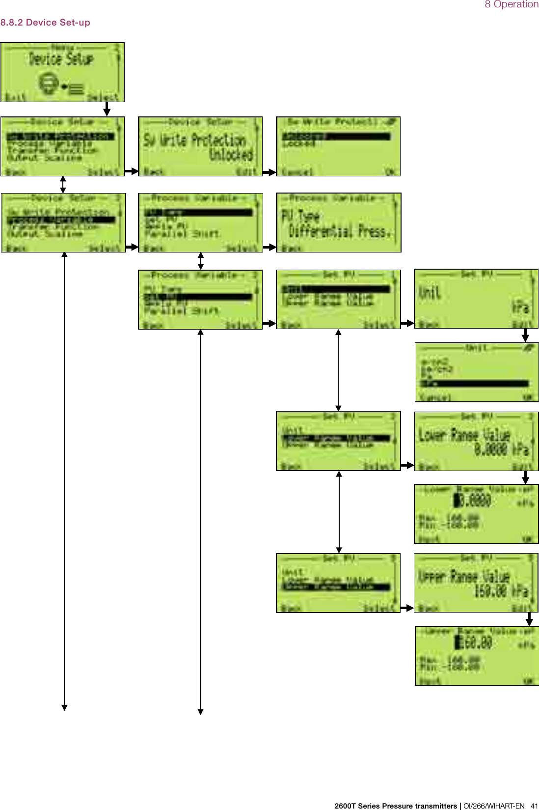
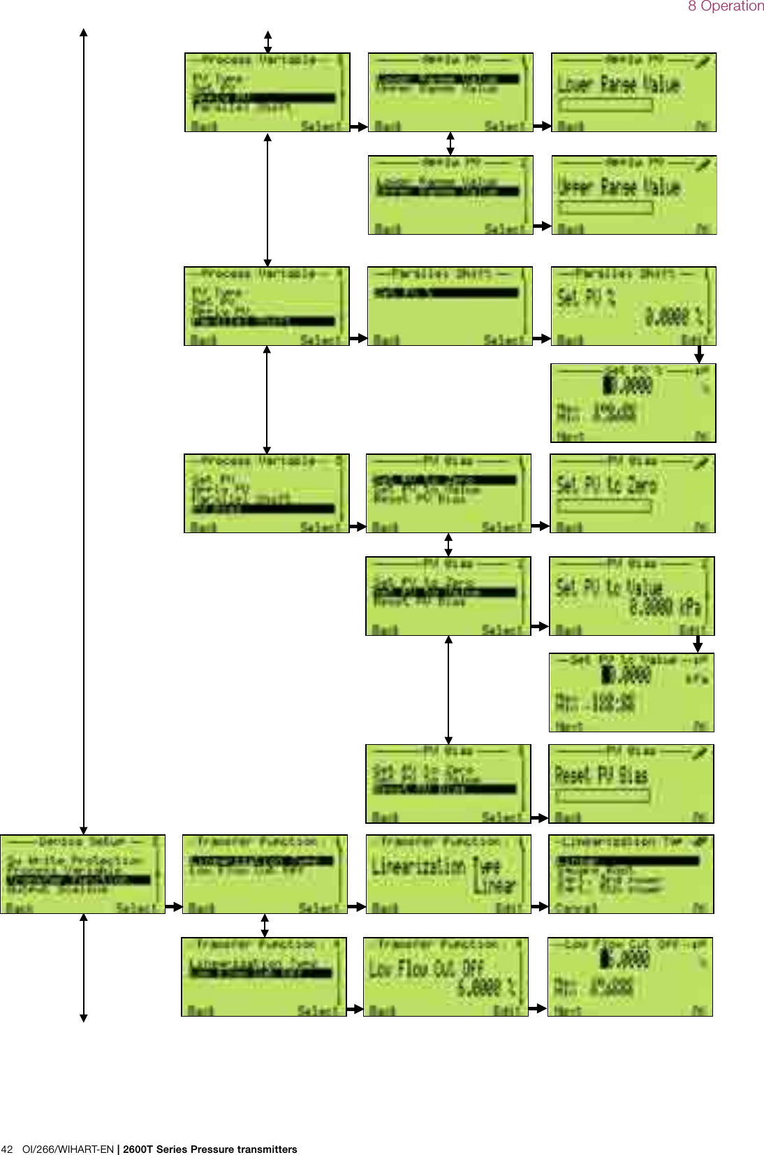
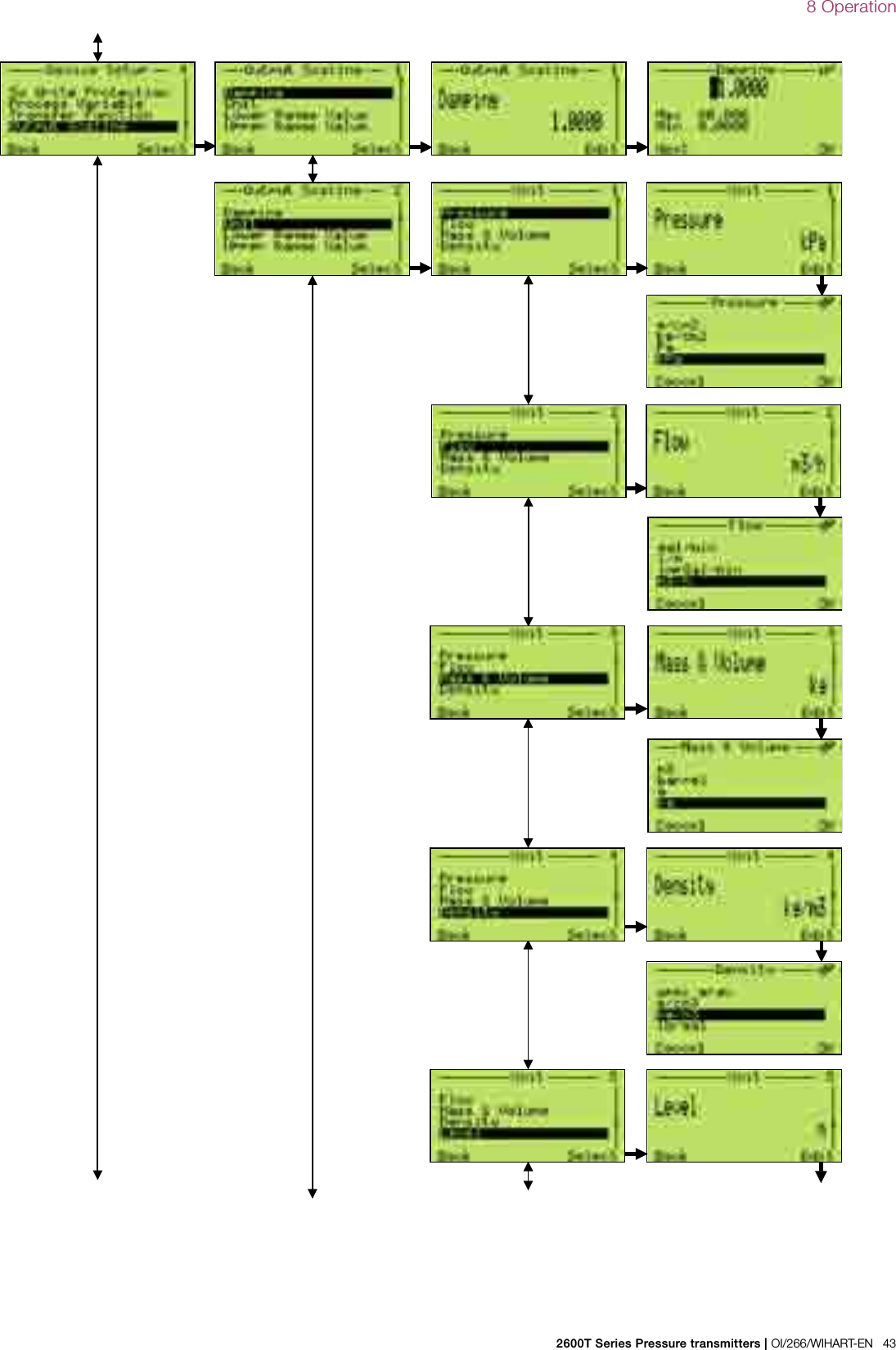
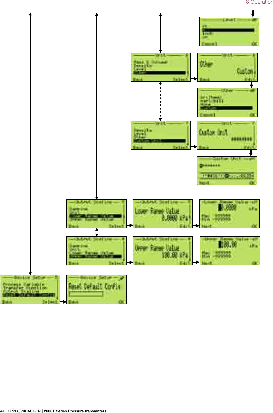
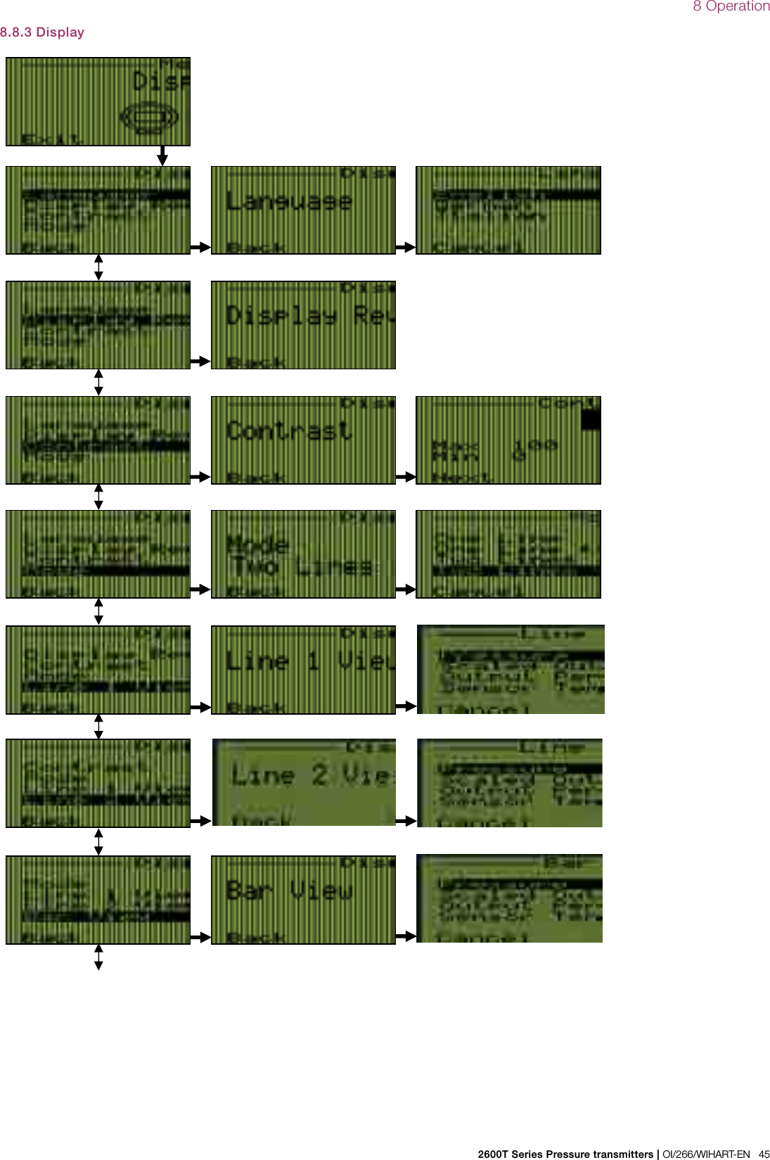
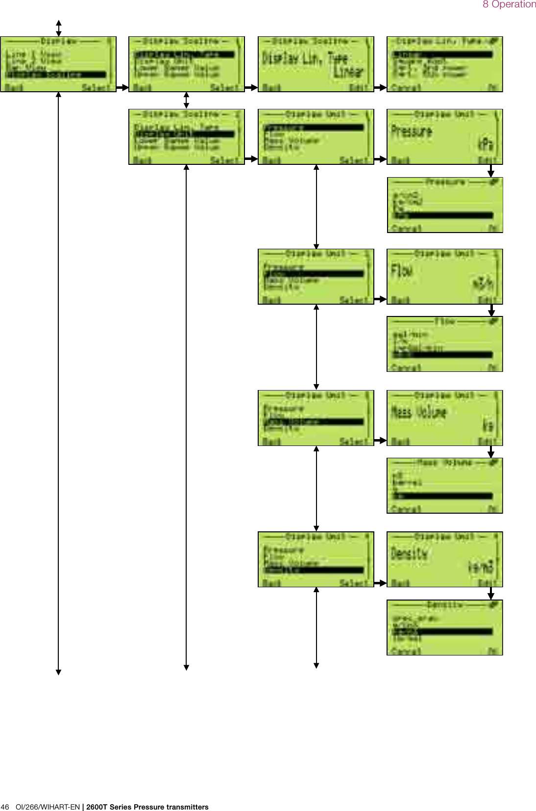
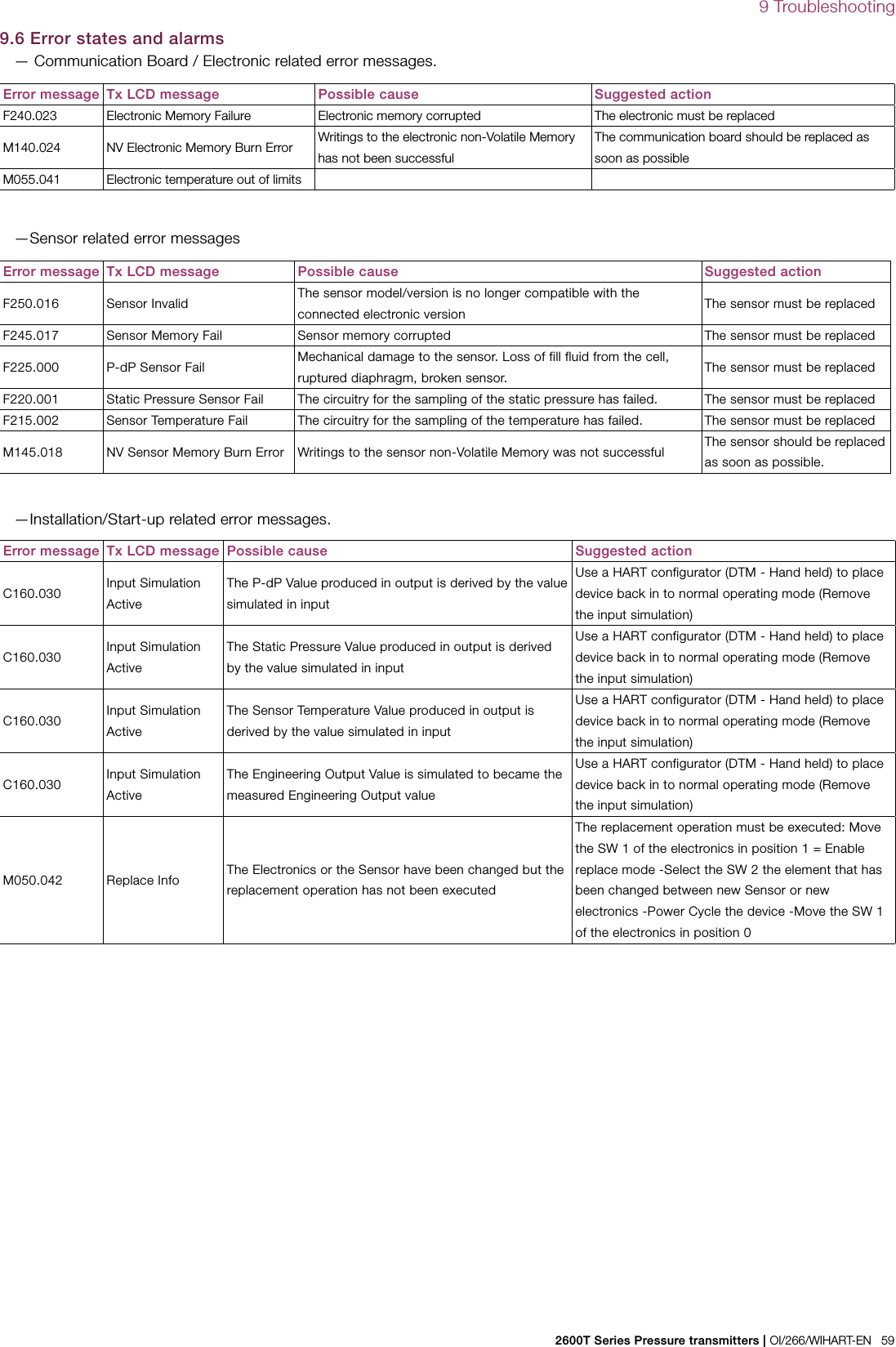
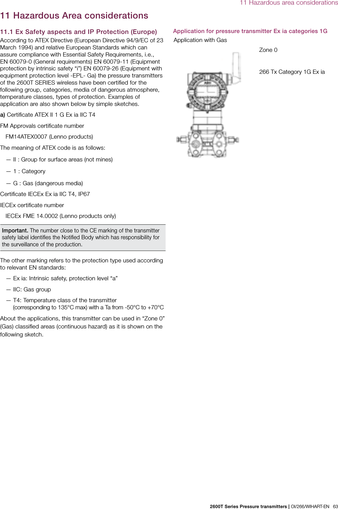
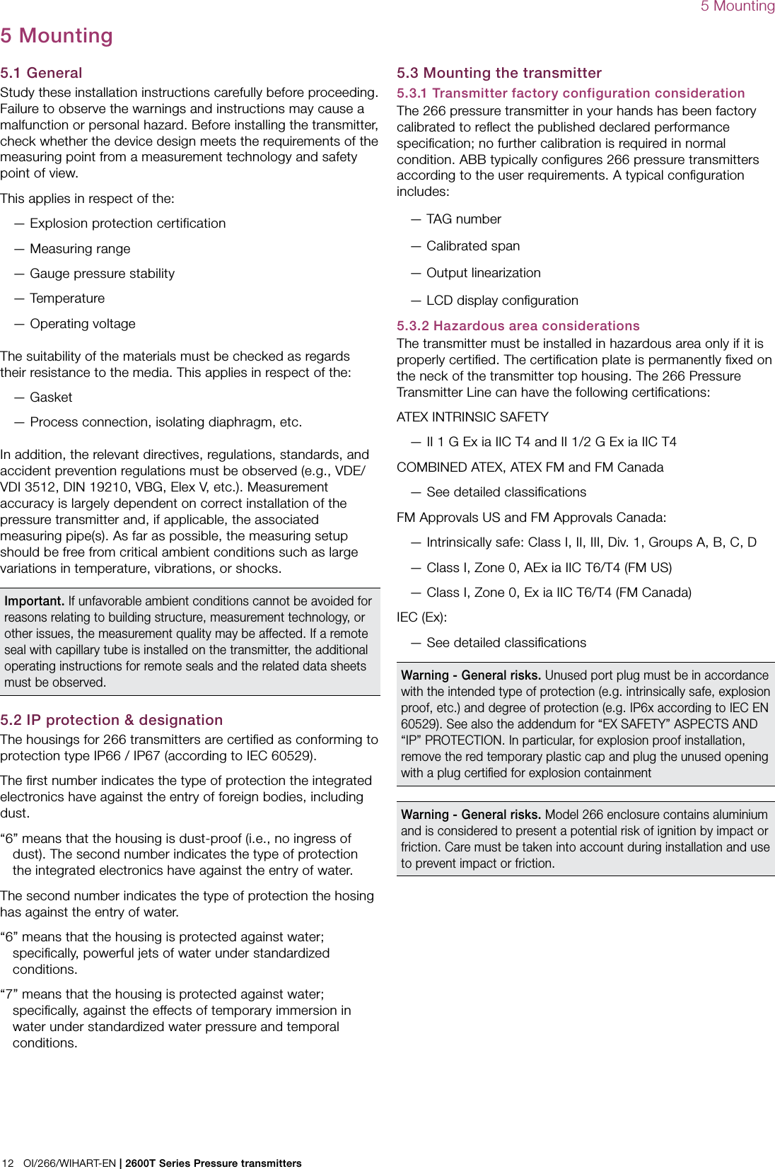
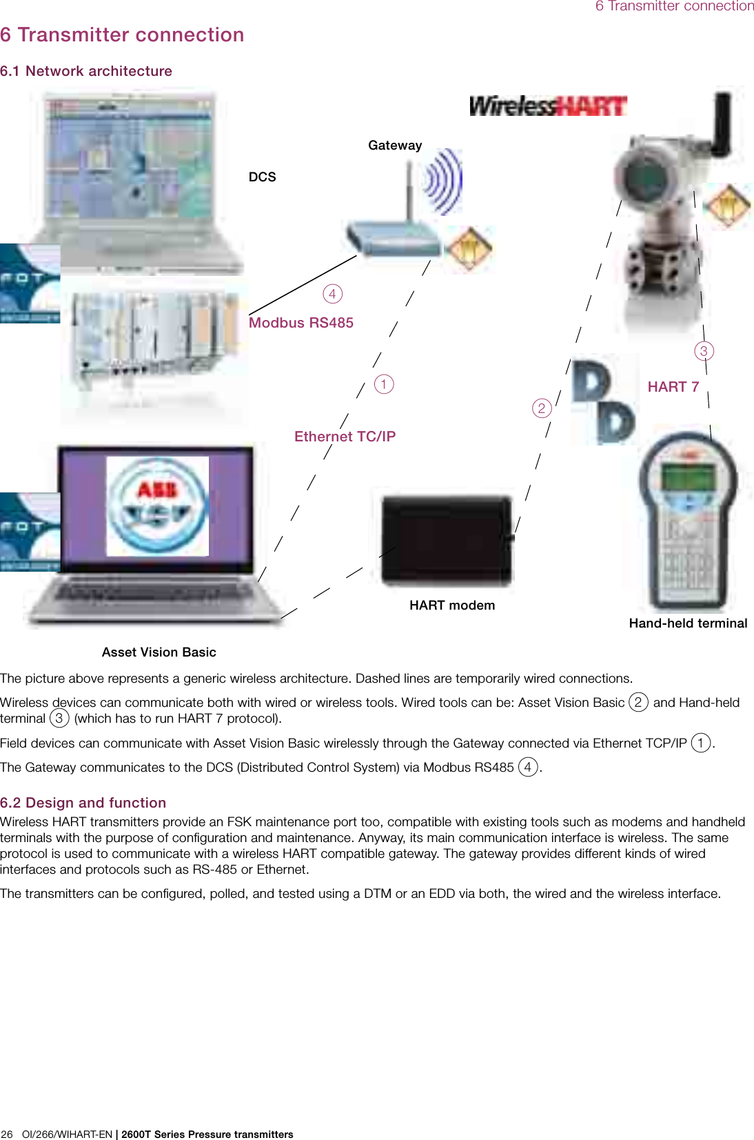
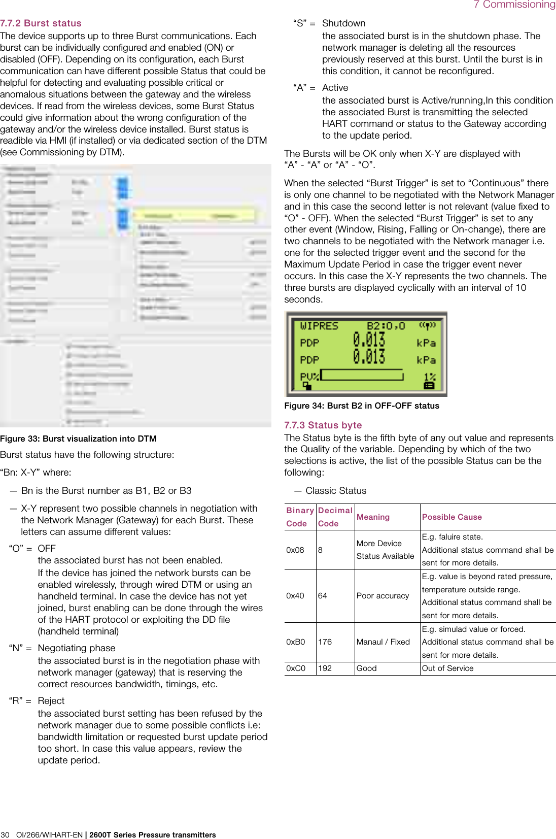
![38 OI/266/WIHART-EN | 2600T Series Pressure transmitters8 Operation8.6 Configuration of the pressure transmitter using the optional integral LCD HMI with keypad (menu-controlled)The integral LCD HMI is connected on the 266 communication board. It can be used to visualize the process measured variables as well as to configure the display and the transmitter.In addition, diagnostic information is provided. To access the functionality of the HMI an activation procedure needs to be carried out. The keypad activation procedure is different between the TTG (Trough The Glass) version and the conventional HMI.Figure 37: Display keypadThe keys (1) , (4) , (2) and (3) are available for the menu-controlled configuration. — The menu / submenu name is displayed above in the LCD display. — The number/line of the currently selected menu item is displayed in the upper right of the LCD display. — A scroll bar is located on the right edge of the LCD display which shows the relative position of the currently selected menu item within the menu. — Both of the keys (1) and (4) can have various functions. The meaning of these buttons is displayed below in the LCD display above the respective button. — You can browse through the menu or select a number within a parameter value using both keys (2) and (3) . The button (4) selects the desired menu item.Button (1) functionalities MeaningExit Exit menuBack Back one submenuCancel Exit without saving the selected parameter valueNext Select next position for entering numerical values or lettersButton (4) functionalities MeaningSelect Select submenu/parameterEdit Edit parameterOk Save selected parameter and display stored parameter value8.7 HMI as feedback of the local push button operationsAs consequence of the operations described in the section 8.2, when the Z or S buttons are released, the feedback of the executed operation is displayed in the bottom of the LCD (same position as per diagnostic messages):Message Description! Oper Done The push button operation has been successfully executed! Proc Too LowThe Pressure measured in input is too low and not acceptable for the requested operation! Proc Too HighThe Pressure measured in input is too high and not acceptable for the requested operation! New URV ErrorThe Zero (Z) operation cannot be accepted because the URV would be shifted outside the Upper Sensor limit! Span ErrorThe Span (S) operation cannot be accepted because the new URV would be too close to the LRV and their difference lower than the Minimum Span value ! Oper Disabled The push button operation has been refused because the Write Protection is enabled.! LRV Too LowNew LRV is too low and not acceptable for the requested operationLRV Too HighNew LRV is high low and not acceptable for the requested operationURV Too LowNew URV is too low and not acceptable for the requested operationURV Too HighNew URV is high low and not acceptable for the requested operationArmed Device is armed to accept HART command 73 “Find Device”. This message can be triggered only during the device wakeup operation8.8 HMI menu structureThe HMI menu is divided in the following sections which can be selected by acting on the keys (2) and (3) , once on the display the desired sub-menu icon will be visualized, confirm your selection with the [SELECT] key (4) .Follow the instruction on the screen to perform the configuration of the different parameters.](https://usermanual.wiki/ABB/WICB/User-Guide-2536030-Page-38.png)