User Manual
2600T Series Pressure Transmitters
266 Models
WirelessHART
Operating Instruction OI/266/WIHART-EN
Engineered solutions for all
applications
2 OI/266/WIHART-EN | 2600T Series Pressure transmitters
The Company
We are an established world force in the design and manufacture of measurement products for industrial process control, flow
measurement, gas and liquid analysis and environmental applications.
As a part of ABB, a world leader in process automation technology, we offer customers application expertise, service and support
worldwide.
We are committed to teamwork, high quality manufacturing, advanced technology and unrivalled service and support.
The quality, accuracy and performance of the Company’s products result from over 100 years experience, combined with
acontinuous program of innovative design and development to incorporate the latest technology.
2600T Series Pressure transmitters | OI/266/WIHART-EN 3
Contents
Index
1. Introduction .........................................................5
1.1 Instruction manual structure ......................................... 5
1.2 Models covered by this manual ..................................... 5
1.3 Product description ...................................................... 5
2 Safety ....................................................................6
2.1 General safety information ............................................ 6
2.2 Improper use ............................................................... 6
2.3 Technical limit values .................................................... 6
2.4 Warranty prevision ........................................................ 6
2.5 Use of instruction ......................................................... 6
2.6 Operator liability ........................................................... 7
2.7 Qualified personnel ....................................................... 7
2.8 Returning devices ......................................................... 7
2.9 Disposal ....................................................................... 7
2.10 Information on WEEE Directive 2002/96/EC ............... 7
2.11 Transport and storage ................................................ 7
2.11.1 Shipping considerations for wireless products ..... 7
2.12 Safety information for battery installation ..................... 7
2.13 Safety information for inspection and maintenance ...... 7
3 Transmitter overview ............................................8
3.1 Transmitter components overview................................. 8
3.2 Range & Span consideration ......................................... 9
4 Opening the box ................................................. 10
4.1 Identification .............................................................. 10
4.2 Optional wired-on SST plate (I1) ................................. 11
4.3 Handling .................................................................... 11
4.4 Storage ...................................................................... 11
5 Mounting ............................................................. 12
5.1 General ...................................................................... 12
5.2 IP protection & designation ......................................... 12
5.3 Mounting the transmitter............................................. 12
5.3.1 Transmitter factory configuration consideration ... 12
5.3.2 Hazardous area considerations ........................... 12
5.4 Pressure Equipment Directive (PED) (97/23/CE) .......... 13
5.4.1 Devices with PS >200 ......................................... 13
5.4.2 Devices with PS ≤200 bar ................................... 13
5.5 Mounting a DP sensor transmitter ............................... 13
5.5.1 Bracket mounting (optional) ................................. 14
5.5.2 B2 Pipe and wall mounting bracket details ........... 16
5.5.3 B5 Flat type bracket details ................................. 17
5.6 Mounting a P style pressure transmitter ...................... 18
5.6.1 B1 and B2 Barrel housing bracket details ............ 19
5.7 Transmitter housing rotation ....................................... 20
5.8 Integral display rotation .............................................. 20
5.9 Antenna rotation ......................................................... 20
5.10 Impulse piping connection for standard instruments .. 20
5.11 Process connections considerations ......................... 21
5.12 Kynar inserts connection .......................................... 21
5.13 Installation recommendations ................................... 22
5.13.1 Steam or clean liquids flow measurement .......... 22
5.13.2 Gas or liquid flow measurement ......................... 22
5.13.3 Liquid level measurements (dry leg) ................... 23
5.13.4 Liquid level measurement (wet leg) .................... 23
5.13.5 Liquid level measurement with open tanks ......... 23
5.13.6 Pressure measurement of a tank ....................... 24
5.13.7 Pressure measurement of a liquid in a pipe ........ 24
5.13.8 Pressure measurement of vapor in a pipe ......... 25
5.13.9 Pressure measurement of a gas in a pipe ........... 25
6 Transmitter connection ....................................... 26
6.1 Network architecture .................................................. 26
6.2 Design and function .................................................. 26
6.3 HART ......................................................................... 27
6.4 Supply requirement .................................................... 27
6.5 Powering the transmitter on ........................................ 27
6.6 Protective Grounding .................................................. 27
7 Commissioning ................................................... 28
7.1 Standard setting for normal operation ......................... 28
7.2 Standard setting for error detection (alarm) ................. 28
7.3 Write Protection ......................................................... 28
7.4 Correcting the lower range value / zero shift ................ 28
7.5 Correct the zero shift .................................................. 28
7.6 Joining the network .................................................... 29
7.7 Burst ......................................................................... 29
7.7.1 Burst configuration .............................................. 29
7.7.2 Burst status ........................................................ 30
7.7.3 Status byte ......................................................... 30
7.8 Commissioning by HART Handheld Terminal ............... 31
7.8.1 EDD structure for 266 WiPressure ....................... 34
7.9 Commissioning by DTM .............................................. 36
7.9.1 Network Diagnostics by DTM .............................. 36
8 Operation ............................................................ 37
8.1 Local push buttons functionality .................................. 37
8.2 Factory settings ........................................................ 37
8.3 Configuration types .................................................... 37
8.4 Configuring without an integral LCD HMI ..................... 37
8.5 LRV and URV configuration ........................................ 37
8.6 Configuration using the LCD with keypad .................... 38
8.7 HMI as feedback of the local push button operations .. 38
8.8 HMI menu structure .................................................... 38
8.8.1 Easy Set-up ........................................................ 40
8.8.2 Device Set-up ..................................................... 41
8.8.3 Display ............................................................... 45
8.8.4 Calibrate ............................................................. 48
8.8.5 Diagnostics ......................................................... 49
8.8.6 Device Info .......................................................... 50
8.8.7 Communication ................................................... 51
8.9 Transfer function ........................................................ 53
8.9.1 Linear ................................................................. 53
8.9.2 Square root ........................................................ 53
8.9.3 Square root to the 5th power .............................. 54
8.9.4 Custom linearization curve ................................... 54
8.9.5 Bidirectional Flow ............................................... 54
8.9.6 Square root to the 3rd power .............................. 54
8.9.7 Cylindric lying tank ............................................. 55
8.9.8 Spherical Tank ................................................... 55
8.10 Configuration with the PC or handheld terminal ........ 55
8.11 Configuration with DTM - System requirements ......... 55
4 OI/266/WIHART-EN | 2600T Series Pressure transmitters
Contents
9 Troubleshooting .................................................. 56
9.1 Overview .................................................................... 56
9.2 Device-related issues ................................................. 56
9.2.1 Device does not power on ................................... 56
9.3 Network-related issues .............................................. 56
9.3.1 General ............................................................... 56
9.3.2 Device does not join the network ......................... 56
9.3.3 Burst troubleshooting .......................................... 57
9.4 HMI as diagnostic indicator ...................................... 58
9.5 HMI as feedback of the local push button operations .. 58
9.6 Error states and alarms .............................................. 59
10 Maintenance ..................................................... 62
10.1 Returns and removal ................................................ 62
10.2 Pressure transmitter sensor ...................................... 62
10.3 Removing/Installing the process flanges .................... 62
10.4 Pressure transducer replacement .............................. 63
10.5 Electronic replacement ............................................. 63
10.6 Battery replacement ................................................. 63
11 Hazardous Area considerations ........................ 64
11.1 Ex Safety aspects and IP Protection (Europe) ............ 64
11.2 Ex Safety aspects and IP Protection (North America) . 67
11.2.1 Applicable standards ......................................... 67
11.2.2 Classifications ................................................... 67
12 Compliance for Radio and Telecommunication ... 68
12.1 FCC Compliance ...................................................... 68
12.2 IC Compliance ......................................................... 68
12.3 R&TTE Compliance 1999/5/EC ................................. 68
2600T Series Pressure transmitters | OI/266/WIHART-EN 5
1 Introduction
1. Introduction
1.1 Instruction manual structure
The present manual provides information on installing, operating,
troubleshooting the 266 pressure transmitter. Every section of
the present manual is specifically dedicated to the specific phase
of the transmitter lifecycle starting from the receipt of the
transmitter and its identification, passing to the installation, to the
electrical connections, to the configuration and to the
troubleshooting and maintenance operations.
1.2 Models covered by this manual
The present manual can be used for all the 266 wireless
models (266DxH, 266HxH and 266NxH).
1.3 Product description
The pressure transmitters model 266 is a modular range of field
mounted, microprocessor based electronic transmitters,
multiple sensor technologies. Accurate and reliable
measurement of differential pressure, gauge and absolute
pressure, flow and liquid level is provided, in the even most
difficult and hazardous industrial environments. Model 266 can
be configured to provide specific industrial output signals.

6 OI/266/WIHART-EN | 2600T Series Pressure transmitters
2 Safety notes
2 Safety
2.1 General safety information
The “Safety” section provides an overview of the safety aspects
to be observed for operation of the device.
The device has been designed and manufactured in
accordance with the state of the art and is operationally safe. It
has been tested and left the factory in perfect working
conditions. The information in the manual, as well as the
applicable documentation and certificates, must be observed
and followed in order to maintain this condition throughout the
period of operation. Full compliance with the general safety
requirements must be observed during operation of the device.
In addition to the general information, the individual sections in
the manual contain descriptions of processes or procedural
instructions with specific safety information.
Only by observing all of the safety information can you reduce
to the minimum the risk of hazards for personnel and/or
environment. These instructions are intended as an overview
and do not contain detailed information on all available models
or every conceivable event that may occur during setup,
operation, and maintenance work. For additional information,
or in the event of specific problems not covered in detail by
these operating instructions, please contact the manufacturer.
In addition, ABB declares that the contents of this manual are
not part of any prior or existing agreements, commitments, or
legal relationships; nor are they intended to amend these. All
obligations of ABB arise from the conditions of the relevant
sales agreement, which also contains the solely binding
warranty regulations in full. These contractual warranty
provisions are neither extended nor limited by the information
provided in this manual.
Caution. Only qualified and authorized specialist personnel should
be charged with installation, electrical connection, commissioning,
and maintenance of the transmitter. Qualified personnel are persons
who have experience in installation, electrical wiring connection,
commissioning, and operation of the transmitter or similar devices,
and hold the necessary qualifications such as:
— Training or instruction, i.e., authorization to operate and
maintain devices or systems according to safety engineering
standards for electrical circuits, high pressures, and
aggressive media
— Training or instruction in accordance with safety engineering
standards regarding maintenance and use of adequate safety
systems.
For safety reasons, ABB draws your attention to the fact that only
sufficiently insulated tools conforming to IEC 60900 and EN 60900
may be used.
Since the transmitter may form part of a safety chain, we
recommend replacing the device immediately if any defects are
detected. In case of use in Hazardous Area non sparking tools only
must be employed.
In addition, you must observe the relevant safety regulations
regarding the installation and operation of electrical systems,
and the relevant standards, regulations and guidelines about
explosion protection.
Warning. The device can be operated at high levels of pressure
and with aggressive media. As a result, serious injury or significant
property damage may occur if this device is operated incorrectly.
2.2 Improper use
It is prohibited to use the device for the following purposes:
— As a climbing aid, e.g., for mounting purposes
— As a support for external loads, e.g., as a support for pipes.
— Adding material, e.g., by painting over the name plate or
welding/soldering on parts
— Removing material, e.g., by drilling the housing.
Repairs, alterations, and enhancements, or the installation of
replacement parts, are only permissible as far as these are
described in the manual. Approval by ABB must be requested
for any activities beyond this scope. Repairs performed by
ABB-authorized centers are excluded from this.
2.3 Technical limit values
The device is designed for use exclusively within the values
stated on the name plates and within the technical limit values
specified on the data sheets.
The following technical limit values must be observed:
— The Maximum Working Pressure may not be exceeded.
— The Maximum ambient operating temperature may not be
exceeded.
— The Maximum process temperature may not be
exceeded.
— The housing protection type must be observed.
2.4 Warranty prevision
Using the device in a manner that does not fall within the scope
of its intended use, disregarding this manual, using
underqualified personnel, or making unauthorized alterations,
releases the manufacturer from any liability for any resulting
damage. This makes the manufacturer’s warranty null and void.
2.5 Use of instruction
Danger – <Serious damage to health/risk to life>. This message
indicates that an imminent risk is present. Failure to avoid this will
result in death or serious injury.
Caution – <Minor injuries>. This message indicates a potentially
dangerous situation. Failure to avoid this could result in minor
injuries. This may also be used for property damage warnings.
Important. This message indicates indicates operator tips or
particularly useful information. It does not indicate a dangerous or
damaging situation.
Warning – <Bodily injury>. This message indicates a potentially
dangerous situation. Failure to avoid this could result in death or
serious injury
Attention – <Property damage>. This message indicates a
potentially damaging situation. Failure to avoid this could result in
damage to the product or its surrounding area.

2600T Series Pressure transmitters | OI/266/WIHART-EN 7
2 Safety notes
2.6 Operator liability
Prior to using corrosive and abrasive materials for measurement
purposes, the operator must check the level of resistance of all
parts coming into contact with the materials to be measured.
ABB will gladly support you in selecting the materials, but cannot
accept any liability in doing so.The operators must strictly
observe the applicable regulations with regard to installation,
function tests, repairs, and maintenance of electrical devices.
2.7 Qualified personnel
Installation, commissioning, and maintenance of the device may
only be performed by trained specialist personnel who have
been authorized by the plant operator. The specialist personnel
must have read and understood the manual and comply with its
instructions.
2.8 Returning devices
Use the original packaging or suitably secure shipping package if
you need to return the device for repair or recalibration
purposes. Fill out the return form (see the end of the document)
and include this with the device. According to EC guidelines and
other local laws for hazardous materials, the owner of hazardous
waste is responsible for its disposal. The owner must observe
the proper regulations for shipping purposes. All devices sent
back to ABB must be free from any hazardous materials (acids,
alkalis, solvents, etc.).
2.9 Disposal
ABB actively promotes environmental awareness and has an
operational management system that meets the requirements of
DIN EN ISO 9001:2008, EN ISO 14001:2004, and OHSAS
18001. Our products and solutions are intended to have
minimum impact on the environment and persons during
manufacturing, storage, transport, use and disposal. This
includes the environmentally friendly use of natural resources.
ABB conducts an open dialog with the public through its
publications. This product is manufactured from materials that
can be reused by specialist recycling companies.
2.10 Information on WEEE Directive 2002/96/EC
(Waste Electrical and Electronic Equipment)
This product or solution is not subject to the WEEE Directive
2002/96/EC or corresponding national laws (e.g., the ElektroG -
Electrical and Electronic Equipment Act - in Germany). Dispose
of the product/solution directly at a specialist recycling facility; do
not use municipal garbage collection points for this purpose.
According to the WEEE Directive 2002/96/EC, only products
used in private applications may be disposed of at municipal
garbage facilities. The included battery shall be disposed
according to European Battery Directive 2006/66/EC which is
transposed individually in each EU member state. Proper
disposal prevents negative effects on people and the
environment, and supports the reuse of valuable raw materials.
ABB can accept and dispose of returns for a fee.
2.11 Transport and storage
— After unpacking the device, check for transport damage.
— Check the packaging material for accessories.
— During intermediate storage or transport, store the
pressure transmitter in the original packaging only.
For information on permissible ambient conditions for storage
and transport, see “Technical data”. Although there is no limit on
the duration of storage, the warranty conditions stipulated on the
order acknowledgment from the supplier still apply.
2.11.1 Shipping considerations for wireless products
containing Lithium batteries
The device is shipped with a Lithium battery in shape of a D-Cell.
The battery is already installed.
Transport of lithium batteries is subject to specific regulations.
Regulations are based on the United Nations Model Regulations
on the Transport of Dangerous Goods. The most important
regulations can be summarized as follows:
C- and D-size cells as well as larger cells and most battery
packs have to be transported under dangerous goods
regulations.
Lithium batteries below 2 grams lithium content (corresponding
approximately to 3 AA cells) are exempted from dangerous
goods regulations but each package requires a special label to
indicate that it contains lithium batteries and special procedures
shall be followed when a package is damaged during
transportation.
Transport regulations require that lithium cells and batteries of all
kinds, exempted or not, be tested according to the UN test
methods.
Packing instructions for air transport of lithium batteries
worldwide are revised bienially by the International Civil Aviation
Organization (ICAO) and distributed in various languages by the
International Air Transport Association (IATA). According to the
regulations, Tadiran Lithium Batteries are classified as lithium
metal batteries. Different regulations are valid for transport in the
USA.
2.12 Safety information for battery installation
The battery shall be installed by specialist personnel paying
attention to the polarity.
2.13 Safety information for inspection and
maintenance
Warning – Risk to persons. There is no EMC protection or
protection against accidental contact when the housing cover is
open. There are electric circuits within the housing which are
dangerous if touched. Therefore, the auxiliary power must be
switched off before opening the housing cover.
Warning – Risk to persons The device can be operated at high
pressure and with aggressive media. Any process media released
may cause severe injuries. Depressurize the pipeline/tank before
opening the transmitter connection.
Corrective maintenance work may only be performed by trained
personnel.
— Before removing the device, depressurize it and any
adjacent lines or containers.
— Check whether hazardous materials have been used as
materials to be measured before opening the device.
Residual amounts of hazardous substances may still be
present in the device and could escape when the device is
opened.
— Within the scope of operator responsibility, check the
following as part of a regular inspection:
Pressure-bearing walls/lining of the pressure device
Measurement-related function
Leak-tightness
Wear (corrosion)
8 OI/266/WIHART-EN | 2600T Series Pressure transmitters
3 Transmitter overview
3 Transmitter overview
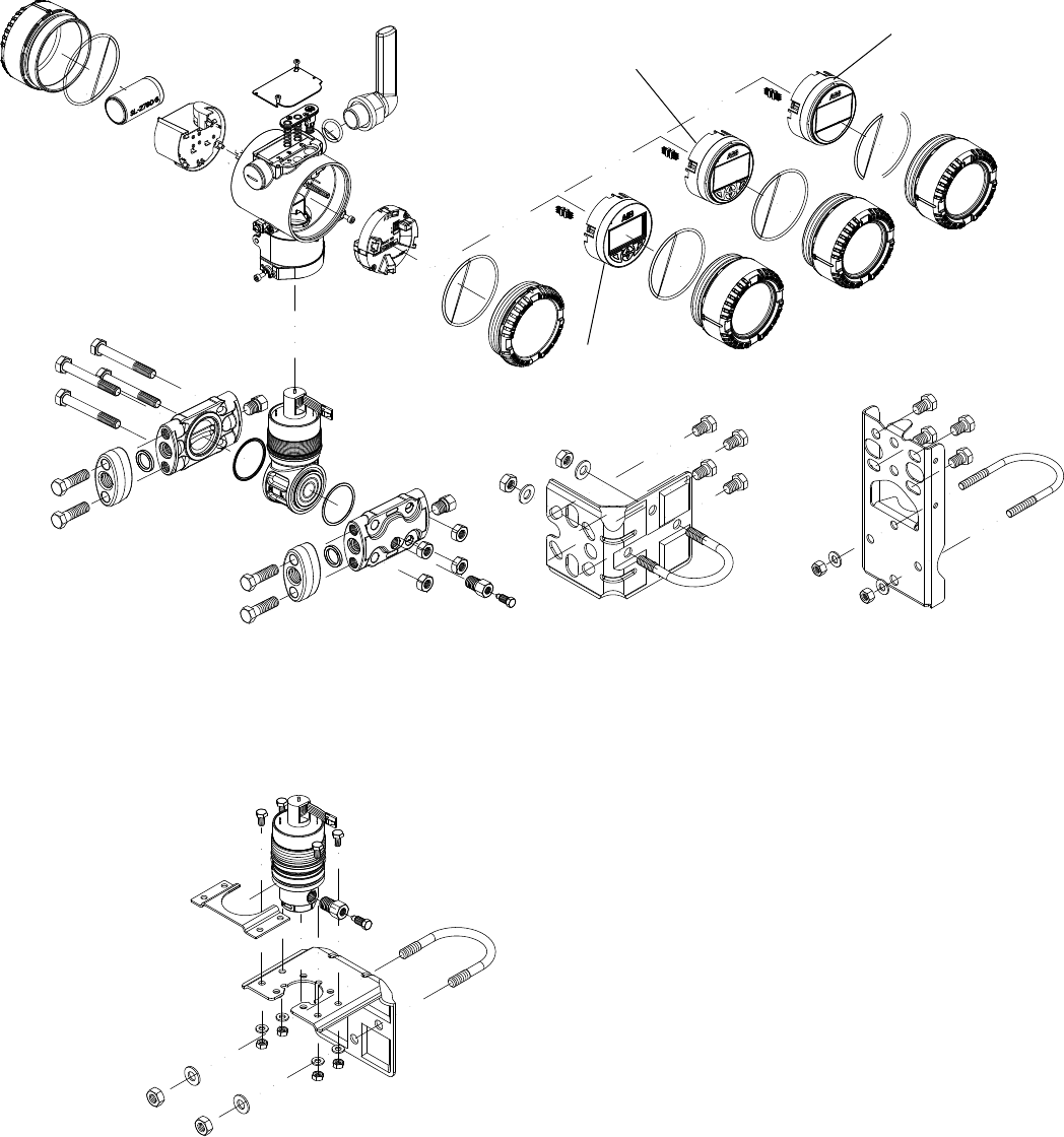
3.1 Transmitter components overview
Figure 1: Pressure transmitter components
1
1 - LCD display with keypad (L1 option)
2 - TTG display with keypad (L5 option)
3 - Standard LCD display (L9 option)
2
3
2600T Series Pressure transmitters | OI/266/WIHART-EN 9
3 Transmitter overview
3.2 Range & Span consideration
The 2600T Transmitter Specification Sheets provide all
information concerning the Range and Span limits in relation to
the model and the sensor code.
The terminology currently used to define the various
parameters is as follows:
URL: Upper Range Limit of a specific sensor. The highest
value of the measured value that the transmitter can
be adjusted to measure.
LRL: Lower Range Limit of a specific sensor. The lowest
value of the measured value that the transmitter can
be adjusted to measure.
URV: Upper Range Value. The highest value of the
measured value to which the transmitter is calibrated.
LRV: Lower Range Value. The lowest value of the
measured value to which the transmitter is calibrated.
SPAN: The algebraic difference between the Upper and
Lower Range Values. The minimum span is the
minimum value that can be used without degradation
of the specified performance.
TD: (or Turn Down Ratio)is the ratio between the
maximum span and the calibrated span.
The transmitter can be calibrated with any range between the
LRL and the URL with the following limitations:
LRL ≤ LRV ≤ (URL - CAL SPAN)
CAL SPAN ≥ MIN SPAN
URV ≤ URL
10 OI/266/WIHART-EN | 2600T Series Pressure transmitters
4 Opening the box
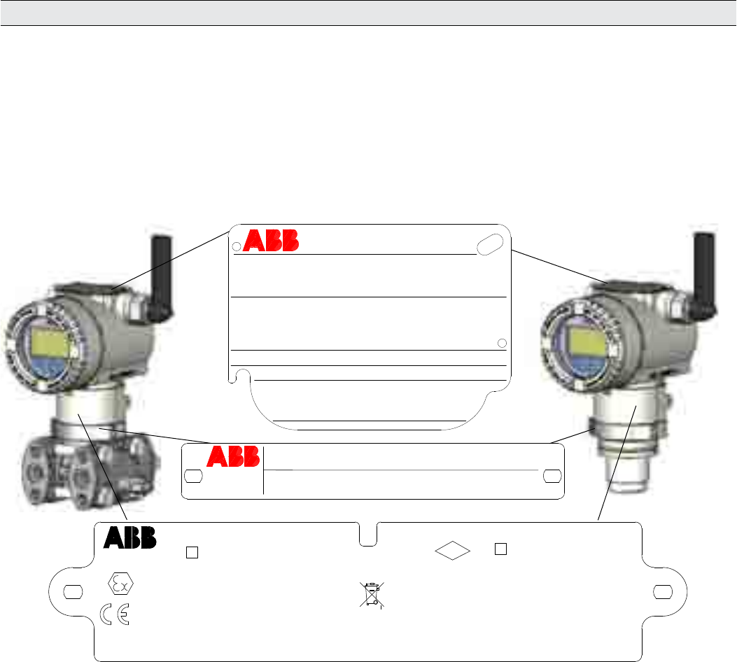
Figure 2: Product identification
Local keys below label
PRODUCT CODE
SEAL-H SEAL-L
SPEC.REQUEST
LRL/URL
SPAN LIMITS
POWER SUPPLY OUTPUT SIGNAL
ABB S.p.A.
Made in Italy
TS PS
SERIAL\NUMBER
SENSOR DIAPH.-FILL
FLANGE/CONN.-GASKET/S
H DIAPH.-FILL
L DIAPH.-FILL
SEAL
HW Rev. MD:
PED:
MWP/OVP
0474
0722
II 1 G Ex ia IIC T4 - II 1/2 G Ex ia IIC T4
FM14ATEX0007X - IECEx FME 14.0002X
Lithium inorganic battery inside
IS/Sec. Intrinseque (Entity) CL I,
ZONE 0 AEx/Ex ia IIC T4
CL I/DIV1/GP ABCD
APPROVED
FM
C US
-50°C < Ta < +70°C - IP67
WARNING : USE ONLY ABB BATTERY CODE 3KXP004006U0100
Contains FCC ID : 2AC5O-WICB
This device complies with part 15 of the FCC Rules. Operation is subject to the following two conditions :
(1) This device may not cause harmful interference, and (2) this device must accept any interference received,
including interference that may cause undesidered operation.
Contains IC : 12311A-WICB
ABB S.p.A.
Lenno (Co) Italy
A
B
C
4 Opening the box
4.1 Identification
The instrument is identified by the data plates shown in Figure 3. The certification plate (ref. A): contains the certification related
parameters for use in Hazardous area.
The Nameplate (ref.B) provides information concerning the model code, maximum working pressure, range and span limits, power
supply , output signal, diaphragms material, fill fluid, range limit, serial number, maximum process working pressure (PS) and
temperature (TS).
Important.
Please refer to the serial number when making enquiries to ABB Service department.
The Tag plate (ref.C) also provides customer tag number and calibrated range. The instrument may be used as a pressure
accessory (category III) as defined by the Pressure Equipment Directive 97/23/EC. In this case, near the CE mark, you will find the
number of the notified body (0474) that have verified the compliance. 266 pressure transmitters are in compliance with
EMC 2004/108/CE.
The certification plate (ref.A) shown here is issued by ABB S.p.A, 22016 Lenno, Italy, with the numbers:
— FM14ATEX0007 or IECEx FME 14.0002 (Ex ia)
— FM14ATEX0008 or IECEx FME 14.0002 (Ex nA)
CE-Identification number of the notified bodies to Pressure Equipment Directive: 0474, to ATEX certification: 0722, to IECEx
certification: IT/CES/QAR07.0001/02.
2600T
Tag
Number
Calib.
Range
PRESSURE TRANSMITTER

2600T Series Pressure transmitters | OI/266/WIHART-EN 11
4 Opening the box
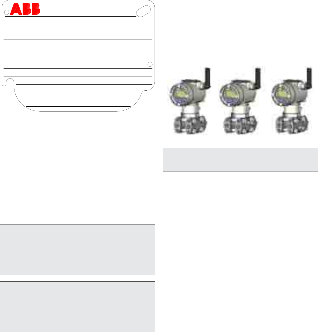
4.2 Optional wired-on SST plate (I1)
The 266 transmitter can be supplied with the optional “Wired
On Stainless Steel plate” (figure 4) which is permanently laser
printed with a custom text specified in phase of order. The
available space consists in 4 lines with 32 characters per line.
The plate will be connected to the transmitter with a Stainless
Steel wire.
AAAAAAAAAAAAAAAAAAAAAAAAAAAAAAAA
BBBBBBBBBBBBBBBBBBBBBBBBBBBBBBBB
CCCCCCCCCCCCCCCCCCCCCCCCCCCCCCCC
DDDDDDDDDDDDDDDDDDDDDDDDDDDDDDDD
Figure 3: 4-line layout of the optional wired-on Stainless Steel plate
4.3 Handling
The instrument does not require any special precautions during
handling although normal good practice should be observed.
4.4 Storage
The instrument does not require any special treatment if stored
as dispatched and within the specified ambient conditions.
There is no limit to the storage period, although the terms of
guarantee remain as agreed with the Company and as given in
the order acknowledgement.
Lithium batteries installed into the WirelessHART pressure
transmitter should be stored in a clean and dry area. For
maximum battery life, storage temperature should not exceed
30° C (86 °F).

12 OI/266/WIHART-EN | 2600T Series Pressure transmitters
5 Mounting
5 Mounting
5.1 General
Study these installation instructions carefully before proceeding.
Failure to observe the warnings and instructions may cause a
malfunction or personal hazard. Before installing the transmitter,
check whether the device design meets the requirements of the
measuring point from a measurement technology and safety
point of view.
This applies in respect of the:
— Explosion protection certification
— Measuring range
— Gauge pressure stability
— Temperature
— Operating voltage
The suitability of the materials must be checked as regards
their resistance to the media. This applies in respect of the:
— Gasket
— Process connection, isolating diaphragm, etc.
In addition, the relevant directives, regulations, standards, and
accident prevention regulations must be observed (e.g., VDE/
VDI 3512, DIN 19210, VBG, Elex V, etc.). Measurement
accuracy is largely dependent on correct installation of the
pressure transmitter and, if applicable, the associated
measuring pipe(s). As far as possible, the measuring setup
should be free from critical ambient conditions such as large
variations in temperature, vibrations, or shocks.
Important. If unfavorable ambient conditions cannot be avoided for
reasons relating to building structure, measurement technology, or
other issues, the measurement quality may be affected. If a remote
seal with capillary tube is installed on the transmitter, the additional
operating instructions for remote seals and the related data sheets
must be observed.
5.2 IP protection & designation
The housings for 266 transmitters are certified as conforming to
protection type IP66 / IP67 (according to IEC 60529).
The first number indicates the type of protection the integrated
electronics have against the entry of foreign bodies, including
dust.
“6” means that the housing is dust-proof (i.e., no ingress of
dust). The second number indicates the type of protection
the integrated electronics have against the entry of water.
The second number indicates the type of protection the hosing
has against the entry of water.
“6” means that the housing is protected against water;
specifically, powerful jets of water under standardized
conditions.
“7” means that the housing is protected against water;
specifically, against the effects of temporary immersion in
water under standardized water pressure and temporal
conditions.
5.3 Mounting the transmitter
5.3.1 Transmitter factory configuration consideration
The 266 pressure transmitter in your hands has been factory
calibrated to reflect the published declared performance
specification; no further calibration is required in normal
condition. ABB typically configures 266 pressure transmitters
according to the user requirements. A typical configuration
includes:
— TAG number
— Calibrated span
— Output linearization
— LCD display configuration
5.3.2 Hazardous area considerations
The transmitter must be installed in hazardous area only if it is
properly certified. The certification plate is permanently fixed on
the neck of the transmitter top housing. The 266 Pressure
Transmitter Line can have the following certifications:
ATEX INTRINSIC SAFETY
— II 1 G Ex ia IIC T4 and II 1/2 G Ex ia IIC T4
COMBINED ATEX, ATEX FM and FM Canada
— See detailed classifications
FM Approvals US and FM Approvals Canada:
— Intrinsically safe: Class I, II, III, Div. 1, Groups A, B, C, D
— Class I, Zone 0, AEx ia IIC T6/T4 (FM US)
— Class I, Zone 0, Ex ia IIC T6/T4 (FM Canada)
IEC (Ex):
— See detailed classifications
Warning - General risks. Unused port plug must be in accordance
with the intended type of protection (e.g. intrinsically safe, explosion
proof, etc.) and degree of protection (e.g. IP6x according to IEC EN
60529). See also the addendum for “EX SAFETY” ASPECTS AND
“IP” PROTECTION. In particular, for explosion proof installation,
remove the red temporary plastic cap and plug the unused opening
with a plug certified for explosion containment
Warning - General risks. Model 266 enclosure contains aluminium
and is considered to present a potential risk of ignition by impact or
friction. Care must be taken into account during installation and use
to prevent impact or friction.
2600T Series Pressure transmitters | OI/266/WIHART-EN 13
5 Mounting
Figure 4: 266 nameplate with PED data
Local keys below label
PRODUCT CODE
SEAL-H SEAL-L
SPEC.REQUEST
LRL/URL
SPAN LIMITS
POWER SUPPLY OUTPUT SIGNAL
ABB S.p.A.
Made in Italy
TS PS
SERIAL\NUMBER
SENSOR DIAPH.-FILL
FLANGE/CONN.-GASKET/S
H DIAPH.-FILL
L DIAPH.-FILL
SEAL
HW Rev. MD:
PED:
MWP/OVP
Important. In case of a High Static differential pressure transmitter,
please notice that the Vent/Drain valves can be configured only on
the process axis (V1).
5.4.2 Devices with PS ≤200 bar
Devices with a permissible pressure PS ≤200 bar correspond
to article 3 paragraph (3). They have not been subject to a
conformity validation. These instruments were designed and
manufactured acc. to SEP Sound Engineering Practices.
5.5 Mounting a DP sensor transmitter
(266DS/266DR)
The pressure transmitter model 266DS can be mounted directly
on the manifold. A mounting bracket for wall or pipe mounting
(2” pipe) is also available as an accessory. For model 266DR
always mounting brackets should be used. Ideally, the pressure
transmitter should be mounted in a vertical position to prevent
subsequent zero shifts.
Important. If the transmitter is installed inclined with respect to the
vertical, the filling liquid exerts hydrostatic pressure on the
measuring diaphragm, resulting in a zero shift. In such an event, the
zero point can be corrected via the zero push-button or via the “set
PV to zero” command. Please refer to the [configuration section] for
further details. For transmitters without diaphragm seals, please
read the following considerations on the Vent/Drain.
Attention − Potential damage to transmitter. In case of a High
Static differential pressure transmitter (266DSH.x.H) please always
open the equalization valve of the manifold (if installed) before
applying pressure to the transmitter. High Static pressure can
damage the sensor causing a zero shift and a serious decrease of
the total performance in terms of accuracy. In this case, please
perform a full sensor trim.
It is important to mount the transmitter and to lay the process
Figure 5: Drain/vent valves configuration (respectively V1, V2, V3)
5.4 Pressure Equipment Directive (PED) (97/23/CE)
5.4.1 Devices with PS >200
Devices with a permissible pressure PS >200 bar have been
subject to a conformity validation. The data label includes the
following specifications:
piping so that gas bubbles, when measuring liquids, or
condensate when measuring gases, will flow back to the
process and not enter the transmitter measuring chamber.
Optional Vent/drain valves (code V1/V2/V3) on the transmitter
are located on the sensor flanges.
The transmitter has to be positioned so that these drain/vent
valves will be located higher than the taps on liquid service in
order to allow the venting of entrapped gas or below the taps
on gas service in order to allow the air to vent off or
condensate to drain off. For safety reasons, take care of the
drain/vent valves position so that when the process fluid is
removed during the drain/vent operation it is directed down
and away from technicians. It is recommended to mount the
transmitter to prevent this possible source of damage for
unskilled operators.
14 OI/266/WIHART-EN | 2600T Series Pressure transmitters
5 Mounting
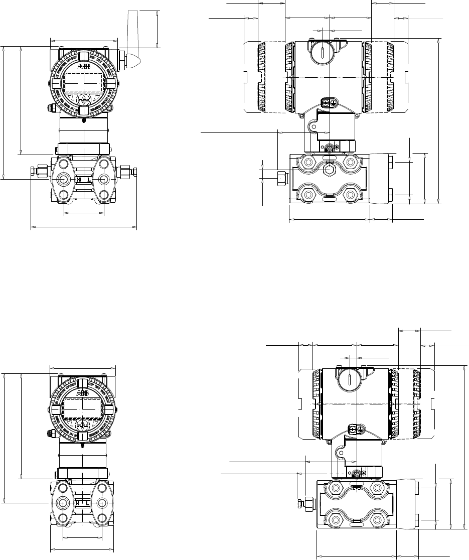
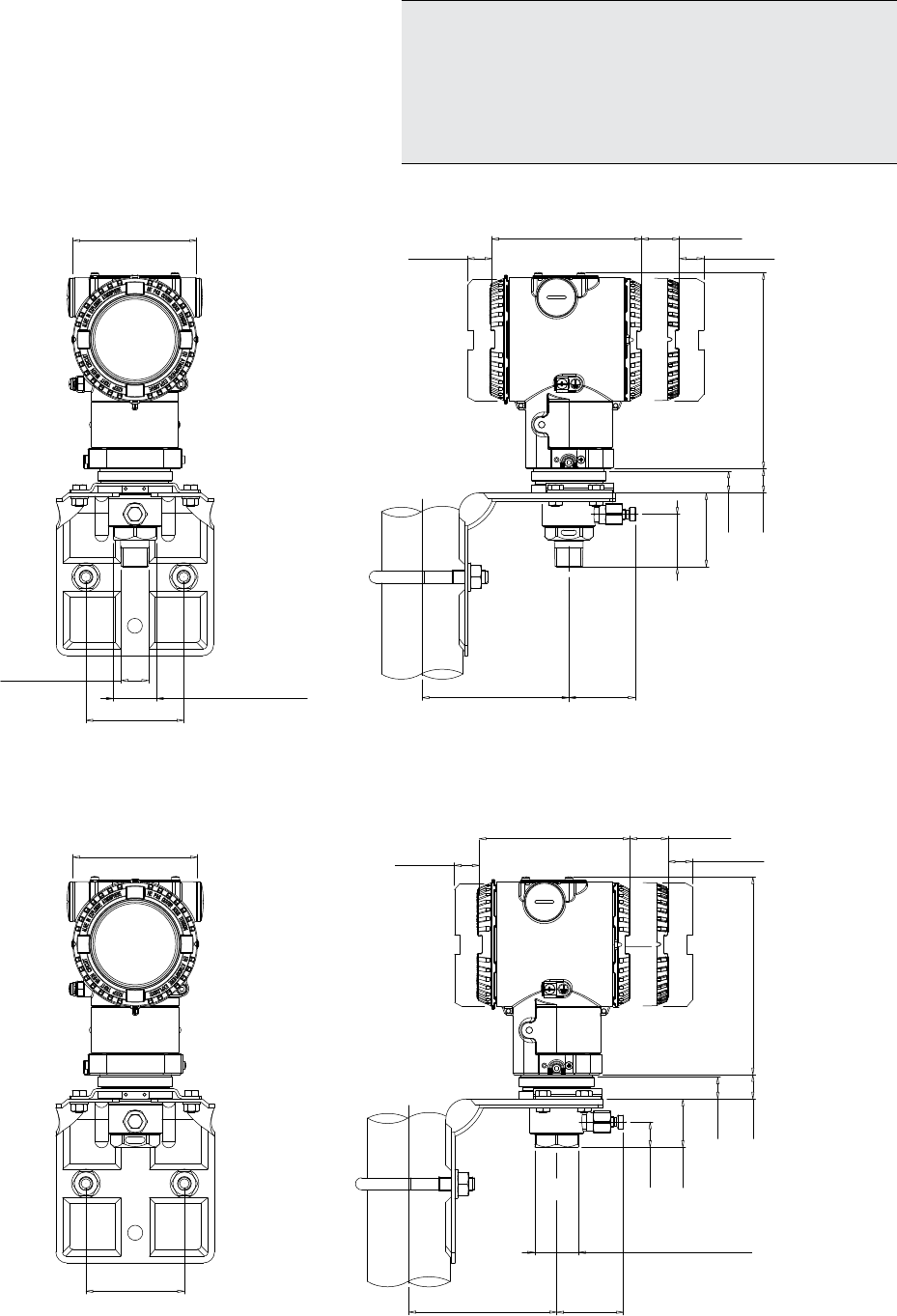
5.5.1 Bracket mounting (optional)
Different mounting brackets are available please refer to the relevant installation drawing below:
142 (5.59)
179 (7.02)
91 (3.58)
145 (5.70)
(*)
70 (2.75)
Figure 6: Differential Pressure Style transmitter with barrel housing installed on a horizontal pipe with optional bracket (B2)
96.8 (3.81)
100 (3.94) for NACE bolting
179 (7.02)
91 (3.58)
145 (5.70)
54 (2.13)
78 (3.07) with d/v valve
29 (1.14)
18 (0.71)
18 (0.71)
210 (8.28)
58 (2.28) 55 (2.17)
66 (2.60) with plug
41.3 (1.63)
65 (2.53)
102 (4.02) 29 (1.12)
9 (0.35)
Figure 7: Differential Pressure Style transmitter (High Static option)
78 (3.07) with d/v valve
29 (1.14)
18 (0.71)
210 (8.28)
58 (2.28) 55 (2.17)
11 (0.43)
66 (2.60) with plug
41.3 (1.63)
65 (2.53)
102 (4.02) 29 (1.12)
9 (0.35)
29 (1.14)
18 (0.71)
2600T Series Pressure transmitters | OI/266/WIHART-EN 15
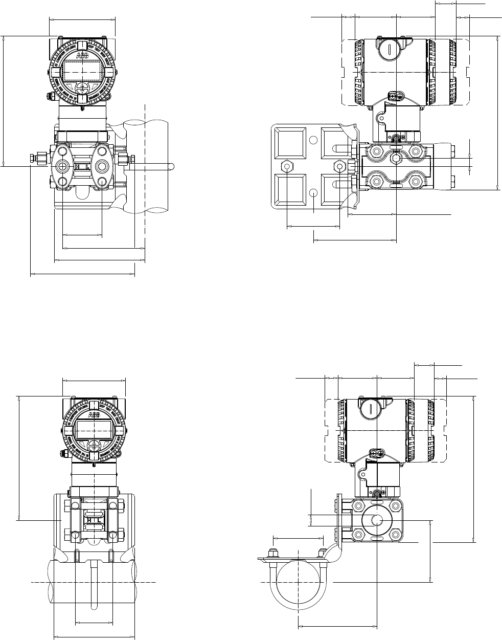
5 Mounting
142 (5.59)
(*)
179 (7.02)
91 (3.58)
123 (4.86)
113 (4.43)
29 (1.14)
18 (0.71)
18 (0.71)
210 (8.28)
113 (4.45)
11 (0.43)
72 (2.83)
66 (2.60) with plug
78 (3.07) with d/v valve
58 (2.28) 55 (2.17)
Figure 8: Differential Pressure Style transmitter with barrel housing installed on a vertical pipe with optional bracket (B2)
91 (3.58)
179 (7.02)
54 (2.13)
116 (4.57)
29 (1.14)
18 (0.71)
113 (4.45)
72 (2.83)
210 (8.28)
18 (0.71) 58 (2.28) 55 (2.17)
89 (3.48)
1/4 or
1/2 NPT
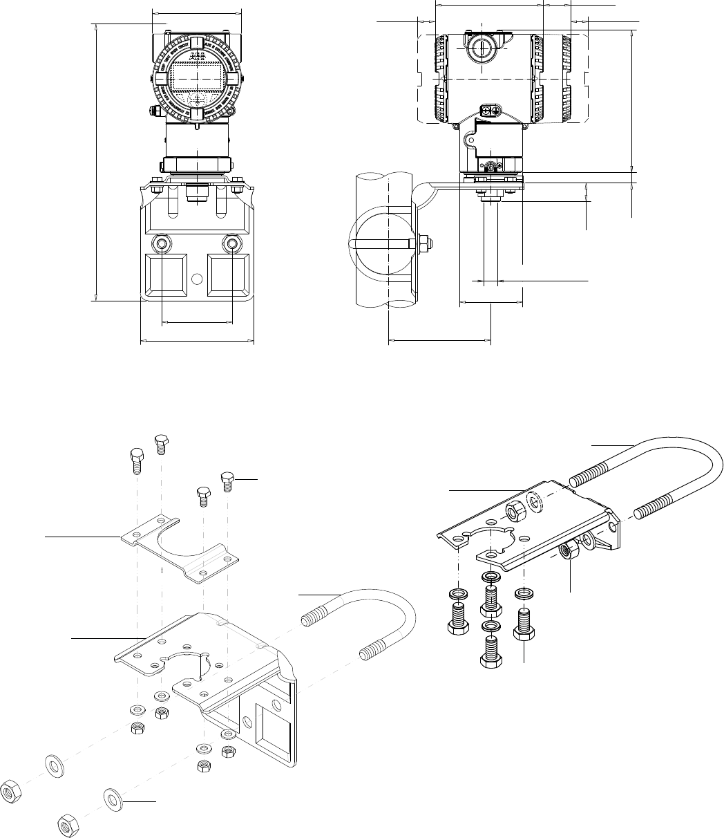
Figure 9: Differential Pressure Style transmitter with barrel housing and Kynar inserts installed on a vertical pipe with optional bracket (B2)
16 OI/266/WIHART-EN | 2600T Series Pressure transmitters
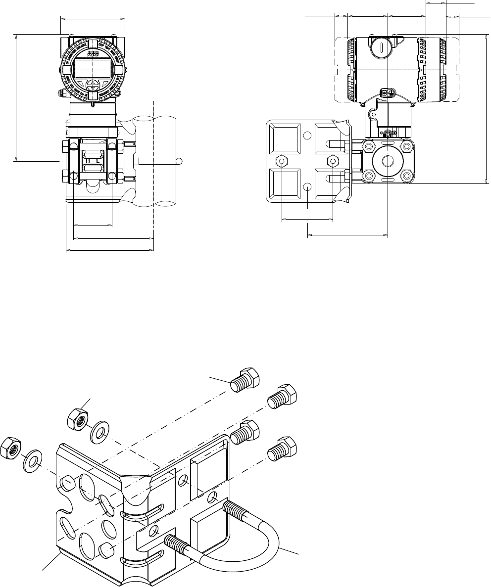
5 Mounting
Figure 11: Pipe and wall mounting bracket kit (B2)
1 – U-bolt
2 – U-bolt fixing bolt and washer
3 – Transmitter fixing bolts
4 – B2 bracket
54 (2.13)
123 (4.86)
113 (4.43)
179 (7.02)
91 (3.58)
29 (1.14)
18 (0.71)
18 (0.71) 55 (2.17)
58 (2.28)
210 (8.28)
113 (4.45)
72 (2.83)
Figure 10: Differential Pressure Style transmitter with barrel housing and Kynar inserts installed on a vertical pipe with optional bracket (B2)
5.5.2 B2 Pipe and wall mounting bracket details
All the bolts and nuts supplied are necessary for the installation on pipe. In case of panel or wall installation, the U-bolt and the
U-bolt nuts and washers will not have to be used.
The bolts for panel mounting are not within the scope of supply.
4
1
3
2
2600T Series Pressure transmitters | OI/266/WIHART-EN 17
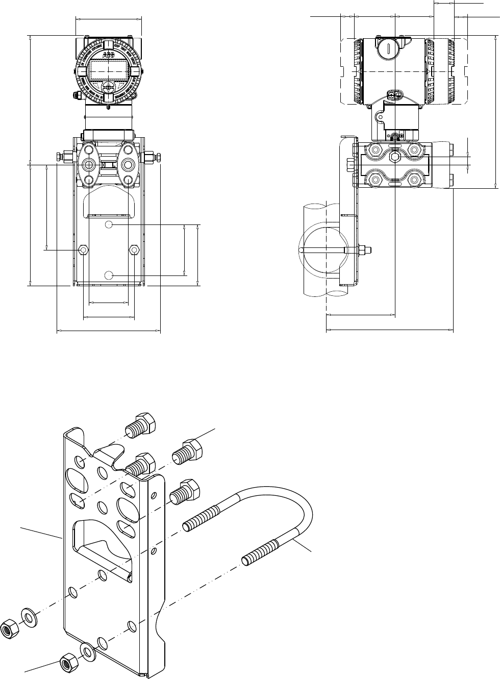
5 Mounting
142 (5.59)
(*)
70 (2.75)
179 (7.02)
91 (3.58)
166 (6.53)
70 (2.75)
84 (3.31)
117 (4.60)
29 (1.14)
18 (0.71)
18 (0.71)
11 (0.43)
210 (8.28)
58 (2.28) 55 (2.17)
95 (3.72)
174 (6.86)
Figure 12: Differential Pressure Style transmitter with barrel housing installed on a box pipe with optional bracket for SST housing (B5)
5.5.3 B5 Flat type bracket details
1 – U-bolt
2 – U-bolt fixing bolt and washer
3 – Transmitter fixing bolts
4 – B5 bracket
1
3
4
2
Figure 13: Flat type mounting bracket kit (B5)
18 OI/266/WIHART-EN | 2600T Series Pressure transmitters
5 Mounting
5.6 Mounting a P style pressure transmitter
(266H and 266N)
The pressure transmitter can be mounted directly on the
manifold.
A mounting bracket for wall or pipe mounting (2” pipe) is also
available as an accessory.
Ideally, the pressure transmitter should be mounted in a
vertical position to prevent subsequent zero shifts.
Figure 14: Model 266H or 266N High overload resistant P-Style transmitter with 1/2-14 NPT male process connection and barrel housing
installed on a 2”pipe with optional bracket (B1 carbon steel or B2 Stainless Steel 316L)
Important. If the transmitter is installed inclined with respect to the
vertical, the filling liquid exerts hydrostatic pressure on the
measuring diaphragm, resulting in a zero shift. In such an event, the
zero point can be corrected via the zero push-button or via the “set
PV to zero” command. Please refer to the [configuration section] for
further details. For transmitters without diaphragm seals the Vent /
Drain considerations below should be taken into consideration.
91 (3.58)
72 (2.83)
18 (0.71)
113 (4.45) 29 (1.14)
18 (0.71)
145 (5.71)
18 (0.71)
16 (0.63)
36 (1.42)
108 (4.25) 49 (1.93)
19 (0.75)
32 (1.26) width across
flats of exagon
18 (0.71)
113 (4.45) 29 (1.14)
18 (0.71)
145 (5.71)
91 (3.58)
18 (0.71)
16 (0.63)
108 (4.25)
72 (2.83)
39 (1.54)
49 (1.93)
54 (2.13)
1/2 - 14 NPT
32 (1.26) width across
flats of exagon
Figure 15: Model 266H or 266N High overload resistant P-Style transmitter with 1/2-14 NPT female process connection and barrel
housing installed on a 2”pipe with optional bracket (B1 carbon steel or B2 Stainless Steel 316L)
2600T Series Pressure transmitters | OI/266/WIHART-EN 19
5 Mounting
29 (1.14)
18 (0.71) 18 (0.71)
145 (5.71)
19 (0.74)
Ø65 (2.56)
91 (3.58)
12 (0.45)
105 (4.12)
116 (4.57)
72 (2.83)
283 (11.12)
113 (4.45)
23 (0.9) width across
flats of exagon
Figure 16: Model 266H or 266N High overload resistant P-Style transmitter with sensor Z with barrel housing installed on a 2”pipe with
optional bracket (B1 carbon steel or B2 Stainless Steel 316L)
5.6.1 B1 and B2 Barrel housing bracket details
Figure 17: Pipe and wall mounting bracket kits for P style transmitter with Barrel housing
1
3
4
2
1 – U-bolt
2 – U-bolt fixing washers and nuts
3 – Transmitter fixing bolts
4 – B1 or B2 bracket
5 – Fitting adapter (supplied with 266HSH)
1
2
3
4
5
20 OI/266/WIHART-EN | 2600T Series Pressure transmitters
5 Mounting
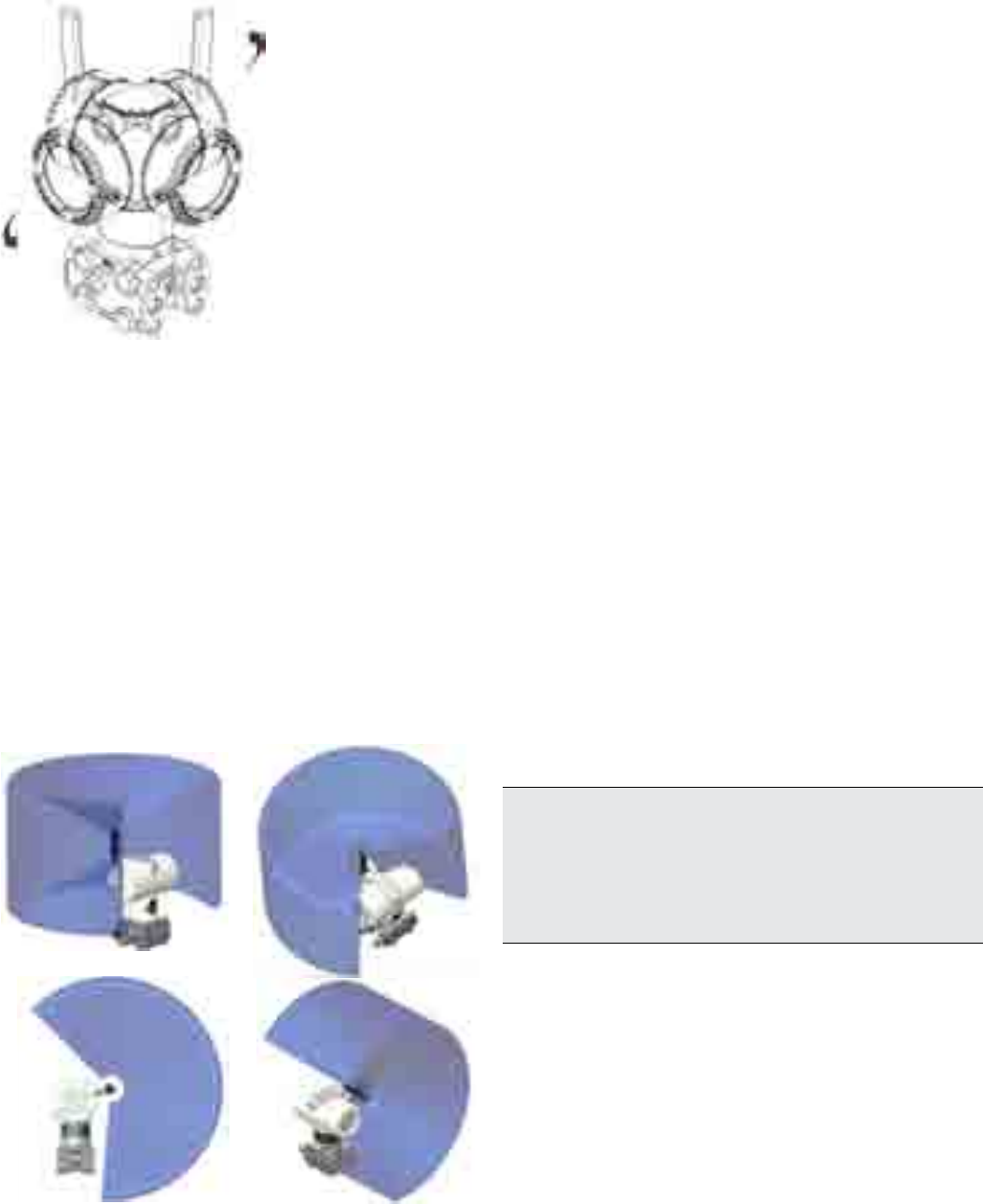
5.7 Transmitter housing rotation
To improve field access to the wiring or the visibility of the
optional LCD meter, the transmitter housing may be rotated
through 360° and fixed in any position. A stop prevents the
housing from being turned too far. In order to proceed with
housing rotation, the housing stop tang-screw has to be
unscrewed by approximately 1 rotation (do not pull it out) and,
once the desired position has been reached, retightened.
Figure 18: Housing rotation
5.8 Integral display rotation
In case an optional integral display meter is installed, it is
possible to mount the display in four different positions rotated
clockwise or counterclockwise with 90° steps. To rotate the
LCD, simply open the windowed cover (Hazardous area
prescriptions must be respected), pull-out the display housing
from the communication board.. Reposition the LCD connector
according to the new desired position. Push back the LCD
module on the communication board. Be sure that the 4 plastic
fixing locks are properly in place.
5.9 Antenna rotation
Usually the antenna should be turned into a vertical or
horizontal positions. The antenna must not be rotated more
than 360° in order to not prevent HF wires inside the
transmitter from damaging. Please refer to the pictures below
to identify wireless signal coverage areas.
5.10 Impulse piping connection for standard
instruments
In order for the pipes to be laid correctly, the following points
must be observed:
— The measuring pipes must be as short as possible and
free from sharp bends.
— Lay the impulse piping in such a way that no deposits
accumulate in them. Gradients should not be less than
approx. 8% (ascending or descending).
— The measuring pipes should be blown through with
compressed air or, better yet, flushed through with the
measuring medium before connection.
— Where a fluid/vaporous measuring medium is being used,
the liquid in both measuring pipes must be at the same
level. If a separating liquid is being used, both measuring
pipes must be filled to the same level (266Dx).
— Although it is not absolutely necessary to use balancing
vessels with vaporous measuring media, measures must
be taken to prevent steam entering the measuring
chambers of the measuring equipment (266Dx).
— It may be necessary to use condensate vessels, etc., with
small spans and vaporous measuring media (266Dx).
— If using condensate vessels (steam measurement), you
should ensure that the vessels are at the same elevation
in the differential pressure piping (266Dx).
— As far as possible, keep both impulse lines at the same
temperature (266Dx).
— Completely depressurize the impulse lines if the medium
is a fluid.
— Lay the impulse lines in such a way that gas bubbles
(when measuring fluids) or condensate (when measuring
gases) can flow back into the process line.
— Ensure that the impulse lines are connected correctly
(High and Low pressure sides connected to measuring
equipment, seals...).
— Make sure the connection is tight.
— Lay the impulse line in such a way that prevents the
medium from being blown out over the measuring
equipment.
Caution. Process leaks may cause harm or result in death. Install
and tighten process connectors and all accessories (including
manifolds) before applying pressure. In case of toxic or otherwise
dangerous process fluid, take any precautions as recommended in
the relevant Material Safety Data Sheet when draining or venting.
Use only a 12 mm (15/32“) hexagonal spanner to tighten the
bracket bolts.
Figure 19: Signal coverage according to antenna rotation
2600T Series Pressure transmitters | OI/266/WIHART-EN 21
5 Mounting
Figure 21: Kynar insert
Figure 20: Adapter
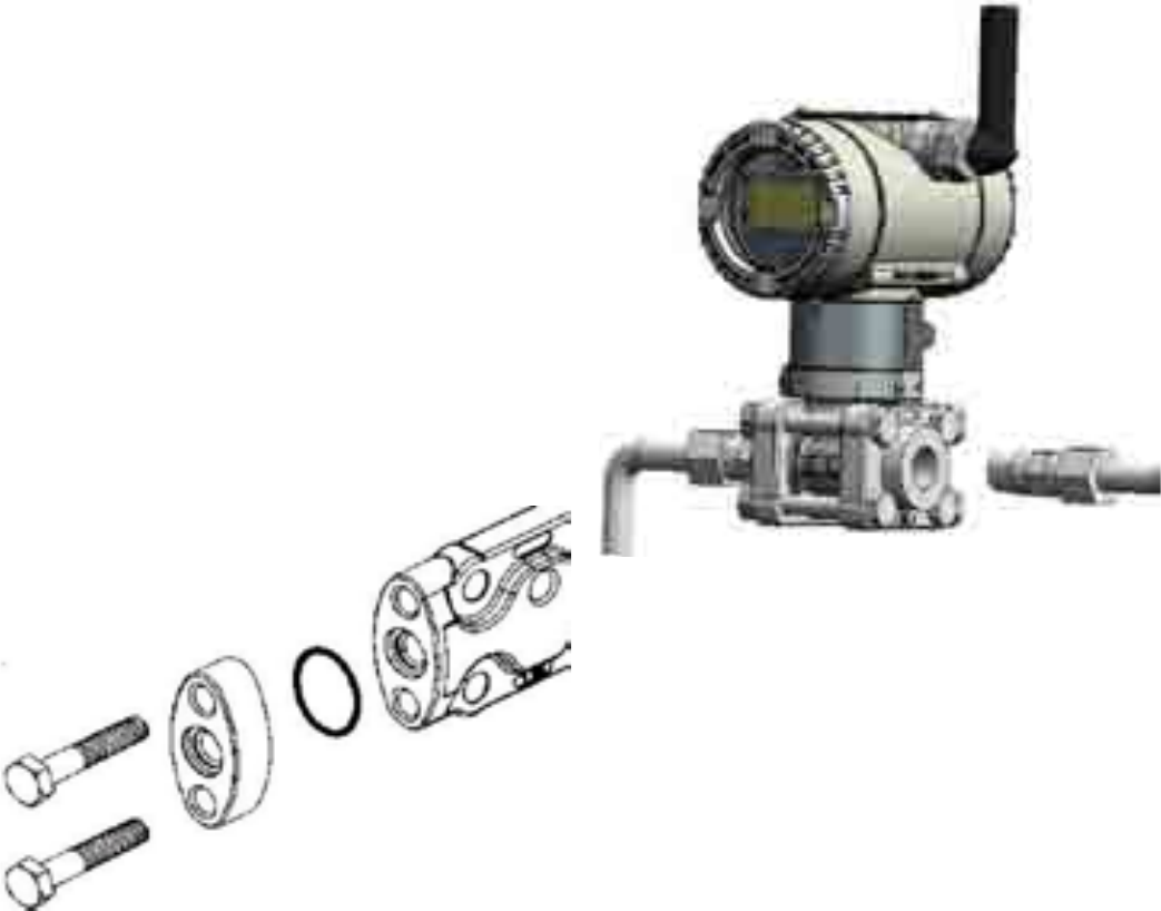
5.11 Process connections considerations
266 differential pressure transmitter process connections on
the transmitter flange are 1/4 - 18 NPT, with a centers distance
of 54mm (2.13in) between the connections. The process
connections on the transmitter flange are on centers to allow
direct mounting to a three-valve or five-valve manifold.
Flange adapter unions with 1/2 - 14 NPT connections are
available as an option. Rotate one or both of the flange
adapters to attain connection centers of 51mm (2.01in), 54mm
(2.13in) or 57mm (2.24in).
To install adapters, perform the following procedure:
1. Position the adapters with the O-ring in place.
2. Bolt the adapters to the transmitter using the bolts
supplied.
3. Tighten the bolts to a torque value of 25Nm (stainless
steel bolts) or 15Nm (for Stainless steel NACE bolts).
For high static model (266DSH.x.H) tighten the bolts to a
torque value of 40 Nm (regardless of the material of the bolts
used). In case of PTFE O-rings, pretightening to 10Nm and final
tightening to 50 Nm.
5.12 Kynar inserts connection
When connecting Pressure transmitters equipped with kynar
inserts tighten the bolts to 15 Nm max.
22 OI/266/WIHART-EN | 2600T Series Pressure transmitters
5 Mounting
5.13 Installation recommendations
Impulse piping configuration depends on the specific
measurement application.
Important. Wireless pressure transmitters are equipped with
antenna and extended rear cover. The following installation
sketches are shown for convenience only. Please consider the
antenna and the battery seat while planning installation schemes.
5.13.1 Steam (condensable vapor) or clean liquids flow
measurement
— Place taps to the side of the line.
— Mount beside or below the taps.
— Mount the drain/vent valve upward.
— In case of steam application fill the vertical section of the
connecting lines with a compatible fluid through the filling
tees.
The process fluid must enter the transmitter primary:
1. Open equalizing valve (C)
2. Close low pressure (B) and high pressure (A) valves .
3. Open gate valves
4. Slowly open high pressure (A) valve to admit process fluid
to both sides of primary.
5. Vent or drain the primary unit and then close the valves.
6. Open the (B) valve and close the equalizing valve.
Figure 22: Steam or clean liquid flow measurement
(transmitter and manifold)
Figure 23: Gas or liquid flow measurement (transmitter and manifold)
5.13.2 Gas or liquid (with solids in suspension) flow
measurement
— Place the taps to the top or side of the line.
— Mount the transmitter above the taps.
The process fluid must enter the transmitter primary:
1. Open equalizing valve (C)
2. Close low pressure (B) and high pressure (A) valves .
3. Open gate valves
4. Slowly open high pressure (A) valve to admit process fluid
to both sides of primary.
5. Vent or drain the primary unit and then close the valves.
6. Open the (B) valve and close the equalizing valve.
Caution. Manifolds can be supplied both mounted on pressure
transmitters and loose. In case of integral mounting, consider that:
— All adjustments should be carried out by qualified personnel with
the valve without pressure.
— End connections must not be removed from the body.
— Do not use handle wrenches or extensions to operate the
valves.
— Head units must not be removed once installed.
— Do not cover or remove body marking.
Important. The maximum working temperature of the whole
assembly (manifold and instrument) corresponds to the temperature
limit of the pressure transmitter.
Important. When the manifold is assembled to a 2600T pressure
transmitter with NACE compliance A4-50 Stainless Steel bolts
(available on request), please note that the maximum working
pressure is limited to 210 bar (3045 psi).
2600T Series Pressure transmitters | OI/266/WIHART-EN 23
5 Mounting
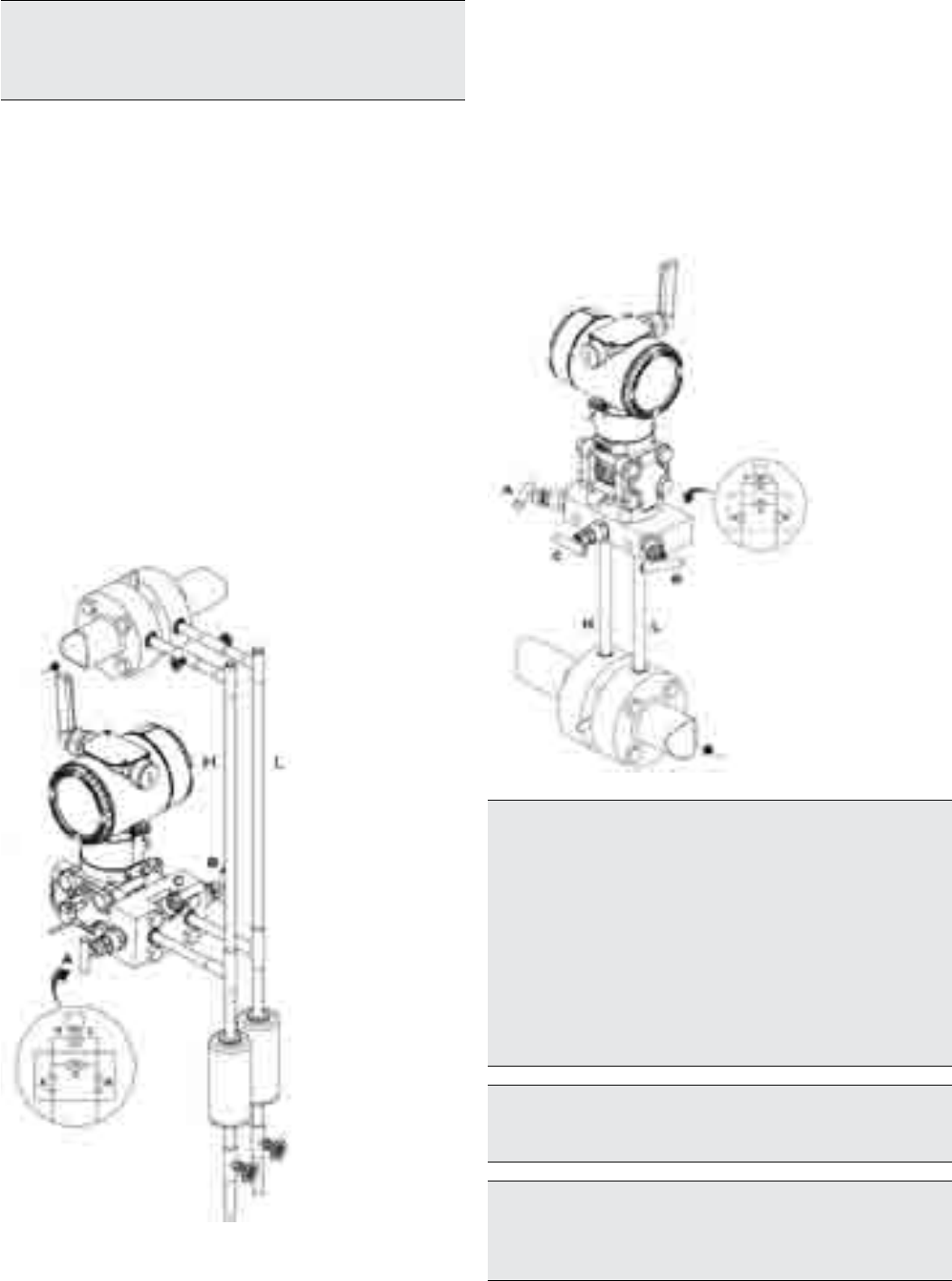
5.13.3 Liquid level measurements on closed tanks and
non condensable fluids (dry leg)
— Mount the transmitter at the same height or below the
lowest level to be measured.
— Connect the + (H) side of the transmitter to the bottom of
the tank.
— Connect the - (L) side of the transmitter to the upper part
of the tank, above the maximum level of the tank.
5.13.4 Liquid level measurement with closed tanks and
condensable fluids (wet leg)
— Mount the transmitter at the same height or below the
lowest level to be measured.
— Connect the + (H) side of the transmitter to the bottom of
the tank.
— Connect the - (L) side of the transmitter to the upper part
of the tank.
— Fill the vertical section of the connecting line to the upper
part of the tank with a compatible liquid through the
dedicated filling tee.
Figure 24: Level measurement on closed tank with dry leg
Figure 25: Level measurement on closed tank with wet leg
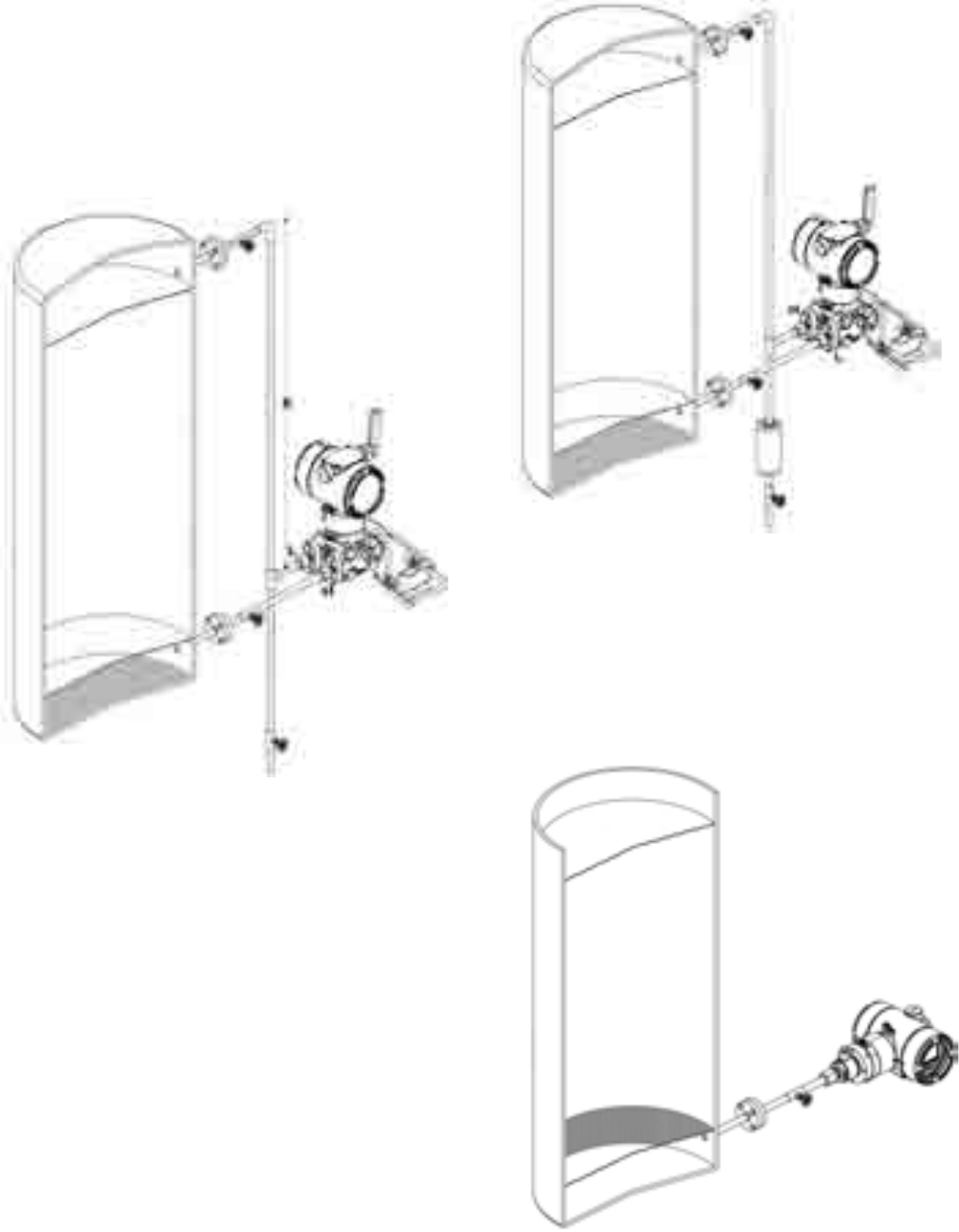
5.13.5 Liquid level measurement with open tanks
— Mount the transmitter at the same height or below the
lowest level to be measured.
— Connect the + (H) side to the bottom of the tank.
— Vent the “–” (L) side of the transmitter to the atmosphere
(in this case a gauge pressure is shown; the (L) side is
already vented to the atmosphere).
Figure 26: Level measurement on open tank with P style transmitter
24 OI/266/WIHART-EN | 2600T Series Pressure transmitters
5 Mounting
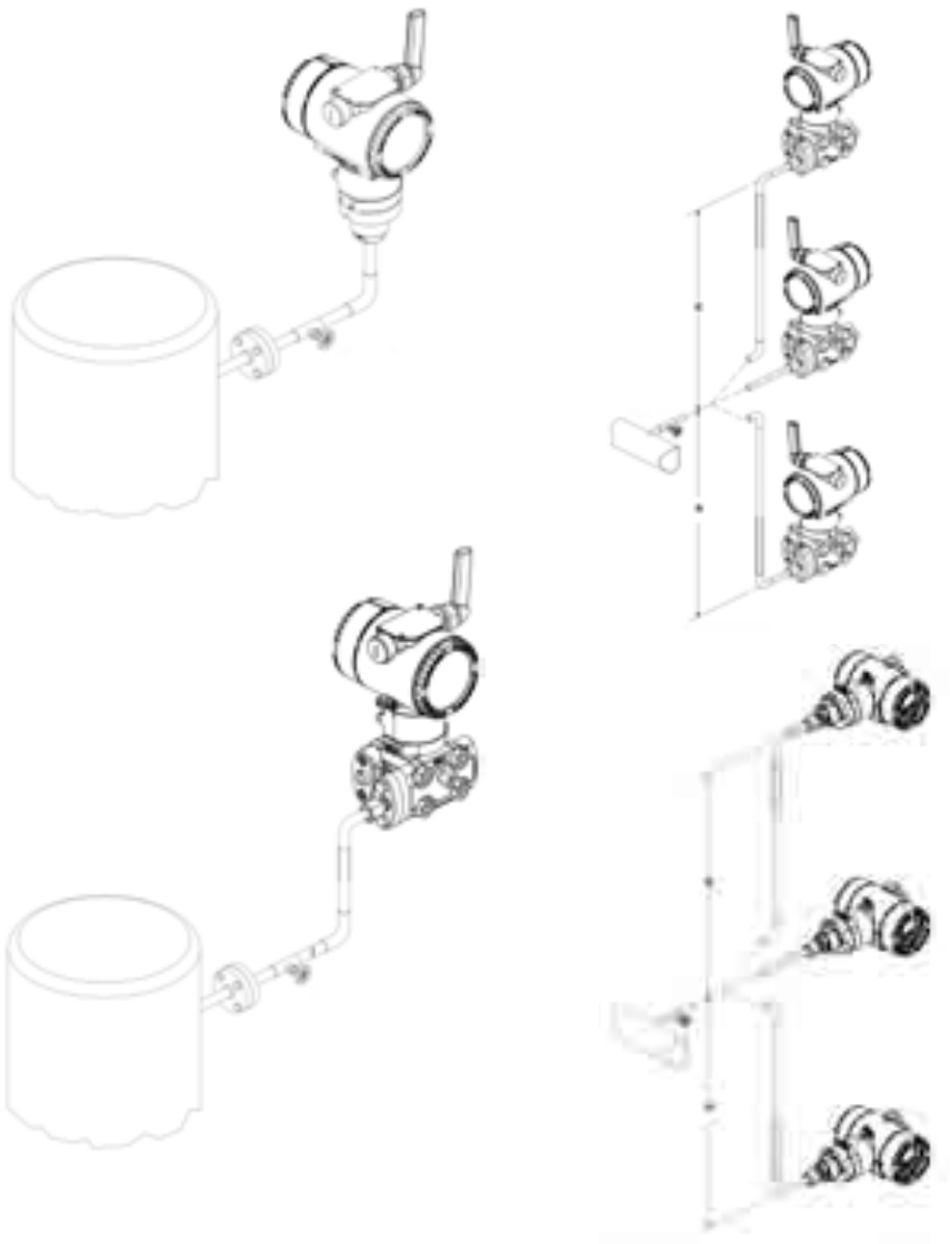
5.13.6 Pressure or absolute pressure measurement of a
tank
— Place the taps in the upper part of the tank.
— Mount the transmitter above the elevation of the process
tap (both pressure and differential pressure transmitter can
be used).
— Connect the transmitter to the tank.
Figure 27: Gauge or absolute pressure measurement on a tank
5.13.7 Pressure or absolute pressure measurement of a
liquid in a pipe
— Place the tap at the side of the line.
— Mount the transmitter (both pressure and differential
pressure transmitters) beside or below the tap for clean
fluids, above the tap for dirty fluids.
— Connect the + (H) side of the transmitter to the pipe.
Figure 28: Gauge or absolute pressure measurement of a liquid in
a pipe
2600T Series Pressure transmitters | OI/266/WIHART-EN 25
5 Mounting
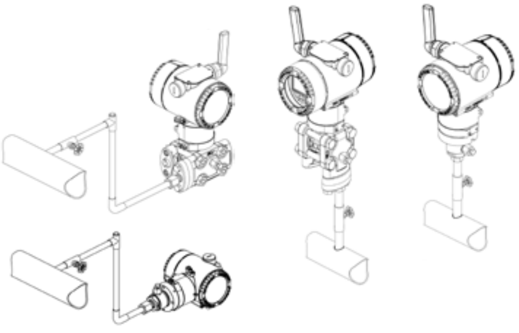
5.13.8 Pressure or absolute pressure measurement of a
condensable vapor in a pipe
— Place the tap at the side of the line.
— Mount the transmitter (both pressure and differential
pressure transmitter) below the tap.
— Connect the + (H) side of the transmitter to the pipe.
— Fill the vertical section of the connecting line to the tap
with a compatible liquid through the dedicated filling tee.
Figure 29: Gauge or absolute pressure measurement of
condensable vapor
5.13.9 Pressure or absolute pressure measurement of a
gas in a pipe
— Place the tap at the top or side of the line.
— Mount the transmitter (both pressure and differential
pressure transmitter) beside or above the tap.
— Connect the transmitter to the pipe.
Figure 30: Gauge or absolute pressure measurement of gas in a pipe
26 OI/266/WIHART-EN | 2600T Series Pressure transmitters
6 Transmitter connection
6 Transmitter connection
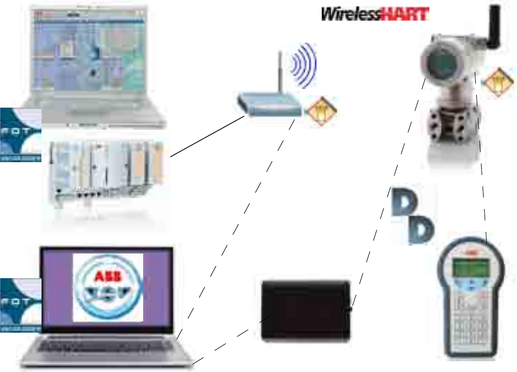
6.1 Network architecture
The picture above represents a generic wireless architecture. Dashed lines are temporarily wired connections.
Wireless devices can communicate both with wired or wireless tools. Wired tools can be: Asset Vision Basic 2 and Hand-held
terminal 3 (which has to run HART 7 protocol).
Field devices can communicate with Asset Vision Basic wirelessly through the Gateway connected via Ethernet TCP/IP 1.
The Gateway communicates to the DCS (Distributed Control System) via Modbus RS485 4.
6.2 Design and function
Wireless HART transmitters provide an FSK maintenance port too, compatible with existing tools such as modems and handheld
terminals with the purpose of configuration and maintenance. Anyway, its main communication interface is wireless. The same
protocol is used to communicate with a wireless HART compatible gateway. The gateway provides different kinds of wired
interfaces and protocols such as RS-485 or Ethernet.
The transmitters can be configured, polled, and tested using a DTM or an EDD via both, the wired and the wireless interface.
DCS
HART 7
Ethernet TC/IP
Modbus RS485
Asset Vision Basic
HART modem
Hand-held terminal
Gateway
1
2
3
4
2600T Series Pressure transmitters | OI/266/WIHART-EN 27
6 Transmitter connection
Important.
HART hand-held communicator may be connected
at any termination point in the loop. No need of 250 ohms
resistance for communication purposes.
6.4 Supply requirement
Pressure transmitter power supply is granted by a 3.6V size ‘D’
battery. Standard supplied battery is a Lithium-thionyl chloride
cell certified for Hazardous Areas.
6.5 Powering the transmitter on
Follow these steps to power the transmitter on:
— Remove the temporary plastic cap from one of the two
electrical connection ports located at both sides in the
upper part of the transmitter housing.
— This connection port has a M20 threads. Dedicated plug
has to be fitted to this port to comply with plant standards.
Important.
266 Pressure Transmitter is certified IP67. To
maintain the IP67 certification rating, it is necessary to select
the dedicated plug.
— Remove the housing cover of the “field terminals” side.
See the indication engraved on one side of the housing.
— Remove the battery pull-tab grabbing it firmly and pulling
it completely outside from its slot. This will allow the cell to
make contact with the electronic module.
Note.
266 WiPressure battery is manufactured by TADIRAN
Batteries GmbH (manufacturer code SL 2780)
— Before installing the huosing cover, check whether the
display is working or not. If yes, put back the housing
cover, turn it to seat O-ring into the housing and then
continue to hand tighten until the cover contacts the
housing metal-to-metal.
6.6 Protective Grounding
Pressure transmitter housing should be grounded or earthed in
accordance with national and local electrical codes. Ground
connection is mandatory for surge protector equipped devices
in order to ensure proper functioning.
Protective grounding terminals (PE) are available outside and/or
inside the housing of the transmitter. Both ground terminals are
electrically connected and it up to the user to decide which one
to use. The most effective transmitter case grounding method
is direct connection to earth ground with impedance equal or
less of 5 ohm.
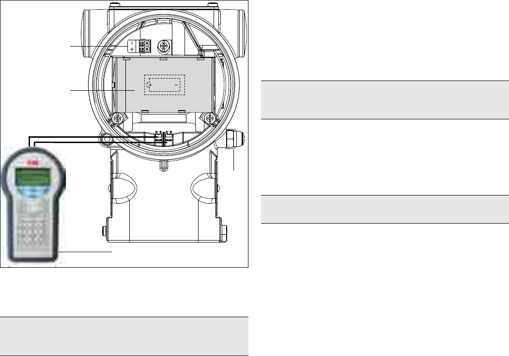
6.3 HART
Figure 31: HART transmitter connection scheme
2
3
4
1
1 Handheld communicator | 2 External ground termination
point | 3 Battery | 4 Fast connection for harvesting unit
28 OI/266/WIHART-EN | 2600T Series Pressure transmitters
7 Commissioning
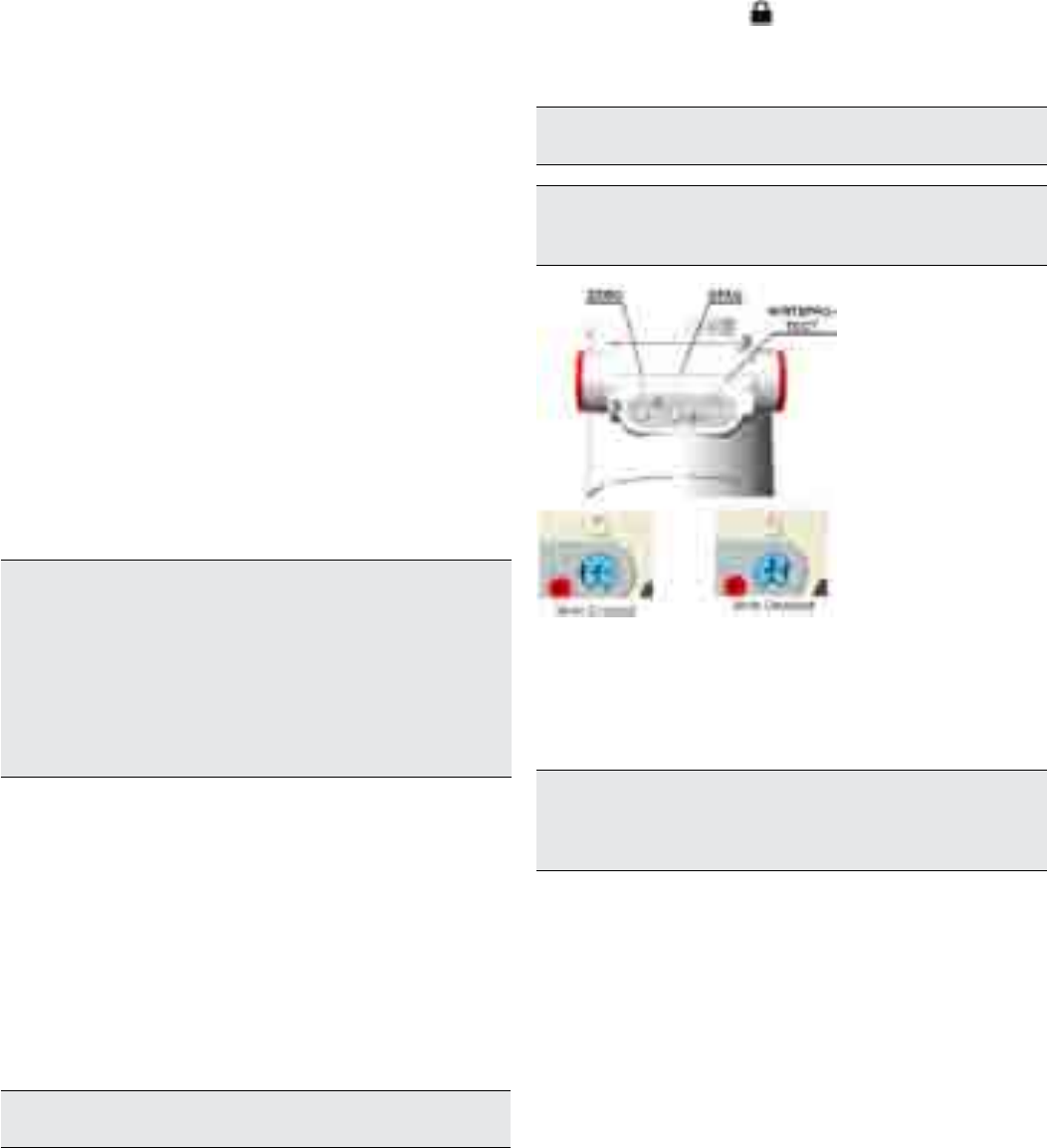
The write protection function can be performed as follows:
— Remove the ID (see figure 3 at chapter 4) by releasing the
holding screw lying on the bottom left corner.
— Turn ON device LCD (if installed) by pressing “Z” button and
check if the lock icon is displayed.
— Use a suitable screwdriver to press the switch down fully.
— Then turn the switch clockwise by 90°.
Important. To deactivate the switch, push it down slightly and then
turn counterclockwise by 90°.
Important. To activate or de-activate the Write Protection function,
instrument shall be live. To make instrument go live, press “Z”
button for two seconds and wait for the display to turn on.
7 Commissioning
Once the transmitter has been installed, it is put into operation
by enabling the battery. Check the following before switching
on the operating voltage:
— Process connections
— The impulse line/s and the measuring chamber of the
measuring equipment must be completely filled with the
measuring medium.
The transmitter can then be put into operation. To do this, the
shut-off valves must be actuated in the following sequence (in
the default setting, all valves are closed).
(Differential models) 266Dx
— Open the shut-off valves on the pressure tap connection
— Open the pressure equalization valve of the manifold.
— Open the positive shut-off valve (on the manifold)
— Open the negative shut-off valve (on the manifold)
— Close the pressure equalization valve.
To put the transmitter out of operation, carry out the steps in
reverse order.
(Gauge & Absolute models) 266Hx, 266Nx
— Open the shut-off valve on the pressure tap connection
— Open the positive shut-off valve.
To put the transmitter out of operation, carry out the steps in
reverse order.
Important. Please be aware that the measuring equipment will
have been overloaded by the atmospheric pressure due to the long
periods of transport and storage involved.
For this reason, you will need to allow a starting time of approx. 30
minutes for 266Nx models after commissioning, until the sensor
has stabilized to such an extent that the specified accuracy can be
maintained.
Only passive devices or indicators may be connected.
7.1 Standard setting for normal operation
In order to prevent errors in flow rate measurements (266Dx) in
the lower range, it is possible to set a “cut off point” and/or a
“lin./sq. root transition point” via the optional LCD integral
displays with keypad or via external tools (DD file or DTM).
Unless otherwise specified, the “lin./sq. root transition point” is
set to 5% and the “cutoff” to 6% of the flow rate end value by
the manufacturer.
7.2 Standard setting for error detection (alarm)
External tools (DD file on handheld terminal or DTM) or the LCD
integral display (if installed) can be used to diagnose the error.
Important. A brief interruption in the power supply results in
initialization of the electronics (program restarts).
7.3 Write Protection
Write protection prevents the configuration data from being
overwritten by unauthorized users. If write protection is enabled,
the “Z” and “S” buttons are disabled. However, it is still possible
to read out the configuration data using communication tools
such as DTM or DD file on an handheld terminal. The control unit
may be leaded if required.
Figure 32: Write-protection pushbutton
7.4 Correcting the lower range value / zero shift
During installation of the transmitter, transmitter, zero shifts
caused by mounting (e.g., a slightly oblique mounting position
due to a remote seal, etc.) may occur; these must be corrected.
Important. The transmitter must have reached its operating
temperature (approx. 5 min. after startup, if the transmitter has
already reached the ambient temperature) in order to perform zero
shift correction. The correction must be made at dp (or p) = 0.
7.5 Correct the zero shift
The zero shift caused by the installation can be cancelled in
different ways:
— By acting on the external push button “Z” with live
instrument to align the PV digital output.
— By using the optional LCD with keypad (“Configuration of
the pressure transmitter using the integral LCD HMI” for
further information).
To correct the zero shift using “Z” push button:
— Wake up the instrument by pressing “Z” push button for
at least 2 seconds, then release it
— The HMI should Turn ON (if installed)
— Now press the Z again for at least 2 seconds
— When it is released the PV digital output is zeroed.

2600T Series Pressure transmitters | OI/266/WIHART-EN 29
7 Commissioning
7.6 Joining the network
In order to allow the wireless communication between
transmitter and gateway the transmitter shall join the network
configuring the relevant parameters Network ID and Join Key.
This initial basic setting can be done using:
— Asset Vision Basic via HART modem wired connected to
the device terminals
— Hand-held terminal wired connected to the device terminals
— The local HMI menu.
Usually 3 parameters should be set always during first
commissioning to alow a device to join a network:
— Network-ID. The network-id is the identifier of a network
and must be the same for all devices within the same
network including the gateway. There might be other
networks in parallel but they need to have a different
network-id. The network ID is a 16 bit wide number.
— Join-Key. The join key is important to authorize a device
joining the network. It serves for network security. The join
key can be the same for different networks. The join key is
a security relevant information and should protected as
such. Wireless HART allows individual join keys for the
wireless devices in the network what serves for higher
security but has also impact on maintenance effort. Not all
gateways may support individual join keys. The join key is
a set of four 32 bit wide numbers (128 bit in total).
— HART Long-TAG: This is human readable identifier of the
device in the network and is almost used by a getway to
build a device list (“live list”) of the network. The HART
Long-TAG shall be unique for every device in the network.
Some gateways notify when doubled long TAGs are
identified. As the HART Long-TAG is 32 characters long it
is suitable to serve as a unique identifier of a single device
in a whoile plant / installations and not just within the
wireless HART network. By default, 266 Pressure
Transmitters are delivered with a unique HART Long-TAG
containing part of the devices serial number and therefore
there is no need to set the HART Long-TAG. HART Long-
TAG is necessary for the communication via Ethernet TCP/
IP within the Asset Vision Basic projects
In case network ID and join key already match the settings of
the gateway e.g. due to prior configuration or default settings
are used, there is no need for any further adjustments. 266
WirelessHART will join a reachable network automatically.
Important.
For security reasons the join key cannot be read
back from the device as well as via the local LCD display.
Check the completion of the joinig operation with the used
pc-tool or looking at the HMI. The operation in completed once
the antenna simbol in the right top corner is fixed
Important.
To switch the HMI press for more than 2 second
the “Z” (zero) button. To reach the “Z” button, release the fixing
screw of the identification plate on the top of the instrument
housing.
7.7 Burst
7.7.1 Burst configuration
Once the device is in the newtwork the next step is to
configure the burst command. Optional burst communication
mode allows a single slave pressure transmiiter to continuously
broadcast a standard HART reply message at a certain,
defined, configured interval.
The operation can be done in in several ways:
— Wired
— Wireless
— Local display (HMI)
The device can be configured to send up to three bust
messages with interval between 2s and 60 minutes.
The configuarable message are the following HART commands
HART command Description
Command #1 Read Primary Variable
Command #2 Read P.V. Current and Percentage of Range
Command #3 Read Dynamic Variables and P.V. Current
Command #9 Read Device Variables with Status
Command #33 Read Device Variables
Command #48 Read Additional Transmitter Status
The burst mode can be set to trigger in differnet way
— Continuous: the burst message is published continuously
at the minimum update period.
— Window: the burst message is triggered when the source
value deviates more than the specific trigger value.
— Rising: the burst message is triggered when the source
value rises above the specified trigger value.
— Falling: the burst message is triggered when the source
value falls below the specified trigger value.
— On-change: the burst message is triggered when any
value in the message changes.
The message is normally sent at the configured update period.
Once the configured trigger conditions are sotisfied, the period
is set at the configured maximum update rate.
30 OI/266/WIHART-EN | 2600T Series Pressure transmitters
7 Commissioning
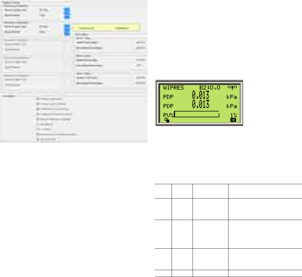
7.7. 2 B ur st s t atus
The device supports up to three Burst communications. Each
burst can be individually configured and enabled (ON) or
disabled (OFF). Depending on its configuration, each Burst
communication can have different possible Status that could be
helpful for detecting and evaluating possible critical or
anomalous situations between the gateway and the wireless
devices. If read from the wireless devices, some Burst Status
could give information about the wrong configuration of the
gateway and/or the wireless device installed. Burst status is
readible via HMI (if installed) or via dedicated section of the DTM
(see Commissioning by DTM).
Burst status have the following structure:
“Bn: X-Y” where:
— Bn is the Burst number as B1, B2 or B3
— X-Y represent two possible channels in negotiation with
the Network Manager (Gateway) for each Burst. These
letters can assume different values:
“O” = OFF
the associated burst has not been enabled.
If the device has joined the network bursts can be
enabled wirelessly, through wired DTM or using an
handheld terminal. In case the device has not yet
joined, burst enabling can be done through the wires
of the HART protocol or exploiting the DD file
(handheld terminal)
“N” = Negotiating phase
the associated burst is in the negotiation phase with
network manager (gateway) that is reserving the
correct resources bandwidth, timings, etc.
“R” = Reject
the associated burst setting has been refused by the
network manager due to some possible conflicts i.e:
bandwidth limitation or requested burst update period
too short. In case this value appears, review the
update period.
Figure 34: Burst B2 in OFF-OFF status
Figure 33: Burst visualization into DTM
“S” = Shutdown
the associated burst is in the shutdown phase. The
network manager is deleting all the resources
previously reserved at this burst. Until the burst is in
this condition, it cannot be reconfigured.
“A” = Active
the associated burst is Active/running,In this condition
the associated Burst is transmitting the selected
HART command or status to the Gateway according
to the update period.
The Bursts will be OK only when X-Y are displayed with
“A” - “A” or “A” - “O”.
When the selected “Burst Trigger” is set to “Continuous” there
is only one channel to be negotiated with the Network Manager
and in this case the second letter is not relevant (value fixed to
“O” - OFF). When the selected “Burst Trigger” is set to any
other event (Window, Rising, Falling or On-change), there are
two channels to be negotiated with the Network manager i.e.
one for the selected trigger event and the second for the
Maximum Update Period in case the trigger event never
occurs. In this case the X-Y represents the two channels. The
three bursts are displayed cyclically with an interval of 10
seconds.
7.7.3 Status byte
The Status byte is the fifth byte of any out value and represents
the Quality of the variable. Depending by which of the two
selections is active, the list of the possible Status can be the
following:
— Classic Status
Binary
Code
Decimal
Code Meaning Possible Cause
0x08 8More Device
Status Available
E.g. faluire state.
Additional status command shall be
sent for more details.
0x40 64 Poor accuracy
E.g. value is beyond rated pressure,
temperature outside range.
Additional status command shall be
sent for more details.
0xB0 176 Manaul / Fixed
E.g. simulad value or forced.
Additional status command shall be
sent for more details.
0xC0 192 Good Out of Service

2600T Series Pressure transmitters | OI/266/WIHART-EN 31
7 Commissioning
7.8 Commissioning by EDD-based HART Handheld
Terminal
The handheld terminal will allow you to set all the relevant
information to let the 266 WiPressure join a WirelessHART
network.
— Ensure the EDD has been loaded into the HART handheld
terminal.
— Connect the HART handheld configurator to the
instrument via the HART maintenance port.
— Set the handheld terminal to polling (multidrop) mode and
scan for devices. The 266 WiPressure has a default polling
address 1 (has per HART specification).
— Once connected you can edit the parameters and
configuration data.
Important
An EDD describes structure and type of device
parameters but as only a limited influence on how this
information is provided to the user. The following is an
example of how the EDD could be represented. Even the
parameter names may be slightly different as tools typically
use vendor specific libraries.
32 OI/266/WIHART-EN | 2600T Series Pressure transmitters
7 Commissioning
To commission 266 WiPressure using an EDD-based HART
handheld terminal, follow the below procedure:
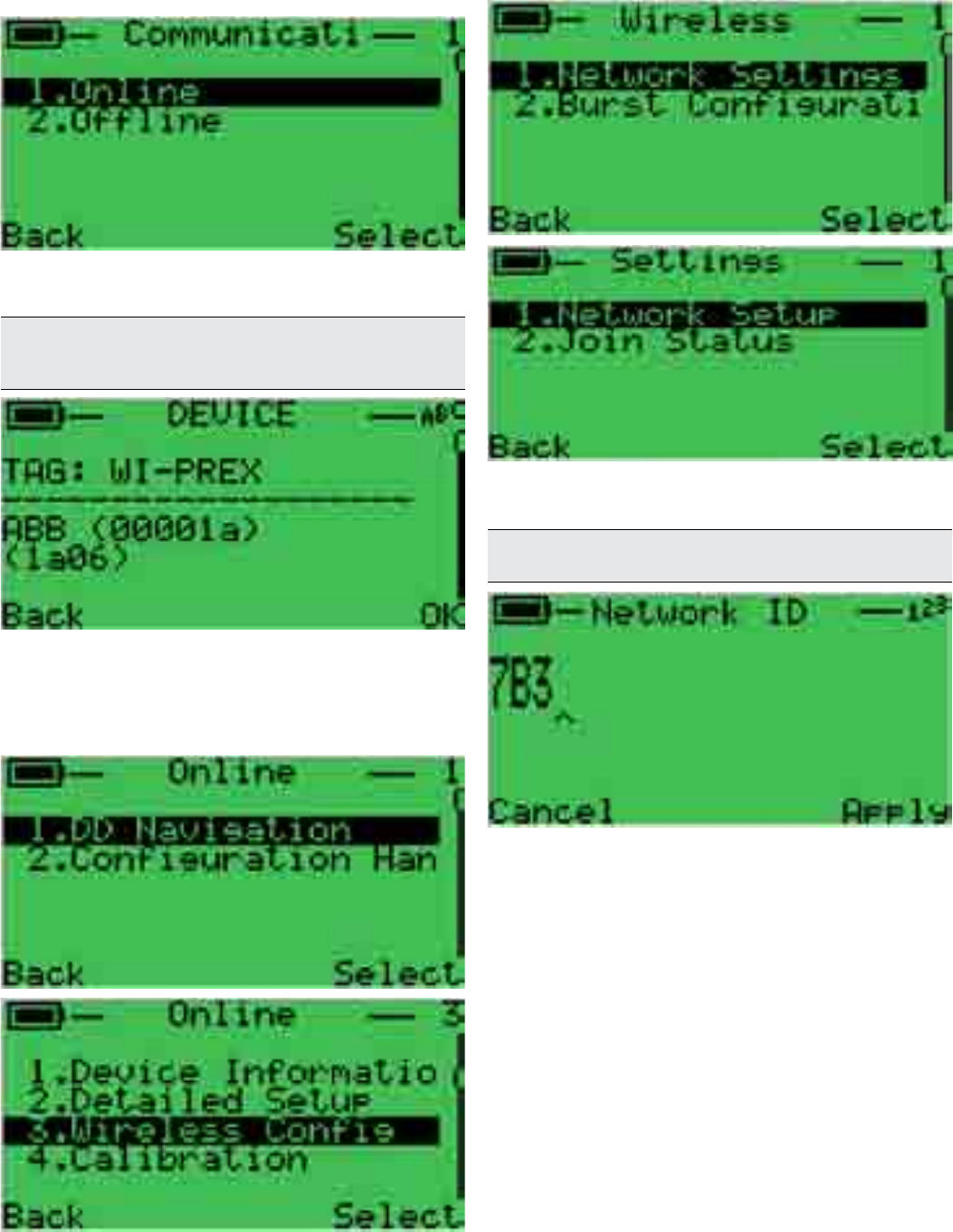
1. Connect the handhel terminal to the 266 WiPressure and
select “Communication” and then go “Online”.
2. After polling, the handheld terminal will show basic device
information such as TAG number, Manufacturer ID, Device
ID, DD revision and Device revision.
Important. Set the handheld terminal to poll in multidrop or on
address 1. 266WiPressure has default address 1 as per
WirelessHART specifications.
3. Select “DD navigation” and then “Wireless Config.” to start
configuring the instrument to join the network.
By using “DD navigation”, it is possible to edit instrument
measurement parameters as well as display etc. Please
refer to the next sub-chapter for information about 266
WiPressure DD structure.
5. To have 266WiPressure joining the network, there are
some parameters to set: Network ID and Join Key.
To reach these menus select “Network Settings” and then
“Network Setup”.
6. First point is Network ID. This parameter should be written
using hexadecimal numbering. After editing the default
value (0xABB), depress apply.
Important. Network ID can be configured according to customer
instructions at the factory.
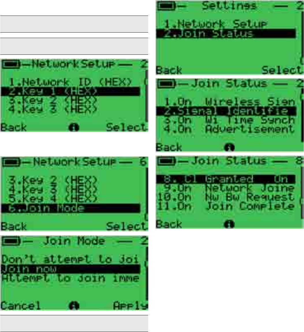
2600T Series Pressure transmitters | OI/266/WIHART-EN 33
7 Commissioning
7. Join Key is the second, essential data to insert.
Join Key is string of 32 (thirty two) characters divided into
4 (four) groups of 8 (eight) characters each. The four
groups are to be written into the 4 different menu entries
in hexadeciamal notation and allowed characters goes
from 0 to 9 and from A to F (capital letters only).
Note. Join Key entry is shown just once for convenience. Enter Join
Key from Key 1 (HEX) to Key 4 (HEX).
Important. For security reasons, Join Key cannot be read back
from the handheld terminal.
8. Select “Join Mode” (usually “Join Now”) and depress
“Apply”. With this operation, alll network parameters will
be sent to 266 WiPressure.
Note. Some handhelds or computer based tools require the Join
Key to be entered in decimal.
9. By selecting “Join Status” the handheld terminal will show
the progress of all actions necessary to have the 266
WiPressure joining the network and communicating with
the Network Manager (gateway).
34 OI/266/WIHART-EN | 2600T Series Pressure transmitters
7 Commissioning
7.8.1 EDD structure for 266 WiPressure
Device information
Device
Manufactorer
Model
Device Serial No
Device revision
HART Revision
Device Profile
Additional Device Revision
Hardware Revision
Software Revision
Measurement Point
Address
Write Protection
Communication tag
Date
Final Assembly Num
Descriptor
Message
Additional information
Long tag
Sensor type
Sensor revision
Read Sensor Sl number
Detailed Setup
General
Local Operations
Sensor Set-up
P-dP Sensor
Sensor Type
Upper Sensor Limit
Lower Sensor Limit
Minimum span
Static Pressure Sensor
Upper Sensor Limit
Lower Sensor Limit
Minimum span
Operational limit
Max Temperature limit
Min Temperature limit
Max Working Pressure
Unit
Temperature Unit
Static Pressure unit
Pressure Polarity
Pressure input [Direct]
Sensor materials
Basic Sensor materials
Diaphragm material
Filling Fluid
Process Connection High
Connection type
Flange Material
O-Ring Material
Blanking Plug
Process Connection Low
Connection type
Flange Material
O-Ring Material
Blanking Plug
P-dP
Process variable
Measured value
PdP Value
PV % range
Scaling
Value Input
Unit
PV LRV
PV URV
Process Pressure
Rerange
PV Bias
PdP Value
Set PV Val
Set PV to Zero
Bias Value
PV Bias Reset
Parallel Shift
Parallel Shift
Transfer Function
Transfer Function
Square Root Setting
Lin.Square root Point [%]
Cut Off
Output
Scaling
Unit
Custom Unit
Lower range Value
Upper range Value
Hart Mapping
PV is
SV is
TV is
QV is
Change SV mapping
Change TV mapping
Change QV mapping
Display
General
Display Revision
Contrast
Language
Display Setting
Display Mode
Line 1 view
Line 2 view
Bargraph view

2600T Series Pressure transmitters | OI/266/WIHART-EN 35
7 Commissioning
Wireless Config
Network Settings
Network setup
Network ID (HEX)
Key 1 (HEX)
Key 2 (HEX)
Key 3 (HEX)
Key 4 (HEX)
Join Mode
Join Status
Burst Configuration
Burst Message 1
Burst Message 1
Burst Mode
Burst command
Burst Msg Trigger Mode
Update period for burst message
Change Burst Config
Burst Message 2
Burst Message 2
Burst Mode
Burst command
Device Variables
Burst Msg Trigger Mode
Update period for burst message
Change Burst Config
Burst Message 3
Burst Message 3
Burst Mode
Burst command
Device Variables
Burst Msg Trigger Mode
Update period for burst message
Change Burst
Calibration
Pressure Sensor
Cal pressure
Full trim
Zero trim
Sensor temperature value
Sensor temperature trimming
Static Pressure
StaticPr Value
Zero trim
Low trim
Simulation
PdP Value
StaticPr value
Sensor Temp value
ScaledOut Value
Simulation
Process Variable
PdP Value
PdPstatus
StaticPr Value
StaticPr Status
sensorTemp value
sensorTemp status
scaledOut Value
scaledOut status
Diagnostics
Device Status
Diagnostics monitoring
Diag Simulation enable
Electronics
Sensor/Actuators
Installation/Start up
Process
Operating conditions
Wireless
Simulation
Diag Simulation Enable
Configuration
Electronics
Operating conditions
Sensor/Actuators
Process
Historic Info
Device
No. Power On
Total working time
Pressure variable logging
Min.Pressure value
Max.Pressure value
Reset
Sensor temperature logging
Min. temperature value
Max. temperature value
Reset
Static pressure logging
Min.Static Pressure value
Max.static Pressure value
Reset
Neighbor details
Wireless status
Wireless Mode
Join Retry timer
Join status
Neighbor count
Burst Status
Burst 1 status
Update rate service
Max Update rate service
Burst 2 status
Update rate service
Max Update rate service
Burst 3 status
Update rate service
Max Update rate service
Extras
Resets
Load Factory Settings
Lock/Unlock Device
Start Squawk
Note. Some entries may not be available due to instrument
configuration (i.e. static pressure entries not implemented for gauge
or absolute pressure transmitters).
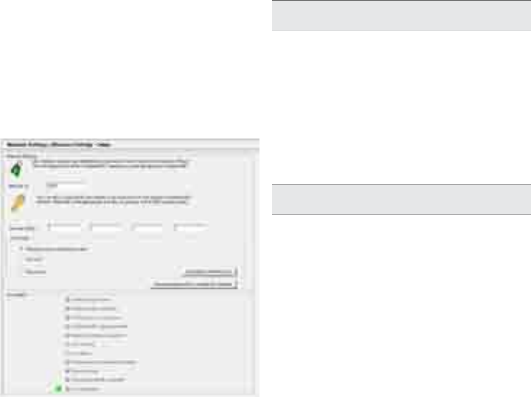
36 OI/266/WIHART-EN | 2600T Series Pressure transmitters
7 Commissioning
7.9 Commissioning by DTM
The 266WiPressure DTM gives access to all parameters and
information relevant to communication and device
commissioning. Once the device is taken into the wireless
network by the gateway the DTM can be used with the wired
but also with the wireless interface, depending of the
capabilities of FDT frame application and gateway.
Typically the connection to the gateway is via Ethernet. This
allows a remote access to the wireless HART network and the
266 WiPressure over intranet or Ethernet, depending on the
network policies. Components and tools provided or
recommended by ABB do not have limitation regarding the
communication interface.
Usually the network ID and join key needs to be set to allow a
wireless device to enter an existing network. The join key and
the network ID are also set in the gateway and must be the
same as that entered in the 266 WiPressure.
The following description assumes the device needs a change
of network parameters to join a network.
The DTM will have to be connected via a wired interface to the
266 WiPressure. After searching for the device and getting into
online mode the dialog Network Settings should be opened:
The sequence of the adjustments is as the position of the
parameters with the DTM dialog:
1. Network ID to be set in decimal notation within the DTM.
2. Join key to be set in hexadecimal notation
3. Join mode. Usually the option “Join now” is most suitable
to let the device enter the (new) network after download all
parameters described above.
The data on the bottom of the dialog gives status information
about the process of network join. Whenever a wireless HART
network is in the range of 266 WiPressure – even it does not
match its own network parameters - the “Wireless signal
found” flag is set. This is a pre-condition to join a network. The
266 WiPressure now tries to join the network and to establish a
connection to the wireless HART gateway.
A successful join phase is indicated by the “Join complete” flag
at the end. Depending of the network structure, size and
performance of wireless HART gateway and other devices in
the network it may take up to 60 minutes.
Important.
Some gateways need to switch on the “Active
Advertising” in order to support devices to join the network.
7.9.1 Network Diagnostics by DTM
One of the strengths of wireless HART networks is the
capability to automatically build a robust meshed structure. So
the wireless devices try to connect to neighbours in order to
get multiple paths for any telegram.
Powerful network diagnostics of 266 WiPressure automatically
checks the network transmission quality to and from the device
itself.DTM gives visibility about signal strenght for at maximum
five neighbour devices showing their specific link.
Signal strength is returned as a computed value which includes
signal level, retries required etc.
Important.
In a proper and robust network, each wireless
device should have at least three neighbours.
Figure 35: Burst B2 in OFF-OFF status
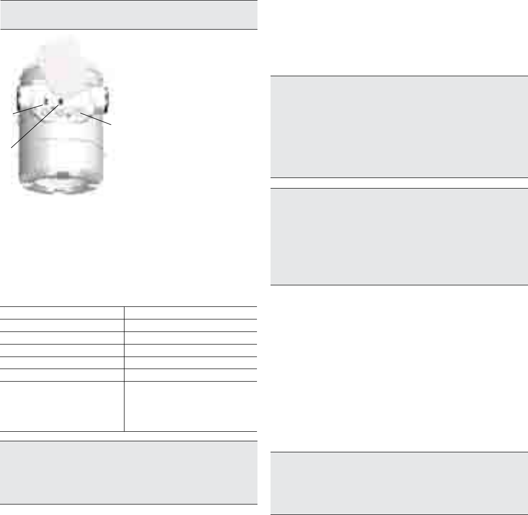
2600T Series Pressure transmitters | OI/266/WIHART-EN 37
8 Operation
8 Operation
8.1 Local push buttons functionality
266 transmitters allow local adjustments via the on-board non
intrusive push buttons, when selected. The push buttons are
located under the identification nameplate. To gain access to
the local adjustments release the fixing screws of the
nameplate and rotate clockwise the identification plate.
Warning - Potential damage to parts. Operating the control
buttons with a magnetic screwdriver is not permitted.
11 - Identification nameplate
2 - Zero pushbutton
3 - Span pushbutton
4 - Write-protection
pushbutton
4
3
2
Figure 36: Pushbutton functionalities
8.2 Factory settings
Transmitters are calibrated at the factory to the customer’s
specified measuring range. The calibrated range is provided
on the name plate whereas the tag number on the additional
tag plate. The calibrated range and tag number are provided
on the name plate. If this data has not been specified, the
transmitter will be delivered with the following configuration:
Parameter Factory setting
Lower Range Value (LRV) Zero
Upper Range Value (URV) Upper Range Limit (URL)
Output transfer function Linear
Optional LCD HMI scale 1 line PV and output signal bargraph
Network ID HEX (DEC) 0XABB (2747)
Join Key HEX
57495245
4C455353
4649454C
444B4559
Important. Every of the configurable parameters here on the left can
easily be modified either via the optional LCD HMI, with an HART
handheld terminal or a compatible software solution. Information
regarding flange type and material, O-ring materials, and filling liquid
type is stored inside the non-volatile memory of the device.
8.3 Configuration types
Pressure transmitters can be configured as follows:
— via Zero and Span push buttons (LRV and URV).
— using the integral LCD HMI with keypad (menu-controlled)
— with a handheld terminal
— using a PC/laptop via the graphical user interface (DTM)
8.4 Configuring the transmitter without an integral
LCD HMI
The “lower range value” and “span” parameters can be set
directly on the transmitter using the external push buttons.
The transmitter has been calibrated by the manufacturer based
on the order information. The tag plate contains information on
the “lower range value” and “upper range value” set. In general,
the following applies:
To change the transmitter ranging apply the pressure for the
“lower range value” and “upper range value” to the measuring
equipment. Make sure that the measuring limits are not
exceeded.
Important. Reducing station with adjustable pressure and
reference displays can be used as pressure generators.
When making the connection, please ensure that there are no
residual fluids (for gaseous testing materials) or air bubbles (for fluid
testing materials) in the impulse lines, since these can lead to errors
during inspection. Any potential measuring error for the pressure
generator should be at least three times smaller than the desired
measuring error for the transmitter.
Important. In case of the 266 transmitter for absolute pressure
(266Nx) with a measuring range less than or equal 650 mbar abs.,
please be aware that the measuring equipment will have been
overloaded by the atmospheric pressure due to the long periods of
transport and storage involved. For this reason, you will need to
allow a starting time of approx. 30 minutes for 266Nx model, until
the sensor has stabilized to such an extent that the specified
accuracy can be maintained.
8.5 LRV and URV configuration
— Apply the pressure for the “lower range value” and wait
approx. 30 s until it has stabilized.
— Press the “Z” button to wake the instrument up and then
keep “Z” button pressed in order to assign the LRV.
— Apply the pressure for the “upper range value” and wait
approx. 30 s until it has stabilized.
— Press the “S” button to assign the URV.
— Record the new settings. The respective parameter will be
stored in the non-volatile memory 10 seconds after the “Z”
or “S” buttons are last pressed.
Important. This configuration procedure does not affect the
physical process pressure (PV value) also shown on the digital
display or user interface. To avoid potential discrepancies, you can
use follow the procedure below. After performing a correction, you
must check the device configuration.
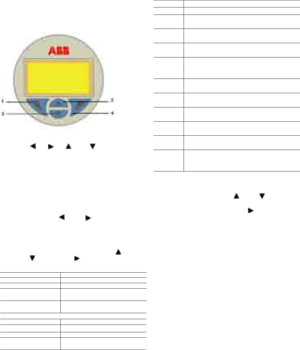
38 OI/266/WIHART-EN | 2600T Series Pressure transmitters
8 Operation
8.6 Configuration of the pressure transmitter using
the optional integral LCD HMI with keypad (menu-
controlled)
The integral LCD HMI is connected on the 266 communication
board. It can be used to visualize the process measured
variables as well as to configure the display and the transmitter.
In addition, diagnostic information is provided. To access the
functionality of the HMI an activation procedure needs to be
carried out. The keypad activation procedure is different
between the TTG (Trough The Glass) version and the
conventional HMI.
Figure 37: Display keypad
The keys (1) , (4) , (2) and (3) are available for the
menu-controlled configuration.
— The menu / submenu name is displayed above in the LCD
display.
— The number/line of the currently selected menu item is
displayed in the upper right of the LCD display.
— A scroll bar is located on the right edge of the LCD
display which shows the relative position of the currently
selected menu item within the menu.
— Both of the keys (1) and (4) can have various
functions.
The meaning of these buttons is displayed below in the
LCD display above the respective button.
— You can browse through the menu or select a number
within a parameter value using both keys (2)
and (3) . The button (4) selects the desired menu
item.
Button (1) functionalities Meaning
Exit Exit menu
Back Back one submenu
Cancel Exit without saving the selected parameter
value
Next Select next position for entering numerical
values or letters
Button (4) functionalities Meaning
Select Select submenu/parameter
Edit Edit parameter
Ok Save selected parameter and display
stored parameter value
8.7 HMI as feedback of the local push button
operations
As consequence of the operations described in the section 8.2,
when the Z or S buttons are released, the feedback of the
executed operation is displayed in the bottom of the LCD
(same position as per diagnostic messages):
Message Description
! Oper Done The push button operation has been successfully executed
! Proc Too
Low
The Pressure measured in input is too low and not
acceptable for the requested operation
! Proc Too
High
The Pressure measured in input is too high and not
acceptable for the requested operation
! New URV
Error
The Zero (Z) operation cannot be accepted because the
URV would be shifted outside the Upper Sensor limit
! Span Error
The Span (S) operation cannot be accepted because the
new URV would be too close to the LRV and their
difference lower than the Minimum Span value
! Oper
Disabled
The push button operation has been refused because the
Write Protection is enabled.
! LRV Too
Low
New LRV is too low and not acceptable for the requested
operation
LRV Too
High
New LRV is high low and not acceptable for the requested
operation
URV Too
Low
New URV is too low and not acceptable for the requested
operation
URV Too
High
New URV is high low and not acceptable for the requested
operation
Armed
Device is armed to accept HART command 73 “Find
Device”. This message can be triggered only during the
device wakeup operation
8.8 HMI menu structure
The HMI menu is divided in the following sections which can be
selected by acting on the keys (2) and (3) , once on the
display the desired sub-menu icon will be visualized, confirm
your selection with the [SELECT] key (4) .
Follow the instruction on the screen to perform the
configuration of the different parameters.
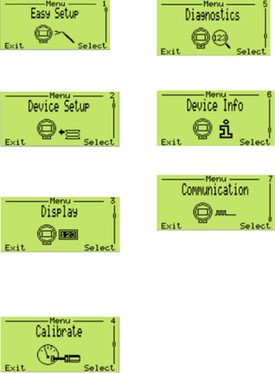
2600T Series Pressure transmitters | OI/266/WIHART-EN 39
8 Operation
This menu allows the verification and the parameterization of
the basic configuration of the 266 pressure transmitter. The
menu driven structure will guide you to the setting of Join Key,
Network ID and tag number. Moreover, display language,
engineering units, URV/LRV and transfer function (linear or
square root) can be defined inside this menu.
This menu allows the verification and the parameterization of the
entire device The menu driven structure includes the write
protection enabling, process variable settings (unit, LRV and URV),
transfer function selection (linearization type and low flow cut-off)
and output scaling (unit according to the measurement and LRV/
URV). The last selectable sub-menu allows user to reset all the
parameters to the default configuration.
This menu allows the set-up of different functions relevant to
the display itself. The menu driven structure will guide you
through the choice of some functional aspects as the display
language and contrast. Moreover, it is possible to choose in
details what you want to see on the display: one or two lines
with or without bargraph. Inside this menu there is the
possibility of setting a protection password (security) and the
display scaling (linearization type, unit, LRV, URV). Display
revision number available.
This menu allows the local calibration of the instrument. The
menu driven structure will guide you through the choice of
pressure sensor trimming (low or high), and at the end you can
reset these parameters (to factory sensor trimming, to user
sensor trimming).
This menu allows you to monitor diagnostics messages related
to pressure variable, output current, output percentage, scaled
output, static and sensor pressure. The menu driven structure
will also guide you through the loop test.
This menu gives you all information about the device. The menu
driven structure will show you what is the sensor type, the
hardware and software revisions, the high and low sensor limits
as well as the minimum applicable span.
The last section of this structured and driven menu gives you
the possibility ofparametrizing communication-related values
such as Tag, HART long Tag, Network ID and Join Key.
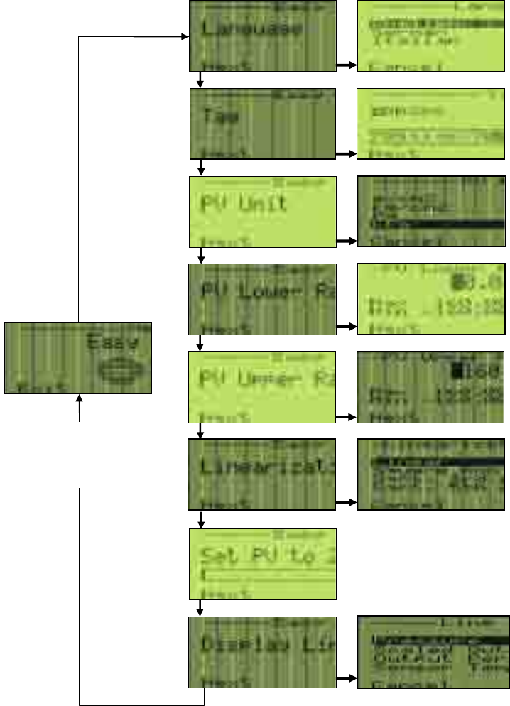
40 OI/266/WIHART-EN | 2600T Series Pressure transmitters
8 Operation
8.8.1 Easy Set-up
Press key (4) and select the language. After
entering the settings, press key (1) to move to
the next menu item.
Once in the alphabetic menu use Next (1) key
to position the cursor on the character that
you want to change. Scroll the character list
with (2) + (3), once on the selected one press
“next” key (1) once completed press “ok” (4).
Press the (4) key Scroll the eng. units list with
(2) + (3) and select with (4) key. Press the (1)
key to move to the next menu item.
Press the (4) key and set LRV value.
After entering the settings, press the (1) key
to move to the next menu item.
Press the (4) key and set LRV value.
After entering the settings, press the (1) key
to move to the next menu item.
Press the (4) key and select the transfer
function from the list with (2) + (3).
After entering the settings, press the “ok” (1)
key to move to the next menu item.
This function set to zero the PV value. Simply
press “ok” (4) key to activate the PV to zero
function. Press Next (1) key to move to the
next menu item.
This function allows the selection of the LCD
visualization. Select between the list and
confirm with “ok” (1) key.
In the configuration level, use the (2)
+ (3) keys to scroll to the “Easy Set-
up” menu item and select it by
pressing the (4) key.
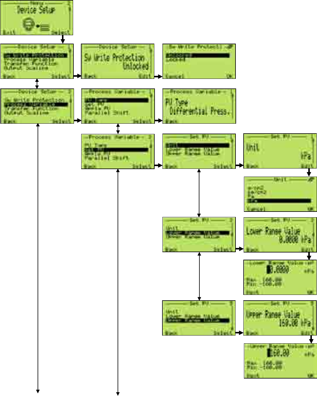
2600T Series Pressure transmitters | OI/266/WIHART-EN 41
8 Operation
8.8.2 Device Set-up
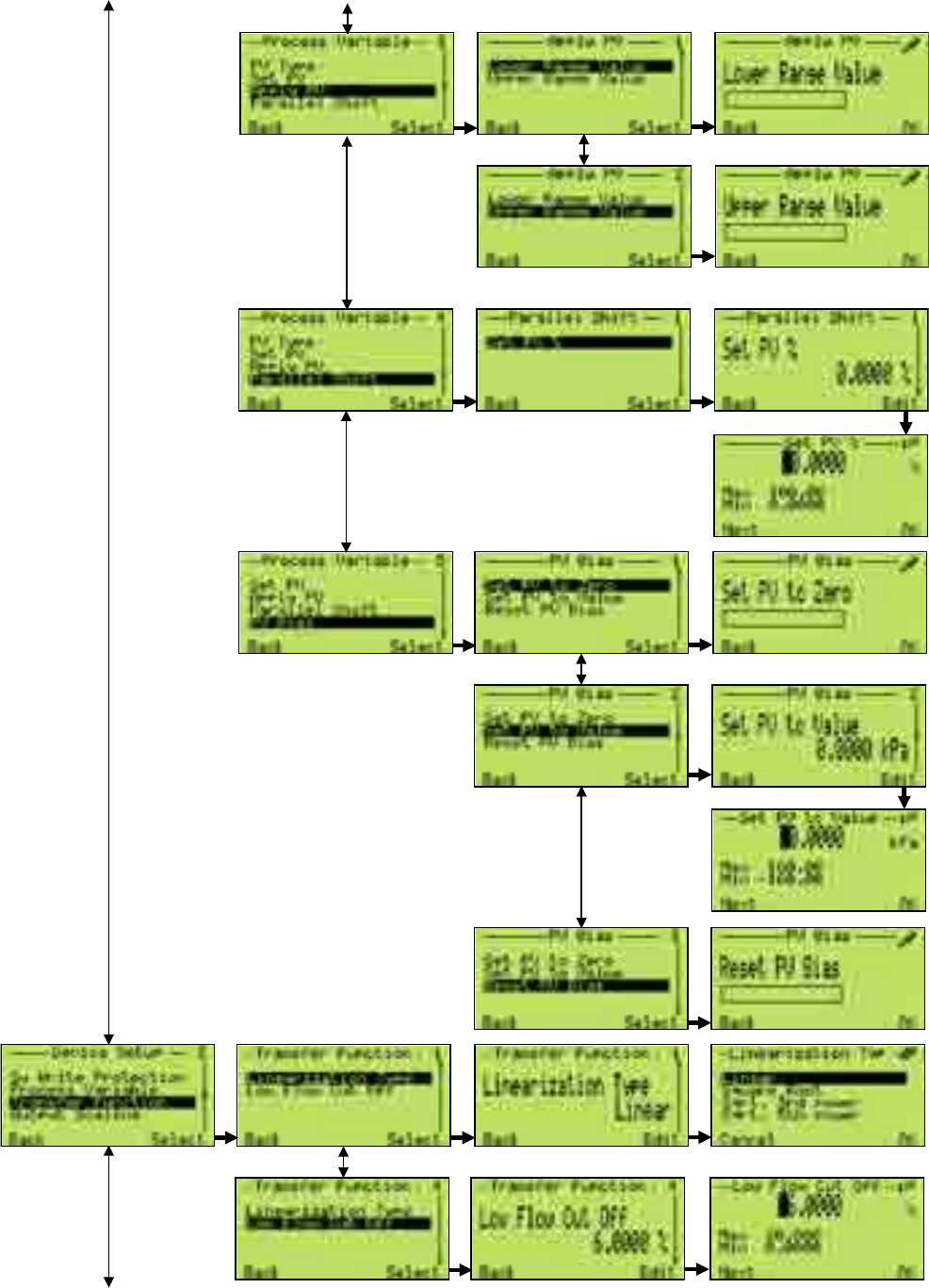
42 OI/266/WIHART-EN | 2600T Series Pressure transmitters
8 Operation
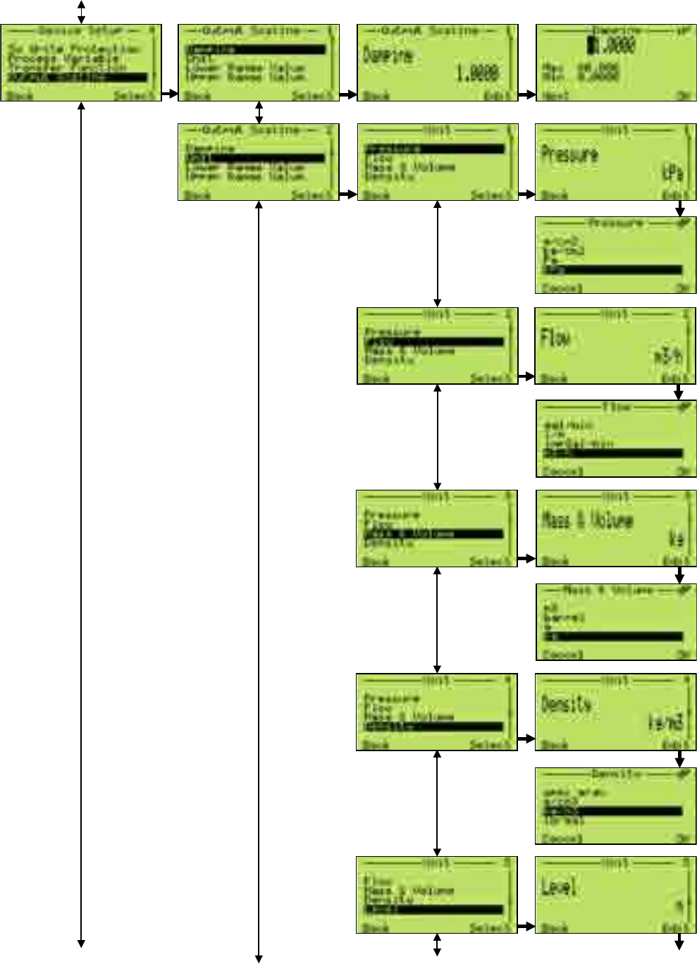
2600T Series Pressure transmitters | OI/266/WIHART-EN 43
8 Operation
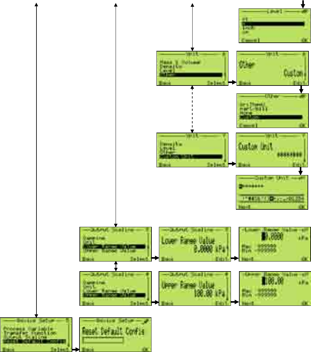
44 OI/266/WIHART-EN | 2600T Series Pressure transmitters
8 Operation
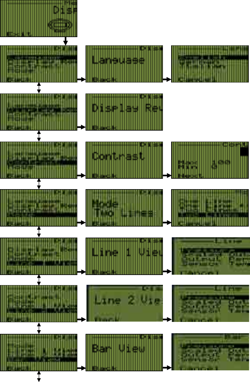
2600T Series Pressure transmitters | OI/266/WIHART-EN 45
8 Operation
8.8.3 Display
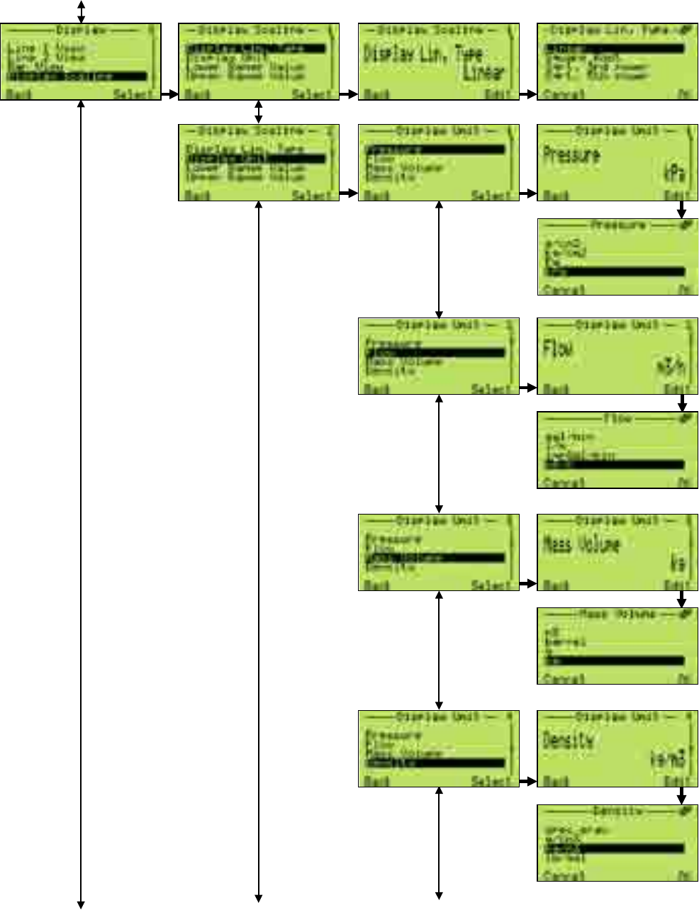
46 OI/266/WIHART-EN | 2600T Series Pressure transmitters
8 Operation
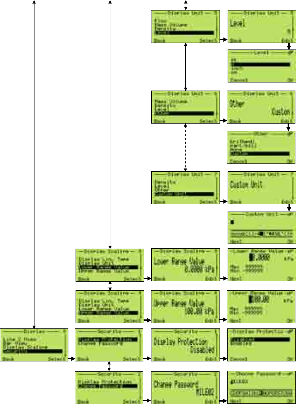
2600T Series Pressure transmitters | OI/266/WIHART-EN 47
8 Operation
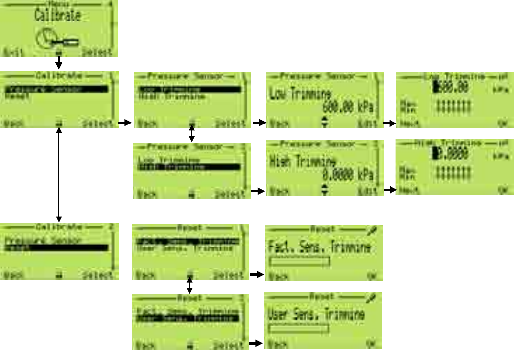
48 OI/266/WIHART-EN | 2600T Series Pressure transmitters
8 Operation
8.8.4 Calibrate
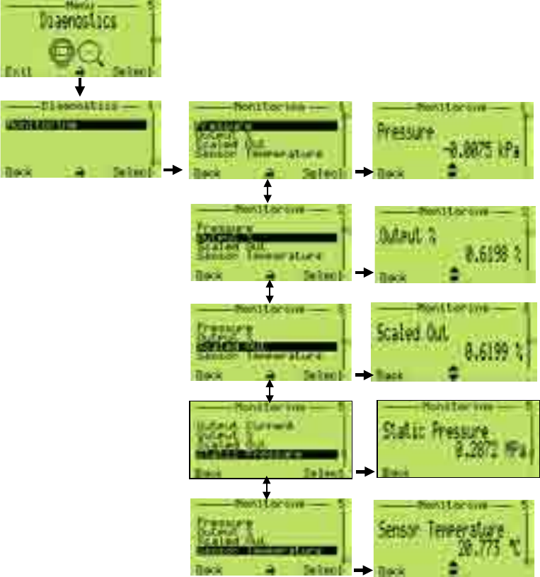
2600T Series Pressure transmitters | OI/266/WIHART-EN 49
8 Operation
8.8.5 Diagnostics
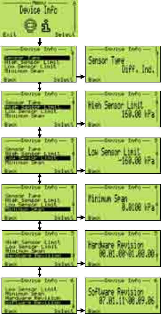
50 OI/266/WIHART-EN | 2600T Series Pressure transmitters
8 Operation
8.8.6 Device Info

2600T Series Pressure transmitters | OI/266/WIHART-EN 51
8 Operation
8.8.7 Communication
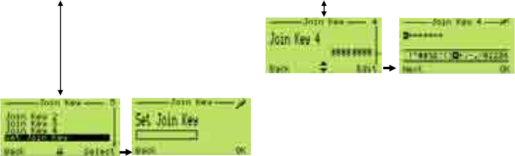
52 OI/266/WIHART-EN | 2600T Series Pressure transmitters
8 Operation
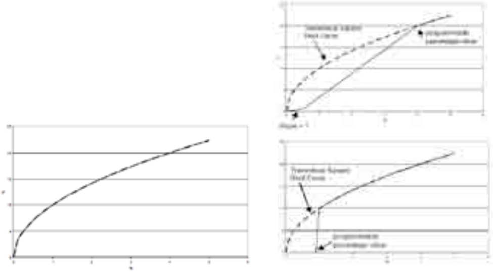
2600T Series Pressure transmitters | OI/266/WIHART-EN 53
8 Operation
8.9 Transfer function
The 266 Pressure Transmitter provides a selection of output
functions, as follows:
— Linear for differential, gauge and absolute pressure or level
measurements
— Sq. Root (x) for flow measurements using restriction type
primary element, like orifice plate, integral orifice, Venturi or
Dall tube and similar.
— Sq. Root (x3) for open channel flow measurements using
rectangular or trapezoidal weir
— Sq. Root (x5) for open channel flow measurements using
V-notch (triangular) weir.
— Bidirectional Flow
— Custom linearization table
— Cylindrical lying tank
— Spherical tank
These output functions can be activated using a Configuration
Tool (Digital LCD Integral Display, Hand Held Communicator or
PC based software as Asset Vision Basic).
8.12.1 Linear
Using this function, the relationship between the input
(measured value), expressed in % of the calibrated span and
the output is linear (i.e.: at 0% input, corresponds 0% output).
No further settings are possible here.
Figure 38: Linear output
8.9.2 Square root
Using the Square Root function, the output (in % of the span) is
proportional to the square root of the input signal in percentage
of the calibrated span.
The possibility to have the full Square Root function is given.
To avoid the extremely high gain error with the input approaching
zero, the transmitter output is linear with the input up with a
slope of 1 up to 0.5% and then still linear with the appropriated
slope to a programmable percentage value between 10 % and
20%. This option is offer in order to ensure a more stable output
when the signal is close to zero avoiding errors due to the high
gain of the square root.
To neglect the values with the input approaching zero, the
transmitter output is zero with the input up to a programmable
percentage value between 0 % and 20%. This option is offer in
order to ensure a more stable flow measure. This option is
possible for all the listed output functions. ).
Figure 39: Square-Root transfer functions
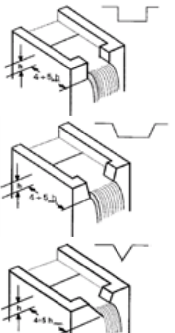
54 OI/266/WIHART-EN | 2600T Series Pressure transmitters
8 Operation
Figure 40: Tanks (respectively rectangula weir, trapezoidal weir and
V-notch weir)
8.9.4 Square root to the 5th power
The x5 Square root Transfer function can be used for open
channel flow measurement using ISO 1438 Vnotch (triangular)
weirs (see figure on the right) where the relationship between
the flow and the developed head h (the differential pressure
measured by the transmitter) is proportional to h5/2 or square
root of h5.
Using this function, the output (in % of the span) is proportional
to the square root of the fifth power of the input signal in % of
the calibrated span: the instrument (it gives an output
proportional to the rate of flow calculated using the Kingsvater-
Shen formula).
8.9.3 Square root to the 3rd power
The x3 Square root Transfer function can be used for open
channel (see figures on the right) flow measurement using ISO
1438 rectangular weirs (Hamilton Smith, Kindsvater-Carter,
Rehbock formulas) or trapezoidal weirs (Cippoletti formulas) and
ISO 1438 Venturi flumes. In these types of devices the relationship
between the flow and the developed head h (the differential
pressure measured by the transmitter) is proportional to h3/2 or
square root of h3.
Other types of Venturi or Parshall flume do not follow this
relationship. Using this function, the output is proportional to the
square root of the third power of the input signal in % of the
calibrated span: the instrument gives an output proportional to the
rate of flow calculated using the above mentioned formulas.
8.9.5 Custom linearization curve
The custom linearization curve transfer function it is used
typically for volumetric level measurement in tanks with an
irregular shape. It can be registered to a freely identifiable
transfer function with a maximum of 22 base points. The first
point is always the zero point, the last is always the final value.
Neither of these points can be altered.
A maximum of 20 points can be freely entered in between.
These points have to be defined by extrapolating the tank filling
table data and reducing them to 22 points.Once identified the
22 points they will need to be uploaded into the device by
either using an HART hand held terminal or a proper
configuration software like Asset Vision Basic.
8.9.6 Bidirectional Flow (to be used when the transmitter
is connected to a bidirectional flow element)
The bidirectional function, applied to the transmitter input (x)
expressed in percentage of the calibrated span, has the
following form:
Output = ½ + ½ sign (x) ∙ x ½
where “x” and “Output” should be normalized in the range 0 to
1 for calculation purpose, with the following Output meaning:
— Output = 0
— Output = 1
This function can be used for flow measurement purpose when
the flow is in both the directions and the primary elements are
designed to perform this type of measure.
As an example, if we have a bidirectional flow measurement
application with the following data:
Max reverse flow rate: -100 l/h
Max flow rate: +100 l/h
The differential pressure generated by the flow primary is for the
maximum flow rate 2500 mmH2O, for the max reverse flow rate
2500 mmH2O.
The transmitter will have to be configured as follows:
Calibrated span: LRV = -2500mmH2O
URV = +2500mmH2O
Transfer function: Bidirectional flow
2600T Series Pressure transmitters | OI/266/WIHART-EN 55
8 Operation
8.9.7 Cylindric lying tank
This function is used to measure the volumetric level into a
cylindrical horizontal tank with flat ends.
The transmitter calculates the volume from the measured filling
level.
8.9.8 Spherical Tank
This function is used to measure the volumetric level into a
spherical tank.
The transmitter calculates the volume from the measured filling
level.
8.10 Configuration with the PC/laptop or handheld
terminal
A graphical user interface (DTM) is required for configuration of
the transmitter via PC or laptop. For operating instructions,
please refer to the software description.
The 266 transmitters can be configured by either one of the
following device.
— Hand Held terminals like the ABB DHH805, Emerson
Process 375 and 475 provided the 266 EDD has been
downloaded and enabled in the terminal.
— ABB Asset Vision Basic, a new free of charge software
configurator downloadable at www.abb.com/
Instrumentation
— Any DTM based software for HART instruments
configuration provided it is compatible with EDD or DTM.
You can use a handheld terminal to read out or configure/
calibrate the transmitter.
For additional information, refer to the operating instructions
included with the handheld terminal.
If the transmitter has been configured in the factory according
to customer specifications for the measuring point, all you have
to do is mount the transmitter as prescribed (to correct
potential zero shifts, refer to the section “Correcting the zero
shift”), and switch it on. The measuring point will now be ready
for use.
If, however, you wish to make changes to the configuration, a
handheld terminal or - preferably - a graphical user interface
(DTM) is required. This DTM tool renders the device fully
configurable. It supports the HART protocol and and can be
run on a PC or laptop, or as part of an automation system.
Refer to the installation manual provided with the software for
the steps required to install the operating tool. The most
important parameters can be set via the path “Parametrize_
Differential Pressure Measurement”.
The program offers the option of configuring, polling, and
testing the transmitter.
In addition, offline configuration can be performed by means of
an internal database.
Each configuration step is subject to a plausibility check. You
can call up context-sensitive help at any time by pressing the
“F1” key. Immediately after you have received the transmitter or
before you change the configuration, we recommend that you
save the existing configuration data to a separate data storage
medium, via the path “File_Save”.
8.11 Configuration with the graphical user interface
(DTM) - System requirements
— Operating control program (e.g., ABB Asset Vision Basic
version 1.00.17 or higher)
— DTM (Device Type Manager; graphical user interface)
— Operating system (depending on the respective control
program)
To operate the Asset Vision Basic please refer to the relevant
operating instruction.
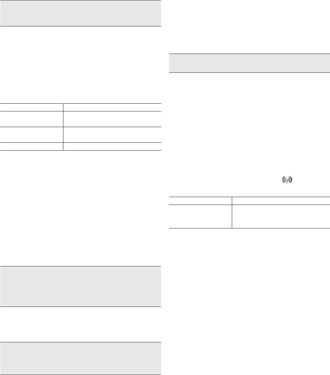
56 OI/266/WIHART-EN | 2600T Series Pressure transmitters
9 Troubleshooting
9 Troubleshooting
9.1 Overview
This section provides troubleshooting suggestions for the most
common problems occuring in the field.
Important.
Procedures described in the following paragraphs
will help the user to verify that 266 pressure transmitter and
wireless communication network are correctly in place.
9.2 Device-related issues
9.2.1 Device does not power on
When the user receives a 266 WirelessHART pressure
transmitter, the first step to be taken is to power the device on.
After removing the battery pull-tab grabbing it firmly and pulling
the cell will give power supply to the electronic module LCD
display will go live for 30 seconds and then it will go off.
If this doesn’t happen the possible cause could be:
Possible cause Solution
Battery discharged Change the battery (spare part number
DR3051)
Display or battery not well
connected
Check HMI contacts or invert battery position
into the terminal block
Terminal block defect Check battery and terminal blocks contacts
In case the device is not powering, please check if the battery
is still in good conditions and it has not been exposed to high
temperatures for long periods of time. To install a new battery,
please follow below instructions
1. Install 266 WirelessHART pressure transmitter properly,
according to ABB practices explained in the present
document using an approved thread sealant on all
connections.
2. Unscrew the battery cover from the wireless device.
Battery lays on the opposite side of the display (if installed)
as indicated by the writing “Field Terminals” engraved on
housing neck.
3. Remove and replace the battery paying attention to the
polarity.
Note. Wireless devices should be powered up only during the
network setup and beginning with the closest device to the
Gateway. This will result in a simpler and faster network installation.
For further information about the battery, please refer to paragraph
6.6 of this document.
4. Close the housing cover so as to have a metal-to-metal
contact but do not over tighten. If the installation of the
battery as been properly performed, the LCD display will
go live for 30 seconds and then it will go off.
Important. Battery part number is DR3051. To get spares batteries,
please get in touch with your local ABB service reference.
Replacements with non-ABB batteries is forbidden and will lead to
certification invalidity.
9.3 Network-related issues
9.3.1 General
Network joining could represent a critical point for a wireless
transmitter.
Basic preliminary setting for joining consists in writing two
parameters both into the device and into the Gateway. These
parameters are:
— Network ID
— Join Key
Important.
Network ID and Join Key are to be always the
same both on field instrument and Gateway.
It is also necessary to write the LONG TAG for communication
via Ethernet TCP/IP within the Asset Vision Basic projects.
The above-mentioned parameters can be set using:
— Asset Vision Basic wired to device dedicated terminals
through a HART modem.
— Hand-held terminal wired to device dedicated terminals
— Local HMI menu
9.3.2 Device does not join the network
After the basic settings have been correctly executed, a typical
anomalous situation is that the device does not join to the
wireless network.
Network is joined when the radio signal icon is steady
visible on the upper right-hand corner of the HMI (if installed).
Possible cause Solution
Power supply is missing
Access the “Z” button and depress it for few
seconds until the display goes live. If this will
not happen, see section 9.2.1
Anyway, device will more likely not join the network due to a
radio signal failure. Radio failure can be identified thanks to the
above-mentioned icon.

2600T Series Pressure transmitters | OI/266/WIHART-EN 57
9 Troubleshooting
Icon appearance Cuase and suggested actions
Icon is not visible
Serious radio failure
Check if there is a Radio Failure diagnostic
“ON”:
— using HART wired connection in
combination with Asset Vision Basic /
DTM
— access diagnostics using an Hand-held
Terminal
— visualize the internal diagnosis menu of
HMI by depressing the navigation
button on the bottom left-hand corner.
Icon is blinking
The device is trying to join and/or the joining
process is in progress. Normally the joining
process takes some time (up to 30 minutes).
If the icon keeps on blinking after this period
of time, please check if:
— Network ID and Join Key are properly
set.
— Long TAG is unique and different from
the network one.
— Wireless device has previously joined
the network with another Long TAG.
— Power cycle the pressure transmitter
and re-try.
— Verify whether the Network Manager is
in “advertise” mode
9.3.3 Burst troubleshooting
Burst communication mode allows a single slave pressure
transmiiter to continuously broadcast a standard HART reply
message at a certain, defined, configured interval. Details
about all possible with relating descriptions and corrective
actions will be reported in the following table.
X Y Description
O O Both services are OFF
N O Triggered service is OFF
A O Main service is active. Triggered service is OFF
S O Main service is shutting down. Triggered service is OFF
R O
Main service has been rejected. Triggered service is OFF
Possible causes and suggested actions:
— Timeout. Wait some minutes and retry
— Network Manager (gateway) stopped this operation due
to a conflict with another operation in progress. Wait
some minutes and retry.
— Network Manager (gateway) stopped this operation due
to unavailable bandwidth. Wait some minutes and retry
and/or slow down burst frequency to reduce band
allocation.
O N NOT ALLOWED
N N Both services under negotiation.
A N Main service active. Triggered service under negotiation.
S N NOT ALLOWED
R N
Main service has been rejected. Triggered service is under
negotiation. Burst is not active.
When the triggered service ends (regardless from the
outcome), it is necessary to wait some minutes and re-try. If
nothing changes, please slow down the update rate of the
rejected service.
O A NOT ALLOWED
N A NOT ALLOWED
A A Both services are active
S A NOT ALLOWED
R A
Main service has been rejected. Triggered service is active.
Burst is not active.
When the triggered service ends (regardless from the
outcome), it is necessary to wait some minutes and re-try. If
nothing changes, please slow down the update rate of the
rejected service.
O S Main service is OFF. Triggered service is shutting down.
N S Main service under negatiation. Triggered service is shutting
down
A S Main service is active. Triggered service is shutting down.
S S Both services are shutting down.
R S NOT ALLOWED
O R NOT ALLOWED
N R NOT ALLOWED
A R
Main service is active. Triggered service rejected. Burst is not
active.
When the triggered service ends (regardless from the
outcome), it is necessary to wait some minutes and re-try. If
nothing changes, please slow down the update rate of the
rejected service.
S R NOT ALLOWED
R R
Both services have been rejected. Burst is not active.
When the triggered service ends (regardless from the
outcome), it is necessary to wait some minutes and re-try. If
nothing changes, please slow down the update rate of the
rejected service.
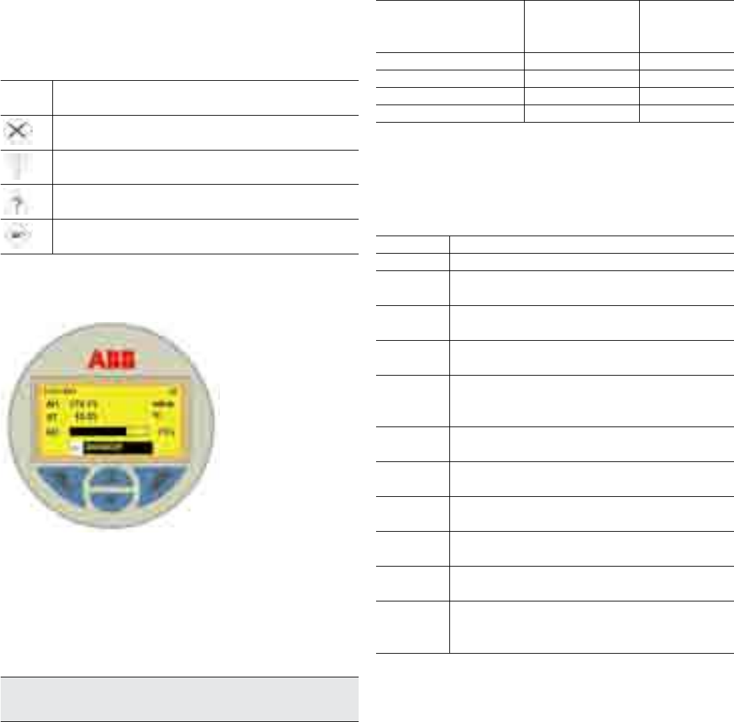
58 OI/266/WIHART-EN | 2600T Series Pressure transmitters
9 Troubleshooting
9.4 HMI as diagnostic indicator
While the HMI works as Variable Indicator, also diagnostic
strings can be displayed. Whenever a failure or warning
condition is detected within the transmitter, a message appears
in the low side of the display below the bar-graph. The
message is formed by the NAMUR NE107 icon and the string
of the component where the problem occurred.
NAMUR
icons Description
Error / Failure
Functional check (e.g. during simulation )
Out of Spec (e.g. Sensor temperature outside the specs limits)
Maintenance required
Figure 42: Example of “Maintenance / Sensor” and “Failure /
Electronics” diagnostic
Detailed diagnostic info from HMI
When the above kind of diagnostic information is displayed,
from the HMI it is also possible to see the details.
1. Press the center navigation keys for 4 seconds until two
special icons appear on the bottom corners of the display
Important. This step is necessary only for the keypad activation of
TTG HMI type. For conventional HMI start from step 2.
2. Press the left navigation key
3. The HMI enter in the special menu with three items:
Diagnostics
Operator View 1
Signals View
4. Select “Diagnostics” and the list of all the active error
conditions appears with on top the worst condition.
The format of how the detailed diagnostic info are displayed is
“XA.BBB” where:
X = NAMUR NE107
Categories
A = Priority.
(Higher number =
higher priority)
BBB = error
code
F = Failure
M = Maintenance
O = Out of Specification
C = Function Check
9.5 HMI as feedback of the local push button
operations
As consequence of the operations described in the section 8.2,
when the Z or S buttons are released, the feedback of the
executed operation is displayed in the bottom of the LCD
(same position as per diagnostic messages):
Message Description
! Oper Done The push button operation has been successfully executed
! Proc Too
Low
The Pressure measured in input is too low and not
acceptable for the requested operation
! Proc Too
High
The Pressure measured in input is too high and not
acceptable for the requested operation
! New URV
Error
The Zero (Z) operation cannot be accepted because the
URV would be shifted outside the Upper Sensor limit
! Span Error
The Span (S) operation cannot be accepted because the
new URV would be too close to the LRV and their
difference lower than the Minimum Span value
! Oper
Disabled
The push button operation has been refused because the
Write Protection is enabled.
! LRV Too
Low
New LRV is too low and not acceptable for the requested
operation
LRV Too
High
New LRV is high low and not acceptable for the requested
operation
URV Too
Low
New URV is too low and not acceptable for the requested
operation
URV Too
High
New URV is high low and not acceptable for the requested
operation
Armed
Device is armed to accept HART command 73 “Find
Device”. This message can be triggered only during the
device wakeup operation
Possible sources of error are: ELECTRONICS, SENSOR,
PROCESS and CONFIGURATION. These sources can show up
the above listed icons according to the specific case.

2600T Series Pressure transmitters | OI/266/WIHART-EN 59
9 Troubleshooting
9.6 Error states and alarms
— Communication Board / Electronic related error messages.
Error message Tx LCD message Possible cause Suggested action
F240.023 Electronic Memory Failure Electronic memory corrupted The electronic must be replaced
M140.024 NV Electronic Memory Burn Error Writings to the electronic non-Volatile Memory
has not been successful
The communication board should be replaced as
soon as possible
M055.041 Electronic temperature out of limits
—Sensor related error messages
Error message Tx LCD message Possible cause Suggested action
F250.016 Sensor Invalid The sensor model/version is no longer compatible with the
connected electronic version The sensor must be replaced
F245.017 Sensor Memory Fail Sensor memory corrupted The sensor must be replaced
F225.000 P-dP Sensor Fail Mechanical damage to the sensor. Loss of fill fluid from the cell,
ruptured diaphragm, broken sensor. The sensor must be replaced
F220.001 Static Pressure Sensor Fail The circuitry for the sampling of the static pressure has failed. The sensor must be replaced
F215.002 Sensor Temperature Fail The circuitry for the sampling of the temperature has failed. The sensor must be replaced
M145.018 NV Sensor Memory Burn Error Writings to the sensor non-Volatile Memory was not successful The sensor should be replaced
as soon as possible.
—Installation/Start-up related error messages.
Error message Tx LCD message Possible cause Suggested action
C160.030 Input Simulation
Active
The P-dP Value produced in output is derived by the value
simulated in input
Use a HART configurator (DTM - Hand held) to place
device back in to normal operating mode (Remove
the input simulation)
C160.030 Input Simulation
Active
The Static Pressure Value produced in output is derived
by the value simulated in input
Use a HART configurator (DTM - Hand held) to place
device back in to normal operating mode (Remove
the input simulation)
C160.030 Input Simulation
Active
The Sensor Temperature Value produced in output is
derived by the value simulated in input
Use a HART configurator (DTM - Hand held) to place
device back in to normal operating mode (Remove
the input simulation)
C160.030 Input Simulation
Active
The Engineering Output Value is simulated to became the
measured Engineering Output value
Use a HART configurator (DTM - Hand held) to place
device back in to normal operating mode (Remove
the input simulation)
M050.042 Replace Info The Electronics or the Sensor have been changed but the
replacement operation has not been executed
The replacement operation must be executed: Move
the SW 1 of the electronics in position 1 = Enable
replace mode -Select the SW 2 the element that has
been changed between new Sensor or new
electronics -Power Cycle the device -Move the SW 1
of the electronics in position 0

60 OI/266/WIHART-EN | 2600T Series Pressure transmitters
9 Troubleshooting
— Process related error messages.
Error message Tx LCD message Possible cause Suggested action
F200.004 P-dP Out Of Limits
The measured Process Pressure value is outside the sensor
limits and no longer representing the true applied process
value.
The compatibility of pressure transmitter
model and process conditions has to be
checked. Probably a different transmitter
type is required.
F195.005 Static Pressure Out of Limits
The static pressure of the process exceeds the limit of the
sensor. Exceeding the Static Pressure can reduce accuracy,
mechanically damage the diaphragm and may require
calibration/replacement. An incorrect transducer model
could have been selected.
The compatibility of pressure transmitter
model and process conditions has to be
checked. Probably a different transmitter
type is required.
S190.006 Sensor Temperature Out of Limits
The temperature of the process environment affects the
pressure transmitter; Excess temperature can reduce
accuracy, degrade device components and may require
calibration/replacement.
The compatibility of pressure transmitter
model and process conditions has to be
checked. A different installation type could
be required e.g. use of remote seals.
M155.031 Max Working Pressure Exceeded
The static pressure of the process exceeds the max working
Pressure supported by the transmitter. Exceeding the Max
Working Pressure can mechanically damage the process
connections (flanges, pipes….) and/or be dangerous
The compatibility of pressure transmitter
model and process conditions has to be
checked.
S150.010 Primary variable out of range The measured pressure value is beyond its Low or High
scaling limits Adjust the working range if possible.
— Network/Wireless related error messages.
Error message Tx LCD message Possible cause Suggested action
F210.015 Radio Failure The communication between electronic and wireless chip is
not established. The electronics must be replaced
F205.014 Join Failure The connection to the wireless network is failed. Check the Network ID, Join Key and the Long Tag set
M185.011 Battery Warning Battery Life calculated value is under the specified threshold. The Battery must be replaced

2600T Series Pressure transmitters | OI/266/WIHART-EN 61
10 Maintenance
10 Maintenance
If transmitters are used as intended under normal operating
conditions, no maintenance is required. It is sufficient to check
the output signal at regular intervals (in accordance with the
operating conditions), as described in the instructions in the
section “Operation resp. Configuration of the transmitter”. If
deposits are expected to accumulate, the measuring
equipment should be cleaned on a regular basis, in accordance
with the operating conditions. Cleaning should ideally be
carried out in a workshop.
Repair and maintenance activities may only be performed by
authorized customer service personnel.
When replacing or repairing individual components, original
spare parts must be used.
Attention – Potential damage to parts. The electronic
components of the printed circuit board can be damaged by static
electricity (observe ESD guidelines). Make sure that the static
electricity in your body is discharged when touching electronic
components. If a remote seal is mounted on the measuring
equipment, it must not be removed (please refer to the dedicated
document).
Warning – <Bodily injury>. Transmitter for hazardous classified
location must be either repaired by the manufacturer or approved
by a certified expert following repair work Observe the relevant
safety precautions before, during and after repair work. Only
disassemble the transmitter to the extent necessary for cleaning,
inspection, repairs, and replacement of damaged components.
10.1 Returns and removal
Defective transmitters sent to the repairs department must,
wherever possible, be accompanied by your own description of
the fault and its underlying cause.
Warning – General risks. Before removing or disassembling the
device, check for hazardous process conditions such as pressure
on the device, high temperatures, aggressive or toxic media, and
so on. Read the instructions in the sections “Safety” and “Electrical
connection”, and perform the steps outlined there in reverse order.
10.2 Pressure transmitter sensor
Essentially maintenance is not required for the transmitter
sensor. Anyway the following items should be checked
periodically:
— Check the integrity of the pressure boundary (no cracks
should be visible on the process connection or on the
process flanges.
— Check that there is no leakage from the sensor/flange
interface or from the vent/drain valves.
— The process flanges bolts (for 266DSH) should not show
excessive rust.
In case one of the check points above fails, please replace the
damaged part with an original spare part.
Please contact your local ABB office for spare parts support
information or refer to the spare part list.
The use of non original spare parts makes the warranty void. In
case you want ABB to perform the repair, please send back the
transmitter to your local ABB office complete with the return
form that you find in this manual appendix and include it with
the device.
10.3 Removing/Installing the process flanges
1. Slacken the process flange screws by working on each in
a crosswise manner (hexagon head, SW 17 mm (0.67inch)
for 266DS.
2. Carefully remove the process flange, making sure that the
isolating diaphragms are not damaged in the process.
3. Use a soft brush and a suitable solvent to clean the
isolating diaphragms and - if necessary - the process
flange.
4. Insert the new process flange O-rings in the process
flange.
5. Attach the process flange to the measuring cell.
The surfaces of both process flanges must be at the same level
and at a right angle to the electronics housing (with the
exception of vertical process flanges).
6. Check that the process flange screw thread can move
freely: Manually turn the nut until it reaches the screw
head. If this is not possible, use new screws and nuts.
7. Lubricate the screw thread and seats of the screw
connection.
8. While performing the preliminary and final tightening of the
bolts, please act in a crosswise manner.
Attention – Potential damage to parts. Do not use sharp or
pointed tools.
Do not damage the insolating diaphragms.
Important. In the case of oil and grease-free designs, clean the
measuring chambers again if necessary once the process flange
has been installed.

62 OI/266/WIHART-EN | 2600T Series Pressure transmitters
10 Maintenance
— Respect the below table indications for reinstalling the process flanges.
Transmitter model and range Procedure
266DSH / PSH / VSH
Viton Gaskets All bolting Use a torque wrench to tighten the bolts to a torque of 25 Nm.
PTFE Gaskets
Carbon Steel NACE
and Stainless Steel
Use a torque wrench to tighten the process flange nuts to a torque of 40 Nm, let the flange
stabilize for an hour, unscrew the nuts and tighten again to 25 Nm.
Stainless Steel
NACE
Use a torque wrench to tighten the process flange nuts to a torque of 25 Nm, let the flange
stabilize for an hour and perform the final tightening to 25 Nm.
266DSH.x.H
(High static option)
Viton Gaskets All bolting Use a torque wrench to tighten the bolts to a torque of 31 Nm.
PTFE Gaskets All bolting Use a torque wrench to tighten the process flange nuts to a torque of 40 Nm, let the flange
stabilize for an hour, unscrew the nuts and tighten again to 31 Nm.
266DSH range A
(1KPa) All gaskets All bolting
Use a torque wrench to tighten the process flange screws/nuts to a torque of 14 Nm. Please be
aware that in case of bottom work disassembly and reassembly the original performances can not
be guarantee anymore.
266DSH with Kynar
inserts All gaskets All bolting Use a torque wrench to tighten the process flange screws/nuts to a torque of 15 Nm
10.4 Pressure transducer replacement
If the pressure transducer needs to be replaced proceed as
follows:
1. Insulate the transmitter from the process by acting on the
manifolds or on the insulation valves.
2. Open the vent valves to allow sensor depressurization.
3. Remove the battery.
4. Disconnect the transmitter from the bracket unscrewing the
fixing bolts.
5. Open the communication board compartment cover.
6. The communication board is connected to the sensor via a
flat cable and a connector. Remove the communication
board and gently disconnect the connector.
7. Release the tang screw until nd rotate the housing until its
complete removal.
8. Unscrew the fixing bolts from the transducer and remove
the process flanges.
9. The orings placed between the diaphragm and the flange
(Viton or PTFE) must be replaced after every disassembly.
10. Reassemble the flanges following the steps above in
reverse order.
11. The 266 can reconfigure itself with the previous configured
parameters thanks to the auto-configuration functionality.
12. Before powering on the transmitter raise dip-switches 1 and
2 in up position. Install the battery, wait ten seconds and
lower dip-switched 1 and 2 .
13. After installing the transmitter on the bracket and
connecting it to the manifold, performe a PV zero bias.
10.5 Electronic replacement
If the electronic module needs to be replaced proceed as follows:
1. Insulate the transmitter from the process by acting on the
manifolds or on the insulation valves.
2. Open the vent valves to allow sensor depressurization.
3. Remove the battery.
4. Open the communication board compartment cover and
remove the LCD display (if installed).
5. Remove the communication board and gently disconnect
the connector.
6. Connect the sensor flat cable to the new electronic module
with dip switch 1 in up position.
7. Connect the transmitter to power supply, wait ten seconds
and lower dip-switch 1 to 0 position. 266 can reconfigure
itself with the previous configured parameters thanks to the
auto-configuration functionality.
10.6 Battery replacement
1. Remove the housing cover of the “field terminals” side.
See the indication engraved on one side of the housing.
2. Remove the battery and pulling it completely outside from
its slot.
3. Replace the battery paying attention to the polarity and
assuring that the cell makes contact with the electronic
module.
Note.
266 WiPressure battery is manufactured by TADIRAN
Batteries GmbH (manufacturer code SL 2780)
4. Before installing the huosing cover, check whether the
display is working or not. If yes, put back the housing
cover, turn it to seat O-ring into the housing and then
continue to hand tighten until the cover contacts the
housing metal-to-metal. If display is not working, please
refer to the troubleshooting section.
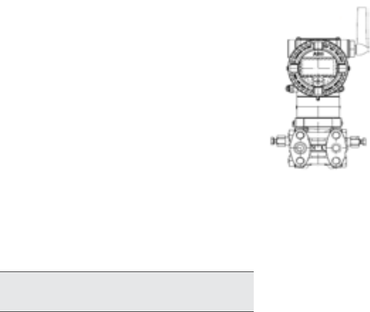
2600T Series Pressure transmitters | OI/266/WIHART-EN 63
11 Hazardous area considerations
11 Hazardous Area considerations
11.1 Ex Safety aspects and IP Protection (Europe)
According to ATEX Directive (European Directive 94/9/EC of 23
March 1994) and relative European Standards which can
assure compliance with Essential Safety Requirements, i.e.,
EN 60079-0 (General requirements) EN 60079-11 (Equipment
protection by intrinsic safety “i”) EN 60079-26 (Equipment with
equipment protection level -EPL- Ga) the pressure transmitters
of the 2600T SERIES wireless have been certified for the
following group, categories, media of dangerous atmosphere,
temperature classes, types of protection. Examples of
application are also shown below by simple sketches.
a) Certificate ATEX II 1 G Ex ia IIC T4
FM Approvals certificate number
FM14ATEX0007 (Lenno products)
The meaning of ATEX code is as follows:
— II : Group for surface areas (not mines)
— 1 : Category
— G : Gas (dangerous media)
Certificate IECEx Ex ia IIC T4, IP67
IECEx certificate number
IECEx FME 14.0002 (Lenno products only)
Important. The number close to the CE marking of the transmitter
safety label identifies the Notified Body which has responsibility for
the surveillance of the production.
The other marking refers to the protection type used according
to relevant EN standards:
— Ex ia: Intrinsic safety, protection level “a”
— IIC: Gas group
— T4: Temperature class of the transmitter
(corresponding to 135°C max) with a Ta from -50°C to +70°C
About the applications, this transmitter can be used in “Zone 0”
(Gas) classified areas (continuous hazard) as it is shown on the
following sketch.
Application with Gas
Zone 0
266 Tx Category 1G Ex ia
Application for pressure transmitter Ex ia categories 1G
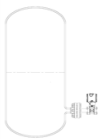
64 OI/266/WIHART-EN | 2600T Series Pressure transmitters
11 Hazardous area considerations
b) Certificate ATEX II 1/2 G Ex ia IIC T4
FM Approvals certificate number
FM14ATEX0007 (Lenno products)
The meaning of ATEX code is as follows:
— II: Group for surface areas (not mines)
— 1/2: Category - It means that only a part of the transmitter
complies with category 1 and a second part complies with
category 2 (see next application sketch).
— G: Gas (dangerous media)
Certificate IECEx Ex ia IIC T4, IP67
IECEx certificate number
IECEx FME 14.0002 (Lenno products only)
The other marking refers to the protection type used according
to relevant EN standards:
— Ex ia: Intrinsic safety, protection level “a”
— IIC: Gas group
— T4: Temperature class of the transmitter
(corresponding to 135°C max) with a Ta from -50°C to +70°C
About the applications, this transmitter can be used in Zone “0”
(Gas) classified areas (continuous hazard) with its “process
part” only, whereas the remaining part of the transmitter, i.e. its
enclosure, can be used in Zone 1 (Gas), only (see sketch
below). Reason of this is the process part of the transmitter
(normally called primary transducer) that provides inside
separation elements to seal off the electrical sensor from the
continuously hazardous process, according to the
EN 60079-26.
Application with Gas
Zone “0” Zone “1”
Dangerous
medium
(process)
Tank
Zone “0” / Zone “1”
separation element
Primary transducer
266 Tx
Category
1/2 G Ex ia
Application for pressure transmitter Ex ia categories 1/2G
IP code
About the degree of protection provided by the enclosure of
the pressure transmitter, the 2600T SERIES wireless has been
certified IP67 according to EN 60529 standard. The first
characteristic numeral indicates the protection of the inside
electronics against ingress of solid foreign objects including
dusts.
The assigned “6” means an enclosure dust-tight (no ingress of
dust).
The second characteristic numeral indicates the protection of
the inside electronics against ingress of water.
The assigned “7”means an enclosure water-protected against a
temporary immersion in water under standardized conditions of
pressure and time.
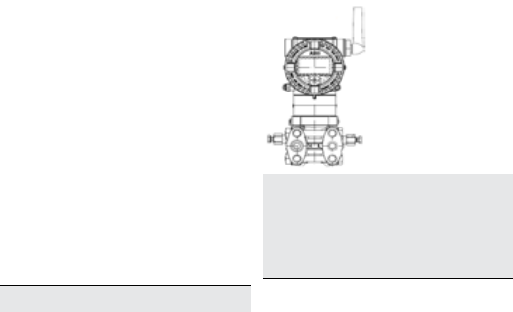
2600T Series Pressure transmitters | OI/266/WIHART-EN 65
11 Hazardous area considerations
According to ATEX Directive (European Directive 94/9/EC of 23
March 1994) and relative Standards which can assure compliance
with Essential Safety Requirements, i.e., EN 60079-0 (General
requirements) EN 60079-15 (Specification for electrical apparatus
with type of protection “n”), the pressure transmitters of the 2600T
SERIES wireless have been certified for the following group,
categories, media of dangerous atmosphere, temperature classes,
types of protection. Examples of application are also shown below
by simple sketches.
c) Certificate ATEX II 3 G Ex nA IIC T4
(for T4 = -50°C ≤ Ta ≤+70°C)
FM Approvals Certificate number
FM14ATEX0008 (Lenno products only)
The meaning of Atex code is as follows :
— II 3G Ex nA IIC T4 (for T4 = -50°C < Ta < +70°C)
— II: Group for surface areas (not mines)
— 3: Category of equipment
— G: Gas (Dangerous media)
— Ex nA type of protection “n” with “no sparkling” technique
— IIC: gas group
— T4: Temperature class of the transmitter (which
corresponds to 135°C max) with a Ta from -50°C to +70°C
Important. It is the technical support for the ABB Declaration of
Conformity
About the applications, this transmitter can be used in Zone 2
(Gas) (unlikely/infrequent hazard) as it shown on the following
skecth.
Certificate IECEx Ex nA IIC T4
IECEx certificate number
IECEx FME 14.0002 (Lenno products only)
The meaning of IECEx code is as follows :
— Ex nA type of protection “n” with “no sparkling” technique
— IIC: gas group
— T4: Temperature class of the transmitter (which
corresponds to 135°C max) with a Ta from -50°C to +70°C
Application with Gas
Zone 2
266 Tx Category 3G Ex nA
Important - Note for pressure transmitter with combined
approval. Before installation of the Transmitter, the customer
should permanent mark his chosen Protection Concept on the
safety label. The transmitter can only be used with according to this
Protection Concept for the whole life. If two or more types of
protection box (on safety label) are permanent marked, the pressure
transmitter must be removed from hazardous classified locations.
The selected Type of Protection is allowed to be changed only by
manufacturer after a new satisfactory assessment.
Application for pressure transmitter Ex nA categories 3G
66 OI/266/WIHART-EN | 2600T Series Pressure transmitters
11 Hazardous area considerations
11.2 Ex Safety aspects and IP Protection
(North America)
11.2.1 Applicable standards
According to FM Approvals Standards which can assure
compliance with Essential Safety Requirements
FM 3600: Electrical Equipment for use in Hazardous
(Classified) Locations, General Requirements.
FM 3610: Intrinsically Safe Apparatus and Associated
Apparatus for Use in Class I, II, III, Division 1,
and Class I, Zone 0 & 1 Hazardous (Classified)
Locations.
FM 3810: Electrical and Electronic Test, Measuring and
Process Control Equipment.
11.2.2 Classifications
The 2600T SERIES wireless pressure transmitters have been
certified by FM Approvals for the following Class, Divisions and
Gas groups, hazardous classified locations, temperature class
and types of protection.
— Intrinsically Safe for use in Class I, II and III, Division 1,
Groups A, B, C, D.
— Temperature class T4
— Ambient Temperature range -50°C to +70°C (dependent
on the maximum input current and the maximum
temperature class).
— Electrical Supply 3.6 V by “D” size cell.
— Type 4X applications Indoors/Outdoors.
For a correct installation in field of 2600T SERIES wireless
pressure transmitters please see the related control drawing.

2600T Series Pressure transmitters | OI/266/WIHART-EN 67
12 Regulatory Compliance for Radio and Telecommunication
12 Regulatory Compliance for Radio and Telecommunication
All wireless devices require certification to ensure that they adhere to regulations regarding the use of the RF spectrum. Nearly
every country requires this type of product certification. ABB is working with governmental agencies around the world to supply
fully compliant products and remove the risk of violating country directives or laws governing wireless device usage.
12.1 FCC Compliance
This equipment Contains FCC ID: 2AC5O-WICB.
This device complies with Part 15 of the FCC Rules. Operation is subject to the following conditions: This device may not cause
harmful interference this device and must accept any interference received, including interference that may cause undesired
operation.
Warning. Changes or modifications not expressely approved by the party responsible for compliance could void the user’s authority to
operate the equipment.
Warning. When using this product, it should be installed and operated with a minimum distance of 20 cm between the radiator and your
body. This transmitter must not be collocated or operate in conjunction with any other antenna or transmitter.
12.2 IC Compliance
This equipment Contains IC: 12311A-WICB.
This Class A digital apparatus complies with Canadian ICES-003.
This device complies with Industry Canada license-exempt RSS standard(s). Operation is subject to the following two conditions:
(1) this device may not cause interference, and (2) this device must accept any interference, including interference that may cause
undesired, operation of the device.
Le présent appareil est conforme aux CNR d’Industrie Canada applicables aux appareils radio RSS-210. L’exploitation est
autorisée aux deux conditions suivantes : (1) l’appareil ne doit pas produire de brouillage, et (2) l’utilisateur de l’appareil doit
accepter tout brouillage radioélectrique subi, même si le brouillage est susceptible d’en compromettre le fonctionnement.
Under Industry Canada regulations, this radio transmitter may only operate using an antenna of a type and maximum (or lesser)
gain approved for the transmitter by Industry Canada. To reduce potential radio interference to other users, the antenna type and
its gain should be so chosen that the equivalent isotropically radiated power (e.i.r.p.) is not more than that necessary for
successful communication.
12.3 R&TTE Compliance 1999/5/EC
266 WirelessHART pressure transmitters are in compliance with Radio and Telecommunications Terminal Equipment Directive (R&TTE)

68 OI/266/WIHART-EN | 2600T Series Pressure transmitters
ABB
TROUBLE SHEET
WARRANTY REPAIR REPAIR ORDER
Rejection or discrepancy Reports copy attached not available
IDENTIFICATION
Customer
Purchase order No
Plant
Name of person to contact
Instrument Tag No
Model
Serial Number
OPERATING CONDITIONS
Specify location, environmental conditions, type of service and approximate number of operating hours or
date of installation if known
REASON FOR RETURN
DANGEROUS FLUIDS
In case of toxic or otherwise dangerous fluid, please attach the relevant Material Safety Data Sheet
Trouble found during. Installation
Commissioning Maintenance
At start up On service
Shipping information for the return of the equipment
M
ate
ri
a
l r
etu
rn
ed
f
o
r f
acto
r
y
r
epa
ir
s
h
ou
l
dbe se
n
tto t
h
e
n
ea
r
est
ABB
Se
rvi
ce Ce
n
te
r
; t
r
a
n
spo
r
tat
i
o
n
c
h
a
r
ges p
r
epa
i
dby t
h
e
P
u
r
c
h
aser
Please enclose this sheet duty completed to cover letter and packing list
Date Signature Originator
ABB S.p.A
Process Automation Division
Sales Office: Via Statale, 113 - 22016 Lenno (CO) Italy
Tel. +39 0344 58 111
Fax +39 0344 56 278
e-mail: abb.instrumentation@it.abb.com

2600T Series Pressure transmitters | OI/266/WIHART-EN 69
RETURN REPORT – No.: _ _ _ _ _ _ _ _
*) Please always fill in. Otherwise the case will not be handled as return
ABB
CONTROL OF SUBSTANCES HAZARDOUS TO HEALTH (C.O.S.H.H.)
Decontamination declaration - EQUIPMENT RETURNED FOR REPAIR, CALIBRATION OR CREDIT
From
Description
Return authorization no.
Model number
Serial number
A) The above equipment has not been in contact with any material which is hazardous to health.
B) The above equipment has been in contact with the material(s) noted below but that it has now been
completely de-contaminated and is now safe to handle and dismantle without any special precautions.
Material(s) which have been in contact with this equipment:
C) If A) or B) are not applicable full instructions for the safe handling of this equipment for disposal must be
supplied.
Please delete A), B) or C) above as applicable, complete the signature section below, then send the completed
declaration either with the returned items, or by fax for the attention of the Calibration & Repair Centre..
Note – no action to examine or repair equipment will be undertaken until a valid COSHH declaration has been
received, completed by an authorized officer of the end user company.
Signed
Name
Position
Date
ABB S.p.A
Process Automation Division
Uffici Commerciali / Sales Office:
Via Statale, 113 - 22016 Lenno (CO) Italy
Tel. +39 0344 58 111
Fax +39 0344 56 278
e-mail: abb.instrumentation@it.abb.com

70 OI/266/WIHART-EN | 2600T Series Pressure transmitters
Products and customer support
ABB’s portfolio for valve automation:
− Continuous electrical actuators and pneumatic actuators
− Electro-pneumatic, pneumatic, and digital positioners
− I/P signal converters
ABB’s pressure measurement:
− Absolute, gauge and differential pressure transmitters
− IEC 61508 SIL2/3 certified pressure transmitters and switches
− Multivariable transmitters
− Interface level/density transmitters
− Pressure measurement remote seals
− Pressure measurement accessories
− Pneumatic pressure transmitters
ABB’s temperature measurement:
− Universal temperature sensors
− High-temperature sensors
− Temperature sensors for sanitary applications
− Mineral isolated temperature sensors
− Thermowells
− Temperature transmitters
− IEC 61508 SIL2/3 certified temperature sensors and
transmitters
ABB’s portfolio of recorders and controllers:
− Process controllers and indicators
− Videographic recorders
− Paper chart recorders
− Field mountable indicators and controllers
ABB’s portfolio of level measurement:
− Magnetic level gauges
− Magnetostrictive and guided wave radar level transmitters
− Laser and scanner level transmitters
− Ultrasonic, capacitance and vibrating fork level transmitters
and switches
− Rotating paddle and thermal dispersion level switches
− IEC 61508 SIL2/3 certified level transmitters
ABB’s portfolio of device management:
− Fieldbus and wireless solutions
− Scalable asset & device management
− Asset vision software
− Mobility handhelds
Customer support
We provide a comprehensive after sales service via a
Worldwide Service Organization.
Contact one of the following offices for details on your nearest
Service and Repair Centre.
ABB S.p.A.
Via Statale 113,
22016 Lenno (Co) – Italy
Tel: +39 0344 58111
Fax: +39 0344 56278
ABB Automation Product GmbH
Schillerstrasse 72
D-32425 Minden – Germany
Tel: +49 551 905534
Fax: +49 551 905555
ABB Inc.
125 E. County Line Road
Warminster, PA 18974 – USA
Tel: +1 215 6746000
Fax: +1 215 6747183
ABB Inc.
3450 Harvester Road
Burlington, Ontario L7N 3W5 – Canada
Tel: +1 905 6810565
Fax: +1 905 6812810
ABB India Ltd.
Peenya Industrial Area, Peenya
Bangalore, Karnataka 560058 – India
Tel: +91 80 4206 9950
Fax: +91 80 2294 9389
ABB Engineering (Shanghai) Ltd.
No.5, Lane 369, Chuangye Rd., Pudong District,
Shanghai 201319 - P.R. China
Tel: +86 21 6105 6666
Fax +86 21 6105 6677
Client Warranty
Prior to installation, the equipment referred to in this manual
must be stored in a clean, dry environment, in accordance
with the Company‘s published specification. Periodic checks
must be made on the equipment‘s condition. In the event of a
failure under warranty, the following documentation must be
provided as substantiation:
— A listing evidencing process operation and alarm logs
at time of failure.
— Copies of all storage, installation, operating and
maintenance records relating to the alleged faulty unit.
2600T Series Pressure transmitters | OI/266/WIHART-EN 71
Intentionally blank

OI/266/WIHART-EN 03.2014
ABB Ltd.
Process Automation
Howard Road, St. Neots
Cambridgeshire, PE19 8EU
UK
Tel: +44 (0)1480 475321
Fax: +44 (0)1480 217948
ABB Inc.
Process Automation
125 E. County Line Road
Warminster, PA 18974
USA
Tel: +1 215 674 6000
Fax: +1 215 674 7183
ABB Automation Product GmbH
Schillerstrasse 72
D-32425 Minden
Germany
Tel: +49 551 905534
Fax: +49 551 905555
ABB S.p.A.
Process Automation
Via Statale 113
22016 Lenno (CO),
Italy
Tel: +39 0344 58111
Fax: +39 0344 56278
www.abb.com
Contact us
Note
We reserve the right to make technical changes or
modify the contents of this document without prior
notice. With regard to purchase orders, the agreed
particulars shall prevail. ABB does not accept any
responsibility whatsoever for potential errors or
possible lack of information in this document.
We reserve all rights in this document and in the
subject matter and illustrations contained therein.
Any reproduction, disclosure to third parties or
utilization of its contents - in whole or in parts – is
forbidden without prior written consent of ABB.
Copyright© 2014 ABB
All rights reserved
3KXP000002R4201
™ Viton is a Dupont de Nemour trademark
™ Kynar is an Elf Atochem North America Inc
trademark