ABIOMED 0036-0010 SupraCor User Manual
ABIOMED Inc. SupraCor
UserManual.wiki
>
ABIOMED
>
0036 0010 User Manual
User manual
Navigation menu
Upload a User Manual
Namespaces
Wiki Guide
HTML
PDF
Info
Views
User Manual
Discussion / Help
Navigation
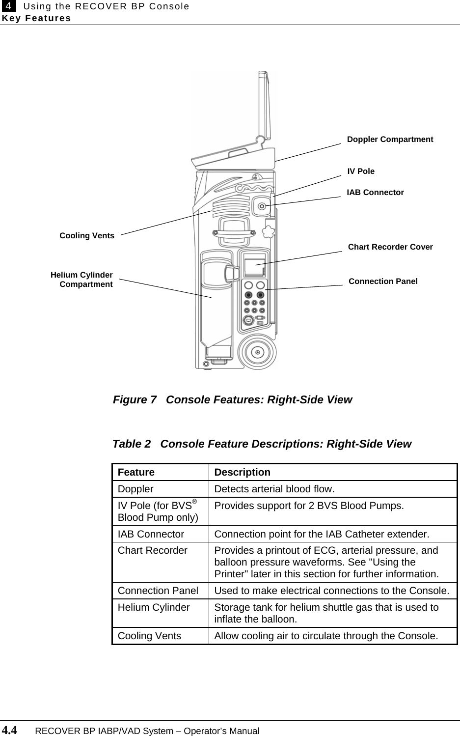
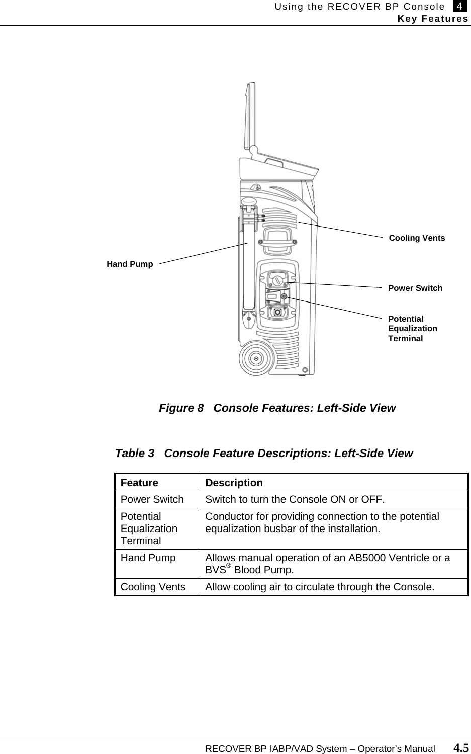
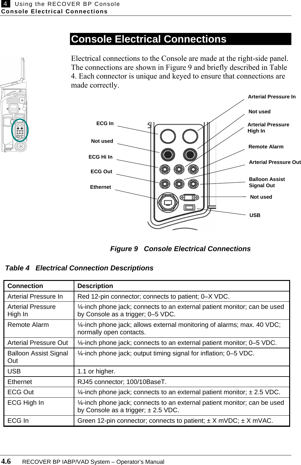
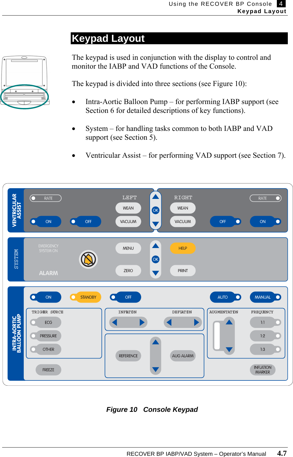
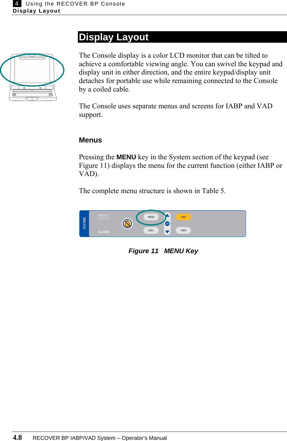
![IMPORTANT NOTICE: Read this entire manual before using the RECOVER BP IABP/VAD System. The RECOVER BP IABP/VAD System is to be used only in accordance with this manual and in conjunction with the RECOVER BP Intra-Aortic Balloon Catheter Instructions for Use ****[document number]. Information contained in this document is subject to change without notice. © 2006 ABIOMED, Inc. All rights reserved. ABIOMED is a trademark of ABIOMED, Inc. and is registered in the U.S.A.](https://usermanual.wiki/ABIOMED/0036-0010/User-Guide-730121-Page-4.png)
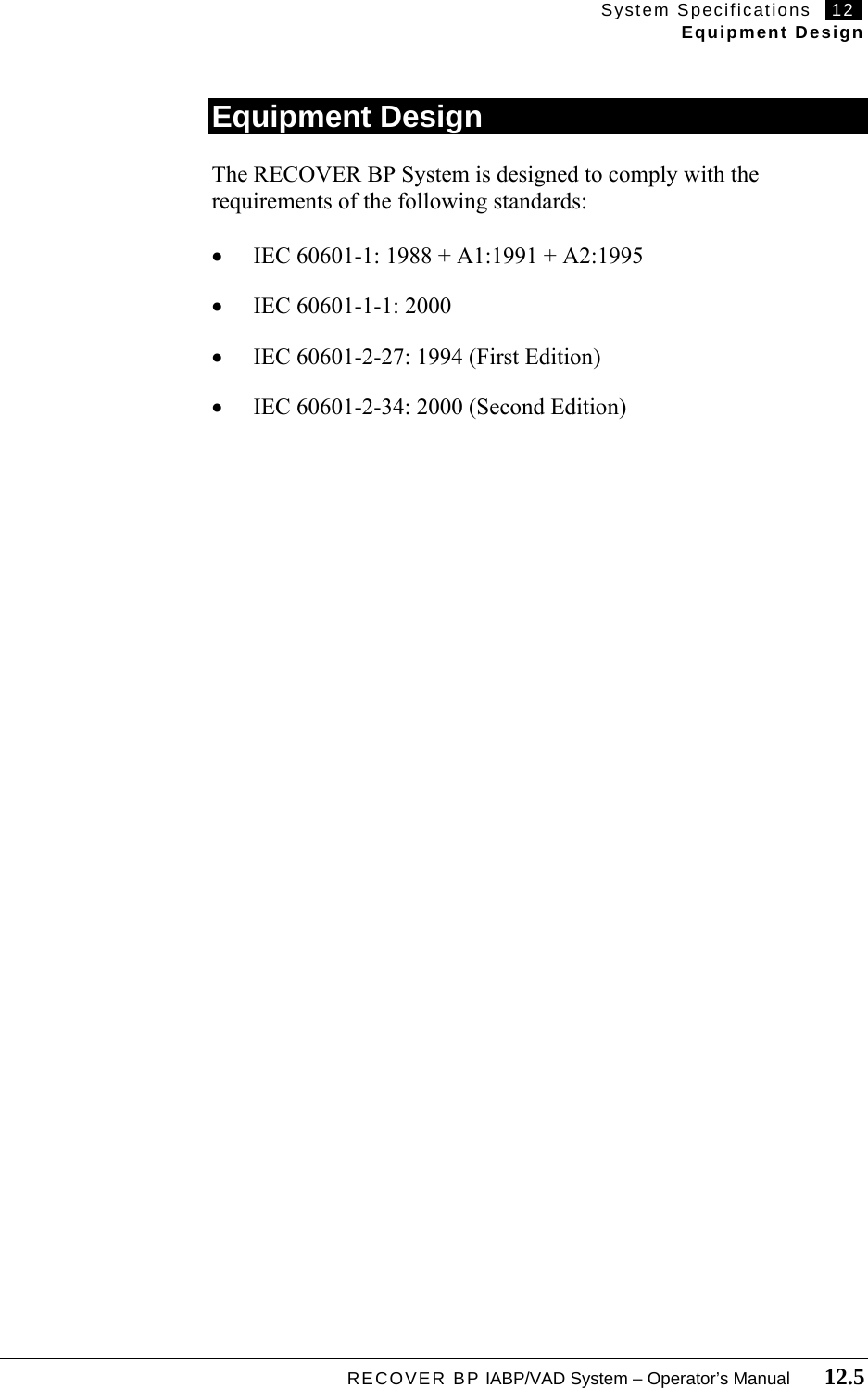
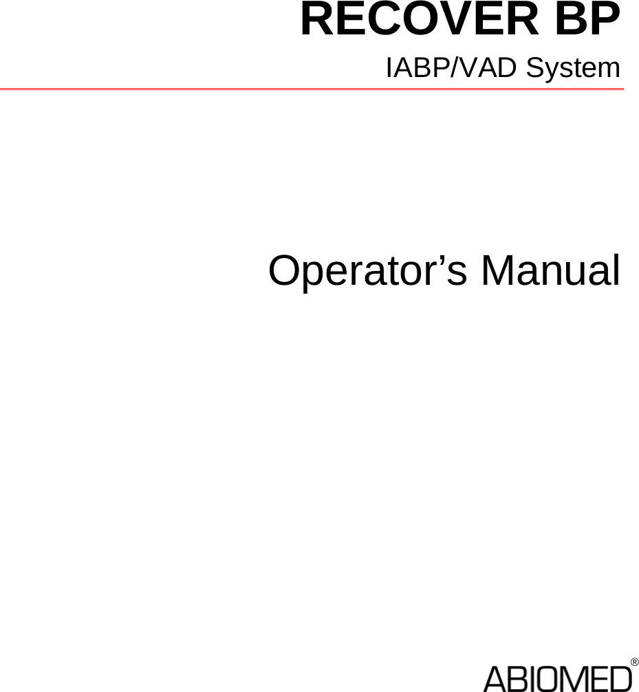
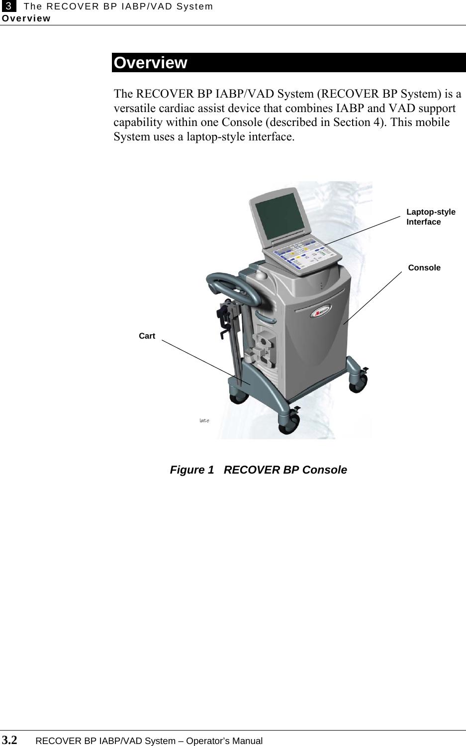
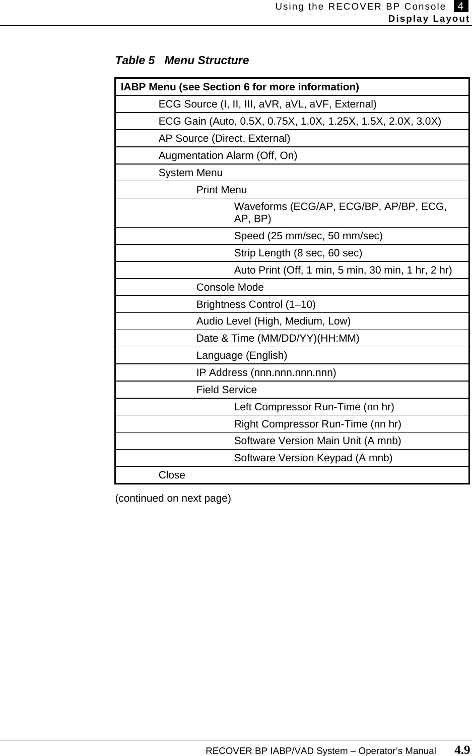
![ix Introduction This manual provides instructions for operating the RECOVER BP IABP/VAD System (RECOVER BP System or System). It is intended to be used in conjunction with the RECOVER BP Intra-Aortic Balloon Catheter Instructions for Use ****[add document number]. The following information summarizes the contents of each section: • Section 1 (Warnings and Cautions) lists the warnings and cautions pertaining to the use of the RECOVER BP System. • Section 2 (Indications, Contraindications, and Potential Adverse Events) discusses indications for use of the System and potential adverse events that may be associated with it. • Section 3 (The RECOVER BP IABP/VAD System) provides an overview of the System and associated products. • Section 4 (Using the RECOVER BP Console) describes the features, connections, and layout of the RECOVER BP Console (Console). • Section 5 (System Status and Settings) describes the handling of tasks common to both IABP and VAD support. • Section 6 (IABP Support) describes the procedures for providing IABP support. • Section 7 (VAD Support) describes the procedures for providing VAD support. • Section 8 (Emergency System Operation [ESO]) describes Emergency System Operation for both IABP and VAD support. • Section 9 (Installation and Maintenance) provides information on installation, cleaning, and preventive maintenance. • Section 10 (Abbreviations and Symbols) explains the symbols and abbreviations used on the System. • Section 11 (System Specifications) provides technical information pertaining to the System.](https://usermanual.wiki/ABIOMED/0036-0010/User-Guide-730121-Page-11.png)

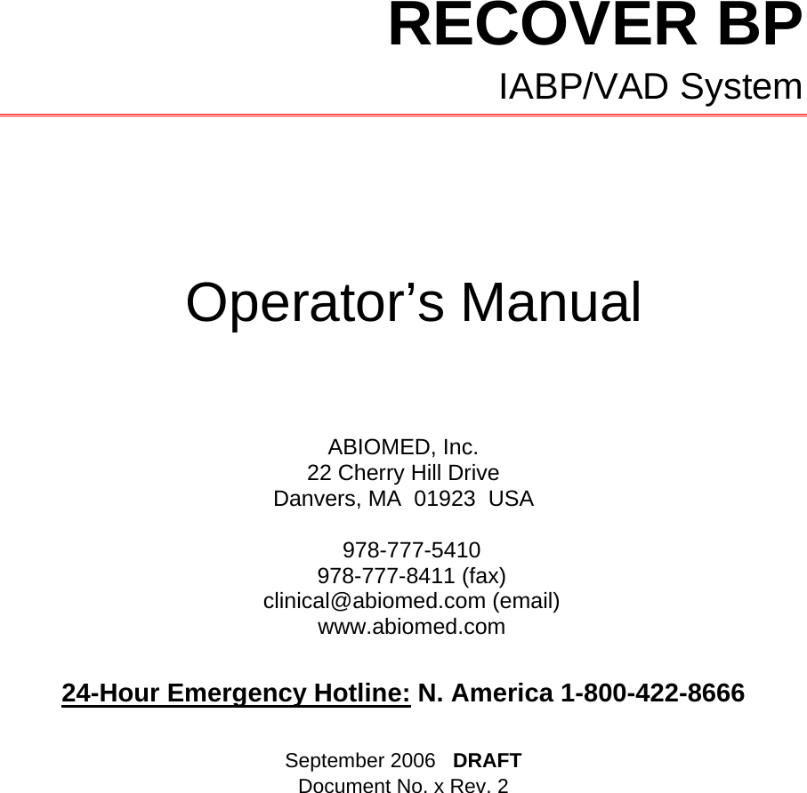
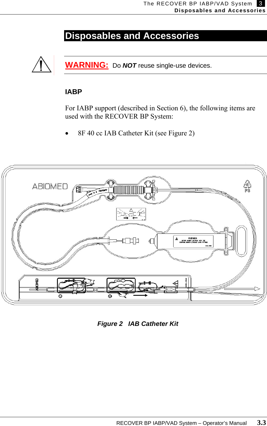
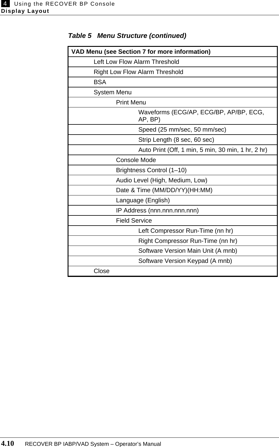
![2 Indications, Contraindications, and Potential Adverse Events Contraindications 2.4 RECOVER BP IABP/VAD System – Operator’s Manual Contraindications IABP • Significant aortic valve insufficiency • Thoracic or abdominal aortic aneurysm • Severe **** (PVD) • Occluded aorta VAD • Major cardiac or extracardiac catastrophes occurring during operation or in the postoperative period that preclude survival such as uncontrolled hemorrhage, massive air embolization, interstitial pulmonary hemorrhage with inability to maintain adequate ventilation, pump oxygenator or perfusion difficulties, or massive transfusion reaction, hemolysis during bypass, or inadequate cannulation. • Central nervous system damage resulting in fixed and dilated pupils. Potential Adverse Events IABP • Limb ischemia • Aortic dissection • Thrombosis • Vascular injury • Balloon rupture • Infection • Thrombocytopenia • Hemorrhage VAD ****[clinical]](https://usermanual.wiki/ABIOMED/0036-0010/User-Guide-730121-Page-22.png)
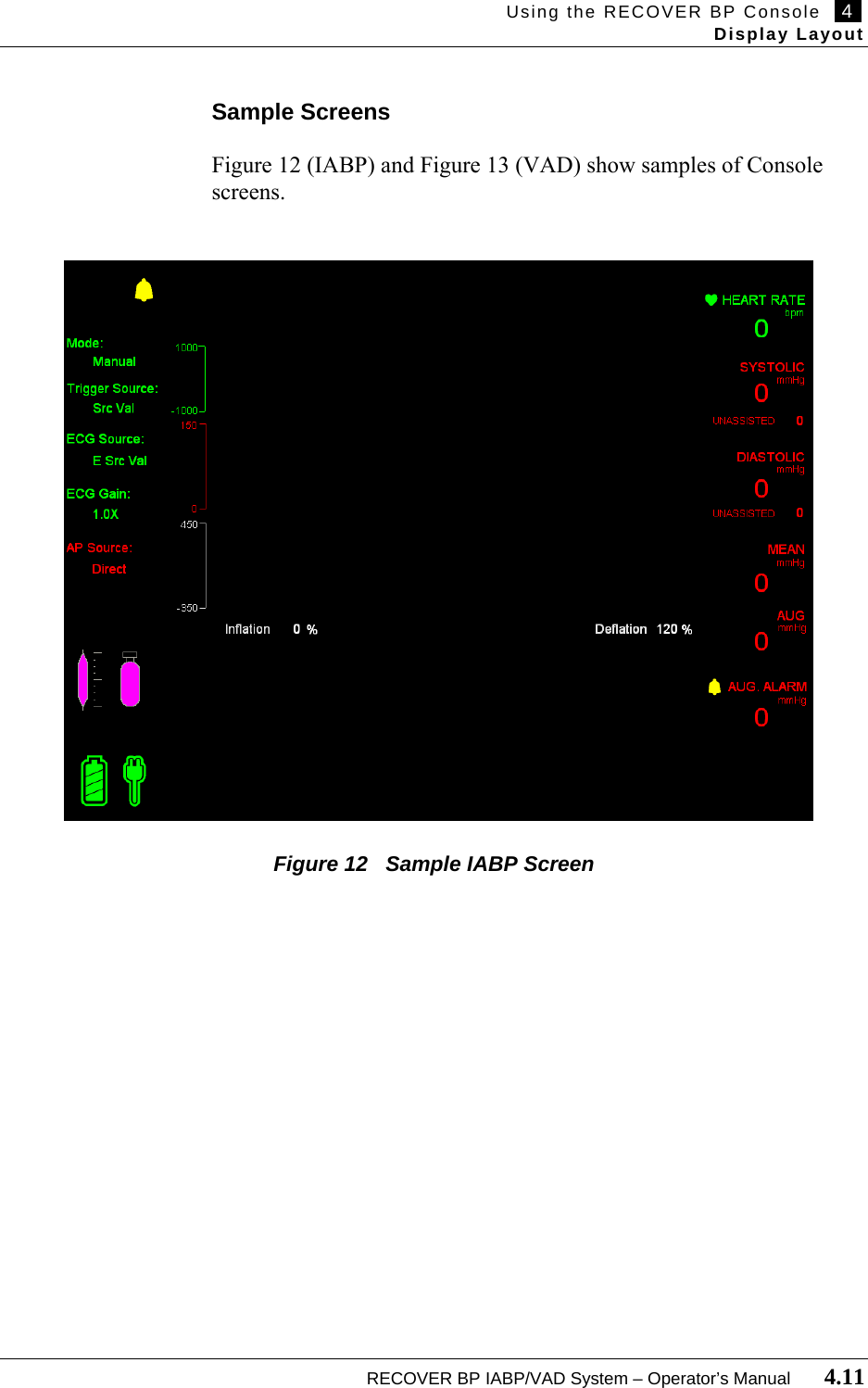

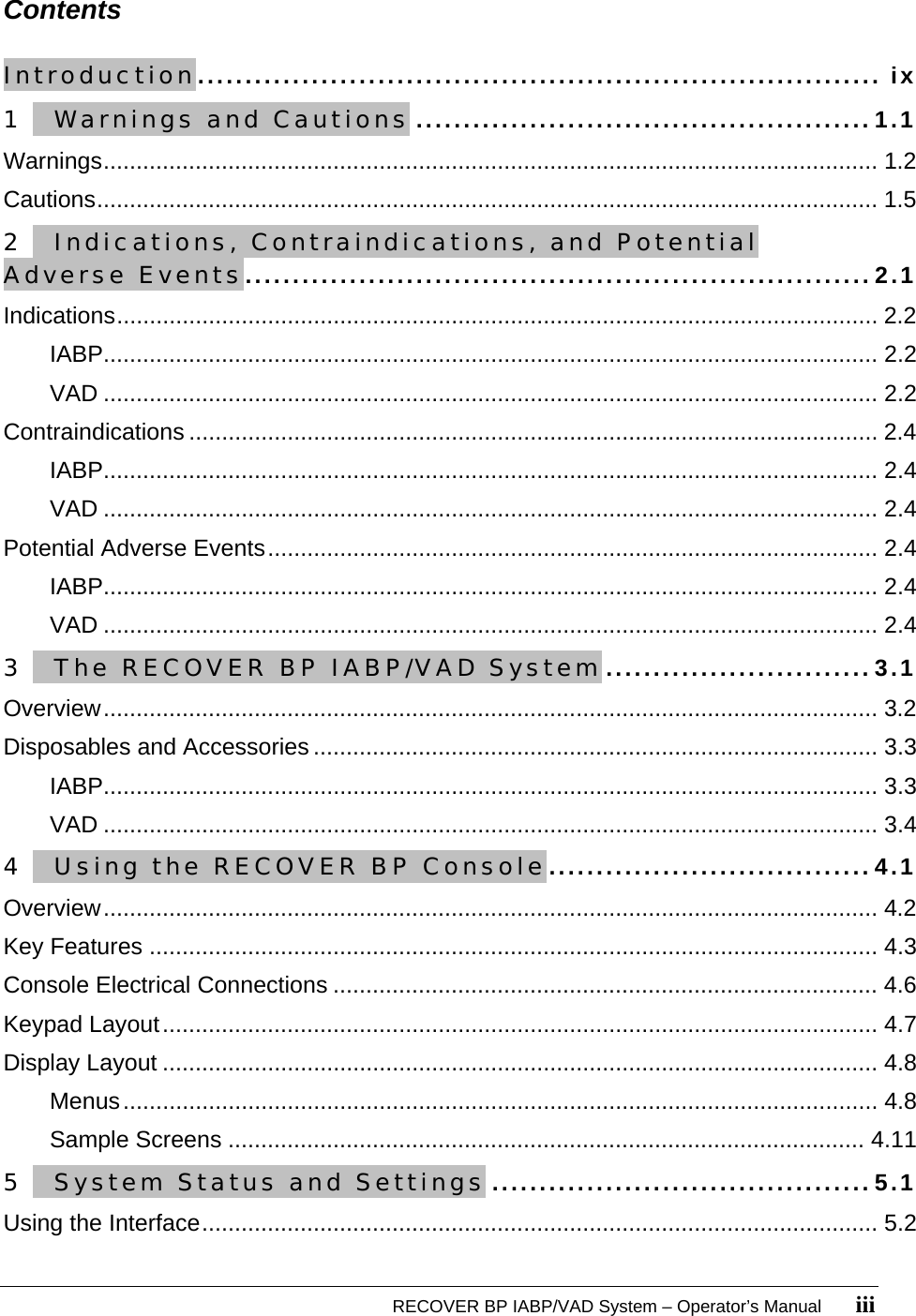
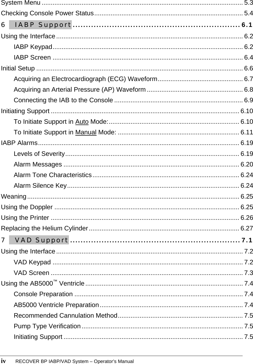
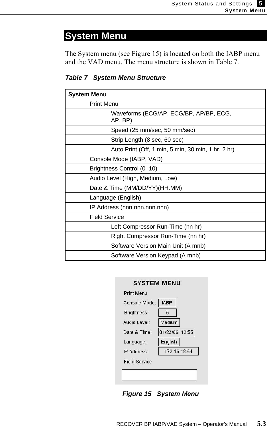
![5 System Status and Settings Using the Interface 5.2 RECOVER BP IABP/VAD System – Operator’s Manual Using the Interface The System section of the keypad (see Figure 14) is used for handling tasks common to both IABP and VAD support. These indicators and controls are described in Table 6. SYSTEM Figure 14 System Keypad Table 6 System Keypad Functions Feature Use Indicator Lights EMERGENCY SYSTEM ON Red light flashes when the Emergency System is operating. Refer to Section 8 for more information. ALARM Red light flashes when any alarm is active. Controls Silences the alarm for approximately 1 minute. MENU Displays the menu for the current function (IABP or VAD). ZERO Zeroes the arterial pressure (AP) transducer. HELP Displays help text for handling VAD alarms. PRINT Prints per the current Print settings. Navigates through the selected function. Selects the highlighted function. Navigates through the selected function. ****[SYSTEM label]](https://usermanual.wiki/ABIOMED/0036-0010/User-Guide-730121-Page-42.png)
![5 System Status and Settings Checking Console Power Status 5.4 RECOVER BP IABP/VAD System – Operator’s Manual Checking Console Power Status The Console runs on either AC power or its internal battery. It continuously charges the battery, which requires approximately 16 hours to recharge after depletion, while it is plugged into AC power. A fully charged battery will power the Console for one hour. You can check on Console power status in two places: • Two power status icons in the lower left corner of the IABP and VAD screens. • Three power status indicator lights on the front of the Console just below the keypad ****[see Figure x]. Tables 8 and 9 describe the information provided in these two locations.](https://usermanual.wiki/ABIOMED/0036-0010/User-Guide-730121-Page-44.png)
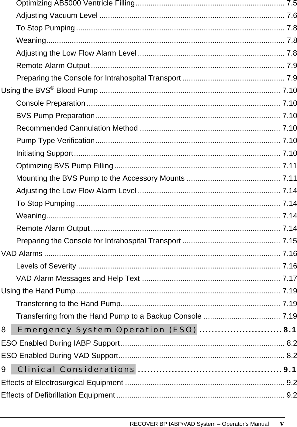
![System Status and Settings 5 Checking Console Power Status RECOVER BP IABP/VAD System – Operator’s Manual 5.5 Table 8 Power Status Indicated by the IABP and VAD Screens Battery Icon AC Power Icon Meaning Console is using AC power (halo showing). Console Battery is fully charged (all segments filled) but not in use (no halo). Using Battery power. Battery is fully charged. AC power is unplugged. Using Battery power. Battery is about ¾ charged. AC power is unplugged. Using AC power. Battery is about ½ charged. Using Battery power. Battery charge is low (icon flashes). AC power is unplugged. Using Battery power. Battery charge is critically low (icon flashes). AC power is unplugged. ****[1 hour VAD, 2 hours IABP?] Table 9 Power Status Shown by the Power Status Indicators Power Status Indicator and Condition Meaning AC Power – green Console is using AC power. Battery – amber Console is unplugged from AC power and has automatically switched to battery power. Battery – red Approximately 30 minutes of battery power remaining. AC Power – green and Charging – amber Console is using AC power. Battery charge level is at approximately 80%. AC Power – green and Battery – red Possible battery fault.](https://usermanual.wiki/ABIOMED/0036-0010/User-Guide-730121-Page-45.png)
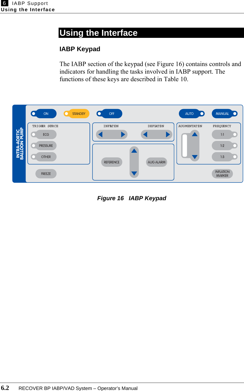
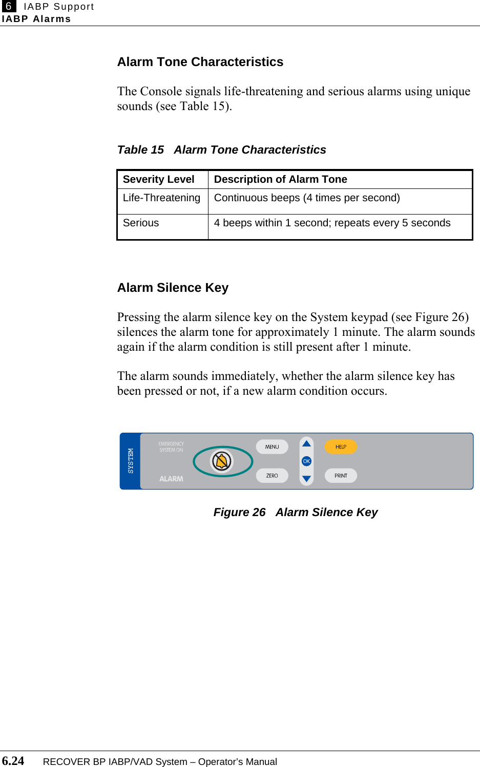
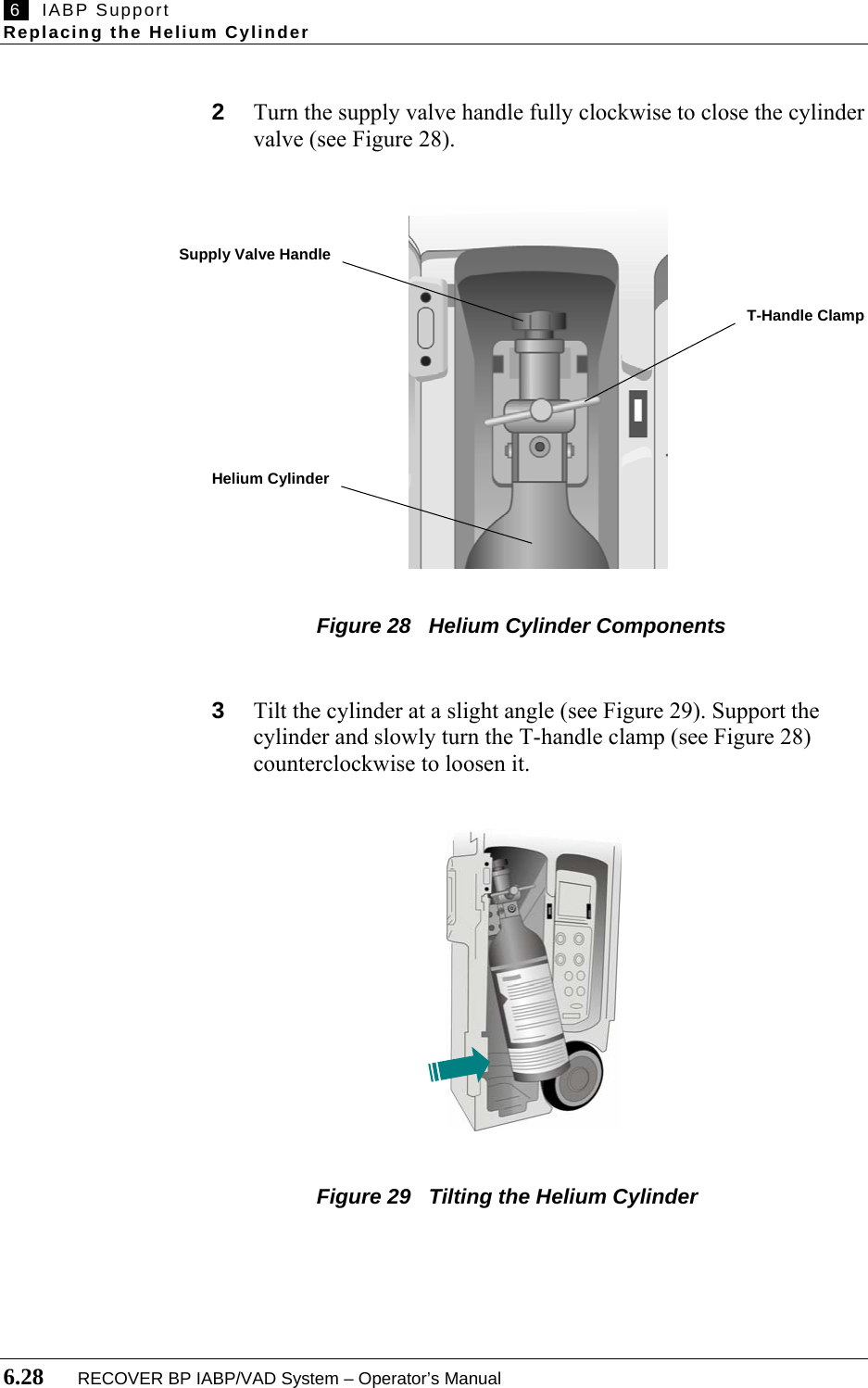
![IABP Support 6 Using the Interface RECOVER BP IABP/VAD System – Operator’s Manual 6.3 Table 10 IABP Keypad Functions Feature Use Control Keys ON Purges the pneumatic system and starts pumping. STANDBY Pauses pumping but keeps the Console ready to immediately resume pumping. Pumping resumes when ON is pressed. OFF Stops pumping when pressed twice within 13 seconds. AUTO Automatically selects optimal ECG source, ECG gain, AP source, trigger source, inflation timing, and deflation timing. MANUAL Allows you to select ECG source, AP source, trigger source, inflation timing, and deflation timing. ECG Selects ECG signal as the trigger source. PRESSURE Selects AP signal as the trigger source. OTHER Allows you to select Apace, Vpace, or Internal as the trigger source. FREEZE Freezes or unfreezes the display. INFLATE In MANUAL mode, the left and right arrows adjust the inflation interval. Inactive in AUTO mode. DEFLATE In MANUAL mode, the left and right arrows adjust the deflation interval. Inactive in AUTO mode. REFERENCE Up and down arrows select the reference line. AUG ALARM Up and down arrows set the augmentation alarm level. AUG Up and down arrows set the augmentation level. FREQ Selects assist frequency (1:1, 1:2, or 1:3). INFLATION MARKER Turns inflation marker on or off. Indicator Lights ON Green light when ON is pressed. STANDBY Amber light when STANDBY is pressed. OFF Red light flashes when OFF is pressed once (pumping does not stop). Light stays red when OFF is pressed twice within 13 seconds (pumping stops). AUTO Green light when AUTO is pressed. MANUAL Amber light when MANUAL is pressed. ECG Green light when ECG is selected as the trigger source. PRESSURE Green light when AP is selected as the trigger source. OTHER Green light when Apace, Vpace, or Internal is selected as the trigger source. AUGMENTATION Green light bar indicates augmentation level. FREQ Green light indicates the selected assist frequency (1:1, 1:2, or 1:3). ****[INTRA-AORTIC BALLOON PUMP label]](https://usermanual.wiki/ABIOMED/0036-0010/User-Guide-730121-Page-49.png)
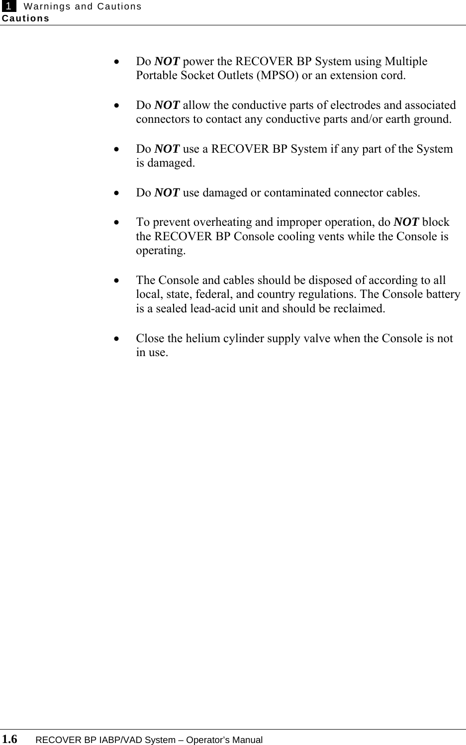
![6 IABP Support Initial Setup 6.6 RECOVER BP IABP/VAD System – Operator’s Manual Initial Setup WARNING: Do NOT power the RECOVER BP System using Multiple Portable Socket Outlets (MPSO) or an extension cord. WARNING: Pumping an IAB that has a leak can result in: (1) a blood clot in the IAB that may require surgical removal of the IAB, and (2) air embolism. WARNING: A patient monitor must be provided and used to continuously monitor patient physiological pressure. Do NOT rely solely on the System alarms to notify you of life-threatening conditions. 1 Plug the Console power cord into an AC outlet. 2 Turn the Console ON using the AC power switch on the left side. The Console goes through a Self-Test and is ready to use in approximately 25 seconds. Verify that the audible alarm indicator is operating properly by listening for the alarm tone during the Self-Test. NOTE: Upon power-up, the Console displays the same type of screen (IABP or VAD) used at shutdown. If necessary, change to IABP mode by pressing the MENU key and selecting System Menu > Console Mode > IABP. 3 Open the cover of the helium cylinder compartment. Turn the cylinder supply valve one-half turn counterclockwise to open the valve. Make sure the helium cylinder pressure reading on the left side of the display is at least ****[X] psi. Close the compartment cover.](https://usermanual.wiki/ABIOMED/0036-0010/User-Guide-730121-Page-52.png)
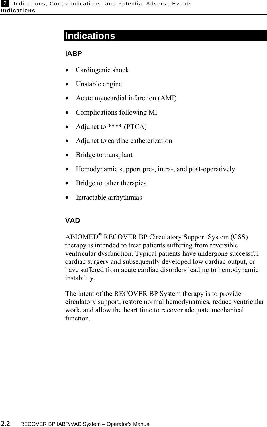
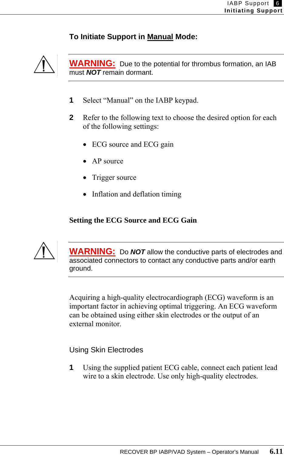
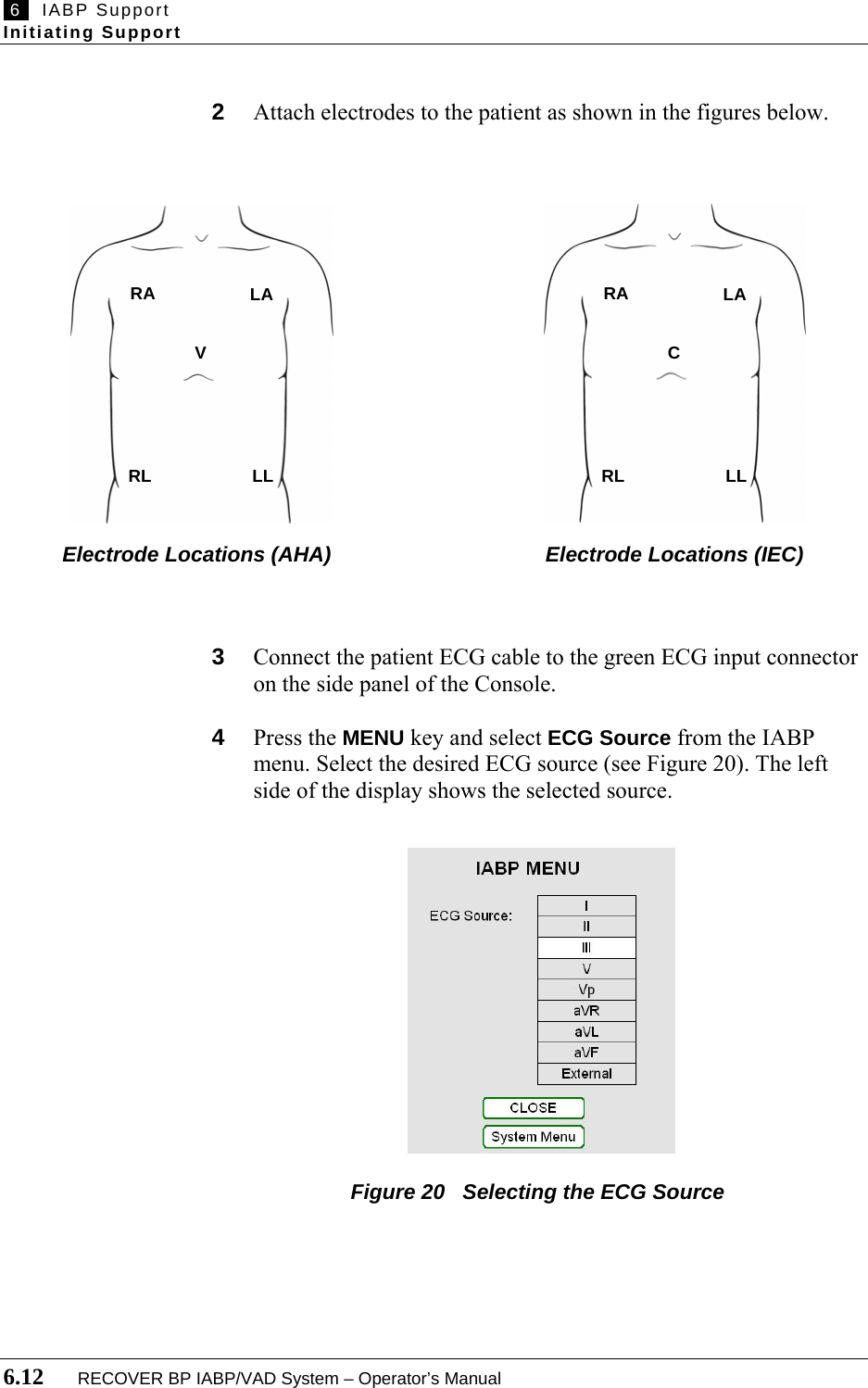
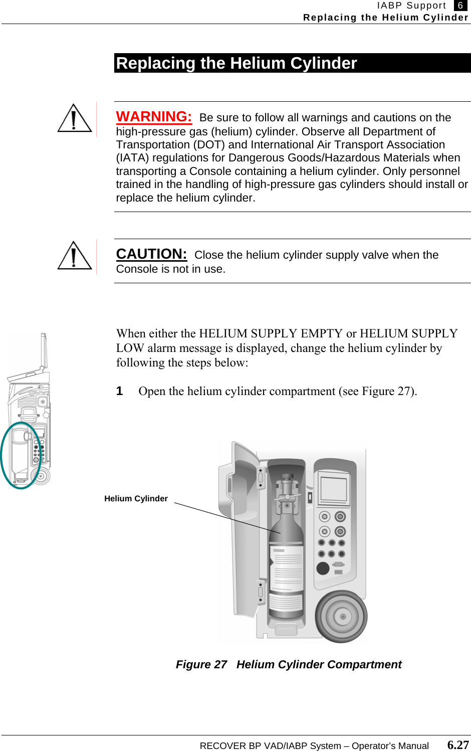
![IABP Support 6 Initial Setup RECOVER BP IABP/VAD System – Operator’s Manual 6.7 NOTE: If the helium cylinder pressure is less than ****[X] psi, change the cylinder by following the steps in "Replacing the Helium Cylinder" in this Section. Acquiring an Electrocardiograph (ECG) Waveform WARNING: Do NOT allow the conductive parts of electrodes and associated connectors to contact any conductive parts and/or earth ground. Acquiring a high-quality electrocardiograph (ECG) waveform is an important factor in achieving optimal triggering. An ECG waveform can be obtained using either skin electrodes or the output of an external monitor. Using Skin Electrodes 1 Using the supplied patient ECG cable, connect each patient lead wire to a skin electrode. Use only high-quality electrodes. 2 Attach electrodes to the patient as shown in the figures below. Figure 18 Electrode Locations (AHA) Figure 19 Electrode Locations (IEC) RA LA V RL LL RA LA C RL LL](https://usermanual.wiki/ABIOMED/0036-0010/User-Guide-730121-Page-53.png)
![IABP Support 6 Initial Setup RECOVER BP IABP/VAD System – Operator’s Manual 6.9 1 Place a pressure catheter at the chosen location. 2 Connect the pressure catheter to the pressure transducer. 3 Zero the pressure transducer by pressing ZERO on the System keypad. 4 Check that the peak and mean systolic/diastolic pressures are displayed. 5 Check that the arterial pressure waveform is displayed after the IAB is inserted. ****[mention heparin?] Using an External Monitor 1 Connect the AP high-level input interface cable between the external patient monitor and the high-level AP input on the side panel. Make sure that ****[X] is selected on the display. 2 Check that the arterial pressure waveform is properly displayed. Connecting the IAB to the Console 1 Remove the plug from the IAB extender input connector. 2 Connect the Console extension tubing to the IAB. 3 Connect the Console extension tubing to the Console IAB connector. 4 Verify that the correct IAB size is shown on the left side of the display. 5 Verify that the augmentation level is set at maximum.](https://usermanual.wiki/ABIOMED/0036-0010/User-Guide-730121-Page-55.png)
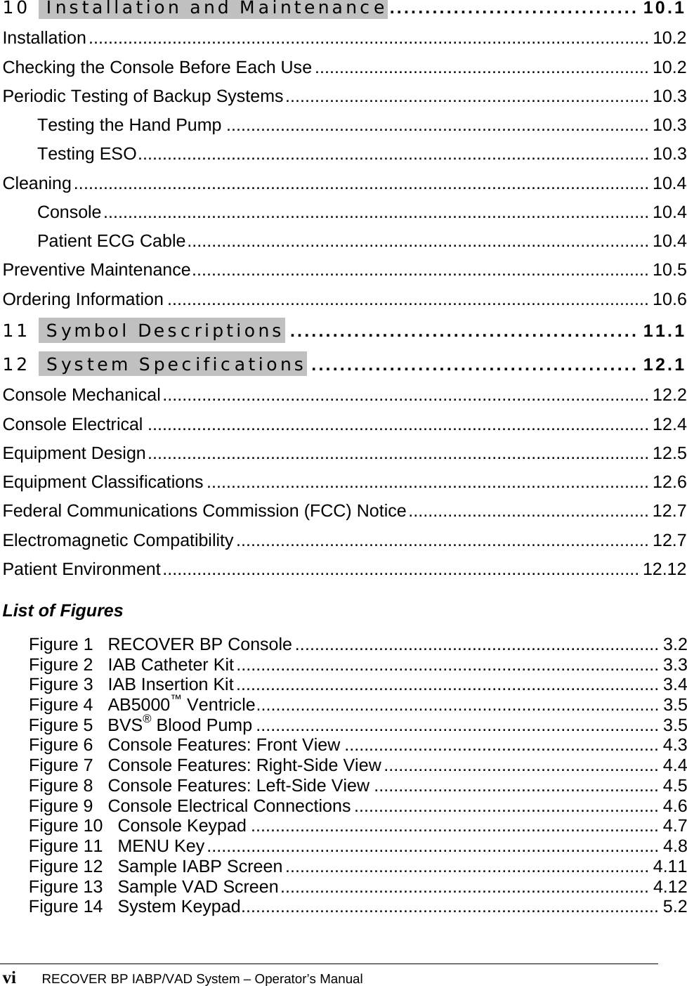
![6 IABP Support Initiating Support 6.14 RECOVER BP IABP/VAD System – Operator’s Manual Setting the AP Source Using a Pressure Transducer NOTE: Refer to the Edwards Lifesciences Instructions for Use for important information on using the TruWave Disposable Pressure Transducer. Also refer to this document for volumetric displacement information. 1 Connect the transducer cable to the red AP connector on the side panel. 2 Press the MENU key and select AP Source > Direct (see Figure 22). The left side of the display shows the selected AP source. ****[delete AP Source white background] Figure 22 Selecting the AP Source for a Transducer 3 Check that the arterial pressure waveform is displayed.](https://usermanual.wiki/ABIOMED/0036-0010/User-Guide-730121-Page-60.png)
![IABP Support 6 Initiating Support RECOVER BP IABP/VAD System – Operator’s Manual 6.15 Using an External Monitor 1 Connect the AP high-level input interface cable between the external patient monitor and the high-level AP input on the side panel. Make sure that ****[X] is selected on the display. 2 Press the MENU key and select AP Source > External (see Figure 23). The left side of the display shows the selected AP source. Figure 23 Selecting the AP Source for an External Monitor 3 Check that the arterial pressure waveform is properly displayed. Selecting the Trigger Source ECG Using this setting, the Console triggers on the QRS and ignores pacemaker pulses. Select this option under TRIGGER SOURCE on the keypad.](https://usermanual.wiki/ABIOMED/0036-0010/User-Guide-730121-Page-61.png)
![6 IABP Support Initiating Support 6.16 RECOVER BP IABP/VAD System – Operator’s Manual Pressure WARNING: When pressure triggering is used, adjust deflation to be complete at the upstroke of systole. WARNING: Do NOT use pressure triggering while arrhythmia is present. The Console triggers on the arterial pressure waveform. Select this option under TRIGGER SOURCE on the keypad. Apace The Console triggers on a pacer. Select this option by choosing Other (under TRIGGER SOURCE) and then selecting Apace from the Trigger Source Other Selection menu. Figure 24 Selecting Apace as the Trigger Source Make sure that the pacemaker pulses are being detected by ****[X]. The Apace signal must have an amplitude of ****[X] µV minimum and a pulse duration of ****[X] ms minimum.](https://usermanual.wiki/ABIOMED/0036-0010/User-Guide-730121-Page-62.png)
![IABP Support 6 Initiating Support RECOVER BP IABP/VAD System – Operator’s Manual 6.17 Vpace The Console triggers on the ventricular waveform of the pacer. You can choose this option by selecting Other (under TRIGGER SOURCE) and then selecting Vpace from the Trigger Source Other Selection menu. Make sure that the pacemaker pulses are being detected by ****[X]. The Vpace signal must have an amplitude of ****[X] µV minimum and a pulse width of ****[X] ms minimum. Internal WARNING: Do NOT use Internal trigger source while the patient is producing cardiac output. Use this setting when there is no cardiac cycle. Choose this option by pressing Other (under TRIGGER SOURCE) and selecting Internal. If an ECG signal is detected while the internal trigger is in use, the system sounds an alarm, at which time the trigger source should be changed to ECG for optimal triggering. NOTE: Check that the selected trigger source is shown on the left side of the display.](https://usermanual.wiki/ABIOMED/0036-0010/User-Guide-730121-Page-63.png)
![6 IABP Support Initiating Support 6.18 RECOVER BP IABP/VAD System – Operator’s Manual Setting Inflation and Deflation Timing WARNING: If the heart rate varies by more than 10 beats per minute (bpm) within ****[X] seconds, evaluate inflation and deflation timing and make adjustments if necessary. 1 Press the ON key on the IABP keypad. The Console purges the IAB Catheter, fills the Catheter with helium, and begins pumping on the IAB. 2 ****[Initial timing procedure and graphic] NOTE: The Console automatically empties and refills the IAB every two hours, after which support automatically resumes. Inflation Timing Use the left and right INFLATE keys to adjust the inflation timing until the highlighted segment of the arterial pressure trace begins at the dicrotic notch. ****[Timing graphic] Deflation Timing Use the left and right DEFLATE keys to adjust the deflation timing until the end of the highlighted segment of the arterial pressure trace is just prior to ventricular ejection. ****[Timing graphic] — This completes the steps for initiating support in Manual mode. —](https://usermanual.wiki/ABIOMED/0036-0010/User-Guide-730121-Page-64.png)
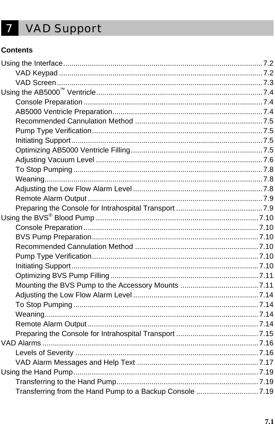
![7 VAD Support Using the Interface 7.2 RECOVER BP IABP/VAD System – Operator’s Manual Using the Interface VAD Keypad The elements of the Ventricular Assist section of the keypad (see Figure 30) are described in Table 16. RIGHTLEFT Figure 30 VAD Keypad Table 16 VAD Keypad Functions Feature Use Indicator Lights (LEFT and RIGHT) RATE Amber light flashes with each beat. ON Green light when ON is pressed. OFF Red light flashes when OFF is pressed once (pumping is not stopped). Light stays red when OFF is pressed twice within 13 seconds (pumping is stopped). Controls (LEFT and RIGHT) ON Starts pumping. OFF Stops pumping when pressed twice within 13 seconds. WEAN Displays weaning menu. VACUUM Displays vacuum menu. Navigation Controls Navigates through the selected function. Selects the highlighted function. Navigates through the selected function. ****[VENTRICULAR ASSIST label]](https://usermanual.wiki/ABIOMED/0036-0010/User-Guide-730121-Page-78.png)
![VAD Support 7 Using the AB5000™ Ventricle RECOVER BP IABP/VAD System – Operator’s Manual 7.7 Adjusting the Vacuum Level with Pumping Off Upon power-up (after completing its Self-Test), the Console displays the following screen: ****[Figure] The... indicate that the vacuum level is set to the default level of 100 mmHg (1.9 psi). Press the pump ON button if no reduction in vacuum level is needed. ****[vacuum level adjustment] In the following example, the vacuum level has been set to 50 mmHg (1.0 psi): ****[Figure] Adjusting the vacuum level on one side does not affect the vacuum level on the other side. The user-set vacuum level is applied to the Ventricle after its electrical/pneumatic connector is attached to the Console and the pump ON button is pressed. If pumping is inadvertently started before plugging in the Ventricle electrical/pneumatic connector, an alarm is generated instructing you to "Turn Pumping OFF and then ON" to recognize that a Ventricle is attached. User-set vacuum levels are saved during these transitions and applied to operation of the Ventricle. Adjusting the Vacuum Level with Pumping ON If no vacuum level is set by the user during startup, the default vacuum level of 100 mmHg (1.9 psi) is automatically selected (after the Ventricle electrical/pneumatic connector is attached to the Console and the pump ON button is pressed).](https://usermanual.wiki/ABIOMED/0036-0010/User-Guide-730121-Page-83.png)
![7 VAD Support Using the AB5000™ Ventricle 7.8 RECOVER BP IABP/VAD System – Operator’s Manual In the following example, a Ventricle is pumping on the left side. The vacuum setting is at the default 100 mmHg (1.9 psi) level. ****[Figure] ****[vacuum level adjustment] In the following example, a Ventricle is pumping on the left side with the vacuum level set to 35 mmHg (0.7 psi): ****[Figure] To Stop Pumping To stop pumping, press the appropriate ON button twice within 13 seconds. You must press the button twice to stop the pump (see Figure ****X). This is a safety feature to prevent accidental operation. ****[Figure] Weaning When the patient is to be weaned, the Ventricle output may be set at any desired flow from 2.0 L/min to full flow (in 0.1 L/min. increments). ****[Selecting desired flow rate] ****[Figure] During the weaning operation, the Console’s displayed flow may vary for several beats from the selected flow setting. This may occur when patient conditions change and/or when the Console periodically adjusts Ventricle ejection duration to optimize flow. However, actual Ventricle flow will correspond to the selected flow setting. Adjusting the Low Flow Alarm Level The low flow alarm level can be adjusted when pumping is ON. It can be set to any level (in 0.1 L/min steps) between the current flow rate and 1.8 L/min during normal operation or 1.5 L/min in the weaning mode.](https://usermanual.wiki/ABIOMED/0036-0010/User-Guide-730121-Page-84.png)
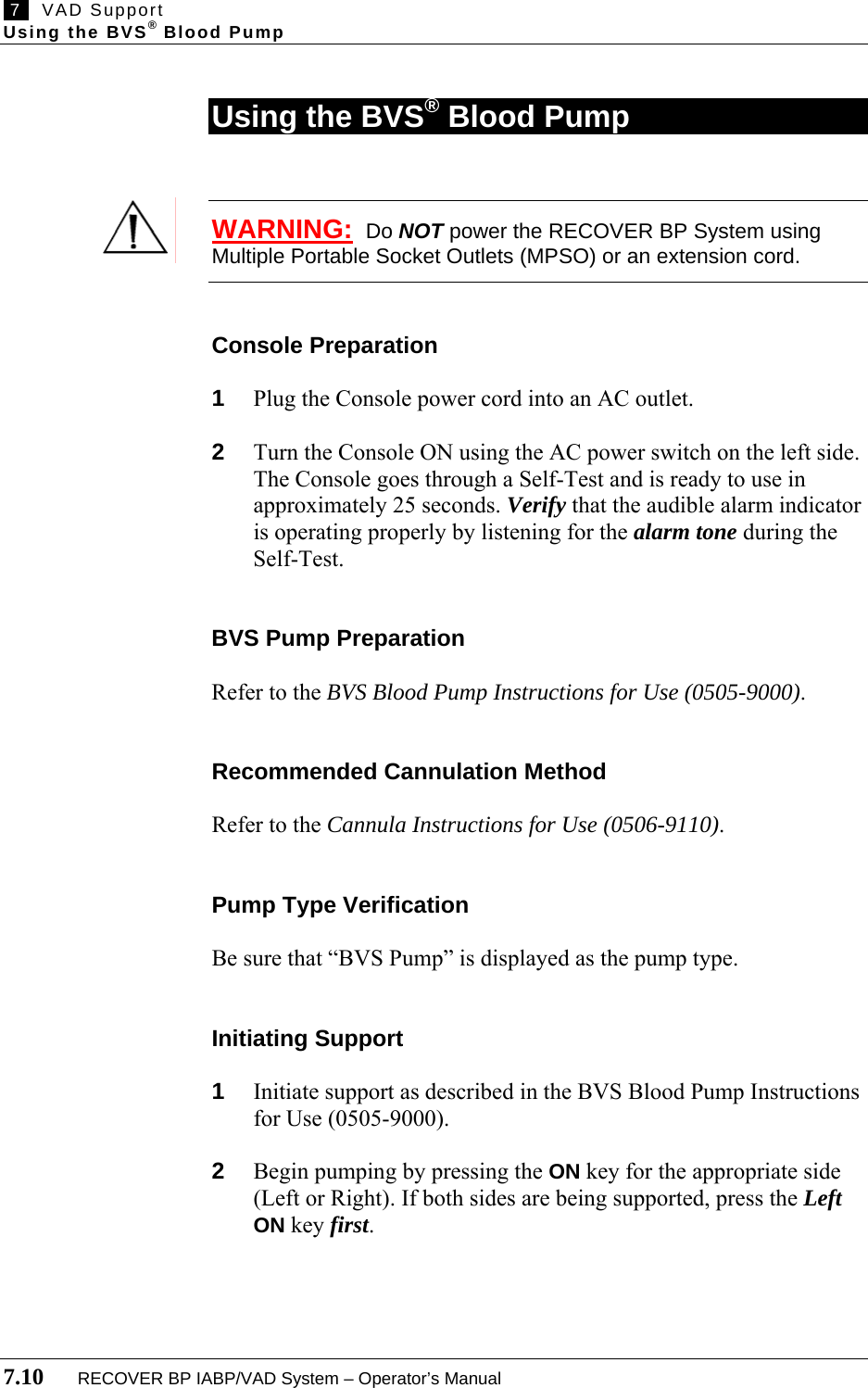
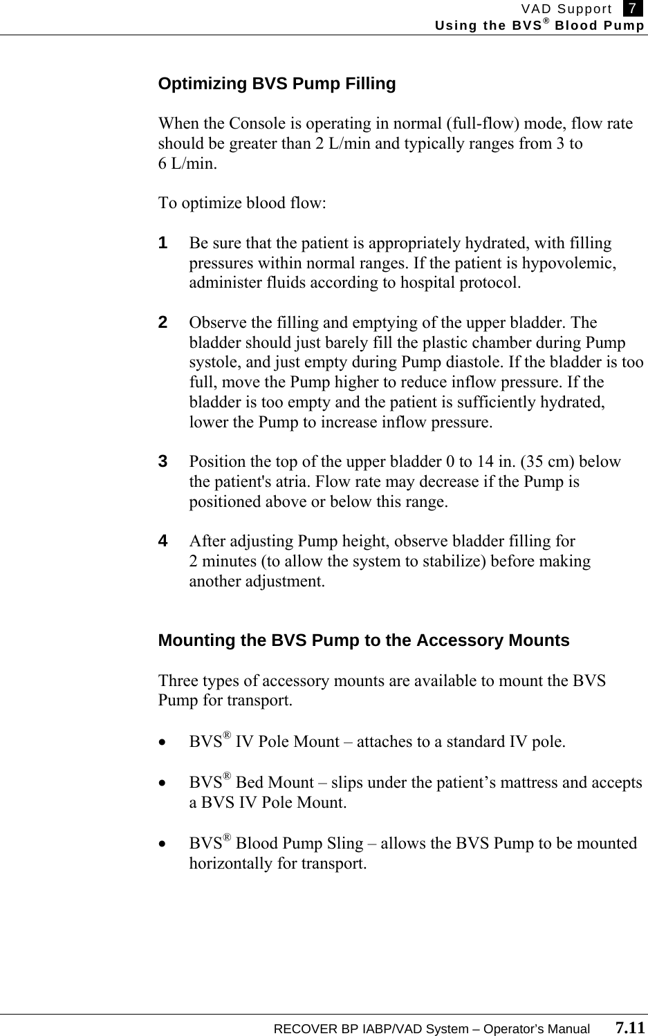

![VAD Support 7 Using the BVS® Blood Pump RECOVER BP IABP/VAD System – Operator’s Manual 7.13 8 Turn the central adjustment lever clockwise, back to its original position, to secure the Pole Mount in place. Attaching the BVS Pump to the BVS® IV Pole Mount A long plastic plate is attached to the back of the BVS Pump. At the top of this plate, slightly above the upper inflow bladder, is a square back plate designed to slide into the Pump bracket. 1 Hold the BVS Pump securely so the inflow and outflow tubing is at the top of the Pump and the driveline is at the bottom. 2 Slide the back plate into one of the Pump brackets from the top down. 3 Make sure that both edges of the Pump bracket fully engage the Pump back plate to ensure that it is attached securely. ****[Adjusting the Pump height] Attaching the BVS Pump to the BVS® Blood Pump Sling 1 Always hold the BVS Pump below the patient's heart. 2 Lay the Pump into the Sling. Be careful not to kink or bend the blood or air tubing. 3 Close the Sling around the Pump by joining the two hook-and-loop fastening ends. 4 Attach the Sling to the bed or stretcher by fastening the mounting straps around the bed rail. ****[Adjusting the Pump height]](https://usermanual.wiki/ABIOMED/0036-0010/User-Guide-730121-Page-89.png)
![7 VAD Support Using the BVS® Blood Pump 7.14 RECOVER BP IABP/VAD System – Operator’s Manual Adjusting the Low Flow Alarm Level The low flow alarm level can be adjusted when pumping is ON. It can be set to any level (in 0.1 L/min steps) between the current flow rate and 1.8 L/min during normal operation (1.5 L/min in the weaning mode). ****[Adjusting the alarm level] To Stop Pumping To stop pumping, press the appropriate OFF button twice within 13 seconds. You must press the button twice to stop the pump (see Figure ****X). This is a safety feature to prevent accidental operation. Weaning When the patient is to be weaned, the BVS Pump output may be set at any desired flow from 2.0 L/min to full flow (in 0.1 L/min. steps). ****[Selecting desired flow rate] [Figure] During the Weaning operation, the Console’s displayed flow may vary for several beats from the selected flow setting. This may occur when patient conditions change and/or when the Console periodically adjusts BVS Pump ejection duration to optimize flow. However, actual BVS Pump flow will correspond to the selected flow setting. Remote Alarm Output The remote alarm output allows the user to connect the Console to a remote call system. The remote alarm output jack is located on the right side of the Console and accepts a standard phone plug. The switch is normally open, but closes when an alarm is generated. This switch closure can be used to trigger an alarm via the remote call system.](https://usermanual.wiki/ABIOMED/0036-0010/User-Guide-730121-Page-90.png)

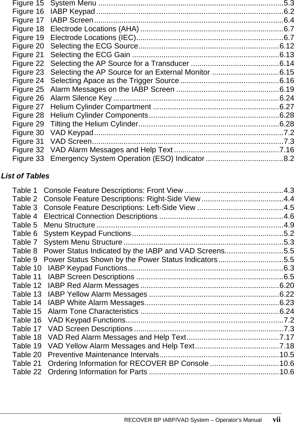
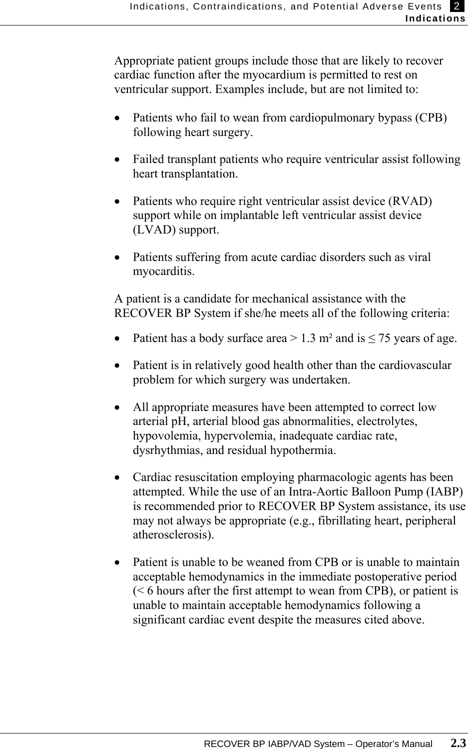
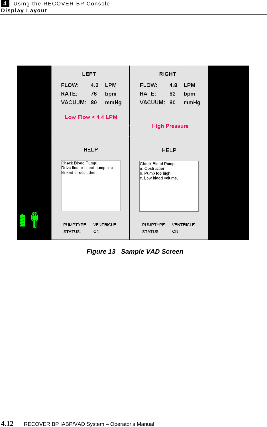
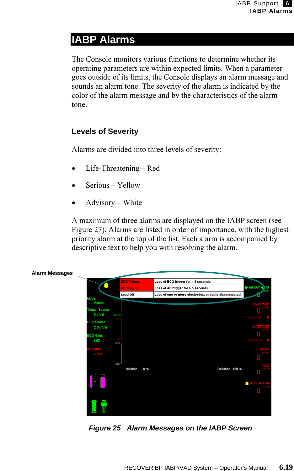
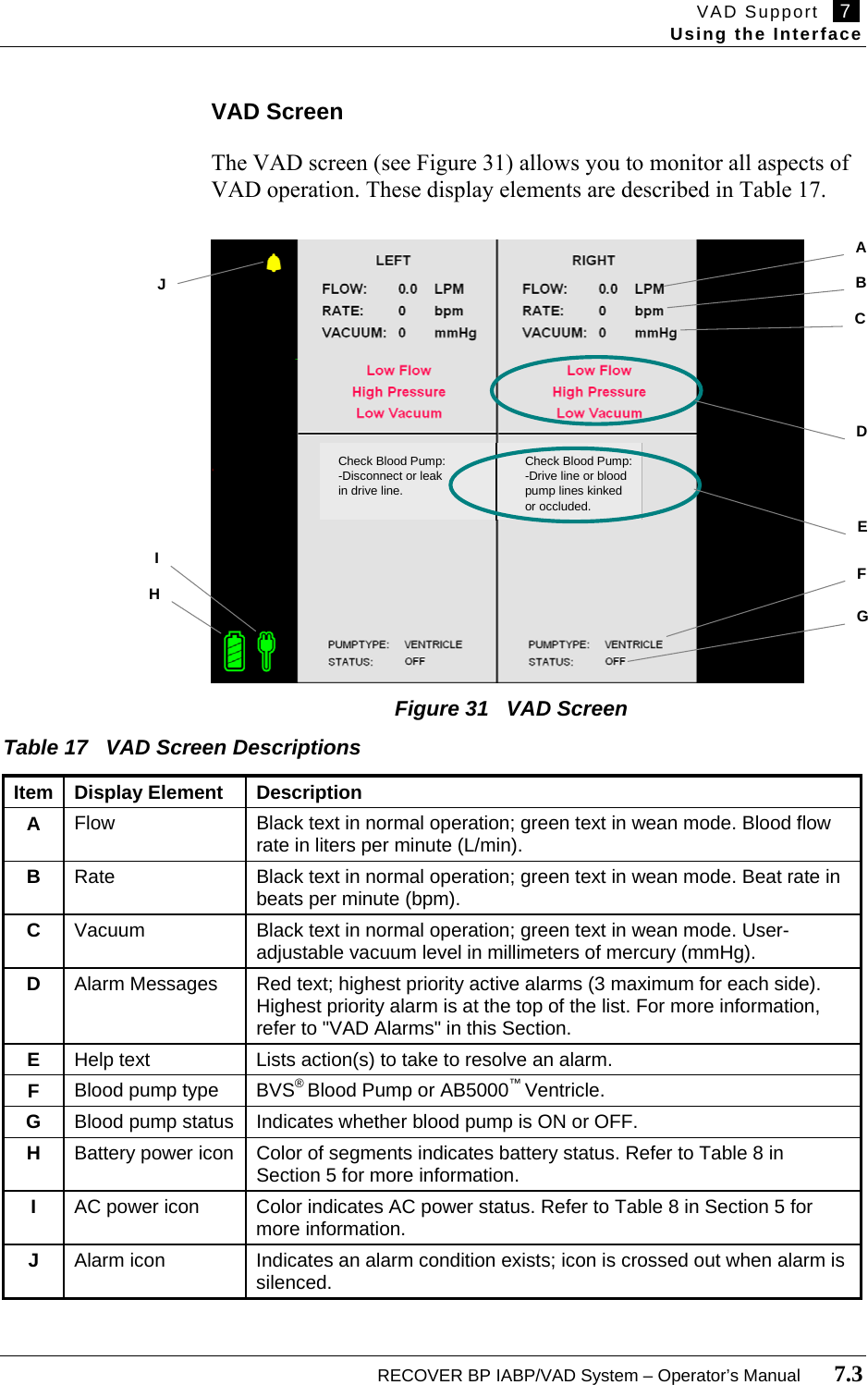
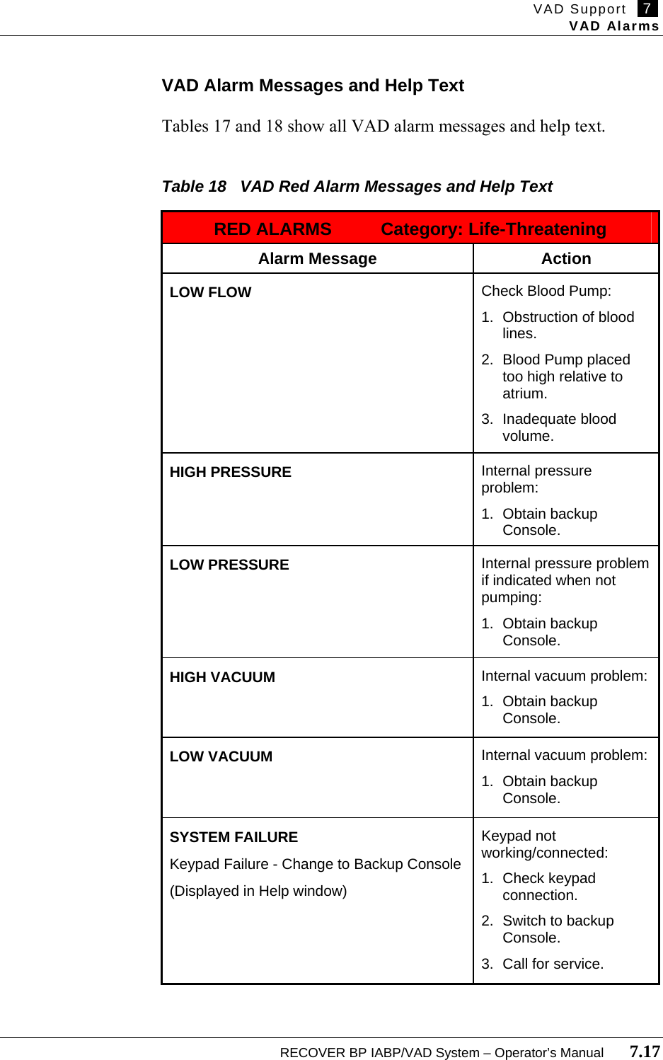
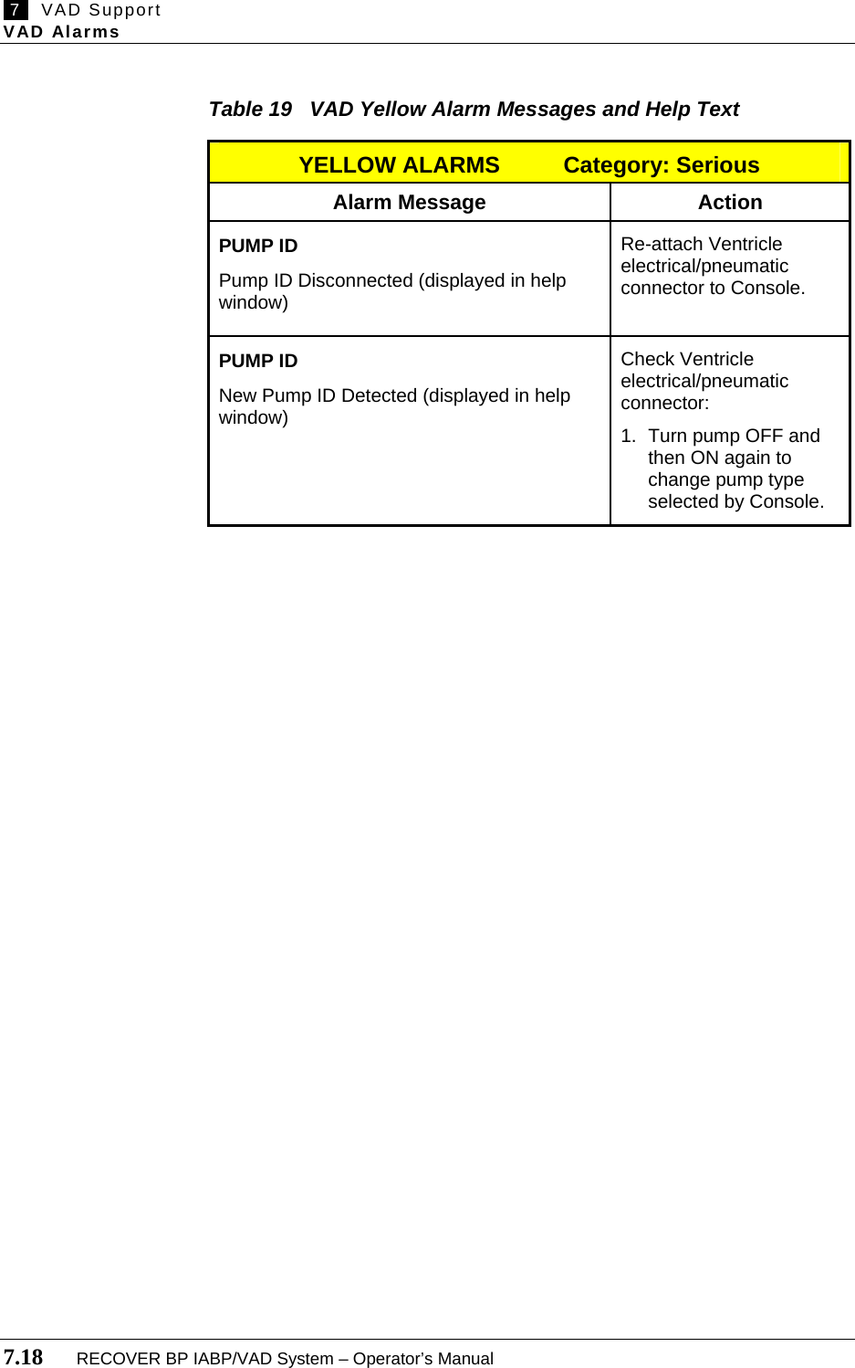
![7 VAD Support VAD Alarms 7.16 RECOVER BP IABP/VAD System – Operator’s Manual Check Blood Pump:-Disconnect or leakin drive line.Check Blood Pump:-Drive line or bloodpump lines kinkedor occluded. VAD Alarms The Console monitors various functions to determine whether its operating parameters are within expected limits. When a parameter goes outside of its limits, the Console displays an alarm message and sounds an alarm tone. The severity of the alarm is indicated by the color of the alarm message text and by the characteristics of the alarm tone ****[verify details]. Levels of Severity Alarms are divided into two levels of severity: • Life-Threatening – Red • Serious – Yellow A maximum of six alarms (three Left and three Right) are displayed on the VAD screen (see Figure 32). When an alarm condition occurs, pressing HELP on the System keypad opens a help window that describes the action(s) to take to resolve the alarm. Figure 32 VAD Alarm Messages and Help Text AlarmMessagesAction(s) to take to resolve the alarm](https://usermanual.wiki/ABIOMED/0036-0010/User-Guide-730121-Page-92.png)

![10 Installation and Maintenance Ordering Information 10.6 RECOVER BP IABP/VAD System – Operator’s Manual Ordering Information Table 21 Ordering Information for RECOVER BP Console Catalog No. Language Nominal Voltage 0036-0000 English 120 VAC ****[?] English 230 VAC Table 22 Ordering Information for Parts Catalog No. Description Contents 0036-0030 Cart 1 per box 0015-0040 Aircraft Mounting Plate 1 per box 0050-3200 BVS® Blood Pump Sling 1 per box 0005-0090 BVS® IV Pole Mount 1 per box 0005-0080 BVS® Bed Mount 1 per box 0005-0060 BVS® Pump Mount Set 1 per box 0036-2754 Patient Cable Set ****[?] ****[?] Edwards Lifesciences TruWave Disposable Pressure Transducer (supplied sterile) ****[?] 0036-6300 *Helium Cylinder, 93 L ****[?] 2500-0133 *Helium Yoke Sealing Washer ****[?] 2000-0009 Chart Recorder Paper, Thermal, 2-inch Roll ****[?] ****[?] Adapter for Datascope® 8F (40 cc) IAB Catheter ****[?] ****[?] RECOVER BP IABP/VAD System Operator's Manual 1 per box ****[?] RECOVER BP IABP/VAD System Service Manual 1 per box * This is a refillable cylinder. Ownership of this cylinder has been established by sale to the purchaser. Refill may be arranged by contacting your local gas supplier or by contacting Linde Specialty Gas Customer Service at 1-800-837-7226. Refiller is required to relabel this product with their own label. Do not refill without properly labeling. This cylinder may also be recycled by following the instructions below: 1. Using a properly installed regulator, slowly vent residual gas until empty. 2. Vent gas slowly into a well ventilated area, preferably outdoors. 3. Remove the regulator, let valve open. Write "EMPTY" on cylinder. 4. Deface any hazardous materials information labels. 5. Cylinder may be discarded as scrap metal or solid waste. 6. Check with local solid waste authority to ensure local regulatory compliance. 7. Questions? Contact Linde Specialty Gas Customer Service at 1-800-837-7226.](https://usermanual.wiki/ABIOMED/0036-0010/User-Guide-730121-Page-106.png)
![12 System Specifications Console Mechanical 12.2 RECOVER BP IABP/VAD System – Operator’s Manual Console Mechanical ****[reformat] Attribute Specification Temperature Operating: 10°C to 40°C (50°F to 104°F) Storage: -15°C to 50°C (5°F to 122°F) Relative Humidity Operating: 30% to 75% Storage: 10% to 95%, noncondensing Atmospheric Pressure Operating: 8000 ft (750 hPa) to -1000 ft (1050 hPa) Storage: 18,000 ft (500 hPa) to -1000 ft (1050 hPa) Dimensions – Transport & Hospital Configuration Transport (w/o Cart) Hospital (w/ Cart) Height: 34 in. (86.4 cm) 41 in. (104.1 cm) Width: 23 in. (58.4 cm) 28 in. (71.1 cm) Depth: 11 in. (27.9 cm) 18 in. (45.7 cm) Dimensions – Packaged Configuration Console Cart Height: 24 in. (61.0 cm) 28 in. (71.1 cm) Width: 30 in. (76.2 cm) 33 in. (83.8 cm) Depth: 38 in. (96.5 cm) 45 in. (114.3 cm) Weight – Transport & Hospital Configuration Transport (w/o Cart) Hospital (w/ Cart) Maximum: 126 lb (57.2 kg) 190 lb (86.2 kg) Weight – Packaged Configuration Console Cart Maximum: ****[X] lb ****[X] lb Left-Side Flow Rate Under normal operation, the Console must produce a minimum blood flow through the VAD for both pumps as follows: Minimum: 4.8 L/min at outflow pressure of 90 mmHg (1.7 psi) and inflow pressure > 10 mmHg (0.2 psi) for 42 Fr Atrial Cannula used with 42 Fr or 10 mm Arterial Cannula. Minimum: 4.0 L/min at outflow pressure of 90 mmHg (1.7 psi) and inflow pressure > 10 mmHg (0.2 psi) for 32 Fr and 36 Fr Atrial Cannula used with 42 Fr or 10 mm Arterial Cannula. Method: Blood flow rate calculated based on integration of airflow signal. Right-Side Flow Rate Under normal operation, the Console must produce a minimum blood flow through the VAD as follows: Minimum: 4.8 L/min at outflow pressure of 40 mmHg (0.8 psi) and inflow pressure > 10 mmHg (0.2 psi) for 42 Fr Atrial Cannula used with 42 Fr or 10 mm Arterial Cannula. Minimum: 4.0 L/min at outflow pressure of 40 mmHg (0.8 psi) and inflow pressure > 10 mmHg (0.2 psi) for 32 Fr and 36 Fr Atrial Cannula used with 42 Fr or 10 mm Arterial Cannula Method: Blood flow rate calculated based on integration of airflow signal.](https://usermanual.wiki/ABIOMED/0036-0010/User-Guide-730121-Page-110.png)
![System Specifications 12 Console Mechanical RECOVER BP IABP/VAD System – Operator’s Manual 12.3 Console Mechanical (continued) ****[reformat] Attribute Specification Displayed Flow Accuracy At altitudes between min/max range, flow accuracy is as follows: Left Side: ± 15% over the following ranges: Inflow Pressure 5 to 25 mmHg (0.1 to 0.5 psi) Outflow Pressure 60 to 90 mmHg (1.2 to 1.7 psi) Right Side: ± 15% over the following ranges: Inflow Pressure 5 to 15 mmHg (0.1 to 0.3 psi) Outflow Pressure 30 to 40 mmHg (0.6 to 0.8 psi) At elevations greater than maximum specified altitude range, flow rates displayed on Console may underreport flows by as much as 1.0 L/min. Beat Rate The Console must determine and display the VAD beat rate. Range: 0 – 150 bpm Resolution: 1 bpm Accuracy: ± 3 bpm or ± 3 %, whichever is greater Timing AUTO Mode Automatically and continually optimizes inflation & deflation timing. MANUAL Mode Allows the user to manually adjust inflation / deflation timing. Method: Percentage based on 4-beat average of beat-to-beat interval (ECG, AP, A-Pacer, V-Pacer). Percentage based on 4-beat average of 80 bpm Heart Rate (Internal). Inflation Range: 20 – 80 % (ECG, A-Pacer, V-Pacer, Internal) 0 – 35 % (AP) Inflation Default: 45 % (ECG, A-Pacer, V-Pacer, Internal) 10 % (AP) Deflation Range: 30 – 100 % (ECG, Internal) 35 – 75 % (AP) 30 – 120 % (A-Pacer, V-Pacer) Deflation Default: 80 % (ECG, A-Pacer, V-Pacer) 40 % (AP) 80 % (Internal) Heart Rate The Console must determine and display the heart rate. Range: 30 – 200 bpm Resolution: 1 bpm Accuracy: ± 3 bpm or ± 3% whichever is greater Display Update Rate: 2 ± 0.5 sec](https://usermanual.wiki/ABIOMED/0036-0010/User-Guide-730121-Page-111.png)
![12 System Specifications Console Electrical 12.4 RECOVER BP IABP/VAD System – Operator’s Manual Console Electrical ****[reformat] Attribute Specification Console AC operation: 100 – 230 VAC (nominal); 50/60 Hz; 4 A Internal battery operation: 24.0 VDC (nominal); sealed lead-acid ECG Lead Input Support: 5 Lead Cable (AAMI or IEC) Electrodes: RA, LA, LL, RL, V Sampled Leads: I, II, V’ Derived Leads: III, aVR, aVL, AVF, V Range: ± 300 mV (DC) ± 80 mV (AC) Frequency Response: 0.4 – 100 Hz (-3dB) ****[TBD] 0.6 – 85 Hz Minimum Input Impedance: 2.5 MΩ Pacer Pulse Detection: On each sampled Lead Pacer Sensitivity: down to 1.54 V/s per AAMI EC13-2002 4.1.4.3 Lead Fault Detection: When any active electrode open Defibrillator Protection: compliance to IEC601-2-27 Defibrillator Recovery Time: compliance to IEC601-2-27 Electrosurgical Interference Suppression: Operation of an Electrosurgical Unit must not cause an unrecoverable malfunction. Default Waveform Sweep Speed: 25 mm/sec Arterial Pressure The Console must determine and display Arterial Pressure. Parameters: assisted systole, unassisted systole, assisted end diastole, unassisted end diastole, mean, augmented diastole, and AP waveform. Nominal Sensitivity: 5 µV / V / mmHg Range: 0 – 300 mmHg (5.8 psi) Resolution: 1 mmHg (.02 psi) Frequency Response: 0 – 40 Hz (-3dB) Accuracy: ± 2 mmHg (.04 psi) or ± 2% whichever is greater (not including transducer) Display Update Rate: 2 ± 0.5 sec Default Waveform Sweep Speed: 25 mm/sec Doppler Tethered and retractable 8 MHz hand-held non-directional probe. Minimum Length: 6 ft (1.8 m), uncoiled Audible Output: Integral speaker with volume control Minimum Audible Level: 73 dB @ 1 ft (0.3 m) Power Source: Battery Powered](https://usermanual.wiki/ABIOMED/0036-0010/User-Guide-730121-Page-112.png)