User manual

RECOVER BP
IABP/VAD System
Operator’s Manual
®

RECOVER BP
IABP/VAD System
Operator’s Manual
ABIOMED, Inc.
22 Cherry Hill Drive
Danvers, MA 01923 USA
978-777-5410
978-777-8411 (fax)
clinical@abiomed.com (email)
www.abiomed.com
24-Hour Emergency Hotline: N. America 1-800-422-8666
September 2006 DRAFT
Document No. x Rev. 2
IMPORTANT NOTICE: Read this entire manual before using the RECOVER BP
IABP/VAD System. The RECOVER BP IABP/VAD System is to be used only in
accordance with this manual and in conjunction with the RECOVER BP Intra-Aortic
Balloon Catheter Instructions for Use ****[document number].
Information contained in this document is subject to change without notice.
© 2006 ABIOMED, Inc. All rights reserved.
ABIOMED is a trademark of ABIOMED, Inc. and is registered in the U.S.A.

RECOVER BP IABP/VAD System – Operator’s Manual iii
Contents
Introduction........................................................................ ix
1 Warnings and Cautions ................................................1.1
Warnings...................................................................................................................... 1.2
Cautions....................................................................................................................... 1.5
2 Indications, Contraindications, and Potential
Adverse Events..................................................................2.1
Indications.................................................................................................................... 2.2
IABP...................................................................................................................... 2.2
VAD ...................................................................................................................... 2.2
Contraindications ......................................................................................................... 2.4
IABP...................................................................................................................... 2.4
VAD ...................................................................................................................... 2.4
Potential Adverse Events............................................................................................. 2.4
IABP...................................................................................................................... 2.4
VAD ...................................................................................................................... 2.4
3 The RECOVER BP IABP/VAD System............................3.1
Overview...................................................................................................................... 3.2
Disposables and Accessories ...................................................................................... 3.3
IABP...................................................................................................................... 3.3
VAD ...................................................................................................................... 3.4
4 Using the RECOVER BP Console..................................4.1
Overview...................................................................................................................... 4.2
Key Features ............................................................................................................... 4.3
Console Electrical Connections ................................................................................... 4.6
Keypad Layout............................................................................................................. 4.7
Display Layout ............................................................................................................. 4.8
Menus................................................................................................................... 4.8
Sample Screens ................................................................................................. 4.11
5 System Status and Settings ........................................5.1
Using the Interface....................................................................................................... 5.2

iv RECOVER BP IABP/VAD System – Operator’s Manual
System Menu ............................................................................................................... 5.3
Checking Console Power Status.................................................................................. 5.4
6 IABP Support................................................................6.1
Using the Interface....................................................................................................... 6.2
IABP Keypad......................................................................................................... 6.2
IABP Screen ......................................................................................................... 6.4
Initial Setup .................................................................................................................. 6.6
Acquiring an Electrocardiograph (ECG) Waveform............................................... 6.7
Acquiring an Arterial Pressure (AP) Waveform ..................................................... 6.8
Connecting the IAB to the Console ....................................................................... 6.9
Initiating Support ........................................................................................................ 6.10
To Initiate Support in Auto Mode:........................................................................ 6.10
To Initiate Support in Manual Mode: ................................................................... 6.11
IABP Alarms............................................................................................................... 6.19
Levels of Severity................................................................................................ 6.19
Alarm Messages ................................................................................................. 6.20
Alarm Tone Characteristics................................................................................. 6.24
Alarm Silence Key............................................................................................... 6.24
Weaning..................................................................................................................... 6.25
Using the Doppler ...................................................................................................... 6.25
Using the Printer ........................................................................................................ 6.26
Replacing the Helium Cylinder................................................................................... 6.27
7 VAD Support .................................................................7.1
Using the Interface....................................................................................................... 7.2
VAD Keypad ......................................................................................................... 7.2
VAD Screen .......................................................................................................... 7.3
Using the AB5000™ Ventricle....................................................................................... 7.4
Console Preparation ............................................................................................. 7.4
AB5000 Ventricle Preparation............................................................................... 7.4
Recommended Cannulation Method..................................................................... 7.5
Pump Type Verification......................................................................................... 7.5
Initiating Support ................................................................................................... 7.5

RECOVER BP IABP/VAD System – Operator’s Manual v
Optimizing AB5000 Ventricle Filling...................................................................... 7.5
Adjusting Vacuum Level ....................................................................................... 7.6
To Stop Pumping .................................................................................................. 7.8
Weaning................................................................................................................ 7.8
Adjusting the Low Flow Alarm Level ..................................................................... 7.8
Remote Alarm Output ........................................................................................... 7.9
Preparing the Console for Intrahospital Transport ................................................ 7.9
Using the BVS® Blood Pump ..................................................................................... 7.10
Console Preparation ........................................................................................... 7.10
BVS Pump Preparation....................................................................................... 7.10
Recommended Cannulation Method .................................................................. 7.10
Pump Type Verification....................................................................................... 7.10
Initiating Support................................................................................................. 7.10
Optimizing BVS Pump Filling.............................................................................. 7.11
Mounting the BVS Pump to the Accessory Mounts ............................................ 7.11
Adjusting the Low Flow Alarm Level ................................................................... 7.14
To Stop Pumping ................................................................................................ 7.14
Weaning.............................................................................................................. 7.14
Remote Alarm Output ......................................................................................... 7.14
Preparing the Console for Intrahospital Transport .............................................. 7.15
VAD Alarms ............................................................................................................... 7.16
Levels of Severity ............................................................................................... 7.16
VAD Alarm Messages and Help Text ................................................................. 7.17
Using the Hand Pump................................................................................................ 7.19
Transferring to the Hand Pump........................................................................... 7.19
Transferring from the Hand Pump to a Backup Console .................................... 7.19
8 Emergency System Operation (ESO) ...........................8.1
ESO Enabled During IABP Support............................................................................. 8.2
ESO Enabled During VAD Support.............................................................................. 8.2
9 Clinical Considerations ...............................................9.1
Effects of Electrosurgical Equipment ........................................................................... 9.2
Effects of Defibrillation Equipment ............................................................................... 9.2

vi RECOVER BP IABP/VAD System – Operator’s Manual
10 Installation and Maintenance................................... 10.1
Installation.................................................................................................................. 10.2
Checking the Console Before Each Use .................................................................... 10.2
Periodic Testing of Backup Systems.......................................................................... 10.3
Testing the Hand Pump ...................................................................................... 10.3
Testing ESO........................................................................................................ 10.3
Cleaning..................................................................................................................... 10.4
Console............................................................................................................... 10.4
Patient ECG Cable.............................................................................................. 10.4
Preventive Maintenance............................................................................................. 10.5
Ordering Information .................................................................................................. 10.6
11 Symbol Descriptions ................................................. 11.1
12 System Specifications .............................................. 12.1
Console Mechanical................................................................................................... 12.2
Console Electrical ...................................................................................................... 12.4
Equipment Design...................................................................................................... 12.5
Equipment Classifications .......................................................................................... 12.6
Federal Communications Commission (FCC) Notice................................................. 12.7
Electromagnetic Compatibility.................................................................................... 12.7
Patient Environment................................................................................................. 12.12
List of Figures
Figure 1 RECOVER BP Console .......................................................................... 3.2
Figure 2 IAB Catheter Kit...................................................................................... 3.3
Figure 3 IAB Insertion Kit...................................................................................... 3.4
Figure 4 AB5000™ Ventricle.................................................................................. 3.5
Figure 5 BVS® Blood Pump .................................................................................. 3.5
Figure 6 Console Features: Front View ................................................................ 4.3
Figure 7 Console Features: Right-Side View........................................................ 4.4
Figure 8 Console Features: Left-Side View .......................................................... 4.5
Figure 9 Console Electrical Connections .............................................................. 4.6
Figure 10 Console Keypad ................................................................................... 4.7
Figure 11 MENU Key............................................................................................ 4.8
Figure 12 Sample IABP Screen.......................................................................... 4.11
Figure 13 Sample VAD Screen........................................................................... 4.12
Figure 14 System Keypad..................................................................................... 5.2

RECOVER BP IABP/VAD System – Operator’s Manual vii
Figure 15 System Menu ........................................................................................5.3
Figure 16 IABP Keypad .........................................................................................6.2
Figure 17 IABP Screen..........................................................................................6.4
Figure 18 Electrode Locations (AHA) ....................................................................6.7
Figure 19 Electrode Locations (IEC)......................................................................6.7
Figure 20 Selecting the ECG Source...................................................................6.12
Figure 21 Selecting the ECG Gain ......................................................................6.13
Figure 22 Selecting the AP Source for a Transducer ..........................................6.14
Figure 23 Selecting the AP Source for an External Monitor ................................6.15
Figure 24 Selecting Apace as the Trigger Source ...............................................6.16
Figure 25 Alarm Messages on the IABP Screen .................................................6.19
Figure 26 Alarm Silence Key ...............................................................................6.24
Figure 27 Helium Cylinder Compartment ............................................................6.27
Figure 28 Helium Cylinder Components..............................................................6.28
Figure 29 Tilting the Helium Cylinder...................................................................6.28
Figure 30 VAD Keypad..........................................................................................7.2
Figure 31 VAD Screen...........................................................................................7.3
Figure 32 VAD Alarm Messages and Help Text ..................................................7.16
Figure 33 Emergency System Operation (ESO) Indicator .....................................8.2
List of Tables
Table 1 Console Feature Descriptions: Front View ...............................................4.3
Table 2 Console Feature Descriptions: Right-Side View.......................................4.4
Table 3 Console Feature Descriptions: Left-Side View .........................................4.5
Table 4 Electrical Connection Descriptions ...........................................................4.6
Table 5 Menu Structure .........................................................................................4.9
Table 6 System Keypad Functions........................................................................5.2
Table 7 System Menu Structure ............................................................................5.3
Table 8 Power Status Indicated by the IABP and VAD Screens............................5.5
Table 9 Power Status Shown by the Power Status Indicators...............................5.5
Table 10 IABP Keypad Functions..........................................................................6.3
Table 11 IABP Screen Descriptions ......................................................................6.5
Table 12 IABP Red Alarm Messages ..................................................................6.20
Table 13 IABP Yellow Alarm Messages ..............................................................6.22
Table 14 IABP White Alarm Messages................................................................6.23
Table 15 Alarm Tone Characteristics ..................................................................6.24
Table 16 VAD Keypad Functions...........................................................................7.2
Table 17 VAD Screen Descriptions .......................................................................7.3
Table 18 VAD Red Alarm Messages and Help Text............................................7.17
Table 19 VAD Yellow Alarm Messages and Help Text........................................7.18
Table 20 Preventive Maintenance Intervals.........................................................10.5
Table 21 Ordering Information for RECOVER BP Console .................................10.6
Table 22 Ordering Information for Parts ..............................................................10.6

ix
Introduction
This manual provides instructions for operating the RECOVER BP
IABP/VAD System (RECOVER BP System or System). It is intended
to be used in conjunction with the RECOVER BP Intra-Aortic
Balloon Catheter Instructions for Use ****[add document number].
The following information summarizes the contents of each section:
• Section 1 (Warnings and Cautions) lists the warnings and
cautions pertaining to the use of the RECOVER BP System.
• Section 2 (Indications, Contraindications, and Potential
Adverse Events) discusses indications for use of the System
and potential adverse events that may be associated with it.
• Section 3 (The RECOVER BP IABP/VAD System)
provides an overview of the System and associated products.
• Section 4 (Using the RECOVER BP Console) describes
the features, connections, and layout of the RECOVER BP
Console (Console).
• Section 5 (System Status and Settings) describes the
handling of tasks common to both IABP and VAD support.
• Section 6 (IABP Support) describes the procedures for
providing IABP support.
• Section 7 (VAD Support) describes the procedures for
providing VAD support.
• Section 8 (Emergency System Operation [ESO])
describes Emergency System Operation for both IABP and VAD
support.
• Section 9 (Installation and Maintenance) provides
information on installation, cleaning, and preventive
maintenance.
• Section 10 (Abbreviations and Symbols) explains the
symbols and abbreviations used on the System.
• Section 11 (System Specifications) provides technical
information pertaining to the System.

1.1
1 Warnings and Cautions
Contents
Warnings................................................................................................................1.2
Cautions.................................................................................................................1.5

1 Warnings and Cautions
Warnings
1.2 RECOVER BP IABP/VAD System – Operator’s Manual
Warnings
NOTE: A warning indicates a situation that could result in injury or
death.
• The RECOVER BP System is not suitable for use in the presence
of a flammable anesthetic mixture with air or with oxygen or
nitrous oxide. It is also not suitable for use in an oxygen-enriched
atmosphere.
• The RECOVER BP Console does not contain any
user-serviceable parts. To reduce the risk of electric shock, do
NOT attempt to remove the Console housing or to replace the
Console Battery.
• Do NOT connect items to the RECOVER BP System that are not
specified as part of the System. All equipment intended for
connection to signal input, signal output, or other connectors
must comply with the relevant IEC standard (IEC 60950 for IT
equipment and IEC 60601 series for medical electrical
equipment).
In addition, all such combinations (systems) must comply with
IEC 60601-1-1, Safety requirements for medical electrical
systems. Equipment not complying with IEC 60601-1 must be
kept at least 1.5 m outside the patient environment, which is
defined in the standard and in the System Specifications section
of this manual.
• Do NOT simultaneously touch the patient and any part of the
RECOVER BP System exposed by removal, without the use of a
tool, of a connector or cover. In addition, do NOT simultaneously
touch the patient and any other equipment.
• Power the Console using its internal battery if the integrity of the
protective earth conductor is questionable.
• Per IEC 60601-1-1: Enclosure leakage current measured from or
between parts of the RECOVER BP System within the patient
environment must NOT exceed 0.1 mA. Enclosure leakage
current in the event of interruption of any non-permanently
installed protective earth conductor must NOT exceed 0.5 mA.

Warnings and Cautions 1
Warnings
RECOVER BP IABP/VAD System – Operator’s Manual 1.3
• Per IEC 60601-1-1: Patient leakage current must NOT exceed
0.01 mA.
• Medical Electrical Equipment needs special precautions
regarding EMC and needs to be installed and put into service
according to the Electromagnetic Compatibility (EMC)
information provided in the accompanying documents.
• Portable and Mobile RF Communications Equipment can affect
Medical Electrical Equipment.
• The Equipment or System should not be used adjacent to or
stacked with other equipment. If adjacent or stacked use is
necessary, the Equipment or System should be observed to verify
normal operation in the configuration in which it will be used.
• A patient monitor must be provided and used to continuously
monitor patient physiological parameters. Do NOT rely solely on
the System alarms to notify you of life-threatening conditions.
• Be sure to follow the warnings and cautions on the high-pressure
gas (helium) cylinder. Observe all DOT and IATA regulations for
Dangerous Goods/Hazardous Materials when transporting a
Console containing a helium cylinder. Only personnel trained in
the handling of high-pressure gas cylinders should install or
replace the helium cylinder.
• Use only original accessories and replacement parts supplied by
ABIOMED. Use of any other accessories or parts can endanger
the patient.
• Do NOT reuse single-use devices.
• The RECOVER BP System is intended for use only by personnel
trained in accordance with the ABIOMED® Training Program.
• Do NOT operate the RECOVER BP System near a Magnetic
Resonance Imaging (MRI) machine.
• If the pressure trigger threshold is changed, evaluate inflation and
deflation timing and make adjustments if necessary.
• Do NOT use Internal trigger source while the patient is producing
cardiac output.

1 Warnings and Cautions
Warnings
1.4 RECOVER BP IABP/VAD System – Operator’s Manual
• If the heart rate varies by more than 10 beats per minute (bpm)
within X seconds, evaluate inflation and deflation timing and
make adjustments if necessary.
• Pumping an IAB that has a leak can result in: (1) a blood clot in
the IAB that may require surgical removal of the IAB, and (2) air
embolism.
• Due to the potential for thrombus formation, an IAB must NOT
remain dormant.
• Do NOT place an IAB patient in a hyperbaric chamber.
• Do NOT use Auto timing when the patient's heart rate is greater
than 200 bpm.
• Be extremely careful when a defibrillator is used on a patient.
Dangerous high voltage is present during defibrillation. Do NOT
touch the Console, patient, table, accessories, cables, or any
connected equipment.
• Do NOT use pressure triggering while arrhythmia is present.
• When pressure triggering is used, adjust deflation to be complete
at the upstroke of systole.
• Do NOT leave an IABP patient unattended.

Warnings and Cautions 1
Cautions
RECOVER BP IABP/VAD System – Operator’s Manual 1.5
Cautions
NOTE: A caution indicates a situation in which equipment may
malfunction, be damaged, or cease to operate.
• The RECOVER BP Console must be plugged into AC power to
maintain a charged battery.
• To remove all AC power from the Console, unplug the power
cord from the AC outlet.
• Be sure to route the power cord and all cables, including the
keypad/display extension cable, in a manner which prevents
tripping hazards and equipment damage.
• Do NOT lean or place any objects on the Console keypad or on
the screen.
• Do NOT pour liquid, including cleaning solution, directly on any
part of the Console. Doing so can cause electrical malfunction.
If liquid is accidentally spilled on the Console, be sure to
thoroughly dry the affected area. Wait at least 15 minutes, after
drying, before turning the Console ON. Verify that the Self-Test
runs and indicates that the unit is operating properly.
• Minimize exposure of RECOVER BP System components to
sources of electromagnetic interference (EMI). Exposure to
sources of EMI, such as cell phones and two-way radios, may
cause operational interference. To clear interference, either
increase the distance between RECOVER BP System
components and the EMI source or turn off the EMI source.
• Operation of RECOVER BP System components may interfere
with the operation of other devices. If interference occurs,
increase the distance between the device and RECOVER BP
System components.
• Avoid activities that may build up static charges on the Console
or on personnel contacting the Console. Avoid brushing bed
sheets across the Console or touching the Console immediately
after performing activities likely to build static charge. If
electrostatic discharge interrupts operation of the Console, cycle
the Power ON/OFF switch.

1 Warnings and Cautions
Cautions
1.6 RECOVER BP IABP/VAD System – Operator’s Manual
• Do NOT power the RECOVER BP System using Multiple
Portable Socket Outlets (MPSO) or an extension cord.
• Do NOT allow the conductive parts of electrodes and associated
connectors to contact any conductive parts and/or earth ground.
• Do NOT use a RECOVER BP System if any part of the System
is damaged.
• Do NOT use damaged or contaminated connector cables.
• To prevent overheating and improper operation, do NOT block
the RECOVER BP Console cooling vents while the Console is
operating.
• The Console and cables should be disposed of according to all
local, state, federal, and country regulations. The Console battery
is a sealed lead-acid unit and should be reclaimed.
• Close the helium cylinder supply valve when the Console is not
in use.

2.1
2 Indications, Contraindications, and
Potential Adverse Events
Contents
Indications..............................................................................................................2.2
IABP................................................................................................................2.2
VAD ................................................................................................................2.2
Contraindications ...................................................................................................2.4
IABP................................................................................................................2.4
VAD ................................................................................................................2.4
Potential Adverse Events.......................................................................................2.4
IABP................................................................................................................2.4
VAD ................................................................................................................2.4

2 Indications, Contraindications, and Potential Adverse Events
Indications
2.2 RECOVER BP IABP/VAD System – Operator’s Manual
Indications
IABP
• Cardiogenic shock
• Unstable angina
• Acute myocardial infarction (AMI)
• Complications following MI
• Adjunct to **** (PTCA)
• Adjunct to cardiac catheterization
• Bridge to transplant
• Hemodynamic support pre-, intra-, and post-operatively
• Bridge to other therapies
• Intractable arrhythmias
VAD
ABIOMED® RECOVER BP Circulatory Support System (CSS)
therapy is intended to treat patients suffering from reversible
ventricular dysfunction. Typical patients have undergone successful
cardiac surgery and subsequently developed low cardiac output, or
have suffered from acute cardiac disorders leading to hemodynamic
instability.
The intent of the RECOVER BP System therapy is to provide
circulatory support, restore normal hemodynamics, reduce ventricular
work, and allow the heart time to recover adequate mechanical
function.

Indications, Contraindications, and Potential Adverse Events 2
Indications
RECOVER BP IABP/VAD System – Operator’s Manual 2.3
Appropriate patient groups include those that are likely to recover
cardiac function after the myocardium is permitted to rest on
ventricular support. Examples include, but are not limited to:
• Patients who fail to wean from cardiopulmonary bypass (CPB)
following heart surgery.
• Failed transplant patients who require ventricular assist following
heart transplantation.
• Patients who require right ventricular assist device (RVAD)
support while on implantable left ventricular assist device
(LVAD) support.
• Patients suffering from acute cardiac disorders such as viral
myocarditis.
A patient is a candidate for mechanical assistance with the
RECOVER BP System if she/he meets all of the following criteria:
• Patient has a body surface area > 1.3 m² and is ≤ 75 years of age.
• Patient is in relatively good health other than the cardiovascular
problem for which surgery was undertaken.
• All appropriate measures have been attempted to correct low
arterial pH, arterial blood gas abnormalities, electrolytes,
hypovolemia, hypervolemia, inadequate cardiac rate,
dysrhythmias, and residual hypothermia.
• Cardiac resuscitation employing pharmacologic agents has been
attempted. While the use of an Intra-Aortic Balloon Pump (IABP)
is recommended prior to RECOVER BP System assistance, its use
may not always be appropriate (e.g., fibrillating heart, peripheral
atherosclerosis).
• Patient is unable to be weaned from CPB or is unable to maintain
acceptable hemodynamics in the immediate postoperative period
(< 6 hours after the first attempt to wean from CPB), or patient is
unable to maintain acceptable hemodynamics following a
significant cardiac event despite the measures cited above.

2 Indications, Contraindications, and Potential Adverse Events
Contraindications
2.4 RECOVER BP IABP/VAD System – Operator’s Manual
Contraindications
IABP
• Significant aortic valve insufficiency
• Thoracic or abdominal aortic aneurysm
• Severe **** (PVD)
• Occluded aorta
VAD
• Major cardiac or extracardiac catastrophes occurring during
operation or in the postoperative period that preclude survival
such as uncontrolled hemorrhage, massive air embolization,
interstitial pulmonary hemorrhage with inability to maintain
adequate ventilation, pump oxygenator or perfusion difficulties, or
massive transfusion reaction, hemolysis during bypass, or
inadequate cannulation.
• Central nervous system damage resulting in fixed and dilated
pupils.
Potential Adverse Events
IABP
• Limb ischemia
• Aortic dissection
• Thrombosis
• Vascular injury
• Balloon rupture
• Infection
• Thrombocytopenia
• Hemorrhage
VAD
****[clinical]

3.1
3 The RECOVER BP IABP/VAD System
Contents
Overview................................................................................................................3.2
Disposables and Accessories ................................................................................3.3
IABP................................................................................................................3.3
VAD ................................................................................................................3.4
3 The RECOVER BP IABP/VAD System
Overview
3.2 RECOVER BP IABP/VAD System – Operator’s Manual
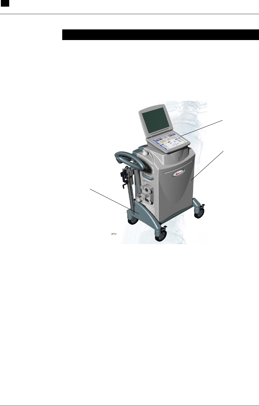
Overview
The RECOVER BP IABP/VAD System (RECOVER BP System) is a
versatile cardiac assist device that combines IABP and VAD support
capability within one Console (described in Section 4). This mobile
System uses a laptop-style interface.
Figure 1 RECOVER BP Console
Console
Cart
Laptop-style
Interface
The RECOVER BP IABP/VAD System 3
Disposables and Accessories
RECOVER BP IABP/VAD System – Operator’s Manual 3.3
Disposables and Accessories
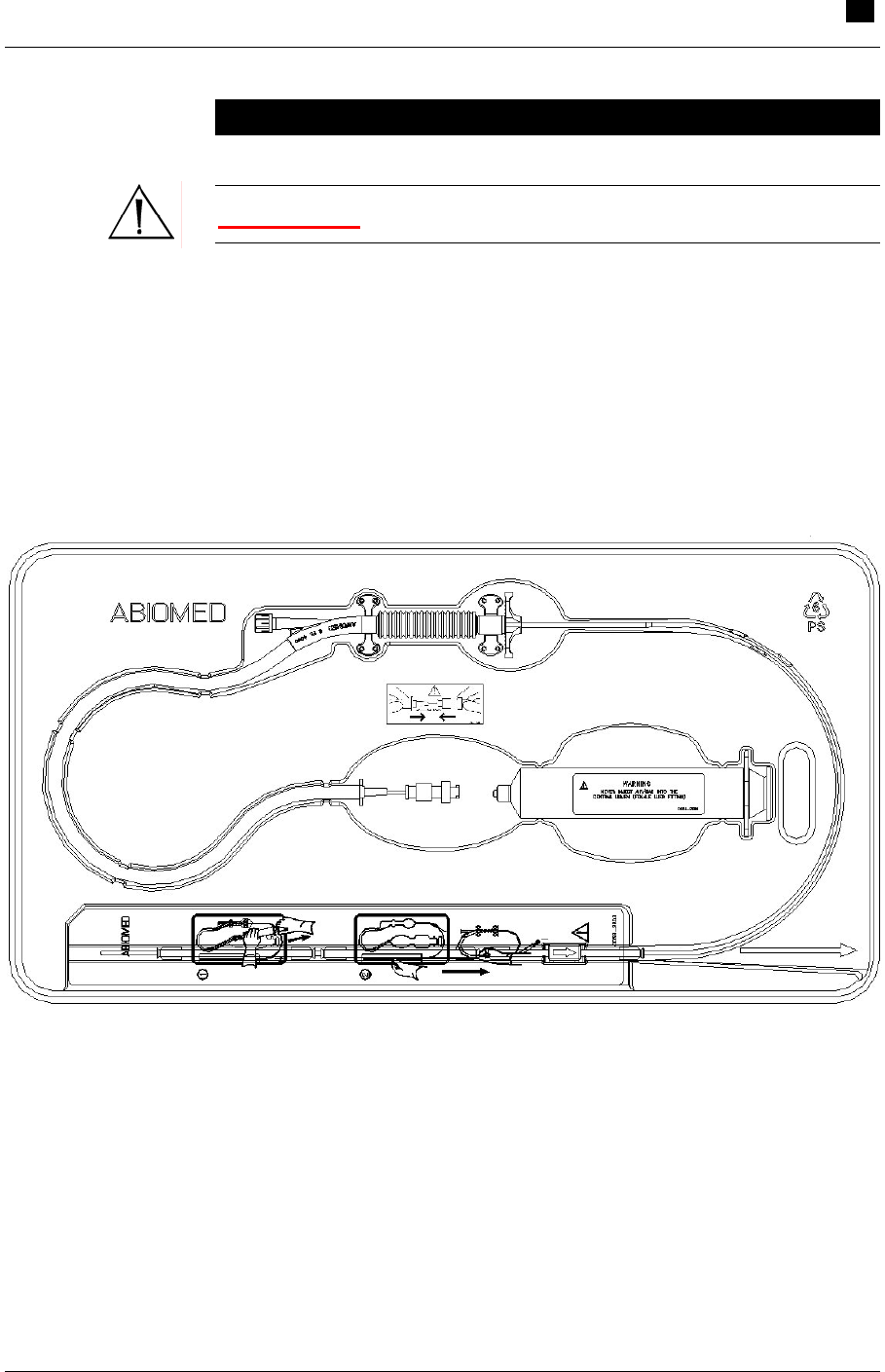
WARNING: Do NOT reuse single-use devices.
IABP
For IABP support (described in Section 6), the following items are
used with the RECOVER BP System:
• 8F 40 cc IAB Catheter Kit (see Figure 2)
Figure 2 IAB Catheter Kit
3 The RECOVER BP IABP/VAD System
Disposables and Accessories
3.4 RECOVER BP IABP/VAD System – Operator’s Manual
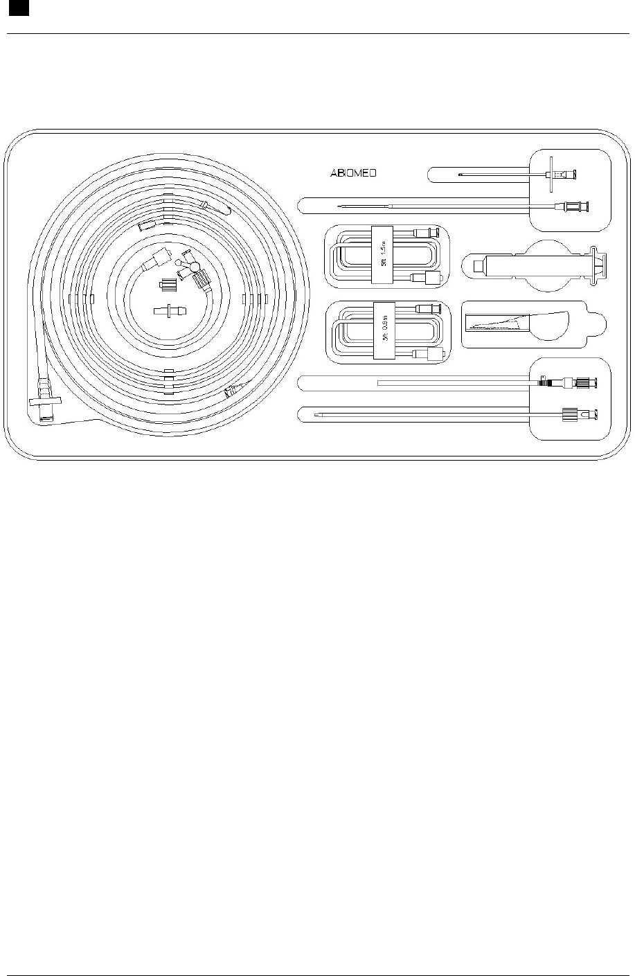
• IAB Insertion Kit (see Figure 3)
Figure 3 IAB Insertion Kit
• Patient Cable Set
• Helium Cylinder
• Chart Recorder Paper
• Adapter for Datascope® 8F (40 cc) IAB Catheter
VAD
For VAD support (described in Section 7), the following items are
used with the RECOVER BP System:
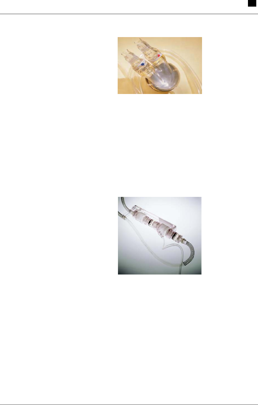
• AB5000™ Ventricle (Ventricle) – a pneumatically driven device
that provides pulsatile, hemodynamic support (see Figure 4). The
single-chamber Ventricle provides circulatory support in the
presence of left-, right-, or both-sided heart failure. It uses
vacuum assist technology to operate either horizontally or
vertically.
The RECOVER BP IABP/VAD System 3
Disposables and Accessories
RECOVER BP IABP/VAD System – Operator’s Manual 3.5
Figure 4 AB5000™ Ventricle
• BVS® Blood Pump (BVS Pump) – a pneumatically driven device
that provides pulsatile, hemodynamic support (see Figure 5). The
dual-chamber BVS Pump provides circulatory support in the
presence of left-, right-, or both-sided heart failure. It can operate
either vertically or horizontally and its atrial chamber fills
passively.
Figure 5 BVS® Blood Pump
• BVS® 5000 Atrial Cannula (32F, 36F, and 42F)
• BVS® 5000 Arterial Cannula (42F)
• BVS® Pump Mount Set (includes BVS® IV Pole Mount and
BVS® Bed Mount)
• Aircraft Mounting Plate

4.1
4 Using the RECOVER BP Console
Contents
Overview................................................................................................................4.2
Key Features .........................................................................................................4.3
Console Electrical Connections .............................................................................4.6
Keypad Layout.......................................................................................................4.7
Display Layout .......................................................................................................4.8
Menus.............................................................................................................4.8
Sample Screens ...........................................................................................4.11

4 Using the RECOVER BP Console
Overview
4.2 RECOVER BP IABP/VAD System – Operator’s Manual
Overview
The following pages present a general overview of Console features,
electrical connections, and interface layout.
For operating instructions, refer to IABP Support (Section 6) and
VAD Support (Section 7). These sections contain detailed instructions
and task-specific information.
Using the RECOVER BP Console 4
Key Features
RECOVER BP IABP/VAD System – Operator’s Manual 4.3
Key Features
The key mechanical features of the Console are shown in Figures 6, 7,
and 8. Tables 1, 2, and 3 describe the function of each feature.
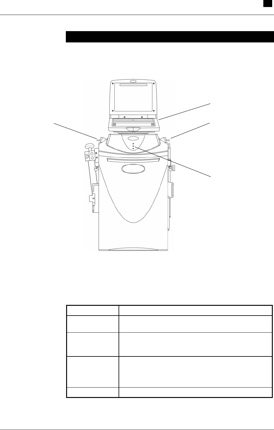
Figure 6 Console Features: Front View
Table 1 Console Feature Descriptions: Front View
Feature Description
Keypad and
Display Laptop-style user interface used to monitor and
control both VAD and IABP functions.
Left and Right
Driveline
Connectors
Connection points for driveline of an AB5000™
Ventricle or a BVS® Blood Pump.
Power Status
Indicators Lights that indicate Console battery status and
whether the Console is currently operating on AC or
battery power. See "Checking Console Power Status"
later in this section for further information.
Cooling Vents Allow cooling air to circulate through the Console.
Keypad and Display
Left Driveline Connecto
r
Right Driveline Connector
Power Status
Indicators
4 Using the RECOVER BP Console
Key Features
4.4 RECOVER BP IABP/VAD System – Operator’s Manual
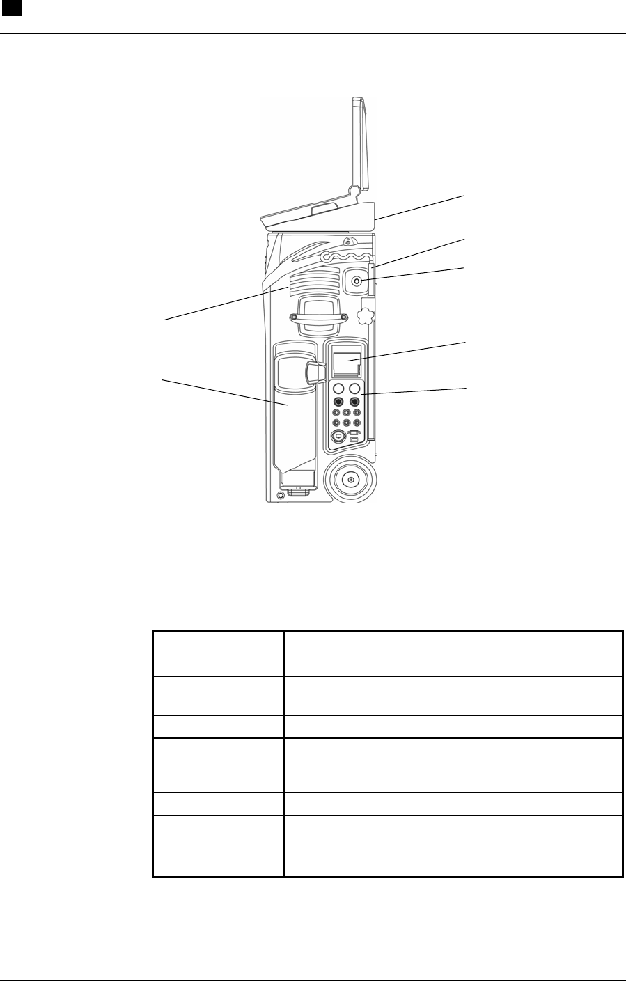
Figure 7 Console Features: Right-Side View
Table 2 Console Feature Descriptions: Right-Side View
Feature Description
Doppler Detects arterial blood flow.
IV Pole (for BVS®
Blood Pump only) Provides support for 2 BVS Blood Pumps.
IAB Connector Connection point for the IAB Catheter extender.
Chart Recorder Provides a printout of ECG, arterial pressure, and
balloon pressure waveforms. See "Using the
Printer" later in this section for further information.
Connection Panel Used to make electrical connections to the Console.
Helium Cylinder Storage tank for helium shuttle gas that is used to
inflate the balloon.
Cooling Vents Allow cooling air to circulate through the Console.
Cooling Vents
Helium Cylinde
r
Compartment
Doppler Compartment
IV Pole
Chart Recorder Cover
Connection Panel
IAB Connector
Using the RECOVER BP Console 4
Key Features
RECOVER BP IABP/VAD System – Operator’s Manual 4.5
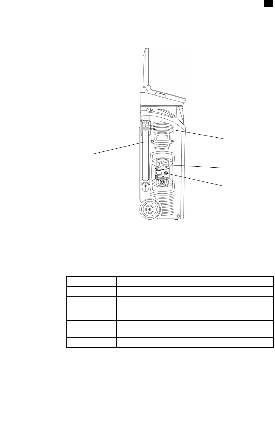
Figure 8 Console Features: Left-Side View
Table 3 Console Feature Descriptions: Left-Side View
Feature Description
Power Switch Switch to turn the Console ON or OFF.
Potential
Equalization
Terminal
Conductor for providing connection to the potential
equalization busbar of the installation.
Hand Pump Allows manual operation of an AB5000 Ventricle or a
BVS® Blood Pump.
Cooling Vents Allow cooling air to circulate through the Console.
Hand Pump
Cooling Vents
Power Switch
Potential
Equalization
Terminal
4 Using the RECOVER BP Console
Console Electrical Connections
4.6 RECOVER BP IABP/VAD System – Operator’s Manual
Console Electrical Connections
Electrical connections to the Console are made at the right-side panel.
The connections are shown in Figure 9 and briefly described in Table
4. Each connector is unique and keyed to ensure that connections are
made correctly.
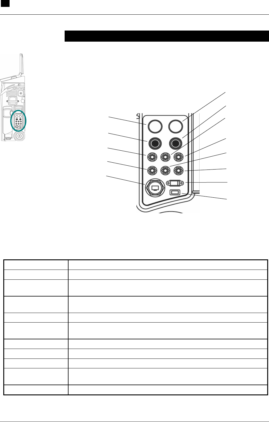
Figure 9 Console Electrical Connections
Table 4 Electrical Connection Descriptions
Connection Description
Arterial Pressure In Red 12-pin connector; connects to patient; 0–X VDC.
Arterial Pressure
High In ¼-inch phone jack; connects to an external patient monitor; can be used
by Console as a trigger; 0–5 VDC.
Remote Alarm ¼-inch phone jack; allows external monitoring of alarms; max. 40 VDC;
normally open contacts.
Arterial Pressure Out ¼-inch phone jack; connects to an external patient monitor; 0–5 VDC.
Balloon Assist Signal
Out ¼-inch phone jack; output timing signal for inflation; 0–5 VDC.
USB 1.1 or higher.
Ethernet RJ45 connector; 100/10BaseT.
ECG Out ¼-inch phone jack; connects to an external patient monitor; ± 2.5 VDC.
ECG High In ¼-inch phone jack; connects to an external patient monitor; can be used
by Console as a trigger; ± 2.5 VDC.
ECG In Green 12-pin connector; connects to patient; ± X mVDC; ± X mVAC.
ECG In
Not used
ECG Hi In
ECG Out
Arterial Pressure In
Not used
Arterial Pressure
High In
Remote Alarm
Arterial Pressure Out
Balloon Assist
Signal Out
Not used
USB
Ethernet
Using the RECOVER BP Console 4
Keypad Layout
RECOVER BP IABP/VAD System – Operator’s Manual 4.7
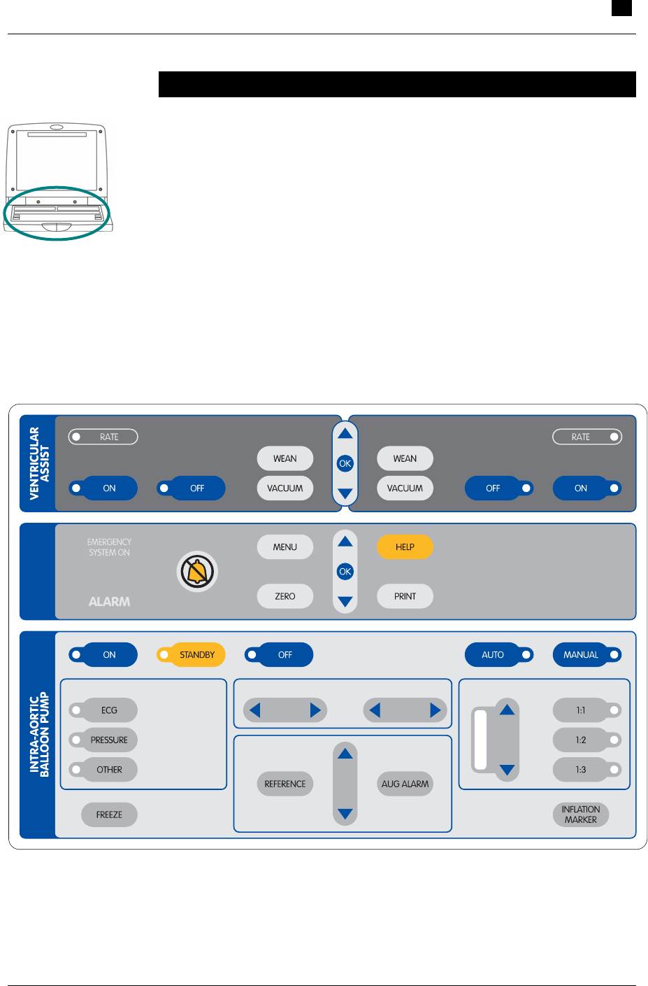
Keypad Layout
The keypad is used in conjunction with the display to control and
monitor the IABP and VAD functions of the Console.
The keypad is divided into three sections (see Figure 10):
• Intra-Aortic Balloon Pump – for performing IABP support (see
Section 6 for detailed descriptions of key functions).
• System – for handling tasks common to both IABP and VAD
support (see Section 5).
• Ventricular Assist – for performing VAD support (see Section 7).
SYSTEM
RIGHT
LEFT
FREQUENCY
AUG MENTATIONDEFLATIONINFLATIONTRIGGER SOURCE
Figure 10 Console Keypad
4 Using the RECOVER BP Console
Display Layout
4.8 RECOVER BP IABP/VAD System – Operator’s Manual
Display Layout
The Console display is a color LCD monitor that can be tilted to
achieve a comfortable viewing angle. You can swivel the keypad and
display unit in either direction, and the entire keypad/display unit
detaches for portable use while remaining connected to the Console
by a coiled cable.
The Console uses separate menus and screens for IABP and VAD
support.
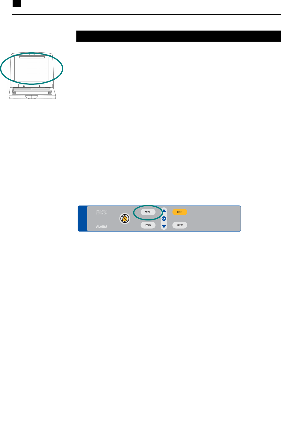
Menus
Pressing the MENU key in the System section of the keypad (see
Figure 11) displays the menu for the current function (either IABP or
VAD).
The complete menu structure is shown in Table 5.
SYSTEM
Figure 11 MENU Key

Using the RECOVER BP Console 4
Display Layout
RECOVER BP IABP/VAD System – Operator’s Manual 4.9
Table 5 Menu Structure
IABP Menu (see Section 6 for more information)
ECG Source (I, II, III, aVR, aVL, aVF, External)
ECG Gain (Auto, 0.5X, 0.75X, 1.0X, 1.25X, 1.5X, 2.0X, 3.0X)
AP Source (Direct, External)
Augmentation Alarm (Off, On)
System Menu
Print Menu
Waveforms (ECG/AP, ECG/BP, AP/BP, ECG,
AP, BP)
Speed (25 mm/sec, 50 mm/sec)
Strip Length (8 sec, 60 sec)
Auto Print (Off, 1 min, 5 min, 30 min, 1 hr, 2 hr)
Console Mode
Brightness Control (1–10)
Audio Level (High, Medium, Low)
Date & Time (MM/DD/YY)(HH:MM)
Language (English)
IP Address (nnn.nnn.nnn.nnn)
Field Service
Left Compressor Run-Time (nn hr)
Right Compressor Run-Time (nn hr)
Software Version Main Unit (A mnb)
Software Version Keypad (A mnb)
Close
(continued on next page)

4 Using the RECOVER BP Console
Display Layout
4.10 RECOVER BP IABP/VAD System – Operator’s Manual
Table 5 Menu Structure (continued)
VAD Menu (see Section 7 for more information)
Left Low Flow Alarm Threshold
Right Low Flow Alarm Threshold
BSA
System Menu
Print Menu
Waveforms (ECG/AP, ECG/BP, AP/BP, ECG,
AP, BP)
Speed (25 mm/sec, 50 mm/sec)
Strip Length (8 sec, 60 sec)
Auto Print (Off, 1 min, 5 min, 30 min, 1 hr, 2 hr)
Console Mode
Brightness Control (1–10)
Audio Level (High, Medium, Low)
Date & Time (MM/DD/YY)(HH:MM)
Language (English)
IP Address (nnn.nnn.nnn.nnn)
Field Service
Left Compressor Run-Time (nn hr)
Right Compressor Run-Time (nn hr)
Software Version Main Unit (A mnb)
Software Version Keypad (A mnb)
Close
Using the RECOVER BP Console 4
Display Layout
RECOVER BP IABP/VAD System – Operator’s Manual 4.11
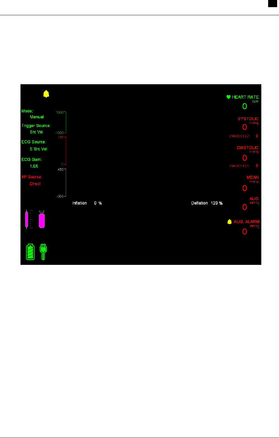
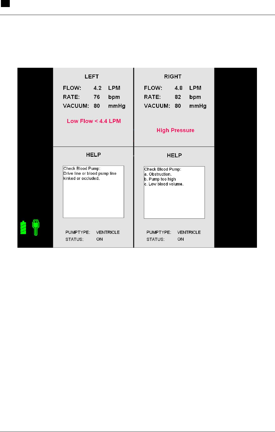
Sample Screens
Figure 12 (IABP) and Figure 13 (VAD) show samples of Console
screens.
Figure 12 Sample IABP Screen
4 Using the RECOVER BP Console
Display Layout
4.12 RECOVER BP IABP/VAD System – Operator’s Manual
Figure 13 Sample VAD Screen

5.1
5 System Status and Settings
Contents
Using the Interface.................................................................................................5.2
System Menu.........................................................................................................5.3
Checking Console Power Status............................................................................5.4
5 System Status and Settings
Using the Interface
5.2 RECOVER BP IABP/VAD System – Operator’s Manual
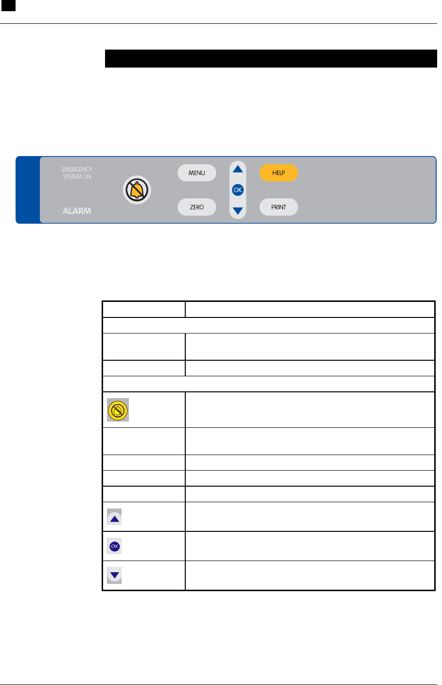
Using the Interface
The System section of the keypad (see Figure 14) is used for handling
tasks common to both IABP and VAD support. These indicators and
controls are described in Table 6.
SYSTEM
Figure 14 System Keypad
Table 6 System Keypad Functions
Feature Use
Indicator Lights
EMERGENCY
SYSTEM ON Red light flashes when the Emergency System is
operating. Refer to Section 8 for more information.
ALARM Red light flashes when any alarm is active.
Controls
Silences the alarm for approximately 1 minute.
MENU Displays the menu for the current function (IABP or
VAD).
ZERO Zeroes the arterial pressure (AP) transducer.
HELP Displays help text for handling VAD alarms.
PRINT Prints per the current Print settings.
Navigates through the selected function.
Selects the highlighted function.
Navigates through the selected function.
****[SYSTEM label]
System Status and Settings 5
System Menu
RECOVER BP IABP/VAD System – Operator’s Manual 5.3
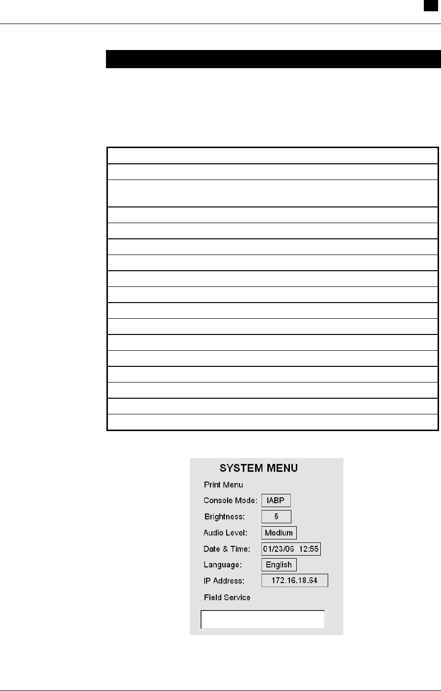
System Menu
The System menu (see Figure 15) is located on both the IABP menu
and the VAD menu. The menu structure is shown in Table 7.
Table 7 System Menu Structure
System Menu
Print Menu
Waveforms (ECG/AP, ECG/BP, AP/BP, ECG,
AP, BP)
Speed (25 mm/sec, 50 mm/sec)
Strip Length (8 sec, 60 sec)
Auto Print (Off, 1 min, 5 min, 30 min, 1 hr, 2 hr)
Console Mode (IABP, VAD)
Brightness Control (0–10)
Audio Level (High, Medium, Low)
Date & Time (MM/DD/YY)(HH:MM)
Language (English)
IP Address (nnn.nnn.nnn.nnn)
Field Service
Left Compressor Run-Time (nn hr)
Right Compressor Run-Time (nn hr)
Software Version Main Unit (A mnb)
Software Version Keypad (A mnb)
Figure 15 System Menu

5 System Status and Settings
Checking Console Power Status
5.4 RECOVER BP IABP/VAD System – Operator’s Manual
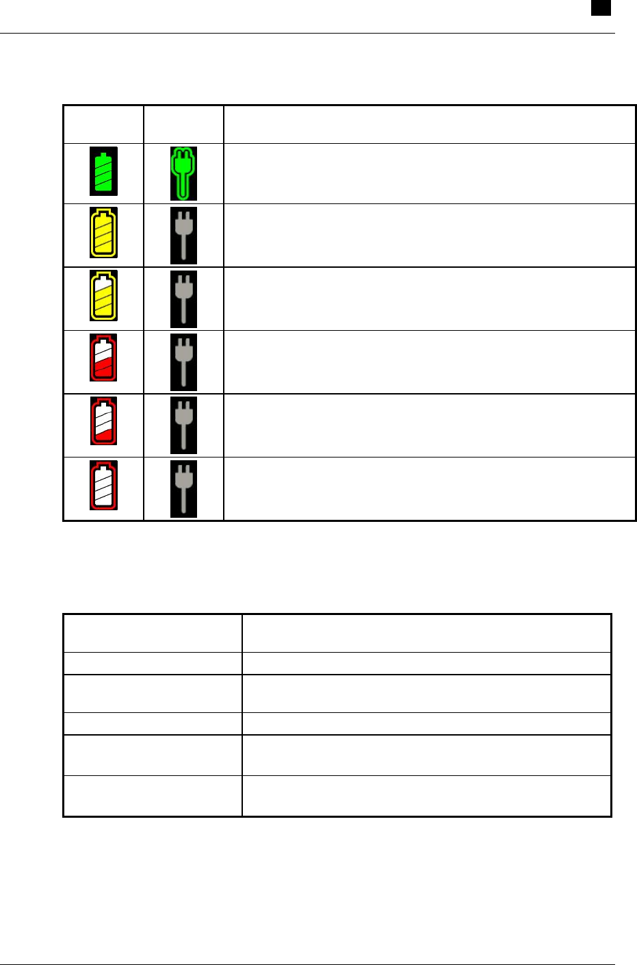
Checking Console Power Status
The Console runs on either AC power or its internal battery. It
continuously charges the battery, which requires approximately 16
hours to recharge after depletion, while it is plugged into AC power.
A fully charged battery will power the Console for one hour.
You can check on Console power status in two places:
• Two power status icons in the lower left corner of the IABP and
VAD screens.
• Three power status indicator lights on the front of the Console
just below the keypad ****[see Figure x].
Tables 8 and 9 describe the information provided in these two
locations.
System Status and Settings 5
Checking Console Power Status
RECOVER BP IABP/VAD System – Operator’s Manual 5.5
Table 8 Power Status Indicated by the IABP and VAD Screens
Battery
Icon AC Power
Icon Meaning
Console is using AC power (halo showing). Console Battery is
fully charged (all segments filled) but not in use (no halo).
Using Battery power. Battery is fully charged. AC power is
unplugged.
Using Battery power. Battery is about ¾ charged. AC power is
unplugged.
Using AC power. Battery is about ½ charged.
Using Battery power. Battery charge is low (icon flashes). AC
power is unplugged.
Using Battery power. Battery charge is critically low (icon
flashes). AC power is unplugged.
****[1 hour VAD, 2 hours IABP?]
Table 9 Power Status Shown by the Power Status Indicators
Power Status Indicator
and Condition Meaning
AC Power – green Console is using AC power.
Battery – amber Console is unplugged from AC power and has
automatically switched to battery power.
Battery – red Approximately 30 minutes of battery power remaining.
AC Power – green and
Charging – amber
Console is using AC power. Battery charge level is at
approximately 80%.
AC Power – green and
Battery – red
Possible battery fault.

6.1
6 IABP Support
Contents
Using the Interface.................................................................................................6.2
IABP Keypad ..................................................................................................6.2
IABP Screen ...................................................................................................6.4
Initial Setup ............................................................................................................6.6
Acquiring an Electrocardiograph (ECG) Waveform ........................................6.7
Acquiring an Arterial Pressure (AP) Waveform...............................................6.8
Connecting the IAB to the Console.................................................................6.9
Initiating Support..................................................................................................6.10
To Initiate Support in Auto Mode: .................................................................6.10
To Initiate Support in Manual Mode: .............................................................6.11
IABP Alarms ........................................................................................................6.19
Levels of Severity .........................................................................................6.19
Alarm Messages ...........................................................................................6.20
Alarm Tone Characteristics...........................................................................6.24
Alarm Silence Key ........................................................................................6.24
Weaning...............................................................................................................6.25
Using the Doppler ................................................................................................6.25
Using the Printer ..................................................................................................6.26
Replacing the Helium Cylinder.............................................................................6.27
6 IABP Support
Using the Interface
6.2 RECOVER BP IABP/VAD System – Operator’s Manual
Using the Interface
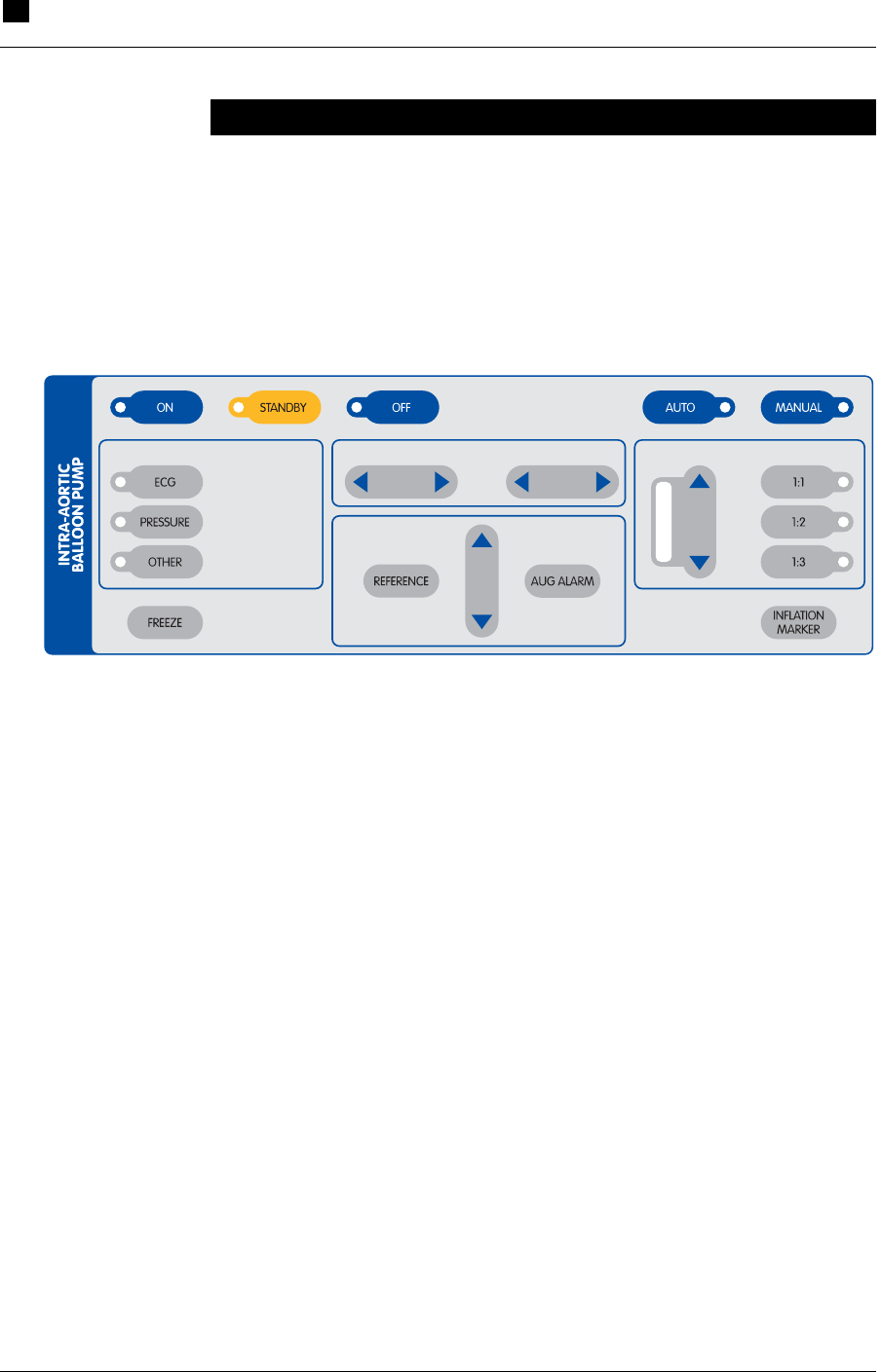
IABP Keypad
The IABP section of the keypad (see Figure 16) contains controls and
indicators for handling the tasks involved in IABP support. The
functions of these keys are described in Table 10.
FREQUENCY
AUG MENTATIONDEFLATIONINFLAT IONTRIGGER SOURCE
Figure 16 IABP Keypad

IABP Support 6
Using the Interface
RECOVER BP IABP/VAD System – Operator’s Manual 6.3
Table 10 IABP Keypad Functions
Feature Use
Control Keys
ON Purges the pneumatic system and starts pumping.
STANDBY Pauses pumping but keeps the Console ready to immediately resume
pumping. Pumping resumes when ON is pressed.
OFF Stops pumping when pressed twice within 13 seconds.
AUTO Automatically selects optimal ECG source, ECG gain, AP source,
trigger source, inflation timing, and deflation timing.
MANUAL Allows you to select ECG source, AP source, trigger source, inflation
timing, and deflation timing.
ECG Selects ECG signal as the trigger source.
PRESSURE Selects AP signal as the trigger source.
OTHER Allows you to select Apace, Vpace, or Internal as the trigger source.
FREEZE Freezes or unfreezes the display.
INFLATE In MANUAL mode, the left and right arrows adjust the inflation
interval. Inactive in AUTO mode.
DEFLATE In MANUAL mode, the left and right arrows adjust the deflation
interval. Inactive in AUTO mode.
REFERENCE Up and down arrows select the reference line.
AUG ALARM Up and down arrows set the augmentation alarm level.
AUG Up and down arrows set the augmentation level.
FREQ Selects assist frequency (1:1, 1:2, or 1:3).
INFLATION MARKER Turns inflation marker on or off.
Indicator Lights
ON Green light when ON is pressed.
STANDBY Amber light when STANDBY is pressed.
OFF Red light flashes when OFF is pressed once (pumping does not
stop). Light stays red when OFF is pressed twice within 13 seconds
(pumping stops).
AUTO Green light when AUTO is pressed.
MANUAL Amber light when MANUAL is pressed.
ECG Green light when ECG is selected as the trigger source.
PRESSURE Green light when AP is selected as the trigger source.
OTHER Green light when Apace, Vpace, or Internal is selected as the trigger
source.
AUGMENTATION Green light bar indicates augmentation level.
FREQ Green light indicates the selected assist frequency (1:1, 1:2, or 1:3).
****[INTRA-AORTIC BALLOON PUMP label]
6 IABP Support
Using the Interface
6.4 RECOVER BP IABP/VAD System – Operator’s Manual
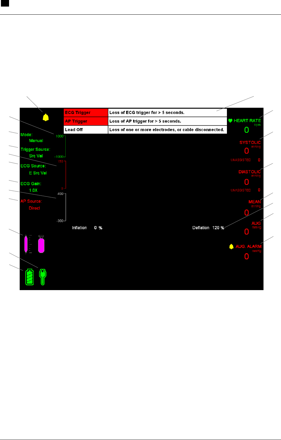
IABP Screen
The IABP screen (see Figure 17) enables you to monitor all aspects of
IABP operation. This screen also supplies patient information. These
display elements are described in Table 11.
Figure 17 IABP Screen
I
B
R
J
A
C
D
E
G
H
T
S
F
Q
O
N
P
M
L
K

IABP Support 6
Using the Interface
RECOVER BP IABP/VAD System – Operator’s Manual 6.5
Table 11 IABP Screen Descriptions
Item Display Element Description
A Alarm Messages Highest priority active alarms (3 maximum). Highest
priority alarm is at the top of the list. Refer to "IABP
Alarms" in this Section for more information.
B Heart rate Current heart rate in beats per minute (bpm); green text.
C Systolic pressure Red text; unassisted below in smaller text; mmHg.
D Diastolic pressure Red text; unassisted below in smaller text for 1:2 and 1:3
ratios only; mmHg.
E Mean Red text; mmHg.
F Inflation/Deflation timing White text (%); Inflation text not shown (located behind
Help text).
G Augmentation Red text; mmHg.
H Augmentation alarm Red text; gray icon is crossed out when alarm is silenced;
mmHg.
I Battery power icon Color of segments indicates battery status. Refer to
Table 8 in Section 5 for more information.
J AC power icon Color indicates AC power status. Refer to Table 8 in
Section 5 for more information.
K Helium supply icon Gray icon; also numeric value in pounds per square inch
(psi).
L AP source Red text.
Options: Direct, External.
M Balloon Pressure White trace.
N ECG gain Green text.
Options: Auto, 0.5x, 0.75x, 1.0x, 1.25x, 1.5x, 2.0x, 3.0x.
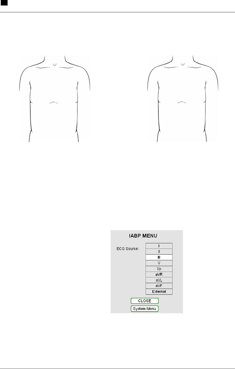
O ECG source Green text.
Options: I, II, III, V, aVR, aVL, aVF, External.
P AP Red trace (automatically scaled).
White inflation marker indicates inflation period.
Q Trigger source White text.
Options: ECG, AP, A-Pacer, V-Pacer, Internal.
R Operation mode White text; Auto or Manual.
S ECG Green trace; automatically scaled (optional gain levels
are available).
White inflation marker indicates inflation period.
Green vertical line indicates pacer trigger.
T Alarm indicator Indicates an alarm condition exists; icon is crossed out
when alarm is silenced.
6 IABP Support
Initial Setup
6.6 RECOVER BP IABP/VAD System – Operator’s Manual
Initial Setup
WARNING: Do NOT power the RECOVER BP System using
Multiple Portable Socket Outlets (MPSO) or an extension cord.
WARNING: Pumping an IAB that has a leak can result in: (1) a
blood clot in the IAB that may require surgical removal of the IAB,
and (2) air embolism.
WARNING: A patient monitor must be provided and used to
continuously monitor patient physiological pressure. Do NOT rely
solely on the System alarms to notify you of life-threatening
conditions.
1 Plug the Console power cord into an AC outlet.
2 Turn the Console ON using the AC power switch on the left side.
The Console goes through a Self-Test and is ready to use in
approximately 25 seconds. Verify that the audible alarm indicator
is operating properly by listening for the alarm tone during the
Self-Test.
NOTE: Upon power-up, the Console displays the same type of
screen (IABP or VAD) used at shutdown. If necessary, change to
IABP mode by pressing the MENU key and selecting System
Menu > Console Mode > IABP.
3 Open the cover of the helium cylinder compartment. Turn the
cylinder supply valve one-half turn counterclockwise to open the
valve. Make sure the helium cylinder pressure reading on the left
side of the display is at least ****[X] psi. Close the compartment
cover.

IABP Support 6
Initial Setup
RECOVER BP IABP/VAD System – Operator’s Manual 6.7
NOTE: If the helium cylinder pressure is less than ****[X] psi,
change the cylinder by following the steps in "Replacing the Helium
Cylinder" in this Section.
Acquiring an Electrocardiograph (ECG) Waveform
WARNING: Do NOT allow the conductive parts of electrodes and
associated connectors to contact any conductive parts and/or earth
ground.
Acquiring a high-quality electrocardiograph (ECG) waveform is an
important factor in achieving optimal triggering. An ECG waveform
can be obtained using either skin electrodes or the output of an
external monitor.
Using Skin Electrodes
1 Using the supplied patient ECG cable, connect each patient lead
wire to a skin electrode. Use only high-quality electrodes.
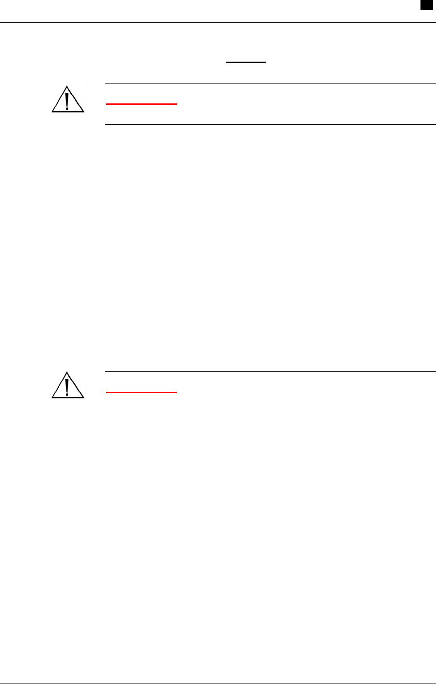
2 Attach electrodes to the patient as shown in the figures below.
Figure 18 Electrode Locations (AHA)
Figure 19 Electrode Locations (IEC)
RA
LA
V
RL
LL
RA
LA
C
RL
LL

6 IABP Support
Initial Setup
6.8 RECOVER BP IABP/VAD System – Operator’s Manual
3 Connect the patient ECG cable to the green ECG input connector
on the side panel of the Console.
4 Press the INFLATION MARKER key.
5 Check that the ECG waveform and heart rate are shown on the
display.
Using an External Monitor
1 Connect the interface cable to the ECG high-level patient monitor
input on the side panel.
2 Check that the heart rate is shown on the upper right side of the
display.
3 Press the INFLATION MARKER key.
4 Check that the ECG waveform and the heart rate are shown on
the display.
Acquiring an Arterial Pressure (AP) Waveform
An arterial pressure (AP) waveform can be obtained using either a
pressure transducer or the output of an external monitor.
Using a Pressure Transducer
NOTE: Refer to the Edwards Lifesciences Instructions for Use for
important information on using the TruWave Disposable Pressure
Transducer. Also refer to this document for volumetric displacement
information.
The inner lumen of the IAB is the preferred location for the placement
of a pressure transducer. This location results in the best waveform
for optimal triggering and timing. If this approach cannot be used, use
the radial artery per standard protocol.

IABP Support 6
Initial Setup
RECOVER BP IABP/VAD System – Operator’s Manual 6.9
1 Place a pressure catheter at the chosen location.
2 Connect the pressure catheter to the pressure transducer.
3 Zero the pressure transducer by pressing ZERO on the System
keypad.
4 Check that the peak and mean systolic/diastolic pressures are
displayed.
5 Check that the arterial pressure waveform is displayed after the
IAB is inserted.
****[mention heparin?]
Using an External Monitor
1 Connect the AP high-level input interface cable between the
external patient monitor and the high-level AP input on the side
panel. Make sure that ****[X] is selected on the display.
2 Check that the arterial pressure waveform is properly displayed.
Connecting the IAB to the Console
1 Remove the plug from the IAB extender input connector.
2 Connect the Console extension tubing to the IAB.
3 Connect the Console extension tubing to the Console IAB
connector.
4 Verify that the correct IAB size is shown on the left side of the
display.
5 Verify that the augmentation level is set at maximum.

6 IABP Support
Initiating Support
6.10 RECOVER BP IABP/VAD System – Operator’s Manual
Initiating Support
WARNING: Due to the potential for thrombus formation, an IAB
must NOT remain dormant.
You can initiate support in either Auto or Manual mode. The
appropriate mode depends on whether ease-of-use or flexibility is
needed.
In Auto mode (the default mode), the Console automatically chooses
the best option for the following settings:
• ECG source and ECG gain
• AP source
• Trigger source
• Inflation and deflation timing
The Console continuously monitors system parameters to adjust
settings as patient conditions change.
In Manual mode, you have the flexibility to choose from options for
the above settings.
To Initiate Support in Auto Mode:
1 Make sure “AUTO” is selected on the IABP keypad.
2 Press the ON key on the IABP keypad. The Console purges the
IAB Catheter, fills the Catheter with helium, and begins pumping
on the IAB.
NOTE: The Console automatically empties and refills the IAB every
two hours, after which support automatically resumes.
— This completes the steps for initiating support in Auto mode. —
IABP Support 6
Initiating Support
RECOVER BP IABP/VAD System – Operator’s Manual 6.11
To Initiate Support in Manual Mode:
WARNING: Due to the potential for thrombus formation, an IAB
must NOT remain dormant.
1 Select “Manual” on the IABP keypad.
2 Refer to the following text to choose the desired option for each
of the following settings:
• ECG source and ECG gain
• AP source
• Trigger source
• Inflation and deflation timing
Setting the ECG Source and ECG Gain
WARNING: Do NOT allow the conductive parts of electrodes and
associated connectors to contact any conductive parts and/or earth
ground.
Acquiring a high-quality electrocardiograph (ECG) waveform is an
important factor in achieving optimal triggering. An ECG waveform
can be obtained using either skin electrodes or the output of an
external monitor.
Using Skin Electrodes
1 Using the supplied patient ECG cable, connect each patient lead
wire to a skin electrode. Use only high-quality electrodes.
6 IABP Support
Initiating Support
6.12 RECOVER BP IABP/VAD System – Operator’s Manual
2 Attach electrodes to the patient as shown in the figures below.
Electrode Locations (AHA)
Electrode Locations (IEC)
3 Connect the patient ECG cable to the green ECG input connector
on the side panel of the Console.
4 Press the MENU key and select ECG Source from the IABP
menu. Select the desired ECG source (see Figure 20). The left
side of the display shows the selected source.
Figure 20 Selecting the ECG Source
RA
LA
V
RL
LL
RA
LA
C
RL
LL

IABP Support 6
Initiating Support
RECOVER BP IABP/VAD System – Operator’s Manual 6.13
5 Press MENU and select ECG Gain. Select the desired gain (see
Figure 21). The left side of the display shows the selected ECG
gain.
Figure 21 Selecting the ECG Gain
6 Check that the ECG waveform and heart rate are shown on the
display.
Using an External Monitor
1 Connect the interface cable to the ECG monitor input on the side
panel.
2 Press the MENU key and select ECG Source. Select the desired
ECG source. The left side of the display shows the selected
source.
3 Press MENU and select ECG Gain. Select the desired gain. The
left side of the display shows the selected ECG gain.
4 Check that the ECG waveform and heart rate are shown on the
display.
6 IABP Support
Initiating Support
6.14 RECOVER BP IABP/VAD System – Operator’s Manual
Setting the AP Source
Using a Pressure Transducer
NOTE: Refer to the Edwards Lifesciences Instructions for Use for
important information on using the TruWave Disposable Pressure
Transducer. Also refer to this document for volumetric displacement
information.
1 Connect the transducer cable to the red AP connector on the side
panel.
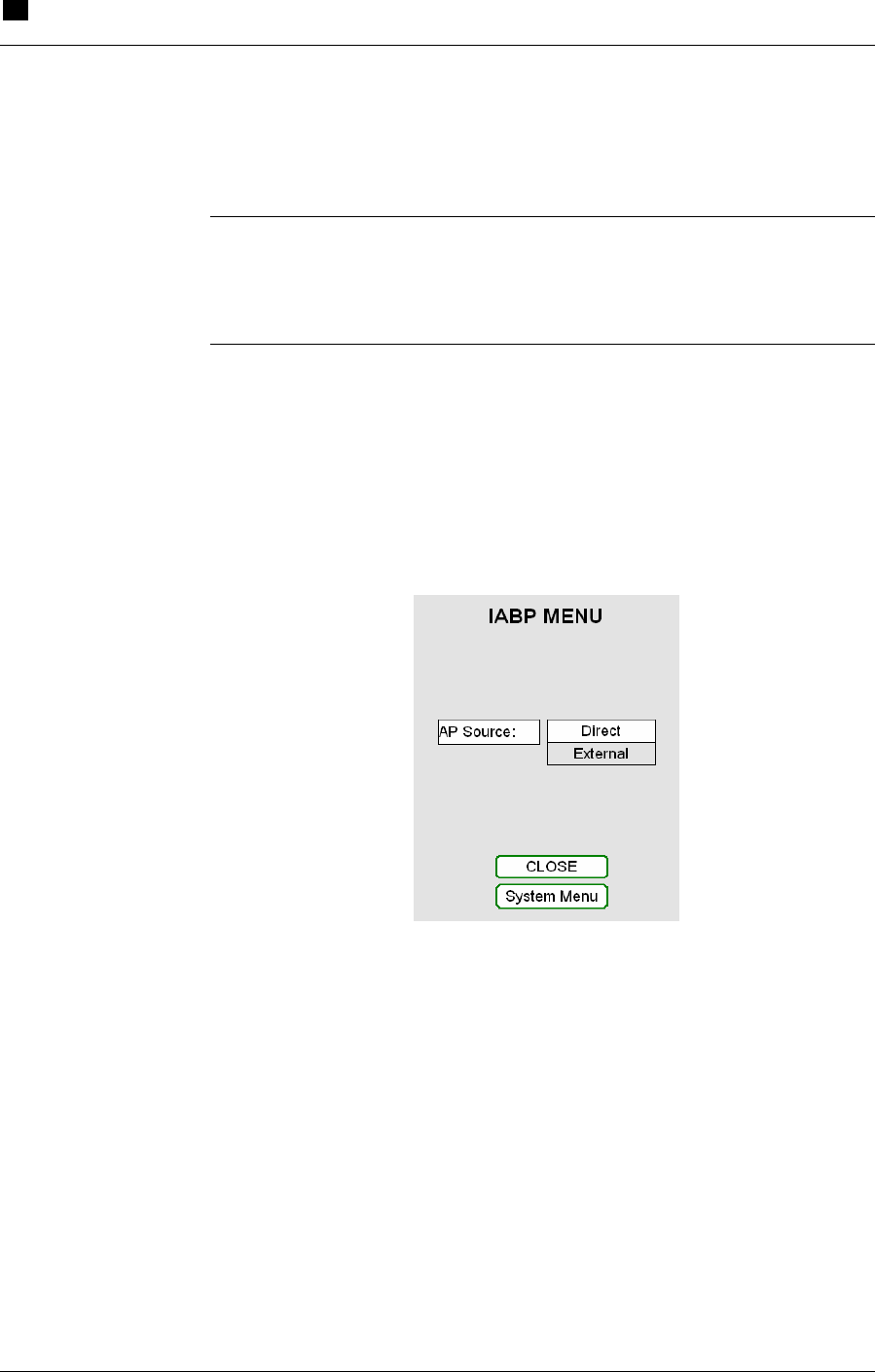
2 Press the MENU key and select AP Source > Direct (see Figure
22). The left side of the display shows the selected AP source.
****[delete AP Source white background]
Figure 22 Selecting the AP Source for a Transducer
3 Check that the arterial pressure waveform is displayed.
IABP Support 6
Initiating Support
RECOVER BP IABP/VAD System – Operator’s Manual 6.15
Using an External Monitor
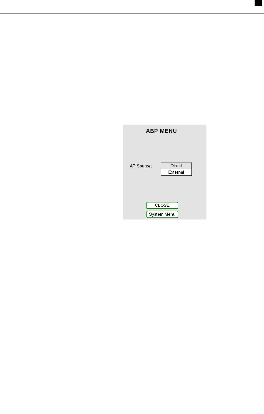
1 Connect the AP high-level input interface cable between the
external patient monitor and the high-level AP input on the side
panel. Make sure that ****[X] is selected on the display.
2 Press the MENU key and select AP Source > External (see
Figure 23). The left side of the display shows the selected AP
source.
Figure 23 Selecting the AP Source for an External Monitor
3 Check that the arterial pressure waveform is properly displayed.
Selecting the Trigger Source
ECG
Using this setting, the Console triggers on the QRS and ignores
pacemaker pulses. Select this option under TRIGGER SOURCE on
the keypad.
6 IABP Support
Initiating Support
6.16 RECOVER BP IABP/VAD System – Operator’s Manual
Pressure
WARNING: When pressure triggering is used, adjust deflation to
be complete at the upstroke of systole.
WARNING: Do NOT use pressure triggering while arrhythmia is
present.
The Console triggers on the arterial pressure waveform. Select this
option under TRIGGER SOURCE on the keypad.
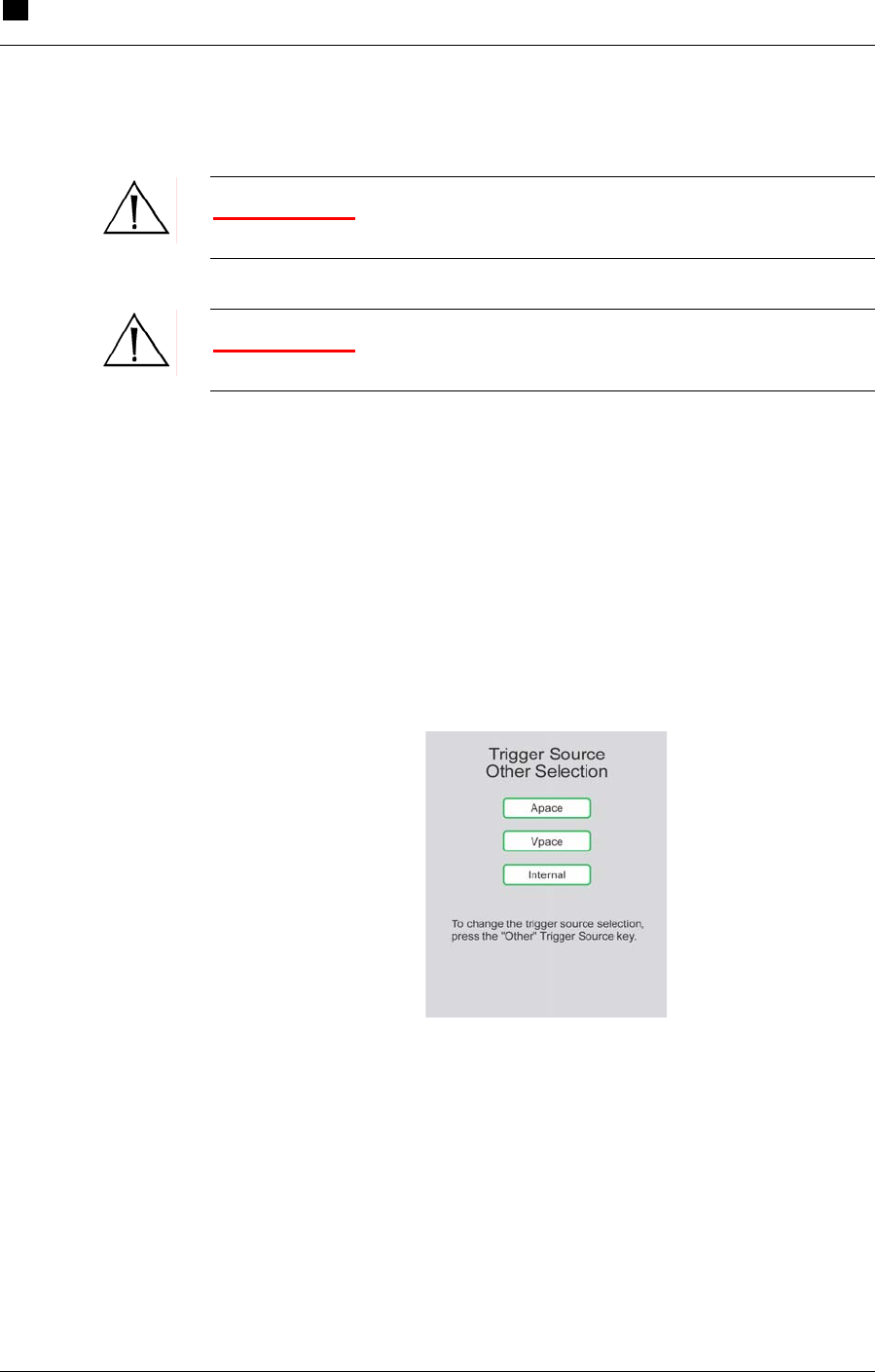
Apace
The Console triggers on a pacer. Select this option by choosing Other
(under TRIGGER SOURCE) and then selecting Apace from the
Trigger Source Other Selection menu.
Figure 24 Selecting Apace as the Trigger Source
Make sure that the pacemaker pulses are being detected by ****[X].
The Apace signal must have an amplitude of ****[X] µV minimum
and a pulse duration of ****[X] ms minimum.
IABP Support 6
Initiating Support
RECOVER BP IABP/VAD System – Operator’s Manual 6.17
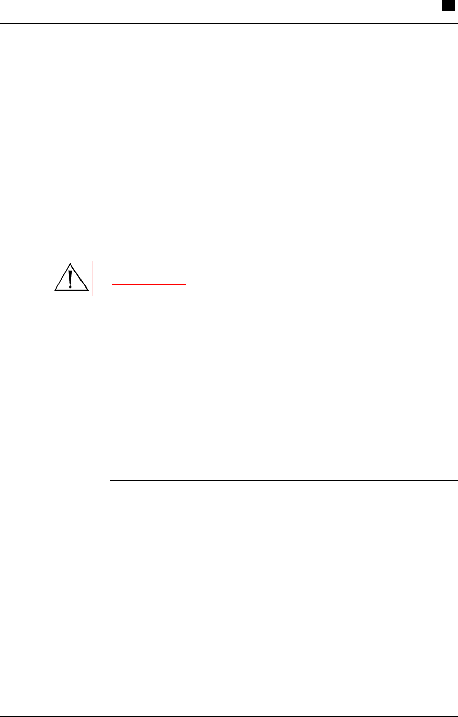
Vpace
The Console triggers on the ventricular waveform of the pacer. You
can choose this option by selecting Other (under TRIGGER
SOURCE) and then selecting Vpace from the Trigger Source Other
Selection menu.
Make sure that the pacemaker pulses are being detected by ****[X].
The Vpace signal must have an amplitude of ****[X] µV minimum
and a pulse width of ****[X] ms minimum.
Internal
WARNING: Do NOT use Internal trigger source while the patient
is producing cardiac output.
Use this setting when there is no cardiac cycle. Choose this option by
pressing Other (under TRIGGER SOURCE) and selecting Internal.
If an ECG signal is detected while the internal trigger is in use, the
system sounds an alarm, at which time the trigger source should be
changed to ECG for optimal triggering.
NOTE: Check that the selected trigger source is shown on the left
side of the display.

6 IABP Support
Initiating Support
6.18 RECOVER BP IABP/VAD System – Operator’s Manual
Setting Inflation and Deflation Timing
WARNING: If the heart rate varies by more than 10 beats per
minute (bpm) within ****[X] seconds, evaluate inflation and deflation
timing and make adjustments if necessary.
1 Press the ON key on the IABP keypad. The Console purges the
IAB Catheter, fills the Catheter with helium, and begins pumping
on the IAB.
2 ****[Initial timing procedure and graphic]
NOTE: The Console automatically empties and refills the IAB every
two hours, after which support automatically resumes.
Inflation Timing
Use the left and right INFLATE keys to adjust the inflation timing
until the highlighted segment of the arterial pressure trace begins at
the dicrotic notch.
****[Timing graphic]
Deflation Timing
Use the left and right DEFLATE keys to adjust the deflation timing
until the end of the highlighted segment of the arterial pressure trace
is just prior to ventricular ejection.
****[Timing graphic]
— This completes the steps for initiating support in Manual
mode. —
IABP Support 6
IABP Alarms
RECOVER BP IABP/VAD System – Operator’s Manual 6.19
IABP Alarms
The Console monitors various functions to determine whether its
operating parameters are within expected limits. When a parameter
goes outside of its limits, the Console displays an alarm message and
sounds an alarm tone. The severity of the alarm is indicated by the
color of the alarm message and by the characteristics of the alarm
tone.
Levels of Severity
Alarms are divided into three levels of severity:
• Life-Threatening – Red
• Serious – Yellow
• Advisory – White
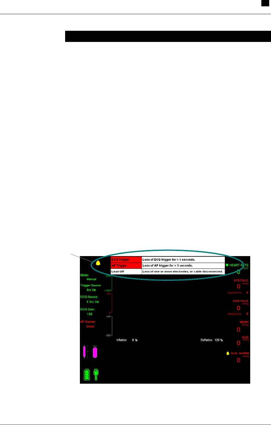
A maximum of three alarms are displayed on the IABP screen (see
Figure 27). Alarms are listed in order of importance, with the highest
priority alarm at the top of the list. Each alarm is accompanied by
descriptive text to help you with resolving the alarm.
Figure 25 Alarm Messages on the IABP Screen
Alarm Messages

6 IABP Support
IABP Alarms
6.20 RECOVER BP IABP/VAD System – Operator’s Manual
Alarm Messages
Table 12 shows all IABP alarm messages.
Table 12 IABP Red Alarm Messages
RED ALARMS Category: Life-Threatening
Alarm Message
Possible Cause
Action
SYSTEM FAILURE
Change to Backup Console
• System failure.
• Keypad not
working/connected.
1. Change to backup
Console.
2. Check keypad
connection.
3. Call for service.
PRESSURE LOW
Leak in Catheter / Driveline
• Balloon rupture.
• Loose driveline
connection.
• Fluid in driveline.
1. Inspect Catheter
for blood or fluid.
2. Inspect
Catheter/driveline
connection.
PRESSURE LOW
Fill Failure
• Loose driveline
connection.
• Possible System
failure.
1. Inspect
Catheter/driveline
connection.
2. Change to backup
Console.
PRESSURE LOW
Disconnected Driveline
• Disconnected
driveline.
Inspect
Catheter/driveline
connection.
PRESSURE HIGH
Catheter / Driveline Occlusion
• Kink in Catheter or
driveline.
• Balloon failed to
unwrap.
1. Assess patient
position.
2. Inspect Catheter
and driveline for
kinks.
3. Inspect balloon for
unwrap failure.

IABP Support 6
IABP Alarms
RECOVER BP IABP/VAD System – Operator’s Manual 6.21
Table 12 IABP Red Alarms (continued)
RED ALARMS Category: Life-Threatening
Alarm Message
Possible Cause
Action
TRIGGER
No Trigger Source
• Unable to detect
ECG or AP signal.
1. Check ECG
leads/connection.
2. Check AP
transducer/connection.
TRIGGER
No ECG Signal Detected
• Unable to detect
ECG signal.
• Noise on ECG signal.
1. Check ECG
leads/connection.
2. Limit movement of ECG
cables.
3. Switch to Auto or AP
mode.
TRIGGER
No AP Signal Detected
• Unable to detect AP
signal.
• Low pulse pressure.
1. Check AP
transducer/connection.
2. Check position of AP
transducer valve.
3. Flush and re-zero AP
transducer.
4. Change to Auto mode or
ECG trigger source.
TRIGGER
No Pacer Signal Detected
• Intermittent pacing.
• No pacer signal
spike.
• Unable to detect
ECG signal.
1. Change to Auto mode.
2. Check ECG
leads/connection.

6 IABP Support
IABP Alarms
6.22 RECOVER BP IABP/VAD System – Operator’s Manual
Table 13 IABP Yellow Alarm Messages
YELLOW ALARMS Category: Serious
Alarm Message
Possible Cause
Action
TRIGGER
Erratic Trigger Source
• Noise on ECG or AP
signal.
1. Check ECG
leads/connection.
2. Limit movement of
ECG leads.
3. Change to Auto or
AP mode.
TRIGGER
ECG Detected
• ECG activity
detected.
Change to Auto mode or
ECG trigger source.
AUGMENTATION
Below Set-Limit
• Patient
hemodynamics.
• Timing.
• Augmentation alarm
limit set too high.
1. Assess the patient.
2. Adjust timing.
3. Adjust augmentation
alarm limit.
STANDBY
Prolonged Time
• Console in Standby
for more than 3
minutes.
1. Resolve active
alarms.
2. If appropriate,
resume pumping.
HELIUM SUPPLY
Empty
• Helium cylinder valve
closed.
• Helium cylinder
empty.
• Helium supply leak.
1. Open helium cylinder
valve.
2. Replace helium
cylinder.
3. Check helium supply
connection.

IABP Support 6
IABP Alarms
RECOVER BP IABP/VAD System – Operator’s Manual 6.23
Table 14 IABP White Alarm Messages
WHITE ALARMS Category: Advisory
Alarm Message
Possible Cause
Action
LEAD OFF
ECG Electrode
• ECG lead off.
1. Check ECG leads.
2. Limit movement of
ECG leads.
HELIUM SUPPLY
Low
• Low helium cylinder
pressure.
Replace helium
cylinder.
SYSTEM
Chart Recorder
• Out of paper.
• Door open.
1. Check paper.
2. Close door.
3. Call for service.
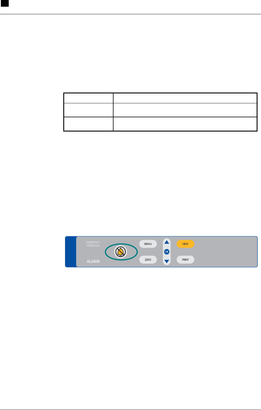
6 IABP Support
IABP Alarms
6.24 RECOVER BP IABP/VAD System – Operator’s Manual
Alarm Tone Characteristics
The Console signals life-threatening and serious alarms using unique
sounds (see Table 15).
Table 15 Alarm Tone Characteristics
Severity Level Description of Alarm Tone
Life-Threatening Continuous beeps (4 times per second)
Serious 4 beeps within 1 second; repeats every 5 seconds
Alarm Silence Key
Pressing the alarm silence key on the System keypad (see Figure 26)
silences the alarm tone for approximately 1 minute. The alarm sounds
again if the alarm condition is still present after 1 minute.
The alarm sounds immediately, whether the alarm silence key has
been pressed or not, if a new alarm condition occurs.
SYSTEM
Figure 26 Alarm Silence Key

IABP Support 6
Using the Doppler
RECOVER BP VAD/IABP System – Operator’s Manual 6.25
Weaning
The patient should be weaned from IABP support per hospital
protocol.
Using the Doppler
The Doppler unit used with the RECOVER BP System is the Koven
EchoSounder™ ES-101EX. It is stored in a compartment at the back
of the keypad base.
To use the Doppler, follow these steps:
1 Open the compartment door and lift out the Doppler unit, which
is tethered to the Console.
2 Turn the unit ON by pressing the power/freeze button.
3 Apply ultrasonic gel to the patient's skin or to the transducer.
4 Place the transducer on the artery to be checked. Move the unit
slowly to find the location at which the unit generates the loudest
sound. The optimal probe angle is approximately 60 degrees.
5 Adjust the sound volume by pressing the volume/mode button for
less than 1 second.
NOTE: Refer to the Koven EchoSounder™ ES-101EX Instructions
for Use for more information on the Doppler unit.

6 IABP Support
Using the Printer
6.26 RECOVER BP IABP/VAD System – Operator’s Manual
Using the Printer
You can access various printing options by pressing the MENU key in
the System section of the keypad and selecting System Menu > Print
Menu. The following options are available:
• Waveforms – ECG/AP, ECG/BP, AP/BP, ECG, AP, BP
• Speed – 25 mm/sec, 50 mm/sec
• Strip length – 8 sec, 60 sec
• Auto Print – Off, 1 min, 5 min, 30 min, 1 hr, 2 hr
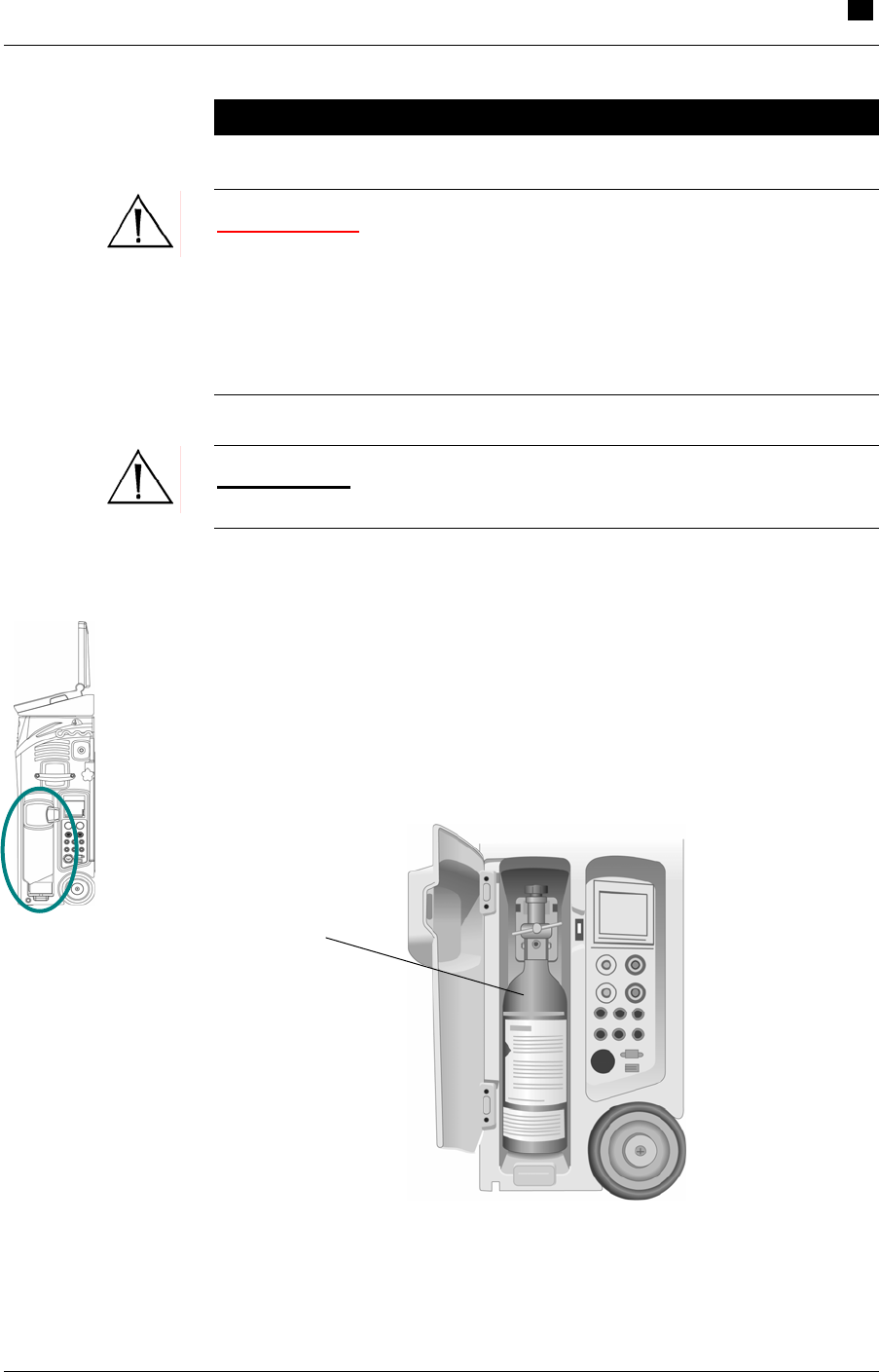
IABP Support 6
Replacing the Helium Cylinder
RECOVER BP VAD/IABP System – Operator’s Manual 6.27
Replacing the Helium Cylinder
WARNING: Be sure to follow all warnings and cautions on the
high-pressure gas (helium) cylinder. Observe all Department of
Transportation (DOT) and International Air Transport Association
(IATA) regulations for Dangerous Goods/Hazardous Materials when
transporting a Console containing a helium cylinder. Only personnel
trained in the handling of high-pressure gas cylinders should install or
replace the helium cylinder.
CAUTION: Close the helium cylinder supply valve when the
Console is not in use.
When either the HELIUM SUPPLY EMPTY or HELIUM SUPPLY
LOW alarm message is displayed, change the helium cylinder by
following the steps below:
1 Open the helium cylinder compartment (see Figure 27).
Figure 27 Helium Cylinder Compartment
Helium Cylinde
r
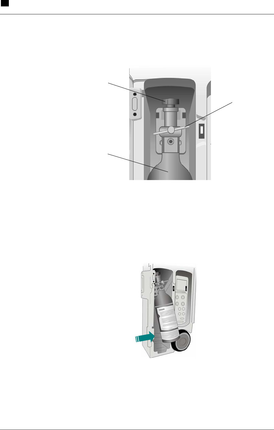
6 IABP Support
Replacing the Helium Cylinder
6.28 RECOVER BP IABP/VAD System – Operator’s Manual
2 Turn the supply valve handle fully clockwise to close the cylinder
valve (see Figure 28).
Figure 28 Helium Cylinder Components
3 Tilt the cylinder at a slight angle (see Figure 29). Support the
cylinder and slowly turn the T-handle clamp (see Figure 28)
counterclockwise to loosen it.
Figure 29 Tilting the Helium Cylinder
Supply Valve Handle
T-Handle Clamp
Helium Cylinde
r

IABP Support 6
Replacing the Helium Cylinder
RECOVER BP VAD/IABP System – Operator’s Manual 6.29
4 Slowly remove the cylinder. Remove the sealing washer, inspect
the washer for damage (replace it with a new one if necessary),
and place it back on the regulator.
5 Install the new cylinder and hand-tighten the T-handle clamp.
Gently push the cylinder back into the compartment.
6 Open the supply valve by turning the handle counterclockwise
one-half turn.
7 Close the cylinder compartment.

7.1
7 VAD Support
Contents
Using the Interface.................................................................................................7.2
VAD Keypad ...................................................................................................7.2
VAD Screen....................................................................................................7.3
Using the AB5000™ Ventricle.................................................................................7.4
Console Preparation .......................................................................................7.4
AB5000 Ventricle Preparation.........................................................................7.4
Recommended Cannulation Method ..............................................................7.5
Pump Type Verification...................................................................................7.5
Initiating Support.............................................................................................7.5
Optimizing AB5000 Ventricle Filling................................................................7.5
Adjusting Vacuum Level .................................................................................7.6
To Stop Pumping ............................................................................................7.8
Weaning..........................................................................................................7.8
Adjusting the Low Flow Alarm Level ...............................................................7.8
Remote Alarm Output .....................................................................................7.9
Preparing the Console for Intrahospital Transport ..........................................7.9
Using the BVS® Blood Pump ...............................................................................7.10
Console Preparation .....................................................................................7.10
BVS Pump Preparation.................................................................................7.10
Recommended Cannulation Method ............................................................7.10
Pump Type Verification.................................................................................7.10
Initiating Support...........................................................................................7.10
Optimizing BVS Pump Filling........................................................................7.11
Mounting the BVS Pump to the Accessory Mounts ......................................7.11
Adjusting the Low Flow Alarm Level .............................................................7.14
To Stop Pumping ..........................................................................................7.14
Weaning........................................................................................................7.14
Remote Alarm Output ...................................................................................7.14
Preparing the Console for Intrahospital Transport ........................................7.15
VAD Alarms .........................................................................................................7.16
Levels of Severity .........................................................................................7.16
VAD Alarm Messages and Help Text ...........................................................7.17
Using the Hand Pump..........................................................................................7.19
Transferring to the Hand Pump.....................................................................7.19
Transferring from the Hand Pump to a Backup Console ..............................7.19
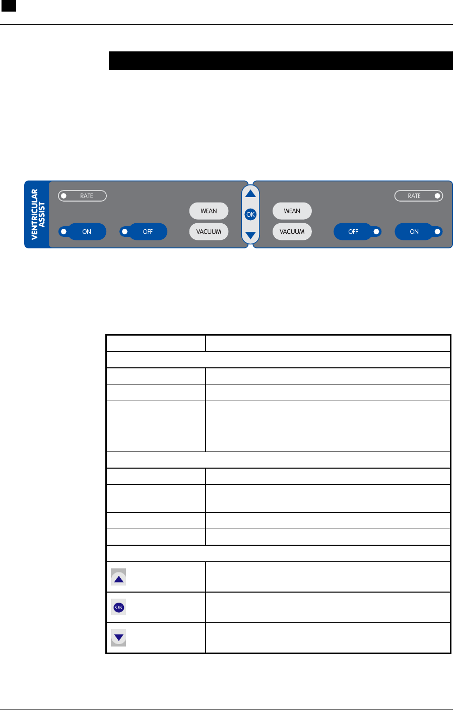
7 VAD Support
Using the Interface
7.2 RECOVER BP IABP/VAD System – Operator’s Manual
Using the Interface
VAD Keypad
The elements of the Ventricular Assist section of the keypad (see
Figure 30) are described in Table 16.
RIGHT
LEFT
Figure 30 VAD Keypad
Table 16 VAD Keypad Functions
Feature Use
Indicator Lights (LEFT and RIGHT)
RATE Amber light flashes with each beat.
ON Green light when ON is pressed.
OFF Red light flashes when OFF is pressed once
(pumping is not stopped). Light stays red when OFF
is pressed twice within 13 seconds (pumping is
stopped).
Controls (LEFT and RIGHT)
ON Starts pumping.
OFF Stops pumping when pressed twice within 13
seconds.
WEAN Displays weaning menu.
VACUUM Displays vacuum menu.
Navigation Controls
Navigates through the selected function.
Selects the highlighted function.
Navigates through the selected function.
****[VENTRICULAR ASSIST label]
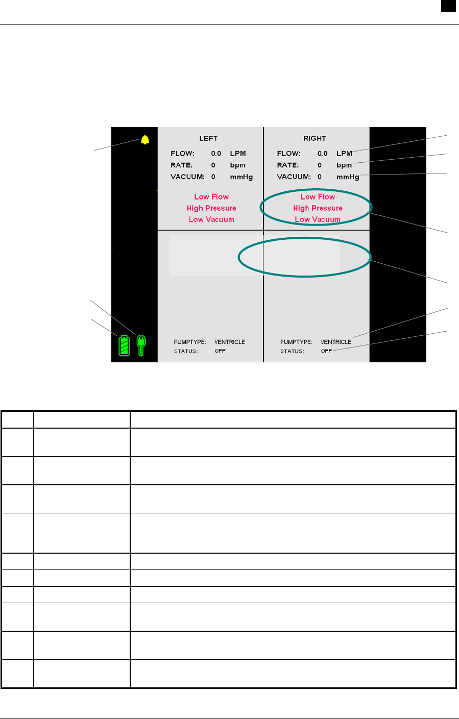
VAD Support 7
Using the Interface
RECOVER BP IABP/VAD System – Operator’s Manual 7.3
VAD Screen
The VAD screen (see Figure 31) allows you to monitor all aspects of
VAD operation. These display elements are described in Table 17.
Figure 31 VAD Screen
Table 17 VAD Screen Descriptions
Item Display Element Description
A Flow Black text in normal operation; green text in wean mode. Blood flow
rate in liters per minute (L/min).
B Rate Black text in normal operation; green text in wean mode. Beat rate in
beats per minute (bpm).
C Vacuum Black text in normal operation; green text in wean mode. User-
adjustable vacuum level in millimeters of mercury (mmHg).
D Alarm Messages Red text; highest priority active alarms (3 maximum for each side).
Highest priority alarm is at the top of the list. For more information,
refer to "VAD Alarms" in this Section.
E Help text Lists action(s) to take to resolve an alarm.
F Blood pump type BVS® Blood Pump or AB5000™ Ventricle.
G Blood pump status Indicates whether blood pump is ON or OFF.
H Battery power icon Color of segments indicates battery status. Refer to Table 8 in
Section 5 for more information.
I AC power icon Color indicates AC power status. Refer to Table 8 in Section 5 for
more information.
J Alarm icon Indicates an alarm condition exists; icon is crossed out when alarm is
silenced.
Check Blood Pump:
-Disconnect or leak
in drive line.
Check Blood Pump:
-Drive line or blood
pump lines kinked
or occluded.
H
A
D
E
I F
G
B
C
J
7 VAD Support
Using the AB5000™ Ventricle
7.4 RECOVER BP IABP/VAD System – Operator’s Manual
The RECOVER BP System provides VAD support capability using
either the AB5000™ Ventricle (Ventricle) or the BVS® Blood Pump
(BVS Pump).
The following sections describe the procedures for using each blood
pump type.
WARNING: A patient monitor must be provided and used to
continuously monitor patient physiological pressure. Do NOT rely
solely on the System alarms to notify you of life-threatening
conditions.
Using the AB5000™ Ventricle
WARNING: Do NOT power the RECOVER BP System using
Multiple Portable Socket Outlets (MPSO) or an extension cord.
Console Preparation
1 Plug the Console power cord into an AC outlet.
2 Turn the Console ON using the AC power switch on the left side.
The Console goes through a Self-Test and is ready to use in
approximately 25 seconds. Verify that the audible alarm indicator
is operating properly by listening for the alarm tone during the
Self-Test.
NOTE: Upon power-up, the Console displays the same type of
screen (IABP or VAD) used at shutdown. If necessary, change to
VAD mode by pressing the MENU key and selecting System
Menu > Console Mode > VAD.
AB5000 Ventricle Preparation
Refer to the AB5000™ Ventricle Instructions for Use (0055-9001) and
AB5000™ Ventricle Training Guide (0055-9002).

VAD Support 7
Using the AB5000™ Ventricle
RECOVER BP VAD/IABP System – Operator’s Manual 7.5
Recommended Cannulation Method
Refer to the Cannula Instructions for Use (0506-9110).
Pump Type Verification
Be sure that “Ventricle” is displayed as the pump type.
Initiating Support
1 Initiate support as described in the AB5000 Ventricle Instructions
for Use and the AB5000 Ventricle Training Guide.
2 Begin pumping by pressing the ON key for the appropriate side
(Left or Right). If both sides are being supported, press the Left
ON key first.
Optimizing AB5000 Ventricle Filling
When the Console is operating in normal (full flow) mode, flow rate
should be greater than 2 L/min and typically ranges from 3 to
6 L/min.
To optimize blood flow, be sure that the patient is appropriately
hydrated, with filling pressures within normal ranges. If the patient is
hypovolemic, administer fluids according to hospital protocol.
The Ventricle is filled via vacuum assist. However, avoid raising the
Ventricle above the heart to view it, because this could result in lower
flow.

7 VAD Support
Using the AB5000™ Ventricle
7.6 RECOVER BP IABP/VAD System – Operator’s Manual
Adjusting Vacuum Level
Overview
The Console applies a default level of 100 mmHg (1.9 psi) of vacuum
during diastole unless the vacuum level has been adjusted. You can
adjust the vacuum level from 35 to 100 mmHg (0.7 to 1.9 psi) (in 5
mmHg (0.1 psi) steps) whether pumping is ON or OFF.
Reducing the vacuum level to 35 mmHg (0.7 psi) reduces the flow
rate by as much as 2 L/min from the level achieved at 100 mmHg (1.9
psi). Reducing the vacuum level also changes the vacuum alarm
limits.
Flow rate reduction for weaning can be performed using the weaning
controls alone, by reducing the vacuum level alone, or by using both
means of flow reduction simultaneously.
If an increase in flow rate is desired, increasing the vacuum level
increases the flow rate, provided that there are no conditions limiting
the flow through the device such as:
• Obstructions in the inflow cannula, outflow cannula, or driveline.
• Inadequate blood volume.
• Mispositioning of the AB5000 Ventricle.
• Disconnection or leak in the driveline.
Increasing the vacuum level to increase the flow rate can be used in
response to activation of the low flow alarm during normal operation,
or during weaning operation when the target flow level cannot be
maintained at a reduced level of vacuum.
NOTE: If an inadvertent key stroke is made, allow the Console
display to stabilize for about 5 seconds before proceeding. The
display may take several seconds to update after an adjustment is
made.

VAD Support 7
Using the AB5000™ Ventricle
RECOVER BP IABP/VAD System – Operator’s Manual 7.7
Adjusting the Vacuum Level with Pumping Off
Upon power-up (after completing its Self-Test), the Console displays
the following screen:
****[Figure]
The... indicate that the vacuum level is set to the default level of 100
mmHg (1.9 psi). Press the pump ON button if no reduction in vacuum
level is needed.
****[vacuum level adjustment]
In the following example, the vacuum level has been set to 50 mmHg
(1.0 psi):
****[Figure]
Adjusting the vacuum level on one side does not affect the vacuum
level on the other side.
The user-set vacuum level is applied to the Ventricle after its
electrical/pneumatic connector is attached to the Console and the
pump ON button is pressed.
If pumping is inadvertently started before plugging in the Ventricle
electrical/pneumatic connector, an alarm is generated instructing you
to "Turn Pumping OFF and then ON" to recognize that a Ventricle is
attached. User-set vacuum levels are saved during these transitions
and applied to operation of the Ventricle.
Adjusting the Vacuum Level with Pumping ON
If no vacuum level is set by the user during startup, the default
vacuum level of 100 mmHg (1.9 psi) is automatically selected (after
the Ventricle electrical/pneumatic connector is attached to the
Console and the pump ON button is pressed).

7 VAD Support
Using the AB5000™ Ventricle
7.8 RECOVER BP IABP/VAD System – Operator’s Manual
In the following example, a Ventricle is pumping on the left side. The
vacuum setting is at the default 100 mmHg (1.9 psi) level.
****[Figure]
****[vacuum level adjustment]
In the following example, a Ventricle is pumping on the left side with
the vacuum level set to 35 mmHg (0.7 psi):
****[Figure]
To Stop Pumping
To stop pumping, press the appropriate ON button twice within 13
seconds. You must press the button twice to stop the pump (see
Figure ****X). This is a safety feature to prevent accidental
operation.
****[Figure]
Weaning
When the patient is to be weaned, the Ventricle output may be set at
any desired flow from 2.0 L/min to full flow (in 0.1 L/min.
increments). ****[Selecting desired flow rate]
****[Figure]
During the weaning operation, the Console’s displayed flow may vary
for several beats from the selected flow setting. This may occur when
patient conditions change and/or when the Console periodically
adjusts Ventricle ejection duration to optimize flow. However, actual
Ventricle flow will correspond to the selected flow setting.
Adjusting the Low Flow Alarm Level
The low flow alarm level can be adjusted when pumping is ON. It
can be set to any level (in 0.1 L/min steps) between the current flow
rate and 1.8 L/min during normal operation or 1.5 L/min in the
weaning mode.

VAD Support 7
Using the AB5000™ Ventricle
RECOVER BP IABP/VAD System – Operator’s Manual 7.9
Remote Alarm Output
The remote alarm output allows you to connect the Console to a
remote call system. The remote alarm output jack is located on the
right side of the Console and accepts a standard phone plug. The
switch is normally open, but closes when an alarm is generated. This
switch closure can be used to trigger an alarm via the remote call
system.
Preparing the Console for Intrahospital Transport
Unplugging the power cord automatically activates battery operation.
When ready for transport, unplug the power cord and wind it around
the cord wrap.
The Console can be either transported on its cart or removed from its
cart and transported separately. To remove the Console from the cart,
disengage the Console latch (located on the bottom rear of the cart) by
lifting and then pulling the latch handle. Lift the Console by its side
handles, with one person on each side, clear of the cart. Place the
Console on the floor.
Drivelines and driveline connectors should be protected from tension
during transport. Roll the Console carefully to avoid kinking or
disconnecting the driveline.
To carry the Console over obstacles, grasp the side handles, with one
person on each side, and lift.

7 VAD Support
Using the BVS® Blood Pump
7.10 RECOVER BP IABP/VAD System – Operator’s Manual
Using the BVS® Blood Pump
WARNING: Do NOT power the RECOVER BP System using
Multiple Portable Socket Outlets (MPSO) or an extension cord.
Console Preparation
1 Plug the Console power cord into an AC outlet.
2 Turn the Console ON using the AC power switch on the left side.
The Console goes through a Self-Test and is ready to use in
approximately 25 seconds. Verify that the audible alarm indicator
is operating properly by listening for the alarm tone during the
Self-Test.
BVS Pump Preparation
Refer to the BVS Blood Pump Instructions for Use (0505-9000).
Recommended Cannulation Method
Refer to the Cannula Instructions for Use (0506-9110).
Pump Type Verification
Be sure that “BVS Pump” is displayed as the pump type.
Initiating Support
1 Initiate support as described in the BVS Blood Pump Instructions
for Use (0505-9000).
2 Begin pumping by pressing the ON key for the appropriate side
(Left or Right). If both sides are being supported, press the Left
ON key first.

VAD Support 7
Using the BVS® Blood Pump
RECOVER BP IABP/VAD System – Operator’s Manual 7.11
Optimizing BVS Pump Filling
When the Console is operating in normal (full-flow) mode, flow rate
should be greater than 2 L/min and typically ranges from 3 to
6 L/min.
To optimize blood flow:
1 Be sure that the patient is appropriately hydrated, with filling
pressures within normal ranges. If the patient is hypovolemic,
administer fluids according to hospital protocol.
2 Observe the filling and emptying of the upper bladder. The
bladder should just barely fill the plastic chamber during Pump
systole, and just empty during Pump diastole. If the bladder is too
full, move the Pump higher to reduce inflow pressure. If the
bladder is too empty and the patient is sufficiently hydrated,
lower the Pump to increase inflow pressure.
3 Position the top of the upper bladder 0 to 14 in. (35 cm) below
the patient's atria. Flow rate may decrease if the Pump is
positioned above or below this range.
4 After adjusting Pump height, observe bladder filling for
2 minutes (to allow the system to stabilize) before making
another adjustment.
Mounting the BVS Pump to the Accessory Mounts
Three types of accessory mounts are available to mount the BVS
Pump for transport.
• BVS® IV Pole Mount – attaches to a standard IV pole.
• BVS® Bed Mount – slips under the patient’s mattress and accepts
a BVS IV Pole Mount.
• BVS® Blood Pump Sling – allows the BVS Pump to be mounted
horizontally for transport.

7 VAD Support
Using the BVS® Blood Pump
7.12 RECOVER BP IABP/VAD System – Operator’s Manual
Attaching the BVS® IV Pole Mount to the IV pole
1 Unscrew the screw clamp enough to fit the clamp around the IV
pole.
2 Tighten the screw clamp onto the IV pole by turning the black
knob clockwise.
3 Adjust the height of the Pole Mount by turning the central
adjustment lever counterclockwise one-half turn to loosen it,
while holding the handle (the adjustment lever is now pointing up
towards the 12 o’clock position).
4 Move the Pole Mount up or down with the handle to the desired
position.
5 Turn the central adjustment lever clockwise, back to its original
position, to secure the Pole Mount in place.
Attaching the BVS® IV Pole Mount to the BVS® Bed Mount
1 Hold the Bed Mount so the metal post faces up.
2 Slide the Bed Mount under the head of the mattress (between
mattress and bed) so that the metal post is facing up next to the
mattress. The weight of the mattress and the patient will hold the
Bed Mount in place.
3 Hold the Pole Mount by the handle.
4 Unscrew the screw clamp enough to fit the clamp around the
metal post.
5 Tighten the screw clamp onto the metal post by turning the black
knob clockwise.
6 Adjust the height of the Pole Mount by turning the central
adjustment lever counterclockwise one-half turn to loosen it,
while holding the handle. Instead of pointing down, the central
adjustment lever is now pointing up towards 12 o'clock.
7 Move the Pole Mount up or down with the handle to the desired
position.

VAD Support 7
Using the BVS® Blood Pump
RECOVER BP IABP/VAD System – Operator’s Manual 7.13
8 Turn the central adjustment lever clockwise, back to its original
position, to secure the Pole Mount in place.
Attaching the BVS Pump to the BVS® IV Pole Mount
A long plastic plate is attached to the back of the BVS Pump. At the
top of this plate, slightly above the upper inflow bladder, is a square
back plate designed to slide into the Pump bracket.
1 Hold the BVS Pump securely so the inflow and outflow tubing is
at the top of the Pump and the driveline is at the bottom.
2 Slide the back plate into one of the Pump brackets from the top
down.
3 Make sure that both edges of the Pump bracket fully engage the
Pump back plate to ensure that it is attached securely.
****[Adjusting the Pump height]
Attaching the BVS Pump to the BVS® Blood Pump Sling
1 Always hold the BVS Pump below the patient's heart.
2 Lay the Pump into the Sling. Be careful not to kink or bend the
blood or air tubing.
3 Close the Sling around the Pump by joining the two hook-and-
loop fastening ends.
4 Attach the Sling to the bed or stretcher by fastening the mounting
straps around the bed rail.
****[Adjusting the Pump height]

7 VAD Support
Using the BVS® Blood Pump
7.14 RECOVER BP IABP/VAD System – Operator’s Manual
Adjusting the Low Flow Alarm Level
The low flow alarm level can be adjusted when pumping is ON. It
can be set to any level (in 0.1 L/min steps) between the current flow
rate and 1.8 L/min during normal operation (1.5 L/min in the weaning
mode).
****[Adjusting the alarm level]
To Stop Pumping
To stop pumping, press the appropriate OFF button twice within 13
seconds. You must press the button twice to stop the pump (see
Figure ****X). This is a safety feature to prevent accidental
operation.
Weaning
When the patient is to be weaned, the BVS Pump output may be set at
any desired flow from 2.0 L/min to full flow (in 0.1 L/min. steps).
****[Selecting desired flow rate]
[Figure]
During the Weaning operation, the Console’s displayed flow may
vary for several beats from the selected flow setting. This may occur
when patient conditions change and/or when the Console periodically
adjusts BVS Pump ejection duration to optimize flow. However,
actual BVS Pump flow will correspond to the selected flow setting.
Remote Alarm Output
The remote alarm output allows the user to connect the Console to a
remote call system. The remote alarm output jack is located on the
right side of the Console and accepts a standard phone plug. The
switch is normally open, but closes when an alarm is generated. This
switch closure can be used to trigger an alarm via the remote call
system.

VAD Support 7
Using the BVS® Blood Pump
RECOVER BP IABP/VAD System – Operator’s Manual 7.15
Preparing the Console for Intrahospital Transport
Unplugging the power cord automatically activates battery operation.
When ready for transport, unplug the power cord, and wind it around
the cord wrap.
The Console can be transported on its cart or removed from its cart
and transported separately. To remove the Console from the cart, first
disengage the Console latch (located on the bottom rear of the cart) by
lifting and then pulling the latch handle. Lift the Console by its side
handles, with one person on each side, clear of the cart. Place the
Console on the floor.
Drivelines and driveline connectors should be protected from tension
during transport. Roll the Console carefully to avoid kinking or
disconnecting the driveline.
To carry the Console over obstacles, grasp the side handles, with one
person on each side, and lift.
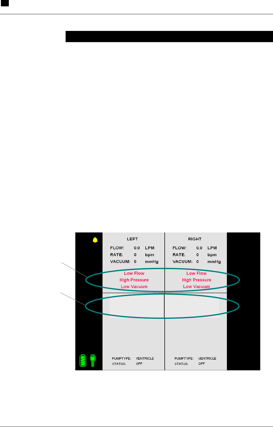
7 VAD Support
VAD Alarms
7.16 RECOVER BP IABP/VAD System – Operator’s Manual
Check Blood Pump:
-Disconnect or leak
in drive line.
Check Blood Pump:
-Drive line or blood
pump lines kinked
or occluded.
VAD Alarms
The Console monitors various functions to determine whether its
operating parameters are within expected limits. When a parameter
goes outside of its limits, the Console displays an alarm message and
sounds an alarm tone. The severity of the alarm is indicated by the
color of the alarm message text and by the characteristics of the alarm
tone ****[verify details].
Levels of Severity
Alarms are divided into two levels of severity:
• Life-Threatening – Red
• Serious – Yellow
A maximum of six alarms (three Left and three Right) are displayed
on the VAD screen (see Figure 32). When an alarm condition occurs,
pressing HELP on the System keypad opens a help window that
describes the action(s) to take to resolve the alarm.
Figure 32 VAD Alarm Messages and Help Text
Alarm
Messages
Action(s) to take to
resolve the alarm

VAD Support 7
VAD Alarms
RECOVER BP IABP/VAD System – Operator’s Manual 7.17
VAD Alarm Messages and Help Text
Tables 17 and 18 show all VAD alarm messages and help text.
Table 18 VAD Red Alarm Messages and Help Text
RED ALARMS Category: Life-Threatening
Alarm Message
Action
LOW FLOW Check Blood Pump:
1. Obstruction of blood
lines.
2. Blood Pump placed
too high relative to
atrium.
3. Inadequate blood
volume.
HIGH PRESSURE Internal pressure
problem:
1. Obtain backup
Console.
LOW PRESSURE Internal pressure problem
if indicated when not
pumping:
1. Obtain backup
Console.
HIGH VACUUM Internal vacuum problem:
1. Obtain backup
Console.
LOW VACUUM Internal vacuum problem:
1. Obtain backup
Console.
SYSTEM FAILURE
Keypad Failure - Change to Backup Console
(Displayed in Help window)
Keypad not
working/connected:
1. Check keypad
connection.
2. Switch to backup
Console.
3. Call for service.

7 VAD Support
VAD Alarms
7.18 RECOVER BP IABP/VAD System – Operator’s Manual
Table 19 VAD Yellow Alarm Messages and Help Text
YELLOW ALARMS Category: Serious
Alarm Message
Action
PUMP ID
Pump ID Disconnected (displayed in help
window)
Re-attach Ventricle
electrical/pneumatic
connector to Console.
PUMP ID
New Pump ID Detected (displayed in help
window)
Check Ventricle
electrical/pneumatic
connector:
1. Turn pump OFF and
then ON again to
change pump type
selected by Console.

VAD Support 7
Using the Hand Pump
RECOVER BP IABP/VAD System – Operator’s Manual 7.19
Using the Hand Pump
If the Console fails (stops pumping), the supplied RECOVER BP
Hand Pump allows manual operation of the Ventricle or the BVS®
Pump. The Hand Pump is stored on the side of the Console.
The Hand Pump may be operated while mounted on the Console, or it
may be removed and held during operation.
Transferring to the Hand Pump
1 Turn off and unplug the Console.
2 Remove the Ventricle or BVS Pump driveline(s) from the
Console connector.
3 Connect the driveline(s) to the Hand Pump. The Left pump
driveline goes to the Left connector, and the Right pump
driveline goes to the Right connector.
4 Set the Hand Pump shuttle mechanism to the position appropriate
for the blood pump in use.
5 Pull the Hand Pump handle until it stops.
6 Push the handle to fully return it to its original position.
7 Continue pumping at a rate of 30 to 60 times per minute.
8 Observe the Ventricle or BVS Pump for proper filling and
emptying.
Transferring from the Hand Pump to a Backup Console
1 Plug the backup Console power cord into an AC outlet.
2 Turn the Console ON and allow the Self-Test to run.
3 Transfer the driveline(s) from the Hand Pump to the backup
Console.

7 VAD Support
Using the Hand Pump
7.20 RECOVER BP IABP/VAD System – Operator’s Manual
4 Begin pumping by pressing the ON key for the appropriate side
(Left or Right). If both sides are being supported, press the Left
ON key first.
5 If necessary, return the Hand Pump to the Console holder.
6 Contact service personnel as soon as possible to repair the failed
Console.

8.1
8 Emergency System Operation (ESO)
Contents
ESO Enabled During IABP Support.......................................................................8.2
ESO Enabled During VAD Support........................................................................8.2
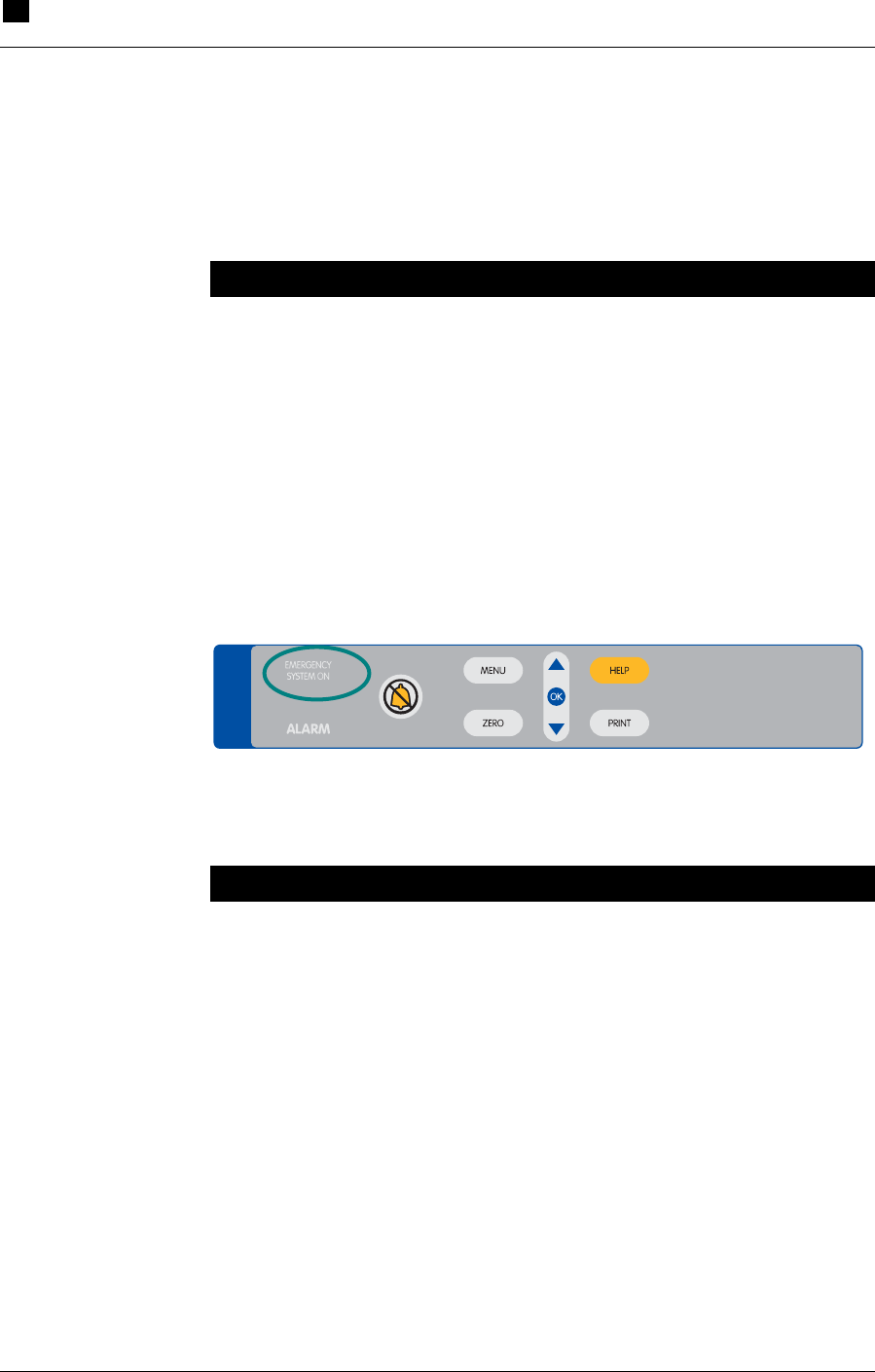
8 Emergency System Operation (ESO)
ESO Enabled During IABP Support
8.2 RECOVER BP IABP/VAD System – Operator’s Manual
The RECOVER BP Console monitors its operating parameters and
automatically enables the Emergency System Operation (ESO) mode
if a serious problem is detected. The effects on Console operation are
dependent on whether IABP or VAD support is in progress.
ESO Enabled During IABP Support
When ESO is enabled, the Console performs the following actions:
• Stops IAB pumping.
• Deflates and vents the IAB.
• Activates an alarm.
• Turns on the ESO indicator light on the System keypad (see
Figure 33).
SYSTEM
Figure 33 Emergency System Operation (ESO) Indicator
ESO Enabled During VAD Support
When ESO is enabled, the Console performs the following actions:
• Changes to a fixed-rate control system and continues pumping at
approximately 75 bpm.
• Activates an alarm.
• Turns on the ESO indicator light on the System keypad (see
Figure 33).

9.1
9 Clinical Considerations
Contents
Effects of Electrosurgical Equipment .....................................................................9.2
Effects of Defibrillation Equipment .........................................................................9.2

9 Clinical Considerations
Effects of Electrosurgical Equipment
9.2 RECOVER BP IABP/VAD System – Operator’s Manual
Effects of Electrosurgical Equipment
The RECOVER BP Console may exhibit the following effects during
the use of electrosurgical equipment:
• Display becomes blank or distorted
• Alarm sounds
• Pumping stops or becomes erratic
The display and the pumping function will resume normal operation
within 10 seconds after the completion of electrosurgery.
Effects of Defibrillation Equipment
WARNING: Be extremely careful when a defibrillator is used on a
patient. Dangerous high voltage is present during defibrillation. Do
NOT touch the Console, patient, table, accessories, cables, or any
connected equipment.
The Console is classified as Type CF defibrillation-proof
(IEC 60601-1) equipment.
The following effects may occur during defibrillation:
• Display becomes blank or distorted
• Alarm sounds
• Pumping stops or becomes erratic
The display and the pumping function will resume normal operation
within 10 seconds after the completion of defibrillation.

10.1
10 Installation and Maintenance
Contents
Installation............................................................................................................10.2
Checking the Console Before Each Use..............................................................10.2
Periodic Testing of Backup Systems....................................................................10.3
Testing the Hand Pump ................................................................................10.3
Testing ESO .................................................................................................10.3
Cleaning...............................................................................................................10.4
Console.........................................................................................................10.4
Patient ECG Cable .......................................................................................10.4
Preventive Maintenance ......................................................................................10.5
Ordering Information............................................................................................10.6
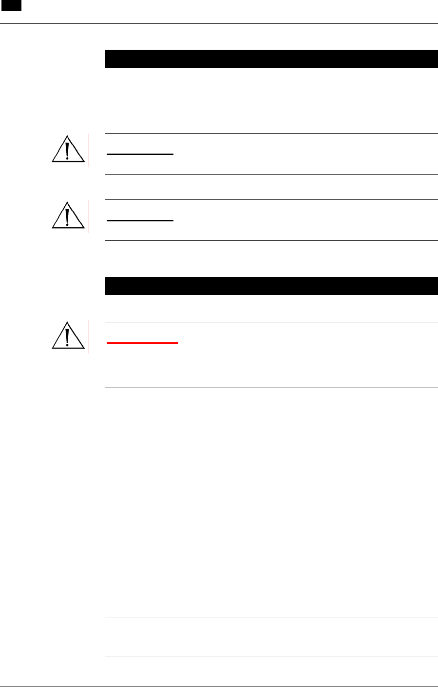
10 Installation and Maintenance
Installation
10.2 RECOVER BP IABP/VAD System – Operator’s Manual
Installation
Prior to clinical use, installation and testing of the Console shall be
performed by an authorized ABIOMED® Service Representative.
CAUTION: The RECOVER BP Console must be plugged into AC
power to maintain a charged battery.
CAUTION: To remove all AC power from the Console, unplug the
power cord from the AC outlet.
Checking the Console Before Each Use
WARNING: The RECOVER BP Console does not contain any
user-serviceable parts. To reduce the risk of electric shock, do NOT
attempt to remove the Console housing or to replace the Console
Battery.
Prior to each clinical use, perform the following checks to determine
that the Console is working properly and is ready to use:
1 Visually inspect for physical damage to the equipment housing,
display, and power cord. Be sure that all required parts of the
System, such as cables and the Hand Pump, are present.
2 Turn the Console ON using the AC power switch on the left side.
3 Allow the Console to complete the Self-Test. Verify that all
indicator lights work and air audibly vents from the left and right
driveline connectors. Verify that the audible alarm indicator is
operating properly by listening for the alarm tone during the Self-
Test.
NOTE: The audible alarm indicator can be tested during Console
operation by pressing any ON or OFF key whose indicator light is on.

Installation and Maintenance 10
Periodic Testing of Backup Systems
RECOVER BP IABP/VAD System – Operator’s Manual 10.3
Periodic Testing of Backup Systems
Regularly test the Console's backup systems, which are the Hand
Pump and the Emergency System Operation (ESO) feature.
Testing the Hand Pump
Operate the Hand Pump handle through its full range of motion and
verify that air audibly vents from the left and right driveline
connectors.
Testing ESO
1 Turn the Console ON. Within 30 seconds, simultaneously press
both WEAN keys for at least 3 seconds.
2 Verify that a continuous audible alarm sounds and the ESO
indicator light flashes.
3 Press the left and right Ventricular Assist ON keys. Check that
the Rate indicator lights blink and that air vents from the
driveline connectors as the Console pumps.
4 Turn the Console OFF to deactivate ESO.

10 Installation and Maintenance
Cleaning
10.4 RECOVER BP IABP/VAD System – Operator’s Manual
Cleaning
CAUTION: Do NOT pour liquid, including cleaning solution,
directly on any part of the Console. Doing so can cause electrical
malfunction.
If liquid is accidentally spilled on the Console, be sure to thoroughly
dry the affected area. Wait at least 15 minutes, after drying, before
turning the Console ON. Verify that the Self-Test runs and indicates
that the unit is operating properly.
Console
It is recommended that the Console be cleaned after each use. Turn
the Console OFF before you clean it.
To clean the display/control panel area, use cotton and 70% isopropyl
alcohol, or a soft cloth with soap and water.
To clean the housing, use a damp cloth and a mild detergent solution.
Patient ECG Cable
Clean and disinfect the patient ECG cable after each use by
performing the procedure described in the Instructions for Use
supplied with the cable or by following hospital operating procedures.

Installation and Maintenance 10
Preventive Maintenance
RECOVER BP IABP/VAD System – Operator’s Manual 10.5
Preventive Maintenance
The following preventive maintenance items are to be performed only
by an authorized ABIOMED® Service Representative.
Table 20 Preventive Maintenance Intervals
Component/Subsystem Interval
Battery One calendar year
Solenoid Valve 5000 hrs. operating time
Proportional Valve 2500 hrs. operating time
Compressor 2500 hrs. operating time
IABP 5000 hrs. operating time
10 Installation and Maintenance
Ordering Information
10.6 RECOVER BP IABP/VAD System – Operator’s Manual
Ordering Information
Table 21 Ordering Information for RECOVER BP Console
Catalog No. Language Nominal Voltage
0036-0000 English 120 VAC
****[?] English 230 VAC
Table 22 Ordering Information for Parts
Catalog No. Description Contents
0036-0030 Cart 1 per box
0015-0040 Aircraft Mounting Plate 1 per box
0050-3200 BVS® Blood Pump Sling 1 per box
0005-0090 BVS® IV Pole Mount 1 per box
0005-0080 BVS® Bed Mount 1 per box
0005-0060 BVS® Pump Mount Set 1 per box
0036-2754 Patient Cable Set ****[?]
****[?] Edwards Lifesciences TruWave
Disposable Pressure Transducer
(supplied sterile)
****[?]
0036-6300 *Helium Cylinder, 93 L ****[?]
2500-0133 *Helium Yoke Sealing Washer ****[?]
2000-0009 Chart Recorder Paper, Thermal,
2-inch Roll ****[?]
****[?] Adapter for Datascope® 8F (40 cc)
IAB Catheter ****[?]
****[?] RECOVER BP IABP/VAD System
Operator's Manual 1 per box
****[?] RECOVER BP IABP/VAD System
Service Manual 1 per box
* This is a refillable cylinder. Ownership of this cylinder has been established by sale
to the purchaser. Refill may be arranged by contacting your local gas supplier or by
contacting Linde Specialty Gas Customer Service at 1-800-837-7226. Refiller is
required to relabel this product with their own label. Do not refill without properly
labeling.
This cylinder may also be recycled by following the instructions below:
1. Using a properly installed regulator, slowly vent residual gas until empty.
2. Vent gas slowly into a well ventilated area, preferably outdoors.
3. Remove the regulator, let valve open. Write "EMPTY" on cylinder.
4. Deface any hazardous materials information labels.
5. Cylinder may be discarded as scrap metal or solid waste.
6. Check with local solid waste authority to ensure local regulatory compliance.
7. Questions? Contact Linde Specialty Gas Customer Service at 1-800-837-7226.
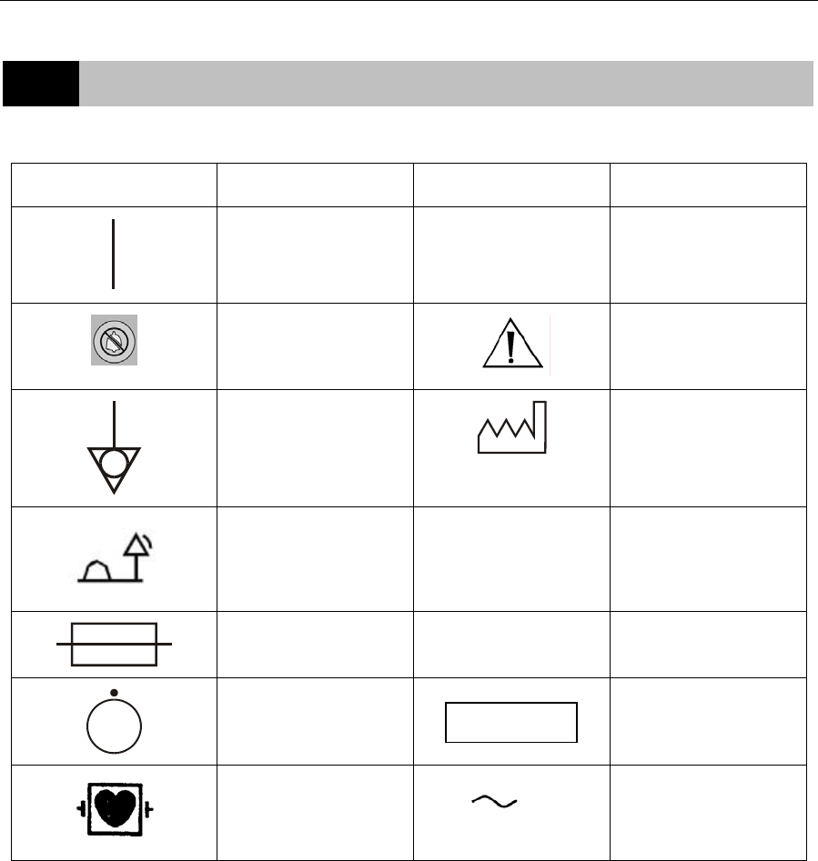
11.1
11 Symbol Descriptions
Symbol Description Symbol Description
"ON" (power) IPX1 Protected against
dripping water
Alarm silence
Attention, consult
instructions
Equipotentiality
Year of manufacture
Remote alarm output
SN Serial number
Fuse REF Part number
"OFF" for a part of
equipment
Lot number
Type CF Equipment
defibrillator-proof Alternating current
LOT

12.1
12 System Specifications
Contents
Console Mechanical.............................................................................................12.2
Console Electrical ................................................................................................12.4
Equipment Design................................................................................................12.5
Equipment Classifications....................................................................................12.6
Federal Communications Commission (FCC) Notice...........................................12.7
Electromagnetic Compatibility..............................................................................12.7
Patient Environment...........................................................................................12.12

12 System Specifications
Console Mechanical
12.2 RECOVER BP IABP/VAD System – Operator’s Manual
Console Mechanical
****[reformat]
Attribute Specification
Temperature Operating: 10°C to 40°C (50°F to 104°F)
Storage: -15°C to 50°C (5°F to 122°F)
Relative Humidity Operating: 30% to 75%
Storage: 10% to 95%, noncondensing
Atmospheric Pressure
Operating: 8000 ft (750 hPa) to -1000 ft
(1050 hPa)
Storage: 18,000 ft (500 hPa) to -1000 ft
(1050 hPa)
Dimensions – Transport &
Hospital Configuration
Transport (w/o Cart) Hospital (w/ Cart)
Height: 34 in. (86.4 cm) 41 in. (104.1 cm)
Width: 23 in. (58.4 cm) 28 in. (71.1 cm)
Depth: 11 in. (27.9 cm) 18 in. (45.7 cm)
Dimensions – Packaged
Configuration
Console Cart
Height: 24 in. (61.0 cm) 28 in. (71.1 cm)
Width: 30 in. (76.2 cm) 33 in. (83.8 cm)
Depth: 38 in. (96.5 cm) 45 in. (114.3 cm)
Weight – Transport &
Hospital Configuration Transport (w/o Cart) Hospital (w/ Cart)
Maximum: 126 lb (57.2 kg) 190 lb (86.2 kg)
Weight – Packaged
Configuration Console Cart
Maximum: ****[X] lb ****[X] lb
Left-Side Flow Rate
Under normal operation, the Console must produce a minimum blood
flow through the VAD for both pumps as follows:
Minimum: 4.8 L/min at outflow pressure of 90 mmHg (1.7 psi) and
inflow pressure > 10 mmHg (0.2 psi) for 42 Fr Atrial Cannula used
with 42 Fr or 10 mm Arterial Cannula.
Minimum: 4.0 L/min at outflow pressure of 90 mmHg (1.7 psi) and
inflow pressure > 10 mmHg (0.2 psi) for 32 Fr and 36 Fr Atrial
Cannula used with 42 Fr or 10 mm Arterial Cannula.
Method: Blood flow rate calculated based on integration of airflow
signal.
Right-Side Flow Rate
Under normal operation, the Console must produce a minimum blood
flow through the VAD as follows:
Minimum: 4.8 L/min at outflow pressure of 40 mmHg (0.8 psi) and
inflow pressure > 10 mmHg (0.2 psi) for 42 Fr Atrial Cannula used
with 42 Fr or 10 mm Arterial Cannula.
Minimum: 4.0 L/min at outflow pressure of 40 mmHg (0.8 psi) and
inflow pressure > 10 mmHg (0.2 psi) for 32 Fr and 36 Fr Atrial
Cannula used with 42 Fr or 10 mm Arterial Cannula
Method: Blood flow rate calculated based on integration of airflow
signal.

System Specifications 12
Console Mechanical
RECOVER BP IABP/VAD System – Operator’s Manual 12.3
Console Mechanical (continued)
****[reformat]
Attribute Specification
Displayed Flow Accuracy
At altitudes between min/max range, flow accuracy is as follows:
Left Side: ± 15% over the following ranges:
Inflow Pressure 5 to 25 mmHg (0.1 to 0.5 psi)
Outflow Pressure 60 to 90 mmHg (1.2 to 1.7 psi)
Right Side: ± 15% over the following ranges:
Inflow Pressure 5 to 15 mmHg (0.1 to 0.3 psi)
Outflow Pressure 30 to 40 mmHg (0.6 to 0.8 psi)
At elevations greater than maximum specified altitude range, flow
rates displayed on Console may underreport flows by as much as 1.0
L/min.
Beat Rate
The Console must determine and display the VAD beat rate.
Range: 0 – 150 bpm
Resolution: 1 bpm
Accuracy: ± 3 bpm or ± 3 %, whichever is greater
Timing
AUTO Mode
Automatically and continually optimizes inflation & deflation timing.
MANUAL Mode
Allows the user to manually adjust inflation / deflation timing.
Method: Percentage based on 4-beat average of beat-to-
beat interval (ECG, AP, A-Pacer, V-Pacer).
Percentage based on 4-beat average of 80 bpm
Heart Rate (Internal).
Inflation Range: 20 – 80 % (ECG, A-Pacer, V-Pacer, Internal)
0 – 35 % (AP)
Inflation Default: 45 % (ECG, A-Pacer, V-Pacer, Internal) 10 % (AP)
Deflation Range: 30 – 100 % (ECG, Internal) 35 – 75 % (AP)
30 – 120 % (A-Pacer, V-Pacer)
Deflation Default:
80 % (ECG, A-Pacer, V-Pacer) 40 % (AP)
80 % (Internal)
Heart Rate
The Console must determine and display the heart rate.
Range: 30 – 200 bpm
Resolution: 1 bpm
Accuracy: ± 3 bpm or ± 3% whichever is greater
Display Update Rate: 2 ± 0.5 sec

12 System Specifications
Console Electrical
12.4 RECOVER BP IABP/VAD System – Operator’s Manual
Console Electrical
****[reformat]
Attribute Specification
Console AC operation: 100 – 230 VAC (nominal); 50/60 Hz; 4 A
Internal battery operation: 24.0 VDC (nominal); sealed lead-acid
ECG
Lead Input Support: 5 Lead Cable (AAMI or IEC)
Electrodes: RA, LA, LL, RL, V
Sampled Leads: I, II, V’
Derived Leads: III, aVR, aVL, AVF, V
Range: ± 300 mV (DC) ± 80 mV (AC)
Frequency Response: 0.4 – 100 Hz (-3dB) ****[TBD] 0.6 – 85 Hz
Minimum Input Impedance: 2.5 MΩ
Pacer Pulse Detection: On each sampled Lead
Pacer Sensitivity: down to 1.54 V/s per AAMI EC13-2002 4.1.4.3
Lead Fault Detection: When any active electrode open
Defibrillator Protection: compliance to IEC601-2-27
Defibrillator Recovery Time: compliance to IEC601-2-27
Electrosurgical Interference Suppression: Operation of an
Electrosurgical Unit must not cause an unrecoverable malfunction.
Default Waveform Sweep Speed: 25 mm/sec
Arterial Pressure
The Console must determine and display Arterial Pressure.
Parameters: assisted systole, unassisted systole, assisted end
diastole, unassisted end diastole, mean, augmented diastole, and AP
waveform.
Nominal Sensitivity: 5 µV / V / mmHg
Range: 0 – 300 mmHg (5.8 psi)
Resolution: 1 mmHg (.02 psi)
Frequency Response: 0 – 40 Hz (-3dB)
Accuracy: ± 2 mmHg (.04 psi) or ± 2% whichever is greater (not
including transducer)
Display Update Rate: 2 ± 0.5 sec
Default Waveform Sweep Speed: 25 mm/sec
Doppler
Tethered and retractable 8 MHz hand-held non-directional probe.
Minimum Length: 6 ft (1.8 m), uncoiled
Audible Output: Integral speaker with volume control
Minimum Audible Level: 73 dB @ 1 ft (0.3 m)
Power Source: Battery Powered

System Specifications 12
Equipment Design
RECOVER BP IABP/VAD System – Operator’s Manual 12.5
Equipment Design
The RECOVER BP System is designed to comply with the
requirements of the following standards:
• IEC 60601-1: 1988 + A1:1991 + A2:1995
• IEC 60601-1-1: 2000
• IEC 60601-2-27: 1994 (First Edition)
• IEC 60601-2-34: 2000 (Second Edition)

12 System Specifications
Equipment Classifications
12.6 RECOVER BP IABP/VAD System – Operator’s Manual
Equipment Classifications
Type of protection against
electric shock
IEC 60601-1: Class I and internally
powered. Relies not only on basic
insulation against shock but also
includes additional protection.
Accomplished by providing means for
connecting the equipment to the
protective earth conductor of the fixed
wiring of the installation in a way that
prevents accessible metal parts from
becoming live if basic insulation fails.
Degree of protection against
electric shock
Console
IAB
Pressure transducer
ECG
IEC 60601-1: Type CF defibrillation-
proof
IEC 60601-1: Type CF defibrillation-
proof
IEC 60601-1: Type CF defibrillation-
proof
IEC 60601-1: Type CF defibrillation-
proof
Mode of Operation
Continuous.
Degree of protection against
explosion hazard
Not suitable for use in the presence of a
flammable anesthetic mixture with air or
with oxygen or nitrous oxide. Also not
suitable for use in an oxygen-enriched
atmosphere.
Degree of protection against
harmful ingress of water
IEC 60529: IPX1 protected against
dripping water.
Cleaning Methods
Console
Patient ECG Cable
Display/control panel: 70% isopropyl
alcohol, or soap and water.
Housing: mild detergent.
Per manufacturer's Instructions for Use
or per hospital operating procedures.
System Specifications 12
Electromagnetic Compatibility
RECOVER BP IABP/VAD System – Operator’s Manual 12.7
Federal Communications Commission
(FCC) Notice
This device complies with Part 15 of the FCC Rules. Operation is
subject to the following two conditions: (1) This device may not cause
harmful interference, and (2) this device must accept any interference
received, including interference that may cause undesired operation.
Changes or modifications not expressly approved by ABIOMED, Inc.
could void the user's authority to operate this device.
Electromagnetic Compatibility
WARNING: Medical Electrical Equipment needs special
precautions regarding EMC and needs to be installed and put into
service according to the Electromagnetic Compatibility (EMC)
information provided in the accompanying documents.
WARNING: Portable and Mobile RF Communications Equipment
can affect Medical Electrical Equipment.
WARNING: The Equipment or System should not be used
adjacent to or stacked with other equipment. If adjacent or stacked
use is necessary, the Equipment or System should be observed to
verify normal operation in the configuration in which it will be used.
NOTE: The EMC tables and other guidelines that are included in
the Operator's Manual provide information to the customer or user
that is essential in determining the suitability of the Equipment or
System for the Electromagnetic Environment of Use, and in
managing the Electromagnetic Environment of Use permit the
Equipment or System to perform to its intended use without
disturbing other Equipment and Systems or non-Medical Electrical
Equipment.

12 System Specifications
Electromagnetic Compatibility
12.8 RECOVER BP IABP/VAD System – Operator’s Manual
TABLE 201
Guidance and Manufacturer's Declaration – Emissions All Equipment and Systems
The RECOVER BP Console is intended for use in the electromagnetic environment specified
below. The customer or user of the RECOVER BP Console should ensure that it is used in such
an environment.
Emissions Test Compliance Electromagnetic Enforcement – Guidance
RF Emissions
CISPR 11 Group 1 The RECOVER BP Console uses RF energy only
for its internal function. Therefore, its RF emissions
are very low and are not likely to cause any
interference in nearby electronic equipment.
RF Emissions
CISPR 11 Class A
Harmonics
IEC 61000-3-2 Class A
Flicker
IEC 61000-3-3 Complies
The RECOVER BP Console is suitable for use in all
establishments other than domestic, and those
directly connected to the public low-voltage power
supply network that supplies buildings used for
domestic purposes.

System Specifications 12
Electromagnetic Compatibility
RECOVER BP IABP/VAD System – Operator’s Manual 12.9
TABLE 202
Guidance and Manufacturer's Declaration – Immunity All Equipment and Systems
The RECOVER BP Console is intended for use in the electromagnetic environment specified
below. The customer or user of the RECOVER BP Console should ensure that it is used in such
an environment.
Immunity Test IEC 60601
Test Level Compliance
Level Electromagnetic Environment –
Guidance
Electrostatic
Discharge (ESD)
IEC 61000-4-2
±6 kV contact
±8 kV air
±6 kV contact
±8 kV air
Floors should be wood, concrete
or ceramic tile. If floors are
synthetic, the relative humidity
should be at least 30%.
Electrical Fast
Transient/burst
IEC 61000-4-4
±2 kV Mains
±1 kV for
input/output lines
±2 kV Mains
±1 kV for
input/output lines
Mains power quality should be that
of a typical commercial or hospital
environment.
Surge
IEC 61000-4-5 ±1 kV Differential
±2 kV Common
±1 kV Differential
±2 kV Common
Mains power quality should be that
of a typical commercial or hospital
environment.
Voltage dips, short
interruptions and
voltage variations
on power supply
input lines
IEC 61000-4-11
> 95% dip for 0.5
cycle
60% dip for 5
cycles
30% dip for 25
cycles
> 95% dip for 5
seconds
> 95% dip for 0.5
cycle
60% dip for 5
cycles
30% dip for 25
cycles
> 95% dip for 5
seconds
Mains power quality should be that
of a typical commercial or hospital
environment. If the user of the
RECOVER BP Console requires
continued operation during power
mains interruptions, it is
recommended that the RECOVER
BP Console be powered from an
uninterruptible power supply or
battery.
Power Frequency
50/60Hz Magnetic
Field
IEC 61000-4-8
3 A/m 3 A/m Power frequency magnetic fields
should be that of a typical location
in a typical commercial or hospital
environment.
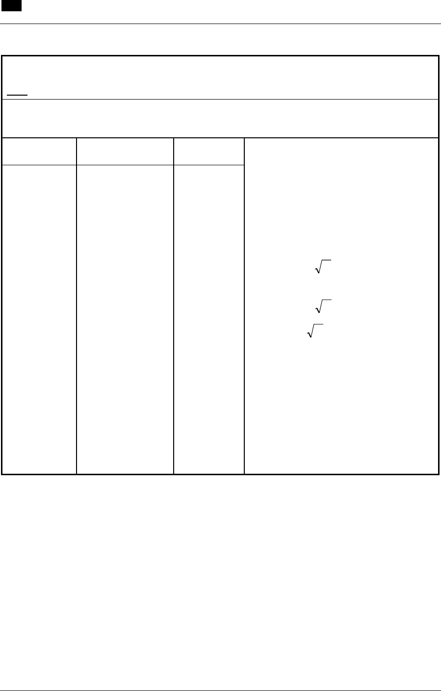
12 System Specifications
Electromagnetic Compatibility
12.10 RECOVER BP IABP/VAD System – Operator’s Manual
TABLE 204
Guidance and Manufacturer's Declaration – Emissions Equipment and Systems that are
NOT Life-Supporting
The RECOVER BP Console is intended for use in the electromagnetic environment specified
below. The customer or user of the RECOVER BP Console should ensure that it is used in such
an environment.
Immunity
Test IEC 60601
Test Level Compliance
Level
Conducted RF
IEC 61000-4-6
Radiated RF
IEC 61000-4-3
3 Vrms
150 kHz to 80 MHz
3 V/m
80 MHz to 2.5 GHz
V1 = 3 Vrms
E1 = 3 V/m
Electromagnetic Environment –
Guidance
Portable and mobile RF communications
equipment should be separated from the
RECOVER BP Console by no less than
the recommended separation distances
calculated/listed below:
PVD )1/5.3(=
PED )1/5.3(= 80 to 800 MHz
PED )1/7(= 800 MHz to 2.5 GHz
Where P is the maximum power rating in
watts and D is the recommended
separation distance in meters.
Field strengths from fixed transmitters, as
determined by an electromagnetic site
survey, should be less than the
compliance levels (V1 and E1).
Interference may occur in the vicinity of
equipment containing a transmitter.
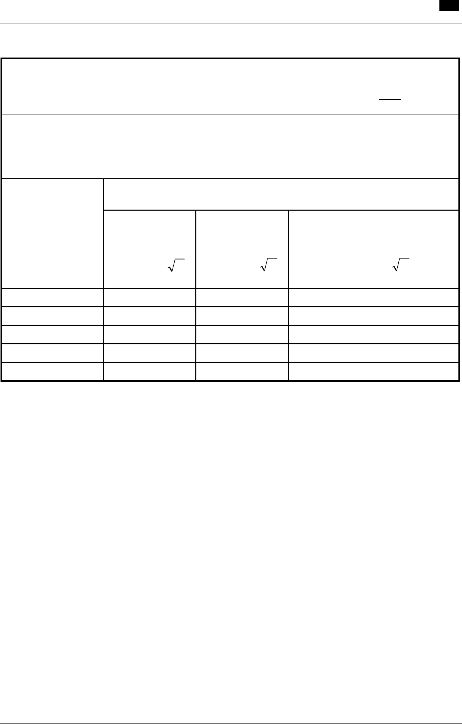
System Specifications 12
Electromagnetic Compatibility
RECOVER BP IABP/VAD System – Operator’s Manual 12.11
TABLE 206
Recommended Separation Distances Between Portable and Mobile RF Communications
Equipment and the RECOVER BP Console Equipment and Systems that are NOT Life-
Supporting
The RECOVER BP Console is intended for use in the electromagnetic environment in which
radiated disturbances are controlled. The customer or user of the RECOVER BP Console can
help prevent electromagnetic interference by maintaining a minimum distance between Portable
and Mobile RF Communications Equipment and the RECOVER BP Console as recommended
below, according to the maximum output power of the communications equipment.
Recommended Separation Distances for the RECOVER BP Console
Maximum Output
Power (Watts) 150 KHz to
80 MHz
Pd 1667.1=
80 to 800 MHz
Pd 1667.1=
800 MHz to 2.5 GHz
Pd 3333.2=
0.01
0.11667
0.11667
0.23333
0.1
0.36894
0.36894
0.73785
1
1.1667
1.1667
2.3333
10
3.6894
3.6894
7.3785
100
11.667
11.667
23.333
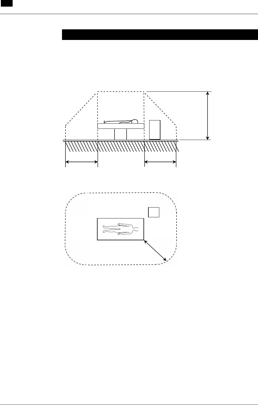
12 System Specifications
Patient Environment
12.12 RECOVER BP IABP/VAD System – Operator’s Manual
Patient Environment
The RECOVER BP Console and the components of the RECOVER
BP System are the only items approved for use within the patient
environment defined in IEC 60601-1-1 and in the figure below.
1.5 m
2.5 m
1.5 m
CONSOLE
1.5 m
CONSOLE

ABIOMED, Inc.
22 Cherry Hill Drive
Danvers, MA 01923 USA
978-777-5410
978-777-8411 (fax)
clinical@abiomed.com
www.abiomed.com
24-Hour Emergency Hotline: N. America 1-800-422-8666
September 2006 DRAFT
Document No. x Rev. 2
®