ACCO M01042-V Hands-Free Visor Car Kit for iPhone & BT Phones User Manual PES K33440 280508
ACCO Brands, Inc. Hands-Free Visor Car Kit for iPhone & BT Phones PES K33440 280508
UserManual.wiki
>
ACCO
>
M01042 V User Manual
Users Manual
Navigation menu
Upload a User Manual
Namespaces
Wiki Guide
HTML
PDF
Info
Views
User Manual
Discussion / Help
Navigation
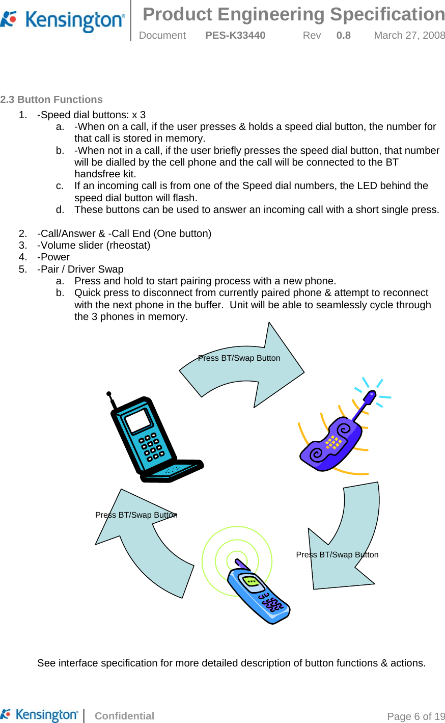
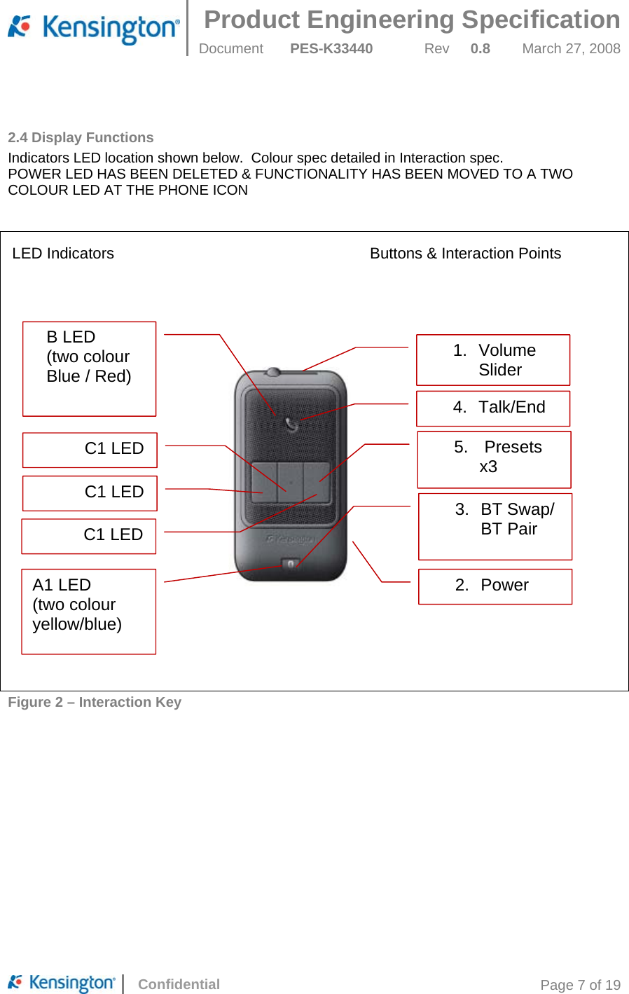
![Product Engineering Specification Document PES-K33440 Rev 0.8 March 27, 2008 Confidential Page 8 of 19 3.0 Electrical Specifications This product is a standard BT handsfree visor product with a few additional features. 3.1 General Description Firmware is to be written to follow requirements of interaction spec with the smarts to store 3 individual presets for each paired phone. For example, PhoneA presets could be different from PhoneB. The firmware will be smart enough to remember the BT Phone ID and allocate the separate memory location for presets for that phone. Therefore, there are actually 9 presets stored in the device. Whenever a BT phone with an ID already listed in the device, it is moved to the top of the list and the corresponded presets are loaded. When a phone ID not listed in the device is paired, the memory location for the one on the bottom of the list will be used overwriting the old ID and clearing all presets while moving the phone ID to the top of the list. 3.2 Interface Description See in appendix 3.3 Power Requirements Talk time: up to 6 hours Standby time: up to 7 days. Power provided by a user-replaceable NiMH battery 800mAh Recharging circuitry for NiMH battery is included in CLA battery charger. USB port on CLA charger must meet iPhone power requirements listed in 3.8 3.4 BT Requirements Chipset: CSR BC05 BT 2.1 Paired devices limited to 3 phones. One at a time 3.5 Audio Requirements • Audio Out: Speaker o Power (minimum) : 1W continuous,1.5- 2W peak. o Sensitivity (SPL): min 82 +/- 3dB o Impedance: 8 Ohm +/- 15% o Lowest resonant frequency [Fo]: 280 – 480 Hz o Effective frequency Range (minimum): Fo – 10kHz o THD < 5% o Recommended speaker VECO P40DS08G-3-75ND • Audio In: measurement method tbd o Generally the intent is to filter out all external noise factors including but not limited to: • Road Noise • Car Noise • Wind Noise • Tire Noise • Echo](https://usermanual.wiki/ACCO/M01042-V/User-Guide-1028362-Page-8.png)