ACCO M01042-V Hands-Free Visor Car Kit for iPhone & BT Phones User Manual PES K33440 280508
ACCO Brands, Inc. Hands-Free Visor Car Kit for iPhone & BT Phones PES K33440 280508
ACCO >
Users Manual

Confidential
Product Engineering Specification
Codename:ET-Visor
K33440
Document Title Product Engineering Specification
Document Number PES-K33440
Prepared By Matthew Hoag
Reviewed By Betsy Diaz
Last Modified May 28, 2008
Creation Date November 22, 2007
Revision 0.8
Status Draft
Product Engineering Specification
Document PES-K33440 Rev 0.8 March 27, 2008
Confidential Page 2 of 19
Revision History
Modified By Date Revision Reason for Change
Matt Hoag January 11, 2008 0.1 First Draft
Gary Wong January 22, 2008 0.2 Detail BT behaviour
Matt Hoag January 25, 2008 0.3 Updated charging scheme
Matt Hoag Feb 22, 2008 0.4 Released to Primax for
comments
Matt Hoag March 12, 2008 0.5 Updated configuration &
components
Matt Hoag March 27, 2008 0.6 Updated Speaker spec
Matt Hoag April 28, 2008 0.7 Updated QA section
Matt Hoag May 28, 208 0.8 Updated for Tooling release
2.3 Swap button function
clarified
2.4 LED behaviour changed
1.0 Released
1.1 Modified
Product Information
Product Name Codename: ET_Visor - Bluetooth Visor Car Hands free Kit
Product Description Visor Mounted BT Handsfree kit
Product Number K33440
Product Manager Kevin Ngo
Project Manager Matthew Hoag

Product Engineering Specification
Document PES-K33440 Rev 0.8 March 27, 2008
Confidential Page 3 of 19
Table of Contents
1.0 Introduction.............................................................................................................................. 4
1.1 Scope .................................................................................................................................... 4
1.2 Purpose................................................................................................................................. 4
1.3 Reference.............................................................................................................................. 5
1.4 Acronyms .............................................................................................................................. 5
2.0 Functional Specifications....................................................................................................... 5
2.1 General Description .............................................................................................................. 5
2.2 System Diagram.................................................................................................................... 5
2.3 Button Functions ................................................................................................................... 6
2.4 Display Functions.................................................................................................................. 7
3.0 Electrical Specifications ......................................................................................................... 8
3.1 General Description .............................................................................................................. 8
3.2 Interface Description ............................................................................................................. 8
3.3 Power Requirements............................................................................................................. 8
3.4 BT Requirements .................................................................................................................. 8
3.5 Audio Requirements.............................................................................................................. 8
3.6 Recharging requirements...................................................................................................... 9
3.7 Battery Pack Specifications................................................................................................... 9
3.8 USB Battery Charger: ........................................................................................................... 9
3.9 CLA USB Power adapter Specifications: .............................................................................. 9
4.0 Mechanical Specifications.................................................................................................... 11
4.1 Industrial Design Considerations ........................................................................................ 11
4.2 Component and Assembly Specifications........................................................................... 12
4.3 Bill of Materials.................................................................................................................... 12
4.4 Material Specifications ........................................................................................................ 12
4.5 Tooling Specifications ......................................................................................................... 12
4.6 Compliance and Recycling Requirements.......................................................................... 12
4.7 Product Labelling Requirements......................................................................................... 12
5.0 Software Specifications........................................................................................................ 13
5.1 General Specifications ........................................................................................................ 13
N/A............................................................................................................................................. 13
5.2 Compatibility Requirements ................................................................................................ 13
5.3 Installation Requirements.................................................................................................... 13
6.0 Product Packaging, Labelling and Documentation ........................................................... 14
6.1 Packaging Name................................................................................................................. 14
6.2 Box Structure Materials Specifications................................................................................ 14
6.3 Bill of Materials of Packaging..............................................................................................14
6.4 Sample Photo of Prior Design............................................................................................. 14
6.5 Sample Photo and/or Drawing of ALL die cut components ................................................ 14
6.6 Sample Photo and/or Drawing of Assembly of all Component parts.................................. 14
7.0 Environmental Specifications.............................................................................................. 15
8.0 Regulatory Requirements.....................................................................................................16
8.1 Region Regulatory Requirements ................................................................................. 16
8.2 Environmental & Energy Compliance Requirements .................................................... 16
8.3 OEM Specific Requirements ......................................................................................... 16
9.0 Quality Requirements ........................................................................................................... 17
9.1 Design Workload................................................................................................................. 17
9.2 Reliability Requirements ..................................................................................................... 17
9.3 Acceptance Quality Level....................................................................................................17
10.0 Approval............................................................................................................................... 18
Product Engineering Specification
Document PES-K33440 Rev 0.8 March 27, 2008
Confidential Page 4 of 19
1.0 Introduction
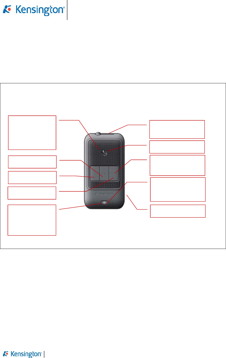
ET-Visor is a Bluetooth enabled automotive speaker phone which is visor mounted. The controls
on the product & the pairing process is “Smart Made Simple”
…….
Figure 1 – Preliminary product images
1.1 Scope
This document outlines the Electrical Specifications, ID Considerations, Mechanical
Specifications and Tooling Requirements necessary to produce the product.
1.2 Purpose
Product Engineering Specification
Document PES-K33440 Rev 0.8 March 27, 2008
Confidential Page 5 of 19
1.3 Reference
a) Product Requirement Document, V1
b) KTG-QA-G005-03 – Kensington Environmental Test Specification, April 18, 2007,
Revision 0.3
c) Other reference documents
1.4 Acronyms
Table 1 - Acronyms
Acronym Description
ESD Electrostatic Discharge
EMC Electro Magnetic Compatibility
FCC Federal Communication Commission
2.0 Functional Specifications
2.1 General Description
ET is a hands free speakerphone that allows a user to answer/make a phone call without needing
to access the phone itself through Bluetooth. ET uses a rechargeable battery that allows up to
one week of average talk/standby time without needing another recharge.
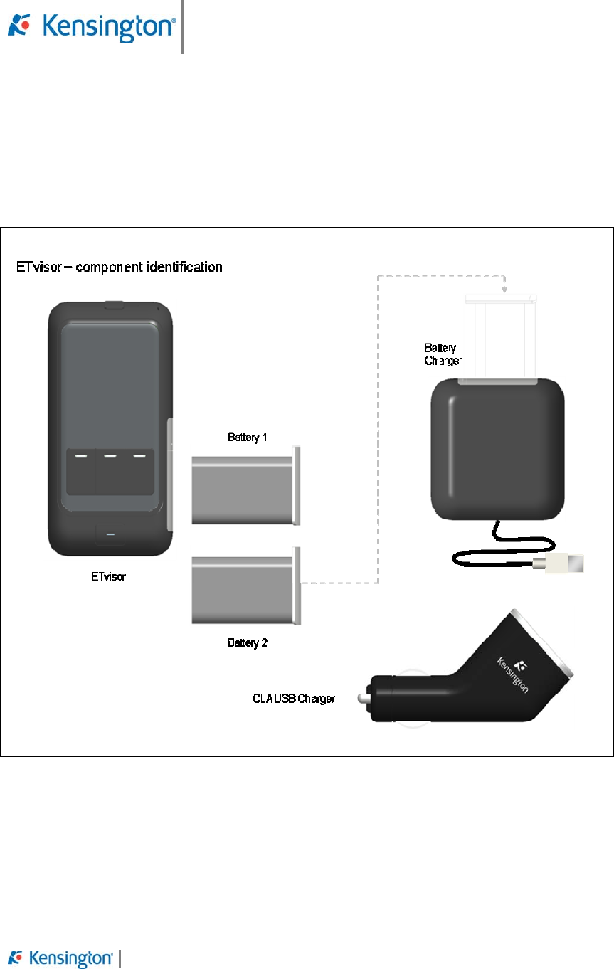
2.2 System Diagram
BT Visor Handsfree
Major components;
-BC05 BT Module
-NiMH Charging Circuitry
Product ships with two swappable battery packs
CLA USB Power adapter (Product K33410 Supplied by Everwin)
-iPhone charging circuitry
USB Powered Batter Charger
-NiMH charging circuitry
Product Engineering Specification
Document PES-K33440 Rev 0.8 March 27, 2008
Confidential Page 6 of 19
2.3 Button Functions
1. -Speed dial buttons: x 3
a. -When on a call, if the user presses & holds a speed dial button, the number for
that call is stored in memory.
b. -When not in a call, if the user briefly presses the speed dial button, that number
will be dialled by the cell phone and the call will be connected to the BT
handsfree kit.
c. If an incoming call is from one of the Speed dial numbers, the LED behind the
speed dial button will flash.
d. These buttons can be used to answer an incoming call with a short single press.
2. -Call/Answer & -Call End (One button)
3. -Volume slider (rheostat)
4. -Power
5. -Pair / Driver Swap
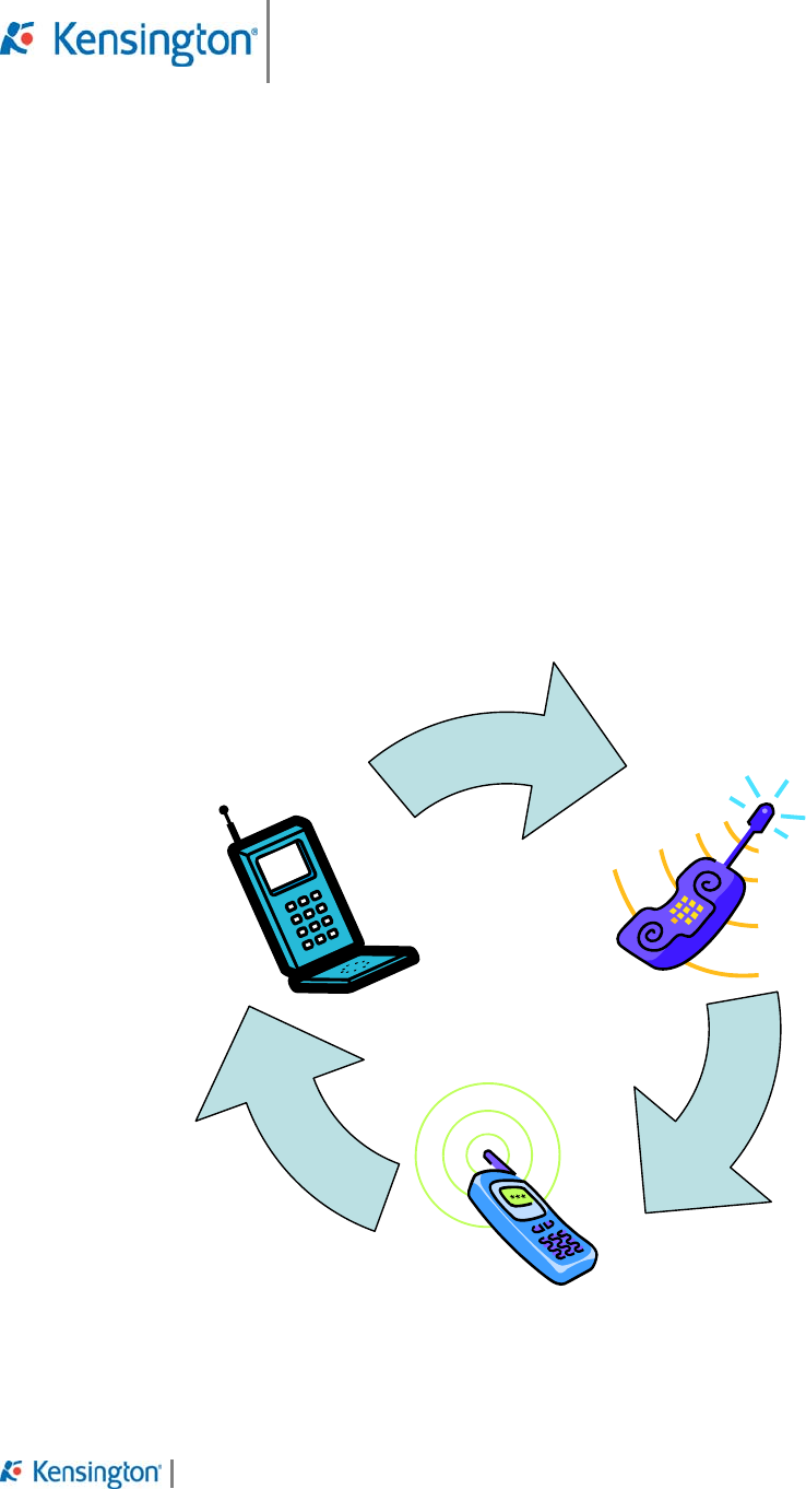
a. Press and hold to start pairing process with a new phone.
b. Quick press to disconnect from currently paired phone & attempt to reconnect
with the next phone in the buffer. Unit will be able to seamlessly cycle through
the 3 phones in memory.
See interface specification for more detailed description of button functions & actions.
Press BT/Swap Button
Press BT/Swap Button
Press BT/Swap Button
Product Engineering Specification
Document PES-K33440 Rev 0.8 March 27, 2008
Confidential Page 7 of 19
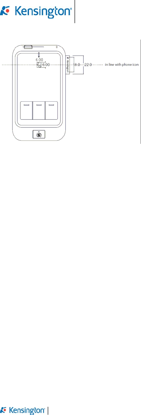
2.4 Display Functions
Indicators LED location shown below. Colour spec detailed in Interaction spec.
POWER LED HAS BEEN DELETED & FUNCTIONALITY HAS BEEN MOVED TO A TWO
COLOUR LED AT THE PHONE ICON
LED Indicators Buttons & Interaction Points
Figure 2 – Interaction Key
2. Power
1. Volume
Slider
4. Talk/End
5. Presets
x3
3. BT Swap/
BT Pair
B LED
(two colour
Blue / Red)
C1 LED
A
1 LED
(two colour
yellow/blue)
C1 LED
C1 LED

Product Engineering Specification
Document PES-K33440 Rev 0.8 March 27, 2008
Confidential Page 8 of 19
3.0 Electrical Specifications
This product is a standard BT handsfree visor product with a few additional features.
3.1 General Description
Firmware is to be written to follow requirements of interaction spec with the smarts to store 3
individual presets for each paired phone.
For example, PhoneA presets could be different from PhoneB. The firmware will be smart
enough to remember the BT Phone ID and allocate the separate memory location for presets for
that phone. Therefore, there are actually 9 presets stored in the device.
Whenever a BT phone with an ID already listed in the device, it is moved to the top of the list and
the corresponded presets are loaded. When a phone ID not listed in the device is paired, the
memory location for the one on the bottom of the list will be used overwriting the old ID and
clearing all presets while moving the phone ID to the top of the list.
3.2 Interface Description
See in appendix
3.3 Power Requirements
Talk time: up to 6 hours
Standby time: up to 7 days.
Power provided by a user-replaceable NiMH battery 800mAh
Recharging circuitry for NiMH battery is included in CLA battery charger.
USB port on CLA charger must meet iPhone power requirements listed in 3.8
3.4 BT Requirements
Chipset: CSR BC05
BT 2.1
Paired devices limited to 3 phones. One at a time
3.5 Audio Requirements
• Audio Out: Speaker
o Power (minimum) : 1W continuous,1.5- 2W peak.
o Sensitivity (SPL): min 82 +/- 3dB
o Impedance: 8 Ohm +/- 15%
o Lowest resonant frequency [Fo]: 280 – 480 Hz
o Effective frequency Range (minimum): Fo – 10kHz
o THD < 5%
o Recommended speaker VECO P40DS08G-3-75ND
• Audio In: measurement method tbd
o Generally the intent is to filter out all external noise factors including but not
limited to:
• Road Noise
• Car Noise
• Wind Noise
• Tire Noise
• Echo

Product Engineering Specification
Document PES-K33440 Rev 0.8 March 27, 2008
Confidential Page 9 of 19
• Other ambient noises
o The prime audio solution (firmware based) for ET will be provided by Primax
o Echo rejection: >42 dB
o Convergence in presence of back ground noise: < 1.0 sec
o Noise Cancellation: 12 dB
o No Distortion or speech clipping
o Comfort noise injection for natural sounding conversations
o Enhanced Non-linear processor for suppression of residual echo
o Microphone:
• Omni directional microphone to be used
• To be isolated via a rubber “boot” to prevent vibration transmission
• Not to be rigidly mounted to the PCB, should be mounted to the plastics
and attached to the PCB via flying leads
• RF filtering a must to reduce TDMA noise issues
• 6mm diameter microphone to be used
• Microphone SNR to be min 55 dB
• The microphone is to be located on the front face plate for optimum user
orientation.
• Sensitivity greater than -45 dBV at 1KHz
• Reference Microphone:
• Kingstate Microphone with flying leads.
• KECC2244WBL-G9U
3.6 Recharging requirements.
Visor BT handsfree Product will ship along with:
- 2 rectangular NiMH battery packs with contacts (no flying leads)
- USB battery charger
-CLA – USB power adapter
3.7 Battery Pack Specifications
-Must meet 3.3 Power requirements
-Rectangular battery enclosed in plastic (user replaceable)
-Clean look. Shrink wrapped battery packs are not acceptable.
-800mAh
-NiMH Chemistry
3.8 USB Battery Charger:
-Includes NiMH charging circuit for Battery pack.
-Includes cavity to accept NiMH Battery Pack
3.9 CLA USB Power adapter Specifications:
-Plugs into 12V power socket of car
-Fused 2AMPS SMT Quick burn
-Includes USB Power circuit which meets the following iPhone 5V power requirements
(Kensington will provide proven reference design to meet these requirements:
In order to reduce PCB space an SMT type fuse it to be used, rated to 2 Amps.
Product Engineering Specification
Document PES-K33440 Rev 0.8 March 27, 2008
Confidential Page 10 of 19
• The CLA power supply for the USB shall meet the following technical requirements:
a. Input Surge
1. While the circuit is operating at MAX load and Min load the line
voltage is switched to the surge voltage
a. 12Vdc to 40Vdc for 16msec, back to 12Vdc. Repeated 5
times at 50% duty cycle
2. There shall be no component damage, Voltage / logic signals
shall remain within specified limits, No loss of performance and
no permanent damage.
b. Identity line Signals (USB)
1. With no load on the circuit measure the voltages on D+ and D-
2. The voltage must fall within the below limits
a. D+ : 1.91V to 2.12V
b. D-: 1.91V to 2.12V
c. Load / Line / Regulation
1. While the load on one output is increased in steps to a
predetermined table, the output voltage deviations are noted.
Test is repeated for different input voltages
2. Output Voltage range
a. Vmin=4.85v
b. Vnom=5.0v
c. Vmax=5.25v
Regulation (V)
Input Voltage
(Vdc) 0.0A 0.25A 0.50A 0.70A 1.0A
10V Na Na
12V Na Na
14V Na Na
d. Dynamic Line Response
1. The PSU is subject to a +2Vdc line variation. The output loads
are chosen to give the worst case condition. No load capacitors
shall be used.
2. The PSU should not undershoot or overshoot beyond the
regulation limits (4.85Vmin, 5.25 Vmax)
e. Turn off/on Characteristics
1. All timing are to measured with a 5uF capacitive loading and 12V
DC input voltage.
a. Turn-on delay after DC input applied: T1<4.0 sec at
which point the output voltage must have stabilized
between 4.85 and 5.25 V DC.
b. Output rise time (10% to 90% regulation): T2 <20ms
2. All parameters must be within specification
a. The output voltage overshoot upon the application or
removal of the input voltage shall be less than 10%
above the nominal voltage.
b. There must be a smooth and continuous ramp of the DC
output voltage from 10% to 90% of its final set point
within the regulation band, while loaded as specified in

Product Engineering Specification
Document PES-K33440 Rev 0.8 March 27, 2008
Confidential Page 11 of 19
section 3.3.b. No voltage of opposite polarity shall be
present on any output during turn-on or turn off.
f. Fuse Protection
1. A fuse must be present at the input of the circuit so as to protect
the circuit under any fault condition.
g. Short Circuit
1. A short circuit is defined as less than 0.01 Ohm resistance
between the output terminals. The PSU is submitted to a short
circuit at minimum load
2. The output shall Hiccup or Foldback if any of the outputs are
shorted to the secondary common. No damage shall result.
Output shall recover after the short is removed.
h. Overcurrent:
1. The load is increased on one output from its maximum value to
an estimated over current value in several steps at a rate of 0.1
A/sec. The test is repeated at different input voltages.
2. Overload currents applied to each tested output rail will cause
the output to trip before they reach any point of damage to the
circuit. For testing purposes the overload currents should be
ramped at a minimum rate of 0.1 A/sec starting at full load.
3. The limit during overload condition also applies to any single
fault condition.
4.0 Mechanical Specifications
Describe product mechanical specifications in this section, such as product Industrial Design,
dimension, mechanical construction design, mechanical components design and assemble,
product housing, color and finish, and so on. 3D design images are preferred to show the details
of the design. You may add sub-sections as needed.
4.1 Industrial Design Considerations
-To be provided by Kensington in K33440 CMF document
-Product Branding (ET_logotag_033108.ai) – Stitched logo tag
Product Engineering Specification
Document PES-K33440 Rev 0.8 March 27, 2008
Confidential Page 12 of 19
4.2 Component and Assembly Specifications
-Recommended configuration to be provided by Kensington during on going discussion
between Kensington’s ME department and the supplier’s ME resource.
4.3 Bill of Materials
For a detailed Bill of Materials refer to the document BOM-K33440-REV_A
4.4 Material Specifications
See CMF
4.5 Tooling Specifications
4.6 Compliance and Recycling Requirements
4.7 Product Labelling Requirements
- Regulatory info will be pad printed on the rear of the product.

Product Engineering Specification
Document PES-K33440 Rev 0.8 March 27, 2008
Confidential Page 13 of 19
5.0 Software Specifications
5.1 General Specifications
N/A
5.2 Compatibility Requirements
Mobile phones supporting Bluetooth 1.2 specification and Handsfree or Headset profiles.
5.3 Installation Requirements
N/A
Product Engineering Specification
Document PES-K33440 Rev 0.8 March 27, 2008
Confidential Page 14 of 19
6.0 Product Packaging, Labelling and Documentation
Describe product packaging, labelling and documentation requirement in this section. You may
add sub-sections as needed. In this section, you may need to specify the specifications for
packaging material, provide the BOM of the packaging and photos or drawing of the assembly
components of the packaging. You may also need to specify the requirement of using Kensington
Logo and product labels on packaging.
6.1 Packaging Name
6.2 Box Structure Materials Specifications
6.3 Bill of Materials of Packaging
6.4 Sample Photo of Prior Design
K33408.ppt
.
6.5 Sample Photo and/or Drawing of ALL die cut components
Insert photos and/or drawings here.
6.6 Sample Photo and/or Drawing of Assembly of all Component parts
Insert photos and/or drawings here.
Product Engineering Specification
Document PES-K33440 Rev 0.8 March 27, 2008
Confidential Page 15 of 19
7.0 Environmental Specifications
This product shall comply with, at least but not limited, the environmental specifications selected
in this section.
Please refer to the reference b) which is the “KTG-QA-G005-xx – Kensington Environmental Test
Specification” document for the details of each test case. The ‘xx’ here means the latest revision
of this document.
For this product the temperature range will be -20’C - +60’C
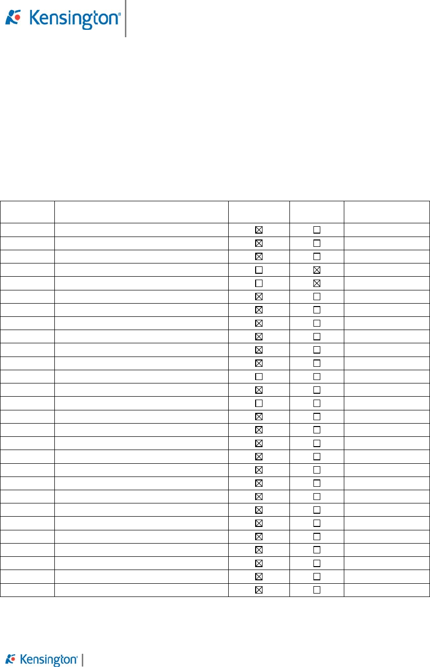
Environmental test cases selection table
Test
Case No. Test Case Name Mandatory
Test Optional
Test Comments
1 Drop test without package
2 Drop test with package
3 Vibration test without package
4 Vibration test with package
5 Shock without package
6 High temperature (operating) test
7 Low temperature (operating) test
8 Thermal shock test
9 High temperature (storage) test
10 Low temperature (storage) test
11 Humidity cycling (storage) test
12 Switch life cycle test
13 Key/Button life cycle test
14 Scroll Wheel life cycle test
15 Battery cover/door endurance test
16 Insert parts endurance test
17 Cable bending strength test
18 Cable pull strength test
19 Cable and part joint strength test
20 Paint surface chemical resistance test
21 Paint surface abrasion test
22 Paint surface adhesive ability test
23 Surge voltage test
24 Supply voltage fluctuation test
25 Reverse voltage test
26 ESD test (Direct Discharge)
27 ESD test (Indirect Discharge)
28 ESD test (Actual Use)
Note:
- Mandatory Test: tests must be conducted on this product.
- Optional Test: tests are optional to this product.
Product Engineering Specification
Document PES-K33440 Rev 0.8 March 27, 2008
Confidential Page 16 of 19
8.0 Regulatory Requirements
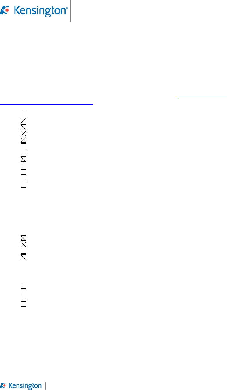
8.1 Region Regulatory Requirements
Product manager shall select the corresponding marketing area for this product to insure that
region regulatory compliance requirements are met for the following target markets.
Project managers shall request contract manufacturers to complete the Product Compliance
Certification Summary KTG-QA-S001 by the end of the final design stage.
Africa - List countries:_______
Asia - List countries:_Hong Kong, Japan, Malaysia, Singapore
Australia
Canada
Europe - All European Union countries requiring CE mark
Europe – Other Non European Union countries - List countries:______
South America - List countries:______
USA
Mexico
Middle East - List countries:_______
Russia
Other countries:________
8.2 Environmental & Energy Compliance Requirements
Please select from the following list for the Environmental & Energy Compliance required for this
product. If there is other requirement, please add description below.
RoHS Directive 2002/95/EC (Europe)
WEEE Directive 2002/96/EC (Europe)
Energy Star (USA)
Lead-Free (USA)
8.3 OEM Specific Requirements
Dell Specific Requirements
HP Specific Requirements
Apple Specific Requirements
Other, please specify …

Product Engineering Specification
Document PES-K33440 Rev 0.8 March 27, 2008
Confidential Page 17 of 19
9.0 Quality Requirements
Please describe the quality requirement for this product below. The example subsections are
given as a reference. Author may change these subsections or add more requirements according
to the corresponding product.
9.1 Design Workload
This product is designed to be capable of operating 24 hours a day, 365 days a year under the
specified environmental conditions defined in section 7.1 and 7.2.
9.2 Reliability Requirements
The reliability of this product shall be measured by MTBF (mean time between failures). It is the
average time that this product is being used under its specific operating conditions before a
failure occurs since last failure happened. It is measured in hours.
The MTBF of this product is > ?????? hours.
Note: The MTBF value is related to product design and manufacturing. It can be estimated based
on the life accelerated tests. So when the product is in pre-production phase, the product life
accelerated tests must be applied to ensure the required MTBF value is achievable.
9.3 Acceptance Quality Level
The MIL-STD-105E shall be used as the standard of making the random sampling inspections for
product manufacturing. The minimum Acceptance Quality Level for this product is defined as
following:
Critical defects: no critical defect is acceptable
Major defects: AQL
Minor defects: AQL
The author should define the AQL value based on the product characteristics.
Defects Classification:
Critical: likely to result in unsafe condition or contravene mandatory regulation (no critical defect is
accepted).
Major: reduces the usability of the product or is an obvious appearance defect.
Minor: doesn’t reduce the usability of the product, but is a defect beyond the defined quality
standard.
The author can define these three types of defects in more detailed if it is necessary.
Product Engineering Specification
Document PES-K33440 Rev 0.8 March 27, 2008
Confidential Page 18 of 19
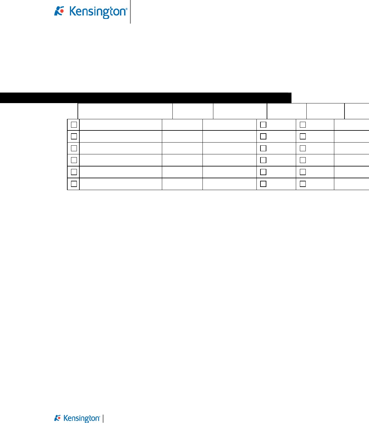
10.0 Approval
After this document has been reviewed by all related manager and engineers listed below, and
the document has been refined based on review comments, this document should be signed and
approved by all required approvers.
Approvals
Department Approval
required if checked Name Signature Approved Rejected* Dat
e
Project Manager
Product Manager
Operation Manager
Product Development
Senior Design Engineer
Quality Assurance
* If someone rejected the approval, please describe the reason here.
Federal Communication Commission Interference
Statement
This equipment has been tested and found to comply with the limits for a Class B
digital device, pursuant to Part 15 of the FCC Rules. These limits are designed
to provide reasonable protection against harmful interference in a residential
installation. This equipment generates, uses and can radiate radio frequency
energy and, if not installed and used in accordance with the instructions, may
cause harmful interference to radio communications. However, there is no
guarantee that interference will not occur in a particular installation. If this
equipment does cause harmful interference to radio or television reception, which
can be determined by turning the equipment off and on, the user is encouraged
to try to correct the interference by one of the following measures:
Reorient or relocate the receiving antenna.
Increase the separation between the equipment and receiver.
Connect the equipment into an outlet on a circuit different from that to which
the receiver is connected.
Consult the dealer or an experienced radio/TV technician for help.

Product Engineering Specification
Document PES-K33440 Rev 0.8 March 27, 2008
Confidential Page 19 of 19
FCC Caution: Any changes or modifications not expressly approved by the party
responsible for compliance could void the user's authority to operate this
equipment.
This device complies with Part 15 of the FCC Rules. Operation is subject to the
following two conditions: (1) This device may not cause harmful interference, and
(2) this device must accept any interference received, including interference that
may cause undesired operation.
This device and its antenna(s) must not be co-located or operating in conjunction
with any other antenna or transmitter.