ACD Elektronik X1310TC915 radio module for data transmission User Manual Integration Manual
ACD Elektronik GmbH radio module for data transmission Integration Manual
Integration Manual
160701-AU01_Operating_instructions _V1.4_en.doc 1 / 13
Integration manual
Operating instructions X1310 ISM
Transceiver - 915MHz
Version: 1.4
© Copyright ACD Gruppe
This document may not be duplicated or made accessible to
third parties without permission.

160701-AU01_Operating_instructions _V1.4_en.doc 2 / 13
Contents
1 Scope of delivery .......................................................................................... 3
2 Intended use ................................................................................................ 3
3 Handling ....................................................................................................... 4
4 Installation of the components ...................................................................... 4
4.1 Example for installation ............................................................................................. 4
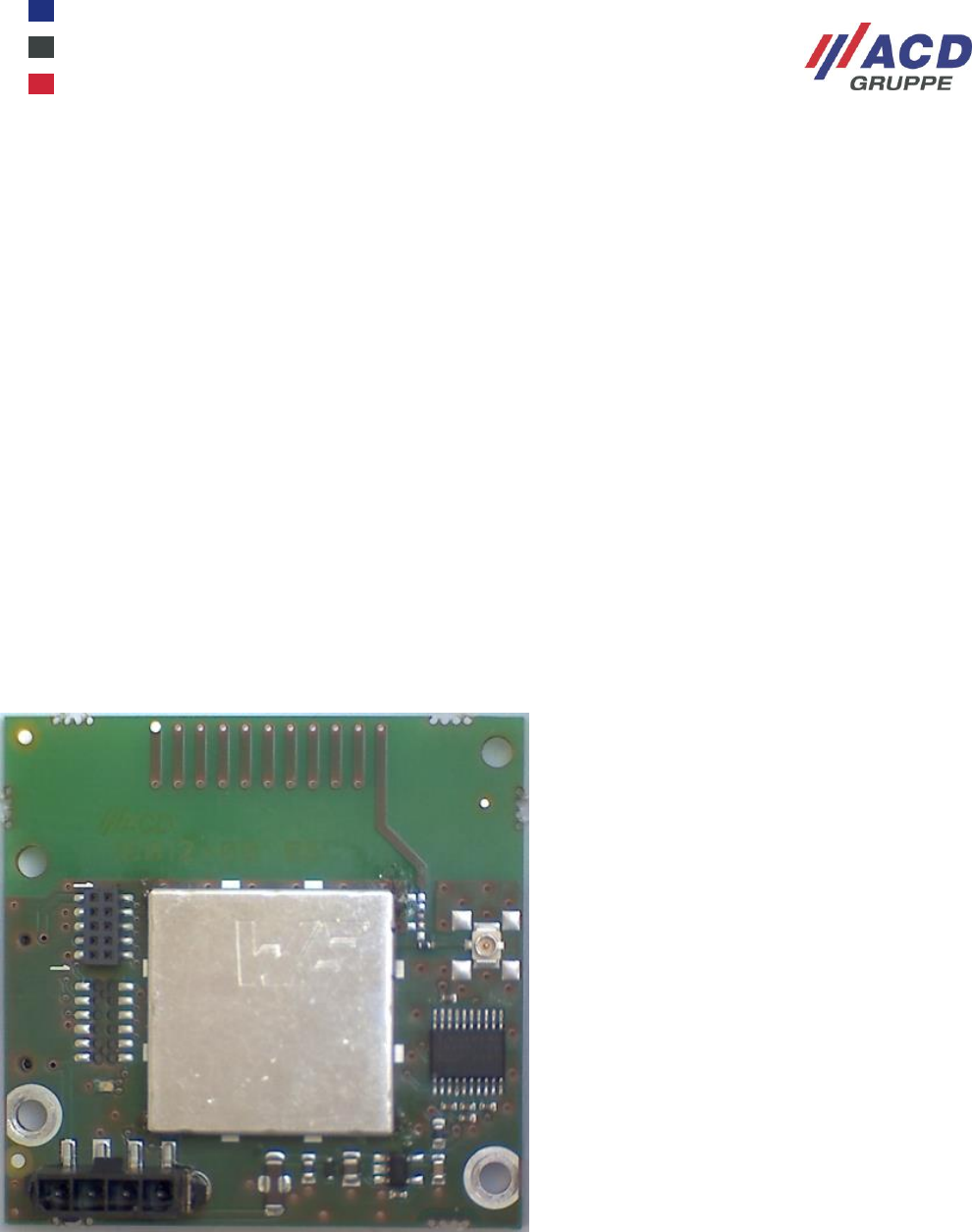
5 Module description ....................................................................................... 5
5.1 Introduction ............................................................................................................... 5
5.1.1 Printed circuit board/module ................................................................................ 5
5.1.2 Environmental conditions ..................................................................................... 5
5.1.3 System ................................................................................................................. 5
5.2 Assembling the PCB module .................................................................................... 5
5.3 Pin assignment and designation ............................................................................... 6
5.3.1 X1 connector assignment (host interface) ........................................................... 6
5.3.2 X2 connector assignment (host interface) ........................................................... 6
5.3.3 X4 connector (HF cable/antenna connection) ..................................................... 6
5.3.4 HF cable ............................................................................................................... 6
5.4 Antennas ................................................................................................................... 6
6 Functional description .................................................................................. 7
6.1 Control commands and telegrams ............................................................................ 7
6.2 Control commands in command mode ..................................................................... 7
6.3 Control commands in data mode .............................................................................. 8
6.4 Data telegram ............................................................................................................ 8
6.5 Acknowledgement telegram ...................................................................................... 8
7 USA/Canada frequency table 915MHz ......................................................... 9
8 Service and spare parts ............................................................................. 10
9 RSS COMPLIANCE STATEMENT ............................................................. 11
10 End device labeling instructions ................................................................. 11
Author:
S. Maier
/
17.02.02
160701-AU01_Operating_instructions _V1.4_en.doc 3 / 13
1 Scope of delivery
Module
HF cable
Antenna
Check that all components are undamaged and that all package contents are present
2 Intended use
The “X1310-ISM-Transceiver-915MHz” module is a radio module for data transmission in the ISM band
(SUB-GHz range) with the transceiver assembly CC1310 from TI. This module is intended for the frequency
range 902.000 – 928.00MHz.
Do not use the system in explosive areas.
Please observe all national regulatory requirements for wireless devices.
The supplied components are intended exclusively for use with this module.
NOTE
This device complies with Part 15 of the FCC Rules. Operation is
subject to the following two conditions:
(1) This device may not cause harmful interference, and
(2) This device must accept any interference received, including
interference that may cause undesired operation.
NOTE
Changes or modifications not expressly approved by the party
responsible for compliance could void the user’s authority to
operate the equipment.
NOTE
This device complies with Industry Canada’s licence-exempt
RSSs. Operation is subject to the following two conditions:
(1) This device may not cause interference; and
(2) This device must accept any interference, including
interference that may cause undesired operation of the device
NOTE
Le présent appareil est conforme aux CNR d’Industrie Canada
applicables aux appareils radio exempts de licence. L’exploitation
est autorisée aux deux conditions suivantes :
1) l’appareil ne doit pas produire de brouillage;
2) l’utilisateur de l’appareil doit accepter tout brouillage
radioélectrique subi, même si le brouil-lage est susceptible d’en
compromettre le fonctionnement.
160701-AU01_Operating_instructions _V1.4_en.doc 4 / 13
3 Handling
Read all instructions first before using the module!
Do not drink any alcohol or take any drugs while using the module
and follow the saftey instructions carefully!
ATTENTION
The utilization of non-approved components can lead to the
destruction of the device.
4 Installation of the components
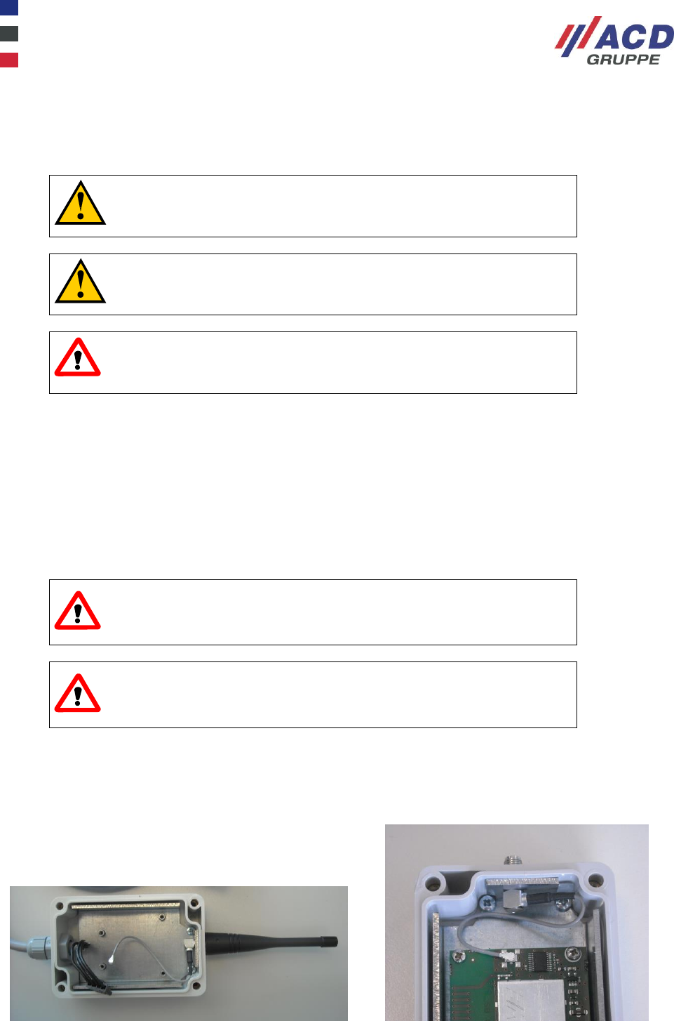
The printed circuit board is attached to the four fixing holes in the application.
The associated HF cable (length 100mm) is fixed to the application housing using the SMA socket and the
associated fixing nut. One of the approved antennas (see Chap 5.4) is screwed onto the SMA socket.
The HF cable’s U.FL connector is inserted onto the X4 connector on the printed circuit board.
The printed circuit board is connected to the host system via the X1 or X2 connector.
ATTENTION
Unintended use of the interfaces should be avoided.
ATTENTION
All components must be disposed of properly at the end of their
technical lifetime.
4.1 Example for installation
The SMA connector has to be mounted on top of a ground plane. The antenna has to be mounted on the
SMA connector.
160701-AU01_Operating_instructions _V1.4_en.doc 5 / 13
5 Module description
5.1 Introduction
The “X1310-ISM-Transceiver-915MHz” module is a radio module for data transmission in the ISM band
(SUB-GHz range) with the transceiver assembly CC1310 from TI. This module is intended for the frequency
range 902.000 – 928.00MHz.
5.1.1 Printed circuit board/module
Printed circuit board material
FR4
HF socket
U.FL (MCX)
Interface
RS232 (X1 / 4-pin); (X2 / 12-pin)
Internal status indicator
1 LED red/green (not assembled)
External status indicator
2 TTL outputs (transmit/receive)
Printed circuit board dimensions
46.23 x 45.47 x 15 mm (LxWxH)
Fixing
4 bore holes
Weight
Approx. 50 g
5.1.2 Environmental conditions
Air humidity
0% – 95%, not condensing
Operation temperature range
-30 °C to +70 °C
Storage temperature
-30 °C to +85°C
5.1.3 System
Transceiver type/MCU
CC1310 ARM Cortex-M3 (TI)
Firmware/radio protocol
Proprietary ACD radio protocol
Memory integrated
64kB Flash (up to 128k possible)
Interface
RS232; RxD, TxD, RTS, CTS
Internal status indicator
1 LED red/green (not assembled)
External status indicator
2 TTL outputs (transmit/receive)
HF output power
Approx. -10dBm to -12dBm
Sensitivity/transmission rate
-110dBm / 19.2kBaud
Modulation
GFSK
Power supply
+4 to +15Vdc, typ. 12mA (<25mA)
Approvals
USA/Canada FCC15.249.a; FCC-ID
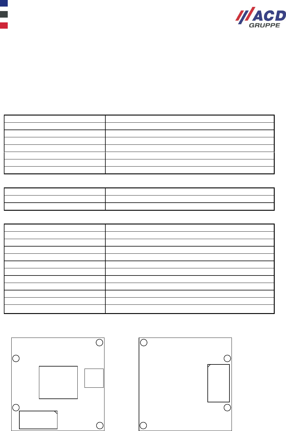
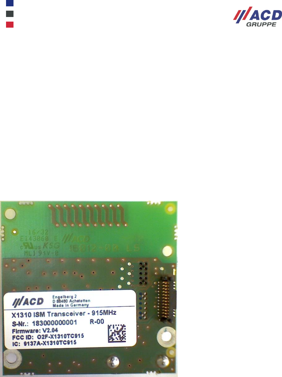
5.2 Assembling the PCB module
Assembling on the component side Assembling on the solder side
Shielding
cabinet
Connector
X1
Conne
ctor
X4
Connector
X2
160701-AU01_Operating_instructions _V1.4_en.doc 6 / 13
5.3 Pin assignment and designation
5.3.1 X1 connector assignment (host interface)
Connector: 2-1445052-4 TE connectivity
Suitable mating connector: MOLEX 43645-0400 (connector ) or suitable alternatives
MOLEX 43030-001 (crimp contacts)
Pin number
Description
1
TxD (RS232)
2
RxD (RS232)
3
GND
4
+12V
5.3.2 X2 connector assignment (host interface)
Connector: 114712 Erni
Suitable mating connector: 114712 Erni
Pin number
Description
1
+3.3V
2
nc
3
LED_RX
4
LED_TX
5
nc
6
RTS (RS232)
7
TxD (RS232)
8
Nc
9
GND
10
CTS (RS232)
11
RxD (RS232)
12
+12V
5.3.3 X4 connector (HF cable/antenna connection)
Connector: U.FL-R-SMT(01) Hirose or 73412-0110 Molex
5.3.4 HF cable
HF cable: K-2439-02 IMS Connector Systems or suitable alternatives
5.4 Antennas
The transceiver may only be operated with the two antennas listed below, as this would otherwise not
comply with the approval!
Antenna 1: CTA 915/0/WS/SM/H1 COMPOTEK
or
Antenna 2: CTA 920/0/WR/SM/W1 COMPOTEK

160701-AU01_Operating_instructions _V1.4_en.doc 7 / 13
6 Functional description
The data to be sent is transmitted from the host via the RS232 interface to the “X1310-ISM-Transceiver-
915MHz” module and then GFSK modulated and transmitted by this module via the transmission level and
antenna to a receiver module of the same type.
This module is intended for the frequency range 902.000 – 928.00MHz.
The frequency range is divided into 32 channels with a respective channel spacing of 750KHz
(see Chap.7: USA/Canada frequency table 915MHz).
The module can be configured via the RS232 interface using commands
(see Chap. 6.2: Control commands in command mode, or Chap. 6.3: Control commands in data mode).
6.1 Control commands and telegrams
Firstly, a common frequency from the frequency table in Chap. 7 is defined for all radio devices.
The host checks whether the radio channel is available (LBT, Listen Before Talk). If this condition is met,
data or acknowledgement telegrams are transmitted, after a random delay, via the RS232 interface to the
X1310 transceiver, starting with an <STX>, followed by the <Data> and ending with an <ETB>. Based on the
<STX> received, the transceiver now switches on the HF carrier and, first of all, transmits a preamble and
SYNC sign. The sequence previously received via the interface is then sent <STX>, <Data>, <ETB>. The
<ETB> switches the HF carrier off again in the end.
The length of a telegram is limited by the settable transmission timeout (see “Control commands in command
mode” table under STO1..99) in order to not block the remaining infrastructure.
The function is as follows on the receiving side: The receiver in X1310 continuously searches for the SYNC
signs. If detected, the data received below is transmitted via the RS232 interface to the host up to the
<ETB>. If determined that the HF carrier is interrupted, the receipt is also terminated.
The RF signal is GFSK modulated with a frequency deviation of ±14 kHz and a data rate of 19.2 kbit/s. The
modulation parameters are fully determined by the internal register settings of the CC1310 radio IC and are
independent on the signal at the interface.
Together with the antennas listed in the user manual (5.4), the transmission power is below the limits given
under §15.249 of CFR47.
6.2 Control commands in command mode
After a reset, the set baud rate is output on the interface at 38400,N,8,1.
You can enable command mode using the sequence +++.
Command word
(Version firmware 2.01)
SWV?
Returns the module’s firmware version.
KAN?
Channel query. Returns the set radio channel (default
K16).
KAN1..32
Channel setting. Sets the desired radio channel.
SDL?
Transmission power query
SDL1..31
Transmission power setting (dummy command), no
change due to compatibility matters.
RES
Reset radio module.
BDC?
COM baud rate query. Returned value is the set baud rate
(default 38.4).
BDC1.2,2.4,4.8,9.6,19.2,38.4,57.6
Setting the COM baud rate. Example: BDC38.4 sets the
baud rate to 38400,N,8,1 (default)
BDF?
Radio baud rate query. (default 19.2k).
BDF1.2,2.4,4.8,9.6,19.2,38.4,57.6
Setting the radio baud rate (dummy command), no
change due to compatibility matters.
DEF
Setting the default values. Returned value OK.
DEF?
Displaying the default values.
160701-AU01_Operating_instructions _V1.4_en.doc 8 / 13
CFG?
Displaying the configuration
FSM0..1
Field strength measurement. FSM0: Field strength
measurement off. FSM1: Field strength measurement on.
FSM?
Query whether field strength measurement is on or off.
STO1..99
Setting the transmission timeout in 100ms steps.
(default 3s / max.9.9s)
STO?
Returns the set transmission timeout.
RSP0..9
Setting the squelch.
RSP?
Returns the set squelch.
SAV
Saving the setting.
HELP
List of the command words
EXIT
Leave command mode.
Command mode is left after a timeout (1min).
6.3 Control commands in data mode
The configuration can also be performed in data mode using control telegrams.
<SOH><Command word><Command word><EOT>.
Example: Channel query
<SOH>KAN?<EOT> return: <SOH>KAN8<EOT>
Example: Set channel to channel 12:
<SOH>KAN12<EOT> return: <SOH>KAN12<EOT>
6.4 Data telegram
LBT applies (Listen Before Talk).
<STX><Header><Data><ETB>
STX switches the transmitter on
ETB switches the transmitter off
6.5 Acknowledgement telegram
A data telegram is acknowledged by an acknowledgement telegram.
LBT applies (Listen Before Talk).
<STX><Header><Acknowledgement><ETB>
STX switches the transmitter on
ETB switches the transmitter off

160701-AU01_Operating_instructions _V1.4_en.doc 9 / 13
7 USA/Canada frequency table 915MHz
Channels 32
Channel spacing: 750KHz.
Transmission power
SDLx dBm Power μW/mW
Channel 1: 903.500MHz
Channel 2: 904.250MHz
Channel 3: 905.000MHz
Channel 4: 905.750MHz
Channel 5: 906.500MHz
Channel 6: 907.250MHz
Channel 7: 908.000MHz
Channel 8: 908.750MHz
Channel 9: 909.500MHz
Channel 10: 910.250MHz
Channel 11: 911.000MHz
Channel 12: 911.750MHz
Channel 13: 912.500MHz
Channel 14: 913.250MHz
Channel 15: 914.000MHz
Channel 16: 914.750MHz (def.)
Channel 17: 915.500MHz
Channel 18: 916.250MHz
Channel 19: 917.000MHz
Channel 20: 917.750MHz
Channel 21: 918.500MHz
Channel 22: 919.250MHz
Channel 23: 920.000MHz
Channel 24: 920.750MHz
Channel 25: 921.500MHz
Channel 26: 922.250MHz
Channel 27: 923.000MHz
Channel 28: 923.750MHz
Channel 29: 924.500MHz
Channel 30: 925.250MHz
Channel 31: 926.000MHz
Channel 32: 926.750MHz
1 -12dBm 63μW (def.)
2 -12dBm 63μW
3 -12dBm 63μW
4 -12dBm 63μW
5 -12dBm 63μW
6 -12dBm 63μW
7 -12dBm 63μW
8 -12dBm 63μW
9 -12dBm 63μW
10 -12dBm 63μW
11 -12dBm 63μW
12 -12dBm 63μW
13 -12dBm 63μW
14 -12dBm 63μW
15 -12dBm 63μW
16 -12dBm 63μW
17 -12dBm 63μW
18 -12dBm 63μW
19 -12dBm 63μW
20 -12dBm 63μW
21 -12dBm 63μW
22 -12dBm 63μW
23 -12dBm 63μW
24 -12dBm 63μW
25 -12dBm 63μW
26 -12dBm 63μW
27 -12dBm 63μW
28 -12dBm 63μW
29 -12dBm 63μW
30 -12dBm 63μW
31 -12dBm 63μW
Frequency band: 902.000 – 928.00MHz
Transmission power: approx.-12dBm
Channel raster: 750 kHz
Duty cycle: no limits
160701-AU01_Operating_instructions _V1.4_en.doc 10 / 13
8 Service and spare parts
If you have service requests, or require spare parts, please contact:
ACD Elektronik GmbH
Engelberg 2
88480 Achstetten
Germany
Telephone: +49 7392 708 499
Fax: +49 7392 708 490
Email: info@acd-elektronik.de
Use original spare parts only.
160701-AU01_Operating_instructions _V1.4_en.doc 11 / 13
9 RSS COMPLIANCE STATEMENT
This device complies with Industry Canada’s licence-exempt RSSs. Operation is subject to the following two
conditions:
(1) This device may not cause interference; and
(2) This device must accept any interference, including interference that may cause undesired operation of
the device
Le présent appareil est conforme aux CNR d’Industrie Canada applicables aux appareils radio exempts de
licence. L’exploitation est autorisée aux deux conditions suivantes :
1) l’appareil ne doit pas produire de brouillage;
2) l’utilisateur de l’appareil doit accepter tout brouillage radioélectrique subi, même si le brouil-lage est
susceptible d’en compromettre le fonctionnement.
10 End device labeling instructions
FCC notes for all hosts devices. The end device must be labeled with:
Contains FCC ID: O2F-X1310TC915“
Contains IC: 9137A-X1310TC915
Labelling Requirements
In addition following statement shall be placed on the device:

160701-AU01_Operating_instructions _V1.4_en.doc 12 / 13
This device complies with Part 15 of the FCC Rules. Operation is subject to the following two conditions:
(1) this device may not cause harmful interference, and (2) this device must accept any interference
received, including interference that may cause undesired operation.
Where the product is so small or for such use that it is not practicable to place the statement on it, the
statement can be placed in a prominent location in the instruction manual.
Information to the user
- For Class A devices the manual of the host shall include the following statement:
NOTE: This equipment has been tested and found to comply with the limits for a Class A digital device,
pursuant to part 15 of the FCC Rules. These limits are designed to provide reasonable protection against
harmful interference when the equipment is operated in a commercial environment. This equipment
generates, uses, and can radiate radio frequency energy and, if not installed and used in accordance with
the instruction manual, may cause harmful interference to radio communications. Operation of this
equipment in a residential area is likely to cause harmful interference in which case the user will be
required to correct the interference at his own expense.
- For Class B devices the manual of the host shall include the following statement:
Note: This equipment has been tested and found to comply with the limits for a Class B digital device,
pursuant to part 15 of the FCC Rules. These limits are designed to provide reason-able protection against
harmful interference in a residential installation. This equipment generates, uses and can radiate radio
frequency energy and, if not installed and used in accordance with the instructions, may cause harmful
interference to radio communications. However, there is no guarantee that interference will not occur in a
particular installation. If this equipment does cause harmful interference to radio or television reception,
which can be deter-mined by turning the equipment off and on, the user is encouraged to try to correct the
interference by one or more of the following measures:
--Reorient or relocate the receiving antenna.
--Increase the separation between the equipment and receiver.
--Connect the equipment into an outlet on a circuit different from that to which the receiver is connected.
--Consult the dealer or an experienced radio/TV technician for help.
Modification of equipment
The instruction manual of the host shall include the following statement: Changes or modifications made to
this equipment not expressly approved by the party responsible for compliance may void the FCC
authorization to operate this equipment.
Special accessories
Where special accessories such as shielded cables and/or special connectors are required to comply with
the emission limits, the instruction manual shall include appropriate instructions on the first page of the
text describing the installation of the device.
Final Compliance of end product
The integrator is responsible for the final compliance of the end product including this certified transmitter
module. CFR 47 §15.101 give guidance in terms of applicable equipment authorization procedures of
different end-products. Typically compliance to subpart 15 B (§15.107 and 15.109) Class A or B including
verification of the subpart 15 C compliance (field strength of fundamental and out-of-band emissions) of
the transmitter parameters apply.

160701-AU01_Operating_instructions _V1.4_en.doc 13 / 13
Simultaneous transmission
When the host product supports simultaneous-transmission operations the host manufacturer needs to
check if there are additional RF exposure filing requirements due to the simultaneous transmissions. When
additional application filing for RF exposure compliance demonstration is not required (e. g. if the X1310-
ISM-Transceiver-915MHz module in combination with all simultaneously operating transmitters complies
with the RF exposure simultaneous transmission SAR test exclusion requirements), the host manufacturer
may do his own evaluation without any filing, using reasonable engineering judgment and testing for
confirming compliance with out-of-band, restricted band, and spurious emission requirements in the
simultaneous-transmission operating modes.
If additional filing is required please contact the person at ACD Gruppe responsible for certification of the
X1310-ISM-Transceiver-915MHz module.