ACE&EASTMAN Rh 9820 Service Manual 9820SM_Cover1E User
2016-10-16
User Manual: ACE&EASTMAN Rh-9820 Service Manual
Open the PDF directly: View PDF ![]() .
.
Page Count: 236 [warning: Documents this large are best viewed by clicking the View PDF Link!]
- SAFETY INSTRUCTIONS
- 1. MACHINE SPECIFICATIONS
- 2. FUNCTION SETTINGS
- 3. READING/WRITING DATA
- 3-1. Precautions when handling CF cards (commercially available)
- 3-2. Structure of a CF card folder
- 3-3. Data read/write mode
- 3-4. Reading parameter data from the CF card
- 3-5. Writing parameter data to the CF card
- 3-6. Reading memory switch data from the CF card
- 3-7. Writing memory switch data to CF cards
- 3-8. Writing error log data to the CF card
- 3-9. Updating the main control program
- 3-10. Updating the panel control program
- 4. MECHANICAL DESCRIPTIONS
- 4-1. Upper shaft and Needle bar mechanisms
- 4-2. Zigzag and thread take-up mechanisms
- 4-3. Needle bar rocking mechanism
- 4-4. Feed mechanism
- 4-5. Presser foot mechanism
- 4-6. Cloth opening mechanism
- 4-7. Cutter mechanism
- 4-8. Looper mechanism
- 4-9. Spreader mechanism
- 4-10. Upper thread trimmer mechanism
- 4-11. Upper tension release mechanism
- 4-12. Upper thread take-up mechanism
- 4-13. Lower thread release and lower thread take-up mechanisms
- 4-14. Gimp thread take-up mechanism <-01 specifications only>
- 4-15. Lower thread trimmer mechanism
- 5. DISASSEMBLY
- 5-1. Covers and presser foot mechanism
- 5-2. Upper shaft motor unit mechanism
- 5-3. Feed mechanism
- 5-4. Lower thread tension mechanism
- 5-5. Spreader mechanism
- 5-6. Looper mechanism
- 5-7. Needle bar rocking mechanism
- 5-8. Looper base mechanism
- 5-9. Needle bar mechanism
- 5-10. Lubrication
- 5-11. Zigzag and thread take-up mechanisms
- 5-12. Upper shaft mechanism
- 5-13. Cutter mechanism
- 6. ASSEMBLY
- 6-1. Cutter mechanism
- 6-2. Needle bar mechanism (1)
- 6-3. Zigzag mechanism
- 6-4. Upper shaft mechanism
- 6-5. Thread take-up mechanism
- 6-6. Needle bar mechanism (2)
- 6-7. Y feed mechanism
- 6-8. Looper base mechanism
- 6-9. Needle bar rocking mechanism
- 6-10. Lower shaft mechanism
- 6-11. Looper mechanism
- 6-12. Spreader mechanism
- 6-13. Upper thread trimmer mechanism
- 6-14. Threading mechanism
- 6-15. Feed base mechanism
- 6-16. X feed mechanism
- 6-17. Lower thread tension mechanism
- 6-18. Upper shaft motor mechanism
- 6-19. Covers
- 6-20. Work clamp plate mechanism
- 6-21. Lower thread trimming mechanism
- 6-22. Upper cover mechanism (upper thread tension release and upper thread take-up mechanisms and upper thread path)
- 6-23. Routing the harnesses
- 6-24. Routing the air tubes
- 6-25. Lubrication and greasing and routing the oil tubes
- 7. ADJUSTMENTS
- 7-1. Adjusting the heights of the spreaders and loopers
- 7-2. Adjusting the zigzag width (stitch width)
- 7-3. Adjusting the zigzag base line position
- 7-4. Adjusting the needle and looper timing
- 7-5. Adjusting the looper stroke
- 7-6. Adjusting the height of the needle bar
- 7-7. Adjusting the clearance between the loopers and needle
- 7-8. Adjusting the needle guard
- 7-9. Adjusting the spreader installation positions
- 7-10. Adjusting the spreader timing
- 7-11. Adjusting the height of the throat plate
- 7-12. Changing the cutting length (Replacing the hammer)
- 7-13. Adjusting the cutting surface of the hammer
- 7-14. Adjusting the axial play of the hammer
- 7-15. Making the cutter driving shaft and driving shaft presser move together
- 7-16. Replacing the knife and adjusting its position
- 7-17. Adjusting the cutting pressure
- 7-18. Adjusting the work clamp lift amounts
- 7-19. Adjusting the work clamp positions
- 7-20. Adjusting the positions of the work clamp plates
- 7-21. Adjusting the cloth opening amounts
- 7-22. Adjusting the upper thread feeding amount
- 7-23. Adjusting the lower thread feeding amount <-01 specifications only>
- 7-24. Replacing and adjusting the upper movable knife
- 7-25. Replacing and adjusting the movable knife and fixed knife (for the lower thread and gimp) <-01 specifications>
- 7-26. Replacing and adjusting the movable knife and fixed knife (for the lower thread and gimp) <-02 specifications>
- 7-27. Adjusting the gimp trailing length <-02 specifications only>
- 7-28. Adjusting the position of the lower thread presser <-02 specifications only>
- 7-29. Adjustment of the phase for the take-up roller cam
- 7-30. Adjusting the needle bar and looper base turning center
- 7-31. Adjusting the upper thread loosening amount
- 7-32. Adjusting the lower thread loosening amount
- 7-33. Adjusting the looper base home position
- 7-34. Adjusting the feed base X home position and Y home position
- 7-35. Adjusting the needle up signal home position for the upper shaft and upper shaft motor
- 7-36. Adjusting the upper shaft stop position
- 7-37. Installing (replacing) the sub clamp on the left side
- 8. ELECTRICAL MECHANISM
- 9. ERROR CODES
- 10. TROUBLESHOOTING
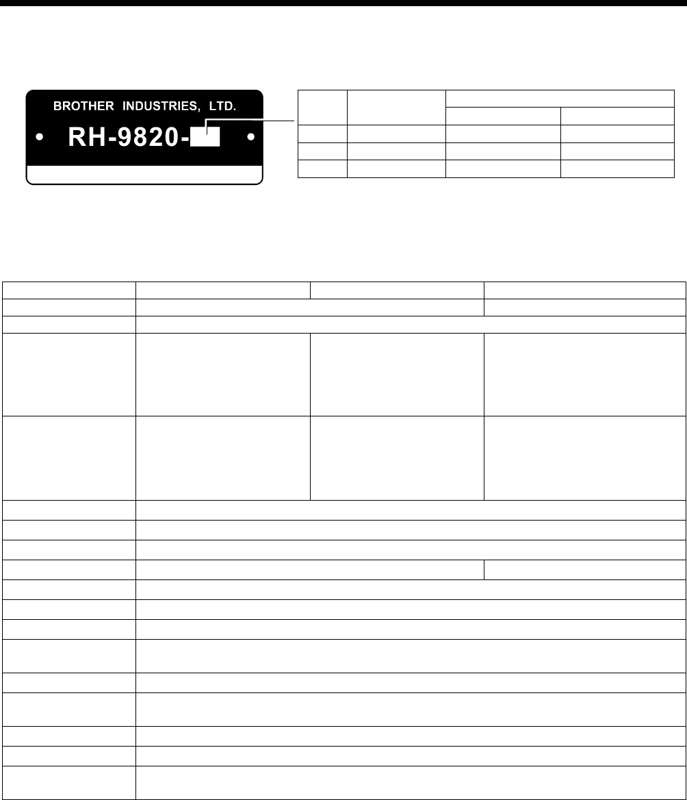
RH-9820
Please read this manual before making any adjustments.
ELECTRONIC EYELET BUTTON HOLER
SERVICE MANUAL
RH-9820
This service manual is intended for RH-9820; be sure to read the RH-9820 instruction manual before
this manual.
Carefully read the “SAFETY INSTRUCTIONS” and the whole of this manual to understand this product
before you start maintenance.
As a result of research and improvements regarding this product, some details of this manual may not
be the same as those for the product you purchased.
If you have any questions regarding this product, please contact a Brother dealer.

RH-9820 i
SAFETY INSTRUCTIONS
[1] Safety indications and their meanings
This service manual and the indications and symbols that are used on the machine itself are provided in order to ensure safe
operation of this machine and to prevent accidents and injury to yourself or other people.
The meanings of these indications and symbols are given below.
Indications
DANGER The instructions which follow this term indicate situations where failure to follow
the instructions will result in death or serious injury.
CAUTION The instructions which follow this term indicate situations where failure to follow
the instructions could cause injury when using the machine or physical damage
to equipment and surroundings.
Symbols
..……… This symbol ( ) indicates something that you should be careful of. The picture inside the triangle
indicates the nature of the caution that must be taken.
(For example, the symbol at left means “beware of injury”.)
..……… This symbol ( ) indicates something that you must not do.
..……… This symbol ( ) indicates something that you must do. The picture inside the circle indicates the
nature of the thing that must be done.
(For example, the symbol at left means “you must make the ground connection”.)
RH-9820
ii
[2] Notes on safety
DANGER
Wait at least 5 minutes after turning off the power switch and disconnecting the power cord from the wall outlet
before opening the cover of the control box. Touching areas where high voltages are present can result in severe
injury.
CAUTION
Environmental requirements
Use the sewing machine in an area which is free
from sources of strong electrical noise such as
electrical line noise or static electric noise.
Sources of strong electrical noise may cause
problems with correct operation.
Any fluctuations in the power supply voltage should
be within ±10% of the rated voltage for the machine.
Voltage fluctuations which are greater than this may
cause problems with correct operation.
The power supply capacity should be greater than
the requirements for the sewing machine's power
consumption.
Insufficient power supply capacity may cause
problems with correct operation.
The pneumatic delivery capability should be greater
than the requirements for the sewing machine's total
air consumption.
Insufficient pneumatic delivery capability may cause
problems with correct operation.
The ambient temperature should be within the range
of 5°C to 35°C during use.
Temperatures which are lower or higher than this
may cause problems with correct operation.
The relative humidity should be within the range of
45% to 85% during use, and no dew formation
should occur in any devices.
Excessively dry or humid environments and dew
formation may cause problems with correct
operation.
In the event of an electrical storm, turn off the power
and disconnect the power cord from the wall outlet.
Lightning may cause problems with correct
operation.
Installation
Machine installation should only be carried out by a
qualified technician.
Contact your Brother dealer or a qualified electrician
for any electrical work that may need to be done.
The sewing machine weighs approximately 120 kg.
Installation of the sewing machine and adjustment of
the table height should be carried out by four or
more people.
Do not connect the power cord until installation is
complete. If this is not done, the sewing machine
may operate if the start switch is pressed by mistake,
which could result in serious injury.
Hold the machine head with both hands when tilting
it back or returning it to its original position.
In addition, do not subject the machine head to extra
force while it is tilted back.
If this is not observed, the machine head may
become unbalanced and fall over (together with the
table), and serious injury or damage to the sewing
machine may result.
Be sure to connect the ground. If the ground
connection is not secure, you run a high risk of
receiving a serious electric shock, and problems with
correct operation may also occur.
All cords should be secured at least 25 mm away
from any moving parts. Furthermore, do not
excessively bend the cords or secure them too firmly
with staples.
If this is not observed, fire or electric shocks may
result.
Install belt covers to the machine head.
If using a work table which has casters, the casters
should be secured in such a way so that they cannot
move.
Be sure to wear protective goggles and gloves when
handling the lubricating oil, so that it does not get
into your eyes or onto your skin.
If care is not taken, inflammation can result.
Furthermore, do not drink the lubricating oil. Diarrhea
or vomiting may result.
Keep the oil out of the reach of children.
RH-9820 iii
CAUTION
Sewing
This sewing machine should only be used by
operators who have received the necessary training
in safe use beforehand.
The sewing machine should not be used for any
applications other than sewing.
Be sure to wear protective goggles when using the
machine.
If goggles are not worn, there is the danger that if a
needle breaks, parts of the broken needle may enter
your eyes and injury may result.
Turn off the power switch at the following times. If
this is not done, the sewing machine may operate if
the start switch is pressed by mistake, which could
result in serious injury.
• When threading the needle
• When replacing the needle
• When not using the machine and when leaving the
machine unattended
If using a work table which has casters, the casters
should be secured in such a way so that they cannot
move.
Attach all safety devices before using the sewing
machine. If the machine is used without these
devices attached, injury may result.
Do not touch any of the moving parts or press any
objects against the machine while sewing, as this
may result in personal injury or damage to the
machine.
If an error occurs in machine operation, or if
abnormal noises or smells are noticed, immediately
turn off the power switch. Then contact your nearest
Brother dealer or a qualified technician.
If the machine develops a problem, contact your
nearest Brother dealer or a qualified technician.
Cleaning
Turn off the power switch before carrying out this
operation. If this is not done, the sewing machine
may operate if the start switch is pressed by mistake,
which could result in serious injury.
Be sure to wear protective goggles and gloves when
handling the lubricating oil, so that it does not get into
your eyes or onto your skin.
If care is not taken, inflammation can result.
Furthermore, do not drink the lubricating oil. Diarrhea
or vomiting may result.
Keep the oil out of the reach of children.
Maintenance and inspection
Disassembly, assembly, maintenance and inspection
of the sewing machine should only be carried out by
a qualified technician.
Ask your Brother dealer or a qualified electrician to
carry out any maintenance and inspection of the
electrical system.
Turn off the power switch and disconnect the power
cord at the following times. If this is not done, the
sewing machine may operate if the start switch is
pressed by mistake, which could result in serious
injury.
• When carrying out inspection, adjustment and
maintenance
• When replacing consumable parts such as the
loopers and knife
Turn off the power switch before inserting or
removing the plug, otherwise damage to the control
box could result.
Disconnect the air hoses from the air supply and wait
for the needle on the pressure gauge to drop to “0”
before carrying out inspection, adjustment and repair
of any parts which use the pneumatic equipment.
If the power switch and air need to be left on when
carrying out some adjustment, be extremely careful
to observe all safety precautions.
Hold the machine head with both hands when tilting
it back or returning it to its original position.
In addition, do not subject the machine head to extra
force while it is tilted back.
If this is not observed, the machine head may
become unbalanced and fall over (together with the
table), and serious injury or damage to the sewing
machine may result.
Be sure to wear protective goggles and gloves when
handling the lubricating oil and grease, so that they
do not get into your eyes or onto your skin, otherwise
inflammation can result.
Furthermore, do not drink the oil or eat the grease
under any circumstances, as they can cause
vomiting and diarrhea.
Keep the oil out of the reach of children.
Use only the proper replacement parts as specified
by Brother.
If any safety devices have been removed, be
absolutely sure to re-install them to their original
positions and check that they operate correctly
before using the machine.
Any problems in machine operation which result
from unauthorized modifications to the machine will
not be covered by the warranty.
RH-9820
iv
[3] Warning labels
The following warning labels appear on the sewing machine.
Please follow the instructions on the labels at all times when using the machine. If the labels have been
removed or are difficult to read, please contact your nearest Brother dealer.
1 2
3 Do not touch the knife or press any
objects against the machine while
sewing, as this may result in personal
injury or damage to the machine.
Safety devices
Devices such as eye guard, finger guard,
needle bar guard, needle guide cover and
belt cover
4
Be careful not to get your hands
caught when returning the machine
head to its original position after it
has been tilted.
5 Be careful not to get your hands caught
when moving the feed base backward.
6 Be sure to connect the ground. If the
ground connection is not secure, you
run a high risk of receiving a serious
electric shock, and problems with
correct operation may also occur.
7 Direction of operation
8 High temperature warning display
Eye guard
Finger guard
Needle guide cove
r
Needle bar guard
0534B
0330B
0302B
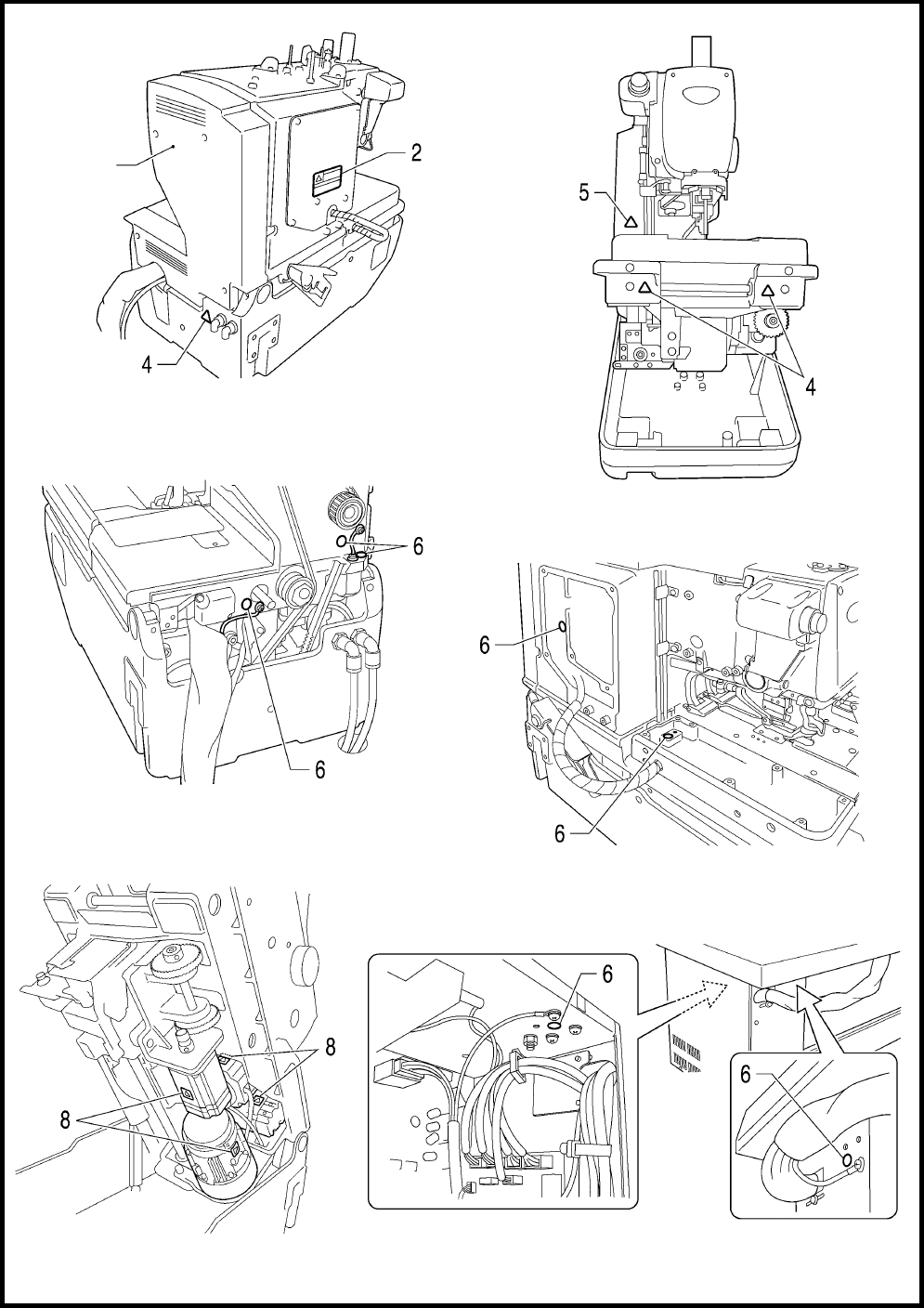
RH-9820 v
Belt cover
(Rear)
0331B
0332B
0334B
0486B
0485B
0333B

RH-9820
CONTENTS
1. MACHINE SPECIFICATIONS....... 1
2. FUNCTION SETTINGS ................. 2
2-1. List of special functions when power is turned on...............2
2-2. List of advanced functions..................................................... 3
2-3. Memory switch setting method (Advanced)........................4
2-4. List of memory switch settings..............................................5
2-5. Error history checking method............................................14
2-6. Input checking method ........................................................15
2-7. Output checking method .....................................................18
2-8. Software version checking method....................................21
3. READING/WRITING DATA ........ 22
3-1. Precautions when handling CF cards (commercially
available).............................................................................22
3-2. Structure of a CF card folder...............................................22
3-3. Data read/write mode ..........................................................23
3-4. Reading parameter data from the CF card .......................24
3-5. Writing parameter data to the CF card ..............................24
3-6. Reading memory switch data from the CF card...............24
3-7. Writing memory switch data to CF cards...........................24
3-8. Writing error log data to the CF card ..................................25
3-9. Updating the main control program....................................25
3-10. Updating the panel control program ................................25
4. MECHANICAL DESCRIPTIONS .. 26
4-1. Upper shaft and Needle bar mechanisms.........................26
4-2. Zigzag and thread take-up mechanisms ...........................27
4-3. Needle bar rocking mechanism..........................................28
4-4. Feed mechanism .................................................................29
4-5. Presser foot mechanism .....................................................30
4-6. Cloth opening mechanism ..................................................31
4-7. Cutter mechanism................................................................32
4-8. Looper mechanism..............................................................32
4-9. Spreader mechanism..........................................................33
4-10. Upper thread trimmer mechanism ...................................33
4-11. Upper tension release mechanism..................................34
4-12. Upper thread take-up mechanism ...................................34
4-13. Lower thread release and lower thread take-up
mechanisms.......................................................................35
4-14. Gimp thread take-up mechanism
<-01 specifications only>...................................................35
4-15. Lower thread trimmer mechanism ...................................36
5. DISASSEMBLY........................... 38
5-1. Covers and presser foot mechanism.................................39
5-2. Upper shaft motor unit mechanism....................................40
5-3. Feed mechanism................................................................. 41
5-3-1. Feed base unit ..........................................................41
5-3-2. X feed unit..................................................................42
5-3-3. Y feed unit..................................................................42
5-4. Lower thread tension mechanism...................................... 43
5-5. Spreader mechanism..........................................................44
5-6. Looper mechanism.............................................................. 45
5-7. Needle bar rocking mechanism .........................................46
5-8. Looper base mechanism ....................................................47
5-9. Needle bar mechanism....................................................... 48
5-10. Lubrication .......................................................................... 49
5-11. Zigzag and thread take-up mechanisms......................... 51
5-12. Upper shaft mechanism.................................................... 52
5-13. Cutter mechanism .............................................................53
6. ASSEMBLY................................. 54
6-1. Cutter mechanism ............................................................... 55
6-2. Needle bar mechanism (1) .................................................57
6-3. Zigzag mechanism .............................................................. 59
6-4. Upper shaft mechanism...................................................... 61
6-5. Thread take-up mechanism................................................ 64
6-6. Needle bar mechanism (2) .................................................65
6-7. Y feed mechanism............................................................... 69
6-8. Looper base mechanism ....................................................73
6-9. Needle bar rocking mechanism .........................................79
6-10. Lower shaft mechanism.................................................... 85
6-11. Looper mechanism ........................................................... 90
6-12. Spreader mechanism........................................................92
6-13. Upper thread trimmer mechanism................................... 94
6-14. Threading mechanism ......................................................95
6-15. Feed base mechanism .....................................................97
6-15-1. Feed base .............................................................97
6-15-2. X feed shaft holder.............................................104
6-16. X feed mechanism ..........................................................107
6-17. Lower thread tension mechanism..................................109
6-18. Upper shaft motor mechanism.......................................111
6-19. Covers ..............................................................................115
6-20. Work clamp plate mechanism........................................117
6-21. Lower thread trimming mechanism ...............................121
6-22. Upper cover mechanism (upper thread tension release
and upper thread take-up mechanisms
and upper thread path)........................................................... 127

RH-9820
6-22. Routing the harnesses ....................................................129
6-23. Routing the air tubes........................................................131
《Solenoid valve tubes and functions》........................133
6-24. Lubrication and greasing and routing the oil tubes.......135
7. ADJUSTMENTS......................... 141
7-1. Adjusting the heights of the spreaders and loopers .......141
7-2. Adjusting the zigzag width (stitch width) ..........................142
7-3. Adjusting the zigzag base line position ............................143
7-4. Adjusting the needle and looper timing............................146
7-5. Adjusting the looper stroke................................................147
7-6. Adjusting the height of the needle bar..............................148
7-7. Adjusting the clearance between the loopers and
needle ...............................................................................149
7-8. Adjusting the needle guard ...............................................149
7-9. Adjusting the spreader installation positions....................150
7-10. Adjusting the spreader timing .........................................151
7-11. Adjusting the height of the throat plate...........................152
7-12. Changing the cutting length (Replacing the hammer) .153
7-13. Adjusting the cutting surface of the hammer.................154
7-13-1. Filing the cutting surface of the hammer ..........154
7-13-2. Adjusting the contact between the knife and the
hammer...............................................................155
7-14. Adjusting the axial play of the hammer..........................155
7-15. Making the cutter driving shaft and driving shaft presser
move together ..................................................................156
7-16. Replacing the knife and adjusting its position ...............157
7-16-1. Replacing the knife.............................................157
7-16-2. Making fine adjustments to the knife position....158
7-17. Adjusting the cutting pressure ........................................160
7-18. Adjusting the work clamp lift amounts ...........................161
7-19. Adjusting the work clamp positions ................................162
7-20. Adjusting the positions of the work clamp plates ..........163
7-21. Adjusting the cloth opening amounts.............................164
7-22. Adjusting the upper thread feeding amount ..................165
7-23. Adjusting the lower thread feeding amount
<-01 specifications only>.................................................166
7-24. Replacing and adjusting the upper movable knife........166
7-24-1. Replacing the upper movable knife...................166
7-24-2. Adjusting the upper movable knife....................167
7-24-3. Adjusting the position of the thread trimmer lever
bracket .................................................................168
7-25. Replacing and adjusting the movable knife and fixed
knife (for the lower thread and gimp)
<-01 specifications>.........................................................169
7-25-1. Replacing the movable knife and fixed knife....169
7-25-2. Adjusting the cutting pressure ...........................170
7-25-3. Adjusting the meshing amount..........................170
7-25-4. Adjusting the thread nipper assembly and
opener..................................................................171
7-25-5. Adjusting the thread handler..............................173
7-26. Replacing and adjusting the movable knife and fixed
knife (for the lower thread and gimp)
<-02 specifications>.........................................................174
7-26-1. Replacing the movable knife and fixed knife ...174
7-26-2. Adjusting the cutting pressure...........................174
7-26-3. Adjusting the movable knife
installation position..............................................175
7-26-4. Adjusting the position of the sub clamp ...........176
7-26-5. Differences from older models .........................177
7-27. Adjusting the gimp trailing length
<-02 specifications only> ................................................179
7-28. Adjusting the position of the lower thread presser
<-02 specifications only> ................................................180
7-29. Adjustment of the phase for the take-up roller cam......181
7-30. Adjusting the needle bar and looper base turning
center ................................................................................182
7-31. Adjusting the upper thread loosening amount ..............183
7-32. Adjusting the lower thread loosening amount...............184
7-33. Adjusting the looper base home position ......................185
7-34. Adjusting the feed base X home position and Y home
position..............................................................................187
7-35. Adjusting the needle up signal home position for the
upper shaft and upper shaft motor.................................189
7-36. Adjusting the upper shaft stop position..........................191
7-37. Installing (replacing) the sub clamp on the left side......192
8. ELECTRICAL MECHANISM......197
8-1. Precautions while carrying out adjustments....................197
8-2. Inside the control box and operation panel structure .....198
8-3. Description of fuses ...........................................................199
8-4. Description of connectors..................................................200
8-4-1. Connector positions................................................200
8-4-2. Symptoms when there are poor connections......203
8-5. Troubleshooting .................................................................206
8-5-1. Troubleshooting procedure...................................206
8-5-2. Diagnosis flowchart................................................207
8-5-3. Remedy ..................................................................210
9. ERROR CODES.........................219
10. TROUBLESHOOTING .............225
RH-9820
1. MACHINE SPECIFICATIONS
1
1. MACHINE SPECIFICATIONS
Lower thread trimmer
Thread trimmer Long type Short type
-00 O - -
-01 O O -
-02*1 O - O
*1: -02 specifications are divided into L1422 to L3422 specifications
depending on the sewing lengths, so please specify the sewing
length when ordering.
*2: This is not covered by specification designations, but compatibility
is possible by replacement of gauge parts. (Ask the place of
purchase for details.)
SPECIFICATIONS RH-9820-00 RH-9820-01 RH-9820-02
Use Men’s clothes, ladies’ clothes Jeans and work clothes
Sewing speed 1,000 - 2,500 rpm (Setting possible in units of 100 rpm)
Sewing shape
Without bartack
Taper bartack
Straight bartack
Round bartack
Circular stitch
Without bartack
Taper bartack
Straight bartack
Round bartack
Circular stitch
Without bartack
Taper bartack
Straight bartack
Round bartack
Sewing length Eyelet buttonholes:8 - 50mm
Straight buttonholes:5 - 50 mm
Eyelet buttonholes:8 - 42mm
Straight buttonholes:5 - 42 mm
L1422: 14 - 22 mm *2
L1826: 18 - 26 mm
L2230: 22 - 30 mm
L2634: 26 - 34 mm *2
L3442: 34 - 42 mm *2
Stitch pitch 0.5 - 2.0 mm
Zigzag width 1.5 - 5.0 mm (Max. 4.0 mm with mechanism, Max. 1.0 mm with software)
Taper bartack length 0 - 20 mm
Work clamp height Standard 12 mm (up to 16 mm possible) 16 mm
Starting method Foot switch (treadle type, 2-pedal type) or hand start switch
Feed mechanism Intermittent feed by three pulse motors (X, Y, θ)
Needle DO x 558 80 - 120 Nm (Schmetz 558)
Safety devices Built-in emergency stop function and automatic stopping device which stops the machine when the
safety circuit is activated
Upper shaft motor AC servo motor (4-pole, 550 W)
Air pressure Main regulator: 0.5 MPa
Hammer pressure regulator: 0.4 MPa
Air consumption 43.2 l/min (8 cycles/min)
Power supply Single-phase 100V/220V, Three-phase 200V/220V/380V/400V 400 VA
Weight Machine head: Approx. 120 kg, Operation panel: Approx. 0.6 kg
Control box: 14.2 - 16.2 kg (Varies depending on destination)
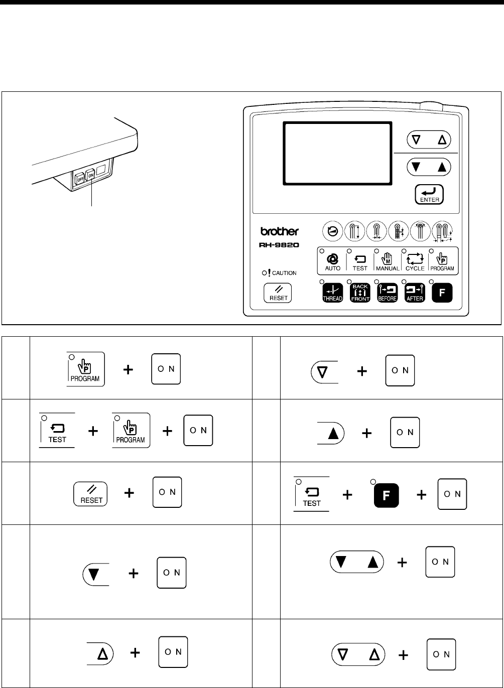
2. FUNCTION SETTINGS
2
RH-9820
2. FUNCTION SETTINGS
2-1. List of special functions when power is turned on
This section contains a list of functions and the key operations which are used to call the setting mode for the functions.
Push the power switch at the ON side
to turn on the power.
1 Memory switch setting mode (Standard)
Refer to the Instruction manual.
6 Output checking function
Refer to “2-7. Output checking method”.
2 Memory switch setting mode (Advanced)
Refer to “2-3. Memory switch setting method (Advanced)”.
7 Software version display function
Refer to “2-8. Software version checking method”.
3 Data initialization function
Refer to the Instruction manual.
8 Data read/write mode
Refer to “3-3. Data read/write mode”.
4 Error log display function
Refer to “2-5. Error history checking method”.
9 Home position adjustment mode
Refer to “7-33. Adjusting the looper base home position”
“7-34. Adjusting the feed base X home position and Y
home position”.
5 Input checking function
Refer to “2-6. Input checking method”.
10 Upper shaft stop position adjustment mode
Refer to “7-36. Adjusting the upper shaft stop position”.
4421Q
5056Q
0676B - 0680B 0681B - 0685B
2. FUNCTION SETTINGS
3 RH-9820
2-2. List of advanced functions
This section contains a list of advanced functions and the key operations which are used to call the setting mode for the
functions.
1 Production counter setting mode
Refer to the Instruction manual.
2
Data read/write mode
Refer to “3-3. Data read/write mode”.
4550Q
0708B 0709B
2. FUNCTION SETTINGS
4
RH-9820
2-3. Memory switch setting method (Advanced)
The settings for the memory switches are valid for all programs.
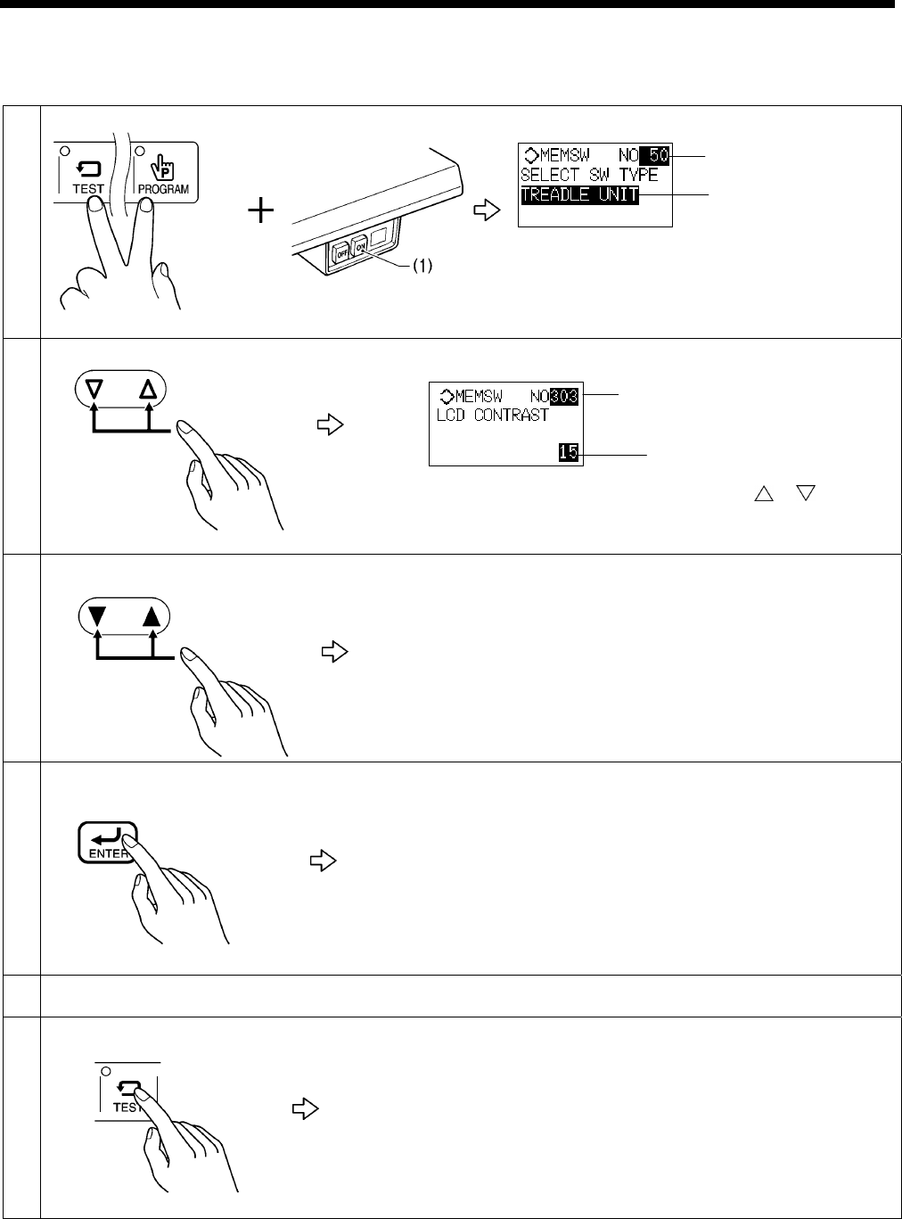
1 While pressing the TEST key and the PROGRAM key, push the POWER switch at the ON side (1).
* The mode will switch to memory switch mode.
* The memory switch number (A) will appear in the top part of
the display, and the setting (B) for that number will appear in
the bottom part of the display.
2 Select the number (A) for the memory switch that you would like to change the setting for.
* If you press and hold the F key while pressing the or key at this
time, only the memory switches whose current setting values are
different from the default values will appear.
3 Change the memory switch setting (B).
* If you would like to return the setting which is currently being displayed
to the default value, press the RESET key.
* If the memory switch setting is different from the original setting, the
display will flash.
4 Apply the changed setting.
The setting for the memory switch will be stored and (B) will stop flashing
and illuminate steadily.
NOTE:
The changed settings will be enabled after memory switch mode has been
exited.
5 Repeat steps 2 to 4 above to change other memory switch settings.
6 [To exit memory switch mode]
Normal sewing machine operation will then be possible.
(A)
(A)
0413B
0322B
0323B
0414B
0415B
0448B
(B)
0598B
(B)
2. FUNCTION SETTINGS
5 RH-9820
2-4. List of memory switch settings
Memory switches which have a “*” in the default value column (050, 752, 850, 851, 852 and 853) are ignored when memory
switch initialization is carried out.
The settings for these memory switches are only changed when the ENTER key is pressed in memory switch mode.
For operator
No. Setting
range Setting items Default
value
Switching between 1-pedal and 2-pedal operation
* Displayed when using a hand start switch or 2-pedal foot switch
1 When the start switch is pressed, the work clamp is lowered and the sewing machine
starts.
001
2 When the start switch is pressed, the work clamp is lowered.
After that, the sewing machine starts operating when the start switch is pressed.
2
F key assignment
OFF The Help screen is displayed while the F key is being pressed.
300
1 - 40 Operates as a 7th shortcut key.
* The numerals indicate the parameter numbers.
OFF
Parameter checking column (1) in automatic mode
1 Shows the sewing length.
301
2 Shows the sewing pitch.
1
Parameter checking column (2) in automatic mode
3 Shows the sewing speed.
302
4 Shows the number of stitches.
3
Display screen contrast
303 0 - 30 The higher the value, the greater the contrast. 15
Number of eyelet buttonholes when the fly indexer is used
* This is displayed when the fly indexer is enabled.
500
2 - 9 The number of eyelet buttonholes can be set.
* If the number of buttonholes is 5 or more, a cloth feed bar (sold separately) is required.
2
Fly setting position when the fly indexer is used
* This is displayed when the fly indexer is enabled.
1 The material (fly) setting position is always at the left edge.
After sewing is finished, the cloth feed bar returns to the left edge.
501
2 The material (fly) setting position repeatedly alternates between the left and right edges.
2
(2)
0222B
0222B
(1)

2. FUNCTION SETTINGS
6
RH-9820
Work clamp settings
No. Setting
range Setting items Default
value
Sewing machine starting procedure
* This is not overwritten by CF card data.
Hand start switch or 2-pedal foot switch
050
Treadle
*
Delay time for 1-pedal operation when cutting before sewing is set (ms)
* This is displayed when 1-pedal operation is being used.
051
0 - 800
When carrying out automatic sewing with cutting before sewing, the hammer operates
only after the set delay time has passed.
Setting can be carried out in units of 50 ms.
0
Work clamp operating position for treadle
* This is displayed when treadle operation is being used.
052
105 - 125 When a smaller value is set, the amount that the treadle is depressed to reach the work
clamp operating position becomes smaller.
115
Sewing machine starting position for treadle
* This is displayed when treadle operation is being used.
053
135 - 175 When a smaller value is set, the amount that the treadle is depressed to reach the
sewing machine starting position becomes smaller.
155
Work clamp raising operation position for treadle
* This is displayed when treadle operation is being used.
054
65 - 85 When a larger value is set, the amount that the treadle is depressed backward to reach
the work clamp raising operating position becomes smaller.
75
Work clamp operation standby for treadle
* This is displayed when treadle operation is being used.
OFF After the work clamp has been lowered, the work clamp is raised when the treadle is
moved to the neutral position.
055
ON
After the work clamp has been lowered, the work clamp is held in the lowered position
even when the treadle is moved to the neutral position, and the work clamp is raised
when the treadle is depressed backward.
OFF
Work clamp down operation when feed base is forward
OFF When the feed base moves to the forward setting position after sewing is finished, the
work clamp moves while it is still raised.
056
ON
When the feed base moves to the forward setting position after sewing is finished, the
work clamp moves while being lowered at the same time, and once the work clamp
finishes moving, it is raised.
OFF
Work clamp raising allowed during test feeding
OFF Raising of the work clamp is not allowed during test feeding.
057
ON
The work clamp can be raised during test feeding when the following operations are
carried out.
(A) For hand start switch or 2-pedal foot switch operation: Press the work clamp switch.
(B) For treadle operation: Depress the treadle backward.
When test feeding is carried out again, the following operations must be carried out to
lower the work clamp.
(A) For hand start switch or 2-pedal foot switch operation: Press the work clamp switch.
(B) For treadle operation: Depress the treadle.
OFF
Work clamp operation after automatic sewing is finished
OFF After automatic sewing is finished, work clamp is raised.
058
ON
After automatic sewing is finished, work clamp remains lowered.
To raise the work clamp, carry out the following operations.
(A) For hand start switch or 2-pedal foot switch operation: Press the work clamp switch.
(B) For treadle operation: Depress the treadle backward.
* When using the fly indexer, this function is disabled.
OFF

2. FUNCTION SETTINGS
7 RH-9820
Upper shaft control settings
No. Setting
range Setting items Default
value
Needle up stop when operation is paused
OFF Upper shaft stops immediately when sewing is paused.
150
ON Upper shaft stops at needle up stop position when sewing is paused.
ON
Upper shaft speed correction (rpm)
151 -30 - 30 Correction can be carried out with respect to the setting speed.
Setting can be carried out in units of 10 rpm.
0
Upper shaft final stitch speed (rpm)
152 700 - 900 The speed for the final stitch can be set.
Setting can be carried out in units of 10 rpm.
800
Upper shaft speed immediately before stopping (rpm)
153 250 - 450 The speed immediately before stopping can be set.
Setting can be carried out in units of 10 rpm.
350
Current limit value during upper shaft acceleration
154 1 - 8 When a larger value is set, a larger amount of current flows during acceleration. 8
Current limit value during upper shaft deceleration
155 1 - 8 When a larger value is set, a larger amount of current flows during deceleration. 1
Upper shaft stopping distance (°)
156 2.5 - 17.5 When a larger value is set, the interval for stopping control becomes longer.
Setting can be carried out in units of 0.5°.
11
Brake release speed when upper shaft stops
157 1 - 5 When a larger value is set, the brake is released more quickly. 3
NOTE:
Do not change the settings for Nos. 151 - 157 unless specifically instructed to by the manufacturer.

2. FUNCTION SETTINGS
8
RH-9820
Feed control settings
No. Setting
range Setting items Default
value
Feed timing correction (°)
250 -20 - 20 When a smaller value is set, the feed timing is advanced.
Setting can be carried out in units of 2°.
0
Automatic upper shaft deceleration to emphasize feeding
OFF Normal
251
ON
The proportional feed time for each stitch is reduced from normal in order to prevent
needle deflection.
* This may be limited by the sewing speed.
OFF
Y axis test feeding speed correction when feed base changes to forward setting (Hz)
252 -3500 - 0
When a smaller value is set, the test feeding speed in the Y axis direction becomes
slower.
Setting can be carried out in units of 100 Hz.
-2500
X axis test feeding speed correction (Hz)
253 -300 - 0
When a smaller value is set, the test feeding speed in the X axis direction becomes
slower.
Setting can be carried out in units of 50 Hz.
0
Y axis test feeding speed correction (Hz)
254 -2500 - 0*1
When a smaller value is set, the test feeding speed in the Y axis direction becomes
slower.
Setting can be carried out in units of 50 Hz.
0
θ axis test feeding speed correction (Hz)
255 -500 - 0
When a smaller value is set, the test feeding speed in the θ axis direction becomes
slower.
Setting can be carried out in units of 50 Hz.
0
Number of home position start cycles
OFF After sewing is finished, home position detection is not carried out.
256
1 - 9 Home position detection is carried out for the number of sewing cycles set.
OFF
X axis home position detection speed correction (ms)
257 0 - 2.0
When a larger value is set, the home position detection speed in the X axis direction
becomes slower.
Setting can be carried out in units of 0.1 ms.
0
Y axis home position detection speed correction (ms)
258 0 - 2.0
When a larger value is set, the home position detection speed in the Y axis direction
becomes slower.
Setting can be carried out in units of 0.1 ms.
0
θ axis home position detection speed correction (ms)
259 0 - 2.0
When a larger value is set, the home position detection speed in the θ axis direction
becomes slower.
Setting can be carried out in units of 0.1 ms.
0
*1… If the version of the main control program (MN) is 1.0.00, the range will be “-1000 to 0”.

2. FUNCTION SETTINGS
9 RH-9820
Panel operation settings
No. Setting
range Setting items Default
value
Disabling program mode
OFF Normal
350
ON Switching to program mode is disabled.
Shortcut keys are also disabled.
OFF
Disabling cycle program mode
OFF Normal
351
ON Switching to cycle program mode is disabled.
OFF
Disabling changing of production counter
OFF Normal
352
ON Changing the production counter is disabled.
OFF
Disabling changing of sewing speed
OFF Normal
353
ON Changing the sewing speed (parameter No. 01) is disabled.
OFF
Disabling changing of program number
OFF Normal
354
ON Changing the program number is disabled.
* However, the steps in cycle programs can be changed.
OFF
Disabling changing to cutting before sewing
OFF Normal
355
ON
Changing to cutting before sewing is disabled.
* If cutting before sewing is the current setting before this is changed, the setting will
change automatically to no cutting.
OFF
Disabling changing to cutting after sewing
OFF Normal
356
ON
Changing to cutting after sewing is disabled.
* If cutting after sewing is the current setting before this is changed, the setting will
change automatically to no cutting.
OFF
User program settings
No. Setting
range Setting items Default
value
Maximum sewing speed (rpm)
450 1000 - 2500 A limit to the maximum sewing speed can be set.
Setting can be carried out in units of 100 rpm.
2500
Maximum number of cycle programs
451 0 - 9 The number of effective cycle programs can be set.
* If cycle programs are never used, it can be useful to set this to 0.
9
Production counter when using cycle programs
OFF The counter is updated each time a buttonhole is sewn.
452
ON The counter is updated each time a single cycle is completed.
OFF
Maximum cutting space (mm)
453 0.5 - 0.8
This sets the maximum value for the cutting space.
* If setting this to 0.8 mm, adjust so that the needle plate and the throat plate do not
interfere with each other. (Refer to “7-20. Adjusting the positions of the work clamp
plates”.)
0.5
Maximum straight bartack length (mm)
454 6 - 9
This sets the maximum straight bartack length.
* If setting this to 9 mm, adjust so that the needle plate and the throat plate do not
interfere with each other. (Refer to “7-20. Adjusting the positions of the work clamp
plates”.)
6
Additional zigzag width when no cutting is set (mm)
455 0 - 1.0
When sewing using no cutting, the value set here is added automatically to the zigzag
width.
Setting can be carried out in units of 0.1 mm.
0

2. FUNCTION SETTINGS
10
RH-9820
Device settings
No. Setting
range Setting items Default
value
Hammer on time (ms)
550 25 - 200
When a larger value is set, the period of contact between the hammer and the knife
becomes longer.
Setting can be carried out in units of 5 ms.
Note: If this is set to a larger value than necessary, it will shorten the useful life of
the hammer and the knife.
25
Hammer home position recognition height
551 150 - 170
In the standby condition, an error (E650) will occur if the value which is read by the
hammer position sensor is less than this value.
* This setting is enabled when hammer home position error checking is enabled.
160
Hammer home position error checking
OFF Hammer home position error checking disabled
* This is used when there is a problem with the hammer position sensor.
552
ON Hammer home position error checking enabled
ON
Verification of hammer raised position using timer (ms)
OFF Verification of the hammer raised position is carried out based on the hammer position
sensor.
553
50 - 500
Verification of the hammer raised position is carried out based on the timer.
Setting can be carried out in units of 50 ms.
* This is used when there is a problem with the hammer position sensor.
OFF
Verification of hammer lowered position using timer (ms)
OFF Verification of the hammer lowered position is carried out based on the hammer position
sensor.
554
100 - 500
Verification of the hammer lowered position is carried out based on the timer.
Setting can be carried out in units of 100 ms.
* This is used when there is a problem with the hammer position sensor.
OFF
Upper thread remaining amount increase (mm)
OFF Normal
555
1 - 3
By delaying the upper thread trimming timing by the amount set, it is possible to increase
the amount of upper thread remaining from normal.
Setting can be carried out in units of 1 mm.
OFF
Upper thread tension release off timing (ms)
* This is only displayed for -00 and -01 specifications.
556
0 - 100
When a larger value is set, the upper thread release off timing is delayed after upper
thread trimming.
Setting can be carried out in units of 2 ms.
* This is only enabled for -00 and -01 specifications.
50
Upper thread tension release off timing (ms)
* This is only displayed for -02 specifications.
557
0 - 100
When a larger value is set, the upper thread release off timing is delayed after upper
thread trimming.
Setting can be carried out in units of 2 ms.
* This is only enabled for -02 specifications.
50
Disabling use of lower thread trimmer
* This is only displayed for -01 and -02 specifications.
OFF Normal (lower thread trimmer operates)
558
ON Operation of the lower thread trimmer is disabled.
* This is only enabled for -01 and -02 specifications.
OFF
Verification of lower thread trimming off using timer (ms)
* This is only displayed for -01 and -02 specifications.
OFF Verification that the lower thread trimmer is off is carried out based on the lower thread
trimming off sensor.
559
5 - 50
Verification that the lower thread trimmer is off is carried out based on the timer.
Setting can be carried out in units of 5 ms.
* This is used when there is a problem with the lower thread trimming off sensor.
* This is only enabled for -01 and -02 specifications.
OFF

2. FUNCTION SETTINGS
11 RH-9820
No. Setting
range Setting items Default
value
Lower thread trimming timing (ms)
* This is only displayed for -02 specifications.
560
0 - 100
When a larger value is set, the lower thread trimming timing is delayed by more.
Setting can be carried out in units of 5 ms.
* This is only enabled for -02 specifications.
0
Upper thread breakage detector (option)
* This is not overwritten by CF card data.
OFF Upper thread breakage detector is disabled.
561
ON Upper thread breakage detector is enabled.
OFF
Number of stitches before upper thread breakage is detected
* This is displayed when the upper thread breakage detector is enabled.
562
1 - 9 Upper thread breakage detection starts after the set number of stitches has been sewn.
5
Number of stitches for upper thread breakage judgment
563 2 - 7 An upper thread breakage error occurs when the upper thread breakage signal is
continuously on for the set number of stitches.
4
Upper thread nipper device (option)
* This is not overwritten by CF card data.
OFF Upper thread nipper device is disabled.
564
ON Upper thread nipper device is enabled.
OFF
Upper thread nipper device closing timing correction (mm)
* This is displayed when the upper thread nipper device is enabled.
565
-10 - 10 When a larger value is set, the upper thread nipping timing is delayed by more.
Setting can be carried out in units of 1 mm.
0
Lapel device (option)
* This is not overwritten by CF card data.
OFF Lapel device is disabled.
566
ON
Lapel device is enabled.
* When a straight buttonhole program is selected, the sub-hammer is lowered.
* The material setting position is automatically set to the forward position.
OFF
Program number loaded based on straight buttonhole sensor
* This is displayed when the lapel device is enabled.
OFF Normal
567
1 - 20 When there is no material underneath the straight buttonhole sensor, the program
number which has been set is loaded, and the sub-hammer is lowered.
OFF
Program number for sub-hammer to be always lowered
* This is displayed when the lapel device is enabled.
OFF Normal
568
1 - 20
When the program number that has been set is sewn, the sub-hammer is always
lowered.
* This is not affected by the status of the straight buttonhole sensor or the program
settings (eyelet pattern).
OFF
Error checking for straight buttonhole sensor
* This is displayed when the lapel device is enabled.
OFF Error checking disabled
569
ON
Error checking enabled
An error (E942) occurs in the following cases.
(A) When there is material underneath the sensor and an attempt is made to sew a
straight buttonhole program
(B) When there is no material underneath the sensor and an attempt is made to sew an
eyelet buttonhole program
OFF

2. FUNCTION SETTINGS
12
RH-9820
No. Setting
range Setting items Default
value
Sub-hammer on time (ms)
* This is displayed when the lapel device is enabled.
570
5 - 100
When a larger value is set, the period of contact between the sub-hammer and the knife
becomes longer.
Setting can be carried out in units of 5 ms.
Note: If this is set to a larger value than necessary, it will shorten the useful life of
the sub-hammer and the knife.
5
No cutting operation using straight buttonhole sensor
OFF Normal
571
ON When sewing when there is no material underneath the straight buttonhole sensor, no
cutting is carried out, regardless of the cutting operation setting on the panel.
OFF
Fly indexer (option)
* This is not overwritten by CF card data.
OFF Fly indexer is disabled.
572
ON Fly indexer is enabled.
OFF
* If No. 567 and No. 568 have both been set, only the setting for No. 567 will be enabled.
* If No. 567 and No. 569 have both been set, only the setting for No. 567 will be enabled.
* If No. 568 and No. 569 have both been set, both settings will be enabled.
* If No. 567 and No. 568 and No. 569 have all been set, only the setting for No. 567 will be enabled.
Error processing settings
No. Setting
range Setting items Default
value
Time before buzzer stops sounding (seconds)
OFF When an error occurs, the buzzer keeps sounding until the error is cleared.
650
5 - 15 When an error occurs, the buzzer sounds for the set time and then stops.
It can be set in units of 5 sconds.
OFF
Pulse motor energization status when a non-resettable error occurs
OFF When a non-resettable error occurs, pulse motor energization is turned off.
651
ON When a non-resettable error occurs, pulse motor energization remains on.
OFF
Checking errors caused by box fan stopping
* The box fan is not currently installed.
OFF No checking of errors caused by box fan stopping.
652
ON Checking of errors caused by box fan stopping.
OFF
Assembly and maintenance settings
No. Setting
range Setting items Default
value
Continuous sewing permission
OFF Normal
750
ON Continuous sewing is allowed.
Continuous sewing can be carried out by keeping the start switch pressed.
OFF
Continuous sewing interval (ms)
* This is displayed when continuous sewing is allowed.
751
0 - 2500 The continuous sewing interval can be set.
Setting can be carried out in units of 100 ms.
1000
X cutting position correction value (mm)
* This is not overwritten by CF card data.
752
-0.50 - 0.50 The setting value is added as the X cutting position correction value for all programs.
Setting can be carried out in units of 0.05 mm.
*

2. FUNCTION SETTINGS
13 RH-9820
Specifications and destination settings
No. Setting
range Setting items Default
value
Machine head specifications
* This is not overwritten by CF card data.
NOTE: Always be sure to set this to match the machine head specifications.
-00 Sets to -00 specifications.
-01 Sets to -01 specifications.
850
-02 Sets to -02 specifications.
*
Work clamp size
* This is only displayed for -02 specifications.
* This is not overwritten by CF card data.
NOTE: Always be sure to set this to match the work clamp specifications.
L1422 Sets to L1422 specifications.
The setting range for the sewing length will be 14 - 22 mm.
L1826 Sets to L1826 specifications.
The setting range for the sewing length will be 18 - 26 mm.
L2230 Sets to L2230 specifications.
The setting range for the sewing length will be 22 - 30 mm.
L2634 Sets to L2634 specifications.
The setting range for the sewing length will be 26 - 34 mm.
851
L3442 Sets to L3442 specifications.
The setting range for the sewing length will be 34 - 42 mm.
*
Circular stitch work clamp
* This is only displayed for -00 and -01 specifications.
* This is not overwritten by CF card data.
NOTE: Always be sure to set this to match the work clamp specifications.
OFF When using a normal (not circular stitch) work clamp
852
ON When using a circular stitch work clamp
Parameters only for circular stitches will be displayed when programming.
*
Language
* This is not overwritten by CF card data.
853
English
Japanese
Chinese
Spanish
German
French
Italian
Turkish
Portuguese
Indonesian
Vietnamese (Ver. 1.1.00 or later)
Russian (Ver. 1.1.00 or later)
The language can be selected from 12 available languages.
*
Sewing fold point correction value (mm)
OFF Normal
854
6
Straight buttonholes can be formed with the eyelet knife still installed.
At this time, the sewing fold point will be 6 mm forward of the normal point.
In addition, the maximum sewing length for straight buttonholes will be 6 mm smaller
than normal.
* This is enabled when sewing straight buttonholes.
OFF
2. FUNCTION SETTINGS
14
RH-9820
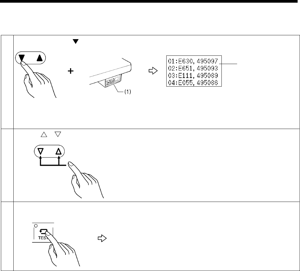
2-5. Error history checking method
The past error history can be checked by the following procedure.
1 While holding down the key, push the POWER switch at the ON side (1).
The error history (A) will be displayed. (The display starting from the left
side will be: history number, error code and production counter.)
2 When the or key is pressed, the history numbers will change.
* Up to 64 history events can be recorded, starting from the latest to be
recorded. (No. 1 will be the latest error that has occurred.)
3 [To exit error history checking mode]
The sewing machine will change to home position detection standby.
(A)
0413B
0718B
0448B
0979B
2. FUNCTION SETTINGS
15 RH-9820
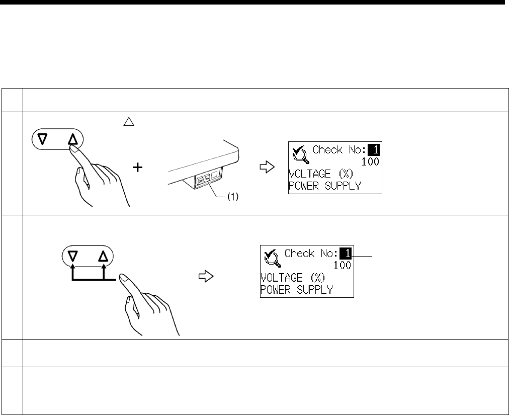
2-6. Input checking method
Use this to check for any malfunctions of the operation panel keys, circuit boards or sensors, and for checking for broken cords
and for adjusting sensor positions. This checks if the CPU is reading signals from the key and the sensor correctly.
1 Release the air.
2 While holding down the key, push the POWER switch at the ON side (1).
The mode will switch to input checking mode.
3 Select the check number (A) to be checked.
4 Refer to the input check list for key and sensor responses.
5 [To return to normal operation]
Press the POWER switch at the OFF side to turn off the power, turn on the air, and then turn the power back on.
0732B
0732B
(A)
0413B
0980B

2. FUNCTION SETTINGS
16
RH-9820
<Input check list>
No. Check item Checking method Judgment
1 Power supply voltage → Normally around 100%
2 X axis home position sensor Move the feed base to the left and
right by hand.
Left area: No switching ON/OFF
Right area: Switches ON/OFF
3 X axis encoder signal Move the feed base to the left and
right by hand.
Left direction: Up
Right direction: Down
* When the power is turned on, the
position will be 0.
4 Y axis home position sensor Move the feed base forward and
back by hand.
Forward area: OFF
Backward area: ON
5 Y axis encoder signal Move the feed base forward and
back by hand.
Forward direction: Up
Backward direction: Down
* When the power is turned on, the
position will be 0.
6 θ axis home position sensor Turn the looper base by hand.
Counterclockwise turning area: No
switching ON/OFF
Clockwise turning area: Switches ON/OFF
7 θ axis encoder signal Turn the looper base by hand.
Counterclockwise direction: Up
Clockwise direction: Down
* When the power is turned on, the
position will be 0.
8 Treadle analog value Operate the treadle.
When depressed backward: About 48
When at neutral position: About 100
When depressed forward: About 190
9 Work clamp switch Press the work clamp switch. ON: When pressed
OFF: When not pressed
10 Start switch Press the start switch. ON: When pressed
OFF: When not pressed
11 STOP switch connection
signal → ON: Connected
OFF: Not connected
12 STOP switch Press the STOP switch. ON: When pressed
OFF: When not pressed
13 Machine head safety switch Tilt back the machine head. ON: Normal condition
OFF: Machine head is tilted back
14 Hammer position sensor → Normally around 190
15 Lower thread trimming OFF
sensor
Turn the lower thread trimming
cylinder on and off manually.
ON: When cylinder is off
OFF: When cylinder is on
16 Fan lock detection signal → ON: Fan is not operating
OFF: Fan is operating
17 Zigzag sensor Turn the upper shaft pulley by
hand.
ON: Inner zigzag
OFF: Outer zigzag
18 Needle up signal Turn the upper shaft pulley by
hand.
ON: Raised
OFF: Not raised
19 Needle drop signal Turn the upper shaft pulley by
hand.
ON: Lowered
OFF: Not lowered
20 Upper shaft encoder signal Turn the upper shaft pulley by
hand.
Normal rotation: Up
Reverse rotation: Down
* Normally within the range of 0 - 179.
However, an unstable value may be
displayed just before a single rotation
is completed.

2. FUNCTION SETTINGS
17 RH-9820
No. Check item Checking method Judgment
21 key
22 key
23 ENTER key
24 Shortcut 1 key
25 Shortcut 2 key
26 Shortcut 3 key
27 Shortcut 4 key
28 Shortcut 5 key
29 Shortcut 6 key
30 AUTO key
31 TEST key
32 MANUAL key
33 CYCLE key
34 PROGRAM key
35 RESET key
36 THREAD key
37 FRONT/BACK key
38 BEFORE key
39 AFTER key
40 F key
Press the corresponding key. ON: When pressed
OFF: When not pressed
41 Upper thread breakage
detection signal
Move the upper thread back and
forth inside the sensor.
ON: No moving back and forth
OFF: Moving back and forth
42 Straight buttonhole position
sensor
Move the sub-hammer up and
down by hand.
ON: When sub-hammer is lowered
OFF: When sub-hammer is raised
43 Eyelet buttonhole position
sensor
Move the sub-hammer up and
down by hand.
ON: When sub-hammer is raised
OFF: When sub-hammer is lowered
44 Straight buttonhole sensor Place material underneath the
straight buttonhole sensor.
ON: No material underneath sensor
OFF: Material underneath sensor
45 Feed plate home position
sensor Install the feed plate. ON: Installed
OFF: Not installed
46 Feed plate drive cylinder left
sensor
Turn the feed plate drive cylinder
on and off manually.
ON: When cylinder is off
OFF: When cylinder is on
47 Feed plate drive cylinder
right sensor
Turn the feed plate drive cylinder
on and off manually.
ON: When cylinder is on
OFF: When cylinder is off
48 External input signal 1 → ON: Connected
OFF: Not connected
49 External input signal 2 → ON: Connected
OFF: Not connected
50 Sensor input 1
51 Sensor input 2
This is a spare signal for special orders.
(Applicable for main control program (MN) version 1.2.00 and later)
2. FUNCTION SETTINGS
18
RH-9820
2-7. Output checking method
Use this to check for any malfunctions of the circuit boards, and for checking for problems with drive mechanisms and broken
cords. This checks if the CPU output signal is working correctly.
NOTE:
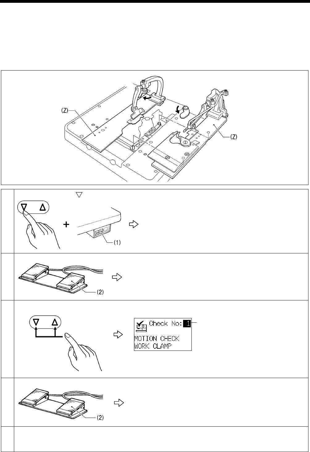
When checking operation, the mechanisms may be obstructed and become damaged, so remove the left and right work clamp
plates (Z) before checking output.
1 While holding down the key, push the POWER switch at the ON side (1).
The sewing machine will switch to starting standby mode.
2 Press the start switch (2).
The feed base will move to the home position.
3 Select the check number (A) to be checked.
* Refer to the output check list for the details of signals being checked.
4 Press the start switch (2).
The operation corresponding to the signal being checked will be carried
out.
5 [To return to normal operation]
Press the POWER switch at the OFF side to turn off the power, and then turn the power back on.
0749B
0413B 0731B
(A)
0981B
0982B
0982B

2. FUNCTION SETTINGS
19 RH-9820
<Output check list>
No. Check item Operation
1 Work clamp The work clamp will be lowered while the start switch is being pressed.
2 Spreader The spreader will open while the start switch is being pressed.
3 Upper thread
take-up The thread take-up lever will be lowered while the start switch is being pressed.
4 Lower tension
release
The lower tension will be released for 0.1 seconds.
* An error will not occur if the machine head is tilted back.
5 Gimp clamp
The gimp thread will be pressed for 0.1 seconds.
* -02 specifications only
6 X-axis motor
The buzzer will sound for 0.7 second, and then the work clamp will be lowered, the
spreader will open and the feed base will move +20 mm in the Y axis direction. The feed
base will then oscillate in the X axis direction within a range of -6 mm to +6 mm.
It will stop when the start switch is released.
7 Y-axis motor
The buzzer will sound for 0.7 second, and then the work clamp will be lowered and the
spreader will open. The feed base will then oscillate in the Y axis direction within a range
of 0 mm to +65 mm.
It will stop when the start switch is released.
8 θ-axis motor
The buzzer will sound for 0.7 second, and then the work clamp will be lowered and the
spreader will open. The looper base will then oscillate in the θ axis direction within a range
of -49.5° to +364.5°.
It will stop when the start switch is released.
9 Upper shaft motor
The buzzer will sound for 0.7 second, and then the work clamp will be lowered and the
upper shaft motor will start.
It will stop when the start switch is released.
The upper shaft encoder value (stop position) will be displayed immediately after the
upper shaft stops.
Normally a value of about 166 should be displayed.
The speed (1000 - 2500 rpm) can be changed using the and keys while the upper
shaft is stopped.
NOTE:
Remove the thread before carrying out this check in order to prevent needle
breakages.
10 Hammer
The buzzer will sound for 0.7 second, and then the work clamp will be lowered and the
hammer will be lowered.
NOTE:
This operation is dangerous, so check to make sure that there are no hands or
other objects underneath the hammer before carrying out the check.
11 Upper thread
trimming
The buzzer will sound for 0.7 second, and then the θshaft will turn 180° and upper thread
trimming will turn on.
12 Lower thread
trimming
-01 specifications:
The buzzer will sound for 0.7 second, and then the work clamp will be lowered and the
spreader will open, and then theθshaft will turn 135° and lower thread trimming will
turn on.
-02 specifications:
The buzzer will sound for 0.7 second, and then the spreader will open, and then the
θshaft will turn 180°and lower thread trimming will turn on.
13 Buzzer The buzzer will sound while the start switch is being pressed.

2. FUNCTION SETTINGS
20
RH-9820
No. Check item Operation
14 Panel indicators The 11 panel indicators will illuminate one by one.
15 Upper tension
release The upper tension will be released while the start switch is being pressed.
16 X axis encoder
The buzzer will sound for 0.7 second, and then the work clamp will be lowered, the
spreader will open and the feed will move +20 mm in the Y axis direction. The feed will
then oscillate in the X axis direction within a range of -6 mm to +6 mm.
It will stop when the start switch is released.
* Encoder offset is measured and displayed during operation.
17 Y axis encoder
The buzzer will sound for 0.7 second, and then the work clamp will be lowered and the
spreader will open. The feed will then oscillate in the Y axis direction within a range of 0
mm to +65 mm.
It will stop when the start switch is released.
* Encoder offset is measured and displayed during operation.
18 θ axis encoder
The buzzer will sound for 0.7 second, and then the work clamp will be lowered and the
spreader will open. The looper base will then oscillate in the θ axis direction within a range
of -49.5° to +364.5°.
It will stop when the start switch is released.
* Encoder offset is measured and displayed during operation.
19
Upper thread
nipper device
vertical movement
The upper thread nipper device will be lowered while the start switch is being pressed.
* Only with the upper thread nipper device
20
Upper thread
nipper device
forward/back
movement
The upper thread nipper device will move forward while the start switch is being pressed.
* Only with the upper thread nipper device
21
Upper thread
nipper device
opening/closing
The upper thread nipper device will open while the start switch is being pressed.
* Only with the upper thread nipper device
22 Sub-hammer
After the feed base has moved forward, the sub-hammer will be lowered.
* Only with the lapel device
23
Indexer feed plate
auxiliary clamp
arm
The feed plate auxiliary clamp arm of the fly indexer will turn on while the start switch is
being pressed.
* Only with the fly indexer
24 Indexer chuck
The chuck of the fly indexer will turn on while the start switch is being pressed.
* Only with the fly indexer
25 Indexer feed plate
The feed plate of the fly indexer will move to the right while the start switch is being
pressed.
* Only with the fly indexer
26 Valve output 1
27 Valve output 2
28 Valve output 3
29 Valve output 4
This is a spare signal for special orders.
(Applicable for main control program (MN) version 1.2.00 and later)
2. FUNCTION SETTINGS
21 RH-9820
2-8. Software version checking method
1 While holding down the key, push the POWER switch at the ON side(1).
The control program versions (A) will be displayed.
MN … Main control program
MT … Motor control program
PL … Panel control program
When the F key is pressed, the IPL versions (B) will be displayed.
MN … Main IPL
PL … Panel IPL
2 [To exit version checking mode]
The sewing machine will change to home position detection standby.
(A)
0721B
0710B
0452B
0448B
(B)
0983B

3. READING/WRITING DATA
22
RH-9820
3. READING/WRITING DATA
3-1. Precautions when handling CF cards (commercially available)
・ Use CF cards with a capacity of 32, 64, 128 or 256 MB.
・ Do not attempt to disassemble or modify the CF cards.
・ Do not forcibly bend, drop or scratch CF cards or place heavy objects on top of them.
・ Do not allow CF cards to come into contact with liquids such as water, oil, solvents or drinks.
・ Use and store the CF cards in places that are free from strong magnetic fields and electronic interference.
・ Do not use or store the CF cards in places which are subject to vibration, shocks, direct sunlight, dust from items such as
thread scraps, high humidity, sudden changes in temperature, or strong magnetic fields from equipment such as speakers.
・ Do not subject the CF cards to vibration or shocks or remove them from the sewing machine while data reading or writing is
in progress.
・ The data on the CF cards may become lost or corrupted due to some malfunction or accident. It is recommended that you
make backups of important data.
・ Be sure to turn off the power for the sewing machine before inserting and removing CF cards.
・ CF cards are already formatted at the time of purchase, so do not reformat them.
・ The recommended CF cards are commercially-available ones from SanDisk or HAGIWARA SYS-COM. CF cards from
other manufacturers can be used, but different formatting methods may mean that reading from or writing to such cards
may not be possible.
For more information, refer to the documentation provided with the CF card.
* This product is compatible with CF cards that have been formatted using the FAT16 method. Cards that have been
formatted using the FAT32 method cannot be used.
* CFTM is a trademark of SanDisk Corporation.
* Company names and product names appearing in this manual are trademarks or registered trademarks of the
respective owners. However, no TM or other similar symbols appear in the main text of this manual.
3-2. Structure of a CF card folder
Data type Folder name Filenames
Error logs \BROTHER\ISM\ISMDC00\ISMLDT00\
E*******.LDT ← Error log
M*******.LDT ← Memory switches
* ****** is a name unique to the sewing
machine.
Memory switches \BROTHER\ISM\ISMDC00\ ISMMSW.SEW
Parameter data As above ISMUPG.SEW
Main control
program \BROTHER\ISM\ISMSYS\ ISM03MN.MOT
Panel control
program As above ISM03PL.MOT
3. READING/WRITING DATA
23 RH-9820
3-3. Data read/write mode
1 With the power turned off, insert the CF card into the CF slot.
NOTE:
・ Make sure the CF card is facing the correct way.
(The side with the notches should be facing toward the left,
and the side with the small holes should be facing toward
the CF slot when the card is inserted.)
・ Always be sure to keep the cover closed except when
inserting and removing the CF card. If this is not done,
dust may get inside and cause problems with operation.
2 While pressing the TEST key and the F key, push the POWER switch at the ON side(1).
The mode will switch to data read/write mode.
* You can switch to data read/write mode by pressing
the TEST key and the F key together, even when in
test mode.
3 Select the desired read/write code (A). (Refer to <Read/write code list> given below.)
4 [To exit data read/write mode]
<Read/write code list>
Code Setting items
R1 Parameter data is read from the CF card.
W2 Parameter data is written to the CF card.
R3 Memory switch settings are read from the CF card.
W4 Memory switch settings are written to the CF card.
R5 The main control program is read from the CF card and used to update the firmware version.
W6 The error log is written to the CF card.
R7 The panel control program is read from the CF card and used to update the firmware version.
Small holes
Notches
0750B
0413B
(A)
0727B
0725B
0448B
0984B

3. READING/WRITING DATA
24
RH-9820
3-4. Reading parameter data from the CF card
1. Select R1 in data read/write mode.
2. Press the ENTER key.
The parameter data for all programs on the CF card will be read.
Once reading is complete, a “COMPLETED” message and the power off symbol
will be displayed.
3. Push the POWER switch to the OFF side to turn off the power, and then turn the
power back on again.
3-5. Writing parameter data to the CF card
1. Select W2 in data read/write mode.
2. Press the ENTER key.
The parameter data for all programs in the sewing machine will be written to the
CF card.
Once writing is complete, the buzzer will sound.
3. Press the TEST key.
Data read/write mode will end.
3-6. Reading memory switch data from the CF card
1. Select R3 in data read/write mode.
2. Press the ENTER key.
The memory switch data will be read from the CF card (except for some memory
switch data).
* Memory switch data relating to specifications and devices (050, 561, 564,
566, 572, 752, 850, 851, 852 and 853) will not be read.
Once writing is complete, a “COMPLETED” message and the power off
symbol will be displayed.
3. Push the POWER switch to the OFF side to turn off the power, and then turn the
power back on again.
3-7. Writing memory switch data to CF cards
1. Select W4 in data read/write mode.
2. Press the ENTER key.
All memory switch data from the sewing machine will be written to the CF card.
Once writing is complete, the buzzer will sound.
3. Press the TEST key.
Data read/write mode will end.
0724B
0728B
0723B
0727B
3. READING/WRITING DATA
25 RH-9820
3-8. Writing error log data to the CF card
1. Select W6 in data read/write mode.
2. Press the ENTER key.
The error log in the sewing machine will be written to the CF card.
The memory switch settings will also be written at this time.
However, the file destination will be different from the one mentioned in “3-7.”
above.
Once writing is complete, the buzzer will sound.
3. Press the TEST key.
Data read/write mode will end.
3-9. Updating the main control program
1. Select R5 in data read/write mode.
2. Press the ENTER key.
A confirmation message will be displayed.
3. Press the ENTER key. (If you press the RESET key, the operation will be
canceled.)
Firmware updating will start. (It should take about one minute.)
Once writing is complete, an “UPDATED SUCCESSFULLY” message and the
power off symbol will be displayed.
4. Push the POWER switch to the OFF side to turn off the power, and then turn the
power back on again.
3-10. Updating the panel control program
1. Select R7 in data read/write mode.
2. Press the ENTER key.
A confirmation message will be displayed.
3. Press the ENTER key. (If you press the RESET key, the operation will be
canceled.)
Firmware updating will start. (It should take about three minutes.)
Once writing is complete, a “COMPLETED” message and the power off symbol
will be displayed.
4. Push the POWER switch to the OFF side to turn off the power, and then turn the
power back on again.
0729B
0725B
0726B
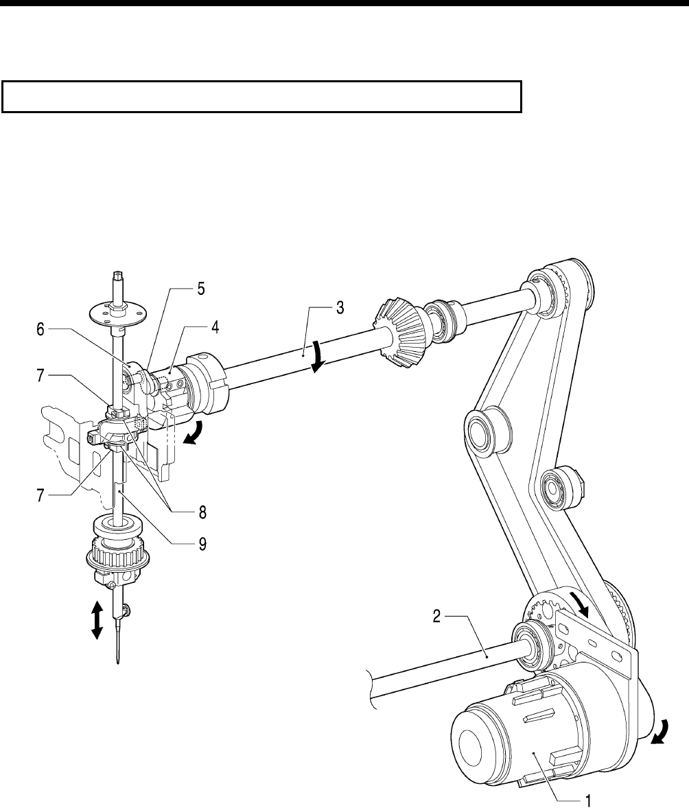
4. MECHANICAL DESCRIPTIONS
RH-9820 26
4. MECHANICAL DESCRIPTIONS
Each mechanism operates in the order of the numbers shown in the illustration.
* <number> indicate the flow of operations that occur separately from each other.
4-1. Upper shaft and Needle bar mechanisms
1. Motor assembly
2. Lower shaft
3. Upper shaft
4. Upper shaft crank
5. Needle bar crank
6. Crank rod unit
7. Needle bar clamp
8. Spacer
9. Needle bar
0658B
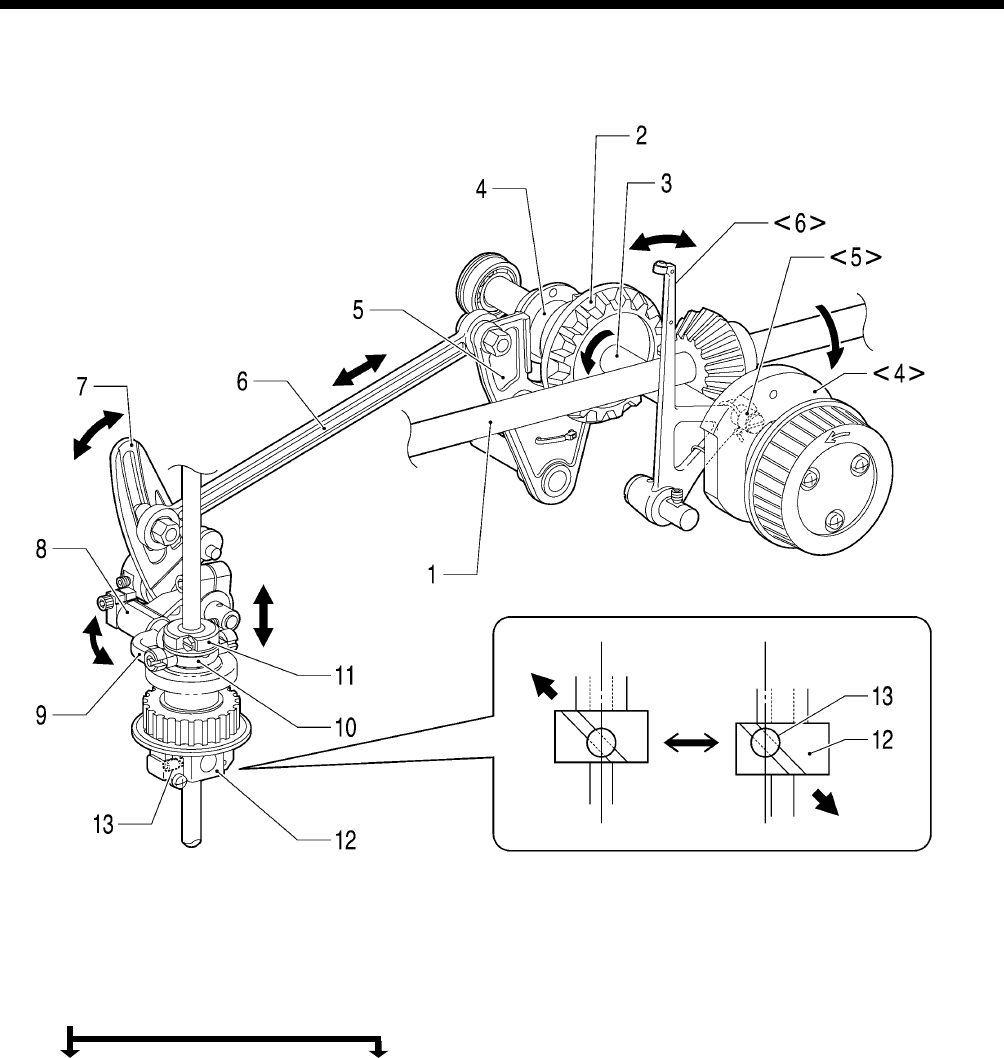
4. MECHANICAL DESCRIPTIONS
RH-9820
27
4-2. Zigzag and thread take-up mechanisms
1. Upper shaft
2. Hypoid gear
3. Orthogonal shaft
4. Zigzag cam <4> Roller take-up cam
5. Zigzag fork <5> Thread take-up roller
6. Zigzag connecting rod <6> Thread take-up
7. Zigzag crank
8. Zigzag driving lever
9. Zigzag lever
10. Zigzag horizon link
11. Needle bar block bracket
12. Needle bar block
13. Needle bar guide
0659B
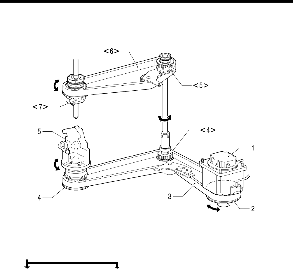
4. MECHANICAL DESCRIPTIONS
RH-9820 28
4-3. Needle bar rocking mechanism
1. Pulse motor R
2. Theta M pulley assembly
3. Timing belt D
4. Looper pulley assembly <4> Driving looper shaft assembly
5. Looper base assembly <5> Vertical shaft timing pulley U assembly
<6> Timing belt U
<7> Needle bar gear block unit
0660B
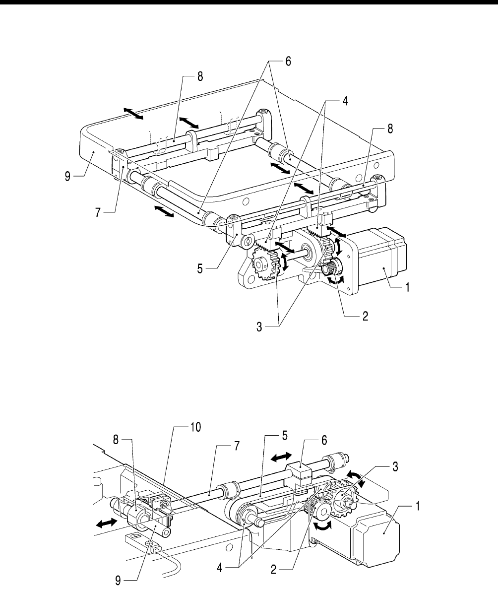
4. MECHANICAL DESCRIPTIONS
RH-9820
29
4-4. Feed mechanism
<X direction>
1. Pulse motor X
2. Feed gear
3. Idler gear
4. X rack
5. X feed shaft holder N
6. X feed guide shaft A, B
7. X feed shaft holder S
8. Y feed guide shaft
9. Feed base
<Y direction>
1. Pulse motor Y
2. Driving gear 20
3. Idler gear
4. Timing pulley
5. Y Timing belt
6. Y driving shaft holder, Belt holder
7. Y shaft
8. Y bearing
9. Y guide shaft
10. Feed base
0661B
0662B
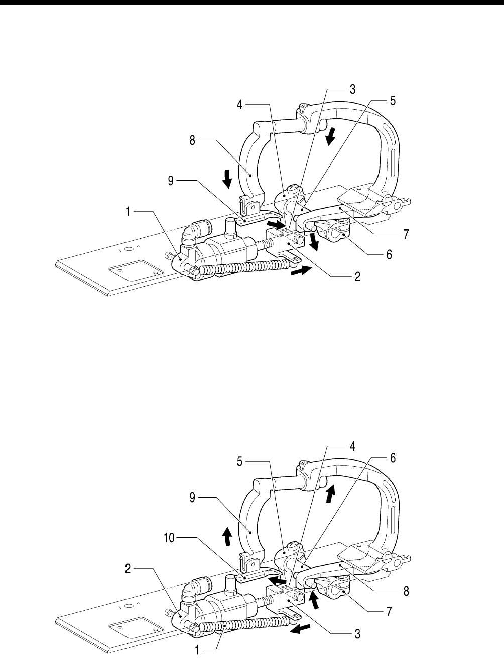
4. MECHANICAL DESCRIPTIONS
RH-9820 30
4-5. Presser foot mechanism
<When work clamp is lowered>
1. Clamp cylinder 16X10
2. Clamp cylinder rod
3. Clamp cylinder rod pin
4. Clamp driving lever
5. Clamp lever shaft
6. Clamp lever B
7. Clamp lever
8. Clamp arm
9. Work clamp
<When work clamp is raised>
Because the air is bled from the clamp cylinder, the force from the spring (1) has the opposite effect from when lowered.
1. Spring
2. Clamp cylinder 16X10
3. Clamp cylinder rod
4. Clamp cylinder rod pin
5. Clamp driving lever
6. Clamp lever shaft
7. Clamp lever B
8. Clamp lever
9. Clamp arm
10. Work clamp
0663B
0783B
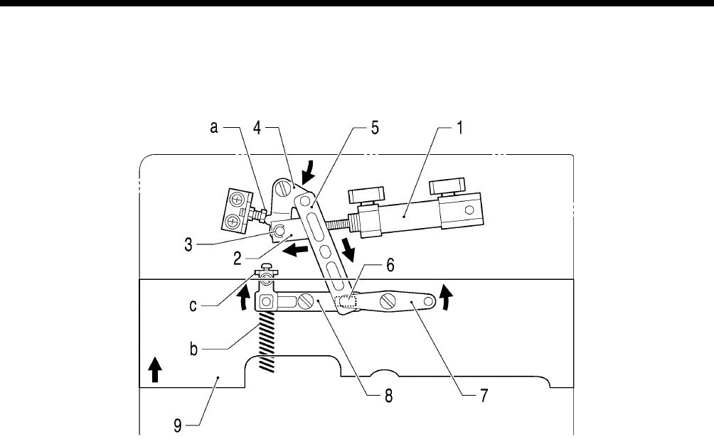
4. MECHANICAL DESCRIPTIONS
RH-9820
31
4-6. Cloth opening mechanism
<After operation>
1. Opening cylinder assembly 16X15
2. Opening cylinder rod
3. Opening cylinder rod pin
4. Opening driving lever
5. Opening connecting rod
6. Slide block
7. Fulcrum lever plate
8. Rocker lever
9. Work clamp plate
a. Bolt
b. Extension spring
c. Opening stopper plate
0664B
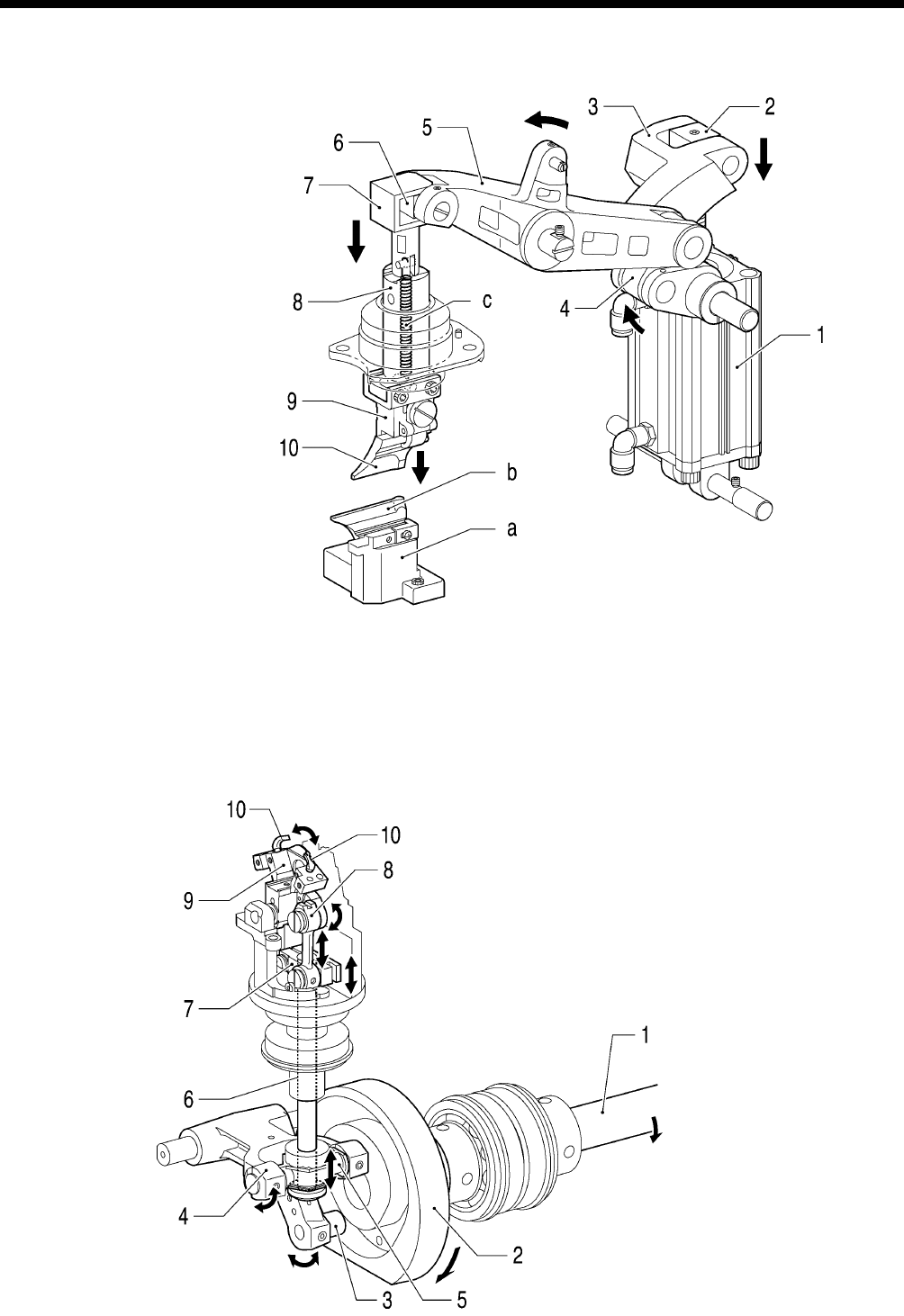
4. MECHANICAL DESCRIPTIONS
RH-9820 32
4-7. Cutter mechanism
1. Cylinder 63X100
2. Cylinder rod
3. Cutter lever
4. Cutter link
5. Cutter arm assembly
6. Cutter arm slide block
7. Driving shaft presser
8. Cutter driving shaft
9. Hammer bracket assembly
10. Hammer
a. Knife bracket unit
b. Knife
c. Spring extension
4-8. Looper mechanism
1. Lower shaft
2. Lower shaft cam
3. Lower shaft cam collar
4. Looper lever assembly
5. Looper driving plate
6. Looper driving shaft
7. Looper link clamp
8. Looper link unit
9. LS holder base assembly
10. Looper
0665B
0666B
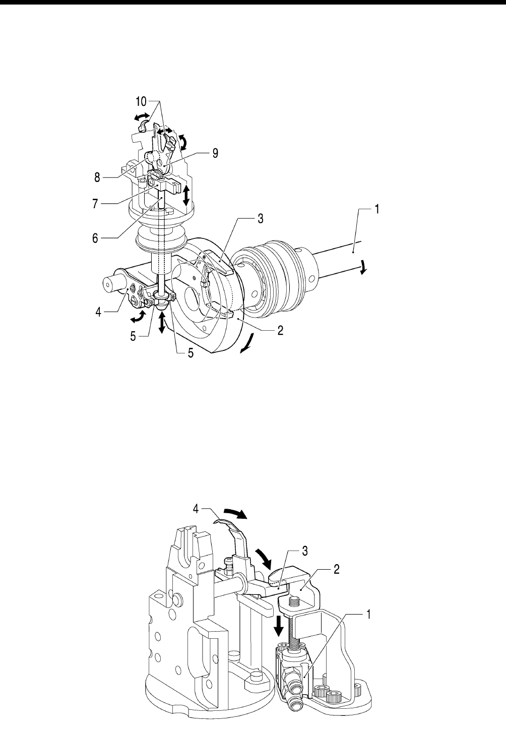
4. MECHANICAL DESCRIPTIONS
RH-9820
33
4-9. Spreader mechanism
1. Lower shaft
2. Lower shaft cam
3. Spreader lever A
4. Spreader lever B
5. Slide block
6. Spreader link shaft
7. Spreader link base
8. Spreader cam link
9. Spreader driving cam
10. Spreader
4-10. Upper thread trimmer mechanism
1. Upper thread trimmer cylinder
2. Hammer
3. Thread trimmer lever bracket
4. Upper movable knife
0667B
0668B
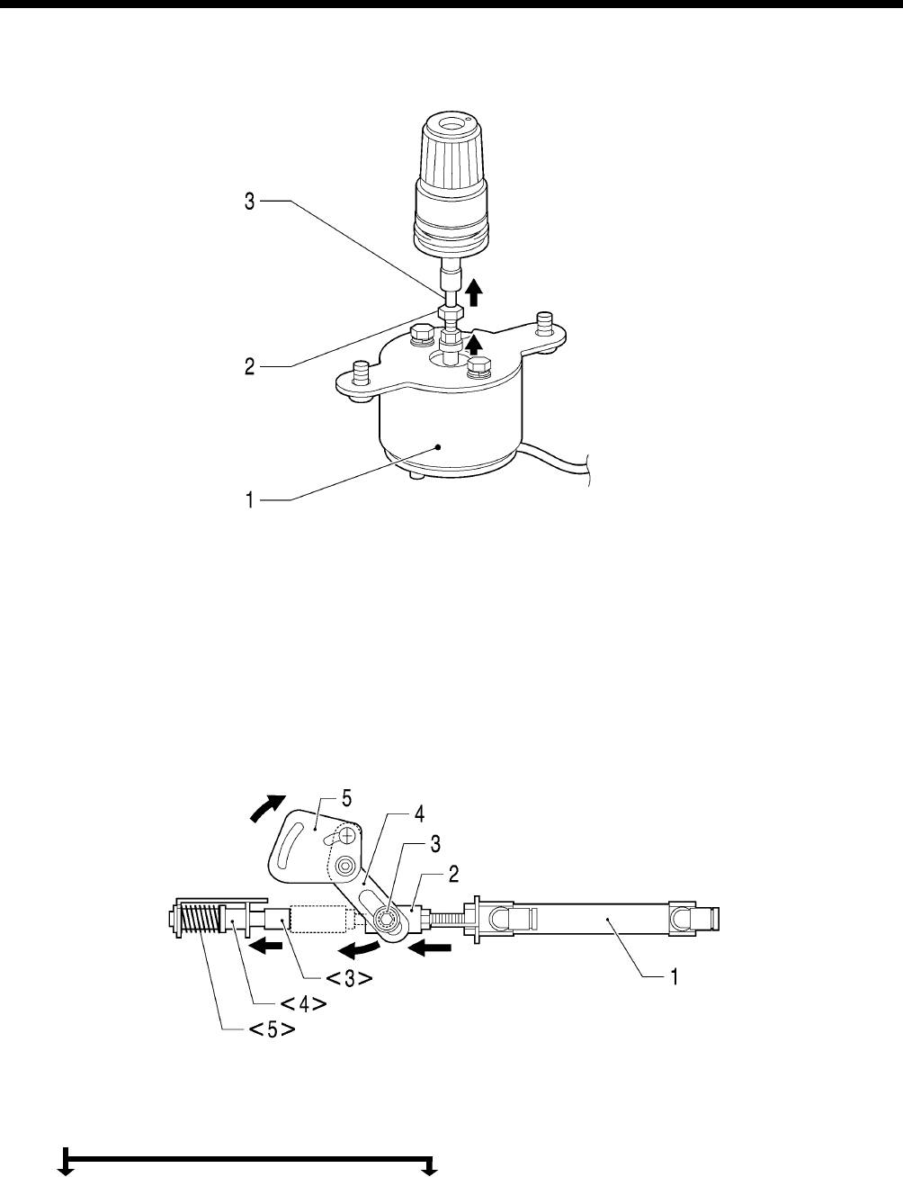
4. MECHANICAL DESCRIPTIONS
RH-9820 34
4-11. Upper tension release mechanism
1. Upper tension release solenoid
2. Bolt
3. Tension release pin
4-12. Upper thread take-up mechanism
1. Cylinder assembly 10-30
2. Cylinder joint A
3. Collar B <3> Rubber cushion
4. Thread take-up lever driving plate <4> Impact support shaft
5. Thread take-up lever plate <5> Spring compression A
0669B
0670B
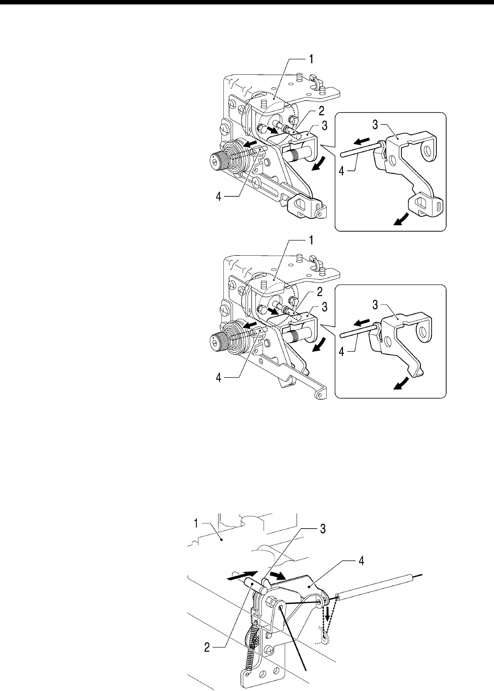
4. MECHANICAL DESCRIPTIONS
RH-9820
35
4-13. Lower thread release and lower thread take-up mechanisms
<-01>
1. Lower thread tension release solenoid
2. Lower solenoid shaft
3. Lower thread take-up guide lever
(thread take-up)
4. Tension release pin (tension release)
<-00, -02:Lower thread release only >
1. Lower tension release solenoid
2. Lower solenoid shaft
3. Lower thread release plate
4. Tension release pin (tension release)
4-14. Gimp thread take-up mechanism <-01 specifications only>
1. Feed bar (Y direction operation)
2. Gimp thread take-up guide collar
3. Gimp thread take-up G-E plate
4. Gimp thread take-up guide plate
0671B
0672B
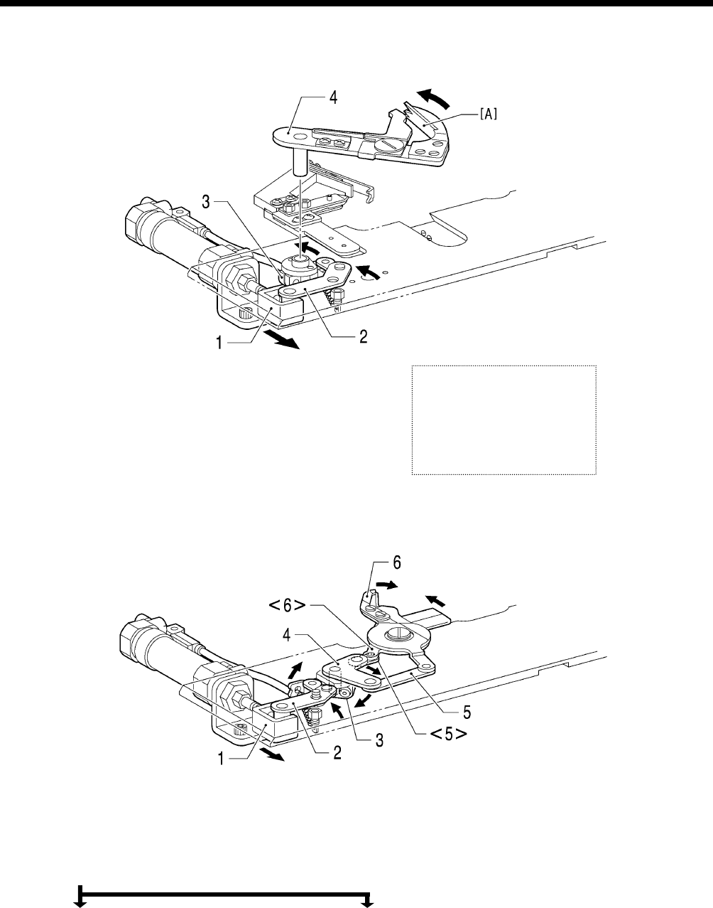
4. MECHANICAL DESCRIPTIONS
RH-9820 36
4-15. Lower thread trimmer mechanism
<-01>
1. Cylinder assembly 16X30 B
2. Thread trimmer lever
3. Thread cutter lever arm
4. Thread trimmer arm
<-02>
1. Cylinder 16X30 assembly B
2. Thread trimmer lever J assembly
3. Thread trimmer lever arm B
4. Movable knife driving plate
5. Thread trimmer link A assembly <5> Thread trimmer link B assembly
6. Movable knife L <6> Movable knife R
0673B
0674B
Refer to “Principle of the
thread handler” in “7-25-5.
A
djusting the thread handle
r
”
for details about the thread
handler [A].

4. MECHANICAL DESCRIPTIONS
RH-9820
37
5. DISASSEMBLY
RH-9820 38
5. DISASSEMBLY
DANGER
Wait at least 5 minutes after turning off the power switch and disconnecting the power cord from the
wall outlet before opening the cover of the control box. Touching areas where high voltages are present
can result in severe injury.
CAUTION
Disassembly should only be carried out by a
qualified technician.
Turn off the power switch and disconnect the
power cord at the following times. If this is not
done, the sewing machine may operate if the
start switch is pressed by mistake, which could
result in serious injury.
Disconnect the air hoses from the air supply
and wait for the needle on the pressure gauge
to drop to “0” before carrying out inspection,
adjustment and repair of any parts which use
the pneumatic equipment.
Be sure to wear protective goggles and gloves
when handling the lubricating oil and grease,
so that they do not get into your eyes or onto
your skin, otherwise inflammation can result.
Furthermore, do not drink the oil or eat the
grease under any circumstances, as they can
cause vomiting and diarrhea.
Keep the oil out of the reach of children.
Use only the proper replacement parts as
specified by Brother.
If any safety devices have been removed, be
absolutely sure to re-install them to their
original positions and check that they operate
correctly before using the machine.
Any problems in machine operation which
result from unauthorized modifications to the
machine will not be covered by the warranty.
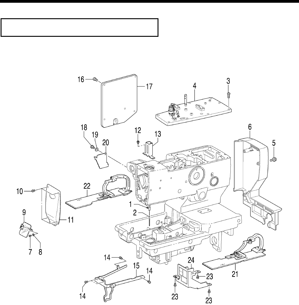
5. DISASSEMBLY
RH-9820
39
Disassemble the parts in the order shown in the illustration.
5-1. Covers and presser foot mechanism
* Start with the machine head in its upright position.
1. Screw (Loosen)
2. Needle
3. Screws [9 pcs]
4. Top cover
5. Screws with washers [4 pcs]
6. Belt cover
7. Screws [2 pcs]
8. Plain washers [2 pcs]
9. Eye guard
10. Screws [4 pcs]
11. Main plate
12. Socket bolts [2 pcs]
13. Needle bar guard
14. Screws [4 pcs]
15. Needle guide cover
16. Screws [5 pcs]
17. Rear cover
18. Shoulder screw
19. Wave washer
20. Zigzag window cover
21. Work clamp plate R assembly
22. Work clamp plate L assembly
(Tilt back the machine head.)
23. Screws [3 pcs]
24. Cam cover
1079B
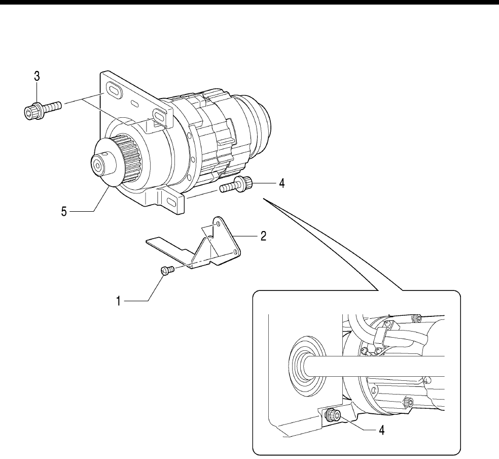
5. DISASSEMBLY
RH-9820 40
5-2. Upper shaft motor unit mechanism
* Start with the machine head in its upright position.
1. Screws [2 pcs]
2. Belt guide
3. Socket bolts with washers [2 pcs]
(Tilt back the machine head.)
4. Socket bolt with washer [1 pcs]
5. Upper shaft motor unit
1080B
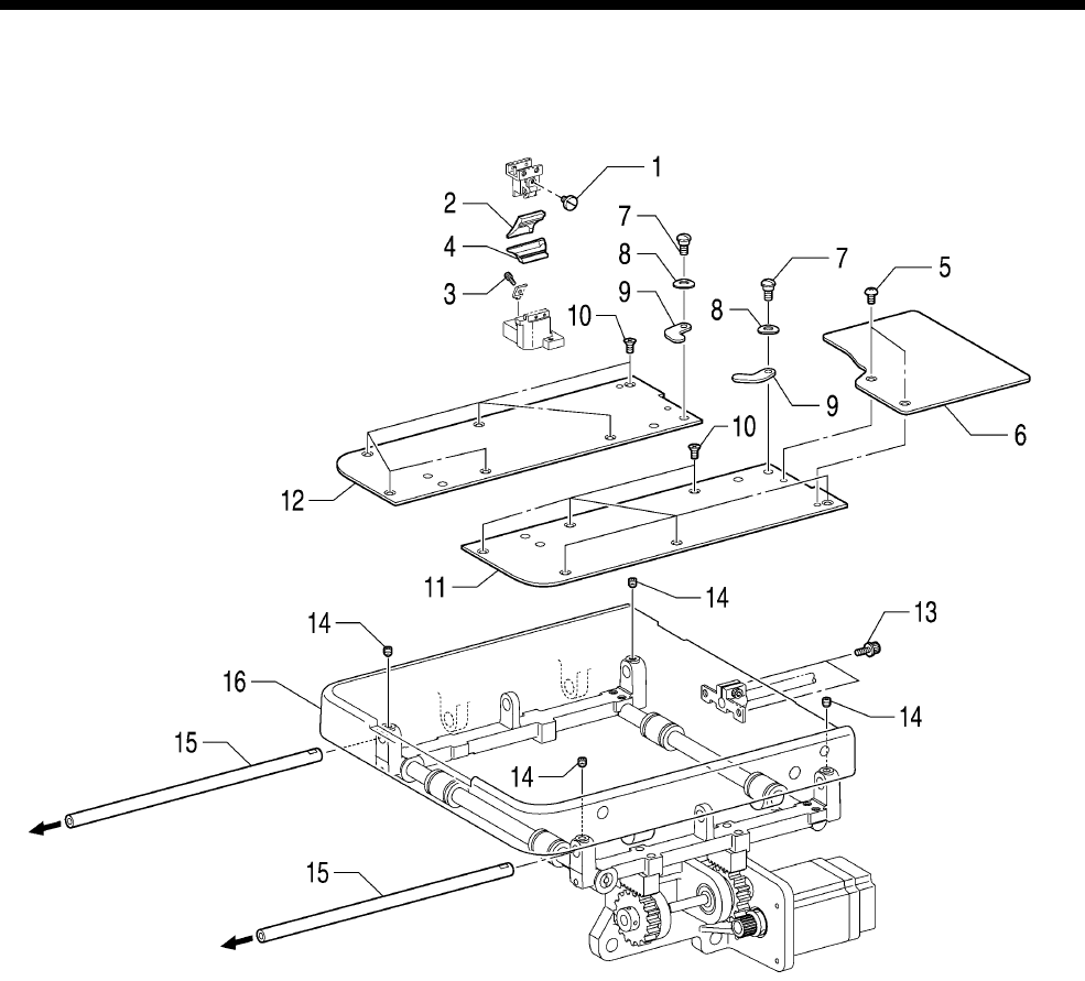
5. DISASSEMBLY
RH-9820
41
5-3. Feed mechanism
5-3-1. Feed base unit
* Carry out the following with the machine head in the upright position.
1. Screw (Loosen)
2. Hammer
3. Socket bolt (Loosen)
4. Knife
5. Truss screws [2 pcs]
6. Feed base cover U
7. Shoulder screws [2 pcs]
8. Bending washers [2 pcs]
9. Plate pressers [2 pcs]
10. Flat screws [12 pcs]
11. Feed base cover R
12. Feed base cover L
13. Socket bolts with washers
[2 pcs]
14. Set screws [4 pcs] (Loosen)
15. X feed guide shafts [2 pcs]
(Pull forward to remove)
16. Feed base unit
1081B
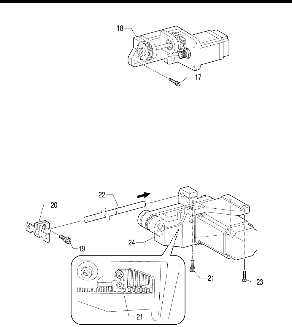
5. DISASSEMBLY
RH-9820 42
5-3-2. X feed unit
* Carry out the following with the machine head tilted back.
17. Socket bolts [3 pcs]
18. X feed assembly
5-3-3. Y feed unit
* Disassemble the “5-2. Upper shaft motor unit mechanism” before disassembling the “5-3-3. Y feed unit”.
* Start with the machine head in its upright position.
19. Socket bolt (Loosen)
20. Y shaft holder
(Tilt back the machine head.)
21. Socket bolt (Loosen)
(Return the machine head to its
upright position.)
22. Y shaft (Pull backward to remove)
(Tilt back the machine head.)
23. Socket bolts [3 pcs]
24. Y feed assembly
1082B
1083B
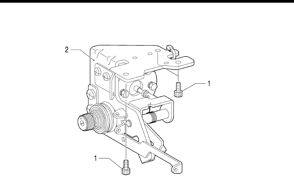
5. DISASSEMBLY
RH-9820
43
5-4. Lower thread tension mechanism
* Carry out the following with the machine head tilted back.
1. Socket bolts [3 pcs]
2. Lower thread guide adjust assembly
1084B
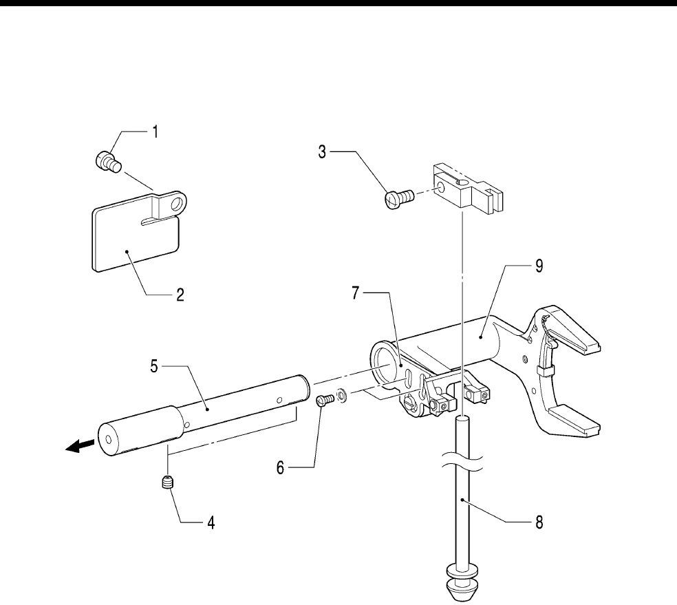
5. DISASSEMBLY
RH-9820 44
5-5. Spreader mechanism
* Carry out the disassembly procedure in “5-4. Lower thread tension mechanism” before the disassembly
procedure in “5-5. Spreader mechanism”.
* Carry out the following with the machine head tilted back.
1. Screw
2. Tube support B
3. Screw (Loosen)
4. Set screws [2 pcs] (Loosen)
5. Spreader lever shaft
6. Screws [2 pcs]
7. Spreader lever B assembly
8. Spreader lever shaft
9. Spreader lever A assembly
1085B
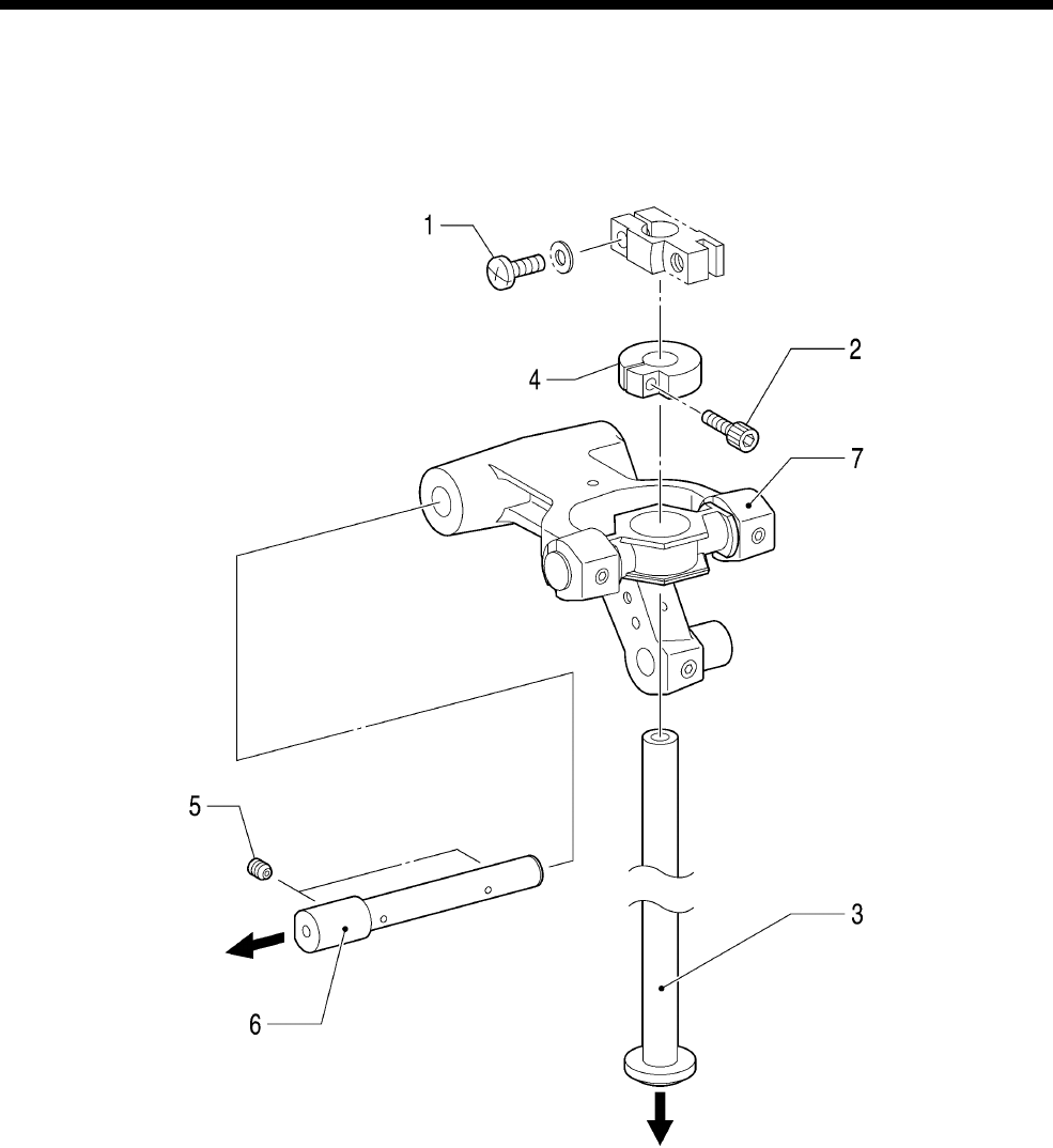
5. DISASSEMBLY
RH-9820
45
5-6. Looper mechanism
* Carry out the disassembly procedure in “5-5. Spreader mechanism” before the disassembly procedure in
“5-6. Looper mechanism”.
* Carry out the following with the machine head tilted back.
1. Screw (Loosen)
2. Socket bolt (Loosen)
3. Looper driving shaft
4. Looper driving shaft bracket
5. Set screws [2 pcs] (Loosen)
6. Looper lever shaft
7. Looper lever assembly
1086B
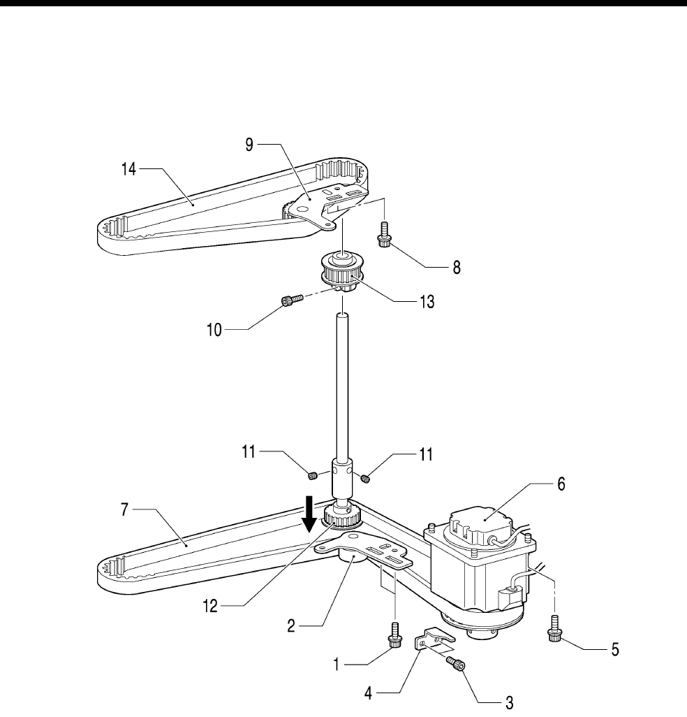
5. DISASSEMBLY
RH-9820 46
5-7. Needle bar rocking mechanism
* Carry out the disassembly procedure in “5-2. Upper shaft motor unit mechanism” before the disassembly
procedure in “5-7. Needle bar rocking mechanism”.
* Start with the machine head tilted back.
1. Socket bolts with washers
[2 pcs]
2. Tension pulley D assembly
3. Socket bolts [2 pcs]
4. Motor stopper
5. Socket bolts with washers
[4 pcs]
6. Pulse motor assembly R
7. Timing belt D
(Return the machine head to its
upright position.)
8. Socket bolts with washers
[2 pcs]
9. Tension pulley U assembly
10. Socket bolt (Loosen)
11. Set screws [2 pcs] (Loosen)
(Tilt back the machine head once
more.)
12. Driving looper shaft assembly
13. Vertical shaft timing pulley U
assembly
14. Timing belt U
1077B
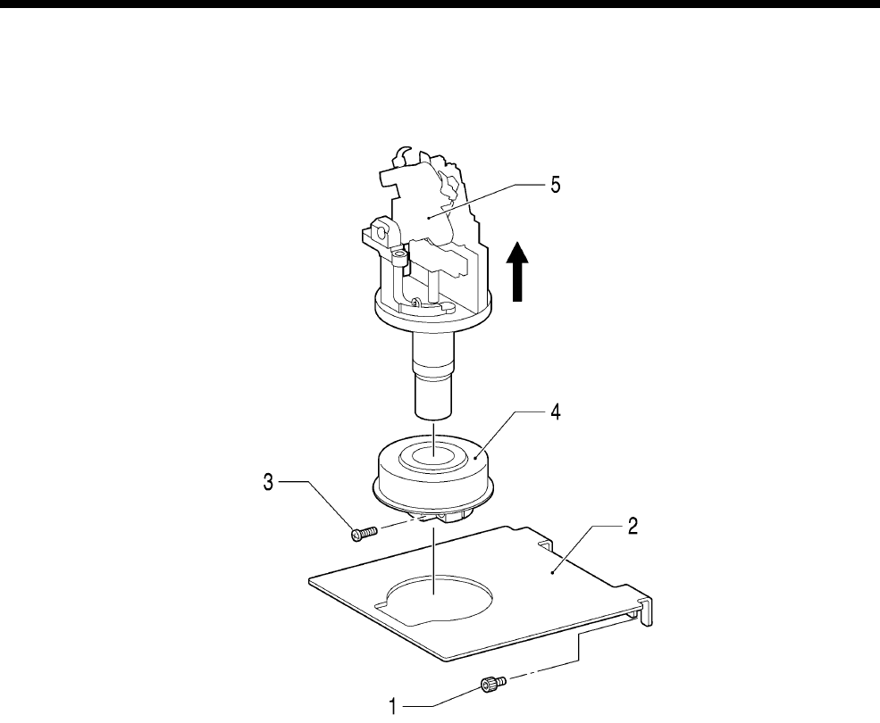
5. DISASSEMBLY
RH-9820
47
5-8. Looper base mechanism
* Carry out the disassembly procedure in “5-5. Spreader mechanism” and the “5-6. Looper mechanism”
before the disassembly procedure in “5-8. Looper base mechanism”.
* Carry out the following with the machine head tilted back.
1. Socket bolts [2 pcs]
2. Partition
3. Screw (Loosen)
4. Looper pulley (screw type)
5. Looper base unit
1078B
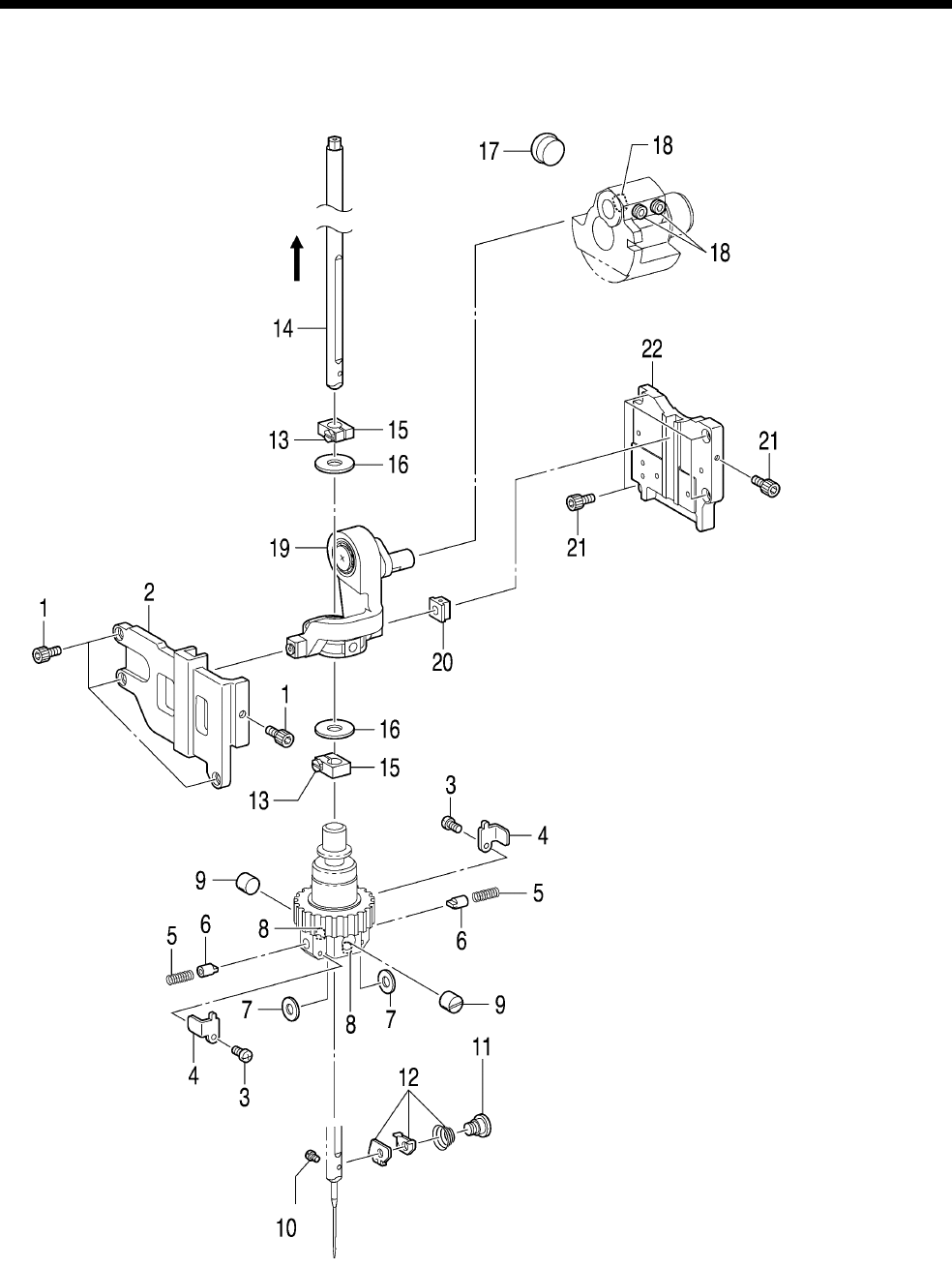
5. DISASSEMBLY
RH-9820 48
5-9. Needle bar mechanism
* Carry out the following with the
machine head in the upright
position.
1. Socket bolts [4 pcs]
2. Slide block guide F
3. Screws [2 pcs]
4. Needle bar guide support
plates [2 pcs]
5. Needle bar guide springs
[2 pcs]
6. Needle bar guides [2 pcs]
7. Plain washers [2 pcs]
8. Set screws [2 pcs] (Loosen)
9. Needle bar guide collars
[2 pcs]
10. Set screw
11. Shoulder screw
12. Tension spring, Needle thread
holder plate, Needle guide A
13. Screws [2 pcs] (Loosen)
14. Needle bar assembly
(Pull out from the top)
15. Needle bar clamp [2 pcs]
16. Washers [2 pcs]
17. Rubber cap
18. Set screws [3 pcs] (Loosen)
19. Needle bar crank, Crank rod
unit
20. Slide block
21. Socket bolts [5 pcs]
22. Slide block guide D
1088B
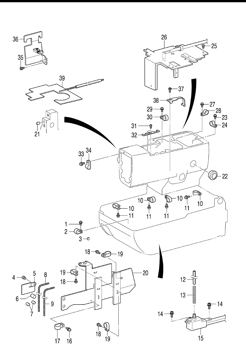
5. DISASSEMBLY
RH-9820
49
5-10. Lubrication
1089B

5. DISASSEMBLY
RH-9820 50
1. Screw
2. Cord holder
3. Felt
4. Screw
5. Tube support B
6. Felt
7. Felt
8. Wick
9. Wick
10. Cord holders (7N) [4 pcs]
11. Screws [4 pcs]
12. Oil tube
13. Tube clip spring
14. Socket bolts [2 pcs]
15. Sub-tank assembly
16. Screw
17. Cord holder (NK-3N)
18. Screws [3 pcs]
19. Cord holders #10 [3 pcs]
20. Lower shaft cover
assembly
21. Felt
22. Oil gauge window
23. Screw
24. Cord holder #5
25. Screws [4 pcs]
26. Oil plate assembly
27. Screw
28. Cord holder (NK-3N)
29. Screw
30. Cord holder (4N)
31. Screw
32. Cord holder
33. Screw
34. Cord holder (NK-3N)
35. Socket bolts [2 pcs]
36. Tube support assembly
(From this point on, disassemble
after the disassembly in “5-13.
Cutter mechanism” has been
done.)
37. Socket bolt
38. Tube guide
39. Felt assembly
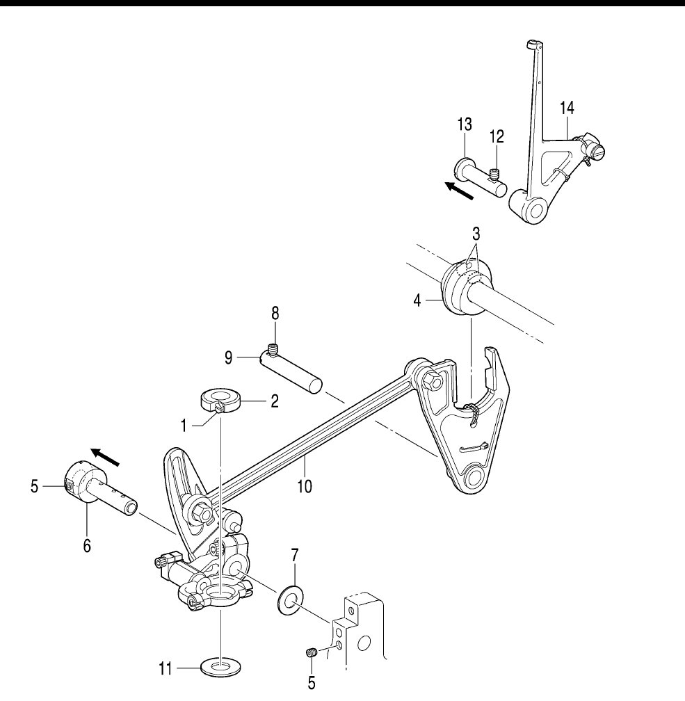
5. DISASSEMBLY
RH-9820
51
5-11. Zigzag and thread take-up mechanisms
* Carry out the following with the
machine head in the upright position.
<Zigzag mechanism>
1. Screw (Loosen)
2. Needle bar block bracket
(screw type)
3. Set screws [2 pcs] (Loosen)
4. Zigzag cam (Slide to remove
from zigzag fork.)
5. Set screws [2 pcs] (Loosen)
6. Zigzag coaxial rock shaft
(Pull out)
7. Spacer
8. Set screw (Loosen)
9. Zigzag fork support shaft
(Pull out)
10. Zigzag unit (Remove the whole
unit from the side of the arm
main plate.)
11. Needle bar block collar
<Thread take-up mechanism>
12. Set screw (Loosen)
13. Thread take-up L support shaft
(Pull out)
14. Thread take-up lever unit
(Remove the roller from the
grooved cam and lift upward.)
1090B
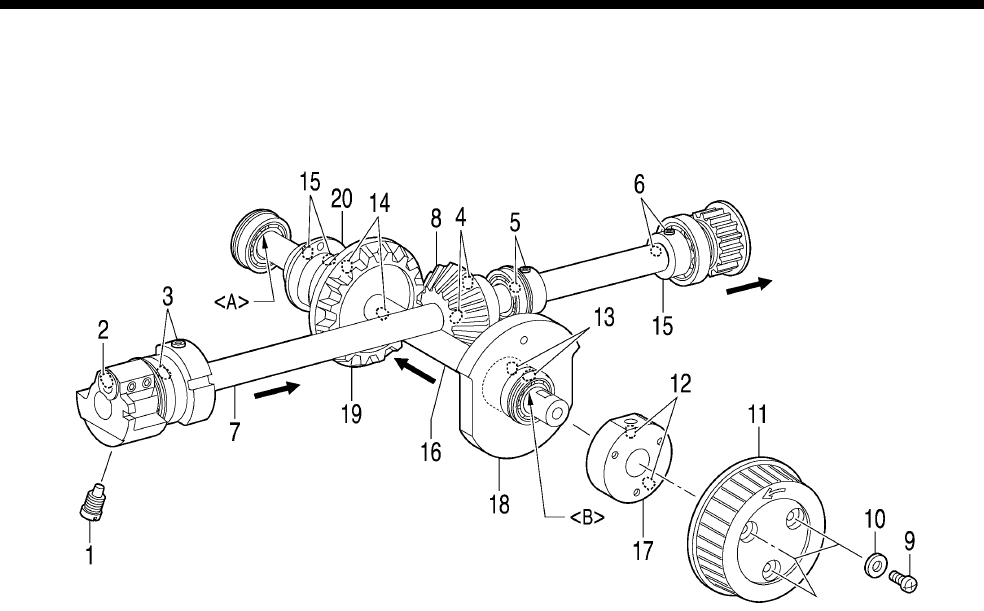
5. DISASSEMBLY
RH-9820 52
5-12. Upper shaft mechanism
* Carry out the following with the machine head in the upright position.
1. Screw
2. Set screw (Loosen)
3. Set screws [2 pcs]
(Loosen)
4. Set screws [2 pcs]
(Loosen)
5. Set screws [2 pcs]
(Loosen)
6. Set screws [2 pcs]
(Loosen)
7. Upper shaft unit
(Pull out from the back.)
8. Pinion
9. Screws [3 pcs]
10. Plain washers [3 pcs]
11. Pulley
12. Set screws [2 pcs] (Loosen)
13. Set screws [2 pcs] (Loosen)
14. Set screws [2 pcs] (Loosen)
15. Set screws [2 pcs] (Loosen)
16. Orthogonal shaft unit
(Pull out from the rear cover.)
17. Pulley base
18. Take-up cam roller
19. Gear
20. Zigzag cam
NOTE:
The bearing unit (16) and the bearing inner rings <A> and <B> are joined with adhesive, so avoid
disassembling them if possible.
1091B
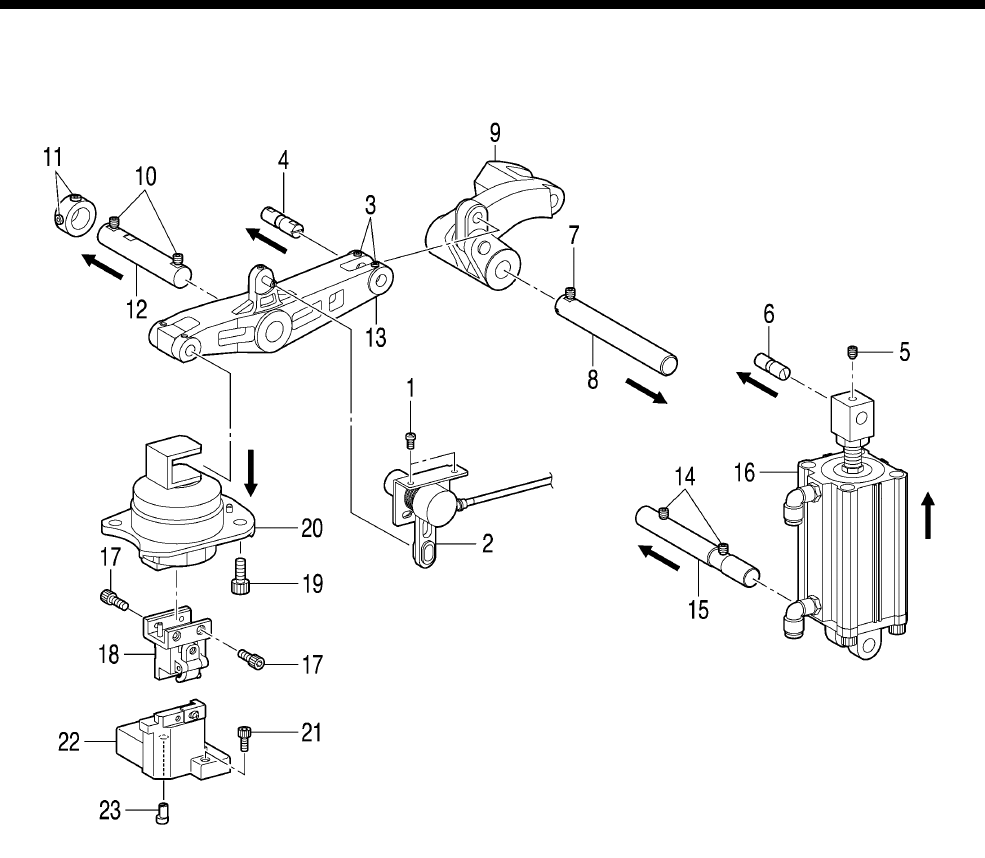
5. DISASSEMBLY
RH-9820
53
5-13. Cutter mechanism
* Start with the machine head in its upright position.
1. Screws [2 pcs]
2. Cutter sensor assembly
3. Set screws [2 pcs]
(Loosen)
4. Cutter arm pin (Pull out)
5. Set screw (Loosen)
6. Cylinder rod shaft
(Pull out)
7. Set screw (Loosen)
8. Cutter lever shaft
(Pull out)
9. Cutter lever assembly
10. Set screws [2 pcs]
(Loosen)
11. Set screws [2 pcs]
(Loosen)
12. Cutter arm shaft (Pull out)
13. Cutter arm assembly
(Tilt back the machine head.)
14. Set screws [2 pcs] (Loosen)
15. Cylinder support shaft (Pull out)
(Return the machine head to the
upright position once more.)
16. Cylinder assembly
(Lift up to remove)
17. Socket bolts [4 pcs]
18. Hammer bracket assembly
19. Socket bolts [3 pcs]
20. Cutter driving shaft unit
(Pull down to remove)
21. Socket bolt
22. Knife bracket unit
23. Eccentric pin
1092B
6. ASSEMBLY
RH-9820 54
6. ASSEMBLY
DANGER
Wait at least 5 minutes after turning off the power switch and disconnecting the power cord from the
wall outlet before opening the cover of the control box. Touching areas where high voltages are present
can result in severe injury.
CAUTION
Assembly should only be carried out by a
qualified technician.
Turn off the power switch and disconnect the
power cord at the following times. If this is not
done, the sewing machine may operate if the
start switch is pressed by mistake, which could
result in serious injury.
If the power switch needs to be left on when
carrying out some adjustment, be extremely
careful to observe all safety precautions.
Disconnect the air hoses from the air supply
and wait for the needle on the pressure gauge
to drop to “0” before carrying out inspection,
adjustment and repair of any parts which use
the pneumatic equipment.
Be sure to wear protective goggles and gloves
when handling the lubricating oil and grease,
so that they do not get into your eyes or onto
your skin, otherwise inflammation can result.
Furthermore, do not drink the oil or eat the
grease under any circumstances, as they can
cause vomiting and diarrhea.
Keep the oil out of the reach of children.
Use only the proper replacement parts as
specified by Brother.
If any safety devices have been removed, be
absolutely sure to re-install them to their
original positions and check that they operate
correctly before using the machine.
Any problems in machine operation which
result from unauthorized modifications to the
machine will not be covered by the warranty.
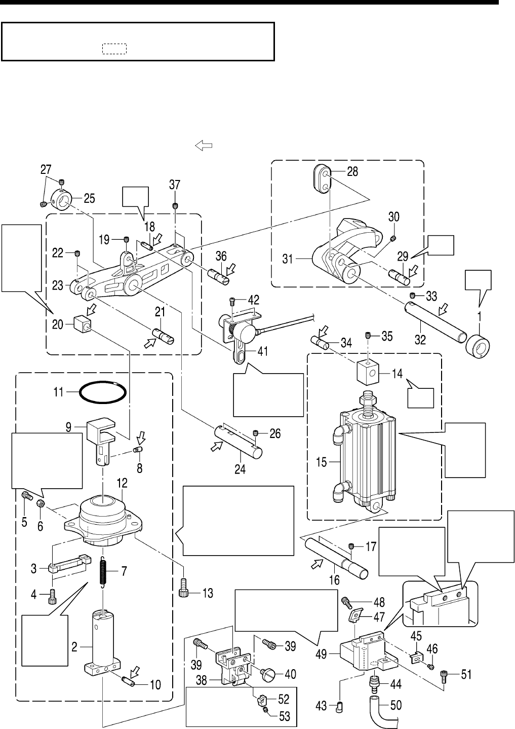
6. ASSEMBLY
RH-9820
55
・ Assemble each part in the order shown in the illustration.
・ Parts indicated by are part of the same assembly.
6-1. Cutter mechanism
* Carry out assembly steps <1> to <8> in “6-25. Lubrication and greasing and routing the oil tubes” before
carrying out the assembly in “6-1. Cutter mechanism”.
* Refer to the detailed descriptions on the next page for details on A to D in the illustration.
* Apply the grease specified by Brother (MOLYKOTE LONGTERM W2 manufactured by Dow Corning
Corporation) in the places indicated by .
0785B
Refer to “7-16-2.
Making fine adjustments
to the knife position”.
Refer to “7-14.
A
djusting the
axial play of
the hammer”.
A
djust so that the cutter
driving shaft (2) turns
smoothly with no play, and
then fully tighten the two
socket bolts (4).
Install so
that it is
not
twisted.
Insert so
that the
ground
surface
touches.
Place onto the
cutter sensor pin
(18).
Insert
from
top of
arm.
C
D
A
B
<For
-02-L1422,
L1826, L2230
specifications>
<For -00, -01,
-02-L2634,
L3442
specifications>
<Used with
-02-L1422, L1826,
L2230 s
p
ecifications>
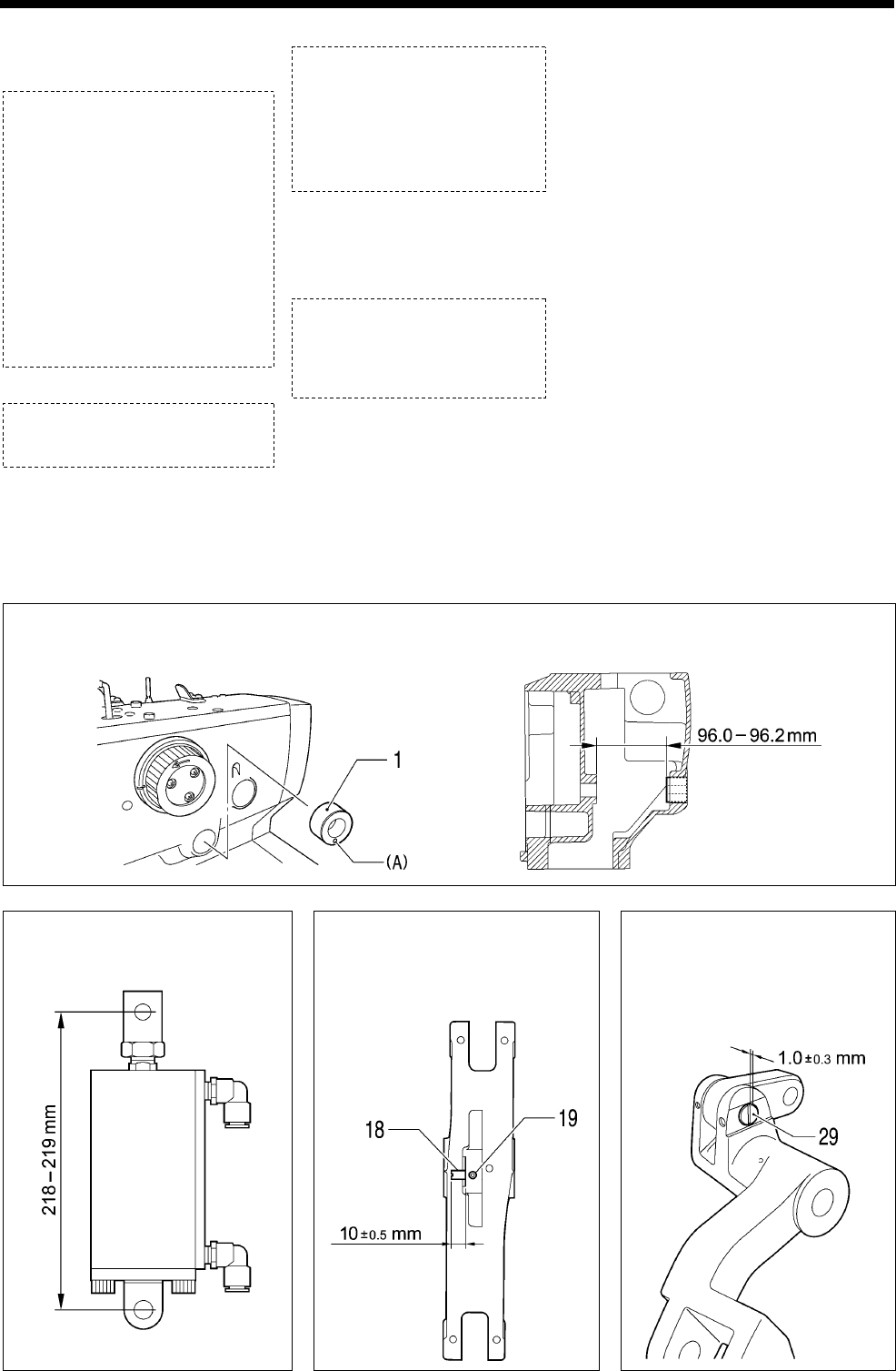
6. ASSEMBLY
RH-9820 56
1. Bush cutter lever shaft
2. Cutter driving shaft
3. Guide block
4. Socket bolts [2 pcs]
(Temporarily tighten)
5. Bolts [2 pcs]
6. Nuts [2 pcs]
7. Extension spring
8. Spring hook pin U
9. Driving shaft presser
10. Spring hook pin D
11. O Ring
12. Bush cutter shaft assembly
13. Socket bolts [3 pcs]
14. Cylinder rod
15. Cylinder
16. Cylinder support shaft
17. Set screw
18. Cutter sensor pin
19. Set screw
20. Cutter arm slide block
21. Cutter arm pin
22. Set screws [2 pcs]
23. Cutter arm
24. Cutter arm shaft
25. Set screw collar
26. Set screws [2 pcs]
27. Set screws [2 pcs]
28. Cutter link
29. Cutter arm pin
30. Set screws [2 pcs]
31. Cutter lever
32. Cutter lever shaft
33. Set screw
34. Cylinder rod shaft
35. Set screw
36. Cutter arm pin
37. Set screws [2 pcs]
38. Hammer bracket assembly
39. Socket bolts [4 pcs]
40. Knob screw
(Temporarily tighten)
41. Cutter sensor assembly
42. Screws [2 pcs]
43. Eccentric pin
44. Knife garbage joint
45. Block stopper plate
46. Screw (Temporarily tighten)
47. Knife block holder
48. Socket bolt
(Temporarily tighten)
49. Knife bracket
50. Knife trash tube
51. Socket bolts [3 pcs]
(Temporarily tighten)
<-02-L1422, L1826, L2230
specifications only>
52. Hammer spacer
53. Set screw
A Apply adhesive (Threebond 1373B) to the outer circumference of the bush cutter lever shaft (1), and
then press-fit it within the press-fitting dimensions shown in the illustration so that the hole (A) is facing
directly downward.
B Assemble as shown in the
illustration.
C Tighten the Set screw (19)
so that the cutter sensor pin
(18) protrudes by about 1.0
±0.5 mm.
D Insert the cutter arm pin
(29) so that the “-” side
protrudes from the end of
the lever by about 1.0±0.3
mm.
0786B
0787B 0788B
(When at maximum retraction)
0789B
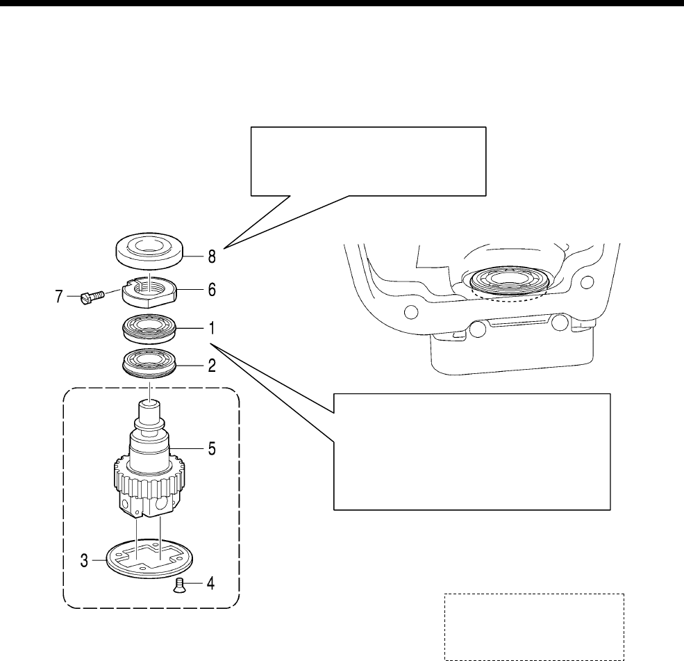
6. ASSEMBLY
RH-9820
57
6-2. Needle bar mechanism (1)
* Refer to “Adjusting the pressure of the needle bar gear block” on the next page.
1. Bearing
2. Bearing
3. Pulley flange
4. Screws [4 pcs]
5. Needle bar gear block
6. Needle bar gear nut
7. Screw
8. Gear nut cover
Push the needle bar gear block (5) in
as far as it will go. If it is not properl
y
inserted, oil leaks will occur.
A
pply sealant (Threebond 1212) to the oute
r
circumference of the bearing.
* Apply a small amount of sealant evenl
y
over the outer circumference. If the sealan
t
is not applied evenly over the whole
surface, oil leaks will occur.
0790B
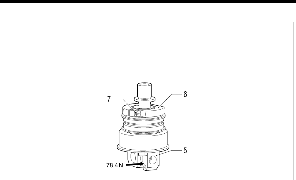
6. ASSEMBLY
RH-9820 58
Adjusting the pressure of the needle bar gear block
Secure the needle bar gear nut (6), and then while pushing the needle bar gear block (5) with a force of 78.4 N,
tighten the screw (7).
NOTE:
If pressure is not applied, it will not be possible to adjust the turning center for the needle bar and looper
base, and this will cause problems with sewing such as skipped stitches.
0791B
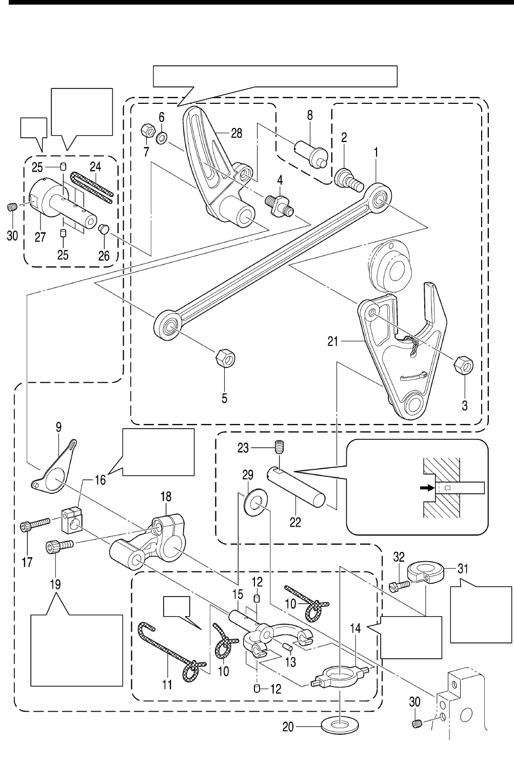
6. ASSEMBLY
RH-9820
59
6-3. Zigzag mechanism
* Refer to the detailed descriptions on the next page for details on A and B in the illustration.
A
djust so
that there
is no play.
Refer to “7-3.
A
djusting the
zigzag base line
position” when
fully tightening.
0849B
A
djust so that
there is no
play.
A
lign the end
of the shaft
with the edge
of the arm.
B
A
A
djust so
that there
is no play.
Refer to “7-2. Adjusting the zigzag width (stitch width).”
Check the
direction of
installation.
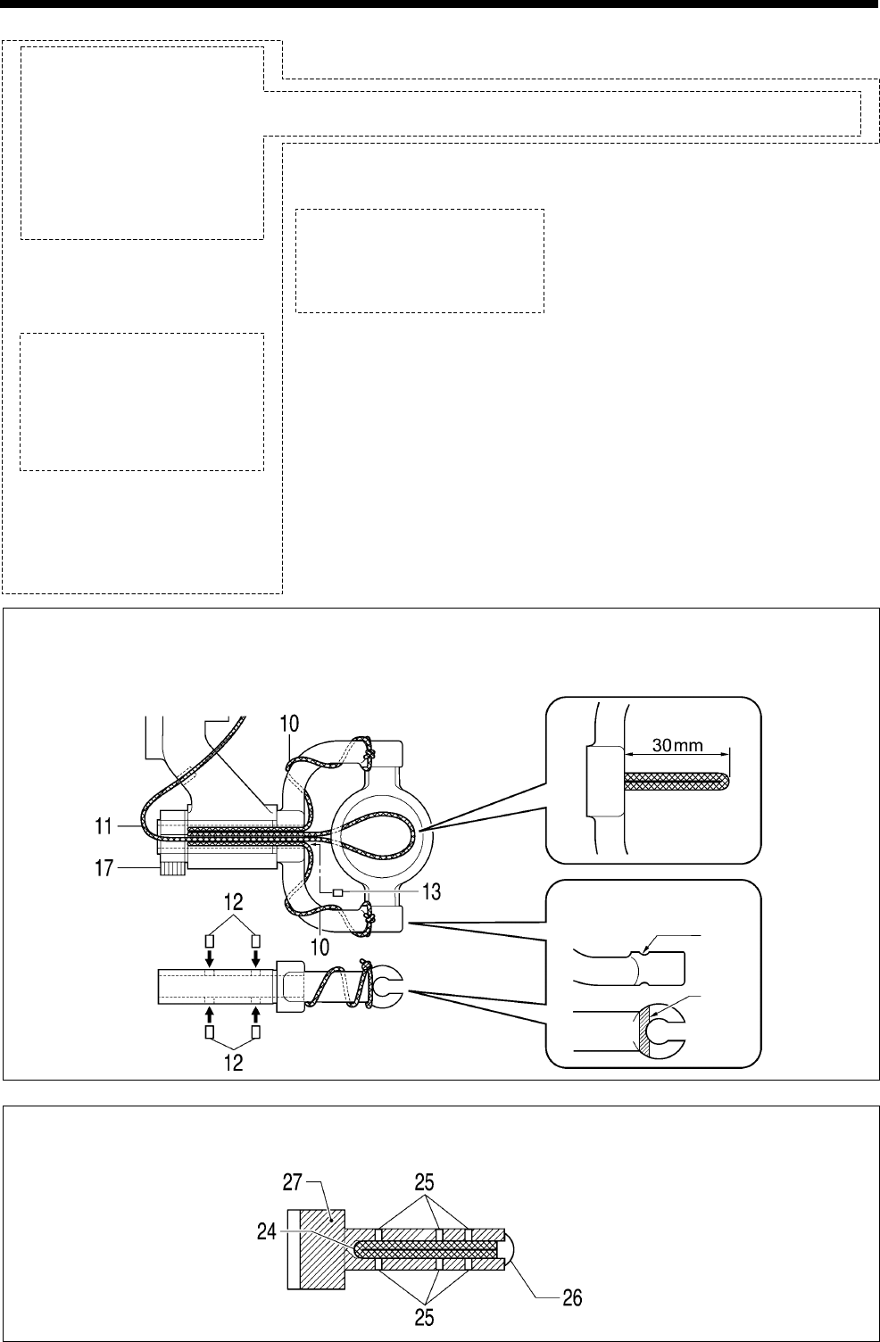
6. ASSEMBLY
RH-9820 60
1. Zigzag connecting rod
assembly
2. Shoulder screw
3. Nut
4. Zigzag crank screw
5. Nut
6. Plain washer
7. Nut
(Temporarily tighten)
8. Zigzag eccentric pin
9. Needle position control
plate assembly
10. Wicks [2 pcs]
11. Wick
12. Felts [4 pcs]
13. Felt
14. Zigzag horizon link
15. Zigzag lever
16. Needle bar clamp
17. Socket bolt
18. Zigzag driving lever
19. Socket bolt (Temporarily
tighten)
20. Needle bar block collar
21. Zigzag fork
22. Zigzag fork support shaft
23. Set screw
24. Wick
25. Felts [6 pcs]
26. Cap4
27. Zigzag coaxial rock shaft
28. Zigzag crank
29. Spacer
30. Set screws [2 pcs]
31. Needle bar block bracket
32. Screw
A Install the two wicks (10) and the wick (11) as shown in the illustration. Push in the felt (13) so that the
wick will not pull out, and then push in the four felts (12) so that they do not protrude from the end of the
shaft. After this, install the socket bolt (17) so that it faces as shown in the illustration.
B Install the wick (24) as shown in the illustration.
Next, push the six felts (25) into the end of the shaft so that they do not protrude.
0851B
Groove
Insert into the groove
and then tie.
0850B
Groove
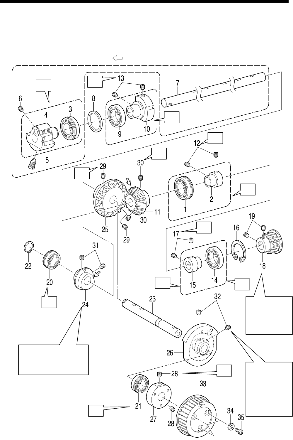
6. ASSEMBLY
RH-9820
61
6-4. Upper shaft mechanism
* Refer to the detailed descriptions on pages 62 and 63 for details on A to C in the illustration.
* For parts with screw stops, install so that the screw at the front in the turning direction is at the screw stop
position.
* Apply the grease specified by Brother (MOLYKOTE LONGTERM W2 manufactured by Dow Corning
Corporation) in the places indicated by .
0821B
Place the zigzag cam (24)
against the gear (25)
and then tighten. Refer to “7-29.
A
djustment of
the phase for
the take-up
roller cam”
when
assembling.
Place against
the bearing
collar (15) and
then tighten.
A
A
B
B
C
A
C
B
B
A
B
A
A
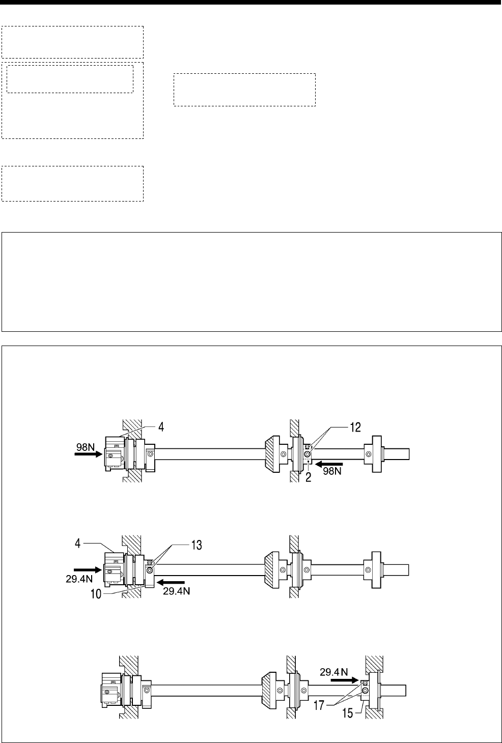
6. ASSEMBLY
RH-9820 62
1. Bearing
2. Bearing collar
3. Bearing
4. Upper shaft crank
5. Screw
6. Set screw
7. Upper shaft
8. Spacer
9. Bearing
10. Balance collar
11. Pinion
12. Set screws [2 pcs]
13. Set screws [2 pcs]
14. Bearing
15. Bearing collar
16. Internal retaining ring
17. Set screws [2 pcs]
18. Timing pulley assembly
19. Set screws [2 pcs]
20. Bearing
21. Bearing
22. Retaining ring C
23. Orthogonal shaft
24. Zigzag cam
25. Gear
26. Take-up cam roller
27. Pulley base
28. Set screws [2 pcs]
29. Set screws [2 pcs]
30. Set screws [2 pcs]
31. Set screws [2 pcs]
32. Set screws [2 pcs]
33. Pulley
34. Plain washers [3 pcs]
35. Screws [3 pcs]
A The outer circumferences of the bearings touch the sewing machine arm and the orthogonal shaft (23)
touch the inside of the bearings, so avoid removing them if possible.
If removing them, apply adhesive (Threebond 1373B) to the outer circumferences of the bearings, and
apply adhesive (Threebond 1401) to the inside of the bearing on the orthogonal shaft (23). Be sure to
wipe away any excess adhesive from the bearings at this time to avoid letting the adhesive get inside
the mechanism.
B Upper shaft and orthogonal shaft pressure adjustment
<Adjusting the pressure of the upper shaft>
1) While pushing the upper shaft crank (4) in the direction of the arrow with a force of 98 N, push the bearing
collar (2) in the direction of the arrow with a force of 98 N, and then tighten the two set screws (12).
2) While pushing the upper shaft crank (4) in the direction of the arrow with a force of 29.4 N, push the end
of the balance collar (10) against the upper shaft crank (4) with a force of 29.4 N, and then tighten the two
set screws (13).
3) While pushing the end of the bearing collar (15) in the direction of the arrow with a force of 29.4 N, tighten
the two set screws (17).
0822B
0823B
0824B
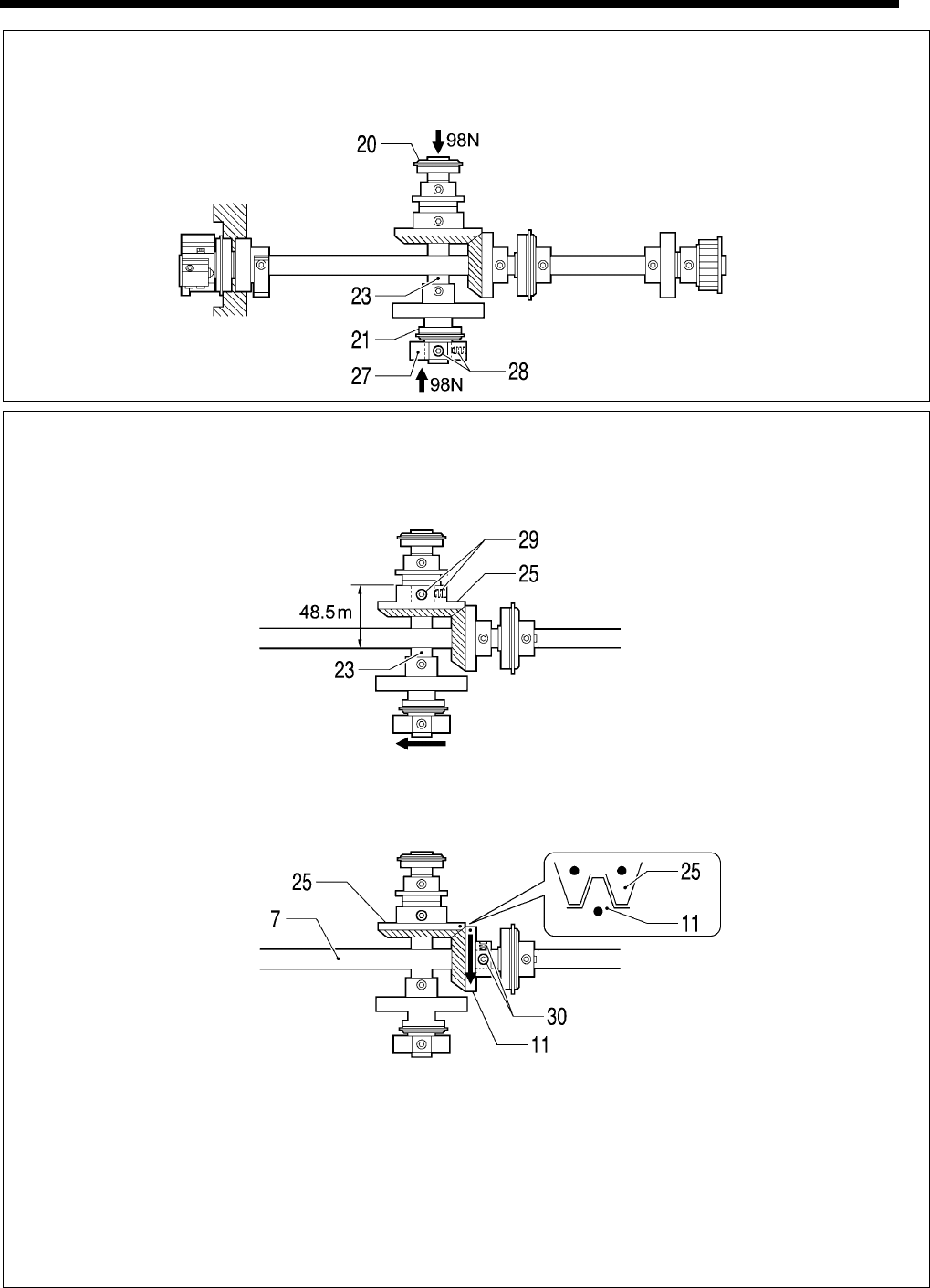
6. ASSEMBLY
RH-9820
63
<Adjusting the pressure of the orthogonal shaft>
While pushing the pulley base(27) in the direction of the arrow with a force of 98 N, push the orthogonal shaft
(23) in the direction of the arrow with a force of 98 N, and then tighten the two set screws (28).
* This adjustment should be carried out immediately after applying adhesive to the orthogonal shaft (23) and to
the inside of the bearing (20) and (21).
C Hypoid gear installation adjustment
1) Set the gear (25) to the position shown in the illustration, and then tighten the two set screws (29). Align the
set screw (29) at the front in the turning direction with the screw stop on the orthogonal shaft (23). (The arrow
shows the direction of rotation.)
2) Align the marks on the pinion (11) and the gear (25) as shown in the illustration. Next, align the set screw (30)
at the front of the pinion (11) in the turning direction with the screw stop on the upper shaft (7), and then
provisionally tighten the two set screws (30) so that the pinion (11) can still move in the axial direction. (The
arrow shows the direction of rotation.)
3) Push the pinion (11) against the gear (25) and adjust the backlash so that it is 0.05 mm or less, and then fully
tighten the two set screws (30).
<Adjusting the backlash>
Adjust the backlash so that it is zero at the point where it is at a minimum when the gear (25) is turned a full
rotation.
NOTE:
If the amount of backlash is too small, the rotation torque will increase and this will cause the gear (25) to
become worn. Furthermore, if the amount of backlash is too large, the operating noise will increase, so be
sure to adjust the backlash correctly.
0825B
0826B
0827B
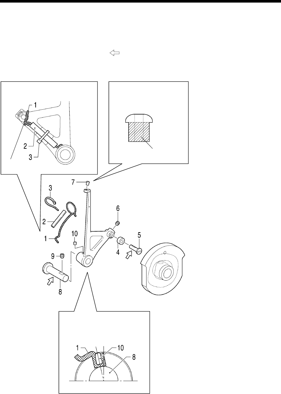
6. ASSEMBLY
RH-9820 64
6-5. Thread take-up mechanism
Insert the roller (4) into the groove in the thread take-up cam, and then insert the thread take-up L support
shaft (8).
* Apply the grease specified by Brother (MOLYKOTE LONGTERM W2 manufactured by Dow Corning
Corporation) in the places indicated by .
1. Wick
2. Oil tube
3. Fastening band
4. Roller
5. Roller shaft
6. Set screw
7. Thread guide
8. Thread take-up L support shaft
9. Set screw
10. Felt
A
pply adhesive (3M DP-125
clear) and then install.
* Be sure to wipe away any
excess adhesive.
Application location
0829B
0828B
0830B
Insert the wick (1) into the groove,
wind it around and then tie it.
Tie.
Push in the felt (10) so that the wick
(1) touches the thread take up leve
r
support shaft (8).
0831B
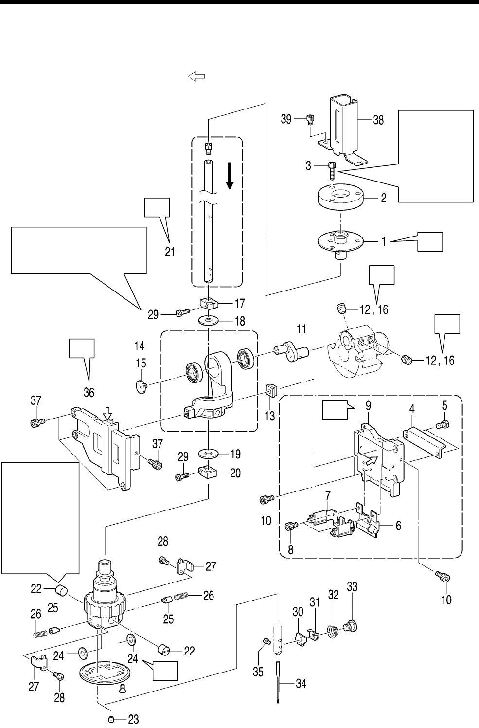
6. ASSEMBLY
RH-9820
65
6-6. Needle bar mechanism (2)
* Refer to the detailed descriptions on pages 66 to 68 for details on A to F in the illustration.
* Apply the grease specified by Brother (MOLYKOTE LONGTERM W2 manufactured by Dow Corning
Corporation) in the places indicated by .
Refer to “7-30.
A
djusting the
needle bar and
looper base
turning center”
when fully
tightening.
Refer to “7-6. Adjusting the
height of the needle bar” when
fully tightening.
Install so that
the needle bar
moves up and
down smoothly
and the amount
of play when
the needle bar
turns is as small
as
p
ossible.
0832B
B
A
F
F
E
D
C
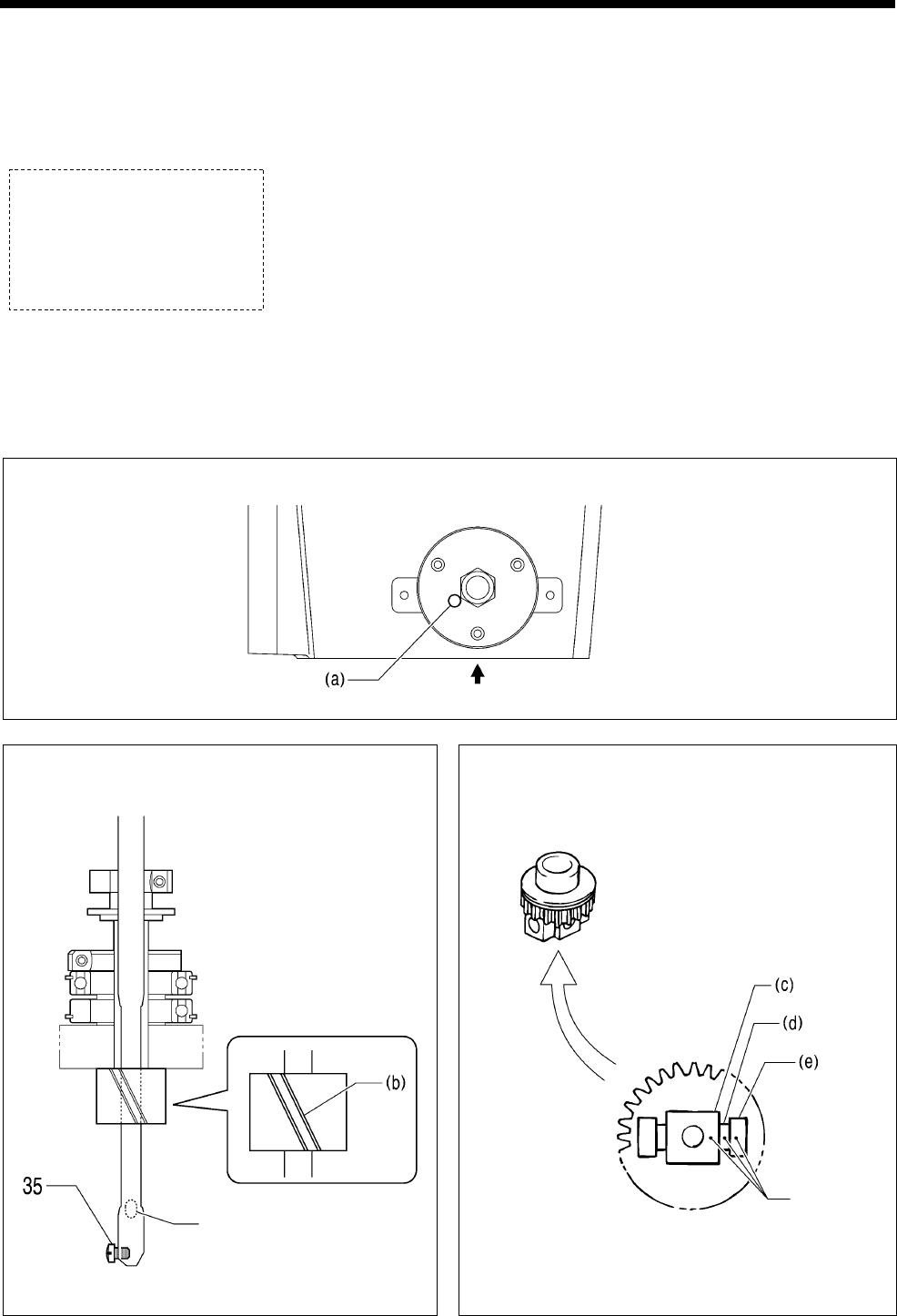
6. ASSEMBLY
RH-9820 66
1. Needle bar bush U
assembly
2. Needle bar bush holder
base C
3. Socket bolts [3 pcs]
(Temporarily tighten)
4. Oil plate
5. Screws [2 pcs]
6. Oil stopper
7. Felt holder assembly
8. Socket bolts [2 pcs]
9. Slide block guide D
10. Socket bolts [5 pcs]
11. Needle bar crank
12. Set screws [3 pcs]
(Temporarily tighten)
13. Slide block
14. Crank rod unit
15. Screw (Left-hand thread)
16. Set screws [3 pcs] (Fully
tighten)
17. Needle bar clamp
18. Plain washer
19. Plain washer
20. Needle bar clamp
21. Needle bar assembly L
(Insert from above)
22. Needle bar guide collars
[2 pcs]
23. Set screws [2 pcs]
24. Needle bar guide washers
[2 pcs]
25. Needle bar guides [2 pcs]
26. Needle bar guide springs
[2 pcs]
27. Needle bar guide support
plates [2 pcs]
28. Screws [2 pcs]
29. Needle bar bracket screws
[2 pcs] (Temporarily tighten)
30. Needle guide A
31. Needle thread holder plate A
32. Tension spring
33. Shoulder screw
34. Needle
35. Set screw, SM
36. Slide block guide F
37. Socket bolts [4 pcs]
38. Needle bar guard
39. Socket bolts [2 pcs]
A Be careful of the position of the hole (a) when assembling.
B Make sure that the direction of the groove (b)
is correct when assembling.
Viewed from the front
C Align the white painted marks on the needle
bar block (c), needle bar guide washer (d) and
needle bar gear (e) before installing.
0833B
A
t face plate
0835B
0834B
Thread path
hole is at the
back.
White
painted
marks
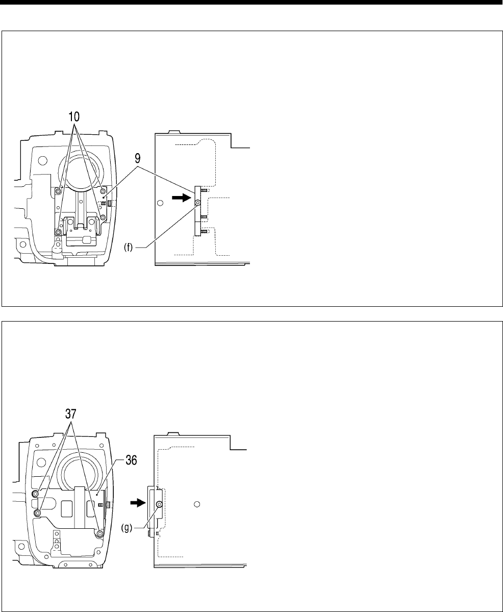
6. ASSEMBLY
RH-9820
67
D Slide block guide D installation
1) Provisionally tighten the four socket bolts (10)
so that the slide block guide D (9) can still
move.
2) While pushing the slide block guide D (9) gently
from the face plate side toward the arm
installation surface, tighten the fifth socket bolts
(10) (f) from the side of the arm.
3) Fully tighten the four socket bolts (10).
Face plate side Right side
E Slide block guide F installation
1) Provisionally tighten the three socket bolts (37)
so that the slide block guide F (36) can still
move.
2) While pushing the slide block guide F (36)
gently from the face plate side toward the arm
installation surface, tighten the fourth socket
bolts (37) (g) from the side of the arm.
3) Fully tighten the three socket bolts (37).
Face plate side Right side
0836B
0837B
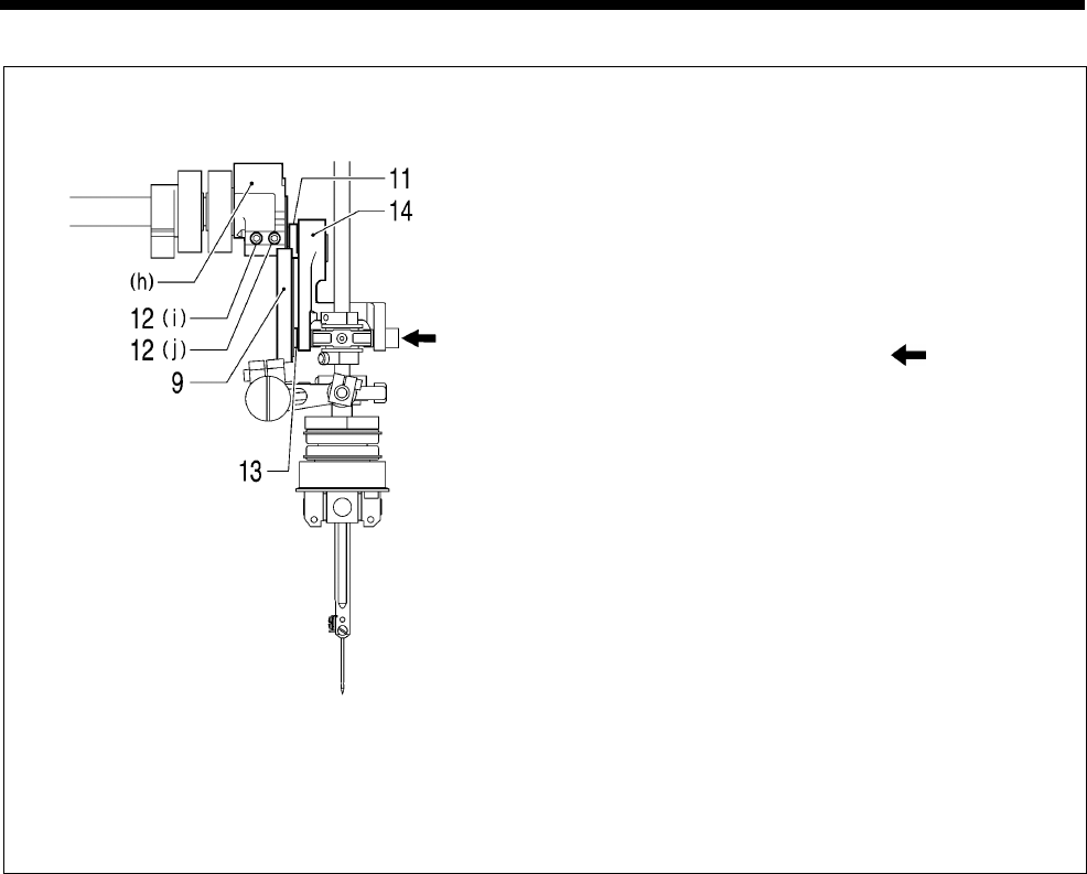
6. ASSEMBLY
RH-9820 68
F Needle bar crank forward/back adjustment
1) Align the screw stop of the needle bar crank
(11) with the side where the two set screws (12)
are on the upper shaft crank (h) (where the set
screw (12) (j) is), and then provisionally tighten
the two set screws (12) (i) and (j) so that the
needle bar crank (11) can still move back and
forth.
2) Pull out the crank rod unit (14) slightly.
3) Push the place indicated by to gently push
the Slide block (13) against slide block guide D
(9) so that the upper shaft crank (h) can still
turn easily, then tighten the set screw (12) (j)
through the hole in the side of the arm, and
then tighten the other set screw (12) (i)”. After
this, turn the upper shaft crank (h) and
provisionally tighten the third set screw (12) on
the opposite side.
* After assembling, check that the upper shaft
crank (h) turns easily. If the slide block (13) is
pushed too firmly, the upper shaft torque will
become stiffer.
0838B
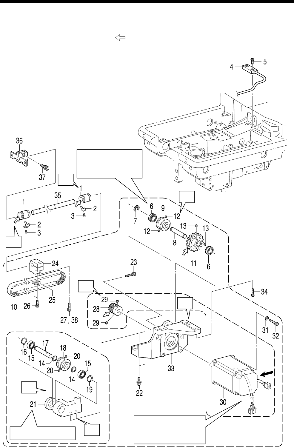
6. ASSEMBLY
RH-9820
69
6-7. Y feed mechanism
* Refer to the detailed descriptions on pages 70 to 72 for details on A to F in the illustration.
* Apply the grease specified by Brother (MOLYKOTE LONGTERM W2 manufactured by Dow Corning
Corporation) in the places indicated by .
NOTE:
After carrying out this procedure, be sure to adjust the Y home position while referring to “7-35. Adjusting
the needle up signal home position for the upper shaft and upper shaft motor”.
A
ssemble so that the
flanges are on the
inside.
Install so that the motor
connectors are facing as
indicated by the arrow.
Install the timing belt.
0839B
C
A
D
E
F
F
B
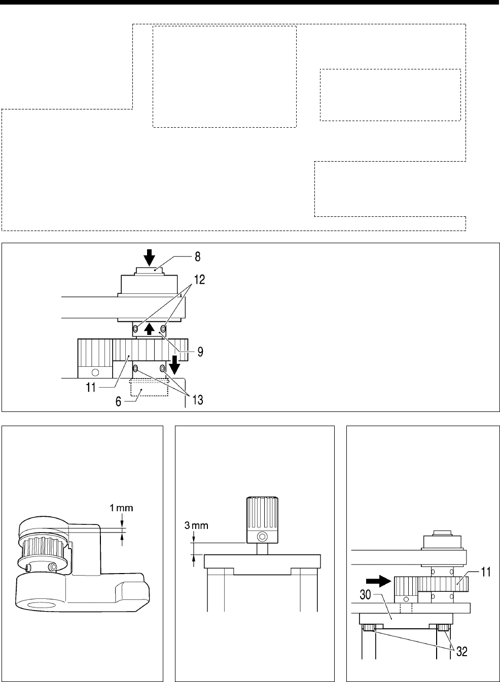
6. ASSEMBLY
RH-9820 70
1. Ball bearings [2 pcs]
2. Ball bearing stoppers
[2 pcs]
3. Screws [2 pcs]
4. Y position sensor
5. Screw
6. Ball bearings [2 pcs]
7. Retaining ring E
8. Y pulley shaft F
9. Y timing pulley assembly
10. Timing belt
11. Idler gear 40
12. Set screws [2 pcs]
13. Set screws [2 pcs]
14. Retaining rings C [2 pcs]
15. Ball bearings [2 pcs]
16. Retaining ring C
17. Y pulley shaft R
18. Y timing pulley assembly
19. Retaining ring C
20. Set screws [2 pcs]
21. Y pulley support
22. Socket bolts with washers
[2 pcs]
(Temporarily tighten)
23. Socket bolt
(Temporarily tighten)
24. Y driving shaft holder
25. Belt holder
26. Socket bolts [2 pcs]
27. Socket bolt
(Temporarily tighten)
28. Driving gear 20
29. Set screws [2 pcs]
30. Pulse motor Y assembly
31. Washers [4 pcs]
32. Socket bolts [4 pcs]
33. Y feed base
34. Socket bolts [3 pcs]
35. Y shaft
36. Y shaft holder
37. Socket bolt
38. Socket bolt
A
1) Push the Y pulley shaft F (8) and the Y timing
pulley assembly (9) in the direction of the arrow
so that there is no play in the parts, and then
tighten the two set screws (12).
2) Align the idler gear 40 (11) with the two set
screws (12) of the Y timing pulley assembly (9),
and then push it toward the side where the ball
bearing (6) are and tighten the two set screws
(13).
B Assemble as shown in the
illustration.
C Assemble as shown in the
illustration.
D Place the pulse motor Y
assembly (30) against the
idler gear 40 (11) so that
the amount of backlash is
0.03 mm or less, and then
tighten the four socket
bolts (32).
0840B
0843B
0842B
0841B
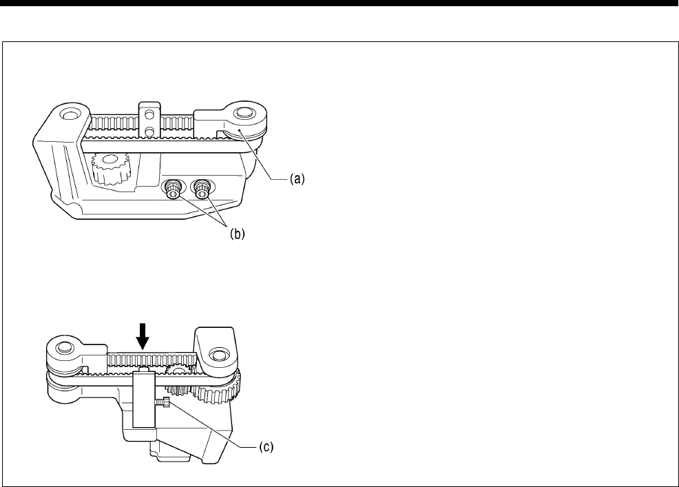
6. ASSEMBLY
RH-9820
71
E Belt tension adjustment
Repeat steps1 to 3 to adjust the belt tension until it
is within the ranges given below.
・ When using a new belt: 80 - 90 N
・ When reusing an old belt: 60 - 70 N
1) Loosen the two screws (b) of the Y pulley
support assembly (a).
2) Use the adjustment screw (c) to adjust the belt
tension.
3) Tighten the two screws (b) of the Y pulley
support assembly (a).
* Be sure to use a belt tension gauge to measure
the belt tension, and measure at the position
shown in the illustration.
* The belt tension gauge should be set to
measure a unit weight of 0.04 kg/m, a belt width
of 10 mm and a span length of 120 mm.
0844B
0845B
Measurement position
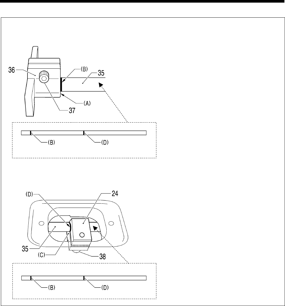
6. ASSEMBLY
RH-9820 72
F Standard installation of motor unit
<Y shaft and Y shaft holder installation positions>
Align the end (A) of the Y shaft holder (36) and
the reference line (B) on the Y shaft (35), and
then tighten the socket bolt (37).
<Y shaft and Y driving shaft holder installation positions>
Align the end (C) of the Y driving shaft holder
(24) and the reference line (D) on the Y shaft
(35), and then tighten the socket bolt (38).
0846B
0847B
0848B
0847B
Front
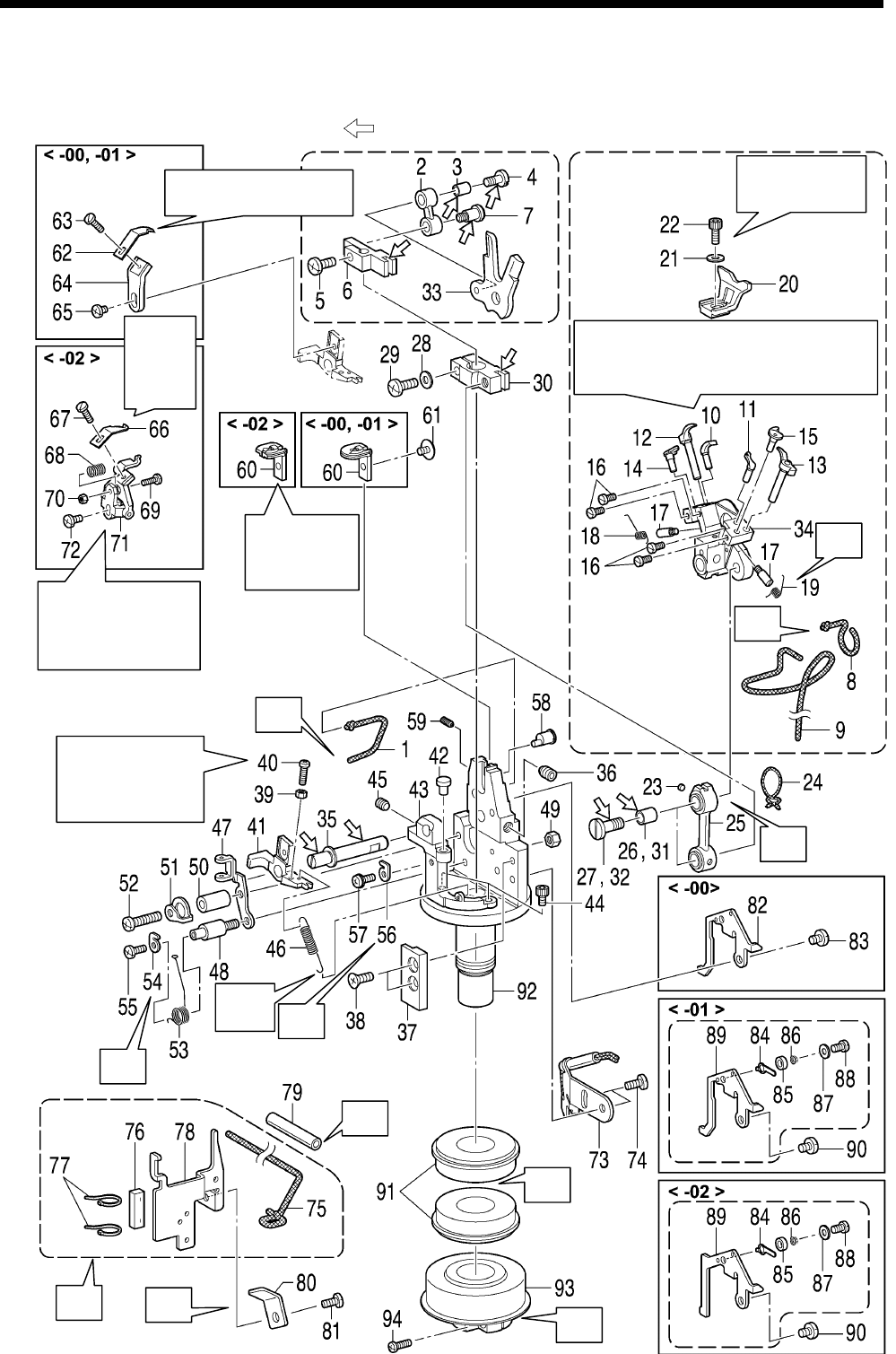
6. ASSEMBLY
RH-9820
73
6-8. Looper base mechanism
* Refer to the detailed descriptions on pages 75 to 78 for details on A to F in the illustration.
* Apply the grease specified by Brother (MOLYKOTE LONGTERM W2 manufactured by Dow Corning
Corporation) in the places indicated by .
1093B
Refer to “7-24-2. Adjusting
the upper movable knife”.
C
D
E
F
R
e
f
er
t
o
“7-24-2.
A
djusting
the upper
movable
knife”.
J
K
Refer to “7-28.
A
djusting the position
of the lower thread
presser <-02
specifications only>”.
Refer to “7-24-3.
A
djusting the
position of the thread
trimmer lever
bracket”.
Refer to “7-11
A
djusting the
height of the
throat plate”.
Refer to “7-8.
A
djusting the
needle guard”.
Refer to “7-1. Adjusting the heights of the
spreaders and loopers” and “7-7. Adjusting
the clearance between the loopers and
needle”.
Longe
r
end
A
H
I
B
G

6. ASSEMBLY
RH-9820 74
1. Wick
2. Spreader cam link
3. Collar
4. Shoulder screw
5. Screw
(Temporarily tighten)
6. Spreader link base
7. Shoulder screw
8. Wick
9. Wick
10. Eye looper
11. Looper R
12. Spreader L
13. Spreader R
14. Spreader stopper L
15. Spreader stopper R
16. Screw [4 pcs]
(Temporarily tighten)
17. Spring guide shaft
18. Twist spring L
19. Twist spring R
20. Needle guard U
21. Plain washer
22. Socket bolt
(Temporarily tighten)
23. Felt
24. Wick
25. Looper link
26. Collar
27. Shoulder screw
28. Plain washer
29. Screw (Temporarily tighten)
30. Looper link clamp
31. Collar
32. Shoulder screw
33. Spreader driving cam
34. LS holder base
35. Holder presser shaft
36. Set screw
37. LS slide guide
38. Plain washer [2 pcs]
39. Nut
40. Screw (Temporarily tighten)
41. Thread trimmer lever
bracket
42. Pin
43. Support shaft base
44. Socket bolts [2 pcs]
45. Set screw
46. Spring
47. Thread guide plate
48. Spring guide shaft
49. Nut
50. Collar
51. L thread take-up spring
support
52. Screw (Temporarily tighten)
53. Thread take-up spring
54. L thread take-up spring
support
55. Screw (Temporarily tighten)
56. L thread take-up spring
support
57. Screw with washer
58. Vertical pin
59. Set screw
(Temporarily tighten)
60. Throat plate
61. Screw (Temporarily tighten)
<-00 and -01 specifications only>
62. Upper movable knife A
63. Screw (Temporarily tighten)
64. Upper movable knife base
65. Screw (Temporarily tighten)
<-02 specifications only>
66. Upper movable knife B
67. Screw (Temporarily tighten)
68. Spring
69. Screw
70. Nut
71. Lower thread presser J
assembly
72. Screw (Temporarily tighten)
73. Looper base oil plate assembly
74. Screws [2 pcs]
75. Wick
76. Felt
77. Fastening bands [2 pcs]
78. Gimp thread waste plate
79. Oil tube
80. Cord holder
81. Screw
<-00 specifications only>
82. Gimp thread guide C
83. Screw
<-01 and -02 specifications only>
84. Gimp thread clamp plate
85. Collar
86. Spring
87. Plain washer
88. Screw
89. Gimp thread guide C
<Gimp thread guide C-J for -02
specifications>
90. Screw
91. Ball bearings [2 pcs]
92. Looper base
93. Looper pulley assembly
94. Screw
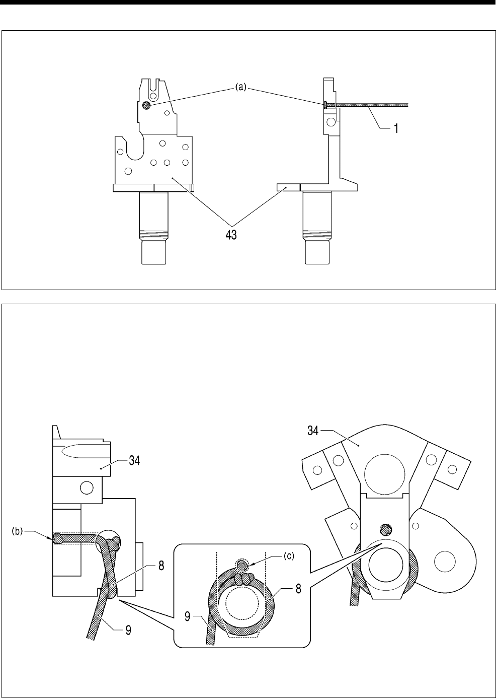
6. ASSEMBLY
RH-9820
75
A Tie one end of the wick (1) once, and then push that end into the hole (a) in the support shaft base (43).
* Push in so that the knot does not protrude from the hole (a).
(Viewed from the front) (Viewed from the right)
B
1) Tie one end of the wick (8) once, and then push that end into the hole (b) in the LS holder base (34).
* Push in so that the knot does not protrude from the hole (b).
2) Tie the other end of the wick (8) to one end of the wick (9), and then wind them around the LS holder
base (34) as shown in the illustration.
* Tie the wicks twice to form the knot.
* Wind so that the knot is directly below the hole (c) and so that it does not protrude to the outside.
* Wind the wick (8) and the wick (9) so that they are positioned as shown in the illustration.
1185B
(Viewed from the left) (Viewed from the front)
1184B
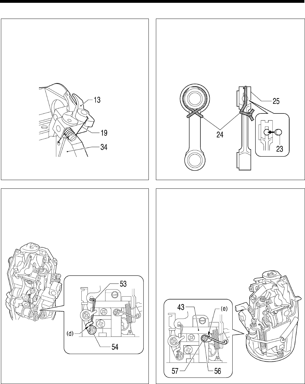
6. ASSEMBLY
RH-9820 76
C
Hook the longer end of twist spring R (19) onto
spreader R (13), and pass the shorter end through
the hole in the LS holder base (34) as shown in the
illustration.
D
1) Push the felt (23) into the hole in the looper link
(25).
2) Tie the wick (24) around the looper link (25) as
shown in the illustration.
* Make a double knot in the wick (24), and
then cut off the excess length so that the
ends are 2 - 3 mm in length.
E
Hook the thread take-up spring (53) onto the hook
(d) of the L thread take-up spring support (54) as
shown in the illustration.
F
1) Hook the wick onto the hook (e) of the L thread
take-up spring support (56) as shown in the
illustration.
2) Raise the end of the hook (e) of the L thread
take-up spring support (56) so that it touches the
support shaft base (43), and then tighten the
screw with washer (57) at that position.
* This will prevent the wick from pulling away.
1096B
1094B 1095B
1097B
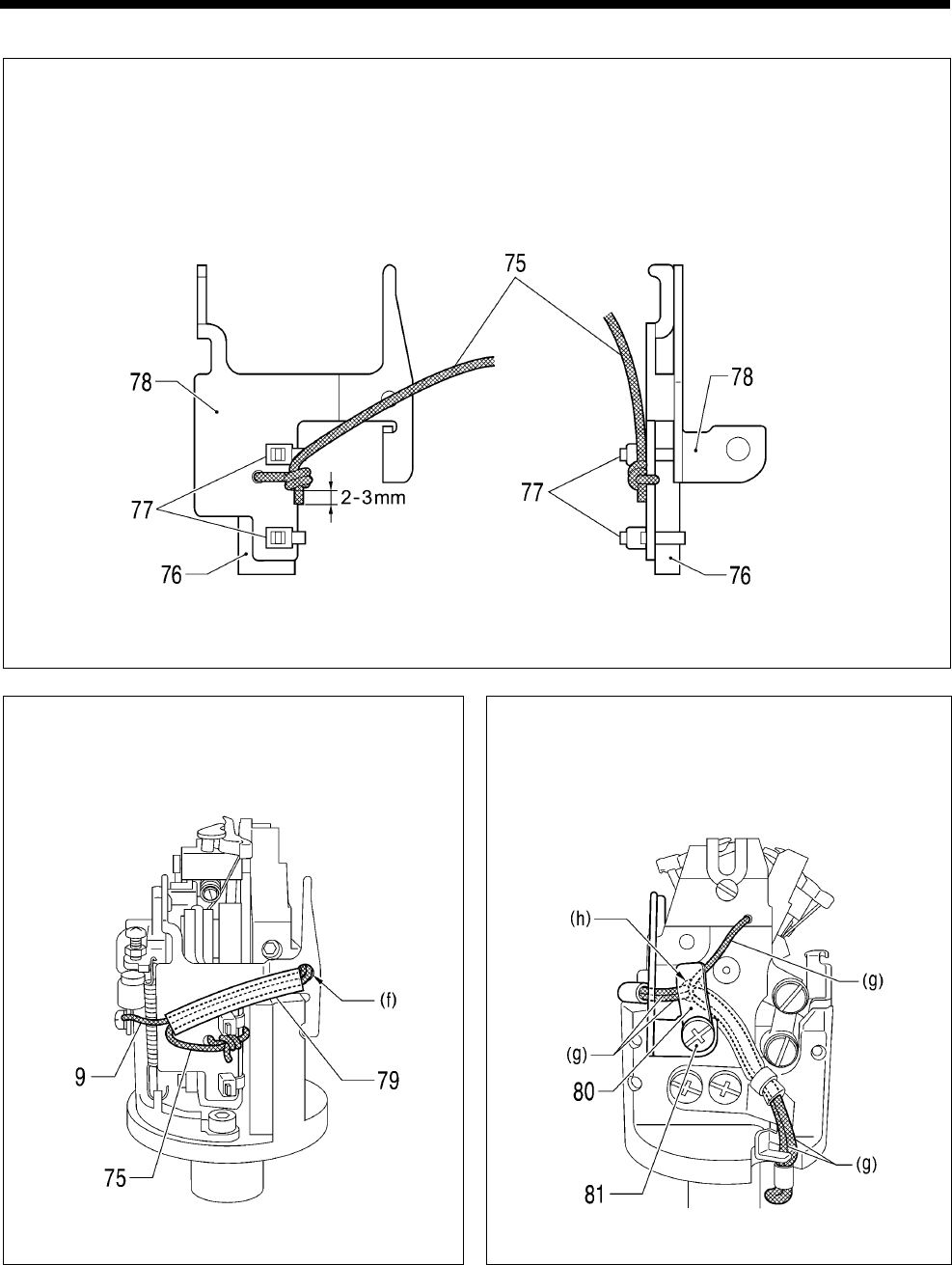
6. ASSEMBLY
RH-9820
77
G
1) Tie the wick (75) around the wick release plate (78) as shown in the illustration.
* Make a double knot in the wick, and then set the wick so that the distance from the knot to the end is
as shown in the illustration, and cut off any excess length.
2) Install the felt (76) to the wick release plate (78) with the two cable ties (77).
* Cut the ends of the two cable ties (77) so that a length of 0 to 2 mm remains.
(Viewed from the front) (Viewed from the right)
H Pass the wick (9) and the wick (75) through the
oil tube (79) as shown in the illustration, and
then pass them through the hole (f).
I Push the five wicks (g) into the hole (h) as
shown in the illustration, and then install the
cord presser (80) and secure it by tightening
the screw (81).
1186B
1187B 1188B
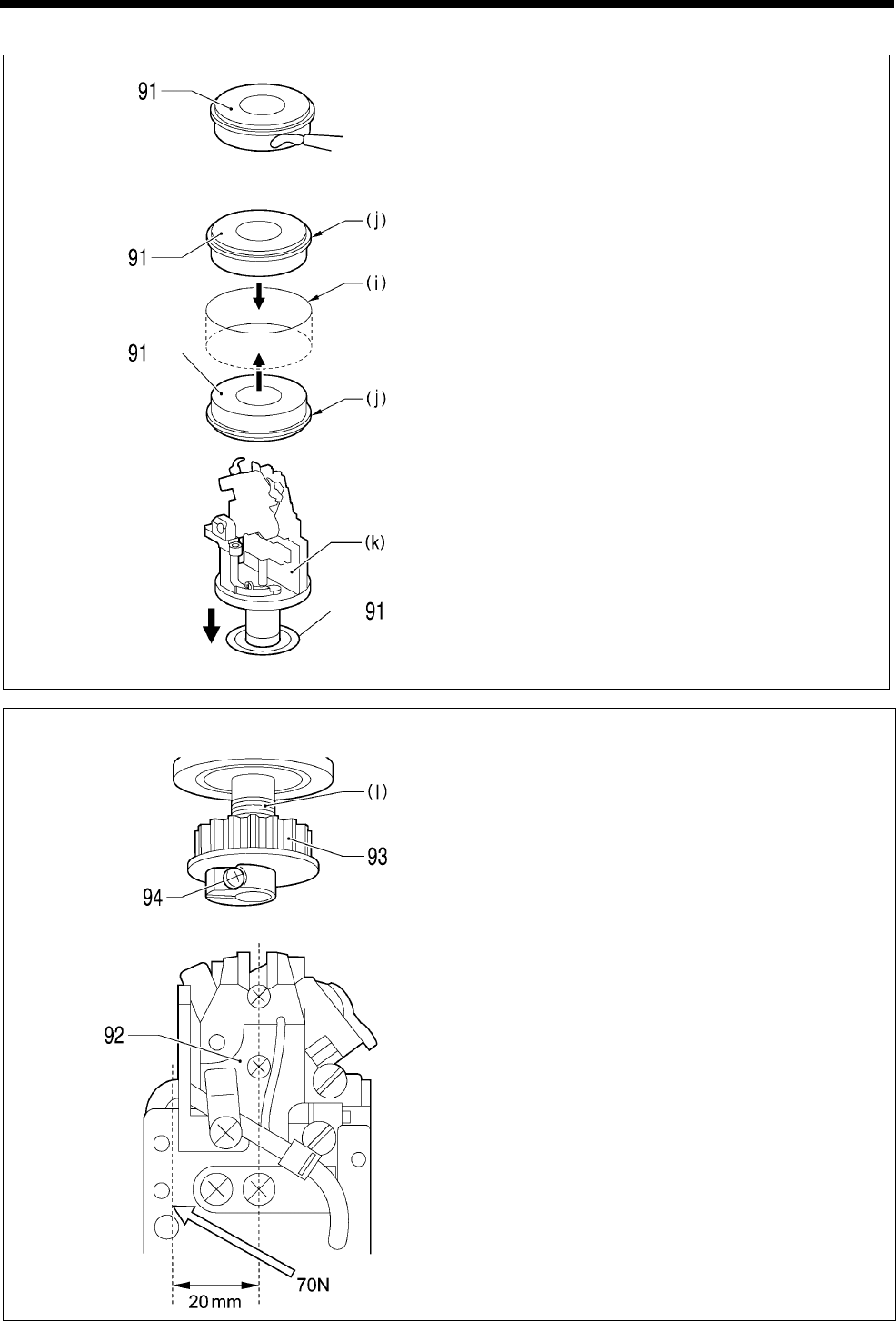
6. ASSEMBLY
RH-9820 78
J
1) Apply adhesive (Threebond 1373B) to the
outer circumferences of the two ball bearings
(91).
2) Insert the two ball bearings (91) into the top
and bottom of the looper base mounting hole
(i) in the bed.
* Insert the two ball bearings (91) securely
until their surfaces (j) are fully touching.
* Wipe away any excess adhesive at this
time.
3) Insert the looper base assembly (k).
K Looper base pressure adjustment
1) Gently screw the looper pulley assembly (93)
onto the threaded section (l) of the looper base.
2) Secure the looper pulley assembly (93) so that
it will not turn, and then push the back of the
looper base (92) at a point 20 mm to the left of
center with a force of 70 N.
3) Tighten the screw (94).
1098B
1099B
1100B
1101B
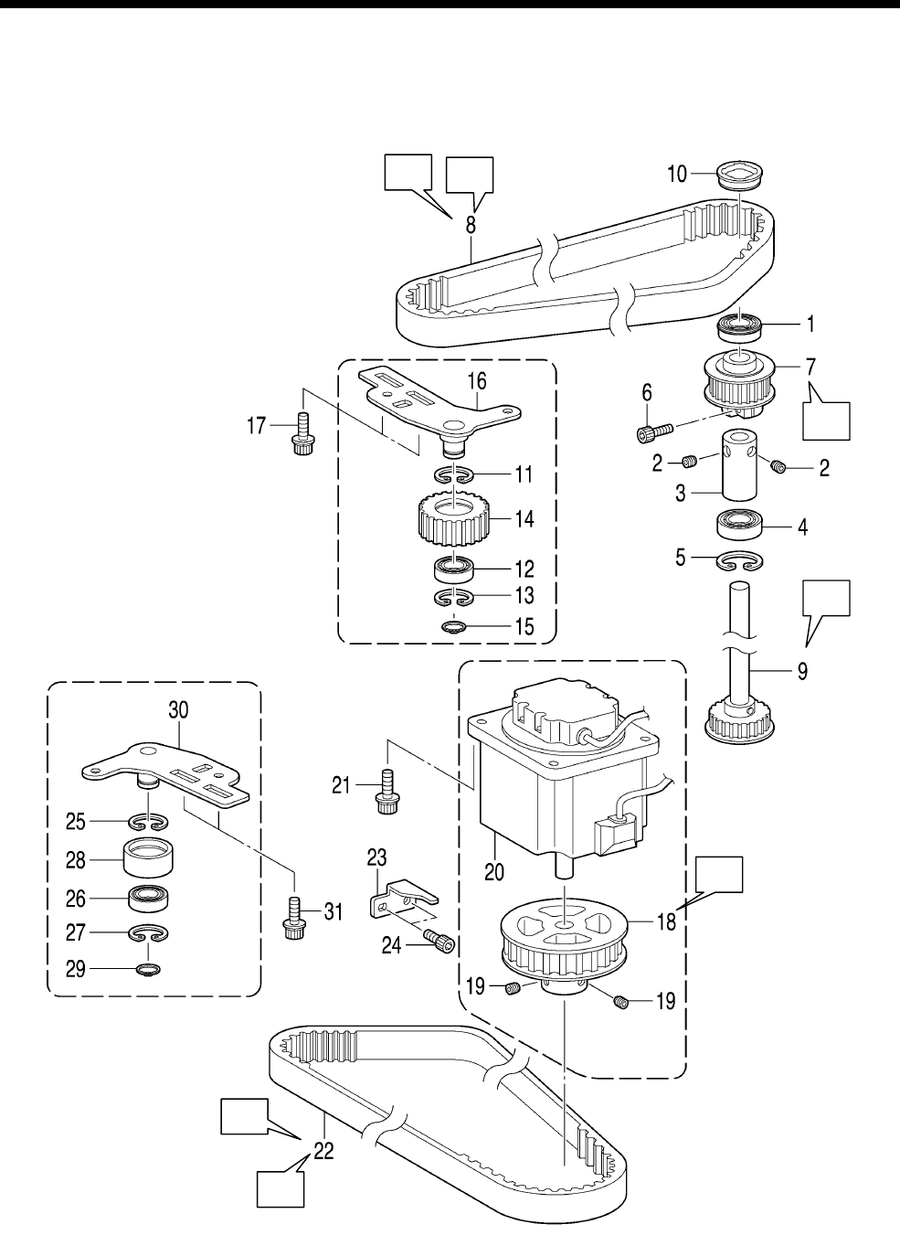
6. ASSEMBLY
RH-9820
79
6-9. Needle bar rocking mechanism
* Refer to the detailed descriptions on pages 80 to 84 for details on A to G in the illustration.
0922B
A
B
C
D
G
E
F
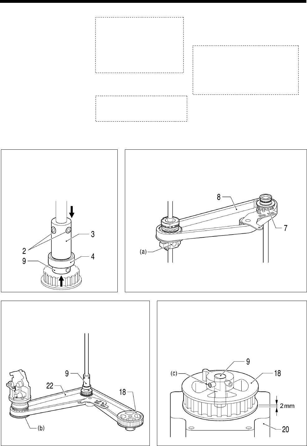
6. ASSEMBLY
RH-9820 80
1. Bearing
2. Set screws [2pcs]
(Temporarily tighten)
3. Set screw collar
4. Bearing
5. Internal retaining ring
6. Socket bolt (Temporarily
tighten)
7. Vertical shaft timing pulley
U assembly
8. Timing belt
9. Driving looper shaft
assembly
10. Rubber cap
11. Internal retaining ring
12. Bearing
13. Internal retaining ring
14. Tension pulley U
15. Retaining ring C
16. Timing pulley holder
assembly
17. Socket bolts with washers
[2 pcs]
18. Theta M pulley assembly
19. Set screws [2 pcs]
20. Pulse motor assembly R
21. Socket bolts with washers
[4 pcs]
22. Timing belt
23. Motor stopper
24. Socket bolts [2 pcs]
25. Internal retaining ring
26. Bearing
27. Internal retaining ring
28. Tension pulley
29. Retaining ring C
30. Timing pulley holder assembly
31. Socket bolts with washers
[2 pcs]
A Push the driving looper shaft
assembly (9) from the lowered to
the raised position, then push the
set screw collar (3) down to clamp
the bearing (4), and then tighten
the two set screws (2).
B Place the timing belt (8) onto the needle bar gear block (a)
and the vertical shaft timing pulley U assembly (7).
C Place the timing belt (22) onto the looper base
(b), driving looper shaft assembly (9) and the
theta M pulley assembly (18).
D Align the screw (c) at the left side of the theta
M pulley assembly (18) with the screw stop on
the driving looper shaft assembly (9). In
addition, set the clearance between the theta M
pulley assembly (18) and pulse motor
assembly R (20) to 2 mm.
0923B 0924B
0926B
0925B
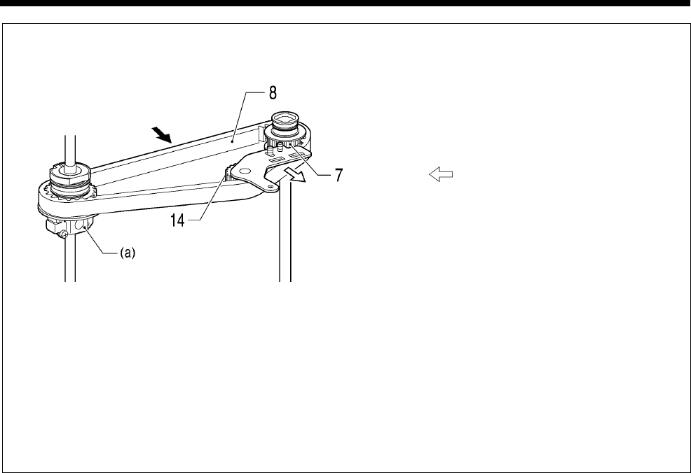
6. ASSEMBLY
RH-9820
81
E Belt tension adjustment for needle bar gear block belt
1) Place the timing belt (8) onto the needle bar
gear block (a) and the vertical shaft timing
pulley U assembly (7), and then provisionally
install tension pulley U (14) so that it is gently
pressing against the timing belt (8).
2) Pull tension pulley U (14) in the direction of the
arrow to adjust the belt tension so that it is
within the ranges given below.
・ When using a new belt: 80 - 90 N
・ When reusing an old belt: 60 - 70 N
* Be sure to use a belt tension gauge to measure
the belt tension, and measure at the position
shown in the illustration.
* The belt tension gauge should be set to
measure a unit weight of 0.04 kg/m, a belt width
of 10 mm and a span length of 219 mm.
NOTE:
If you do not have a belt tension gauge, adjust
so that the amount of deflection is
approximately 3 mm when a pressure of 5 N is
applied to the middle of the span (the
measurement position shown in the illustration).
Measurement position
0927B
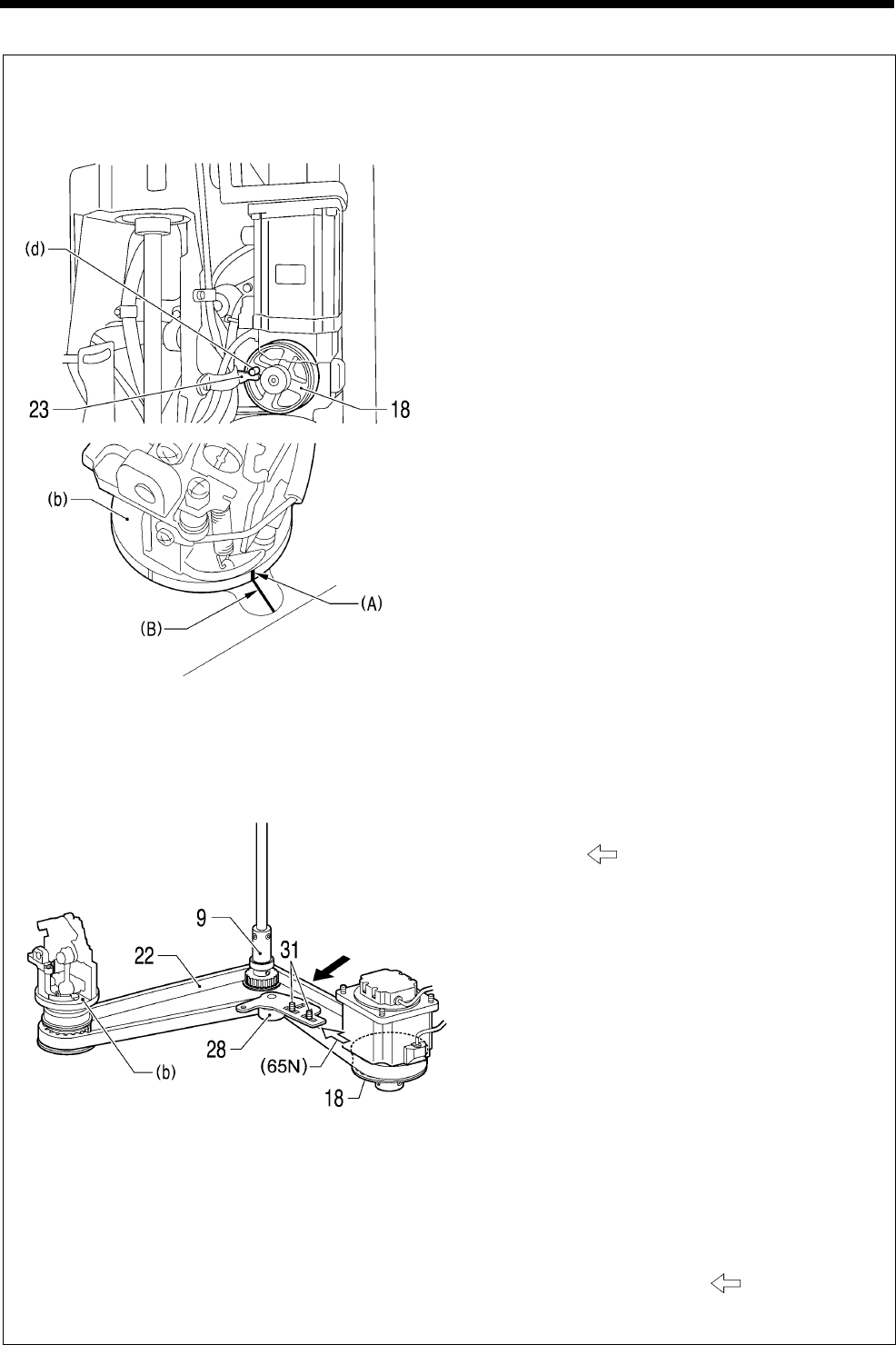
6. ASSEMBLY
RH-9820 82
F Belt tension adjustment for driving looper belt
<Standard installation when belt is tensioned>
Attach the timing belt (22) so that the distance
from reference line (A) (for installation: 65 °
position) on the looper base (b) to reference line
(B) on the bed is 5 mm or less when (d) of the
theta M pulley assembly (18) is touching against
the motor stopper (23), and then adjust tension
pulley (28) to the appropriate tension.
<Belt tension adjustment>
1) Place the timing belt (22) onto the looper base
(b), driving looper shaft assembly (9) and theta
M pulley assembly (18), and then provisionally
install the tension pulley (28) so that it is gently
pressing against the timing belt (22).
2) Pull the tension pulley (28) in the direction of
the arrow to adjust the belt tension so that
it is within the ranges given below.
・ When using a new belt: 80 - 90 N
・ When reusing an old belt: 60 - 70 N
3) Check that the mechanism is at the <Standard
installation when belt is tensioned> position
given above at this time. If the reference lines
are more than 5 mm apart, readjust the
mechanism.
* Be sure to use a belt tension gauge to measure
the belt tension, and measure at the position
shown in the illustration.
* The belt tension gauge should be set to
measure a unit weight of 0.04 kg/m, a belt width
of 10 mm and a span length of 136 mm.
NOTE:
If you do not have a belt tension gauge, use a
push-pull gauge to push tension pulley (28) in
the direction of the arrow with a force of 65
N, and then tighten the two socket bolts with
washers (31).
Measurement
position
1197B
0928B
0929B
Measurement position
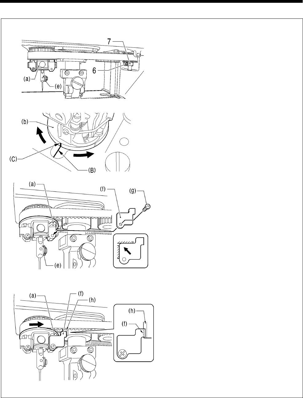
6. ASSEMBLY
RH-9820
83
G Looper base and needle bar gear block position adjustment
1) Loosen the socket bolt (6) of the vertical shaft
timing pulley U assembly (7).
2) Turn the needle bar gear block (a) until the
socket bolt (6) of vertical shaft timing pulley U
assembly (7) is toward the front when the
thread guide (e) on the needle bar is at the
back.
3) Turn the looper base (b) until reference line (B)
on the bed is aligned with reference line (C) (0°:
left side) on the looper base.
4) Install the positioning gauge (f) to the end of
the needle bar gear block (a) with the screw
(g). (The thread guide (e) on the needle bar
should be all the way in [on the right side in
the illustration].)
* Install the positioning gauge (f) so that it is
pushed up to the top-left.
5) Turn the needle bar gear block (a) in the
direction of the arrow until the positioning
gauge (f) touches the end (h) of the cutter
driving bushing.
* The underside of the positioning gauge (f)
should touch the end (h).
0930B
0931B
1195B
1196B
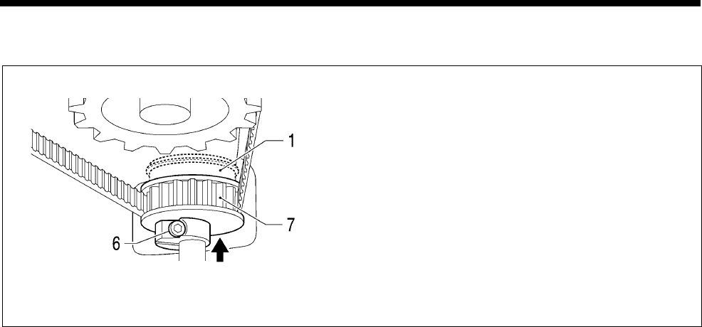
6. ASSEMBLY
RH-9820 84
6) Push the vertical shaft timing pulley U assembly
(7) up gently until it touches the bearing (1),
and then tighten the socket bolt (6).
0932B
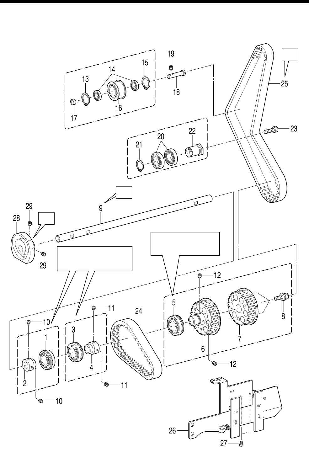
6. ASSEMBLY
RH-9820
85
6-10. Lower shaft mechanism
* Refer to the detailed descriptions on pages 86 to 89 for details on A to C in the illustration.
0933B
B
A
C
Press-fit into the arm
after assembling.
Press-fit into the arm
after assembling.
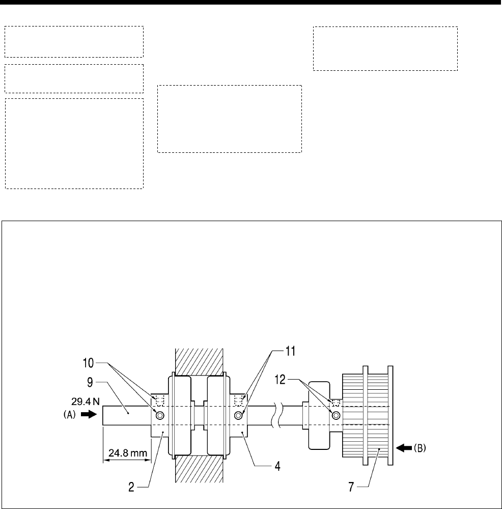
6. ASSEMBLY
RH-9820 86
1. Bearing
2. Bearing collar
3. Bearing
4. Bearing collar
5. Bearing
6. Lower shaft tension
pulley A
7. Lower shaft tension
pulley B
8. Socket bolts with
washers [3 pcs]
9. Lower shaft
10. Set screws [2 pcs]
11. Set screws [2 pcs]
12. Set screws [2 pcs]
13. Internal retaining ring
14. Bearings [2 pcs]
15. Internal retaining ring
16. Idler pulley
17. Collar
18. Idler pulley shaft
19. Set screw
20. Bearings [2 pcs]
21. Retaining ring C
22. Tension pulley collar
23. Socket bolt (Temporarily tighten)
24. Timing belt (For lower shaft -
upper shaft motor) (Temporarily
tighten)
25. Timing belt
(For upper shaft - lower shaft)
26. Lower shaft cover assembly
27. Screws [2 pcs]
28. Lower shaft cam
29. Set screws [2 pcs]
(Temporarily tighten)
A Lower shaft pressure adjustment
1) Set so that the amount of protrusion is 24.8 mm, and then tighten the two set screws (10) of the bearing
collar (2) against the lower shaft (9). (This is to prevent the shaft from protruding when installing the lower
shaft cam (28).)
2) While pushing the lower shaft (9). in the direction of arrow (A) with a force of 29.4 N, tighten the two set
screws (11) of the bearing collar (4).
3) Push the back of lower shaft tension pulley B (7) gently in the direction of arrow (B) and tighten the two
set screws (12).
0934B
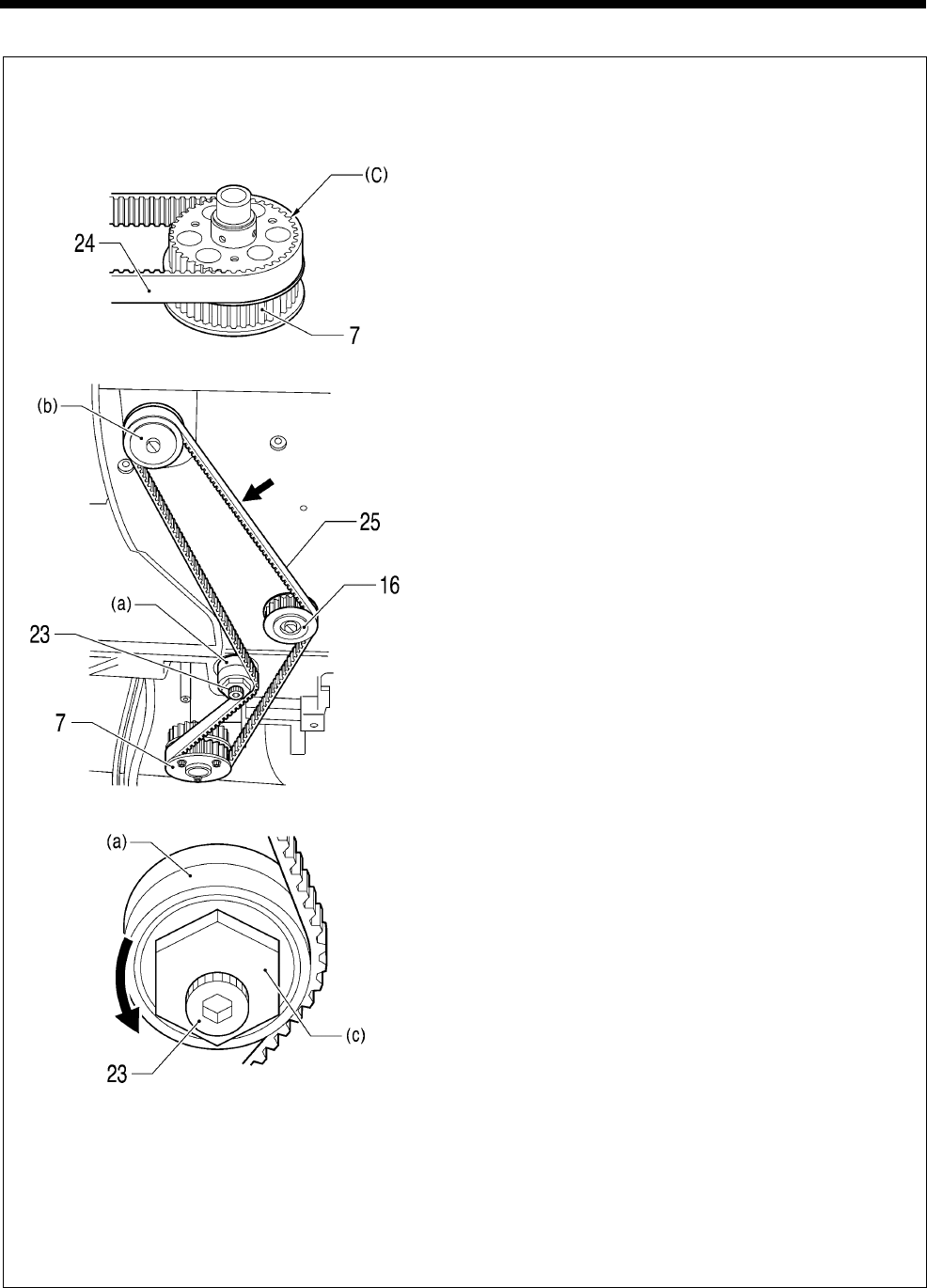
6. ASSEMBLY
RH-9820
87
B Belt (upper shaft - lower shaft) installation and belt tension adjustment
<If the belt (lower shaft – upper shaft motor) is not installed (if installing the upper shaft motor later)>
1) Place the timing belt (24) (for lower shaft –
upper shaft motor) into the groove (C) in lower
shaft tension pulley B (7).
2) Loosen the socket bolt (23) of the tension
pulley assembly (a).
3) Place the timing belt (25) (for upper shaft -
lower shaft) onto the upper shaft timing pulley
(b), idler pulley (16), lower shaft tension pulley
B (7) and tension pulley assembly (a).
4) Use a spanner to turn the hexagonal part (c) of
the eccentric shaft of the tension pulley
assembly (a) in the direction of the arrow to
adjust the belt tension to within the ranges
given below, and then tighten the socket bolt
(23).
・ When using a new belt: 170 - 190 N
・ When reusing an old belt: 140 - 170 N
* Be sure to use a belt tension gauge to measure
the belt tension, and measure at the position
shown in the illustration.
* The belt tension gauge should be set to
measure a unit weight of 0.04 kg/m, a belt width
of 15 mm and a span length of 198 mm.
NOTE:
If you do not have a belt tension gauge, adjust so
that the amount of deflection is approximately 2
mm when a pressure of 5N is applied to the middle
of the span (the measurement position shown in
the illustration).
Measurement position
0935B
0936B
0937B
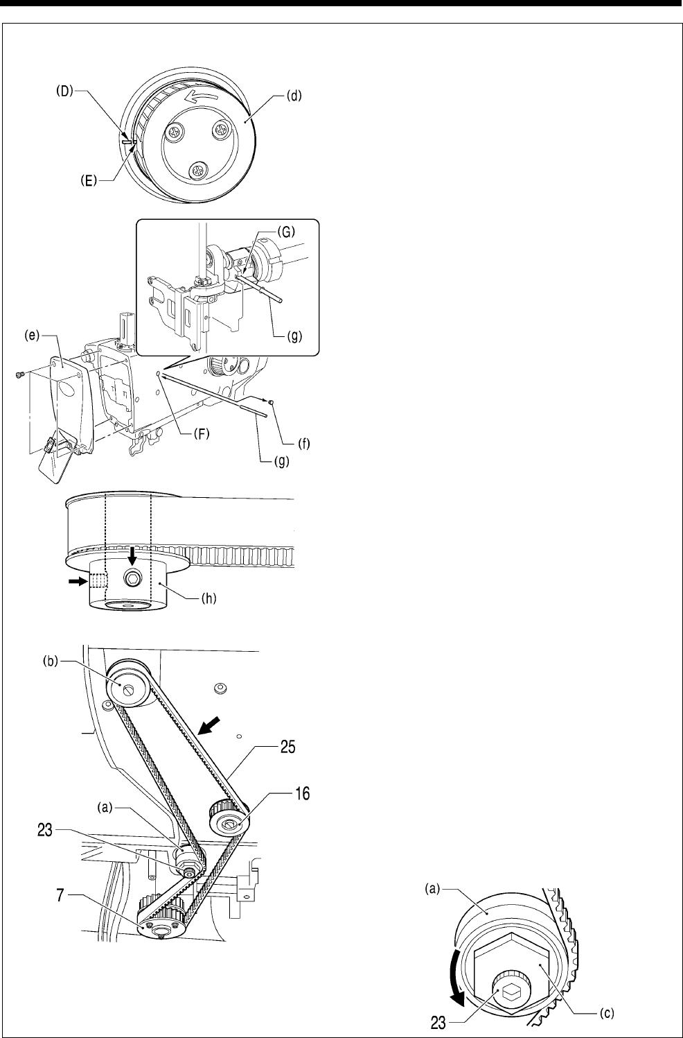
6. ASSEMBLY
RH-9820 88
<If the belt (lower shaft – upper shaft motor) is installed (if the upper shaft motor is already installed)>
1) Turn the upper shaft pulley (d) to the needle up
stop position.
(Align the pulley groove (E) with the arm
reference line (D).)
2) Remove the face plate (e) and the rubber cap
(f), and then insert the accessory pin (g) into
the groove (G) of the crank from the hole (F) in
the arm to secure the upper shaft. (Upper shaft
0° position)
3) Hold the timing pulley (h) of the upper shaft
motor still with your hand so that the screw on
the timing pulley (h) is in the position shown in
the illustration, and then place the timing belt
(25) (for upper shaft - lower shaft) onto the
upper shaft timing pulley (b), idler pulley (16),
lower shaft tension pulley B (7) and tension
pulley assembly (a).
4) Use a spanner to turn the hexagonal part (c) of
the eccentric shaft of the tension pulley
assembly (a) in the direction of the arrow to
adjust the belt tension to within the ranges
given below, and then tighten the socket bolt
(23).
・ When using a new belt: 170 - 190 N
・ When reusing an old belt: 140 - 170 N
* Be sure to use a belt tension gauge to measure
the belt tension, and measure at the position
shown in the illustration.
* The belt tension gauge should be set to
measure a unit weight of 0.04 kg/m, a belt width
of 15 mm and a span length of 198 mm.
0941B
0938B
0939B
0940B
Measurement position
1198B
6. ASSEMBLY
RH-9820
89
C Lower shaft provisional installation position
* This position is the provisional position for the lower shaft until the procedure in “7-5. Adjusting the looper
stroke” is carried out.
1) Turn the upper shaft pulley (d) to the needle up
stop position.
(Align the pulley groove (E) with the arm
reference line (D).)
2) Align the index mark (I) of the lower shaft cam
(28) with the hole (H) in the bed.
3) Push the lower shaft cam (28) against the end
of the bearing collar (2), and then provisionally
tighten the two set screws (29).
Should be no clearance. 0941B
0942B
0943B
6. ASSEMBLY
RH-9820 90
6-11. Looper mechanism
* Refer to the detailed descriptions on the next page for details on A in the illustration.
* Apply the grease specified by Brother (MOLYKOTE LONGTERM W2 manufactured by Dow Corning
Corporation) in the places indicated by .
1. Felt
2. Roller
3. Roller shaft
4. Set screw
5. Wick
6. Wick
7. Oil tube
8. Wick
9. Oil tube
10. Looper tube clamp B
11. Screw
12. Looper tube clamp A
13. Screw
14. Looper driving plate
15. Shafts [2 pcs]
16. Set screws [2 pcs]
17. Looper lever
18. Looper lever shaft
19. Set screws [2 pcs]
20. Looper driving shaft bracket
21. Looper driving shaft
22. Socket bolt
23. Screw (Temporarily tighten)
A
Check that
the looper
driving plate
(14) turns
smoothly
through 360°
with no play.
1076B
Refer to “7-4. Adjusting
the needle and looper
timing”.
6. ASSEMBLY
RH-9820
91
A Install the wicks as shown in the illustration.
(Viewed from directly above)
(Viewed from the left) (Viewed from the front)
1104B
1103B
1102B
・ Tie in two knots.
・ Cut the ends at a
length 2 mm from the
knots.
Fold twice and pass
through the hole.
・ Tie in two knots.
・ Cut the ends at a
length 2 mm from the
knots.
・ Tie once.
・ Pass the knot through
the tube.
・ Tie once.
・ Pass the knot through
the tube.
(Clearance)
(Viewed from underneath)
6. ASSEMBLY
RH-9820 92
6-12. Spreader mechanism
* Refer to the detailed descriptions on the next page for details on A and B in the illustration.
* Apply the grease specified by Brother (MOLYKOTE LONGTERM W2 manufactured by Dow Corning
Corporation) in the places indicated by .
1. Felt
2. Spreader tube clamp
3. Screw
4. Wick
5. Oil tube
6. Fastening bands [2 pcs]
7. Wick
8. Retaining ring C
9. Shaft
10. Retaining ring C
11. Shaft
12. Set screws [2 pcs]
13. Slide blocks [2 pcs]
14. Spreader lever A
15. Spreader link shaft
16. Spreader lever B
17. Spreader lever shaft
18. Set screws [2 pcs]
19. Eccentric pin
20. Screw (Temporarily tighten)
21. Plain washers [2 pcs]
22. Screws [2 pcs] (Temporarily tighten)
23. Screw (Fully tighten)
A
The larger
bevelled
surface should
be on the
inside.
Refer to “7-10.
A
djusting the
spreader timing”.
1105B
B
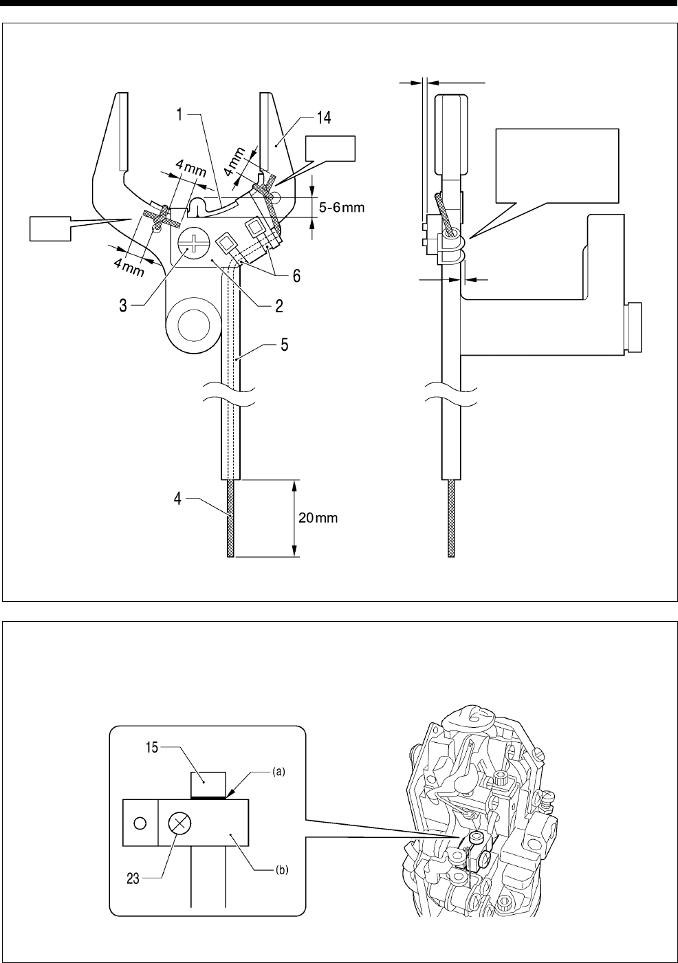
6. ASSEMBLY
RH-9820
93
A Install the wicks as shown in the illustration.
B Align the top of the spreader link base (b) with the reference line (a) on the spreader link shaft (15), and
then tighten the screw (23).
1027B
1028B
Tie.
Tie.
Cut at 0 - 2 mm.
Tighten so that the
two fastening bands
(6) are not lifted up.
*
1
*
1
*
1
Set to 1
mm or less.
*1: Cut the ends at a
length 4 mm from
the knots.
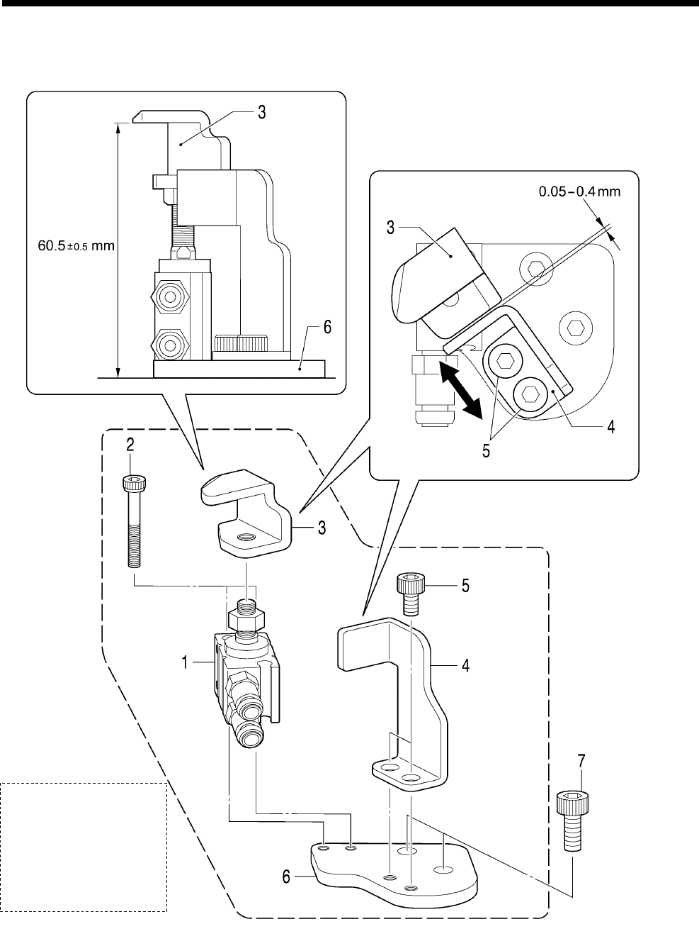
6. ASSEMBLY
RH-9820 94
6-13. Upper thread trimmer mechanism
* Install in the positions shown in the illustration.
1. Cylinder assembly
2. Socket bolts [2 pcs]
3. Hammer
4. Hammer guide plate
5. Socket bolts [2 pcs]
6. Cylinder setting plate
7. Socket bolts [2 pcs]
0985B
(When at
maximum
extension)
Clearance:
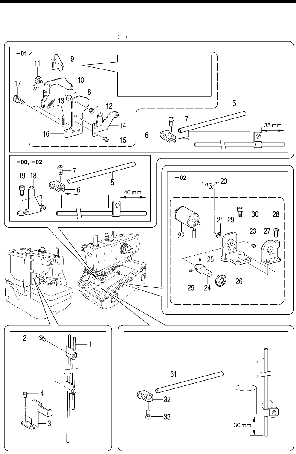
6. ASSEMBLY
RH-9820
95
6-14. Threading mechanism
* Apply the grease specified by Brother (MOLYKOTE LONGTERM W2 manufactured by Dow Corning
Corporation) in the places indicated by .
Tighten the shoulder screw (11)
followed by the nut (12) so that the
gimp thread take-up driving plate (9)
and the gimp thread tale-up plate (10)
move smoothly with no play.
0944B
Make sure the direction is correct.
Make sure the direction is
correct.

6. ASSEMBLY
RH-9820 96
1. 2 pedal thread guide pipe
2. Screws [2 pcs]
3. Pipe clamp plate
4. Screws [2 pcs]
5. Thread guide pipe
6. Thread guide pipe support
7. Screw
<-01 specifications only>
8. Washer
9. Gimp thread take-up
G-E plate
10. Gimp thread take-up guide
plate
11. Shoulder screw
12. Nut
13. Springs [2 pcs]
14. Gimp thread guide
15. Screw
16. Gimp thread take-up
G-holder
17. Socket bolts [2 pcs]
<-00 and -02 specifications only>
18. Gimp thread guide J
19. Socket bolts [2 pcs]
<-02 specifications only>
20. O Ring [2 pcs]
21. Retaining ring E
22. Solenoid
23. Screws [2 pcs]
24. Gimp thread shaft
25. Set screws [2 pcs]
26. Tension disc
27. Gimp thread clamp
28. Screws [2 pcs]
29. Gimp thread clamp plate
30. Socket bolts [2 pcs]
31. Thread guide pipe
32. Thread guide pipe support
33. Screw
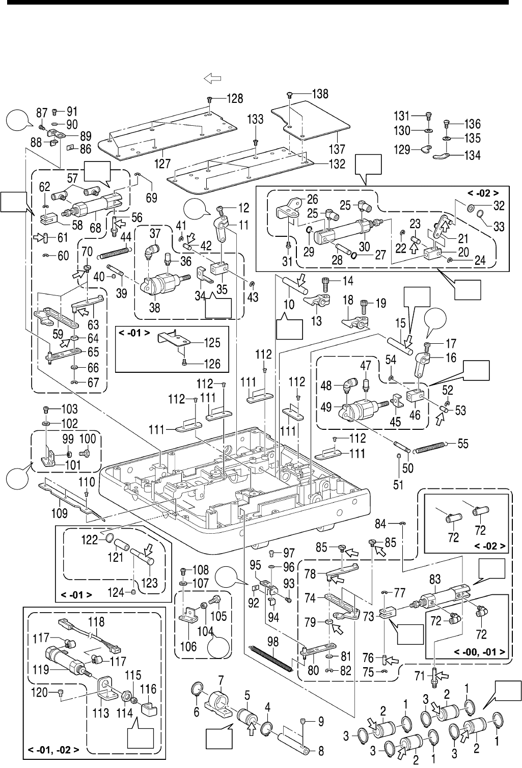
6. ASSEMBLY
RH-9820
97
6-15. Feed base mechanism
* Refer to the detailed descriptions on pages 102 and 103 for details on A to K in the illustration.
* Apply the grease specified by Brother (MOLYKOTE LONGTERM W2 manufactured by Dow Corning
Corporation) in the places indicated by .
6-15-1. Feed base
0986B
*2
*1
*1
*3
*2
*3
I
J
G
G
C
H
E
H
F
A
B
K
D

6. ASSEMBLY
RH-9820 98
1. Retaining ring C [4 pcs]
2. Ball bearings [4 pcs]
3. Retaining ring C [4 pcs]
4. Retaining ring C
5. Ball bearing
6. Retaining ring C
7. Y bearing
8. Y guide shaft
9. Set screws [2 pcs]
10. Clamp lever shaft
11. Clamp driving lever
12. Screw (Temporarily tighten)
13. Crank lever B
14. Socket bolt
15. Clamp lever shaft
16. Clamp driving lever
17. Screw (Temporarily tighten)
18. Crank lever B
19. Socket bolt
20. Cylinder rod
21. Auxiliary clamp
connecting rod
22. Retaining ring E
23. Cylinder rod pin
24. Retaining ring E
25. Joint [2 pcs]
26. Auxiliary clamp S holder
27. Retaining ring E
28. Pin
29. Retaining ring E
30. Cylinder
31. Screw
32. Washer
33. Retaining ring C
34. Spring hook
35. Clamp cylinder rod
36. Air bolster
37. Joint
38. Cylinder
39. Clamp cylinder support
40. Set screw
41. Retaining ring E
42. Cylinder rod pin
43. Retaining ring E
44. Spring
45. Spring hook
46. Clamp cylinder rod
47. Air bolster
48. Joint
49. Cylinder
50. Clamp cylinder support
51. Set screw
52. Retaining ring E
53. Cylinder rod pin
54. Retaining ring E
55. Spring
56. Cylinder screw
57. Joint [2 pcs]
58. Opening cylinder rod
59. Opening driving lever L
assembly
60. Retaining ring E
61. Cylinder rod pin B
62. Retaining ring E
63. Fulcrum lever plate
64. Slide block
65. Rocker lever
66. Washer
67. Retaining ring E
68. Cylinder
69. Retaining ring E
70. Shoulder screw [3 pcs]
71. Cylinder screw
72. Joints [2 pcs]
73. Opening cylinder rod
74. Opening driving lever R
assembly
75. Retaining ring E
76. Cylinder rod pin B
77. Retaining ring E
78. Fulcrum lever plate
79. Slide block
80. Rocker lever
81. Washer
82. Retaining ring E
83. Cylinder
84. Retaining ring E
85. Shoulder screw [3 pcs]
86. Speed nut
87. Screw (Temporarily tighten)
88. Stopper plate
89. Opening stopper plate
90. Washer
91. Screw (Temporarily tighten)
92. Speed nut
93. Screw (Temporarily tighten)
94. Stopper plate
95. Opening stopper plate
96. Washer
97. Screw (Temporarily tighten)
98. Spring
99. Nut (Temporarily tighten)
100. Bolt
101. Opening cylinder stopper
102. Spring washer
103. Screws [2 pcs]
104. Nut (Temporarily tighten)
105. Bolt
106. Opening cylinder stopper
107. Spring washer
108. Screws [2 pcs]
109. Plate guide B
110. Flat screws [3 pcs]
111. Plate guides A [5 pcs]
112. Flat screws [10 pcs]
113. Thread trimmer cylinder
support plate
114. Nut
115. Nut
116. Thread trimmer cylinder claw
117. Joint
118. Sensor
119. Cylinder
120. Socket bolts [2 pcs]
121. Collar
122. Retaining ring C
123. Gimp thread take-up guide
shaft
124. Set screw
125. Feed base plate spring
126. Screws [2 pcs]
Route the air tubes and harnesses
here. (Refer to pages 99 - 101.)
127. Feed base cover L
128. Flat screws [6 pcs]
129. Plate presser
130. Bending washer
131. Shoulder screw
132. Feed base cover R
133. Flat screws [6 pcs]
134. Plate presser
135. Bending washer
136. Shoulder screw
137. Feed base cover U
138. Truss screws [2 pcs]
*1:Refer to “7-18. Adjusting the work clamp lift amounts”.
*2:Refer to “7-21. Adjusting the cloth opening amounts”.
*3:Refer to “7-20. Adjusting the positions of the work clamp plates”.
<-02 specifications only>
<-01 and -02 specifications only>
<-01 specifications only>
6. ASSEMBLY
RH-9820
99
Routing the air tubes and harnesses <-00 specifications>
The air tubes and harnesses are numbered as shown in the illustration. Check the number of each air tube and
harness to make sure that they are routed correctly as shown in the illustration.
0987B
6. ASSEMBLY
RH-9820 100
Routing the air tubes and harnesses <-01 specifications>
The air tubes and harnesses are numbered as shown in the illustration. Check the number of each air tube and
harness to make sure that they are routed correctly as shown in the illustration.
0988B
6. ASSEMBLY
RH-9820
101
Routing the air tubes and harnesses <-02 specifications>
The air tubes and harnesses are numbered as shown in the illustration. Check the number of each air tube and
harness to make sure that they are routed correctly as shown in the illustration.
0989B
6. ASSEMBLY
RH-9820 102
A Turn the feed base (a) upside down. Place the
four retaining rings C (1) onto one side of the
four ball bearings (2), then apply adhesive
(Threebond 1373B) to the four ball bearings
(2) and then insert them into the four holes (b).
* Wipe away any excess adhesive at this
time.
* Install so that the layout of the balls (c) is in
an “X” pattern on the installation surface as
shown in the illustration.
B Place the retaining rings C (4) onto one side of
the ball bearing (5), then apply adhesive
(Threebond 1373B) to the ball bearing (5) and
then insert it into the Y bearing (7).
* Wipe away any excess adhesive at this
time.
* Install so that the layout of the balls (d) is in
an “X” pattern on the installation surface as
shown in the illustration.
C Assemble as shown in the illustration.
D Assemble as shown in the illustration.
E Assemble as shown in the illustration.
F Assemble as shown in the illustration.
0995B
0990B
0991B
0997B
0994B
0996B
(When at maximum retraction)
(When at maximum retraction)
(When at maximum retraction)
(最縮時)
0992B
0993B
Installation
surface
Installation
surface
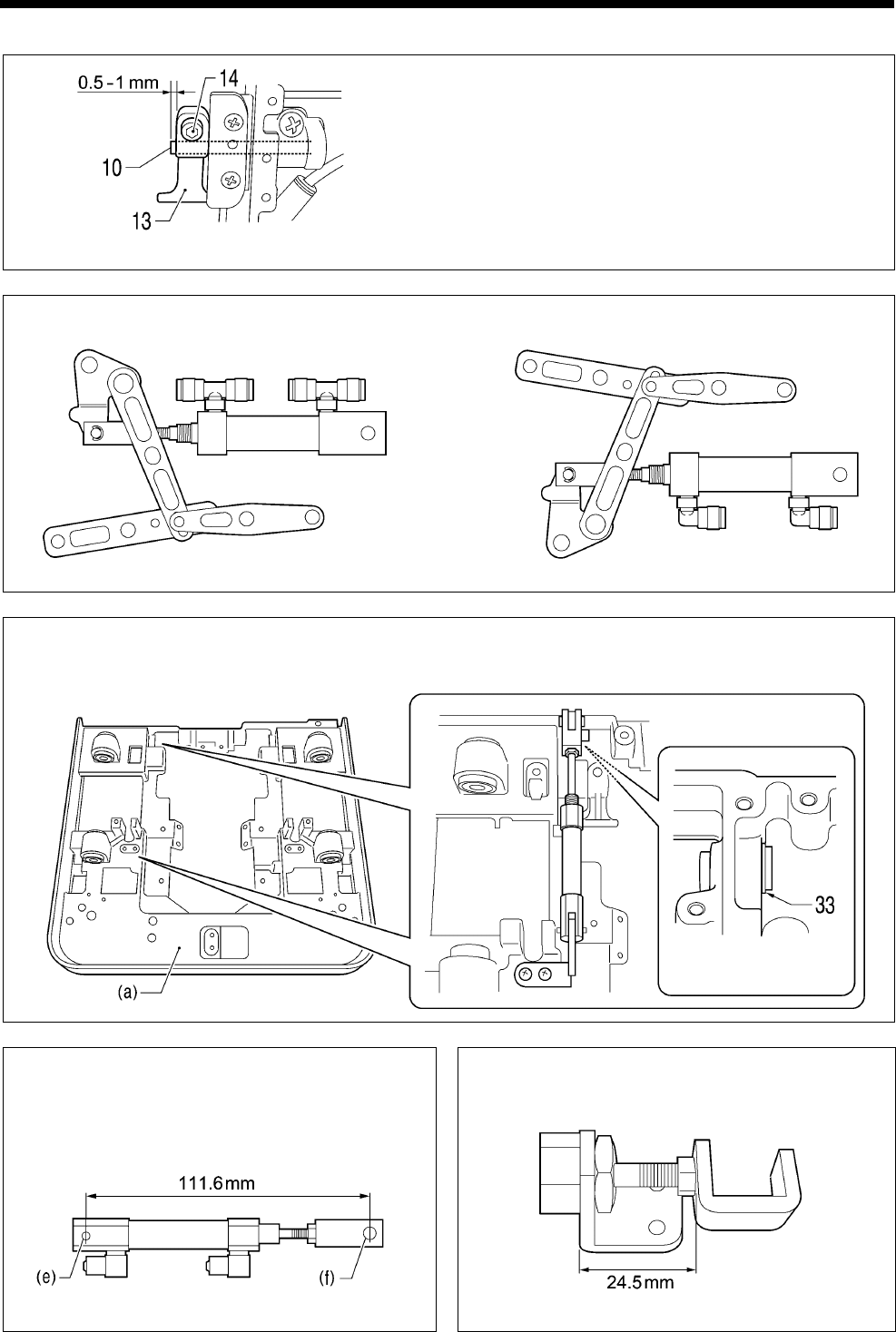
6. ASSEMBLY
RH-9820
103
G
Set the clamp lever shaft (10) so that the amount
of protrusion at the end is as shown in the
illustration, then assemble crank lever B (13) so
that there is no clearance between it and the inside
of the clamp lever shaft (10), and then tighten the
socket bolt (14).
(The left side is the same.)
(Right side )
H Assemble while referring to the finished assembly diagram shown below.
(Left side ) (Right side )
I <For -02 specifications only>
Install to the feed base (a) as shown in the illustration below.
J <For -02 specifications only>
Install so that the centers of the pin holes (e)
and (f) are at the distance shown in the
illustration.
K <For -01 and -02 specifications only>
Install at the distance shown in the illustration.
0999B
1000B
1002B
1001B
(When at maximum retraction)
(When at maximum retraction)
(Viewed from underside)
0998B
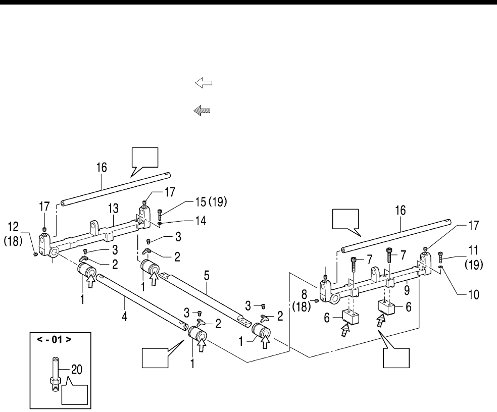
6. ASSEMBLY
RH-9820 104
6-15-2. X feed shaft holder
* Refer to the detailed descriptions on pages 105 and 106 for details on A to D in the illustration.
* Apply the grease specified by Brother (MOLYKOTE LONGTERM W2 manufactured by Dow Corning
Corporation) in the places indicated by .
* Apply the grease specified by Brother (Shin Lube EJ manufactured by Nippon Steel Chemical
Corporation) in the places indicated by .
1. Ball bearings [4 pcs]
2. Ball bearing stoppers
[4 pcs]
3. Screws [4 pcs]
4. X feed guide shaft B
5. X feed guide shaft A
6. Gears [2 pcs]
7. Socket bolts [4 pcs]
8. Set screw
(Temporarily tighten)
9. X feed shaft holder N
10. Washers [2 pcs]
11. Socket bolts [2 pcs]
(Temporarily tighten)
12. Set screw
(Temporarily tighten)
13. X feed shaft holder S
14. Washers [2 pcs]
15. Socket bolts [2 pcs]
Install the feed base to the bed here.
16. Y feed guide shafts [2 pcs]
17. Set screws [4 pcs]
18. Set screws (8, 12) [2 pcs] (Fully tighten)
19. Set screws (11, 15) [4 pcs] (Fully tighten)
<-01 specifications only>
20. Cylinder screw
1003B
C
A
C
B
D
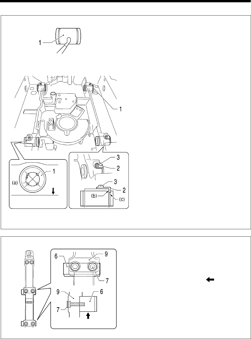
6. ASSEMBLY
RH-9820
105
A
1) Apply adhesive (Threebond 1373B) to the four
ball bearings (1).
2) Insert the four ball bearings (1) into the holes in
the bed so that the layout of the balls (a) is in
an "X" pattern on the base of the bed as shown
in the illustration.
3) While pushing the four ball bearing stoppers (2)
onto the base of the bed, tighten the four
screws (3).
* At this time, insert the projections (b) of the
four ball bearing stoppers (2) into the
grooves (c) and check that the ball bearing
stoppers (2) are flush with the bed surface.
B
Install the two gears (6) to X feed shaft holder N
(9) so that the gear (6) with the shorter distance
between the thread hole and the edge is on the
right.
* While pushing the two gears (6) in the
direction of the arrow at this time,
tighten the four socket bolts (7).
1004B
1005B
(Viewed from directly to
the left)
(Viewed from the side)
1108B
Base of
bed
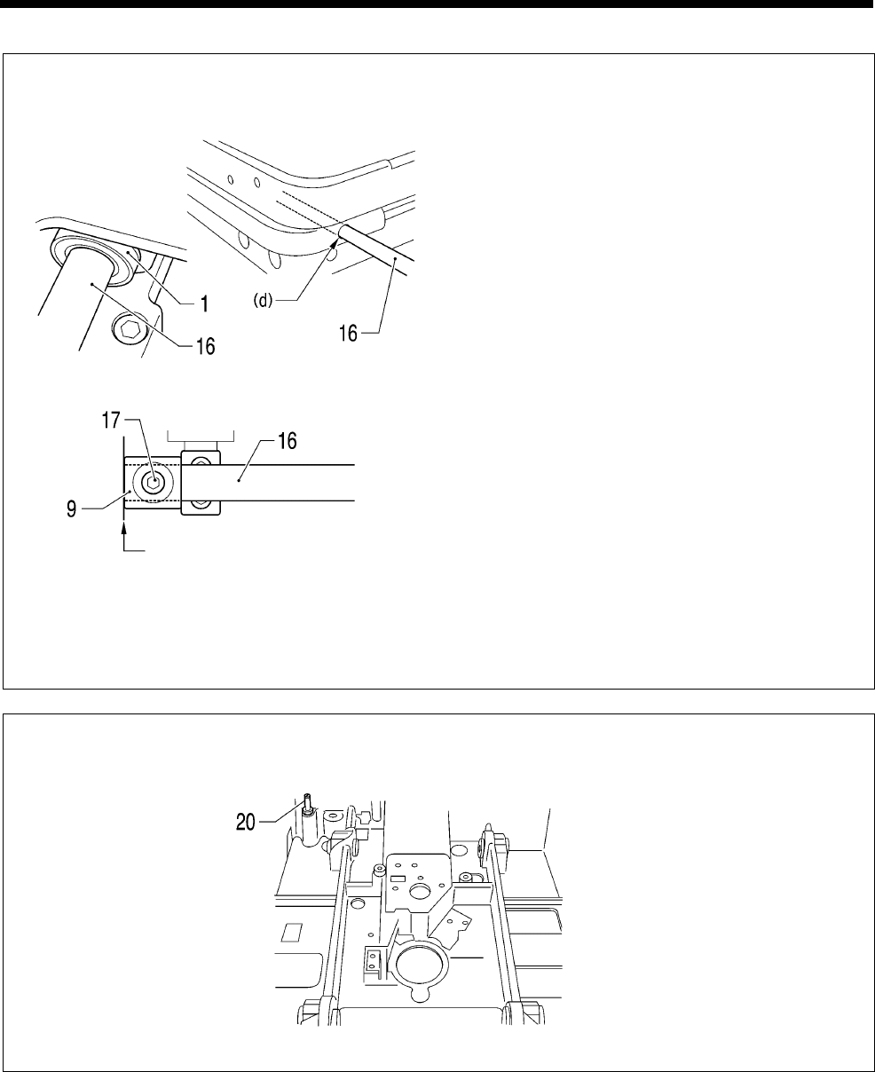
6. ASSEMBLY
RH-9820 106
C
1) Place the feed base unit onto the bed.
2) Insert the Y feed guide shaft (16) on the left
side into the hole (d) in the bed so that the end
with the screw stop goes in first, and pass it
through the two ball bearings (1).
3) Align the screw stop on the Y feed guide shaft
(16) with the screw hole in X feed shaft holder
N (9).
4) Align the end of the Y feed guide shaft (16) with
the end of X feed shaft holder N (9), and then
tighten the two set screws (17).
5) Install the Y feed guide shaft (16) on the right
side also by following steps 2 to 4 above.
D <For -01 specifications only>
Install the Cylinder screw (20) in the position shown in the illustration.
1006B
1007B
A
lign the edges.
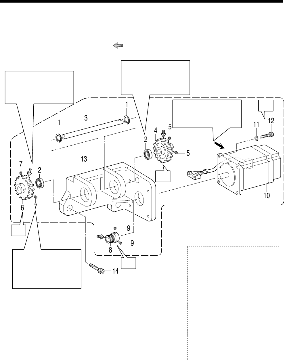
6. ASSEMBLY
RH-9820
107
6-16. X feed mechanism
* Refer to the detailed descriptions on the next page for details on A to C in the illustration.
* Apply the grease specified by Brother (Shin Lube EJ manufactured by Nippon Steel Chemical
Corporation) in the places indicated by .
1. Internal retaining rings [2 pcs]
2. Bearings [2 pcs]
3. X idler gear shaft
4. Idler gear
5. Set screws [2 pcs]
6. Idler gear
7. Set screws [2 pcs]
(Temporarily tighten)
8. Feed gear
9. Set screws [2 pcs]
10. Pulse motor X assembly
11. Plain washers [4 pcs]
12. Socket bolts [4 pcs]
13. X motor support
14. Socket bolts [3 pcs]
Install so that the motor
connectors are facing as
indicated by the arrow.
A
pply adhesive to the
outer circumferences of
the two bearings (2) and
then install.
0963B
A
pply adhesive to the
outer circumferences of
the two bearings (2) and
then install.
B
C
C
Install the X idler gear
shaft (3) so that there is
no play in the axial
direction and so that it
turns smoothly.
A
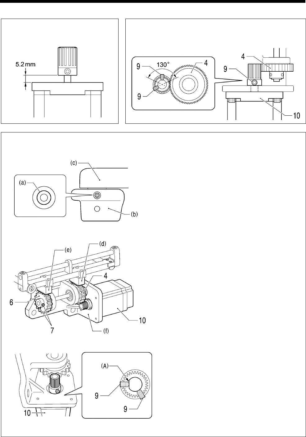
6. ASSEMBLY
RH-9820 108
A Assemble as shown in the
illustration.
B Place the pulse motor X assembly (10) against the idler
gear (4) so that the amount of play is 0.02 mm or less
within a range of 130° as shown in the illustration, and
then tighten the two set screws (9).
C Standard installation of motor unit (idler gear adjustment)
1) Place the feed base (c) onto the bed (b) so that
Y feed guide shaft (a) is positioned in the center
of the hole in the front of the bed (b).
2) Loosen the two set screws (7) of the idler gear
(6) in order to engage the X rack (e) and the
idler gear (6) while the X rack (d) and the idler
gear (4) are engaged in the standard position.
3) Set so that the screw stop (A) of the pulse
motor X assembly (10) and the two set screws
(9) of the feed gear (8) are in the positions
shown in the illustration.
4) While pushing the idler gear (4) and idler gear
(6) to engage them with the X racks (d) and (e)
at opposite sides, install the motor unit (f).
5) Tighten the two set screws (7) so that there is
no thrust play in the idler gear (6).
* If only removing the motor unit (f), steps 2 and
5 in the adjustment procedure for the idler gear
(6) can be omitted. (If carrying out any
disassembly or assembly which changes the
positions of the X racks or if re-adjusting the
backlash, carry out the full procedure.)
0964B
0966B
0967B
0968B
0965B
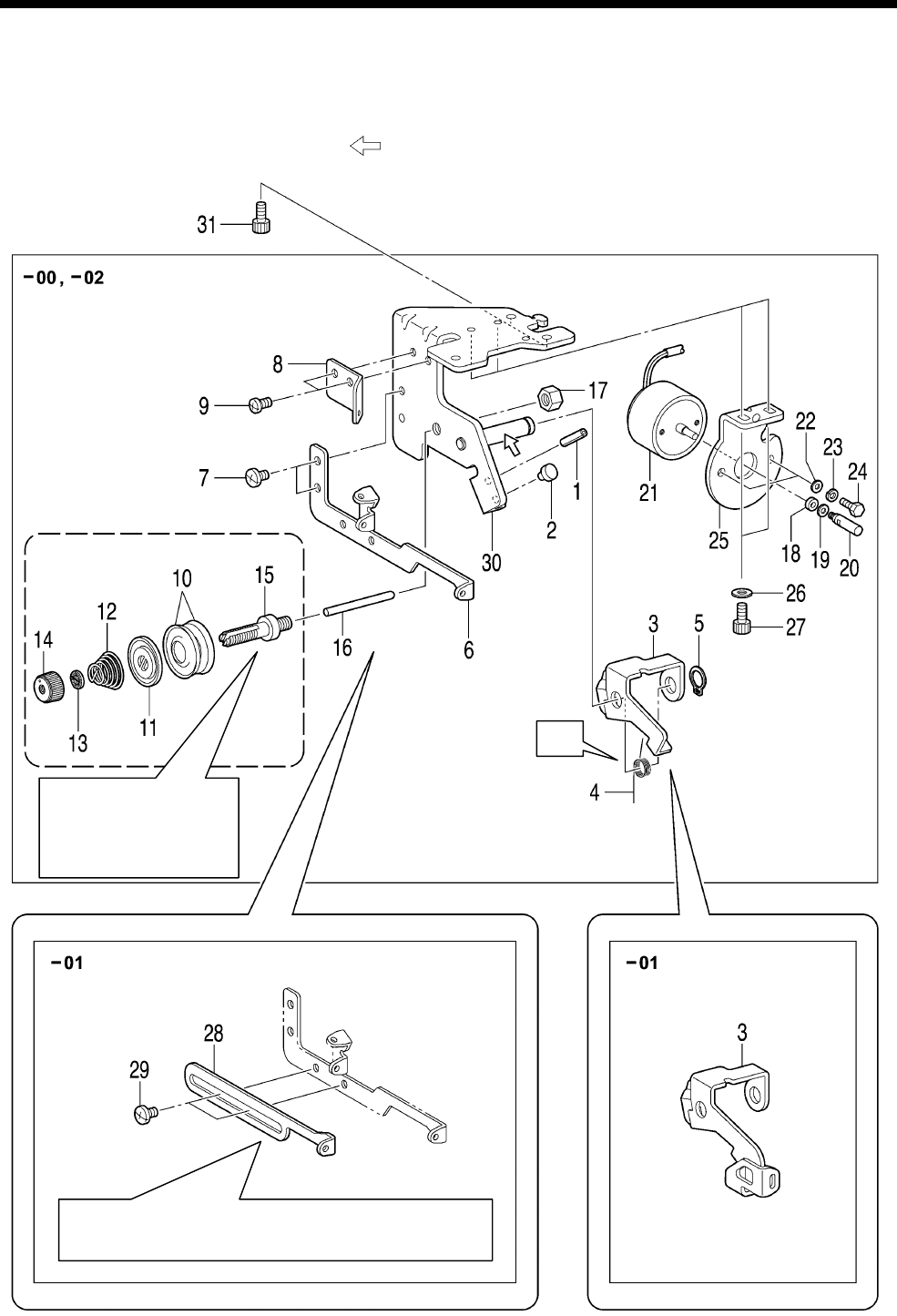
6. ASSEMBLY
RH-9820
109
6-17. Lower thread tension mechanism
* Refer to the detailed descriptions on the next page for details on A in the illustration.
* Apply the grease specified by Brother (MOLYKOTE LONGTERM W2 manufactured by Dow Corning
Corporation) in the places indicated by .
Refer to “7-32.
Adjusting the lower
thread loosening
amount”.
Refer to “7-23.
A
djusting the lower thread feeding
amount <-01 specifications only>”.
0969B
A
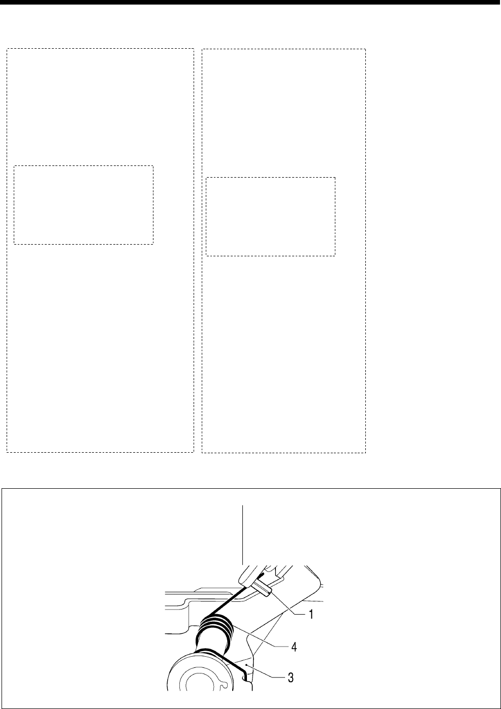
6. ASSEMBLY
RH-9820 110
[-00 and -02 specifications only]
1. Spring pin
2. Stopper
3. Lower thread release plate
4. Spring
5. Retaining ring C
6. Lower thread guide B
7. Screws [2 pcs]
8. Lower thread guide A
9. Screws [2 pcs]
10. Tension discs [2 pcs]
11. Tension disc presser
12. Spring
13. Washer
14. Tension nut
15. Tension stud
16. Tension release pin
17. Nut (Temporarily tighten)
18. Solenoid cushion
19. Washer
20. Solenoid shaft
21. Solenoid
22. Plain washers [2 pcs]
23. Spring washers [2 pcs]
24. Bolts [2 pcs]
25. Solenoid setting plate
26. Plain washers [2 pcs]
27. Socket bolts [2 pcs]
28. (Not used for -00 and -02
specifications)
29. (Not used for -00 and -02
specifications)
30. Lower thread guide adjusting plate
31. Socket bolts [3 pcs]
[-01 specifications only]
1. Spring pin
2. Stopper
3. Lower thread take-up guide
lever
4. Spring
5. Retaining ring C
6. Lower thread guide B
7. Screws [2 pcs]
8. Lower thread guide A
9. Screws [2 pcs]
10. Tension discs [2 pcs]
11. Tension disc presser
12. Spring
13. Washer
14. Tension nut
15. Tension stud
16. Tension release pin
17. Nut (Temporarily tighten)
18. Solenoid cushion
19. Washer
20. Solenoid shaft
21. Solenoid
22. Plain washers [2 pcs]
23. Spring washers [2 pcs]
24. Bolts [2 pcs]
25. Solenoid setting plate
26. Plain washers [2 pcs]
27. Socket bolts [2 pcs]
28. Lower thread guide C
29. Screws [2 pcs]
30. Lower thread guide adjusting
plate
31. Socket bolts [3 pcs]
A
[For -00 and -02 specifications]
Insert the longer end of the spring (4) into the
spring pin (1), and insert the shorter end into the
notch in the lower thread release plate (3).
[-01 specifications]
Insert the longer end of the spring (4) into the spring
pin (1), and insert the shorter end into the notch in the
lower thread take-up guide lever (3).
0970B
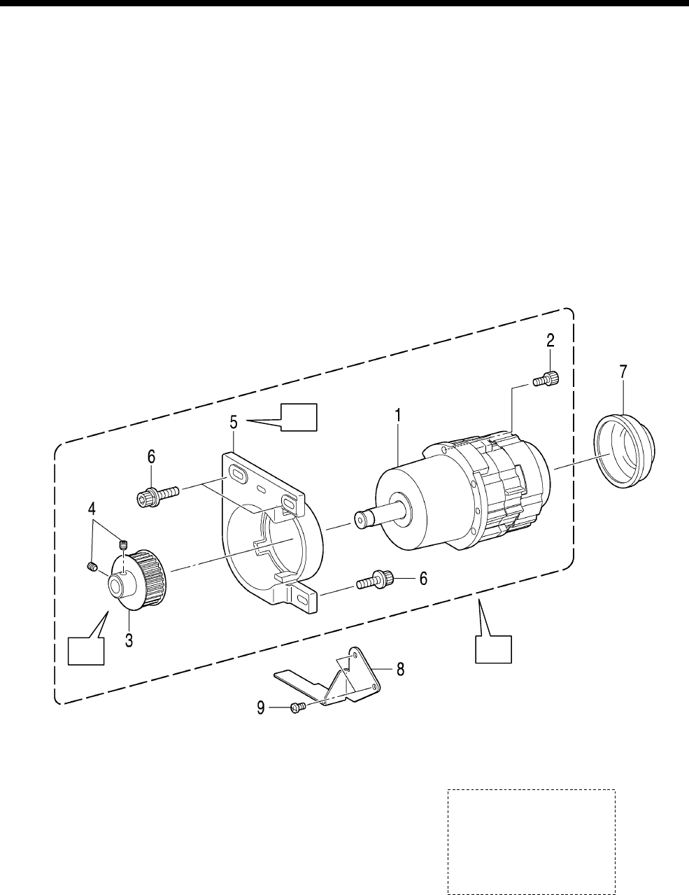
6. ASSEMBLY
RH-9820
111
6-18. Upper shaft motor mechanism
* Refer to the detailed descriptions on pages 112 to 114 for details on A to C in the illustration.
NOTE:
・ Check that the Y feed motor assembly and the pulse motor R assembly are installed before carrying out
this procedure.
If they are not installed, install them first.
・ After carrying out the procedure in “C Standard installation of upper shaft motor unit and belt tension
adjustment”, be sure to carry out the adjustments in “7-35. Adjusting the needle up signal home position for
the upper shaft and upper shaft motor” and “7-36. Adjusting the upper shaft stop position”.
1. Motor assembly
2. Socket bolts [5 pcs]
3. Timing pulley
4. Set screws [2 pcs]
5. Motor holder
6. Socket bolts with washers [3 pcs]
7. Motor cover
8. Belt guide
9. Screws [2 pcs]
A
B
C
0852B
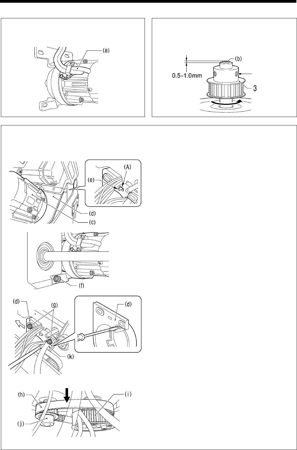
6. ASSEMBLY
RH-9820 112
A Install so that the cord (a) is in the position
shown in the illustration.
B Align the screw at the front of the timing pulley
(3) in the direction of rotation with the screw
stop on the motor shaft (b), and then tighten
the screw so that the shaft projects by 0.5 - 1.0
mm.
Screw stop
side
C Standard installation of upper shaft motor unit and belt tension adjustment
<If the belt (upper shaft - lower shaft) is not installed>
1) With the machine head tilted back, hold the
upper shaft motor unit (c) at the front, and place
the positioning pin (e) at the rear of the
machine head into the slot (A) in the motor
holder (d).
2) Provisionally screw in the socket bolt with
washer (f) until it is almost fully tightened.
3) Return the machine head to its original position.
4) Provisionally screw in the two remaining socket
bolts with washers (g) at the back of the
machine head until they are almost fully
tightened, and then place the motor on the
lower shaft side.
5) Place the belt (h) onto the lower shaft timing
pulley (i) and the motor pulley (j).
6) Insert a screwdriver into the gap between the
motor holder (d) and the bed (k) and move the
upper shaft motor unit (c) to the left to adjust
the tension of the belt (h) to within the range
given below.
• When using a new belt: 130 - 140 N
• When reusing an old belt: 90 - 100 N
7) Tighten the two socket bolts with washers (g).
8) Tilt back the machine head and fully tighten the
socket bolt with washer (f) at the front.
* Be sure to use a belt tension gauge to measure
the belt tension, and measure at the position
shown in the illustration.
* The belt tension gauge should be set to
measure a unit weight of 0.04 kg/m, a belt width
of 15 mm and a span length of 92 mm.
0855B
0853B 0854B
Measurement position
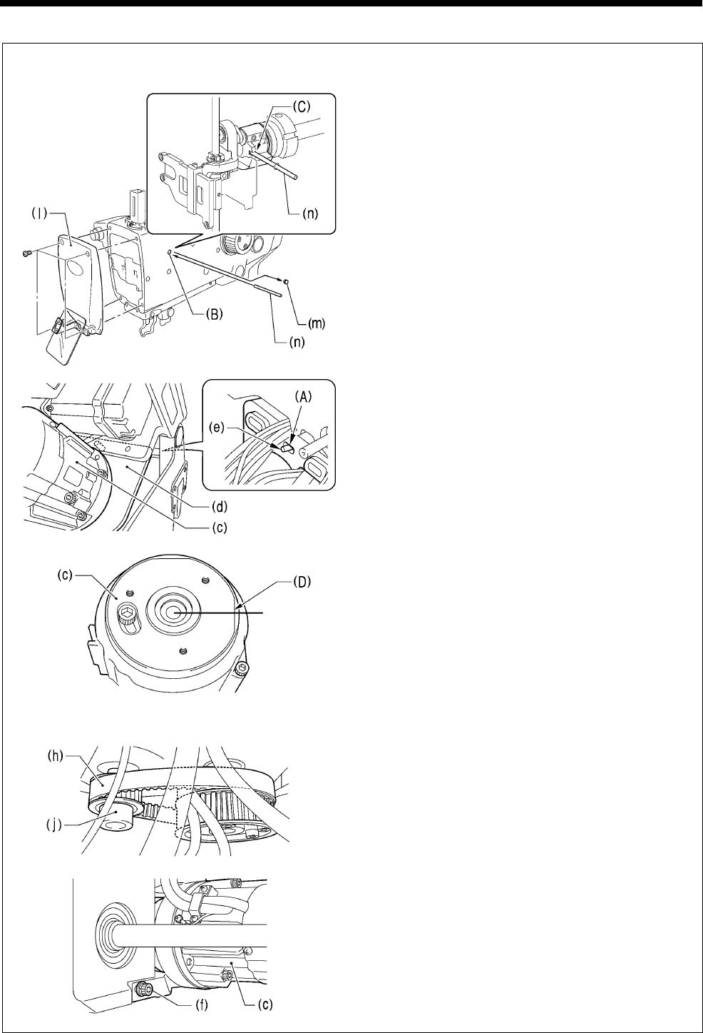
6. ASSEMBLY
RH-9820
113
<If the belt (upper shaft - lower shaft) is installed>
1) Remove the face plate (l) and the rubber cap
(m), and then insert the accessory pin (n) into
the groove (C) in the upper shaft crank from the
hole (B) in the arm to stop the upper shaft from
turning. (Upper shaft 0° position)
2) Remove the motor cover (7) if it is installed to
the upper shaft motor unit (c).
3) With the machine head tilted back, hold the
upper shaft motor unit (c) at the front, and then
place the belt (h) onto the motor pulley (j) so
that the D cut section (D) of the encoder is
facing directly to the right.
4) Place the positioning pin (e) at the rear of the
machine head into the slot (A) in the motor
holder (d).
5) Provisionally screw in the socket bolt with
washer (f) until it is almost fully tightened.
6) Return the machine head to its original position.
(Continued on next page)
0975B
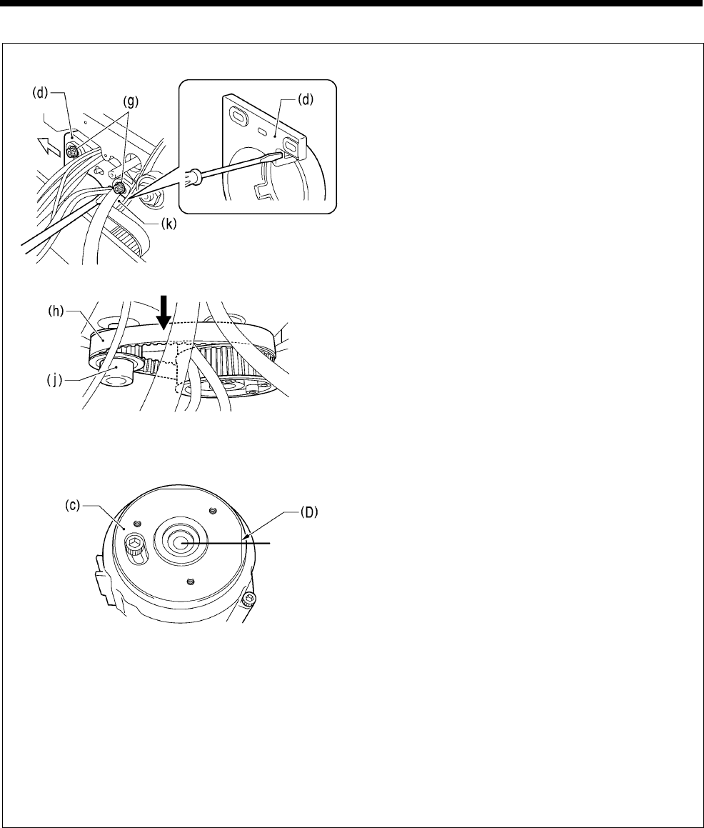
6. ASSEMBLY
RH-9820 114
7) Provisionally screw in the two remaining socket
bolts with washers (g) at the back of the
machine head until they are almost fully
tightened, and then place the motor on the
lower shaft side.
8) Insert a screwdriver into the gap between the
motor holder (d) and the bed (k) and move the
upper shaft motor unit (c) to the left to adjust
the tension of the belt (h) to within the range
given below.
• When using a new belt: 130 - 140 N
• When reusing an old belt: 90 - 100 N
* Be sure to use a belt tension gauge to measure
the belt tension, and measure at the position
shown in the illustration.
* The belt tension gauge should be set to
measure a unit weight of 0.04 kg/m, a belt width
of 15 mm and a span length of 92 mm.
9) Tighten the two socket bolts with washer (g).
10) Tilt back the machine head and fully tighten the
socket bolt with washer (f) at the front.
11) Check that the D cut section (D) of the encoder
is facing directly to the right ± 10° at this
time.
* If it is not in this position, repeat steps 3 to
10. (If it is not in the correct position, the
adjustment in “7-35. Adjusting the needle up
signal home position for the upper shaft and
upper shaft motor” will not be possible.)
NOTE:
If you do not have a belt tension gauge, adjust
so that the amount of deflection is
approximately 1 mm when a pressure of 5 N is
applied to the middle of the span (the
measurement position shown in the illustration).
0856B
Measurement position
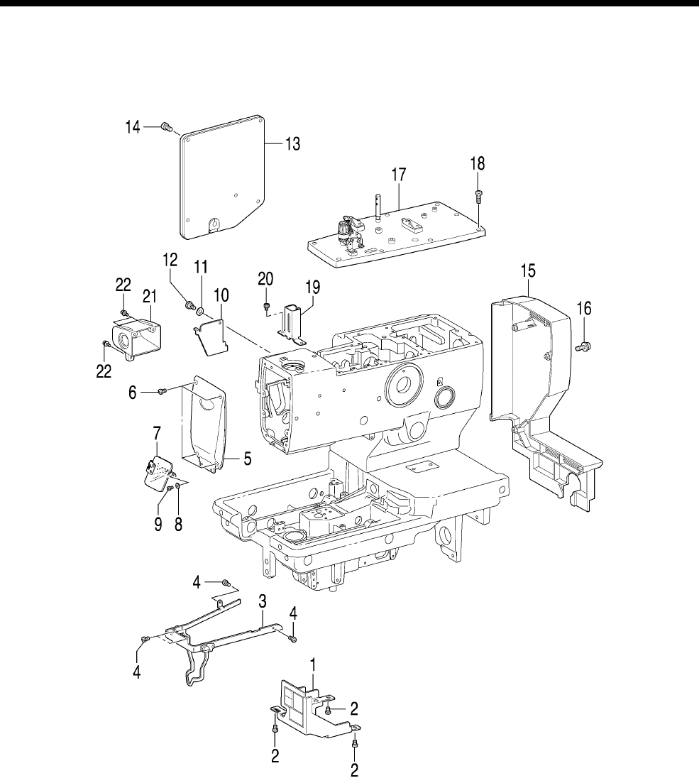
6. ASSEMBLY
RH-9820
115
6-19. Covers
1064B

6. ASSEMBLY
RH-9820 116
1. Cam cover
2. Screws [3 pcs]
3. Needle guide cover
4. Screws [4 pcs]
5. Main plate
6. Screws [4 pcs]
7. Eye guard assembly
8. Plain washers [2 pcs]
9. Screws [2 pcs]
10. Zigzag window cover
11. Wave washer
12. Shoulder screw
13. Rear cover
14. Screws [5 pcs]
15. Belt cover
16. Screws with washers [4 pcs]
17. Top cover assembly
18. Screws [9 pcs]
19. Needle bar guard
20. Socket bolts [2 pcs]
21. Switch cover
22. Screws with washers [3 pcs]
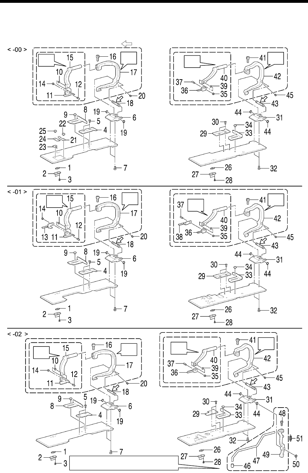
6. ASSEMBLY
RH-9820
117
6-20. Work clamp plate mechanism
* Refer to the detailed descriptions on pages 119 and 120 for details on A to D in the illustration.
* Apply the grease specified by Brother (MOLYKOTE LONGTERM W2 manufactured by Dow Corning
Corporation) in the places indicated by .
Refer to “7-26-4. Adjusting the position of the
sub clamp”.
1008B
B
A
DC
A
B DC
A
B DC

6. ASSEMBLY
RH-9820 118
1. Opening slide block
2. Slide block support plate
3. Screws [2 pcs]
4. Needle plate L
5. Flat screws [2 pcs]
6. Clamp shaft holder
7. Screws [2 pcs]
8. Cloth guide L
9. Screw
10. Bending washer
11. Work clamp L
12. Clamp support pin
13. Work clamp plate L
<-01 specifications only>
14. Nut
15. Clamp arm L
16. Socket bolt (Temporarily tighten)
17. Clamp lever L
18. Clamp fulcrum shaft
19. Retaining rings C [2 pcs]
20. Set screws [2 pcs]
21. Plate spring
22. Screw
23. Thread trimmer B
24. Thread trimmer A
25. Screw
26. Opening slide block
27. Slide block support plate
28. Screws [2 pcs]
29. Needle plate R
30. Flat screws [2 pcs]
31. Clamp shaft holder
32. Screws [2 pcs]
33. Cloth guide R
34. Screw
35. Bending washer
36. Cloth work clamp R
37. Clamp support pin
38. Work clamp plate R
<-01 specifications only>
39. Nut
40. Clamp arm R
41. Socket bolt (Temporarily tighten)
42. Clamp lever R
43. Clamp fulcrum shaft
44. Retaining rings C [2 pcs]
45. Set screws [2 pcs]
46. Cloth work clamp A
47. Sub auxiliary clamp wrist
48. Socket bolt (Temporarily tighten)
49. Auxiliary clamp arm
50. Retaining rings C
51. Spring
<-00 specifications only>
<-02 specifications only>
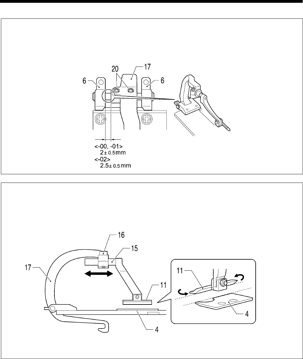
6. ASSEMBLY
RH-9820
119
A Cloth work clamp L sideways position adjustment
1) Set so that the clearance between the clamp shaft holder (6) and clamp lever L (17) is at the distance
shown in the illustration.
2) After adjusting, tighten the two set screws (20).
B Cloth work clamp L forward/back adjustment
1) Loosen the socket bolt (16) and then adjust the forward/back position of clamp arm L (15).
2) Next, adjust cloth work clamp L (11) so that its side is flush with the side of needle plate L (4).
3) Once adjustment is complete, tighten the socket bolt (16).
(Viewed from directly to the left)
1009B
1010B
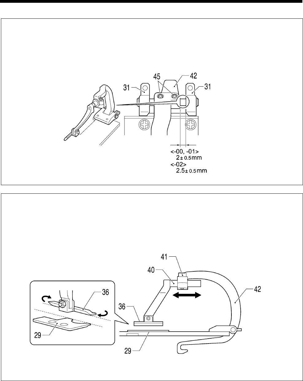
6. ASSEMBLY
RH-9820 120
C Cloth work clamp R sideways adjustment
1) Set so that the clearance between the clamp shaft holder (31) and clamp lever R (42) is at the distance
shown in the illustration.
2) After adjusting, tighten the two set screws (45).
D Cloth work clamp R forward/back adjustment
1) Loosen the socket bolt (41) and then adjust the forward/back position of clamp arm R (40).
2) Next, adjust the cloth work clamp R (36) so that its side is flush with the side of needle plate R (29).
3) Once adjustment is complete, tighten the socket bolt (41).
(Viewed from directly to the right)
1012B
1011B
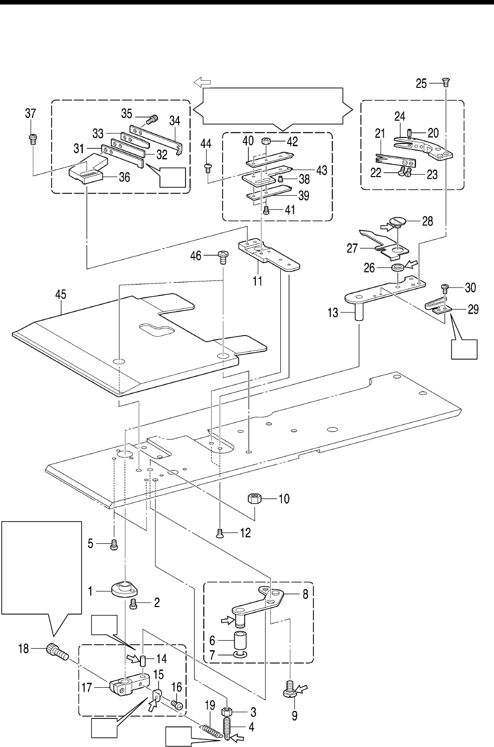
6. ASSEMBLY
RH-9820
121
6-21. Lower thread trimming mechanism
<-01 specifications>
* Refer to the detailed descriptions on pages 123 and 124 for details on A to E in the illustration.
* Apply the grease specified by Brother (MOLYKOTE LONGTERM W2 manufactured by Dow Corning
Corporation) in the places indicated by .
1013B
A
C
B
D
Refer to “7-25. Replacing and
adjusting the movable knife and fixed
knife (for the lower thread and gimp)
<-01 specifications>”.
Refer to “7-25.
Replacing and
adjusting the
movable knife and
fixed knife (for the
lower thread and
gimp) <-01
specifications>”.
E

6. ASSEMBLY
RH-9820 122
1. Bush thread trimmer arm
2. Screws [2 pcs]
3. Nut
4. Spring hook
5. Screws [2 pcs]
6. Roller
7. Retaining ring
8. Thread trimmer link lever
assembly
9. Shoulder screw
10. Nut
11. Fixed knife bracket
12. Flat screws [2 pcs]
13. Thread trimmer arm
14. Pin
15. Spring hook
16. Screw
17. Thread cutter lever arm
18. Socket bolt
(Temporarily tighten)
19. Spring
20. Pin
21. Thread handler
22. Flat screw
(Temporarily tighten)
23. Screw
(Temporarily tighten)
24. Movable knife
25. Flat screws [3 pcs]
26. Movable knife collar
27. Thread nipper opener
28. Shoulder screw
29. Opener spring
30. Screws [2 pcs]
31. Fixed knife
32. Fixed knife plate spring
33. Fixed knife plate spring U
34. Thread guide plate
35. Socket bolts [2 pcs]
36. Fixed knife setting bracket
37. Screws [2 pcs]
(Temporarily tighten)
38. Opener pin
39. Thread nipper D
40. Thread nipper U
41. Screws [2 pcs]
42. Nuts [2 pcs]
43. Thread nipper M
44. Screws [2 pcs]
(Temporarily tighten)
45. Work clamp plate U
46. Screws [2 pcs]
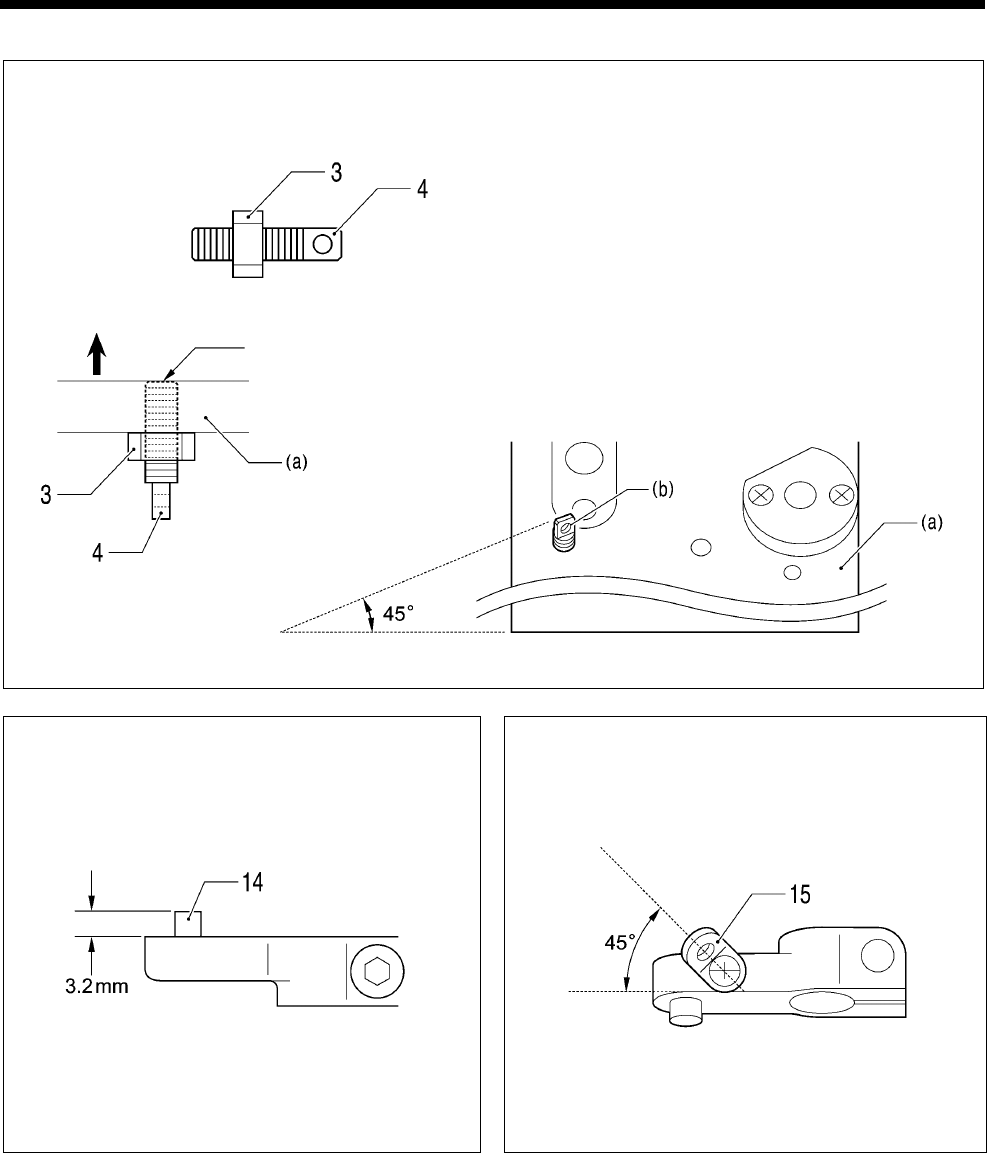
6. ASSEMBLY
RH-9820
123
A Spring hook installation
1) Provisionally tighten the nut (3) about halfway
onto the spring hook (4).
2) Install the spring hook (4) to the cloth work
clamp plate (a), and then tighten the nut (3)
until the end of the spring hook (4) is flush with
the top surface of the cloth work clamp plate
(a).
* Install the spring hook (4) so that the hole
(b) is facing in the direction shown in the
illustration.
B Install the pin (14) so that it projects by the
distance shown in the illustration.
C Install the spring hook (15) so that it faces in
the direction shown in the illustration.
1014B
1015B 1016B
(Top)
(Bottom)
Should be flush
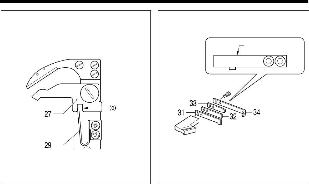
6. ASSEMBLY
RH-9820 124
D Insert the end of the opener spring (29) into
the notch (c) of the thread nipper opener (27).
E Install all parts so that the edges are aligned as
shown in the illustration.
1017B 1018B
A
lign the edges.
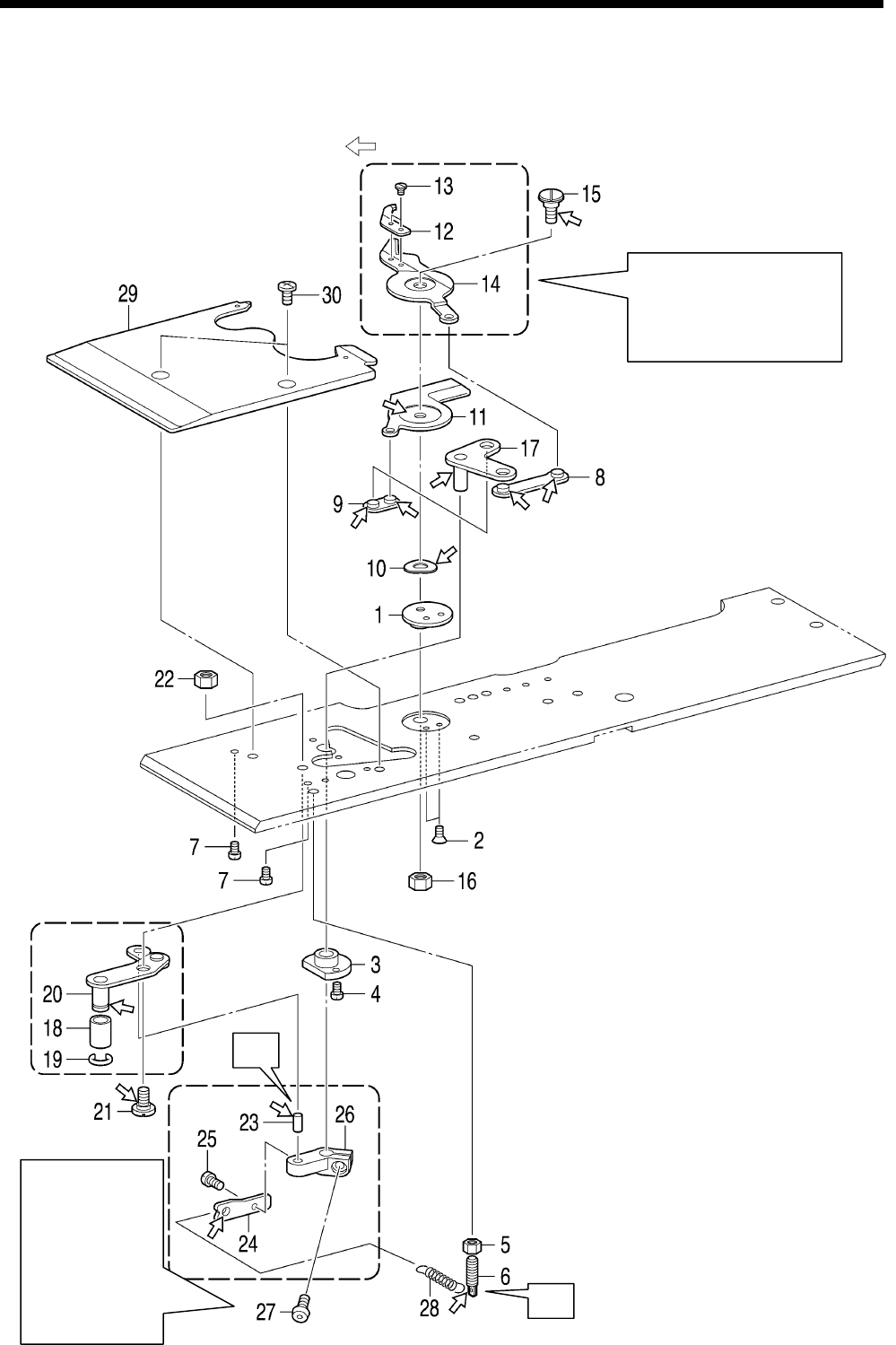
6. ASSEMBLY
RH-9820
125
<-02 specifications>
* Refer to the detailed descriptions on the next page for details on F and G in the illustration.
* Apply the grease specified by Brother (MOLYKOTE LONGTERM W2 manufactured by Dow Corning
Corporation) in the places indicated by .
1019B
F
G
Refer to “7-26.
Replacing and
adjusting the
movable knife
and fixed knife
(for the lower
thread and gimp)
<-02
specifications>”.
Refer to “7-26. Replacing
and adjusting the movable
knife and fixed knife (for the
lower thread and gimp) <-02
specifications>”.
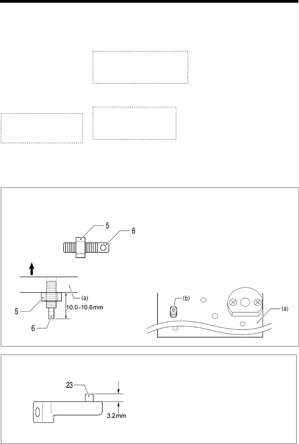
6. ASSEMBLY
RH-9820 126
1. Knife support washer
2. Flat screws [2 pcs]
3. Bush thread trimmer arm
4. Screws [2 pcs]
5. Nut
6. Spring hook
7. Screws [2 pcs]
8. Thread trimmer link A
assembly
9. Thread trimmer link B
assembly
10. Wave washer
11. Movable knife R
12. Thread handler
13. Screws [2 pcs]
14. Movable knife L
15. Shoulder screw
(Temporarily tighten)
16. Nut (Temporarily tighten)
17. Movable knife driving plate
18. Roller
19. Retaining ring
20. Thread trimmer link lever J
assembly
21. Shoulder screw
22. Nut
23. Pin
24. Spring hook
25. Screw
26. Thread cutter lever arm
27. Socket bolt
(Temporarily tighten)
28. Spring
29. Work clamp plate JU
30. Screws [2 pcs]
F Spring hook installation
1) Provisionally tighten the nut (5) about halfway
onto the spring hook (6).
2) Install the spring hook (6) to the cloth work
clamp plate (a), and then tighten the nut (5) to
the position shown in the illustration.
* Check that the end of the spring hook (6) is
not protruding from the surface of the cloth
work clamp plate (a).
* Install the spring hook (6) so that the hole
(b) faces in the direction shown in the
illustration.
G
Install the pin (23) so that it projects by the
distance shown in the illustration.
1020B
1021B
(Top)
(Bottom)
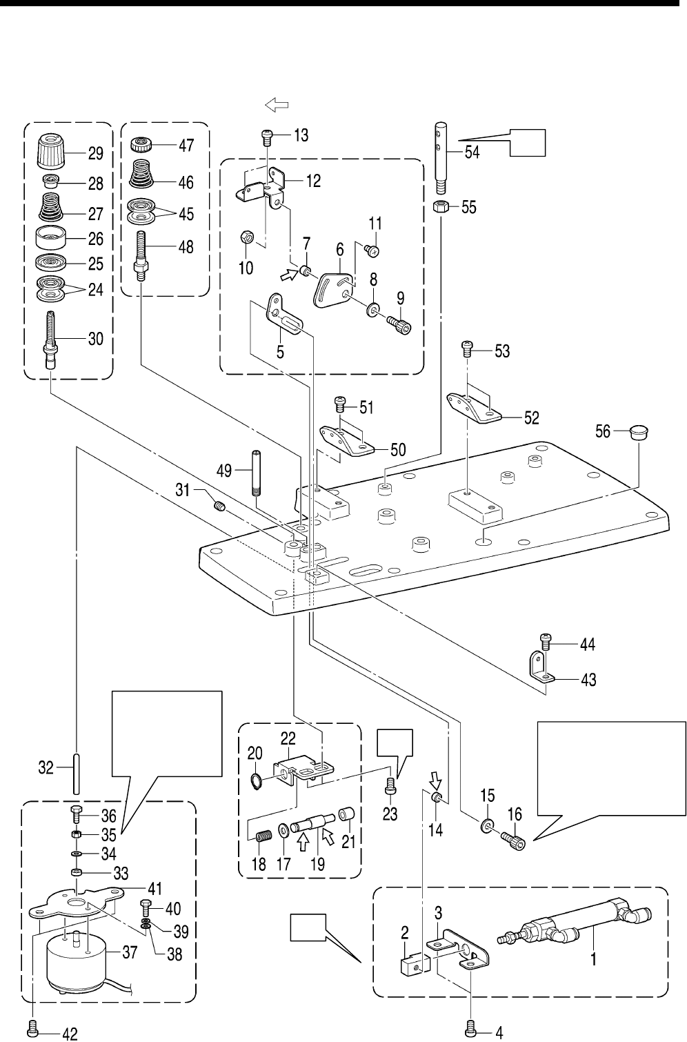
6. ASSEMBLY
RH-9820
127
6-22. Upper cover mechanism (upper thread tension release and upper
thread take-up mechanisms and upper thread path)
* Refer to the detailed descriptions on the next page for details on A to C in the illustration.
* Apply the grease specified by Brother (MOLYKOTE LONGTERM W2 manufactured by Dow Corning
Corporation) in the places indicated by .
Refer to “7-31.
A
djusting the
upper thread
loosening
amount”.
A
fter installing the
Socket bolt (16),
tighten the two screws
(4) so that the cylinder
moves smoothly.
0857B
A
C
B
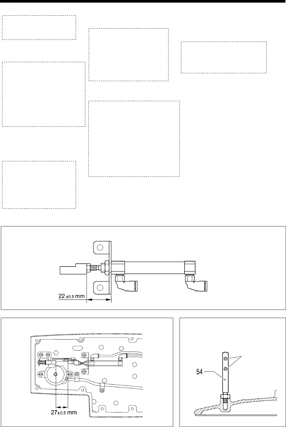
6. ASSEMBLY
RH-9820 128
1. Cylinder assembly
2. Cylinder joint A
3. Cylinder setting plate A
4. Screws [2 pcs]
(Temporarily tighten)
5. Thread take-up lever
driving plate
6. Thread take-up lever plate
7. Collar A
8. Washer
9. Socket bolt
10. Nut
11. Screw
12. Thread take-up lever base
13. Screws [2 pcs]
14. Collar B
15. Washer
16. Socket bolt
17. Plain washer
18. Compression spring
19. Impact support shaft
20. Retaining ring C
21. Button clamp A
22. Impact support plate
23. Screws [2 pcs]
24. Tension discs [2 pcs]
25. Tension disc presser
26. Tension disc presser
27. Tension spring
28. Washer
29. Tension nut
30. Tension stud U
31. Set screw
32. Tension release pin
33. Solenoid cushion
34. Washer
35. Nut
36. Bolt
37. Upper thread tension release
solenoid
38. Plain washers [2 pcs]
39. Spring washers [2 pcs]
40. Bolts [2 pcs]
41. Solenoid setting plate
42. Screws [2 pcs]
43. Upper thread guide A
44. Screw
45. Thread guide discs [2 pcs]
46. Pre-tension spring B
47. Tension nut
48. Tension stud
49. Thread guide rod A
50. Sewing thread retainer guide
51. Screws [2 pcs]
52. Sewing thread retainer guide
53. Screws [2 pcs]
54. Thread spool pin
55. Nut
56. Rubber cap
A Assemble as shown in the illustration.
B Assemble as shown in the illustration.
C Install the thread spool pin (54) so
that the holes face in the direction
shown in the illustration.
0858B
0860B
0859B
Holes
(When cylinder is at
maximum retraction)
(When cylinder is at maximum retraction)
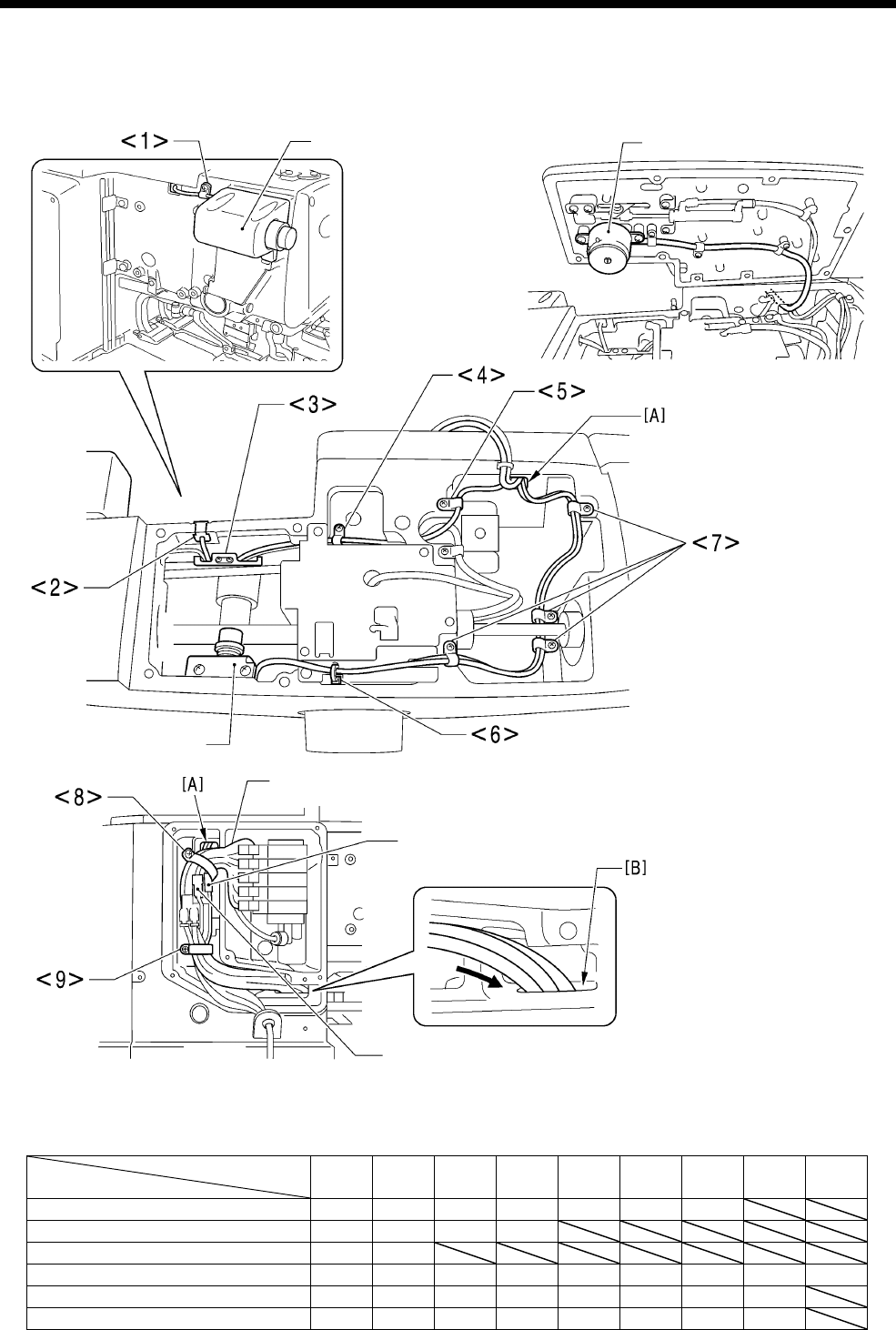
6. ASSEMBLY
RH-9820
129
6-23. Routing the harnesses
Route the harnesses from the various parts in the order shown in the table below.
<1> Cord holder
<2> Cord bush
<3> Cord holder
<4> Cord holder
<5> Cord holder
<6> Fastening band
<7> Cord holder
<8> Cord holder
<9> Cord holder
<10> Cord holder
<11> Cord holder
<12> Cord holder
<13> Cord holder
<14> Cord holder
[A]-[G]:Indicates holes
[H]:Indicates a gap
Routing order
Part name 1 2 3 4 5 6 7 8 9
Stop switch <1> <2> <3> <4> <5> [A] <8>
Cutter sensor <6> <7> [A] <8>
Upper tension release solenoid [A] <8>
Main valve harness <8> <9> [B] [E] <12> [F] <13> <14> [G]
Relay harness <9> [B] [E] <12> [F] <13> <14> [G]
Upper thread solenoid harness <9> [B] [E] <12> [F] <13> <14> [G]
1106B
Stop switch Upper tension release
solenoid
Cutter sensor
Main valve harness
Relay harness
Upper thread
solenoid harness
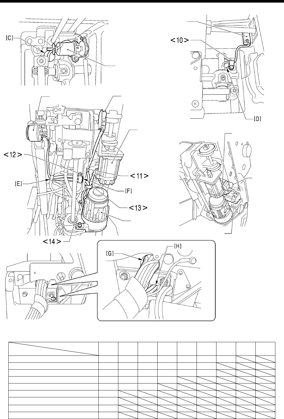
6. ASSEMBLY
RH-9820 130
Routing order
Part name 1 2 3 4 5 6 7 8 9
Gimp thread solenoid [C] [E] <12> [F] <13> <14> [G]
Y sensor <10> [D] <11> <13> <14> [G]
Lower tension release solenoid [E] <12> [F] <13> <14> [G]
Safety switch <11> <13> <14> [G]
X motor <13> <14> [G]
Y motor [G]
θmotor [G]
Upper shaft motor [H]
Fan [G]
1107B
Y sensor
Gimp thread solenoid
Safety switch
Lower tension release
solenoid
X motor θ motor
Fan
Y motor
Upper shaft motor
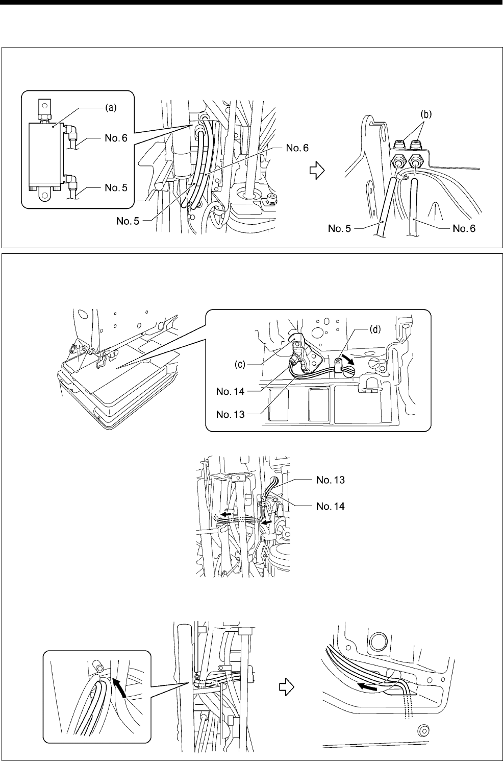
6. ASSEMBLY
RH-9820
131
6-24. Routing the air tubes
Cutter cylinder
Insert the air tubes (No. 5 and No. 6) of the cutter cylinder (a) into the elbows (b) in the bed base.
* Insert the air tubes into the elbows (b) with the same numbers.
Upper thread cutter cylinder
1) Pass the air tubes (No. 13 and No. 14) of the upper thread cutter cylinder (c) through the hole in the bed
and out through the bottom.
2) Secure the air tubes with the cord holder (d).
3) Pass the air tubes (No. 13 and No. 14) through the hole in the bed as shown in the illustration below.
4) Pass the air tubes (No. 13 and No. 14) out through the bottom of the bed into the side of the arm, and
then pass them out through the side of the arm.
1066B
1067B
1068B
1065B
(Left side of arm)
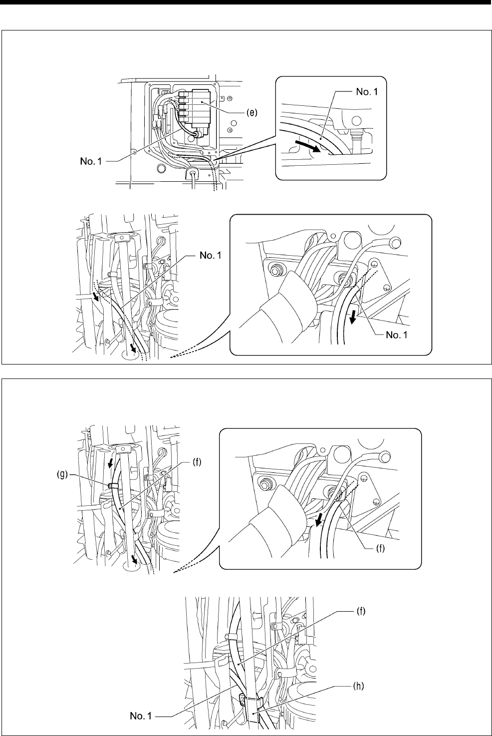
6. ASSEMBLY
RH-9820 132
Valve unit
1) Pass the air tube (No. 1) of the valve unit (e) from the side marked with “1” into the hole in the side of the
arm and out into the bottom of the bed.
2) Pass the air tube (No. 1) through the hole in the bed and out from the rear of the bed.
Cutting scraps
1) Secure the air tube (f) for cutting scraps with the cord holder (g).
2) Pass the air tube (f) for cutting scraps through the hole and out from the rear of the bed.
3) Secure the air tube (No. 1) for the valve unit (e) and the air tube (f) for cutting scraps with the tube
presser (h).
1069B
1070B
1071B
1072B
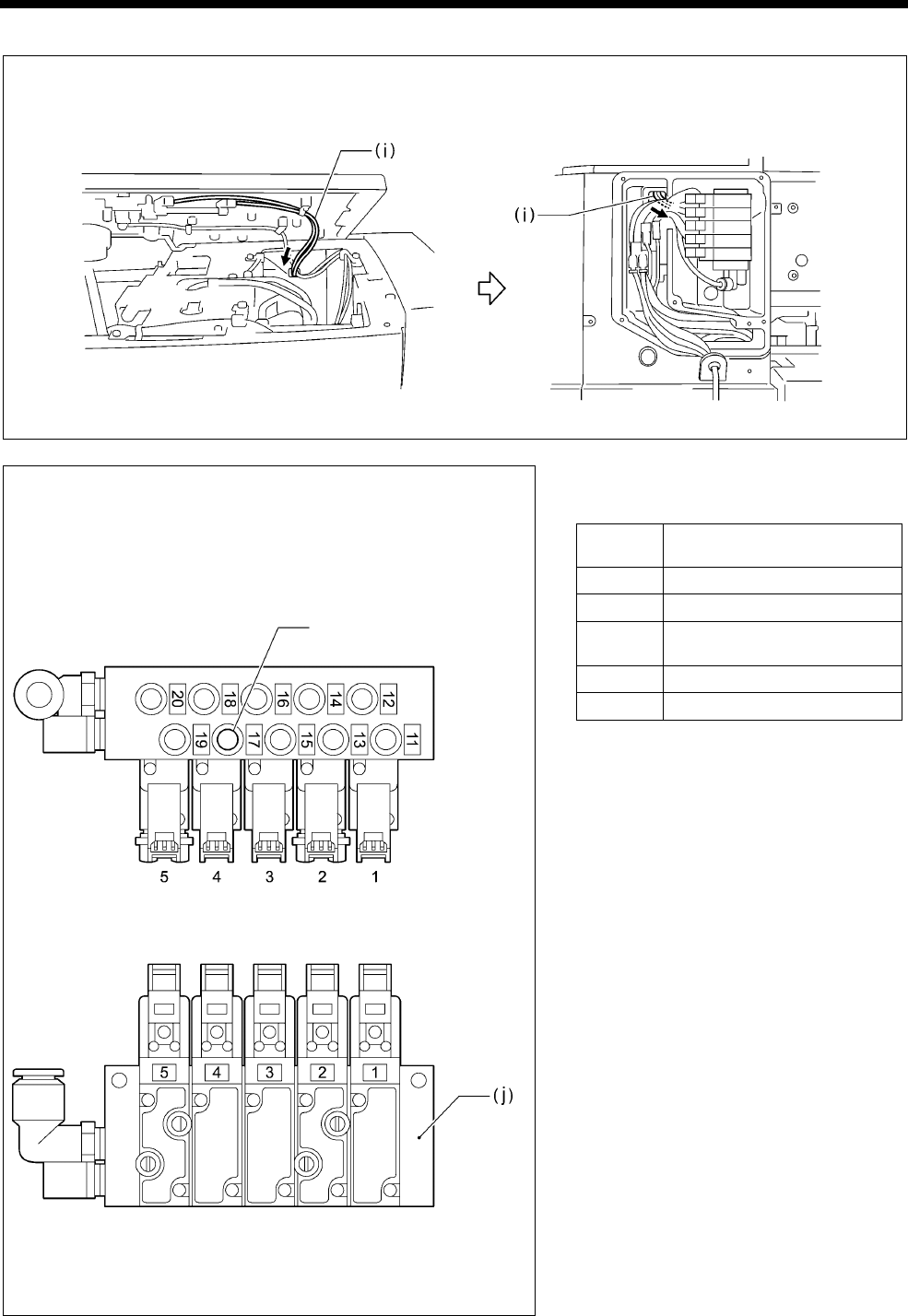
6. ASSEMBLY
RH-9820
133
Upper tension release cylinder
Pass the air tube (i) for the upper tension release cylinder through the hole in the arm and out from the side
of the rear cover.
Connecting the air tubes
Insert the air tubes onto the nipples of the solenoid valve
assembly (j).
* There are numbers marked on each air tube. Insert the air
tubes onto nipples with corresponding numbers.
《Solenoid valve tubes and functions》
Label
No. Solenoid valve type
1 For upper thread take-up
2 For upper thread trimming
3 For cloth spreading (+ for
auxiliary clamp arm *1)
4 For cloth work clamp
5 For lower thread trimming *2
*1: Auxiliary clamp arm is for -02 specifications
only.
*2: The solenoid valve for label No. 5 is not
present in specifications without a lower
thread trimmer.
1073B
(Left side of arm)
1074B
Insert the plug (4).
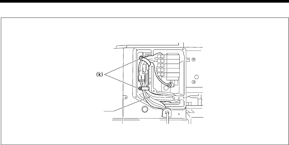
6. ASSEMBLY
RH-9820 134
Securing the air tubes
Secure the air tubes and the harnesses with the cord holders (k) (2 places).
Tubes and harnesses from the feed base
1075B
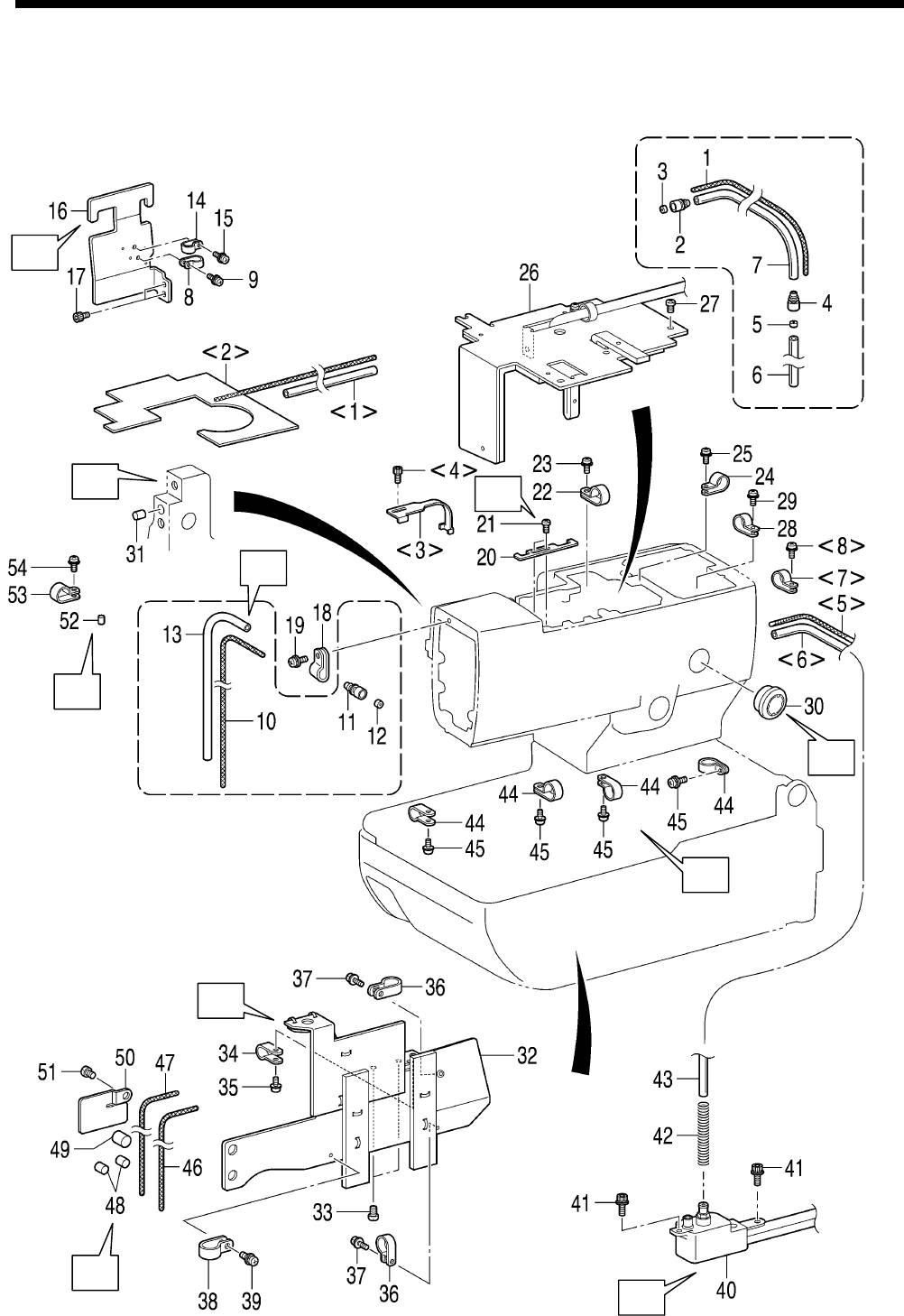
6. ASSEMBLY
RH-9820
135
6-25. Lubrication and greasing and routing the oil tubes
* <1> to <8> should be done before carrying out the assembly procedure in “6-1. Cutter mechanism”.
* Refer to the detailed descriptions on pages 136 to 140 for details on A to J in the illustration.
1029B
A
E C
B
J
D
H
F
I
G
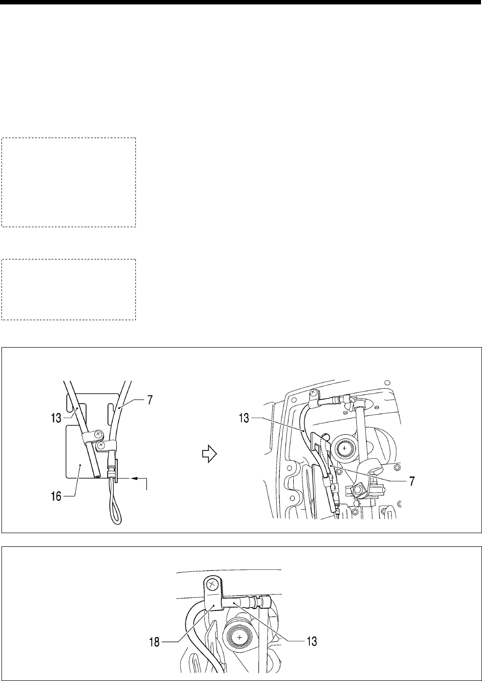
6. ASSEMBLY
RH-9820 136
<1> Oil tube
<2> Felt assembly
(Attach with glue)
<3> Tube guide
<4> Socket bolt
<5> Wick
<6> Oil tube
<7> Cord holder #5
<8> Screw
1. Wick
2. Oil tube
3. Oil joint S
4. Collar
5. Oil joint S
6. Collar
7. Oil tube
8. Cord holder (NK-3N)
9. Screw
10. Wick
11. Oil joint S
12. Collar
13. Oil tube
14. Cord holder (NK-3N)
15. Screw
16. Tube support
17. Socket bolts [2 pcs]
18. Cord holder (NK-3N)
19. Screw
20. Cord holder
21. Screws [2 pcs]
22. Cord holder
23. Screw
24. Cord holder (NK-3N)
25. Screw
26. Oil plate assembly
27. Screws [4 pcs]
28. Cord holder #5
29. Screw
30. Oil gauge window
31. Felt
32. Lower shaft cover assembly
33. Screws [2 pcs]
34. Cord holders #5
35. Screw
36. Cord holders #10 [2 pcs]
37. Screws [2 pcs]
38. Cord holder (NK-3N)
39. Screw
40. Sub-tank assembly
41. Socket bolts [2 pcs]
42. Tube clip spring
43. Oil tube (<6>)
(Push into sub-tank)
44. Cord holders (7N) [4 pcs]
45. Screws [4 pcs]
46. Wick
47. Wick
48. Felts [2 pcs]
49. Felt
50. Tube support B
51. Screw
52. Felt
53. Cord holder #5
54. Screw
A Install the oil tube (7) and the oil tube (13) to the tube support (16) as shown in the illustration.
B Secure the oil tube (13) with the cord holder (NK-3N) (18) as shown in the illustration.
1030B
1031B
A
lign the
edges
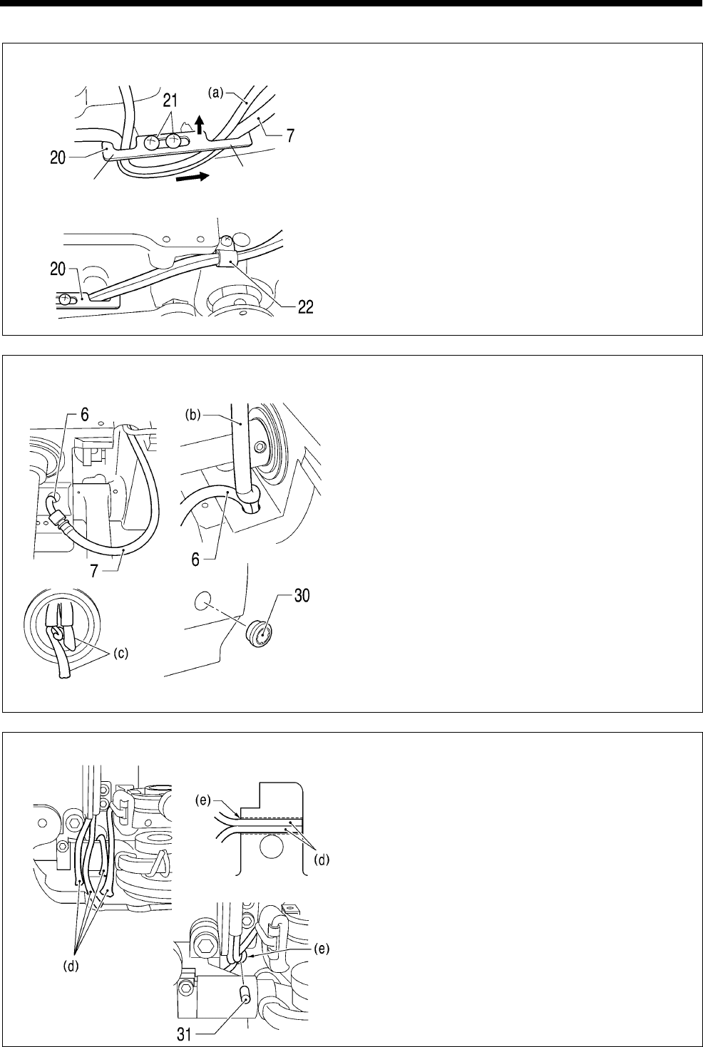
6. ASSEMBLY
RH-9820
137
C Cord holder (20) installation
1) Install the cord holder (20) so that the side with
the wider hook is on the right as shown in the
illustration, and then while gently pushing it in
the direction of the arrow, tighten the two
screws (21) to secure it in place.
2) Secure the oil tube (7) behind the cord presser
(20) and the stop switch cord (a) with the cord
presser (22).
D Tapping in the oil pot window
1) Insert the oil tube (6) and the oil tube (b)
coming from the oil plate assembly (26) into the
oil tank.
2) Check that the wick (c) is attached to the base
of the oil tank, and then tap in the oil gauge
window (30).
E Inserting the wicks
1) Insert the four wicks (d) into the arm relay hole
(e).
* Insert the four wicks (d) securely into the
holes as far as they will go.
* A list of the four wicks (d) is as follows.
・Wick (1)
・Wick (10)
・Felt presser assembly (7) in “6-6. Needle
bar mechanism (2)”
・Wick (11) in “6-3. Zigzag mechanism”
2) Push in the felt (31).
1032B
1033B
1034B
Narrow
side
Wide
side
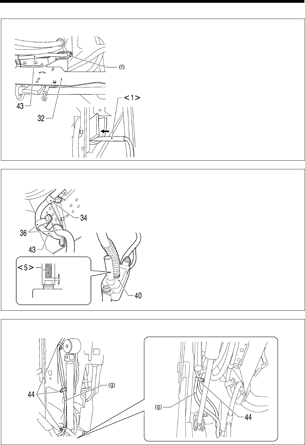
6. ASSEMBLY
RH-9820 138
F Installing the lower shaft cover assembly
1) Pass the oil tube (43) through the hole (f) in the
lower shaft cover assembly (32).
2) Pass the oil tube <1> from the arm through the
felts.
G
1) Secure the oil tube (43) with the cord holder #5
(34).
2) Install the two cord holders #10 (36) as guides
for routing the oil tube (43).
3) Connect the oil tube (43) to the sub-tank
assembly (40).
* Make sure that the wick <5> does not cover
the hole.
H Secure the oil tube (g) coming from the sub tank assembly (40) with the four cord holders (44).
1035B
1036B
1037B
Maintain a
clearance
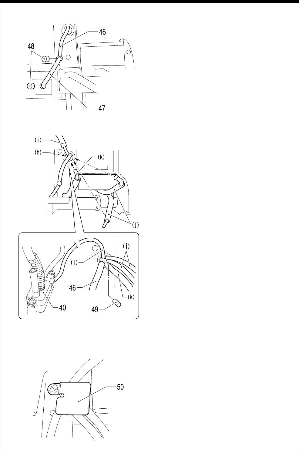
6. ASSEMBLY
RH-9820
139
I
1) Insert the wicks (46) and (47) into the hole in
the bed as far as they will go.
2) Push the two felts (48) into the positions shown
in the illustration.
3) Insert the four wicks mentioned below into the
bed hole (h).
・ Thin wick (i) coming from sub tank assembly
(40)
・ Wick (6) and wick (8) (j) of “6-11. Looper
mechanism”
・ Wick (4) (k) of “6-12. Spreader mechanism”
4) Push the felt (49) into the bed hole (h).
5) Secure the oil tubes with the tube support B
(50).
1038B
1039B
1040B
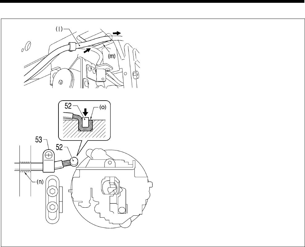
6. ASSEMBLY
RH-9820 140
J
1) Pass the thicker oil tube (l) through the
underside of the bed.
2) Pass the oil tube (l) through the hole (m), (n) in
the bed and out from the looper base side.
3) Push the felt (52) in through the hole (o) in the
bed so that it is touching the wick.
4) Secure the oil tube (l) with cord holder #5 (53).
1041B
1042B
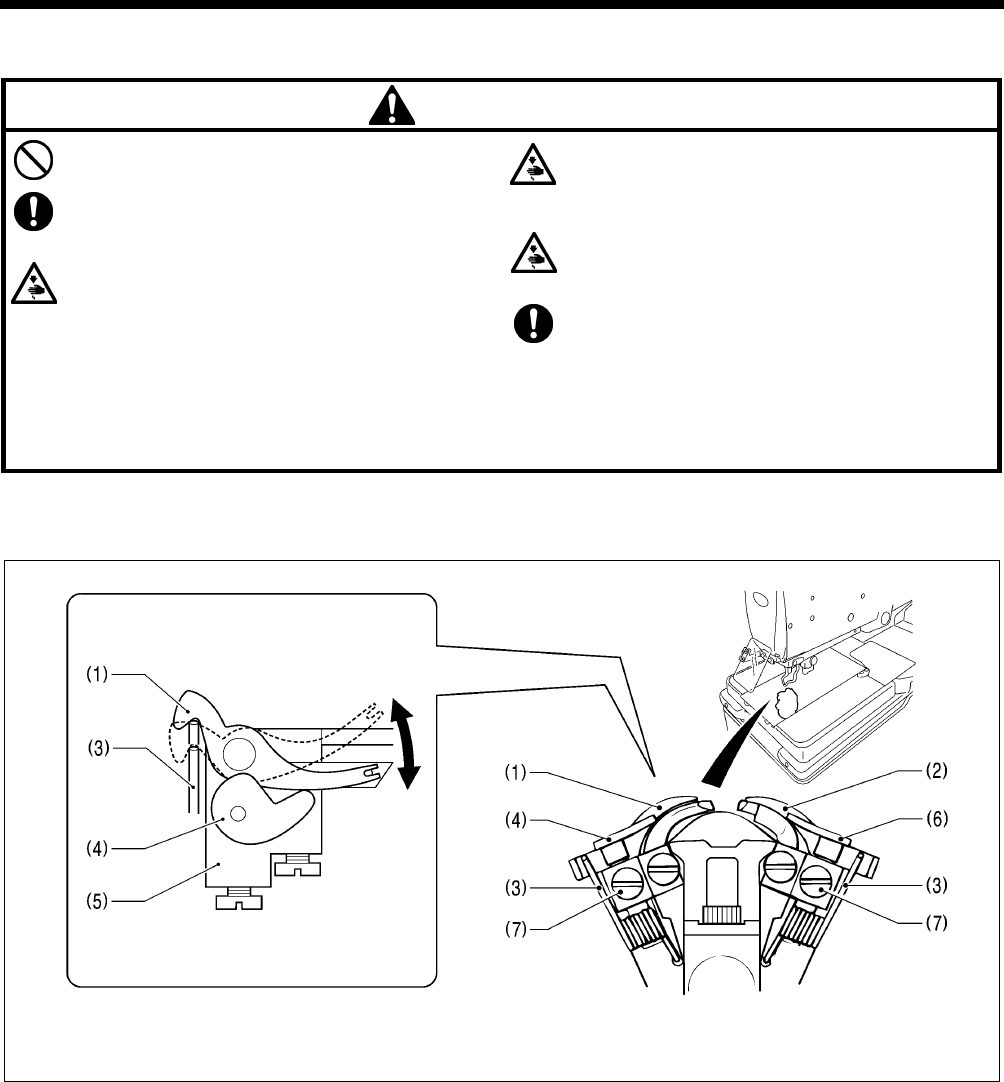
7. ADJUSTMENTS
RH-9820
141
7. ADJUSTMENTS
CAUTION
Maintenance and inspection of the sewing machine
should only be carried out by a qualified technician.
Ask your Brother dealer or a qualified electrician to
carry out any maintenance and inspection of the
electrical system.
Turn off the power switch and disconnect the power
cord at the following times.
If this is not done, the sewing machine may operate if
the start switch is pressed by mistake, which could
result in serious injury.
• When carrying out inspection, adjustment and
maintenance
• When replacing consumable parts such as the
loopers and knife
Disconnect the air hoses from the air supply and wait
for the needle on the pressure gauge to drop to “0”
before carrying out inspection, adjustment and repair
of any parts which use the pneumatic equipment.
If the power switch and air need to be left on when
carrying out some adjustment, be extremely careful to
observe all safety precautions.
If any safety devices have been removed, be
absolutely sure to re-install them to their original
positions and check that they operate correctly before
using the machine.
7-1. Adjusting the heights of the spreaders and loopers
Spreader height
(When viewed from directly above) (When viewed from the front)
1. Remove the work clamp plates. (Refer to “3-19. Installing and removing the work clamp plates” in the instruction manual.)
2. Check the following.
• Check that the spring (3) causes the spreader L (1) to move smoothly without any play between the spreader stopper L
(4) and the LS holder base (5).
• Check that the spring (3) causes the spreader R (2) to move smoothly without any play between the spreader stopper R
(6) and the LS holder base (5).
3. If the spreaders do not move smoothly or if there is play in their movement, loosen the set screws (7) and move the spreader
stopper L (4) or spreader stopper R (6) up or down to adjust.
4. Once adjustment is complete, securely tighten the set screws (7).
0481B
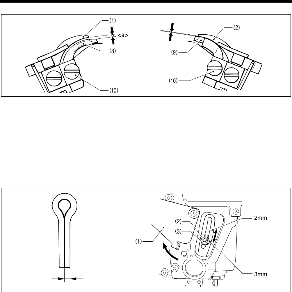
7. ADJUSTMENTS
RH-9820 142
Looper height
Adjust so that the positions of the eye looper (8) and the looper R (9) are as follows.
• The clearance <a> between the eye looper (8) and the spreader L (1) should be equal to the thickness of the lower thread
(looper thread).
• The clearance between the looper R (9) and the spreader R (2) should be as small as possible (so that the two parts do not
touch).
<Adjustment method>
1. Loosen the set screws (10), and then move the eye looper (8) or the looper R (9) up or down to adjust.
2. Check that the spreader L (1) and the spreader R (2) move smoothly by the force of the springs (3).
3. Once adjustment is complete, securely tighten the set screws (10).
7-2. Adjusting the zigzag width (stitch width)
The zigzag width can be adjusted to between 1.5 - 4 mm. It is set to 3 mm at the time of shipment from the factory.
* If the zigzag width is set to 3.2 mm or more, replace the throat plate (optional part).
1. Turn the cover (1) to open it.
2. Use the accessory socket wrench to loosen the zigzag width adjustment nut (2).
3. Move the adjustment screw (3) up or down along the slot to adjust.
* The zigzag width becomes smaller as the adjustment screw (3) is moved upward.
* The zigzag width becomes larger as the adjustment screw (3) is moved downward.
* There are index marks at the 2 mm and 3 mm zigzag width positions. Align the middle of the adjustment screw (3) with the
index marks.
4. Once adjustment is complete, securely tighten the adjustment nut (2), and then close the cover (1).
NOTE:
• If the zigzag width has been increased, carry out the following readjustments.
“7-4. Adjusting the needle and looper timing”, “7-5. Adjusting the looper stroke”, “7-6. Adjusting the height of the needle bar”,
“7-7. Adjusting the clearance between the loopers and needle”, “7-8. Adjusting the needle guard”, “7-9. Adjusting the
spreader installation positions”, “7-10. Adjusting the spreader timing”.
• The index marks are a guide to the zigzag width. Lower the needle onto a piece of paper or similar to accurately measure
the zigzag width.
0483B
1.5mm - 4mm
0967Q 0474B
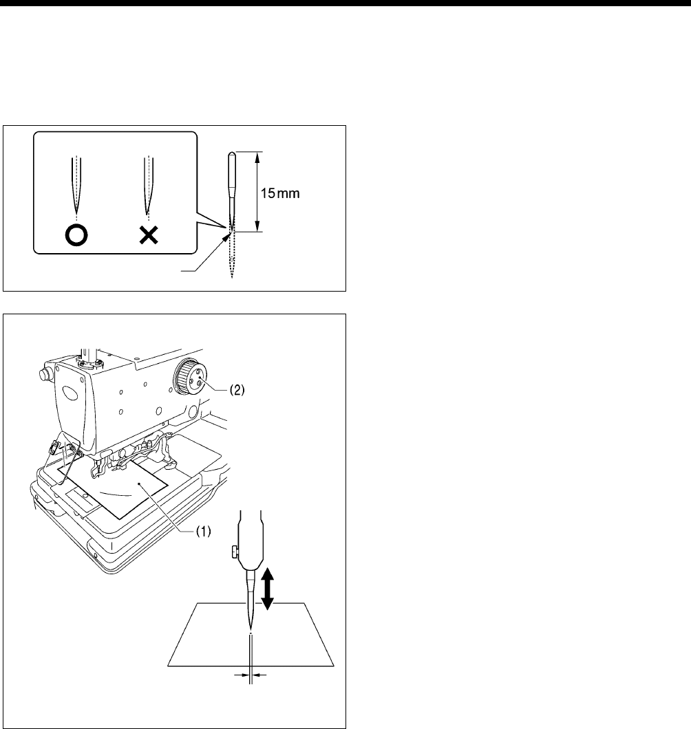
7. ADJUSTMENTS
RH-9820
143
7-3. Adjusting the zigzag base line position
Preparing a short customized needle
Prepare a short needle as described below in order to make very small holes in a piece of paper while checking the needle drop
position.
1. Use a grinder or similar to grind the tip of the
currently-used needle until the length of the needle is 15
mm.
2. Sharpen the tip of the needle.
NOTE:
Sharpen the needle so that the tip of the needle is in the
middle.
3. Place a piece of paper (1) underneath the work clamps.
4. Turn the upper shaft pulley (2) to set the needle to its
lowest position.
5. Move the needle up or down to adjust the installation
position of the needle so that the tip of the needle makes a
hole with a width of about 0.5 mm in the paper (1) when
the needle comes to the needle down position.
Hole width approx. 0.5 mm
0564B
Sharpen tip
0563B
middle middle
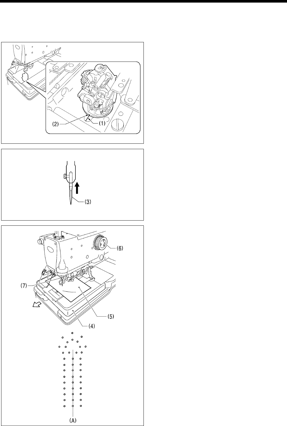
7. ADJUSTMENTS
RH-9820 144
Adjusting the zigzag base line position
The zigzag base line is on the inside of the zigzag.
If you change the zigzag width, only the outer needle drop position will change, and the zigzag base line (inner base line) will not
change.
1. Move the needle bar gear block (θ) to the home position.
* The home position for the needle bar gear block (θ) is
when the bed index mark (1) and the looper base index
mark (2) are aligned.
2. Install the short customized needle (3).
(Refer to “Preparing a short customized needle” on the
previous page.)
3. Move the feed base (4) forward (to near the sewing start
position) by hand.
4. Place a piece of paper (5) underneath the work clamps.
* Secure the piece of paper so that it will not move.
5. Turn the upper shaft pulley (6) to lower the needle so that it
makes a small hole in the paper (5).
6. Turn the upper shaft pulley (6) in reverse to return the
needle to its original position (needle up position).
7. Turn the needle bar gear block (needle bar) (7) by hand
180 degrees.
8. Turn the upper shaft pulley (6) to lower the needle so that it
makes a small hole in the paper (5).
* If the inner needle drop positions (A) are not aligned,
carry out the adjustments in steps 9 - 12 on the next
page.
(Continued on next page)
0475B
0431B
0329B
0562B
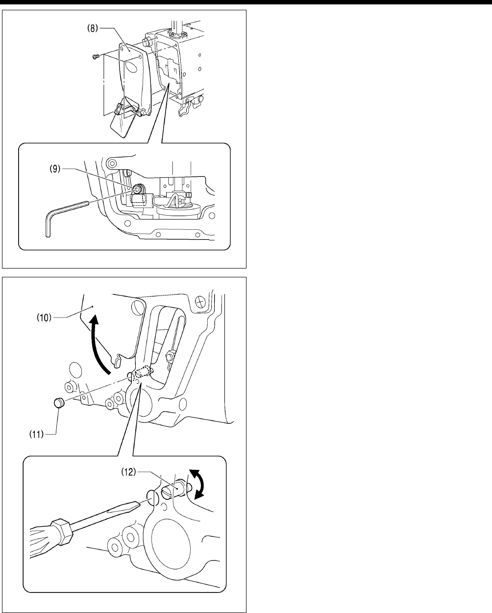
7. ADJUSTMENTS
RH-9820
145
<Zigzag base line position adjustment>
9. Remove the face plate (8), and then loosen the socket bolt
(9).
10. Open the cover (10), and then remove the cap (11).
11. Insert a flat-tipped screwdriver into the hole and turn the
zigzag eccentric pin (12) to adjust the zigzag base line
position.
12. Tighten the socket bolt (9).
13. Repeat steps 4 - 12 until the inner zigzag base line is
aligned correctly.
14. Once adjustment is complete, return the cap (11), cover
(10) and face plate (8) to their original positions.
0476B
0434B
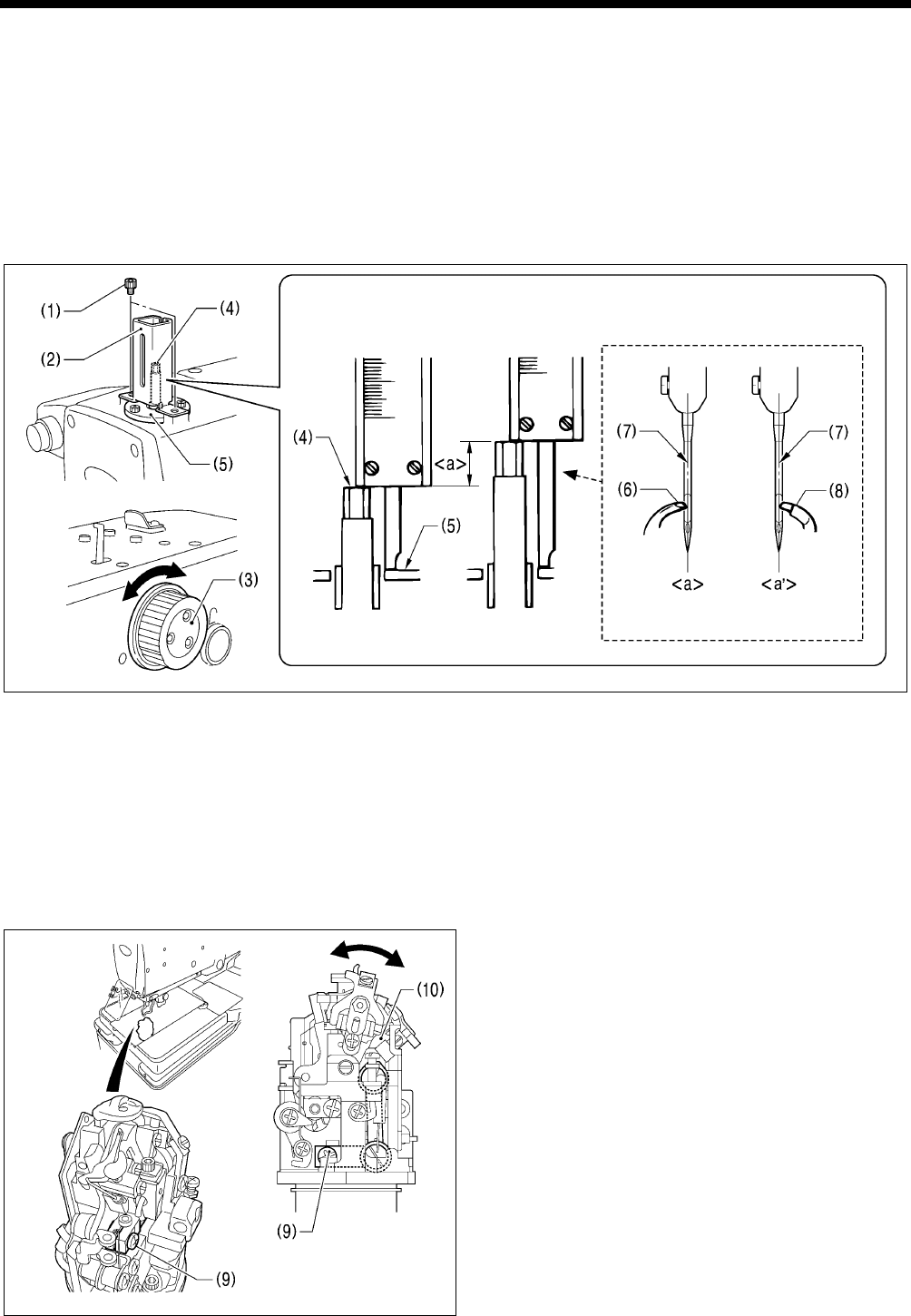
7. ADJUSTMENTS
RH-9820 146
7-4. Adjusting the needle and looper timing
NOTE:
The needle bar moves through two needle drop cycles for each single turn of the upper shaft pulley. The needle drop
movement toward the left side (knife cutting side) is called the “inside sewing position”, and the needle drop movement
toward the right is called the “outside sewing position”. In addition, the amount of movement involved when the needle bar
rises from its lowest position until the tip of the looper at either the left or right is aligned with the center of the needle is called
the “loop stroke”.
The left and right loop strokes must be the same as each other. This section describes the adjustments to be carried out so that
the left and right loop strokes are the same.
* Before carrying out these adjustments, set the zigzag width (stitch width). (Refer to “7-2. Adjusting the zigzag width (stitch
width)”.)
=
1. Remove the two socket bolts (1), an then remove the needle bar guard (2).
2. Turn the upper shaft pulley (3) to set the needle bar to its lowest position at the inside sewing position.
3. Use calipers to measure the length from the edge of the needle bar (4) to the top of the needle bar bush holder base (5).
4. Next, turn the upper shaft pulley (3) until the tip of the eye looper (6) is aligned with the needle center (7).
5. In the same was as in step 3, use calipers to measure the length from the edge of the needle bar (4) to the top of the needle
bar bush holder base (5).
6. Calculate the difference <a> between the value obtained in step 5 and the value obtained in step 3.
7. Repeat steps 2 - 6 and calculate the difference <a'> for the outside sewing position in the same way as for the inside sewing
position.
* For the inside sewing position, align the tip of the eye looper (6) with the needle center (7), and for the outside sewing
position, align the tip of looper R (8) with the needle center (7).
8. Loosen the screw (9).
9. Move the LS holder base (10) to the left or right to adjust
so that length <a> and length <a'> are the same.
10. Once adjustment is complete, securely tighten the screw
(9).
(Viewed from the front)
0484B
0487B 0488B
Lowest position
of needle ba
r
When center of needle is
aligned with tip of loope
r
(Inside sewing
position)
(Outside sewing
position)
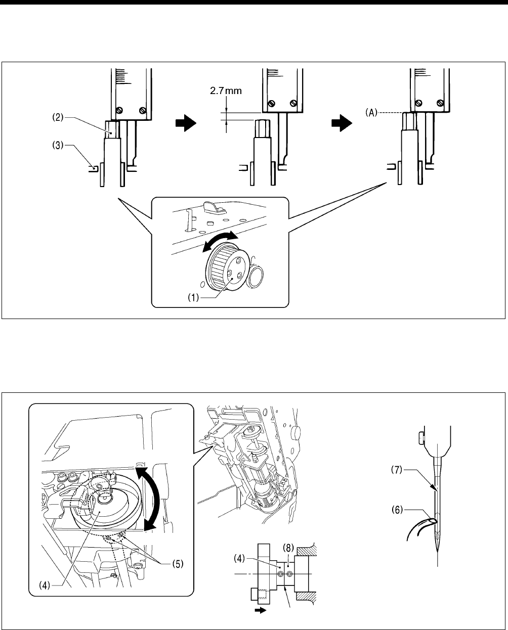
7. ADJUSTMENTS
RH-9820
147
7-5. Adjusting the looper stroke
The standard looper stroke is 2.7 mm. (It may be preferable to change this depending on the material and thread.)
* Carry out the adjustment in “7-4. Adjusting the needle and looper timing” before making this adjustment.
1. Turn the upper shaft pulley (1) to set the needle bar to the needle drop position at the inside sewing position.
2. At this position, use calipers to measure the length from the edge of the needle bar (2) to the top of the needle bar bush
holder base (3).
3. Add 2.7 mm to the value obtained in step 2 above, and set the width of the calipers to the resulting value.
4. Turn the upper shaft pulley (1) until the edge of the needle bar (2) touches the edge of the calipers, and stop turning the
upper shaft pulley (1) at that point (A).
Push against Should be no gap
5. Tilt back the machine head.
6. Loosen the two set screws (5) of the lower shaft cam (4).
7. With the upper shaft pulley (1) stopped, turn the lower shaft cam (4) to adjust so that the tip of the eye looper (6) is aligned
with the needle center (7).
8. Once adjustment is complete, push the lower shaft cam (4) against the surface of the bearing collar (8), and then securely
tighten the two set screws (5).
0327B 0491B0490B
0489B
Moves to left
Moves to right
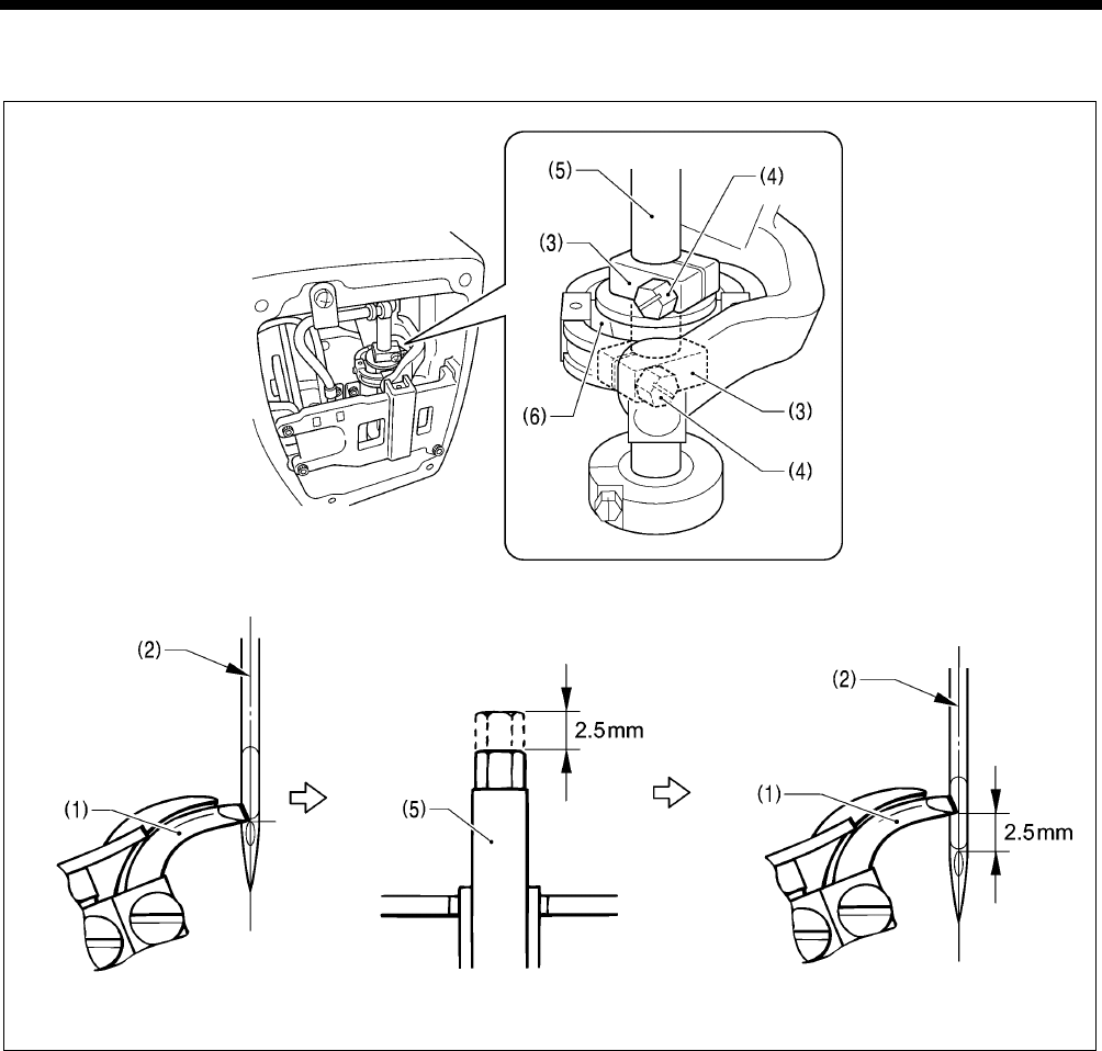
7. ADJUSTMENTS
RH-9820 148
7-6. Adjusting the height of the needle bar
The standard height for the needle bar is 2.5 mm. (It may be preferable to change this depending on the material and thread.)
1. Remove the face plate.
2. Turn the upper shaft pulley until the tip of the eye looper (1) is aligned with the top edge of the needle hole in the needle
center (2) when the needle is at the inside sewing position.
3. Loosen the two screws (4) of the top and bottom needle bar clamps (3).
4. Lower the needle bar (5) 2.5 mm from the position where the tip of the eye looper (1) is aligned with the top edge of the
needle hole.
5. In order to make the needle bar turn smoothly, adjust so that there is no play in the needle bar, but so that there is enough of
a gap between the needle bar clamps (3) and the needle bar feed rock link (6) for oil to get into.
6. Once adjustment is complete, securely tighten the two screws (4) and install the face plate.
0497B
0450B 0496B
0328B
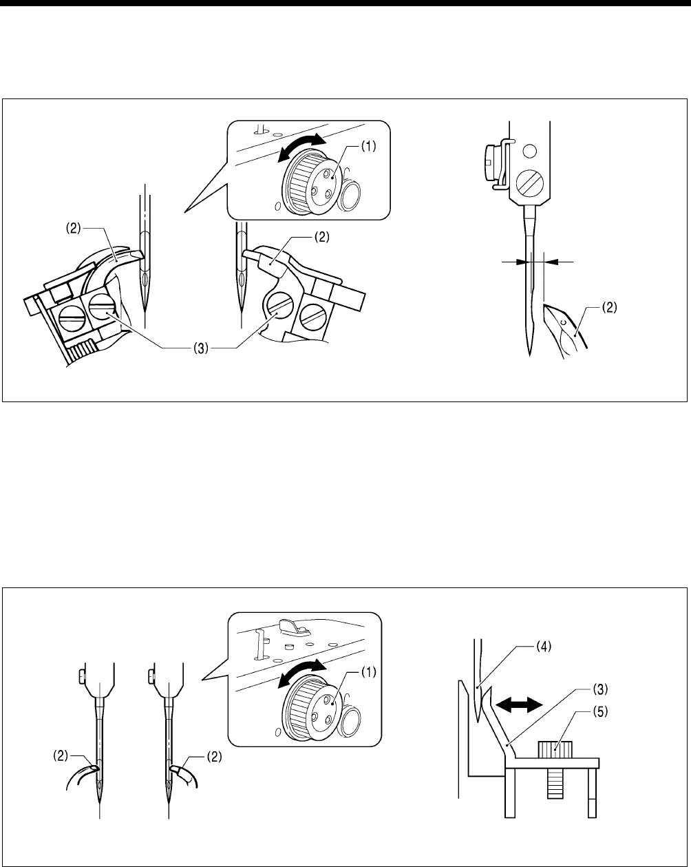
7. ADJUSTMENTS
RH-9820
149
7-7. Adjusting the clearance between the loopers and needle
If the needle count has been changed, always be sure to check the clearance between the needle and the loopers, and adjust
the clearances if necessary. These adjustments should be made for both the inside sewing position and outside sewing
position.
(Inside sewing position) (Outside sewing position)
Turn the upper shaft pulley (1) so that the tips of both the left and right eye loopers (2) are aligned with the needle center, and
then loosen the set screws (3) and adjust the clearances between the needle and the tips of the eye loopers (2) to 0.01 - 0.08
mm.
* These clearances must be uniform while the looper base is rotating (through 360 degrees). If they are not uniform, adjust
the center of rotation of the needle bar. (The center of rotation is already adjusted at the time of shipment from the factory.)
* After making this adjustment, carry out the adjustment procedures given in “7-9. Adjusting the spreader installation
positions”.
7-8. Adjusting the needle guard
If the needle count has been changed, always be sure to check the position of the needle guard, and adjust the position if
necessary. This adjustment should be made for both the inside sewing position and outside sewing position.
(Inside sewing position) (Outside sewing position)
Turn the upper shaft pulley (1) so that the tips of both the left and right loopers (2) are aligned with the needle center, and then
loosen the screw (5) and adjust the needle guard (3) so that it touches the needle (4).
NOTE:
If it crosses the needle more than necessary, it will place a load on the needle and this may cause the needle to break.
Alternatively, if it does not cross the needle at all, the tips of the loopers will interfere with the needle and skipped stitches
may occur.
0499B0498B
0493B
0492B
0.01 - 0.08mm
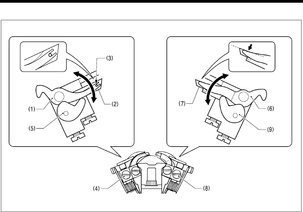
7. ADJUSTMENTS
RH-9820 150
7-9. Adjusting the spreader installation positions
1. Loosen the set screw (4) and adjust spreader stopper L (5) so that the relative positions of the U-shaped part at the tip of
spreader L (1) and the lower thread guide hole (3) in the eye looper (2) are as shown in the illustration below.
2. Once adjustment is complete, tighten the set screw (4).
3. Loosen the set screw (8) and adjust the spreader stopper R (9) so that the top edge of the tip of spreader R (6) is aligned
with the top edge of the tip of looper R (7).
4. Once adjustment is complete, tighten the set screw (8).
NOTE:
Spreader L (1) and spreader R (6) should not protrude above the eye looper (2) or looper R (7) respectively. If they do,
skipped stitches or needle breakages may occur.
0494B
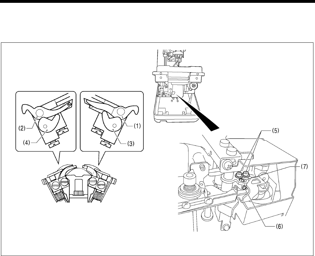
7. ADJUSTMENTS
RH-9820
151
7-10. Adjusting the spreader timing
Spreader R (1) (at inside sewing position) and spreader L (2) (at outside sewing position) must touch the spreader stoppers (3)
and (4) respectively and stop moving immediately before the needle bar reaches its lowest position.
* Adjustment can be carried out more easily if it is done in manual mode.
1. Tilt back the machine head.
2. Loosen the two screws (5), and then loose the set screw (6).
3. Turn the eccentric pin (7) to adjust.
4. After adjusting, tighten the set screw (6) and the two screws (5) in that order.
NOTE:
Make sure that spreader R (1) and spreader L (2) do not obstruct the needle after adjustment.
0501B0500B
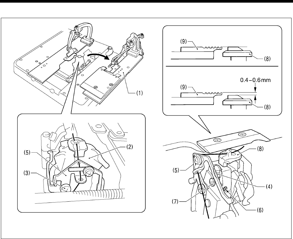
7. ADJUSTMENTS
RH-9820 152
7-11. Adjusting the height of the throat plate
<-00 and -01 specifications>
<-02 specifications>
(Viewed from the front)
(Viewed at an angle from above-right)
1. Remove the right-side work clamp plate (1).
2. Turn the looper base (2) so that it faces as shown in the illustration.
3. Loosen the screw (3), and then move gimp thread guide C (5) to a position where it will not obstruct turning of the screw (4).
4. Loosen the screw (4) by about 10 turns.
5. Loosen the set screw (6).
6. Move the vertical pin (7) to adjust the height of the throat plate (8) as follows.
<For -00 and -01 specifications>
Adjust so that the top of the throat plate (8) and the top of the needle plate (9) are at the same height.
<For -02 specifications>
Adjust so that the top of the throat plate (8) is 0.4 - 0.6 mm lower than the top of the needle plate (9).
NOTE:
• If the position of the throat plate (8) is too high, it may obstruct the movable knife and damage it.
• Press down gently on the throat plate (8) from above while adjusting it. If the adjustment is carried out while the throat
plate (8) is lifted up, the correct adjustment result will not be obtained.
7. Once adjustment is complete, tighten the screws that were loosened and return all other parts to their original positions.
0561B0560B
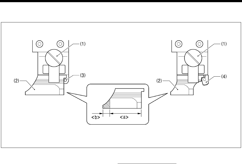
7. ADJUSTMENTS
RH-9820
153
7-12. Changing the cutting length (Replacing the hammer)
The cutting length is determined by the length of the hammer. File or replace the hammer in order to change the cutting length.
<For -00, -01, -02-L2634/L3442 specifications> <For -02-L1422/L1826/L2230 specifications>
1. Loosen the knob screw (1), and then remove the hammer (2).
2. [If grinding the hammer (Refer to Figure A)]
Use a grinder to grind section <b> of the hammer so that cutting length + 1.5 mm = <a>.
3. [If installing a new hammer]
Push the hammer against the positioning pin (3) (or the hammer spacer (4)), and then tighten the knob screw (1).
NOTE:
If the knife that was being used previously is replaced by a knife with a different number, replace the hammer also. If the
same hammer is used for two or more different types of knife, different knife incisions will be formed on the hammer, and this
may cause problems with the accurate cutting of the material or may damage the knife.
A
0463B
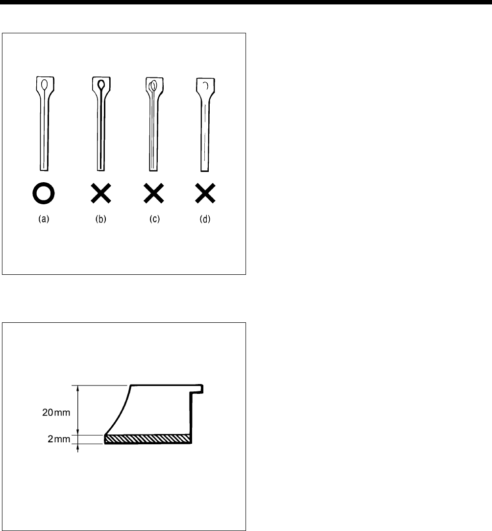
7. ADJUSTMENTS
RH-9820 154
7-13. Adjusting the cutting surface of the hammer
<Adjustment procedure>
1. Remove the hammer. (Refer to the previous page for
instructions on removing the hammer.)
2. Check the cutting surface of the hammer. Refer to the
illustration at left, and if the cutting surface looks like (b) -
(d), file the cutting surface so that the knife incision is
made evenly on the cutting surface.
(a) Knife incision is correct
(b) Knife incision is too deep
(c) A different knife was used which produced an
overlapping knife incision
(d) Partial knife incision which is not being made
completely
3. If the material cannot be cut cleanly even though the
hammer has been ground correctly, also check whether
the tip of the knife is worn.
* If the tip is worn, replace the knife.
* Do not use the old hammer after the knife has been
replaced. If the same hammer is used, it may damage
the tip of the knife.
7-13-1. Filing the cutting surface of the hammer
The cutting pressure over the whole of the hammer should be
uniform so that the material will be cut cleanly. File the cutting
surface of the hammer so that the knife incision will be uniform
over the whole of the hammer.
* The hammer can be filed until a height of 20 mm remains.
* Use a flat file for filing the hammer.
Filing the cutting surface of the hammer on which the
knife incision is overlapping or has shifted
1. Grip the hammer in a vise.
2. Use the flat file to file the cutting surface of the hammer
until the knife incision disappears.
Filing the cutting surface of the hammer in which knife
incision is deep
1. Grip the hammer in a vise.
2. Use the flat file to file the cutting surface of the hammer
smoothly until a single knife incision can still be seen
faintly.
* Once filing is complete, install the hammer.
0504B
0505B
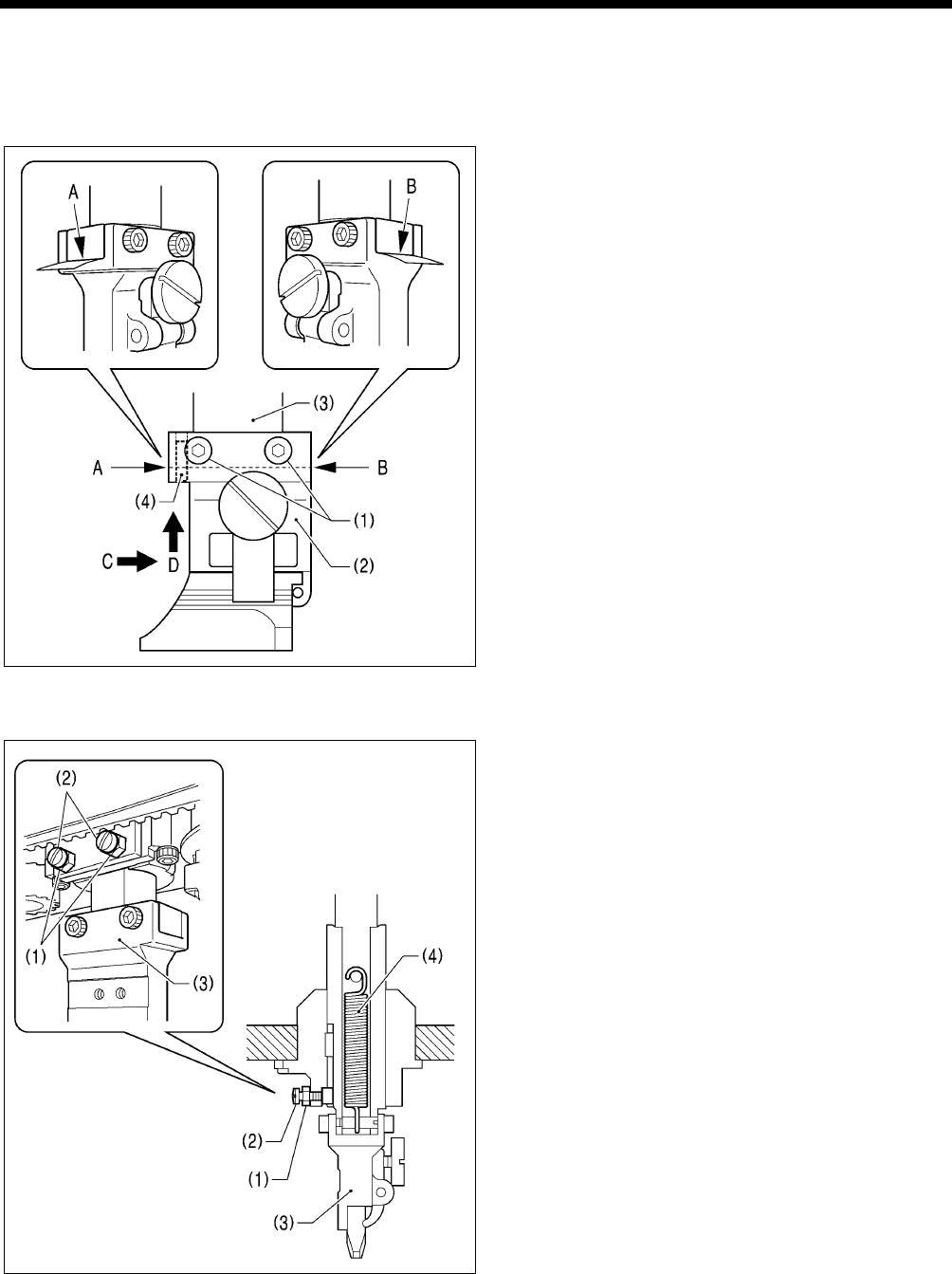
7. ADJUSTMENTS
RH-9820
155
7-13-2. Adjusting the contact between the knife and the hammer
The knife incision can be seen more clearly if the cutting surface of the hammer is filled over with a marker pen or similar.
1. Operate the hammer three times with the knife making a mark on it each time.
2. If the knife incision is not uniform, file the hammer. (Refer to the previous page for details on filing the hammer.)
3. Repeat steps 1 and 2 until the knife incisions are uniform.
<Contact adjustment method using thin paper>
The following method can also be used to adjust the contact.
1. Loosen the four screws (1).
2. Insert some thin paper into either of the gaps A or B
between the hammer bracket (2) and the cutter driving
shaft (3).
3. Tighten the four screws (1).
* Push the hammer bracket (2) in the direction of arrow
C and firmly upward in the direction of D shown in the
illustration so that there is no gap between the hammer
bracket (2) and the cutter driving shaft (3), and then
tighten the screws.
(This operation will position the hammer bracket (2))
accurately by pushing the pin (4) of the hammer
bracket (2) against the hole side of the cutter driving
shaft (3).)
7-14. Adjusting the axial play of the hammer
If there is too much axial play in the hammer, carry out the
following adjustment.
1. Loosen the two nuts (1).
2. Tighten the two screws (2) slightly to adjust while checking
the amount of play.
3. When the hammer bracket (3) is pushed downward by
hand, check that the built-in extension spring (4) causes it
to return correctly.
* If the hammer bracket (3) does not return correctly, it
may obstruct the work clamps and damage may result.
4. Once adjustment is complete, tighten the two nuts (1).
0464B
0470B
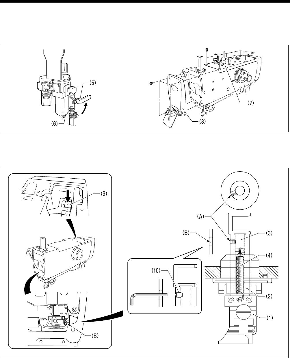
7. ADJUSTMENTS
RH-9820 156
7-15. Making the cutter driving shaft and driving shaft presser move together
The cutter driving shaft (2) and driving shaft presser (3) are linked by an extension spring (4) so that the hammer bracket (1) can
be positioned by being pushed down by hand when aligning the needle with an eyelet buttonhole that has already been made
in the material in order to resume sewing. If this extension spring (4) has been damaged, or if the return speed of the cutter is
too slow, the cutter driving shaft (2) and the driving shaft presser (3) can be made to move together as a single unit.
1. Turn the cock (5) in the direction of the arrow to close it and stop the supply of air.
2. Press the button (6) to release the air.
NOTE:
When the air is released, the hammer may lower by its own weight.
3. Remove the upper cover (7) and the face plate (8).
4. Lower the cylinder rod (9) to align the screw (A) of the cutter driving shaft (2) with (B) inside the face plate.
5. Use a commercially-available set screw (6) (M6 with a length of 6mm or less) to secure (A) and (B) together.
* Tighten the set screw (10) securely. If the set screw (10) is loose and protrudes from the surface of the cutter driving shaft
(2), damage may result.
6. Install the face plate (8) and the upper cover (7), and then open the cock (5) to resume the supply of air.
0502B 0503B
0472B0473B
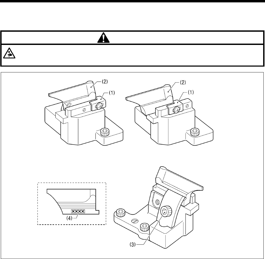
7. ADJUSTMENTS
RH-9820
157
7-16. Replacing the knife and adjusting its position
7-16-1. Replacing the knife
CAUTION
Do not operate the sewing machine while a knife and hammer with numbers that are different from those which have
been set in programs.
If this is not observed, damage to sewing machine parts or the needle or serious injury may occur.
<For -00, -01, -02-L2634/L3442 specifications> <For -02-L1422/L1826/L2230 specifications>
1. Check that there is no gap between the block stopper plate (1) and the knife (2), and then loosen the socket bolt (3) and
remove the knife (2).
2. Place the new knife to be installed against the block stopper plate (1), and then tighten the socket bolt (3).
NOTE:
• When replacing the knife, use the parameter settings to change the eyelet pattern to the pattern that corresponds to the
knife number (4) that is given on one side of the knife. (Refer to “5-3-1. Parameter list” in the instruction manual.)
• Replace the knife and hammer as a set. If the same hammer is used for two or more different types of knife, different knife
incisions will be formed on the hammer, and this may cause problems with the accurate cutting of the material or may
damage the knife.
0466B 0468B
0467B
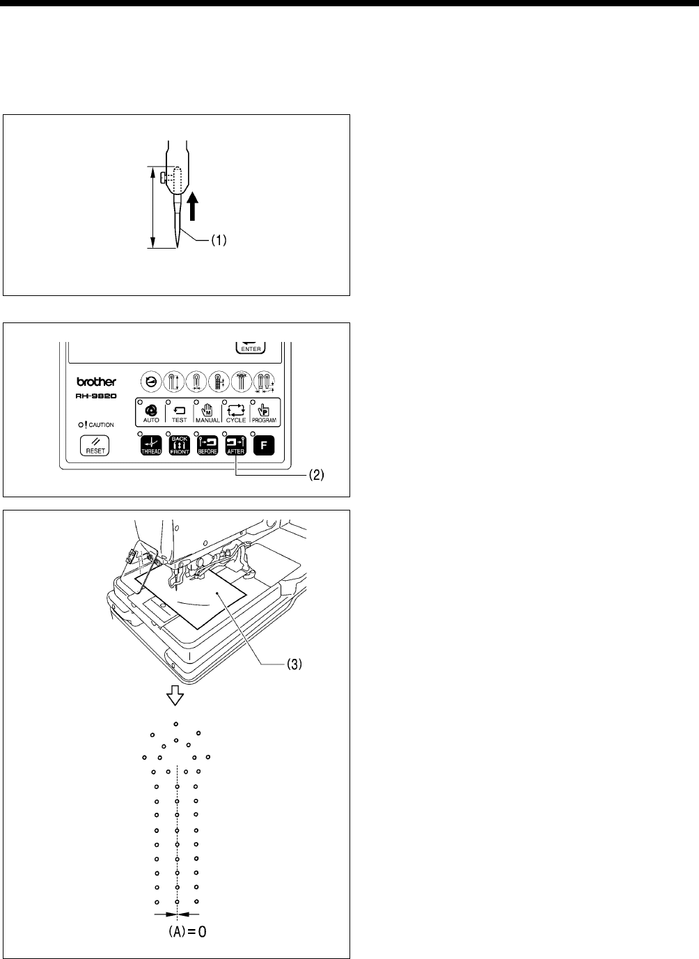
7. ADJUSTMENTS
RH-9820 158
7-16-2. Making fine adjustments to the knife position
Adjust the knife position so that it cuts the material cleanly at the inside sewing position and around the eyelet.
* Before carrying out this adjustment, check that the procedure in “7-3. Adjusting the zigzag base line position” has been
completed correctly.
* The knife position can be adjusted independently in the forward/back direction and tilt direction.
<Adjustment procedure>
1. Install the short customized needle (1).
(Refer to “7-3. Resetting the data (initialization)” in the
instruction manual for details on the short customized
needle (1).)
2. Set the air pressure at the hammer pressure adjustment
regulator on the underside of the table to about 0.2 MPa.
(Refer to “7-17. Adjusting the cutting pressure”.)
* This is so that the knife will not make several
overlapping incisions in the hammer and so that the
paper for checking the needle drop does not become
pierced while adjusting the knife position.
3. Press the AFTER key (2) on the operation panel to set the
cutting method to “cutting after sewing”.
4. Place a piece of paper (3) underneath the work clamps.
5. Start the sewing machine and trace the needle drop
position around the eyelet hole.
6. Check that the needle drop positions around the eyelet
hole and the knife cutting position overlap uniformly.
* Checking will be easier if the cutting position value (A)
in the parameter settings is set to “0”. (Refer to “5-3-1.
Parameter list” in the instruction manual.)
7. If they do not overlap uniformly, turn off the power and
carry out the adjustment in steps 8 - 13.
* Once adjustment is complete, repeat steps 4 - 6 to
check, and if further adjustment is needed, repeat step
7.
(Continued on next page)
0417B
0397B
0431B
0555B
15mm
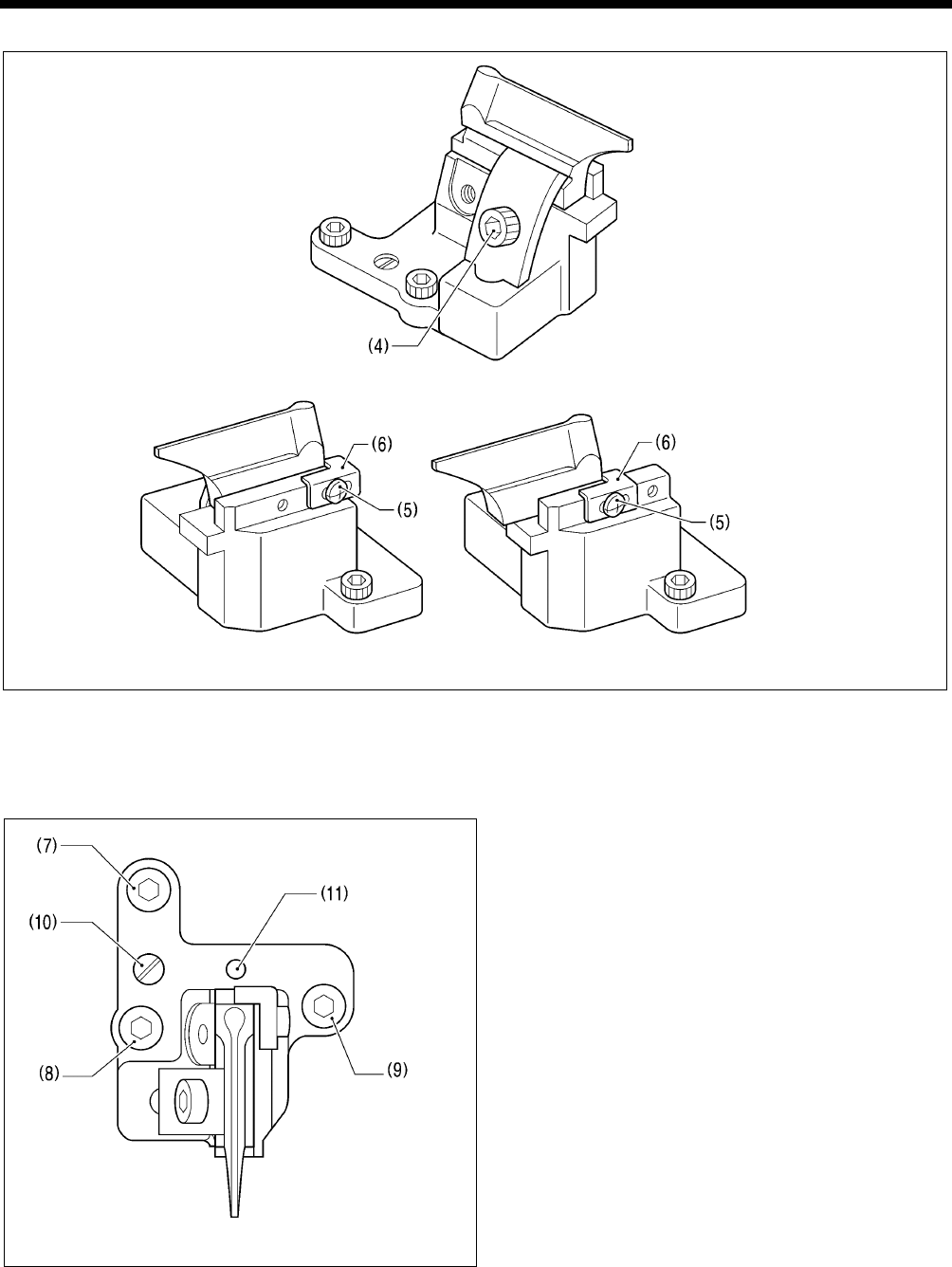
7. ADJUSTMENTS
RH-9820
159
<Forward/back position adjustment>
<For -00, -01, -02-L2634/L3442 specifications> <For -02-L1422/L1826/L2230 specifications>
8. Loosen the socket bolt (4), and move the knife position forward or back to adjust.
9. Once the knife position has been determined, securely tighten the socket bolt (4).
10. Loosen the screw (5), push the block stopper plate (6) against the knife, and then tighten the screw (5).
* The block stopper plate (6) is a guide for showing the current position of the knife, so be sure to move the block stopper
plate (6) so that it is touching against the knife.
<Tilt adjustment>
11. Loosen the socket bolts (7), (8) and (9).
12. Turn the eccentric pin (10) to adjust.
* Fine adjustments can also be made by turning
centering on the pivot (11).
13. Once adjustment is complete, tighten the socket bolts (9),
(8) and (7) in that order.
(Viewed from directly above the knife base)
0557B
0556B
0558B
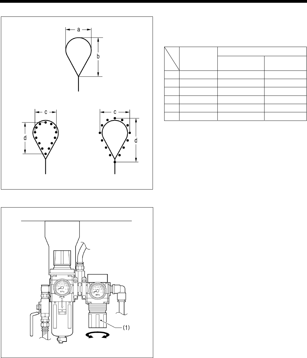
7. ADJUSTMENTS
RH-9820 160
NOTE: Relationship between needle drop position and eyelet pattern at the eyelet
When switching between cutting before sewing or no cutting
and cutting after sewing, the needle drop position at the inside
sewing position will change automatically in accordance with
the eyelet pattern as shown in the illustration.
Needle drop c x d
Knife
No.
Eyelet pattern
a x b Cutting before
sewing or no cutting
Cutting after
sewing
1 2.1 x 3.2 1.7 x 2.7 2.5 x 3.8
2 2.8 x 4.3 2.4 x 3.9 3.2 x 4.9
3 3.0 x 4.6 2.6 x 4.1 3.4 x 5.2
4 3.2 x 5.4 2.8 x 4.9 3.6 x 6.0
5 Straight Straight Straight
6 3.8 x 4.3 3.4 x 3.8 4.2 x 4.9
Cutting before sewing Cutting after sewing
7-17. Adjusting the cutting pressure
Set the cutting pressure to the minimum pressure that still
allows the material to be cut.
* Set to between 0.1 - 0.6 MPa. (It is set to 0.4 MPa at the
time of shipment from the factory.)
<Adjustment method>
Turn the knob (1) of the hammer pressure adjustment
regulator on the underside of the table to adjust the air
pressure.
NOTE:
• Do not increase the cutting pressure more than necessary.
If the pressure is too high, it will wear out the hammer and
damage the knife.
• If the material cannot be cut cleanly, do not increase the
cutting pressure to too high a pressure.
Check the timing between the knife and the hammer.
(Refer to “7-13-2. Adjusting the contact between the knife
and the hammer”.)
0559B
Eyelet pattern a x b
Needle drop c x d
0469B
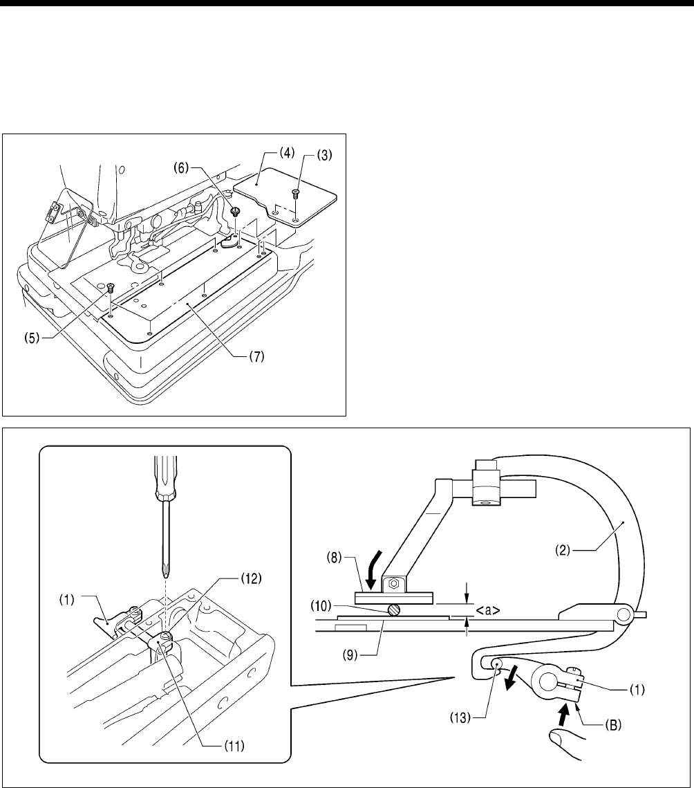
7. ADJUSTMENTS
RH-9820
161
7-18. Adjusting the work clamp lift amounts
Adjust the work clamp lift amount <a> to one of the values given below.
<For -00, -01 specifications>: 12 mm
<For -02 specifications>: 16 mm
* The work clamp lift amount <a> is the value which includes the play in crank lever B (1) and the clamp lever (2).
* Carry out adjustment for both the left and right work clamps. (The following describes how to adjust the lift amount for the
right-side work clamp.)
1. Remove the two screws (3), and then remove feed base
cover U (4).
2. Remove the six screws (5) and the shoulder screw (6),
and then remove feed base cover R (7) at the right side.
(Viewed from directly to the right)
3. Insert a block with a thickness of 12 mm or 16 mm or a gauge (10) in between the support point of work clamp R (8) and the
needle plate (9).
4. Loosen the screw (12) of the clamp driving lever (11).
5. Push section (B) of crank lever B (1) upward so that the tip (13) is pressed against the end of clamp lever R (2) as shown in
the illustration.
6. While holding the parts in the position in step 5, tighten the screw (12).
NOTE:
Check that work clamp R (8) is pressed securely against the block or the gauge (10).
7. Install feed base cover R (7) and feed base cover U (4).
* Adjust the lift amount for the left-side work clamp in the same way.
0508B
0509B
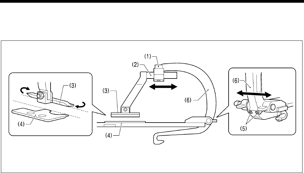
7. ADJUSTMENTS
RH-9820 162
7-19. Adjusting the work clamp positions
The positions of the work clamps relative to the needle plate can be adjusted forward, back and sideways.
* Adjust the left and right work clamps so that they are both positioned at an equal distance from the needle drop position.
(The following describes how to adjust the position of the right-side work clamp.)
(Viewed from directly to the right)
<Forward/back adjustment>
1. Loosen the socket bolt (1), and then move the position of the clamp arm (2) forward or back to adjust.
2. Next, adjust so that the side of work clamp R (3) is parallel to the side of the needle plate (4).
3. Once adjustment is complete, tighten the socket bolt (1).
<Sideways adjustment>
1. Loosen the two set screws (5), and then adjust the sideways position of the clamp lever (6).
2. Once adjustment is complete, tighten the two set screws (5).
* Adjust the position for the left-side work clamp in the same way.
0511B
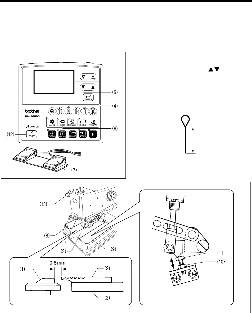
7. ADJUSTMENTS
RH-9820
163
7-20. Adjusting the positions of the work clamp plates
Adjust the positions of the work clamp plates (3) so that the throat plate (1) and needle plates (2) do not touch during sewing.
The standard adjustment is when there is a gap of 0.8 mm between the throat plate (1) and the needle plates (2) (when the
cutting space is set to "0").
* Carry out adjustment for both the left and right work clamps. (The adjustment method described below is for the position of
the right-side work clamp plate (3).)
* Carry out adjustment with the work clamp plates (3) installed.
1. Use the parameter settings to set the cutting space to “0”.
(Refer to “5-3-1. Parameter list” in the instruction manual.)
* If you press shortcut key 3 (4), you can then change
the value simply by pressing the / keys (5).
2. Press the TEST key (6) to turn on test mode, and then
start test operation. (Refer to “5-4. Checking the sewing
pattern in test mode” in the instruction manual.)
3. Press and hold the start switch (7) until the feed base
moves to the position where the straight section of the
sewing shape is sewn, and then release the start switch
(7).
Straight section
(when using a 2-pedal
foot switch)
Narrow gap
Wide gap
(Viewed from the front) (Viewed from directly above)
4. Check that there is a gap of 0.8 mm between the throat plate (1) and needle plate R (2).
5. If it is not 0.8 mm, remove feed bar cover L (8) and feed bar cover R (9), loosen the nut (10), and then turn the bolt (11) to
adjust the gap.
6. Once adjustment is complete, tighten the nut (10).
7. Press the RESET key (12), and then press the STOP switch (13) to end test mode.
* Adjust the gap between the throat plate (1) and needle plate L in the same way.
0462B
0512B
0513B
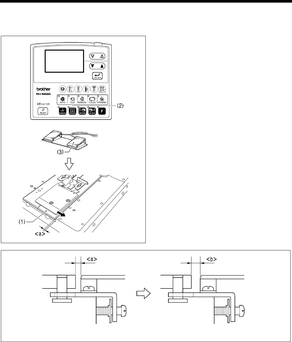
7. ADJUSTMENTS
RH-9820 164
7-21. Adjusting the cloth opening amounts
Adjust so that the opening amounts for the left and right work clamp plates (1) are equal.
* The cloth opening amounts should always be 0.8 mm or more on each side.
<Opening amount measurement method>
1. Press the TEST key (2) to turn on test mode, and then
start test operation. (Refer to “5-4. Checking the sewing
pattern in test mode” in the instruction manual.)
(When using a
2-pedal foot switch)
2. Depress the start switch (3).
* Check that the feed base moves and that the work
clamp plates (1) at left and right both open. This
opening amount is <a>.
Cloth opening amount = <b> - <a>
3. Use calipers to measure <a> (at both left and right).
4. Turn off the power for the sewing machine.
* The gap <a> will become wider. This opening amount is <b>.
5. Lower the work clamps, and then use calipers to measure <b> (at both left and right).
(Cloth opening amount = <b> - <a>)
6. Calculate the cloth opening amounts for both sides.
7. Carry out adjustment if the two cloth opening amounts are not the same, or if the cloth opening amount at either side is lower
than 0.8 mm. (Refer to following page.)
0517B
0515B
0516B
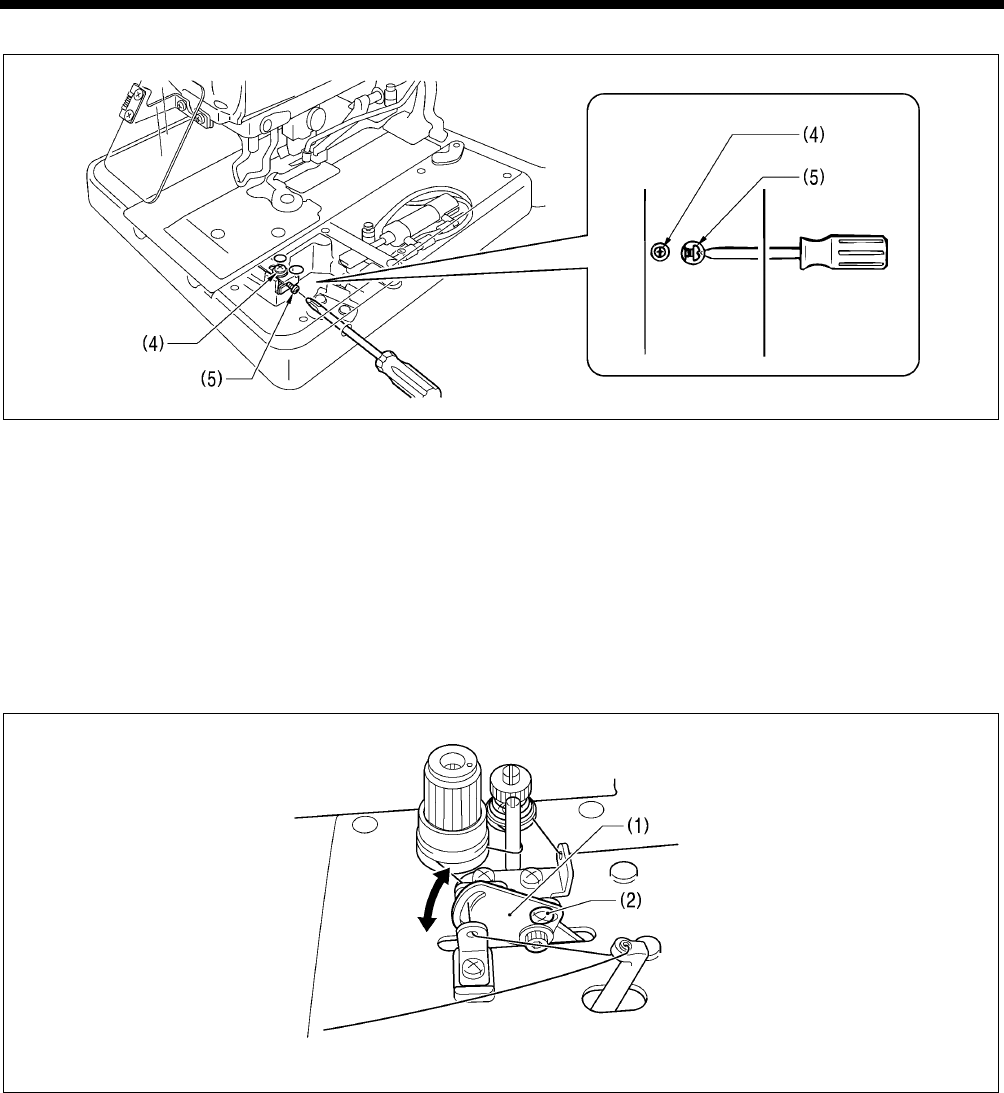
7. ADJUSTMENTS
RH-9820
165
<Cloth opening amount adjustment>
8. Loosen the screw (4).
9. Insert a screwdriver into the notch in the side of the feed base, and turn the adjustment screw (5) to adjust.
10. After tightening the screw (4), measure the opening amounts once more.
11. Repeat steps 2 - 10 until the left and right cloth opening amounts are equal to each other.
7-22. Adjusting the upper thread feeding amount
It is necessary for enough of an upper thread feeding amount to be maintained so that the amount of upper thread is sufficient
for stitches to be formed accurately at the sewing start.
NOTE:
The thread take-up lever (1) operates at the same time as sewing ends, and it stops operating at the same time as the feed
base starts moving when the start switch is pressed.
More thread
Less thread
1. Loosen the screw (2).
2. Move the thread take-up lever (1) up or down to adjust the upper thread feeding amount.
3. Once adjustment is complete, securely tighten the screw (2).
0477B
0518B
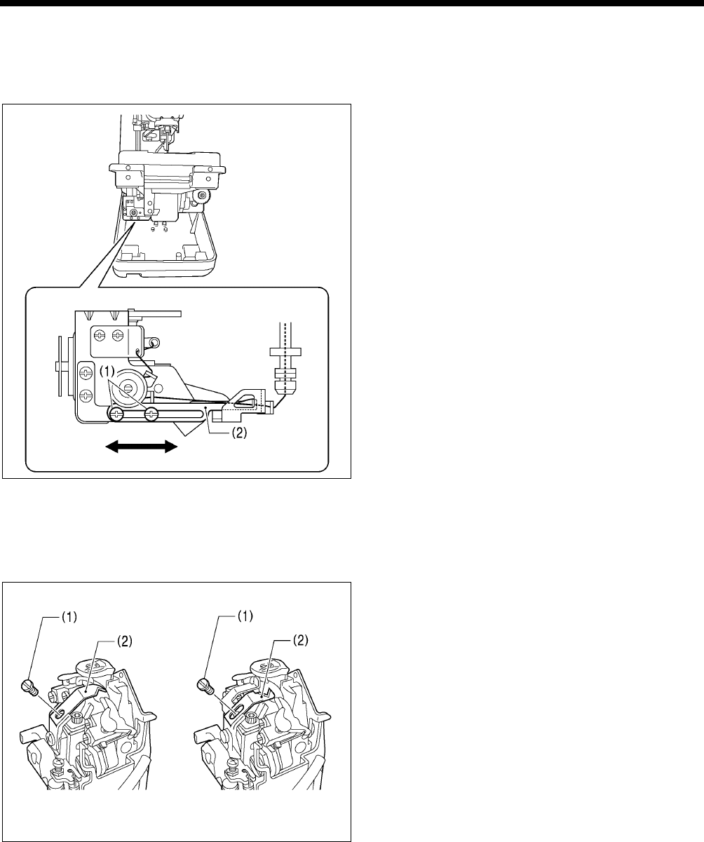
7. ADJUSTMENTS
RH-9820 166
7-23. Adjusting the lower thread feeding amount <-01 specifications only>
It is necessary for enough tension to be applied to the lower thread during the time from when the upper thread is picked up by
the eye looper at the first stitch until spreader L finishes opening, without the lower thread being pulled out by the thread nipper,
so that the first stitch can be sewn correctly at the sewing start.
1. After automatic sewing is finished, switch to manual mode
and then press the start switch. (Refer to “7-6. Manual
sewing (manual mode)” in the instruction manual.)
2. Turn the upper shaft pulley and check the condition of the
lower thread.
<If adjustment is necessary>
3. Turn off the power, and then tilt back the machine head.
4. Loosen the two screws (1), and then move lower thread
guide C (2) in the direction of the arrow to adjust.
* If it is moved to the right, the lower thread feeding
amount will increase, and if it is moved to the left, the
amount will decrease.
5. Once adjustment is complete, securely tighten the two
screws (1).
Becomes less Becomes more
7-24. Replacing and adjusting the upper movable knife
7-24-1. Replacing the upper movable knife
1. Remove the screw (1), and then remove the upper
movable knife (2).
2. Install the new upper movable knife with the screw (1).
<-00 and –01 specifications> <-02 specifications>
<-00 and -01 specifications> <-02 specifications>
0401B
0399B
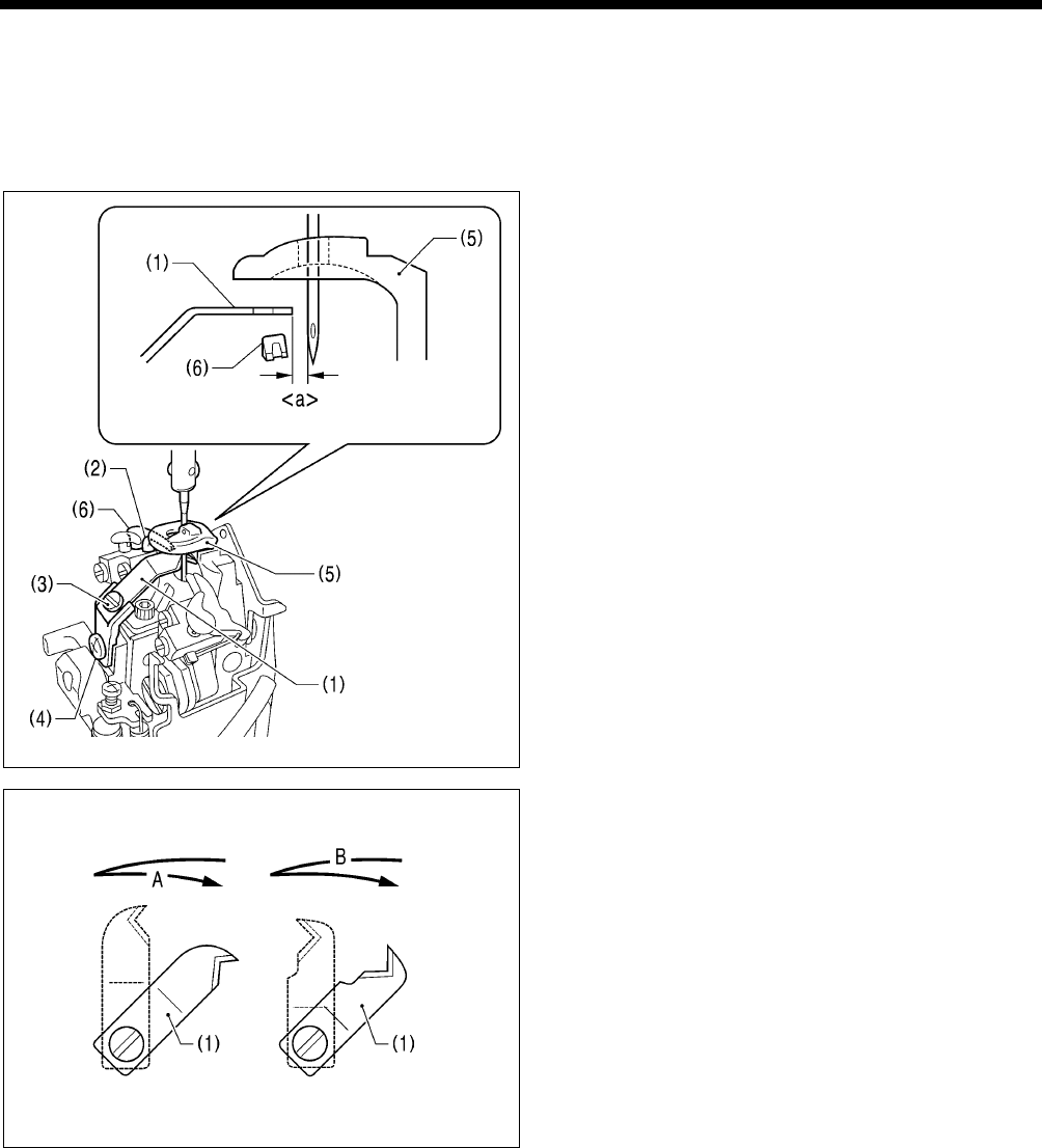
7. ADJUSTMENTS
RH-9820
167
7-24-2. Adjusting the upper movable knife
The upper movable knife (1) is adjusted so that only the upper thread that is in front of looper L (2) is cut. If two of the upper
thread loops (front and back) are cut, the upper thread trailing length will become too short and skipped stitches may occur at
the sewing start.
* If this adjustment is carried out in manual mode, the upper thread trimming operation can be checked step by step, which
will make adjustment easier.
1. Turn the upper shaft pulley to set the needle to the lowest
position at the outside sewing position.
2. Loosen the screw (3), and then adjust the gap <a>
between the tip of the upper movable knife (1) and the
needle to 0.1 - 0.4 mm.
3. Turn the upper shaft pulley to set the needle to its highest
position (needle up stop position) at the outside sewing
position.
4. Loosen the screw (4), and then adjust the position of the
upper movable knife (1) so that it is in between the throat
plate (5) and spreader L (6) without touching either of
them.
5. Move the upper movable knife (1) sideways by hand and
check that it does not touch either the throat plate (5) or
spreader L (6).
6. Once adjustment is complete, tighten the screws (4) and
(3) in that order.
NOTE: Upper thread trimming timing
<-00 and -01 specifications>
When the upper movable knife (1) has returned to its original
position, the upper thread is trimmed at position A.
<-02 specifications>
When the upper movable knife (1) starts moving, the upper
thread is trimmed at position B.
<-00 and -01 specifications> <-02 specifications>
0403B
(Viewed from directly to the right)
0565B
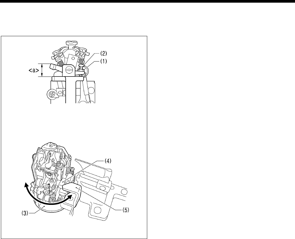
7. ADJUSTMENTS
RH-9820 168
7-24-3. Adjusting the position of the thread trimmer lever bracket
The position of the needle must be adjusted so that it does not obstruct the upper movable knife when it is at the maximum
zigzag width for the outside sewing position.
1. Loosen the nut (1).
2. Turn the screw (2) to adjust <a> in the illustration to 12
mm.
3. Turn the looper base (3) and check that the thread trimmer
lever bracket (4) moves underneath the thread trimmer
hammer (5) without obstructing any other parts.
4. Once adjustment is complete, securely tighten the nut (1).
(Viewed from the front)
0545B
0546B
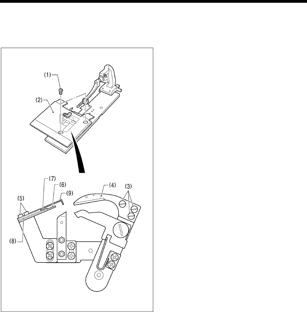
7. ADJUSTMENTS
RH-9820
169
7-25. Replacing and adjusting the movable knife and fixed knife (for the
lower thread and gimp) <-01 specifications>
7-25-1. Replacing the movable knife and fixed knife
1. Remove the two screws (1), and then remove work clamp
plate U (2).
<Movable knife replacement>
2. Remove the three screws (3), and then remove the
movable knife (4).
3. Install the new movable knife, and then tighten the three
screws (3).
<Fixed knife replacement>
4. Remove the two screws (5), and then remove the fixed
knife (6).
5. Install the new fixed knife (6), fixed knife plate spring (7),
fixed knife plate spring U (8) and thread guide plate (9) on
top of each other in that order, and then tighten the two
screws (5).
* After replacing the knives, carry out the adjustments from
“7-25-2. Adjusting the cutting pressure” to “7-25-5.
Adjusting the thread handler”. Once adjustment is
complete, install work clamp plate U (2).
0519B
0520B
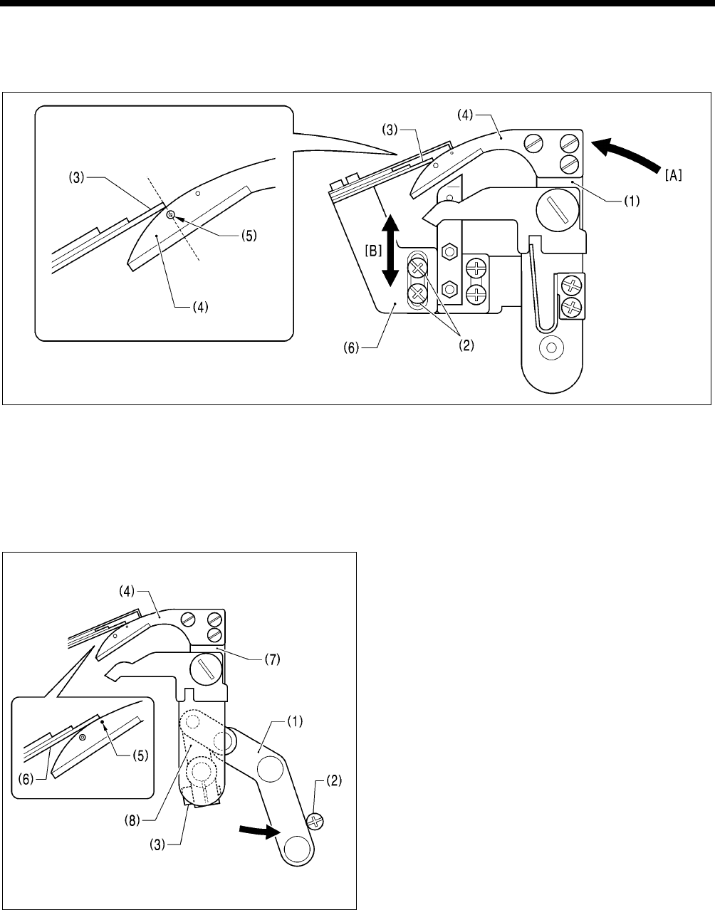
7. ADJUSTMENTS
RH-9820 170
7-25-2. Adjusting the cutting pressure
Adjust the cutting pressure to a suitable pressure so that the threads are trimmed cleanly.
NOTE:
Do not apply excessive pressure. Excessive pressure will cause the knives to become worn or damaged.
1. Push the thread trimmer arm (1) as far as it will go in the direction of the arrow [A].
2. Loosen the two screws (2).
3. With the thread trimmer arm (1) pushed as far as it will go, move the fixed knife setting bracket (6) along the guide groove in
the direction of arrow [B] to adjust so that the position where the tip of the fixed knife (3) and the movable knife (4) first start
touching is immediately above the mark (5).
4. Once adjustment is complete, securely tighten the two screws (2).
7-25-3. Adjusting the meshing amount
1. Turn the thread trimmer link lever (1) in the direction of the
arrow until it touches the screw (2).
2. Loosen the socket bolt (3).
3. Adjust the position of the thread trimmer arm (7) so that
the tip of the fixed knife (6) is directly above the index mark
(5) on the movable knife (4).
4. Once the adjustment is complete, securely tighten the
socket bolt (3).
NOTE:
• When tightening the socket bolt (3), check that the thread
trimmer lever arm (8) and the thread trimmer arm (7) move
smoothly with no play.
• If the meshing amount is too small, problems with the
lower thread nipper will occur and the thread will be pulled
out at the sewing start.
0522B
0521B
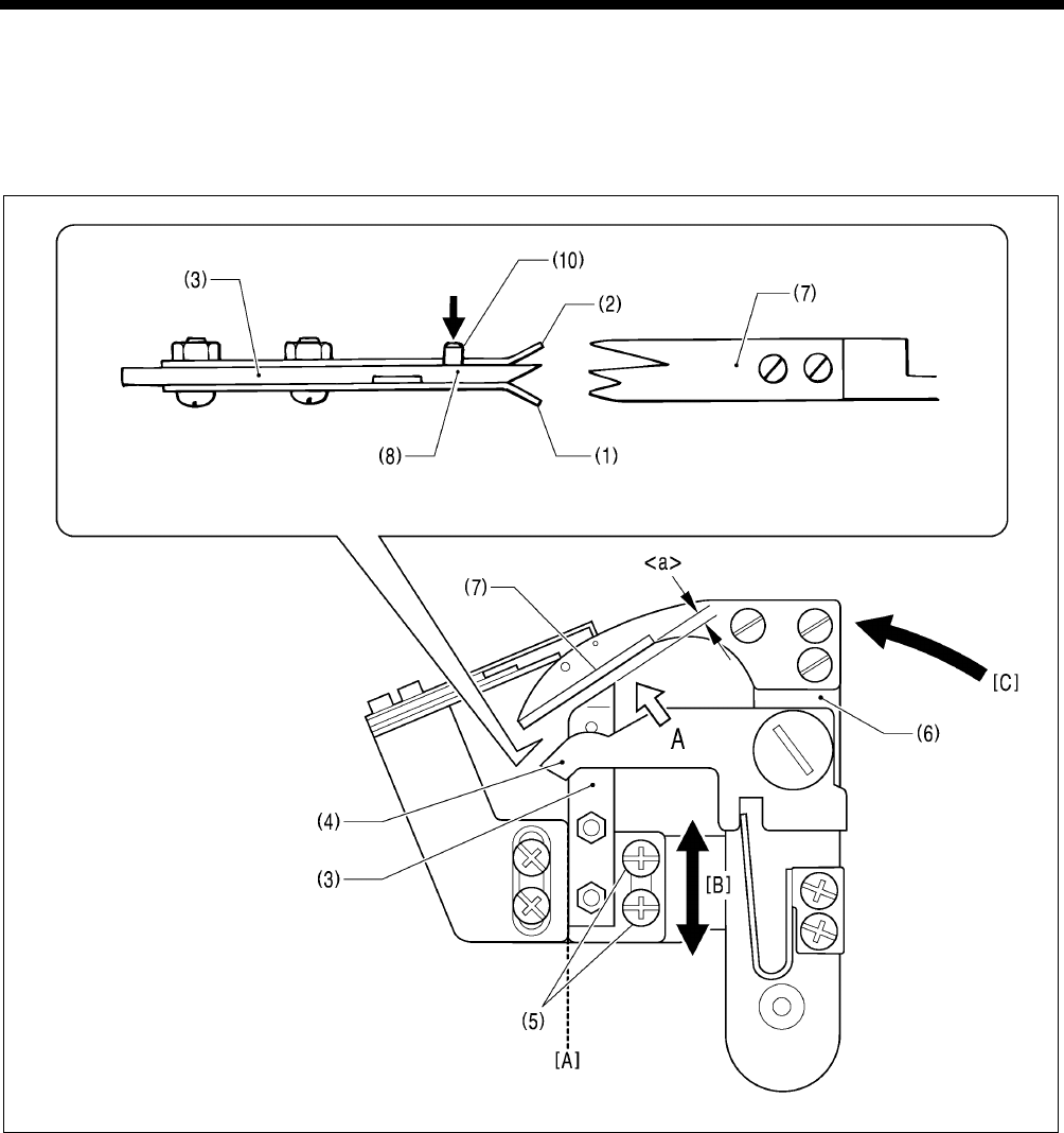
7. ADJUSTMENTS
RH-9820
171
7-25-4. Adjusting the thread nipper assembly and opener
The lower thread must pass through thread nipper D (1) and the gimp thread must pass through thread nipper U (2). Therefore,
check that the thread nipper assembly (3) is installed in the correct position and that the thread nipper opener (4) moves
correctly.
NOTE:
The lower thread must be securely held by thread nipper D (1) at the sewing start.
(Side view of thread nipper assembly (3) and the thread handler (7) viewed from position A)
1. Loosen the two screws (5), and then move the thread nipper assembly (3) along the dotted line [A] in the illustration in the
direction of the arrow [B] to adjust.
* Adjust so that the gap <a> between the thread nipper assembly (3) and the thread handler (7) is as narrow as possible
without the two parts touching when the thread trimmer arm (6) is turned in the direction of the arrow [C].
NOTE:
• If the gap <a> is too wide, problems with the lower thread nipper will occur and the thread will be pulled out at the sewing
start.
• If the thread nipper assembly (3) is installed at an angle, thread nipper D (1) may touch the throat plate and fail to open,
and problems with the lower thread nipper will occur and the thread will be pulled out at the sewing start.
0523B
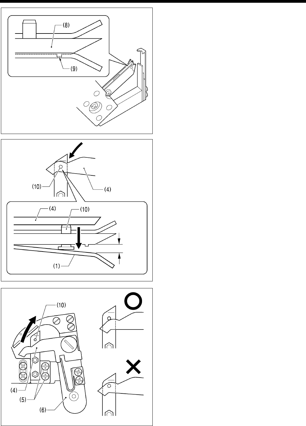
7. ADJUSTMENTS
RH-9820 172
2. The lower thread must go over the projection (9) on thread
nipper M (8) and be held securely. To make sure this
happens, check that the operations in (a), (b) and (c)
below are all correct.
(a) Thread nipper D (1) should open by 0.3 mm or more
when the thread nipper opener (4) pushes down on the
opener pin (10).
(b) Thread nipper D (1) should close immediately before
the thread is trimmed.
0.3 mm
or more
(c) Thread nipper D (1) should not open when the thread
trimmer arm (6) returns after thread trimming, so that
the thread nipper opener (4) returns without going over
the opener pin (10).
3. Once adjustment is complete, securely tighten the two
screws (5).
0552B
0553B
0554B
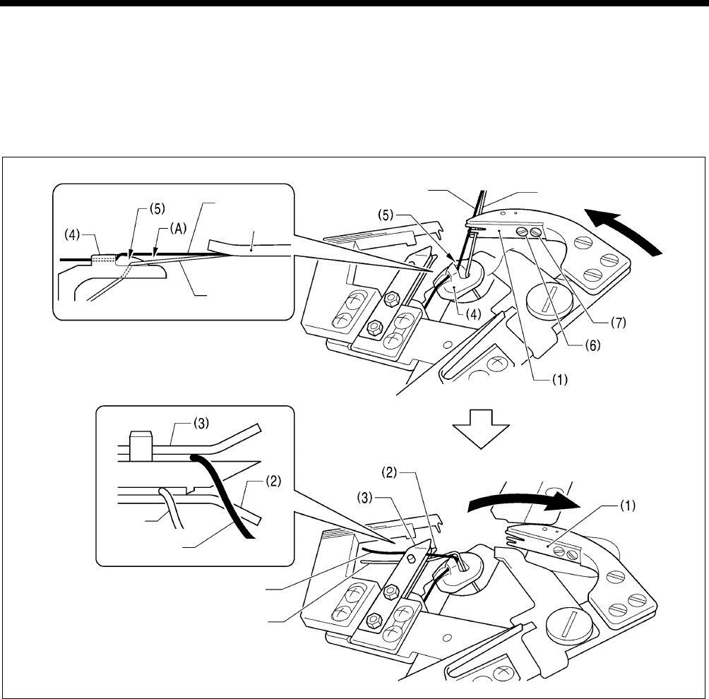
7. ADJUSTMENTS
RH-9820
173
7-25-5. Adjusting the thread handler
The lower thread and gimp are securely separated and guided by the thread handler (1), after which the lower thread needs to
go smoothly into thread nipper D (2), while the gimp needs to go smoothly into thread nipper U (3).
NOTE: Principle of the thread handler
When the thread trimmer arm operates, the throat plate (4) turns 45 degrees. This causes the gimp to sit on top of the
projection (5) of the throat plate (4) so that a difference in height is created between the lower thread and the gimp, and a
triangular shape (A) is formed between the two threads and the final stitch. The thread handler (1) goes into this triangular
shape (A) to separate the lower thread and gimp.
Gimp Lower thread
Gimp
Material
Lower thread
Gimp
Gimp
Lower thread
<Adjustment method>
* If this adjustment is carried out in manual mode, the lower thread trimming operation can be checked step by step, which will
make adjustment easier.
1. Use the parameter settings to set the stitch pitch to 2.0 mm and reduce the total number of stitches. (Refer to “5-3-1.
Parameter list” in the instruction manual.)
2. In manual mode, depress the start switch, and then turn the upper shaft pulley to sew manually as far as the final stitch.
(Refer to “7-6. Manual sewing (manual mode)” in the instruction manual.)
3. With the needle bar at the needle up stop position, depress the start switch one press at a time.
* The thread trimming operation will be carried out one step at a time.
4. Loosen the pan screw (6) and the screw (7), and then use the pan screw (6) as a pivot to turn the thread handler (1) to
adjust.
5. Once adjustment is complete, securely tighten the pan screw (6) and the screw (7).
NOTE:
If the height of the throat plate (4) has been changed, the triangular shape (A) defined by the final stitch, lower thread and
gimp will change, and so you should adjust the thread handler (1).
0525B
Lower
thread
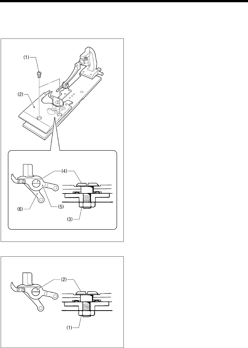
7. ADJUSTMENTS
RH-9820 174
7-26. Replacing and adjusting the movable knife and fixed knife (for the
lower thread and gimp) <-02 specifications>
7-26-1. Replacing the movable knife and fixed knife
1. Remove the two screws (1), and then remove work clamp
plate U (2).
2. Remove the nut (3).
3. Remove the shoulder screw (4), and then remove
movable knife L (5) and movable knife R (6).
4. Install the new knives, and then install the shoulder screw
(4).
5. Adjust the cutting pressure (see below), and then tighten
the nut (3).
6. Install work clamp plate U (2).
7-26-2. Adjusting the cutting pressure
Adjust the cutting pressure to the minimum pressure at which
thread trimming can be carried out cleanly.
1. Loosen the nut (1).
2. Turn the shoulder screw (2) to adjust the cutting pressure.
NOTE:
If the shoulder screw (2) is tightened as far as it will go,
the movable knives will no longer operate. Gradually
loosen the shoulder screw (2) to a point where the
movable knives turn smoothly.
3. Once adjustment is complete, securely tighten the nut (1).
0527B
0526B
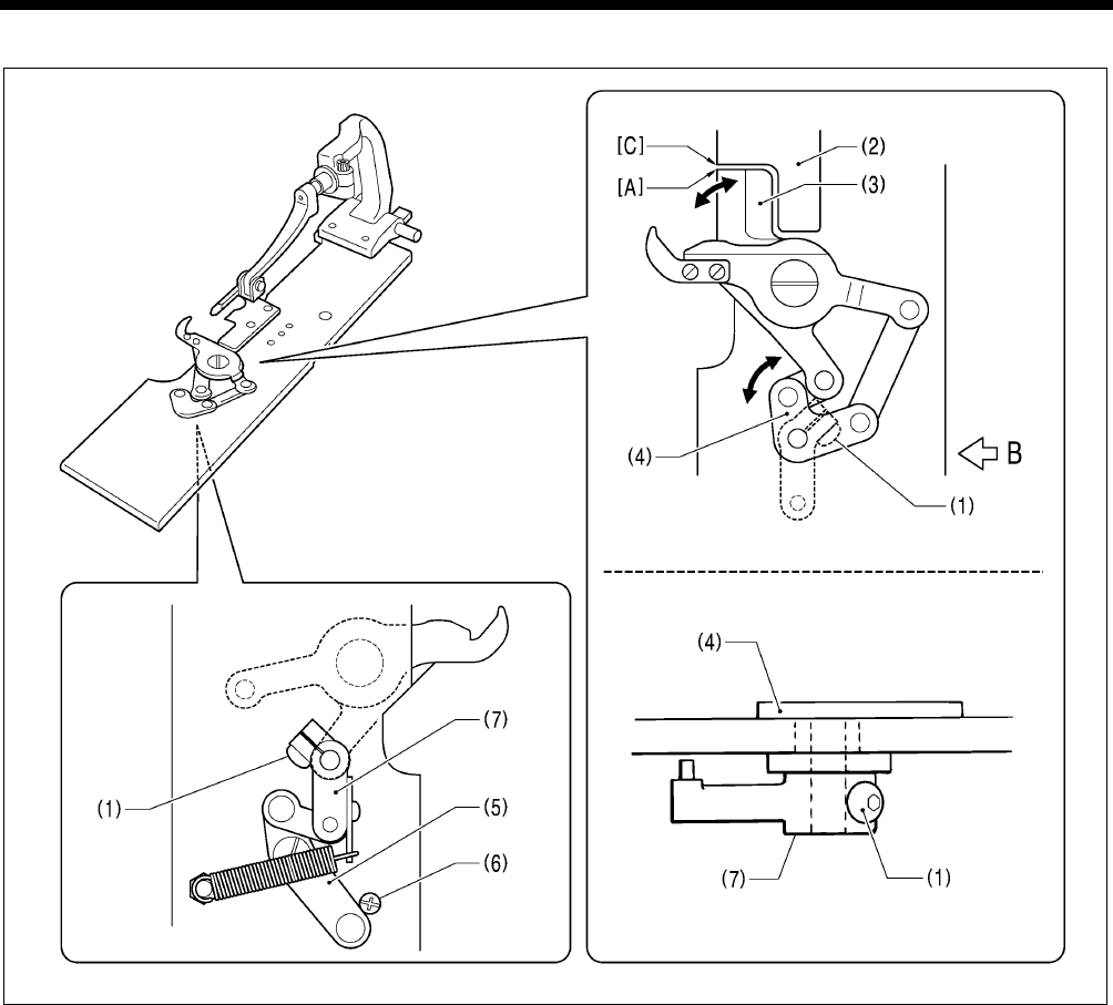
7. ADJUSTMENTS
RH-9820
175
7-26-3. Adjusting the movable knife installation position
(Viewed from directly above)
(Viewed from the side at position B)
1. Remove work clamp plate U. (Refer to “7-26-1. Replacing the movable knife and fixed knife”.)
2. Loosen the screw (1).
3. Turn the movable knife driving plate (4) so that the tip [A] of movable knife R (3) and the corner [C] of the needle plate (2) are
aligned.
4. Turn thread trimmer lever arm B (7) until the thread trimmer link lever J assembly (5) touches against the screw (6), and then
tighten the screw (1).
5. Once adjustment is complete, install work clamp plate U.
NOTE:
Check that the movable knife driving plate (4) and thread trimmer lever arm B (7) turn smoothly with no play.
0528B
(Viewed from underneath)
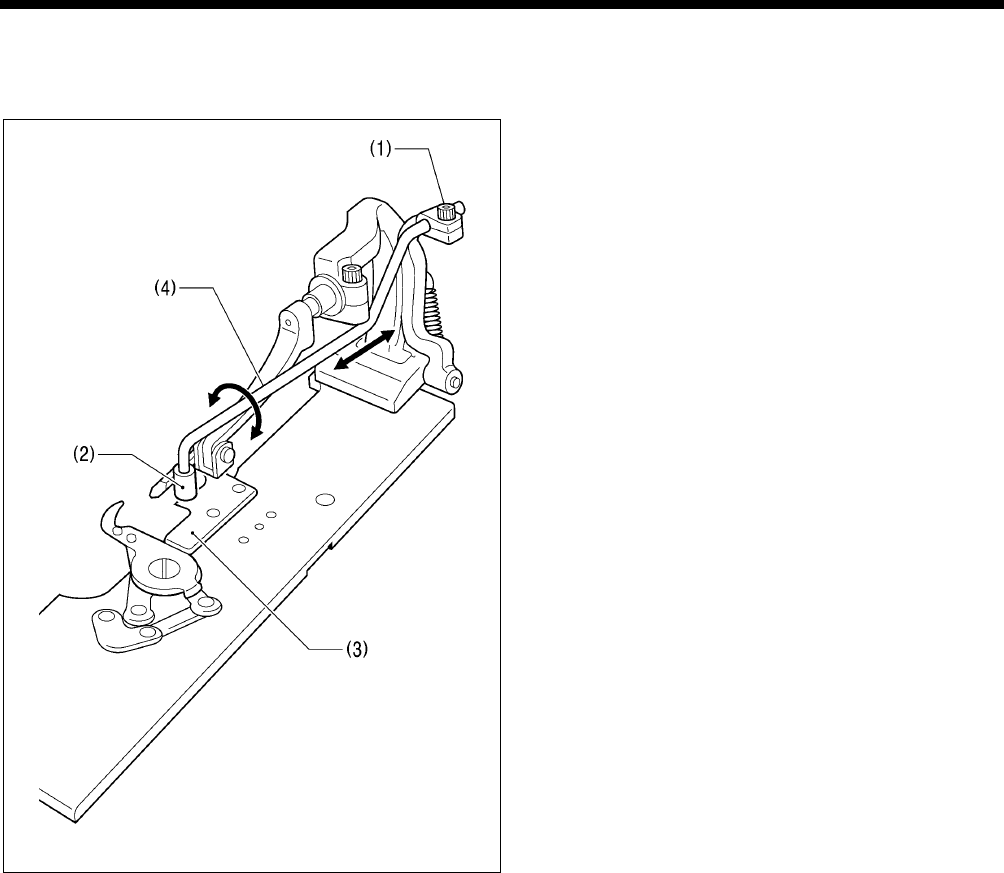
7. ADJUSTMENTS
RH-9820 176
7-26-4. Adjusting the position of the sub clamp
Trimming of the lower thread and gimp is carried out when the work clamps rise. The sub clamp ensures that the material does
not move during thread trimming, in order to maintain a stable thread length after trimming.
1. Loosen the socket bolt (1).
2. Adjust the installation position of the sub clamp wrist (4)
with respect to the article being sewn so that the button
clamp (2) moves above the needle plate (3).
3. Once adjustment is complete, securely tighten the socket
bolt (1).
0530B
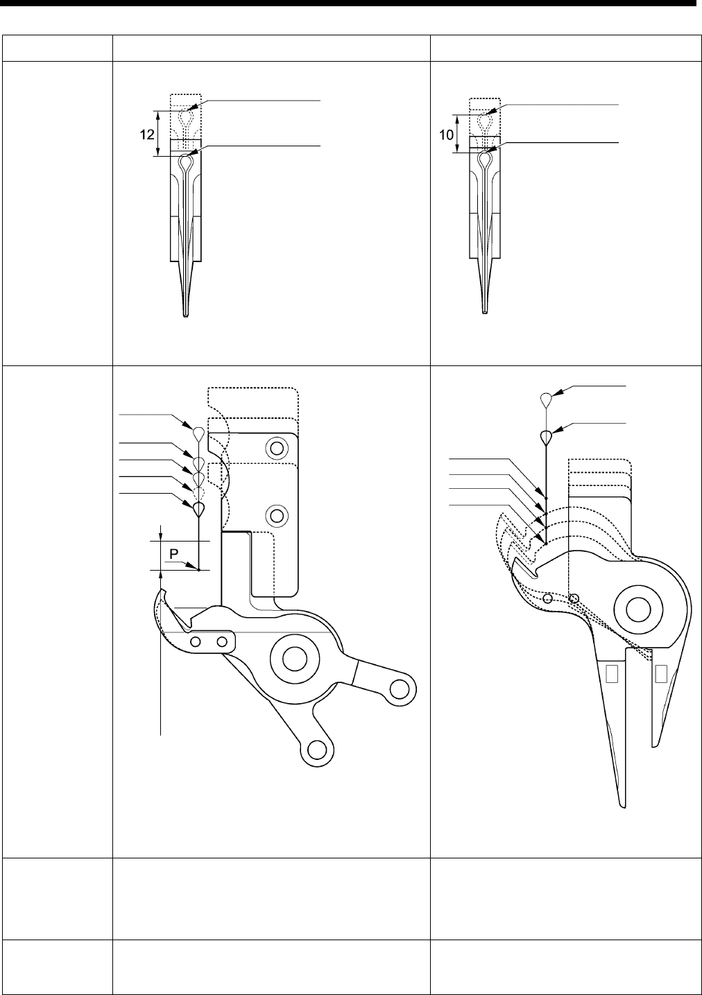
7. ADJUSTMENTS
RH-9820
177
7-26-5. Differences from older models
RH-9820 RH-981A
Knife installation
position
* In order to ensure
interchangeability with the
RH-981A hammer, install the
hammer spacer (SA6800-001) to
the hammer mounting bracket
when using a S-- hammer. (Refer
to “7-16-1. Replacing the knife”.)
* Because there is a shift of
10 mm, the S-- hammer is
offset.
Needle plate
position viewed
from work clamp
plate
Advantage: The left and right movable knives do not
need to be replaced.
Note:The feed base position when the material is set
back varies depending on the size.
Advantage: The feed base position when the
material is set back s the same
for all sizes.
L specifications
changed
(replacement
parts)
・Needle plate L and R
・Work clamp L and R
Total 4 points
・Needle plate L and R
・Movable knife L and R
・Specification harness
・Work clamp L and R
Total 7 points
Other settings Settings for memory switch No. 851 changed -
-00,-01
-02: L2634, L3442
-02:L1422,L2230
L1826
(Position when S
hammer is being used)
-00,-01
-02: L5, L6, L7
-02: L1, L2, L3, L4
(Position when S
hammer is being used)
L5, L6, L7
L1, L2, L3, L4
L1
L2
,
L5
L3, L6
L4, L7
1189B 1190B
1192B
Knife positions are aligned.
L3442
1191B
The maximum
lengths for each
size are aligned with
point P.
8 (Cutting range)
L2634
L2230
L1826
L1422
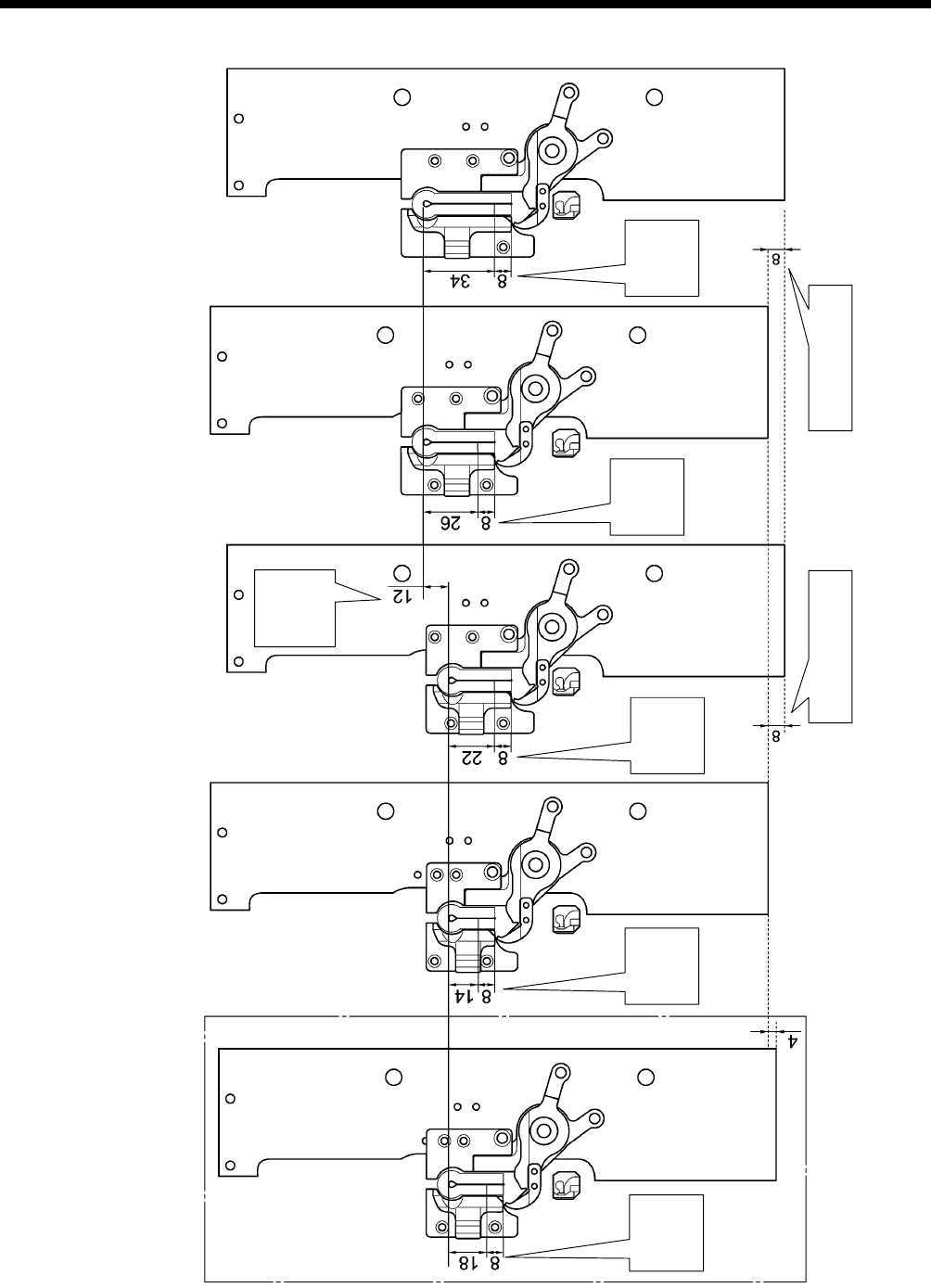
7. ADJUSTMENTS
RH-9820 178
L1422 L2230 L2634
L3442
NOTE:
When the material is set back and when the knife is lowered, the position of the feed base varies depending on L specifications (size).
Knife
position
shifted
Feed base shifted Feed base shifted
L1826
Cutting
range
Cutting
range Cutting
range
Cutting
range Cutting
range
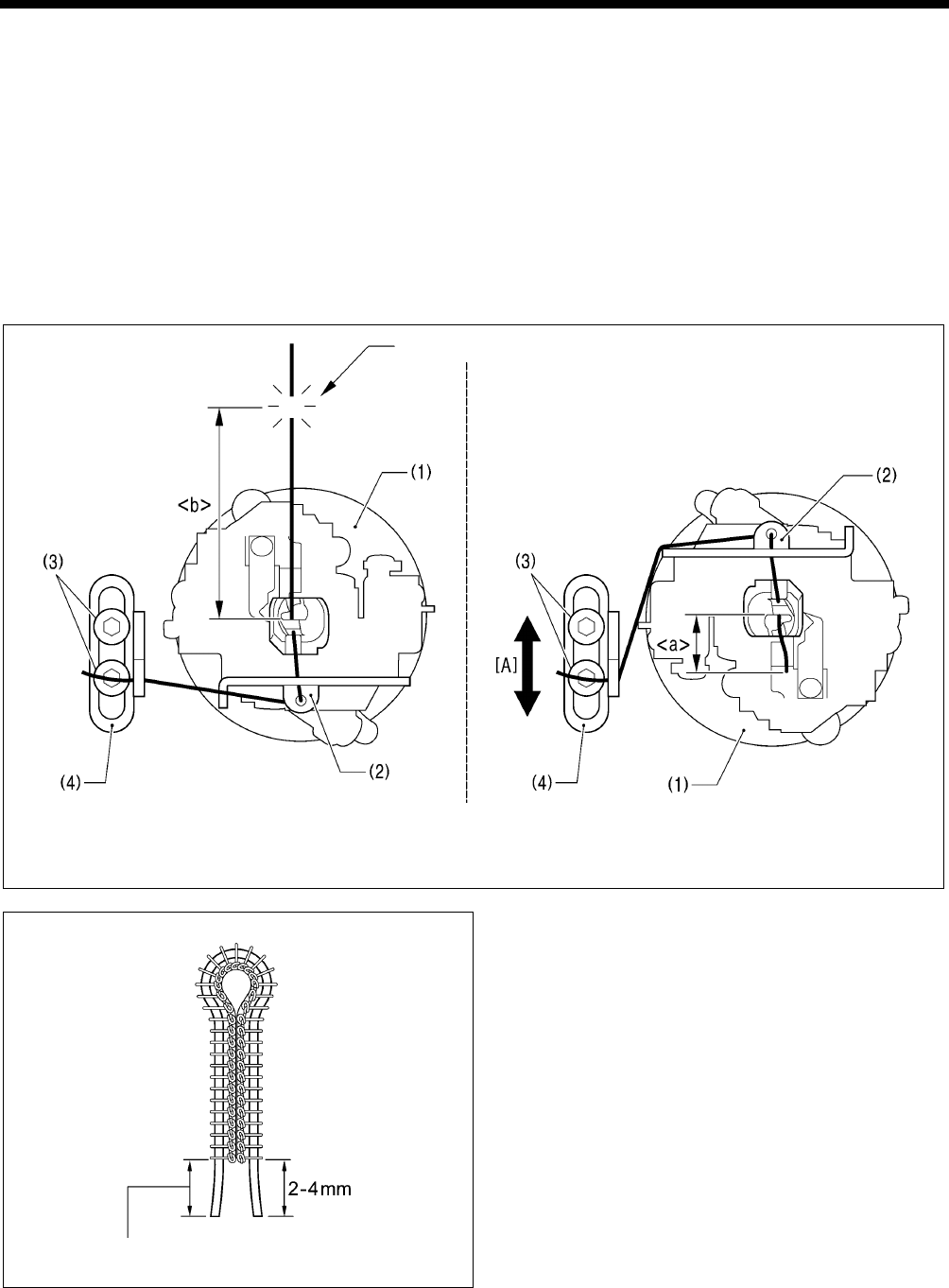
7. ADJUSTMENTS
RH-9820
179
0547B
7-27. Adjusting the gimp trailing length <-02 specifications only>
The gimp is pressed against the material by means of the twisting of the first 2 - 3 stitches at the sewing start, and is then pulled
out continuously. Because of this, if strong tension is applied to the gimp when the feed base is at the sewing position and the
gimp trailing length (<a> in the illustration below) becomes extremely short, the gimp may be pulled out of the stitches.
The gimp should be adjusted to as short a length as possible which will still allow the gimp to be securely wound around the
stitches at the sewing start and leave a length protruding from above the stitches.
NOTE: Principle of gimp pulling
When the looper base (1) turns back from 180 degrees to 0 degrees after the gimp has been trimmed, gimp thread guide
C-J (2) pulls the gimp to make it come out.
Adjustment of the gimp trailing length is necessary in the following cases.
• When the sewing length has been changed (the gimp is trimmed at the feed base home position, so the length of <b>
will change. As a result, the gimp trailing length <a> will also change.)
• When the type of gimp and the gimp tension have been changed (the gimp trailing length <a> will change.)
Gimp is trimmed
When looper base is turned 180 degrees When looper base has returned to 0 degrees
(Viewed from directly above)
<Adjustment method>
1. Loosen the screw (3).
2. Move gimp thread guide J (4) in the direction of the arrow
[A] to adjust so that 2 - 4 mm of the gimp protrudes from
the seam at the sewing start.
3. Once adjustment is complete, securely tighten the screw
(3).
The gimp trailing length at the sewing end is uniform because of
thread trimming.
0548B
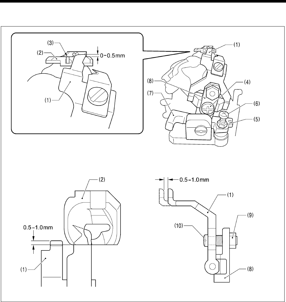
7. ADJUSTMENTS
RH-9820 180
7-28. Adjusting the position of the lower thread presser <-02 specifications only>
Adjust the lower thread presser (1) so that it securely holds the lower thread.
(Viewed from the front)
(Viewed from directly above) (Viewed from directly to the right)
1. Loosen the screw (4) and move the lower thread presser (1) up or down to adjust so that its top projects approximately 0.5
mm from the top of the thread groove (3) in the throat plate (2).
2. Check that the lower thread presser (1) does not cover the groove at the front of the throat plate (2).
* If the groove is covered, loosen the nut (5) and then turn the screw (6) to adjust.
3. Check that the front of the throat plate (2) and the lower thread presser (1) are overlapping by 0.5 - 1.0 mm after thread
trimmer lever bracket B (7) has operated.
* If adjustment is required, remove the lower thread presser base (8), loosen the nut (9), and then turn the screw (10) to
adjust.
4. Once adjustment is complete, tighten the nuts (5) and (9) that were loosened, and install the lower thread presser base (8).
0549B
0550B
0551B
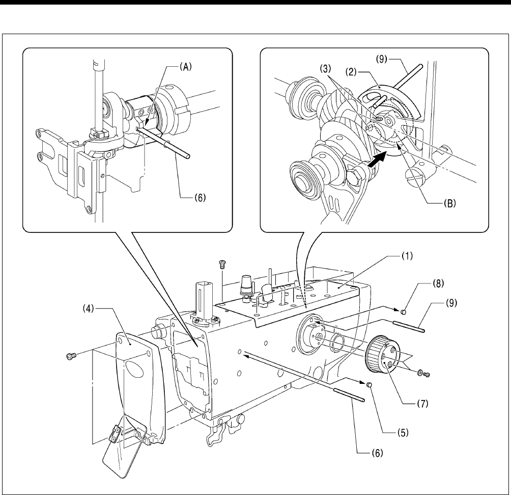
7. ADJUSTMENTS
RH-9820
181
7-29. Adjustment of the phase for the take-up roller cam
1. Remove the upper cover (1).
2. Loosen the two set screws (3) of the take-up roller cam (2).
3. Remove the face plate (4).
4. Set the sewing machine to the stopped position.
5. Remove the rubber cap (5) and then insert the accessory pin (6).
* Check that the pin (6) is inserted into the groove (A) in the upper shaft crank at this time so that the upper shaft is secured
and cannot be turned.
6. Remove the upper shaft pulley (7).
7. Remove the rubber cap (8), and then insert the accessory pin (9) into the hole in the take-up roller cam (2).
8. Push the take-up roller cam (2) against the edge of the bearing (B), and then tighten one of the set screws (3).
9. Pull out the pins (6) and (9) and then tighten the other set screw (3).
10. Once adjustment is complete, install the rubber cap (8), rubber cap (5), upper shaft pulley (7), face plate (4) and upper cover (1)
in that order.
0751B

7. ADJUSTMENTS
RH-9820 182
7-30. Adjusting the needle bar and looper base turning center
The turning center for the needle bar and the looper base is accurately adjusted at the time of shipment from the factory.
If the sewing machine has been disassembled (such as when replacing the needle bar gear block unit, needle bar or looper base),
adjust the position of needle bar bush U (2) so that the clearance <a> between the needle and the tip of eye looper (1) remains
uniform while the looper rotates through 360°.
NOTE:
Before adjusting the position of the needle bar bush U (2), check that there is no play in the needle bar gear block and the
looper base. If there is any play, adjust while referring to “6-2. Needle bar mechanism (1): Adjusting the pressure of the needle
bar gear block” and “6-8. Looper base mechanism: Looper base pressure adjustment”.
Needle
Eye looper(1)
When looper base is at 0° When looper base is at 180°
Index mark
When looper base is at 90° When looper base is at 270°
<Adjustment>
1. Loosen the two bolts (3), and then remove the needle bar guard (4).
2. Turn the upper shaft pulley until the tip of the eye looper (1) is aligned with the center of the needle.
3. Turn the looper base (5) by hand and check that the distance A between the tip of eye looper (1) and the needle when the looper
base (5) is turned to 0° is the same as the distance B when the looper base is turned to 180°.
4. If there is a large difference between distance A and distance B, loosen the three bolts (6) and move the needle bar (7) gently
forward or back to adjust the position of needle bar bush U (2). Tighten the bolts (6), and then repeat the check in step (3).
5. Turn the looper base (5) by hand and check that the distance C between the tip of eye looper (1) and the needle when the
looper base (5) is turned to 90° is the same as the distance D when the looper base is turned to 270°.
6. If there is a large difference between distance C and distance D, loosen the three bolts (6) and move the needle bar (7) gently to
the left or right to adjust the position of needle bar bush U (2). Tighten the bolts (6), and then repeat the check in step (5).
7. Carry out the check in step 3 once more.
NOTE:
• Once adjustment is finished, turn the upper shaft pulley and check that the needle bar moves gently up and down.
• If a sheet of paper is placed under the needle and the needle drop position is adjusted so that the needle makes a single hole in the
paper, the distance <a> between the needle and the tip of eye looper (1) will still not be uniform.
0753B0752B
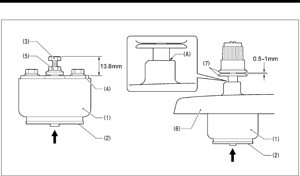
7. ADJUSTMENTS
RH-9820
183
7-31. Adjusting the upper thread loosening amount
1. With the plunger (2) of the upper thread tension release solenoid (1) pushed all the way in, loosen the nut (5) and turn the bolt
(3) to adjust so that the clearance between the end of the bolt (3) and the solenoid setting plate (4) is 13.8 mm.
2. With the upper thread tension release solenoid (1) installed to the upper cover (6), check that the opening amount for the
tension discs (7) is 0.5 - 1 mm when the plunger (2) is pushed all the way in.
* Section (A) should be sealed at this time.
0754B
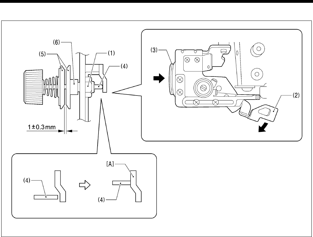
7. ADJUSTMENTS
RH-9820 184
7-32. Adjusting the lower thread loosening amount
1. Loosen the nut (1).
2. Turn the lower thread release plate (2) by hand or push the plunger (3) of the tension release solenoid from the back to turn the
lower thread release plate (2) until the tension release pin (4) is sitting on stepped part [A].
3. Turn the tension stud D (6) to adjust the height so that the opening amount for the tension discs (5) is 1 ± 0.3 mm at this time.
4. Tighten the nut (1).
0781B
7. ADJUSTMENTS
RH-9820
185
7-33. Adjusting the looper base home position
NOTE:
Before carrying out this adjustment, check that the adjustments in “6-9. Needle bar rocking mechanism: Belt tension adjustment
for driving looper belt” have been carried out correctly.
1. Remove the left and right work clamp plates (Z).
2. While holding down the and keys (1), push the
POWER switch at the ON side (2).
3. Press the start switch (3).
The motors will carry out home position detection, and then
the sewing machine will switch to home position adjustment
mode.
* At this time, “X” will appear in the display (A).
4. Press the or key (4) to change the display (A) to “θ”.
* When “θ” is displayed, the X and Y feed motors will be
turned off, so that the feed base can be moved by hand.
0749B
0763B
0972B
0819B
(A)
7. ADJUSTMENTS
RH-9820 186
5. Press the or key (1) to change the offset value (B).
The looper base (5) will move as the keys are pressed. Do
this until the looper base reference line (0°) <b> is aligned
with the bed reference line <a>.
* The setting range is -12.86 ° - +12.86° (in units of 0.64°).
6. Press the ENTER key (6).
The home position detection operation will be carried out,
and the offset value (B) will be saved.
NOTE:
If you continue to the next step without pressing the
ENTER key (6), the offset value will not be changed.
7. Check that the bed reference line <a> and the looper base
reference line (0°) <b> are aligned.
* If they are not aligned, repeat steps 5 and 6 until they
are aligned.
8. Press the TEST key (7).
Home position adjustment mode will end and the sewing
machine will return to home position standby.
1194B
0764B
0733B
(B)
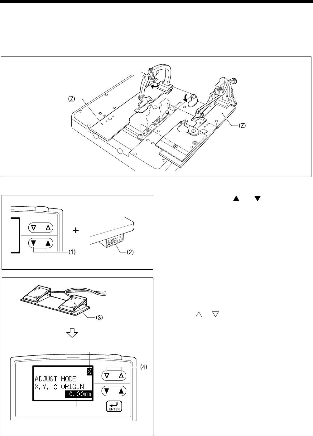
7. ADJUSTMENTS
RH-9820
187
7-34. Adjusting the feed base X home position and Y home position
NOTE:
* Before adjusting the X home position, check that the adjustment in “6-16. X feed mechanism: Standard installation position for
motor unit (idle gear adjustment)” has been carried out correctly.
* Before adjusting the Y home position, check that the adjustment in “6-7. Y feed mechanism: Standard installation of motor unit”
has been carried out correctly.
1. Remove the left and right work clamp plates (Z).
2. While holding down the and keys (1), push the
POWER switch at the ON side (2).
3. Press the start switch (3).
The motors will carry out home position detection, and then
the sewing machine will switch to home position adjustment
mode.
* At this time, “X” will appear in the display (A).
4. Press the or key (4) as necessary to change the
display (A) so that “Y” appears.
* “X” or “Y” should be displayed while this adjustment is
carried out.
[When “X” is displayed]
The motor (θ) for driving the looper base will be turned off,
so that the looper base and needle bar gear block can
be moved by hand.
[When “Y” is displayed]
The X-feed motor, Y-feed motor and motor (θ) for driving
the looper base will all be turned on, so that the looper
base and needle bar gear block cannot be moved by
hand.
0749B
0763B
0972B
0819B
(A)
(B)
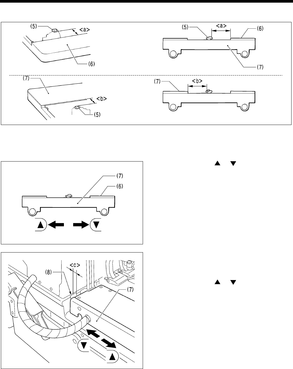
7. ADJUSTMENTS
RH-9820 188
5. [Adjusting the X home position]
(When the looper base is turned 0°)
(When the looper base is turned 180°)
Carry out the following adjustments so that the distances <a> (when the looper base is turned 0°) and <b> (when the looper
base is turned 180°) between the end of the projection on the throat plate (5) and the sides of feed base cover R (6) and feed
base cover L (7) on the feed base are equal.
5-1. Turn the looper base by hand and measure the distances <a> and <b>.
5-2. When you press the or key (1) to change the
offset value (B), the feed base (7) will move as the keys
are pressed. Repeat this step until distances <a> and <b>
are equal.
* The setting range is -2.00 - +2.00 mm (in units of 0.05
mm).
[Adjusting the Y home position]
Carry out the following adjustments so that the distance <c>
between the rear of the feed base (7) and the hollow in the bed
(8) is 18 ± 0.2 mm.
5-3. When you press the or key (1) to change the
offset value (B), the feed base (7) will move as the keys
are pressed.
* The setting range is -2.00 - +2.00 mm (in units of 0.05
mm).
(Continued on next page)
0765B
0766B
0818B
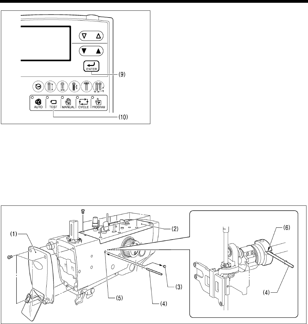
7. ADJUSTMENTS
RH-9820
189
6. Press the ENTER key (9).
The home position detection operation will be carried out,
and the offset value (B) will be saved.
NOTE:
If you continue to the next step without pressing the
ENTER key (9), the offset value will not be changed.
7. Check the results of the adjustments.
* If the adjustments are not correct, repeat steps 5 and 6.
* To continue with another adjustment, repeat the
adjustment procedure from step 4.
8. Press the TEST key (10).
Home position adjustment mode will end and the sewing
machine will return to home position standby.
7-35. Adjusting the needle up signal home position for the upper shaft and
upper shaft motor
NOTE:
• Before carrying out this adjustment, check that the adjustments in “6-18. Upper shaft motor mechanism: Standard installation of
upper shaft motor unit and belt tension adjustment)” and “6-10. Lower shaft mechanism: Belt (upper shaft - lower shaft)
installation and belt tension adjustment” have been carried out correctly.
• After carrying out this adjustment, be sure to carry out the procedure in “7-36. Adjusting the upper shaft stop position”.
1. Remove the face plate (1) and the upper cover (2).
2. Remove the rubber cap (3).
3. Insert the accessory pin (4) into the groove (6) in the balance collar from the hole (5) in the arm to stop the upper shaft from
turning. (Upper shaft: 22.5° position)
0768B
0767B
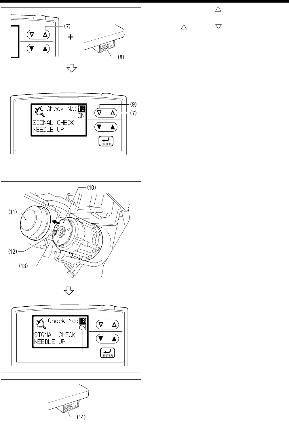
7. ADJUSTMENTS
RH-9820 190
4. While holding down the key (7), push the POWER
switch at the ON side (8).
The mode will switch to input checking mode.
5. Press the key (7) or key (9) to set the checking
signal (A) to “18 (needle up signal)”.
6. Tilt back the machine head and remove the motor cover (11)
from the upper shaft motor (10).
7. Loosen the bolt (12) for the needle up magnet of the motor
by 90° only.
NOTE:
Do not loosen the screw by more than 90°. If it is
loosened too much, the parts may touch the P. C. board
and damage may result.
8. Move the position of the slot (13) to the point where the
panel display (B) switches from “ON” to “OFF”, and tighten
the bolt (12) at that point.
9. Press the POWER switch at the OFF side (14) to turn off the
power.
(B)
0771B
(A)
0769B
0784B
0770B
0784B
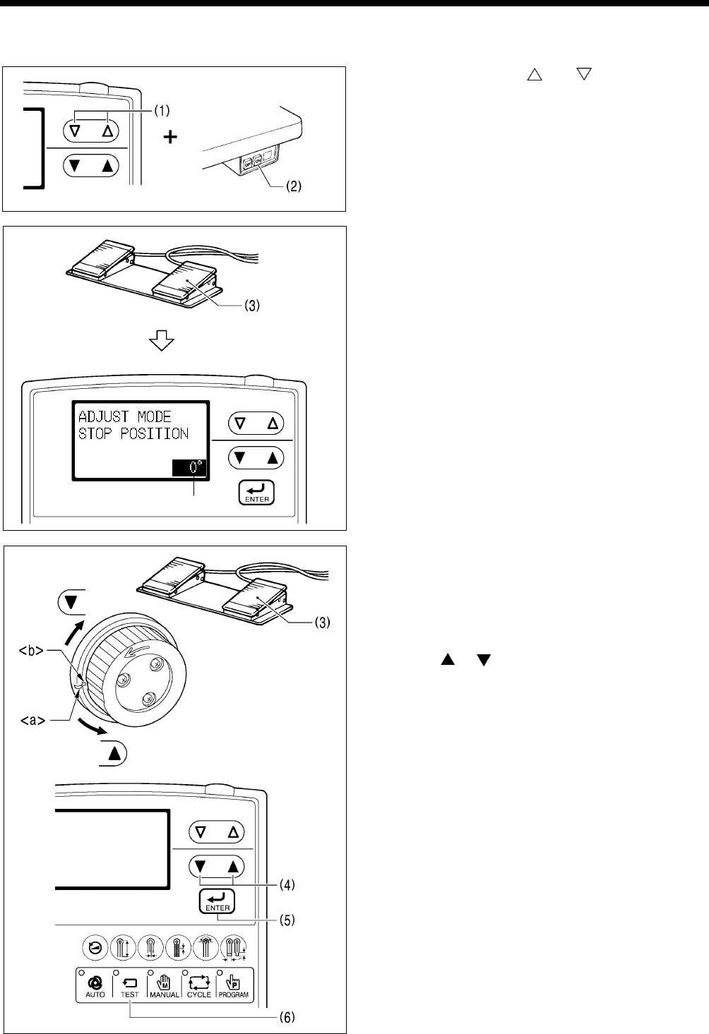
7. ADJUSTMENTS
RH-9820
191
7-36. Adjusting the upper shaft stop position
Adjust the stop position so that upper thread loops are maintained when the upper thread is trimmed.
1. While holding down the and keys (1), push the
POWER switch at the ON side (2).
2. Press the start switch (3).
The motors will carry out home position detection, and then
the work clamp will be lowered to the ready position and the
sewing machine will switch to upper shaft stop position
adjustment mode.
* In upper shaft stop position adjustment mode, the offset
value (A) is displayed.
3. Press the start switch (3) again until the upper shaft begins
to move.
4. After the upper shaft stops, check that the arm reference line
<a> and the upper shaft pulley reference line <b> are
aligned.
[If they are not aligned]
Press the or key (4) to change the offset value (A),
and then repeat step 3.
* The setting range is -5 ° - +10° (in units of 1°).
[If they are aligned]
Continue to the next step.
5. Press the ENTER key (5).
The offset value will be stored.
NOTE:
If you continue to the next step without pressing the
ENTER key (5), the offset value will not be changed.
6. Press the TEST key (6).
Upper shaft stop position adjustment mode will end and the
sewing machine will return to home position standby.
0973B
(A)
0974B
0820B
0772B
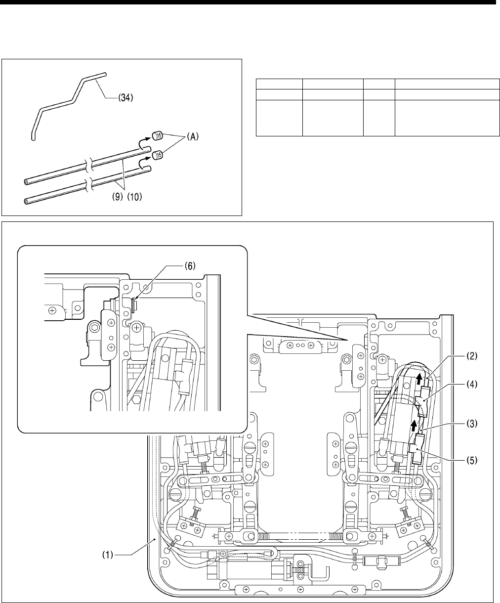
7. ADJUSTMENTS
RH-9820 192
7-37. Installing (replacing) the sub clamp on the left side
If necessary, the sub clamp can be removed from the right side and can be installed on the left side instead. In this case, the
following optional parts are required.
To install the sub clamp on the left side, first have the following
option parts ready.
Ref. No. Code Qty. Part name
(34) SA7152001 1 Sub clamp wrist L
(9) (10) SA5683001 2 Air hose (outer dia. 4
mm, inner dia. 2.5 mm,
length 750 mm)
* Be sure to remove the stickers (A) before using the air
hoses (9) and (10).
(Top)
1. Stop the air and then bleed the air. (Refer to “3-16. Adjusting the air pressure” in the instruction manual.)
2. Remove the feed base unit (1) from the bed. (Refer to “5-3. Feed mechanism”.)
3. Disconnect the air tubes (2) and (3) from the joints (4) and (5).
4. Remove retaining ring C (6).
(Continued on next page)
1168B
1167B
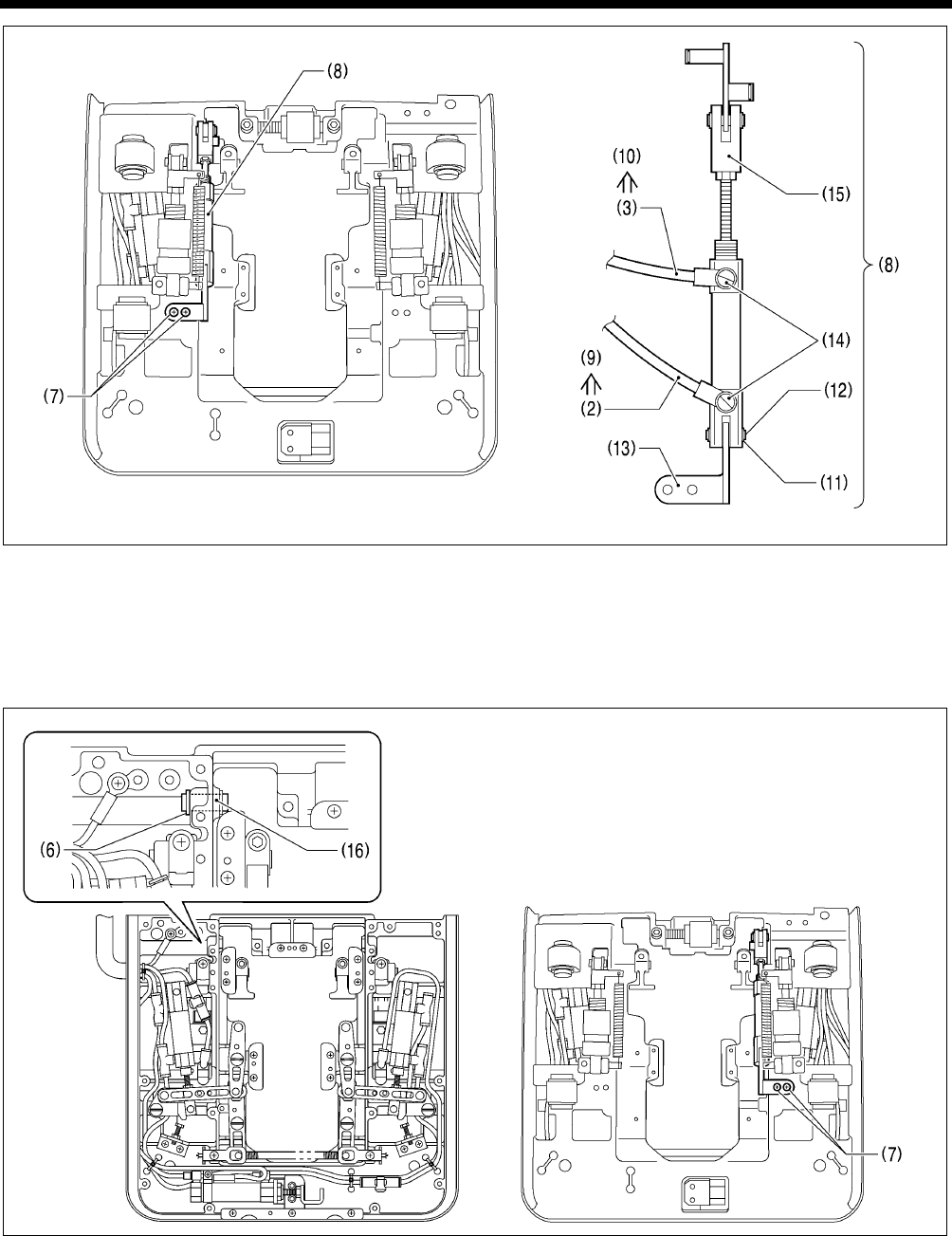
7. ADJUSTMENTS
RH-9820
193
(Bottom)
(Viewed from above)
5. Remove the two screws (7), and then remove the sub clamp cylinder assembly (8).
6. Replace the air hoses (2) and (3) with the optional air hoses (9) and (10).
7. Remove retaining ring C (11) and pull out the shaft (12).
8. Insert the shaft (12) into the sub clamp S holder (13) in the direction shown in the illustration, and then install retaining ring C
(11).
9. Set the joint (14) and the cylinder rod (15) so that they are facing as shown in the illustration.
(Top) (Bottom)
10. Insert the shaft (16) of the sub clamp connecting rod into the hole in the feed base, and then install retaining ring C (6).
11. Tighten the two screws (7).
1169B
1170B
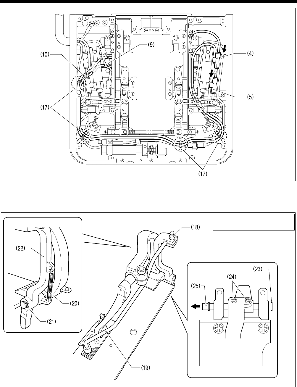
7. ADJUSTMENTS
RH-9820 194
(Top)
12. Route the tubes as shown in the illustration, and then connect the air hose (9) to the joint (4) and the air hose (10) to the joint
(5).
13. Secure the air hoses (9) and (10) in four places using the four bead bands (17) as shown in the illustration.
14. Loosen the socket bolt (18), and then remove the sub clamp wrist (19).
15. Remove the spring (20).
16. Remove retaining ring C (21), and then remove the sub clamp arm (22).
17. Remove retaining ring C (23), loosen the two set screws (24), and then remove clamp support shaft J (25) in the direction of
the arrow.
(Continued on next page)
1171B
1172B
(Viewed from the underside)
Work clamp plate R assembly
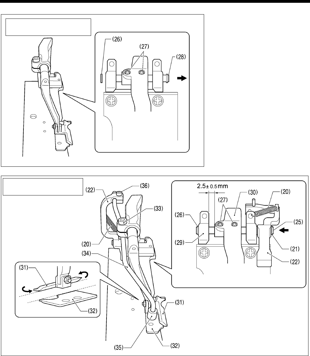
7. ADJUSTMENTS
RH-9820
195
18. Remove retaining ring C (26), loosen
the two set screws (27), and then
remove the clamp support shaft (28)
in the direction of the arrow.
19. Insert clamp support shaft J (25) in the direction of the arrow, and then install retaining ring C (26).
20. Place the sub clamp arm (22) onto clamp support shaft J (25) as shown in the illustration, and then install retaining ring C (21).
21. Tighten the two set screws (27) so that the clearance between the clamp shaft holder (29) and clamp lever L (30) is 2.5 ± 0.5
mm.
* Check that the sides of work clamp L (31) and needle plate L (32) are aligned at this time. If they are not aligned, loosen
the socket bolt (33) and adjust.
22. Install the button clamp (35) to the optional sub clamp wrist L (34).
23. Install sub clamp wrist L (34) to the sub clamp arm (22), and then secure it by tightening the socket bolt (36).
(Refer to “7-26-4. Adjusting the position of the sub clamp”.)
24. Install the spring (20) to the sub clamp arm (22) and the clamp shaft holder (29).
Work clamp plate L assembly
1173B
1174B
(Viewed from the underside)
Work clamp plate L assembly
(Viewed from the underside)
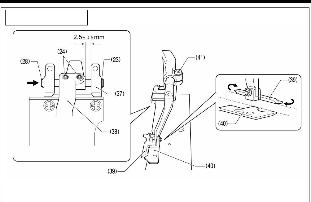
7. ADJUSTMENTS
RH-9820 196
Work clamp plate R assembly
25. Insert the clamp support shaft (28) in the direction of the arrow, and then install retaining ring C (23).
26. Tighten the two set screws (24) so that the clearance between the clamp shaft holder (37) and clamp lever R (38) is 2.5 ± 0.5
mm.
* Check that the sides of work clamp R (39) and needle plate R (40) are aligned at this time. If they are not aligned, loosen the
socket bolt (41) and adjust.
1175B
(Viewed from the underside)

8. ELECTRICAL MECHANISM
197 RH-9820
8. ELECTRICAL MECHANISM
DANGER
Wait at least 5 minutes after turning off the power switch and disconnecting the power cord from the wall outlet
before opening the cover of the control box. Touching areas where high voltages are present can result in severe
injury.
8-1. Precautions while carrying out adjustments
Electric shocks
High voltages can remain in large-capacity capacitors for up to 5 minutes in some circumstances, even when the power has
been turned off. Accordingly, wait at least 5 minutes after turning off the power before carrying out the following operations.
• Opening and closing the control box
• Replacing fuses
• Inserting and disconnecting connectors
• Measuring resistance values
• Any other tasks that may involve touching components inside the control box
Some inspection items require the control box to be open when the power is turned on and voltages are measured.
At such times, be extremely careful never to touch anywhere other than the specified locations. In addition, note that high
voltages may remain for up to 5 minutes after the power is turned off.
Injury
Be careful not to touch metallic objects such as the heat sink and cover when connecting and disconnecting connectors and
making measurements.
Be sure to note the following cautions when opening the control box to carry out inspections and adjustments.
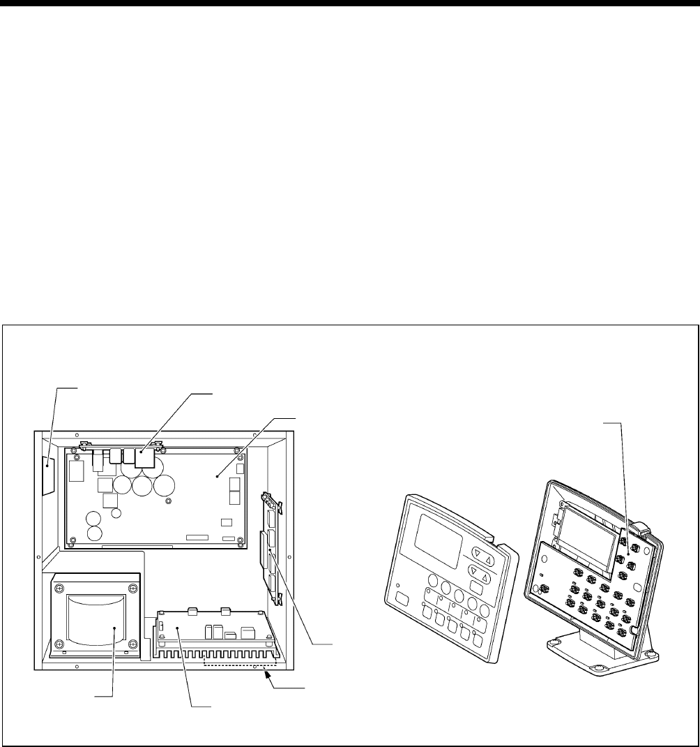
8. ELECTRICAL MECHANISM
198
RH-9820
8-2. Inside the control box and operation panel structure
Main P.C. board
Secured to the side. This is the P.C. board that controls sewing machine operation.
PMD P.C. board
Secured to the base plate. This P.C. board drives the pulse motors and solenoids.
Power supply motor P.C. board
Secured to the rear. This P.C. board generates the voltages that are required for control, and drives the upper shaft motor.
There are 8 fuses on this P.C. board.
Filters (3 places)
The filters at the air intake slots in the cover and control box (2 places) should be cleaned about once a month.
Conversion transformer (Two types are used depending on the power supply voltage specifications.)
This breaks down the power supply voltage into the voltages that are required for control operations.
NF P.C. board
This eliminates the electrical interference that is generated by the power supply line.
Panel P.C. board
Secured to the inside of the operation panel. This P.C. board is used for displaying the sewing machine status and for input
operations.
Control box Operation panel
Filter NF P.C. board
Conversion
transformer PMD P.C. board
1199B 0692B
Panel P.C. board
Power supply
motor P.C. board
Main P.C. board
Filter
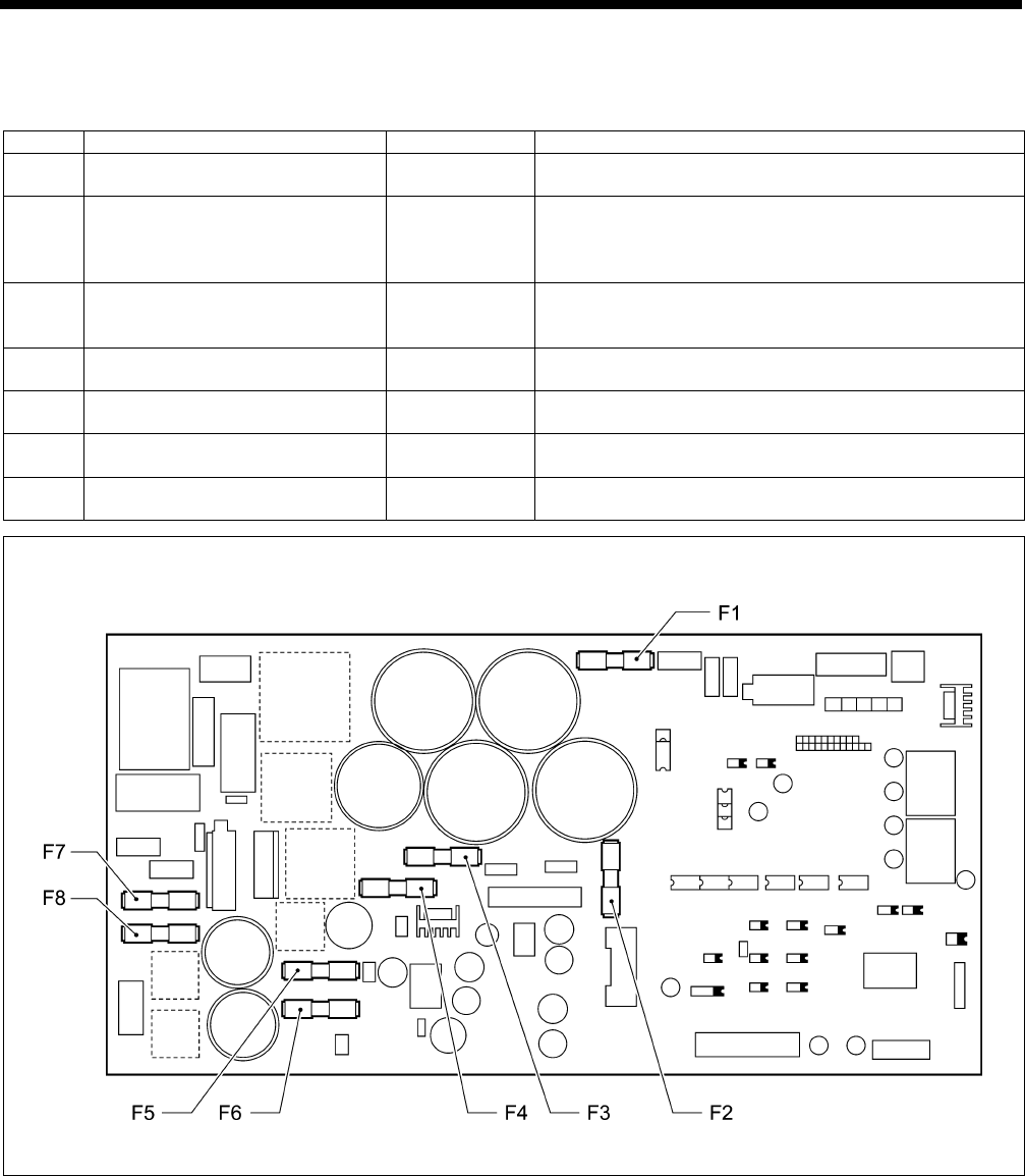
8. ELECTRICAL MECHANISM
199 RH-9820
8-3. Description of fuses
When replacing the fuses, be sure to use the fuses specified below.
If the components on the P.C. boards are damaged, the fuses may blow again soon even after they have been replaced.
No. Part name Parts code Symptom when fuse blows
F1 Fuse 15AFB
(Glass tube fuse 15A-250V) SA3794-001 Sewing machine motor does not operate and [E130] is
displayed.
F2 Fuse 6AFB
(Glass tube fuse 6A-250V) SA3759-001
Feed mechanism does not operate and [E201] or
[E211] is displayed.
θ pulse motor does not operate and [E220] is
displayed.
F3 Fuse 6AFB
(Glass tube fuse 6A-250V) SA3759-001
Thread trimming solenoid or digital tension/tension
release solenoid does not operate, and thread
trimming or thread tightening problems occur.
F4 Fuse 3AFB
(Glass tube fuse 3A-250V) 616167-001 Communication problem with PMD P.C. board and
[E403] is displayed.
F5 Fuse 3AFB
(Glass tube fuse 3A-250V) 616167-001 Power indicator does not illuminate and nothing
operates.
F6 Fuse 3AFB
(Glass tube fuse 3A-250V) 616167-001 DC fan motor does not operate and [E740] is
displayed.
F7
F8
Fuse 15AFB
(Glass tube fuse 15A-250V) SA3794-001 Power indicator does not illuminate and nothing
operates.
Power supply motor P.C. board
4590Q
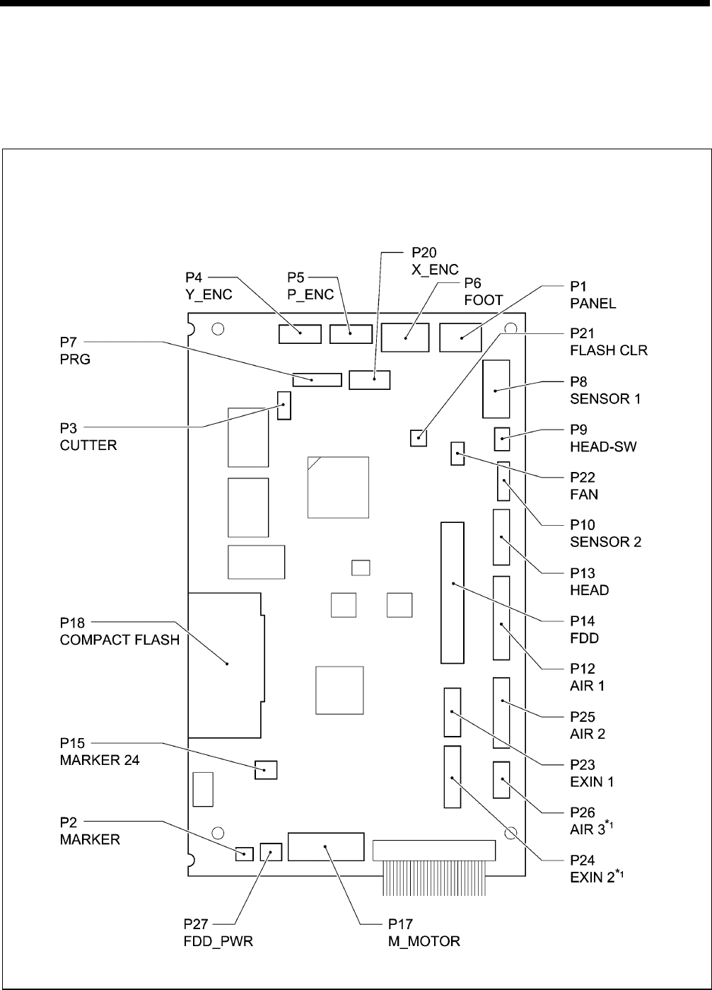
8. ELECTRICAL MECHANISM
200
RH-9820
8-4. Description of connectors
A large number of problems are often caused by connectors that are not inserted correctly or which are contacting poorly.
As a result, check that all connectors are inserted correctly and that the pins and wires are crimped properly before carrying
out problem diagnosis.
8-4-1. Connector positions
Main P.C. board
*1 This is a spare signal for special orders.
1200B
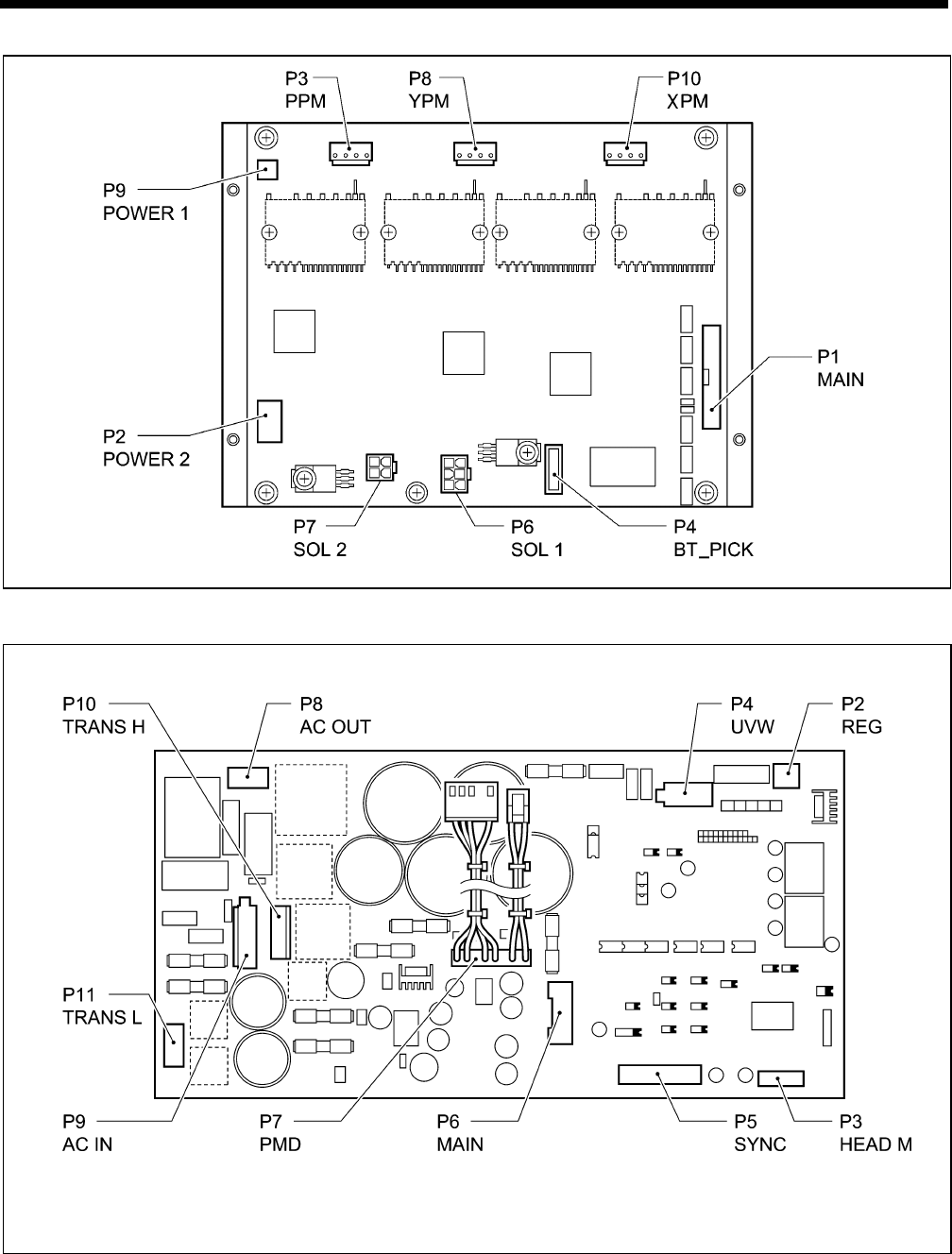
8. ELECTRICAL MECHANISM
201 RH-9820
PMD P.C. board
Power supply motor P.C. board
0693B
4593Q
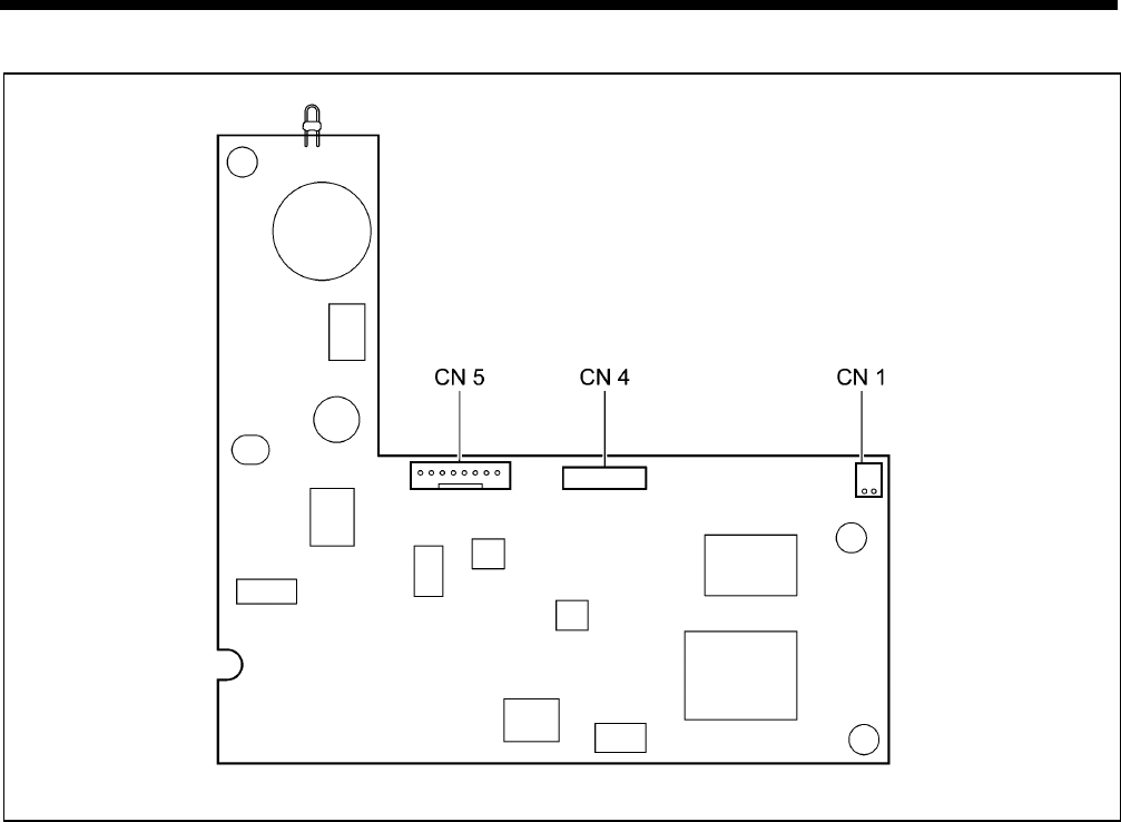
8. ELECTRICAL MECHANISM
202
RH-9820
Panel P.C. board
0694B
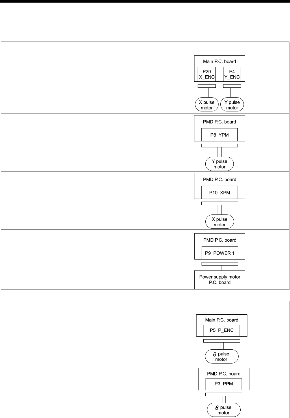
8. ELECTRICAL MECHANISM
203 RH-9820
8-4-2. Symptoms when there are poor connections
This divides the functions of the connectors into five sections, but some connectors have more than one function, so be sure
to refer to the trouble symptoms in other sections too.
Feed mechanism
Trouble symptom Connector No. and position
• The feed mechanism operates briefly but does not detect
the home position correctly.
• [E200] or [E210] is displayed.
• Problems with feed mechanism moving forward and back.
• [E210] or [E211] is displayed.
• Problems with feed mechanism moving to the left and right.
• [E200] or [E201] is displayed.
• Feed motor does not operate.
• [E200] is displayed.
θ pulse motor mechanism
Trouble symptom Connector No. and position
• The θ pulse motor operates, but the home position is not
detected correctly.
• [E220] is displayed.
• The θ pulse motor does not operate.
• [E220] or [E221] is displayed.
5241Q
4708Q
4709Q
4710Q
0755B
0756B
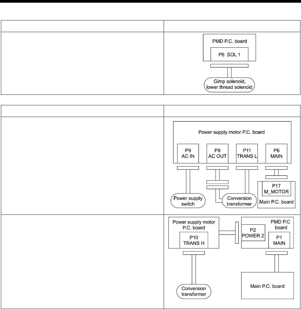
8. ELECTRICAL MECHANISM
204
RH-9820
Thread trimming mechanism
Trouble symptom Connector No. and position
• Gimp solenoid and lower thread solenoid do not operate.
(No error displayed)
Sewing operations
Trouble symptom Connector No. and position
• Power indicator does not illuminate and sewing machine
does not operate.
• Operation is unstable.
• [E403] is displayed when the power is turned on and the
sewing machine does not start.
5244Q
4717Q
0757B
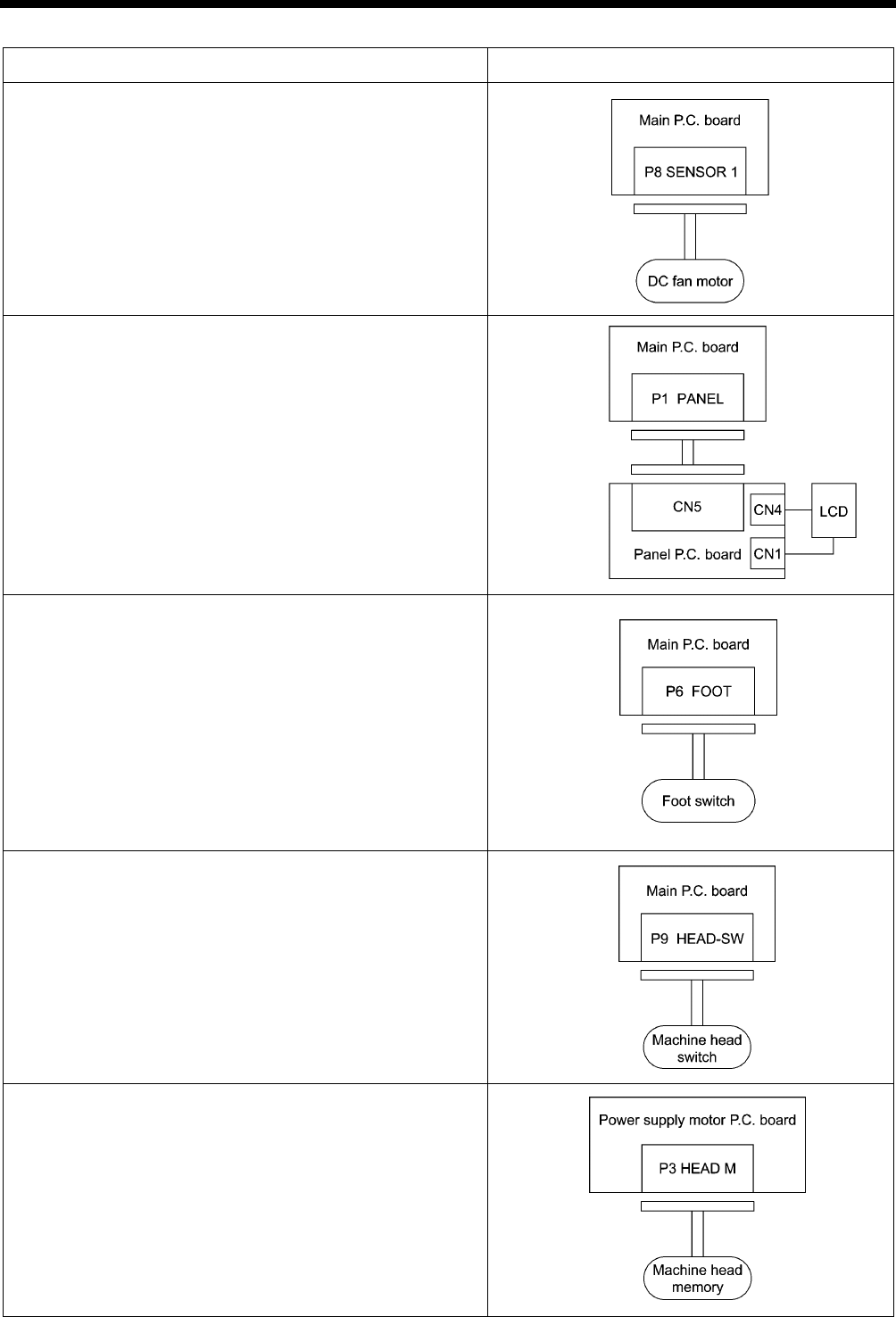
8. ELECTRICAL MECHANISM
205 RH-9820
Other
Trouble symptom Connector No. and position
• DC fan motor does not operate.
• [E740] is displayed.
• Operation panel display is incorrect.
• Power indicator does not illuminate.
• Operation panel keys do not work.
• Backlight does not illuminate.
• Sewing machine does not start when foot switch is
depressed.
[Treadle]
Work clamp drops when depressed to the 1st step
Sewing machine starts when depressed to the 2nd step
[2 pedal]
Work clamp drops when work clamp switch (left) is depressed
Sewing machine starts when start switch (right) is depressed
• After the power is turned on, [E055] is displayed.
• After the power is turned on, [E450] is displayed.
5247Q
5248Q
5249Q
0758B
0759B

8. ELECTRICAL MECHANISM
206
RH-9820
8-5. Troubleshooting
8-5-1. Troubleshooting procedure
Carry out troubleshooting by following the procedure given below.
1 Checking connectors With the power turned off, check that all connectors are securely inserted while
referring to “8-4. Description of connectors”.
2 Diagnosis flowchart Carry out diagnosis while following the steps in “8-5-2. Diagnosis flowchart” on the next
page, and if a problem # is reached, continue to the next procedure.
3 Remedy Refer to “8-5-3. Remedy” for the item that corresponds to the problem #. Carry out the
inspections for the problems in the order of the numbers in the “Cause” column.
NOTE:
When replacing the fuses, be sure to use a fuse with the same material and rating.
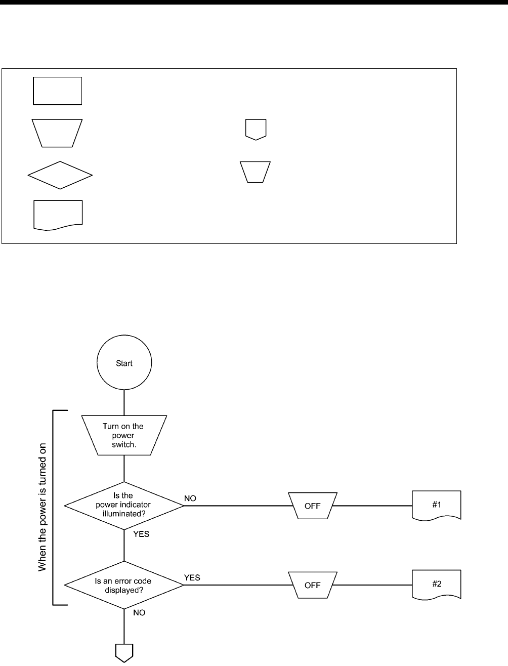
8. ELECTRICAL MECHANISM
207 RH-9820
8-5-2. Diagnosis flowchart
Description of symbols
Setting and status
Switch operation
Continued on previous/next page
Judgment
OFF Power switch OFF
“Problem” symbol in the “8-5-3. Remedy” lists
0760B
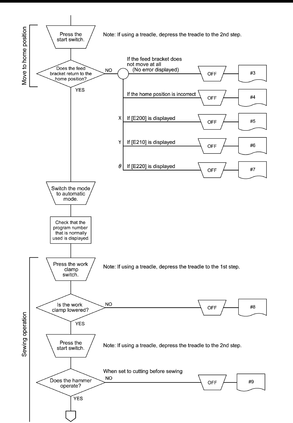
8. ELECTRICAL MECHANISM
208
RH-9820
0761B
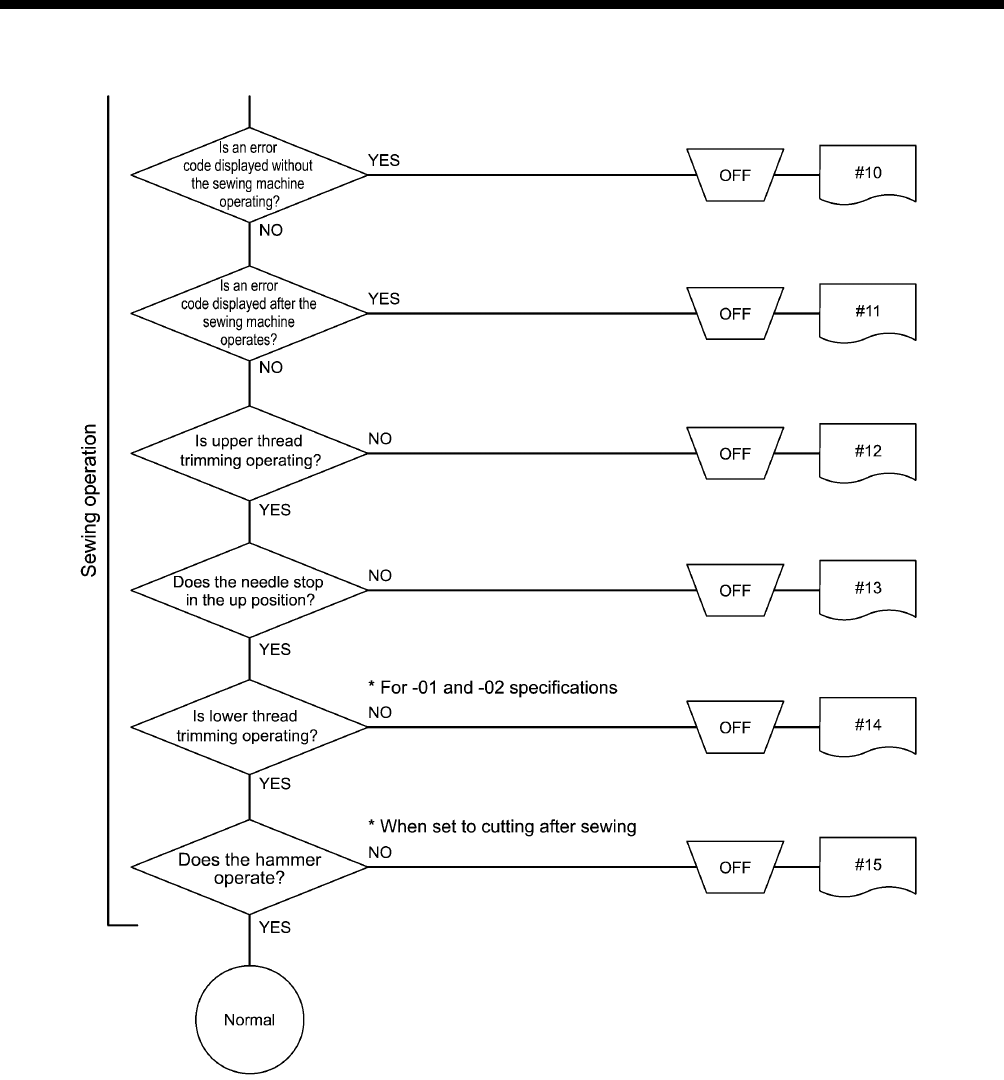
8. ELECTRICAL MECHANISM
209 RH-9820
0762B
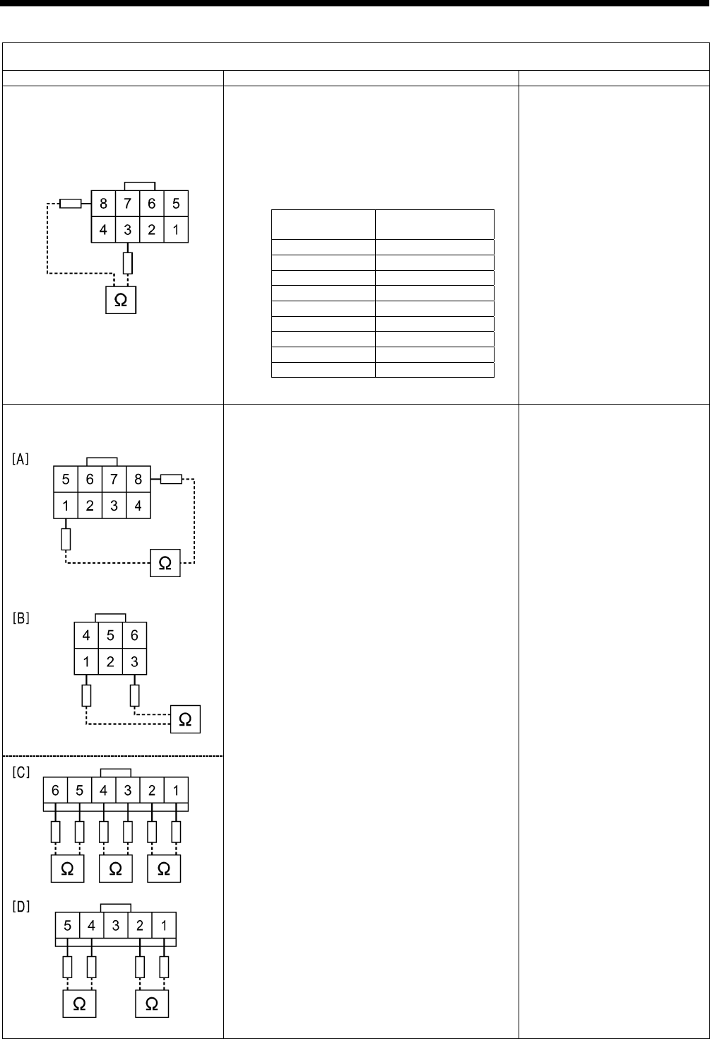
8. ELECTRICAL MECHANISM
210
RH-9820
8-5-3. Remedy
Problem #1 The power indicator does not illuminate when the power is turned on.
Cause Inspection/Remedy/Adjustment Replacement if a malfunction
1. Malfunction of voltage select
harness ***
For 200V specifications
a. Check if there is a broken wire in the voltage
select harness.
b. Disconnect the connector at the transformer
side, turn on the power and then measure the
voltage at the cord.
(The wiring position may vary depending on
the voltage specifications.)
OK if same as wall outlet voltage
Voltage select harness ***
(*** indicates voltage
specifications)
2. Malfunction of transformer
100V, 200V, 220V specifications
380V, 400V specifications
• For 100V, 200V, 220V specifications
1) OK if there is continuity between pins
1-8, 2-8, 3-8, 4-8, 5-8 and 6-8 of the
8-pin connector coming out from the
transformer. [Fig. A]
2) OK if there is continuity between pins
1-2, 3-4 and 5-6 of the 6-pin connector
coming out from the transformer.
[Fig. C]
3) OK if there is continuity between pins
1-2 and 4-5 of the 5-pin connector
coming out from the transformer.
[Fig. D]
• For 380V, 400V specifications
1) OK if there is continuity between pins
1-3, 2-3, 3-4 and 3-6 of the 6-pin
connector coming out from the
transformer.
[Fig. B]
2) OK if there is continuity between pins
1-2, 3-4 and 5-6 of the 6-pin connector
coming out from the transformer.
[Fig. C]
3) OK if there is continuity between pins
1-2 and 4-5 of the 5-pin connector
coming out from the transformer.
[Fig. D]
Transformer
Voltage
specifications Pin No.
100V 6-8
110V 5-8
120V 4-8
200V 3-8
220V 2-8
240V 2-7
H220V 3-6
380V 2-3
400V 1-3
4876Q
4879Q
4877Q
4878Q
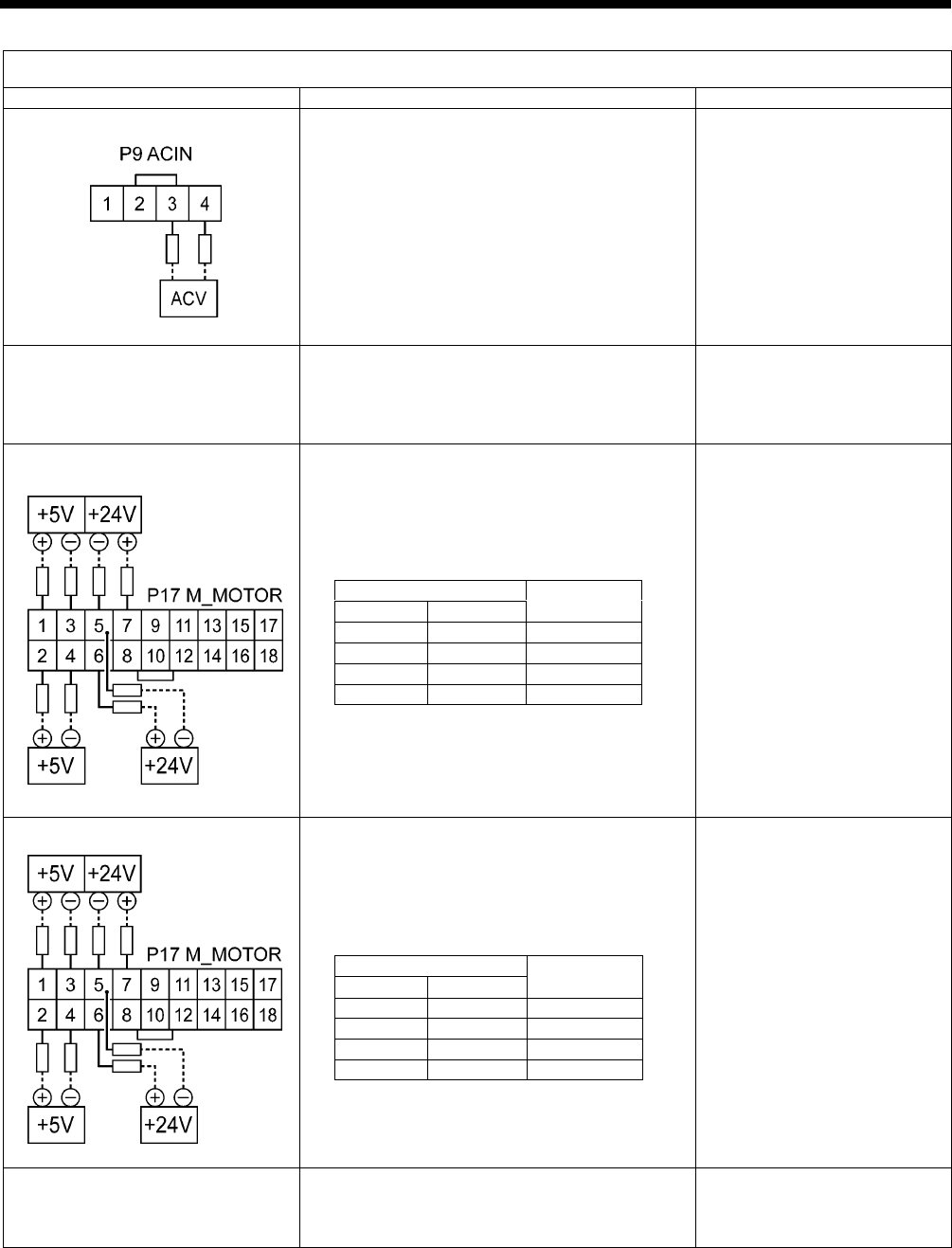
8. ELECTRICAL MECHANISM
211 RH-9820
Problem #1 The power indicator does not illuminate when the power is turned on.
Cause Inspection/Remedy/Adjustment Replacement if a malfunction
3. Malfunction of power cord Disconnect connector P9 (ACIN) on the power
supply motor P.C. board from the circuit board,
turn on the power, and then measure the voltage
between pins 3-4 of the cord-side connector.
OK if same as wall outlet voltage
After inspecting, turn off the power and insert
connector P9.
4. Blown fuse Remove fuses F7 and F8 and check the
continuity.
OK if continuity
(If there is no continuity, replace the fuse and
then carry out the inspections in 5. )
Glass tube fuse
15A-250V
5. Malfunction of power supply
motor P.C. board
Disconnect connector P17 (M-MOTOR) of the
main P.C. board, turn on the power, and then
measure the voltages between the pins at the
cord-side connector.
OK if the voltages are as shown in the table
below.
After measuring, turn off the power, wait 5
minutes or more and then insert P14.
Power supply motor P.C.
board
6. Malfunction of main P.C. board With connector P17 (M-MOTOR) inserted into
the main P.C. board, turn on the power and then
measure the voltages between the pins at the
cord-side connector.
OK if the voltages are as shown in the table
below.
After measuring, turn off the power.
Main P.C. board
7. Malfunction of panel P.C. board Check that connector P1 (PANEL) is inserted
into the main P.C. board, and that connector
CN5 (MAIN) is inserted into the panel P.C.
board.
Panel P.C. board
Panel harness
Pin Nos.
+ side
−
side
Normal
voltage
1 3 +5V
2 4 +5V
6 5 +24V
7 5 +24V
Pin Nos.
+ side
−
side
Normal
voltage
1 3 +5V
2 4 +5V
6 5 +24V
7 5 +24V
4880Q
5085Q
5085Q

8. ELECTRICAL MECHANISM
212
RH-9820
Problem #2 When the power is turned on, an error code is displayed.
Cause Inspection/Remedy/Adjustment Replacement if a malfunction
1. If [E025] or [E035] is displayed,
the foot switch is still depressed.
1) Check if the foot switch is still depressed.
2) Check that the setting for memory switch No.
050 is correct while referring to “2-3. Memory
switch setting method (Advanced)”.
3) Check if there is a harness short-circuit.
4) Check that connector P6 (FOOT) is inserted
into the main P.C. board.
5) Check the switch input while referring to “2-6.
Input checking method”.
Treadle unit
2-pedal foot switch
2. If [E055] is displayed, there is a
malfunction of the machine head
safety switch.
1) Check that the machine head safety switch is
OFF.
2) Check that connector P9 (HEAD-SW) is
inserted into the main P.C. board.
3) Check if there is a harness short-circuit.
4) Check the machine head safety switch input
while referring to “2-6. Input checking
method”.
Machine head safety switch
3. If [E065] is displayed, one of the
keys on the operation panel is
still depressed.
1) Check that connector P1 (PANEL) is
inserted into the main P.C. board, and that
connector CN5 (MAIN) is inserted into the
panel P.C. board.
2) Check the key input while referring to “2-6.
Input checking method”.
Panel P.C. board
Panel harness
4. If [E110] is displayed, there is a
malfunction of the needle up
signal.
1) Turn the upper shaft pulley to move the
needle bar to the needle up stop position.
2) Check that connector P5 (SYNC) is
connected to the power supply motor P.C.
board and that the synchronizer is
connected.
3) Check the zigzag sensor and needle up
signal input while referring to “2-6. Input
checking method”.
5. If [E403] is displayed, there is a
poor connection between the
main P.C. board and the PMD
P.C. board.
1) Check that connector P1 (MAIN) is inserted
into the PMD P.C. board.
2) Check if there is a harness short-circuit.
Main P.C. board
PMD P.C. board
6. If [E401] is displayed, there is a
poor connection between the
main P.C. board and the power
supply motor P.C. board.
1) Check that connector P17 (M-MOTOR) is
inserted into the main P.C. board, and that
connector P6 (MAIN) is inserted into the
power supply motor P.C. board.
2) Check if there is a harness short-circuit.
Harness
Power supply motor P.C.
board
Main P.C. board
7. If [E450] is displayed, the
machine head memory cannot
be verified.
1) Check that connector P3 (HEAD-M) is
inserted into the power supply motor P.C.
board.
2) Check if there is a harness short-circuit.
Machine head memory
8. If [E700] is displayed, there is
an abnormal rise in the power
supply voltage.
1) Check that the power supply voltage at the
wall outlet is within the range of the
specification voltage +/- 10%.
2) Refer to check items #1-2 and #1-3.
3) Check the power supply voltage while
referring to “2-6. Input checking method”.
9. If [E705] is displayed, there is
an abnormal drop in the power
supply voltage.
1) Check that the power supply voltage at the
wall outlet is within the range of the
specification voltage +/- 10%.
2) Refer to check items #1-2 and #1-3.
3) Check the power supply voltage while
referring to “2-6. Input checking method”.
10. If [E740] is displayed, there is a
malfunction of the cooling fan.
1) Check if there are any thread scraps blocking
the cooling fan.
2) Check that connector P8 (SENSOR1) is
inserted into the main P.C. board.
3) Check the fan signal input while referring to
“2-6. Input checking method”.
Fan motor assembly
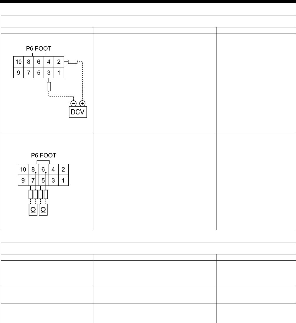
8. ELECTRICAL MECHANISM
213 RH-9820
Problem #3 Feed base does not move at all when the start switch is depressed.
Cause Inspection/Remedy/Adjustment Replacement if a malfunction
1. Malfunction of treadle unit
With connector P6 (FOOT) inserted into the main
P.C. board, turn on the power and then measure
the voltages between pins 2-3 at the cord-side
connector. (No. 2 +, No. 3 −)
OK if the voltage is approximately 2 V at neutral
and approximately 4 V when the foot switch is
depressed as far as it will go.
Treadle unit
2. Malfunction of 2-pedal foot
switch
Malfunction of hand start switch
Disconnect connector P6 (FOOT) from the main
P.C. board, and check the continuity between
pins 5-6 and 7-8 at the cord-side connector.
OK if normally ∞ Ω, and 0 Ω when the foot switch
is depressed.
Foot switch
Foot switch cord assembly
Hand start switch
Problem #4 Feed base home position is shifted.
Cause Inspection/Remedy/Adjustment Replacement if a malfunction
Incorrect home position adjustment Switch to home position adjustment mode and
adjust the position of the feed base while
referring to “7-34. Adjusting the feed base X
home position and Y home position”.
Sewing machine specifications and
memory switch settings do not
match.
Check that the settings for memory switch No.
850 and No. 851 are correct while referring to
“ 2-3. Memory switch setting method (Advanced)”.
Malfunction of encoder Check the mechanisms for the X axis, Y axis and
θ axis home position sensors while referring to
“2-6. Input checking method”.
Pulse motor X assembly
Pulse motor Y assembly
Pulse motor θ assembly
5086Q
1201B
Work
clamp
Start
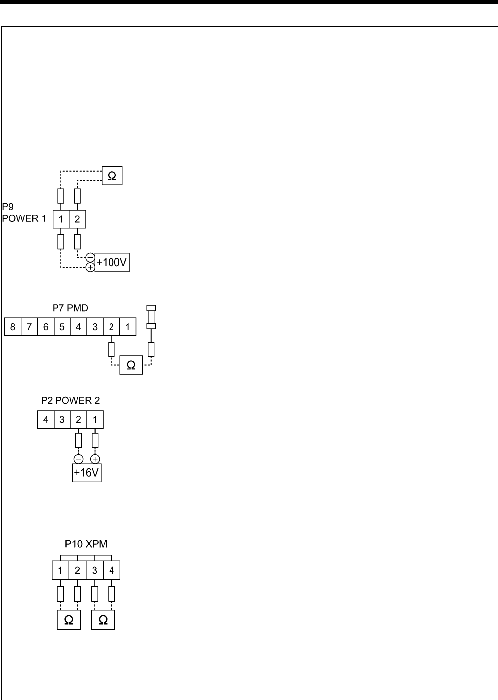
8. ELECTRICAL MECHANISM
214
RH-9820
Problem #5 When the start switch is depressed, an error code [E200] is displayed.
Cause Inspection/Remedy/Adjustment Replacement if a malfunction
1. If the X feed does not operate
and [E200] is displayed, there is
a blown fuse.
Remove fuse F2 from the power supply motor
P.C. board and check the continuity.
OK if continuity
(If there is no continuity, carry out the inspections
in 2.)
Fuse
6A-250V
2. If the X feed does not operate
and [E200] is displayed, there is
a malfunction of the PMD P.C.
board or of the power supply
motor P.C. board.
1) Disconnect connector P9 (POWER1) from
the PMD P.C. board and measure the
resistance between pins 1-2 at connector P9.
OK if ∞ Ω; if 0 Ω, there is a malfunction of the
PMD P.C. board.
2) Measure the resistance between the fuse F2
terminal that is close to P6 (MAIN) and pin 2
of connector P7 (PMD) on the power supply
motor P.C. board. (D10 check)
OK if ∞ Ω
3) Disconnect connector P9 (POWER1) from
the PMD P.C. board, and then measure the
voltage between pins 1-2 of the cord-side
connector.
OK if approx. +100 V
After measuring, turn off the power, wait 5
minutes or more and then insert P9.
4) Disconnect connector P2 (POWER2) from
the PMD P.C. board, and then measure the
voltage between pins 1-2 of the cord-side
connector.
OK if approx. +16 V
After measuring, turn off the power, wait 5
minutes or more and then insert P2.
5) Check that connector P1 (MAIN) is inserted
into the PMD P.C. board.
PMD P.C. board or power
supply motor P.C. board
3. If the feed mechanism does not
move and [E200] is displayed,
there is a malfunction of the
pulse motor or cord.
1) Disconnect connector P10 (XPM) from the
PMD P.C. board, and measure the resistance
between pins 1-2 and 3-4 at the cord-side
connector.
OK if 2−3 Ω
After measuring, insert P10.
2) If 1) is OK, there is a malfunction of the PMD
P.C. board.
Pulse motor assembly
PMD P.C. board
4. If the X feed moves slightly and
then [E200] is displayed, there
is a malfunction of the X axis
home position sensor (encoder).
1) Check that connector P20 (X-ENC) is
inserted into the main P.C. board.
2) Check the X axis home position sensor (encoder)
input while referring to “2-6. Input checking
method”.
Pulse motor X assembly
4884Q
4885Q
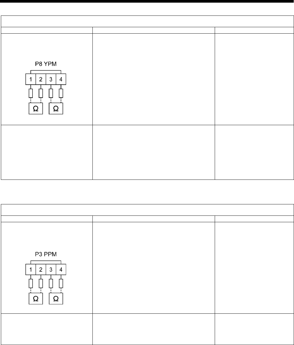
8. ELECTRICAL MECHANISM
215 RH-9820
Problem #6 When the start switch is depressed, an error code [E210] is displayed.
Cause Inspection/Remedy/Adjustment Replacement if a malfunction
1. If the feed mechanism does not
move and [E210] is displayed,
there is a malfunction of the
pulse motor or cord.
1) Disconnect connector P8 (YPM) from the
PMD P.C. board, and measure the resistance
between pins 1-2 and 3-4 at the cord-side
connector.
OK if 2-3 Ω
After measuring, insert P8.
2) If 1) is OK, there is a malfunction of the PMD
P.C. board.
Pulse motor Y assembly
PMD P.C. board
2. If the Y feed moves and then
[E210] is displayed, there is a
malfunction of the Y axis home
position sensor (proximity
sensor).
1) Check that connector P8 (SENSOR1) is
inserted into the main P.C. board.
2) Check the Y axis home position sensor input
while referring to “2-6. Input checking
method”.
3) If a metallic object is brought close to the Y
axis home position sensor and the LED
inside the sensor does not illuminate, there is
a malfunction of the sensor.
Y axis home position sensor
Problem #7 When the start switch is depressed, an error code [E220] is displayed.
Cause Inspection/Remedy/Adjustment Replacement if a malfunction
1. If the θ pulse motor does not
move and [E220] is displayed,
there is a malfunction of the
pulse motor or cord.
1) Disconnect connector P3 (PPM) from the
PMD P.C. board, and measure the resistance
between pins 1-2 and 3-4 at the cord-side
connector.
OK if 2-3 Ω
After measuring, insert P3.
2) If 1) is OK, there is a malfunction of the PMD
P.C. board.
Pulse motor P assembly
PMD P.C. board
2. If the θ pulse motor moves
slightly and then [E220] is
displayed, there is a malfunction
of the θ shaft home position
sensor (encoder).
1) Check that connector P5 (P-ENC) is inserted
into the main P.C. board.
2) Check the θ axis home position sensor
(encoder) input while referring to “2-6. Input
checking method”.
Pulse motor P assembly
4886Q
4888Q

8. ELECTRICAL MECHANISM
216
RH-9820
Problem #8 Work clamp is not lowered during sewing.
Cause Inspection/Remedy/Adjustment Replacement if a malfunction
Malfunction of valve or valve harness 1) Check that connector P12 (AIR1) is
inserted into the main P.C. board.
2) Check the air.
Valve harness
Problem #9 Hammer does not operate (When set to cutting before sewing).
Cause Inspection/Remedy/Adjustment Replacement if a malfunction
Malfunction of valve or valve harness Check that connector P25 (AIR2) is inserted
into the main P.C. board.
Valve harness
Problem # 10 Sewing machine does not operate during sewing and [E120] is displayed.
Cause Inspection/Remedy/Adjustment Replacement if a malfunction
1. Malfunction of sewing machine
motor cord
Check connector P4 (UVW) of the power
supply motor P.C. board and the sewing
machine motor connector.
Motor cable
2. If the fuse (F1) on the power supply
motor P.C. board is blown, there is
a malfunction of the main P.C.
board.
1) If the fuse (F1) is blown, check the
resistance values between all pins of the
connector P4 (UVW) and the pins of the
fuse (∞ Ω) and replace the fuse.
2) If the fuse blows again, replace the power
supply motor P.C. board.
Power supply motor P.C.
board
3. Sewing machine motor overheats
and the thermostat inside the motor
operates when the sewing machine
is operated at short cycle.
1) Turn off the power and let the sewing
machine stand for 30 minutes or more.
2) Turn the power back on; OK if operation is
normal.
Avoid repeated sewing of sewing data that is
less than 15 stitches.
Motor cable

8. ELECTRICAL MECHANISM
217 RH-9820
Problem #11 An error code is displayed after the sewing machine operates.
Cause Inspection/Remedy/Adjustment Replacement if a malfunction
1. If [E120] (Needle drop signal
error), [E130] (Upper shaft signal
error) or [E131] (Upper shaft
signal error) is displayed after
the sewing machine operates,
there is a malfunction of the
synchronizer, interference is
causing operating problems, or
the sewing machine is
incorrectly adjusted.
1) Check that connector P5 (SYNC) is inserted
into the power supply motor P.C. board and
that the synchronizer is connected.
2) If the needle drop signal or upper shaft
encoder signal can be confirmed to be
turning on and off while referring to “2-6.
Input checking method”, then they are OK.
3) Turn the pulley by hand and check that it
turns smoothly.
4) Check that connector P17 (M_MOTOR) is
inserted into the main P.C. board and that
connector P6 (MAIN) is inserted into the
power supply motor P.C. board.
5) Check the harness between connector P17
(M_MOTOR) of the main P.C. board and
connector P6 (MAIN) of the power supply
motor P.C. board.
6) Check that the ground wire is connected to a
secure ground and that there is no equipment
nearby that is generating strong electrical
interference.
Motor assembly CCD-9820
2. If [E150] is displayed after the
sewing machine operates, the
motor is abnormally overheating.
1) Turn off the power and let the sewing
machine stand for 30 minutes or more.
2) Turn the power back on; OK if operation is
normal.
Problem #12 Upper thread trimming does not operate.
Cause Inspection/Remedy/Adjustment Replacement if a malfunction
Malfunction of valve or valve harness Check that connector P12 (AIR1) is inserted
into the main P.C. board.
Valve harness
Problem #13 Needle does not stop in the up position. ([E111] is displayed.)
Cause Inspection/Remedy/Adjustment Replacement if a malfunction
1. Incorrect adjustment
Adjust while referring to “7-36. Adjusting the
upper shaft stop position”.
2. Malfunction of needle up signal Check the needle up signal input while referring
to “2-6. Input checking method”.
3. Malfunction of zigzag sensor 1) Check that connector P10 (SENSOR2) is
inserted into the main P.C. board.
2) Check the zigzag sensor while referring to
“2-6. Input checking method”.
Main P.C. board
4. Malfunction of cord Refer to inspection #10.
5. Malfunction of power supply
motor P.C. board
With connector P2 (POWER2) connected to the
PMD P.C. board, measure the voltage at the cord.
OK if approximately 30 V DC between pins 3-4.
Power supply motor P.C.
board
6. Malfunction of main P.C. board Main P.C. board
7. Malfunction of motor Motor
4892Q

8. ELECTRICAL MECHANISM
218
RH-9820
Problem #14 Lower thread trimming does not operate.
Cause Inspection/Remedy/Adjustment Replacement if a malfunction
Malfunction of valve or valve harness Check that connector P12 (AIR1) is inserted
into the main P.C. board.
Valve harness
Problem #15 Hammer does not operate (when set to cutting after sewing).
Cause Inspection/Remedy/Adjustment Replacement if a malfunction
Malfunction of valve or valve harness Check that connector P25 (AIR2) is inserted
into the main P.C. board.
Valve harness
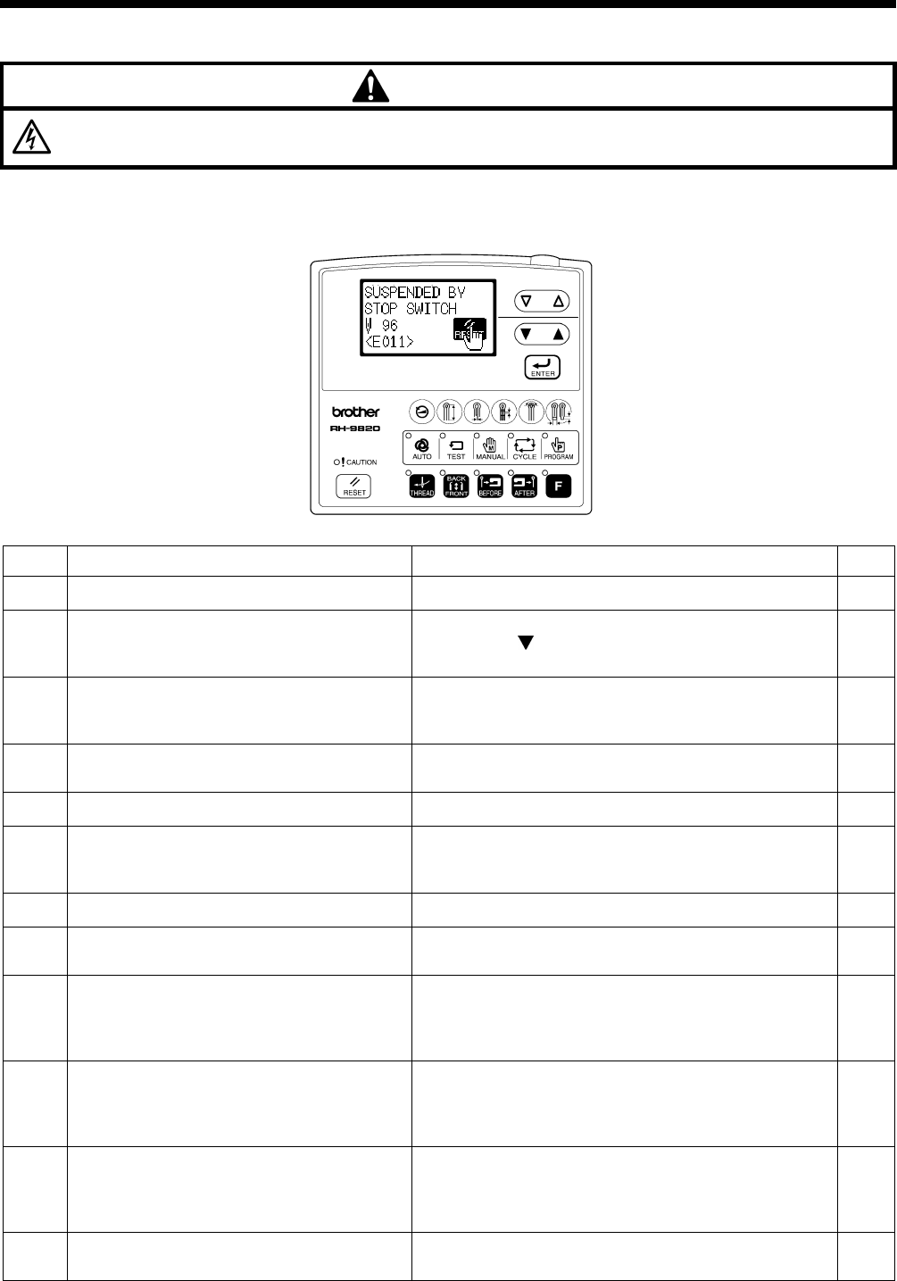
9. ERROR CODES
RH-9820
219
9. ERROR CODES
DANGER
Wait at least 5 minutes after turning off the power switch and disconnecting the power cord from the wall outlet before
opening the cover of the control box. Touching areas where high voltages are present can result in severe injury.
If a problem should occur with the sewing machine, the buzzer will sound and an error code and error message will appear in
the display.
Follow the remedy procedure to eliminate the cause of the problem.
Switch-related errors
Code Cause Remedy Page
E010 Stop switch was pressed during standby. Remove your finger from the stop switch (so that it is off). *1
E011 Stop switch was pressed during sewing.
Press the RESET key to clear the error.
* Press the key to move the feed mechanism so that
you can continue sewing.
*1
E015
The stop switch was still being pressed, or
there is a problem with the stop switch
connection.
Turn off the power, and check the stop switch if it was not
being pressed at the time. -
E016 Problem with the stop switch connection. Turn off the power and check the connection of the stop
switch connector P13 at the main P.C. board. 200
E024 Start switch is being pressed. Release the start switch (so that it turns off). *1
E025
Start switch was depressed after the power
was turned on, or connection of start switch is
defective.
Turn off the power and check if the start switch is pressed.
If the start switch is not being pressed, check the switch
connector P6 at the main P.C. board.
200
E034 Work clamp switch is being pressed. Release the work clamp switch (so that it turns off). *1
E035 Work clamp switch was depressed, or
connection of work clamp switch is defective. Turn off the power and check the work clamp switch. *1
E050 Machine head tilting was detected after the
power was turned on.
Turn off the power, and then return the machine head to
its original position.
Check the connection of the machine head safety switch
connector P9 at the main P.C. board.
200
E051 Machine head tilting was detected while the
sewing machine was operating.
Turn off the power, and then return the machine head to
its original position.
Check the connection of the machine head safety switch
connector P9 at the main P.C. board.
200
E055 Machine head tilting was detected when the
power was turned on.
Turn off the power, and then return the machine head to
its original position.
Check the connection of the machine head safety switch
connector P9 at the main P.C. board.
200
E065 An operation panel key was still being pressed
when the power was turned on, or key is faulty.
Turn off the power and check that no keys are being
pressed. -
*1:Refer to the reference page in “10. ERROR CODES” in the instruction manual.
0320B
0461B

9. ERROR CODES
RH-9820 220
Upper shaft motor-related errors
Code Cause Remedy Page
E110 Needle up stop position error
Turn the upper shaft pulley until the point where the error
display disappears.
If the error display does not disappear, turn off the power
and check the connection of the synchronizer connector
P5 at the power supply motor P.C. board.
201
217
E111 Needle up stop position error Turn off the power, and check the connection of the
synchronizer connector P5 at the main P.C. board.
201
217
E120 Needle drop signal could not be detected. Turn off the power, and check the connection of the
synchronizer connector P5 at the main P.C. board.
201
216
217
E130 Sewing machine motor stopped due to a
problem, or synchronizer is faulty.
Turn off the power, and then turn the upper shaft pulley
and check if the sewing machine has locked up.
Check that the upper shaft motor connector P4 and
synchronizer connector P5 are connected at the power
supply motor P.C. board.
201
217
E131 Synchronizer is faulty.
Turn off the power, and check the connection of the
synchronizer connector P5 at the power supply motor P.C.
board.
201
217
E132 Problem detected with sewing machine motor
operation.
Turn off the power, and then turn the upper shaft pulley
and check if the sewing machine has locked up.
Check that the upper shaft motor connector P4 and
synchronizer connector P5 are connected at the power
supply motor P.C. board.
201
E133 Sewing machine motor stopping position is
incorrect.
Turn off the power, and then turn the upper shaft pulley
and check if the sewing machine has locked up.
Check that the upper shaft motor connector P4 and
synchronizer connector P5 are connected at the power
supply motor P.C. board.
201
E140 Sewing machine motor operated in reverse
during sewing.
Turn off the power, and then turn the upper shaft pulley
and check if the sewing machine has locked up.
Check that the upper shaft motor connector P4 and
synchronizer connector P5 are connected at the power
supply motor P.C. board.
201
E150 Sewing machine motor is overheating, or
temperature sensor is faulty.
Turn off the power, and then turn the upper shaft pulley
and check if the sewing machine has locked up.
Check that the upper shaft motor connector P4 and
synchronizer connector P5 are connected at the power
supply motor P.C. board.
201

9. ERROR CODES
RH-9820
221
Feed mechanism-related errors
Code Cause Remedy Page
E200
X-feed motor home position cannot be
detected.
Problem with X-feed motor or poor X home
position sensor connection.
Turn off the power, and then check that the X-feed motor
connector P10 is connected at the PMD P.C. board and
that the X pulse motor encoder connector P20 is
connected at the main P.C. board.
200
201
214
E201 X-feed motor stopped due to a problem. Turn off the power, and then check if there are any
problems in the X-feed direction. -
E210
Y-feed motor home position cannot be
detected.
Problem with Y-feed motor or poor Y home
position sensor connection.
Turn off the power, and then check that the Y-feed motor
connector P8 is connected at the PMD P.C. board and that
the Y pulse motor encoder connector P4 and sensor
connector P8 are connected at the main P.C. board.
200
201
215
E211 Y-feed motor stopped due to a problem. Turn off the power, and then check if there are any
problems in the Y-feed direction. -
E220
θ-feed motor home position cannot be
detected.
Problem with θ-feed motor or poor θ home
position sensor connection.
Turn off the power, and then check that the θ-feed motor
connector P3 is connected at the PMD P.C. board and that
the θ-feed motor encoder connector P5 is connected at
the main P.C. board.
200
201
215
E221 θ-feed motor stopped due to a problem. Turn off the power, and then check if there are any
problems in the θ-feed direction. -
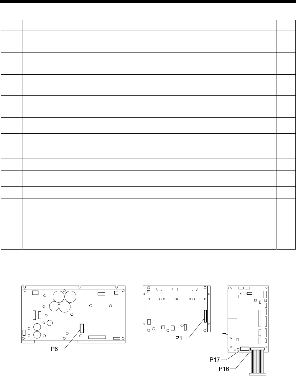
9. ERROR CODES
RH-9820 222
Communication and memory-related errors
Code Cause Remedy Page
E401
Connection error detected between the main
P.C. board and power supply motor P.C.
board when the power was turned on.
Turn off the power, and then check that connector P17 on
the main P.C. board and connector P6 on the power
supply motor P.C. board are properly connected.
200
201
E403
Communication error detected between the
main P.C. board and PMD P.C. board when
the power was turned on.
Turn off the power, and then check that connector P16 on
the main P.C. board and connector P1 on the PMD P.C.
board are properly connected.
200
201
E410 Communication error between main P.C.
board and panel P.C. board detected.
Turn off the power, and then check that the operation
panel connector P1 is connected at the main P.C. board.
200
201
E411
Communication error between main P.C.
board and power supply motor P.C. board
detected.
Turn off the power, and then check that connector P17 on
the main P.C. board and connector P6 on the power
supply motor P.C. board are properly connected.
200
201
E420 No CF card is inserted.
(No messages are displayed.)
Turn off the power, and then insert a CF card into the CF
card slot of the control box. -
E422 Error occurred while reading CF card. Check the data on the CF card. -
E424 Insufficient free space on CF card. Use a different CF card. -
E425 Error occurred while writing to CF card. Use the specified type of CF card. -
E430 Problem with flash memory on main P.C.
board. Turn the power off and then back on again. -
E440 Problem with EEPROM on main P.C. board. Turn the power off and then back on again. -
E450 Model selection cannot be read from the
machine head memory.
Turn off the power, and check the connection of the
machine head memory connector P3 at the power supply
motor P.C. board.
212
E451 Data cannot be backed up to machine head
memory. Turn the power off and then back on again. -
E480 Problem with RAM on main P.C. board. Turn the power off and then back on again. -
[P.C. board and connector positions]
Power supply P.C. board PMD P.C. board Main P.C. board
0535B

9. ERROR CODES
RH-9820
223
Software-related errors
Code Cause Remedy Page
E569*2 Program version error between main and
motor detected.
Press the RESET key to clear the error.
* This error is displayed when a power supply motor
P.C.board for a different model is installed.
Replace with the power supply motor P.C.B. for the
RH-9820 as soon as possible.
198
E580 Error in EEPROM version detected. Turn off the power and carry out level 3 initialization. *3
E581 Error in memory switch version detected. Turn off the power and carry out level 2 initialization. *3
E582 Error in parameter data version detected. Turn off the power and carry out level 1 initialization. *3
*2:If the version of the main control program (MN) is 1.0.00, this error (E569) will not be displayed.
*3:Refer to “7-3. Resetting the data (initialization)” in the instruction manual.
Device-related errors
Code Cause Remedy Page
E600 Upper thread breakage occurred.
Thread the upper thread, and then press the RESET key
to clear the error.
* Press the key to move the feed mechanism so that
you can continue sewing.
*4
E601 Upper thread breakage detector is not
connected.
Turn off the power and check the connection of the stop
switch connector P13 at the main P.C. board. 200
E630 Lower thread trimmer does not operate,
or lower thread trimming sensor is faulty.
Turn off the power, and then check that the valve harness
connector P12 and sensor connector P10 are inserted at
the main P.C. board.
200
E650 Hammer is lowered, or hammer position
sensor is faulty.
Turn off the power, and then check that the hammer valve
harness connector P25 and hammer position sensor
connector P3 are inserted at the main P.C. board.
200
E651 Hammer is not lowered, or hammer
position sensor is faulty.
Turn off the power, and then check that the hammer valve
harness connector P25 and hammer position sensor
connector P3 are inserted at the main P.C. board.
200
*4:Refer to the reference page in “10. ERROR CODES” in the instruction manual.
P.C. board-related errors
Code Cause Remedy Page
E700 Abnormal rise in power supply voltage. Turn off the power and check the input voltage. 212
E701 Abnormal rise in sewing machine motor
drive voltage. Turn off the power, and then check the voltage. -
E705 Abnormal drop in power supply voltage. Turn off the power and check the input voltage. 212
E710 Abnormal current detected in sewing
machine motor.
Turn off the power, and then check if there are any
problems with the sewing machine. -
E719 Problem detected with PMD P.C. board. Turn off the power, and then check the PMD P.C. board. -
E740 Cooling fan does not operate. Turn off the power, and then check that the cooling fan
sensor connector P8 is connected at the main P.C. board. -

9. ERROR CODES
RH-9820 224
Optional device-related errors
Code Cause Remedy Page
E940
Sub-hammer is not set even though
straight buttonhole program is being
sewn. (Straight buttonhole position
sensor is not responding.)
Turn off the power, and then check that connector P12
and connector P24 on the main P.C. board are properly
connected.
*5
E941
Sub-hammer is not retracted even though
eyelet buttonhole program is being sewn.
(Eyelet buttonhole position sensor is not
responding.)
Turn off the power, and then check that connector P12
and connector P24 on the main P.C. board are properly
connected.
*5
E942
Sewing machine is trying to sew an eyelet
buttonhole while there is no material
under the straight buttonhole sensor.
Sewing machine is trying to sew a straight
buttonhole while there is material under
the straight buttonhole sensor.
Press the RESET key. *5
E950
No response from feed plate home
position sensor while feed plate is being
driven.
Turn off the power, and then check that connector P23
and connector P25 on the main P.C. board are properly
connected.
*5
E951 No response from feed plate left sensor
while feed plate is being driven.
Turn off the power, and then check that connector P23
and connector P25 on the main P.C. board are properly
connected.
*5
E952 No response from feed plate right sensor
while feed plate is being driven.
Turn off the power, and then check that connector P23
and connector P25 on the main P.C. board are properly
connected.
*5
*5:Refer to the instruction manuals for the corresponding devices.
If an error code that is not listed above appears or if carrying out the specified remedy does not solve the problem, contact the
place of purchase.
10. TROUBLESHOOTING
RH-9820
225
10. TROUBLESHOOTING
• If there is a problem with operation, first check that the threads are correctly threaded and that the needle is correctly
installed.
• Please check the following points before calling for repairs or service.
• If the following remedies do not fix the problem, turn off the power switch and consult a qualified technician or the place of
purchase.
CAUTION
Turn off the power switch and disconnect the power cord before carrying out troubleshooting.
Otherwise the machine may operate if the start switch is pressed by mistake, which could result in serious injury.
Problem Cause Remedy Page
Thread tension is too strong. Adjust the thread tension to the correct
tension.
Instruction
manual
Needle is not installed correctly. Install the needle so that it faces
correctly.
Instruction
manual
Thread is too thick for the needle. Select a thread which is suitable for the
needle.
Instruction
manual
Needle and looper adjustment is
incorrect.
Adjust the clearance between the
needle and looper, the needle bar height
or the looper and spreader height.
141, 148
149
Needle, looper, spreader, throat plate or
thread path is damaged. Repair or replace the respective part(s).
Thread breaks
Thread is not threaded correctly. Thread the thread correctly. Instruction
manual
Upper thread tension is too strong or too
weak.
Adjust the upper thread tension to the
correct tension.
Instruction
manual
Needle point is broken or bent. Replace with a new needle.
Clearance between needle and looper
tip is incorrect.
Adjust the clearance between the
needle and looper tip. 149
Needle, looper and spreader adjustment
is incorrect. Adjust correctly. 141
146 - 151
Needle and needle guard adjustment is
incorrect. Adjust the needle guard. 149
Eye looper tip is blunt. Repair with an oilstone or replace the
looper with a new one.
Needle is not installed correctly. Install the needle so that it faces
correctly.
Instruction
manual
Skipped stitches occur.
Needle is too thin. Select a needle that is suitable for the
sewing conditions.
Instruction
manual

10. TROUBLESHOOTING
RH-9820 226
Problem Cause Remedy Page
Needle is bent. Replace with a new needle.
Needle, looper and spreader adjustment
is incorrect. Adjust correctly. 141
146 – 151
Needle guard is covering the needle too
far. Adjust the needle guard. 149
Broken needle
Needle is too thin. Select a needle that is suitable for the
sewing conditions.
Instruction
manual
Upper movable knife is blunt. Replace the upper movable knife with a
new one. 166, 167
Upper movable knife does not move to
the full stroke because air pressure is
too weak.
Adjust the air pressure. Instruction
manual
Upper movable knife is not picking up
the upper thread.
Install the upper movable knife so that it
cuts only one side of the upper thread
loop.
167
Upper movable knife is not picking up
the upper thread because the last stitch
is being skipped.
Refer to the remedies given under
“Skipped stitches occur” in this
troubleshooting chart.
225
Upper thread is not cut.
Upper movable knife position is
incorrect.
Adjust the position of the upper movable
knife. 167
Movable knife is blunt. Replace the movable knife with a new
one. 169, 174
Movable knife does not move to the full
stroke because air pressure is too weak. Adjust the air pressure. Instruction
manual
Movable knife position is incorrect. Adjust the position of the movable knife
or the thread handler.
170, 173
175
Lower thread is not cut.
Cutting pressure for lower thread
trimming is too weak.
Adjust to an appropriate cutting
pressure. 170, 174
Lower thread is not being held.
Adjust the lower thread nipper (-01
specifications) or the lower thread
presser (-02 specifications).
171, 173
180
Upper thread length is too short after
trimming. Adjust the sub tension. Instruction
manual
Thread unravelling at
sewing start
Not enough upper thread is being fed
out.
Adjust the amount of upper thread being
fed out. 165
Cutting pressure is too weak. Adjust the cutting pressure so that it is
strong enough. 160
Knife and hammer are not contacting
properly. Grind the hammer surface. 154
Material is not being cut
cleanly.
Knife is blunt. Replace the knife with a new one. 157
Upper thread tension is too strong or too
weak.
Adjust the upper thread tension to the
correct tension.
Instruction
manual
Lower thread tension is too strong or too
weak.
Adjust the lower thread tension to the
correct tension.
Instruction
manual
Poor thread tightening
Tension or stroke of thread take-up
spring is incorrect.
Adjust the tension and stroke of the
thread take-up spring.
Instruction
manual

SERVICE MANUAL
RH-9820
I6100920B
2007. 03. B (1)
Printed in Ja
p
an
