ACE&EASTMAN Sc 380Em01 E SC380*P001 User Manual
2016-09-16
User Manual: ACE&EASTMAN Sc-380Em01 E
Open the PDF directly: View PDF ![]() .
.
Page Count: 148 [warning: Documents this large are best viewed by clicking the View PDF Link!]
- CONTENTS
- 1. DRIVE UNIT SAFETY INSTRUCTION
- 2. POINTS OF CAUTION
- 3. NAMES OF EACH PARTS
- 4. INSTALLATION
- 5. WIRE AND GROUNDING
- 1. Insertion of the power connector
- 2. Connection of 3-phase power
- 3. Power capacity
- 4. When using the 3-phase 200 V class SC-380 with Single- phase 200 to 220 V class
- 5. When using the single phase 100 V SC-380 with single phase 110 V to 120 V
- or 3-phase 200 to 220 V SC-380 with 3-phase 220V to 240V
- 6. To change solenoid voltage
- 7. When using the single-phase 220V servomotor in the 380V area
- 6. CONFIRMATION
- 7. ADJUSTMENTS
- 8. PEDAL OPERATION
- 9. OPERATION OF THE OPERATION PANEL KEYS
- 1) Displays during normal mode and functions of each key
- 2) Selection of each mode
- 3) HOW TO USE PROGRAM MODES [1] AND [2]
- Table of simplified setting value for JUKI sewing machine with thread trimmer
- 4) How to use the normal mode
- 5) Display and function of each key in the tacking mode and pattern mode. (for lock stitch machine)
- 10. HOW TO USE THE PROGRAM MODE (EXAMPLE OF MOST FREQUENTLY USING)
- 1) To change the maximum speed
- 2) To change the number of stitches in slow start
- 3) To apply a weak break during stopping
- 4) To set the standing work type
- 5) To change input/output port function
- 6) To set external one shot signal
- 7) To set number of stitches to the needle UP position stop after detecting the fabric end with an optical sensor, etc.
- 8) To continue presser foot lifting after the thread trimming, and to bring down
- the presser foot after the time set on the timer has passed
- 9) To set needle position higher than usual after thread trimming
- 10) To adjust the correlation between toe down angle speed
- 11) To run without the detector (when the detector is broken)
- 12) To adjust tacking accurately
- 13) To check the error codee history and input/output signal
- 14) To return all setting to the factory settings
- 11. HOW TO SET COUNTER FUNCTION
- 12. SETTING IN THE THREAD TRIMMING MODE TR
- 13. OUTPUT TB, TF TIMINGS
- 14. OUTPUT KS1, KS2, KS3 TIMINGS
- 15. SIMPLE SEQUENCE
- 16. COMMUNICATION FUNCTION
- 17. HOW TO CHANGE VOLTAGE OF PANEL CONNECTOR AND SOLENOID RETURN SPEED
- 18. HOW TO SET THREAD BREAK DETECTOR
- 19. CUTTER OUTPUT
- 20. TABLE OF PROGRAM MODE FUNCTIONS
- 21. INPUT/OUTPUT FUNCTION FOR SIGNAL ON C MODE SETTING
- 22. THE COMPOSITION FIGURE OF INPUT AND OUTPUT CUSTOMIZATION
- 23. HOW TO USE THE OPTION CONNECTOR
- 24. ERROR DISPLAY
- 25. SPECIFICATIONS
- <REFERENCE> TABEL OF DIGITAL DISPLAY
- Front page

R
ENGINEER’S MANUAL
29320900
No.01
Sewing machine controller
SC-380
PREFACE
This Engineer’s Manual is written for the technical personnel who are responsible for the service and maintenance
of the machine.
The Instruction Manual for these machines intended for the maintenance personnel and operators at an apparel
factory contains operating instructions in detail. And this manual describes “Standard Adjustment”, Adjustment
Procedures”, “Results of Improper Adjustment”, and other important information which are not covered in the
Instruction Manual.
It is advisable to use the relevant Instruction Manual and Parts List together with this Engineer’s Manual when
carrying out the maintenance of these machines.
This manual gives the “Standard Adjustment” on the former page under which the most basic adjustment value
is described and on the latter page the “Results of Improper Adjustment” under which stitching errors and
troubles arising from mechanical failures and “How To Adjust” are described.
CONTENTS
1. DRIVE UNIT SAFETY INSTRUCTIONS.............................................................. 1
2. POINTS OF CAUTION ........................................................................................ 3
3. NAMES OF EACH PARTS .................................................................................. 5
4. INSTALLATION ................................................................................................... 6
1.Installation of the motor........................................................................................................ 6
2. Installation of the control box. ............................................................................................ 6
3. Installation of the pulley ...................................................................................................... 6
4. Mounting of the belt. ............................................................................................................ 7
5. Installation of the protective cover ..................................................................................... 7
6. Installation of the position detector.................................................................................... 9
7. Connection of the lever unit ................................................................................................ 9
8. Connection of the sewing machine and control box. ..................................................... 10
5. WIRE AND GROUNDING.................................................................................. 11
1. Insertion of the power connector...................................................................................... 11
2. Connection of 3-phase power ........................................................................................... 11
3. Power capacity ................................................................................................................... 11
4. When using the 3-phase 200 V class SC-380 with Single- phase 200 to 220 V class .. 12
5. When using the single phase 100 V SC-380 with single phase 110 V to 120 V
or 3-phase 200 to 220 V SC-380 with 3-phase 220 V to 240 V ........................................ 12
6. To change solenoid voltage .............................................................................................. 13
7. When using the single-phase 220V servomotor in the 380V area ................................. 14
6. CONFIRMATION ............................................................................................... 15
1. Before turning switches on…............................................................................................ 15
2. Thrn on the power …… ...................................................................................................... 16
7. ADJUSTMENTS ................................................................................................ 17
1. Adjustment of stopping position ...................................................................................... 17
2. Adjustment of pedal toe down pressure, and heeling pressure .................................... 17
3. Adjustment of operation speed......................................................................................... 18
8. PEDAL OPERATION......................................................................................... 19
9. OPERATION OF THE OPERATION PANEL KEYS ......................................... 20
1) Displays during normal mode and functions of each key.............................................. 20
2) Selection of each mode ..................................................................................................... 20
3) HOW TO USE PROGRAM MODES [1] AND [2]................................................................. 24
Table of simplified setting value for JUKI sewing machine with thread trimmer............. 25
4) How to use the normal mode ............................................................................................ 27
5) Display and function of each key in the tacking mode and pattern mode.
(for lock stitch machine) .................................................................................................... 28
(1) Tacking setting mode (At the time of patter No.=4, this mode will be skipped.) ........................................... 28
(2) No. of tacking stitches setting mode. ............................................................................................................ 29
(3) Preset stitching setting mode ........................................................................................................................ 30
10.
HOW TO USE THE PROGRAM MODE (EXAMPLE OF MOST FREQUENTLY USING) ......
31
1) To change the maximum speed ........................................................................................ 31
2) To change the number of stitches in slow start .............................................................. 31
3) To apply a weak break during stopping ........................................................................... 32
4) To set the standing work type........................................................................................... 32
5) To change input/output port function. ............................................................................. 33
6) To set external one shot signal......................................................................................... 37
7) To set number of stitches to the needle UP position stop after detecting
the fabric end with an optical sensor, etc. ....................................................................... 38
8) To continue presser foot lifting after the thread trimming, and to bring down
the presser foot after the time set on the timer has passed .......................................... 39
9) To set needle position higher than usual after thread trimming ................................... 39
10) To adjust the correlation between toe down angle speed ........................................... 40
11) To run without the detector (when the detector is broken).......................................... 40
12) To adjust tacking accurately ........................................................................................... 41
13) To check the error code history and input/output signal ............................................. 43
14) To return all setting to the factory settings ................................................................... 45
11. HOW TO SET COUNTER FUNCTION ............................................................ 46
1. To use the counter function .............................................................................................. 46
2. Down counter for bobbin remain thread count (10,000 stitches is count over) ........... 48
3. How to Adjust current count amount to use input signal. ............................................. 50
12. SETTING IN THE THREAD TRIMMING MODE TR ........................................ 51
1) Thread trimming timing when thread trimming mode TR setting is PRG..................... 51
2) Sewing machine motion pattern ....................................................................................... 53
13. OUTPUT TB, TF TIMINGS .............................................................................. 55
1) Output normal timing .........................................................................................................55
2) Function setting [RU [ON]] in program mode P .............................................................. 55
14. OUTPUT KS1, KS2, KS3 TIMINGS ................................................................ 56
15. SIMPLE SEQUENCE....................................................................................... 57
1. Simple sequence starting conditions ............................................................................... 57
2. Simple sequence output timing chart .............................................................................. 57
3. When starting condition setting [SQS] is [NO] (default setting) .................................... 58
4. Example of simple sequence setting................................................................................ 58
16. COMMUNICATION FUNCTION ...................................................................... 59
1. About the communication ................................................................................................. 59
2. Wiring .................................................................................................................................. 59
3. The basic procedure ..........................................................................................................60
4. The communication command list ................................................................................... 61
17.
HOW TO CHANGE VOLTAGE OF PANEL CONNECTOR AND SOLENOID RETURN SPEED ..
64
1. To change Solenoid voltage 24 V/30 V. ............................................................................ 64
2. How to change the output voltage DC5 V/12 V ................................................................ 64
3. How to set the switch for increasing the solenoid return speed. .................................. 66
18. HOW TO SET THREAD BREAK DETECTOR ................................................ 67
1. Setting Thread break detector function ........................................................................... 67
2. Timing chart of thread break input and output................................................................ 68
19. CUTTER OUTPUT........................................................................................... 69
1) Cutter ................................................................................................................................... 69
2) BT specifications (*1) operation chart and required settings ........................................ 70
20. TABLE OF PROGRAM MODE FUNCTIONS.................................................. 71
21. INPUT/OUTPUT FUNCTION FOR SIGNAL ON C MODE SETTING ........... 126
1. C mode input signal setting table ................................................................................... 126
2. C mode output signal setting table................................................................................. 130
22. THE COMPOSITION FIGURE OF INPUT AND OUTPUT CUSTOMIZATION ....... 132
1. Input and output customization ...................................................................................... 132
2. Input/output direct coupling port (inside connecting port) .......................................... 133
3. Connector input/output common port............................................................................ 134
23. HOW TO USE THE OPTION CONNECTOR................................................. 135
1) Connector layout .............................................................................................................. 135
2)The explanation of the input/output signal ..................................................................... 137
3) To use as a standing work type sewing machine. ........................................................ 139
24. ERROR DISPLAY.......................................................................................... 140
25. SPECIFICATIONS ......................................................................................... 141
<REFERENCE> TABEL OF DIGITAL DISPLAY ................................................ 142
− 1 −
1. DRIVE UNIT SAFETY INSTRUCTIONS
1. To ensure safe use
– Always observe the following items to ensure safe use of the industrial sewing machine drive unit SC-
380.
1.1 Before starting
– Read all instruction manual thoroughly before starting use of this drive unit,and follow the Engineer’s
Manual. Also read the instruction manuals for the installed sewing machine.
1.2 Application and purpose
– This drive unit is designed to drive a sewing machine and must not be used for other applications or
purposes. Do not use this drive unit until it can be confirmed that safety measures for the installed
sewing machine have been taken.
1.3 Work environment
– Use this drive unit in dry and well-kept clean locations,e.g. in the clothing industry, and which process
dry sewing material.
– Avoid using this control unit in the following types of environments.
(1) Power voltage
– Place where voltage fluctuation exceeds ±10 % of the rated voltage.
– Place where frequency fluctuation exceeds ± 1 % of 50/60 Hz.
– Place where the specified power capacity cannot be secured.
(2) Electromagnetic noise
– Place where strong electric or magnetic fields are generated such as near a large-output high frequency
oscillator or high frequency welding machine.
(3) Temperature and humidity
– Place where atmospheric temperature is 40 ˚C or higher and 5 ˚C or lower.
– Place subject to direct sunlight or outdoors.
– Near a heat source such as a heater.
– Place where relative humidity is 30 % or less and 95 % or more, or where dew condensation occurs.
(4) Atmosphere
– Atmosphere with dust or corrosive gases.
– Atmosphere with combustible gases or explosive atmosphere.
(5) Altitude
– Place where at altitudes exceeds 1,000 m above mean sea level.
(6) Storage
– Place where storage temperature is 55 ˚C or higher and –25 ˚C or lower.
(7) Vibration
– If excessive vibration occurs when the control box is installed on the sewing machine, install it separately.
2. Installation
2.1 Motor and control box
– Correctly install according to the attached Engineer’s Manual.
2.2 Accessories
– Always disconnect this control unit from the main power supply when installing any accessories listed in
the Engineer’s Manual. (Turn the main switch OFF, and remove the plug from the outlet (power supply
line).)
2.3 Cable
(1) Arrange the connection cable so that excessive force is not applied during use, and do not excessively
bend the cable.
(2) Cables near moving parts (e.g., pulley or V-belt) must be wired at a minimum distance of 25 mm.

− 2 −
(3) Confirm that the power voltage of the power cable for supplying to the control box meets the specifications
on the motor and control box rating nameplates before connecting it to the power line. Connect it to the
designated places to supply the power. Perform this step with the power ON/OFF switch turned OFF.
2.4 Grounding
(1) Correctly connect the control box grounding to the power supply grounding.
2.5 Accompanying appliances and accessories
(1) Electric accompanying appliances and accessories must only be connected to safely low voltage.
2.6 Removal
(1) Turn the main switch OFF and remove the plug from the outlet Åipower supply lineÅjbefore removing
the motor or control box.
(2) Do not pull on the cord when removing the plug. Always hold the plug itself.
(3) There is a high voltage applied inside the control box, so always wait at least 10 minutes after running
the power switch OFF and remove the plug from the outletÅipower supply lineÅjbefore opening the
control box panel.
3. Maintenance, inspection and repairs
– Follow the Engineer’s Manual for maintenance and inspection of the this control unit.
– Repairs and maintenance must be done and approved by specially trained personnel.
– Do not run this control with the ventilation openings of the motor’s dust-proof filter blocked or clogged
with dust, loose cloth, etc.
– Always turn the power switch OFF and remove the plug from the outlet Åipower supply lineÅjbefore
replacing the sewing machine needle or bobbin, etc.
– Always use original replacement parts for repairs or maintenance.
4. Other safety measures
– Keep fingers away from all moving partsÅiespecially near sewing machine needle, V-belt, etc.Åj.
– Do not drop this control unit or insert any object into any opening.
– Do not operate without required protective devices.
– If any damage is observed on this control unit, if the drive does not run properly or if operator is uncertain
about operation, do not operate the drive unit. Operate the drive only after adjustments, repairs and
approvals have been made by qualified personnel.
– The user must avoid making modifications or changes based on user’s judgment.
Observe all safety guidelines if modifications or changes must be made.
5. Hazard display, warning display
(1) Risks that may cause personal injury or risk to
the machine ate marked with this symbol in the
instruction manual.
(2) This symbol indicates electrical risks and
warnings.
Save these Engineer’s Manual for future reference.
− 3 −
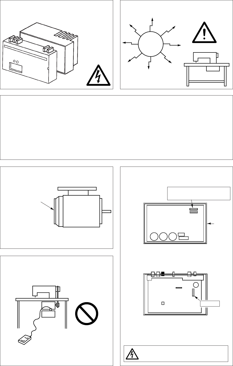
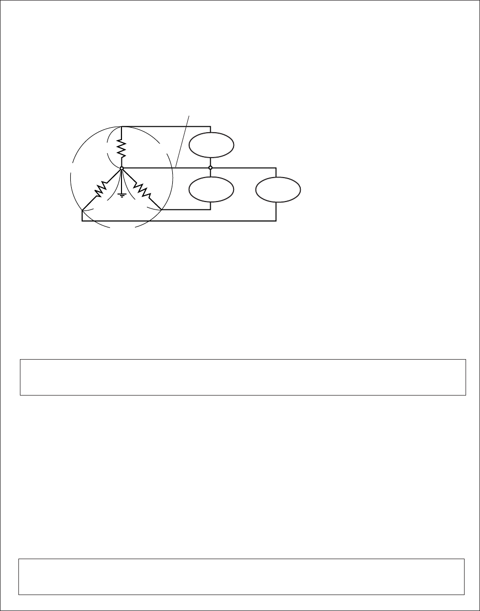
5. Always ground the machine.
The 3-phase motor has a grounding wire
(green) (green/yellow). Always ground this.
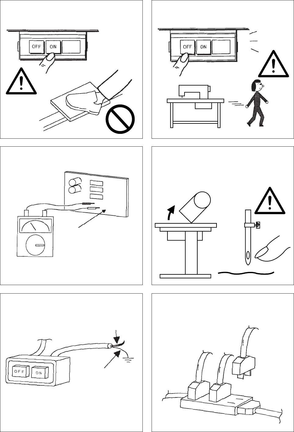
2. POINTS OF CAUTION
1. Please remove your foot from the pedal
when turning the power ON.
2. Always turn the power OFF when leaving
the machine.
3. Do not inspect the control circuit with a
tester.
The semiconductor parts may be damaged
when the tester’s voltage is applied.
4. Always turn the power switch OFF before
tilting the sewing machine head, replacing
the needle, or threading the needle.
6. Do not use branched wiring when using the
single-phase motor.
Control circuit
Sewing
machine
Needle
Power
Green/Yellow
(Green)
− 4 −
15.If the fuse, remove the cause, and replace the
blown fuse with one having the same capacity.
200 V Two fuses
100 V One fuse
(Front view with cover removed.)
* The above fuses is for protection of the control
box power supply section.
(View from back of cover)
* The above 8 A fuse is for protection of the
solenoid output power supply (30 V/24 V)
section.
Wait 10 minutes after turning the power
switch OFF before opening the cover
7. A high voltage is applied inside the machine,
so wait 10 minutes after turning the power switch
OFF before opening the cover.
8. Use the machine away from sources of strong
noise such as a high frequency welder.
9. The brakes may not function when the power is turned OFF or when there is a power failure during sewing
machine operation.
10. Match the connector shape and direction, and insert securely.
11. An optical method is used for the detector’s detection element so take care not to let dust or oils get on the
detection plate when removing the cover for adjustment, etc. If these do get on the plate, wipe off with a soft
cloth and do not scratch the plate. Take care not to let oils enter between the detector discs.
12. When the position detector connector turned OFF after a set time to prevent damage to the motor.
(The motor may not turn OFF if the locking is not complete.) After the problem has been resolved, turn the
power OFF and ON and normal operation will be possible. The same operation should be taken when the
detector or wires are broken.
13. Remove the dust that has adhered on the
motor’s dust-proof filter once every two to three
weeks.
14. When connecting the external switch to the
option connector, etc., keep the signal wire as
short as possidle. If it is long, malfunctions may
occur.
High voltage
danger
a
a
Noise
Dust-proof filter
If the motor is run while
the filter is clogged, the
motor may overheat
and affect the motor
life.
Box
Two 20 A Fuses (XC-EJK)
Two 15 A Fuses (XC-EJKCE)
8A Fuse
¡Use a shield cable for the signal wire when
possible.
− 5 −
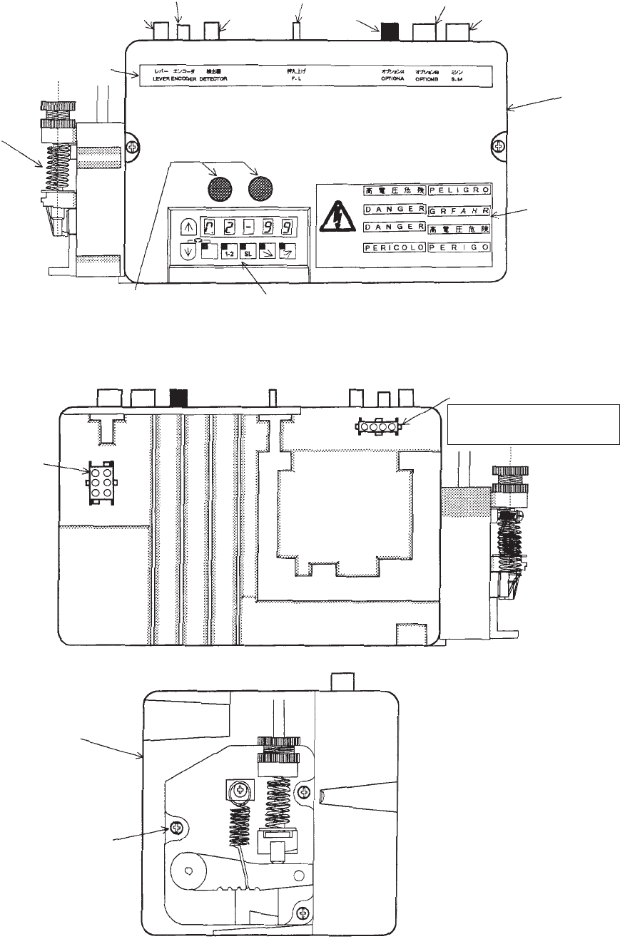
3. NAMES OF EACH PARTS
1. Front
2. Rear
3. Left
Communication connector and
Control panel connector
(Both connector can be connected
to each one)
Lever Unit
Connector display
nameplate
Lever connector
Encoder
connector Detector
connector
Presser foot
lifter connector
Option A connector
Option B
connector
Sewing Machine
connector
Cover
Operation panel
High voltage
warning plate
Motor connector
White connector for 100 V
Brown connector for 200 V
Incoming power
connector
Box
Screw hole for lever
installation (M5 screw)
− 6 −
3. Installation of the pulley
Securely tighten the pulley.
Select the correct pulley diameter to ensure complete use of the motor performance.
Selection of the motor pulley :
Motor pulley outer diameter (mm) = x + 5 mm
※The motor speed should be set at 3,600 r/min. When the motor pulley diameter is selected with the
above method and the pulley diameter is too small, select the minimum pulley in the range that the
belt will not slip.
※Refer to page 28 for the pulley diameter to be used when using the Mitsubishi thread trimming
sewing machine.
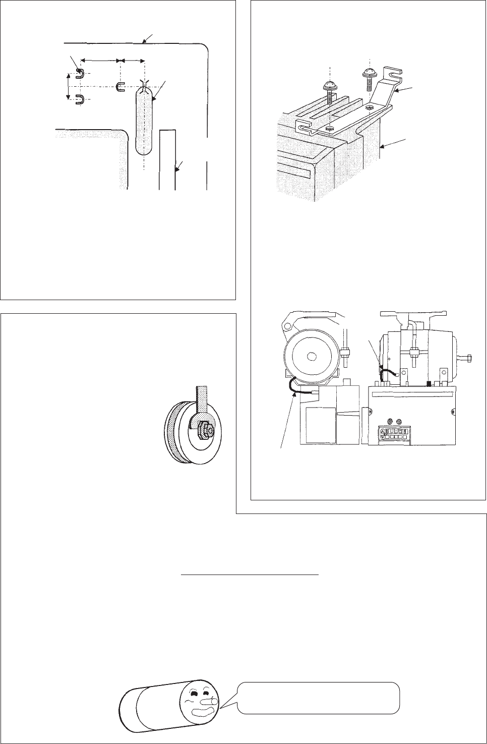
4. INSTALLATION
1. Installation of the motor
Using the hole opening pattern, open three 9
mm holes on the table. Install the motor
securely using the installation bolts, washers,
spring washers and nuts.
The pattern and installation bolts, etc., are
included with the motor as accessories.
2. Installation of the control box.
(1) Install the two enclosed installation plates
on the control box.
(2) Next, tighten the control box onto the motor.
(3)Insert the power cord from the motor into
the connector on the back of the control box.
Insert the encoder cord from the motor into
the encoder connector on the front of the
control box.
3-9 cut hole
Table
66
159 57
Belt hole
Bobbin
winder
Control box
Power cord from motor
100 V : White connector
200 V : Brown connector
Installation
plate
Encoder
cord
(Caution)
Incomplete tightening may
cause malfunctions.
Motor pulley diameter
(effective diameter)
Normal sewing machine speed
※Motor speed
Select the correct pulley diameter.
− 7 −
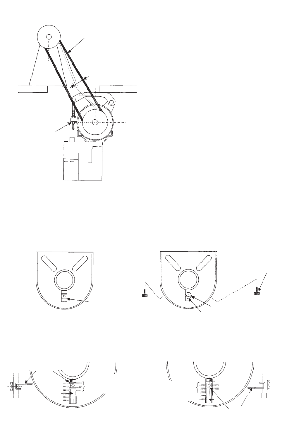
4. Mounting of the belt.
To adjust the belt tension, press down on the
center of the belt with your hand, and turn the
upper and lower nuts of the adjustment nut to
increase or decrease the center height of the
motor so that the belt dips approximately 15 mm.
(Caution) If the belt tension is too low, the
medium and low speeds will be
inconsistent, and the stopping
precision will be poor. When too
tight, the motor bearings will
deteriorate.
Use the JIS K6323 sewing
machine belt M-type.
15 mm
(approx. 9.8N)
Adjustment nut
5. Installation of the protective cover
(1) Installation of the protective cover (with belt slip off prevention part)
The protective cover is enclosed with the motor as an accessory.
View from back of protective cover View from front of protective cover
¡Change the direction of the long and short side of the attachment plate according to the motor pulley
outer diameter.
(a) For motor pulley outer diameter ø55 to ø80 (b) For motor pulley outer diameter ø80 to ø125
¡Set the center of the washer to the pulley diameter indication scale and tighten the butterfly bolt.
¡Confirm that the belt does not contact the attachment plate.
Attachment
plate
Protective cover
installation screw
(View from back of protective cover) Attachment plate
rectangle side
Washer
Butterfly bolt
Attachment plate
rectangle side
Cross-
section
A-A
A
A
Pulley outer diameter
ø55 to ø80 indication
scale (front) Pulley outer diameter
ø80 to ø125 indication
scale (front)
(View from back of protective cover)
B
B
Cross-
section
B-B
− 8 −
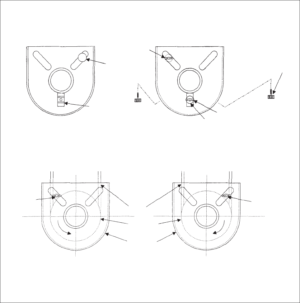
(2) Installation of the protective rod.
The protective rod is enclosed as a motor accessory.
Looking from rear of protective cover Looking from front of protective cover
¡Set the protective rod to the motor pulley rotation direction and install between the belt and motor
pulley.
(a) For counterclockwise rotation (b) For clockwise rotation
¡Set the center of the protective rod to the position at the center of the belt and motor pulley and
tighten the thumb nut.
¡Confirm that the belt and motor pulley do not contact the protective rod.
Installation
plate
Protective cover
installation screw
(Looking from front of protective cove) (Looking from front of protective cover)
Protective
rod
Thumb
nut
Washer
Thumb bolt
Protective
rod Belt
Motor
pulley
Protective
cover
Protective
rod
− 9 −
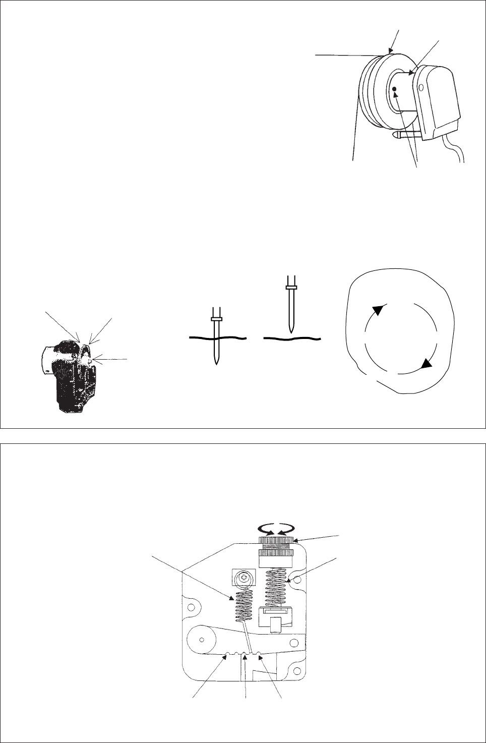
6. Installation of the position detector
(1) The installation of the position detector will differ
according to the sewing machine model, so
please consult with your sewing machine model
dealer for details.
The diagram on the left shows an example of
the position detector installation.
(2) Insert the connector from the position detector
into the control box position installation.
(3) To prevent malfunctions caused by static
electricity, connect the grounding wires (green/
yellow) from the position detector onto the
sewing machine head.
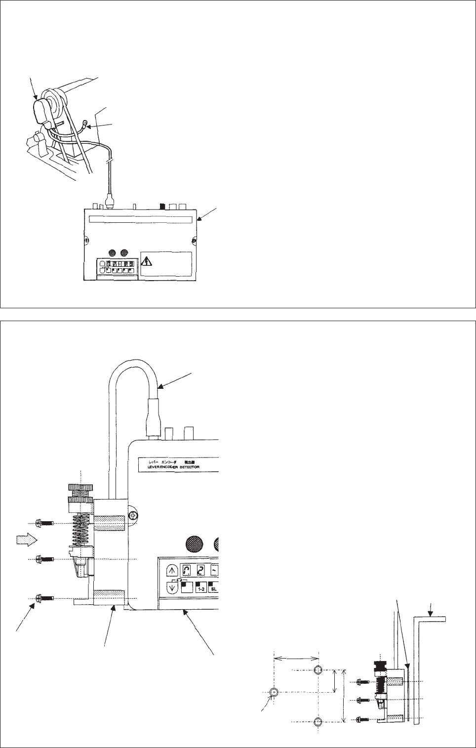
7. Connection of the lever unit
(1) Insert connector from the lever unit into the lever
connector of the control box.
(2) When removing a lever unit from the control box
and then setting it independently.
1. As for the installation size, refer to the lever
unit installation size of the following figure.
2. Refer to the way of the following figure of
installing a lever unit and install a way of
installing.
In installation, always keep the sheet metal
between lever unit and the installation board.
Position detector
Grounding wire
(green/yellow)
Control box
Control box
Installation
board
Lever unit
wire
Screw
(Three places) Lever unit
(Example) The way of installing a lever unit
The lever unit installation size
(figure which is seen from A)
M5x3 screw
78
20.5
66
Sheet
metal
− 10 −
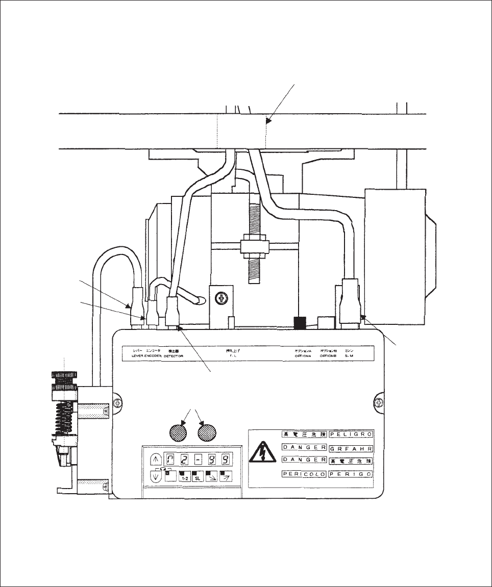
8. Connection of the sewing machine and control box.
Wire the units as shown below.
(Caution) For safety, always turn the power switch OFF and wait for the panel display [PWR.OF]
(displayed for approx. 10 seconds) before connecting or disconnecting the plugs.
This [PWR.OF] display is not an error.
Communication connector and Control panel connector
(Both connector can be connected to each)
Table hole
Connector
for lever
Connector
for encoder
Connector for
sewing machine
Connector for detector

− 11 −
5. WIRE AND GROUNDING
1. Insertion of the power connector
Confirm the connector from and insertion direction when inserting the power connector into the control
box and insert completely.
3. Power capacity
Use a fuse or complete breaker for the power
2. Connection of 3-phase power
Rear control box
Ground the green (green/yellow) wire
to the grounding terminal. Consult with
an electrician for the grounding wires.
Incoming power
connector
Power connector
(6-Pole)
Red
White
Black
Green
(green/yellow)
Cord for push-button switch
3-phase power
R-phase S-phase T-phase
Power
Single phase
100-120 V 550 W
200-240 V 550 W
3-phase
200-240 V 550 W
Recommended power capacity
15 A
10 A

− 12 −
4. When using the 3-phase 200 V class SC-380 with Single- phase 200 to 220 V class
¡Connect the “red”and”white”lead wires from the push-button switch to the power.
The black wire is not used.
Tape it with insulation tape, etc., to insulate securely.
Always ground the green/yellow (green) grounding wire.
5. When using the single phase 100 V SC-380 with single phase 110 V to 120 V or
3-phase 200 to 220 V SC-380 with 3-phase 220 V to 240 V
(1) Remove the cover.
(2) Reconnect the connector from [CON5] to [CON6] (110-120 V/220-240 V)
(3) After change, always set the cover of control box.
(4) Change the mark “○” display on the factory shipment voltage nameplate on the side of the control
box.
Do not connect.
(Securely insulate by taping.)
Control box
Reconnect to here. Reconnect to here.
Connection connector
to control box Push-button switch
Green/yellow
(Green)
Connect to grounding
terminal.
Red
White
Black
Connect these
lead wires to
the power
− 13 −
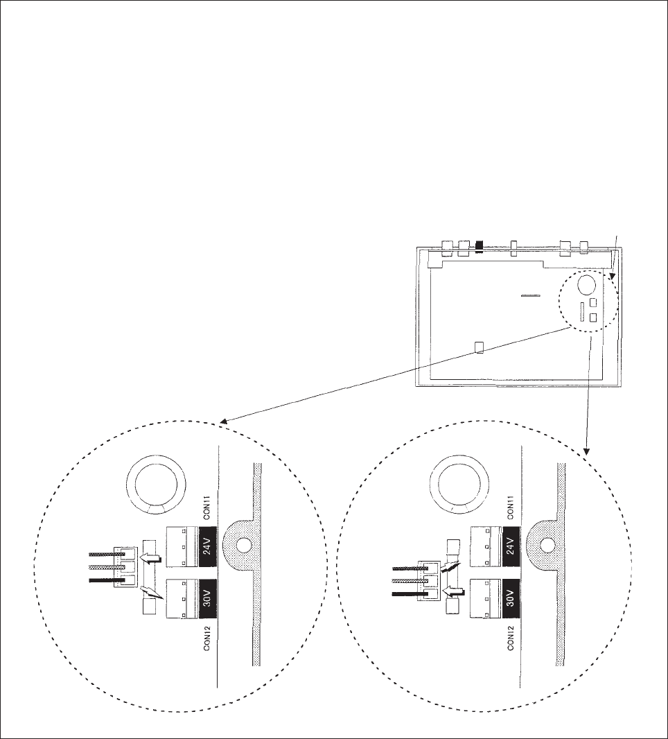
6. To change solenoid voltage
To change solenoid voltage from 24 V to 30 V
(1) Remove the cover.
(2) Reconnect the connector from [CON11] to [CON12] (30 V)
(3) After change, always set the cover to the control box.
To change solenoid voltage from 30 V to 24 V
(1) Remove the cover.
(2) Reconnect the connector from [CON12] to [CON11] (24 V)
(3) After change, always set the cover to the control box. Cover
From 24 V to 30 V From 30 V to 24 V
Reconnect to here. Reconnect to here.
− 14 −
7. When using the single-phase 220V servomotor in the 380V area
Note) For the single phase 220V, refer to “[5] 4. When using the three phase 200V SC-380 with
single phase 200 to 220V class”.
(1) Connecting the power
1When there is a neutral wire :
2When there is no neutral wire :
Singlephase 220V is generally used for the residence in the 380V area.
Connect the wire from the single phase 220V power.
(2) Caution
1Connect equal number of motors to the respective phases, R, S, and T as shown in the above
illustration so that the load of 3-phase power is not unbalanced.
2Change the voltage in the control box to 220 to 240V.
Refer to “[5] Wire and Grounding 5. When using the single phase 100V SC-380 with single phase
110V to 120V or 3-phase 200 to 220V SC-380 with 3-phase 220 to 240V”.
3For the overseas market, use the motor after checking whether the voltage is in the range of
220$$240V since there is a case where voltage regulation is high.
4Connect the servomotor after checking whether or not the wiring in the factory is mistaken
(especially connecting mistake of the neutral wire).
(3) Others
Even the 3-phase 200V motor (for domestic market) can be used in the single phase 200 to 220V
area by changing wiring of the push button section. In addition, it can be used in the 220 to 240V
area by changing the connecting position of the connector as shown in the illustration of the previous
item.
Refer to “[5] Wire and Grounding 4. When using the 3-phase 200V class SC-380 with Single-
phase 200 to 220V class”.
Connect the ground wire of
motor to the neutral wire.
Neutral wire
R
S
T
220V
380V
380V
220V 220V
380V 1ø 220V
Motor
1ø 220V
Motor 1ø 220V
Motor
− 15 −
6. CONFIRMATION
1. Before turning switches on…..
Reference
Current capacity on page 11.
XC-EJK-20-05 (JE : XC-EJKCE20-05) (200 V type)
XC-EJK-10-05 (100 V type)
Installation of control box on page 6.
Installation of lever unit on page 9.
Installation of position detector on page 9.
–––
Mounting of the belt on page 7.
Installation of the pulley on page 6.
–––
Place to confirm
(1) Is the power and capacity suitable?
(2) Is the power voltage the same as the ○ mark on
the factory preset voltage nameplate on the side of
the control box? (XC-EMFY Control Box)
(3) Are the connectors inserted correctly ?
• Power connector from push-button switch
• Motor connector
• Motor encoder connector
• Lever connector
• Position detection connector
• Other connectors (options, presser foot lifter
control switch panel, etc.)
(4) Is the lead wire contacting the V belt ?
(5) Is the belt tension okay ?
(6) Are the pulley nuts securely tightened ?
(7) Can the sewing machine be rotated lightly by hand
?
POWER UNIT L20E
200-220 V
○220-240 V
OUTPUT
550 W
POWER UNIT L10E
100-110 V
○110-120 V
OUTPUT
550 W
− 16 −
2. Thrn on the power ……
(1) Does the position detector lamp light?
(2) Does the LED on the control box operation panel light ?
(3) Is the sewing machine rotation direction correct ?
•For left rotation (CCW)
•For right rotation (CW)
Refer to page 26 for the procedure fir changing the rotaition.
(4) Is there any heat, odors or abnormal sounds coming from the motor of control box ?
Operation panel
MA
1-2
B
SL
CD
Position detector
Operation panel
The sewing machine rotation direction is determined with
the rotation direction of this LED.
The sewing machine rotates to the
left looking from the pulley side.
The factory setting is left rotation.
The sewing machine rotates to the
right looking from the pulley side.
Turn off the power if there is any heat, odors or abnormal
sounds coming from the motor or control box.
Contact your dealer immediately.
− 17 −
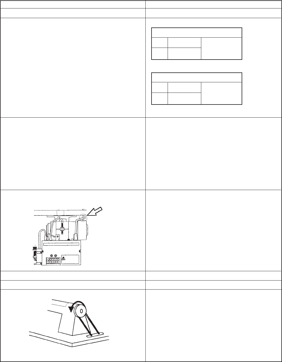
7. ADJUSTMENTS
1. Adjustment of stopping position
Adjust this position with the detector installed onto the sewing
machine and while stopping at the UP and DOWN positions.
For safety, disconnect the connector for the sewing machine.
(1) Adjustment of UP position
• Loosen the two set screws on the detector joint, and set the
stop position by rotating by hand.
• If adjustment is not possible by turning the joint, loosen the cross-
recessed screw A shown in the figure below, and turn all detector
plates simultaneously to adjust to the designated stop position.
(2) Adjustment of DOWN position
• The relation of the DOWN position and UP position will differ
according to the model, so adjust this according to the sewing
machine.
• When changing the DOWN position , remove the detector cover, and turn only the red detector
plate to adjust to the designated stop position.
(The cross-recessed screw A does not need to be loosened at this time.)
• Always replace the cover after adjustment.
(Caution) Refer to the sewing machine instruction manual when adjusting for use with the.
2. Adjustment of pedal toe down pressure, and heeling pressure
The pedal toe down force can be adjusted by changing the hooking position of spring A to the lever.
(five level is available)
Turn the screw bolt to adjust the spring B pressure.
(The factory setting of the clearance from the
DOWN position to UP position is approx. 180)
Screw bolt
Detector joint
Sewing machine
pulley
Set screws
(two screws)
DOWN position UP position
Factory setting
UP position
180 ˚ 180˚
DOWN position
Speed, UP position
detector disc
(black) (inner)
DOWN position
detector plate
(red) (outer)
Screw A
Spring A
Minlmum spring
pressure Medium spring
pressure Maximum spring
pressure
Spring B
− 18 −
3. Adjustment of operation speed
Note *: There is not output of the solenoid, but it is possible to set speed.
(Caution) No matter how large the motor pulley diameter is, the speed will not rise higher than
the maximum speed H and the speed set with the [C]key and [D] key.
Adjustment of each speed
Maxim speed H
Low speed L
Thread trimming speed T
Start tack speed N
End tack speed V
Slow start speed S
Operation speed
Reference
Refer to program mode [P].
Refer to program mode [P].
Refer to program mode [P].
Refer to program mode [P].
Refer to program mode [P].
Refer to program mode [P].
The speed can be adjusted from low to maximum the
[C] key and [D] key on the operation panel.
Adjustment
range with the
[C]key and
[D]key.
Rotation speed
99
0
Maximum speed
Low speed
MA
1-2
B
SL
CD
It is possible to adjust
between 0 and 99.
[C] key [D] key
− 19 −
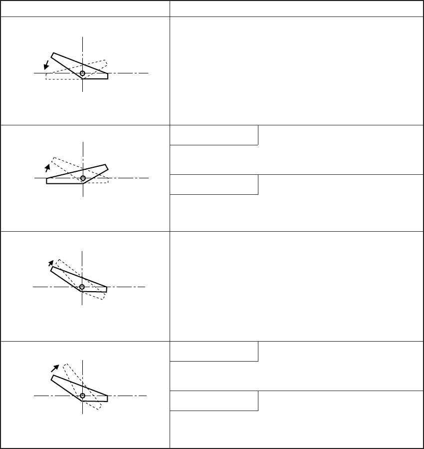
8. PEDAL OPERATION
(Caution) Refer to the explanation of [A] key “ How to use normal mode” page 27 for details on
setting the 1 position and 2 position.
Pedal operation
Neutral—Toe down
Toe down—Neutral
Neutral—Light heeling
Neutral—Full heeling
Operation
The sewing machine will rotate at a speed that is relevant
to the toe down amunt.
1 position setting
Needle UP position stop
2 position setting
Needle DOWN position stop
Presser foot lifter operation
1 position setting
Operation of needle UP position stop.
2 position setting
Needle UP position with half-rotation.
− 20 −
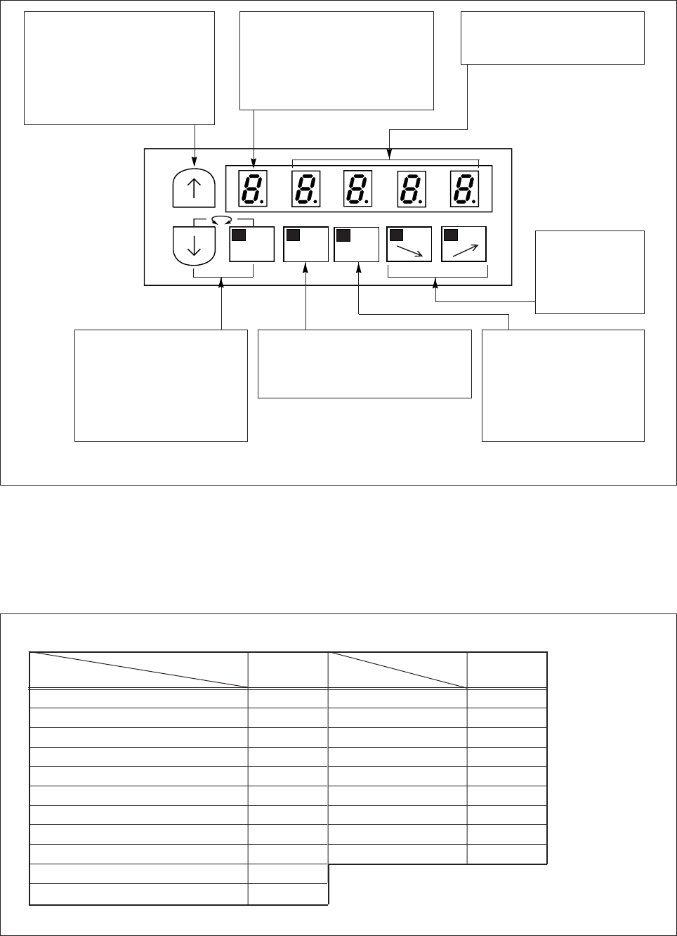
9. OPERATION OF THE OPERATION PANEL KEYS
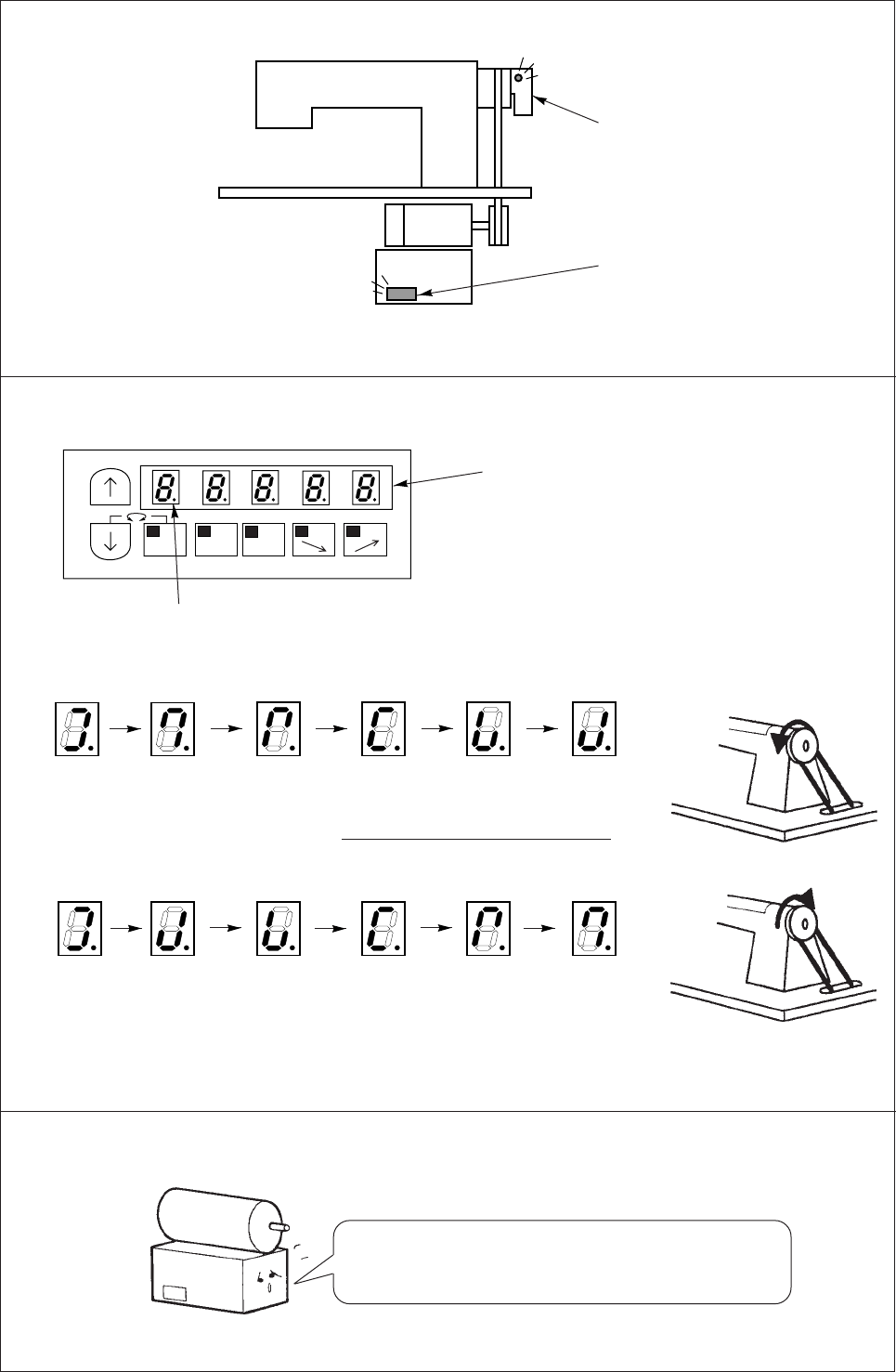
1) Displays during normal mode and functions of each key
When the power supply switch is turned ON, the rotation direction will display on the LED.M shown below.
When the rotation direction isn’t displayed on LED.M, press the [ ↓] key anytime.
This state is called the normal mode, and the following keys can be operated.
2) Selection of each mode
The modes can be changed from the normal mode to various program modes and various basic functions
and application functions set with this operation panel.
(For each mode function, refer to a table of program mode function.)
(1) Program mode and model
Note) This above keys can be operated only when the rotary display is shown on the LED.M.
LED.M
The rotation direction of the
sewing machine is displayed.
The rotation direction can be
changed with the [ ↓] + [M]
keys
MA
1-2
B
SL
CD
[↑] Up key
The validity of start and end
tacking stitch and number of
stitches can be set.
And the validity and No. of
stitches of preset stitching can
be set.
[↓] Down key, [M] key
By operating these two keys
simultaneously, the rotation
direction of the sewing
machine can be changed.
The display is shown on
LED.M.
[A] key
1 position and 2 position can be
selected for the needle position
during stopping.
[B] key
This is used to start
sewing with a slow start.
After the power is turned
ON and after thread
trimming, the sewing will
start with a slow start.
[C] key, [D] key
The speed at
which the pedal
is fully toed
down is set.
LED.A-D
The state of the [A] to [D] keys
function setting is shown.
Model
Model name
Program mode [F] ○
Program mode [G] ○
Program mode [H] ○
Program mode [J] ○
Program mode [Q] ○
Program mode [R] ○
Program mode [S] ○
Program mode [1] ○
Program mode [2] ○
Model
Model name
Normal mode ○
Tacking setting mode ○
No.of tacking stitches setting mode ○
Preset stitching setting mode ○
Pattern No. selection mode ○
Program mode [P] ○
Program mode [A] ○
Program mode [B] ○
Program mode [C] ○
Program mode [D] ○
Program mode [E] ○
SC-380SC-380
− 21 −
(3) Types of program mode
Program mode [P] The setting to often use 1 *Sewing machine,
etc.
Program mode [A] The setting to often use 2 *Servo motor,etc.
Program mode [B] The setting to often use 3 *Counter/Speed
display, etc.
Program mode [C] In/Out definition mode
(setting in/output signal to function,etc)
Program mode [D] Tacking setting mode
Program mode [E] H/W checking mode/Recorder of running.
Program mode [F] Cutter setting mode
Program mode [G]Thread trimming timing setting mode
Program mode [H] Setting speed limit setting mode
Program mode [J] Panel switch cancel mode
Program mode [Q] Unusual speed setting mode
Program mode [R] Reset/returning to original data.
(Return to factory setting)
Program mode [S] Simple sequence mode
Program mode [1] Simple setting mode for Mitsubishi thread
trimming sewing machine.
Program mode [2] Simple setting mode for chain stitch sewing
machine.
Tacking (condensed stitch) mode, preset stitching setting mode,
pattern select mode.
Normal mode
(The rotation direction is
displayed on LED.M)
(Caution) A different program mode cannot be entered from the program mode. To change the
program mode, always return to the normal mode first.
− 22 −
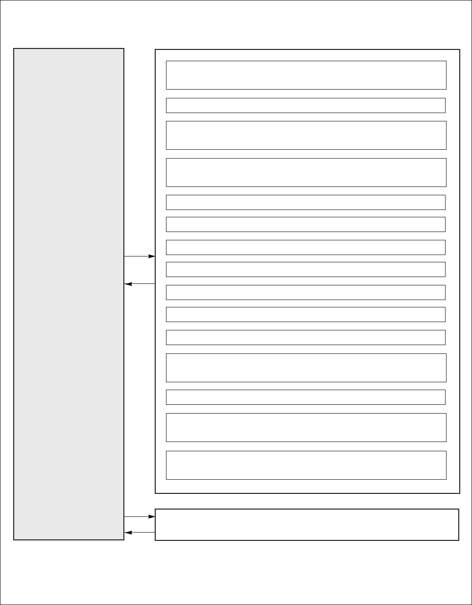
(3) Selection of each program mode from the normal mode.
Mode mane
Tacking type setting
mode
No. of tacking stitch
setting mode
Preset stitching setting
mode
Pattern No. selection
mode
Program mode [P]
Program mode [A]
Program mode [B]
Program mode [C]
Program mode [D]
Program mode [E]
Program mode [F]
Program mode [G]
Key operation
Press the key one time
from the normal mode.
Press the key two times
form the normal mode.
Press the key three times
form the normal mode.
Press the key four times
form the normal mode.
While holding down the
key, press the key for 2
seconds or more from normal
mode.
While holding down the
key, press the
A
1-2
key for 2
seconds or more from normal
mode.
While holding down the
key, press the
B
SL
key for 2
seconds or more from normal
mode.
While holding down the
key, press the
C
key for 2
seconds or more from normal
mode.
While holding down the
key, press the
D
key for 2
seconds or more from normal
mode.
While holding down the
key, press the
A
1-2
key and
the key for 2 seconds or
more from normal mode.
While holding down the
key, press the
B
SL
key and
the key for 2 seconds or
more from normal mode.
While holding down the
key, press the
C
key and
the key for 2 seconds or
more from normal mode.
Digital display
* The tacking setting mode will
be entered.
Note) Skipping about this menu at the time of pattern No.
= 4.
* The tacking stitches setting
mode will be entered.
* The tacking stitches setting
mode will be entered.
Note) Skipping about this menu at the time of pattern A to
H.
* The pattern No. selection mode
will be entered.
* The display will flicker.
* The program mode [P] will be
entered.
* The display will flicker.
* The program mode [A] will be
entered.
* The display will flicker.
* The program mode [B] will be
entered.
* The display will flicker.
* The program mode [C] will be
entered.
* The display will flicker.
* The program mode [D] will be
entered.
* The display will flicker.
* The program mode [E] will be
entered.
* The display will flicker.
* The program mode [F] will be
entered.
* The display will flicker.
* The program mode [G] will be
entered.
Return to the
normal mode
Press key
any time.
Press key
any time.
Press key
any time.
Press key
any time.
While holding
down key,
press key.
While holding
down key,
press key.
While holding
down key,
press key.
While holding
down key,
press key.
While holding
down key,
press key.
While holding
down key,
press key.
While holding
down key,
press key.
While holding
down key,
press key.
MA
1-2
B
SL
CD
− 23 −
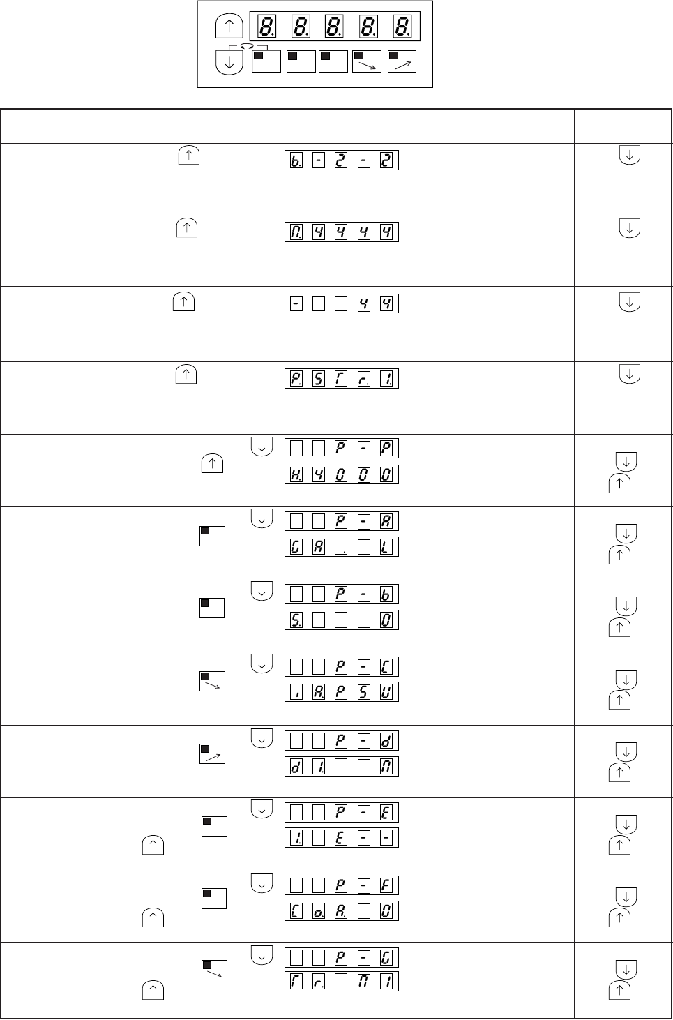
Mode mane
Program mode [H]
Program mode [J]
Program mode [Q]
Program mode [R]
Program mode [S]
Program mode [1]
Program mode [2]
Key operation
While holding down the
key, press the
D
key and
the key for 2 seconds or
more from normal mode.
While holding down the
key, press the key and the
A
1-2
key and the
B
SL
key for
2 seconds or more from
normal mode.
While holding down the
key, press the
A
1-2
key and
the
C
key for 2 seconds or
more from normal mode.
While holding down the
key, press the
B
SL
key and
the
C
key for 2 seconds or
more from normal mode.
While holding down the
key, press the
B
SL
key and
the
D
key for 2 seconds or
more from normal mode.
While holding down the
key, press the
A
1-2
key and
the
B
SL
key for 2 seconds or
more from normal mode.
While holding down the
key, press the
C
key and
the
D
key for 2 seconds or
more from normal mode.
Digital display
* The display will flicker.
* The program mode [H] will be
entered.
* The display will flicker.
* The program mode [J] will be
entered.
* The display will flicker.
* The program mode [Q] will be
entered.
* The display will flicker.
* The program mode [R] will be
entered.
* The display will flicker.
* The program mode [S] will be
entered.
* The display will flicker.
* The program mode [1] will be
entered.
* The display will flicker.
* The program mode [2] will be
entered.
Return to the
normal mode
While holding
down key,
press key.
While holding
down key,
press key.
While holding
down key,
press key.
Press
D
key
for 2 seconds or
more.
While holding
down key,
press key.
Press
D
key
for 2 seconds or
more. (*1)
Press
D
key
for 2 seconds or
more. (*1)
Note (*1) : It is set by pressing [D] key for over two seconds.
It is possible to return to normal mode by holding down [↑], [↓] key, but in this case
it is not set to new setting.
− 24 −
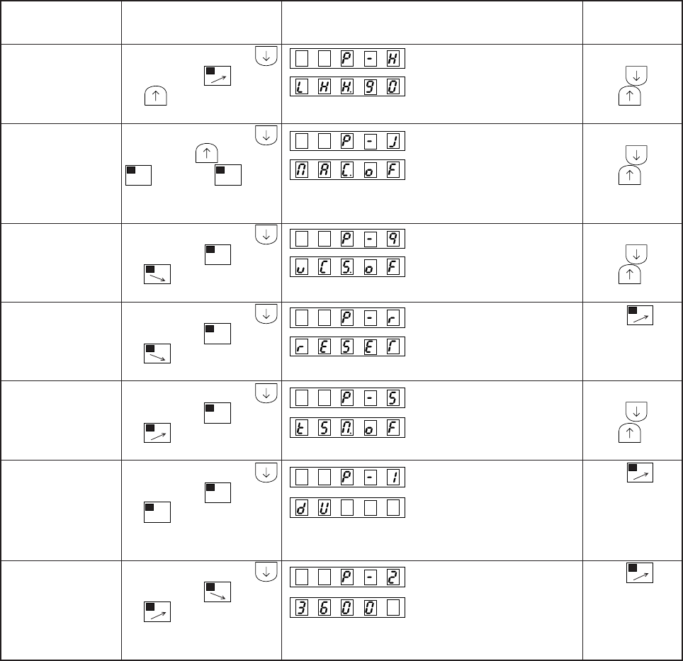
3) HOW TO USE PROGRAM MODES [1] AND [2]
(1)PROGRAM MODE [1]
(SEWING MACHINE HEAD FOR LEATHER AND HEAVY-WEIGHT MATERIALS)
To set the functions for the sewing machine with thread trimmer for leather and heavy-weight materials.
(ex.To set for the DNU-241H) ............................................................................... Function setting [DNU4]
1 Enter program mode [1] ([ ↓] + [A] + [B])
2* Program mode [1] will be entered.
3* Set function to [DNU4].
4* [DNU4] will flicker when [D] key is pressed.
5* Press [D] key (2 seconds or mode) to return to the
normal mode.
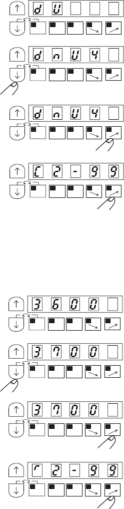
(2) THE PROGRAM MODE [2] (CHAINSTITCH SEWING MACHINE HEAD)
To set the functions for the chainstitch sewing machine head
1 Enter program mode [2] ([ ↓] + [C] + [D])
2* Program mode [2] will be entered.
3* Set function to [3700]
4* [3700] will flicker when [D] key is pressed.
5* Press [D] key (2 seconds or more) to return to the
normal mode.
Description
A. Select the function name that corresponds to the sewing machine model from “Table of simplified setting value for
JUKI sewing machine with thread trimmer” described in the next page. Press [D] key for 2 seconds or more, and
the number of revolution of the function name and connector function setting can be automatically set.
B. To return to the normal mode from the [dU] display, press the [↓] key while holding down [↑] key. In
the case, [dU] will not be set, and the last settings will be used.
C. Each time the [ ↓] key is pressed in step 3, the function will change in order from [dU] [dnU4] [LZH]
[dSU] …[U639]. (The factory setting is [LU2v].)
(Note) In case of SC-380, when this setting function is performed, all contents which have been set
so far are cleared and the number of revolution and function which correspond to the selected
sewing machine model can be set automatically.
MA
1-2
A
SL
CD
MA
1-2
A
SL
CD
MA
1-2
A
SL
CD
MA
1-2
A
SL
CD
MA
1-2
A
SL
CD
MA
1-2
A
SL
CD
MA
1-2
A
SL
CD
MA
1-2
A
SL
CD
− 25 −
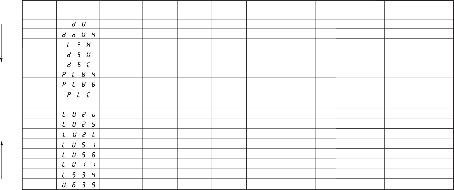
Program mode [1] (Machine head for leather and heavy-weight materials)
Note1.
Rotating
direction
Function
name
7 segment display Sewing machine
model
High speed
(H)
Low speed
(L)
Thread trimming
speed (T)
Start tacking
speed (N)
End tacking
speed (V)
Slow start
speed (S)
Slow start number
of stitches (SLN)
Connector
function setting
dU DU-141H 2000 200 200 600 600 200 1 CCW A
dnU4 DHU-241H 2400 200 170 820 820 200 0 CCW A
LZH LZH-1290 2000 185 185 490 490 190 1 CCW A
dSU DSU-14 *2000 170 170 1270 1270 170 1 CCW A
dSC DSC-24 *2200 185 185 570 570 190 1 CCW A
PLW4 PLW-124 *2500 180 180 570 570 180 1 CCW A
PLW6 PLW-126 *2500 180 180 570 570 180 1 CCW A
PLC PLC-1660 2000 170 170 1200 1200 170 1 CCW A
PLC-1610
LU2v
LU-22 *0 (VR type)
3500 170 170 1200 1200 170 0 CCW B
LU2s
LU-22 *0 (SW type)
3500 170 170 1200 1200 170 0 CCW C
LU2L LU-2216 3000 170 170 1200 1200 170 0 CCW B
LU51 LU-1510 3000 170 170 600 600 170 1 CCW D
LU56 LU-1560 2500 170 170 600 600 170 1 CCW D
LU11 LU-1114 2500 170 170 600 600 170 1 CCW A
LS34 LS-341N 2000 170 170 1200 1200 170 1 CCW A
U639 63900 4000 250 180 – – 250 3 CCW N
Note) 1. Each time the [ ↓] key is pressed, a function name is displayed in order to the direction of ↓.
2. Each time the [ ↑] key is pressed, a function name is displayed in order to the direction of ↑.
(Caution) Be sure to select the function name corresponding to the machine head used. If the selection is mistaken, damage to the machine head, control box
or motor may result. (However, the actual number of rotations is limited by the machine head used.)
Note2.
Table of simplified setting value for JUKI sewing machine with thread trimmer
− 26 −
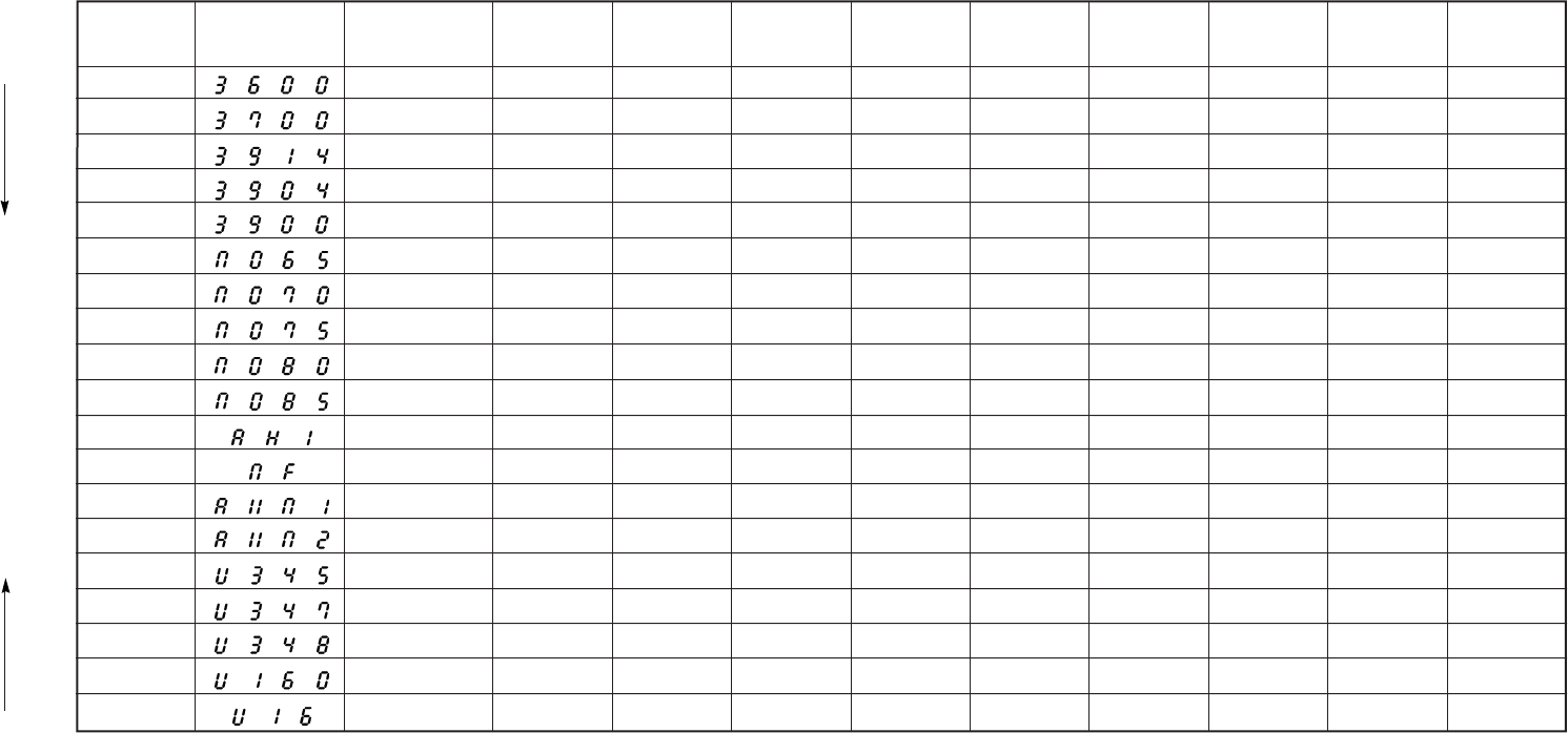
Program mode [2] (Chainstitch machine head)
Note1.
Rotating
direction
Function
name
7 segment display Sewing machine
model
High speed
(H)
Low speed
(L)
Thread trimming
speed (T)
Start tacking
speed (N)
End tacking
speed (V)
Slow start
speed (S)
Slow start number
of stitches (SLN)
Connector
function setting
3600 MO-3600/Z18 △6000 250 250 - - 250 0 CW E
3700 MO-3700/Z18 △7000 250 250 - - 250 0 CW E
3914 MO-3914/Z18 △8000 250 250 - - 250 0 CW E
3904 MO-3904/Z18 △8500 250 250 - - 250 0 CW E
3900
MOR-3900/Z18 △
7000 250 250 - - 250 0 CW E
MO65 SY-34 6500 250 250 - - 250 0 CW F
MO70 SY-33 7000 250 250 - - 250 0 CW F
MO75 SY-32 7500 250 250 - - 250 0 CW F
MO80 SY-31 8000 250 250 - - 250 0 CW F
MO85 SY-30 8500 250 250 - - 250 0 CW F
AH1 MFC-7000/AH1 5000 250 250 - - 250 0 CW G
MF MF-7000 5000 250 250 - - 250 0 CCW H
AXM1 MH-481, 482 5500 200 200 - - 200 0 CCW I
AXM2 MH-486, 488 4500 200 200 - - 200 0 CCW I
U345 34500 4000 200 200 - - 1000 5 CW M
U347 34700 4000 200 200 - - 1000 5 CW K
U348 34800 5500 200 200 - - 1000 5 CW L
U160 160 1000 250 200 - - 250 2 CW I
U16 16 800 250 200 - - 250 2 CW O
Note) 1. Each time the [ ↓] key is pressed, a function name is displayed in order to the direction of ↓.
2. Each time the [ ↑] key is pressed, a function name is displayed in order to the direction of ↑.
(Caution) Be sure to select the function name corresponding to the machine head used. If the selection is mistaken, damage to the machine head, control box
or motor may result. (However, the actual number of rotations is limited by the machine head used.)
Note2.
− 27 −
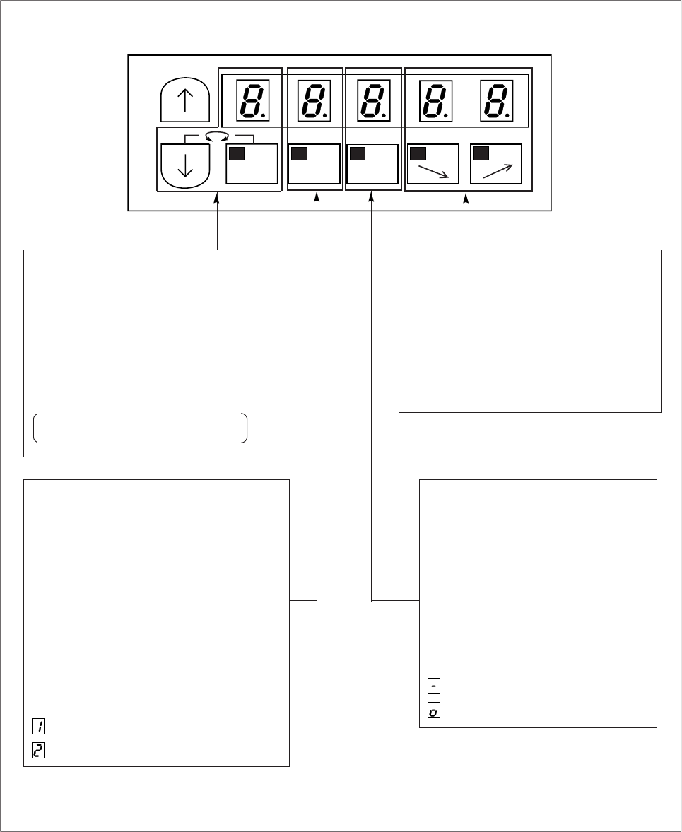
4) How to use the normal mode
Speed adjustment
By operating this [C] key, the speed which
is become late.
By operating this [D] key, the speed when
the pedal is fully toed down is risen.
The rate with speed is 2 digits of LED.C,
LED.D, and is displayed and can be set in
0-99.
Change 1 position / 2 position
By operating this [A] key, 1 position / 2
position can be selected for the needle
position during stopping.
1 position or 2 position is displayed on
LED.A.
At the time of 1 position, the needle is
stopped at Up position.
At the time of 2 position, the needle is
stopped at Down position.
After thread trimming, the needle is
stopped at up position.
is Up position
is Down position
MA
1-2
B
SL
CD
Slow start ON/OFF
By operating this [B] key, slow start
ON/OFF can be selected.
Turned ON when wanting to sew the
beginning of the sewing in slow start.
After the power is turned ON or after
thread trimming, the sewing will start
with a slow start.
Slow start ON/OFF is displayed on
LED.B.
is OFF
is ON
Change motor rotation direction
By operating these two keys ([↓] +
[M]) simultaneously,the rotation
direction of the sewing machine can
be changed.
As for the rotation direction, the
direction which was seen from the
motor axis is displayed in LED.M.
CCW : Counterclockwise rotation
CW : Clockwise rotation
− 28 −
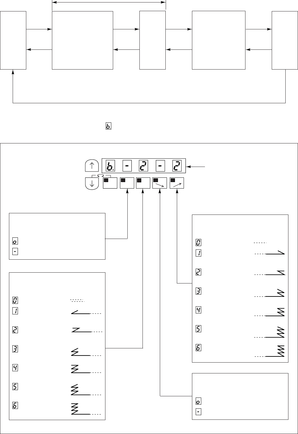
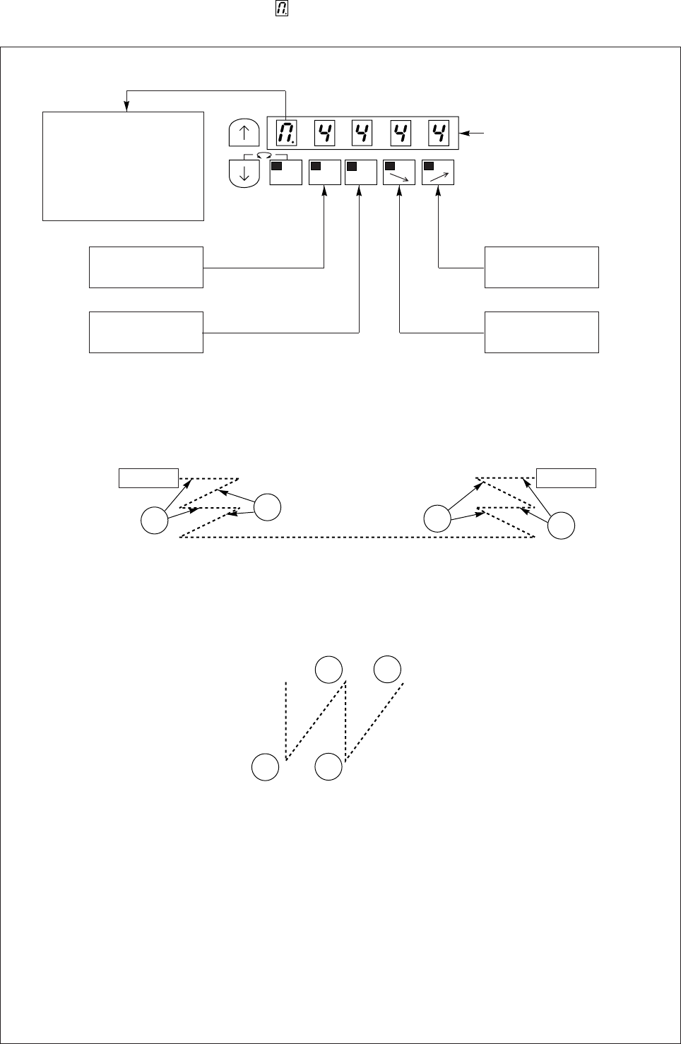
5) Display and function of each key in the tacking mode and pattern mode. (for lock
stitch machine)
(1) Tacking setting mode (At the time of patter No.=4, this mode will be skipped.)
When the [ ↑] key is turned ON, will display above the [M] key, and the tacking setting mode will be
entered. The validity and type of start and tacking can be set here.
Normal
mode
Tacking mode setting
mode
* Setting of the start
tacking validity and
type
* Setting of the end
tacking validity and
type
Tacking mode
No.of
tacking
stitch
setting
mode
Pattern
No.
setting
Preset stitching
setting mode
* Setting of the
presset
stitchingvalidity
and No. of
stitches
[↑] key
ON [↑] key
ON [↑] key
ON [↑] key
ON
[↓] key
ON [↓] key
ON [↓] key
ON [↓] key
ON
Note) At the time of pattern No.=4 (continuous tack), the tacking setting will be skipped.
At the time of pattern No.=A to H (program stitching), the stitching mode will be skipped.
In case of XC-EN, there is no backstitch output. [↑] key ON
MA
1-2
B
SL
CD
Factory setting
Setting of start tacking validity
<Display ex.>
: Valid
: Invalid
Setting of end tacking type
<Display ex.>
: No tacking
: V tacking
(Once tacking)
: N tacking
(Double tacking)
: M tacking
(Triple tacking)
: W tacking
(4 repeat tacking)
: 5 repeat tacking
: 6 repeat tacking
Setting of start tacking type
<Display ex.>
: No tacking
: V tacking
(Once tacking)
: N tacking
(Double tacking)
: M tacking
(Triple tacking)
: W tacking
(4 repeat tacking)
: 5 repeat tacking
: 6 repeat tacking
Setting of end tacking validity
<Display ex.>
: Valid
: Invalid
− 29 −
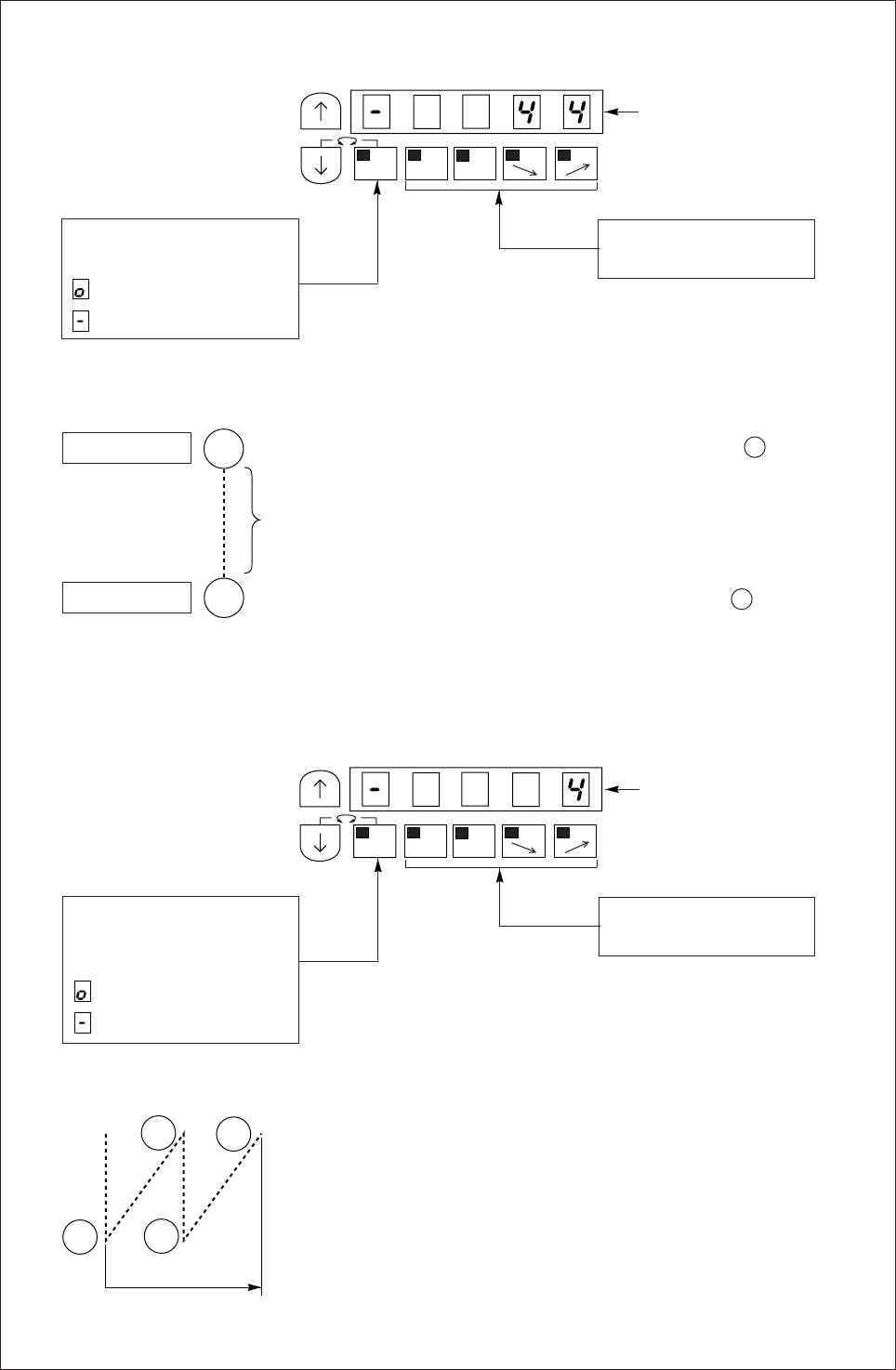
(2) No. of tacking stitches setting mode.
When the [ ↑] key is turned ON again, will display above the [M] key indicator, and the No. of stitches
can be set.
1) The time except pattern No.4
2) When the pattern No.4
Each setting value can be changed from 0 to 9 stitches,A,B,C,D,E,F stitches
A is 10 stitches
B is 11 stitches
C is 12 stitches
D is 13 stitches
E is 14 stitches
F is 15 stitches
MA
1-2
B
SL
CD
Note.
Refer to the “Table of
digital display” for the
correspondence of the
digital display and
alphanumerals.
No. of stitches
A setting.
Factory setting
No. of stitches
B setting.
No. of stitches
D setting.
No. of stitches
C setting.
Start End
ABCD
A
B
C
D
− 30 −
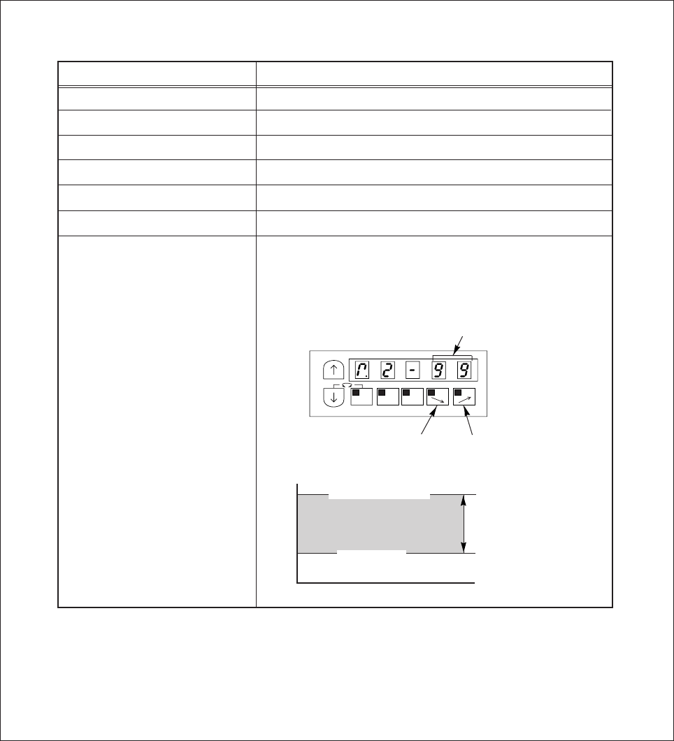
(3) Preset stitching setting mode
1) When the pattern is the time except pattern No.4
In the No.of times (N) setting is N=3, the stitching will be in
the order or A, B and C. If the setting is N=5 , the stitching
will be in the order of A,B,C,D,C. If the N is 6 or more, the
order will be A,B,C,D,C,D…… (If N=0, tacking will continue in
the order ABCDCD…… while the pedal is pressed down.)
2) When the pattern is No.4
MA
1-2
B
SL
CD
Factory setting
Setting of preset stitching
<Display ex.>
: Valid
: Invalid
Setting of No.stitches N
(0 to 9999 stitches)
Start tacking that was in the tacking mode will start at the S position.
End tacking that was in the tacking mode will end at the E position.
Start tacking
End tacking
S
E
N
MA
1-2
B
SL
CD
Factory setting
Setting of continuous tack
stitching validity
<Display ex.>
: Valid
: Invalid
Setting of No. times N
(0 to 9999 stitches)
A
B
C
D
N
− 31 −
10. HOW TO USE THE PROGRAM MODE (EXAMPLE OF MOST
FREQUENTLY USING)
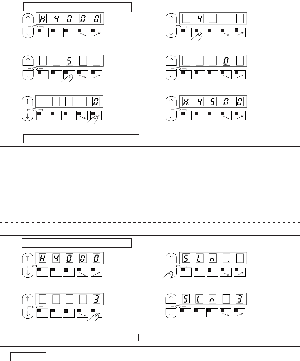
No.1 To change the maximum speed (EX. To change to 4500 rotations)……Function setting [H.4500]
(1) Enter program mode [P] ([ ↓] + [↑])
(2) (3)
* Program mode [P] will be entered. * Set to [4]
(4) (5)
* Set to [5] * Set to [0]
(6) (7)
* Set to [0] * Complete the [H] function setting
(8) Return to the normal mode ([ ↓] + [ ↑])
Description
A. The setting range of the maximum speed is 0 to 8999 rotations.
B. By pressing each of the [A],[B],[C] and [D] keys, the setting value will change between 0 to 9.
(However, the [A] key is only between 0 to 8.)
C. The factory setting is [200 rotations].
D. Low speed,thread trimming speed, start tacking speed, end tacking speed, medium speed and slow
start speed can be set in the same manner.
No.2 To change the number of stitches in slow start (EX. to change three …… Function setting [SLN.3])
(1) Enter program mode [P] ([ ↓] + [↑])
(2) (3)
* Program mode [P] will be entered. * Set function to [SLN]
(4) (5)
* Set to [3] * Complete the [SLN] function setting
(6) Return to the normal mode ([ ↓] + [ ↑])
Description
A. This is valid when the [B] key in the normal mode is turned ON.
B. The setting range of the number of stitches is 1 to 5 stitches.
C. By pressing [D] key, the setting value will change between 1 to 5 stitches.
D. The factory setting is [2 stitches].
MA
1-2
A
SL
CD
MA
1-2
B
SL
CD
MA
1-2
B
SL
CD
MA
1-2
B
SL
CD
MA
1-2
B
SL
CDMA
1-2
B
SL
CD
MA
1-2
A
SL
CDMA
1-2
B
SL
CD
MA
1-2
B
SL
CDMA
1-2
B
SL
CD
− 32 −
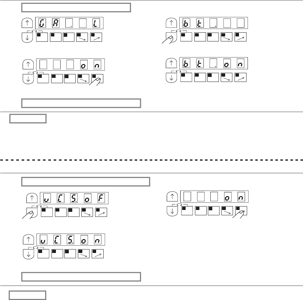
No.3 To apply a weak break during stopping ……function setting[BK.ON]
(1) Enter program mode [A] ([ ↓] + [A])
(2) (3)
* Program mode [A] will be entered. * Set function to [BK]
(4) (5)
* Set to [ON] * Complete the [BK] function setting
(6) Return to the normal mode ([ ↓] + [ ↑])
Description
A. This is used for high speed operation during standing operations.
To turned ON, it operates at the speed with the rate which was set with the [C] and the [D] key in normal
mode regardless of the pedal stepping quantity.
B. This setting is first priority to the key switch [AUTO] of operation panel.
C. The setting value will alternate between [OF] and [ON] with each press of the [D] key in step (3).
(factory setting is [OF])
No.4 To set the standing work type……function setting[VCS.ON]
(1) Enter program mode [ Q ] ([ ↓]+ [ A ] + [ C ])
(2) (3)
* Program mode [Q] will be entered. * Set to [ON]
(4)
* Complete the [VCS.ON] function setting
(5) Return to the normal mode ([ ↓] + [ ↑])
Description
A. Use this when the sewing machine needle is completely down when stopped.
To set ON, motor is applied a weak brake during stopping.
B. The setting value will alternate between [OF] and [ON] with each press of [D] key in step (4).
MA
1-2
B
SL
CD
MA
1-2
B
SL
CD
MA
1-2
B
SL
CDMA
1-2
B
SL
CD
MA
1-2
B
SL
CD
MA
1-2
B
SL
CD
MA
1-2
B
SL
CD
− 33 −
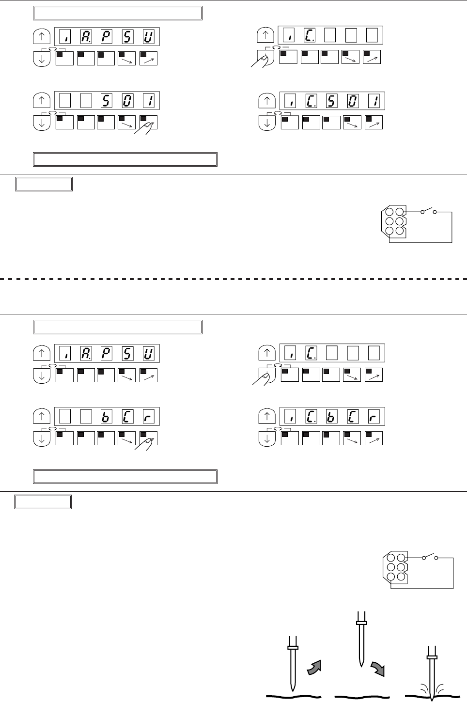
No.5 To change input/output port function.
(1) To operate one stitch operation with a external switch……function setting[IC.S01]
(1) Enter program mode [C] ([ ↓] + [C])
(2) (3)
* Program mode [C] will be entered. * Set function to [IC]
(4) (5)
* Set to [S01] * Complete the [IC] function setting
(6) Return to the normal mode ([ ↓] + [ ↑])
Description
A. This is used to increase the penetration strength of the first stitch when the fabric is thick.
Each time the switch [BCR] connected to the No.6 pin in the option A connector
is turned ON, the (forward) - (reverse) operation will be repeated, and the
needle will stop right with forward operation, above the fabric. However, when
the operation signal is turned ON and the needle is stopped the sewing
machine will operate forward after reversing once.
When stopped with reverse operation, forward operation will start from that
position.
* The needle position stop angle is set with the needle
position stop angle [C8] in the program mode[P]
B. Each time the [D] key is pressed in step (4), the set value
will be changed. (factory setting is [S0])
Note) When using this function, always return to the
normal mode before starting operations.
(2) To confirm the position where the needle passed through the fabricated to raise the penetration
strength of the first stitch with the external switch. ……function setting[IC.BCR]
(1) Enter program mode [C] ([ ↓] + [C])
(2) (3)
* Program mode [C] will be entered. * Set function to [IC]
(4) (5)
* Set to [BCR] * Complete the [IC] function setting
(6) Return to the normal mode ([ ↓] + [ ↑])
Description
A. Using the external switch connected No.6 pin in the option A connector, one
stitch operation will be operated.
B. The setting value will be changed with each press of the [D] key in step (4).
(factory setting is [S0])
Note) When using this function, always return to the normal mode before
starting operations.
MA
1-2
B
SL
CD
MA
1-2
B
SL
CD
MA
1-2
B
SL
CD
MA
1-2
B
SL
CD
MA
1-2
B
SL
CDMA
1-2
B
SL
CD
MA
1-2
B
SL
CDMA
1-2
B
SL
CD
OptionA
0V S1
(IC)
1
2
3
4
5
6
OptionA
0V BCR
(IC)
1
2
3
4
5
6
reverse forward
− 35 −
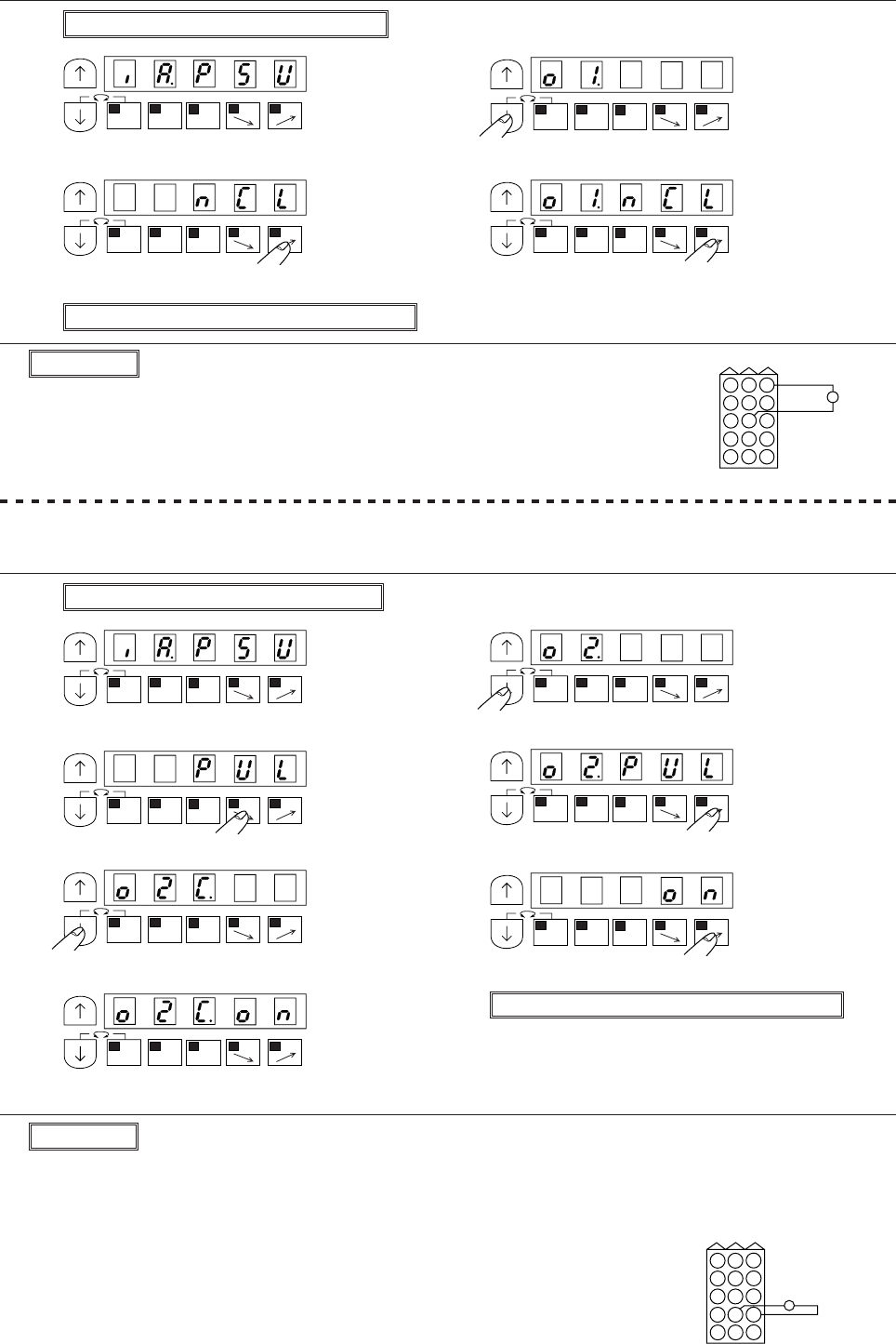
(5) To output a needle cooler output to spare output SOL1 ……function setting [O1.NCL]
(1) Enter program mode [C] ([ ↓] + [C])
(2) (3)
* Program mode [C] will be entered. * Set function to [OI]
(4) (5)
* Set to [NCL] * Complete the [OI] function setting
(6) Return to the normal mode ([ ↓] + [ ↑])
Description
A. Select the puller output [PUL] from the setting table on page 131.
B. Spare output solenoid [SOL2] will be turned on, while presser foot lifter is operated.
(6) To output a puller output to spare output SOL2 ……function setting[O2.PUL] + [O2C.ON] (To set 50
% duty)
(1) Enter program mode [C] ([ ↓] + [C])
(2) (3)
* Program mode [C] will be entered. * Set function to [O2]
(4) (5)
* Set to [PUL] * Complete the [O2] function setting
(6) (7)
* Set function to [O2C] *Set to [ON]
(8) (9) Return to the normal mode ([ ↓] + [ ↑])
*Complete the [O2] founction setting
Description
A. Select the needle cooler output [NCL] from the setting table on page 130.
Select the setting to connect [OI] and [NCL].
B. Spare output [SOL1] will be turned ON while the sewing machine is
running (including needle lifting).
SOL1
MA
1-2
B
SL
CD
MA
1-2
B
SL
CD
MA
1-2
B
SL
CD
MA
1-2
B
SL
CDMA
1-2
B
SL
CD
MA
1-2
B
SL
CD
MA
1-2
B
SL
CDMA
1-2
B
SL
CD
MA
1-2
B
SL
CD
MA
1-2
B
SL
CD
MA
1-2
B
SL
CD
3
6
9
2
5
8
1
4
7
121110
1514
13
Option B
3
6
9
2
5
8
1
4
7
121110
151413
SOL2
Option B
− 36 −
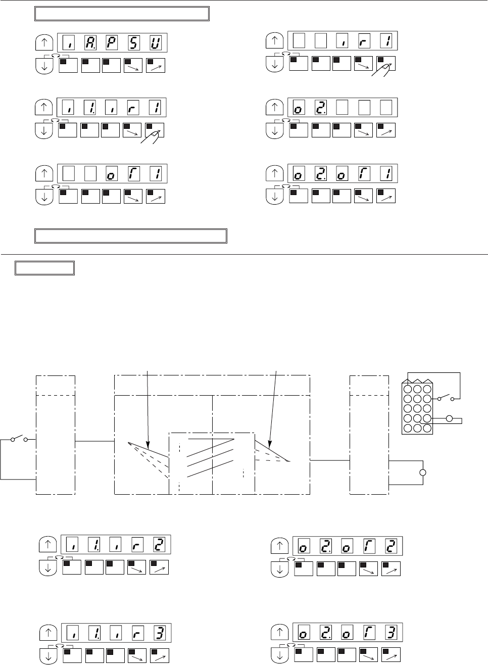
(7) To operate spare output SOL2 only during sewing machine operation using the spare input switch IN1.
..........function setting [I1.IR1] + [O2. OT1]
(1) Enter program mode [C] ([ ↓] + [C])
(2) (3)
* Program mode [C] will be entered. * Set function to [IR1]
(4) (5)
* Set to [I1] * Complete the [O2] function setting
(6) (7)
* Set to [OT1] * Complete the [O2] function setting
(8) Return to the normal mode ([ ↓] + [ ↑])
Description
A. Select the set value[IR1],[IR2] or [IR3] from the setting table on page 128
When [IR1] is selected,[I1] and [IR1] are connected, and [O2] and [OT1] are connected.
When [IR2] is selected,[I1] and [IR2] are connected, and [O2] and [OT2] are connected.
When [IR3] is selected,[I1] and [IR3] are connected, and [O2] and [OT3] are connected.
The example is when [IR1] is selected.
B. The option B connector spare input switch IN1 and spare output SOL2 are connected in the following
manner.
C. The following setting will appear when [IR2] is selected.
(4)’ (7)’
*Connect [I1] to [IR2] * Connect [O2] to [OT2]
D. The following setting will appear when [IR3] is selected.
(4)” (7)”
* Connect[I1] to [IR3] * Connect [O2] to [OT3]
MA
1-2
B
SL
CD
MA
1-2
B
SL
CD
MA
1-2
B
SL
CD
MA
1-2
B
SL
CD
MA
1-2
B
SL
CDMA
1-2
B
SL
CD
MA
1-2
B
SL
CD
MA
1-2
B
SL
CD
MA
1-2
B
SL
CD
MA
1-2
B
SL
CD
0 V
IN1
(IR1)
OUT2 (SOL2)
+30
OptionB
3
6
9
2
5
8
1
4
7
121110
151413
Option B
IN1 Spare
input 1
0 V SOL2
Setting in step (4)
Digital display
I1
I2
IO1
IR1
IR2
IR3
OT1
OT2
OT3
Setting in step (7)
O1
O2
O3
Option B
Spare
output2
30 V
− 37 −
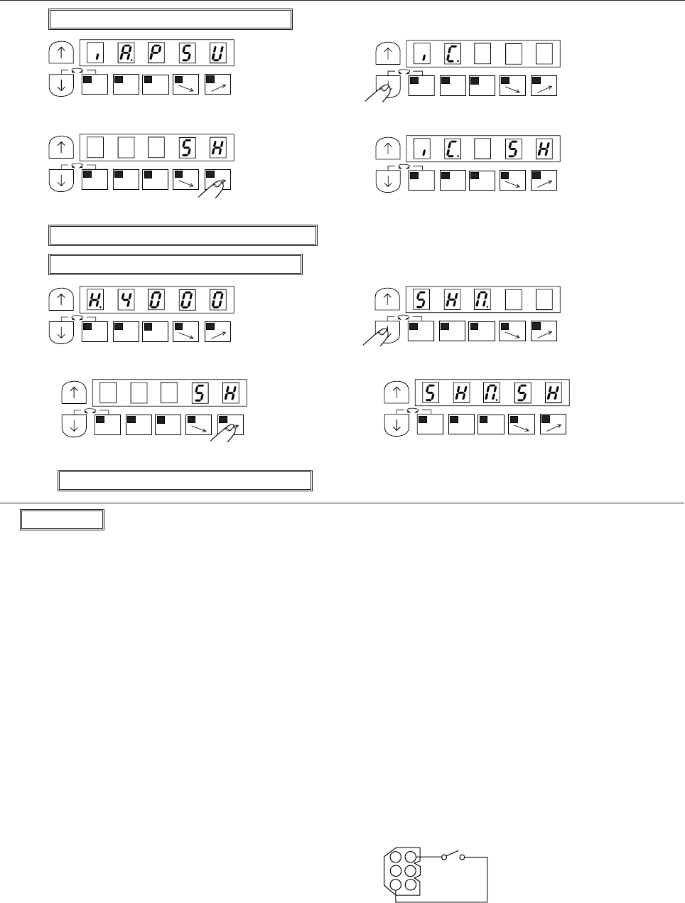
No.6 To set external one shot signal ……function setting C mode [IC.SH] + P mode [SHM.SH]
(1) Enter program mode[C] ([ ↓] + [C])
(2) (3)
* Program mode [C] will be entered. * Set function to [IC]
(4) (5)
*Set to [SH] * Complete the [IC] function setting
(6) Return to the normal mode ([ ↓] + [ ↑])
(7) Enter program mode [P] ([ ↓] + [↑])
(8) (9)
* Program mode [P] will be entered. * Set function to [SHM]
(10) (11)
* Set to [SH] * Complete the [SHM] function setting
(12) Return the normal mode ([ ↓] + [ ↑])
MA
1-2
B
SL
CD
MA
1-2
B
SL
CD
Description
A. Set both C mode [IC] and P mode [SHM] function.
B. When external one shot signal [SH] (connected No.6 pin in option connector A) is turned ON.automatic
sewing is operated. And when [SH] signal is turned OFF, manual sewing can be operated.
* When one shot signal ON and then either of external operation signals (S0,S1,S4) is turned ON, the
sewing machine will be operate at each order speed. And external operation signal is turned OFF,
sewing machine will be operate at the speed set by [C],[D] key.
(When [P] mode [AT]=ON or control panel key is ON,operation can be stopped by PSU,PSD or ES
signals.)
C. Each time the [D] key is pressed in step (4), the set value will be changed.
D. Each time the [D] key is pressed in step (10), the set value will be changed. (factory setting is [SH])
* Set[SS] setting,the operation will be become same as No.13.
Note) When using this function, always return to the normal mode before starting operations.
MA
1-2
B
SL
CD
MA
1-2
B
SL
CD
MA
1-2
B
SL
CD
MA
1-2
B
SL
CD
MA
1-2
B
SL
CD
MA
1-2
B
SL
CD
SH
1
2
3
4
5
6
Option A
0 V
− 38 −
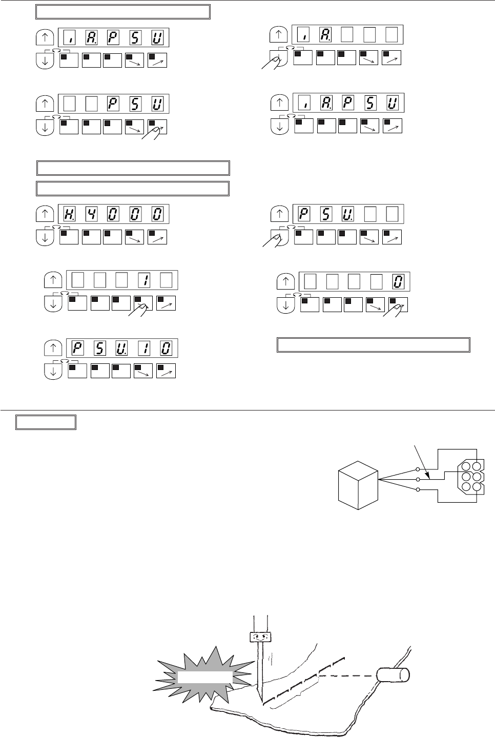
No.7 To set number of stitches to the needle UP position stop after detecting the fabric end with an optical
sensor, etc. (Ex. to set to 10 stitches)……function setting C mode [IA.PSU] + P mode [PSU.10]
(1) Enter program mode[C] ([ ↓] + [C])
(2) (3)
* Program mode [C] will be entered. * Set function to [IA]
(4) (5)
* Set to [PSU] * Complete the [IA] function setting
(6) Return to the normal mode ([ ↓] + [ ↑])
(7) Enter program mode [P] ([ ↓] + [ ↑])
(8) (9)
* Program mode [P] will be entered. * Set function to [PSU]
(10) (11)
* Set to [1] * Set to [0]
(12) (13) Return the normal mode ([ ↓] + [ ↑])
* Complete the [PSU] function setting
Description
A. Set both C mode [IA] and P mode [PSU] function.
B. Connect photoelectric sensor to No.2 pin in option A connector,
and photoelectric sensor is turned ON, the needle will stop at
the UP position after 10 stitches and then the thread will be
trimmed.
C. Each time the [D] key is pressed in step (4), the set value will be
changed.(factory setting is [PSU])
D. The setting range of the number of stitches in 0 to 99 stitches.
E. Each time the [C] key in step (10) or [D] key in step (11) is pressed, the set value will change between 0 to 9.
F. Set function [IB.PSU] + [PSU.10], it is possible to set number of stitches after detecting the fabric end
with an optical sensor. (Connect optical sensor output to No.4 pin in option connector A.)
(* for example, use the optical sensor in OMRON E3V3-D62)
MA
1-2
B
SL
CD
MA
1-2
B
SL
CD
MA
1-2
B
SL
CD
MA
1-2
B
SL
CD
MA
1-2
B
SL
CD
MA
1-2
B
SL
CD
MA
1-2
B
SL
CD
MA
1-2
B
SL
CD
MA
1-2
B
SL
CD
Sensor detection point
Setting of No.
of stitches
Needle stop
1
2
3
4
5
6
Signal write 0 V
Power
supply
+12V
Optical
sensor
Option A
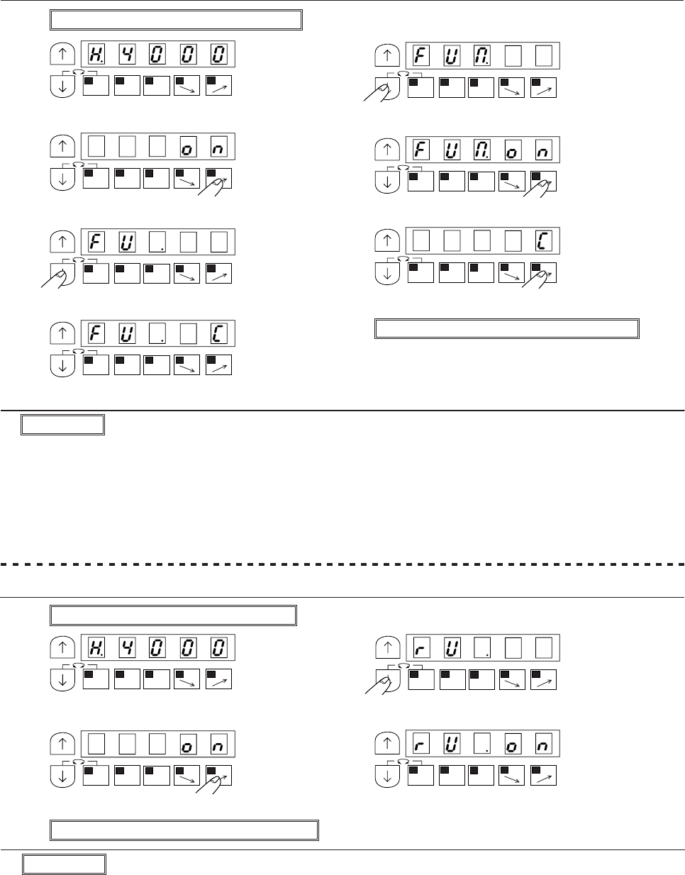
− 39 −
No.8 To continue presser foot lifting after the thread trimming, and to bring down the presser foot after
the time set on the timer has passed. …… function setting [FUM.ON] + [FU.C]
(1) Enter program mode [P] ([ ↓] + [↑])
(2) (3)
* Program mode [P] will be entered. * Set function to [FUM]
(4) (5)
* Set to [ON] * Complete the [FUM] function setting
(6) (7)
* Press [ ↓] key and set function [FU] * Set to [C]
(8) (9) Return to the normal mode ([ ↓] +[ ↑])
* Complete the [FU] function setting
Description
A. The motor is reverse run after thread trimming, and the needle will stop near the needle bar top dead
point.
The reverse run angle can be set in [R8] and the setting range is 0 to 360, and it is 2-degree interval.
B. The setting value will alternate between [OF] and [ON] with each press of [D] key in (4). (factory setting
is [OF])
No.9 To set needle position higher than usual after thread trimming …… function setting [RU.ON]
(1) Enter program mode [P] ( ↓] + [ ↑])
(2) (3)
* Program mode [P] will be entered. * Set function to [RU]
(4) (5)
* Set to [ON] * Complete the [RU] function setting
(6) Return to the normal mode ([ ↓] + [ ↑])
Description
A. Set both [FUM] and [FU] functions.
B. Each time of the [D] key is pressed in step (4), the se value will alternate between [OF] and [ON]. (factory
setting is [OF])
C. Each time the [D] key is pressed in step (7), the set value will change in order of [M][C][A][T]. (factory
setting is [M])
D. The timer time can be adjusted with the FUM timer setting[FCT] in the [C] mode. (factory setting is 12 sec)
MA
1-2
B
SL
CD
MA
1-2
B
SL
CD
MA
1-2
B
SL
CD
MA
1-2
B
SL
CD
MA
1-2
B
SL
CD
MA
1-2
B
SL
CD
MA
1-2
B
SL
CD
MA
1-2
B
SL
CD
MA
1-2
B
SL
CD
MA
1-2
B
SL
CD
MA
1-2
B
SL
CD
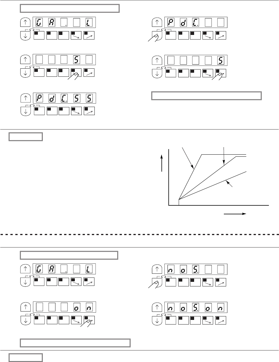
− 40 −
No.10 To adjust the correlation between toe down angle speed. (EX. to set value 55 to sew quickly at a
high speed)……function setting [PDC.55]
(1) Enter program mode [A] ([ ↓] + [A])
(2) (3)
* Program mode [A] will be entered. * Set function to [PDC]
(4) (5)
* Set to [5] * Set to [5]
(6) (7) Return to the normal mode ([ ↓] + [ ↑])
* Complete the [PDC] function setting
Description
A. Only variable-speed operation will be possible. Set position stopping and thread trimming will not be
possible.
B. Each time the [D] key is pressed, the setting will alternate between [OF] and [ON]
No.11 To run without the detector (when the detector is broken). ……function setting[NOS.ON]
(1) Enter program mode [A] ([ ↓] + [A])
(2) (3)
* Program mode [A] will be entered. * Set function to [NOS]
(4) (5)
* Set to [ON] * Complete the [NOS] function setting
(6) Return to the normal mode ([ ↓] + [ ↑])
Description
A. The curve amount of the speed change for the
amount that.
The curve amount of the speed change for the size
of the set value can be set. The pedal is pressed
can be set. To sew quickly at a high speed, increase
the set value. To finely adjust the medium speed
region, decrease the setting.
B. The setting range is 10 to 99. (factory setting is [30])
C. Each time the [C] key in step (4) or [D] key in step
(5) is pressed, the set value will change between 0
to 9. (However, the [C] key is between 1 to 9)
MA
1-2
B
SL
CD
MA
1-2
B
SL
CDMA
1-2
B
SL
CD
MA
1-2
B
SL
CD
MA
1-2
B
SL
CD
MA
1-2
B
SL
CD
MA
1-2
B
SL
CD
MA
1-2
B
SL
CD
MA
1-2
B
SL
CD
Speed Set value-Large Factory setting [30]
Set value-Small
Pedal toe down
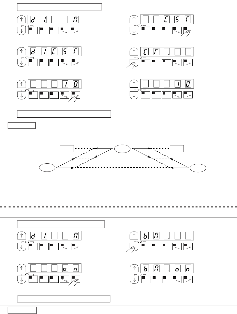
− 41 −
No.12 To adjust tacking accurately
(1) To adjust tacking surely ……[D1.CST] + [CT.10]
(To set the stop time at each tacking corner to 100 milliseconds)
(1) Enter program mode [D] ([ ↓] + [D])
(2) (3)
* Program mode [D] will be entered. * Set function to [CST]
(4) (5)
* Complete the [D1] function setting * Set function to [CT]
(6) (7)
* Set to [I0] * Complete the [CT] function setting
(8) Return to the normal mode ([ ↓] + [ ↑])
Description
A. Set function [BM] to [ON] when start/end tacking speed is less than 1000 rpm
B. Set function [BM] to [OF] when start/end tacking speed is 1000 rpm or higher.
This BM function can be used for a rough tacking alignment of the start and end tacking.
C. Each time the [D] key is pressed, the setting will alternate between [OF] and [ON]. (The factory setting
is [OF].)
Note) This function can be used when a stop is not made at each corner when tacking.
When the function setting [D1.CST] is set, this function setting [BM.ON] will be invalidated.
(2) To align tacking when start/end tacking speed is less than 1000 rpm. ……function setting [BM.ON]
(1) Enter program mode [D] ([ ↓] + [ D ])
(2) (3)
* Program mode [D] will entered. * Set function to [BM]
(4) (5)
* Set to [ON] * Complete the [BM] function setting
(6) Return to the normal mode ([ ↓] + [ ↑])
Description
A. Set the type of start/end tacking and the no.of stitches before making the above setting.
B. For example, to carry out W tacking, the unit will stop at each corner for 100 milliseconds.
C. Each time the [D] key is pressed in step (3), the setting will change in the order of [M], [D], [CST], [CSU]
and [CSD]. (factory setting is [M])
D. The setting range of the stop time is 0 to 990 milliseconds in 10-millisecond intervals.
E. Each time the [C] key is pressed in the step (6), the set value will change from 0 to 9, and each time the
[D] key is pressed, will change from 0 to 9.
MA
1-2
B
SL
CD
MA
1-2
B
SL
CD
MA
1-2
B
SL
CD
MA
1-2
B
SL
CD
MA
1-2
B
SL
CDMA
1-2
B
SL
CD
MA
1-2
B
SL
CDMA
1-2
B
SL
CD
MA
1-2
B
SL
CD
MA
1-2
B
SL
CD
Start End
Stop Stop
Stop
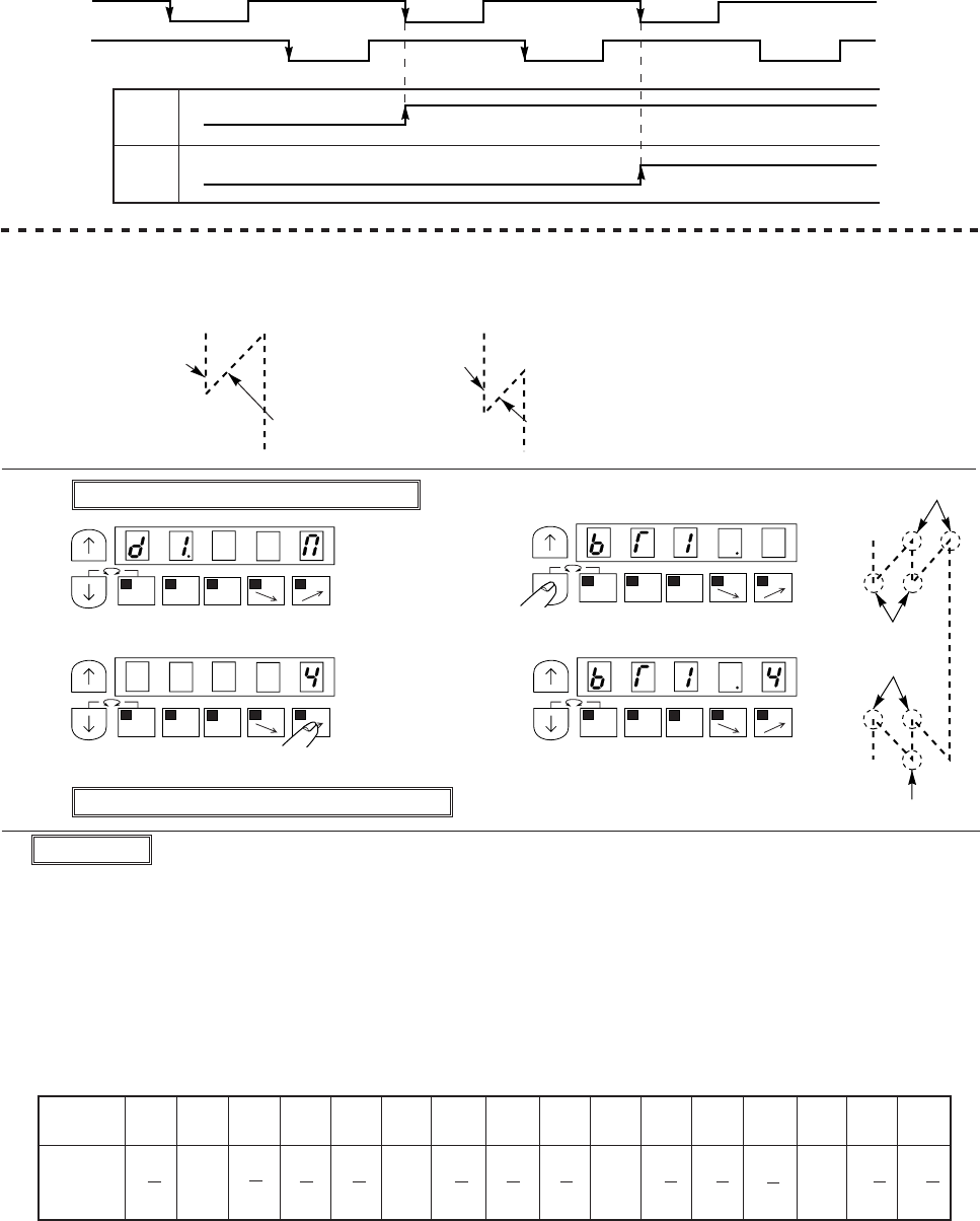
− 42 −
D. Set to the tack alignment
When “BM” is OFF, the timing of backstitch solenoid turning ON is one stitch before the setting number
stitches. (as shown below.)
When “BM” is ON, the timing of backstitch solenoid turning ON is the setting number stitches.
(3) To set the no. of stitch compensation for start tacking alignment BT1
(To correct the no. of advance stitches during start tacking) …… Function setting [BT1.4]
(Note) This no.of stitch correction
can be used when a stop is
not made at each corner
when tacking.
Description
A. In the above example, the four stitches art used for the start tack advance. This is one stitch more than
the no. of stitches set in the start tack setting, so reset it so that it is shorter. Set the no. of correction
stitches to –1. The relation of the no. of correction stitches and setting value is shown below. Set the
setting value to [4].
B. With this setting, the advance section will be one stitch sorter, and the retract section will be increased
by one stitch to three stitches. The no.of stitches will be as set.
C. Each time the [D] key is pressed, the setting will change in order from 0 to 9,A,B,C,D,E,and F.
D. The relation of the no. of correction stitches and setting value is as shown below.
E. The no.of correction stitches set in BT1 is common for the start tack, V tack, M tack, and W tack.
F. The no.of stitches can be corrected easily by using this function and the start tack speed change.
Note : 1. When the function setting[D1.CST] is to adjust taking surely, this fumction setting [BT1.*]
will be invalidated.
2. The setting of “BT2” “BT3” and “BT4” is as same as “BT1”.
The backstitch solenoid operation timing BM
UP
DN
N-2 N-1 N
OFF
ON
(1) Enter program mode [D] ([ ↓] + [D])
(2) (3)
* Program mode [D] will be entered. * Set function to [BT1]
(4) (5)
* Set to [4] * Complete the [BT1] function setting
(6) Return to the normal mode ([ ↓] + [ ↑])
(Ex.) No.of start tacking set stitches Actual no.of stitches
3 stitches
3 stitches
4 stitches
2 stitches
Setting
value
No.of
correction
stitches
9876543210ABCDEF
-2 -1 1
1
4
-2 3
4
-1 2
4
-1 1
4
-1 3
4
-2
4
-1
4
-1
4
+2
4
+3
4
+1
4
+1 2
4
+1
0
MA
1-2
B
SL
CD
MA
1-2
B
SL
CD
MA
1-2
B
SL
CDMA
1-2
B
SL
CD
BT2
BT1
BT3
BT4
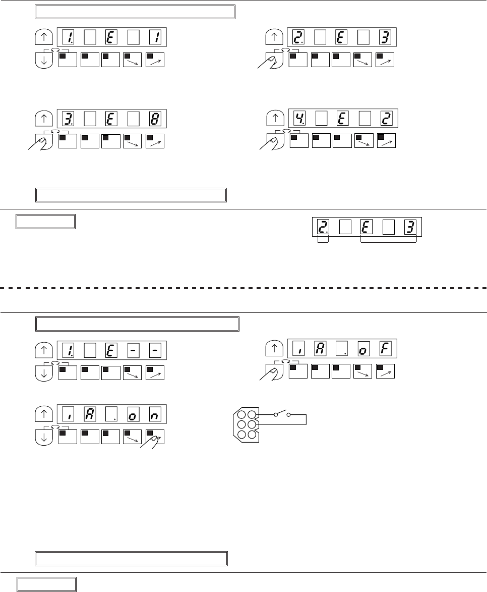
− 43 −
No.13 To check the error code history and input/output signal
(1) How to view the error code history … ……function setting [1.E--], [2.E--], [3.E--], [4.E--]
(1) Enter program mode [E] ([ ↓] + [↑] +[A])
(2) (3)
* The last error code is displayed. * The second to last error code is displayed.
(Ex. error code E1 is displayed.) (Ex. error code E3 is displayed.)
(4) (5)
* The third to last error code is displayed. * The fourth to last error code is displayed.
(Ex. error code E8 is displayed.) (Ex. error code E2 is displayed.)
(6) Return to the normal mode ([ ↓] + [ ↑])
Description
A. It is possible to check whether or not input signal is wired right.
When the display doesn’t [ON] even if it turned ON a signal, check wiring to a control box from the
signal.
B. The input terminal refer to the explanation of the input/output signal and input function name refer to a
C mode input signal setting table.
(2) To check input signals ……function setting [IA] – [IP], [I1] – [I7], [UP], [DN], [ECA], [ECB]
(1) Enter program mode [E] ([ ↓] + [↑] + [A])
(2) (3)
* Program mode [E] will be entered. * Select input function to see
(4)
* If the display changes from [OF] to [ON] when the input signal is turned ON, the operation is normal.
(This example is checking input signal [IA])
When to check the signals of [UP], [DN], rotate sewing machine shaft and to check the signal of [ECA],
[ECB], rotate motor shaft.
(Caution) Be careful to sewing machine operation when turned ON the signal which the sewing
machine operation has relation.
(5) Return to the normal mode ([ ↓] + [ ↑])
Description
A. The last to fourth to last errors can be viewed.
B. Refer to page 140 for the error code.
C. The display is as in the right figure.
Error code number
MA
1-2
B
SL
CD
MA
1-2
A
SL
CD
MA
1-2
B
SL
CDMA
1-2
B
SL
CD
MA
1-2
B
SL
CD
MA
1-2
B
SL
CD
MA
1-2
B
SL
CD
The record
number of
times
1
2
3
4
5
6
Option
0V IA
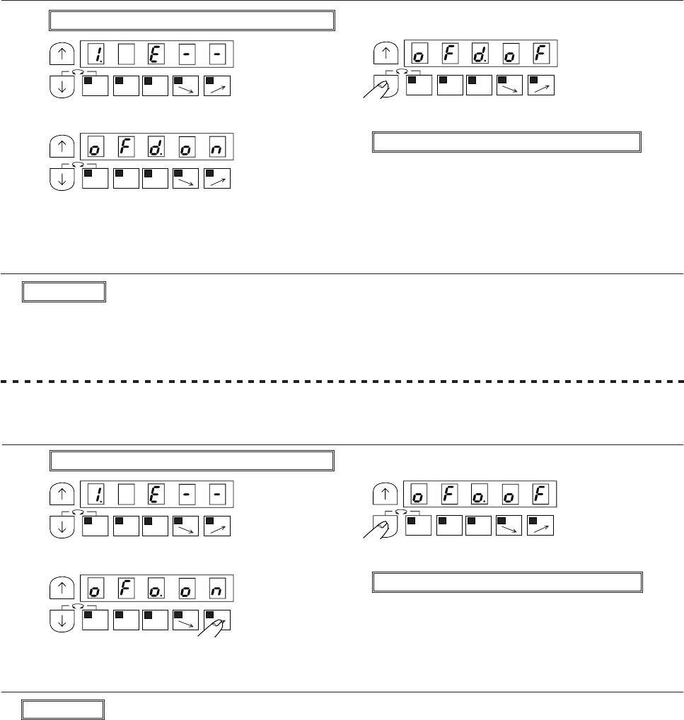
− 44 −
(3) To check output signal (check in operation)……function setting [OAD]-[OFD], [O1D]-[O7D]
(1) Enter program mode [E] ([ ↓] + [ ↑] + [A])
(2) (3)
* Program mode [E] will be entered. * Select output function to see
(4) (5) Return to the normal mode ([ ↓] + [ ↑])
* Operate that the output terminal turned ON and check display is turned [ON]
(Caution) Be careful to sewing machine operation when turned ON the signal which the sewing
machine operation has relation.
Description
A. It is useful function for check a wiring.
B. The input terminal refer to the explanation of the input/output signal and input function name refer to a
C mode input signal setting table.
(4) To check an output terminal
(It is turned ON an output terminal without sewing machine operation ……function setting [OAO]-
[OFO], [O1O]-[O7O])
(1) Enter program mode [E] ([ ↓] + [ ↑] + [A])
(2) (3)
* Program mode [E] will be entered. * Select output function to see
(4) (5) Return to the normal mode ([ ↓] + [ ↑])
Output signal is turned ON while pressing the [D] key.
Note) While displaying this function, sewing machine can not operate.
Description
A. It is useful function for check a operation before wiring solenoid.
B. The input terminal refer to the explanation of the input/output signal and input function name refer to a
C mode input signal setting table.
MA
1-2
B
SL
CD
MA
1-2
B
SL
CD
MA
1-2
B
SL
CD
MA
1-2
B
SL
CD
MA
1-2
B
SL
CD
MA
1-2
B
SL
CD
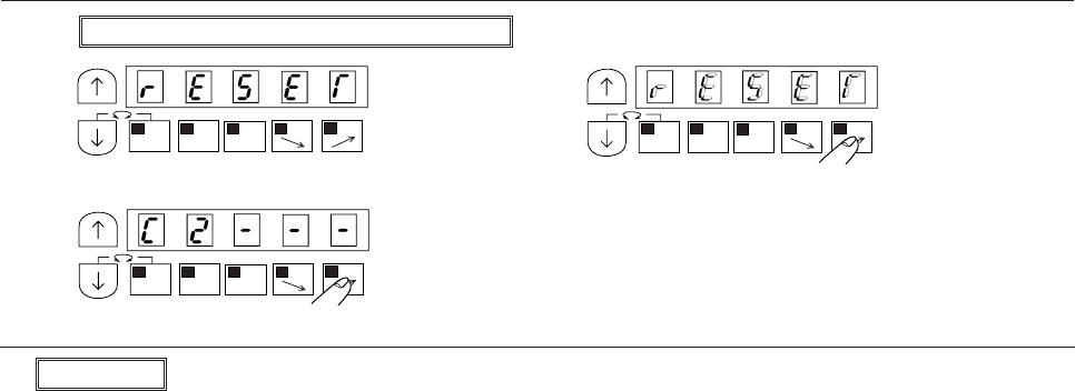
− 45 −
No.14 To return all setting to the factory settings ……function setting [RESET]
(1) Enter program mode [R] ([ ↓] + [B] + [C])
(2) (3)
* Program mode [R] will be entered. * [RESET] will flicker when the [D] key is pressed.
(4)
* When the [D] key is held down (for two seconds), all settings will be returned to the factory settings.
Description
A. When the normal mode will be entered pressing the [D] key when displayed [RESET], all settings will be
returned to the factory settings.
B. To return the normal mode from the [RESET], press the [ ↓] key while holding down the [ ↑] key.
(Caution) When this function is set, the contents of all settings to this point will be cleared, and will
return to the factory settings. Please take care when using this function.
MA
1-2
B
SL
CD
MA
1-2
B
SL
CD
MA
1-2
B
SL
CD
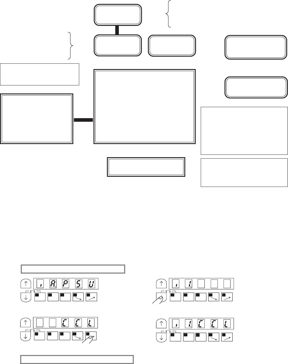
− 46 −
11. HOW TO SET COUNTER FUNCTION
1. To use the counter function
(1) The outline of the counter function
By setting a counter function which is shown in the following figure, it is possible to do the operation to want.
[P] key function selection
[C] mode [IP] = [CCL] : Clear counter
(counter with control panel [P] key
clearness)
(2) Example for counter function
* The counting product amount and bobbin thread are enabled with up and down counter.
1 UP counter for product amount (one hundred times)
(1) Up counter “U” is add at each thread trimming.
(2) When up counter amount “U” become the setting amount “P”, sewing will be prohibited.
(3) When the input signal “I1” is turned on, Up counter amount become zero and sewing become
possible.
(1) Enter program mode “C” ([ ↓] + [C])
(2) (3)
* Program mode [C] will entered. * Set function to [I1]
(4) (5)
* Set to [CCL] * Complete the [I1] function setting
(6) Return to the normal mode ([ ↓] + [ ↑])
Count by
* Thread trimming (CU, PR)
* Number of stitch (ST)
* External input signal (IN)
* External output signal (OU)
Selection
The action after
count over
Counting
condition Counter clear
condition
Selection Set of the [USC], [DSC]
Buzzer sound and sewing will be prohibited (ST)
Buzzer sound and sewing is available (BZ)
No buzzer sound and sewing is available (OF)
The case :
Changing sewing pattern.
Turning on power switch.
[UCM], [DCM], [PCM]
Example
: UP counter for production
counter
: Down counter for remain
bobbin thread counter.
(Please refer the example
on page 81.)
Counter function
UP counter valid : [UPC]=[ON]
DOWN counter valid : [DNC]=[ON]
To use the control panel
(XC-E500Y)
[C] mode [CNF] setting ([F] key
display)
[CNF]=[DN] : DOWN counter display
[CNF]=[UP] : UP counter display
([CNF]=[SP] : Speed display)
([CNF]=[SE] : Sensor needle numeric
display)
Adjustment of counter amount
to use input signal
Counter value setting
UP counter value : [P]=[****]
DOWN counter value : [N]=[****]
MA
1-2
B
SL
CDMA
1-2
B
SL
CD
MA
1-2
B
SL
CD
MA
1-2
B
SL
CD
a
a
a
a
a
a
a
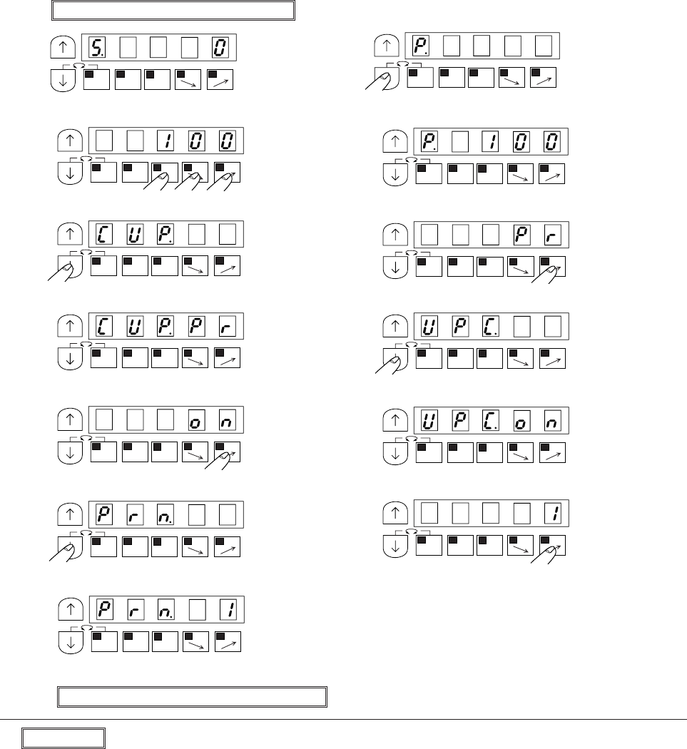
− 47 −
(7) Enter program mode “B” ([ ↓] + [B])
(8) (9)
* Program mode [B] will be entered. * Set function to [P]
(10) (11)
* Set to [100] * Complete the [P] function setting
(12) (13)
* Set function to [CUP] * Set to [PR]
(14) (15)
* Complete the [CUP] function setting * Set function to [UPC]
(16) (17)
* Set to [ON] * Complete the [UPC] function setting
(18) (19)
* Set function to [PRN] * Set to [1]
(20)
* Complete the [PRN] function setting
(21) Return to the normal mode ([ ↓] + [ ↑])
Description
Selection the function on program mode “C”.
[I1,CCL] : Input signal “I1” is set to counter clear function.
Selection the function on program mode “B”.
[P.100] Set the setting amount of up counter “P”. This amount become the target amount for up counter.
* [U.0] Current up counter amount “0”
[CUP.PR] : ”PRN” function is that up counter is added at each trimming time.
(”PRN” is set “1”, up counter is added each trimming time in this example)
* [USC.ST] : When the amount of current up counter “U” become setting amount “P”, sewing will be
prohibited
Input signal “I1” is set to the following function. When it is turned on, sewing become
possible.
[UPC.ON] Set “UPC” to “ON” to use up counter.
[PRN.1] one trimming time add one count amount.
Mark “ * ” is factory setting.
MA
1-2
B
SL
CD
MA
1-2
B
SL
CD
MA
1-2
B
SL
CD
MA
1-2
B
SL
CD
MA
1-2
B
SL
CD
MA
1-2
B
SL
CDMA
1-2
B
SL
CD
MA
1-2
B
SL
CD
MA
1-2
B
SL
CD
MA
1-2
B
SL
CD
MA
1-2
B
SL
CDMA
1-2
B
SL
CD
MA
1-2
B
SL
CD
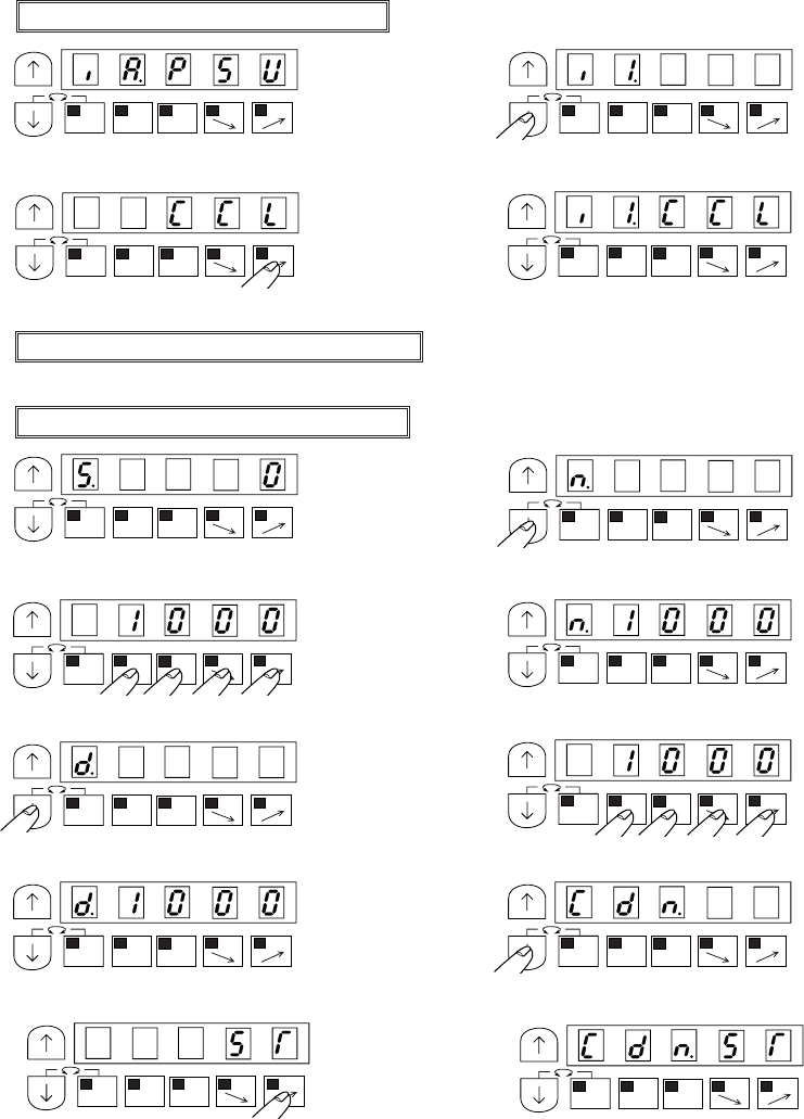
− 48 −
2. Down counter for bobbin remain thread count (10,000 stitches is count over)
[1] Down counter “D” is subtracted at each ten stitches.
[2] When down counter amount “D” become zero, sewing will be prohibited.
[3] When the input signal “I1” is turned on, Down counter amount become “N” stitch and sewing become
possible.
(1) Enter program mode “C” ([ ↓] + [C])
(2) (3)
* Program mode “C” will be entered. * Set to “I1”ÅiInput signalÅj
(4) (5)
* Set to “CCL” (Input function) * Complete the “I1” function setting.
(6) Return to the normal mode ([ ↓] + [ ↑])
(1) Enter to program mode “B” ([ ↓] + [B])
(2) (3)
* Program mode “B” will be entered. * Set to “N”
(4) (5)
* Set to “1000” * Complete the “N” function setting.
(6) (7)
* Set to “D” * Set to “1000”
(8) (9)
* Complete the “N” function setting * Set to “CDN”
(10) (11)
* Set to “ST” * Complete the “CDN” function setting
MA
1-2
B
SL
CDMA
1-2
B
SL
CD
MA
1-2
B
SL
CD
MA
1-2
B
SL
CD
MA
1-2
B
SL
CD
MA
1-2
B
SL
CD
MA
1-2
B
SL
CD
MA
1-2
B
SL
CD
MA
1-2
B
SL
CD
MA
1-2
B
SL
CDMA
1-2
B
SL
CD
MA
1-2
B
SL
CD
MA
1-2
B
SL
CD
MA
1-2
B
SL
CD
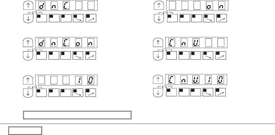
− 49 −
(12) (13)
* Set to “DNC” * Set to “ON”
(14) (15)
* Complete the “DNC” function setting * Set to “CNU”
(16) (17)
* Set to “10” * Complete the “CNU” function setting
(18) Return to the normal mode ([ ↓] + [ ↑])
Description
Selection the function on program mode “C”.
[I1,CCL] : Input signal “I1” is set to counter clear function.
Selection the function on program mode “B”.
[N.1000] Set the setting amount of up counter “N”. This amount is start amount of down count.
[CDN.ST] : When stitch amount become the amount set by “CNU”, down counter “D” is subtracted one.
(”CNU” is set “10”, so down counter is subtracted at each ten stitches in this example)
* [DSC.ST] : When the amount of current down counter become zero, sewing will be prohibited Input
signal “I1” is set to the following function. When it is turned on, sewing become possible.
[DNC.ON] Set “DNC” to “ON” to use down counter.
[CNU.10] Ten stitches subtract one count amount.
Mark “ * ” is factory setting.
MA
1-2
B
SL
CD
MA
1-2
B
SL
CD
MA
1-2
B
SL
CDMA
1-2
B
SL
CD
MA
1-2
B
SL
CD
MA
1-2
B
SL
CD
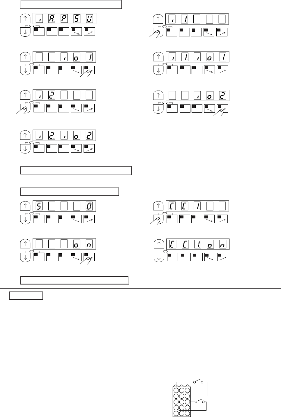
− 50 −
3. How to Adjust current count amount to use input signal.
(1) Enter program mode “C” ([ ↓] + [C])
(2) (3)
* Program mode “C” will be entered. * Set to “I1” (Input signal)
(4) (5)
* Set to “IO1” * Complete the “I1” function setting
(6) (7)
* Set to “I2” (Input signal) * Set to “IO2”
(8)
* Complete the “I2” function setting
(9) Return to the normal mode ([ ↓] + [ ↑])
(1) Enter program mode “B” ([ ↓] + [B])
(2) (3)
* Program mode “B” will be entered. * Set to “CCI”
(4) (5)
* Set to “ON” * Complete the “CCI” function setting.
(6) Return to the normal mode ([ ↓] + [ ↑])
Description
Selection the function on program mode “C”.
[I1.IO1] Input signal “I1” is set to “IO1” function.
[I2.IO2] Input signal “I2” is set to “IO2” function.
Selection the function on program mode “B”.
[CCL.ON] When input signal “I1” is turned on both counter will be added one amount.
[CCL.ON] When input signal “I2” is turned on both counter will be subtracted one amount.
MA
1-2
B
SL
CD
MA
1-2
B
SL
CD
MA
1-2
B
SL
CD
MA
1-2
B
SL
CD
MA
1-2
B
SL
CD
MA
1-2
B
SL
CD
MA
1-2
B
SL
CD
MA
1-2
B
SL
CD
MA
1-2
B
SL
CD
MA
1-2
B
SL
CD
MA
1-2
B
SL
CD
3
6
9
2
5
8
1
4
7
1211
10
151413
Option B counter
Input signal
I1
Input signal
I2
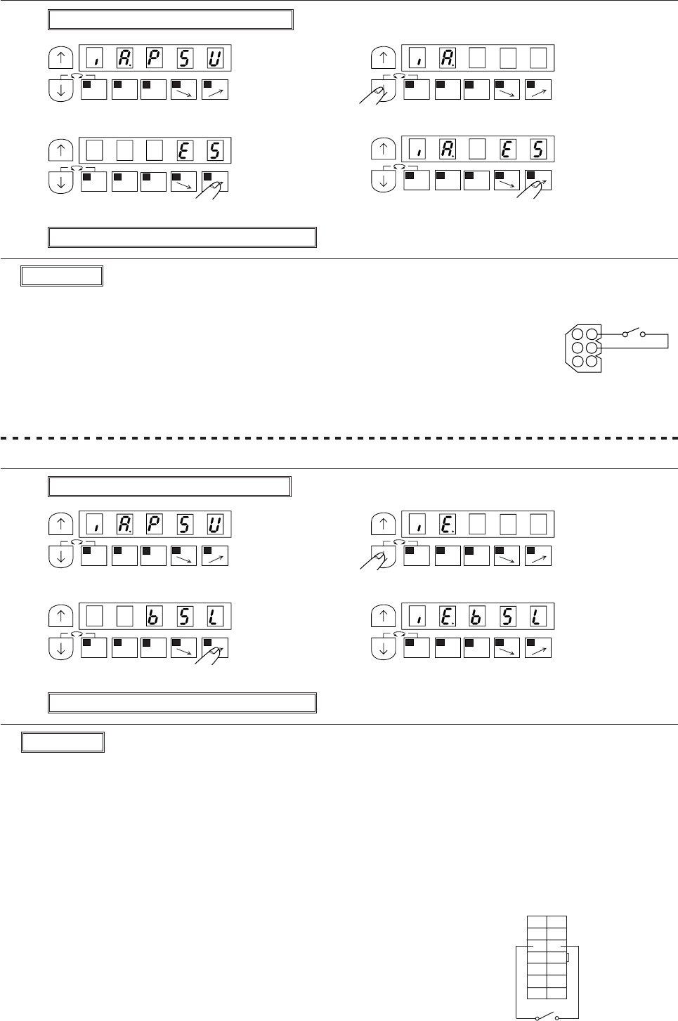
− 34 −
MA
1-2
B
SL
CD
(3) To emergency stop during sewing machine operation …… function setting[IA.ES]
(1) Enter program mode [C] ([ ↓] + [C])
(2) (3)
* Program mode [C] will be entered. * Set function to [IA]
(4) (5)
* Set to [ES] * Complete the [IA] function setting
(6) Return to the normal mode ([ ↓] + [ ↑])
Description
A. Turning ON the external switch connected No.5 pin in sewing machine connector, backtacking output
will be operate when sewing machine is stopped.
When beginning to sew by backstitching,the operation becomes smooth.
B. The setting value will be changed with each press of [D] key in step (4).
(factory setting is [S7])
Note) When using this function, always return to the normal mode before starting operations.
(4) To operate backstitching signal during sewing machine is stopped. ……function setting [IE.BSL]
(1) Enter program mode [C] ([ ↓] + [C])
(2) (3)
* Program mode [C] will be entered. * Set function to [IE]
(4) (5)
* Set to [BSL] * Complete the [IE] function setting
(6) Return to the normal mode ([ ↓] + [ ↑])
Description
A. The switch connected No.2 pin in the option A connector is emergency stop signal.
B. The setting value will be changed with each press of the [D] key in step (4).
(factory setting is [PSU])
C. Setting function [ID.ES], It becomes the function of emergency stop signal too.
(Connect the external switch No.5-No.6 pin in the sewing machine connector.)
Note) When using this function, always return to the normal mode before starting operations.
MA
1-2
B
SL
CD
MA
1-2
B
SL
CD
MA
1-2
B
SL
CD
MA
1-2
A
SL
CD
MA
1-2
B
SL
CD
MA
1-2
B
SL
CD
MA
1-2
B
SL
CD
1
2
3
4
5
6
Option A
0V ES
(IA)
Sewing machine
BSL 0V
7
6
5
4
3
2
1
!4
!3
!2
!1
!0
9
8
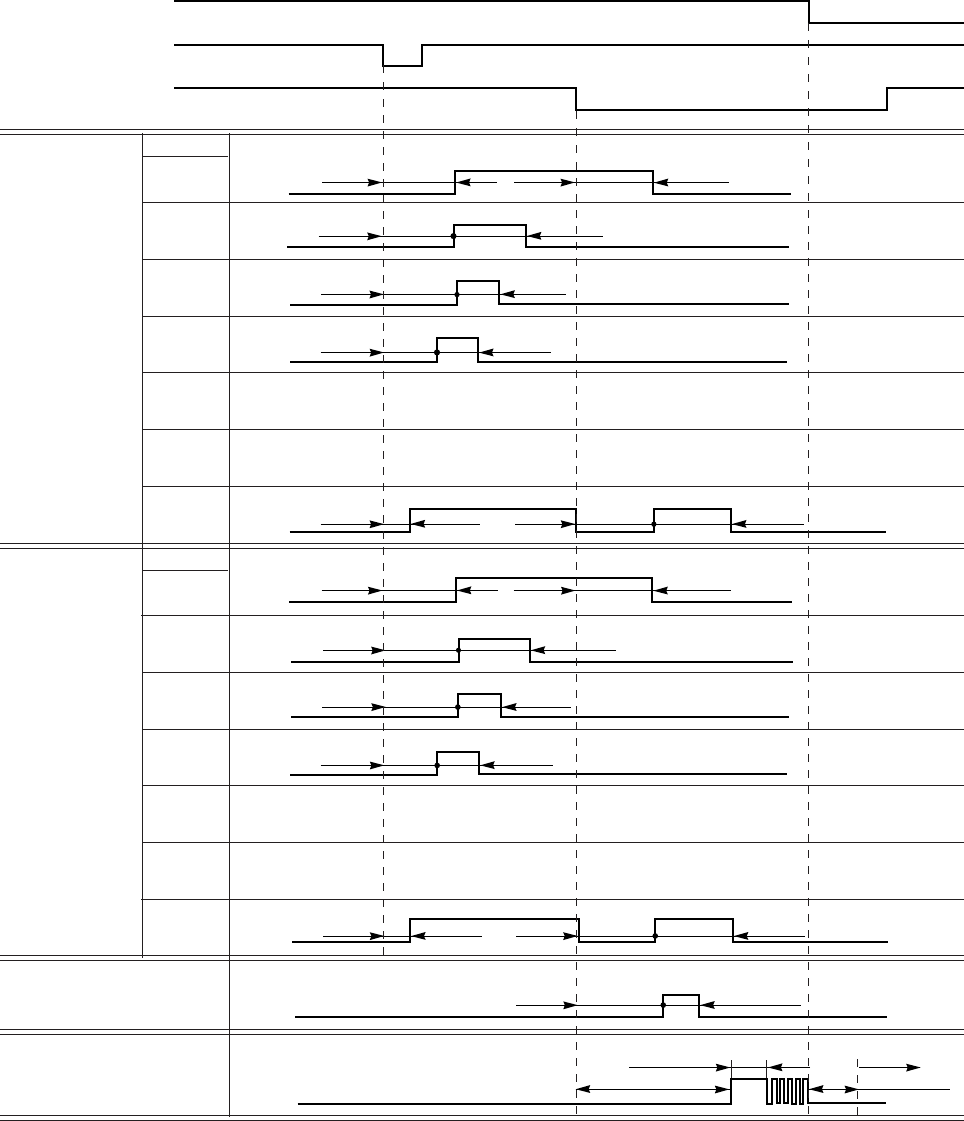
− 51 −
12. SETTING IN THE THREAD TRIMMING MODE TR
1) Thread trimming timing when thread trimming mode TR setting is PRG
(1) Output timing of thread trimming output
F1(ms) FD(ms)
Notes : *1. The wiper output [W] operation will be special according to the G mode WMD setting.
*2. The presser foot lifter [FU] chopping duty can be set with FUD in the P and C mode.
Run signal S1
Needle DOWN
position DN
Needle UP
position UP
ON
ON
ON
Thread trimming
T
LTM setting
T1
T2
T3
T4
TK
TS
T7
Tread release L
LLM setting
L1
L2
L3
L4
LK
LS
L7
TS (Deg) T2(ms)
TS(Deg) TE(Deg)
TS(Deg) T2(ms)
T1(ms) T2(ms)
TS(Deg) T1(ms) T2(ms)
LS(Deg) L2(ms)
LS(Deg) LE(Deg)
LS(Deg) L2(ms)
L1(ms) L2(ms)
LS(Deg) L1(ms) L2(ms)
Wiper W
Presser foot lifter FU
*1
*2
W1(ms) W2(x 10 ms)
F(x10 ms) Motor ON
Cannot be used.
Cannot be used.
Cannot be used.
Cannot be used.
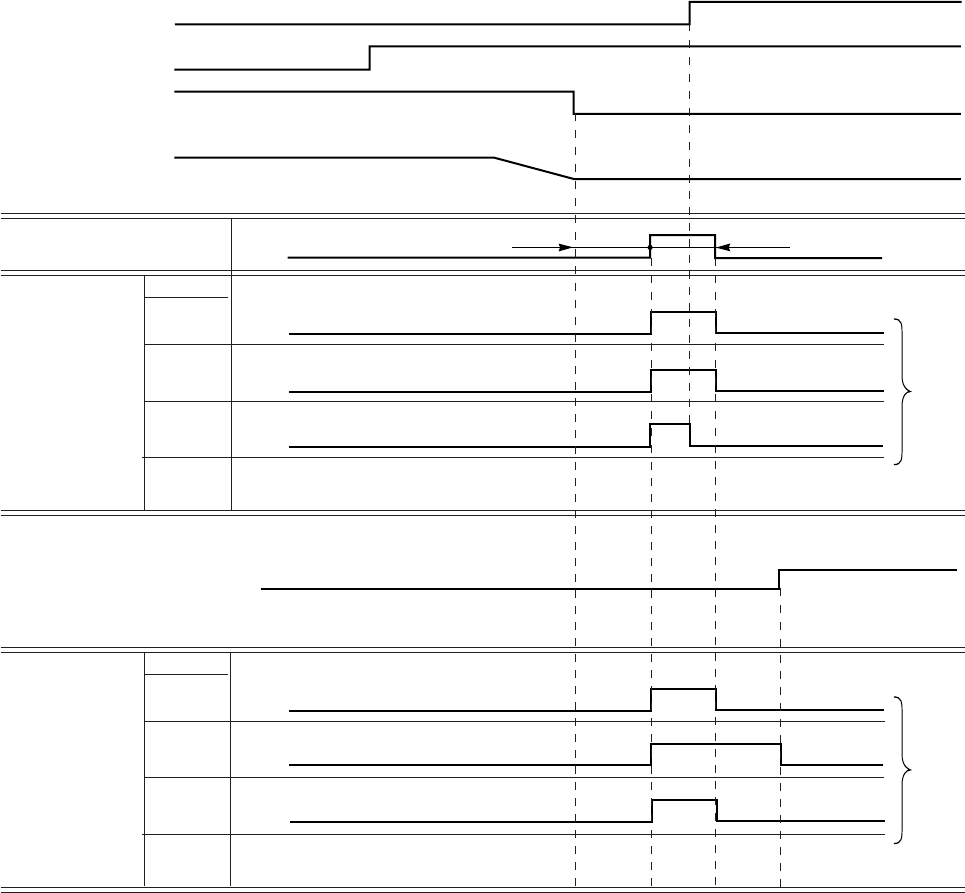
− 52 −
(2) Wiper output timing
Wiper output OFF timing with (S2) signal WMD (in program mode G) [1]
* Wiper output OFF timing is changed by S2 signal OFF timing like above chart [1] and [2].
Wiper output W
WMD setting
W
OR
AN
Wiper output W
WMD setting
W
OR
AN
Thread trimming
signal S2 ON
Needle DOWN
position DN
Needle UP
position UP
Sewing machine
Wiper output setting time
Thread trimming signal S2
ON
ON
ON
ON
ON
ON
ON
ON
ON
W1 [ms] W2(x10)
[1]
[2]
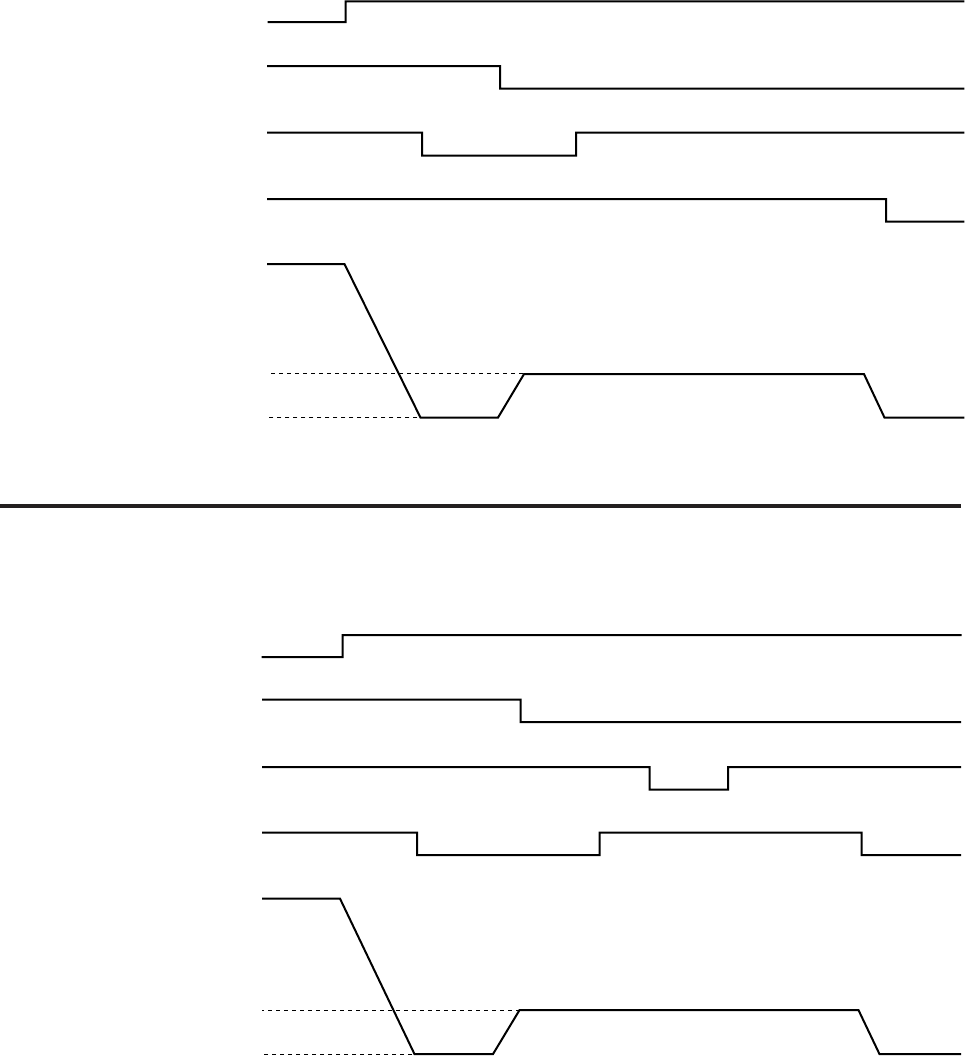
− 53 −
2) Sewing machine motion pattern
Thread trimming mode [TR] in program mode P or G ……Function setting [TR[PRG]]
(1) Function setting [TRM [LK]] in program mode G
[1] Full-heeling after 2 position stop
[2]Full-heeling after 1 position stop
ON
ON
ON
ON
ON
ON
ON
ON ON
Run signal S1
Thread trimming signal S2
Needle DOWN position DN
Needle UP position UP
Speed H
Sewing machine
Speed T
0
Run signal S1
Thread trimming signal S2
Needle DOWN position DN
Needle UP position UP
Speed H
Sewing machine
Speed T
0
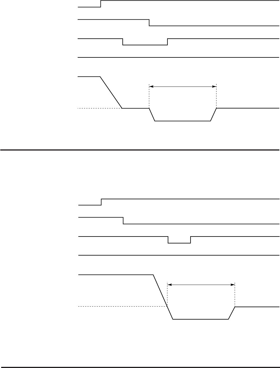
− 54 −
(2) Function setting [TRM [RK]] in program mode G (Function setting [S2R [OF] ])
[1] Full-heeling after 2 position stop (Tacking is invalid.)
Notes : 1. The same operation as G mode TRM=LK will occur when set to 1 position.
2. The reverse angle can be set with R8 in the P mode. (*1)
[2] Full-heeling (2 position) (Tacking is invalid)
ON
ON
ON
ON
ON
ON
Run signal S1
Thread trimming signal S2
Needle DOWN position DN
Needle UP position UP
Sewing machine
Forward
Reverse
*1 R8(Deg)
Run signal S1
Thread trimming signal S2
Needle DOWN position DN
Needle UP position UP
Sewing machine
Forward
Reverse
*1 R8(Deg)
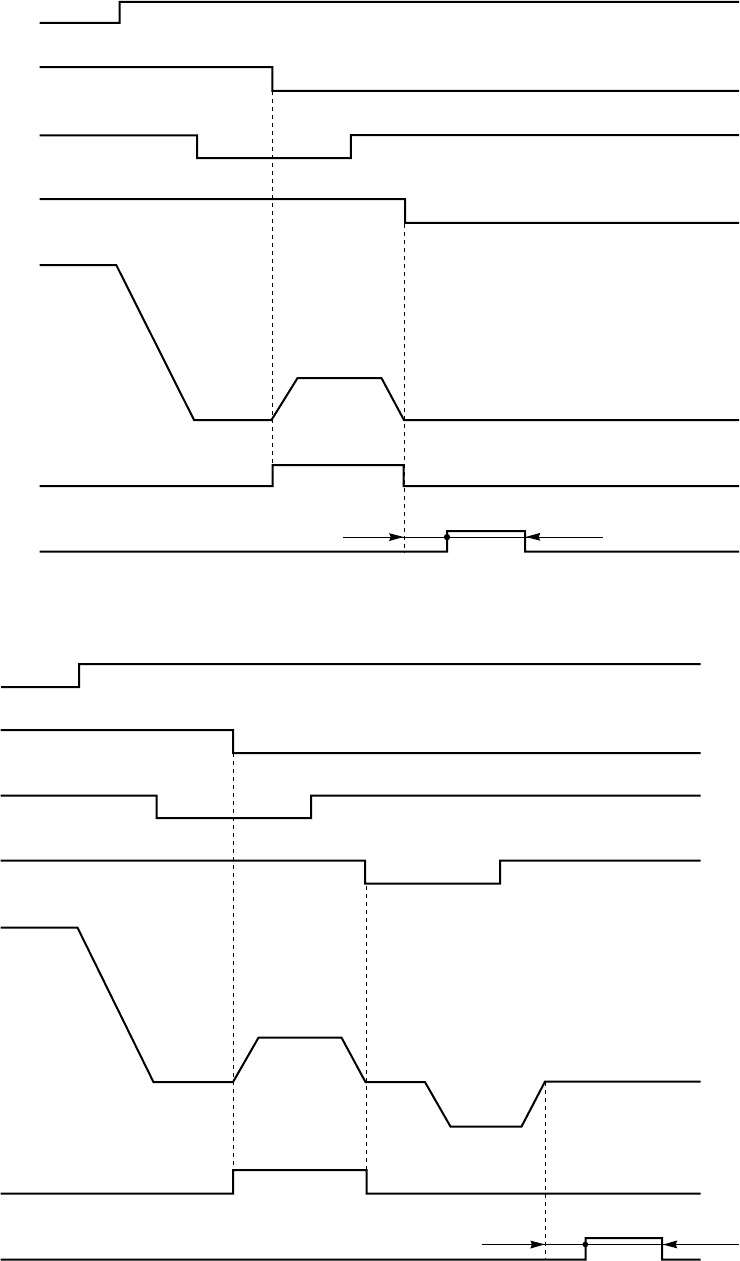
− 55 −
13. OUTPUT TF, TB TIMINGS
1) Output normal timing
Note) 1. The TF output start time can be set with R1 in the G mode.
The TF output time can be set with R2 in the G mode.
2. The above-mentioned timing is function setting [TRM[LK]] in program mode G.
2) Function setting [RU [ON] ] in program mode P
ON
ON
ON
ON
ON
ON
ON
ON
ON
ON
Run signal S1
Thread trimming signal S2
Needle DOWN position DN
Needle UP position UP
Sewing machine
Output TB
Output TF
R1=40 ms R2=66 ms
Run signal S1
Thread trimming signal S2
Needle DOWN position DN
Needle UP position UP
Sewing machine
Output TB
Output TF
R1=40 ms R2=66 ms
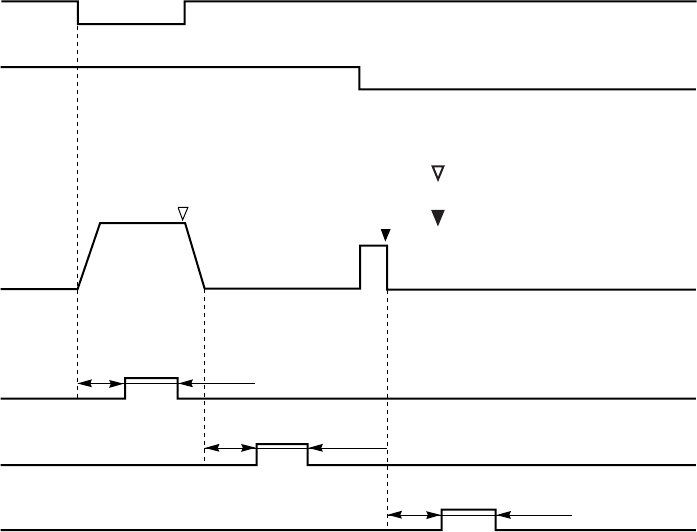
− 56 −
14. OUTPUT KS1,KS2,KS3 TIMINGS
Note) The KS1 to KS3 output start time and output time can be set with K11 to K32 in the S mode.
(Caution) This timing chart (sequence) is only available when [SQS] is set to [NO].
When [SQS] is not set to [NO], please refer to “[15] Simple sequence”.
ON
ON
Run signal S1
Thread trimming signal S2
Sewing machine
Output KS1
Output KS2
Output KS3
K11=70
ms K12=70 ms
K22=70
ms
K21=70
ms
K31=70
ms K32=70 ms
Needle DOWN position stop
Needle UP position stop
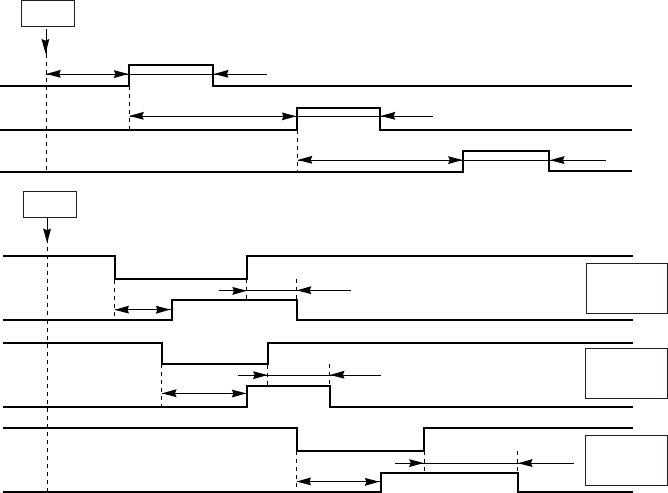
− 57 −
15. SIMPLE SEQUENCE
The function outputs [KS1], [KS2] and [KS3] can be set as simple sequence outputs.
To set the simple sequence output, the starting conditions [IN] [T] [R] [S] [TR] [SB] [GO] are set in the
simple sequence starting condition
Setting function [SQS] of the [S] mode. With this, function outputs [KS1],[KS2] and [KS3] will be simple
sequence outputs. (The default setting is the [NO] setting.)
1. Simple sequence starting conditions
The function outputs [KS1],[KS2] and [KS3] can be set as simple sequence outputs.
[NO] : The simple sequence is not started. (The default setting is the [NO] setting.)
(Refer to “[18] Output KS1,KS2,KS3 timings”.)
[IN] : When input signal I4 (IN4) is turned ON.
[T] : When thread trimming is completed.
[R] : When operation is starting.
[S] : When motor is stopped. (This also includes when single-stitch operation is stopped.)
[TR] : When starting stitching after thread trimming.
[SB] : When start tacking is completed. (This will not start if the start tacking setting is “NO”.)
[GO] : Always start.
2. Simple sequence output timing chart
Explanation of setting function
(a) Sequence output [KS1][KS2][KS3] output start time/No. of stitch setting changeover [NS1][NS2][NS3]
[OF] setting : Time setting ([K11][K21][K31] : 10 msec unit)
[ON] setting : No. of stitch setting ([K11][K21][K31])
(b) Sequence output [KS1][KS2][KS3] output start time/No. of stitch setting changeover [NS1][NS2][NS3]
[OF] setting : Time setting ([K12][K22][K32] : 10 msec unit)
[ON] setting : No. of stitch setting ([K12][K22][K32])
(c) Sequence output [KS1][KS2][KS3] output reference setting [S1S][S2S][S3S]
[OF] setting : The output start reference will be as shown in the timing chart[2-1]above.
[ON] setting :The output start reference will be the input signal ON reference as shown in the timing
chart[2-2] above
(d) Sequence output [KS1][KS2][KS3] output reference setting [S1E][S2E][S3E]
[OF] setting : The output end reference will be as shown in the timing chart [2-1] above.
[ON] setting : The output end reference will be the input signal ON reference as shown in the timing
chart [2-2] above
Note) 1. When using the simple sequence make each simple sequence related setting shown
above, and assign the function output [KS1][KS2][KS3] to the output setting of the output
pin being used by setting the C mode output function.
2. If the starting conditions are not set in the simple sequence setting starting condition
setting [SQS] above (when [NO] is set), the function output [KS1][KS2][KS3] will have the
output timing shown on the next page.
S3S[ON]
S3E[ON]
2-1. Start (The operation will start when the starting conditions are satisfied.)
Start (The operation will start when the starting conditions are satisfied.)
2-2.
Output KS1
Output KS2
Output KS3
Input signal I2
Output KS1
Input signal I7
Output KS2
Input signal I6
Output KS3
ON
ON
ON
ON
ON
ON
ON
ON
ON
K11 K12
K21 K22
K31 K32
K11 K12 S1S[ON]
S1E[ON]
K21 K22 S2S[ON]
S2E[ON]
K31 K32
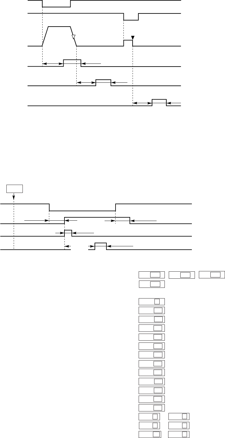
− 58 −
3. When starting condition setting [SQS] is [NO] (default setting)
Output timing of output [KS1] [KS2] [KS3]
[KS1] : Output for [K12] after the [K11] time after the motor starts rotating.
[KS2] : Output for [K22] after the [K21] time after the motor stops.
[KS3] : Output for [K32] after the [K31] after thread trimming (or needle lift) stop by pedal heeling.
Note) 1. The output [KS1] [KS2] [KS3] output start time and output time can be adjusted with
[K11] [K32] in the [S] mode.
4. Example of simple sequence setting
When the following timing output is to be output to the option B connector’s No.3 pin,No.12 pin and No.15 pin.
[OUT1][OUT2][OUT3]
Setting
1. Function setting of [C] mode
(1) Output function setting O1 KS1 O2 KS2 O3 KS3
(2) Input function setting I2 IO1
2. Function setting of [S] mode
(1) Simple sequence starting condition setting SQS T
(2) KS1 output’s output start time/No. of stitch setting changeover NS1 ON
(3) KS1 output’s output time/No. of stitch setting changeover NE1 ON
(4) KS1 output’s output start reference setting S1S ON
(5) KS1 output’s output end reference setting S1E ON
(6) KS2 output’s output start time/No. of stitch setting changeover NS2 OF
(7) KS2 output’s output time/No. of stitch setting changeover NE2 OF
(8) KS2 output’s output start reference setting S2S OF
(9) KS2 output’s output end reference setting S2E OF
(10) KS3 output’s output start time/No. of stitch setting changeover NS3 ON
(11) KS3 output’s output time/No. of stitch setting changeover NE3 OF
(12) KS3 output’s output start reference setting S3S OF
(13) KS3 output’s output end reference setting S3E OF
(14) KS1 output’s output start No. of stitches * output No. of stitches setting K11 3K12 3
(15) KS2 output’s output start time * output time K21 0K22 6
(16) KS3 output’s output start No. of stitches * output time K31 12 K32 8
Run input S1
Trim input S2
Sewing machine
Output KS1
Output KS2
Output KS3
ON
ON
ON
ON
ON
K12=70
ms
K11=70
ms
K21=70
ms K22=70
ms
K31=70
ms
K32=70
ms
ON
ON
ON
ON
Input signal I2
Output KS1
Output KS2
Output LS3
K11=3 stitch K12=5 stitch
K21=0 ms K22=60 ms
K32=80 ms
K31=12
stitch
Start (The operation will start when the starting conditions are satisfied.)

− 59 −
16. COMMUNICATION FUNCTION
Specification
Connector Mini-DIN connector 6-pin
Signal level Doing based of RS-232C
Baud rate 9600 bps
Operation mode Asyncrouns
Start bit 1 bit
Data length 8 bit
Parity none
Stop bit 1 bit
Record format Original
Function The reading with various multiple time and various counter-value
1. About the communication
When communication among the equipment, it becomes the method which returns the reply by receiving a
direction by this product.
Equipment (being computers such as the personal computer in this communication function) on the side
which issues this direction is called a parent machine and equipment
(being SC-380 form control board in this communication function)
The child machine sends an answer only to the inquiry from the parent machine.
For example, when wanting to take out data continuously, it makes require repeat data on the side of the
parent machine. The form of the data, the electric characteristic, the communication protocol and so on
must be each other adjusted, to communicate difference machine.
1-1. The electric characteristic
It defines the definition of the voltage level and High/Low of the signal, the airlines of the communication
and so on. This communication function is based on RS-232C which are an international standard, the
parent machine which has to do RS-232C or of RS-232C display and based a can be connected with.
1-2. The communication procedure (protocol)
The protocol to be using for this communication function is the original method of the SC-380. Because this
protocol can not be changed, make a program to agree with this protocol on the side of the parent machine.
2. Wiring
2-1. The pin arrangement by the connector
Connector H
Pin number Signal name I/O The use
1 RXD I Receive data
2 – No use
3 TXD O Send data
4 COM Control common
5 +12 V Power supply
6 – No use
Peripheral plate FG Grounding for the shield
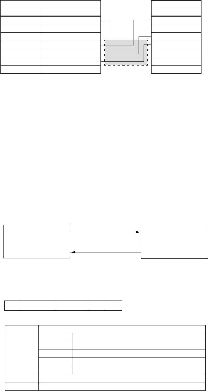
− 60 −
2-2. The manufacturing of the data
It makes the wiring figure of the following figure reference and manufacture machine.
a cable and connect a child machine and a parent
Note : Please be careful because the pin number to the signal and so on depend on the computer.
2-3. The attention item in case of wiring
(1) Please use a numerous wick cable with the shield and the shield connect with FG surely.
(2)The wiring distance depend on the environment around but use at the distance which is as short as
possible.
3. The basic procedure
3-1. Commands
Transmitting a user command to the child machine from the parent machine.
It is answered that it does ACK to these all transmissions of it. (Note 1)
Note) 1. As for the partial command, the data which it was answered that it does and input condition
itself become ACK. And all data transfer is used by ASCII code.
3-2. The sending and receiving of the various command.
3-2-1. User command (Parent machine → Child machine)
It manufactures optional data and it answers when receiving data.
(1) 9-byte fixation
SC-380
Parent side
Signal name Contents
FG Ground
——
——
TXD Send data
RXD Receive data
COM Common for the signal
——
Child side
Signal name
RXD
—
TXD
COM
+12 V
—
FG
Parent machine Child machine
(1) User command
(2) User command data
(3) ACK
Personal computer and so on
? Command Check sum CR LF
14 211
? Start code
Command
“SYSV” Answer the version of the system.
“DATV” Answer the version of the EEPROM data.
“TYPE” Answer the type.
“ **** ” Command (Refer to the command list)
Check sum Add ASCII code of user command and invert all bit (refer note 1)
CR + LF End code
Answer of the data (Child machine → Parent machine)
Command

− 61 −
(2) 13-byte fixation
(3) 13-byte fixation
Note) 1. For example to make check sum of (13-byte fixation command “type”) *refer 4-1. The
user command 1.
1) ”type” ASCII code is 54,59,50.45.
2) Add ASCII code. (54+59+50+45=142)
3) It uses 2 digits below for the computation. (use 42 of 142)
It uses 42 out of 142.
4) Invert all bit of 42. (Again, it hangs reduction 1 and it adds up 1.)
The result which inverted all bit of 42 is BD.
5) The check sum is BD The check sum is BD.
4. The communication command list
4-1. The user command 1 (Permitted to data clear)
# Start code
Command Received command (echo)
Data Data which corresponded to the command
Check sum Add ASCII code of user command and Data and invert all bit (refer note)
CR + LF End code
At the time of the reception error, following ACK is returned.
Answer of ACK (Child machine → Parent machine)
Form of the answer data
Numerical value
Numerical value
Numerical value
Numerical value
Numerical value
Numerical value
Numerical value
Numerical value
Numerical value
Numerical value
Numerical value
Numerical value
Numerical value
Numerical value
Numerical value
Numerical value
Numerical value
Numerical value
Numerical value
# Command Data Check sum CR LF
14 4 2 11
# Start code
E000 Normal end
E001 Recode type error
E002 Check sum error
No used Unsettled
Check sum Add ASCII code of user command and invert all bit (refer note 1)
CR + LF End code
E***
# E** No used Check sum CR LF
14 4 2 11
Command
PPWH
PPWL
PMTH
PMTL
PSTH
PSTL
PFUH
PFUL
PTRM
TPWH
TPWL
TMTH
TMTL
TSTH
TSTL
FULH
FULL
TTRM
TCYC
Contents
Integrating power supply time1 (upper 1 word)
Integrating power supply time2 (lower 1 word)
Integrating motor ON time1 (upper 1 word)
Integrating motor ON time2 (lower 1 word)
Integrating needle stitches1 (upper 1 word)
Integrating needle stitches2 (lower 1 word)
Full speed time1 (upper 1 word)
Full speed time2 (lower 1 word)
Thread trimming the number of times
Integrating power supply time 1 (upper 1 word)
Integrating power supply time 2 (lower 1 word)
Integrating motor ON time 1 (upper 1 word)
Integrating motor ON time 2 (lower 1 word)
Integrating needle stitches 1 (upper 1 word)
Integrating needle stitches 2 (lower 1 word)
Full speed time 1 (upper 1 word)
FULL Full speed time 2 (lower 1 word)
Thread trimming the number of times
Number of the integrating cycles (UP CONTER)

− 62 −
Form of the answer data
Numerical value
(Only subordinate position 15 bit is used).
9 : Solenoid overcurrent
8 : Detector error
6 : Noise error
5 : EEPROM error
4 : Motor connector omission
3 : Encoder error. Motor, sewing machine lock error
2 : Over voltage
1 : Transistor module error
FFFF (YES)
0000 (NO)
Numerical value
Numerical value
Numerical value
Numerical value
Numerical value
FFFF (YES)
0000 (NO)
FFFF (YES)
0000 (NO)
Numerical value
FFFF (Presser foot OFF)
0000 (Presser foot ON)
FFFF (YES)
0000 (NO)
FFFF (Connected)
0000 (none)
FFFF (YES)
0000 (NO)
Numerical value
Only subordinate position 4 bit is used.
***0 The number of trimming times become “1”
***1 The number of sewing stitch become “N”
(Function setting [CUN.] in program mode B)
***2 The number of trimming times become “N”
(Function setting [PRN.] in program mode B)
***3 When input function “IO1” become ON.
***4 When output function “O1” become ON.
Note : *** is irregular.
Numerical value
Numerical value
(Only subordinate position 12 bit is used.)
Command
EROR
ERR1
ERR2
ERR3
ERR4
ERNW
PAT.
USET
UCNT
DSET
DCNT
UPCT
DPCT
SPDD
OSAE
THRE
BOX_
MOVE
SRV_
UTYP
DTYP
WT_
VOLT
TYPE
SYSV
DATV
Contents
Error code
Error code Once ahead
Error code Twice ahead
Error code Three times ahead
Error code Four times ahead
In the error
Pattern number
UP counter setting value
UP counter value
DOWN counter setting value
DOWN counter value
UP counter ON/OFF
DOWN counter ON/OFF
Setting speed
Condition of the presser foot lift
Thread break detector ON/OFF
Control panel (Connected/none)
In sewing
The principal axis number of rotations
Present count UP way
Present count DOWN way
Watt
Voltage
Swing machine type
Version of the system
Version of the data
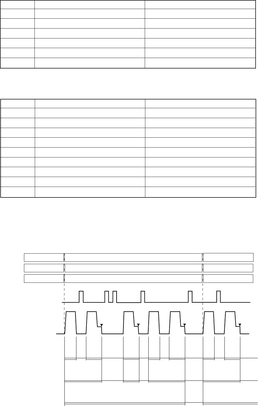
− 63 −
4-2. User data command 2 (Data clear command)
4-3. User command 3
(Caution) 3 BIT of the place is the order.
13 BIT of the subordinate position is time (unit of 0.1 s) or frequency.
(Reference chart 1)
Command Contents Form of the answer data
MTON Motor ON time Numerical value
MTOF Motor OFF time Numerical value
ATON Idle time after the thread trimming Numerical value
ATOF The integrating time to the thread trimming Numerical value
CYON Idle time after the one cycle Numerical value
CYOF One cycle time Numerical value
CYOS One-cycle foot lifting frequency (multiplication) Numerical value
CYTR
One-cycle thread trimming frequency (multiplication)
Numerical value
CYMT One-cycle motor stop frequency (multiplication) Numerical value
ATON(1) ATOF(1) ATON(3) ATON(4) ATOF(4)
Command Contents Form of the answer data
PPCL Integrating power supply time clear Data which can be cleared becomes 0.
PMCL Integrating motor ON time clear Data which can be cleared becomes 0.
PSCL Integrating needle stitches clear Data which can be cleared becomes 0.
PFCL Full speed time clear Data which can be cleared becomes 0.
PTCL Integrating needle stitches clear Data which can be cleared becomes 0.
PCCL Number of the integrating cycles clear Data which can be cleared becomes 0.
CYOS CYOS (1) =0 CYOS (2) =5
CYTR CYTR (1) =0 CYTR (2) =3
CYMT CYMT (1) =0 CYMT (2) =4
Foot lifter
Sewing machine
(▼ : Thread trimming)
on on on on on on
MTON(1)
MTOF(1)
MTON(2)
MTOF(2)
MTON(3)
MTOF(3)
MTON(4)
MTOF(4)
MTON(5)
MTOF(5)
MTON(6)
MTOF(6)
MTON(7)
MTOF(7)
CYON(1) CYON(2)
ATOF(2)
ATON
(2) ATON
(3)
CYOF
(1)
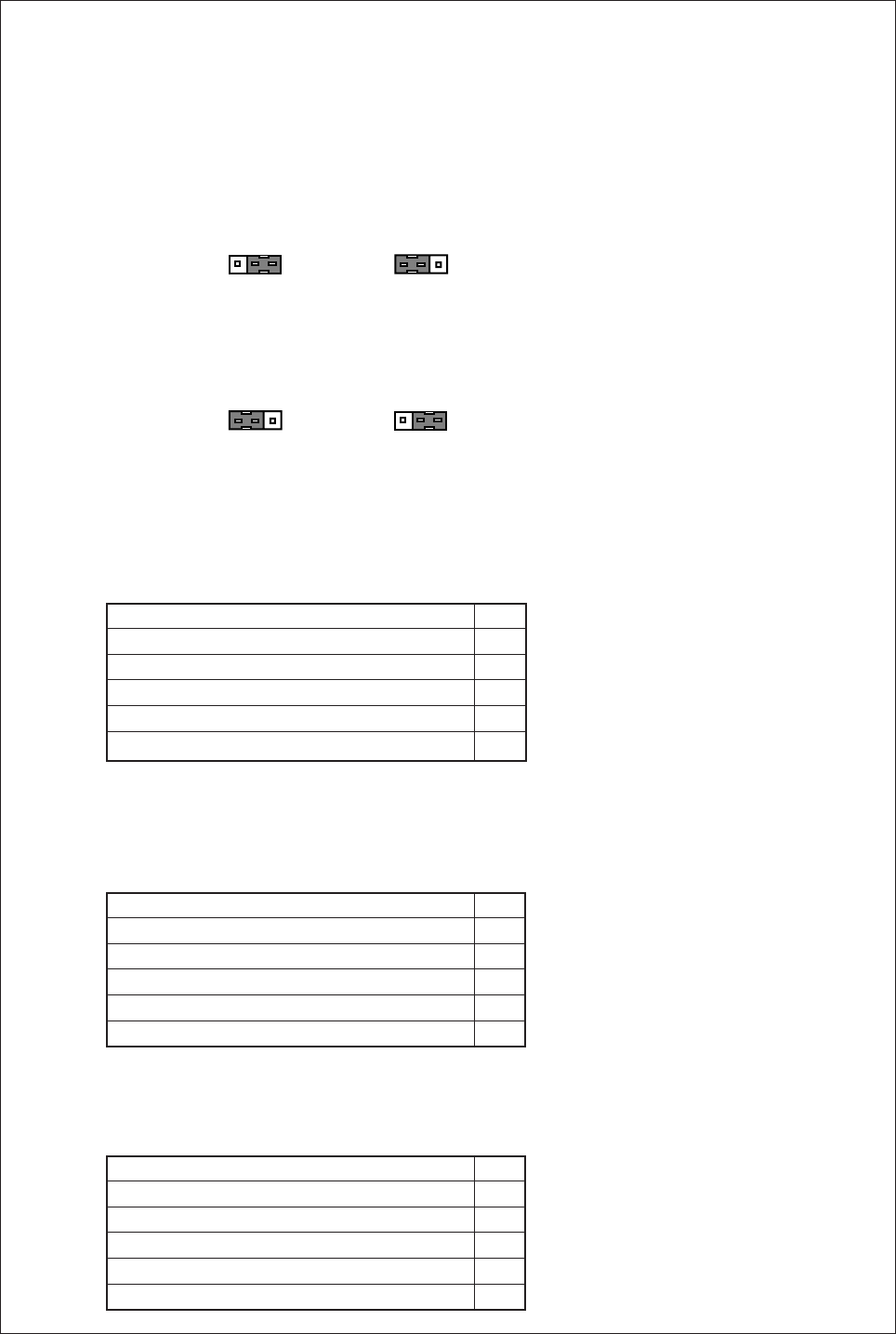
− 64 −
17. HOW TO CHANGE VOLTAGE OF PANEL CONNECTOR AND SOLENOID
RETURN SPEED
1. To change Solenoid voltage 24 V/30 V. (Refer to page 13.)
2. How to change the output voltage DC5 V/12 V
(1) Remove the cover.
(2) The DC5 V/12 V can be changed with the J2, J6,J7,J10 and J11 connector on the printed circuit
board on the cover side as shown next page.
(3) This is set to 12 V when shipped from the factory. To change from 5 V to 12 V, pull out the connector
and reinsert it into the 5 V side.
This is set to 5 V when shipped from the factory. To change from 12 V to 5 V, pull out the connector
and reinsert it into the 12 V side.
(4) The power supply (+12 V) voltage will change form 12 V to 5 V by changing the J10 connector from
12 V to 5 V.
Position detector
(5) The power supply (+12 V) voltage will change form 12 V to 5 V by changing the J11 connector from
12 V to 5 V. (When wanting to make change gears of the sewing machine possibly at variable speed
command of 5 V, set the setting value of pedal curve function setting <PDC> by the A mode.)
Lever (white connector)
(6) The power supply (+12 V) voltage will change form 12 V to 5 V by changing the J7 connector from 12
V to 5 V.
Option A
e
J2, J7, J10, J11
+5 V
+12 V
J2, J7, J10, J11
+5 V
+12 V
+5 V
+12 V
+5 V
+12 V
e
J6 J6
0 V 1
—2
Ground 3
UP 4
DOWN 5
+12 V/ (+5 V) 6
0 V 1
S1 : Run (Variable speed) 2
S2 : Tread trimming 3
S3 : Presser foot lifte 4
VC : Variable speed command 5
+12 V 6
0 V 1
PSU : Up position stop input 2
+12 V 3
PSD : Down position stop input 4
CKU : Up position output 5
S0 : Low speed input 6
…12 V = = > 5 V
…12 V = = > 5 V
…12 V = = > 5 V
…12 V = = > 5 V
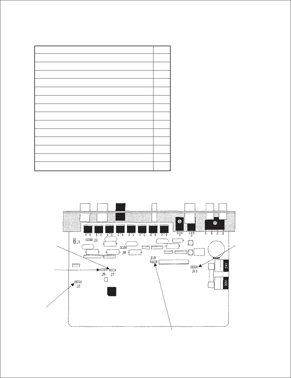
− 65 −
(7) The output of pin number 2, 5,13,14 will change from 12 V to 5 V by changing the J2 connector from
12 V to 5 V, also the power supply (+5 V : Pin number 7) voltage will change form 5 V to 12 V by
changing the J6 connector from 5 V to 12 V.
Option B
0 V 1
No setting 2
OT1 : Virtual output 3
VC2 : Variable speed command 4
No setting 5
IO1 : Virtual input 6
+5 V 7
+30 V 8
U : Needle lift signal 9
0 V 10
+30 V 11
NCL : Needle cooler output 12
No setting 13
No setting 14
TF : “TF” output 15
…12 V = = > 5 V
…12 V = = > 5 V
…5 V = = > 12 V
…12 V = = > 5 V
…12 V = = > 5 V
Option A
DC5 V/12 V
changeover switch
Option B
DC5 V/12 V
changeover switch
(Pin No.7)
Option B
DC5 V/12 V
changeover switch
(Pin No. 2, 5, 13, 14
Pull up Voltage) Position detector
DC5 V/12 V
changeover switch
Lever connector
DC5 V/12 V
changeover switch
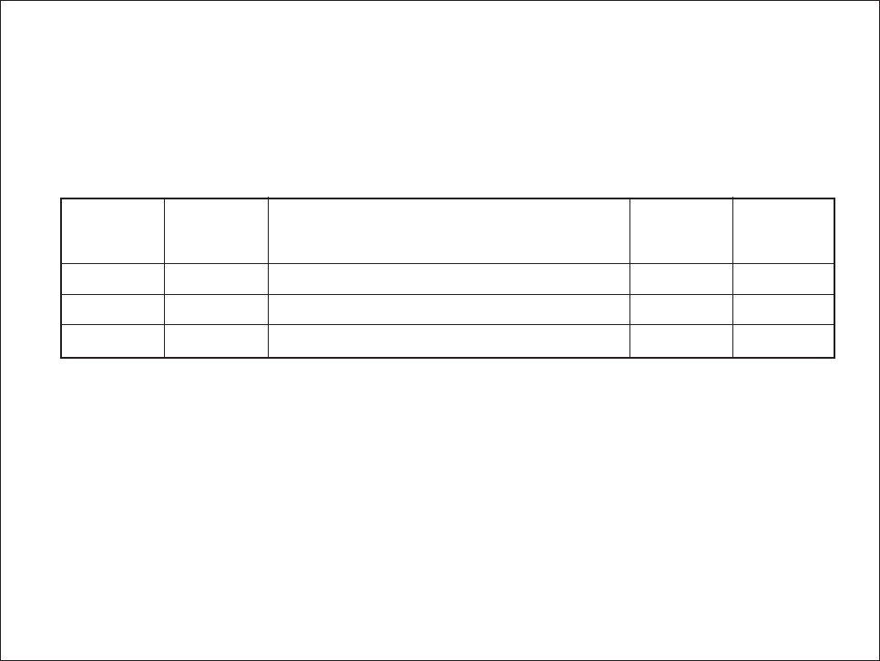
− 66 −
3. How to set the switch for increasing the solenoid return speed.
(1) Remove the cover.
(2) The solenoid return speed can be increased with the setting of the J1, J5, J8 connector on the
printed circuit board on the cover side as shown on the last page.
(3) Connector factory settings and solenoid return
(4) Set the connector setting from SLOW to FAST increase the solenoid return speed.
(Caution) The solenoid return cannot be increased if solenoid output chopping duty OAC, ODC,
and O3C is return ON in the program mode [C].
The resistance on the printed circuit board will be burnt out if the solenoid return
speed is increased.
If “UNION SPECIAL” [UN1], [UN2] and [UN3] are set in program mode [2], always use
J1 and J8 set at SLOW (solenoid return is normal), J5 set at FAST (solenoid return is
fast).
J1 FAST Sewing machine connector I1-I2 pin output. Normal OC
J5 SLOW Sewing machine connector 3-4 pin output. Normal OA
J8 SLOW Sewing machine connector 7-8 pin output. Normal OD
Output
Solenoid
return
Output during simple setting
Connector
factory
setting
Connector
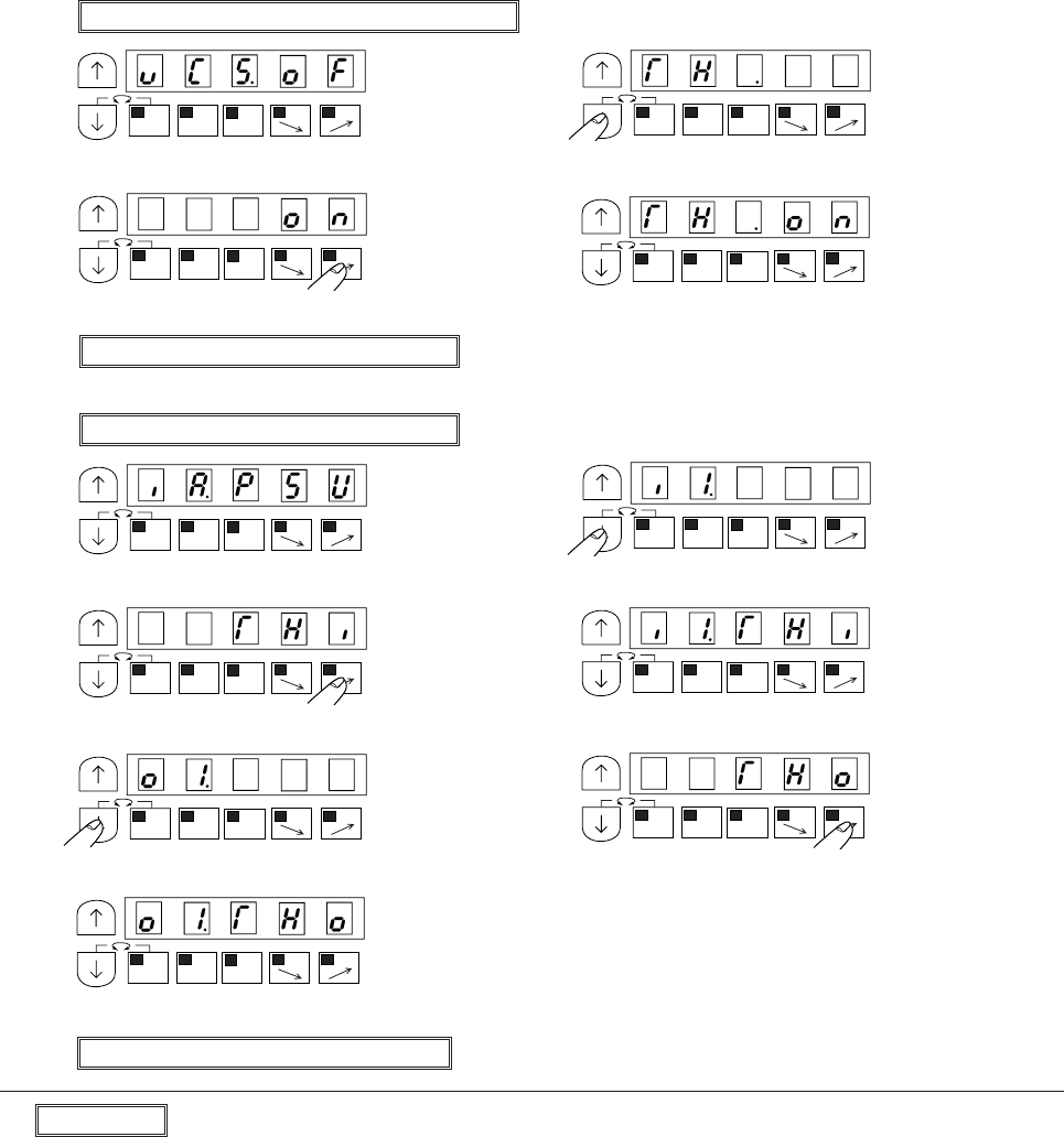
− 67 −
18. HOW TO SET THREAD BREAK DETECTOR
1. Setting Thread break detector function
(1) Set to program mode “Q” ([ ↓] + [A] + [C])
(2) (3)
* Program mode “Q” will be entered. * Set to “TH”
(4) (5)
* Set to “ON” * Complete the “TH” function setting.
(6) Return to normal mode ([ ↓] + [ ↑])
(1) Set to program mode “C” ([ ↓] + [C])
(2) (3)
* Program mode “C” will be entered. * Set to “I1”
(4) (5)
* Set to “THI” * Complete the “I1” function setting.
(6) (7)
* Set to “O1” * Set to “THO”
(8)
* Complete the “O1” function setting.
(9) Return to normal mode ([ ↓] + [ ↑])
Description
Selection the function on program mode “Q”.
[TH.ON] To use upper thread break detector function, set to “ON”
[TH.OFF] Upper thread break detector function is invalid.
MA
1-2
B
SL
CD
MA
1-2
B
SL
CD
MA
1-2
B
SL
CD
MA
1-2
B
SL
CD
MA
1-2
B
SL
CD
MA
1-2
B
SL
CD
MA
1-2
B
SL
CD
MA
1-2
B
SL
CD
MA
1-2
B
SL
CDMA
1-2
B
SL
CD
MA
1-2
B
SL
CD

− 68 −
Selection the function on program mode “C”.
2. Timing chart of thread break input and output.
Term (1) : Sewing machine speed is under “B” speed, so it neglect thread break function.
Term (2) : After sewing machine speed become over “B” speed,still under “THS” stitch amount, so it neglect
thread break function.
Term (3) : Thread break function is valid.
Term (4) : The judgment stitch amount “THF” of thread break, after this stitch amount, thread break function
move to “TST” function.
Setting the action, after thread was broken.
“THO” output function become on and continue to sew.
“THO” output function become on and trimming thread.
“THO” output function become on and sewing machine will be stooped.
* When the sewing machine run,”THO” output will be clear.
To set the speed neglect thread break function.
When sewing machine rotation speed become under this speed, it neglect thread break function.
[B.] Setting the neglecting stitch amount from first stitch.
Setting the judgment stitch amount of thread break.
[TST]
[NO.]
[TR.]
[ST.]
[B.]
[THS.]
[THF]
[I1.THI] No.6 pin of option connector B will be set to thread break input function.
[O1.THO] No.3 pin of option connector B will be set to thread break output function.
ON
ON
ON
run signal S1
Sewing machine Speed “B”
Thread break input [THI]
Thread break output[THO]
Fig 1 Timing chart
(1) (2) (3)
(4)
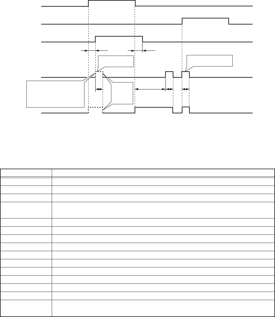
− 69 −
19. CUTTER OUTPUT
1) Cutter
Note) Use of the I*1 input is prohibited when using the blower output.
F mode setting
Note) 1. Always set O2M to ON even when not using the air output.
2. Customize the option connectors I1, I2 and O1 to O3 to the required functions using the
program mode beforehand.
If operation is started after the
sensor input IO2 has turned ON
while the sewing machine is
stopped, the output will be
canceled when CTS is ON.
ON
ON
ON
OFF
Foot switch (sensor)
IO2
Manual cutter input
I*3
Air output
OT2
Cutter output
OT3
Blower output
OT1
CTY=ON
O2M=ON
O3M=ON
OIB=ON
COA COB
SD SD SD
COC
Output canceled
when CSC is ON.
Output canceled when
CSC is ON.
Output
canceled
when CSC
is ON.
Specification
Set OT1 output to blower output.
Set OT2 output to air output.
Set OT3 output to cutter output.
Add mesh judgment control to IO2 input. (If output stays ON or OFF for longer than the mesh
judgment time set with ED, the IO2 input will not be fixed.)
Set I*3 input to manual cutter input.
Set OT3 cutter output to both OFF → ON and ON → OFF of IO2 photo switch.
When IO3 is ON, turn OT3 output ON/OFF per set No. of stitches.
No. of stitches A
No. of stitches B
No. of stitches C
Cutter ON time
Mesh judgment time
The output of the automatic cutter output is prohibited while the sensor is ON.
The output of the automatic cutter output is prohibited while the sensor is OFF.
The output of the automatic cutter output is prohibited while the sensor input is ON while the
sewing machine is stopped.
Function name
O1B
O2M
O3M
I2M
CTY
CTM
CTR
COA
COB
COC
SD
ED
CSC
CEC
CTC
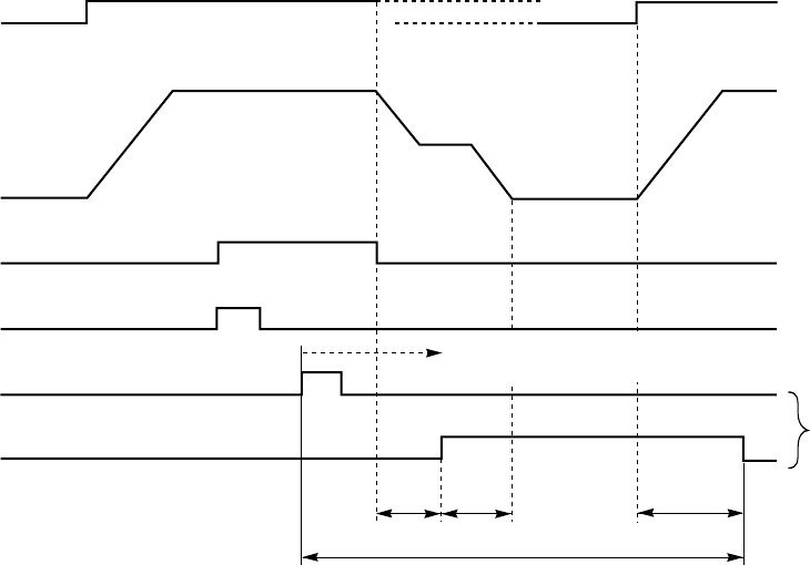
− 70 −
2) BT specifications (*1) operation chart and required settings
*1 : When CTL is set to ON, the BT specification operation will be applied after the I*1 input turns ON.
(If the BT output is turned OFF after I*1 turns OFF, the BT specifications will be canceled.)
*2 : S1 is invalidated after the photo sensor detection.
Operation will restart after stopping and then turning S1 OFF and ON.
*3 : Medium speed preset stitching when photo sensor turns OFF after BT input.
*4 : Up position stop after thread trimming.
*5 : Not output when photo sensor is OFF after BT input.
Note) 1. Always set O2M to ON even when not using the air output.
2. Customize the option connectors I1, I2 and O1 to O3 to the required functions using the
program mode beforehand.
3. The No. of stitch settings PSU, PSD and FCT are common with the other settings.
Thus, when using as the BT specifications, the PSU/PSD input and the function that
automatically lowers the presser with a timer cannot be used.
ON
ON
ON
ON
ON
Run signal
S1
Motor run
Sensor
Blower output
OT1
BT input
I*1
BT output
OP1
*2
*3
*4
*5
Middle
speed M
Following this, BT
specifications operation
X
(PSU) Y
(PSD)
Z
(FCT)
BT specifications operation
O2M=ON
O1B=ON
CTL=ON
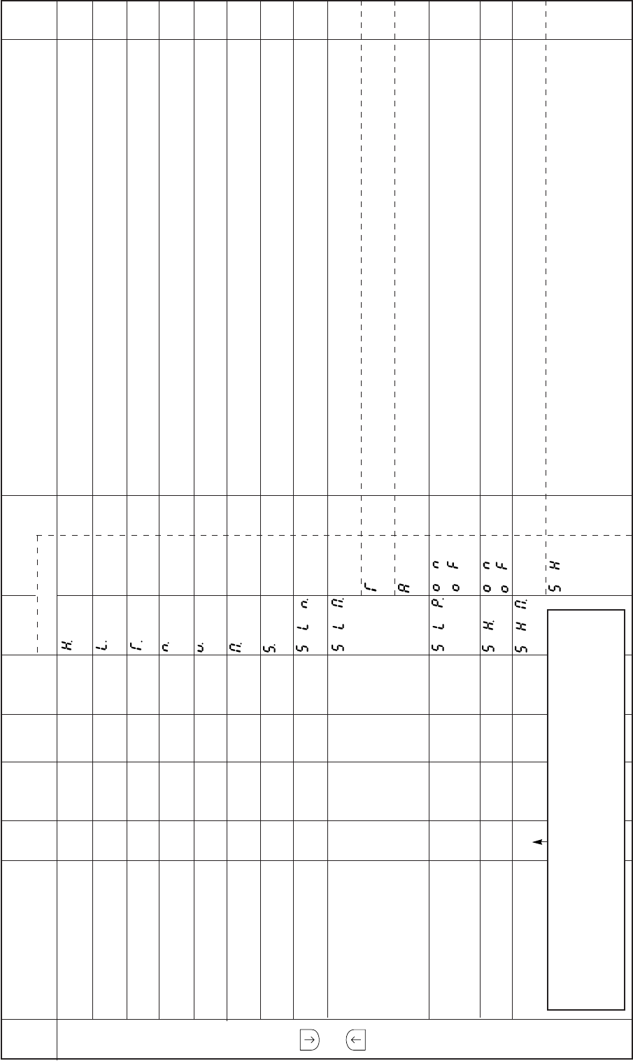
− 71 −
20. TABLE OF PROGRAM MODE FUNCTIONS
Mode
name Function name Oper
ability
Factory
setting Unit Setting
range Digital display
Function
name Setting
****
***
***
****
****
****
****
*
T
A
ON
OF
ON
OF
SH
Specification Ref.
page
P
mode
+
Maximum speed H.
Low speed L.
Thread trimming speed T.
Start tacking speed N.
End tacking speed V.
Medium speed M.
Slow start speed S.
No. of slow start stitches SLN.
Slow start operation mode SLM.
Slow start when power SLP.
is turned ON
One shot SH.
One shot operation mode SHM.
O
O
O
O
O
O
O
O
O
O
O
O
3500
170
170
1200
1200
2000
170
0
T
OF
OF
SH
r/min
r/min
r/min
r/min
r/min
r/min
r/min
Stitches
–
–
–
–
0 to 8999
0 to 499
0 to 499
0 to 2999
0 to 2999
0 to 8999
0 to 2999
1 to 5
–
–
–
–
The maximum speed can be set.
The low speed can be set.
The thread trimming speed to reach the needle UP position stop from the needle DOWN position
during full heeling of when thread trimmer signal (S2) is turned ON can be set.
The speed of start tacking can be set.
The speed of end tacking can be set.
The medium speed can be set.
The slow start speed can be set.
The No. of slow start stitches can be set.
This is valid when the [B.SL] key is ON in the normal mode.
The slow start operation mode is selected. This is valid when the [B.SL] key is ON in the normal
mode.
Slow start operation will begin when the power is turned ON or when the first toe down after thread
trimming, or the first external run signal ÅiS0, S1Åjis turned ON.
Slow start operation will begin when the pedal is toed down or when the external run signal (S0, S1)
is turned ON.
Slow start operation will begin when the pedal is toed down for the first time after turning the power
ON, or when the first external run signal (S0, S1) is turned ON even if the [B, SL] key is turned OFF
in the normal mode.
The one shot function can be selected. One shot operation (automatic operation) will begin when the
external run signals (S0, S1, S4) is turned ON.
The one shot SH operation mode is selected.
This is valid when one shot SH is [ON].
When one of the external run signals (S0, S1, S4) is turned ON the sewing machine will rotate at the
commanded speed while ON, and will continue operating even when the signal is turned OFF.
However, the speed will be that commanded with the speed setting key ([C,<= =], [D, = =>] key)
while OFF. (When the automatic operation function is turned ON in the normal mode.) Stops with
PSD, PSU, ES or SEN signal.
****
***
***
****
****
****
****
*
Caution
Operation validity
O mark : The sewing machine can be operated in the function setting state.
X mark : The sewing machine cannot be operated in the function setting state.
Operate the sewing after returning to the normal mode.
–
–
–
–
–
–
–
–
–
–
–
–
–
–
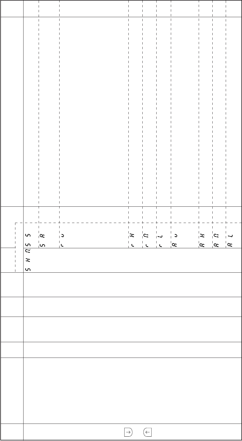
− 72 −
Mode
name Function name Oper
ability
Factory
setting Unit Setting
range Digital display
Function
name Setting Specification Ref.
page
When one of the external run signals (S0,S1,S4) is turned ON, the sewing machine will rotate at the
speed commanded with each signal even if the signal is turned OFF.
The same operation as when [SS] is set is included. When one of the external run signals (S0,S1,S4)
is turned (1) OFF=>ON=> (2) OFF=>ON, the sewing machine will stop (1) and will restart at (2)
.(Alternate operation).
If the automatic operation function is OFF and the one shot signal (SH) is turned ON, the sewing
machine will run at the low speed.
If the lever connector variable speed command [VC] is input in this state, the sewing machine speed
will be approximately in proportion with the voltage.
The sewing machine will continue to run at the speed proportional to the variable speed command
[VC] even if the one shot signal (SH) is turned OFF in the normal mode. If the automatic operation
function is ON and the one shot signal (SH) is turned on, the sewing machine will run at the speed set
with the speed setting key ([C, <= =], [D,= =>] key).
The sewing machine will continue to run at the set speed even if the on shot signal (SH) is turned
OFF.
The sewing machine will run at the maximum speed [H] when the one shot signal (SH) is turned ON.
The sewing machine will continue to run at that speed even if the signal is turned OFF.
The sewing machine will run at the medium speed[M] when the one shot signal (SH) is turned ON.
The sewing machine will continue to run at that speed even if the signal is turned OFF.
The sewing machine will run at the low speed [L] when the one shot signal (SH) is turned ON. The
sewing machine will continue to run at that speed even if the signal is turned OFF.
When the one shot signal (SH) is turned OFF => (1) ON => OFF=> (2) ON=> OFF=> (3) ON=>OFF,
the same operation as the sewing machine speed is set to [RV] above is executed at (1).
The sewing machine will stop at (2) and will run at the same conditions as [RV] at (3).
(This operation is referred to as alternate operation hereafter.)
The alternate operation of [RH] is executed.
The alternate operation of [RM] is executed.
The alternate operation of [RL] is executed.
P
mode
+
One shot operation Mode SHM. O SH – – SS
SA
RV
RH
RM
RL
AV
AH
AM
AL
–
–
–
–
–
–
–
–
–
–
− 73 −
The no. of stitches until stopping after the UP position priority stop signal PSU is input is set.
The no. of stitches until stopping after the DOWN position priority stop signal PSD is input is set.
After detecting the end of the fabric by a sensor with the PSU,PSD and SEN signals and stopping,
restarting is possible with the pedal toe down or external run signalÅiS0,S1Åjeven if the sensor does
not detect the fabric.
(even if PSU,PSD signals are ON).
Sensor input function “SEN” is valid. [SEN] have to be set on C mode.
(as same as the sensor key on control panel)
The number of stitch to stop, after the input function “SEN” ON.
(”SEN” have to be set “ON”)
This is the momentary function of the presser foot lifting.
The operation mode of the presser foot lift momentary mode is selected. This is valid when the
presser foot lift momentary FUM is set to [ON].
After thread trimming with full heeling or the external thread trimmer signal S2, the presser foot lifting
operation is continued.
After thread trimming with full heeling or the external thread trimmer signal S2, the presser foot lifting
operation is continued while the timer is on,and then the presser foot will lower. The timer time is set
with the timer setting FCT.
The presser foot lifting operation is activated with full heeling, light heeling, or the external control
signal (S2,F) ON.
Then, when the full heeling, light heeling or external control signal (S2,F) is turned ON, the presser
foot will bring down, and when turned ON again, the presser foot will lift. (Alternate operation.)
The timer operates in the manner as the [C] setting.
However, after the presser foot bring down, the same alternate operation as the [A] setting will occur.
The timer time for the presser foot output to turn ON and then turn OFF when the mode P FUM
operation mode FU is set to [C], [T] can be set.
The time for the motor to start driving after the presser foot output FU is turned OFF when pedal toe
down or external run signal (S0,S1) ON during presser foot lifting can be set in 2 millisecond units.
Mode
name Function name Oper
ability
Factory
setting Unit Setting
range Digital display
Function
name Setting Specification Ref.
page
P
mode
+
No. of stitches after PSU.
PSU input
No. of stitches after PSD.
PSD input
Restart after PSD, PSU PSN.
input PSN
Input sensor function SEN.
valid/invalid
Setting stitch amount SE.
to stop by “SEN”
Presser foot lift FUM.
momentary
FUM operation mode FU.
Time setting for FUM FCT.
operation mode
(FU is set to [C],[T])
Time to motor drive FD.
after presser foot lifter
bring down
O
O
O
O
O
O
O
O
O
0
0
OF
OF
0
ON
M
I2
I76
Stitches
Stitches
–
–
Stitches
–
–
sec
msec
0 to 99
0 to 99
–
–
0 to 99
–
–
1 to 99
0 to 998
**
**
**
**
***
**
**
ON
OF
ON
OF
**
ON
OF
M
C
A
T
**
***
–
–
–
–
–
–
–
–
–
–
–
–
–
− 74 −
Mode
name Function name Oper
ability
Factory
setting Unit Setting
range Digital display
Function
name Setting Specification Ref.
page
The full wave time of the presser foot lifter output during [FU] operation can be set.
[20] : Full wave time 200 mS
[25] : Full wave time 250 mS
[30] : Full wave time 300 mS
[40] : Full wave time 400 mS
[50] : Full wave time 500 mS
[60] : Full wave time 600 mS
[80] : Full wave time 800 mS
[100] : Full wave time 1 sec.
The delay time for the presser foot output FU to turn ON when the light heeling (lever signal presser
foot lifting signal S3) is input before thread trimming can be set.
The chopping output duty during holding after the presser foot lifting output FU presser foot lifting
operation can be set.
Set to [MS] : 4 msON/OFF, 50 %duty
Set to [MF] : 2 msON/OFF, 50 %duty
Set to [HI] : 4 msON,2 msOFF, 50 %duty
Set to [FL] : 100 % (full wave)
Set to [LO] : 2 msON, 4 msOFF, 33 % duty
The presser foot lifting operation begins when power is turned ON.
This is valid when the FUM function is set to [ON]. When FU is set to [C] or [T], the presser foot will
lift only while the timer is ON.
The presser foot lifting operation after thread trimming with full heeling or the external thread trimmer
signal S2 is prohibited.
However, the presser foot lifting is carried out with the presser foot lifting signal F or light heeling.
The presser foot lifting operation with light heeling is prohibited.
The presser foot operation is carried out with full heeling or the presser foot lifting signal F.
The thread trimming operation and subsequent presser foot lifting operation with full heeling or
external thread trimmer signal S2 is prohibited.
The operation can be changed when the thread trimming protection signal (S6) is turned Short/
Open.
The sewing machine will stop when the input signal (S6) is Open.
The sewing machine will stop when the input signal (S6)is Short.
P
mode
+
Full wave time of presser FO.
foot lifter output
Delay time of presser S3D.
foot signal S3 input
Presser foot lifting FUD.
output chopping duty
Presser foot lifting PFU.
output when power is turned ON
Cancel the presser FL.
foot lifting with full heeling
Cancel presser foot lifting S3L.
with light heeling
Cancel of thread S2L.
trimming operation
Thread trimming protection S6L.
signal (S6) logical changeover
O
O
O
O
O
O
O
X
50
I0
MF
OF
OF
OF
OF
LO
X10
msec
X10
msec
–
–
–
–
–
–
–
1 to 99
–
–
–
–
–
–
20
25
30
40
50
60
80
100
**
MS
MF
HI
FL
LO
ON
OF
ON
OF
ON
OF
ON
OF
HI
LO
**
–
–
–
–
–
–
–
–
–
–
–
–
–
–
–
–
–
–
–
–
–
–
–
− 75 −
Mode
name Function name Oper
ability
Factory
setting Unit Setting
range Digital display
Function
name Setting Ref.
page
Specification
Automatic operation (standing operation) can be set.
The thread trimming operation with full heeling of the pedal or with the thread trimming signal S2 is
not performed, and instead needle UP position stop will occur.
Auto-stop of preset stitch sewing before thread trimming.
And then it is free sewing till thread trimming.
The motor is reverse run after thread trimming, and the needle will stop near the needle bar top dead
point.
The reverse run angle from the UP position after thread trimming can be set for when the reverse run
needle lifting after thread trimming RU is set to ON. The setting angle is in two degree intervals.
The thread is trimmed with reverse feed by driving the backstitch solenoid simultaneously with the
thread trimmer solenoid.
Thread trimming is canceled with reverse feed of end N or W tacking when TB function is set to ON.
The operation mode of full heeling or external thread trimmer signal S2 is selected. This is valid when
cancel of thread trimming operation S2L is set to [OF].
With full heeling or the external thread trimmer signal S2 after the needle UP postion stop, the motor
will rotate once to trim the thread. Then the presser foot will lift.
When stopped at the needle DOWN position, the motor will make a half-rotation and then the
presser foot will lift.
The needle will remain at the UP position even when full heeling or external thread trimmer signal S2
is turned ON after stopping at the UP position. Only the presser foot lifting operation will operate after
this.
When full heeling or external thread trimming signal S2 is input after the needle DOWN position
stop,motor will make a half-rotation and trim the thread. Only the foot lifting operation will operate
after this.
P
mode
+
Automatic operation AT.
Thread trimmer cancel TL.
Auto-stop of preset TLS.
stitch sewing before trim
Reverse run needle lifting RU.
after thread trimming
RU reverse run angle R8.
Thread trimming with TB.
reverse feed
Cancel of TB function TBJ
at the time of end N or W tacking
Full heeling, S2 signal S2R.
operation mode
O
O
O
O
O
O
O
O
OF
OF
OF
ON
60
OF
ON
ON
–
–
–
–
Degree
–
–
–
–
–
–
–
0 to 360
–
–
–
ON
OF
ON
OF
ON
OF
ON
OF
***
ON
OF
ON
OF
ON
OF
***
–
–
–
–
–
–
–
–
–
–
− 76 −
Mode
name Function name Oper
ability
Factory
setting Unit Setting
range Digital display
Function
name Setting Specification Ref.
page
This releases the restart operation prohibit command during thread trimming.
Restart is possible for a designated time after the pedal toe down or external operation signal (S0,
S1) is turned ON immediately after full pedal heeling. This is used with a sewing machine that does
not have thread trimming.
Restart is not possible. Restart is possible if the pedal toe down or external run signal (S0,S1) is
turned ON again after a set time is passed.
The thread trimming timing for each manufacturer’s thread trimming sewing machine can be set.
Not used.
For free setting of the thread trimming.
Not thread trimming sewing machine.
Not used.
Not used.
Not used.
Not used.
Not used.
Not used.
Not used.
Not used.
Not used.
Not used.
Not used.
Not used.
Not used.
Not used.
Standard
–
Not used
Not used.
Not used.
Not used.
Not used.
Not used.
Not used.
Not used.
The thread is trimmed by reverse running the motor at the set angle from the DOWN position with full
heeling or the thread trimmer signal S2. The set angle can be adjusted with the reverse run angle K8
from the DOWN position to the UP position. This can be used for blind stitch sewing machine.
P
mode
+
Cancel of interlock after full IL.
pedal heeling
Thread trimming mode TR.
O
O
OF
J1
–
–
–
–
ON
OF
M1
PRG
NO
KA1
KA2
KA3
KA4
KA5
KA6
KA7
KA8
KB1
KB2
KB3
KB4
B1
D1
J1
J2
N1
P1
P2
P3
P4
T1
T2
K
RK
Needle DOWN
position DN
Needle UP
position UP
Thread trimming
position TM
ON
ON
ON
Thread trimmer signal S2
S8 E8
Adjust the thread trimming position TM signal’s ON starting angle S8,
and ON angle E8. (The factory setting is 50 for S8, and 90 for E8.)
Caution
The thread trimming timing for each thread trimming sewing machine can be set
in the thread trimming mode TR, but the speed, etc., cannot be set. These must
be set separately. When set to [D1], set the lifting output chopping duty FUD in
the B mode to [LO] 33 % duty.
–
–
–
–
–
–
–
–
–
–
–
–
–
–
–
–
–
–
–
–
–
–
–
–
–
–
–
–
–
–
–
–
–

− 77 −
Mode
name Function name Oper
ability
Factory
setting Unit Setting
range Digital display
Function
name Setting Specification Ref.
page
The needle will stop in the UP position after thread trimming, during neutral after pedal toe down or
when external run signal (S0,S1) is turned OFF.
When 1 position is set with the [A,1-2] key in the normal mode, the needle will lift to the UP position
if not in the UP position when the power is turned ON.
When 2 position is set with the [A,1-2] key in the normal mode, the needle will lift to the UP position
if not in the UP position when the power is turned ON.
The needle stop position angle can be set just above the fabric looking from the UP position when
the input signal is set the [BC] or [BCR].
(The setting angle is in 2 degree intervals.)
The coasting angle at the needle DOWN position stop can be set.
(The setting angle is in 2 degree intervals.)
The coasting angle at the needle UP position stop can be set.
(The setting angle is in 2 degree intervals.)
The reverse run angle from the DOWN position to the UP position can be set when the S0 operation
mode [USR] or reverse thread trimming mode operation mode TR [RK] is set in mode P.
The width of virtual signal “TM”.:
When [TR] = [B1] or [T2], it is possible to use this function.
The start angle of virtual signal “TM”.:
When [TR]= [B1] or [T2], it is possible to use this function.
Input “SEN” is always valid.
Input “SEN” is only valid, when setting pattern is free sewing.
Sewing machine run without down signal. The angle between up and down position is set to “K8”.
The width is set at 60 degree automatically.
It set the up and down signal width to 60 degree automatically.
P
mode
+
Thread trimming validity POS.
at neutral pedal
Operation when power is P1P.
turned ON during 1 position setting
Operation when power is P2P.
turned ON during 2 position setting
Needle stop position C8.
before fabric
Needle DOWN position D8.
stop angle
Needle UP position U8.
stop angle
Reverse run angle from K8.
DOWN position to UP position
ON angle of virtual TM E8.
ON start angle of virtual TM S8.
Setting sensor “SEN” SNM.
input function
Virtual down Setting KD.
Virtual width of up and KDU.
down signal
O
O
O
O
O
O
O
O
O
O
O
O
OF
OF
OF
60
32
10
180
90
50
ON
OF
OF
–
–
–
Degree
Degree
Degree
Degree
Degree
Degree
–
–
–
–
–
–
0 to 360
10 to 180
10 to 180
0 to 360
0 to 360
0 to 360
–
–
–
ON
OF
ON
OF
ON
OF
***
**
**
***
***
***
ON
OF
ON
OF
ON
OF
***
**
**
***
***
***
–
–
–
–
–
–
–
–
–
–
–
–
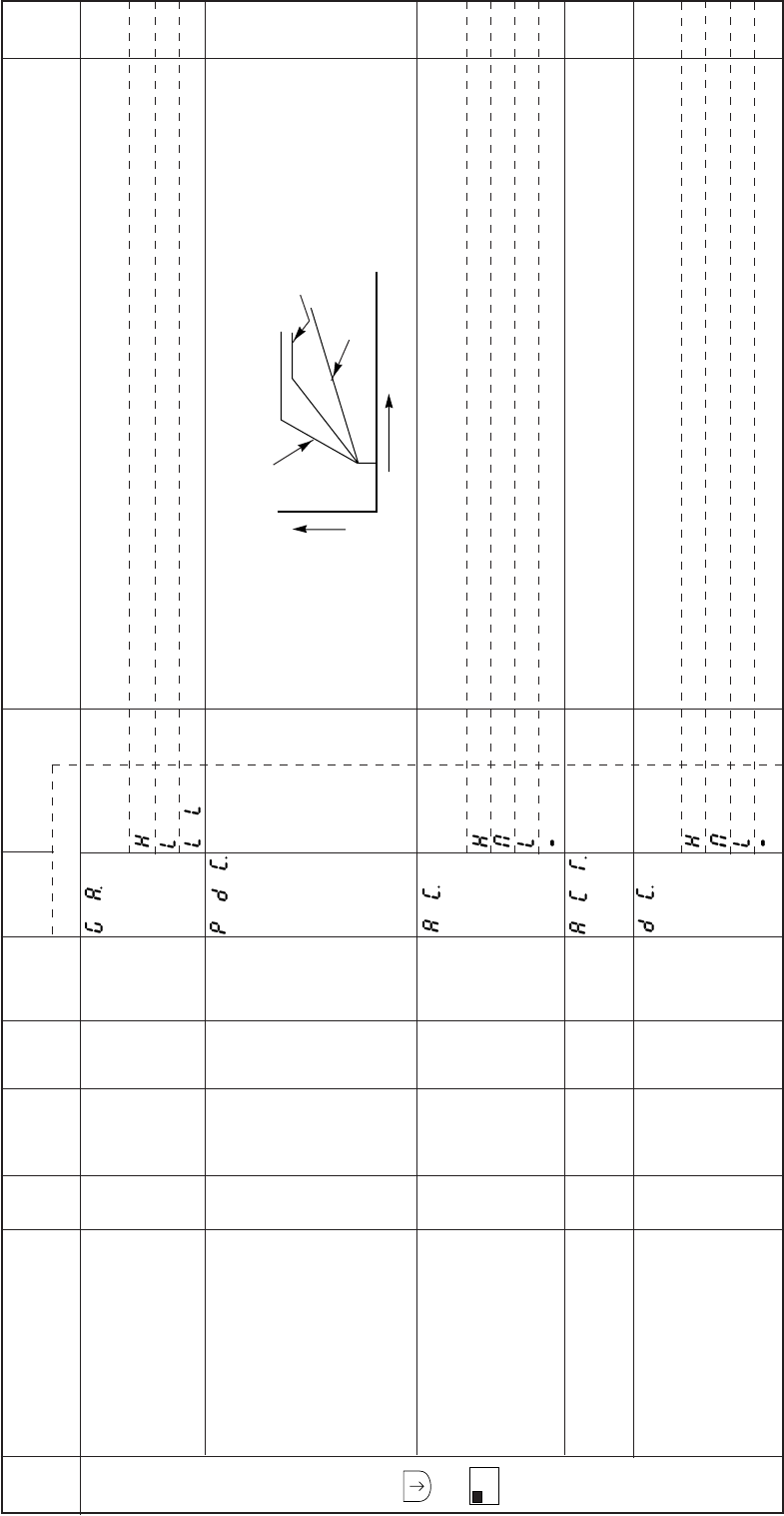
− 78 −
Mode
name Function name Oper
ability
Factory
setting Unit Setting
range Digital display
Function
name Setting Specification Ref.
page
The high/low gain can be set. Set with the following according to the sewing machine being used.
Sewing machine with large inertia.
Sewing machine with small inertia.
This is used when there is a slight vibration when stopping even when the gain is set to [L].
The size of the curve of the speed changes for the pedal toe down amount can be set. The speed
change curve will change from small to large according to the small => large of the set value.
The time for the sewing machine to reach the high speed after the pedal toe down or external run
signal (S1) is input can be set easily.
[H] : 100 mS
[M] : 140 mS
[L] : 240 mS
[–] : The time set in the next acceleration time ACT is used.
The acceleration time for the sewing machine to reach the high speed after pedal toe down or
external run signal (S1) ON can be set. This is valid when the acceleration time simple setting AC is
set to [–].
The deceleration time for the sewing machine to stop after returning to neutral from pedal toe down
or when the external run signalÅiS1Åjis turned OFF can be set easily.
[H] : 90 mS
[M] : 160 mS
[L] : 230 mS
[–] : The time set in the next deceleration time DCT is used.
A
mode
+
A
1-2
Gain high/low selection GA.
Pedal curve PDC.
Acceleration time AC.
simple setting
Acceleration time ACT.
Deceleration time DC.
simple setting
O
O
O
O
O
H
30
M
14
M
–
–
–
x10
msec
–
–
10 to 99
–
6 to 99
–
H
L
LL
**
H
M
L
–
**
H
M
L
–
**
**
Speed Set value-Large
Factory setting[30]
Set value-Small
Pedal toe down
–
–
–
–
–
–
–
–
–
–
–
–
–
–
–
–
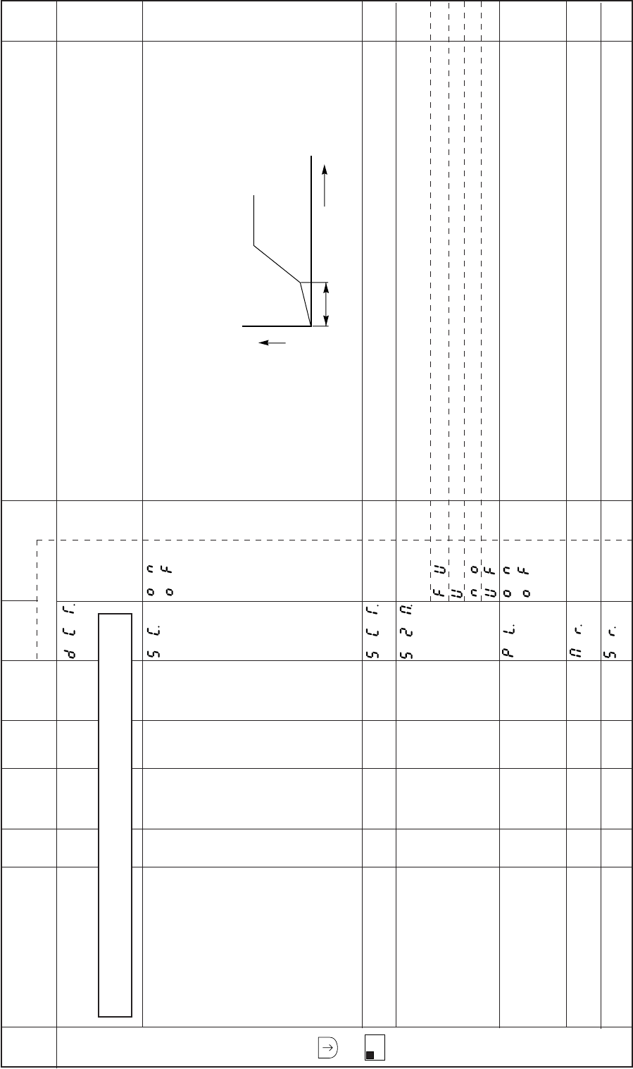
− 79 −
Mode
name Function name Oper
ability
Factory
setting Unit Setting
range Digital display
Function
name Setting Specification Ref.
page
The deceleration time for the sewing machine to stop after returning to neutral from pedal toe down
or when the external run signal (S1) is turned OFF can be set. This is valid when the deceleration
time simple setting DC is set to [–].
Normally use this at 350 milliseconds or less.
The speed change curve is accelerated slowly for the t time after pedal toe down or the external run
signal (S1) is turned ON, and then the sewing machine accelerates rapidly and enters the high
speed operation.
This is effective when carrying out one stitch sewing with the external run signal (S1) when automatic
operation function is set in the P mode.
The “t” time can set when S-character cushion is set to [ON].
The operation mode of the full heeling or S2 signal when the power is turned on or after thread
trimming is determined.
The presser foot lifting operation is entered.
The needle lifting operation is entered.
No operation.
The presser foot lifting operation after needle lifting is entered.
The speed setting is set so that the normal sewing machine shaft speed is constant, but by the [ON]
setting, it is possible to operate at the value which was set by the [MR], [SR] function.
This is effective when the motor pulley diameter is small, the V belt slips and the sewing machine
speed is unstable.
Set the diameter of motor pulley
When “PL” is “ON”, this function is valid.
Set the diameter of sewing machine pulley
When “PL” is “ON”, this function is valid.
A
mode
+
A
1-2
Deceleration time DCT.
S-character cushion SC.
S-character cushion SCT.
time setting
Full heeling S2 signal S2M.
operation mode when power
is turned on or after thread
trimming
Sewing machine shaft/ PL.
motor shaft speed
setting selection
Setting motor pulley MR.
diameter
Setting sewing machine SR.
pulley diameter
O
O
O
O
O
O
O
I6
OF
7
FU
OF
70
70
x10
msec
–
x10
msec
–
–
mm
mm
6 to 99
–
0 to 99
–
–
20 to 349
20 to 349
**
ON
OF
**
FU
U
NO
UF
ON
OF
***
***
Time
**
**
***
***
Speed
t
Caution
The factory setting [I6] refers to [I6x10 milliseconds=160 milliseconds].
–
–
–
–
–
–
–
–
–
–
–
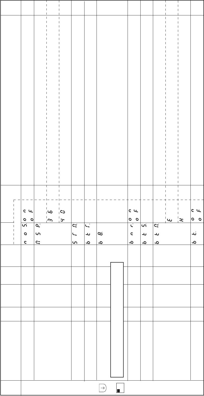
− 80 −
Mode
name Function name Oper
ability
Factory
setting Unit Setting
range Digital display
Function
name Setting Specification Ref.
page
Variable operation is possible when the detector has broken by setting to [ON] to invalidate the
detector. The positioning stop and thread trimming operations will not be possible.
The motor’s maximum speed can be set.
Set to [36]:3600 r/min
Not used
When machine will be stop,first priority become speed control
(Usually first priority to stop is stop angle.)
The brake time for stopping the sewing machine can be set.
Setting the angle to clear weak break.
Minimum setting angle is 0.2 degree.
Reducing the sound (noise) of weak brake.
The weak brake force can be set.
The weak brake force can be set for when stopping the sewing machine when the weak brake [BK]
is set to [ON].
Set to [E] : Brake that allows manual rotation.
Set to [H] : Strong brake
The weak brake validity can be set.
A
mode
+
A
1-2
No detector mode NOS.
Motor maximum speed MSP.
First priority stop => STM.
speed contro
Brake time BKT.
Weak brake angle B8.
Reduction of weak BNR.
brake sound
Weak brake force BKS.
Weak brake mode BKM.
Weak brake BK.
O
O
O
O
O
O
O
O
O
OF
36
OF
14
14
ON
99
E
OF
–
x100
r/min
–
x10
msec
x0.1
Degree
–
%
–
–
–
–
–
0 to 99
4 to 500
–
0 to 99
–
–
ON
OF
36
40
ON
OF
**
***
ON
OF
**
E
H
ON
OF
**
***
**
–
–
–
–
–
–
–
–
–
–
–
–
–
Caution
The factory setting [I4] refers to[I4x0.1 degree=1.4 degree].
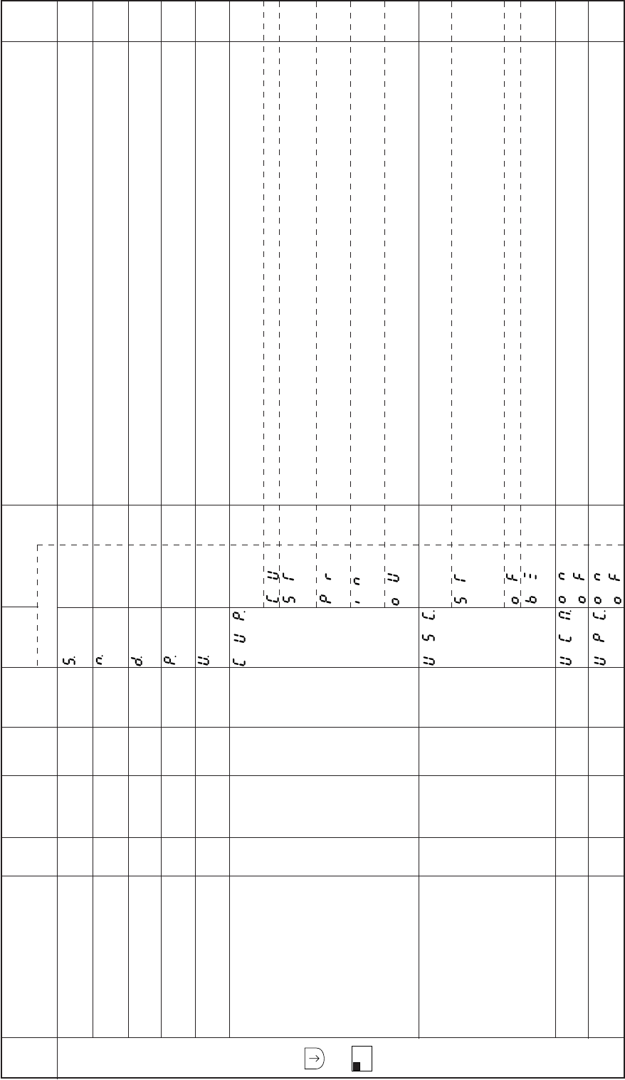
− 81 −
Mode
name Function name Oper
ability
Factory
setting Unit Setting
range Digital display
Function
name Setting Specification Ref.
page
Display the round per minute of running sewing machine.
Setting the number of down counter.
Display the number of current down counter.
Setting the number of up counter.
Display the number of current up counter.
Selection of count up condition.
After thread trimming is finished.
The number of sewing stitch become “N”
(”N” have to be set at “CNU”)
The number of trimming times become “N”
(”N” have to be set at “PRN”)
When output signal “O1” become ON.
(”IO1” have to be set to input signal on the program mode C.)
When output signal “O1” become ON.
(”O1” have to be set to output function on “O1” of the program mode C.)
Selection of operation count over.(Up counter)
Control panel buzzes and running is prohibited after trimming with buzzer sound. And then when
counter clear key “CCL” is pressed, sewing become possible. (Buzzer will stop after a while.)
(Factory is possible to continue without buzzer sound.)
Sewing is possible to continue without buzzer sound.
Sewing is possible to continue with buzzer sound.
(Buzzer will stop after a while.)
When sewing pattern is changed, it clear “up counter”. (UCM=ON)
The up counter is valid. (UPC=ON)
B
mode
+
B
SL
Display sewing speed S.
Down counter setting N.
count amount
Down counter display D.
count amount
Up counter setting P.
count amount
Up counter display U.
count amount
Up counter the selection CUP.
of setting mode
Up counter the selection USC.
of counter operation
Up counter changing UCM.
sewing pattern
Up counter valid/invalid UPC.
O
O
O
O
O
O
O
O
O
–
99
99
99
0
CU
ST
OF
OF
r/min
–
–
–
–
–
–
–
–
–
0 to 9999
0 to 9999
0 to 9999
0 to 9999
–
–
–
–
****
****
****
****
****
CU
ST
PR
IN
OU
ST
OF
BZ
ON
OF
ON
OF
****
****
****
****
****
–
–
–
–
–
–
–
–
–
–
–
–
–
–
–
–
–
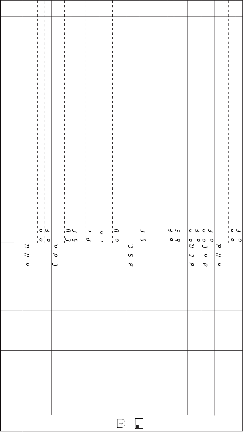
− 82 −
Mode
name Function name Oper
ability
Factory
setting Unit Setting
range Digital display
Function
name Setting Specification Ref.
page
B
mode
+
B
SL
The UP counter operation, after counting over.
(it is valid, when [USC] is set to “OF,”BZ”.)
The display shows the setting number and the counting is stopped.
The display shows setting number and the counting is continued.
Selection of count condition.
After thread trimming is finished.
The number of sewing stitch become “N”
(”N” have to be set at “CNU”)
The number of trimming times become “N”
(”N” have to be set at “PRN”)
When input signal “O1” become ON.
(”IO1” have to be set to input signal on the program mode C.)
When output signal “O1” become ON.
(”O1” have to be set to output function on “O1” of the program mode C.)
Selection of operation at count over. (Down counter)
Control panel buzzes and running is prohibited after thread trimming with buzzer sound. And then
when counter clear key “CCL” is pressed, buzzer and sewing become possible. (Buzzer will stop
after a while.)
(Factory is setting of counter clear key is “P” key on control panel.)
Sewing is possible to continue without buzzer sound.
Sewing is possible to continue with buzzer sound.
(Buzzer will stop after a while.)
When sewing pattern is changed, it clear “down counter”. (DCM=ON)
The down counter is valid. (DNC=ON)
The down counter action, after counting over.
(It is valid, when [DSC] is set to “OF”, ”BZ”.)
The display shows “0” and the counting is stopped.
The display shows “–“ and the counting is continued.
Up counter operation NXU.
after counting over
Down counter CDN.
the selection of setting mode
Down counter DSC.
the selection of counter operation
Down counter changing DCM.
sewing pattern
Down counter DNC.
valid/invalid
Down counter operation NXD.
after counting over
O
O
O
O
O
O
OF
CU
ST
OF
OF
OF
–
–
–
–
–
–
–
–
–
–
–
–
ON
OF
CU
ST
PR
IN
OU
ST
OF
BZ
ON
OF
ON
OF
ON
OF
–
–
–
–
–
–
–
–
–
–
–
–
–
–
–
–
–
–
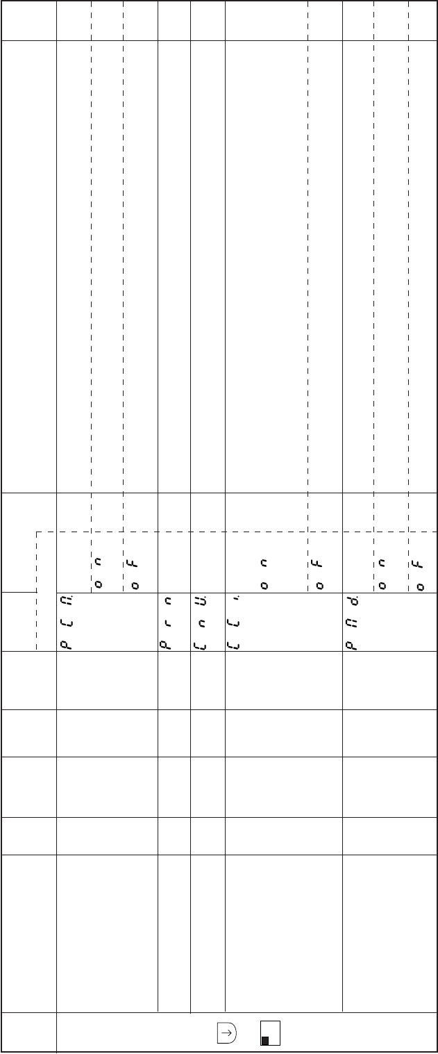
− 83 −
Mode
name Function name Oper
ability
Factory
setting Unit Setting
range Digital display
Function
name Setting Specification Ref.
page
B
mode
+
B
SL
When power switch is turned on,
Up counter is clear (zero) and down counter is set the setting number.
Both counter keep previous amount.
When “CUP” and “CDN” are PR, trimming times “N” is set.
When “CUP” and “CDN” are ST, number of stitch “N” is set.
Modification of count amount.
When input function “IO1” is turn on, it become count up.
When input function “IO2” is turn on, it become count down.
(Input function can set input signal on program mode “C”.)
Modification is prohibited.
Selection display mode, when power switch is turned on.
When power switch turn on, display shows previous condition.
(Keep previous condition)
When power switch turn on, display shows normal mode.
Counter condition turning PCM.
on power switch
Setting Thread trimming PRN.
times “N”
Setting Number of CNU.
stitches “N”
Count modification CCI.
(to use IO1,IO2)
Display condition turning PMD.
on power switch
O
O
O
O
O
OF
0
1
OF
OF
–
times
stitches
–
–
–
0 to 99
1 to 99
–
–
ON
OF
**
**
ON
OF
ON
OF
**
**
–
–
–
–
–
–
–
–
–
–
–
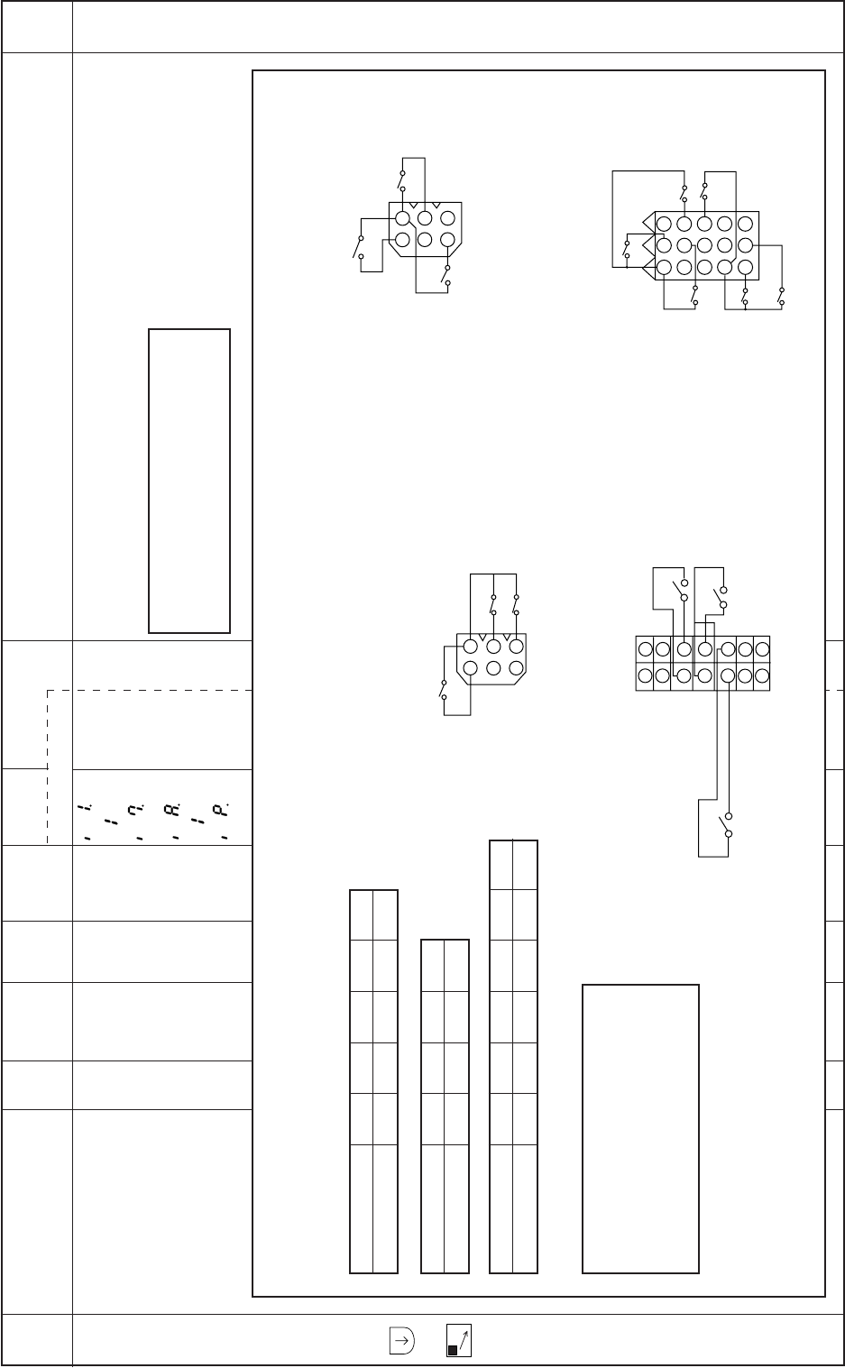
− 84 −
Mode
name Function name Oper
ability
Factory
setting Unit Setting
range Digital display
Function
name Setting Specification Ref.
page
C
mode
+
C
Selection of input
signal function I1. to I7.
IA. to IP.
X – – – ****** The input functions of each signal I1 to I4 and IA to IP can be selected from 60 types of functions.
1. Refer to the C mode input signal setting table of the pages 126 to 131.
2. Refer to the Conception figure of input and output customization of the page 132 to 134.
Caution
Input signal I3 is not available.
Set CPK to ON when using the input signal I6.
Set CKK to ON when using the input signal IC.
–
–
–
–
Caution
Table of each input signal and connector pin connection and factory setting correspondence
Input signal[IP] is [CCL] hey on control panel.
Input signal IA IB IC ID IE
Factory setting PSU PSD S0 TL S7
Input signal IF IG IH II
Factory setting F S1 S2 S3
Input signal I1 I2 I4 I5 I6 I7
Factory setting IO1 IO1 NO NO F BTL
Caution
Input signals [14, 15, 16, 17] are dual port of
input and output.
So when these input signals will be used,
output functions of O4, O5, O6 and O7 have
to be set to “NO”.
321
654
987
121110
15
1413
147
136
125
114
103
92
81
1
2
3
4
5
6
1
2
3
4
5
6
II
IG
IH
(Lever connector)
IG : S1 (Variable speed run signal)
IH : S2 (Thread trimmer signal)
II : S3 (Presser foot lifter signal)
IB
IA
IC
(Option A connector)
IA : PSU (Needle UP position priority stop signal)
IB : PSD (Needle DOWN position priority stop signal)
IC : S0 (Low speed run signal)
I5
I4
I1
I2
I6
I7
(Option B connector)
I1 : 1O1 (Signal output to virtual output 1)
I2 : 1O1 (Signal output to virtual output 1)
I4 : NO (No setting)
I5 : NO (No setting)
I6 : F (Presser foot lifter signal)
I7 : BTL (Start/end tacking cancel signal)
(Sewing machine connector)
ID : TL (Thread trimmer cancel signal)
IE : S7 (Backstitching during run signal)
IF : F (Presser foot lifter signal)
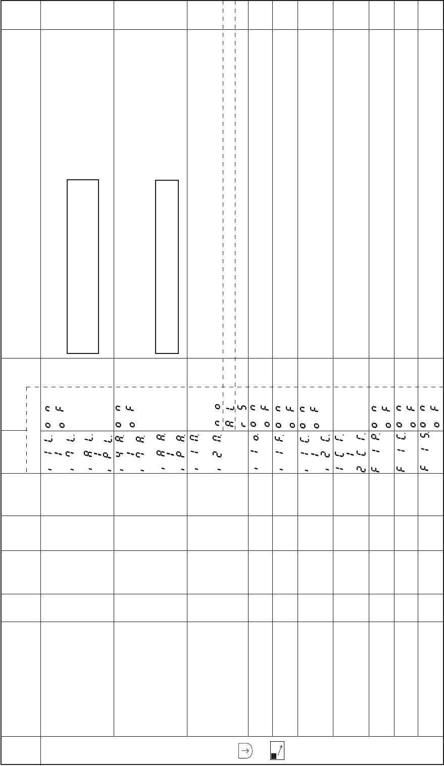
− 85 −
Mode
name Function name Oper
ability
Factory
setting Unit Setting
range Digital display
Function
name Setting Specification Ref.
page
C
mode
+
C
The input logic of each Input signal I1 to I7 and IA to IP is reversed.
If each input signal I4 to I7 and IA to IP performs OFF =>(1) ON=>OFF=>(2) ON=>OFF=>(3)
ON=>OFF the signal will stay ON at (1),stop (turn OFF) at (2), and will turn ON again at (3). (iThis is
hereafter referred to alternate operation.)
The operation mode of each input signal I1 and I2 can be selected.
Normal operation
Alternating operation.
RS F/F (Flip-Flop) operation.
When sewing machine is running, input signal[I1] is not accepted
This function is valid, only [I1M] set [AL] or [RS].
When [I1M] set [AL] on program mode “C”, the alternate operation of input [I1] sets virtual output
[OT3] to alternative output.
F/F (Flip Flop) operation of input signal [I1] and [I2] is cleared by thread trimming operation.
When above setting (I1C,I2C) is valid, these delay timer is set.
The input signal I1 virtual F/F (flip-flop) operation is tuned ON when power is turned ON.
It is only valid, when [I1M] function is set to “AL” or “RS”.
The input signal I1 virtual F/F (flip-flop) operation is turned OFF when the sewing start No. of stitches
RLN setting is completed.
The input signal I1 virtual F/F (flip-flop) operation is turned ON when the tacking starts or after thread
trimming.
Input signal logical changeover
function
I1L. to I7L.
IAL. to IPL.
Input signal alternating operation
I4A. to I7A.
IAA. to IPA.
Setting the function for I1 and I2
I1M. to I2M.
Special setting for input signal “I1”
(Neglecting of signal) I1O.
Special setting for input I1F.
signal “I1” is ON
RS F/F clear setting I1C. to I2C.
RS F/F delay time setting
1CT. to 2CT.
Input signal I1 virtual F1P.
F/F circuit operation 1
Input signal I1 virtual F/F F1C.
circuit operation 2
Input signal I1 virtual F/F F1S.
circuit operation 3
X
X
X
O
X
X
O
X
X
X
OF
OF
AL
OF
OF
OF
0
OF
OF
OF
–
–
–
–
–
–
x100
msec
–
–
–
–
–
–
–
–
–
0 to 99
–
–
–
ON
OF
ON
OF
NO
AL
RS
ON
OF
ON
OF
ON
OF
**
ON
OF
ON
OF
ON
OF
**
Caution
The function I3L is not available.
Set CPK to ON when using the function I6L.
Caution
Set CPK to ON when using the function I6A.
–
–
–
–
–
–
–
–
–
–
–
–
–

− 86 −
Mode
name Function name Oper
ability
Factory
setting Unit Setting
range Digital display
Function
name Setting Specification Ref.
page
C
mode
+
C
Set condition RS F/F of I1 and I2
When [I1M] and [I2M] is set to [RS], it is valid.
RS F/F of I1 is set by I1, RS F/F of I2 is set by I2.
After thread trimming operation (stop to up position.)
When motor start, RS F/F will be set.
When motor stop, RS F/F will be set.
When sewing start, after thread trimming.
When start tacking or condensed stitch was finished.
(When condensed stitch is not set, it is invalid)
Reset condition RS F/F of I1 and I2
When [I1M] and [I2M] is set to [RS], it is valid.
RS F/F of I1 is reset by I6, RS F/F of I2 is reset by 17.
When thread trimming is done (stop to up position.)
When motor start, RS F/F will be reset.
When motor stop, RS F/F will be reset.
When sewing start, after trimming.
When start condensed stitch was finished.
(When condensed stitch is not set, it is invalid.)
When sewing machine sew the setting stitch after set RS F/F, it will be reset. (R1N, R2N)
When [R1R] or [R2] set [NC], the number of stitch is set by this counter.
The output functions of each output signal OA to OD,OF,OJ to OK and O1 to O7 can be selected
from 37 types of functions.
1. Refer to the C mode input signal setting table of the pages I68 to I71.
2. Refer to the Conception figure of input and output customization of the page I74 to I76.
Set condition of RS F/F
for I1 and I2
R1S. to R2S.
Reset condition of RS F/F
for I1 and I2
R1R. to R2R.
RS F/F reset stitch amount
for I1 and I2
R1N. to R2N.
Selection of output signal function
OA. to OD.
OF.
O1. to O7.
OJ. to OK.
X
X
O
X
IN
IN
3
*
–
–
Stitches
–
–
–
0 to 99
–
IN
T
R
S
TR
SB
IN
T
R
S
TR
SB
NC
**
***
**
***
Caution
Output signal OE is not available.
Set CPK to ON when using the function O6.
–
–
–
–
–
–
–
–
–
–
–
–
–
–
–
–
–
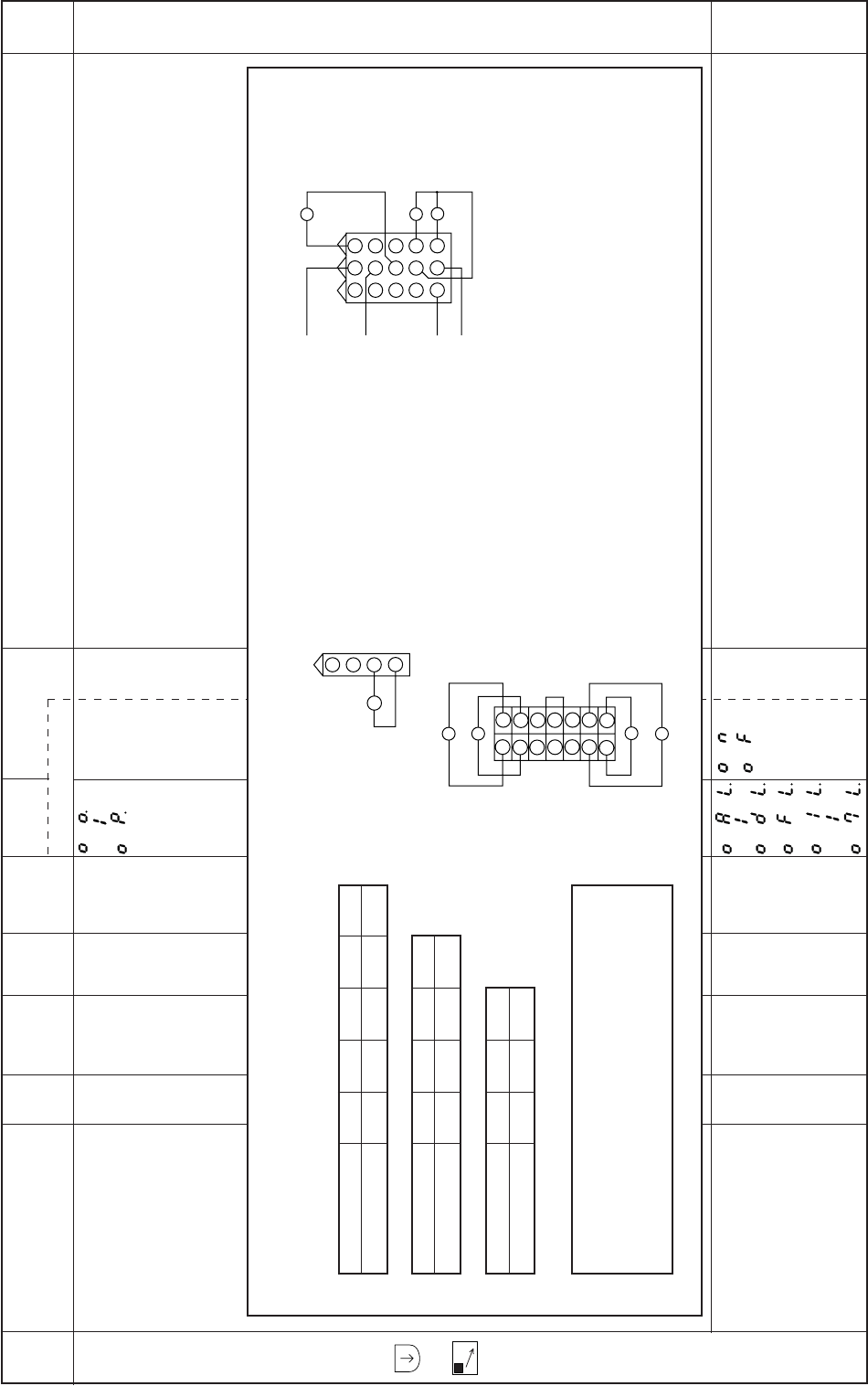
− 87 −
Mode
name Function name Oper
ability
Factory
setting Unit Setting
range Digital display
Function
name Setting Specification Ref.
page
C
mode
+
C
The output functions of each output signal OO to OP can be selected from 37 types of functions.
1. Refer to the C mode input signal setting table of the pages 126 to 131.
2. Refer to the Conception figure of input and output customization of the page 132 to 134.
The output logic of each output signal OA to OD, OF and O1 to O7 is reversed.
Selection of output signal function
OO. to OP.
Output signal logical
changeover function
OAL. to ODL.
OFL.
O1L. to O7L.
X
X
*
OF
–
–
–
–
***
ON
OF
***
(Option B connector)
O1 : OT1 (Virtual output)
O2 : NCL (Needle cooler output)
O3 : TF (TF output)
O4 : NO (No setting)
O5 : NO (No setting)
O6 : NO (No setting)
O7 : NO (No setting)
Caution
Table of each output signal and connector pin connection and factory setting correspondence.
Output signal OA OB OC OD OF
Factory setting T W B L FU
Output signal O1 O2 O3 O4
Factory setting OT1 NCL TF NO
Output signal O5 O6 O7
Factory setting NO NO NO
Caution
Output[O4,O5,O6,O7] are not solenoid output signal.
Also these signal are dual port of input and output.
So when these output signal will be used, input signal have
to be set to “OF”.
714
613
512
411
310
29
18
3
6
9
2
5
8
1
4
7
121110
151413
1
2
3
4
OF (Presser foot lifter connector)
OF : FU (Presser foot lifter output)
OB
OA
OD
OC
(Sewing machine connector)
OA : T (Thread trimmer output)
OB : W (Wiper output)
OC : B (Backstitch output)
OD : L (Thread release output)
O4
O5
O7
O6
O1
O2
O3
–
–
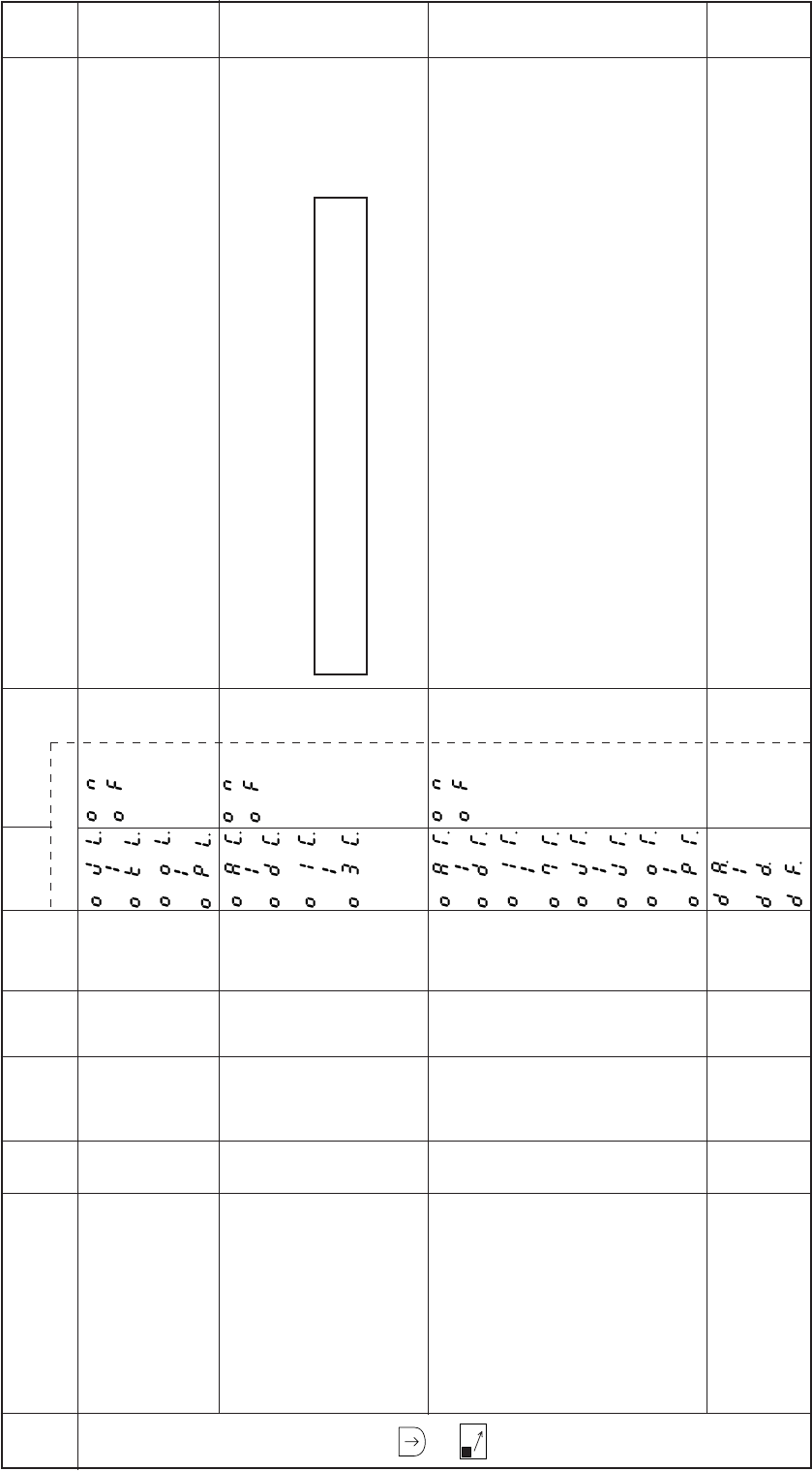
− 88 −
Mode
name Function name Oper
ability
Factory
setting Unit Setting
range Digital display
Function
name Setting Specification Ref.
page
C
mode
+
C
The output logic of each output signal OJ to OK, and OO to OP is reversed.
Each output is output with full wave immediately after output starts, and then is reduced to half-wave
output for each output signal OA to OD and O1 to O3. (Chopping control)
The full wave output time can be set with the full wave time [PO] function for each output.
In each output signal OA to OD, OJ to OK, OO to OP and O1 to O7, each output is forcibly turned
OFF after the time set in the OFF timer is passed.
The OFF timer set time can be set with each output’s forced OFF timer [OTT] function.
In each output signal OA to OD and OF the delay time to when each output is started can be set.
Each delay time can be set in 20ms intervals.
Output signal logical
changeover function
OJL. to OKL.
OOL. to OPL.
Output chopping function
OAC. to ODC.
O1C. to O3C.
Output signal forced
OFF function
OAT. to ODT.
O1T. to O7T.
OJT. to OKT.
OOT. to OPT.
Output signal delay
time setting function
DA. to DD.
DF.
X
X
X
X
OF
OF
OF
0
–
–
–
x20
msec
–
–
–
0 to 08
ON
OF
ON
OF
ON
OF
******
Caution
Output signal [O4, O5, O6, O7] are chopping function is not available.
–
–
–
–
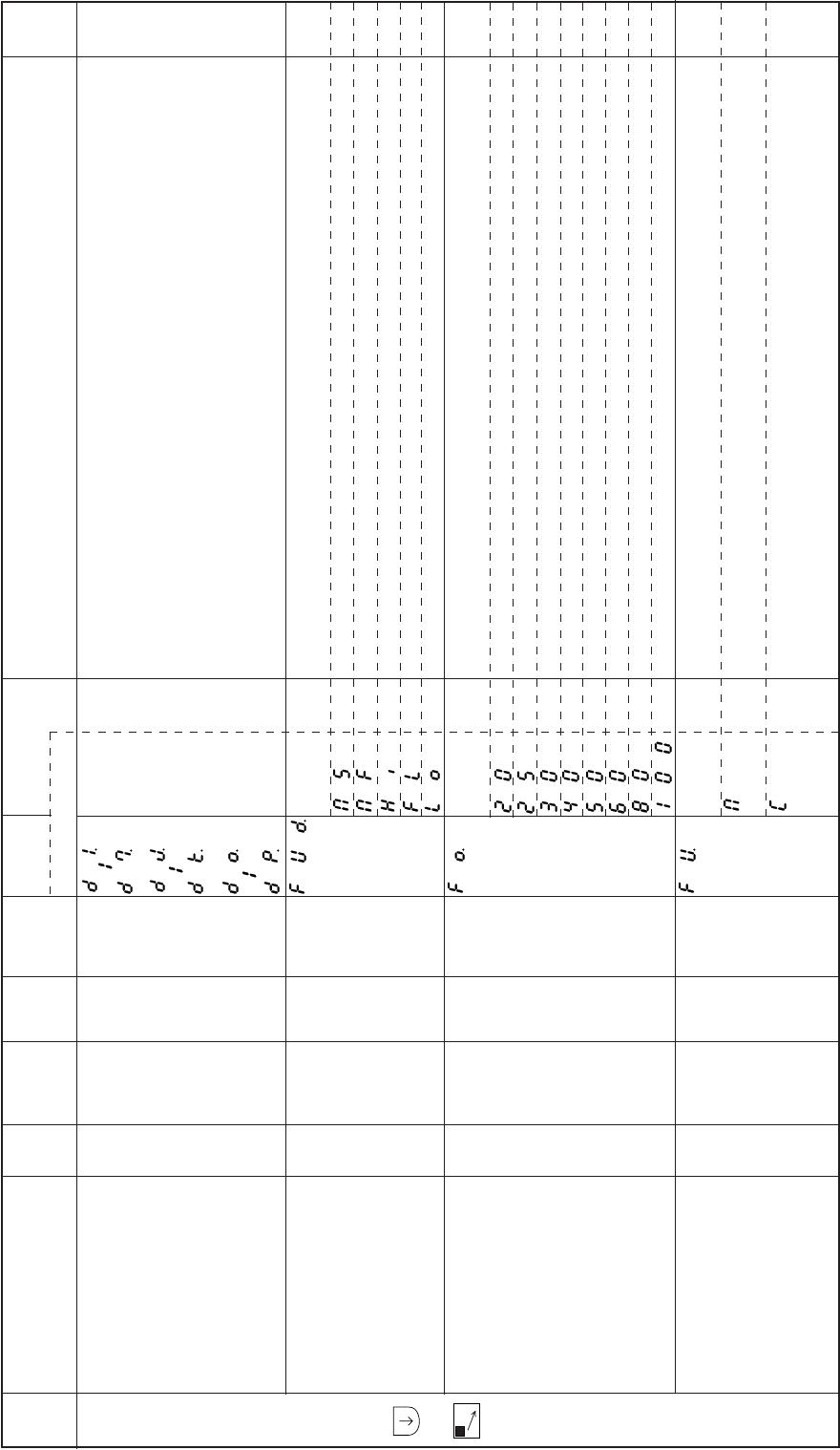
− 89 −
Mode
name Function name Oper
ability
Factory
setting Unit Setting
range Digital display
Function
name Setting Specification Ref.
page
C
mode
+
C
In each output signal OJ to OK, OO to OP and O1 to O7, the delay time to when each output is
started can be set.
Each delay time can be set in 2 ms intervals.
The chopping output duty during holding after the presser foot lifter output FU lifting operation can be
set.
Set to [MS] : 4 ms ON/OFF 50 %duty
Set to [MF] : 2 ms ON/OFF 50 %duty
Set to [HI] : 4 ms ON, 2 ms OFF, 66 %duty
Set to [FL] : 100 % (full wave)
Set to [LO] : 2 ms ON,4 ms OFF 33 %duty
The full wave output time of the presser foot lifter output FU can be set.
Set to [20] : 200 ms
Set to [25] : 250 ms
Set to [30] : 300 ms
Set to [40] : 400 ms
Set to [50] : 500 ms
Set to [60] : 600 ms
Set to [80] : 800 ms
Set to [100] : 1000 ms
The operation mode of presser foot lifter momentary FUM is set. This is valid when presser foot lifter
momentary FUM is set to [ON] in the P mode.
The presser foot lifter operation is continued after full heeling or after thread trimmer with external
thread trimmer signal S2.
The presser foot lifter operation is continued during the timer time after full heeling or after thread
trimming with external thread trimmer signal S2. Then the presser foot lifter is lowered.
The timer can be adjusted with timer setting FCT in the P mode.
Output signal delay time
setting function
D1. to D7.
DJ. to DK.
DO. to DP.
Presser foot lifter output FUD.
chopping duty
Presser foot lifter FU full FO.
wave output time
Presser foot lifter FU FU.
momentary mode
X
X
X
X
D1=10
MF
50
M
msec
–
x10
msec
–
***
MS
MF
HI
FL
LO
20
25
30
40
50
60
80
100
M
C
***0 to 510
–
–
–
–
–
–
–
–
–
–
–
–
–
–
–
–
–
–
–
–
–
–
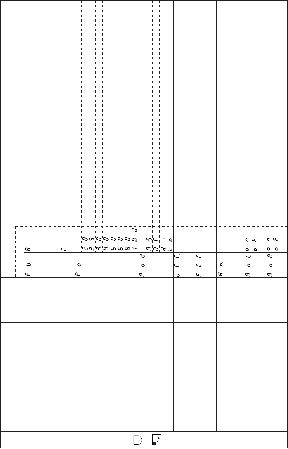
− 90 −
Mode
name Function name Oper
ability
Factory
setting Unit Setting
range Digital display
Function
name Setting Specification Ref.
page
C
mode
+
C
The presser foot lifter operates with full heeling or when the external signal (S2, F) turns ON, and
then the presser foot lifter.
Lower when full heeling, light heeling or external signal (S2,F) turns on.
The presser foot lifter will rise if these signal is turned ON again.
(Alternate operation)
The timer operates in the same manner as [C] setting. However, after the presser foot lifter lowers,
the operation will be alternate as with the [A] setting.
The full wave output time of each output signal OA to OD and O1 to O7 can be set.
Set to [20] : 200 ms
Set to [25] : 250 ms
Set to [30] : 300 ms
Set to [40] : 400 ms
Set to [50] : 500 ms
Set to [60] : 600 ms
Set to [80] : 800 ms
Set to [100] : 1000 ms
Setting output chopping duty, except FU output.
Set to [MS] : 4ms ON/OFF 50%.
Set to [MF] : 2ms ON/OFF 50%.
Set to [HI] : 4ms ON, 2ms OFF, 66% duty.
Set to [LO] : 2ms ON, 4ms OFF, 33% duty.
The timer that forcibly turns off output signals OA to OD and O1 to O7 can be set.
The timer from the time when the presser foot lifter output is turned ON to the time when it is turned
OFF.
(when FUM operation mode FU [C] or[T] is set can be set.)
Select input function to the logic input [AND].
Input function is select on “Input/output function for signal on C mode setting” (pages 126 to 131)
Refer to “ The composition figure of input and output customization” about [AND] setting. (Pages 132
to 134)
[AND] input logic is set to opposite
Refer to “The composition figure of input and output customization” about [AND] setting. (Pages 132
to 134)
[AND] input is set to alternative.
Refer to “The composition figure of input and output customization” about [AND] setting. (Pages 132
to 134)
Presser foot lifter FU FU.
momentary mode
Full wave output time PO.
for each output
Output chopping duty POD.
except of FU output
Forced OFF timer setting OTT.
function for each output
FUM operation mode FCT.
timer setting function
Logic [AND] input/selecting AN.
input function
Logic[AND] input setting ANL.
Hi / Low logic
Logic[AND] input ANA.
Alternate
X
O
O
O
O
X
X
X
M
50
MF
12
12
NO
OF
OF
–
x10
msec
–
sec
sec
–
–
–
–
–
–
1 to 24
1 to 99
–
–
–
A
T
20
25
30
40
50
60
80
100
MS
MF
HI
LO
**
**
***
ON
OF
ON
OF
**
**
***
–
–
–
–
–
–
–
–
–
–
–
–
–
–
–
–
–
–
–
–
–
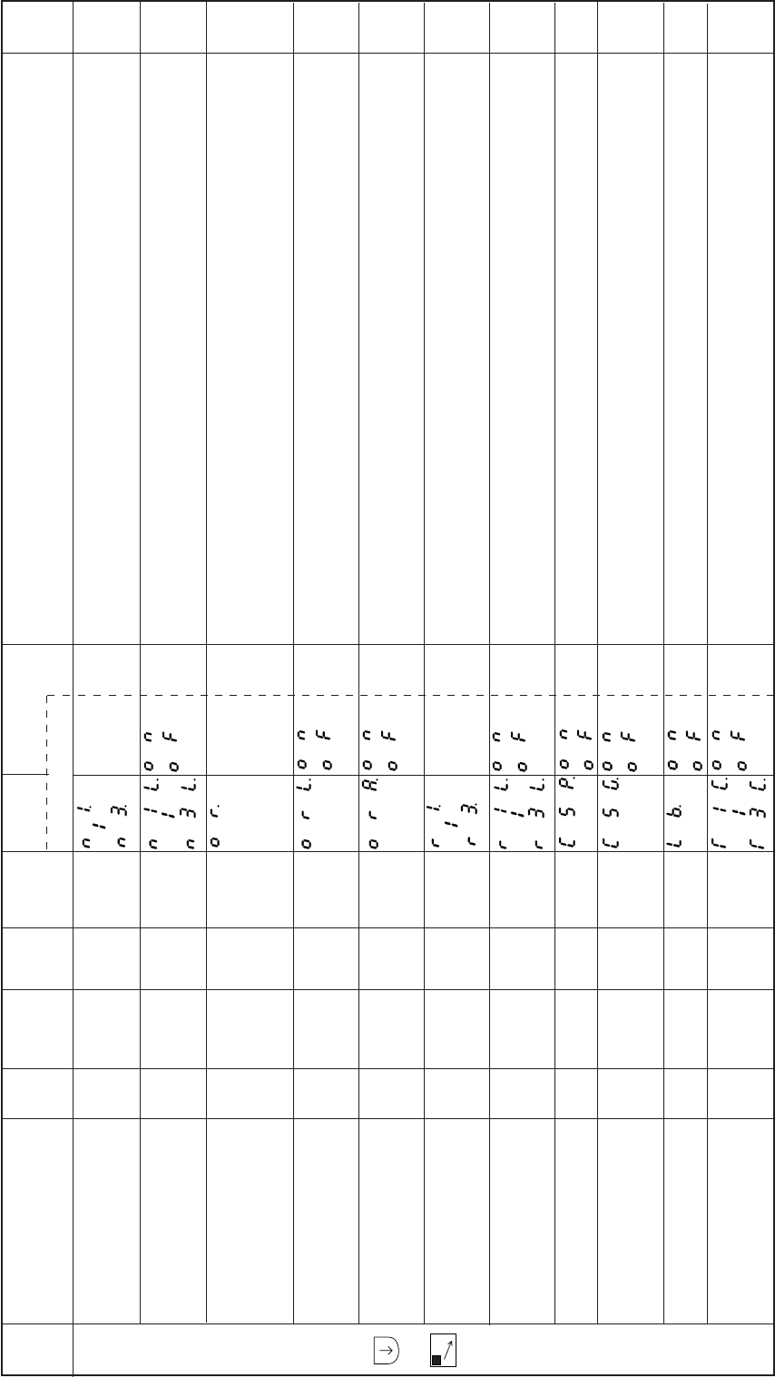
− 91 −
Mode
name Function name Oper
ability
Factory
setting Unit Setting
range Digital display
Function
name Setting Specification Ref.
page
C
mode
+
C
Select output function of [AND 1/2/3]
Refer to “The composition figure of input and output customization” about [AND] setting. (Pages 132
to 134)
[AND 1/2/3] output logic is set to opposite
Refer to “The composition figure of input and output customization” about [AND] setting. (Pages 132
to 134)
Select input function to logic input [OR]
Input function is select on “Input/output function for signal on C mode setting” (pages 126 to 131)
Refer to “The composition figure of input and output customization” about [OR] setting. (Pages 132
to 134)
[OR] input logic is set to opposite.
Refer to “The composition figure of input and output customization” about [OR] setting. (Pages 132
to 134)
[OR] input logic is set to Alternate.
Refer to “The composition figure of input and output customization” about [OR] setting. (Pages 132
to 134)
Select output function of [OR 1/2/3]
Refer to “The composition figure of input and output customization” about [OR] setting. (Pages 132
to 134)
[OR 1/2/3] output logic is set to opposite.
Refer to “The composition figure of input and output customization” about [OR] setting. (Pages 132
to 134)
Set variable speed command for digital input. (I1, I2, I6, I7)
High speed is set to [H] on program mode “P”. (CSP=ON.CSG=OFF)
Set variable speed command for digital input. (I1, I2, I6, I7)
High speed is set to [H] on program mode “P”.
To use gray code. (3, 2, 1, 0)= (I6, I7, I2, I1). (CSP=ON, CSG=ON)
Thread release output L will turn ON even while backstitch output B is ON.
Virtual outputs OT1 to OT3 will be turned OFF forcibly after the OFF timer set time has passed.
The OFF timer set time can be set with the virtual output OFF timer setting function [T1T to T3T].
Logic [AND 1/2/3] output
selecting output function
N1. to N3.
Logic [AND 1/2/3] output
setting of Hi/Low logic
N1L. to N3L.
Logic[OR] input selecting
input function
OR.
Logic [OR] input setting
of Hi/Low logic
ORL.
Logic[OR] input Alternate
ORA.
Logic [OR 1/2/3] output
selecting output function
R1. to R3.
Logic[OR 1/2/3] output
setting of Hi/Low logic
R1L. to R3L.
Variable speed command
for digital input CSP.
Variable speed command
for digital input
(Gray code) CSG.
Thread release +
backstitch output LB.
Virtual output (OT1 to OT3)
forced OFF function
T1C. to T3C.
X
X
X
X
X
X
X
X
X
O
O
HI
OF
NO
OF
OF
NO
OF
OF
OF
OF
OF
–
–
–
–
–
–
–
–
–
–
–
–
–
–
–
–
–
–
–
–
–
–
***
ON
OF
***
ON
OF
ON
OF
***
ON
OF
ON
OF
ON
OF
ON
OF
ON
OF
***
***
–
–
–
–
–
–
–
–
–
–
–
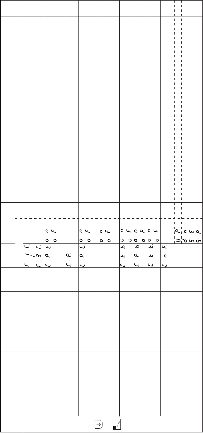
− 92 −
Mode
name Function name Oper
ability
Factory
setting Unit Setting
range Digital display
Function
name Setting Specification Ref.
page
C
mode
+
C
The timer time for forcibly turning OFF virtual outputs OT1 to OT3 can be set.
Feed pulse [CP] is invalid.
When feed pulse will be used, set this function to “CF”
This signal output is from the same pin of “I6” and “O6”.
Setting the number of pulse [CP]. After changing this number, turn on power switch again.
The prohibited angle section of pulse generated can be set from UP position.
The prohibited angle of pulse generated is 60 degree from the setting position (angle).
Panel switch operation ([M], [A,1-2], [B,SL], [C,<= =]. [D,= =>] key operations)
during the normal mode, tacking mode and pattern mode will not be possible.
However, changeover into each mode will be possible.
Output signal “CKD” is prohibited during backtack term.
Output signal “CP” is prohibited during backtack term.
Output signal “CKD” is prohibited.
Selection F key function.
Display Up counter amount
Display Down counter amount
Display stitch amount of sensor
Display routine speed of sewing machine.
Forced OFF timer setting
function for virtual outputs
(OT1 to OT3) T1T. to T3T.
Feed pulse output (CP) CPK.
cancel function
Setting CP pulse amount CP.
Prohibited angle of CPC.
output CP pulse
Panel switch PSW.
operation prohibit
CKD output cancel CKB.
during backtack trem
CP output cancel during CPB.
backtack term
CKD output cancel CKK.
F key function CNF.
on control panel
O
O
O
O
O
O
O
O
O
99
ON
32
OF
OF
OF
OF
ON
SE
x10
msec
–
–
–
–
–
–
–
–
0 to 99
–
1 to 99
–
–
–
–
–
–
**
ON
OF
**
ON
OF
ON
OF
ON
OF
ON
OF
ON
OF
UP
DN
SE
SP
**
**
–
–
–
–
–
–
–
–
–
–
–
–
–
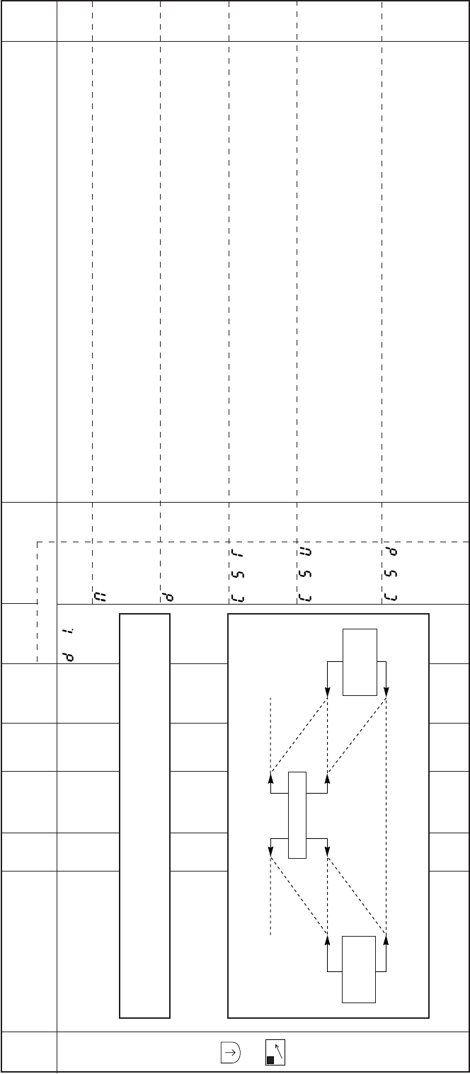
− 93 −
Mode
name Function name Oper
ability
Factory
setting Unit Setting
range Digital display
Function
name Setting Specification Ref.
page
D
mode
+
D
The operation mode during tacking is determined.
During start tacking, even if the pedal is returned to neutral or the external run signal (S1) is turned
OFF, the stitching will continue to the last tack process, and then will stop.
Stitching will continue in the same manner for end tacking, and the needle will be lifted after thread
trimming.
The tacking speed will change according to the pedal toe down amount only during start tacking.
(the maximum speed is the start tacking speed N.)
The sewing machine will stop if the pedal is returned to neutral or external signal turned OFF during
start tacking.
The sewing machine will stop for a set time at each tack corner even with pedal toe down or if the
external run signal (S1) is ON.
The stop time can be adjusted with [CT].
This is used to accurately tack.
The sewing machine will stop for a set time at each tack corner even with pedal toe down or if the
external run signal (S1) is ON.
The sewing machine stops at the UP position irrespective of the position.
The stop time can be adjusted with [CT].
This is used to accurately tack.
The sewing machine will stop for a set time at each tack corner even with pedal toe down or if the
external run signal (S1) is ON.
The sewing machine stops at the DOWN position irrespective of the position.
The stop time can be adjusted with [CT].
This is used to accurately tack.
Operation mode D1.
during tacking
OM––
M
D
CST
CSU
CSD
Temporary
stop Temporary
stop
Caution
Set the start and end tack type, and number of stitches in the tacking mode
before setting the functions in the D mode.
–
–
–
–
–
–
Temporary stop
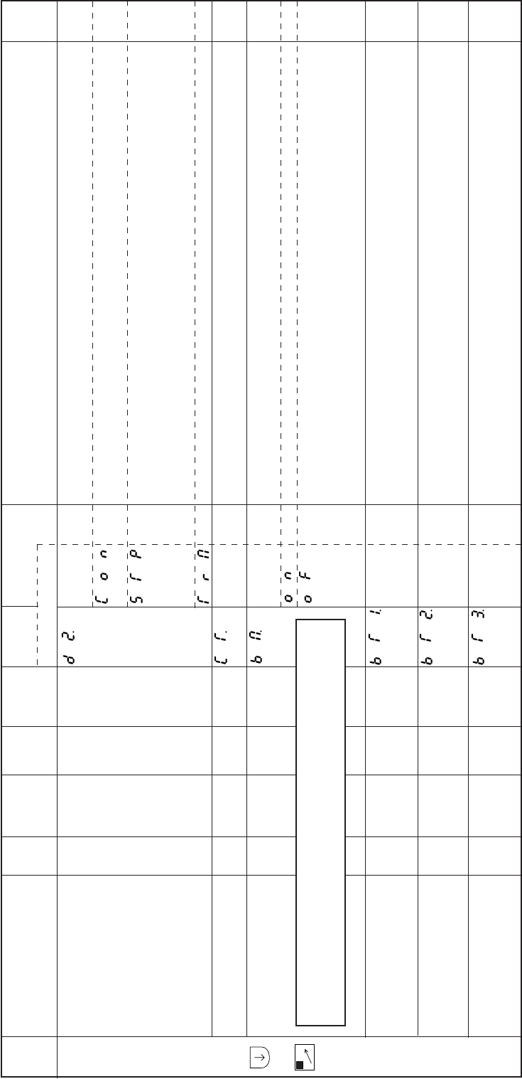
− 94 −
Mode
name Function name Oper
ability
Factory
setting Unit Setting
range Digital display
Function
name Setting Specification Ref.
page
D
mode
+
D
The operation mode during the completion of start tack is determined.
If the pedal is toed down or the external run signals (S0, S1) are ON when start tacking is completed,
the next straight line stitching will begin.
Even if the pedal is toed down or the external run signals (S1) turned ON when start tacking is
completed, the sewing machine will stop.
The next straight line stitching will start when the pedal is toed down for neutral again, or when the
external run signals (S1) is turned OFF to ON.
The thread is trimmed when start tacking is completed. This is used for continuous tack stitch.
The stop time at each corner during tacking can be set when [CST] in operation mode D1 is set.[CSU],
[CSD]
The backstitch solenoid operation timing can be set to align the tacking.
Set to [ON] : Tacking speed less than 1000 rotations.
Set to [OFF] : Tacking speed 1000 rotations or more.
By finely adjusting the backstitch solenoid operation timing of start tacking from forward to reverse,
the no. of stitches can be compensated.
The relation of the setting value and no. of stitch compensation is as shown below.
By finely adjusting the backstitch solenoid operation timing of start tacking from forward to reverse,
the no. of stitches can be compensated.
The relation of the setting value and no. of stitch compensation is as shown below.
By finely adjusting the backstitch solenoid operation timing of start tacking from reverse to forward,
the no. of stitches can be compensated.
The relation of the setting value and no. of stitch compensation is as shown below.
Operation mode during D2.
start tack completion
Stop time at each corner CT.
during start and backtacking
Tack alignment BM.
No. of stitch compensation BT1.
for start tacking alignment
No. of stitch compensation BT2.
for start tacking alignment
No. of stitch compensation BT3.
for start tacking alignment
O
O
O
O
O
O
CON
5
OF
C
2
5
–
x10
msec
–
–
–
–
–
0 to 99
–
0 to F
0 to F
0 to F
CON
STP
TRM
**
ON
OF
*
*
*
**
*
*
*
–
–
–
–
–
–
–
–
–
–
–
Caution
If the operation mode during tacking D1 is set ti [CST], [CSU] and [CSD], the
tacking alignment functions BM, BT1, BT2, BT3 and BT4 will be invalid.
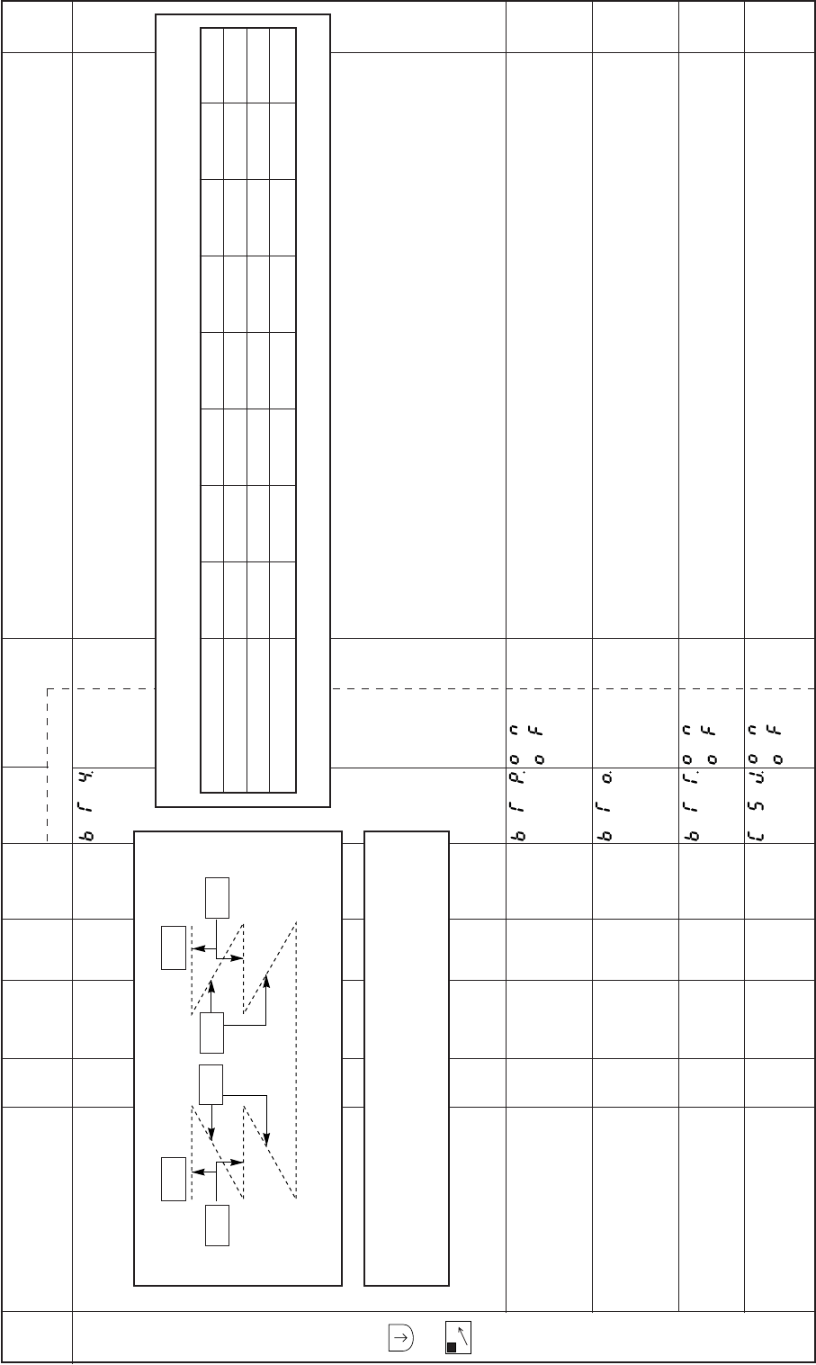
− 95 −
Mode
name Function name Oper
ability
Factory
setting Unit Setting
range Digital display
Function
name Setting Specification Ref.
page
D
mode
+
D
By finely adjusting the backstitch solenoid operation timing of end tacking from forward to reverse,
the no. of stitches can be compensated. The relation of the setting value and no. of stitch compensation
is as shown below.
15 stitches are added to the set No. of start and end tacking stitches.
For example, if the set No. of start tacking stitches is 4 stitches, the actual No. of start tacking stitches
will be 19 stitches (4+15).
[BTO] setting stitches are added to the set No. of start and end tacking stitches.
For example, if the set No. of start tacking stitches is 4 stitches and [BTO] setting value is 20 stitches,
the actual No. of start tacking stitches will be 24 stitches (4+20).
If full heeling is performed immediately after start tacking stops, end tacking will not be performed,
and the sewing machine will stop after thread trimming.
ON The sewing machine temporarily stops immediately before end tacking stitch (Regardless of the
position, the sewing machine stops at DOWN popsition.).
Stop time can be adjusted with the function of stop time CT.
No. of stitch compensation BT4.
for end tacking alignment
No. of tacking stitches (+) BTP.
15 stitches function
No. of tacking stitches BTO.
addition stitches function
Full heeling function BTT.
immediately
after start tacking stop
Temporary stop CSJ.
immediately before
end tacking stitch
O
O
O
O
O
0
OF
0
ON
OF
–
–
–
–
–
0 to F
–
0 to 99
–
–
*
ON
OF
**
ON
OF
ON
OF
BT1 BT2 BT3 BT4
Start End
Caution
If the operation mode during tacking D1 is set to [CST], [CSU] and [CSD],
the tacking alignment functions BM, BT1, BT2, BT3 and BT4 will be
invalid.
Relation of no. of compensated stitches and setting value
Setting value 9 8 7 6 5 4 3 2
No. of compensated –2,1/4 –2 –1,3/4 –1,2/4 –1,1/4 –1 –3/4 –2/4
Setting value 1 0 A B C D E F
No. of compensated –1/4 0 +1/4 +2/4 +3/4 +1 +1,1/4 +1,2/4
–
–
–
–
–
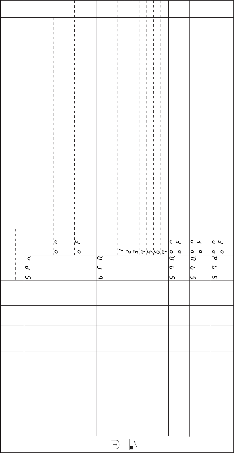
− 96 −
When both the medium speed signal (medium speed run signal S5, medium speed command
signal SPM) and the end tacking speed run signal S5 V is ON, the speed operation mode can be set.
If both the medium speed signal (S5, SPM) and the end tacking speed run signal (S5 V) is ON, the
speed will be the end tacking speed N.
If both the medium speed signal (S5, SPM) and the end tacking speed run signal (S5 V) is ON, the
speed will be the end tacking speed V.
Determine the type of tacking that can be set with the front and end tacking type ([B], [D] keys) in the
tacking setting mode with setting values 1 to 7.
Once tacking (V tacking)
Double tacking (N tacking)
Triple tacking (M tacking)
4 repeat tacking (W tacking)
5 repeat tacking
6 repeat tacking
7 repeat tacking
If the backstitch related inputs are turned ON during preset stitching, the backstitch solenoid will turn
ON.
The backstitch solenoid drive timing by the backstitch signal S7 is synchronized with the UP position.
(When this function setting is [OF] setting, it will be synchronized with the random position.)
The backstitch solenoid drive timing by the backstitch signal S7 is synchronized with the DOWN
position.
(When this function setting is [OF] setting, it will be synchronized with the random position.)
Mode
name Function name Oper
ability
Factory
setting Unit Setting
range Digital display
Function
name Setting Specification Ref.
page
D
mode
+
D
The speed operation SPN.
mode when both
the medium speed
signal and S5 V signal is ON. .
Settable types of tacking BTM.
Input signal S7 operation S7M.
mode during preset
stitching
Manual backstitch S7U.
ON timing 1
Manual backstitch S7D.
ON timing 2
O
O
O
O
O
OF
6
OF
OF
OF
–
–
–
–
–
–
1 to 7
–
–
–
ON
OF
1
2
3
4
5
6
7
ON
OF
ON
OF
ON
OF
–
–
–
–
–
–
–
–
–
–
–
–
–
–

− 97 −
Mode
name Function name Oper
ability
Factory
setting Unit Setting
range Digital display
Function
name Setting Specification Ref.
page
D
mode
+
D
When the manual backstitching signal (S7) is OFF setting, the OFF timing of the backstitching output
B will be synchronized with the UP position.
(When this function setting is [OF] setting, it will be synchronized with the DOWN position.)
The maximum tacking stitches can be set.
The No. of maximum tacking stitches will be 99 stitches.
The No. of start and end tacking stitches will be the same stitches, the No. of start and end tacking
stitches A and D can be set by the 2 figures of [A] and [B] of the operation panel, and the No. of start
and end tacking stitches B and C can be set by the 2 figures of [C] and [D] of the operation panel.
The No. of maximum tacking stitches is 15 stitches.
The No. of end tacking stitches with direct heeling will be the No. of stitches C + 1 stitch when
operation mode D1 is set to [D] [M] during tacking.
The operation mode for when the thread trimmer cancel signal (TL) is input will be set.
The tacking cancel signal [BLT] operation is set.
Tacking is prohibited while the tacking cancel signal [BTL] is ON.
The tacking operation is prohibited once after quick pressing (OFF-ON-OFF) of the tacking cancel
signal [BTL].
The start and end tacking cancel signals SE and EB operations are set.
The start tacking operation is prohibited while the start tacking cancel signal SE is ON. (Same for end
tacking cancel signal EB.)
The start tacking operation is prohibited once after quick pressing (OFF-ON-OFF) of the start tacking
signal SE. (Same for end tacking cancel signal EB.)
The OFF timing setting 7BD.
of output B when the backstitching
signal (S7) is OFF setting.
The maximum BTN.
tacking stitches
(maximum stitches is 99 stitches)
No. of end tacking BCC.
stitches during direct heeling
Operation mode during. TLS.
thread trimmer
cancel signal [TL] setting
Input signal BTL BTS.
quick pressing operation
Input signal SB and EB BS.
quick pressing operation
O
O
O
O
O
O
OF
OF
OF
OF
ON
OF
–
–
–
–
–
–
–
–
–
–
–
–
ON
OF
ON
OF
ON
OF
ON
OF
ON
OF
OF
ON
–
–
–
–
–
–
–
–
–
–
–
–
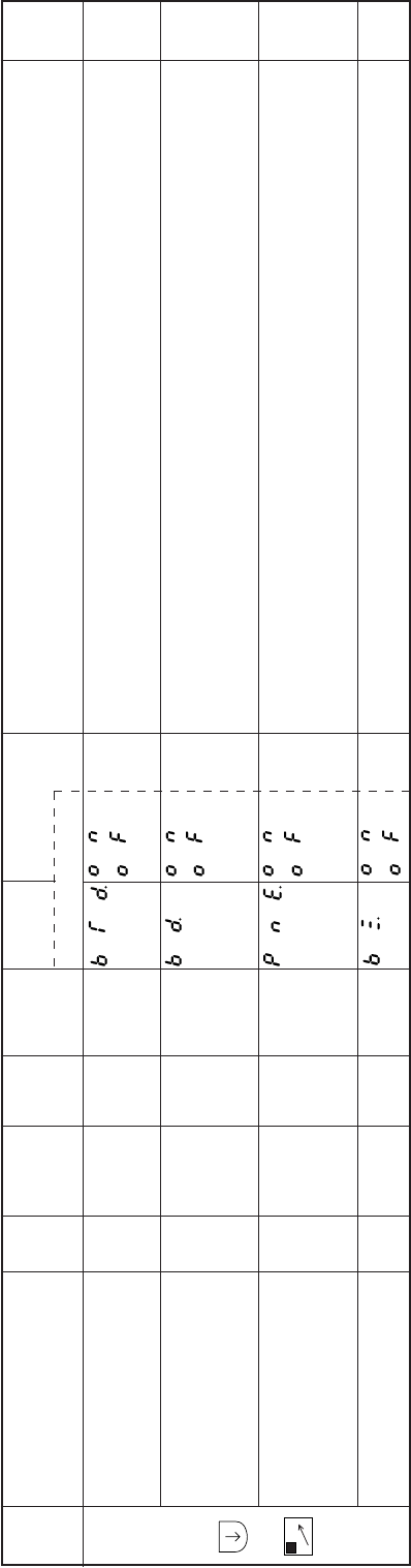
− 98 −
Mode
name Function name Oper
ability
Factory
setting Unit Setting
range Digital display
Function
name Setting Specification Ref.
page
D
mode
+
D
When the tacking is set to OFF, if tacking cancel signal (BTL) turns ON, the tacking will be permitted.
(When this function is set to OFF, the tacking will be prohibited.)
If the start tacking validity ([A] key) is set to OFF (–) in the tacking setting mode, start tacking can be
validated by turning the start tacking cancel signal SE ON. (Same for end tacking cancel signal EB.)
When end tacking is set, if the needle UP position priority stop signal PSU turns ON during operation,
the end tacking will not be executed after stopping at the needle UP position. After thread trimming,
the presser foot will lift.
The buzzer of control panel will be validate.
Operation when input BTD.
signal BTL is ON
Operation when input BD.
signal SB and EB tacking
OFF are set
End tacking PNE.
cancel mode
with input signal PSU
The buzzer of BZ.
control panel validity
O
O
O
O
ON
OF
OF
ON
–
–
–
–
–
–
–
–
ON
OF
ON
OF
ON
OF
ON
OF
–
–
–
–
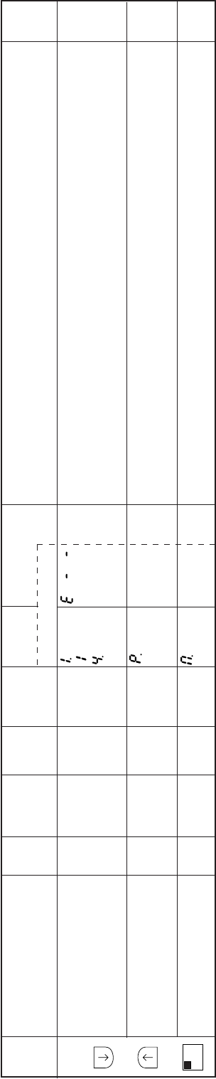
− 99 −
Mode
name Function name Oper
ability
Factory
setting Unit Setting
range Digital display
Function
name Setting Specification Ref.
page
E
mode
+
+
A
1-2
Error codes of once ahead to four times ahead are displayed.
For details of error code, refer to [24. Error Display].
Data can be cleared by simultaneously pressing ([A, 1-2] + [D,==>]) keys.
Total integration time of power on is displayed.
Data can be cleared by simultaneously pressing ([A, 1-2] + [D,==>]) keys.
Total integration time of motor run is displayed.
Data can be cleared by simultaneously pressing ([A, 1-2] + [D,==>]) keys.
Error code didplay 1. to 4.
(Once ahead) to
(Four times ahead)
Total integration time P.
of power on
Total integration time M.
of motor run
O
O
O
E- -
0
0
–
x10
hours
x10
hours
–
0 to 9999
0 to 9999
E- -
****
****
****
****
–
–
–
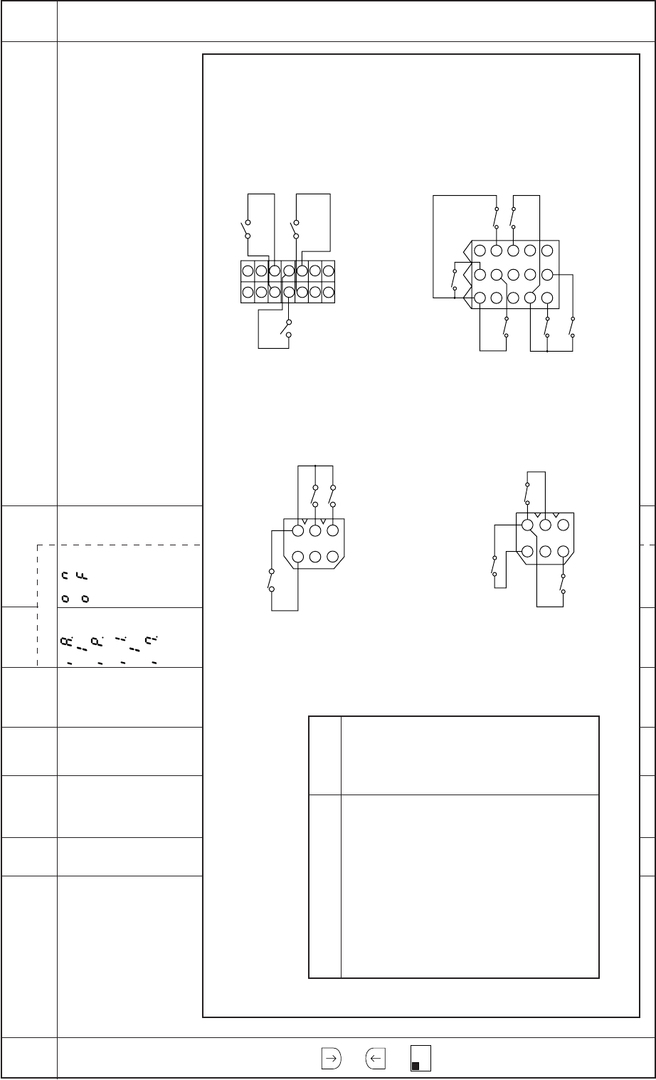
− 100 −
Mode
name Function name Oper
ability
Factory
setting Unit Setting
range Digital display
Function
name Setting Specification Ref.
page
E
mode
+
+
A
1-2
The input status (ON/OFF) of the input signal IA to IP and I1 to I7.Input display IA. to IP.
I1. to I7.
O––– ON
OF
–
Caution
Correspondence of the display and input signal
1
2
3
4
5
6
1
2
3
4
5
6
147
136
125
114
103
92
81
21
54
87
1110
1413
3
6
9
12
15
II
Lever connector
IH
IG
IB
IA
IC
DisplayInput signal
(Factory setting)
Pedal toe down (S1)
Pedal full heeling (S2)
Pedal light heeling (S3)
Presser foot lifter signal (F)
Input signal (TL)
Backstitching signal (S7)
Input signal (PSU)
Input signal (PSD)
Input signal (S0)
Reserved input signal (IO1)
Reserved input signal (U)
Reserved input signal (NO)
Reserved input signal (NO)
Presser foot lifter signal (F)
Reserved input signal (NO)
IG
IH
II
IF
ID
IE
IA
IB
IC
I1
I2
I4
I5
I6
I7 Option A connector
ID
IE
IF
Sewing machine connector
I4
I5
I7
I6
I1
I2
Option B connector
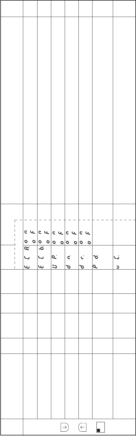
− 101 −
Mode
name Function name Oper
ability
Factory
setting Unit Setting
range Digital display
Function
name Setting Specification Ref.
page
E
mode
+
+
A
1-2
The input status (ON/OFF) of the motor encoder A phase is displayed.
The input status (ON/OFF) of the motor encoder B phase is displayed.
The input status (ON/OFF) of the detector UP signal is displayed.
The input status (ON/OFF) of the detector DN signal is displayed.
Display the angle of current position from down position.
The numerical value that is equivalent to the variable speed voltage VC with the pedal toe down is
displayed. Display range : 000 to 3FF
The numerical value that is equivalent to the variable speed voltage VC with the option B connector
is displayed.
Display range : 000 to 3FF
Encoder signal display ECA.
(A phase)
Encoder signal display ECB.
(B phase)
Detector signal display UP.
(UP signal)
Detector signal display DN.
(DOWN signal)
Display the angle DR.
from down position
Display the voltage of VC1 PD.
Display the voltage of VC2 VC.
O
O
O
O
O
O
O
–
–
–
–
–
–
–
–
–
–
–
x2
Degree
–
–
–
–
–
–
0 to 180
0 to 3FF
0 to 3FF
ON
OF
ON
OF
ON
OF
ON
OF
ON
OF
***
***
***
***
–
–
–
–
–
–
–
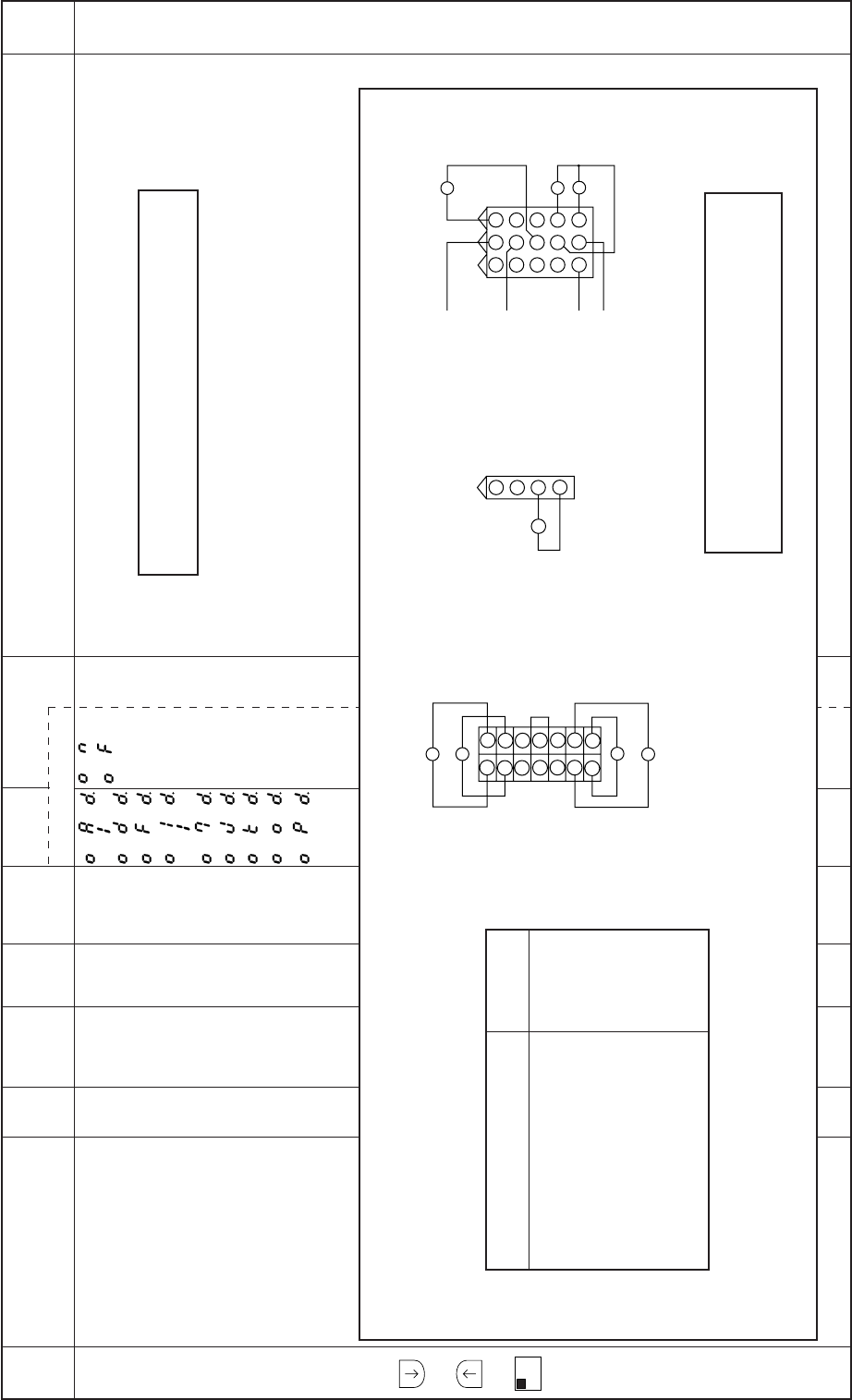
− 102 −
Mode
name Function name Oper
ability
Factory
setting Unit Setting
range Digital display
Function
name Setting Specification Ref.
page
E
mode
+
+
A
1-2
The output status (ON/OFF) of the output signal OA to OD, OF, O1 to O7, OJ, OK, OO, OP.Output signal display
OAD. to ODD.
OFD.
O1D. to O7D.
OJD.
OKD.
OOD.
OPD.
X– – – ON
OF
Note : When CPK is OFF on C mode, the O6D function
is invalidated on E mode.
Caution
Correspondence of the display and output signal
DisplayInput signal
(Factory setting)
Thread trimming output (T)
Wiper output (W)
Backstitch output (B)
Thread release output (L)
Presser foot lifter output (FU)
Virtual output1 (OT1)
Output for needle cooler (NCL)
TF output (TF)
OAD
OBD
OCD
ODD
OFD
O1D
O2D
O3D
3
6
9
2
5
8
1
4
7
121110
151413
O4
O5
O7
O6
O1
O2
O3
714
613
512
411
310
29
18
OB
OA
OD
OC
1
2
3
4
OF
Presser foot lifter connector
Option B connector
Sewing machine connector Caution
Output [O4, O5, O6, O7] are not solenoid output signal.
Also these signal are dual port of input and output.
–
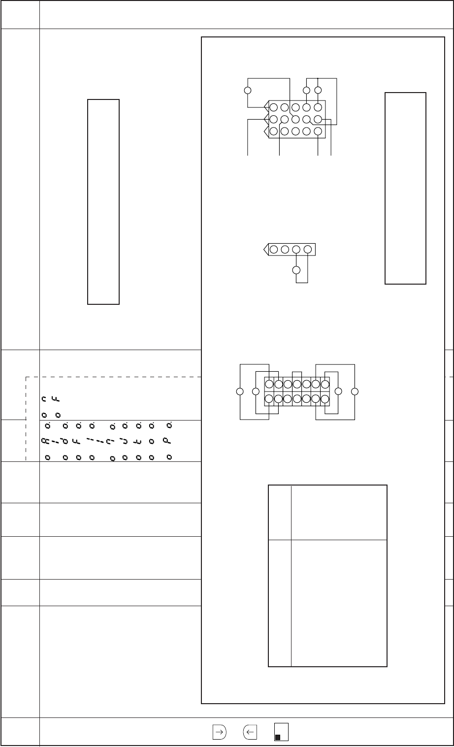
− 103 −
Mode
name Function name Oper
ability
Factory
setting Unit Setting
range Digital display
Function
name Setting Specification Ref.
page
E
mode
+
+
A
1-2
The output status (ON/OFF) of the solenoid output OA to OD, OF, O1 to O7, OJ, OK, OO, OP with
the [D,= =>] key ON/OFF is changed.
Do not turn the O4 to O7 outputs ON/OFF with the [D,= =>] key.
Solenoid output
OAO. to ODO.
OFO.
O1O. to O7O.
OJO.
OKO.
OOO.
OPO.
X– – – ON
OF
Caution
Correspondence of the display and output signal
DisplayInput signal
(Factory setting)
Thread trimming output (T)
Wiper output (W)
Backstitch output (B)
Thread release output (L)
Presser foot lifter output (FU)
Virtual output1 (OT1)
Output for needle cooler (NCL)
TF output (TF)
OAO
OBO
OCO
ODO
OFO
O1O
O2O
O3O
3
6
9
2
5
8
1
4
7
121110
151413
O4
O5
O7
O6
O1
O2
O3
714
613
512
411
310
29
18
OB
OA
OD
OC
1
2
3
4
OF
Presser foot lifter connector
Option B connector
Sewing machine connector Caution
Output [O4, O5, O6, O7] are not solenoid output signal.
Also these signal are dual port of input and output.
Note : When CPK is OFF on C mode, the O6O function
is invalidated on E mode.
–
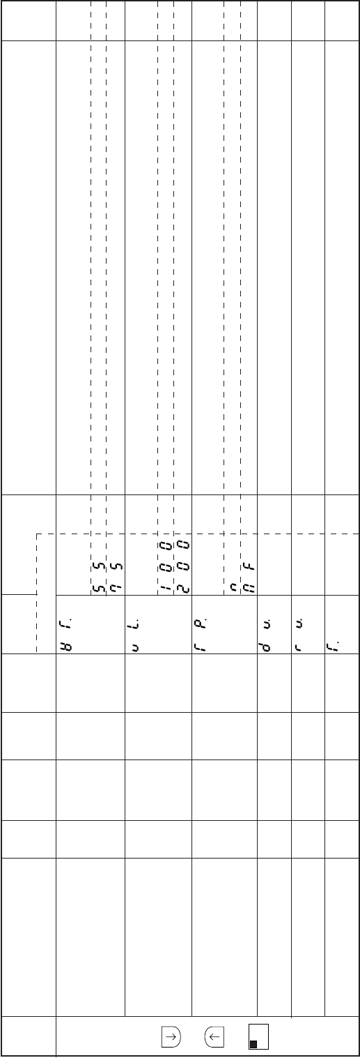
− 104 −
Mode
name Function name Oper
ability
Factory
setting Unit Setting
range Digital display
Function
name Setting Specification Ref.
page
E
mode
+
+
A
1-2
The motor’s rated output value is displayed.
[05] refers to 550 W.
Not used.
The rated input voltage value in the control box is displayed.
[100] refers to 100 V class.
[200] refers to 200 V class.
The control box model name is displayed.
Not used.
SC-380
The data version No. (3-digit alpha-numeral) of the EEPROM is displayed.
The version No. (3-digit alpha-numeral) of the software is displayed.
Display previous simple setting selected.
Rated output display WT.
Voltage display VL.
Model display TP.
Data version No. DV.
Software version No. RV.
Display previous simple T.
setting selected.
O
O
O
O
O
O
55
100
MF
***
***
–
Watt
Volt
–
–
–
–
–
–
–
–
–
–
55
75
100
200
N
MF
***
***
****
***
***
****
–
–
–
–
–
–
–
–
–
–
–
–
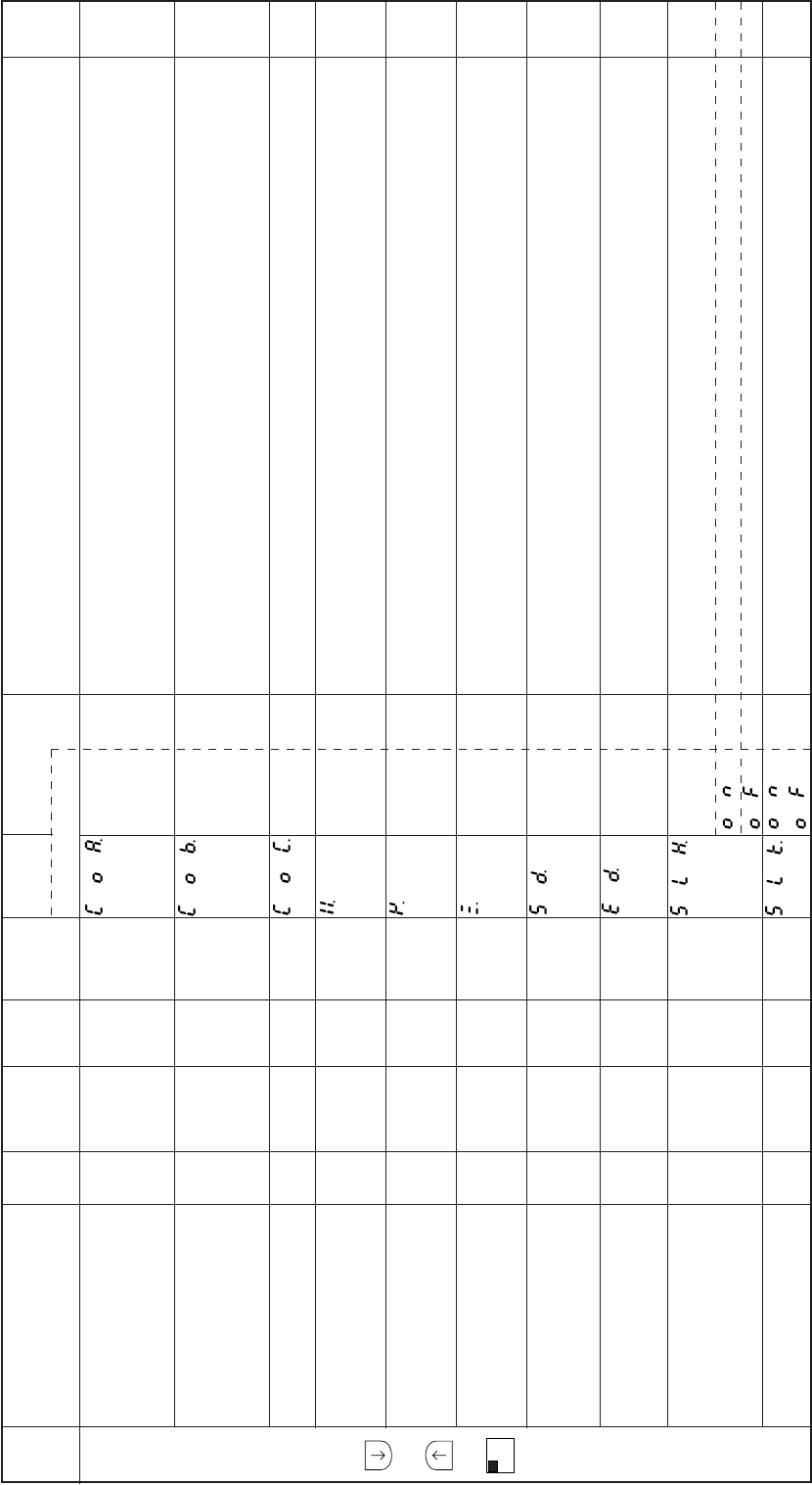
− 105 −
Mode
name Function name Oper
ability
Factory
setting Unit Setting
range Digital display
Function
name Setting Specification Ref.
page
F
mode
+
+
B
SL
The No. of stitches A (delay during chain-off output ON) for chain-off output operation can be set.
When CTR=ON, the No. of stitches for cutter output OFF can be set.
The No. of stitches B (delay during chain-off output OFF) for chain-off output operation can be set.
When CTR=ON, the No. of stitches for cutter output ON can be set.
The No. of stitches C (delay during cutter output ON) during cutter output operation can be set.
The No. of stitches to be stitched before the output BT for the in-tacking signal is turned ON after the
sensor turns OFF can be set.
The No. of stitches to be stitched before the sewing machine stops after the output BT for the in-
tacking signal turns ON can be set.
The No. of stitches to be stitched before the output BT for in-tacking signal is turned OFF after
stitching is started can be set.
The delay time for the output SL to turn from OFF to ON can be set in 2 msec intervals. The cutter
output time setting is also possible.
The delay time for the output SL to turn from ON to OFF can be set in 2 msec intervals. The chain-
off output mesh judgment time setting is also possible.
The No. of set stitches for the output SL can be selected from HOF set No. of stitches (during ON
setting) or SLN set No. of stitches (during OFF setting).
Setting HOF function.
Setting SLN function.
The output of SL for thread dislocation prevention starts when the needle lift operation (US, U, UF) is
completed.
Set No. of stitches COA.
A for cutter output
(Setting the delay
time during chain-off output ON)
Set No. of stitches COB.
B for cutter output
(Setting the delay
time during chain-off output OFF)
Set No. of stitches COC.
C for cutter output
No. of stitches for BT X.
output ON after sensor
OFF setting
No. of stitches for sewing Y.
machine stop after BT
output ON setting
No. of stitches for BT Z.
output OFF after start
of stitching setting
Delay time to when S SD.
output turns from
OFF to ON
Delay time to when SL ED.
output turns from
ON to OFF
No. of set stitches SLH.
during SL output
ON selection mode
SL output start SLK.
position setting
O
O
O
O
O
O
O
O
O
O
0
0
0
0
0
12
0
0
OF
OF
Stitches
Stitches
Stitches
Stitches
Stitches
Stitches
msec
msec
–
–
0 to 99
0 to 99
0 to 99
0 to 99
0 to 99
0 to 99
0 to 508
0 to 508
–
–
**
**
**
**
**
**
***
***
ON
OF
ON
OF
–
–
–
–
–
–
–
–
–
–
–
–
Note) For the details of each function, refer to 19. CUTTER OUTPUT.
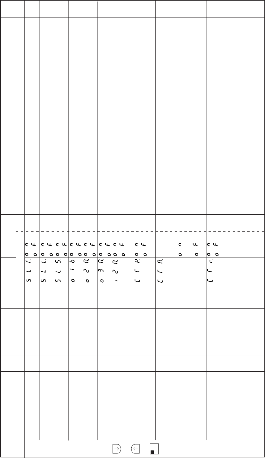
− 106 −
Mode
name Function name Oper
ability
Factory
setting Unit Setting
range Digital display
Function
name Setting Specification Ref.
page
F
mode
+
+
B
SL
When the SL output operation mode SLS is ON while the motor is stopped, the output of SL for
thread dislocation prevention will start after the thread is trimmed.
If the output SL turns ON during an operation other than tacking, the speed is limited to that set in the
medium speed M.
The output SL is ON even when the motor is stopped.
Virtual output OT1 will be set to blower output of cutter function.
Virtual output OT2 can be used as the chain-off output.
Virtual output OT3 can be used as the cutter output.
The mesh judgment control of cutter specification is added to chain-off output.
Refer to the section [21. Input/output function for signal on C mode setting] for details on the IO2, IR2
and IS2 signal function.
When the IO3, IR3 and IS3 signals are ON, the output is set to the manual cutter output. Refer to the
section [21. Input/output function for signal on C mode setting] for details on the IO3, IR3,and IS3
signal function.
The change status of the IO3, IR3 and IS3 signal photo switch that outputs the cutter output by the
virtual output OT3 can be selected. Refer to the section [21. Input/output function for signal on C
mode setting] for details on the IO3 and IR3 and IS3 signal function.
The cutter output by the OT3 is output at both changes (OFF=>ON) (ON=>OFF) of the IO3, IR3 and
IS3 and IS3 signal function.
The cutter output by the OT3 is output at only the (OFF=>ON) change of the IO3, IR3 and IS3 signal
photo switch.
When the IO3, IR3 and IS3 signals are ON, the virtual output OT3 is turned ON/OFF per set No. of
stitches.(When this is turned ON, the cutter specifications by the sensor will be invalidated.)
The set No. of stitches can be set with the cutter specifications No. of stitches A (non-stitching chain
ON delay) setting COA function, cutter specifications No. of stitches B (non-stitching chain ON
delay) setting COB function and the cutter specifications No. of stitches C (non-stitching chain ON
delay) setting COC function.
Refer to the section [21. Input/output function for signal on C mode setting] for details on the IO3,IR3
and IS3 signal function.
SL output start position SLT.
during SLS function ON setting
Speed limit M except SLL.
tacking and SL on
SL output operation SLS.
during motor stop
OT1 output blower O1B.
output setting
OT2 output chain-off O2M.
output setting
OT3 output cutter O3M.
output setting
Mesh judgment I2M.
control with IR2 input
Setting I * 3 signal for CTY.
manual cutter output
Status of cutter output CTM.
photo switch (I*3) signal
according to OT3 output
Turn OT3 output ON/OFF CTR.
per set No. of stitches
when I*3 signal is ON
O
O
O
O
O
O
O
O
O
O
OF
OF
OF
OF
OF
OF
OF
OF
OF
OF
–
–
–
–
–
–
–
–
–
–
–
–
–
–
–
–
–
–
–
–
ON
OF
ON
OF
ON
OF
ON
OF
ON
OF
ON
OF
ON
OF
ON
OF
ON
OF
ON
OF
–
–
–
–
–
–
–
–
–
–
–
–
Note) For the details of each function, refer to 19. CUTTER OUTPUT.

− 107 −
Mode
name Function name Oper
ability
Factory
setting Unit Setting
range Digital display
Function
name Setting Specification Ref.
page
F
mode
+
+
B
SL
The output of the automatic cutter output is prohibited while the sensor is ON.
The output of the automatic cutter output is prohibited while the sensor is OFF.
The output of the automatic cutter output is prohibited when the sensor input is ON while the sewing
machine is stopped.
Automatic stop and trim setting, after the cutter sensor is turned off and then the number of stitch “C”
set by “COC” function is run.
The IO1,IR1 and IS1 signals and the run output OP1 are set to the cutter BT specifications input/
output signals. Refer to the section [21. Input/output function for signal on C mode setting] for details
on the IO3, IR3 and IS3 signal function.
Only the preset No. of stitches is stitched after the operation signal (S1) is turned OFF.
The roller lift output ROL will turn ON when presser foot lifting output FU, backtacking output B,
virtual output OT2 are ON, and during tacking and thread trimming.
The roller lower No. of stitches is set for the auxiliary feeding rear roller.
Automatic cutter CSC.
output prohibit during
sensor ON
Automatic cutter CEC.
output prohibit
during sensor OFF
Cutter output prohibit CTS.
when sensor is ON
while stopped
Automatic thread trim CAT.
setting after cutter sensor
is turned off
Set I*1 input, NOP CTL.
output to cutter BT
specifications input/output
Preset stitching NMD.
operation after operation
signal OFF
ROL output mode RLM.
No. of stitches setting RLN.
for auxiliary feeding
rear roller
O
O
O
O
O
O
O
O
OF
OF
OF
OF
OF
OF
OF
0
–
–
–
–
–
–
–
Stitches
–
–
–
–
–
–
–
0 to 99
ON
OF
ON
OF
ON
OF
ON
OF
ON
OF
ON
OF
ON
OF
****
–
–
–
–
–
–
–
–
Note) For the details of each function, refer to 19. CUTTER OUTPUT.
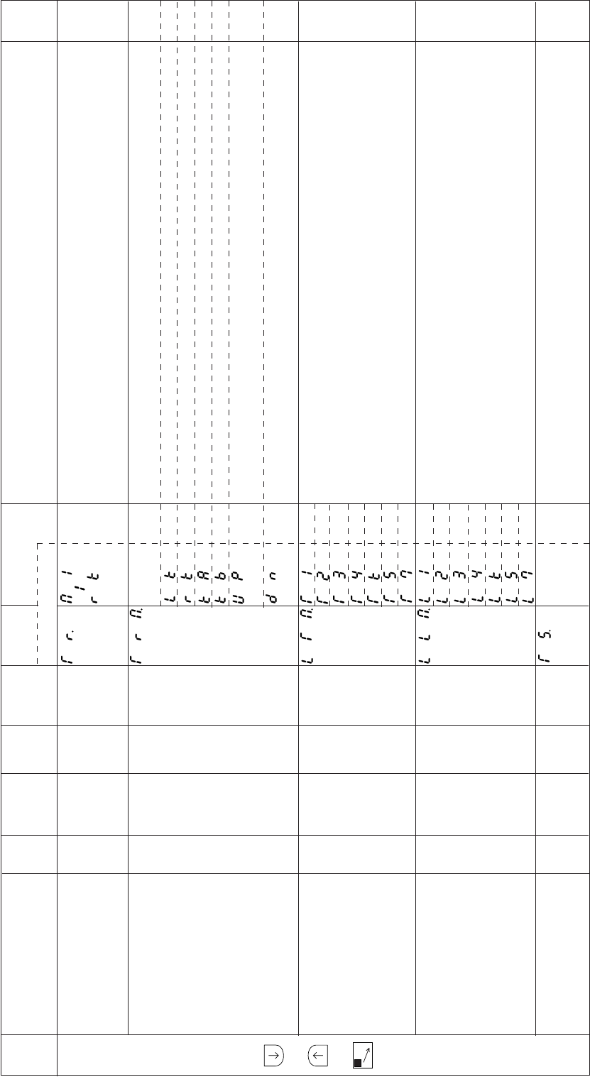
− 108 −
Mode
name Function name Oper
ability
Factory
setting Unit Setting
range Digital display
Function
name Setting Specification Ref.
page
G
mode
+
+
C
The thread trimming timing for each manufacturer’s thread trimming sewing machine can be set.
Same function as the P mode thread trimming mode [TR].
When [PRG] is set, the sewing machine operation and thread trimming timing can be set when
combined with the functions [TRM], [LTM] or [LLM].
The motor operation mode during thread trimming can be set when thread trimming mode TR is set
to [PRG].
The motor will run for the lockstitch thread trimming sewing machine.
The motor will run for reverse thread trimming.
The motor will run (A mode) for the chain stitch thread trimming sewing machine.
The motor will run (B mode) for the chain stitch thread trimming sewing machine.
The motor will run with special functions for the lockstitch thread trimming sewing machine. The
motor stop time TD before thread trimming will be the needle UP position reference.
The motor will run with special functions for the lockstitch thread trimming sewing machine. The
motor stop time TD before thread trimming will be the needle DOWN position reference.
Thread trimming mode TR becomes effective when [PRG] is set.
The output timing mode of the thread trimming output (T) can be selected.
For the details of the selection of the output timing of thread trimming output (T), refer to [12.1) Thread
trimming timing when thread trimming mode TR setting is PRG].
Thread trimming mode TR becomes effective when [PRG] is set.
The output timing mode of the thread release output (L) can be selected.
For the details of the selection of the output timing of thread release output (L), refer to [12.1) Thread
trimming timing when thread trimming mode TR setting is PRG].
When the thread trimming mode TR is set to [PRG], the output start angle of the thread trimming
output (T) can be set.
Set according to the thread trimming output (T) timing chart.
Thread trimming mode TR.
Motor operation TRM.
mode during
thread trimming
Thread trimming LTM.
output (T) output mode
Thread release LLM.
output (L) output mode
Thread trimming TS.
output start angle
O
O
O
O
O
M1
LK
T2
L2
24
–
–
–
–
Degree
M1
to RK
LK
RK
KA
KB
UP
DN
T1
T2
T3
T4
TK
TS
T7
L1
L2
L3
L4
LK
LS
L7
******
–
–
–
–
0 to 360
–
–
–
–
–
–
–
–
–
–
–
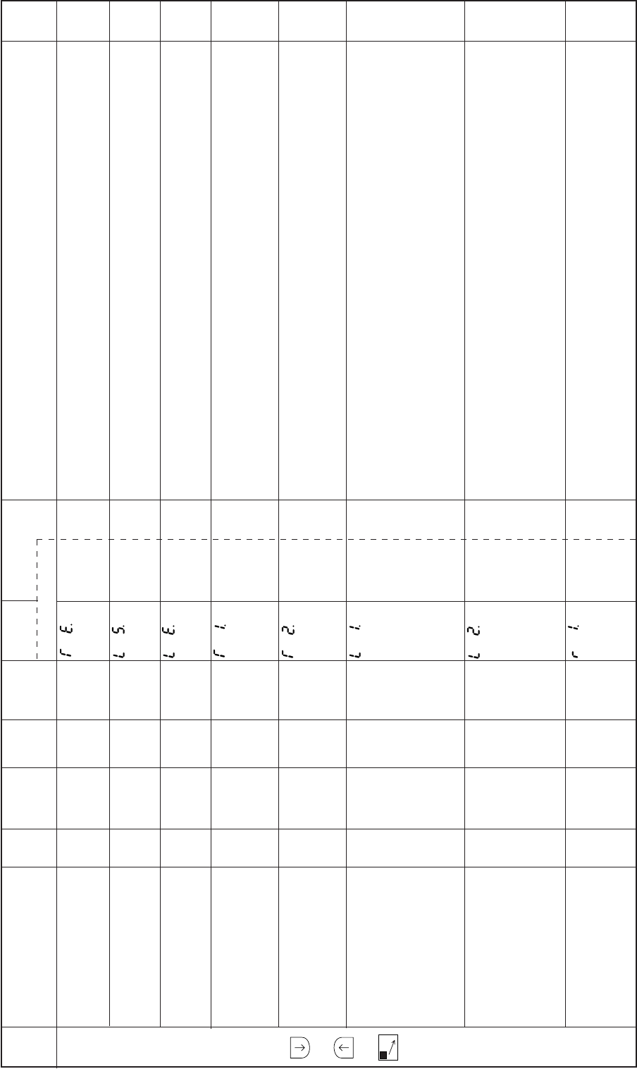
− 109 −
Mode
name Function name Oper
ability
Factory
setting Unit Setting
range Digital display
Function
name Setting Specification Ref.
page
G
mode
+
+
C
When the thread trimming mode TR is set to [PRG], the output end angle of the thread trimming
output (T) can be set.
Set according to the thread trimming output (T) timing chart.
When the thread trimming mode TR is set to [PRG], the output start angle of the thread release
output (L) can be set.
Set according to the thread release output (L) timing chart.
When the thread trimming mode TR is set to [PRG], the output end angle of the thread release
output (L) can be set.
Set according to the thread release output (L) timing chart.
The output start time of the thread trimming output (T) for chain stitch sewing machine can be set.
When the thread trimming mode TR is set to [PRG], the output start time of the thread trimming
output (T) for lock stitch sewing machine can be set. Set according to the thread trimming output (T)
timing chart.
The output time of the thread trimming output (T) for chain stitch sewing machine can be set.
When the thread trimming mode TR is set to [PRG], the output time of the thread trimming output (T)
for lock stitch sewing machine can be set. Set according to the thread trimming output (T) timing
chart.
The output start time of the thread release output (L) for chain stitch sewing machine can be set. The
output start time of the thread release output (L) during chain stitching thread trimming timing A can
be set.
The chain stitching thread trimming timing B is invalid at this time.
When the thread trimming mode TR is set to [PRG], the output start time of the thread release output
(L) for lock stitch sewing machine can be set. Set according to the thread release output (L) timing
chart.
The output time of the thread release output (L) for chain stitch sewing machine can be set. The
output time of the thread release output (L) during chain stitching thread trimming timing A can be
set.
The chain stitching thread trimming timing B is invalid at this time.
When the thread trimming mode TR is set to [PRG], the output time of the thread release output (L)
for lock stitch sewing machine can be set. Set according to the thread release output (L) timing chart.
The output start time of the thread release output (L) during chain stitching thread trimming timing B
can be set. The chain stitching thread trimming timing A is invalid at this time. The output start time
of the output (TF) can be set.
Set according to teach output’s timing chart.
Thread trimming TE.
output angle
Thread release LS.
output start angle
Thread release LE.
output angle
Thread trimming T1.
output start time
Thread trimming T2.
output time
Thread release L1.
output start time
Thread release output time L2.
Thread release outpu R1.
start time
(Output TF start time)
O
O
O
O
O
O
O
O
30
188
134
20
90
150
70
40
Degree
Degree
Degree
msec
msec
msec
msec
msec
0 to 360
0 to 360
0 to 360
0 to 998
0 to 998
0 to 998
0 to 998
0 to 508
***
***
***
***
***
***
***
***
***
***
***
***
***
***
***
***
–
–
–
–
–
–
–
–
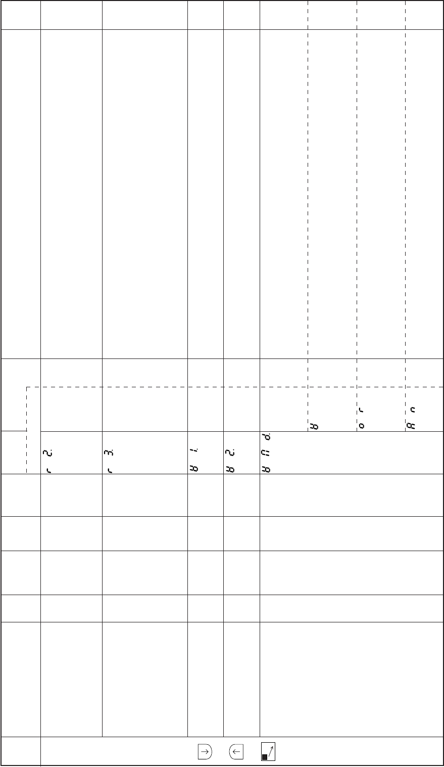
− 110 −
Mode
name Function name Oper
ability
Factory
setting Unit Setting
range Digital display
Function
name Setting Specification Ref.
page
G
mode
+
+
C
The output time of the thread release output (L) during chain stitching thread trimming timing B can
be set. The chain stitching thread trimming timing A is invalid at this time.
The output time of the output (TF) can be set.
Set according to teach output’s timing chart.
The time of when the sewing machine begins condensed stitching after the condensed stitching
(CH) turn ON during start/end condensed stitching can be set.
However, during the end condensed stitching in the chain stitching thread trimming timing B, this
time [R3] will be the time for end condensed stitching after the thread release output (L) turns OFF.
(If end condensed stitching is not set, the time will be that for the needle to rise from the DOWN to UP
position after the thread release output (L) is turned OFF.)
When the thread trimming mode TR is set to [PRG], the output start time of the wiper output (W) can
be set. Set according to the wiper output (W) timing chart.
When the thread trimming mode TR is set to [PRG], the output time of the wiper output (W) can be
set. Set according to the wiper output (W) timing chart.
The output timing mode of the wiper outputÅiWÅjcan be set. The timing that the wiper output W is
turned OFF can be set with the thread trimming signal S2. Refer to [12 . 1)]. Thread trimming timing
when thread trimming mode TR setting is [PRG] for details on setting the OFF timing.
If the S2 signal turns OFF within the wiper output W set time, the W output will turn OFF after the set
time has passed. If the S2 signal turns OFF after the wiper output W set time has passed, the W
output will turn OFF after the set time has passed.
If the S2 signal turns OFF within the wiper output W set time, the W output will turn OFF after the set
time has passed. If the S2 signal turns OFF after the wiper output W set time has passed, the W
output will turn OFF when the S2 signal turns OFF.
If the S2 signal turns OFF without the wiper output W set time, the W output will turn OFF when the
S2 signal turns OFF. If the S2 signal turns OFF after the wiper output W set time passes, the W
output will turn OFF after the set time has passed.
Thread release output R2.
time (TF output time)
Condensed stitching R3.
start time
(Stop time before
thread trimming)
Wiper output start time W1.
Wiper output time W2.
Wiper output WMD.
operation mode
O
O
O
O
O
66
50
10
8
W
0 to 508
0 to 508
0 to 998
0 to 999
–
msec
msec
msec
x10
msec
–
***
***
***
***
W
OR
AN
***
***
***
***
–
–
–
–
–
–
–
–
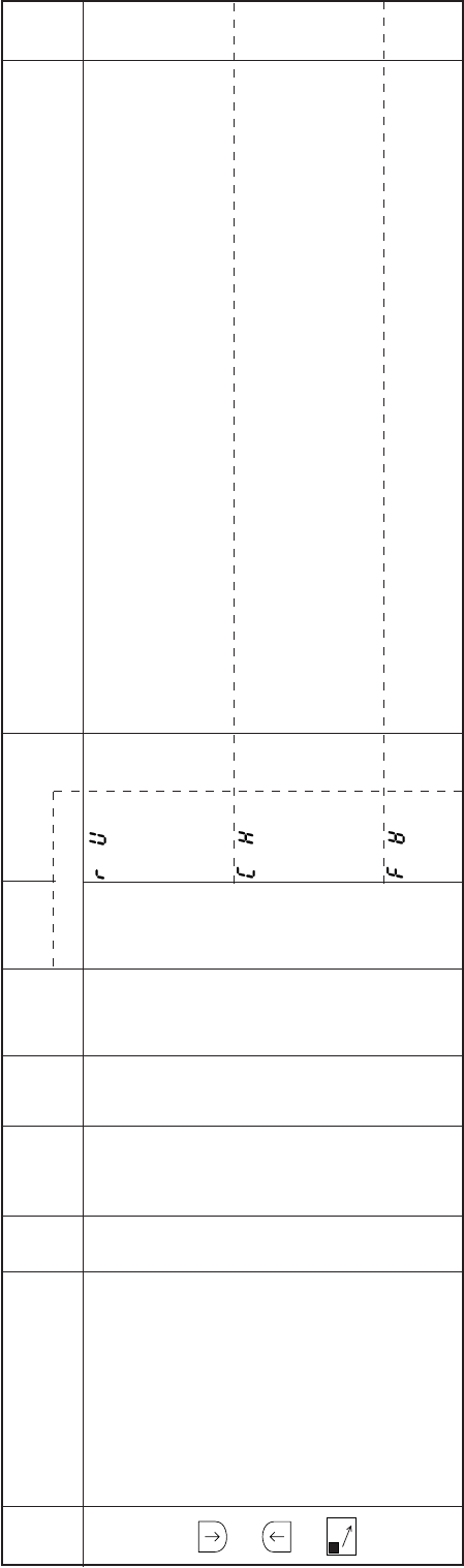
− 111 −
Mode
name Function name Oper
ability
Factory
setting Unit Setting
range Digital display
Function
name Setting Specification Ref.
page
G
mode
+
+
C
This setting is valid when the reverse run needle setting after thread trimming RU is ON. When the
reverse run needle lifting is completed after the thread is trimmed, the W output will turn ON.
If the S2 signal turns OFF within the wiper output W set time, the W output will turn OFF after the set
time has passed. If the S2 signal turns OFF after the wiper output W set time has passed, the W
output will turn OFF after the set time has passed.
This setting is valid when the thread trimming motor operation mode TRM is set to KB. The W output
will start before the short stitch.
If the S2 signal turns OFF within the wiper output W set time, the W output will turn OFF after the set
time has passed. If the S2 signal turns OFF after the wiper output W set time has passed, the W
output will turn OFF after the set time has passed.
This setting is valid when the thread trimming motor operation mode TRM is set to KB. The W output
will start before the sort stitch. The W output will turn OFF when the set time has passed after the
thread trimming operation is completed.
RU
CH
FW
–
–
–
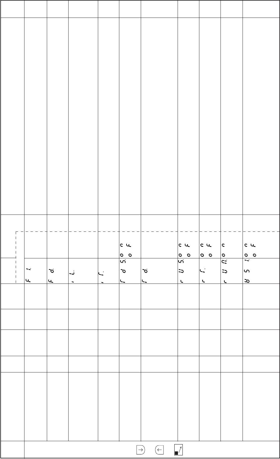
− 112 −
Mode
name Function name Oper
ability
Factory
setting Unit Setting
range Digital display
Function
name Setting Specification Ref.
page
G
mode
+
+
C
When the thread trimming mode TR is set to [PRG], the output start time for the presser foot lifting
output (FU) is set.
Set according to the presser foot lifting output (FU) timing chart.
The time for the motor to start driving after the presser foot output FU is turned OFF when pedal toe
down or external run signal (S0,S1) ON during presser foot lifting can be set in 2 millisecond units.
The interlock time that prohibits operation during thread trimming can be set.
Manual calculation will be used during the [P] mode thread trimming (TR) timing [PRG] ,[KA3], [KA4],
[KB3], [KB4], so the setting is valid.
[KA1], [KA2], [KB1], [KB2] are for automatic calculation and cannot be set.
The interlock time during the no thread trimming timing can be set.This is valid when the [P] mode
thread trimming timing [NO] or thread trimming release signal (TL) is turned ON.
After the motor stops, it will start rotating after the thread trimming output T turns ON and the delay
time has passed. The delay time can be set by the [TD] function.
The motor stop time before thread trimming during lock stitch can be set in 2 msec intervals. The
output R output time during chain stitch can be set in 2 msec.
When the chain stitch mode is set, it is possible to set to the delay time of the motor “R3”. Please refer
to “12 .1) Thread trimming timing when thread trimming mode TR setting is PRG” about the delay
time setting.
Delay time before reverse run (RU operation) after thread trimming is completed can be set with RT
when the thread trimming reverse needle lift RU is set to ON.
When reverse needle lift after thread trimming RU is ON and RUS is ON, the delay time before the
motor reverse run after thread trimming can be set in 2 msec intervals.
Cannot be used.
If the pedal is toed down or external output signal (S2) is turned ON during the wiper output time [W2]
(after thread trimming interlock time),the wiper output time [W] will turn OFF.
The presser foot lifting output (FU) will also turn OFF simultaneously, and the sewing machine will
run after the [FD] time.
Use this for the air type wiper. This is effective for standing operation (automatic machine operation).
Presser foot lifting F1.
output start time
Time to motor drive FD.
after presser foot
lifter bring down
Interlock time IL.
during thread trimming
Interlock time during IT.
no thread trimming
Motor rotation after TDS.
motor stop before
thread trimming
Motor stop time during TD.
lockstitch and R output
time during chain
stitch
Delay setting before RUS.
reverse run during RU
setting
Delay setting before RT.
reverse run during
RU setting
Reverse run needle RUM.
lifting [RU] after output
T,L and W
Wiper output OFF WS1.
trimming with (S1)
signal
O
O
O
O
O
O
O
O
O
O
140
176
140
0
OF
50
OF
76
OF
OF
msec
msec
msec
msec
–
msec
–
msec
–
–
0 to 998
0 to 998
0 to 998
0 to 510
–
0 to 508
–
0 to 508
–
–
***
***
***
***
ON
OF
***
ON
OF
ON
OF
ON
OF
ON
OF
***
***
***
***
***
–
–
–
–
–
–
–
–
–
–
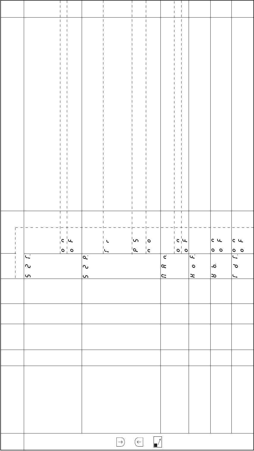
− 113 −
Mode
name Function name Oper
ability
Factory
setting Unit Setting
range Digital display
Function
name Setting Specification Ref.
page
G
mode
+
+
C
If the sewing machine pulley is rotated by hand and set to 1 position while the sewing machine is
stopped before thread trimming, if the needle UP position is 2 position, the needle DOWN position
will shift.
To return to the original stop position after that, fully heel the pedal, or set the operation mode by
turning thread trimming signal (S2) ON.
The same operation as then next [S2P] setting value ([NO], [TR], [PS]) is executed.
The thread trimming operation is executed according to the thread trimming mode TR setting value
([KA1], [KA2], etc.).
The thread mode started with the full pedal heeling or thread trimming signal (S2) ON when rotating
the sewing machine pulley, etc., manually, and leaving the UP position when in 1 position, and
leaving the DOWN position when in 2 position.
When [KA1] to [KA4] of the thread trimming mode [TR] are set, the thread trimming operation will be
performed according to the settings after the needle is lifted.
When [KB1] to [KB4] are set, the thread trimming operation will be performed according to the
settings after the needle is lowered.
The presser foot lifting operation will be executed after the needle is lifted. The thread trimming
operation will not be executed.
The sewing machine does not rotate or perform thread trimming, and only the presser foot lifting
operation is executed.
The sewing of the solenoid output [OT1] manual/automatic output is selected.
The solenoid output [OT1] will be set to manual. The solenoid input signal IO1 is validated.
The solenoid output [OT1] will be set to manual. The solenoid input signal IO1 is validated.
This is valid when the solenoid output [OT1] manual/automatic output change is set to automatic.
If the pedal is toed down or the external run signal (S00, S1, SH) is turned ON while the solenoid
output [OT1] is ON, the OT1 output will turn OFF after the set No. of stitches.
The weak brake will turn ON when the wiper output (W) turns ON.
When the thread trimming output T mode LTM for lockstitch is set to [T1], [T2] or [T3], after the motor
stops, it will start again after the thread trimming output T turns ON and the delay time has passed.
Set time can be set by the [TD] function.
Operation mode with S2T.
thread trimming signal
to shift the needle stop
position and return to
the original needle stop
position before
the thread trimming signal
Operation mode with S2P.
thread trimming signal
when shifting the needle
stop position before
the thread trimming signal
Solenoid output OT1 MAN.
manual/automatic change
Setting of no. of stitches HOF.
during MAN [OFF]setting
Weak brake ON WB.
simultaneously with
wiper output (W)
Motor rotation operation TDT.
when LTM function is set to
T1,T2 or T3
O
O
O
O
O
O
OF
TR
ON
7
OF
OF
–
–
–
Stitches
–
–
–
–
–
0 to 99
–
–
ON
OF
TR
PS
NO
ON
OF
**
ON
OF
ON
OF
**
–
–
–
–
–
–
–
–
–
–
–
–
–
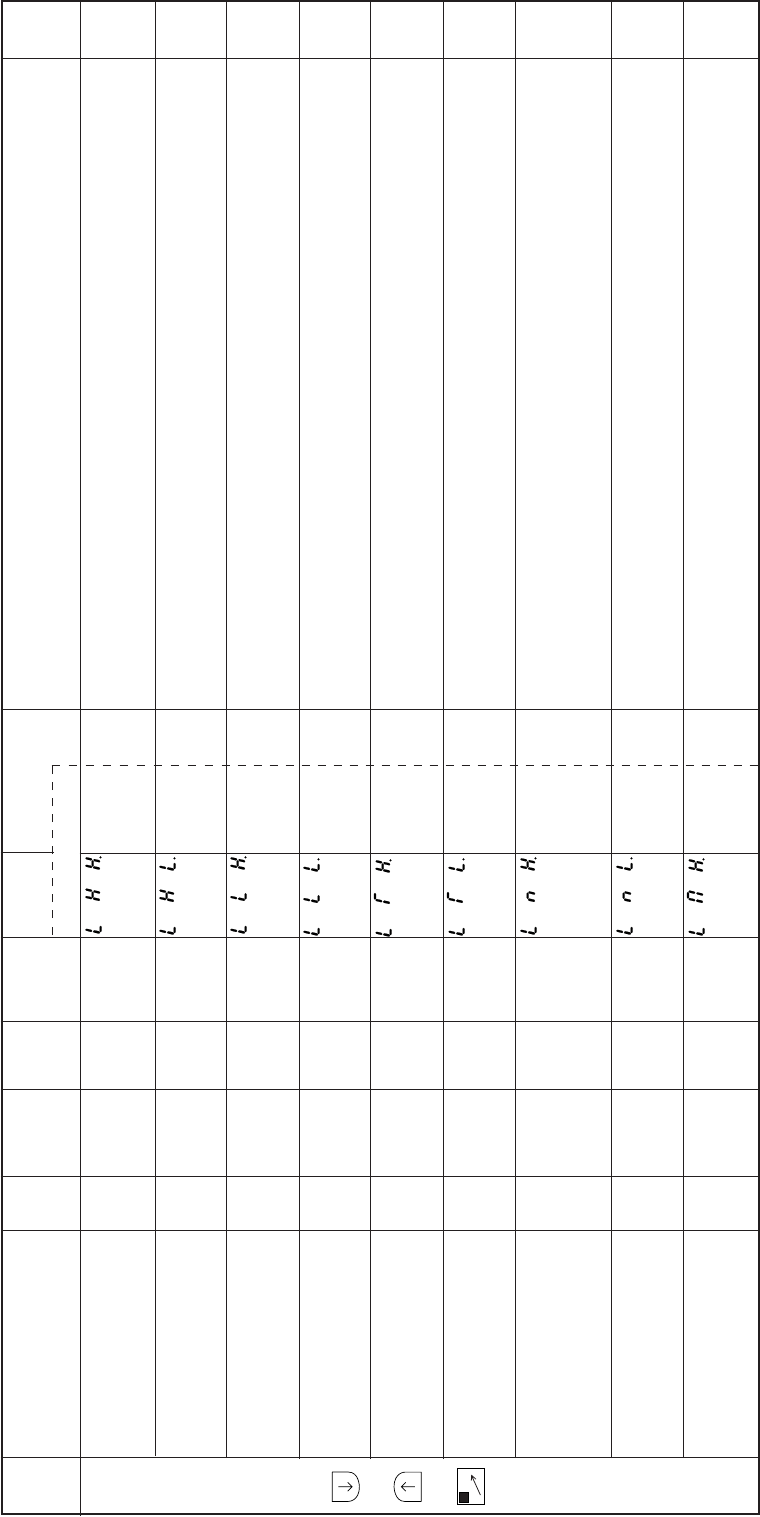
− 114 −
Mode
name Function name Oper
ability
Factory
setting Unit Setting
range Digital display
Function
name Setting Specification Ref.
page
H
mode
+
+
D
The upper limit value of the maximum speed [H] in P mode is set.
A value that exceeds the value set in this limiter cannot be set for the maximum speed [H].
The factory setting [90] refers to [90x100=9000] r/min.
The lower limit value of the maximum speed [H] in P mode is set.
A value that is lower than the value set in this limiter cannot be set for the maximum speed [H].
The upper limit value of the maximum speed [L] in P mode is set.
A value that exceeds the value set in this limiter cannot be set for the low speed [L].
The factory setting [5] refers to [5x100=500] r/min.
The lower limit value of the low speed [L] in P mode is set.
A value that is lower than the value set in this limiter cannot be set for the low speed [L].
The upper limit value of the thread trimming speed [T] in P mode is set.
A value that exceeds the value set in this limiter cannot be set for the thread trimming speed [T].
The factory setting [5] refers to[5x100=500] r/min.
The lower limit value of the thread trimming speed [T] in P mode is set.
A value that is lower than the value set this limiter cannot be set for the thread trimming speed [T].
The upper limit value of the start/end tacking (condensed stitching) speed in P mode is set.
A value that exceeds the value set in this limiter cannot be set for the start/end tacking (condensed
stitching) speed.
The factory setting [30] refers to [30x100=3000] r/min.
The lower limit value of the start/end tacking (condensed stitching) speed in P mode is set.
A value that is lower than the value set in this limiter cannot be set for the start/end tacking (condensed
stitching) speed.
The upper limit value of the medium speed [M] in P mode is set.
A value that exceeds the value set in this limiter cannot be set for the medium speed [M].
The factory setting [90] refers to [90x100=9000] r/min.
Upper limit of LHH.
maximum speed [H]
Lower limit of LHL.
maximum speed [H]
Upper limit of LLH.
low speed [L]
Lower limit of LLL.
low speed [L]
Upper limit of LTH.
thread trimming
speed [T]
Lower limit of LTL.
thread trimming
speed [T]
Upper limit of LNH.
start/end tacking
(condensed stitching)
speed
Lower limit of LNL.
start/end tacking
(condensed stitching) speed
Upper limit of LMH.
medium speed [M]
O
O
O
O
O
O
O
O
O
90
0
5
0
5
0
30
0
90
x100
r/min
x100
r/min
x100
r/min
x100
r/min
x100
r/min
x100
r/min
x100
r/min
x100
r/min
x100
r/min
0 to 99
0 to 99
0 to 99
0 to 99
0 to 99
0 to 99
0 to 99
0 to 99
0 to 99
**
**
**
**
**
**
**
**
**
**
**
**
**
**
**
**
**
**
–
–
–
–
–
–
–
–
–
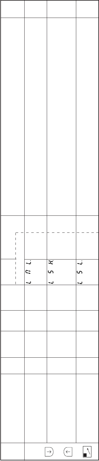
− 115 −
Mode
name Function name Oper
ability
Factory
setting Unit Setting
range Digital display
Function
name Setting Specification Ref.
page
H
mode
+
+
D
The lower limit value of the medium speed [M] in P mode is set.
A value that is lower than the value set in this limiter cannot be set for the medium speed [M].
The upper limit value of the medium speed [M] in P mode is set.
A value that exceedsthe value set in this limiter cannot be set for the medium speed [M].
The factory setting [30] refers to [30x100=3000] r/min.
The lower limit value of the medium speed [S] in P mode is set.
A value that is lower than the value set in this limiter cannot be set for the medium speed [S].
Lower limit of LML.
medium speed [M]
Upper limit of LSH.
slow start speed [S]
Lower limit of LSL.
slow start speed [S]
O
O
O
0
30
0
x100
r/min
x100
r/min
x100
r/min
0 to 99
0 to 99
0 to 99
**
**
**
**
**
**
–
–
–

− 116 −
Mode
name Function name Oper
ability
Factory
setting Unit Setting
range Digital display
Function
name Setting Specification Ref.
page
J
mode
+
+
A
1-2
+
B
SL
The simple setting mode (program mode [1] for Mitsubishi thread trimming sewing machine) cannot
be entered.
([ ↓]+[A]+[B] key operation will not be possible.)
The [P] mode thread trimmer mode, TR cannot be entered.([ ↓]+[ ↑] key operation (program
mode P) will be possible.) The thread trimmer mode [G] cannot be entered.
([ ↓]+[ ↑]+[C] key operation will not be possible.)
Rotation direction changeover ([↓]+[M] key operationÅjduring the normal mode will not be possible.
1-2 position changeover ([A] key operation) during the normal mode will not be possible.
Slow start validity changeover ([B] key operation) during the normal mode will not be possible.
Speed setting operation of normal mode ([C] key and [D] key operation) jwill not be possible.
Not used.
Start tacking validity changeover ([A] key operation) during the tacking mode will not be possible.
The No. of start tacking stitches setting ([A], [B] key operations) during the tacking mode will not be
possible.
End tacking validity changeover ([C] key operation) during the tacking mode will not be possible.
The No. of end tacking validity changeover ([C], [D] key operations) during the tacking mode will not
be possible.
Start tacking type setting ([B] key operation) during the tacking mode will not be possible.
End tacking type setting ([D] key operation) during the tacking mode will not be possible.
Simple setting mode for MAC.
Mitsubishi thread trimming
sewing machine prohibit
[P], [G] mode thread TRC.
trimmer mode TR prohibit
Rotation direction CWC.
changeover prohibit
1-2 position changeover 12C
prohibit
Slow start changeover SLC.
prohibit
Speed setting key SPC.
changeover prohibit
JKC.
Start tacking validity SBC.
changeover prohibit
No. of start tacking SNC.
stitches changeover
prohibit
End tacking validity EBC.
changeover prohibit
No. of end tacking ENC.
stitches changeover prohibit
Start tacking type SKC.
changeover prohibit
End tacking type EKC.
changeover prohibit
O
O
O
O
O
O
O
O
O
O
O
O
O
ON
OF
ON
OF
OF
OF
OF
OF
OF
OF
OF
OF
OF
–
–
–
–
–
–
–
–
–
–
–
–
–
ON
OF
ON
OF
ON
OF
ON
OF
ON
OF
ON
OF
ON
OF
ON
OF
ON
OF
ON
OF
ON
OF
ON
OF
ON
OF
–
–
–
–
–
–
–
–
–
–
–
–
–
–
–
–
–
–
–
–
–
–
–
–
–
–
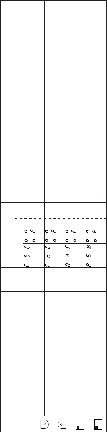
− 117 −
Mode
name Function name Oper
ability
Factory
setting Unit Setting
range Digital display
Function
name Setting Specification Ref.
page
J
mode
+
+
A
1-2
+
B
SL
Preset stitching validity and backtacking validity changeover operation ([M] key operation) in the
pattern mode will not be possible.
No of preset stitching stitches and No. of backtacking times setting operation ([C], [D] key operations)
in the pattern mode will not be possible.
Preset stitching, backtacking and control switch panel data play mode changeover ([D] key operation)
in the pattern mode will not be possible.
Panel switch operation ([M], [A], [B], [C], [D] key operations) during the normal mode, tacking mode
and pattern mode will not be possible.
However, changeover into each mode will be possible.
Pattern stitching TSC.
validity changeover prohibit
Pattern stitching No. TNC.
of stitches and times
changeover prohibit
Pattern mode pattern MDC.
changeover prohibit
Panel switch PSW.
operation prohibit
O
O
O
O
OF
OF
OF
OF
–
–
–
–
–
–
–
–
ON
OF
ON
OF
ON
OF
ON
OF
–
–
–
–
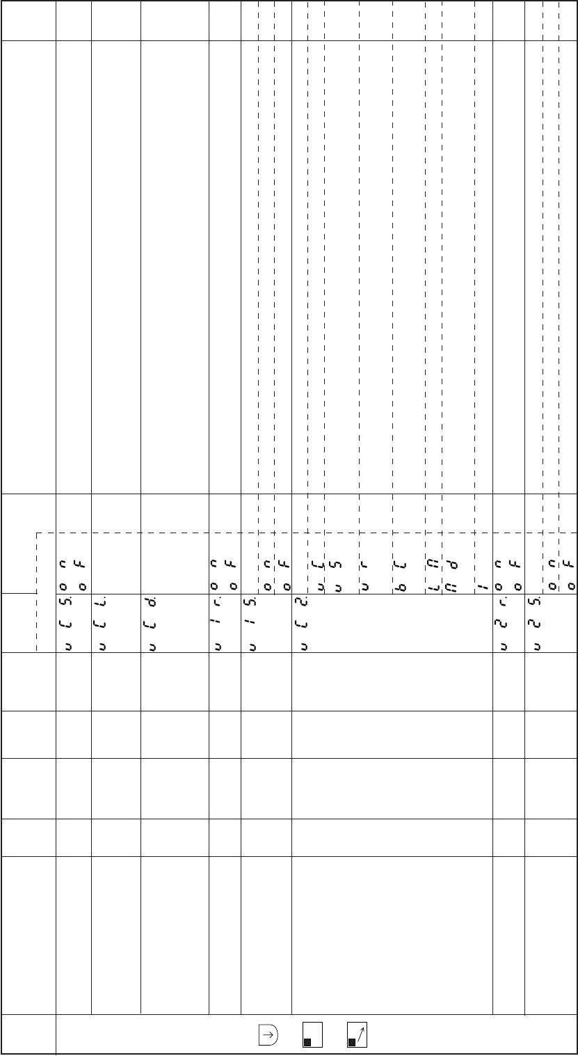
− 118 −
Mode
name Function name Oper
ability
Factory
setting Unit Setting
range Digital display
Function
name Setting Specification Ref.
page
Q
mode
+
A
1-2
+
C
The virtual operation signal S1 is turned ON when the variable speed voltage VC1 and VC2 exceeded
the set voltage level.
The voltage level of the variable speed voltage VC1 and VC2 where virtual run signal S1 turns ON.
The voltage level hysteresis width for judging the ON/OFF of the virtual S1 signal when VCS turns
ON can be set.
The voltage curve of the variable speed voltage VC1 is reversed.
The VC1 input range is set to 0 to 5 V.
VC1 maximum input voltage is set to 5 V.
VC1 maximum input voltage is set to 12 V.
The external analog input VC2 function is set.
Speed command input
The virtual S1 signal turns on with the input voltage, and the sewing machine runs. This also acts as
the speed command input.
The VC2 input acts as the variable resistor on the control box panel, and the variable resistor is
invalidated.
During operation with the BC and BCR input, the speed set with the program P mode C8 is invalidated,
and the speed is controlled with the VC2 input.
The speed control input for reciprocal stroke change.
The value set in the program P mode M is invalidated, and the middle speed is controlled with the
VC2 input voltage.
Virtual input IO1 is selected.
The external analog input VC2 curve is reversed.
The VC2 input rang is set to 0 to 5 V.
VC2 maximum input voltage is set to 5 V.
VC2 maximum input voltage is set to 12 V.
Virtual S1 operation VCS.
with VC1 levels
Setting of VC1 and VC2 VCL.
where virtual
S1 turns ON
Input voltage hysteresis VCD.
during virtual S1 signal
ON/OFF by VC1 and VC2 level
VC1 curve V1R.
reversal mode
VC1 input 5 V/12 V V15.
changeover mode
VC2 operation mode VC2.
VC2 curve V2R.
reversal mode
VC2 input 5 V/12 V V25.
changeover mode
×
×
×
×
×
×
×
×
OF
24
4
OF
OF
LM
OF
OF
–
–
–
–
–
–
–
–
–
1 to 99
0 to 99
–
–
–
–
–
ON
OF
**
**
ON
OF
ON
OF
VC
VS
VR
BC
LM
MD
1
ON
OF
ON
OF
**
**
–
–
–
–
–
–
–
–
–
–
–
–
–
–
–
–
–
–
–
–
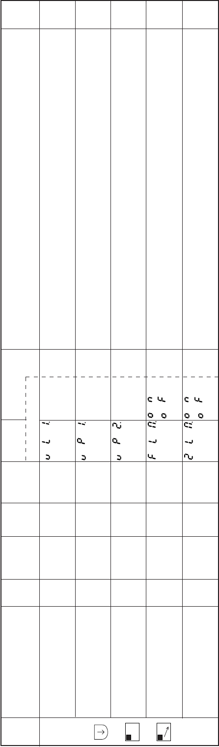
− 119 −
Mode
name Function name Oper
ability
Factory
setting Unit Setting
range Digital display
Function
name Setting Specification Ref.
page
Q
mode
+
A
1-2
+
C
The inflection point is set when using the reciprocal stroke change specification speed limiter process
(VC2=LM.)
Setting inflection point 1
Setting inflection point 2
The speed limit is valid only if the presser foot is rising when the VC2 operation mode is set to LM or
the medium speed limit function LIM. Is set to ON during OT1 output ON.
The speed limit is valid only if the virtual output OT2 is ON when the VC2 operation mode is set to LM
or the medium speed limit function LIM. Is set to ON during OT1 output ON.
Speed limiter curve VL1.
inflection point 1 percentage
Speed limiter curve VP1.
inflection point 1 point
Speed limiter curve VP2.
inflection point 2 point
Operation speed limit FLM.
specification mode 1
Operation speed limit 2LM.
specification mode 2
O
O
O
O
O
56
39
42
OF
OF
%
–
–
–
–
1 to 99
1 to 99
1 to 99
–
–
**
**
**
ON
OF
ON
OF
**
**
**
–
–
–
–
–
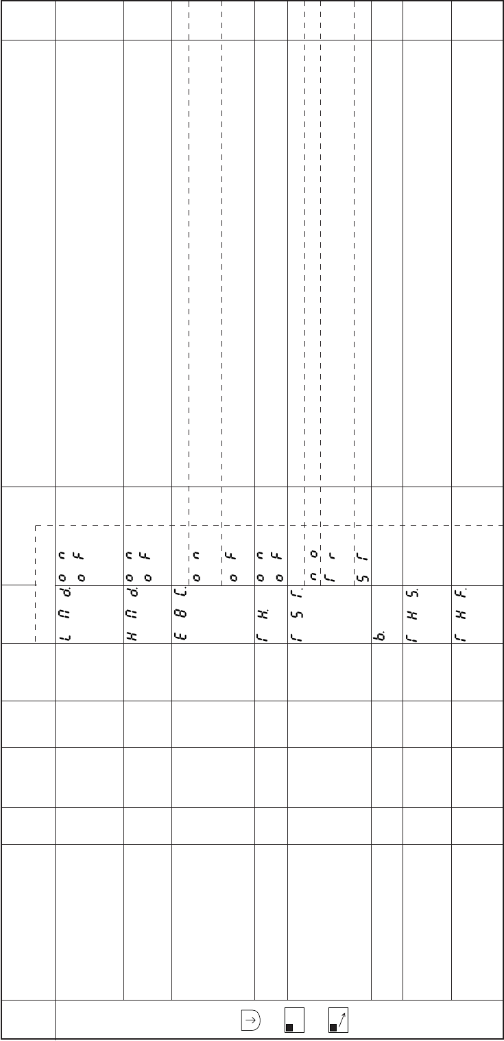
− 120 −
Mode
name Function name Oper
ability
Factory
setting Unit Setting
range Digital display
Function
name Setting Specification Ref.
page
Q
mode
+
A
1-2
+
C
The middle speed during the speed limit process is read into the speed command value (speed high
speed signal SPH, speed end tacking signal SPB, speed medium speed signal SPM, high speed
run signal S4, end tacking speed run signal S5 V, medium speed run signal S5) other than the low
speed from an external source by the digit.
The speed during stitching other than tacking is limited by the digital speed setting (LED C and D) on
operation panel.
The sewing machine detector error E8 will be ignored.
If a signal is not received from the sewing machine detector within a set time during operation, the
detector error E8 will not be displayed.
If a signal is not received from the sewing machine detector within a set time during operation, the
detector error E8 will be displayed and the sewing machine will stop.
The thread break detector is validated.
The operation after the thread break is detected (thread break sensor detection) is set.
The operation continues, and the thread break sensor output THO turns ON.
The sewing machine stops after the thread trimming, and then the thread break sensor output THO
turns ON.
The sewing machine stops normally, and then the thread break sensor output THO turns ON.
The speed to ignore the thread break sensor can be set.
Setting the number of stitch that the sensor of thread break detector becomes valid from first stitch.
The No. of stitches to judge the thread break detection when the thread break sensor input continues
for a certain number of stitches can be set.
Speed command value LMD.
correctly by middle speed
digital during speed
limit process.
Speed limit with digital HMD.
speed setting on
operation panel
Ignore detector error E8C.
Thread break sensor valid TH.
Operation after thread TST.
break sensor detection
Speed to ignore B.
thread break sensor
No. of stitches to THS.
ignore thread break
sensor after starting stitching
Number of stitches THF.
for judgment of
thread break.
O
O
O
O
O
O
O
O
–
–
–
–
–
r/min
Stitches
Stitches
OF
OF
OF
OF
TR
600
7
0
–
–
–
–
–
0 to 8999
0 to F
0 to F
ON
OF
ON
OF
ON
OF
ON
OF
NO
TR
ST
****
**
**
****
**
**
–
–
–
–
–
–
–
–
–
–
–
–
–
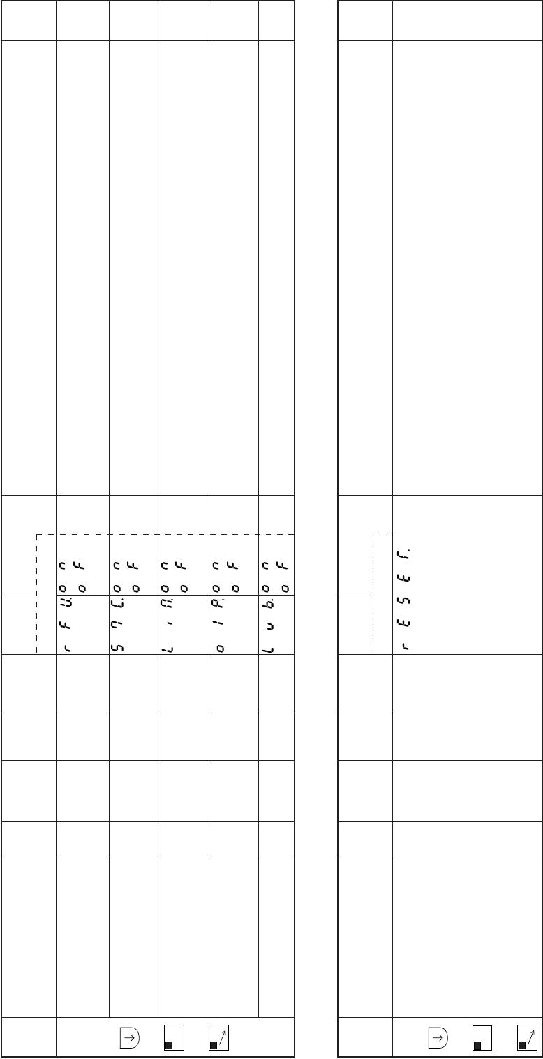
− 121 −
The presser foot lifting output will turn ON by turning ON the presser foot lifting signal F during sewing
machine operation.
Note that the presser foot lifting signal S3 is invalid during sewing machine operation.
The output of the backstitching output (B) with input S7 is inhibited while the virtual output (OT1) is
ON.
The speed will be limited to that set in medium speed M while virtual output (OT1) is ON.
OP1 output will turn ON simultaneously when virtual output (OT1) is ON.
When the lever unit run signal S1 is ON, the presser foot lift signal S3 will be ignored even when
received.
Mode
name Function name Oper
ability
Factory
setting Unit Setting
range Digital display
Function
name Setting Specification Ref.
page
Q
mode
+
A
1-2
+
C
Operation mode with RFU.
F input during sewing
machine operation
Output of backtacking S7C.
output (B) during OT1
output ON inhibited
Medium speed (M) LIM.
limit mode during OT1
output ON
Simultaneously ON of O1P.
OP1 output during
OT1 output ON
Disregard of S3 LVB.
signal of Lever Unit
O
O
O
O
O
OF
OF
ON
OF
ON
–
–
–
–
–
–
–
–
–
–
ON
OF
ON
OF
ON
OF
ON
OF
ON
OF
–
–
–
–
–
EEPROM data is returned to EEPROM back-up state.
This function can be used when returning the function setting to the factory setting.
Every time [D,==>] key is pressed for two seconds or more, the mode returns to the normal mode
after copying (factory setting data) to (existing data).
Mode
name Function name Oper
ability
Factory
setting Unit Setting
range Digital display
Function
name Setting Specification Ref.
page
R
mode
+
B
SL
+
C
Reset RESET x – – – –
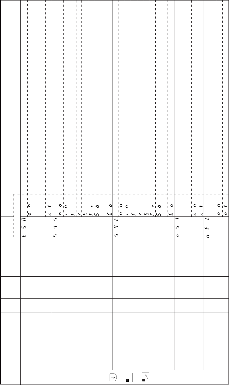
− 122 −
Mode
name Function name Oper
ability
Factory
setting Unit Setting
range Digital display
Function
name Setting Specification Ref.
page
S
mode
+
B
SL
+
D
This is the virtual output KS1 and KS2 run mode.
During the one needle stitching, half-stitching (one needle stitching signal S01, needle lift signal U,
half-stitching signal UD, backstitching during run signal US, backstitching during run signal
UDS,etc.),The outputs KS1 and KS2 will turn ON.
The KS1 and KS2 output swill turn ON only during normal operation.
The simple sequence start conditions are set.
The simple sequence will not start.
When the input signal I4 (IN4) is ON.
When the thread trimming is completed.
When run starts.
When the motor starts. (This includes while stopped during the one needle stitching run.)
When stitching starts after thread trimming.
When start tacking is completed. (If the start tacking setting is OFF, the operation will be identical to
[TR].)
Normal starting.
The simple sequence end conditions are set.
The simple sequence is not compulsorily ended.
When the input signal (15) is ON.
When the thread trimming is completed.
When run starts.
When the motor stops. (This includes while stopped during the one needle stitching run.)
When stitching starts after thread trimming.
When start tacking is completed. (When the start tacking setting is [OF], the operation will be identical
to [TR] setting.
The use is prohibited.
[Time] / [No. of Stitches] selection for start of KS1 output. The [Time] / No. of Stitches] can be set with
the KS1 output start [Time] / [No. of Stitches] setting K11.
The KS1 output start time can be set with a No. of stitches.
The KS1 output start time can be set as a time. (10 msec unit)
This is the simple sequence output KS1 output time/output No. of stitches setting changeover function.
The [Time] / [No. of Stitches] can be set with the KS1 output [Time] / [No. of Stitches] setting K12.
The KS1 output time can be set with a No. of stitches.
The KS1 output time can be set as a time. (10 msec unit)
KS1,KS2 output run KSM.
mode
Simple sequence SQS.
start conditions
When the motor stops SQE .
(This includes while
stopped during the one
needle stitching run.)
Simple seuence
end conditions
This is the simple NS1.
sequence output KS1
output start time/output
start No. of stitches
setting changeover function.
[Time]/[No. of Stitches] NE1.
selection for KS1 output
O
O
O
O
O
OF
NO
NO
OF
OF
–
–
–
–
–
–
–
–
–
–
ON
OF
NO
IN
T
R
S
TR
SB
GO
NO
IN
T
R
S
TR
SB
GO
ON
OF
ON
OF
–
–
–
–
–
–
–
–
–
–
–
–
–
–
–
–
–
–
–
–
–
–
–
–
–
–
–
Note) For the details of each function, refer to 15. SIMPLE SEQUENCE.
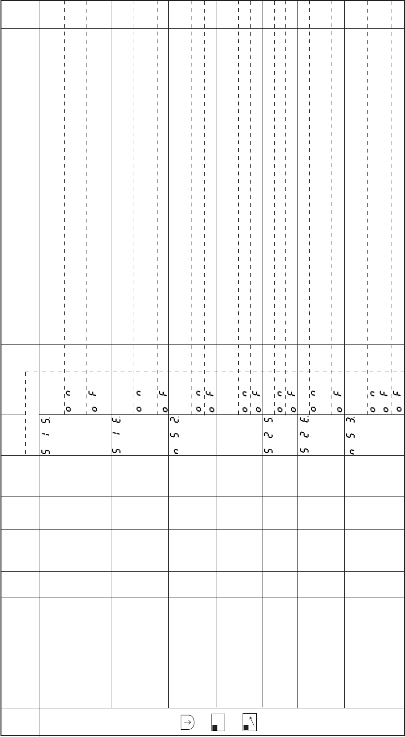
− 123 −
Mode
name Function name Oper
ability
Factory
setting Unit Setting
range Digital display
Function
name Setting Specification Ref.
page
S
mode
+
B
SL
+
D
The simple sequence output KS1 output start reference is set. The setting time can be set with the
KS1 output start [Time]/[No. of stitches] setting K11.
Using the input signal 12 ON as a reference after the start conditions are established, the KS1 output
will turn ON after the set time has passed.
Using the start conditions establishment as a reference, the KS1 output will turn ON after the set time
has passed.
The simple sequence output KS1 output end reference is set. The setting time can be set with the
KS1 output [Time]/[No. of Stitches] setting K12.
Using the input signal 12 OFF as a reference after the KS1 output turns ON, the KS1 output will turn
OFF after the set time has passed.
Using the KS1 output ON as a reference, the KS1 output will turn OFF after the set time has passed.
Selection stitch amount and time till ON for simple sequence output “KS2” (Amount have to be set at
“K21”)
Stitch amount is counted till ON
Time is counted till ON (10 mill-second per each)
Selection stitch amount and time till OFF for simple sequence output “KS2” (Amount have to be set
at “K22”)
Stitch amount is counted till OFF.
Time is counted till OFF (10 mill-second pre each)
Setting start condition of counting till ON for simple sequence output “KS2”.
When Input signal “I7” become ON after the count start condition was established, counting will start.
When the count start condition is established, counting will start.
Setting start condition of counting till ON for simple sequence output “KS2”.
When Input signal “I7” become OFF after the count start condition was established, counting will
start.
When the count start condition is established, counting will start.
Selection stitch amount and time till ON for simple sequence output “KS3” (Amount have to be set at
“K21”)
Stitch amount is counted till ON.
Time is counted till ON (10 mill-second per each)
When the count start condition is established, counting will start.
KS1 output start S1S.
reference setting.
KS1 output end S1E.
reference setting.
KS2 : Selection of NS2.
Stitch amount and time till ON
KS2 : Selection of NE2.
Stitch amount and time till OFF
KS2 : Setting of count S2S.
condition till ON
KS2 : Setting of count S2E.
condition till OFF
KS3 : Selection of Stitch NS3.
amount and time till ON
O
O
O
O
O
O
O
OF
OF
OF
OF
OF
OF
OF
–
–
–
–
–
–
–
ON
OF
ON
OF
ON
OF
ON
OF
ON
OF
ON
OF
ON
OF
OF
–
–
–
–
–
–
–
–
–
–
–
–
–
–
–
–
–
–
–
–
–
–
–
–
–
–
–
Note) For the details of each function, refer to 15. SIMPLE SEQUENCE.
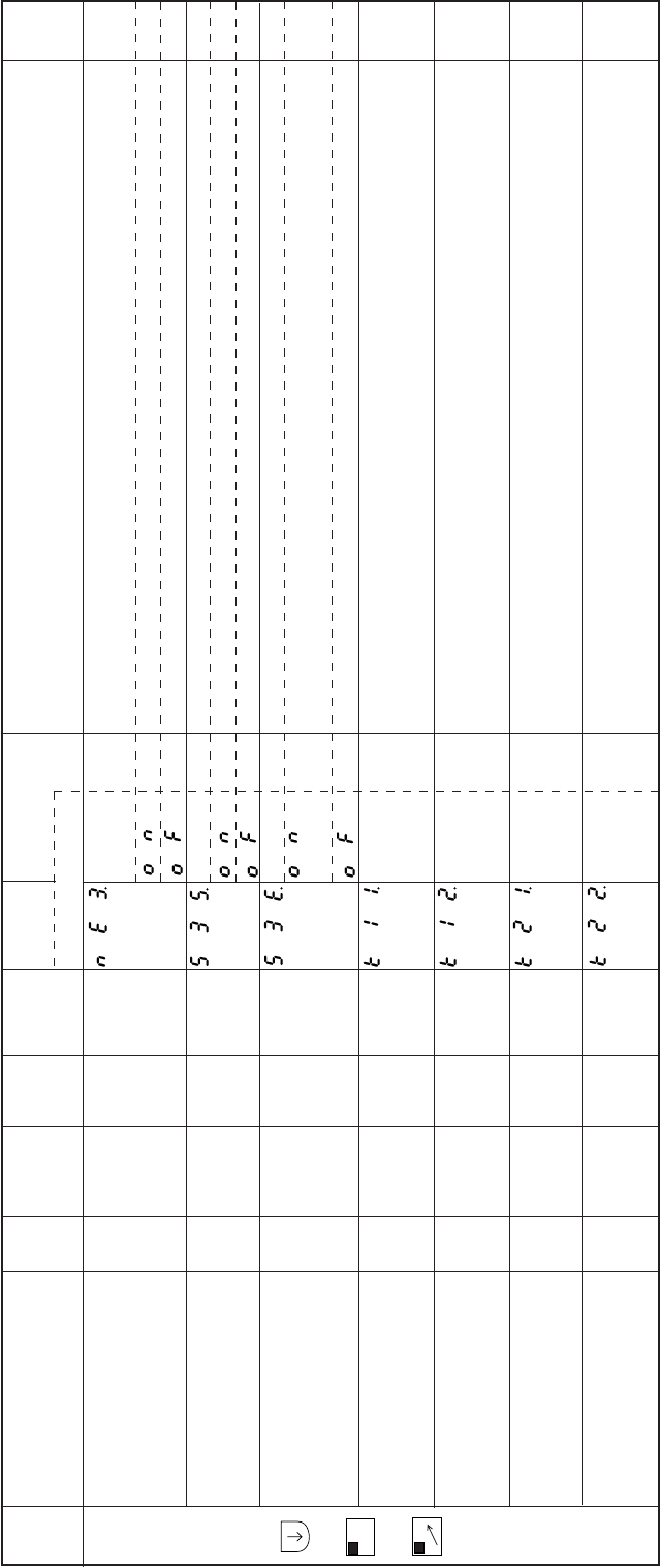
− 124 −
Mode
name Function name Oper
ability
Factory
setting Unit Setting
range Digital display
Function
name Setting Specification Ref.
page
S
mode
+
B
SL
+
D
Selection stitch amount and time till OFF for simple sequence output “KS3” (Amount have to be set
at “K22”)
Stitch amount is counted till OFF
Time is counted till OFF (10 mill-second per each)
Setting start condition of counting till ON for simple sequence output “KS3”.
When Input signal “I6” become ON after the count start condition was established, counting will start.
When the count start condition is established, counting will start.
Setting start condition of counting till OFF for simple sequence output “K3”.
When Input signal “I6” become OFF after the count start condition was established, counting will
start.
When the count start condition is established, counting will start.
The output start time/output start No. of stitches for the simple sequence output KS1 can be set.
When using time, the setting value will be (7) x10=70 msec. When using No. of stitches, the setting
value will be (7) x1=7 stitches.
The output time/output start No. of stitches for the simple sequence output KS1 can be set. When
using time, the setting value will be (7) x10=70 msec. When using No. of stitches, the setting value
will be (7) x1=7 stitches.
The output start time/output start No. of stitches for the simple sequence output KS2 can be set.
When using time, the setting value will be (7) x10=70 msec. When using No. of stitches, the setting
value will be (7) x1=7 stitches.
The output time/output start No. of stitches for the simple sequence output KS2 can be et. When
using time, the setting value will be (7) x10=70 msec. When using No. of stitches, the setting value
will be (7) x1=7 stitches.
KS3 : Selection of NE3.
Stitch amount and time till OFF
KS3 : Setting of count S3S.
condition till ON
KS3 : Setting of count S3E.
condition till OFF
KS1 output start K11.
[Time]/[No. of stitches] setting
KS1 output K12.
[Time]/[No. of stitches] setting
KS2 output start K21.
[Time]/[No. of stitches] setting
KS2 output K22.
[Time]/[No. of stitches] setting
O
O
O
O
O
O
O
OF
OF
OF
7
7
7
7
–
–
–
x10
msec
stitch
x10
msec
stitch
x10
msec
stitch
x10
msec
stitch
–
–
–
0 to 99
0 to 99
0 to 99
0 to 99
ON
OF
ON
OF
ON
OF
**
**
**
**
**
**
**
**
–
–
–
–
–
–
–
–
–
–
–
–
–
Note) For the details of each function, refer to 15. SIMPLE SEQUENCE.
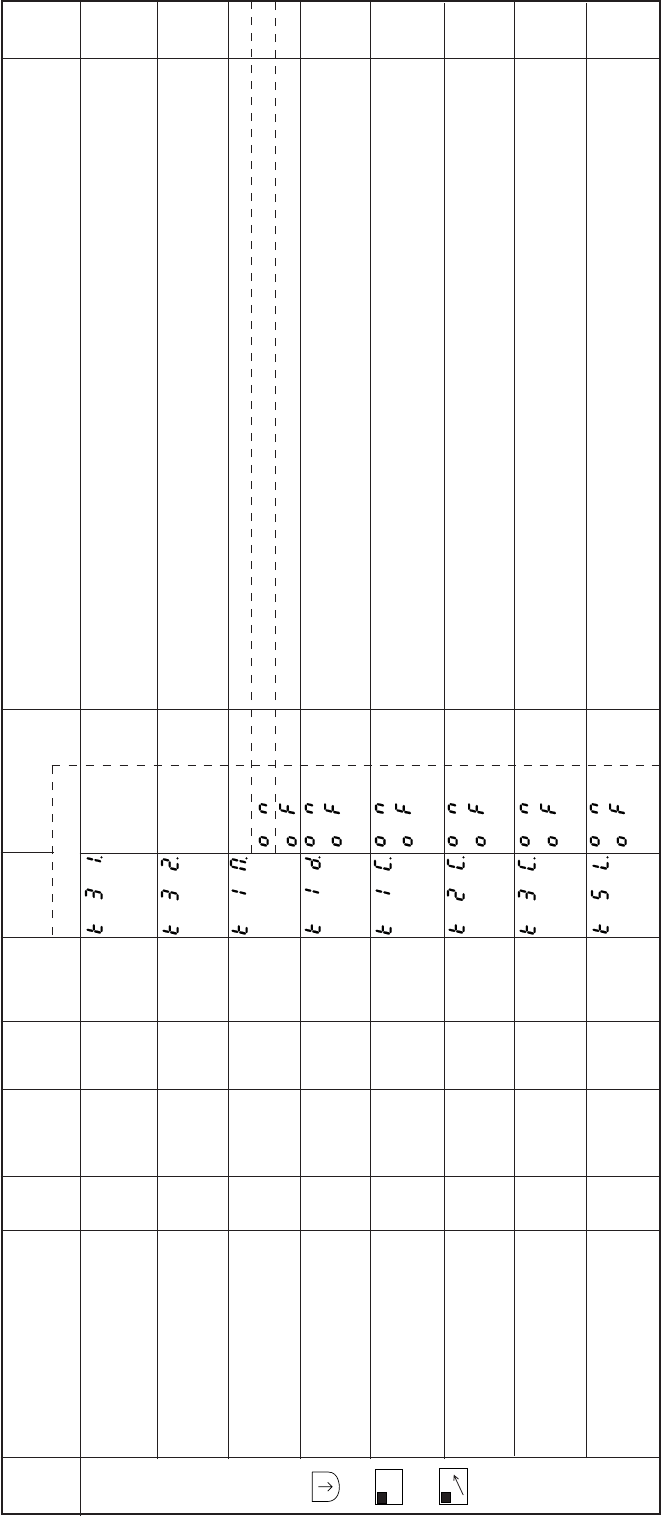
− 125 −
Mode
name Function name Oper
ability
Factory
setting Unit Setting
range Digital display
Function
name Setting Specification Ref.
page
S
mode
+
B
SL
+
D
The output start time/output start No. of stitches for the simple sequence output KS3 can be et.
When using time, the setting value will be (7) x10=70 msec. When using No. of stitches, the setting
value will be (7) x1=7 stitches.
The output time/output start No. of stitches for the simple sequence output KS3 can be et. When
using time, the setting value will be (7) x10=70 msec. When using No. of stitches, the setting value
will be (7) x1=7 stitches.
This is the output KS1 run mode for when the simple sequence start conditions [SQS] are set to NO.
The KS1 output is output each time the start conditions are established.
The KS1 output is output each time the start conditions are established after thread trimming.
Running is prohibited while the output KS1 is ON. (This is valid only when the simple sequence start
conditions [SQS] are set to NO.)
The K11 and K12 timers will be cleared and the KS1 output will be turned OFF when the sewing
machine stop (motor turns OFF) even when the output KS1 timer is continuing. (This is valid only
when the simple sequence start conditions [SQS] are set to NO.)
The K21 and K22 timers will be cleared and the KS1 output will be turned OFF when the sewing
machine stop (motor turns OFF) even when the output KS2 timer is continuing. (This is valid only
when the simple sequence start conditions [SQS] are set to NO.)
The K31 and K32 timers will be cleared and the KS1 output will be turned OFF when the sewing
machine stop (motor turns OFF) even when the output KS3 timer is continuing. (This is valid only
when the simple sequence start conditions [SQS] are set to NO.)
Increase the number of K11 through K33 by ten. (ex. 10 mS=>100 mS, note: Stitch number is not
changed.)
KS3 output start K31.
[Time]/[No. of Stitches] setting
KS3 output K32.
[Time]/[No. of Stitches] setting
KS1 output run mode K1M.
Run prohibit during K1D.
KS1 output ON
K11,K12 time clear K1C.
during KS1 output ON
K21,K22 time clear K2C.
during KS1 output ON
K31,K32 time clear K3C.
during KS1 output ON
Increase the number KSL.
of K11 through K33 by ten
O
O
X
O
O
O
O
O
7
7
ON
OF
OF
OF
OF
OF
x10
msec
stitch
x10
msec
stitch
–
–
–
–
–
–
0 to 99
0 to 99
–
–
–
–
–
–
**
**
ON
OF
ON
OF
ON
OF
ON
OF
ON
OF
ON
OF
**
**
–
–
–
–
–
–
–
–
–
–
Note) For the details of each function, refer to 15. SIMPLE SEQUENCE.
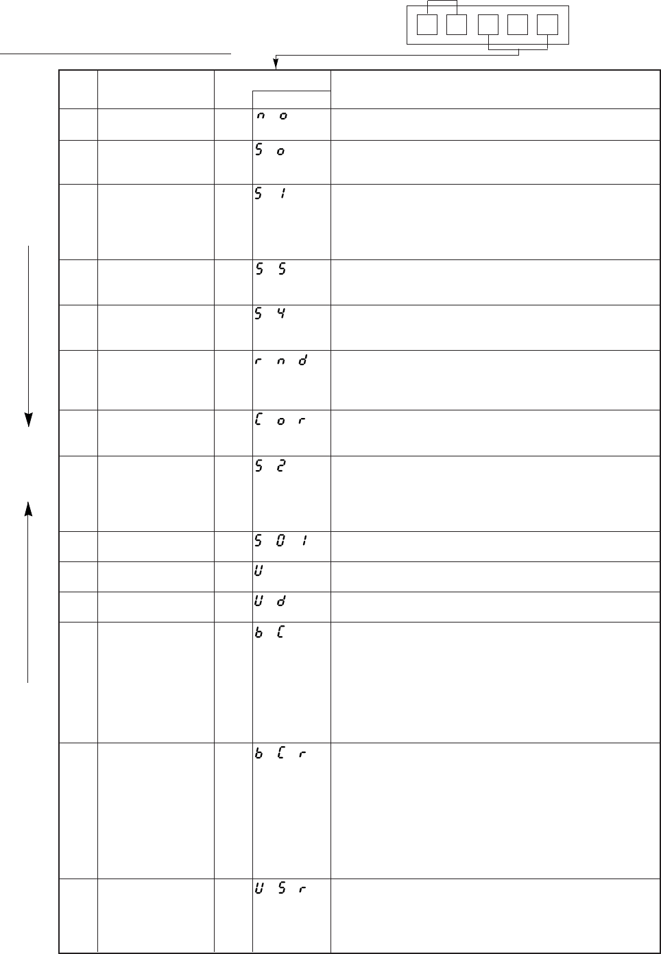
− 126 −
21. INPUT/OUTPUT FUNCTION FOR SIGNAL ON C MODE SETTING
1. C mode input signal setting table
Input signal
I A. P S U
Example
Specification
The sewing machine will do nothing even if input NO is turned ON.
If input S0 is turned ON, the sewing machine will run at the speed
set in low speed L.
This signal is equivalent to full toe down when using the pedal.
It is operated at the speed which was set with the [C, <= =][D, =
=>] key of operation panel when the automatic operation AT is ON
input S1 at the time of ON.
If input S5 is turned ON, the sewing machine will run at the speed
set in medium speed M.
If input S4 is turned ON, the sewing machine will rum at the speed
set in high speed H.
If input RND is turned ON, the sewing machine will run at the
speed set in low speed L, and when stopping the sewing machine
will stop at random regardless of the needle position.
If input COR is turned ON, correction stitching will be preformed at
the speed set in low speed L.
This signal is equivalent to full heeling when using the pedal.
When S2 is ON and thread trimming or needle UP position stop
has been competed, the wiper will operate. After that, the automatic
presser foot lifting will function while the signal is ON.
If input S01 is turned ON, 1 stitch operation will start.
If input U is turned ON, the needle lift operation will start.
If input UD is turned ON, half-stitch operation will start.
The needle is stopped just above the fabric to confirm the fabric
puncture position. Each time the signal turns ON, the operation
will alternate between forward-reverse-forward run. If the pedal is
toed down or the external run signal (S1) turns ON after that, forward
run will start form that position. The needle position stop angle can
be set with needle position stop angle C8 in the [P] mode.
The needle is stopped just above the fabric to confirm the fabric
puncture position. Each time the signal is turned ON, the operation
will alternate between forward-reverse-forward run. If the pedal is
toed down or the external run signal (S1) turns ON after stopping
at a forward run position, forward run will start after reverse run. If
stopped at a reverse run position, the sewing machine will forward
run form that position. The needle position stop angle can be set
with needle position stop angle C8 in the [P] mode.
Reverse run needle lift will be performed to the set angle.
The set angle can be adjusted from the DOWN position to UP
position with reverse run angle K8 in the [P] mode.
This is effective for blind stitch sewing machine.
No.
1
2
3
4
5
6
7
8
9
10
11
12
13
14
Setting name
Nothing signal
Low speed run signal
Variable speed run
signal
Medium speed run
signal
High speed run signal
Stop position random
run signal
Correction stitching
signal
Thread trimmer signal
1 stitch signal
Needle lift signal
Half-stitch signal
Constant angle
[reverse run/forward
run] signal
Constant angle
[reverse run/forward
run] signal
Constant angle
reverse run signal
Setting value
NO
S0
S1
S5
S4
RND
COR
S2
S01
U
UD
BC
BCR
USR
Digital display
Note) 1. The setting name will display in the descending order with each press of the [D] key.
2. The setting name will display in the ascending order with each press of the [C] key.
Note 1
Note 2
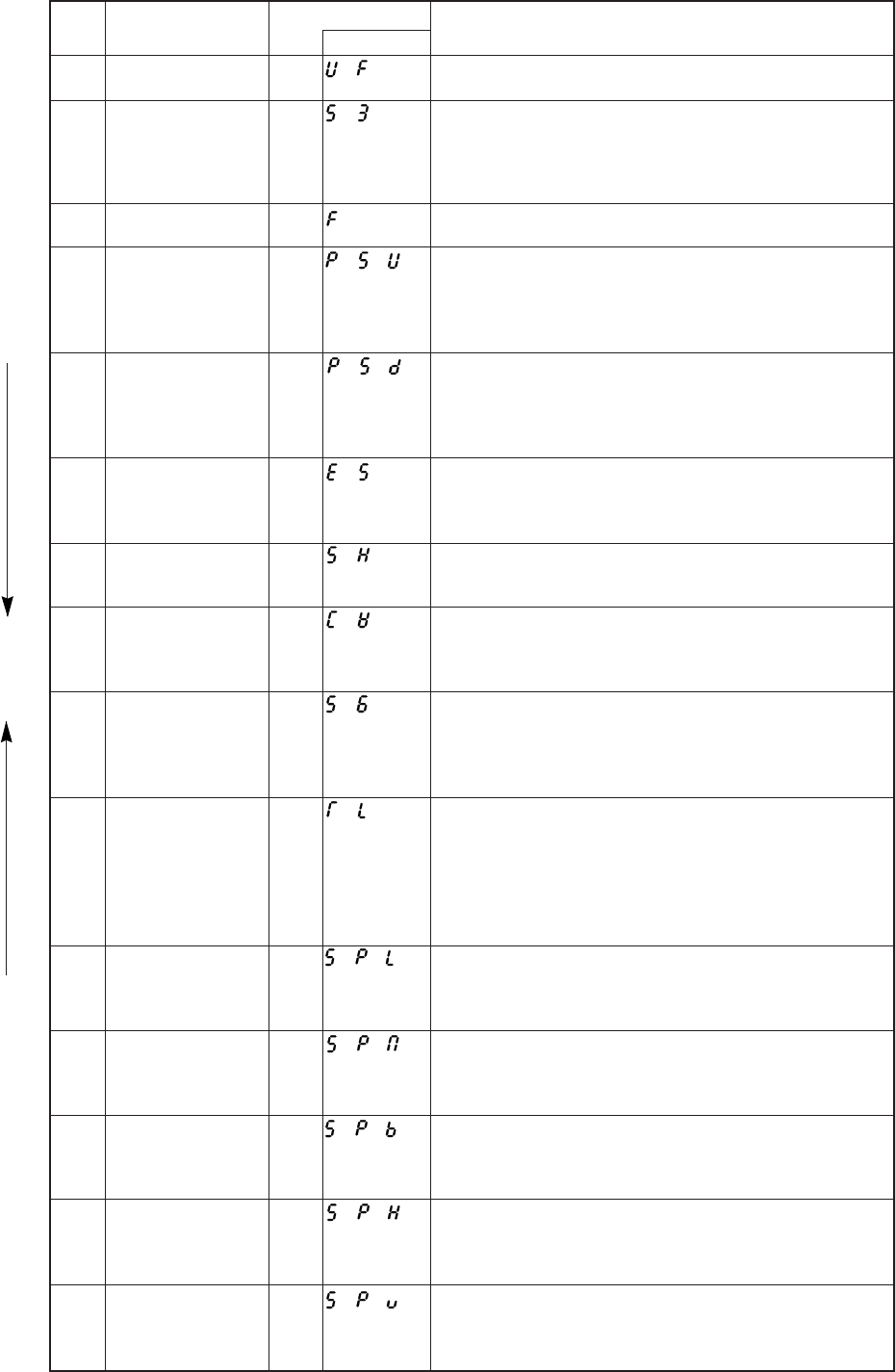
− 127 −
Specification
If input UF is turned ON, the presser foot will lift after needle lifting.
If input S3 is turned ON after trimming, the presser foot will lift.
If input S3 is turned ON before triming, the presser foot will lift after
delay time.
The delay time is set by S3D the [P] mode of the 74 page.
If input F is turned ON, the presser doot lifter operation will start.
If input PSU is turned ON while the sewing machine is running,
the needle will stop at the UP position after swing PSU stitches
and thread trimming. The no. of stitches after PSU input is set by
PSU the [P] mode of 73 page.
If input PSD is turned ON while the sewing machine is running,
the needle will stop at the DOWN position after swing PSD stitches
and thread trimming. The no. of stitches after PSD input is set by
PSU the [P] mode of 73 page.
If input ES is turned ON while the sewing machine is running, all
running states will be canceled, and the sewing machine will stop
with the brakes.
If input SH is turned ON, one shot operation will start.
The operation mode set in [P] mode SHM function will be entered.
If input CW is turned ON while running with pedal toe down or
external run signal, reverse run will be enabled while the signal is
ON.
If input S6 is turned ON while the sewing machine is running, the
sewing machine will stop. If input S6 is turned ON during thread
trimming, the operation will be completed, and operation will not
be possible until input S6 is turned OFF.
If pedal full heeling or thread trimmer signal S2 is turned ON while
input TL is ON, the thread will not be trimmed.
After the thread trimmer interlock time passes, the presser foot
lifting operation will start.
When TL of [D] mode signal is turned ON a little time and TLS
setting is ON, next thread trimming is prohibited at once.
If input SPL is turned ON while the sewing machine is running, the
sewing machine will run at the speed set in low speed setting L
while the signal is ON.
If input SPM is turned ON while the sewing machine is running,
the sewing machine will run at the speed set in medium speed
setting M while the signal is ON.
If input SPB is turned ON while the sewing machine is running, the
sewing machine will run at the speed set in end tacking speed
setting V while the signal is ON.
If input SPH is turned ON while the sewing machine is running,
the sewing machine will run at the speed set in high speed setting
H while the signal is ON.
If input SPV is turned ON while the sewing machine is running, the
sewing machine will run at the speed proportional to the variable
speed voltage VC while the signal is ON.
No.
15
16
17
18
19
20
21
22
23
24
25
26
27
28
29
Setting name
Needle lift, presser
foot lift signal
Presser foot lifter
signal
Presser foot lifter signal
Needle UP position
priority stop signal
Needle DOWN
position priority stop
signal
Emergency stop
signal
One shot signal
Reverse run signal
Thread trimmer
protection signal
Thread trimmer cancel
signal
Low speed signal
Medium speed signal
End tacking speed
signal
High speed signal
Variable speed signal
Setting value
UF
S3
F
PSU
PSD
ES
SH
CW
S6
TL
SPL
SPM
SPB
SPH
SPV
Digital display
Note) 1. The setting name will display in the descending order with each press of the [D] key.
2. The setting name will display in the ascending order with each press of the [C] key.
Note 1
Note 2
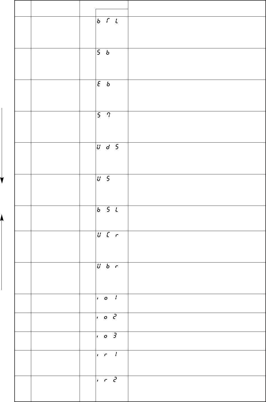
− 128 −
Specification
IIf input BTL is turned ON, start and end tacking will be prohibited
while the signal is ON.
When BTS of [D] mode is ON, and BTL signal is turned ON a little
time, next tacking is prohibited at once.
If input SB is turned ON, start tacking will be prohibited while the
signal is ON.
When BS of [D] mode is ON, and SB signal is turned ON a little
time, next start tacking is prohibited at once.
If input EB is turned ON, end tacking will be prohibited while the
signal is ON.
When BS of [D] mode is ON, and EB signal is turned ON a little
time, next end tacking is prohibited at once.
If input S70 is turned ON while the sewing machine is running,
backstitching (reverse feed) will start.
Nothing will happen if input S70 is turned ON while the sewing
machine is stopped.
If input UDS is turned ON while the sewing machine is running,
backstitching (reverse feed) will start.
Half-stitch operation will start if input UDS is turned ON while the
sewing machine is stopped.
If input US is turned ON while the sewing machine is running,
backstitching (reverse feed) will start.
Half-stitch operation will start if input US is turned ON while the
sewing machine is stopped.
If input BSL is turned ON when the sewing machine is running or
stopped, backstitching (reverse feed) will start.
If input UCR is turned ON while the sewing machine is running,
backstitching (reverse feed) will start.
1 stitch operation will start if input UCR is turned ON while the
sewing machine is stopped.
If input UBR is turned ON while the sewing machine is running,
backstitching (reverse feed) will start.
1 stitch operation with backstitching (reverse feed) will start if input
UBR is turned ON while the sewing machine is stopped.
If input I01 is turned ON, output OT1 will always be turned ON.
If input I02 is turned ON, output OT2 will always be turned ON.
If input I03 is turned ON, output OT3 will always be turned ON.
If input IR1 is turned ON, output OT1 turns ON only when the
sewing machine is running.
If input IR2 is turned ON, output OT2 turns ON only when the
sewing machine is running.
No.
30
31
32
33
34
35
36
37
38
39
40
41
42
43
Setting name
Tacking cancel signal
Start tacking cancel
signal
End tacking cancel
signal
Backstitching during
run signal
Backstitching during
run signal
Backstitching during
run signal
Backstitching signal
[when running when
stopped.]
Backstitching signal
when running
Backstitching signal
when running
Signal output to virtual
output 1
Signal output to virtual
output 2
Signal output to virtual
output 3
Signal output to
virtual output 1 during
operation
Signal output to
virtual output 2 during
operation
Setting value
BTL
SB
EB
S7
UDS
US
BSL
UCR
UBR
IO1
IO2
IO3
IR1
IR2
Digital display
Note) 1. The setting name will display in the descending order with each press of the [D] key.
2. The setting name will display in the ascending order with each press of the [C] key.
Note 1
Note 2
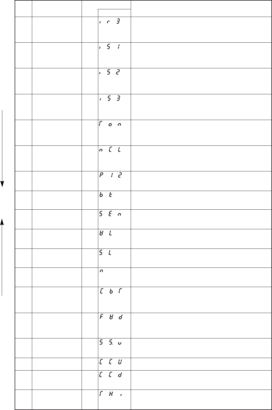
− 129 −
Specification
If input IR3 is turned ON, output OT3 turns ON only when the
sewing machine is running.
If input IR1 is turned ON, output OT1 turns ON only when the
sewing machine is stopped.
If input IR2 is turned ON, output OT2 turns ON only when the
sewing machine is stopped.
If input IR3 is turned ON, output OT3 turns ON only when the
sewing machine is stopped.
The thread trimmer output T can be turned ON or OFF only when
the sewing machine is stopped.ÅiThread trimmer solenoid
confirmation signalÅj
If input NCL is turned ON, the needle cooler output NCL during
sewing machine rotation will forcibly by turned OFF.
1 position will be set forcibly.
If input BK is turned ON, the weak brake will turn ON. Use this with
the BK of the [D] mode set to [OF].
This is the cloth edge sensor input.
If input WL is turned ON, the wiper output W will not be output.
If the SL signal is ON, the slow start operation will be valid. Use
this with the normal mode [B,SL] key set to [OF].
If input N is turned ON,preset stitching will start forcibly from that
point.
If input CBT is turned ON, continuous backstitching will start forcibly
from that point.
If input FWD is turned ON, output OT3, output NCL and output FU
will be turned ON forcibly. Output ROL and output PUL will be
turned OFF forcibly.
If input S5V is turned ON, the sewing machine will run at the speed
set in end tacking speed V.
If input CCU is turned ON, it clears the UP counter only.
If input CCD is turned ON, it clears the DOWN counter only.
It can be used as the input signal of needle thread break detector.
No.
44
45
46
47
48
49
50
51
52
53
54
55
56
57
58
59
60
61
Setting name
Signal output to
virtual output 3 during
operation
Signal output to
virtual output 1 when
stopped
Signal output to
virtual output 2 when
stopped
Signal output to
virtual output 3 when
stopped
Thread trimmer output
confirmation signal
Needle cooler output
during rotation forced
[OFF] signal
1 position priority
signal
Weak brake [ON]
signal
Sensor input signal
Wiper output cancel
signal
Slow start signal
Preset stitching forced
[ON] signal
Continuous tack
stitching forced [ON]
signal
Non-stitching feed
input
End tacking speed run
signal
Count-UP clear signal
Count-DOWN clear
signal
Needle thread break
detector input signal
Setting value
IR3
IS1
IS2
IS3
TON
NCL
P12
BK
SEN
WL
SL
N
CBT
FWD
S5V
CCU
CCD
THI
Digital display
Note) 1. The setting name will display in the descending order with each press of the [D] key.
2. The setting name will display in the ascending order with each press of the [C] key.
Note 1
Note 2
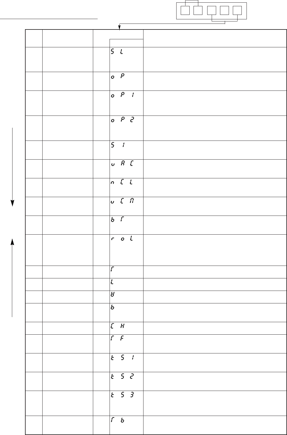
− 130 −
Output signal
0A T
Example
Specification
During the no. of the setting needles, SL output is turned ON.
The setting no. of needles can select SLN on [P] mode of H0Fon
[G] mode by setting SLH on [F] mode
OP output is turned ON while the sewing machine is running.
(not including needle lifting during thread trimming).
OP1 output is turned ON while the sewing machine is running.
(not including needle lifting during thread trimming).
OP1 output will turn ON during needle lifting when directly heeling.
OP1 output is turned ON while the pedal is toed dawn, the external
operation signal (S0, S1, SH), full pedal heelimg or thread trimming
signal (S2) is ON.
S1 output is turned ON when the run signal is ON except during
on 1 stitch sewing.
VAC output is turned ON during pedal full heeling or while thread
trimmer signal S2 is ON.
NCL output is turned ON while the sewing machine is running
(including needle lifting).
VCM output is turned ON during pedal full heeling or while thread
trimmer signal S2 is ON while the sewing machine is stopped.
BT output is turned ON during tacking.
ROL output is turned ON when presser foot lifter output FU is ON,
backstitching output B is ON, or when input IO2 signal is ON.
ROL output is turned ON while tacking and while thread trimming
if RLM of [F] mode is ON.
Thread trimming starts.
Thread release operation starts.
Wiper operation starts.
Backstitching (reverse feed) starts.
(Condensed stitch)
CH2 Output for chain stitches.
TF output for chain stirches.
Refer to “Output TB,TF timings”.
Behind operation signal ON, KS1 output is turned ON after the
setting delay time. Refer to “Output KS1,KS2,KS3 timings”.
After the motor stopped, KS1 output is turned ON after the setting
delay time. Refer to “Output KS1, KS2, KS3 timings”.
After trimming and stopped up position, KS3 output is turned ON
after setting delay time.
Refer to “Output KS1,KS2,KS3 timings”.
TB Output for chain stitches.
Refer to “Output TB,TF timings”.
No.
1
2
3
4
5
6
7
8
9
10
11
12
13
14
15
16
17
18
19
20
Setting name
Output for slow start
Run output 1
Run output 2
Run output 3
Output for run signal
Output for blower
Output for needle
cooler
Output for vacuum
signal
Output for signal
during tacking
Roller lift output
Thread trimmer output
Thread release output
Wiper output
Backstitch output
(Condensed stitch)
[CH2] output
[TF] output
[KS1] output
[KS2] output
[KS3] output
[TB] output
Setting value
SL
OP
OP1
OP2
S1
VAC
NCL
VCM
BT
ROL
T
L
W
B
CH
TF
KS1
KS2
KS3
TB
Digital display
Note 1
Note 2
C mode output signal setting table
Note) 1. The setting name will display in the descending order with each press of the [D] key.
2. The setting name will display in the ascending order with each press of the [C] key.
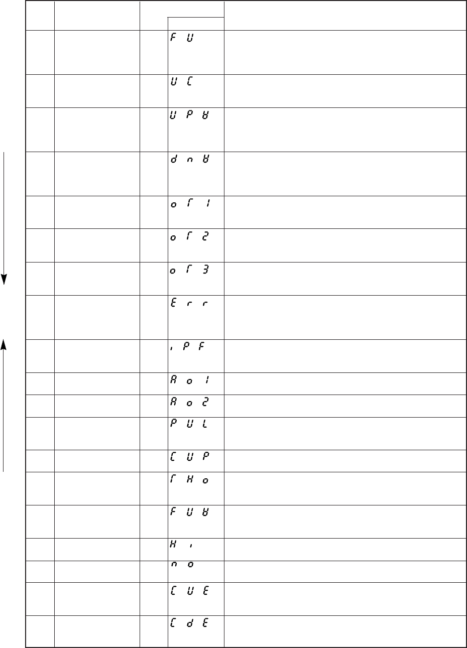
− 131 −
Specification
Presser foot lifter operation starts.
The operation mode set in the [P] mode FUM function and FU
function will be entered.
UC output is turned ON if at the needle UP position when the
sewing machine is stopped.
UPW output is turned ON if at the UP position when the, sewing
machine is stopped, and while moving from the UP position to the
DOWN position when the sewing, machine is running.
DNW output is turned ON if at the DOWN position when the, sewing
machine is stopped, and while moving from the DOWN position to
the UP position when the sewing, machine is running.
OT1 output is turned ON according to each input specifications
while inputs IO1,IR1 and IS1 are ON.
OT2 output is turned ON according to each input specifications
while inputs IO2,IR2 and IS1 are ON.
OT3 output is turned ON according to each input specifications
while inputs IO3,IR3 and IS1 are ON.
This is output when an error occurs. (Note that this is not output
when error code E9 occurs.)
When power is turned OFF, IPF output is turned ON.
(Not used)
Not used
Not used
PUL output is turned ON during the presser foot lifter operation,
during the IO2 output is ON.
When +1 up counter does, the [CUP] output is turned on.
When detecting thread break detector, THO output is turned ON
(When re-operation, the signal is turned off)
FUW output is turned ON during the presser foot lifter operation or
during wiper operation.
In case of the power on, [HI] output is always ON.
Nothing is output.
This output becomes ON when Up-counter becomes end.
This output becomes OFF when “CCL” input is turned on.
This output becomes ON when Down-counter becomes end.
This output becomes OFF when “CCL” input is turned on.
No.
21
22
23
24
25
26
27
28
29
30
31
32
33
34
35
36
37
38
39
Setting name
Presser foot lifter
output
Output for UP position
when stopped
Needle UP position
output
Needle DOWN
position output
Virtual output 1
Virtual output2
Virtual output3
Output for error
occurrence
confirmation
Output for power
[OFF] confirmation
[A01] output
[A02] output
Puller output
Count up output
Thread break detector
output
Vacuum output for
holding thread
Always ON output
[NO] output
[CUE] output
[CDE] output
Setting value
FU
UC
UPW
DNW
OT1
OT2
OT3
ERR
IPF
AO1
AO2
PUL
CUP
THO
FUW
HI
NO
CUE
CDE
Digital display
Note 1
Note 2
Note) 1. The setting name will display in the descending order with each press of the [D] key.
2. The setting name will display in the ascending order with each press of the [C] key.
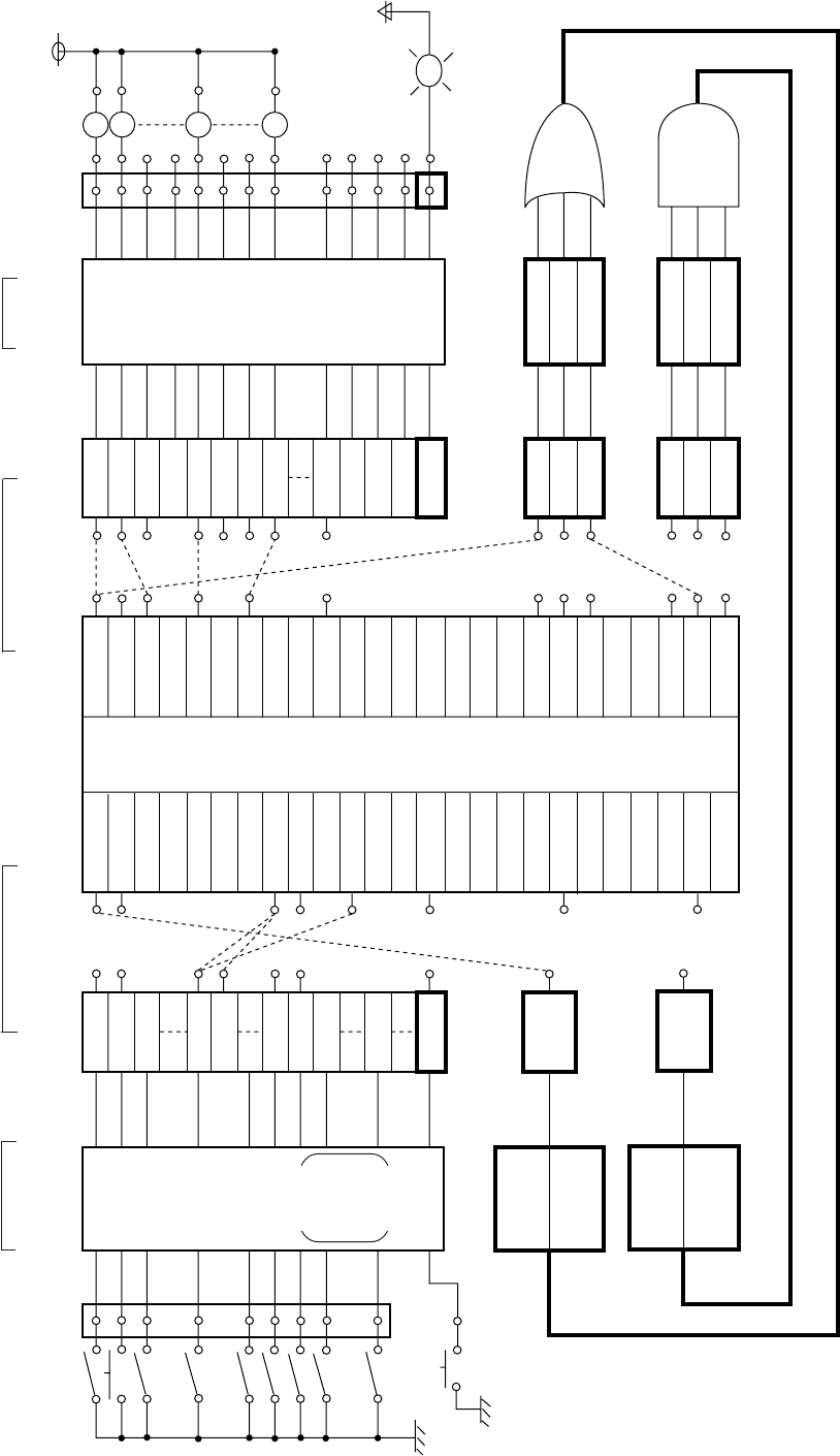
− 132 −
22. THE COMPOSITION FIGURE OF INPUT AND OUTPUT CUSTOMIZATION
1. Input and output customization
AND module
Setting the logic of input
signal on program mode Setting Input
function Setting output function
on program mode C Setting the logic
of output signal
Panel
connector
(Input port)
Input control
section
F/F
Alternate
Reverse
RS flip
flop is
11,12
only
Logical
Input
IA
IB
IC
IF
IG
I1
I2
I4
I7
IP
Virtual
input
IO1
IO2
IR1
S1
F
UBR
NO
Virtual
output
T
L
W
FU
OT1
KS1
ROL
HI
NO
Logical
output
OA
OB
OC
OD
OF
O1
O2
O3
O7
OJ
OK
OO
OP
Output
control
Reverse
Chopping
Off timer
On delay
etc.
Connector
(Output port)
OA
OB
OF
O3
P
“P” switch on
control panel Reverse
(ORL)
Alternative
(ORA)
Reverse
(ANL)
Alternative
(ANA)
OR
AN
R1
R2
R3
Reverse
R1L
R2L
R3L
Reverse
N1L
N2L
N3L
N1
N2
N3
LED of “P”
switch on
control panel
OR module
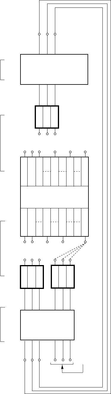
− 133 −
2. Input/output direct coupling port (inside connecting port)
OUT-J
* The factory settings of the input function settings [IJ], [IK], [IO] and [IL], [IM], [IN] are all [NO].
* The factory settings of the output function settings [OJ], [OK], [OIO] are all [NO].
* The input function settings [IL], [IM], [IN] must not be used with the default setting [NO].
Setting the logic of input
signal on program mode Setting Input
function Setting output function
on program mode C Setting the logic of
output signal
IN-J
IN-K
IN-O
IN-L
IN-M
IN-N
* Not used
Input control
section
Reverse
Alternate
F/F
Logical
Input
IJ
IK
IO
IL
IM
IN
Virtual
input
IO1
IO2
IR1
S1
NO
Sewing
machine
control
Virtual
output
T
L
W
FU
OT1
NO
Logical
output
OJ
OK
OO
Output
control
Chopping
Reverse
Off timer
On delay
etc.
OUT-K
OUT-O
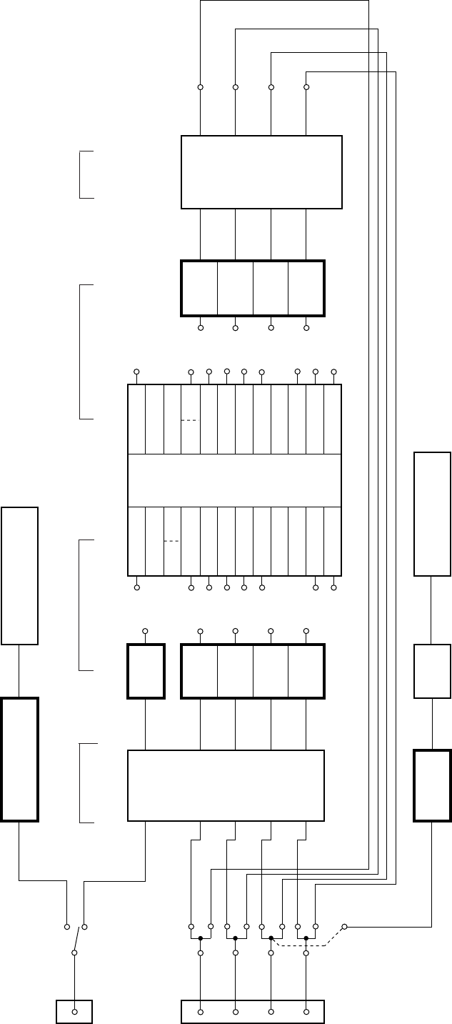
− 134 −
3. Connector input/output common port
Note) Option B connector input/output common port
When changing the input/output, set the output side to [NO] to use the port for inputs and set the input side to [NO] to use the port for outputs. The default settings are
all [NO].
(For example, if the option B connector No.2 pin is to be set to input, set the OUT4, or [O4] function to [NO], and set the required input function in IN4, or [I4] function.)
The above input/output common port is connected internally, so if a function other than [NO] is set on both the input side and output side, the output side setting will
affect the input side.
Sewing machine
control
* The CP output is enabled with the CPK [OF] setting in the C mode.
* The division rate can be with the division rate setting [CP] in the [C] mode.
(When the setting has been changed, turn the power OFF and ON once.)
Connector
input/output
common port
6
Option A
(CKK=OF)
CKD
IN-C
(CKK=ON)
* The CKD output enabled with the CKK [OF] setting in the C mode.
CKD output Detector Down Signal
Setting the logic of input
signal on program mode Setting Input
function Setting output function
on program mode C Setting the logic of
output signal
2
5
14
13
Option B
IN4
OUT4
IN5
OUT5
IN6
OUT6
IN7
OUT7
CP
(CPK=OF)
Input control
section
Reverse
Alternate
F/F
Logical
Input
IC
I4
I5
I6
I7
Virtual
input
IO1
IO2
IR1
S1
NO
Sewing
machine
control
Virtual
output
T
L
W
FU
OT1
NO
Logical
output
O4
O5
O6
O7
Output
control
Chopping
Reverse
Off timer
On delay
etc.
OUT4
OUT5
OUT6
OUT7
CP output Setting
division
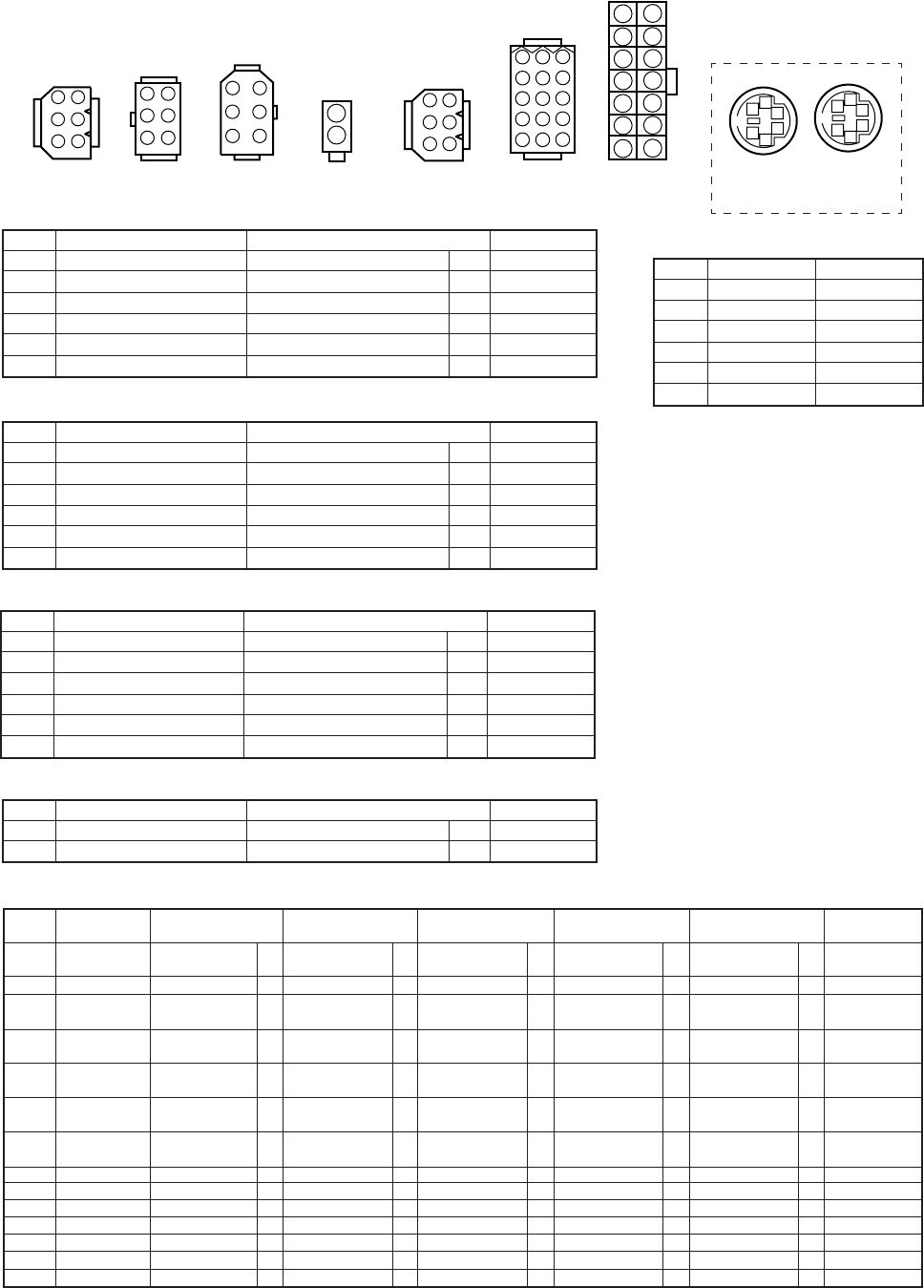
− 135 −
23. HOW TO USE THE OPTION CONNECTOR
Variable operation are possible by adding external signals to the option connector.
A current of approximately 1.5mA flows through the switches used for the input signal, so please use
switch for minute current.
1) Connector layout
1
2
3
4
5
6
4
5
6
1
2
3
4
5
6
1
2
3
1
2
3
4
5
6
3
6
9
2
5
8
1
4
7
121110
1514
13
147
136
125
114
103
92
81
1
2
3
4
5
6
1
2
3
4
5
6
Communication
Operation panel
Lever Encoder Detector Foot lifter Option A Option B Sewing
machine
1
2
Lever connector (white)
Setting function
0V
Run signal
Thread trimming signal
Presser foot lifter signal
Variable speed signal
+12V
No.
1
2
3
4
5
6
Physics input port name
IG
IH
II
VC
Remarks
S1
S2
S3
VC
Remarks
Functions set to the sewing machine connectors vary in accordance with the sewing machine heads selected.
(Make sure of the simple selecting table for the sewing machine heads, 9-3) Program modes [1] and [2], and the marks described
under the setting functions.)
Operation panel/Communication
No.
1
2
3
4
5
6
Signal name
RXD
–
TXD
0V
+12V
–
Encoder
Setting function
0V
Phase A signal
Phase B signal
+12V
Ground
–
No.
1
2
3
4
5
6
Physics input port name Remarks
EA
EB
Detector
Setting function
0V
–
Ground
UP position detection
DOWN position detection
+12V
No.
1
2
3
4
5
6
Physics input port name Remarks
UP
DN
Presser foot lifter
Setting function
Presser foot lifter output
Presser foot lifter output
No.
1
2
Physics input port name
OF
OF
Remarks
FU-
FU+
No.
1
2
3
4
5
6
7
8
9
10
11
12
13
14
Sewing machine
Physics input
port name
0A
0B
ID
IF
IE
0C
0D
Setting function
(A, C, D, E, F, G, H, I, J, O)
Thread trimmer
output
Wiper output
Thread trimmer
cancel signal
Presser foot lifter
signal
Backstitching
signal
Backstitching
output
Sub-back output
+24V
+24V
Ground
0V
0V
+24V
+24V
Setting function (B)
Thread trimmer
output
Wiper output
Thread trimmer
cancel signal
Presser foot lifter
signal
Backstitching
signal
Backstitching
output
Sub-back output
+24V
+24V
Ground
0V
0V
+24V
+24V
Setting function (K, M)
Thread trimmer
output
Wiper output
Thread trimmer
protection signal
Presser foot lifter
signal
Thread trimmer
cancel signal
Needle cooler
output
Lower thread
remove output
+24V
+24V
Ground
0V
0V
+24V
+24V
Setting function (L)
Thread trimmer
output
Wiper output
Thread trimmer
protection signal
Presser foot lifter
signal
Thread trimmer
cancel signal
Needle cooler
output
Thread trimmer
output
+24V
+24V
Ground
0V
0V
+24V
+24V
RemarksSetting function (N)
Thread trimmer
output
Wiper output
Thread trimmer
protection signal
Presser foot lifter
signal
Thread trimmer
cancel signal
Needle cooler
output
Thread release
output
+24V
+24V
Ground
0V
0V
+24V
+24V
T
W
TL
F
S7
B
L
T
W
U
F
S7
B
L
T
W
S6
F
TL
NCL
SL
T
W
S6
F
TL
NCL
T
T
W
S6
F
TL
NCL
L

− 136 −
Connector E (Option A : Black)
Setting function (K, L, M, N)
0V
Needle UP position priority
stop signal
+12V
Needle DOWN position
priority stop position
Needle UP position output
Thread trimmer protection
signal
No.
1
2
3
4
5
6
Physics input port name
IA
IB
IC
Setting function (A, B, C, D, F, I, O)
0V
Needle UP position priority
stop signal
+12V
Needle DOWN position
priority stop signal
Needle UP position output
Low speed run signal
Setting function (E)
0V
I05 input siganl
+12V
Needle DOWN position
priority stop signal
Needle UP position output
Low speed run signal
Setting function (G, H)
0V
Thread trimmer safe signal
+12V
Needle DOWN position
priority stop signal
Needle UP position output
Low speed run signal
Setting function (J)
0V
Emergency stop signal
+12V
Needle DOWN position
priority stop signal
Needle UP position output
Low speed run signal
Remarks
PSU
PSD
CKU
SO
IO5
PSD
CKU
SO
S6
PSD
CKU
SO
ES
PSD
CKU
SO
PSU
PSD
CKU
S6
Setting function (E)
0V
OT1 output
OT5 output
Variable speed command
Thread trimmer output
I01 input signal
+12V
+24V
Needle lift signal
0V
+24V
OT4 output
KS1 output
–
OT3 output
Connector G (Option B)
No.
1
2
3
4
5
6
7
8
9
10
11
12
13
14
15
Physics input port name
O4/I4
O1
VC2
O5/I5
I1
I2
O2
O7/I7
CP/O6/I6
O3
Setting function (A)
0V
–
OT1 output
Variable speed command
–
I01 input signal
+12V
+24V
Needle lift signal
0V
+24V
Needle cooler output
–
Presser foot lifter signal
TF output
Setting function (B)
0V
–
OT1 output
Variable speed command
–
I01 input signal
+12V
+24V
Needle lift signal
0V
+24V
Needle cooler output
Start/end tacking cancel signal
Presser foot lifter signal
TF output
Setting function (C)
0V
Medium speed signal
OT1 output
Variable speed command
End tacking speed signal
I01 input signal
+12V
+24V
I01 input signal
0V
+24V
Needle cooler output
Start/end tacking cancel signal
Presser foot lifter signal
TF output
Setting function (D)
0V
Medium speed signal
OT1 output
Variable speed command
End tacking speed signal
I01 input signal
+12V
+24V
Needle lift signal
0V
+24V
Needle cooler output
–
Presser foot lifter signal
TF output
Remarks
OT1
VC
IO1
U
NCL
F
TF
OT1
VC
IO1
U
NCL
BTL
F
TF
SPM
OT1
VC
SPB
IO1
IO1
NCL
BTL
F
TF
SPM
OT1
VC
SPB
IO1
U
NCL
F
TF
OT1
OT5
VC
T
IO1
U
OT4
KS1
OT3
Setting function (M)
0V
Needle cooler prohibit signal
OT1 output (Folder)
Variable speed command
Reset signal
Short stitch cancel signal
+12V
+24V
Folder input signal
0V
+24V
Short stitch output
Thread trimmer knife out signal
Non-stitching feed signal
Non-stitching feed output
No.
1
2
3
4
5
6
7
8
9
10
11
12
13
14
15
Physics input port name
O4/I4
O1
VC2
O5/I5
I1
I2
O2
O7/I7
CP/O6/I6
O3
Setting function (F, H, I, O)
0V
–
OT1 output
Variable speed command
–
I01 input signal
+12V
+24V
Needle lift signal
0V
+24V
Needle cooler output
–
–
TF output
Setting function (G)
0V
OT1 output
OT1 output
Variable speed command
–
I01 input signal
+12V
+24V
Needle lift signal
0V
+24V
OT3 output
–
–
OT2 output
Setting function (J)
0V
Constant angle signal
KS1 output
Variable speed command
–
I01 input signal
+12V
+24V
Needle lift signal
0V
+24V
Needle cooler output
–
–
TF output
Setting function (K, L, N)
0V
Needle cooler prohibit signal
OT1 output
Variable speed command
Reset signal
Short stitch cancel signal
+12V
+24V
Folder input signal
0V
+24V
Roller lift output
Thread trimmer knife out signal
Non-stitching feed signal
Non-stitching feed output
Remarks
OT1
VC
IO1
U
NCL
TF
OT1
OT1
VC
IO1
U
OT3
OT2
BC
KS1
VC
IO1
U
NCL
TF
NCL
OT1
VC
KS3
EB
IO1
ROL
TON
FWD
OT3
NCL
OT1
VC
KS3
EB
IO1
BT
TON
FWD
OT3
Functions set to the sewing machine connectors vary in accordance with the sewing machine heads selected. (Make sure of the simple selecting table for the sewing machine heads, 9 - 3) Program modes [1] and
[2], and the marks described under the setting functions.)

− 137 −
The specification
This signal is equivalent to full the down when using
the pedal. It is operated at the speed which was set
with the [C][D]key of operation panel when the
automatic operation AT is ON input S1 at the time of
ON.
This signal is equivalent to full heeling when using the
pedal.
When S2 is ON and thread trimming or needle UP
position stop has been completed, the wiper will
operate. After that, the automatic presser foot lifting
will function while the signal is ON.
If input S3 is turned ON after trimming, the presser foot
will lift.
If input S3 is turned ON before triming, the presser foot
will lift after delay time. The delay time is set by S3D
the [P] mode of the 74 page.
It is speed regulation input from outside. By giving
variable speed command voltage (0-11 V), the speed
which is proportional to the voltage is gotten.
This is the power for the variable speed command.
A DC12 V (max. 40 mA) is out put.
Wiper operation starts.
Thread trimming starts.
If pedal full heeling or thread trimmer signal S2 is turned
ON while input TL is ON, the thread will not be trimmed.
After the thread trimmer interlock time passes, the
presser foot lifting operation will start.
When TL of [D] mode signal is turned ON a little time
and TLS setting is ON, next thread trimming is
prohibited at once.
Thread release operation starts.
If input S7 is turned ON while the sewing machine is
running, backstitching (reverse feed) will start. Nothing
will happen if input S7 is turned ON while the sewing
machine is stopped.
Backstitching (reverse feed) starts.
(Condensed stitch)
If input F is turned ON, the presser foot lifter operation
will start.
Presser foot lifter operation starts. The operation mode
set in the [P] mode FUM function and FU function will
be entered.
2)The explanation of the input/output signal
Pin number
2
3
4
5
6
2
1
3
7
5
6
4
2
1
The input/output signal name
(Factory setting)
Variable speed run signal S1
Thread trimmer signal S2
Presser foot lifter signal S3
Variable speed VC
command voltage
Constant voltage
power supply +12 V
Wiper output W
Thread trimmer output T
Thread trimmer TL
cancel signal
Thread release output L
Backstitching durin S7
run signal
Backstitching output B
(Condensed stitch)
Presser foot lifter signal F
Presser foot lifter output FU+
FU-
Physics input
port name
IG
IH
II
VC
OB
OA
ID
OD
IE
OC
IF
OF
Model
name
SC-380
○
○
○
○
○
○
○
○
○
○
○
○
○
Connector
Lever connector
Sewing machine connector
Presser foot lifter

− 138 −
The specification
If input PSU is turned ON while the sewing machine is
running, the needle will stop at the UP position after
swing PSU stitches and thread trimming. The no. of
stitches after PSU input is set by PSU the [P] mode of
73 page.
The constant voltage power supply. DC +12 V (max.
40 mA)
If input PSD is turned ON while the sewing machine is
running, the needle will stop at the DOWN position
after swing PSD stitches and thread trimming. The no.
of stitches after PSD input is set by PSU the [P] mode
of 73 page.
The UP position is output. This can be used as the
signal for the stitch count, etc. The output voltage is
DC 12 V/5 V (max. 40 mA).
The factory setting is 5 V.
If input S0 is turned ON, the sewing machine will run at
the speed set in low speed L. (CKD is DOWN position
signal output It changes by the CKK setting of 92 page
C mode by S0 and CKD.)
It is also input/output serving port. When using as the
input, make O4 NO setting, and when using as the
output, make I4 NO setting.
OT1 output is turned ON according to each input
specifications while inputs IO1,IR1 and IS1 are ON.
This is the input for external speed command. By
applying the variable speed command voltage, the
speed that is relative to the voltage is obtained.
It is an also input/output serving port. When using as
the input, make O5 NO setting, and when using as the
output, make I5 NO setting.
If input IO1 is turned ON, output OT1 will always be
turned ON.
A DC 12 V is output (max.50 mA).This can be used as
the power source for the photoelectric switches in the
amplifier.
If input U is turned ON, the needle lift operation will
start.
NCL output is turned ON while the sewing machine is
running (including needle lifting).
It is an also input/output serving port. When using as
the input, make O7 NO setting, and when using as the
output, make I7 NO setting.
If input F is turned ON, the presser foot lifter operation
will start.
* Same function as that of No. 4 pin of sewing machine
connector.
TF output for chain stitches.
Refer to pages 55 and 109 for the output timing.
Pin number
2
3
4
5
6
2
3
4
5
6
7
9
12
13
14
15
The input/output signal name
(Factory setting)
Needle UP position PSU
priority stop signal
Constant voltage +12 V
power supply
Needle DOWN position PSD
priority stop signal
Needle UP position output CKU
Low speed run signal SO
The signal which NO
does nothing
Virtual output 1 OT1
Virtual speed command VC2
The signal which NO
does nothing
Signal output to IO1
virtual output 1
Rated voltage poser +12 V
Needle lift signal U
Output for needle cooler NCL
The signal which NO
does nothing
The signal which F
does nothing
[TF] output TF
Physics input
port name
IA
IB
IC/CKD
O4/I4
O1
VC2
I5/O5
I1
I2
O2
I7/O7
I6/O6/CP
O3
Model
name
SC-380
○
○
○
○
○
○
○
○
○
○
○
○
○
○
○
○
Connector
Option A connector
Option B connector
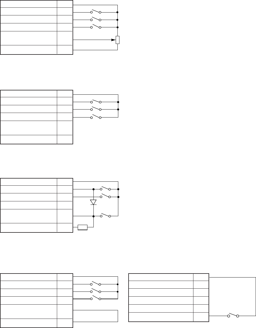
− 139 −
3) To use as a standing work type sewing machine.
The sewing machine can be used as a standing work type sewing machine with the four connections below
using the lever connector. However, take special care to the intrusion of noise, and use the shortest wiring
possible.
For the standing work, it is recommended to use JUKI PK75.
(1) When operating with an external variable resistor
(Control panel auto and AT in [P] mode is OFF)
Lever (white connector)
S1
S2
S3
VC
External variable
resistor 10 KΩ
(2) For operating with a high speed
(Control panel auto and AT in [P] mode is ON)
Lever (white connector)
S1
S2
S3
Run (High speed)
(3) When operation with high speed and inching (Control panel auto and AT in [P] mode is OFF)
(a) When using the lever connector
Lever (white connector)
S1
S2
S0
D
R
D : Equivalent to 1S953 (NEC) (VR ≧30 V, IF ≧30 mA)
R : 1 kΩ 1/2W higher
(b) When using the lever connector and option connector
Lever (white connector) Option A (black connector)
S1
S2
S3
Run
(High speed)
0V 1
2
3
4
5
Operation (low speed) 6 S0
0 V 1
Operation 2
Thread trimmer 3
Presser foot lifter 4
Variable speed 5
command
+12 V 6
0 V 1
Operation 2
Thread trimmer 3
Presser foot lifter 4
Variable speed 5
command
+12 V 6
0 V 1
Operation 2
Thread trimmer 3
Presser foot lifter 4
Variable speed 5
command
+12 V 6
0 V 1
Operation 2
Thread trimmer 3
Presser foot lifter 4
Variable speed 5
command
+12 V 6

− 140 −
24. ERROR DISPLAY
When the control box detects an error, the error code is flickered on the operation panel display.
Confirm the error code, and investigate with the following table.
Error code
E1
E2
E3
E4
E6
E8
E9
M5
Others
The sewing does not run when
the pedal pressed.
The sewing machine does not
run at the high speed.
The thread is not trimmed
even with heeling.
The presser foot lifter output
does not operate.
Probable cause
8 A fuse in control box broken.
Is the power voltage too low ?
Is the power supply capacity too small ?
Note) It does this display when power supply is turned OFF, but
this is not an error.
Is the wire to the motor short-circuited ?
Is the sewing machine load torque too high ?
Is the power voltage too high ?
Is the sewing machine inertia too high ?
Is the connector to the motor encoder securely inserted ?
Are the signals from the motor encoder correct ?
Is the sewing machine locked ?
Is the motor locked ?
Is the motor connector securely inserted ?
Are the signals from the motor connector correct ?
Is an extraordinary signal inputted ? (The signal as it repeats ON/OFF
at the high frequency)
Does the noise from outside enter an input signal.
Is the position detector connector securely inserted ?
Are the signals from the detector correct ?
(UP/DOWN signal interruption)
Is the solenoid wiring short-circuited ?
Solenoid defect (coil defect)
A error of the copy mode using the control panel.
Is the control panel connector securely inserted ?
The voltage or the type of control panel is difference.
Is the lever unit connector securely inserted ?
Are the operation signals (S1) from the lever unit broken ?
Is does not displayed 99 in normal mode.
Is the variable speed voltage with the pedal toe down low ?
Is the motor pulley diameter too small ?
Is the thread trimming signal (S2) from the lever unit broken ?
Is the cancel thread trimmer operation S2L ON ?
Is the light heeling signal (S3) or thread trimming signal (S2) from the
lever unit broken ?
Is the presser foot lift signal (F) broken ?
Is the presser foot lift signal (FU) broken ?
Inspection
Replace the 8A fuse.
Check the power voltage.
Check the power supply
capacity.
Check the motor wiring.
Check the sewing machine.
Check the power voltage.
Lengthen the deceleration
time. (Refer to DC in [A] mode)
Check the connector insertion.
Check the encoder signals.
(Refer [E] mode)
Check the sewing machine.
Check the motor.
Check the motor connector
insertion.
Check the motor connector.
Check the input signal.
Removes a noise source.
Check the detector connector
insertion.
Check the detector UP/
DOWN signals. (Refer to [E]
mode.)
Check the solenoid wiring.
Replace the solenoid.
Check the connector insertion.
Check the voltage and the type
are right.
Check the lever unit connector
insertion.
Check the lever unit signal.
(Refer S1 signal, [E] mode)
Change 99 using control box
[D] key.
Check the variable speed
voltage. (Refer [E] mode)
Check the motor pulley
diameter. (Refer item 4.3)
Check signal S2, (Refer [E]
mode)
Set S2L to OFF. (Refer [P]
mode)
Check signals S2 and S3.
(Refer [E] mode)
Check signal F
(Refer [E] mode)
Check FU output.
(Refer [E] mode)
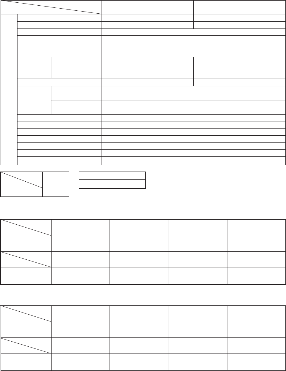
− 141 −
25. SPECIFICATIONS
Voltage and Frequency
Specifications
Motor
SC-380
Model name
Voltage (V)
Rate output (W)
Rate speed (r/min)
Rate torque (N.m)
Model name
Voltage (V)
Speed control
range
Solenoid voltage
Range of rating Voltage
Ambient temperature
Ambient humidity
Storage temperature
Altitude
Weight (kg)
General purpose
automatic thread
trimmer (V)
With sewing machine
shaft (S/min)
With motor shaft
(r/min)
550 W
3,000 r/min
1.76 Nm (0.18 Kgm)
70 to 4,000 (MAX 8,999) S/min
50 to 3,600 r/min
DC 24 V/30 V
±10 %
5 ˚C to 40 ˚C
30 % to 95 %
-25 ˚C to 55 ˚C
Under 1000 m above mean sea level
Motor 8.0 kg/Control Box : 5.5 kg
110 V signal phase
50/60 Hz
XL-554-10Y
100 to 120 V
XC-EJK-10-05
XC-EJK : 100-110/110-120 V
230 V single phase, 3-phase 50/60 Hz
XL-554-20Y, JE type (XL-554-20CE)
200 to 240 V
XC-EJK-20-05
JE type (XC-EJKCE-20-05)
XC-EJK : 200-220/220-240 V
Model
Specification
Lever unit XC-CL-2
XC-EJK Position detector
XC-KE-01PJ
(DC 24 V Setting)
Solenoid
Specifications
Impedance
Solenoid
Specifications
Impedance
OF
(Presser foot lifter output FU)
8 or more
(continuous time rating)
OC
(back stitch output B)
4 or more
(short time rating)
OA
(Thread trimming output T)
4 or more
(short time rating)
O1
(Virtual output1)
4 or more
(short time rating)
OB
(Wiper output W)
4 or more
(short time rating)
O2
(needle cooler output)
4 or more
(short time rating)
OD
(Thread release L)
4 or more
(short time rating)
O3
(TF output TF)
4 or moer
(short time rating)
(DC 30 V Setting)
Solenoid
Specifications
Impedance
Solenoid
Specifications
Impedance
OF
(Presser foot lifter output FU)
10 or more
(continuous time rating)
OC
(back stitch output B)
5 or more
(short time rating)
OA
(Thread trimming output T)
5 or more
(short time rating)
O1
(Virtual output1)
5 or more
(short time rating)
OB
(Wiper output W)
5 or more
(short time rating)
O2
(needle cooler output)
5 or more
(short time rating)
OD
(Thread release L)
5 or more
(short time rating)
O3
(TF output TF)
5 or moer
(short time rating)
Note) 1. In the brackets, it is a factory setting.
2. The continuous time rating of “OF” output is 50 percentage of chopping duty.
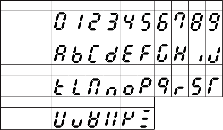
− 142 −
<REFERENCE> TABLE OF DIGITAL DISPLAY
Table of digital display
Numeral 0 1 2 3 4 5 6 7 8 9
Digital display
Numeral A B C D E F G H I J
Digital display
Numeral K L M N O P Q R S T
Digital display
Numeral U V W X Y Z
Digital display

Please do not hesitate to contact our distributors or agents in your area for further information when necessary.
*The description covered in this engineer's manual is subject to change for improvement of the
commodity without notice.
01 · 03 Printed in Japan (E)
R
INTERNATIONAL SALES H.Q.
8-2-1, KOKURYO-CHO,
CHOFU-SHI, TOKYO 182-8655, JAPAN
PHONE : (81)3-3430-4001 to 4005
FAX : (81)3-3430-4909 • 4914 • 4984
TELEX : J22967
Copyright C 1998-2001 JUKI CORPORATION.
All rights reserved throughout the world.
