ACOEM CAC1005000 RADIO FREQUENCY SENSOR User Manual ENG 2AC3Z CAC1005000
ACOEM RADIO FREQUENCY SENSOR ENG 2AC3Z CAC1005000
ACOEM >
Contents
- 1. User Manual Attestation statement - 2AC3Z-CAC1005000.pdf
- 2. User manual ENG - 2AC3Z-CAC1005000.PDF
- 3. User manual FR - 2AC3Z-CAC1005000.pdf
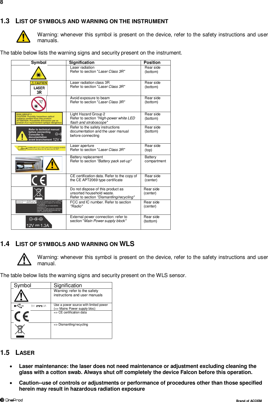
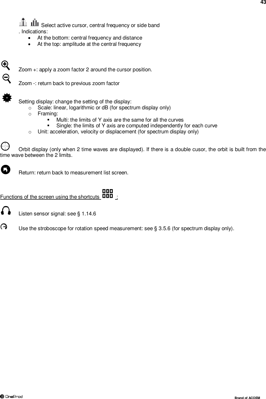
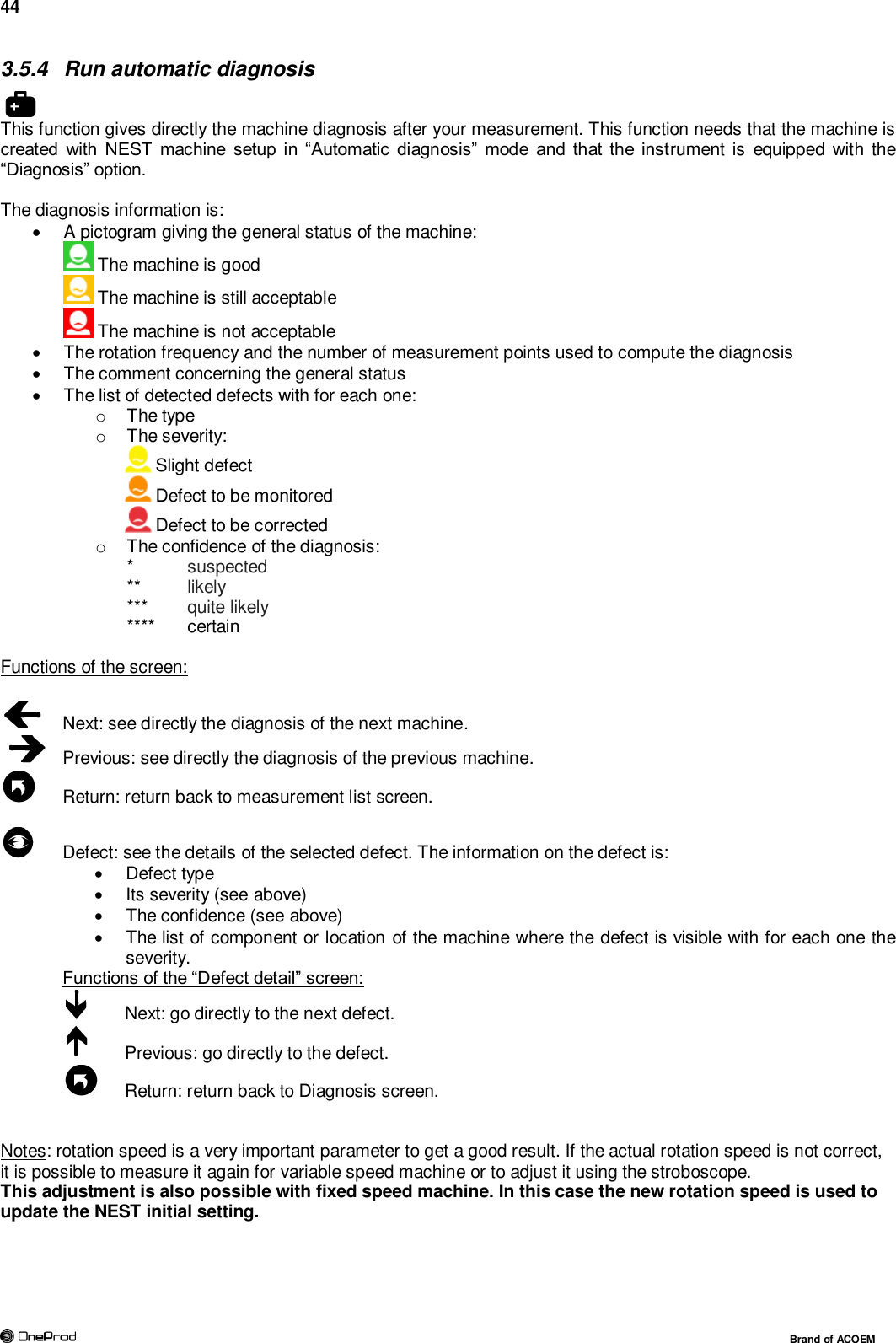
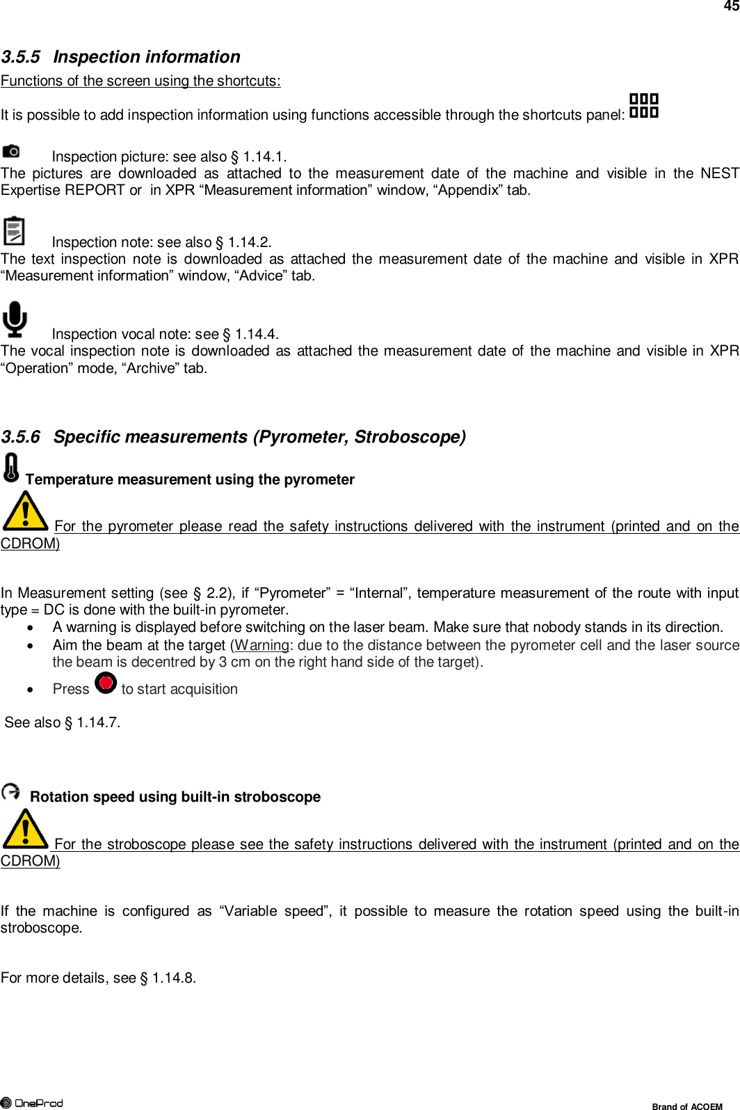
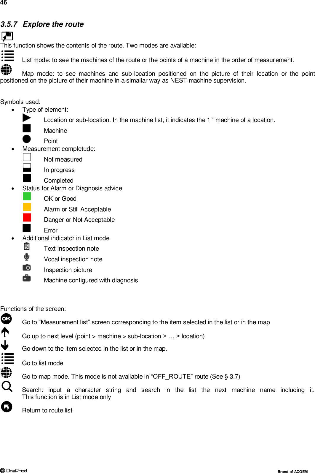
User manual ENG - 2AC3Z-CAC1005000.PDF


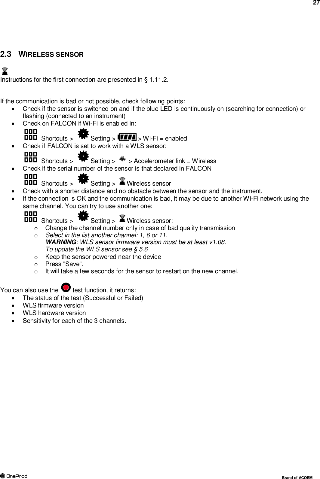
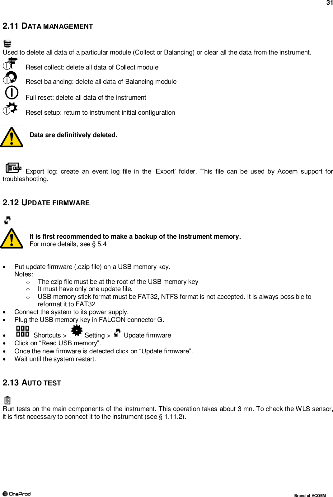
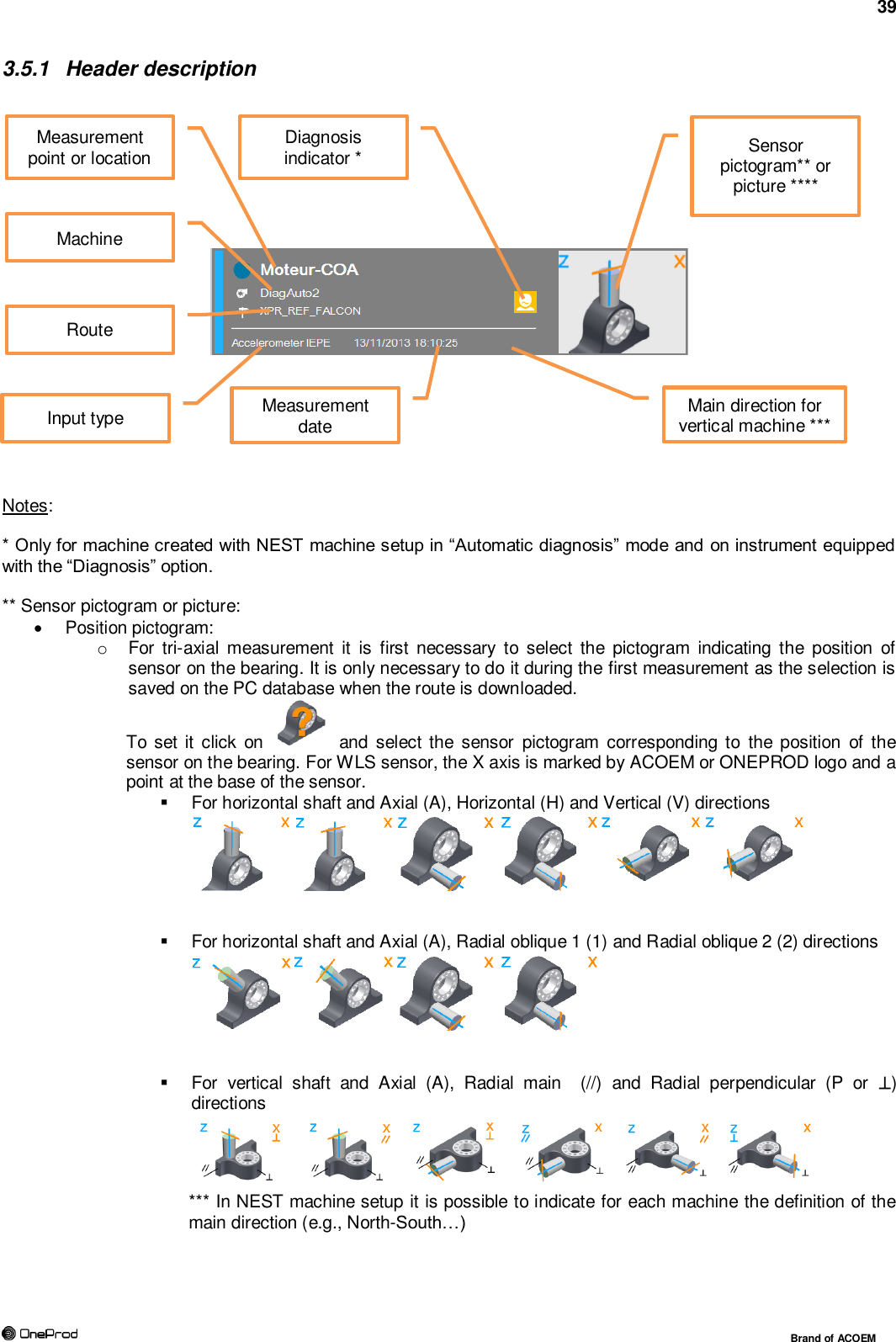
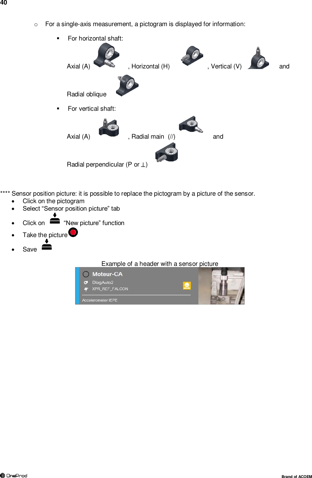
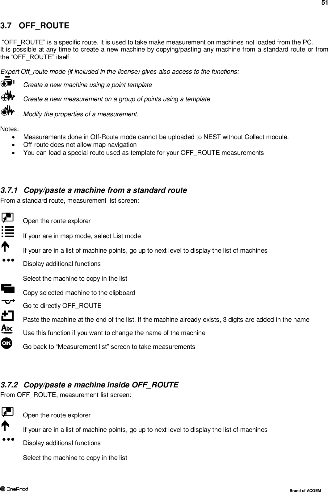
![53 Brand of ACOEM 3.7.4 Create a new measurement on a group of point in Off-route From OFF_ROUTE, measurement list screen: Display additional functions Add a measurement using a template. The template measurement is selected from OFF_ROUTE route or any other routes stored in the instrument. The selection is applied on all the points of the group. Notes: For Accelerometer, Velocimeter, and Other dynamic input types, it is also possible to select if the sensor is power supplied (IEPE) or not (AC). A template route is supplied on the instrument CD (see§ 3.7.6). The function “Save” creates the new measurement. “Cancel” exits with no creation. 3.7.5 Modify a measurement on a group of points in Off-route From OFF_ROUTE, measurement list screen: Display additional functions Modify: modify the properties of selected measurement Notes: If there are several points in the current group with different properties, the modification is done on the base of the setting of the 1st point. In this case a warning is displayed to avoid wrong operations. If measurement is already done, properties can be displayed but cannot be changed. To make a modification you must first reset all the measurements of the group with . The function “Modify” is not accessible for machines with automatic diagnosis. Properties are displayed on 2 or 3 tabs: 3.7.5.1 Tab 1 Input and measurement type: Measurement identification: up to 20 characters. If the name already exists, a re-indexed name is proposed when saving the new measurement. Input type: select the item corresponding to the used sensor type. The list is: o Accelerometer IEPE o Accelerometer AC o Velocimeter IEPE o Velocimeter AC o Displacement AC Note: if the parameter is Relative displacement or Position (Proximity probe) input range is [-24 to 0V], if the parameter is Absolute displacement input range is [-10 to +10V]. o IEPE (other) o AC (other) o DC o Tacho input o Keyboard: manual input using keyboard](https://usermanual.wiki/ACOEM/CAC1005000.User-manual-ENG-2AC3Z-CAC1005000-PDF/User-Guide-2552731-Page-53.png)
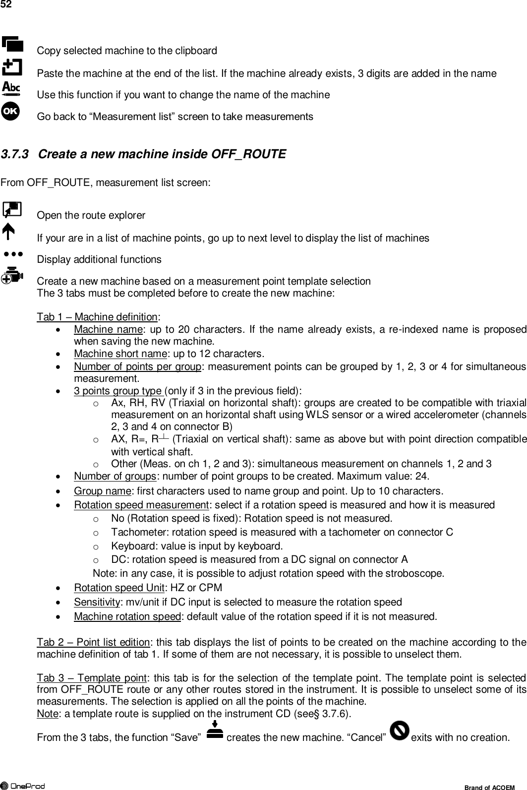
![54 Brand of ACOEM Input unit*: o For accelerometer: g, m/s2 o For velocimeter: in/s, mm/s o For displacement AC: mils, µm o For other input types, the unit is the same as the parameter unit. Sensitivity*: for each point of the group in mV/input unit. * only accessible for the 1st measurement of a group. The values are used for all other measurement of the group. Measurement Type: The selection is either to measure one value: o Overall level o Bearing defect factor (DEF) o Kurtosis o Position … or a signal: o Spectrum. o Envelope o Phased spectrum o Time waveform Notes: the list depends of the selected input type: Input type Measurement type Accel Veloc. Displ. Other DC Keyb. Overall DEF Kurtosis Position Time Spectrum. Envelop Phased spectrum Tabs 2 and 3 depend on the selected measurement type. 0 dB reference: for overall level and spectrum displayed in dB. Measured parameter: the selection depends of the selected input type: Input type Parameter Accelerometer Acceleration, Velocity, Absolute displacement Defect factor, Kurtosis Velocimeter Velocity, Absolute displacement Displacement Relative displacement, Absolute displacement* Position Other Other (to manage other type of parameters) DC Rotation speed, Pressure, flow, temperature, other Keyboard Rotation speed, Pressure, flow, temperature, other * Absolute displacement choice is only available for Overall Level measurement. The default value for spectrum and time wave is Relative displacement. If spectrum and time wave are associated to an Absolute displacement overall level, measurement will be done with input range [-10, 10 V], otherwise the input range is set to [-24, 0 V].](https://usermanual.wiki/ACOEM/CAC1005000.User-manual-ENG-2AC3Z-CAC1005000-PDF/User-Guide-2552731-Page-54.png)