ACR Electronics ACR-AIS-300 Class B Automatic Identification System User Manual Y1 03 0222 Rev T4
ACR Electronics, Inc. Class B Automatic Identification System Y1 03 0222 Rev T4
UserManual.wiki
>
ACR Electronics
>
ACR AIS 300 User Manual
AIS 300 Users Manual
Navigation menu
Upload a User Manual
Namespaces
Wiki Guide
HTML
PDF
Info
Views
User Manual
Discussion / Help
Navigation
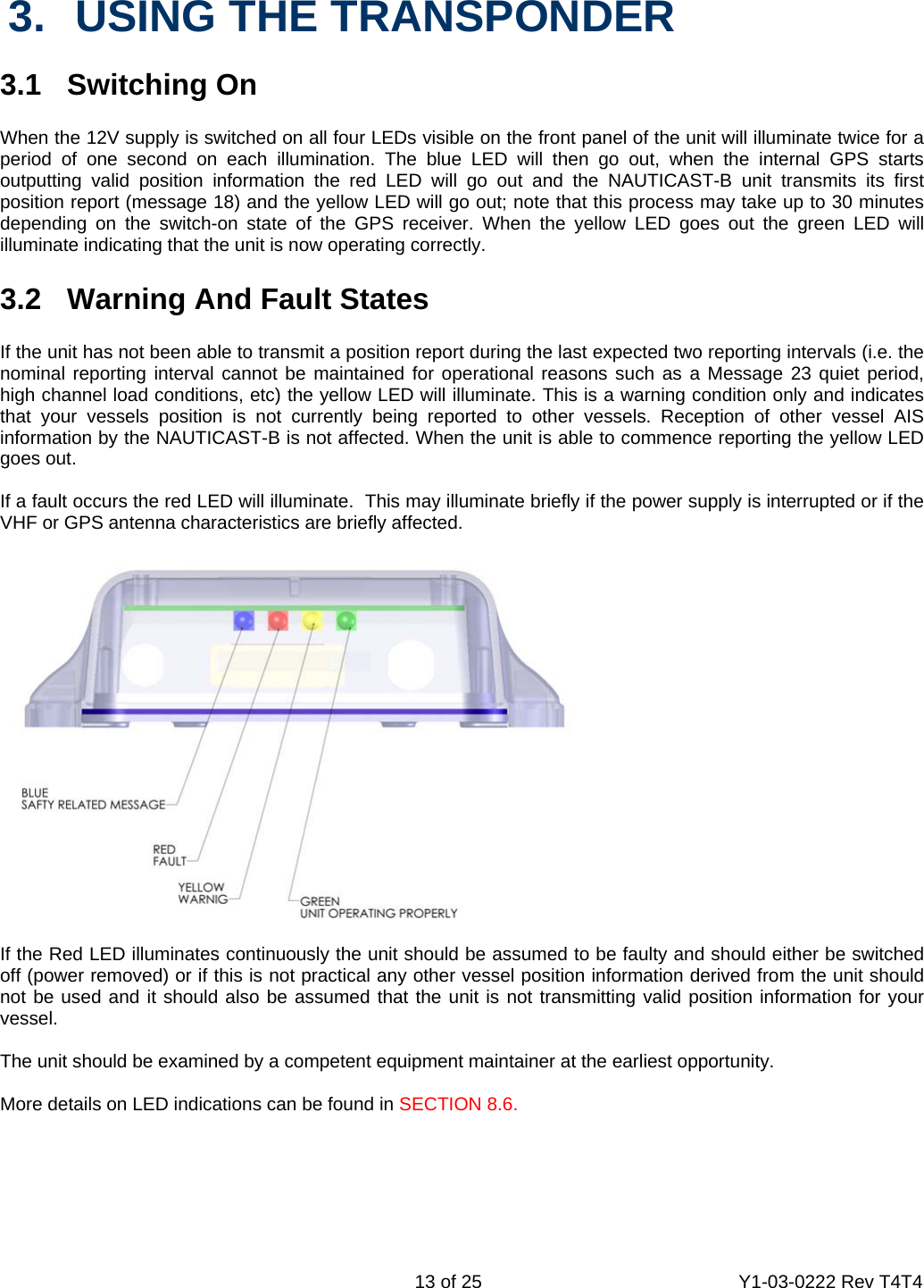
![15 of 25 Y1-03-0222 Rev T4T4 3.6 Led Indicators 3.6.1. Power This is a green LED which indicates, when lit, that power has been connected correctly to the transponder, that the transponder hardware has been configured, that the operating software is present, that the CPU has booted up and the application software is running. 3.6.2 TX Timeout This is a yellow LED which indicates when lit that the CSTDMA transmitter is prevented from transmitting. Reasons for this include the following: The transponder’s internal GPS receiver is not operating or is not yet ready. [1] requires that a class B CSTMA transponder shall not transmit if its internal position sensor is not operating The transponder was unable to transmit an AIS message due to the channel being already occupied, e.g. by transmissions from other AIS transponders 3.6.3 Error This is a red LED which indicates, when lit, one of the following status conditions is possible: Transmitter lockout timer (1 second maximum) has operated GPS is unable to gain lock after 30 minutes VHF antenna VSWR is out of range Power Supply is out of range Background noise level is above the threshold level (-77dBm) 3.6.4 Safety Related Message (SRM) Status This is a blue LED which indicates when lit that the SRM button has been depressed for more than 2 seconds and the pre-set SRM has been sent. If the SRM LED is illuminated it is not possible to send another SRM. An SRM can be sent once a second. The payload within the message 14 transmission is the text string “MAYDAY” by default. 3.6.5 Silent Mode Function (if user configures SRM switch to act as Silent Mode switch) This is a blue LED which indicates when lit that the Silent Mode button has been depressed for more than 2 seconds and the pre-set Silent Mode has been activated. If the blue LED is illuminated you are not transmitting your AIS data to other vessels, your AIS is acting as a receive only device. Depress the Silent Mode button a second time transmit your position data. 3.7 Antennas The NAUTICAST-B unit requires VHF and GPS antennas independent from those in use for other purposes. Please see Appendix A for details of the antennae required. 4. MAINTENANCE WARNING: Unauthorized opening of the NAUTICAST-B system will invalidate the warranty. CAUTION: Avoid using chemical solvents to clean the NAUTICAST-B as some solvents can damage the case material. To clean, wipe down with a damp cloth.](https://usermanual.wiki/ACR-Electronics/ACR-AIS-300/User-Guide-764287-Page-15.png)