ACR Electronics ACR-RLB35 GlobalFix 406 User Manual Y1 03 0157A
ACR Electronics, Inc. GlobalFix 406 Y1 03 0157A
Product Manual

1Y1-03-0157 Rev. T1
PRODUCT
SUPPORT
MANUAL
Y1-03-0157
Rev. T1
GlobalFixTMTM 406
Emergency Position
Indicating Radio Beacon
FCC Type Accepted
Product No. 2742 Cat. I
Product No. 2744 Cat. II
Owner
Vessel
Radio CallSign
ACR Electronics, Inc.
5757 Ravenswood Road
Fort Lauderdale, Fl 33312
+1(954) 981-3333 • Fax +1 (954) 983-5087
http://www.acrelectronics.com
Email: Info@acrelectronics.com

2Y1-03-0157 Rev. T1
* * * WARNING * * *
THIS TRANSMITTER IS AUTHORIZED FOR USE
ONLY DURING SITUATIONS OF GRAVE
AND IMMINENT DANGER
DELIBERATE MISUSE MAY
INCUR A SEVERE PENALTY
Advice to owners of Emergency Position Indicating Radio Beacons (EPIRBs)
Registration of 406 MHz satellite EPIRB with the EPIRB Registration Section of
the national authority* is mandatory because of the global alerting nature of the
system.
The information provided in the Registration Card is used only for rescue pur-
poses.
Fill in the owner registration card immediately upon completion of the sales
transaction. Mail the Registration Card immediately.
If the beacon is to enter service immediately, complete the Registration Card and
fax the information to the national authority. The original card must still be mailed
to the national authority* for hard-copy reference and filing.
If the current owner is transferring the beacon to a new owner, the current owner
is required to inform the national authority* by letter, facsimile or telephone, of the
name and address of the new owner.
The subsequent owner of the beacon is required to provide the national authority*
with the information as shown on the owner Registration Card.
This obligation transfers to all subsequent owners.
*National Authority
The term “national authority” appears throughout this manual. Wherever these
words appear, reference is made to the government body responsible for EPIRB
registration for the country in which the vessel is registered. The addresses for
various national authorities can be found on the Registration Card appropriate for
your vessel.
The national authority in the U.S.A. is NOAA. The NOAA registration telephone
no. is 1-888-212-7283 (toll free).
Note: In the U.S.A. please use the enclosed FCC FORM 506 to modify your
radio station license if necessary. For information on whether you need a
radiostation license, call 1-888-CALLFCC (toll free)
SECTION 1 - THE SYSTEM
23 Y1-03-0157 Rev. T1

22 Y1-03-0157 Rev. T1 3Y1-03-0157 Rev. T1
1.1 GENERAL
1.1.1 This manual provides installation, operation and maintenance in-
structions for the GlobalFix™ 406 Emergency Position Indicating
Radio Beacon, hereinafter referred to as the Beacon. This section
describes the characteristics and details of the Beacon System. The
FCC authorizes the use of 406 MHz Radio Beacons by any ship that
is also equipped with a VHF Ship Station. This will make the 406
MHz Radio Beacon available for use on most U.S. ships and boats.
EPIRB carriage requirements are contained in USCG regulations.
1.2 PURPOSE
1.2.1 The GlobalFix™ 406 Beacon provides distress alerting via radio
transmission on 406 MHz to satellites of the COSPAS-SARSAT
network and to the GEOSAR network that includes GPS latitude and
longitude coordinates.
1.2.2 The message transmitted by the GlobalFix™ 406 is unique for each
EPIRB, which provides identification of the transmitter through
computer access of registration files maintained by the National
Oceanic and Atmospheric Administration or other national authority.
It is the user’s responsibility to fill out and mail the enclosed
registration form to the appropriate agency of the country under
which the vessel is registered. US flagged vessels send the en-
closed NOAA/NESDIS form to NOAA in the stamped envelope
provided. For vessels registered in other countries, the GlobalFix™
406 must be reprogrammed by an ACR authorized programming
facility for the registered country. Remember, if your EPIRB is not
registered, SAR Authorities do not know who you are, what type of
vessel, your homeport, or where to contact anyone who might know
anything about your situation.
1.2.3 Once the GlobalFix™ 406 signal (406 MHz) is relayed through the
COSPAS-SARSAT and/or GEOSAR network alert, Search and Res-
cue (SAR) forces, they can converge on the GPS navigation position.
When the GlobalFix™ 406 is used, SAR authorities can know your
precise location immediately and speed up reaction time. The Glob-
alFix™ 406 on board radio beacon transmitter (121.5 MHz) and
high intensity xenon strobe light aid intermediate and short-range
location.
1.2.4 Product number 2742 GlobalFix™ 406 may be deployed and acti-
vated automatically by the built-in hydrostatic float free release.
4Y1-03-0157 Rev. T1
Once free from the release bracket, the GlobalFix™ 406 will
automatically turn on if the water sensors are wet.
1.2.5 Alternately, the GlobalFix™ 406 can be manually activated by
lifting the thumb switch to a vertical position, sliding it toward
the antenna and pushing back down to the opposite side of the
EPIRB. Activating the beacon in this manner breaks off the
"Activation Indicator Plastic Pin" and allows the switch to
properly seat, showing the " z " symbol (ON).
1.2.6 Self contained long life batteries with a five-year recommended
replacement cycle provide power. See Factory Authorized Ser-
vice Center for replacement (Section 4.0 – Maintenance).
1.2.7 Self-test is initiated by momentarily lifting the thumb switch to
a vertical position and holding it in this position for at least two
seconds and at most 4 seconds. A beep and the simultaneous
lighting of the red LED indicate the initiation of the test. The
buzzer will beep an additional four times as the red LED lights
simultaneously. The green LED will then light, followed by a
flash of the strobe, indicating a successful test. During self-test,
an actual satellite message is transmitted while certain key
performance parameters are measured and recorded. The self-
test message is modified to prevent the satellite from forwarding
an alert message during self-test.
Warning : The following test should never be performed
more than once during the five-year life of the battery pack!
1.2.8 If the thumb switch is held in the vertical position after the
Self-test has finished, the buzzer will beep and the red LED will
light simultaneously. This beep and simultaneous red LED
indicates that the GPS has been turned ON and a live test of the
internal GPS has begun. At this point the thumb switch should
be allowed to return to its normal OFF position. The GPS will
remain ON until good navigation data has been obtained or until
10 minutes has elapsed. If good navigation data has been
obtained, the GPS will be turned OFF and the green LED will
light for 2 to 3 seconds. This navigation data is not saved for
use when the beacon is turned ON. A green LED indication is
proof that the GPS is functioning properly and that the beacon is
in a location or environment where it can receive the necessary
21 Y1-03-0157 Rev. T1
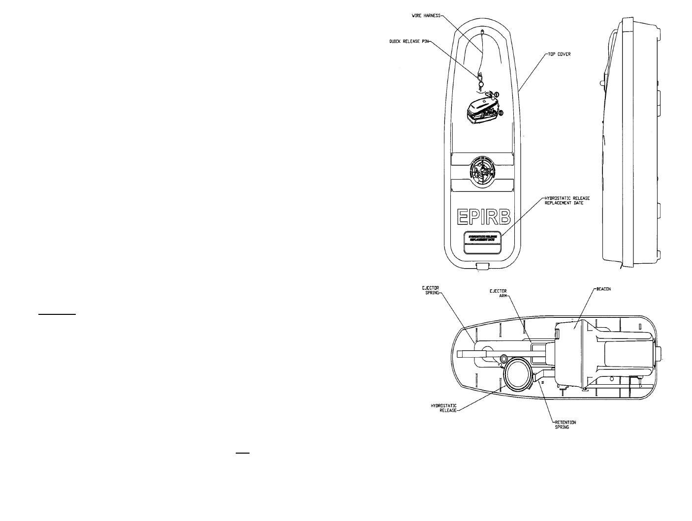
Universal Sea Shelter
Figure 6
20 Y1-03-0157 Rev. T1
ACR GlobalFix™ 406
Figure 5
5Y1-03-0157 Rev. T1
signals from satellites. IF the GPS never gets good navigation
data, the GPS will turn OFF after 10 minutes and there will be
no successful green LED indication. This test should never be
performed more than once during the five-year life of the
battery pack to prevent excessive current drain!
1.2.9 If the thumb switch is accidentally or inadvertently put in the
vertical position (not in the OFF or ON position), the beacon
would still be turned ON and would drain the battery. That this
should happen accidentally or inadvertently is very unlikely.
However, if this should occur, the beacon will sound a beep
once per second and will alternately flash the red and green
LED’s at a rate of one per second until the beacon is turned
OFF. It is important that the beacon be turned OFF immediately
(lowering the thumb switch to the OFF position, thumb switch at
rest in the front position) if this alert is ever obtained.
1.3 SATELLITE DETECTION
1.3.1 The GlobalFix™ 406 transmits an encoded phase modulated
radio signal to the satellite portion of the COSPAS-SARSAT
System. The system was developed and implemented by the
COSPAS-SARSAT Partners (Russian Federation, Canada,
France and the United States).
1.3.2 COSPAS-SARSAT is an international system that uses Russian
Federation and United States low altitude, near-polar orbiting
satellites that assist in detecting and locating activated
121.5/243 MHz EPIRBs and 406 MHz Satellite EPIRBs. The
Russian Federation provides aboard COSMOS navigation
spacecraft COSPAS payloads that are inter-operable with the
SARSAT System. In addition to weather and environmental
sensors, SARSAT payloads, provided by Canada and France,
are carried aboard the United States National Oceanic and
Atmospheric Administration’s (NOAA’s) Advanced TIROS en-
vironmental satellites. (See Figure 1: Satellite Detection)
1.3.3 COSPAS and SARSAT satellites receive distress signals from
satellite EPIRBs transmitting on the frequency of 406.025 or
406.028 MHz. The COSPAS-SARSAT 406 MHz satellite
EPIRB signal consists of a transmission of non-modulated
carrier followed by a digital message format that provides
identification data. The 406 MHz system uses spacecraft-borne
6Y1-03-0157 Rev. T1
equipment to measure and store the Doppler-shifted frequency
along with the satellite EPIRB digital data message and time of
measurement. This information is transmitted in real time to an
earth station called the Local User Terminal (LUT), which may
be within the view of the satellite, as well as being stored for
later transmission to other LUTs. In the real-time mode, the
signal detection is limited to a mutual EPIRB-satellite-LUT
circular visibility area of about 2500 km radius that moves with
the satellite along its track. However, because of the stored-
mode capability at 406 MHz, the need for this mutual EPIRB-
satellite-LUT visibility is not essential, and the system is fully
functional worldwide.
1.3.4 The LUT processes the Doppler-shifted signal and determines
the location of the satellite EPIRB; then the LUT relays the
position of the distress to a Mission Control Center (MCC)
where the distress alert and location information is immediately
forwarded to an appropriate maritime Rescue Coordination
Center (RCC). The RCC dispatches Search and Rescue (SAR)
forces.
1.3.5 The COSPAS-SARSAT System includes 36 LEOSAR LUT
stations, 6 GEOSAR LUT stations and 19 Mission Control
Centers that provide real-time as well as global-mode coverage
for the Northern Hemisphere, while the Southern Hemisphere is
presently served primarily by the global mode. Additional LUTs
and MCCs are planned for installation in the near future both in
the northern and southern hemispheres.
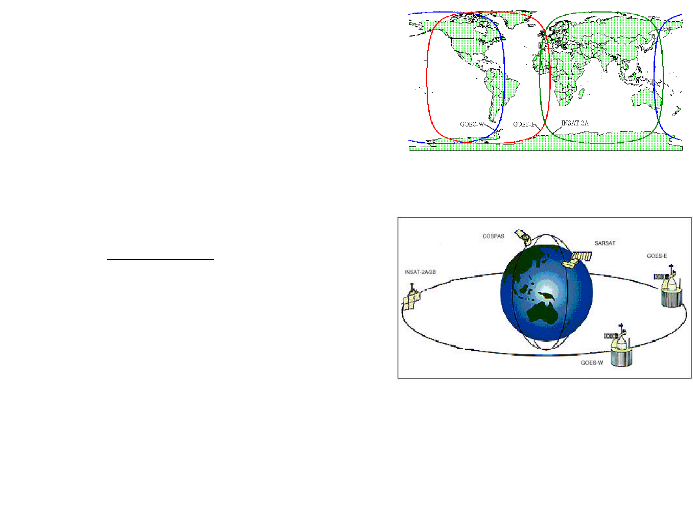
The addition of the GEOSAR Satellite system greatly improves
the reaction time for a SAR event. This satellite system has no
Doppler capabilities at 406 but will relay the distress alert to any
of the LUT stations. When there is GPS data included in the
distress message, SAR authorities instantly know where you are
located. This speeds up the reaction time by not having to wait
for one of the LEOSAR satellite's to come around.
GEOSAR SATELLITE COVERAGE
Figure 1
SAR SATELLITE ORBITS
19 Y1-03-0157 Rev. T1
*** WARNING ***
THIS TRANSMITTER IS AUTHORIZED FOR USE
ONLY DURING SITUATIONS OF GRAVE
AND IMMINENT DANGER
FIGURE 4
18 Y1-03-0157 Rev. T1
number or code which is broadcast on 406 MHz. Registration
provides the Search and Rescue people with important informa-
tion which will speed up the rescue operation and minimize
false alarms.
5.2 To register this EPIRB with NOAA (USA registration only),
simply fill out and mail the provided form in the enclosed
pre-addressed envelope to NOAA or fax the completed form to
NOAA at (301) 457-5406.
5.3 NOAA will supply a Beacon Registration decal which is to be
affixed to the GlobalFix™ 406. The recommended mounting
location is on the front of bottom case above the instruction
label.
6.0 FALSE ALARMS
6.1 Should there be, for any reason, an inadvertent activation or
false alarm, it must be reported to the nearest search and rescue
authorities. The information that should be reported includes the
satellite EPIRB Unique Identifier Number (UIN); date, time,
duration, and cause of activation; and the location at the time of
activation.
6.2 Contact the following to report false alarms (US):
Atlantic Ocean/Gulf of Mexico—
USCG Atlantic Area Command Center
Tel: (212) 668-7055
Pacific Ocean Area—
USCG Pacific Area Command Center
Tel: (510) 437-3700
From any location—
USCG HQ Command Center
Tel: (800) 323-7233
7Y1-03-0157 Rev. T1
Figure 2
1.3.6 Because most of the search and rescue forces presently are not
equipped to home on the 406 MHz Satellite EPIRB signal,
homing must be accomplished at 121.5 MHz.
1.3.7 The GlobalFix™ 406 EPIRB is available in two combinations.
The following product codes define the options available to
meet specific operational requirements:

8Y1-03-0157 Rev. T1
te: All models above conform to Class 1 Requirements
(operations: –40°C to 55° C storage: -50°C to 70°C)
1.4 AUTHORIZATIONS
1.4.1 The GlobalFix™ 406 EPIRB meets the requirements of Federal
Communications Commission (FCC) Part 80 (Product No. 2742,
2744) and GMDSS (Product No. 2742)
1.5 CHARACTERISTICS
1.5.1 The GlobalFix™ 406 EPIRB is a floatable, battery operated unit.
The beacon case, with its external antenna, is waterproof. The
semiconductor circuits are mounted within the case assembly that
also contains the battery power supply. A “Test/On” switch is
installed on top of the beacon, along with a strobe light. The
beacon must be stored in its special mount, free of obstructions
aboard a vessel for automatic float-off. The unit is self-buoyant and
no external floatation devices are required.
1.6 TECHNICAL DATA - GlobalFix™ 406
1.6.1 Applicable Documents
RTCM Standard for 406 MHz Satellite EPIRBs
COSPAS-SARSAT Document C/S T.001 Oct. 99
FCC Part 80 (Model No. RLB-35) and
GMDSS (Product No. 2742)
Prod. No. Model No. Cat. I Cat. II
2742 RLB-35 X
2744 RLB-35 X
17 Y1-03-0157 Rev. T1
4.3 The hydrostatic release unit (HRU) must be replaced by the date
indicated on the float free mounting bracket. The hydrostatic
release can be replaced by removing the Beacon from the
bracket, then sliding the hydrostatic release assembly out of the
keyed opening on the spring and mounting bracket. Insert the
new hydrostatic release assembly, in place by engaging it to the
opening of the ejection spring and case. When servicing the
HRU, ACR strongly recommends replacing the entire hydro-
static assembly, including hydrostatic release, release rod and
all hardware (P/N 9367). Always use original ACR replacement
parts. Use of unauthorized replacement parts may void your
warranty. Place beacon into the mounting bracket, and replace
cover, securing in place with hitch pin going through the hydro-
static release rod.
4.4 The battery (P/N 1096) must be replaced by the date indicated
on the beacon. At each inspection, check the time remaining
until replacement is required.
NOTE: There are no user serviceable items inside the EPIRB.
DO NOT OPEN THE EPIRB UNLESS TO DISABLE IN
CASE OF FAULTY ACTIVATION.
Refer all long life battery replacement and other internal EPIRB
service to a factory authorized service center.
For the nearest location of a factory authorized service center,
call 1-800-432-0227 Ext. 112 (toll free).
4.5 The GlobalFix™ 406 contain lithium batteries which are not
subject to the requirements of the DOT Subchapter C, Haz-
ardous Materials Regulations, because they meet the United
Nations Classification of LiS02 Batteries for Shipment of "Non
– Dangerous".
5.0 REGISTRATION
5.1 It is imperative that this EPIRB be registered with NOAA
(National Oceanic and Atmospheric Administration) in the USA
or with your own national authority.
The EPIRB has been programmed with a unique identification

16 Y1-03-0157 Rev. T1
3.7 INTERNAL GPS
3.7.1 The GlobalFix™ 406 is fitted with an internal Global Position-
ing System receiver that will determine the navigational coordi-
nates, latitude and longitude, of its position on the globe to be
transmitted to the emergency system. When the GlobalFix™
406 is turned ON, the GPS is immediately turned ON and it
immediately begins acquiring data. Initially the red LED, Light
Emitting Diode, flashes once per second to indicate the Global-
Fix™ 406 is turned ON and operating. As soon as the GPS
receiver acquires good navigational data the red LED stops
blinking and the green LED flashes once per second to indicate
that the internal GPS receiver has acquired good navigational
data. Once good navigational data has been obtained the GPS
receiver waits for 20 minutes before looking for new naviga-
tional data again. If for any reason a time period of 4 hours
passes without the GPS receiver being able to update the last
good set of navigational data, the message transmitted by the
GlobalFix™ 406 will revert back to default data. At this point
the green LED will stop blinking and the red LED will flash
once per second. If at any time after this, good navigational
data is obtained, this data will be transmitted, the red LED will
stop blinking and the green LED will flash once per second.
4.0 MAINTENANCE (Check antenna for tightness)
4.1 At least every ninety days, the float free mounting bracket and
GlobalFix™ 406 EPIRB should be inspected for deterioration
and/or buildup that may affect the function of the beacon or
automatic release.
Also carefully inspect the EPIRB case for any visible cracks.
Cracks may admit moisture, which could falsely activate the
beacon or otherwise cause a malfunction. Any cracking ob-
served should be immediately referred to ACR for evaluation,
(1-800-432-0227 Ext. 112)
4.2 Clean the beacon and the mounting bracket to remove residue
buildups. It is recommended that the mounting bracket be
waxed with a high quality marine wax.
9Y1-03-0157 Rev. T1
1.6.2 Specifications
406 MHz Transmitter
Frequency 406.025 MHz
Frequency Stability ±2 parts per billion/100ms
Output Power 5 watts
Digital Message
Format Serialized1
Duration 520 ms
Rate 400 bps
Encoding Biphase L
Modulation ±1.1 radians peak
1 Leaves ACR with Serialized U.S. code but can be reprogrammed at a
Service center to Maritime MMSI.
121.5 MHz Transmitter
Frequency 121.5 MHz
Frequency Tolerance ±50 ppm
Output Power 25 mW PEP
Modulation
Type AM (3K20A3X)
Sweep Range 400 to 1200 Hz
Sweep Rate 3 Hz
Duty Cycle 37.5%
Antenna
Frequency 406.025 & 121.500 MHz
Polarization Vertical
VSWR Less than 1.5/1
Xenon Strobe
Light Color White
Output Power 0.75 effective candela
Flash Rate 20—30 per minute
General/Environmental
Battery Life
Operating 48 hours minimum
Replacement Interval 5 years
Size
EPIRB less Antenna 9.0" (22.86 cm)
Antenna 7.5" (19.05 cm)
10 Y1-03-0157 Rev. T1
Material, EPIRB High impact and UV resistant
plastic
Color Yellow
Weight 2.1 lbs.
Temperature Range
Operating Class I -40°C to +55°C
Stowage Class I -50°C to +70°C
Mounting Case (Product No. 2742)
Construction White High Impact and UV resistant
plastic
Size 6.5" x 17.1" (16.51 cm x 43.4 cm)
Release System Hydrostatic with manual override
Hydrostatic Release Kits
No. 9367 GlobalFix™ 406
Optional Mounting Brackets are available for Product No. 2742.
Construction White High Impact and UV resistant
plastic
Size 5.3" x 6.9" (13.5 cm x 17.5 cm)
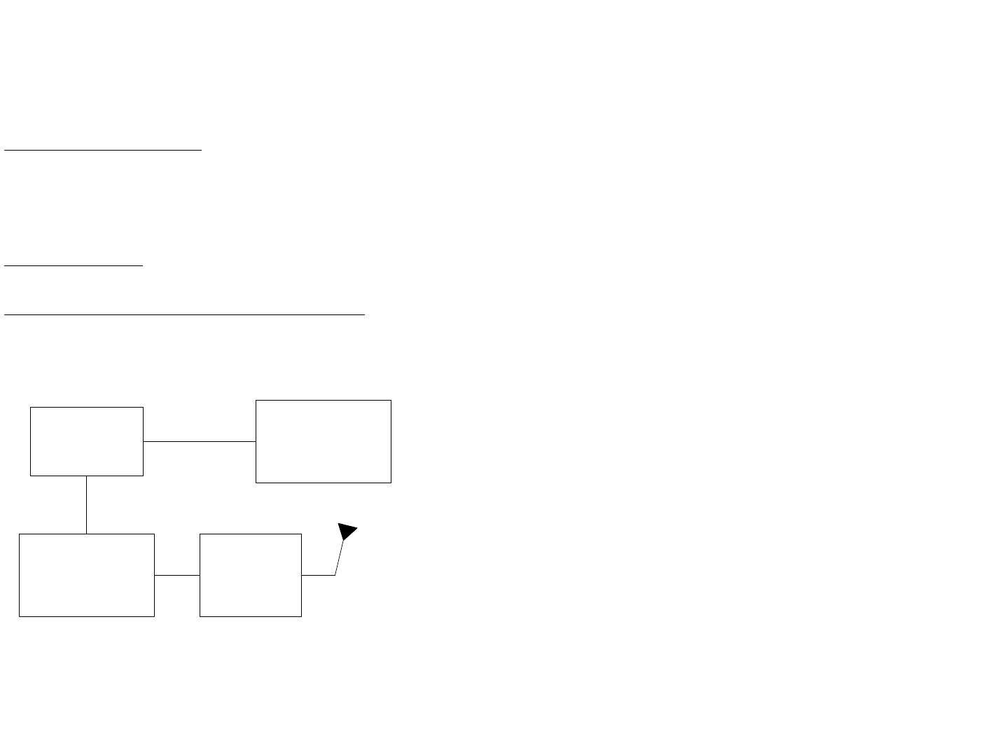
E
PIRB BLOCK DIAGRAM
FIGURE 3
USER /
PROGRAMMING
INTERFACE
MCP
406 / 121.5 MHz RF
AMPLIFIER
15 Y1-03-0157 Rev. T1
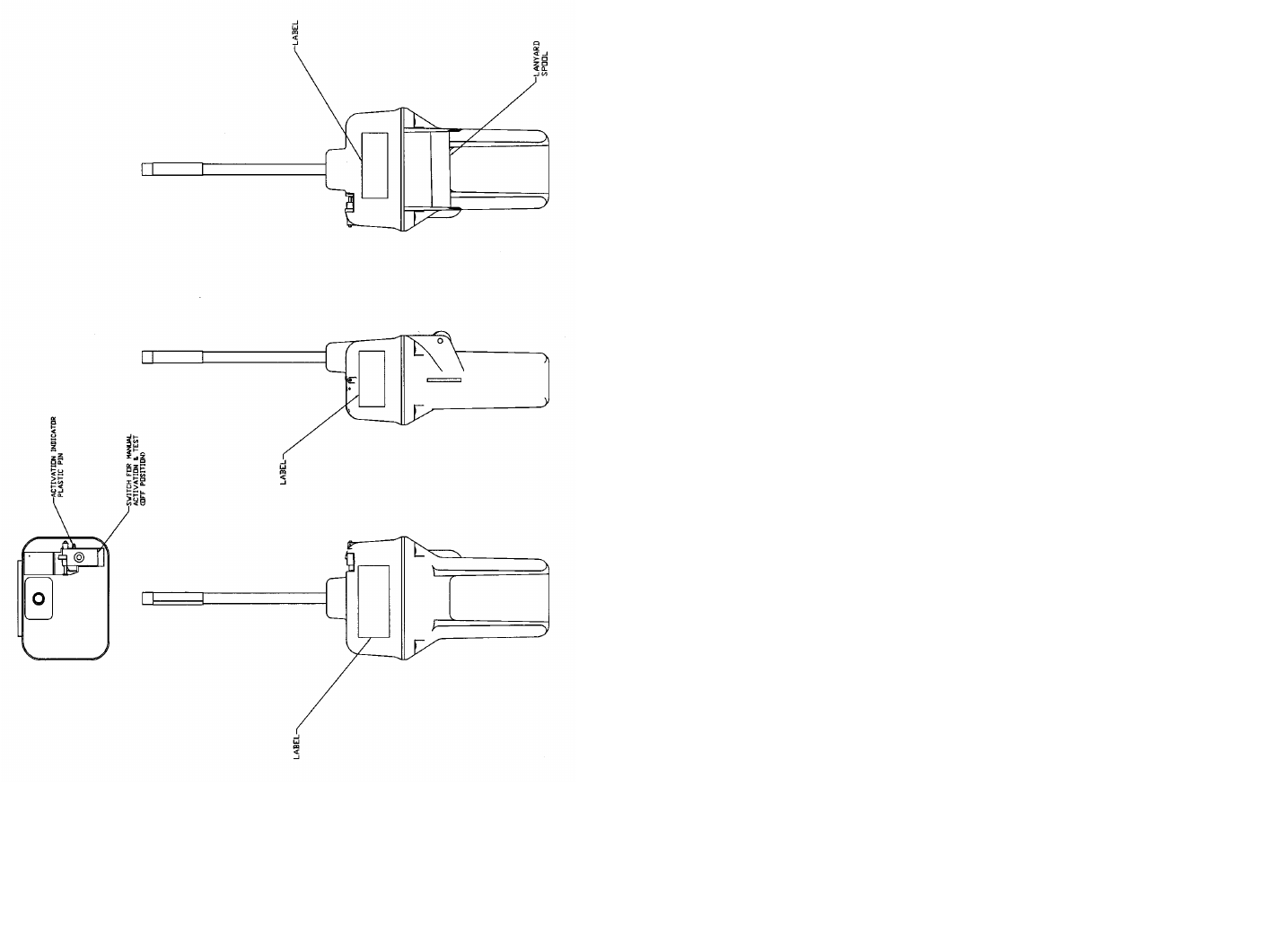
1) Returning the thumb switch to the original OFF position.
If automatically activated:
1) Removing the beacon from the water. The beacon normally takes
up to 12 seconds to deactivate, or
2) Placing the beacon back into the release bracket.
3.5.2 If the beacon continues to operate after it has been deactivated,
remove the four screws holding the unit together and unplug the
battery to disable the unit. Return it to a service center for repair.
3.6 TEST
3.6.1 The GlobalFix™ 406 can be tested in or out of the release bracket.
A Self Test is initiated by lifting the thumb switch to a vertical
position and holding it in this position for at least two seconds. The
initiation of the test is indicated by a beep and the simultaneous
lighting of the red LED.
The sequence of tests is:
1. Check Data Integrity...................Beep and lights up red LED if passed
.....................................................Stop if failed
2. Check 406 MHz Synthesizer ......Beep and lights up red LED if passed
.....................................................Stop if failed
3. Check RF Power/Battery............Beep and lights up red LED if passed
.....................................................Stop if failed
4. Check internal GPS ....................Beep and lights up red LED if passed
.....................................................Stop if failed
5. Turn on green LED to indicate Successful Test.
6. Flash Strobe Light to test Strobe.
If all of the above occurs, the test has been successful.
NOTE: The homing beacon at 121.5 MHz is inhibited during self test.
3.6.2 It is strongly recommended to test the GlobalFix™ 406 on a Monthly
basis.

14 Y1-03-0157 Rev. T1
3.2 AUTOMATIC DEPLOYMENT & DEACTIVATION
(Product No. 2742 only)
3.2.1 Automatic deployment and activation occurs when the vessel
sinks and a hydrostatic release device frees the beacon from the
bracket allowing it to float to the surface. Built-in sensors detect
that the beacon is no longer in its bracket and is in water. This
condition will automatically activate the beacon.
Note: Transmissions of the 121.5 MHz and 406 MHz signal
will not occur until 50 seconds after activation.
3.3 MANUAL DEPLOYMENT & ACTIVATION
3.3.1 The GlobalFix™ 406 can be manually deployed by removing
the retaining pin, removing the cover, then removing the beacon
from the bracket. Once removed, the beacon can be activated by
being placed in water or by lifting the thumb switch towards the
antenna and placing the thumb switch back down on the oppo-
site side of the EPIRB. Activating the beacon in this manner
breaks off the Activation Indicator Plastic Pin and exposes the
"ON" symbol " z " on the thumb switch indicating that the
beacon is turned "ON".
Note: Some countries fine vessel owners for causing false
alarms. The permanent breakage of the Activation Indicator
Plastic Pin is a positive indication of a manual activation.
3.4 MANUAL ACTIVATION WITHOUT DEPLOYMENT
3.4.1 The GlobalFix™ 406 can be activated while still in its bracket
by placing the thumb switch in the ON position. Activation by
this method overrides all sensors and turns the beacon “ON”.
The caution note above still applies.
3.5 DEACTIVATION
3.5.1 The GlobalFix™ 406 can be deactivated by:
If manually activated:
11 Y1-03-0157 Rev. T1
SECTION 2 - INSTALLATION (Attach antenna tightly onto unit)
2.1 MOUNTING LOCATION (Product No 2742)
2.1.1 The GlobalFix™ 406 float-off mounting bracket should be
mounted securely to a vertical or horizontal surface (the mount
has predrilled holes for attachment to a flat surface) where there
are no overhead obstructions. Location aboard a vessel must be
chosen to allow the EPIRB to float free of sinking craft and as
high as possible especially on small vessels. This will help
ensure operation of the hydrostatic release unit in the event the
vessel capsizes without sinking.
2.1.2 The location selected must be sufficiently rigid to support the
weight of the total installation and at the same time consider
vibration, exposure to the elements, exposure to surrounding
hazards such as equipment movement, doors being opened,
accidental covering, personnel traffic, etc., and yet be readily
accessible at all times for the emergency use for which the
beacon is intended.
2.1.3 Also to be considered in selecting a location for installation is
the harmful effect that certain corrosive vapors might have on
the beacon. Under no circumstances should a location be se-
lected for installation where the beacon would be jeopardized
by any foreign articles being temporarily or permanently posi-
tioned during “at sea” or “in port” activities.
CAUTION: Care must be taken to prevent any lanyard, line, or
other emergency equipment that may be attached to the beacon
from becoming entangled or fouled which could prevent the
beacon from being removed in an emergency.
2.1.4 The GlobalFix™ 406 float-off mounting bracket should be
securely attached to the vessel. The use of #10 stainless steel
hardware is recommended.
2.1.5 Do not mount the GlobalFix™ 406 in the vicinity (2 meters) of
strong magnetic (such as loud speakers) or electric (such as
radar or high power radio transmitter) fields.

12 Y1-03-0157 Rev. T1
2.1.6 Consideration should be given to mounting the GlobalFix™
406 in a vertical (antenna upward position). In certain circum-
stances, such as medical emergencies or disabled vessels, man-
ual activation of the EPIRB for location and homing purposes is
sometimes requested. Mounting in this orientation provides the
best homing signal.
2.2 VISUAL INSPECTION
2.2.1 Visually inspect the area surrounding the mounting bracket
installation site for hidden hazards, obstacles, etc., that may
have been overlooked during selection. If there is any doubt as
to the ready accessibility to the beacon at all times or if any
condition may appear to be questionable, make complete and
thorough investigation before making final approval of the
installation.
2.3 HYDROSTATIC RELEASE DATING INSTRUCTION
2.3.1 The label on the hydrostatic release mechanism inside of the
bracket and the replacement date label on the outside of the
bracket MUST be dated with the date of expiration at time of
installation according to coastal marine authority regulations.
To record the expiration date on the hydrostatic release mecha-
nism, remove the perforated dates of the label to indicate the
month and year two years from date of installation. Write the
date of expiration with an indelible marker on the label appear-
ing on the outside cover.
SECTION 3 - OPERATION
3.1 GENERAL
3.1.1 The GlobalFix™ 406 Beacon Model 2742 is designed to be
automatically deployed and activated. The GlobalFix™ 406
may also be hand held on the deck of vessels, or floated in water
and attached to a raft or life vest with the lanyard provided. The
GlobalFix™ 406 is designed to operate best while floating in
water. Hand held operation should be avoided when possible.
13 Y1-03-0157 Rev. T1
Do not operate inside liferaft or under any similar cover or
canopy.
3.1.2 The GlobalFix™ 406 Beacon can be deployed and activated
manually.
3.1.3 Because many users failed to properly place earlier generation
beacons in the “ARMED” or “READY” positions when in-
stalling them in their brackets, U.S. and International specifica-
tions require the elimination of the “OFF” switch position and
the inclusion of sensors to automatically activate the beacon
under specific conditions.
The GlobalFix™ 406 is equipped with sensors to detect when
it is no longer in its bracket (a deployment condition) and other
sensors to determine if it's in water.
Two conditions must be satisfied for the GlobalFix™ 406 to
automatically activate:
1) It must be out of its bracket,
2) It must be in the water,
Note: Either condition by itself will not activate the beacon.
3.1.4 The GlobalFix™ 406 is designed to allow the user to perform
periodic testing while EPIRB is in the release bracket to assure
a functioning beacon.
3.1.5 Place the GlobalFix™ 406 Product No. 2742 into the release
bracket with the coiled lanyard inward. The beacon should now
be firmly held in the release bracket and ready for automatic
deployment.