ACR Electronics ACR-RLB36 RLB-36 GlobalFix iPro User Manual
ACR Electronics, Inc. RLB-36 GlobalFix iPro Users Manual
UserManual.wiki
>
ACR Electronics
>
ACR RLB36 User Manual
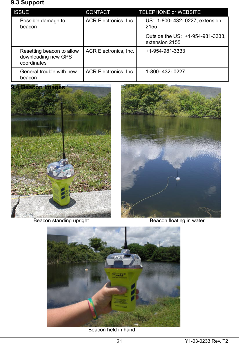
Users Manual
Navigation menu
Upload a User Manual
Namespaces
Wiki Guide
HTML
PDF
Info
Views
User Manual
Discussion / Help
Navigation