ACR Electronics ACR-RLB36 RLB-36 GlobalFix iPro User Manual
ACR Electronics, Inc. RLB-36 GlobalFix iPro Users Manual
Users Manual

Product Support Manual
ACR Electronics, Inc.
5757 Ravenswood Road
Fort Lauderdale, FL 33312
Tel : +1(954) 981-3333
Fax: +1 (954) 983-5087
www.acrelectronics.com
Email: info@acrelectronics.com
EPIRB
Emergency Position Indicating Radio Beacon
RLB-36
Y1-03-0233 Rev. T2

2
* * * WARNING * * *
THIS TRANSMITTER IS AUTHORIZED FOR USE
ONLY DURING SITUATIONS OF GRAVE
AND IMMINENT DANGER
DELIBERATE MISUSE MAY INCUR A SEVERE PENALTY
Magnet Safe Distance
1m (3.3 ft)
Keep this beacon a safe distance
away from all magnetic sources
Stereo Speaker Safe Distance
1m (3.3 ft)
Keep this beacon a safe distance away
from all stereo speakers
IF YOU HAVE ANY TROUBLE WITH
YOUR NEW 406 BEACON, DO NOT RETURN
IT TO THE STORE!
CALL ACR ELECTRONICS AT
+1 (800) 432-0227. WE WILL HELP YOU
RESOLVE ANY PROBLEMS YOU MAY BE
EXPERIENCING. MANY QUESTIONS CAN BE
ANSWERED OVER THE PHONE.
LIMITED WARRANTY
This product is warranted against factory defect in material and workmanship for a period of
ve years from date of purchase or receipt as a gift. During the warranty period ACR Elec-
tronics, Inc. will repair or, at its option, replace at no cost to you for labor, materials or return
transportation, provided you obtain a Return Authorization from ACR Electronics, Inc., 5757
Ravenswood Road, Ft. Lauderdale, Fl. 33312-6645. To obtain a Return Authorization, call
our Customer Service Department at (800) 432-0227. This warranty does not apply if the
product has been damaged by accident or misuse, or as a result of service or modication
by other than the factory. Except as otherwise expressly stated, the COMPANY MAKES
NO REPRESENTATION OR WARRANTY OF ANY KIND, EXPRESS OR IMPLIED, AS TO
MERCHANTABILITY, FITNESS FOR A PARTICULAR PURPOSE, OR ANY OTHER MAT-
TER WITH RESPECT TO THIS PRODUCT. The Company shall not be liable for, conse-
quential or special damages.
In order to place the warranty in effect, the accompanying registration card must be returned
to us within ten days of purchase.

3Y1-03-0233 Rev. T2
TABLE OF CONTENTS
SECTION 1 – FOREWORD AND PRODUCT FEATURES 4
SECTION 2 – REGISTRATION OF 406 MHZ BEACONS 5
2.1 Registration importance 5
2.2 Where to register 5
2.3 Registration in the United States 5
2.4 Leisure vessels in the United States 6
2.5 Commercial vessels in the United States 6
2.6 Do I need a radio station license? 6
2.7 Commercial vessels world wide 6
2.8 Registration outside the United States 6
2.9 Change of ownership or contact information 6
2.10 Lost or stolen EPIRBs 7
SECTION 3 – FALSE ALARMS 7
3.1 Prevention of false alarms 7
3.2 Reporting of false alarms 7
SECTION 4 – INSTALLATION 8
4.1 Mounting location 8
4.2 Visual inspection 8
4.3 Hydrostatic release unit (HRU) catagoy 1 beacon 8
SECTION 5 – ACTIVATION AND DEPLOYMENT 9
5.1 Bracketconguration 9
5.2 Category I & 2 bracket dimensions 10
5.3 Congurationoverview 11
5.4 Automatic deployment and activation - Category I Beacons 12
5.5 Manual deployment and activation 12
5.6 Manual activation without deployment 13
5.7 Deactivation 13
SECTION - 6 INTERNAL AND EXTERNAL GPS 13
6.1 Self testing the beacon 13
6.2 GPS acquisition with the external GPS 14
6.3 Using the external GPS interface 14
6.4 Testing the external GPS interface 14
6.5 Updating the external GPS position data 14
6.6 Internal GPS navigation system 15
6.7 Internal GPS Testing 15
6.8LEDindicationofGPSx 16
6.9 OLED display 16
SECTION 7 – CARE AND MAINTENANCE 16
7.1 Routine maintenance 16
7.2 Battery replacement 16
7.3 Shore based maintenance for SOLAS Vessels 17
7.4 Annual testing for SOLAS vessels, IMO MSC/Circ. 1040 17
SECTION 8 – THE SEARCH AND RESCUE SYSTEM 17
8.1 General overview 17
8.2 Satellite detection 17
8.3 Global Positioning System (GPS) 18
SECTION 9 – TECHNICAL INFORMATION 19
9.1 Type approvals and standards 19
9.2Specications 19
9.3 Support 21
9.4 Beacon Images 21
4
SECTION 1 – FOREWORD AND PRODUCT FEATURES
Thank you for purchasing from ACR Electronics, Inc. We design, manufacture and distribute
quality products knowing they are used to save lives. Many of our products are required
to be tested and approved by regulatory bodies worldwide. We believe in going beyond
those specications to insure our products work when needed in real world conditions. With
proper care and maintenance your ACR product will last for years. It is important that you
thoroughly read this product support manual to understand the proper care and use of your
ACR product.
ACR is proud to be certied to ISO 9001: 2000, the International Standard for Quality.
This manual provides installation, operation and maintenance instructions for the RLB-36
EPIRB, hereinafter referred to as the beacon. This manual also describes the characteris-
tics and details of the beacon system. In the USA, the FCC authorizes the use of 406 MHz
Radio beacon by any ship that is also equipped with a VHF ship station. This will make the
406 MHz radio beacon available for use on most U.S. ships and boats. Commercial EPIRB
carriage requirements are contained in IMO and/or USCG regulations.
Product Model
Number
Product
Number
Category Class GPS
Interface
GlobalFix™ iPro RLB-36 xxxx 1 2 Internal and external
GlobalFix™ iPro RLB-36 xxxx 2 2 Internal and external
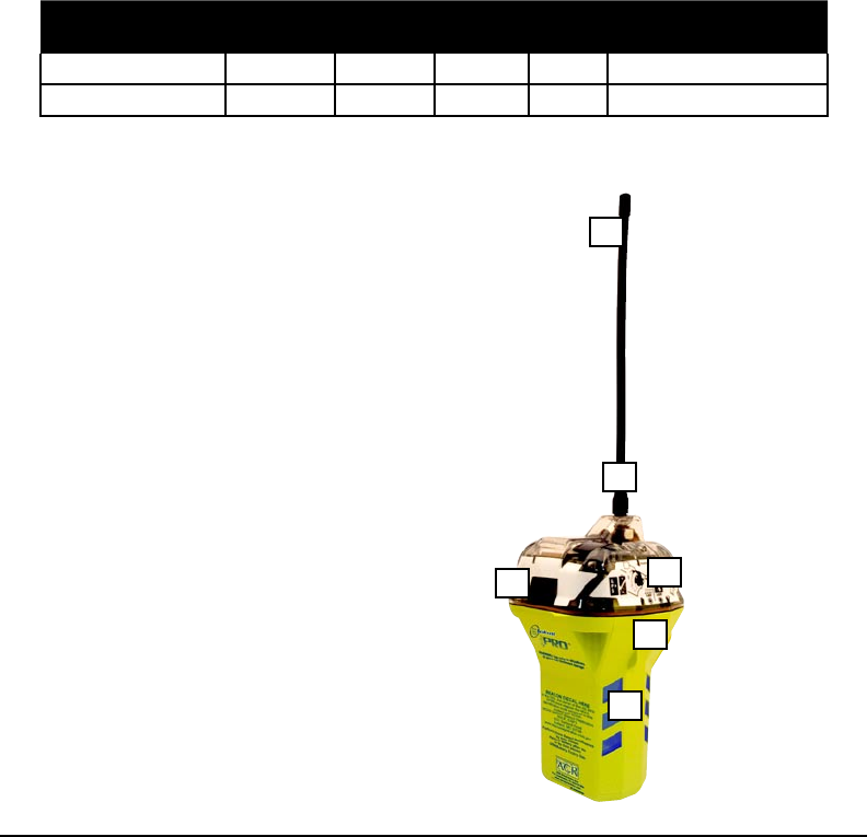
1
2
34
5
6
Product Features
1. Sturdy antenna
2. Ultrabright strobe can be seen for over 2 miles
3. Secondary graphical OLED display unit
4. Reective tape exceeds RTCM specications
5. HIghly visible ACR-truse™ case is durable and
withstands the harshest of environments
6. Grips provide ease when holding the beacon
while wet.
Product Features
Figure 1

5Y1-03-0233 Rev. T2
SECTION 2 – REGISTRATION OF 406 MHZ BEACONS
2.1 Registration importance
It is mandatory that the owner of this 406 MHz beacon register it with the national authority.*
All 406 MHz beacons transmit a Unique Identier Number (UIN) when activated. This UIN is
programmed in the beacon based on the country in which the beacon was purchased. Reg-
istration provides the Search and Rescue (SAR) forces with up to date emergency contact
information, which will speed up the launch of a rescue operation. The national authorities
NOAA SARSAT Beacon Registration
NSOF, E/SP3
4231 Suitland Road
Suitland, MD 20746
For Faster Service, Register Online!
In the United States:
www.beaconregistration.noaa.gov
use the information to verify if an actual emergency exists. Valuable search and rescue
resources are wasted every year responding to false alarms. SAR forces will know who
you are, what type of vessel you have, your homeport, and who to contact that might know
of your current situation ONLY if your beacon has been properly registered. This will help
expedite the launch of a rescue operation. All 406 MHz beacons are required to have their
registration updated every two years.
*The national authority is the governmental body responsible for EPIRB registration data-
base administration for the country for which the EPIRB is programmed.
2.2 Where to register
The owner of a 406 MHz beacon (EPIRB) should register it with the national authority for
which the beacon was programmed (typically the country where purchased), regardless of
where they do their boating. However, the beacon must be reprogrammed if the boat or its
owner moves or sails under a different national authority than the one for which the beacon
was previously programmed. Each beacon is programmed with a Unique Identication Num-
ber (UIN) for the country that the unit is shipped to, and will only be accepted for registration
in that country. To verify the country for which a beacon is programmed, see the label with
the UIN on the side of the unit. Units that do not have a country specied on the UIN label
are programmed for the United States.
2.3 Registration in the United States
It is the owner’s responsibility to register 406 MHz beacons that are programmed for and
purchased in the United States. The national authority that accepts registrations in the Unit-
ed States is the National Oceanic and Atmospheric Administration (NOAA). The fastest and
easiest way to register your beacon with NOAA is to use the online registration database at
www.beaconregistration.noaa.gov. If internet is not accessible then the owner should com-
plete the enclosed registration form (Do not confuse this with the ACR Electronics warranty
card) and mail with the pre-addressed, postage paid envelope to:
The information provided on the registration form is used only for rescue purposes. Com-
plete and send the registration immediately! Registration can be expedited by registering
online or by faxing the registration form to Fax # (301) 817-4565. If the beacon is going to be
placed into immediate service, register online or by fax.
All registration forms will be entered in the 406 MHz beacon registration database within 48
hours of receipt. A conrmation letter, a copy of the actual registration and a proof-of-reg-
istration decal will be mailed to you within two weeks. When you receive these documents,
please check the information carefully and afx the decal to your beacon in the area marked
“BEACON DECAL HERE.” If you do not receive conrmation back from NOAA, call toll free
1-888-212-7283 for assistance.

6
2.4 Leisure vessels in the United States
In the United States, leisure vessels are sometimes required to have a radio station license.
Leisure vessels that are required to have a radio station license are required to modify that
license when an EPIRB is added to the vessel. For information on whether you need a radio
station license, see section 2.6 (below).
2.5 Commercial vessels in the United States
In the United States, commercial vessels that are required to have a radio station license
are required to modify that license when an EPIRB is added to the vessel. For information
on whether you need a radio station license, see section 2.6 (below).
2.6 Do I need a radio station license?
The information in this section is provided for informational purposes only. Always check the
FCC’s website at http://wireless.fcc.gov/services/index.htm?job=licensing&id=ship_stations
or call toll-free 1-888-CALLFCC (225-5322) for the latest information.
You do not need a license to operate a marine VHF radio, radar, or EPIRBs aboard voluntary
ships operating domestically. The term “voluntary ships” refers to ships that are not required
by law to carry a radio. Generally, this term applies to recreation or pleasure craft. The term
“voluntary ships” does not apply to the following:
1. Cargo ships over 300 gross tons navigating in the open sea;
2. Ships certied by the U.S. Coast Guard to carry more than 6 passengers for hire in the
open sea or tidewaters of the U.S.;
3. Power driven ships over 20 meters in length on navigable waterways;
4. Ships of more than 100 gross tons certied by the U.S. Coast Guard to carry at least
one passenger on navigable waterways;
5. Tow boats of more than 7.8 meters in length on navigable waterways; and,
6. Uninspected commercial shing industry vessels required to carry a VHF radio.
7. Ships required to carry an Automatic Identication System (AIS) transceiver by the
U.S. Coast Guard regulations enacted pursuant to the Maritime Transportation Secu-
rity Act of 2000.
Ships are considered as operating domestically when they do not travel to foreign ports or
do not transmit radio communications to foreign stations. Sailing in international waters is
permitted, so long as the previous conditions are met. If you travel to a foreign port (e.g.,
Canada, Mexico, Bahamas, British Virgin Islands), a license is required. Additionally, if you
travel to a foreign port, you are required to have an operator permit.
2.7 Commercial vessels world wide
406 MHz beacons that are carried on commercial vessels world wide should be registered
with the country where the vessel is agged regardless of where the vessel operates. When
a commercial vessel acquires a 406 MHz beacon from outside of its home country, the bea-
con should be reprogrammed for the home country and registered there.
2.8 Registration outside the United States
In countries other than the United States, 406 MHz beacons are registered with that coun-
try’s national authority at the time of purchase. The sales agent should assist in lling out
the forms and sending to that country’s national authority. To verify that the unit is properly
programmed for that country, view the UIN label on the side of the unit. In the event that
the beacon is not programmed for the country it has been purchased in, the sales agent, (if
properly equipped) can reprogram the unit for that country.
2.9 Change of ownership or contact information
It is the owner’s responsibility to advise the national authority of any change in the informa-
tion on the registration form. If the current owner of the beacon is transferring the beacon
to a new owner, the current owner is required to inform the national authority by using
their online database or by letter, fax or telephone, of the name and address of the new

7Y1-03-0233 Rev. T2
owner. The new owner of the beacon is required to provide the national authority with all
of the information requested on the registration form. This obligation transfers to all subse-
quent owners. Registration forms for the United States are available from NOAA by calling
1 (888) 212-7283 or by visiting the ACR website at www.acrelectronics.com.
2.10 Lost or stolen EPIRBs
Inform NOAA immediately at 1-888-212-SAVE (7283), or your national authority, if your
EPIRB has been lost or stolen. They will update your EPIRB registration information with the
appropriate information.
Stolen EPIRBs - Things That You Need To Do:
• Report to your local authorities that the EPIRB has been stolen.
• Contact NOAA at 1-888-212-SAVE (7283), or your national authority, with the following
information so your EPIRB registration information can be updated with the appropri-
ate remarks: Police Department Name, Phone Number, and Case Number
If your EPIRB were to be activated, the information you provided will be forwarded to the
appropriate search and rescue authorities who will ensure that your EPIRB gets back to
you. If someone attempts to register an EPIRB reported as stolen, NOAA or your national
authority will notify the appropriate police department. Visit www.cospas-sarsat.org for more
detailed information.
SECTION 3 – FALSE ALARMS
3.1 Prevention of false alarms
An ACR 406 MHz EPIRB can be activated in an emergency by two different methods.
Whether you have a Category I or II, these methods are the same.
1. When the beacon is out of its bracket and in the water, the unit will start transmitting.
2. When the switch is moved to the “ON” position, in or out of the bracket, the unit will
start transmitting.
There are a few precautions that should be taken to prevent false alarms.
• Do not mount or transport beacon within 3.3 ft/1 m of a magnetic source.
• Do not store beacon outside of its bracket if it can get wet.
• Do not mount EPIRB backwards in its bracket (lanyard roll must not be visible).
• Do not clean beacon with a water hose and brush while out of its bracket.
3.2 Reporting of false alarms
Should there be, for any reason, an inadvertent activation or false alarm, it must be reported
to the nearest search and rescue authorities. The information that should be reported in-
cludes the EPIRB 15-digit Unique Identier Number (UIN), date, time, duration and cause of
activation, as well as location of beacon at the time of activation.
To Report False Alarms in the United States Contact any of the Following:
Atlantic Ocean / Gulf of Mexico
USCG Atlantic Area Command Center Tel: (757) 398-6390
Pacic Ocean Area /
USCG Area Command Center Tel: (510) 437-3700
USCG HQ Command Center Tel: (800) 323-7233
To Report False Alarms Worldwide contact the national authority where your beacon is reg-
istered.
8
SECTION 4 – INSTALLATION
4.1 Mounting location
The location selected must be sufciently rigid to support the weight of the total installation
and at the same time consider vibration, exposure to the elements, exposure to surrounding
hazards, such as equipment movement, doors being opened, accidental covering, person-
nel trafc, etc., and yet be readily accessible at all times in the event of an emergency.
Also to be considered in selecting a location for installation is the harmful effect that certain
corrosive vapors might have on the beacon. Under no circumstances should a beacon be
jeopardized by any foreign articles being temporarily or permanently positioned during “at
sea” or “in port” activities.
The beacon should face inboard on rail mount applications and should not be subjected to
breaking waves.
CAUTION: Care must be taken to prevent any lanyard, line, or other emergency
equipment that may be attached to the beacon from becoming entangled or fouled
which could prevent the beacon from being removed in an emergency. Do not at-
tach the beacon lanyard to the vessel or mounting bracket.
Do not mount the beacon 3.3 ft/1 m of strong magnetic or electrical elds, such as loud
speakers, radar, high power radio transmitter or magnetic navigation compass.
Mount the beacon in a vertical (antenna upward) position. In certain circumstances, such as
medical emergencies or disabled vessels, manual activation of the beacon for location and
homing purposes is sometimes requested. Mounting in this orientation provides the best
homing signal.
The Category I oat-free mounting bracket should be mounted securely to a vertical or hori-
zontal surface (the mount has predrilled holes for attachment to a at surface) where there
are no overhead obstructions. Location aboard a vessel must be chosen to allow the beacon
to oat free of sinking craft and as high as possible, especially on small vessels. This will
help ensure operation of the hydrostatic release unit in the event the vessel capsizes without
sinking. See section 4.3 on removing the HRU.
The Category I oat-free mounting bracket should be securely attached to the vessel. The
use of #10 stainless steel hardware (not included) is recommended.
4.2 Visual inspection
Visually inspect the area surrounding the mounting bracket installation site for hidden haz-
ards, obstacles, etc., that may have been overlooked during location selection. If there is any
doubt as to the ready accessibility to the beacon at all times or if any condition may appear to
be questionable, make a complete and thorough investigation before making nal approval
of the installation.
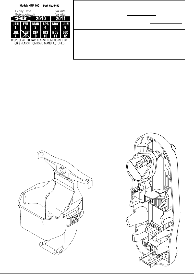
4.3 Hydrostatic release unit (HRU) catagoy 1 beacon
The ACR HydroFix™ HRU has an expiration date of 2 years from the date of installation or
3 years from the date manufactured, whichever comes rst. Upon installing your beacon or
new HRU, permanently scratch the new expiration date on the HRU date calendar (as seen
below).
9Y1-03-0233 Rev. T2
Date of Installation Example:
Date of installation of New HRU or First Installation of
EPIRB including new HRU: August 1, 2007.
This unit will need to be replaced in August of 2009.
Scratch off “AUG 8” and “2006” on the HRU date calendar
Date of Manufacture Example:
On the bottom of the HRU a date of manufacture is pin
stamped: 0806.
This unit will need to be replaced in 0809. Scratch off “AUG
8” and “2009” on the HRU date calendar
The hydrostatic release can be replaced by removing the beacon from the bracket. Firmly
press down on the spring at the bottom of the shelter, then slide the hydrostatic release as-
sembly out of the keyed opening on the spring and mounting bracket. Discard the old HRU.
Check the date manufactured on the bottom of the new HRU and insert the new hydrostatic
release assembly in place by engaging it to the opening of the ejection spring and case.
When replacing the HRU, ACR requires that you do not reuse any parts from the previ-
ous HRU. Failure to replace the entire assembly can cause the bracket to malfunction. Al-
ways use original ACR replacement parts (Replacement kit P/N 9490). Use of unauthorized
replacement parts will void your warranty and may cause the bracket to malfunction. Place
the beacon into the mounting bracket, (lanyard facing inward), and replace cover, securing
in place with the cotter pin going through the hydrostatic release rod.
SECTION 5 – ACTIVATION AND DEPLOYMENT
5.1 Bracketconguration
Bracket Conguration
Figure 2
10
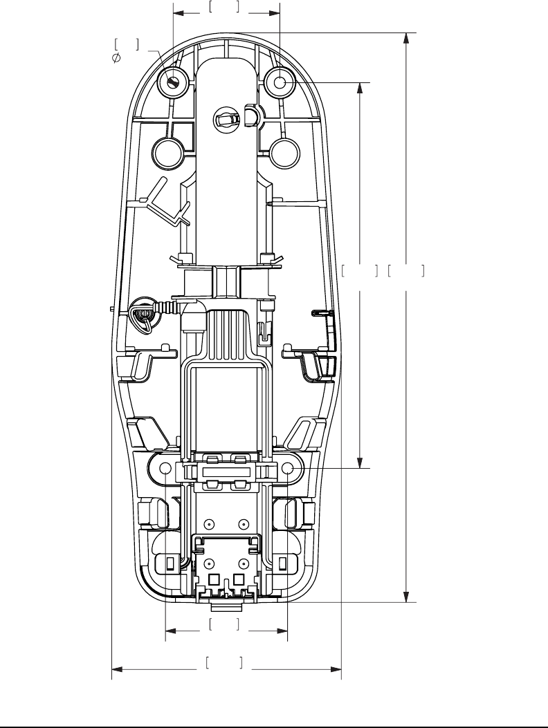
2.621
66.6
9.480
240.8
3
76.2
5.639
143.2
14.001
355.6
.280
7.1
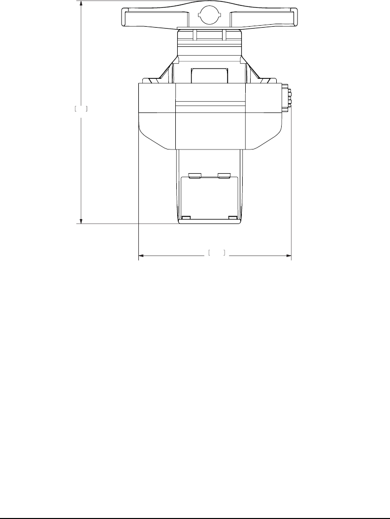
5.2 Category I & 2 bracket dimensions
Category I Bracket NOT TO SCALE
Figure 3
11 Y1-03-0233 Rev. T2
Category II Bracket Dimension Drawing NOT TO SCALE
Figure 4
5.3 Congurationoverview
Category I beacons are designed to be automatically deployed and activated. The beacon
may also be hand held on the deck of vessels, or oated in water and attached to a raft or life
vest with the lanyard provided. Category II beacons are designed to be manually deployed
from the bracket.
The beacon is designed to operate best while oating in water. Hand held operation should
be avoided when possible. Do not operate inside life raft or under any similar cover or
canopy. Use the lanyard to attach beacon to life raft or person after deployment. Caution
- Do not attach lanyard to bracket or vessel. Both models of the beacon can be deployed
and activated manually.
Changes in the laws governing beacons have mandated that the beacon be ready at all
times. If certain criteria are met, the beacon will begin transmitting. The beacon is equipped
with sensors to determine if it is in water (a deployment condition). Category I and II brackets
both contain a magnet that interacts with other sensors in the beacon to prevent activation if
it is wet (also a deployment condition).
Two conditions must be satised for the beacon to automatically activate:
1) It must be out of its bracket
2) It must be in the water
Note: Either condition by itself will not automatically activate the beacon.
4.15
105.5
6.06
154
4.79
121.6
1.28
32.5
4.81
122.2
.13
3.3
1.33
33.7
1.92
48.8
1.11
28.2
12
The beacon is designed to allow the user to perform periodic testing while the beacon is in
the release bracket.
Category I: Place the beacon into the release bracket with the spooled lanyard inward. The
beacon should now be rmly held in the Category I bracket and ready for automatic deploy-
ment. Do not attach lanyard to bracket.
Category II: Place the beacon into the bracket with the spooled lanyard inward. The beacon
should now be rmly held in the Category II bracket and ready for manual deployment. Do
not attach lanyard to bracket. Use the strap and buckle to secure the beacon. The strap
should be adjusted tight against the beacon; tight enough so that it is almost difcult to en-
gage the buckle. This should be checked periodically.
5.4 Automatic deployment and activation - Category I Beacons
Automatic deployment and activation occurs if the vessel sinks and the hydrostatic release
device frees the beacon from the bracket allowing it to oat to the surface. Built-in sensors
detect that the beacon is no longer in its bracket and is in water. This condition will automati-
cally activate the beacon.
A category I RLB-36 automatically activates using the following sequence:
Hydrostatic Release Unit (HRU) releases beacon
Beacon becomes wet
Water acts as condutor, electrical connection is made
Beacon is activated
NOTE: TRANSMISSIONS OF THE 121.5 MHZ AND 406 MHZ SIGNAL WILL NOT OCCUR
UNTIL 100 SECONDS AFTER ACTIVATION.
5.5 Manual deployment and activation
The Category I beacon can be manually deployed by removing the retaining pin, removing
the cover, and then removing the beacon from the bracket. Once removed, both the Catego-
ry I and Category II beacons can be activated by placing the beacon in water OR by lifting
the thumb switch to a vertical position, sliding it toward the antenna and pushing down to the
opposite side of the beacon. Activating the beacon in this manner breaks off the Activation
Indicator Plastic Pin and allows the switch to properly seat, showing the “ ▌ “ symbol (ON).
A category I or category II RLB-36 manually activates with the following sequence:
Remove the beacon from its bracket
Activation method one:
Place beacon in water
Activation method two:
Lift the switch to a vertical position
Slide the switch toward the antenna
Push the switch down to the opposite side of the beacon
OFF position: Note the Activation Indicator Plastic Pin
ON position: Notice the Activation Indicator Plastic Pin
has been broken off.
Figure 5
13 Y1-03-0233 Rev. T2
Note: Some countries may ne vessel owners for causing false alarms. The per-
manent breakage of the Activation Indicator Plastic Pin is a positive indication of
a manual activation.
5.6 Manual activation without deployment
The beacon can be activated while still in its bracket by placing the thumb switch in the ON
position. Activation by this method overrides all sensors and turns the beacon “ON.” The
caution note above still applies.
5.7 Deactivation
If manually activated, return the thumb switch to the “OFF” position.
If automatically activated: remove the beacon from the water. The beacon normally takes up
to 12 seconds to deactivate, or place the beacon back into the release bracket.
If the beacon continues to operate after it has been deactivated, remove the four screws
holding the unit together and unplug the battery to disable the unit. Return it to a service
center for repair.
SECTION - 6 INTERNAL AND EXTERNAL GPS
6.1 Self testing the beacon
The full functional self-test is initiated by momentarily lifting the thumb switch to a vertical
position and holding it in this position for at least one second and at most 4 seconds. A beep
indicates the initiation of the test, and the self test will attempt 5 functional test sequence
as described in Figure 6. The rst red/green LED ash indicates if the electronic witness is
broken. Then if all tests pass, the buzzer will beep an additional ve times as the green LED
lights simultaneously. The last green LED ash and the smiley faces shown on the display
indicates a successful test. However, if the test fails at any step, there will be no beep and
the red LED will ash with the “x” shown on the display. The self-test will stop at that step.
During the self-test, an actual satellite message is transmitted while certain key performance
parameters are measured and recorded. The self-test message is modied to prevent the
satellite from forwarding an alert message during self-test.
The RLB-36 beacon may be self-tested as much as is warranted, up to a mazimum of 60
(sixty) times in the 5 (ve) year life of the battery, or once per month for the life of the bat-
ery.
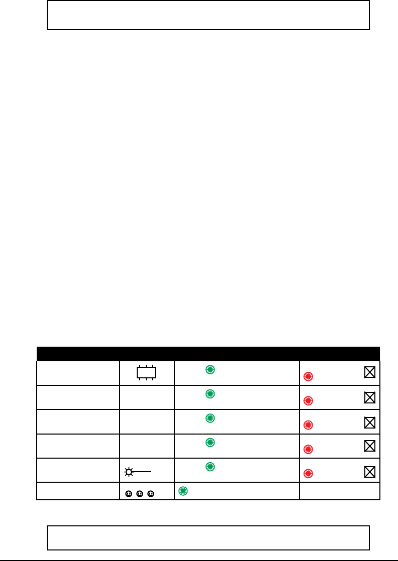
TEST DISPLAY SUCCESS FAIL
EEPROM Connect Beep, Green LED Test Stopped
Red LED
Lock Circuit Beep, Green LED Test Stopped
Red LED
Signal Strength Beep, GreenLED Test Stopped
Red LED
GPS Ready Beep, Green LED Test Stopped
Red LED
Locator Light Beep, Green LED, Strobe Test Stopped
Red LED
Summary Green LED
Figure 6
*NOTE: The “beeps” are a very high-pitched tone that some people may not to
hear. When peroforming the self test, count the red LED ashes .
PLL þ
406 þ
GPS þ
☼ þ
☺☺☺ þ
14
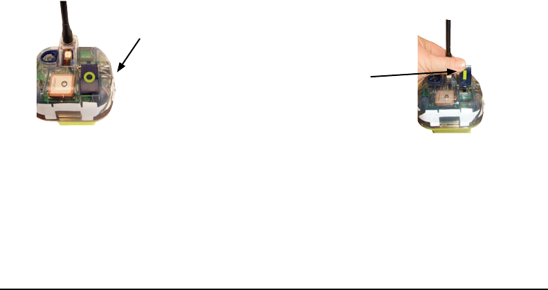
6.2 GPS acquisition with the external GPS
The RLB-36 is tted with an optical interface to connect with an external Global Positioning
System receiver that will determine the latitude and longitude of its position to be transmit-
ted to the emergency system. When RLB-36 is coupled to a working external GPS receiver,
it immediately begins downloading data. Once valid position data has been obtained, the
beacon will attempt to update the positional data every 20 minutes. The RLB-36 will store the
last valid positional data for up to 4 hours, if it becomes unable to obtain new updated data.
It will update this data if and only if it receives new good positional data from the external
GPS receiver.
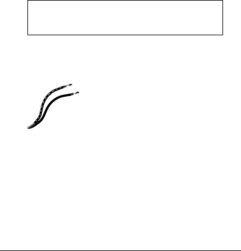
The black lead wire with white stripes should be connected to the positive transmitter pin.
The black wire should be connected to the negative pin.
If the external GPS receiver is operational and the connection has been correctly made to
the optical interface, the green LED in the optical interface will start ashing.
NOTE: The baud rate output for your GPS receiver NMEA 0183 should be 4800
bps. If you are not sure if your receiver is NMEA 0183 compliant, check the inter-
face settings listed in your GPS manual. To optimize your GPS Interface feature be
sure that your GPS receiver is equipped with a NMEA 0183 Version 1.5 or higher
with GPGGA sentence enabled.
6.3 Using the external GPS interface
Once a compatible, operating GPS receiver is connected to RLB-36, the beacon will store
data for incorporation into the emergency message, which is transmitted to the satellite
when it is activated in an emergency. This can provide more accurate positioning data to
the Search and Rescue Authority and may lead to a faster rescue. Since the last valid GPS
position data may stay in the memory for up to 4 hours, the user
should take care to make sure that the GPS position data stored
is accurate. This can be accomplished by two methods: rst,
by always leaving a properly functioning GPS connected to the
beacon before activation and second, by connecting a properly
functioning GPS with a valid position x and allowing sufcient
time to acquire valid GPS position data. This will take a nominal
20 minutes if old GPS position data is stored in the memory. If
there is no old GPS position data present, the beacon will ac-
quire current data within a minute of being connected to a GPS
with a valid position x. You can force the beacon to update its
position at any time by connecting to a GPS with a valid position
x and initiating the Self-Test. If no valid GPS position data is available, the beacon will keep
the previously stored GPS position data for up to 4 hours. In this case, call ACR Customer
Service at +1 (954) 981-3933 for instructions on how to reset the beacon with the default
message.
6.4 Testing the external GPS interface
Connect the optical interface plug to the beacon bezel and allow sufcient time for the GPS
receiver to acquire valid GPS position data (usually less than 1 minute; but it can take up to
20 minutes). Lift the thumb switch to the vertical (Self-Test) position and release. Your bea-
con will conrm that it has acquired valid GPS data by displaying the latitude and longitude
coordinates on the display. This will occur after the “smiley faces” are displayed at the end
of Self-Test.
6.5 Updating the external GPS position data
When the beacon is properly connected to a functioning and compatible GPS receiver, GPS
position data is automatically updated about every 20 minutes, while valid GPS position data
NMEA Cable Wires
Figure 7
15 Y1-03-0233 Rev. T2
is present. The operator can force the acquisition of new GPS position data, by executing
a Self-Test with the beacon connected to a GPS with a valid position x. This bypasses the
normal, programmed, waiting time of 20 minutes for the automatic update of GPS position
data. If the new GPS position is acquired, the coordinates will be displayed, after the beacon
has completed the Self-Test.
A new beacon is programmed with the GPS position data set to “default.” This default GPS
position data indicates, upon activation, to the satellite system that the beacon has no valid
GPS position stored in memory. Once a functioning and compatible GPS receiver is properly
connected to the beacon, this “default” data will be replaced by valid GPS position data, as
described in the previous sections.
6.6 Internal GPS navigation system
The RLB-36 is tted with an internal Global Positioning System receiver that will determine
the navigational coordinates, latitude and longitude, of its position on the globe to be trans-
mitted to the emergency system. The internal GPS will be formatted in accordance with the
NMEA-0183 interface. The serial rate will be 9600 baud, eight data bits, no parity and one
stop bit. When the RLB-36 is turned on the GPS is immediately turned on and it attempts to
acquire good navigation data for a period of 30 minutes. If the GPS receiver obtains good
data anytime in this period or the 30 minutes elapses, the GPS receiver is turned off for 20
minutes and 45 seconds. This is to prevent an update from happening in less than 20 min-
utes. GPS data can be acquired anytime the GPS is on, but only good quality factor data
is recognized and saved. Once the beacon acquires good quality GPS data in this manner
it puts the GPS data into the next transmitted 406 MHz digital message. After the GPS is
turned off for 20 minutes and 45 seconds, the GPS is turned on for ten minutes to attempt
to acquire or update good navigation data. If the GPS acquires good data or the 10-minute
period elapses, the GPS is turned off for another 20 minutes and 45 seconds. The third time
the beacon looks for GPS data the GPS is turned on for 5 minutes. From then on each GPS
on time is 5 minutes and each following off period is increased by an additional 9 minutes
until the GPS has been on fo r a total of 18 periods, at this time the off time the GPS engine
reaches 2.5 hours, then it turns on for 5 minutes then off for 2.5 hours, till the battery dies
out.
6.7 Internal GPS Testing
This test is NOT required as 100% of all GPS receivers that leave ACR have been tested
to ensure they perform perfectly. However, if you would like to ensure your GPS receiver is
working, please follow these instructions very closely.
Warning: To conserve battery power the following test should not be performed
more than once during the ve-year life of the battery pack!
Note: The GPS receiver is located under the top cap (next to the thumb switch). It is impera-
tive that the receiver is not obstructed during self test or activation to ensure that the GPS
receiver is acquiring your latitude (LAT) and longitude (LON) position. This test must be
performed outside with a clear view of the sky.
To test the internal GPS you must be outdoors and have a clear view of the sky. Observe
the beacon for the entire GPS test. Lift the thumb switch to vertical position and hold it in this
position for at least 9 seconds. The “GPS” will display on the OLED and a beep will indicate
that the GPS has been turned on. The GPS will remain ON until LAT/LON coordinates have
been obtained or until 10 minutes have elapsed. If good navigation data has been obtained,
the GPS will be turned OFF and the coordinates will be displayed on the OLED display.
The LAT/LON data is not saved for use when then beacon is turned on and there is no RF
burst during this GPS test. This is only to proof that the GPS is functioning properly and that
the beacon is in a location or environment where it can receive the necessary signals from
satellites. If the GPS does not acquire good navigation data, the GPS will turn OFF after 10
minutes.

16
6.8LEDindicationofGPSx
When the RLB-36 is in On mode, the red LED, Light Emitting Diode, ashes every 1 second
for the rst hour then 3 seconds after to indicate the RLB-36 is turned on and operating. As
soon as the GPS receiver acquires good navigational data the red LED stops blinking and
the green LED ashes once every two seconds to indicate that the internal GPS receiver
has acquired good navigational data. The color of the On mode LED that ashes once every
1 or 3 seconds in On mode always indicates whether the 406 message being transmitted
contains good navigation data or default data. Green indicates good navigation data, red
indicates default data. Once good navigation data is acquired, the data is put into the digital
message of the next 406 MHz transmitted burst. If for any reason a time period of 4 hours
passes without the GPS receiver being able to update the last good set of navigational
data, the message transmitted by the RLB-36 will revert back to default data. At this point
the green LED will stop blinking and the red LED will ash 1 every 3 seconds. If at any time
after this, good navigational data is obtained, the green LED will ash, this new data will
be transmitted in the following burst and the green LED will continue to ash once every 3
seconds.
6.9 OLED display
The Organic Light- Emitting Diode (OLED) display in the beacon is used as a secondary
indicator, supporting the green/red LED and the beep sound to indicate the status of the
beacon during the self test and emergency operation.
In self test, the OLED displays the test result of each step with “√” indicating a pass and “X”
indicating a failure. There are total ve test steps: EEPROM content, phase locker loop, 406
power output, internal GPS module and the strobe light. If all tests pass, “smiley face” emoti-
cons will be displayed at the end of the self test mode. This will be followed by the GPS co-
ordinates horizontally scrolling through the display, provided the beacon has a downloaded
external GPS location.
A long GPS test may be invoked by holding the switch in test position after self test com-
pletes. The display will show the letters “GPS” moving left and right while the internal GPS
is acquiring coordinates data. Once the data is acquired, the coordinates will scroll through
the display as a conrmation that the data was successfully acquired.
When the beacon is activated, the display will show a brief welcome message. The beacon
then begins to send 406 MHz emergency signal bursts. After each 406 burst, indicated by
a beep, GPS coordinates will be displayed, provided the data was acquired. The display
animates the sending of the 406 message. The display also provides a battery gauge which
appears for approximately 10 seconds each time between the 406 bursts.
SECTION 7 – CARE AND MAINTENANCE
7.1 Routine maintenance
At least every ninety days, the oat free mounting bracket and beacon should be inspected
for deterioration and/or residue buildup that may affect the function of the beacon or auto-
matic release. Part of the visual check includes checking the antenna for tightness. Clean
the beacon and the mounting bracket to remove residue buildups. It is recommended that
the beacon and mounting bracket be wiped with a damp cloth.
Carefully inspect the beacon case for any visible cracks. Cracks may admit moisture, which
could falsely activate the beacon or otherwise cause a malfunction. Any cracking observed
should be immediately referred to ACR for evaluation by calling 1-800-432-0227 ext. 2155 in
the US, or +1-954-981-3333 ext 2155 elsewhere.
7.2 Battery replacement
The battery must be replaced by the date indicated on the beacon or every ve (5) years,
whichever occurs rst. At each inspection, check the time remaining until replacement is
required. The battery should be replaced if the beacon has been activated for any use other
than the self test.

17 Y1-03-0233 Rev. T2
Always refer all long life battery replacement and other beacon service to a factory autho-
rized service center. Battery replacement includes servicing the beacon by replacing all
o-rings, testing the water seal and the electrical properties.
NOTE: There are no user serviceable items inside the beacon. DO NOT OPEN THE BEA-
CON UNLESS TO DISABLE IN CASE OF FAULTY ACTIVATION.
For the nearest location of a Battery Replacement Center, visit our website at www.acrelec-
tronics.com
The beacon may or may not require special shipping instructions due to the lithium batteries
and changes in shipping regulations. Please refer to ACR’s website www.acrelectronics.com
for proper shipping instructions.
7.3 Shore based maintenance for SOLAS Vessels
SBM) IMO MSC/Circ. 1039
The Maritime Safety Committee approved guidelines for shore-based maintenance of satel-
lite beacons, for the purpose of establishing standardized procedures and minimum levels of
service for the testing and maintenance of satellite beacons. First Shore Based Maintenance
on all ACR EPIRBs is due at the date of the rst battery replacement.
7.4 Annual testing for SOLAS vessels, IMO MSC/Circ. 1040
SOLAS regulation IV/15.9 dictates annual testing of 406 MHz satellite EPIRBs. Testing
should be carried out using suitable test equipment capable of performing the relevant mea-
surements. All checks of electrical parameters should be performed in the self-test mode,
if possible.
SECTION 8 – THE SEARCH AND RESCUE SYSTEM
8.1 General overview
Beacons provide distress alerts via radio transmission on 406 MHz to the LEOSAR satellites
of the COSPAS-SARSAT network. The beacon can also transmit a distress alert (acquired
by the internal or external GPS) to the GEOSAR network that includes GPS latitude and
longitude coordinates.
The message transmitted is unique for each beacon, which provides identication of the
transmitter through computer access of registration les maintained by the National Oceanic
and Atmospheric Administration or other national authority*. Remember, SAR forces will
know who you are, what type of vessel you have, your home port, and who to contact that
might know of your current situation ONLY if your beacon has been properly registered. This
will help expedite the launch of a rescue operation. 406 MHz beacons are required to have
their registration updated every two years.
*The national authority is the governmental body responsible for EPIRB registration data-
base administration for the country for which the EPIRB is programmed.
Once the 406 MHz signal is relayed
through the LEOSAR and/or GEO-
SAR network, SAR forces determine
who is closest, and then proceed to
the beacon using the 121.5 MHz
homing frequency.
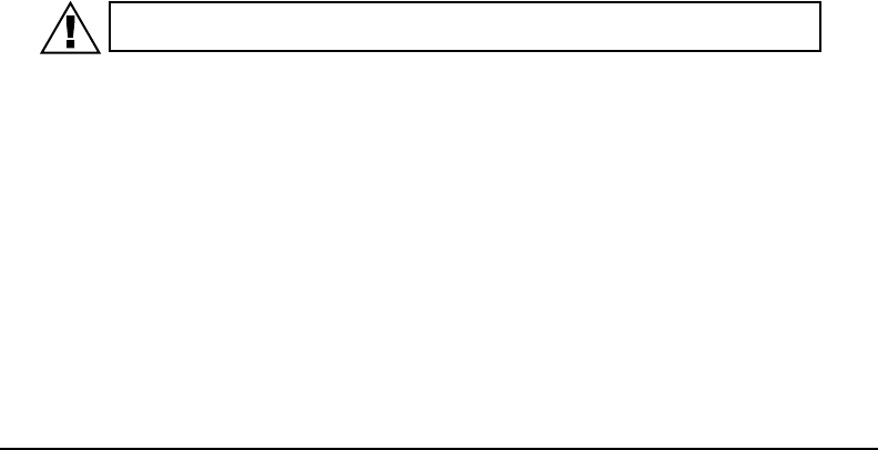
8.2 Satellite detection
EPIRBs transmit to the satellite por-
tion of the COSPAS-SARSAT system.
COSPAS-SARSAT is an international
Figure 9 - Satellite Coverage
18
system that utilizes Russian Federation and
United States’ low altitude, near-polar orbiting
satellites (LEOSAR). These satellites assist in
detecting and locating activated 406 MHz satel-
lite beacons.
COSPAS and SARSAT satellites receive dis-
tress signals from EPIRBs transmitting on the
frequency of 406 MHz. The COSPAS-SARSAT
406 MHz beacon signal consists of a transmis-
sion of non-modulated carriers followed by a dig-
ital message format that provides identication
data. The 406 MHz system uses Satellite-borne
equipment to measure and store the Doppler-
shifted frequency along with the beacon’s digital
data message and time of measurement. This information is transmitted in real time to an
earth station called the Local User Terminal (LUT), which may be within the view of the satel-
lite, as well as being stored for later transmission to other LUTs.
The LUT processes the Doppler-shifted signal from the LEOSAR and determines the loca-
tion of the beacon, then the LUT relays the position of the distress to a Mission Control
Center (MCC) where the distress alert and location information is immediately forwarded
to an appropriate Rescue Coordination Center (RCC). The RCC dispatches Search and
Rescue (SAR) forces.
The addition of the GEOSAR satellite system greatly improves the reaction time for a SAR
event. This satellite system has no Doppler capabilities at 406 MHz, but will relay the dis-
tress alert to any of the LUT stations. When there is GPS data included in the distress mes-
sage, SAR authorities instantly know your location to within 110 yards (100 m). This speeds
up the reaction time by not having to wait for one of the LEOSAR satellite to pass overhead.
Because most of the search and rescue forces presently are not equipped to home in on the
406 MHz Satellite beacons signal, homing must be accomplished at 121.5 MHz.
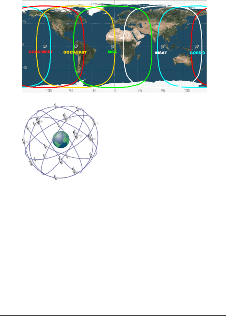
8.3 Global Positioning System (GPS)
The GPS system is a satellite group that enables a GPS receiver to determine its exact posi-
tion to within 30 m (100 ft.) anywhere on earth. With a minimum of 24 GPS satellites orbiting
the earth at an altitude of approximately 11,000 miles they provide users with accurate infor-
mation on position, velocity, and time anywhere in the world and in all weather conditions.
Fig ure 11 - G PS S ate llite
O rbits
Figure 11 - GPS Satellite Orbits
Figure 10 - GEOSAR Satellite Orbits
19 Y1-03-0233 Rev. T2
The GlobalFix™ stores this data into its distress transmission allowing search and rescue
forces to narrow the search into a very small area and thus minimize the resources required
and dramatically increase the effectiveness of the overall operation.
SECTION 9 – TECHNICAL INFORMATION
9.1 Type approvals and standards
The RLB-35 meets the requirements of Federal Communication Commission (FCC) Part 80
and Category I EPIRBs meet the GMDSS requirements:
TYPE APPROVALS
FCC FCC ID: B66ACR-RLB35 (RLB-35)
COSPAS-SARSAT Certicate Nos. 136, 173
MED BSH Certicate No. 4612/506 0016/2005
Notied Body: 0735
Copies of certicates and additional worldwide type approvals are available at:
www.acrelectronics.com.
APPLICABLE STANDARDS
FCC Part 80 Subpart V – EPIRBs
Part 80 Subpart W – GMDSS (Cat. 1 only)
RTCM RTCM Recommended Standards for 406 MHz Satellite EPIRBs
COSPAS/SARSAT C/S T.001 – Specication for C/S 406 MHz Distress Beacons
C/S T.007 –C/S 406 MHz Distress Beacon Type Approval Stan-
dard
MED Annex A.1, Item No. A.1/5.6 – 406 MHz (C/S) Satellite EPIRB
9.2Specications
GENERAL/ENVIRONMENTAL
Beacon size
(without antenna)
17.7 H X 10.67W X 9.09 D cm (6.97 X 4.2 X 3.58 inches)
OLED size 1.0” diagonal
Beacon weight 581 g (18.68 troy oz)
Beacon material High impact UV resistant polymer
Color ACR-treuse™ (high visibility yellow)
Waterproof 10 min @10 m (33 ft), exceeds RTCM standard
Buoyant Yes
Deployment Category I: Automatic hydrostatic release
Category II: Manual
BATTERY
Operational life 48 hours minimum @-20ºC (-4ºF) (Class 2)
Battery type LiMNO2
Battery replacement interval 5 years or after use in an emergency
Operating temperatures -20º C to +55º C (-4º F to +131º F) (Class 2)
Storage temperatures -30º C to +70º C (-22º F to +158º F) (Class 2)

20
406 MHz TRANSMITTER
Frequency 406 MHz
Power output 5 W
Digital message format Standard location protocol (for the USA; Beacon can be repro-
grammed at a service center to other coded formats, and to
national location protocol)
Duration 520 ms
Frequency stability +/- 2 bp/100 ms
Rate 400 bps
Modulation +/- 1.1 radians
Encoding Biphase L
121.5 MHz TRANSMITTER
Frequency 121.5 MHz
Frequency tolerance +/-50 ppm
Power output 25 mW PEP
Modulation type AM (3K20A3X)
Sweep range 400- 1200 Hz
Sweep rate 3 Hz
Duty cycle 37.5%
STROBE
Light color White
Output power 0.75 effective candela
Flash rate 20- 30/ min
ANTENNA
Height 21.21 cm (8.35 in)
Frequency 406 MHz, 121.5 MHz
Polarization Vertical
VSWR Less than 1.5/1
GPS antenna 12 channel parallel receiver
GENERAL
Accessories Category I Mounting Case, ACR Part Number A3-06-2577
Category II Mounting Brackets, ACR Part Number A3-06-2578
Universal Hydrostatic Release (HRU) Kit, ACR Part Number
A3-06-2429-3
Replacement antenna, ACR Part Number A3-06-2554
21 Y1-03-0233 Rev. T2
9.3 Support
ISSUE CONTACT TELEPHONE or WEBSITE
Possible damage to
beacon
ACR Electronics, Inc. US: 1-800- 432- 0227, extension
2155
Outside the US: +1-954-981-3333,
extension 2155
Resetting beacon to allow
downloading new GPS
coordinates
ACR Electronics, Inc. +1-954-981-3333
General trouble with new
beacon
ACR Electronics, Inc. 1-800- 432- 0227
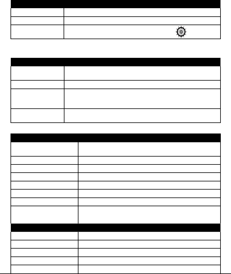
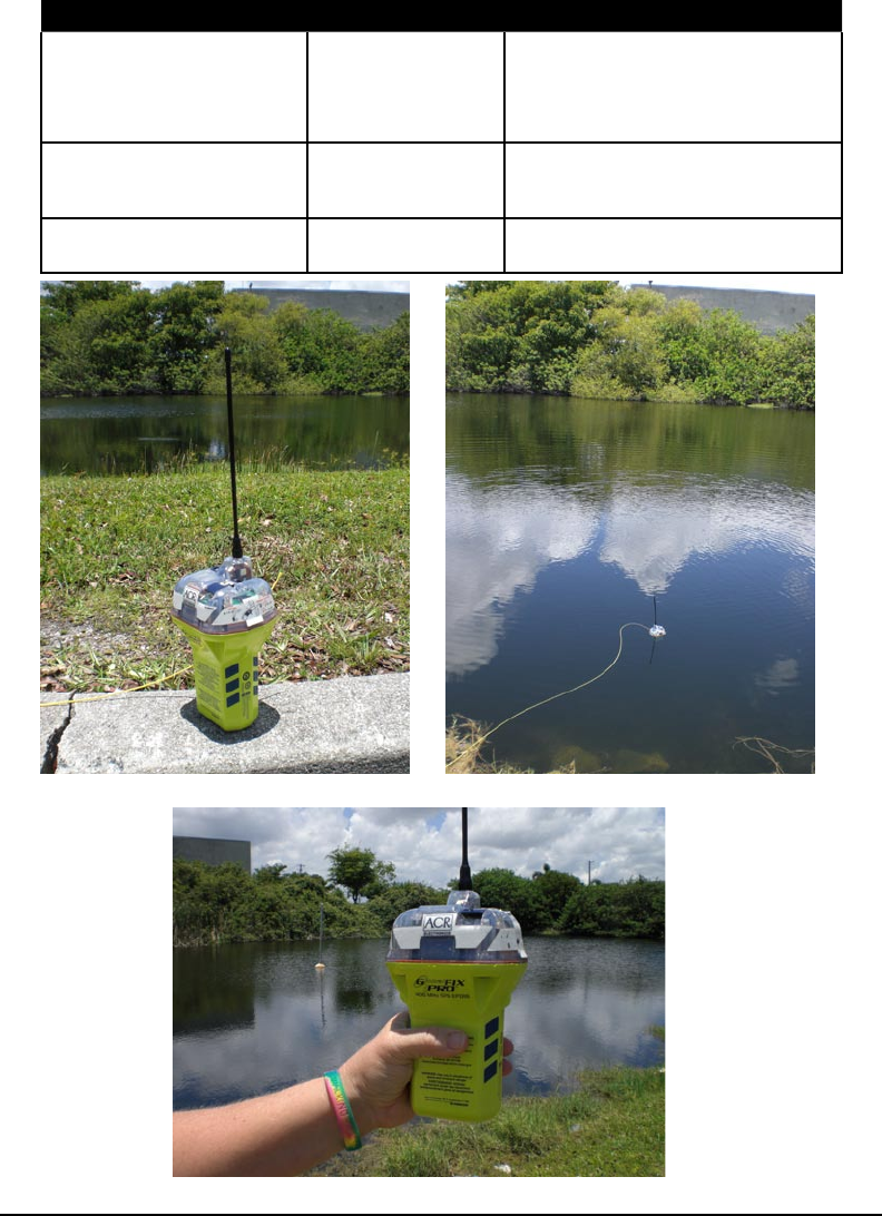
9.4 Beacon Images
Beacon standing upright
Beacon held in hand
Beacon oating in water