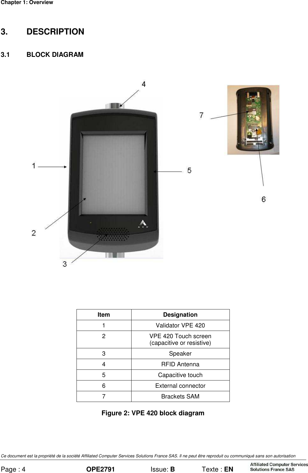
ACS Solutions FranceS
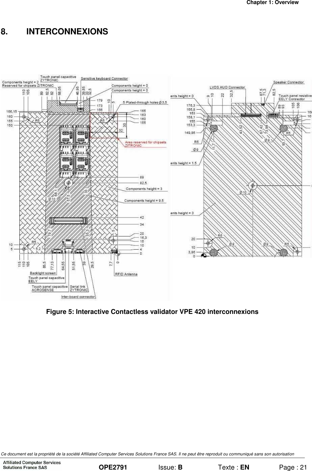
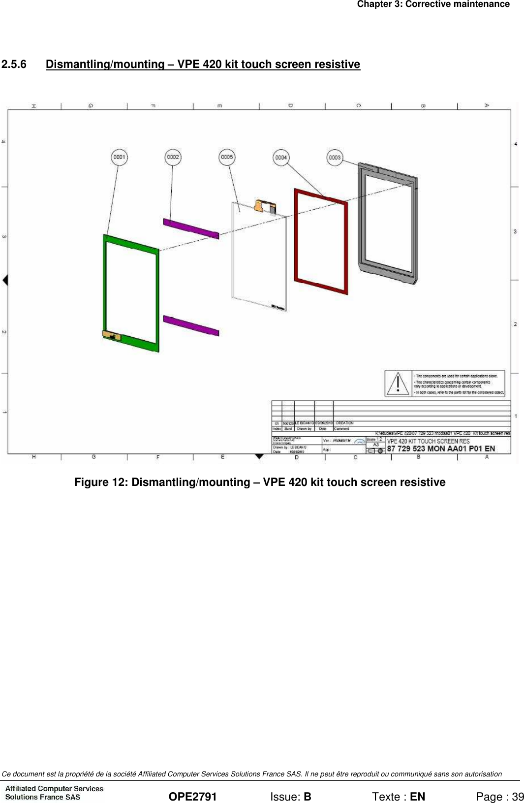
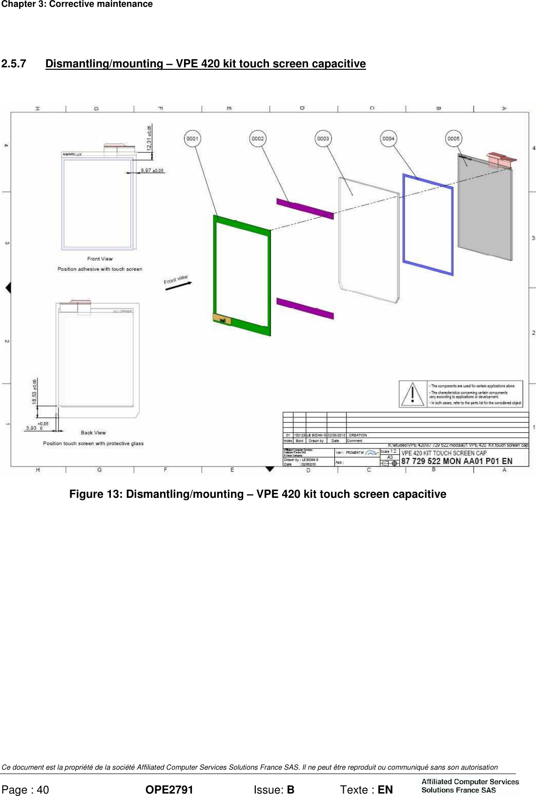
 VPE420 Interactive Contactless Validator User Manual EN OPE2791 B

ACS Solutions France SAS Interactive Contactless Validator EN OPE2791 B

user manual

  Diffusion interne/Internal diffusion 1 Binding:  A = Simple Stapling  B = Binding   C = Hole Perforation  M = Distribution by Mail  Reference : OPE2791 Revision :  B Text : EN Titre/Title INTERACTIVE CONTACTLESS VALIDATOR VPE420 ON-SITE AND WORKSHOP MAINTENANCE MANUAL Affaire/Subject : - - - Classement fichier informatique : Computer file classification :  DTAO Classement original papier : Hard copy classification :  SERVICE CLIENT PEAGE/TOLL SYSTEM CUSTOMER SERVICE Destinataires/To Nbr. of copies Rel1  /Binding1 Observations/Comments DTAO      Circulation sheet        BERNARD J-L    M   BERNE G   M   CARRON E    M   CHIZAT G    M   COURTIAL R.    M   FROMENT M    M   GUETTARD F    M   LACOUR M    M   LEBIDAN G    M   MARROT A    M   MOURADKHANIAN A    M   SAINTCIERGE Y    M   VALETTE P    M   VIAL-TISSOT S    M   VILLERET E    M
    - - - Reference: OPE2791 Revision:  B Text: EN This document is property of the association Affiliated Computer Services Solutions France SAS. It can not be reproduced or distributed without prior authorization.   INTERACTIVE CONTACTLESS VALIDATOR VPE420 ON-SITE AND WORKSHOP MAINTENANCE MANUAL
 This document is property of the association Affiliated Computer Services Solutions France SAS. It can not be reproduced or distributed without prior authorization.    OPE2791  Issue: B  Text: EN  Page: M1 Contact Details Affiliated Computer Services Solutions France SAS Customer Service: *  Address  :  Affiliated Computer Services Solutions France SAS, Rue Claude Chappe - BP 345 07503 GUILHERAND GRANGES CEDEX (FRANCE) Phone   :  33. (0)4.75.81.42.21   Fax  :  33. (0)4.75.81.43.38 Return Service (repair): *  Adresse  :  ASCODI Industries SAS 1 rue Gilles de Roberval Quartier Briffaut - BP 161 26906 VALENCE Cedex 9 (FRANCE)   Téléphone  :  33 (0)4 75 81 42 77   Télécopie  :  33 (0)4 75 81 84 41   *  Adresse  :  Affiliated Computer Services Solutions France SAS Service Clients Public Transport  12, rue Jules Ferry 93110 ROSNY-SOUS-BOIS (FRANCE)   Téléphone  :  33.(0)1.56.63.92.00   Télécopie  :  33.(0)1.56.63.92.22
 This document is property of the association Affiliated Computer Services Solutions France SAS. It can not be reproduced or distributed without prior authorization. Page: M2 OPE2791  Issue: B  Text: EN     WARNING THIS DOCUMENT DESCRIBES ALL THE FUNCTIONS AND OPTIONS THAT CAN BE IMPLEMENTED ON THIS EQUIPMENT. IN THIS DOCUMENT, THE FIGURES AND DRAWINGS ARE PROVIDED ONLY AS EXAMPLE. IN THIS DOCUMENT, MMI SCREENS OF SOFTWARE TOOLS ARE PROVIDED AS EXAMPLE.AND CAN BE GIVEN IN EITHER FRENCH OR ENGLISH LANGUAGE. THE MMI LANGUAGE IS A SETTING PARAMETER. IN ORDER TO KNOW YOUR EQUIPMENT SETTINGS, REFER TO THE HARDWARE SPECIFICATIONS OF THE EQUIPMENT.
 This document is property of the association Affiliated Computer Services Solutions France SAS. It can not be reproduced or distributed without prior authorization.    OPE2791  Issue: B  Text: EN  Page: M3  Modification Sheet  Revision Approval: B  Name  Position Signature Written by: G. BERNE  Customer Service               Checked or Approved by:  P. VALETTE  Technical Project Leader               Authorized by : A. MARROT  Head of Customer Service                        Revision  Validation/ Application Date  No. of Pages No. of Attached Pages  Object and Description of Modification A  November 29, 2010  46  0  First issue. B  February 01, 2011  46  0  Second issue: Modification for FCC and IC certification  In this document the association of "Affiliated Computer Services Solutions France SAS" is designated by the following abbreviation: ACS.
 This document is property of the association Affiliated Computer Services Solutions France SAS. It can not be reproduced or distributed without prior authorization.  OPE2791  Issue: B  Text: EN  Page: S1 TABLE OF CONTENTS Page CHAPTER 1 : OVERVIEW ..................................................................................................  1 1. ABBREVIATIONS..................................................................................................  1 2. PRESENTATION...................................................................................................  2 2.1 GENERAL PRESENTATION.................................................................................  2 3. DESCRIPTION.......................................................................................................  4 3.1 BLOCK DIAGRAM ................................................................................................  4 3.2 DESCRIPTION OF FUNCTIONS ...........................................................................  5 3.2.1 Validator casing......................................................................................................  5 3.2.2 Support ..................................................................................................................  5 3.2.3 Internal resources ..................................................................................................  5 3.2.4 Touch screen .........................................................................................................  5 3.2.5 Sound module........................................................................................................  5 3.2.6 Contactless interface..............................................................................................  6 3.2.7 Communication interfaces......................................................................................  6 4. MODES OF OPERATION......................................................................................  7 5. MAIN CHARACTERISTICS...................................................................................  8 5.1 PHYSICAL CHARACTERISTICS ..........................................................................  8 5.2 ENVIRONMENTAL CHARACTERISTICS .............................................................  8 5.2.1 Climatic characteristics...........................................................................................  8 5.2.2 Electrical characteristics.........................................................................................  8 5.3 FUNCTIONAL CHARACTERISTICS.....................................................................  9 6. EXTERNAL CONNECTIONS.................................................................................  10 6.1 VALIDATOR CONNECTION .................................................................................  11 6.2 CONNECTIONS ON CONNECTION BOARD........................................................  12 6.2.1 Details of the connections bo  ard ..........................................................................  13 7. CONFIGURATION VPE420...................................................................................  18 7.1 VALIDATOR ADDRESS........................................................................................  18 7.2 CONFIGURATIONS AND POLARISATION COM 1 ET COM2..............................  19 7.2.1 Configuration COM1...............................................................................................  19 7.2.2 Configuration COM 2..............................................................................................  20 8. INTERCONNEXIONS ............................................................................................  21 9. DOCUMENTATION OF ASSOCIATED EQUIPMENT ...........................................  22
 This document is property of the association Affiliated Computer Services Solutions France SAS. It can not be reproduced or distributed without prior authorization. Page: S2 OPE2791  Issue: B  Text: EN  CHAPTER 2 : PREVENTIVE MAINTENANCE ...................................................................   23 1. CHANGING “OPERATIONAL” CONSUMABLES................................................   23 2. ON-SITE PREVENTIVE MAINTENANCE .............................................................   24 2.1 PURPOSE OF THE ON SITE PREVENTIVE MAINTENANCE .............................   24 2.2 NECESSARY TOOLS...........................................................................................   24 2.3 ON SITE PREVENTIVE MAINTENANCE OPERATIONS .....................................   24 3. PREVENTIVE MAINTENANCE IN WORKSHOP..................................................   25 3.1 PURPOSE OF THE WORKSHOP PREVENTIVE MAINTENANCE ......................   25 3.2 NECESSARY TOOLS...........................................................................................   25 3.3 ON SITE PREVENTIVE MAINTENANCE OPERATIONS .....................................   25 CHAPTER 3 : CORRECTIVE MAINTENANCE ..................................................................   27 1. ON-SITE CORRECTIVE MAINTENANCE.............................................................   27 1.1 PURPOSE OF SITE MAINTENANCE...................................................................   27 1.2 NECESSARY TOOLS...........................................................................................   27 1.3 SITE CHECKLIST AND REPAIR ACTIONS FOR FAILURE AND ALARM CODES  27 1.3.1 Component code (atlas system) ............................................................................   27 1.3.2 Alarm Code: XXX (atlas system) ...........................................................................   27 1.3.3 List of alarms.........................................................................................................   27 1.4 TABLE OF FAULT CODES ..................................................................................   28 1.4.1 Power up of the VPE 420 ......................................................................................   29 1.4.2 Application launch .................................................................................................   29 1.4.3 Application load Procedure in cases where the VPE 420 is on boot ......................   29 1.4.4 Maintenance menu integral to application software ...............................................   29 1.5 INITIALIZING VPE 420 .........................................................................................   30 1.6 TESTS...................................................................................................................   30 1.6.1 Processing of a transport medium .........................................................................   30 1.6.2 Functional tests .....................................................................................................   30 1.7 VPE 420 EXCHANGE ...........................................................................................   31 1.8 SUBASSEMBLIES EXCHANGE...........................................................................   32 1.8.1 SAM EXCHANGE..................................................................................................   32 2. CORRECTIVE MAINTENANCE IN THE WORKSHOP.........................................   33 2.1 PURPOSE OF CORRECTIVE MAINTENANCE IN THE WORKSHOP.................   33 2.2 NECESSARY TOOLS...........................................................................................   33 2.3 ADJUSTMENTS....................................................................................................   33 2.4 TEST .....................................................................................................................   34
 This document is property of the association Affiliated Computer Services Solutions France SAS. It can not be reproduced or distributed without prior authorization.  OPE2791  Issue: B  Text: EN  Page: S3 2.5 SUBASSEMBLIES EXCHANGE ...........................................................................  34 2.5.1 Particular point due to the replacement ..................................................................  34 2.5.2 Dismantling/mounting – VPE 420...........................................................................  35 2.5.3 Dismantling/mounting – VPE 420 Front hood assembly.........................................  36 2.5.4 Dismantling/mounting – VPE 420 rear hood assembly...........................................  37 2.5.5 Dismantling/mounting – VPE 420 Frame assembly................................................  38 2.5.6 Dismantling/mounting – VPE 420 kit touch screen resistive ...................................  39 2.5.7 Dismantling/mounting – VPE 420 kit touch screen capacitive.................................  40 ANNEX 1:......INTERVENTION AND TROUBLESHOOTING FILE .....................................  41 1. COMPOSITION......................................................................................................  41 2. MODE OF USE......................................................................................................  41 3. DESCRIPTION OF HEADINGS/LINE ITEMS ........................................................  41 3.1 FRAME 1 ...............................................................................................................  41 3.2 FRAME 2 ...............................................................................................................  41 3.3 FRAME 3 ...............................................................................................................  41 3.4 FRAME 4 ...............................................................................................................  41 ANNEX 2:......APPENDIX – "PRECAUTIONS AND SAFETY" ...........................................  43 1. PRESENTATION...................................................................................................  43 2. CERTIFICATION ...................................................................................................  43 3. EXTERNAL CONNECTION...................................................................................  43 3.1 POWER SUPPLY ..................................................................................................  43 3.2 SIGNALS...............................................................................................................  43 4. PRECAUTIONS.....................................................................................................  44 4.1 DISCONNECTING THE EQUIPMENT...................................................................  44 4.2 VENTILATION .......................................................................................................  44 4.3 ELECTRONIC CARD.............................................................................................  44 4.3.1 Special Cases ........................................................................................................  44 4.4 PACKAGING .........................................................................................................  44 4.5 CONTACTLESS FUNCTION FOR INDUSTRY CANADA AND FCC.....................  44 5. SAFETY.................................................................................................................  45 6. STANDARDS.........................................................................................................  46 7. REPAIRS...............................................................................................................  46 8. CONCLUSION.......................................................................................................  46
 This document is property of the association Affiliated Computer Services Solutions France SAS. It can not be reproduced or distributed without prior authorization. Page: S4 OPE2791  Issue: B  Text: EN  LIST OF FIGURES Page Figure 1: Interactive contactless validator + flange assembly.......................................   2 Figure 2: VPE 420 block diagram.....................................................................................   4 Figure 3: Presentation of the external connection..........................................................   10 Figure 4: Connection board..............................................................................................   12 Figure 5: Interactive Contactless validator VPE 420 interconnexions ..........................   21 Figure 6: VPE 420 exchange.............................................................................................   31 Figure 7: SAM exchange...................................................................................................   32 Figure 8: Dismantling/mounting – VPE 420.....................................................................   35 Figure 9: Dismantling/mounting – VPE 420 Front hood assembly................................   36 Figure 10: Dismantling/mounting – VPE 420 rear hood assembly ................................   37 Figure 11: Dismantling/mounting – VPE 420 Frame assembly ......................................   38 Figure 12: Dismantling/mounting – VPE 420 kit touch screen resistive .......................   39 Figure 13: Dismantling/mounting – VPE 420 kit touch screen capacitive.....................   40
Chapter 1: Overview Ce document est la propriété de la société Affiliated Computer Services Solutions France SAS. Il ne peut être reproduit ou communiqué sans son autorisation  OPE2791  Issue: B  Texte : EN  Page : 1 CHAPTER 1: OVERVIEW 1.  ABBREVIATIONS VPE 420  Interactive contactless validator type VPE420 CPU  Central Processing Unit FLASH  Electrically Programmable Memory (parallel access) LCD  Liquid Cristal Display LED  Light Emitting Diode MMI  Man machine Interface N.U.  Not Used RS232   RS422  Standard data links RS485 Ethernet TLB  Teleticketing (ContactLess Ticketing)
Chapter 1: Overview Ce document est la propriété de la société Affiliated Computer Services Solutions France SAS. Il ne peut être reproduit ou communiqué sans son autorisation Page : 2 OPE2791  Issue: B  Texte : EN  2.  PRESENTATION 2.1  GENERAL PRESENTATION This device is a contactless reader-encoder unit which processes ISO/IEC 14 443-compliant contactless cards. With its modern design similar to mobile communication devices, this interactive validator VPE420 is much more than a simple validation tool. With a large color touch screen and voice synthesis, it is a truly modern communication tool, prestigious for the image of transport networks. The screen offers a contextual display which indicates only the right information at the right time (contactless target, keys, pictograms…). This helps user understanding and the flow of validations is therefore increased. Of an innovative concept, the wide-range contactless antenna integrated in the screen enables the easy validation of all types of contactless media: card, ticket, NFC telephone, NFC Smart Object, simply by placing the media in front of the screen when invited to do so. Activated on request, the voice synthesis effectively guides users with sight impairments. Over and beyond ticketing, the combination of sound, image and touch enables a multitude of possibilities such as the display and vocal announcement of the next stop, transmission of passenger information messages; performing "on the spot" satisfaction surveys, transmission of video spots or advertising banners … However with all this, the validator still remains reliable, robust and ecological. In fact it contains no battery, which reduces its impact on the environment and eliminates preventive maintenance operations.  Figure 1: Interactive contactless validator + flange assembly
Chapter 1: Overview Ce document est la propriété de la société Affiliated Computer Services Solutions France SAS. Il ne peut être reproduit ou communiqué sans son autorisation  OPE2791  Issue: B  Texte : EN  Page : 3 The validator can be fixed on a vertical tube of 25 to 35 mm diameter through a support which integrates and hides the connectors and cables.    Once installed on its support the validator is slightly inclined to facilitate reading and entry on the screen. The support integrates an identification memory module which enables the memorization of information such as the identification of the validator, of the vehicle, its IP address... Thus, in case of replacement of the validator, the new one automatically recovers the context information. The unit is locked by a hidden lock underneath the support. Unlocking opens a flap with gives access to a USB connector thus enabling the connection of a USB peripheral (key, keyboard, mouse).   Tube Support Validator
Chapter 1: Overview Ce document est la propriété de la société Affiliated Computer Services Solutions France SAS. Il ne peut être reproduit ou communiqué sans son autorisation Page : 4 OPE2791  Issue: B  Texte : EN  3.  DESCRIPTION 3.1  BLOCK DIAGRAM   Item  Designation 1  Validator VPE 420 2  VPE 420 Touch screen (capacitive or resistive) 3  Speaker 4  RFID Antenna 5  Capacitive touch 6  External connector 7  Brackets SAM Figure 2: VPE 420 block diagram
Chapter 1: Overview Ce document est la propriété de la société Affiliated Computer Services Solutions France SAS. Il ne peut être reproduit ou communiqué sans son autorisation  OPE2791  Issue: B  Texte : EN  Page : 5 3.2  DESCRIPTION OF FUNCTIONS For details, refer to the interactive contactless validator VPE 420 hardware specifications. 3.2.1  Validator casing This comprises a front and rear cover in molded ABS/PC with no screw apparent when the validator is mounted on its support. 3.2.2  Support It consists of an aluminium flange attached to the tube by 2 threaded rods bent into a U and a flange cover moulded in ABS-PC attached to the flange to decorate the back of validator. The flange has an anti-rotation peg to prevent the validator to turn around the tube. As an option, the validator may be supplied with a support enabling its mounting on a flat surface (wall, panel…). 3.2.3  Internal resources −  ARM core processor. −  Memories: SDRAM: 128 Mbytes FLASH: 256 Mbytes extensible to 32 Gbytes −  Identification module (present in the support): 256 bytes. −  Calendar, protected at least 3 days in the event of power supply cutout. −  Operating system: Windows CE 6.0 R3. 3.2.4  Touch screen 6"5 TFT screen mounted in portrait mode. −  Technology:  color TFT graphic. −  Definition:  640 x 480 pixels (VGA). −  Touch panel:  Projected capacitive, or resistive. 3.2.5  Sound module The sound module is formed by a loudspeaker by which pre-recorded messages or sounds are broadcast in Wav or MP3 format (optional) with a sound rating of up to 72 dB at 1 m.
Chapter 1: Overview Ce document est la propriété de la société Affiliated Computer Services Solutions France SAS. Il ne peut être reproduit ou communiqué sans son autorisation Page : 6 OPE2791  Issue: B  Texte : EN  3.2.6  Contactless interface The contactless interface comprises: −  A radio coupler complying with standard ISO/IEC 14443 (type A and B) supporting the Innovatron B’ protocol. Optionally, the coupler can integrate the Felica standard (Type C) and be "EMV contactless" compatible. −  An antenna. −  Four SAM supports. Main characteristics of interface: −  Carrier frequency: 13.56 MHz. −  Communication speed with contactless card: up to 424 Kbit/s. −  Range: 0 to 10 cm depending on type of contactless media. 3.2.7  Communication interfaces 3.2.7.1  RS232/RS422/RS485/SAEJ1708 Two ports, configurable for RS232 or RS422 or RS485, with one configurable additionally for SAEJ1708. 3.2.7.2  Ethernet One Ethernet, 10/100 base TX. 3.2.7.3  USB One USB 2.0 master interface; accessible under the validator after unlocking. 3.2.7.4  Input - Output interfaces Two opto-isolated inputs and four dry contact outputs.
Chapter 1: Overview Ce document est la propriété de la société Affiliated Computer Services Solutions France SAS. Il ne peut être reproduit ou communiqué sans son autorisation  OPE2791  Issue: B  Texte : EN  Page : 7 4.  MODES OF OPERATION According to the address to which the validator is wired, it can work in “master” or “slave” mode of peripheral equipment. “Master” Mode In this mode, the validator is master of the dialogue between equipment (console, beacons, validator, etc.). Data exchange and loading of the RTP file may be carried out: −  through an infrared connection from a portable terminal, −  or through a beacon or WiFi system to a land site. Generally, this mode is used when the validator is alone. "Slave" Mode In this case, the validator is linked in long distance transmission through a serial connection to the master equipment (console or validator). Generally, this mode is used as slave of a master validator or when the console has a printer.  “Autonomous” Mode Thanks to the internal ticket machine and a back up memory, the validator may function in “autonomous” mode, i.e. not connected to master equipment.  “Degraded” Mode Due to a dialogue failure, the validator may function in “degraded” mode until the system works correctly again. This functioning mode is defined by application parameters. During this mode, the validations are memorized and will be transmitted to the master machine when the dialogue is resumed.  Refer to the interactive contactless validator VPE 420 hardware specifications, functional specifications.
Chapter 1: Overview Ce document est la propriété de la société Affiliated Computer Services Solutions France SAS. Il ne peut être reproduit ou communiqué sans son autorisation Page : 8 OPE2791  Issue: B  Texte : EN  5.  MAIN CHARACTERISTICS 5.1  PHYSICAL CHARACTERISTICS −  Height:  approximately 250 mm −  Width:  approximately 146 mm −  Depth:  approx. 95 mm (in relation to the front of the tube) −  Weight of the Validator with the flange support: < 1,5 Kg approximately These values are given for the Validator + flange assembly. 5.2  ENVIRONMENTAL CHARACTERISTICS 5.2.1  Climatic characteristics −  Operating temperature range:  -25°C to +55°C −  Storage temperature range:  -30°C to +70°C −  Humidity:  95% HR −  Without condensation at 35°C −  Protection index:  IP54. −  Protection impact index IK07. 5.2.2  Electrical characteristics  The Validator is powered on vehicles equipped with a nominal 12-Volt or 24-Volt battery. −  For 24 Vdc Battery 18 Vdc to 32 Vdc.   24Vdc nominal Maximum power consumption  600mA −  For 12 Vdc Battery 9 Vdc to 16 Vdc.   12Vdc nominal Maximum power consumption  1200mA The Validator is protected against polarity reversals and against power surges. The Validator’s power line must be protected by a circuit breaker or fuse, calibrated as follows: −  2 amperes for one Validator – VPE420. −  4 optional digital outputs (isolated relay): 2 SPST-NO relays isolated outputs 2 SPDT relays isolated outputs Contacts ratings: Max switching voltage: 60VDC Max switching current: 1A Contacts protections against overvoltage and over current due to switching operations.
Chapter 1: Overview Ce document est la propriété de la société Affiliated Computer Services Solutions France SAS. Il ne peut être reproduit ou communiqué sans son autorisation  OPE2791  Issue: B  Texte : EN  Page : 9 −2 optional opto-coupled isolated inputs: Forward voltage: from 8VDC to 60 VDC. Forward current: 10 mA. Protection against reverse voltage. 5.3  FUNCTIONAL CHARACTERISTICS Refer to the interactive contactless validator VPE 420 functional specifications.
Chapter 1: Overview Ce document est la propriété de la société Affiliated Computer Services Solutions France SAS. Il ne peut être reproduit ou communiqué sans son autorisation Page : 10 OPE2791  Issue: B  Texte : EN  6.  EXTERNAL CONNECTIONS     Figure 3: Presentation of the external connection  Link to support kit for external connections (power, serial connections, maintenance) Flange assembly
Chapter 1: Overview Ce document est la propriété de la société Affiliated Computer Services Solutions France SAS. Il ne peut être reproduit ou communiqué sans son autorisation  OPE2791  Issue: B  Texte : EN  Page : 11 6.1  VALIDATOR CONNECTION Refer to the interactive contactless validator VPE 420 hardware specifications. The functional connections of VPE 420 are made through a single male connector (J2), Connector type 50P TX25-50P-8ST-H1E: −  DC power supply: +24V, −  the COM1 to COM2 links, −  the Relay outputs, −  the isolated inputs, −  one USB 2.0 master interface, −  the Ethernet link (COM4). Connecteur J2 of UC board: External Connection:
Chapter 1: Overview Ce document est la propriété de la société Affiliated Computer Services Solutions France SAS. Il ne peut être reproduit ou communiqué sans son autorisation Page : 12 OPE2791  Issue: B  Texte : EN  6.2  CONNECTIONS ON CONNECTION BOARD  Figure 4: Connection board Connector J2: power supply Connector J7: COM 1 and COM2 only RS485 and RS422 configured Connector J6: COM 1 and COM2 only RS232 configured, and Ethernet COM Connector J5: several configuration of two outputs Connector J4: two inputs and one outputs Connector J31: COM2 SAEJ1708 configured
Chapter 1: Overview Ce document est la propriété de la société Affiliated Computer Services Solutions France SAS. Il ne peut être reproduit ou communiqué sans son autorisation  OPE2791  Issue: B  Texte : EN  Page : 13 6.2.1  Details of the connections board  Connector  Schema Connector J2: power supply  Pin1 : VP Pin 2 : PGND Connector J7: COM1 and COM2 only RS485 and RS422 configured
Chapter 1: Overview Ce document est la propriété de la société Affiliated Computer Services Solutions France SAS. Il ne peut être reproduit ou communiqué sans son autorisation Page : 14 OPE2791  Issue: B  Texte : EN   Connector  Schema Connector J6: COM1 and COM2 only RS232 configured, and Ethernet COM  Connector J5: several configuration of two outputs
Chapter 1: Overview Ce document est la propriété de la société Affiliated Computer Services Solutions France SAS. Il ne peut être reproduit ou communiqué sans son autorisation  OPE2791  Issue: B  Texte : EN  Page : 15  Connector  Schema Connector J4: two inputs and one outputs  Connector J31: COM2 SAEJ1708 configured
Chapter 1: Overview Ce document est la propriété de la société Affiliated Computer Services Solutions France SAS. Il ne peut être reproduit ou communiqué sans son autorisation Page : 16 OPE2791  Issue: B  Texte : EN   Connector  Schema Connector J38: for USB KEY, USB KEYBOARD, etc.  Connector J3: for DEBUG and OS download
Chapter 1: Overview Ce document est la propriété de la société Affiliated Computer Services Solutions France SAS. Il ne peut être reproduit ou communiqué sans son autorisation  OPE2791  Issue: B  Texte : EN  Page : 17  Connector   Schema Connector J8: LAN socket is for debug only
Chapter 1: Overview Ce document est la propriété de la société Affiliated Computer Services Solutions France SAS. Il ne peut être reproduit ou communiqué sans son autorisation Page : 18 OPE2791  Issue: B  Texte : EN  7.  CONFIGURATION VPE420 7.1  VALIDATOR ADDRESS Addressing is done by switches SW2 of the VPE420 connection board.  Address  SW2 number 1  SW2 number 2  SW2 number 3  SW2 number 4  Signal  RT_ADDR3  RT_ADDR2  RT_ADDR1  RT_ADDR0 VPE420 N° 0  OFF  OFF  OFF  OFF VPE420 N° 1  OFF  OFF  OFF  ON VPE420 N° 2  OFF  OFF  ON  OFF VPE420 N° 3  OFF  OFF  ON  ON VPE420 N° 4  OFF  ON  OFF  OFF VPE420 N° 5  OFF  ON  OFF  ON VPE420 N° 6  OFF  ON  ON  OFF VPE420 N° 7  OFF  ON  ON  ON VPE420 N° 8  ON  OFF  OFF  OFF VPE420 N° 9  ON  OFF  OFF  ON VPE420 N° 10  ON  OFF  ON  OFF VPE420 N° 11  ON  OFF  ON  ON VPE420 N° 12  ON  ON  OFF  OFF VPE420 N° 13  ON  ON  OFF  ON VPE420 N° 14  ON  ON  ON  OFF VPE420 N° 15  ON  ON  ON  ON Warning:  Switches are set 1 when they are set on position "ON".
Chapter 1: Overview Ce document est la propriété de la société Affiliated Computer Services Solutions France SAS. Il ne peut être reproduit ou communiqué sans son autorisation  OPE2791  Issue: B  Texte : EN  Page : 19 7.2  CONFIGURATIONS AND POLARISATION COM 1 ET COM2 7.2.1  Configuration COM1  CONFIG COM1 SW1.10  SW1.9  SW1.8  SW1.7  SW1.6  SW1.5  SW1.4  SW1.3  SW1.2  SW1.1 RS-232  N.U  OFF  OFF  OFF  OFF  OFF  OFF  OFF  OFF  OFF RS-422 non- polarized and non adapted N.U  OFF  OFF  OFF  OFF  OFF  OFF  OFF  OFF  ON RS-485 non- polarized and non adapted N.U  OFF  OFF  OFF  OFF  OFF  OFF  ON  ON  ON RS-422 polarized and adapted N.U  ON  ON  ON  ON  ON  ON  OFF  OFF  ON RS-485 polarized and adapted N.U  OFF  OFF  OFF  ON  ON  ON  ON  ON  ON When The COM1 is configured in RS 422 −  SW1.4:  Enable to polarize TX1_422+ with a pull-up −  SW1.5:  Enable to adapt the emission of RS422 −  SW1.6:  Enable to polarize TX1_422- with a pull-down −  SW1.7:  Enable to polarize RX1_422+ with a pull-up −  SW1.8:  Enable to adapt the reception of RS422 −  SW1.9:  Enable to polarize RX1_422- with a pull-down
Chapter 1: Overview Ce document est la propriété de la société Affiliated Computer Services Solutions France SAS. Il ne peut être reproduit ou communiqué sans son autorisation Page : 20 OPE2791  Issue: B  Texte : EN  7.2.2  Configuration COM 2  CONFIG COM2 SW3.10  SW3.9  SW3.8  SW3.7  SW3.6  SW3.5  SW3.4  SW3.3  SW3.2  SW3.1 RS-232  OFF  OFF  OFF  OFF  OFF  OFF  OFF  OFF  OFF  OFF RS-422   ON  ON  ON  OFF  OFF  OFF  OFF  OFF  OFF  OFF RS-485   ON  ON  ON  ON  ON  OFF  OFF  OFF  OFF  OFF SAJ1708   OFF  OFF  OFF  OFF  OFF  ON  ON  ON  ON  ON  CONFIG COM2 SW2.10  SW2.9  SW2.8  SW2.7  SW2.6  SW2.5 RS-232  OFF  OFF  OFF  OFF  OFF  OFF RS-422 non- polarized and non adapted OFF  OFF  OFF  OFF  OFF  OFF RS-485 non- polarized and non adapted OFF  OFF  OFF  OFF  OFF  OFF SAJ1708   OFF  OFF  OFF  OFF  OFF  OFF RS-422 polarized and adapted  ON  ON  ON  ON  ON  ON RS-485 polarized and adapted OFF  OFF  OFF  ON  ON  ON When The COM2 is configured in RS 422 −  SW2.10:  Enable to polarize TX2_422-with a pull-down −  SW2.9:  Enable to adapt the emission of RS422 −  SW2.8:  Enable to polarize TX2_422+ with a pull-up −  SW2.7:  Enable to polarize RX2_422+ with a pull-up −  SW2.6:  Enable to adapt the reception of RS422 −  SW2.5:  Enable to polarize RX2_422- with a pull-down
Chapter 1: Overview Ce document est la propriété de la société Affiliated Computer Services Solutions France SAS. Il ne peut être reproduit ou communiqué sans son autorisation  OPE2791  Issue: B  Texte : EN  Page : 21 8.  INTERCONNEXIONS   Figure 5: Interactive Contactless validator VPE 420 interconnexions
Chapter 1: Overview Ce document est la propriété de la société Affiliated Computer Services Solutions France SAS. Il ne peut être reproduit ou communiqué sans son autorisation Page : 22 OPE2791  Issue: B  Texte : EN  9.  DOCUMENTATION OF ASSOCIATED EQUIPMENT −  Interactive contactless validator product datasheet Reference:  SES5409  −  Interactive Contactless Validator VPE420 - installation specifications and requirements Reference:  OPE2790
Chapter 2: Preventive maintenance Ce document est la propriété de la société Affiliated Computer Services Solutions France SAS. Il ne peut être reproduit ou communiqué sans son autorisation  OPE2791  Issue: B  Texte : EN  Page : 23 CHAPTER 2: PREVENTIVE MAINTENANCE 1.  CHANGING “OPERATIONAL” CONSUMABLES Not applicable.
Chapter 2: Preventive maintenance Ce document est la propriété de la société Affiliated Computer Services Solutions France SAS. Il ne peut être reproduit ou communiqué sans son autorisation Page : 24 OPE2791  Issue: B  Texte : EN   2.  ON-SITE PREVENTIVE MAINTENANCE 2.1  PURPOSE OF THE ON SITE PREVENTIVE MAINTENANCE The purpose to check and possibly repair, worn parts in order to keep the equipment in permanent good working condition. 2.2  NECESSARY TOOLS Not applicable. 2.3  ON SITE PREVENTIVE MAINTENANCE OPERATIONS Not applicable.
Chapter 2: Preventive maintenance Ce document est la propriété de la société Affiliated Computer Services Solutions France SAS. Il ne peut être reproduit ou communiqué sans son autorisation  OPE2791  Issue: B  Texte : EN  Page : 25 3.  PREVENTIVE MAINTENANCE IN WORKSHOP 3.1  PURPOSE OF THE WORKSHOP PREVENTIVE MAINTENANCE The roles of the maintenance technician, who must be trained to work on this type of equipment, are: −  Analyze the defect related to the specified alarm code. −  If possible, start-up the VPE 420 again. −  Complete 1st level section service sheet if the VPE 420 is dismantled. −  Keep track of the dismantled VPE 420, with the service sheet attached, to the maintenance workshop.  3.2  NECESSARY TOOLS Not applicable. 3.3  ON SITE PREVENTIVE MAINTENANCE OPERATIONS Not applicable.
Chapter 2: Preventive maintenance Ce document est la propriété de la société Affiliated Computer Services Solutions France SAS. Il ne peut être reproduit ou communiqué sans son autorisation Page : 26 OPE2791  Issue: B  Texte : EN    Page left blank intentionally
Chapter 3: Corrective maintenance Ce document est la propriété de la société Affiliated Computer Services Solutions France SAS. Il ne peut être reproduit ou communiqué sans son autorisation  OPE2791  Issue: B  Texte : EN  Page : 27  CHAPTER 3: CORRECTIVE MAINTENANCE 1.  ON-SITE CORRECTIVE MAINTENANCE 1.1  PURPOSE OF SITE MAINTENANCE The tasks of the maintenance technician, who must be trained to operate this type of equipment, are:  −  Analyze the defects relative to customer information.  −  Complete the first level section of the intervention sheet.  −  Keep track of the equipment, with the intervention sheet attached, to the maintenance workshop. 1.2  NECESSARY TOOLS Tooling is in metric measurement. −  Equipment key wrench.  −  Star screwdriver set from 6 to 30 (not provided by ACS). −  Flat screwdriver set from 4 to 8 (not provided by ACS). −  Digital multimeter. 1.3  SITE CHECKLIST AND REPAIR ACTIONS FOR FAILURE AND ALARM CODES To be defined. 1.3.1  Component code (atlas system) To be defined. 1.3.2  Alarm Code: XXX (atlas system) To be defined. 1.3.3  List of alarms See project alarm list or the functional specification of the equipment.
Chapter 3: Corrective maintenance Ce document est la propriété de la société Affiliated Computer Services Solutions France SAS. Il ne peut être reproduit ou communiqué sans son autorisation Page : 28 OPE2791  Issue: B  Texte : EN  1.4  TABLE OF FAULT CODES For a detailed description of alarm codes available on the equipment, see the alarm specification. The table below lists all the maintenance procedures to be performed before returning equipment to the ACS Repair Workshop.  A group of logical diagrams describes these different maintenance interventions to be performed according to the alarm code present on the equipment.  Removal-Installation Procedure  Paragraph concerned VPE 420 exchange  See 1.7 page 31. Application loading procedure for cases where the VPE 420 is on boot  Chapter 11.4.3 page 29 Maintenance menu integrated in the application software  Chapter 11.4.4 page 29 Logical Diagram N°1: Absence of software   Absence of software Result OK Return to ACS NOK Return to Spares Park Application Loading
Chapter 3: Corrective maintenance Ce document est la propriété de la société Affiliated Computer Services Solutions France SAS. Il ne peut être reproduit ou communiqué sans son autorisation  OPE2791  Issue: B  Texte : EN  Page : 29 Logical Diagram N°2: Factory Initialization Defect   Factory initialization defect Initialize again The serial number … using the command « PARAM» Result  NOK Return to ACS OK Return to Spares Park  1.4.1  Power up of the VPE 420 To be defined. 1.4.2  Application launch To be defined. 1.4.3  Application load Procedure in cases where the VPE 420 is on boot Procedure: To be defined. 1.4.4  Maintenance menu integral to application software Procedure: To be defined.
Chapter 3: Corrective maintenance Ce document est la propriété de la société Affiliated Computer Services Solutions France SAS. Il ne peut être reproduit ou communiqué sans son autorisation Page : 30 OPE2791  Issue: B  Texte : EN  1.5  INITIALIZING VPE 420 To be defined. 1.6  TESTS 1.6.1  Processing of a transport medium To be defined. 1.6.2  Functional tests To be defined.
Chapter 3: Corrective maintenance Ce document est la propriété de la société Affiliated Computer Services Solutions France SAS. Il ne peut être reproduit ou communiqué sans son autorisation  OPE2791  Issue: B  Texte : EN  Page : 31 1.7  VPE 420 EXCHANGE The unit is locked by a hidden lock underneath the support. Unlocking opens a flap with gives access to a USB connector thus enabling the connection of a USB peripheral (key, keyboard, mouse).  The mounting/dismantling of the validator on its support is done easily in a few seconds.    Dismantling the validator    Mounting of the validator Figure 6: VPE 420 exchange Lock Access flap to USB connector
Chapter 3: Corrective maintenance Ce document est la propriété de la société Affiliated Computer Services Solutions France SAS. Il ne peut être reproduit ou communiqué sans son autorisation Page : 32 OPE2791  Issue: B  Texte : EN  1.8  SUBASSEMBLIES EXCHANGE 1.8.1  SAM EXCHANGE  Figure 7: SAM exchange Removing −  Remove the VPE 420. −  On the CPU (1), remove the SAMs from brackets (2). −  For the fourth SAM, disassembled the new Hood assembly. Installation −  On the CPU (1), install the SAMs from brackets (2). −  Mount the VPE 420. −  For the fourth SAM, Mount the rear Hood assembly. Note 1 :  The CPU has 4 brackets SAM.  1 2
Chapter 3: Corrective maintenance Ce document est la propriété de la société Affiliated Computer Services Solutions France SAS. Il ne peut être reproduit ou communiqué sans son autorisation  OPE2791  Issue: B  Texte : EN  Page : 33 2.  CORRECTIVE MAINTENANCE IN THE WORKSHOP 2.1  PURPOSE OF CORRECTIVE MAINTENANCE IN THE WORKSHOP The tasks of the maintenance technician, who must be trained to operate this kind of equipment, are: −  to analyze the defects with the instruments supplied by the on-site maintenance personnel, −  to repair the equipment by replacing subassemblies or components, −  to complete the worksheet, −  to return the equipment to the site to which it is assigned. Note :  If a replacement is necessary, CUT power supply of equipment. 2.2  NECESSARY TOOLS −  Star screw driver. −   Multimeter. −  Adjustable stable feeding 35 V - 1 A. −  Equipment key. 2.3  ADJUSTMENTS To be defined.
Chapter 3: Corrective maintenance Ce document est la propriété de la société Affiliated Computer Services Solutions France SAS. Il ne peut être reproduit ou communiqué sans son autorisation Page : 34 OPE2791  Issue: B  Texte : EN  2.4  TEST To be defined. 2.5  SUBASSEMBLIES EXCHANGE Only an authorized and qualified person qualified and trained in the maintenance can remove and install subassemblies. Exchange procedures concern all subassemblies that can be mounted. Do not consider those that are not part of your applications. In exchanging subassemblies, refer to the interconnections 7 page 18.   Before performing any work on equipment, make sure power is OFF. Tightening torque to be observed during assembly: −  M 2  ⇒ 2 daN/cm −  M 2,5  ⇒ 3 daN/cm −  M 3  ⇒ 7 daN/cm −  M 4  ⇒ 9 daN/cm −  M 10  ⇒ 30 daN/cm 2.5.1  Particular point due to the replacement −  The CPU must be initialized.
Chapter 3: Corrective maintenance Ce document est la propriété de la société Affiliated Computer Services Solutions France SAS. Il ne peut être reproduit ou communiqué sans son autorisation  OPE2791  Issue: B  Texte : EN  Page : 35 2.5.2  Dismantling/mounting – VPE 420   Figure 8: Dismantling/mounting – VPE 420
Chapter 3: Corrective maintenance Ce document est la propriété de la société Affiliated Computer Services Solutions France SAS. Il ne peut être reproduit ou communiqué sans son autorisation Page : 36 OPE2791  Issue: B  Texte : EN  2.5.3  Dismantling/mounting – VPE 420 Front hood assembly  Figure 9: Dismantling/mounting – VPE 420 Front hood assembly
Chapter 3: Corrective maintenance Ce document est la propriété de la société Affiliated Computer Services Solutions France SAS. Il ne peut être reproduit ou communiqué sans son autorisation  OPE2791  Issue: B  Texte : EN  Page : 37 2.5.4  Dismantling/mounting – VPE 420 rear hood assembly   Figure 10: Dismantling/mounting – VPE 420 rear hood assembly
Chapter 3: Corrective maintenance Ce document est la propriété de la société Affiliated Computer Services Solutions France SAS. Il ne peut être reproduit ou communiqué sans son autorisation Page : 38 OPE2791  Issue: B  Texte : EN  2.5.5  Dismantling/mounting – VPE 420 Frame assembly   Figure 11: Dismantling/mounting – VPE 420 Frame assembly
Chapter 3: Corrective maintenance Ce document est la propriété de la société Affiliated Computer Services Solutions France SAS. Il ne peut être reproduit ou communiqué sans son autorisation  OPE2791  Issue: B  Texte : EN  Page : 39 2.5.6  Dismantling/mounting – VPE 420 kit touch screen resistive   Figure 12: Dismantling/mounting – VPE 420 kit touch screen resistive
Chapter 3: Corrective maintenance Ce document est la propriété de la société Affiliated Computer Services Solutions France SAS. Il ne peut être reproduit ou communiqué sans son autorisation Page : 40 OPE2791  Issue: B  Texte : EN  2.5.7  Dismantling/mounting – VPE 420 kit touch screen capacitive   Figure 13: Dismantling/mounting – VPE 420 kit touch screen capacitive
Annex 1: INTERVENTION AND TROUBLESHOOTING FILE   Ce document est la propriété de la société Affiliated Computer Services Solutions France SAS. Il ne peut être reproduit ou communiqué sans son autorisation  OPE2791  Issue: B  Texte : EN  Page : 41 ANNEX 1: INTERVENTION AND TROUBLESHOOTING FILE 1.  COMPOSITION Each file breaks down into five sheets: −  1 exemplar is retained by the "User" customer’s maintenance department, −  1 exemplar is returned to the customer after repairs are made, −  3 exemplars are assigned to the repair and follow-up of the equipment/materiel. If the customer performs its own 2nd level maintenance, it must, on a monthly basis, return the “Quality-Reliability” (Q.F.) and the “After Sales Service” (S.A.V.) exemplars to ACS Customer Services so that it can perform functional monitoring of the equipment. 2.  MODE OF USE During each intervention on equipment, the maintenance technician must, imperatively, fill out an intervention sheet, regardless of whether or not a replacement has been made. 3.  DESCRIPTION OF HEADINGS/LINE ITEMS 3.1  FRAME 1 −  Re-shipment address Address at which customer maintenance is conducted, to be filled out in all cases, even if the customer itself performs the trouble shooting. −  Invoicing address. −  Reason for return To be filled out in the same manner, in as much detail as possible.  −  Materiel/equipment in operation Complete reference concerning the defective equipment. 3.2  FRAME 2 To be filled out by the 1st level maintenance service at the time of intervention. 3.3  FRAME 3 To be filled out by the 2nd level maintenance service at the time of intervention, while noting the exchanges of sub-assemblies and the reason for the exchange. 3.4  FRAME 4 Reserved to ACS.
Annex 1: INTERVENTION AND TROUBLESHOOTING FILE Ce document est la propriété de la société Affiliated Computer Services Solutions France SAS. Il ne peut être reproduit ou communiqué sans son autorisation Page : 42 OPE2791  Issue: B  Texte : EN
Annex 2: APPENDIX – "PRECAUTIONS AND SAFETY"   Ce document est la propriété de la société Affiliated Computer Services Solutions France SAS. Il ne peut être reproduit ou communiqué sans son autorisation  OPE2791  Issue: B  Texte : EN  Page : 43 ANNEX 2: APPENDIX – "PRECAUTIONS AND SAFETY" 1.  PRESENTATION This general appendix indicates the precautions and safety instructions to be applied for all ACS products, Public Transport Toll Activity. Some paragraphs in this document may be unnecessary for the type of equipment that you have just acquired. 2.  CERTIFICATION Our quality control begins with inspection and testing of most of the components used in our products. After assembly, all equipment is tested. Mastery of the industrial process enabled ACS to obtain ISO 9001 certification. 3.  EXTERNAL CONNECTION 3.1  POWER SUPPLY Before the equipment is connected, make sure to check for compatibility in voltage between the equipment and the power source (aid: product identification label). Note :  The particular constraints of specific products must also be respected (see PRODUCT DOCUMENTATION) or the particular chapter in the installation notice for the product under consideration. 3.2  SIGNALS The different signals, such as: −  low voltage power supply, −  remote transmission, −  wire alarms, are Very Low Safety Voltage circuits (TBTS) and must absolutely be interconnected to equipment whose interfaces are powered by circuits of the same type. The equipment that is interconnected by the TBTS connections must have the same protective ground if the signals do not have galvanic insulation (relays, opto-couplers, etc.). Note :  TBTS: a connection whose voltage is ≤ at 60 V continuous or at ≤ 42.4 V alternating.
Annex 2: APPENDIX – "PRECAUTIONS AND SAFETY" Ce document est la propriété de la société Affiliated Computer Services Solutions France SAS. Il ne peut être reproduit ou communiqué sans son autorisation Page : 44 OPE2791  Issue: B  Texte : EN  4.  PRECAUTIONS  Alarm symbol - failure to comply on the part of the operator could have serious consequences. Take into account all of the notices affixed in the form of labels or other means.  4.1  DISCONNECTING THE EQUIPMENT Whenever disconnecting the cable, place the equipment OFF TENSION. If the equipment is powered by a backup supply, wait for it to be cut off. 4.2  VENTILATION If the equipment is furnished with aeration vents, never obstruct them so as to avoid the risk of overheating. If the equipment is mounted in embedded fashion, leave a clearance zone around the walls in order to promote heat exchange. 4.3  ELECTRONIC CARD If the electronic card has a battery or a power cell, do not lay it on a metallic surface. 4.3.1  Special Cases In the case of cards containing integrated circuits, it is necessary to take precautions to prevent electrostatic discharges. Precautions to take for handling these cards: −  Transport and storage in anti-static packaging. −  Leave sensitive components in their packaging until they are used. −  Put the components down on a grounded metal surface BEFORE they are unpacked. −  Do not touch the integrated circuits’ plugs and the card’s conduit paths. −  Wear a grounded anti-static bracelet. 4.4  PACKAGING If the equipment is delivered in individual packages, save several of these packages for use in the event equipment is returned to ACS. 4.5  CONTACTLESS FUNCTION FOR INDUSTRY CANADA AND FCC For Industry Canada  IC: 6330A-VPE420 Operation is subject to the following two conditions:  (1) this device may not cause interference, and  (2) this device must accept any interference, including interference that may cause undesired operation of the device.
Annex 2: APPENDIX – "PRECAUTIONS AND SAFETY"   Ce document est la propriété de la société Affiliated Computer Services Solutions France SAS. Il ne peut être reproduit ou communiqué sans son autorisation  OPE2791  Issue: B  Texte : EN  Page : 45 For FCC  ID: U36-VPE420 Note 1 :  Changes or Modifications not expressly approved by the party responsible could void the user’s authority to operate this device. Note 2 :  This equipment has been tested and found to comply with the limits for a Class B digital device, pursuant to Part 15 of the FCC Rules. These limits are designed to provide reasonable protection against harmful interference in a residential installation. This equipment generates uses and can radiate radio frequency energy and, if not installed and used in accordance with the instructions, may cause harmful interference to radio communications. However, there is no guarantee that interference will not occur in a particular installation. If this equipment does cause harmful interference to radio or television reception, which can be determined by turning the equipment off and on, the user is encouraged to try to correct the interference by one or more of the following measures: -- Reorient or relocate the receiving antenna. -- Increase the separation between the equipment and receiver. -- Connect the equipment into an outlet on a circuit different from that to which the receiver is connected. -- Consult the dealer or an experienced radio/TV technician for help. Note 3 :  This device complies with Part 15 of the FCC Rules. Operation is subject to the following two conditions: (1) this device may not cause harmful interference, and (2) this device must accept any interference received, including interference that may cause undesired operation.  5.  SAFETY   Symbol indicating the presence of dangerous voltage inside the equipment (risk of electrocution).
Annex 2: APPENDIX – "PRECAUTIONS AND SAFETY" Ce document est la propriété de la société Affiliated Computer Services Solutions France SAS. Il ne peut être reproduit ou communiqué sans son autorisation Page : 46 OPE2791  Issue: B  Texte : EN  6.  STANDARDS EUROPE: Directive R&TTE 1999/5/EC:   RADIO Standards EN302291-2 or EN300330-2   EMC Standards EN301489-3 and EN50121-3-2   EMF standard EN50364 Directive Automotive 2004/104/EC:   Standard CISPR25   Standard ISO7637-2 Low Voltage Directive 2006/95/EC   Standard EN60950-1 Edition 2006 + Amendment A11 Edition 2009 NORTH AMERICA:  FCC Part 15 Subpart C 15.225  RSS-210 Issue 8 and RSS-Gen Issue 3  RSS-102 7.  REPAIRS All equipment that is replaced must be approved by ACS. The use of unapproved items may lead to malfunctions, even degradation of the equipment, or may render the equipment hazardous. Once the repairs have been made, proceed to perform the necessary controls and testing to ensure correct operations and worker safety. 8.  CONCLUSION For various reasons, the installation and use of any type of equipment present more or less serious risks. Adhering to safety rules and installation constraints, and reading the documentation will enable you to minimize the risks and to correctly operate the equipment, with complete safety. When you read this sentence, are you sure of having read the previous pages of the APPENDIX - "PRECAUTIONS & SAFETY" If not, take the time to read them
     Affiliated Computer Services Solutions France SAS  B.P. 345 – 07503 Guilherand Granges Cedex (France) Phone : 33 4 75 81 44 44 - Fax : 33 4 75 81 41 00

Navigation menu