ACSS an L 3 Communications and Thales T3C-16 TCAS and Transponder User Manual
ACSS an L-3 Communications and Thales Company TCAS and Transponder Users Manual
UserManual.wiki
>
ACSS an L 3 Communications and Thales
>
T3C 16 User Manual
Users Manual
Navigation menu
Upload a User Manual
Namespaces
Wiki Guide
HTML
PDF
Info
Views
User Manual
Discussion / Help
Navigation
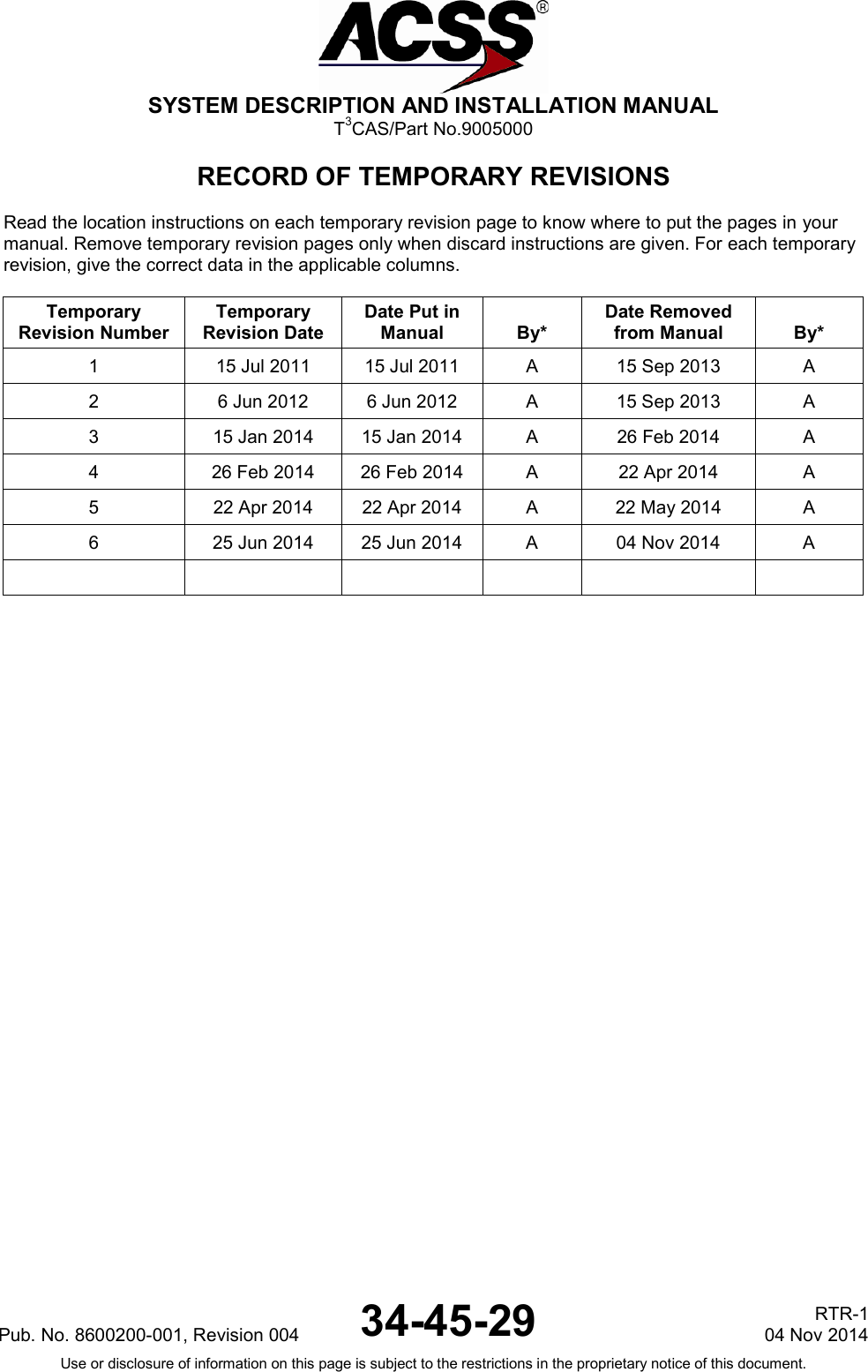

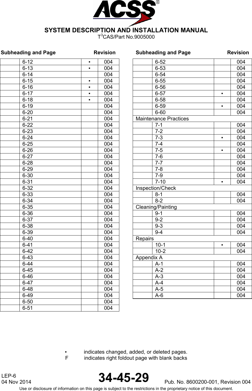
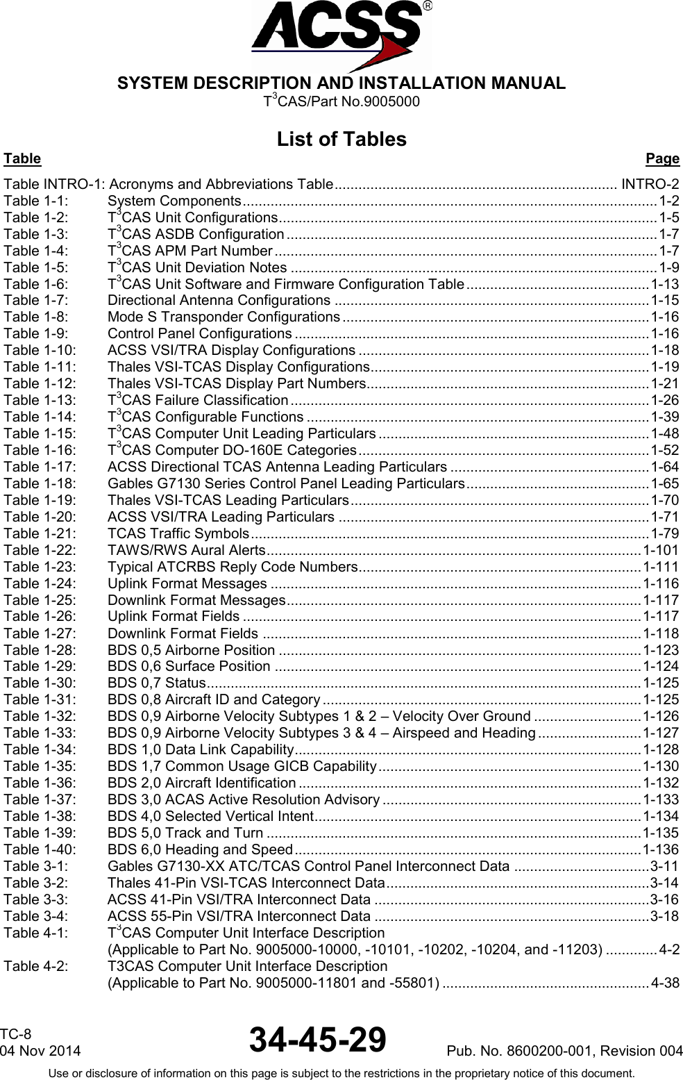
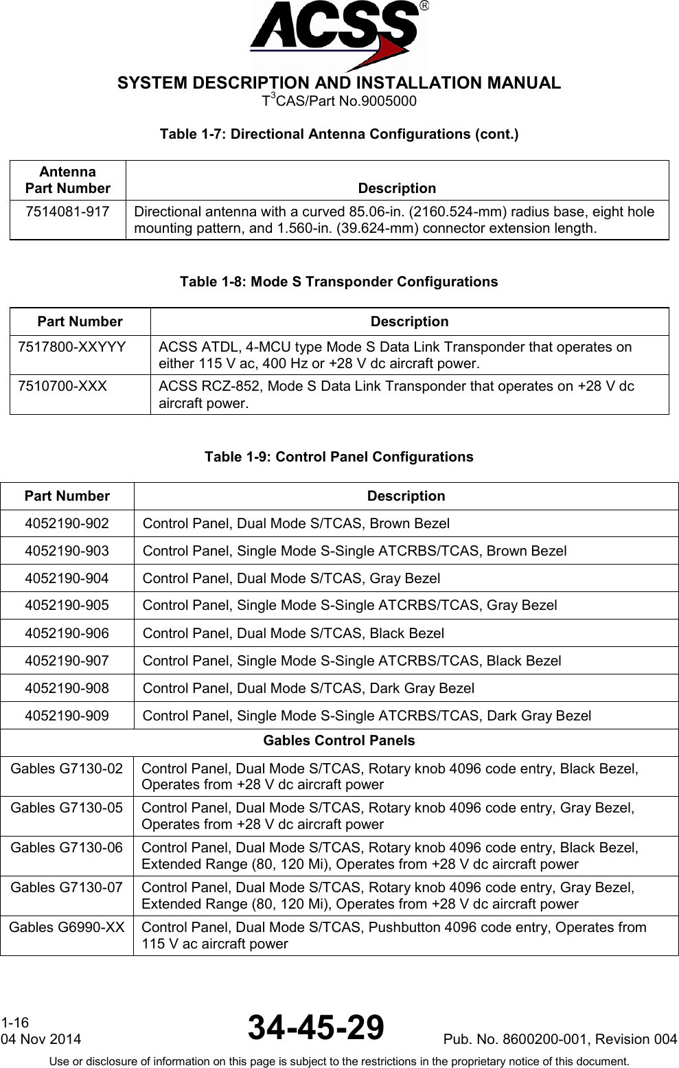
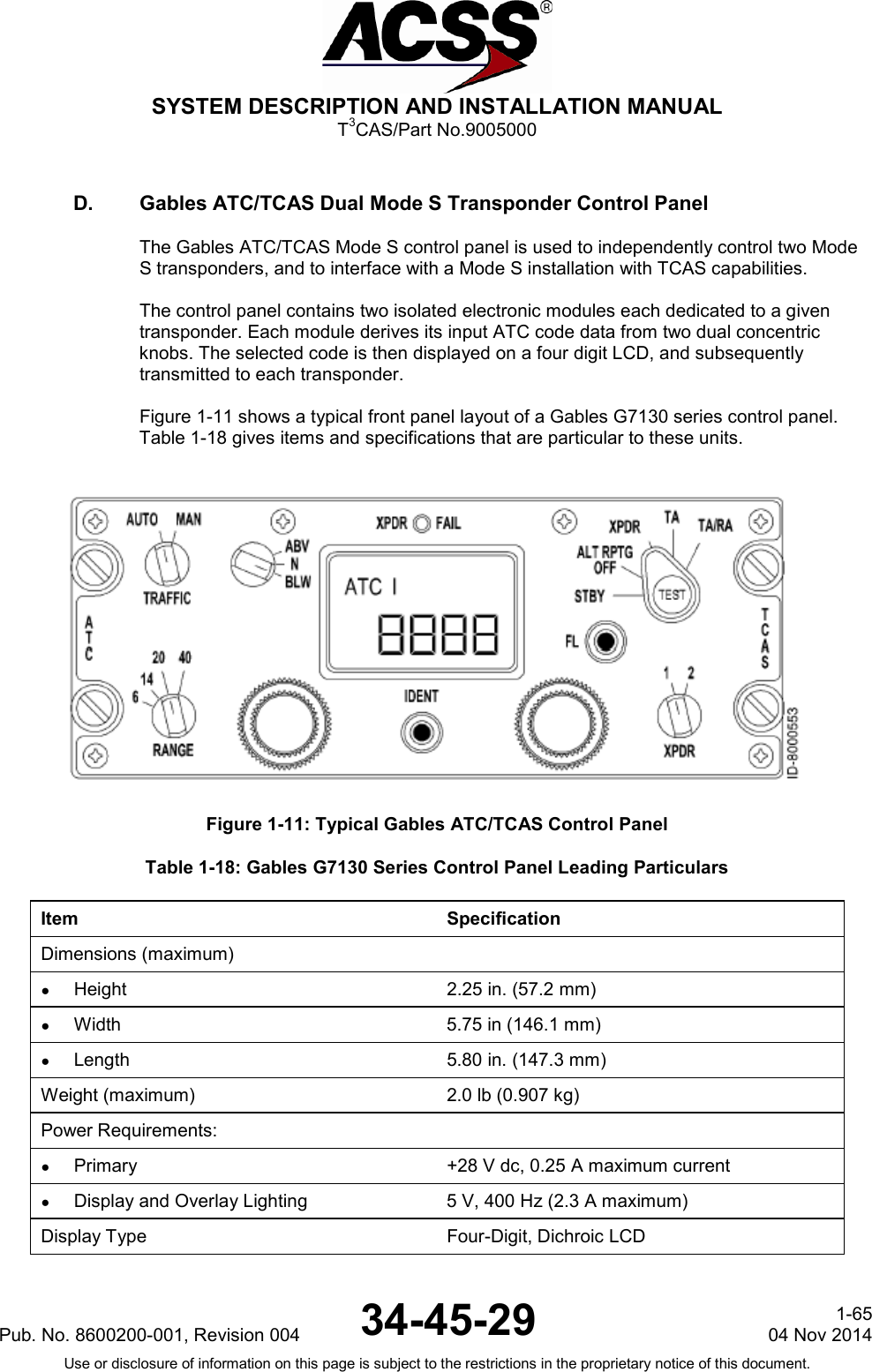
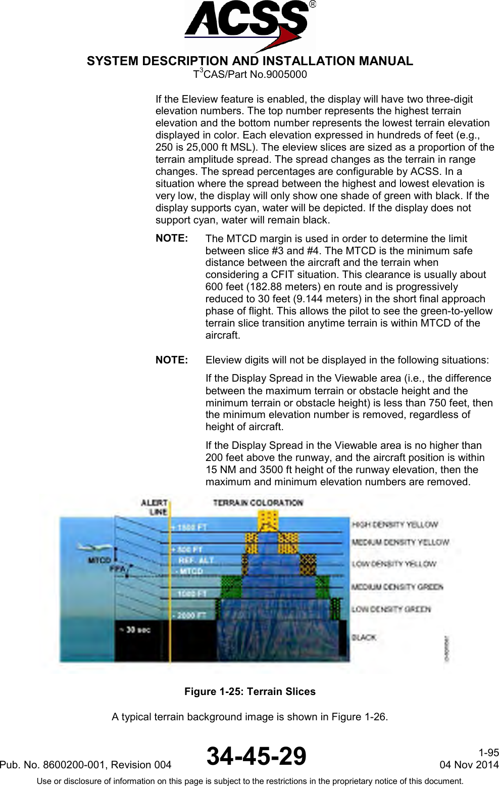
![SYSTEM DESCRIPTION AND INSTALLATION MANUAL T3CAS/Part No.9005000 Table Page Table 4-3: Gables Control Panel Interface Descriptions ................................................................. 4-71 Table 4-4: Thales 41-Pin VSI-TCAS Interface Description ............................................................. 4-73 Table 4-5: ACSS 41-Pin VSI/TRA Interface Descriptions ............................................................... 4-79 Table 4-6: ACSS 55-Pin VSI/TRA Interface Descriptions ............................................................... 4-85 Table 4-7: Callout Configuration Items (NOTE 1) ........................................................................... 4-96 Table 4-8: Operator Selectable Options – Default Settings ............................................................ 4-97 Table 4-9: Source Destination Identifier (SDI) .............................................................................. 4-109 Table 4-10: Sign Status Matrix (SSM) (BNR) .................................................................................. 4-110 Table 4-11: Sign Status Matrix (SSM) [BCD] .................................................................................. 4-110 Table 4-12: APM/ASDB Programmable Discrete Inputs (Applicable to Part Numbers 9005000-10000, -10101, -10202, -10204, -11203) ....... 4-111 Table 4-13: TAWS/XPDR Programmable Discrete Inputs (Applicable to Part Numbers 9005000-11801, -55801) ............................................... 4-114 Table 4-14: TAWS/XPDR Programmable Discrete Outputs ........................................................... 4-115 Table 4-15: T3CAS XPDR/DO-260B SPP – Input Pins (Applicable to Part Numbers 9005000-11203, -11801, -55801) .................................. 4-117 Table 4-16: T3CAS XPDR/DO-260B SPP – Output Pins (Applicable to Part Numbers 9005000-11203, -11801, -55801) .................................. 4-117 Table 4-17: DO-260B Configuration Pins (Applicable to Part Numbers 9005000-11203, -11801, -55801) .................................. 4-118 Table 4-18: DO-260B Configuration Definitions (Applicable to Part Numbers 9005000-11203, -11801, -55801) .................................. 4-119 Table 4-19: Aircraft Type Configurations ........................................................................................ 4-120 Table 4-20: Spare Configuration/Audio Test Volume/Audio Menu Selection ................................. 4-123 Table 4-21: CRT-LCD Display Select and Alternate Lamp Format ................................................ 4-124 Table 4-22: Spare Configuration/Automatic CPA/OCPA-THD/OHD Deactivation/Spare ............... 4-125 Table 4-23: Alternate Alert Priority Management/Predictive Windshear Present/ Blank Angle Function ................................................................................................... 4-126 Table 4-24: Runway Alert Function/GPS Source/Topographical Mode Function ........................... 4-127 Table 4-25: ADLP/Terr Data Comparison/Flight Function .............................................................. 4-128 Table 4-26: Lateral Position Priority/Simulator Environment .......................................................... 4-129 Table 4-27: Alternate Altitude Source Selection, Autonomous GPS Present, and Hybrid GPS Present ..................................................................................................... 4-130 Table 4-28: Maximum Cruising True Airspeed ................................................................................ 4-131 Table 4-29: Cold Temperature Compensation Function ................................................................. 4-131 Table 4-30: Terrain Advisory Line ................................................................................................... 4-132 Table 4-31: Eleview Function .......................................................................................................... 4-132 Table 4-32: Obstacle Function ........................................................................................................ 4-133 Table 4-33: Program Pin Parity ....................................................................................................... 4-133 Table 4-34: Program Pin Parity Inputs ............................................................................................ 4-134 Table 4-35: TCAS Bottom Antenna Deactivation and XPDR Top Antenna Deactivation ............... 4-134 Table 4-36: TAWS Activation and XPDR Activation Configuration ................................................. 4-135 Table 4-37 Internal Transponder SDI ............................................................................................. 4-136 Table 4-38: ATSAW (ADS-B) Parity ................................................................................................ 4-136 Table 4-39: Program Pin Parity Inputs ............................................................................................ 4-136 Table 4-40: Merging and Spacing Enable/Disable Configuration (Applicable to 9005000-10000, -10101, -10202, -10204, or -11203) .......................... 4-137 Table 4-41: Surface Area Movement Management Enable/Disable Configuration (Applicable to 9005000-10000, -10101, -10202, -10204, or -11203) .......................... 4-137 Table 4-42: In-Trail Procedures Enable/Disable Configuration (Applicable to 9005000-10000, -10101, -10202, -10204, or -11203) .......................... 4-138 Pub. No. 8600200-001, Revision 004 34-45-29 TC-9 04 Nov 2014 Use or disclosure of information on this page is subject to the restrictions in the proprietary notice of this document.](https://usermanual.wiki/ACSS-an-L-3-Communications-and-Thales/T3C-16/User-Guide-3130045-Page-27.png)
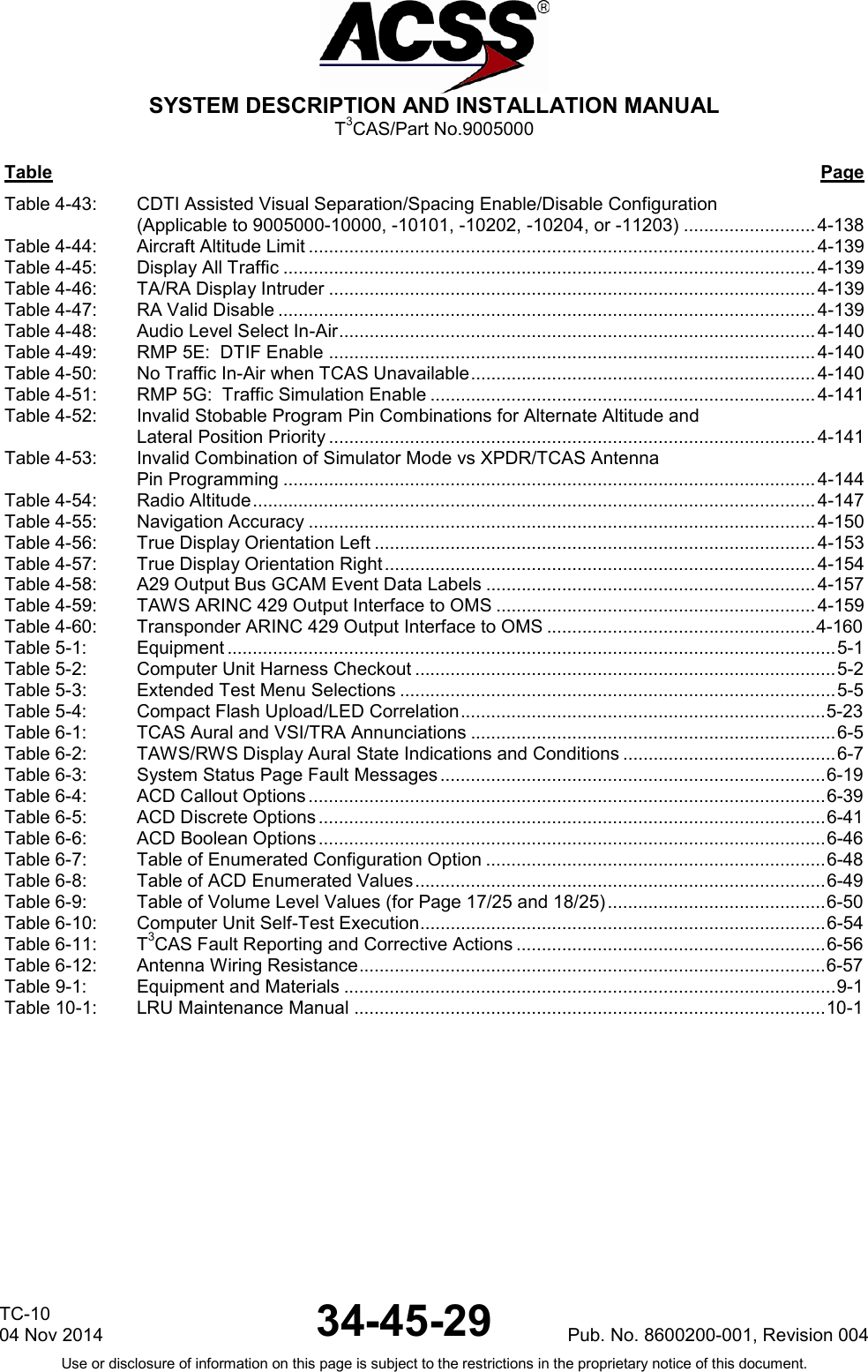
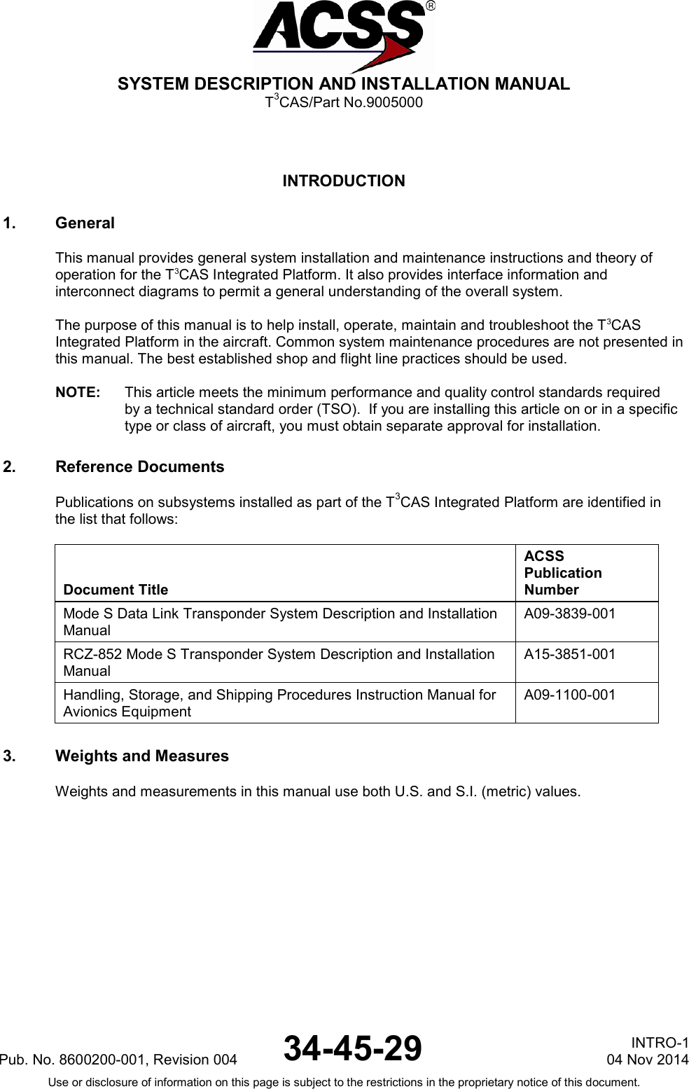

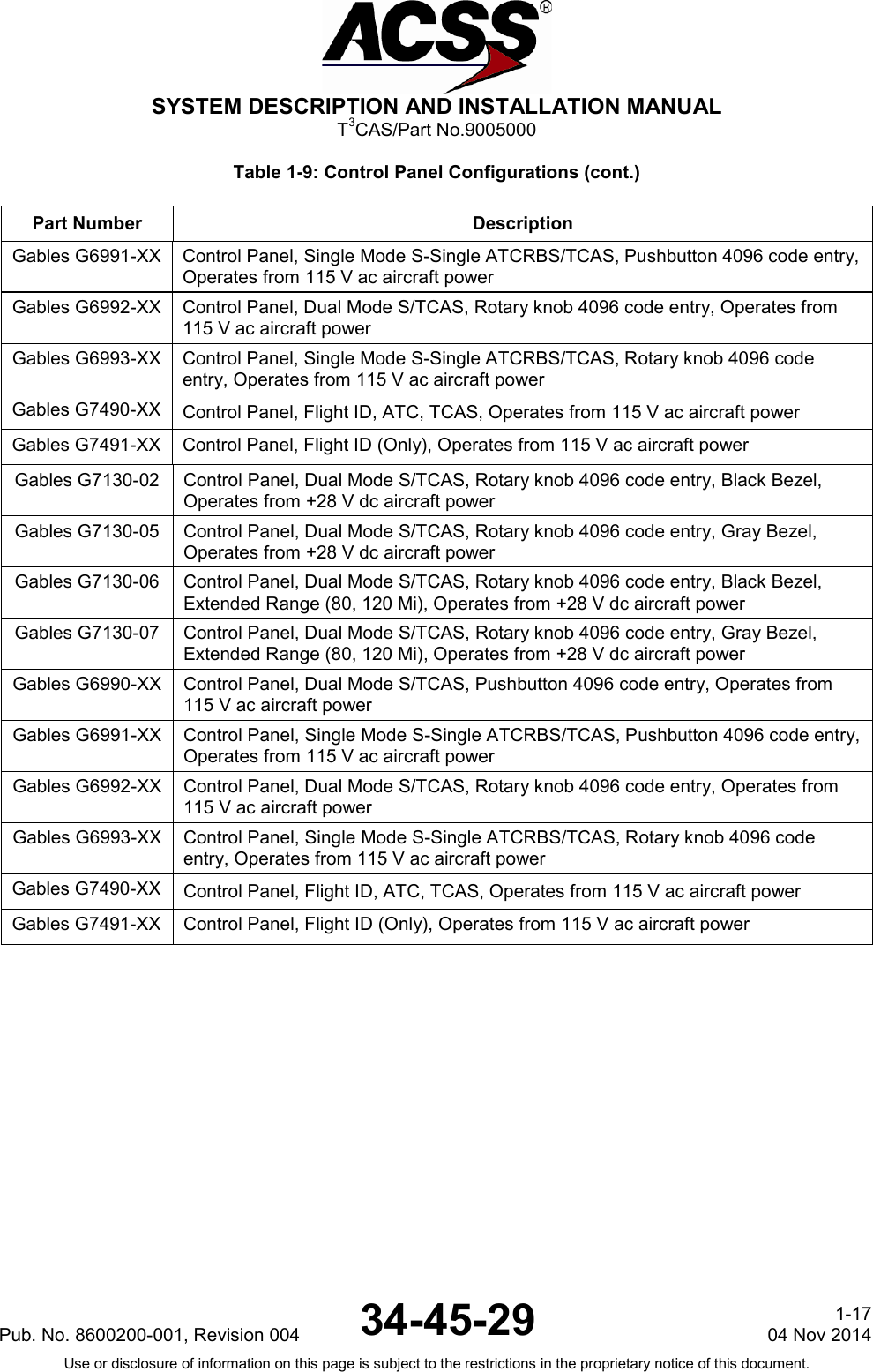
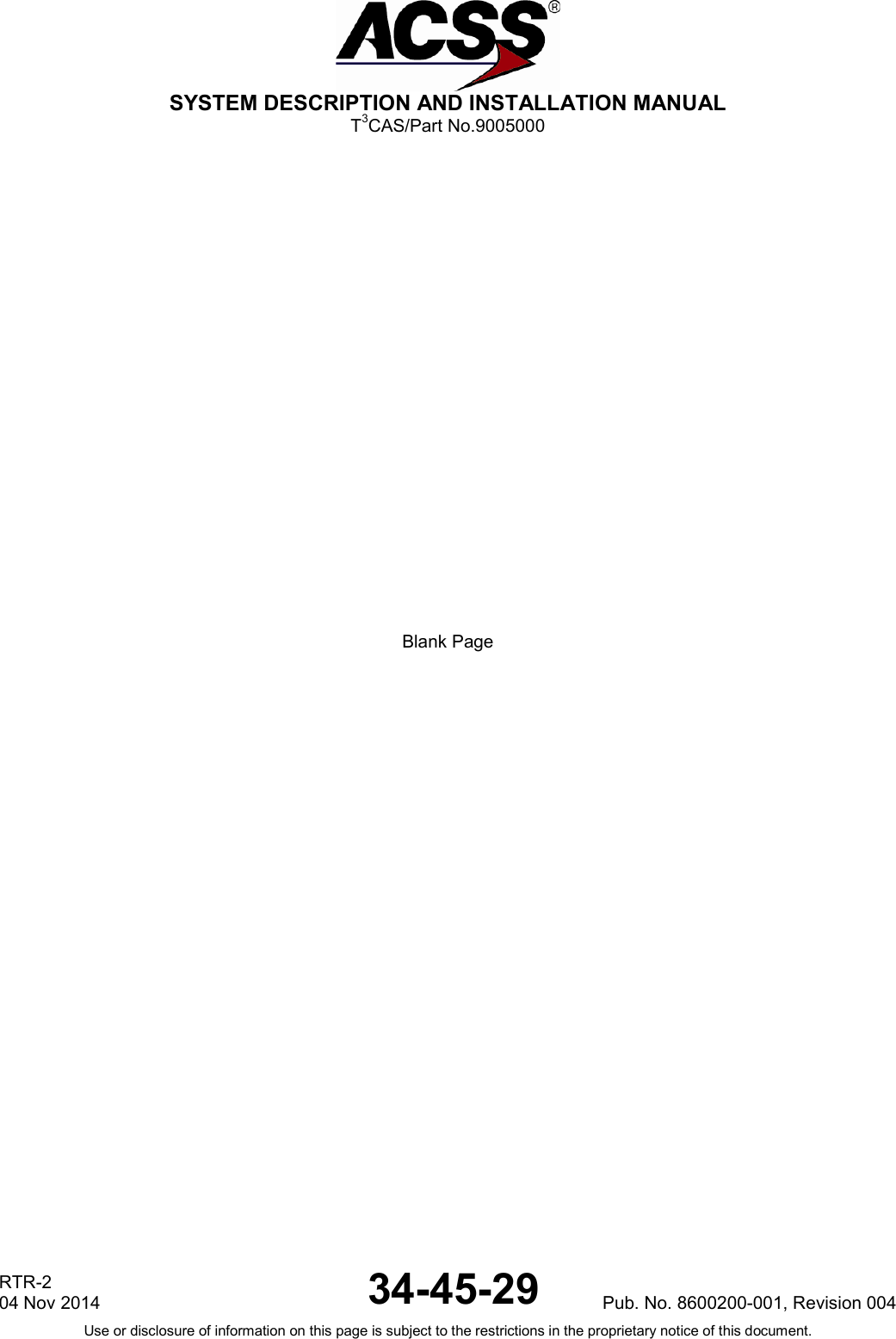
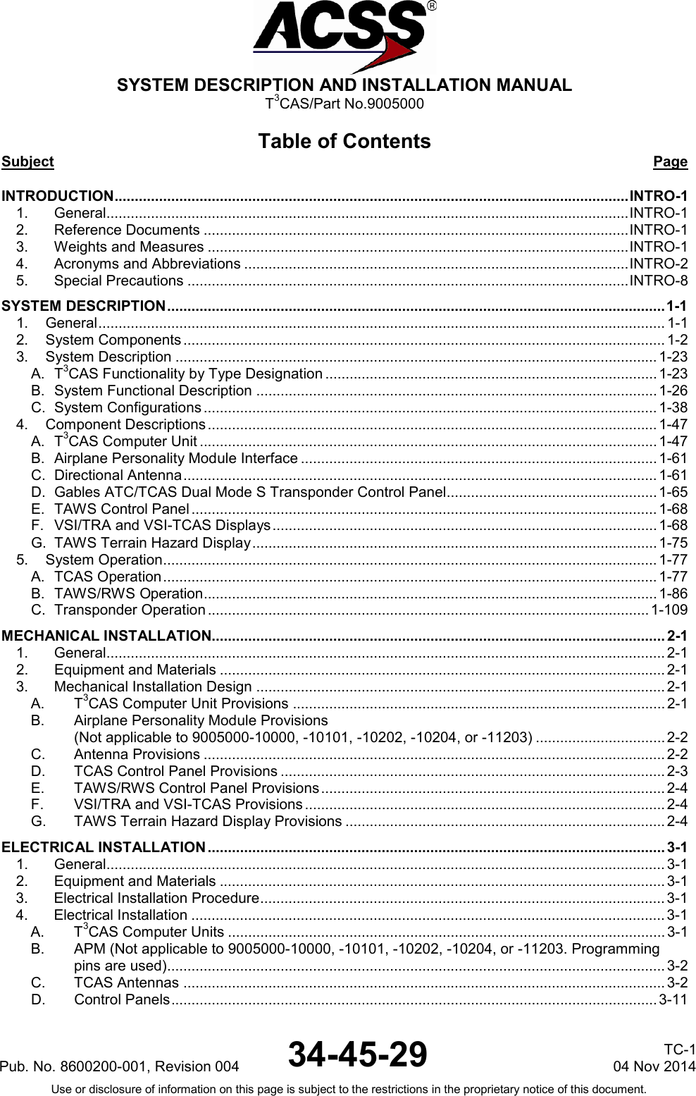
![SYSTEM DESCRIPTION AND INSTALLATION MANUAL T3CAS/Part No.9005000 Table 1-12: Thales VSI-TCAS Display Part Numbers PART NUMBER HARDWARE VERSIONS SOFTWARE VERSIONS 457400 ES GB JB HB KB PB MB RB SB TC WB FB UB ZB LA 0012 0312 0712 0812 1901 [7] 2101 [6] 1502 X X X X X X X X X X X X X EXSITING P/Ns X X X X X X X X X X X X X X X X HARDWARE OPTIONS BEZEL COLOR GREY X X X X X X X X BLACK X X X X X BROWN X X ELECTRICAL CONNECTOR RECEPTACLE 41P6 X X X X X X X X X X X (MS83723 41 PN) X X X X PRESSURE BOSS MS 33649-5 X X X X X X X X X X X X X QUICK DISCONNECT X X CONTROL BUTTONS SELECT RANGE “RNG” X OPTIONS NOT AVAILABLE X X X OPTIONS NOT AVAILABLE SELECT RANGE “-“ and “+” X X Altitude Band “A/B” X X TCAS TRAFFIC DISPLAY Full time/Part Time “ON/OFF” X X LIGHTNING FEATURES Brightness fine adjustment X Specific night luminosity law X X NVG compatible X X POWER SUPPLY 115v-400Hz X X X X X X X X X X X +28 V dc X X X X SOFTWARE OPTIONS Traffic part/full sel via ARINC X X X X X Traffic part/full sel via button X Range via ARINC 6-12 NMI X Pub. No. 8600200-001, Revision 004 34-45-29 1-21 04 Nov 2014 Use or disclosure of information on this page is subject to the restrictions in the proprietary notice of this document.](https://usermanual.wiki/ACSS-an-L-3-Communications-and-Thales/T3C-16/User-Guide-3130045-Page-58.png)
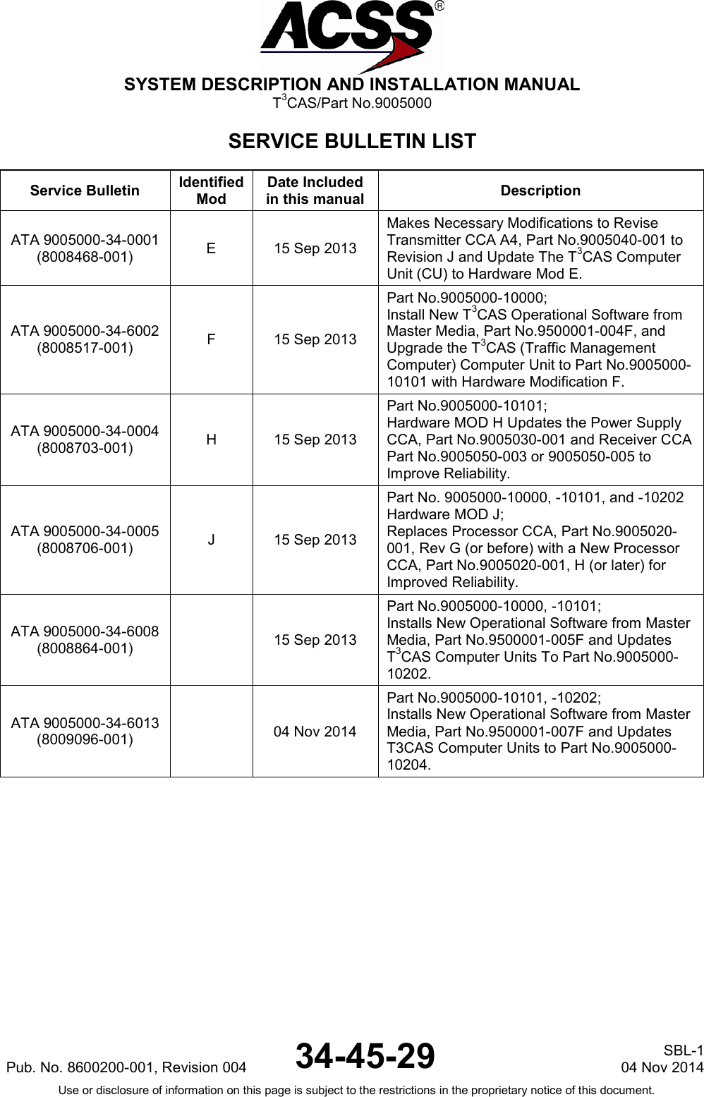
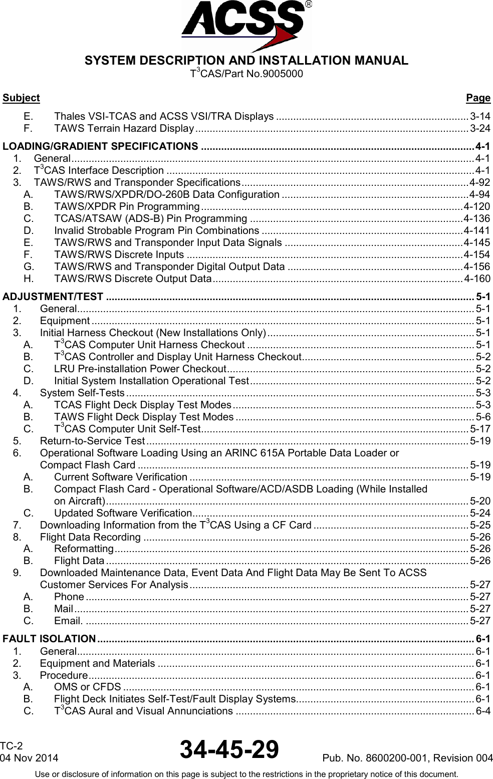
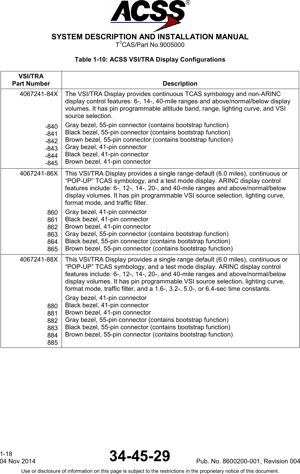
![SYSTEM DESCRIPTION AND INSTALLATION MANUAL T3CAS/Part No.9005000 Table 1-12: Thales VSI-TCAS Display Part Numbers PART NUMBER HARDWARE VERSIONS SOFTWARE VERSIONS Range via ARINC 3-5-10 NMI Range via ARINC 6-12-24 NMI X Range via ARINC 3, 5, 6, 10, 12, 14, 15, 20, 40, 80, 120 NMI X Range via button 6-12 NMI X X Range via button 4-8-16 NMI X Range via ARINC 5-10-20 NMI X (1) Range via ARINC 5, 6, 10, 12, 20, 40 NMI X (1) X (1) ABV/NORN/BLW via ARINC X X X X X X ABV/NORN/BLW via button X Absolute altitude via ARINC X X X X X Vertical Speed in metric units (M/S) X TCAS Extended Test normal X X X X X X TCAS Extended Test normal + text display mode X X Specific Symbology (2) (3) (4) (5) Note [1] Only when instrument is pin-programmed for operation in TCAS TRAFFIC DISPLAY only [2] Specific symbology for “don’t climb” and “don’t descend” RA’s, V/S failure with background instead of yellow [3] V/S pointer shorter and thicker. Traffic range version 8 NMI when in TCAS self-test. [4] ABV (above) or BLW (below) message on the display when one of these modes are selected by A/B push-button on bezel [5] This version is only for TCAS 1 operation (no RA DISPLAY, TCAS validity discrete output is relative to Traffic instead of RA, No ABV/BLW message displayed [6] Dedicated software for ACSS (formerly Honeywell) [7] This SW version replaces the previous version “1311”, “1312”, “0911”, “1100” and “2000” 1-22 04 Nov 2014 34-45-29 Pub. No. 8600200-001, Revision 004 Use or disclosure of information on this page is subject to the restrictions in the proprietary notice of this document.](https://usermanual.wiki/ACSS-an-L-3-Communications-and-Thales/T3C-16/User-Guide-3130045-Page-59.png)
![SYSTEM DESCRIPTION AND INSTALLATION MANUAL T3CAS/Part No.9005000 and airlines. The T3CAS Transponder function interfaces to all commonly used Mode S and Mode S/TCAS control panels. The T3CAS Transponder function has a dedicated low-speed ARINC 429 data input for receiving the Aircraft Identification Subfield (AIS) Flight Identification from another aircraft system (i.e., a Flight Management System [FMS] or Onboard Maintenance System [OMS]). The flight ID can also be received on DAPS busses (high- or low-speed) or from the control panel on the control data bus (low-speed). The flight identification can be the aircraft flight number or tail number. (e) Discrete Interfaces and Configuration Interfaces The T3CAS Transponder function has discrete inputs for configuration and control of Mode S Transponder functions and interfaces, and discrete outputs for annunciating transponder status information. The T3CAS Transponder function implements the discrete inputs and outputs defined by ARINC 718. The input/output discretes default to an open state when power is removed. (f) Maintenance Computer Interface The T3CAS Transponder function has a maintenance computer interface that allows maintenance and test data and histories to be obtained from the unit while it is installed in an aircraft. The transponder interfaces with maintenance systems for all major airframes via low-speed ARINC 429 input and output data busses. (g) Navigation Data ARINC 429 Interface The T3CAS Transponder function has ARINC 429 input bus circuitry for extended squitter and enhanced DAPS capability. The transponder meets ELS/EHS requirements. Pub. No. 8600200-001, Revision 004 34-45-29 1-37 04 Nov 2014 Use or disclosure of information on this page is subject to the restrictions in the proprietary notice of this document.](https://usermanual.wiki/ACSS-an-L-3-Communications-and-Thales/T3C-16/User-Guide-3130045-Page-74.png)
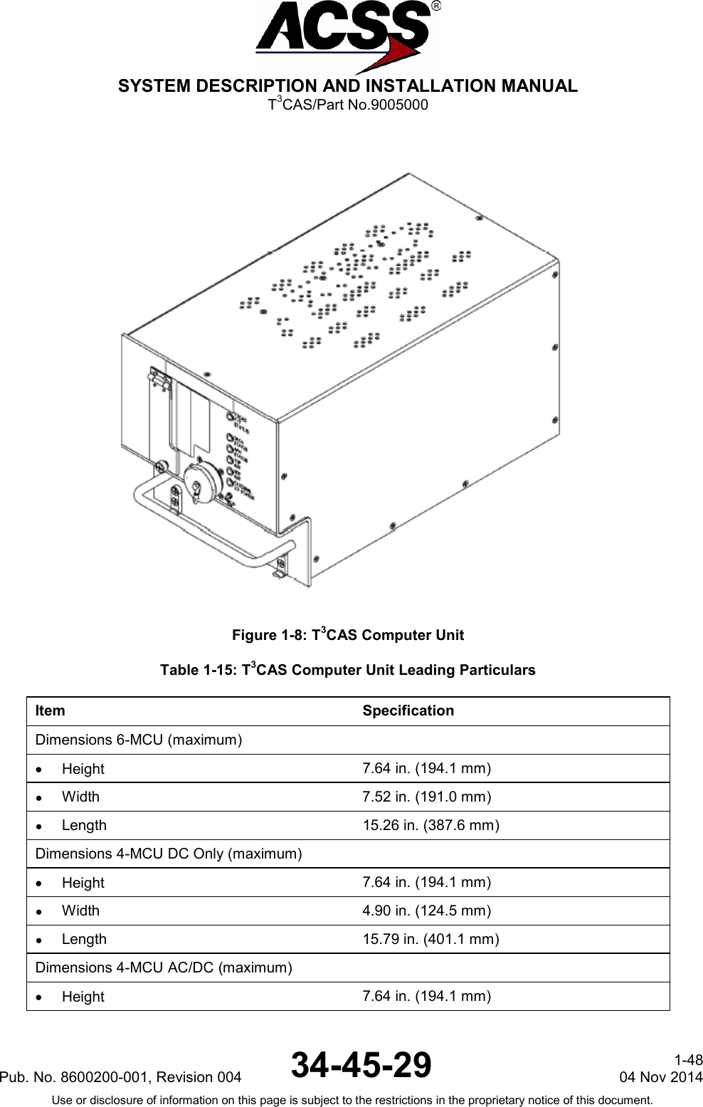
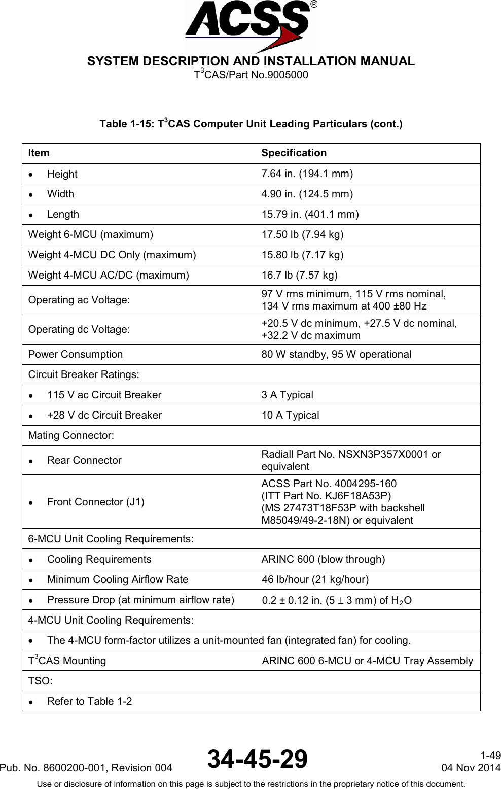
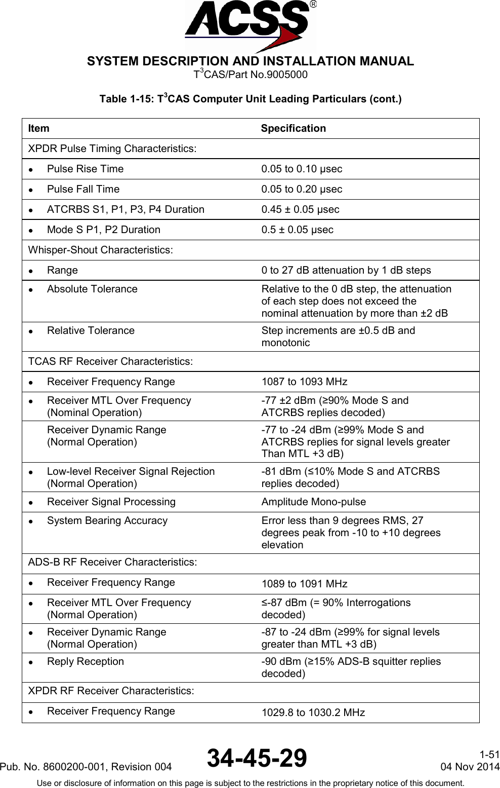
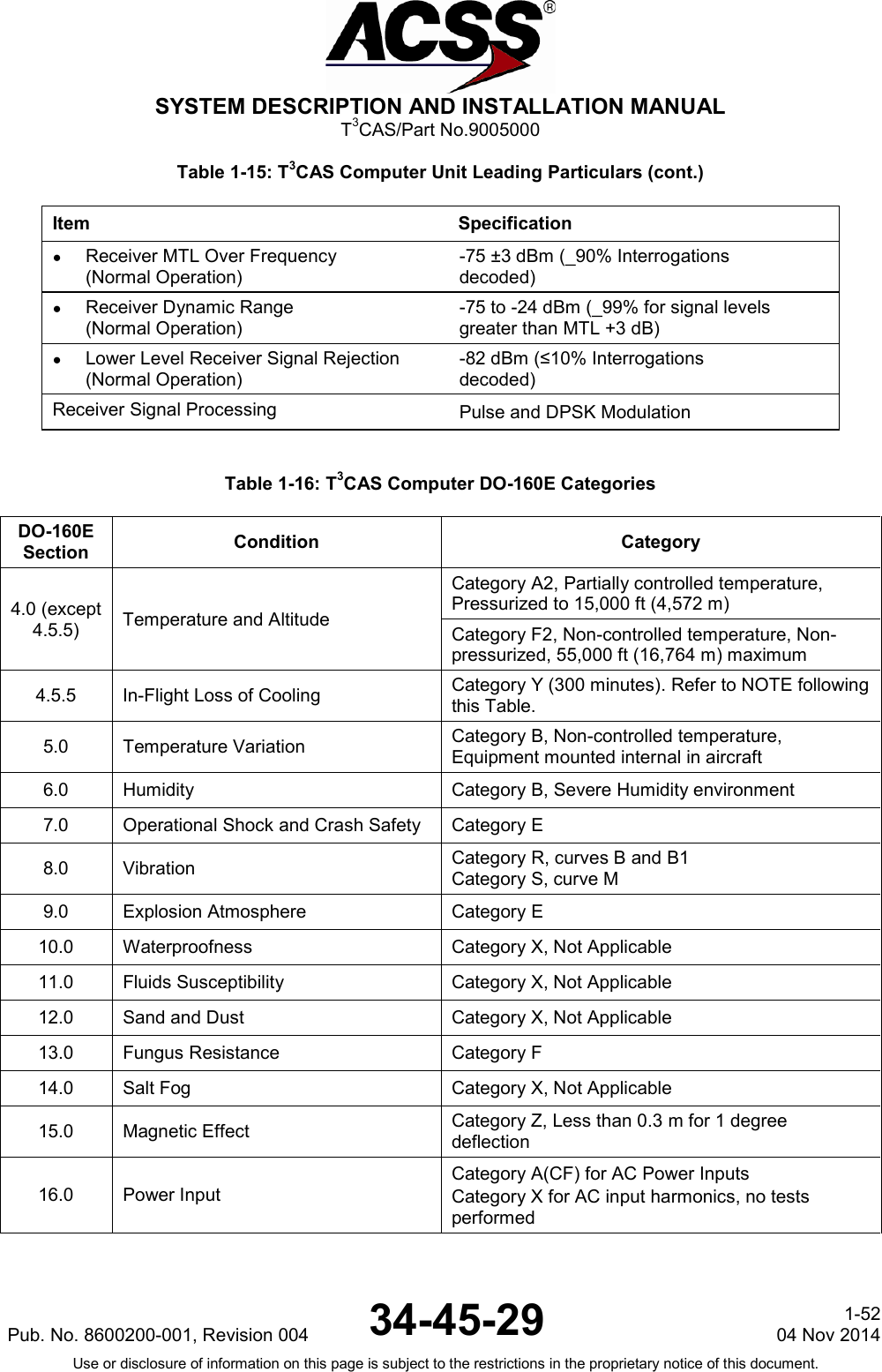
![SYSTEM DESCRIPTION AND INSTALLATION MANUAL T3CAS/Part No.9005000 Table 1-15: T3CAS Computer Unit Leading Particulars (cont.) Item Specification ● Software Development Specification DO-178B, Level B ● Environmental Specifications Applicable to 9005000-10000, -10101, -10202, -10204, -11203, -11801, and -55801. DO-160E Refer to Table 1-16 Temperature/Altitude [A2F2]: ● Operating Temperature -55 to +70 degrees C (-67 to 158 degrees F) ● Ground Survival Temperature -55 to +85 degrees C (-67 to 185 degrees F) ● Altitude Sea Level to 55,000 ft (16764 m) ● Loss of Cooling +40 degrees C (+104 degrees F) for 18 hours minimum RF Transmitter Characteristics: ● Unwanted Output Power in an Inactive State -79 dBm (960-1215 MHz) ● TCAS Transmitter Frequency 1030 ± 0.01 MHz TCAS RF Peak Output Power: ● Minimum 53.5 dBm (224 W) ● Nominal 54.0 dBm (251 W) ● Maximum 57.5 dBm (562 W) XPDR Transmitter Frequency 1090 ± 0.01 MHz XPDR/ADS-B RF Peak Output Power (each port of directional antenna): ● Minimum 51.4 dBm (138 W) ● Nominal 52.2 dBm (166 W) ● Maximum 55.4 dBm (347 W) TCAS Pulse Timing Characteristics: ● Pulse Rise Time 0.05 to 0.10 µsec ● Pulse Fall Time 0.05 to 0.20 µsec ● ATCRBS S1, P1, P3, P4 Duration 0.8 ± 0.05 µsec ● Mode S P1, P2 Duration 0.08 ± 0.05 µsec ● Mode S P6 Duration 16.25 ± 0.125 µsec (short) 30.25 ± 0.125 µsec (long) Pub. No. 8600200-001, Revision 004 34-45-29 1-50 04 Nov 2014 Use or disclosure of information on this page is subject to the restrictions in the proprietary notice of this document.](https://usermanual.wiki/ACSS-an-L-3-Communications-and-Thales/T3C-16/User-Guide-3130045-Page-87.png)
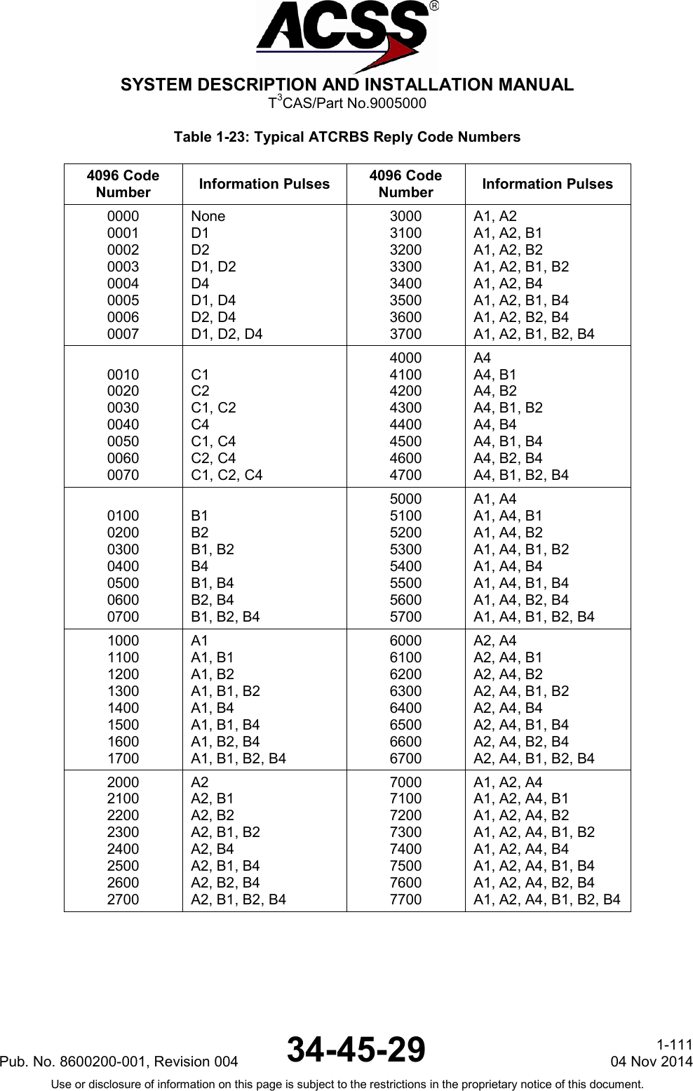
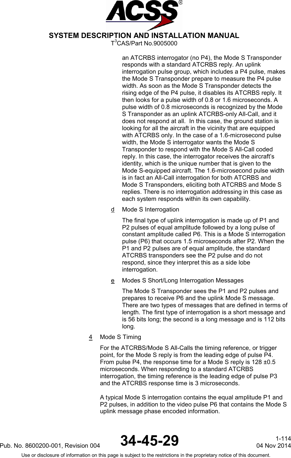
![SYSTEM DESCRIPTION AND INSTALLATION MANUAL T3CAS/Part No.9005000 2 Air to Air Communication Traffic Alert and Collision Avoidance System and Mode S Transponders are an integral part of the Traffic Alert and Collision Avoidance System (TCAS). TCAS-equipped aircraft are airborne interrogators, communicating with other TCAS-equipped aircraft through their Mode S Transponders for coordination of collision avoidance maneuvers. TCAS aircraft acquire other Mode S Transponder-equipped aircraft by receiving squitter transmissions (unsolicited All-Call type replies, transmitted pseudo-randomly every 0.8 to 1.2 seconds), and thereafter by special addressed interrogations. Although either Mode S or ATCRBS Mode C Transponders aid TCAS-equipped aircraft in avoiding collisions, coordination of collision avoidance maneuvers is possible between two aircraft only if both are Mode S and TCAS equipped. 3 Mode S Messages a Interrogation and Reply Formats Mode S features have been added to the ATCRBS already in place. This procedure ensures that the older airborne transponders and the ground-based interrogators used in the ATCRBS are still functional. The Mode S signal formats used for this combined system operation are ATCRBS/Mode S All-Call [Mode A and Mode C], Mode S interrogation, Mode S SLS, and Mode S reply. b Interrogation Pulses and Timing The uplink Mode S format for the interrogation pulse group consists of pulses designated P1, P2, and P3. The time spacing between the P1 and P3 pulses determines the type of interrogation (Mode A aircraft identification or Mode C altitude reporting). Pulse P2, which follows P1 by 2 microseconds, is used for Side Lobe Suppression (SLS) in the ATCRBS. The amplitude of P2 is recognized by the airborne transponder as either a main beam or SLS interrogation. With Mode S interrogation, the basic P1 and P3 pulse system is extended to include a P4 pulse, which follows P3 by 2 microseconds. The P4 pulse uses the same spacing as between P1 and P2. However, P4 has an additional feature in that its pulse width can be either 1.6 microseconds or 0.8 microseconds, whereas the P1 and P3 pulse widths are always 0.8 microseconds. c Replies to All-Call Interrogations and Pulse Width In operation, when a standard ATCRBS Transponder receives this interrogation of P1, P3, and P4 pulses, it responds with the ATCRBS reply, which consists of 14 pulses that carry the identity code or the altitude code. The P4 pulse is ignored since the ATCRBS Transponder circuit is designed so that it does not recognize the P4 pulse. The response is dependent upon the presence and length of P4. When a standard P1 and P3 interrogation is received from Pub. No. 8600200-001, Revision 004 34-45-29 1-113 04 Nov 2014 Use or disclosure of information on this page is subject to the restrictions in the proprietary notice of this document.](https://usermanual.wiki/ACSS-an-L-3-Communications-and-Thales/T3C-16/User-Guide-3130045-Page-150.png)
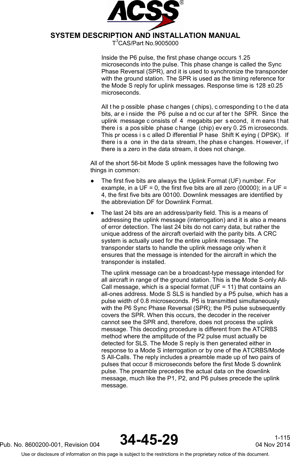
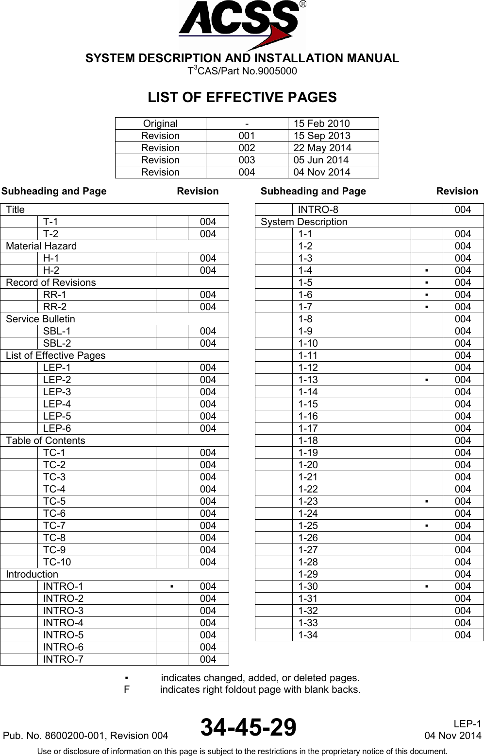
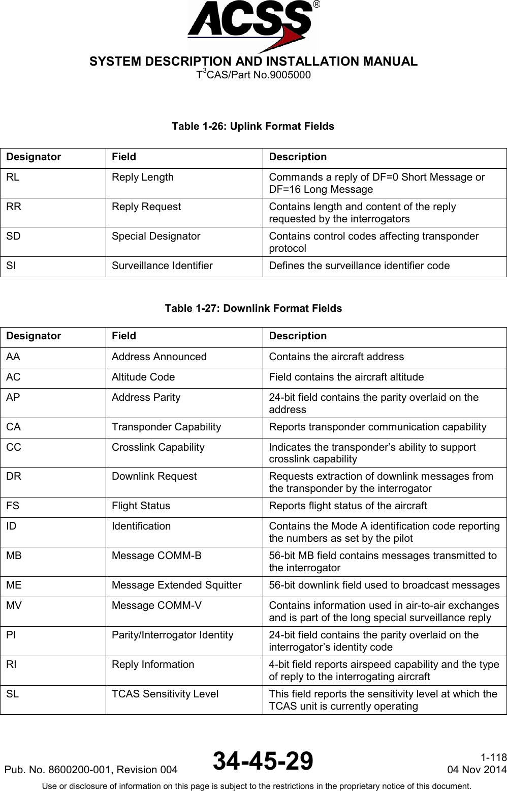
![SYSTEM DESCRIPTION AND INSTALLATION MANUAL T3CAS/Part No.9005000 There are two fundamental differences between the uplink message and the downlink message, as follows: ● The uplink burst is at 4 megabits per second, while the downlink is at 1 megabit per second. ● The uplink uses DPSK, while the downlink uses Pulse Position Modulation (PPM). Using PPM, there is one pulse for every bit, either in the first half or the second half of the bit interval (window). The first half of the window represents a 1; the second half of the window represents a 0. The reply delay time for Mode S is 128 microseconds with respect to the P6 SPR. This is true for both long and short messages. However, the downlink message data cannot be prepared until the uplink message is complete. There is an additional derived timing specification that indicates how much time is available from the end of an interrogation until the reply starts. For a short message, it is 113 microseconds; for a long message, it is 99 microseconds. The basic Mode S transponder handles only the short messages, but this timing shows that a data link transponder, which handles long messages, has more data to process and a shorter time to prepare the message. (2) Mode S Message Format and Data Field Descriptions Refer to RTCA DO-181C, DO-185, DO-218B and DO-260 for further details of Mode S Message Formats and Field definitions. Table 1-24 defines the Mode S interrogation UF (Uplink Format) messages and Table 1-25 defines the Mode S reply DF (Downlink Format) messages. The first 5 bits of the message indicate the UF/DF type. The message structure including the number of bits per subfield is included in Table 1-24 and Table 1-25. For example, UF=0 [Binary 00000] is composed of X:3 (3 bits assigned as padding), RL:1 (1 bit assigned to Reply Length) etc. The Uplink Format message field descriptions are listed in Table 1-26 and the Downlink Format message field descriptions are listed in Table 1-. Table 1-24: Uplink Format Messages Uplink Format Field Description Message Format with Number of Bits UF=0 [00000] Short Air-Air Surveillance X:3, RL:1, X:4, AQ:1, DS:8, X:10 AP:24 X:Pad UF=4 [00100] Surveillance, Altitude Request PC:3, RR:5, DI:3, SD:16, AP:24 UF=5 [00101] Surveillance, Identity Request PC:3, RR:5, DI:3, SD:16, AP:24 UF=11 [01011] Mode S Only All-Call PR:4, II/IC:4, CL:3, X:16, AP:24 X:Pad UF=16 [10000] Long Air-Air Surveillance X:3, RL:1, X:4, AQ:1, X:18, MU:56, AP:24 X:Pad UF=20 [10100] Comm-A, Altitude Request PC:3, RR:5, DI:3, SD:16, MA:56, AP:24 UF=21 [10101] Comm-A, Identity Request PC:3, RR:5, DI:3, SD:16, MA:56, AP:24 NOTE: PC, RR, DI and SD subfields are undefined for UF=20/21 broadcast interrogations. Pub. No. 8600200-001, Revision 004 34-45-29 1-116 04 Nov 2014 Use or disclosure of information on this page is subject to the restrictions in the proprietary notice of this document.](https://usermanual.wiki/ACSS-an-L-3-Communications-and-Thales/T3C-16/User-Guide-3130045-Page-153.png)
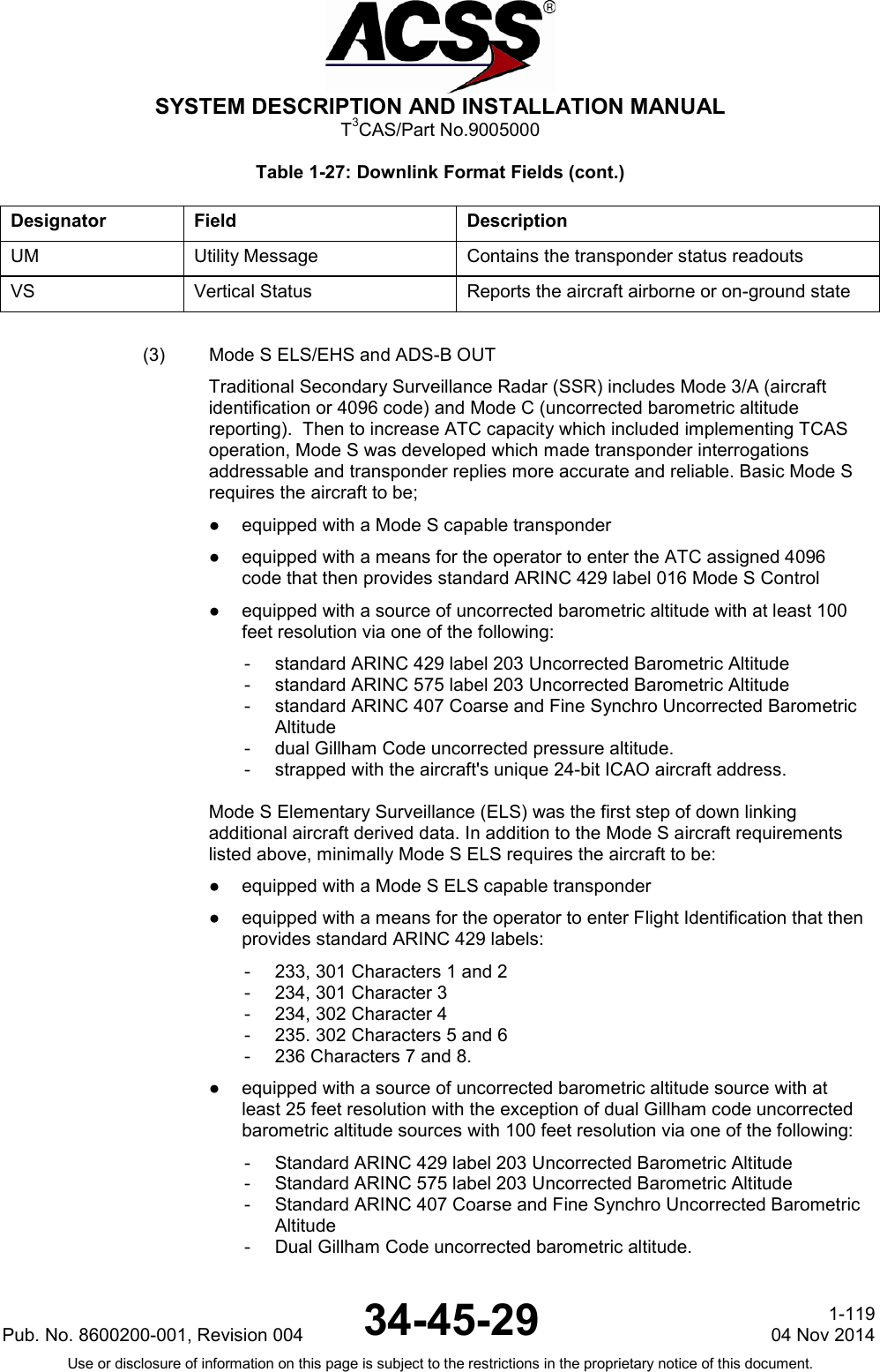
![SYSTEM DESCRIPTION AND INSTALLATION MANUAL T3CAS/Part No.9005000 Table 1-25: Downlink Format Messages Downlink Format Field Description Message Format with Number of Bits DF=0 [00000] Short Air-Air Surveillance VS:1, CC:1, X:1, SL:3, X:2, RI:4, X:2, AC:13, AP:24 X:Pad DF=4 [00100] Surveillance, Altitude Reply FS:3, DR:5, UM:6, AC:13, AP:24 DF=5 [00101] Surveillance, Identity Reply FS:3, DR:5, UM:6, ID:13, AP:24 DF=11 [01011] All-Call Reply CA:3, AA:24, PI:24 DF=16 [10000] Long Air-Air Surveillance VS:1, X:2, SL:3, X:2, RI:4, X:2, AC:13, MV:56, AP:24 X:Pad DF=17 [10001] Extended Squitter (ADS-B) CA:3, AA:24, ME:56, PI:24 DF=20 [10100] Comm-B, Altitude Reply FS:3, DR:5, UM:6, AC:13, MB:56, AP:24 DF=21 [10101] Comm-B, Identity Reply FS:3, DR:5, UM:6, ID:13, MB:56, AP:24 Table 1-26: Uplink Format Fields Designator Field Description AP Address Parity 24-bit discrete address with parity check bits overlaid AQ Acquisition Designates formats UF=0, 16 as acquisition transmissions or non-acquisition. CL Code Label Identifies the contents of the IC field DI Designator Identification Identifies the coding contained in the SD field DS COMM-B Data Selector Contains the identity of the ground-initiated COMM-B register IC Interrogator Code Contains either the II Code or SI Code II Interrogator Identification Identifies the interrogator MA Message COMM-A 56-bit uplink field contains messages directed to the aircraft MU Message COMM-U 56-bit uplink field contains information used in air-to-air exchanges part of the long special surveillance interrogation NC Number of C Segments Number of segments transmitted in ELM mode and part of a COMM-C interrogation PC Protocol Operating commands to the transponder PR Probability of Reply Contains commands to the transponder which specify the reply probability to the Mode S only All-Call interrogations RC Reply Control Designates the transmitted segment as initial, intermediate or final Pub. No. 8600200-001, Revision 004 34-45-29 1-117 04 Nov 2014 Use or disclosure of information on this page is subject to the restrictions in the proprietary notice of this document.](https://usermanual.wiki/ACSS-an-L-3-Communications-and-Thales/T3C-16/User-Guide-3130045-Page-154.png)

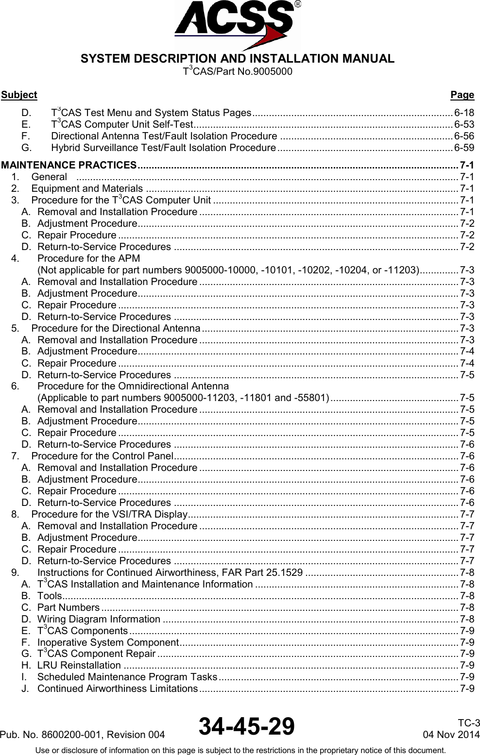
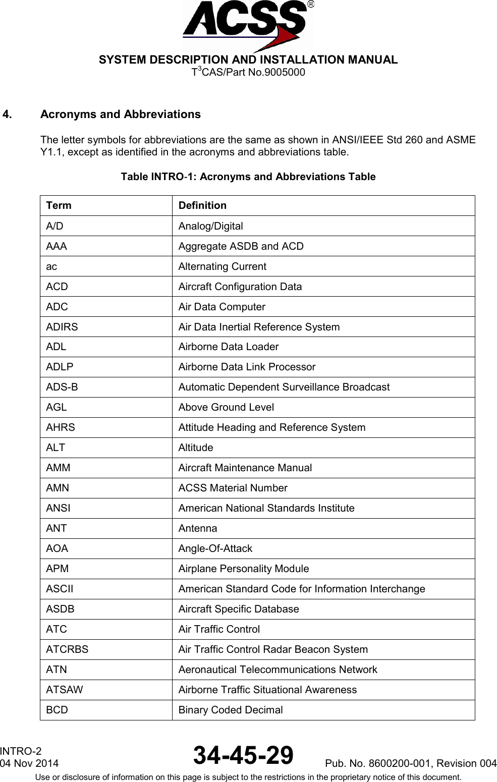
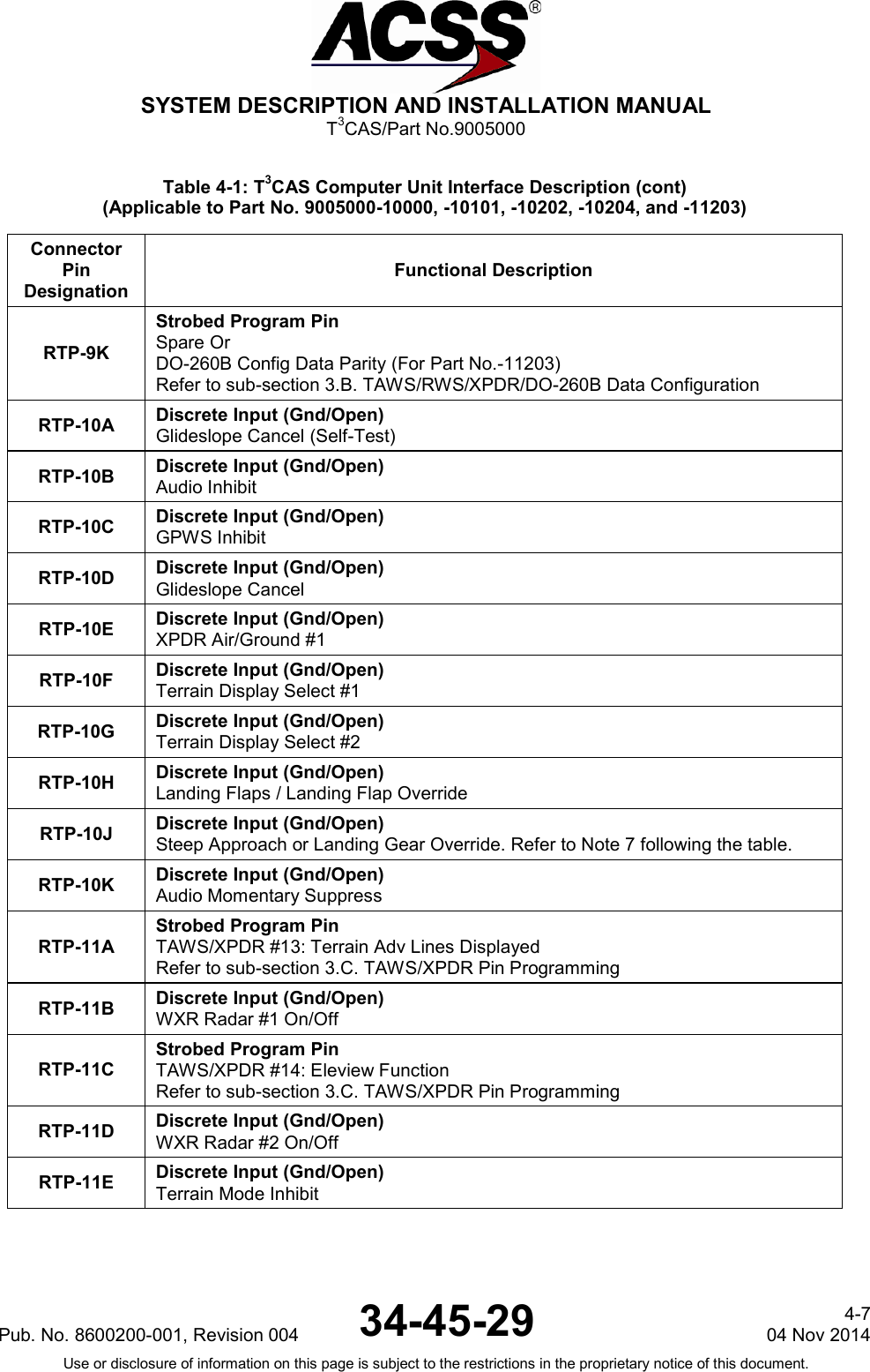
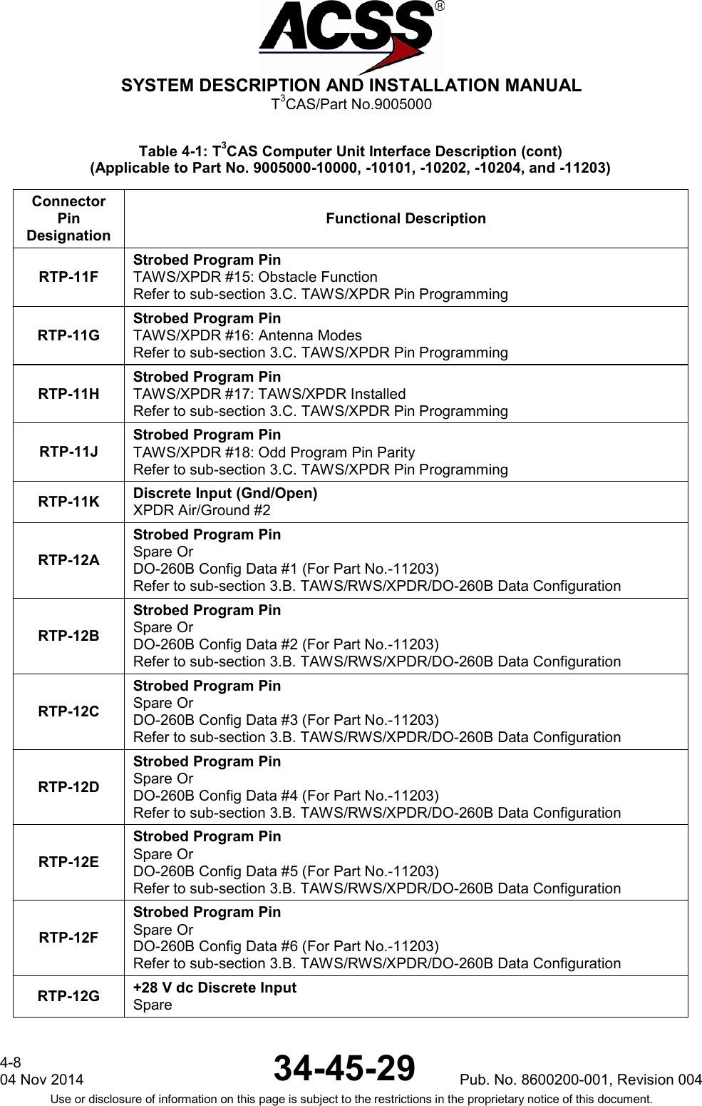
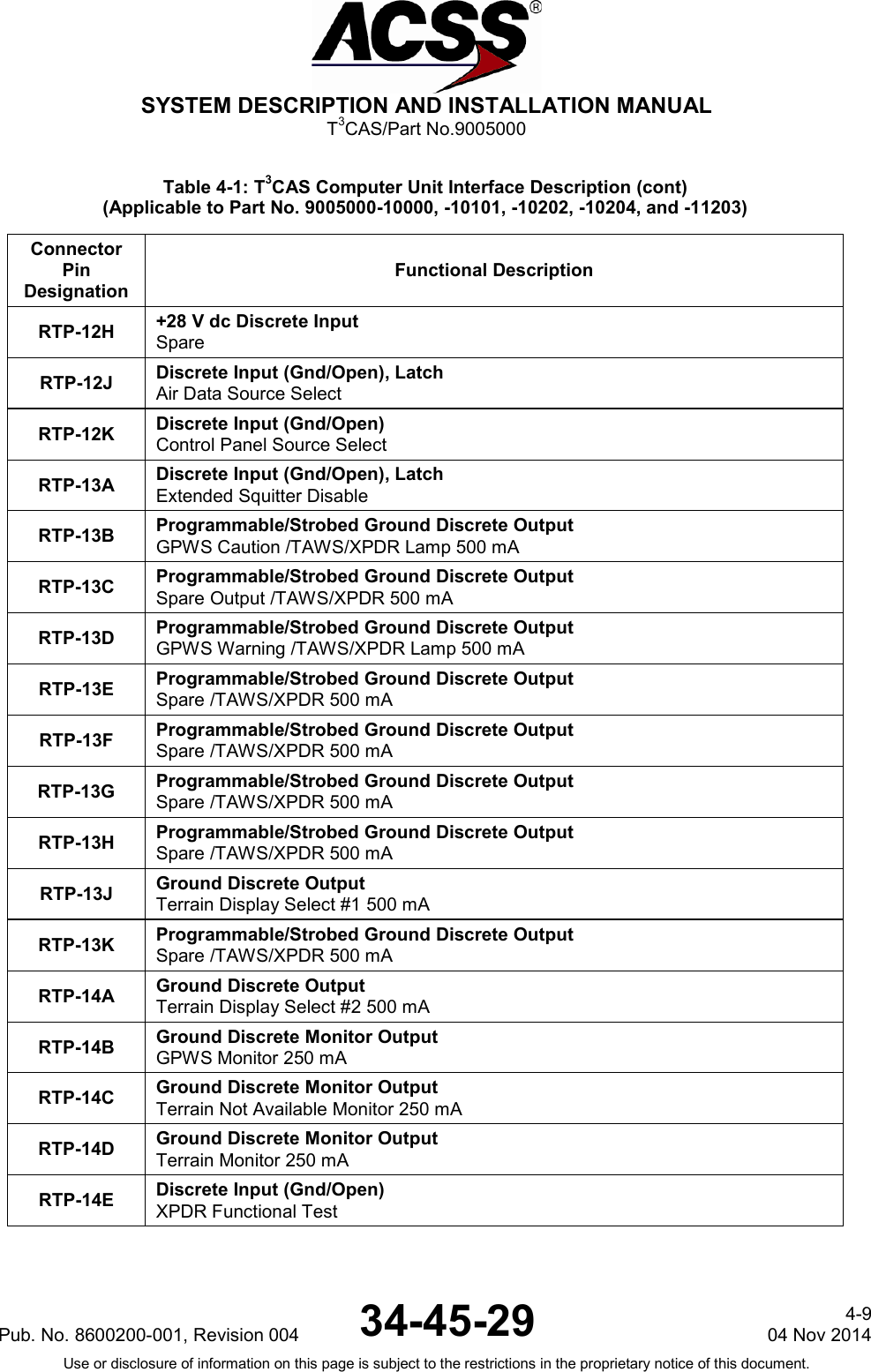
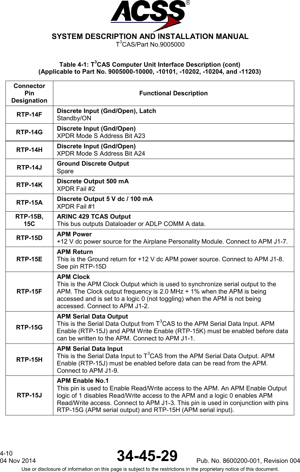
![SYSTEM DESCRIPTION AND INSTALLATION MANUAL T3CAS/Part No.9005000 Table 4-1: T3CAS Computer Unit Interface Description (Applicable to Part No. 9005000-10000, -10101, -10202, -10204, and -11203) Connector Pin Designation Functional Description T3CAS Computer Unit Right Top Plug (RTP) RTP-1A, 1B ARINC 453 Terrain Display Output No.1 (CAPT): (RTP-1A [A], RTP-1B [B]) T3CAS output number 1 to the terrain awareness display. RTP-1C, 1D ARINC 429 Input: MMR/GPS #1 [RTP-1C (A), RTP-1D (B)] This high-speed 429 input is used to receive GPS label input containing position, velocity and quality information for the use of ADS-B IN applications and by the transponder function of ADS-B OUT. NOTE: These pins are designated for MMR/GPS #1 if T3CAS is operating as TAWS and TCAS only with internal transponder and ATSAW function disabled. Else these pins are Spares. RTP-1E, 1F ARINC 453 Terrain Display Output No.2 (F/O): (RTP-1E [A], RTP-1F [B]) T3CAS output number 2 to the terrain awareness display. RTP-1G, 1H ARINC 429 Input: FMC #1:EIS [RTP-1G (A), RTP-1H (B)] This high-speed 429 input from the Flight Management Computer (FMC) Electronic Instrument System (EIS) provides position information from the FMC to the T3CAS. NOTE: These pins are designated for FMC #1 if T3CAS is operating as TAWS and TCAS only with internal transponder disabled. Else these pins are Spares. RTP-1J, 1K ARINC 429 Input: ADIRU #2 / ADR [RTP-1J (A), RTP-1K (B)] This low-speed 429 input from the Air Data/Inertial Reference Unit (ADIRU) #2 provides altitude, airspeed, altitude rate and temperature information to the T3CAS. RTP-2A, 2B ARINC 429 Input: ADIRU #3 / ADR [RTP-2A (A), RTP-2B (B)] This low-speed 429 input from the Air Data/Inertial Reference Unit (ADIRU) #2 provides altitude, airspeed, altitude rate and temperature information to the T3CAS. RTP-2C, 2D ARINC 429 Air Data/Inertial Reference Unit (ADIRU) #2, Inertial Reference Part (IRS) Input: [RTP-2C (A), RTP-2D (B)] This high-speed input is provided for applications to receive Inertial Reference System information. RTP-2E, 2F Weather Radar/Predictive Windshear System Hazard #1: [RTP-2E (A), RTP-2F (B)] This high-speed input is provided for TAWS application to receive predictive windshear information. RTP-2G Discrete Input (Gnd/Open) XPDR Mode S Address Bit A1 (MSB). Refer to Note 5 following the table. RTP-2H Discrete Input (Gnd/Open) XPDR Mode S Address Bit A2. RTP-2J Discrete Input (Gnd/Open) XPDR Mode S Address Bit A3. 4-2 04 Nov 2014 34-45-29 Pub. No. 8600200-001, Revision 004 Use or disclosure of information on this page is subject to the restrictions in the proprietary notice of this document.](https://usermanual.wiki/ACSS-an-L-3-Communications-and-Thales/T3C-16/User-Guide-3130045-Page-240.png)
![SYSTEM DESCRIPTION AND INSTALLATION MANUAL T3CAS/Part No.9005000 Table 4-1: T3CAS Computer Unit Interface Description (cont) (Applicable to Part No. 9005000-10000, -10101, -10202, -10204, and -11203) Connector Pin Designation Functional Description RTP-2K Discrete Input (Gnd/Open) XPDR Mode S Address Bit A4. RTP-3A, 3B Instrument Landing System #1 (Left) This low-speed bus inputs all signals associated with the instrument landing system to the T3CAS. RTP-3C, 3D FCU #1 Interface [RTP-3C (A), RTP-3D (B)] This low-speed input is provided for applications to receive flight control unit information. RTP-3E, 3F ARINC 429 FMC (Engine Out) - Performance Limit Input: [RTP-3E (A), RTP-3F (B)] This high-speed ARINC 429 input is provided for TAWS applications to receive climb rate performance limit information from an external device such as a Flight Management Computer. NOTE: These pins are designated for FMC (Engine Out) if T3CAS is operating as TAWS and TCAS only with internal transponder disabled. Else these pins are Spares. RTP-3G, 3H FCU #2 Interface [RTP-3G (A), RTP-3H (B)] This low-speed input is provided for applications to receive flight control unit information. NOTE: These pins are designated for FCU #2 if T3CAS is operating as TAWS and TCAS only with the internal transponder disabled. Else these pins are Spares. RTP-3J, 3K ARINC 429 Input: ADIRU #1/ADR [RTP-3J (A), RTP-3K (B)] This low-speed 429 input from the Air Data/Inertial Reference Unit (ADIRU) #1 provides altitude, airspeed, altitude rate and temperature information to the T3CAS. NOTE: These pins are designated for ADIRU #1 if T3CAS is operating as TAWS and TCAS only with internal transponder disabled. Else these pins are Spares. RTP-4A, 4B Slat/Flap Control Computer [RTP-4A (A), RTP-4B (B)] This low-speed bus inputs flap angle to T3CAS. RTP-4C Discrete Input (Gnd/Open) XPDR Mode S Address Bit A5. RTP-4D, 4E ATC/TCAS Control Panel [RTP-4D (A), RTP-4E (B)] This low-speed bus controls the TCAS/ATC interfaces and the TCAS display. NOTE: These pins are designated for the ATC/TCAS control panel if T3CAS is operating in full configuration mode with TAWS, TCAS and internal transponder enabled. Else these pins are Spares. RTP-4F Discrete Input (Gnd/Open) XPDR Mode S Address Bit A6. Pub. No. 8600200-001, Revision 004 34-45-29 4-3 04 Nov 2014 Use or disclosure of information on this page is subject to the restrictions in the proprietary notice of this document.](https://usermanual.wiki/ACSS-an-L-3-Communications-and-Thales/T3C-16/User-Guide-3130045-Page-241.png)
![SYSTEM DESCRIPTION AND INSTALLATION MANUAL T3CAS/Part No.9005000 Table 4-1: T3CAS Computer Unit Interface Description (cont) (Applicable to Part No. 9005000-10000, -10101, -10202, -10204, and -11203) Connector Pin Designation Functional Description RTP-4G, 4H ARINC 429 CFDS Input to TAWS: [RTP-4G (A), RTP-4H (B)] This differential pair input is a low-speed ARINC 429 bus (12.5k bits/second nominal), that receives data from an onboard maintenance computer or a central fault display system to the TAWS function. NOTE: These pins are designated for CFDS if T3CAS is operating as TAWS and TCAS only with internal transponder disabled. Else these pins are Spares. RTP-4J Discrete Input (Gnd/Open) XPDR Mode S Address Bit A7. RTP-4K Discrete Input (Gnd/Open) XPDR Mode S Address Bit A8. RTP-5A, 5B Weather Radar/Predictive Windshear System Hazard #2: [RTP-5A (A), RTP-5B (B)] This high-speed input is provided for TAWS application to receive predictive windshear information. RTP-5C Discrete Input (Gnd/Open) XPDR Mode S Address Bit A9. RTP-5D, 5E Spare RTP-5F Discrete Input (Gnd/Open) XPDR Mode S Address Bit A10. RTP-5G, 5H ARINC 429 CFDIU Input to Internal Transponder: [RTP-5G (A), RTP-5H (B)] This differential pair input is a low-speed ARINC 429 bus (12.5k bits/second nominal), that receives data from an onboard maintenance computer or a central fault display interface unit to the internal transponder. NOTE: These pins are designated for CFDIU inputs if T3CAS is operating in full configuration mode with TAWS, TCAS and internal transponder enabled. Else these pins are Spares. RTP-5J Discrete Input (Gnd/Open) XPDR Mode S Address Bit A11. RTP-5K Strobed Program Pin TAWS/XPDR #11: Max True Airspeed Refer to sub-section 3.C. TAWS/XPDR Pin Programming RTP-6A, 6B FMGC #1 Own C/FMGEC #1 GEN 1 Interface: [RTP-6A (A), RTP-6B (B)] This low-speed bus inputs all labels associated with the Flight Management Computer to T3CAS. RTP-6C Discrete Input (Gnd/Open) XPDR Mode S Address Bit A12. RTP-6D Strobed Program Pin TAWS/XPDR #1: Aircraft Type. Refer to Table 4-19: Aircraft Type Configurations 4-4 04 Nov 2014 34-45-29 Pub. No. 8600200-001, Revision 004 Use or disclosure of information on this page is subject to the restrictions in the proprietary notice of this document.](https://usermanual.wiki/ACSS-an-L-3-Communications-and-Thales/T3C-16/User-Guide-3130045-Page-242.png)
![SYSTEM DESCRIPTION AND INSTALLATION MANUAL T3CAS/Part No.9005000 Table 4-1: T3CAS Computer Unit Interface Description (cont) (Applicable to Part No. 9005000-10000, -10101, -10202, -10204, and -11203) Connector Pin Designation Functional Description RTP-7J Strobed Program Pin TAWS/XPDR #10: Attitude Source Selection Refer to sub-section 3.C. TAWS/XPDR Pin Programming RTP-7K Strobed Program Pin TAWS/XPDR #12: Cold Temp Comp Refer to sub-section 3.C. TAWS/XPDR Pin Programming RTP-8A, 8B ARINC 429 TAWS Output to CFDIU: [RTP-8A (A), RTP-8B (B)] This ARINC 429 output bus transmits data from the TAWS function to an onboard maintenance computer or a central fault display system. RTP-8C Discrete Input (Gnd/Open) Internal XPDR SDI #1 Refer to Note 6 following the table. RTP-8D Discrete Input (Gnd/Open) Internal XPDR SDI #2 RTP-8E, 8F ARINC 429 Transponder Output to CFDIU: [RTP-8E (A), RTP-8F (B)] This ARINC 429 output bus transmits data from the transponder function to an onboard maintenance computer or a central fault display system. NOTE: These pins are designated for CFDIU outputs if T3CAS is operating in full configuration mode with TAWS, TCAS and internal transponder enabled. Else these pins are Spares. RTP-8G, 8H ARINC 429 TAWS Test Output This bus outputs Event Data for flight test use. Event Data is the post filter / post source selection inputs to the Ground Collision Avoidance Module. RTP-8J, 8K Reserved RTP-9A, 9B Reserved RTP-9C Discrete Input (Gnd/Open) XPDR Mode S Address Bit A19. RTP-9D Discrete Input (Gnd/Open) XPDR Mode S Address Bit A20. RTP-9E Discrete Input (Gnd/Open) XPDR Mode S Address Bit A21. RTP-9F Discrete Input (Gnd/Open) XPDR Mode S Address Bit A22. RTP-9G, 9H ARINC 429 TAWS Output This bus outputs data for Airline troubleshooting purposes. RTP-9J Strobed Program Pin Spare Or DO-260B Config Data #7 (For Part No.-11203) Refer to sub-section 3.B. TAWS/RWS/XPDR/DO-260B Data Configuration 4-6 04 Nov 2014 34-45-29 Pub. No. 8600200-001, Revision 004 Use or disclosure of information on this page is subject to the restrictions in the proprietary notice of this document.](https://usermanual.wiki/ACSS-an-L-3-Communications-and-Thales/T3C-16/User-Guide-3130045-Page-244.png)
![SYSTEM DESCRIPTION AND INSTALLATION MANUAL T3CAS/Part No.9005000 Table 4-1: T3CAS Computer Unit Interface Description (cont) (Applicable to Part No. 9005000-10000, -10101, -10202, -10204, and -11203) Connector Pin Designation Functional Description RMP-2A Traffic Aural Advisory Discrete Output (NO) Same as RMP-1F, except this discrete is active during a traffic advisory when information is being given to the flight crew regarding other aircraft in the immediate vicinity. No suggested maneuver is issued. This output is inhibited if either the corrective or preventative output is active. RMP-2B, 2C GPS Time Mark #1 Input : [RMP-2B (A), RMP-2C (B)] These RS-422 differential pair inputs are provided to receive the Time Mark signal from an external GPS receiver in order to provide synchronization with other aircraft systems. This signal is also used to remove the latency error from GPS when available. RMP-2D Advisory/Announce Common This is the return line for the aural and visual advisory discrete outputs. RMP-2E Reserved Discrete Output (Lamp Driver) RMP-2F,2G 8-Ohm Audio Output: (RMP-2F [HI], RMP-2G [LO]) This is a synthesized voice output supplied by the TCAS computer unit. Its level is programmable up to 8 W into an 8-ohm speaker. All aural traffic and resolution advisories are announced over this output. See RBP-7A for audio level programming. RMP-2H, 2J Radio Altimeter No.1 ARINC 552/Analog Input: (RMP-2H [HI], RMP-2J [LO]) Normal aircraft configurations include either two digital or two analog radio altimeter sources. The T3CAS computer unit attempts to establish which type is present in order to obtain data from one of the two available sources. TCAS first checks the radio altimeter No.1 valid flag at RMP-2K. If No.1 is not valid then No.2 valid is checked at RBP-3C. If neither are valid then TCAS checks digital source No.1 for valid data on the ARINC 429 bus at RMP-13H and RMP-13J. If none of the above are valid then the TCAS checks the digital source No.2 for valid data on the ARINC 429 bus at RBP-3D and RBP-3E. This process is repeated until a valid flag or data is detected. Until a valid source is found, the TCAS function inhibits all surveillance, CAS, and TA/RA display functions, records failures in maintenance memory, and sets the TCAS system status discrete output at RMP-13K to invalid. The TCAS function uses radio altitude to inhibit advisories and aural annunciation when in close proximity to the ground. This analog input No.1, as well as analog input No.2, can accept data as a dc voltage from several types of radio altimeters. The type of radio altimeter is selected using the program pins RMP-12B and RMP-12D thru RMP-12F. RMP-2K Radio Altimeter No.1 Valid Input (PO) See RMP-2H. A valid condition is greater than +18.5 V dc. An invalid is open circuit. 4-12 04 Nov 2014 34-45-29 Pub. No. 8600200-001, Revision 004 Use or disclosure of information on this page is subject to the restrictions in the proprietary notice of this document.](https://usermanual.wiki/ACSS-an-L-3-Communications-and-Thales/T3C-16/User-Guide-3130045-Page-250.png)