ADC Telecommunications AGBB CDMA2000 Wireless Basestation User Manual Specification
ADC Telecommunications Inc. CDMA2000 Wireless Basestation Specification
UserManual.wiki
>
ADC Telecommunications
>
AGBB User Manual
User Manual
Navigation menu
Upload a User Manual
Namespaces
Wiki Guide
HTML
PDF
Info
Views
User Manual
Discussion / Help
Navigation
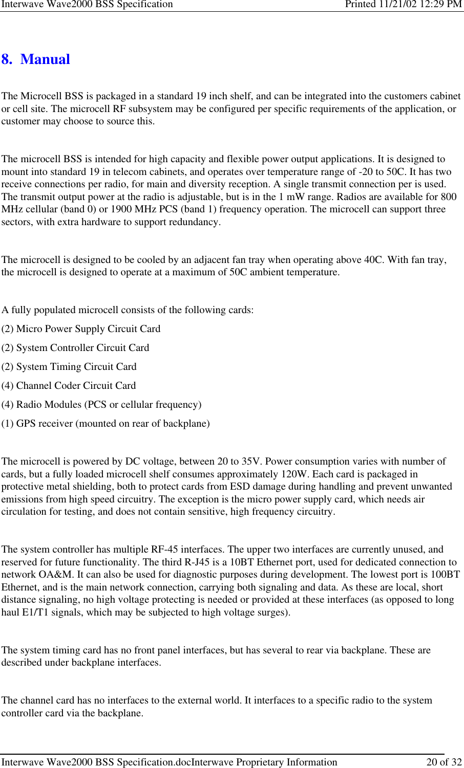
![Interwave Wave2000 BSS Specification Printed 11/21/02 12:29 PM Interwave Wave2000 BSS Specification.docInterwave Proprietary Information 23 of 32 8.1 5.3 System Configuration In the PC terminal, open two Hyper-terminals for COM 1 and COM 2 to monitor the SCON card and CHC card. Run a FTP server for uploading the application software into the SCON and CHC card. See details for setting up the FTP server in SCON or CHC testing documents. 1.1.1 5.3.1 Operating system configuration Firstly, configure the xvWorks operating system in both SCON and CHC cards in order to allow the PC terminal communicates with the SCON and CHC cards. Step1: Turn on the system, you should see the count down for booting up the system. "press any key to stop the auto-boot..." Before it finishes the count down, press “ESC” to stop the system to boot up, then you should see the vxWorks prompt as this [vxWorks Boot]: At the prompt, to see a list of available commands, type the help command (h or ?) followed by “ENTER”: [vxWorks Boot]: ? Step 2: To display the current or default boot parameters type “p” at the boot prompt, as follows: [vxWorks Boot]: p boot device : motfcc unit number : 0 processor number : 0 host name : host file name : D:\Tornado2\target\config\VssBsp\SconRevX\vxWorks.st inet on ethernet (e) : 192.168.1.68 inet on backplane (b): host inet (h) : 192.168.1.125 gateway inet (g) : 192.168.1.1 user (u) : target ftp password (pw) (blank = use rsh): target flags (f) : 0x0 target name (tn) : SconRev4 other (o) : motfcc Figure 8-11 vxWorks boot parameters in SCON [VxWorks Boot]: p boot device : cpm unit number : 1 processor number : 0](https://usermanual.wiki/ADC-Telecommunications/AGBB/User-Guide-301229-Page-4.png)
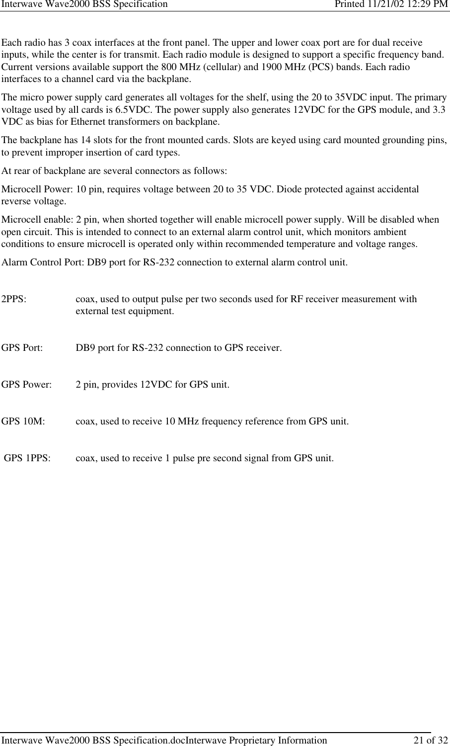
![Interwave Wave2000 BSS Specification Printed 11/21/02 12:29 PM Interwave Wave2000 BSS Specification.docInterwave Proprietary Information 24 of 32 host name : host file name : D:/tornado2/target/config/vssbsp/chc/vxWorks.st inet on ethernet (e) : 192.168.1.34 host inet (h) : 192.168.1.125 gateway inet (g) : 192.168.1.1 user (u) : target ftp password (pw) : target flags (f) : 0x0 target name (tn) : Chc66Mhz other (o) : cpm Figure 8-12 vxWorks boot parameters in CHC Step 3: To change the boot parameters type “c” at the boot prompt, as follows: [vxWorks Boot]: c boot device : tffs=0,00 _ If a particular field has the correct value already, press “ENTER”. To clear a field, enter a period(.), then press “ENTER”. If you want to quit before completing all the parameters, type CTRL+D. Or simply press “ENTER” all the way to the end of the table. Basically, for a new system, the following parameters need to be changed: • “file name” (the directory and path of the application image in the PC) • “inet on ethernet” (scon/chc ip address) • “host inet” (host computer ip address) • “gateway inet” (local network gateway) Other parameters should be kept the same. In some case, the user and ftp password have to be set also. Step 4: After the change, boot the system using the current boot parameters by typing “@” at the boot prompt or simple reboot the system. [vxWork Boot]: @ Remarks: In case of failing in booting up the vxWorks, check the Host IP address and the location of the application image file in the PC terminal. Also, the cable connection may also cause the problem. 1.1.2 5.3.2 Application system configuration Secondly, configure the application system parameters in SCON. After the vxWorks operating system booting up, there should be an arrow prompt “->” on the SCON console. At the prompt, type “showConfig” to the following manual: ->showConfig System Configuration Menu 1 - BSC Parameters. 2 - BTS Parameters.](https://usermanual.wiki/ADC-Telecommunications/AGBB/User-Guide-301229-Page-5.png)
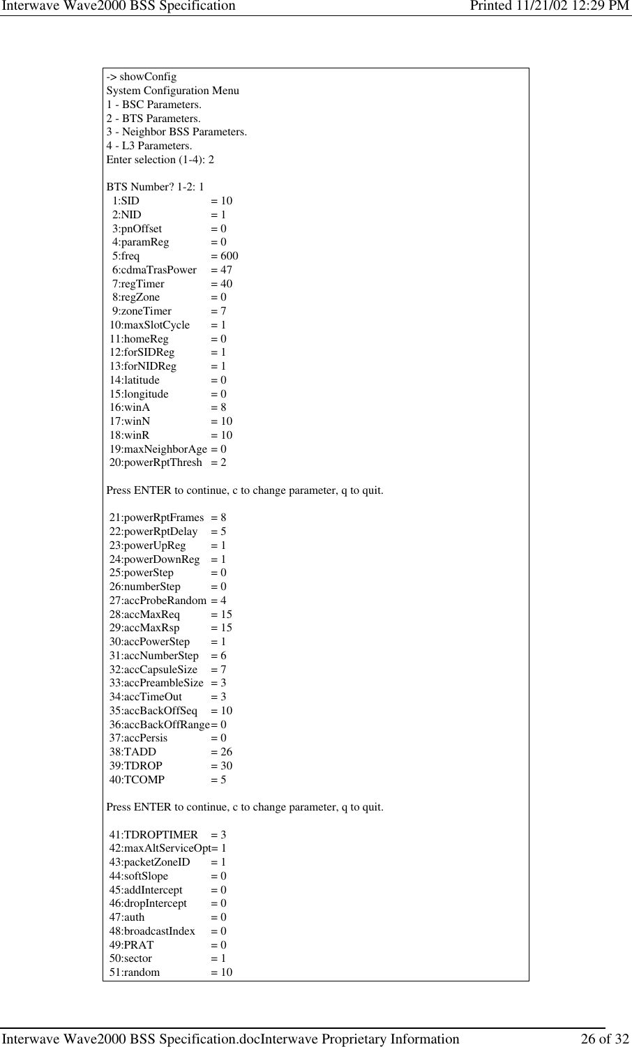
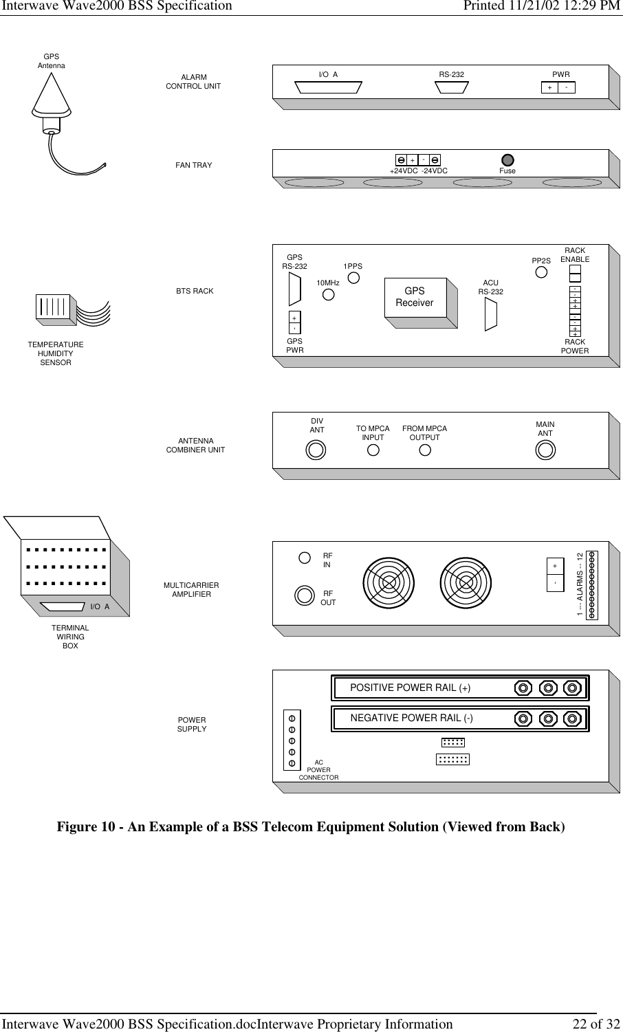
![Interwave Wave2000 BSS Specification Printed 11/21/02 12:29 PM Interwave Wave2000 BSS Specification.docInterwave Proprietary Information 27 of 32 52:rfSubSystemGain = 24 53:pcsMode = 1 Press ENTER to quit, c to change parameter. value = 0 = 0x0 -> Figure 8-15 BTS paramaters manual Change the following parameters according to the system setting: 01. SID System ID 02. NID Network ID 05. freq Channel frequency used 06. cdmaTrasPower Pilot transmit power. (from 26dBm to 36dBm) 52. pcsMode 1 = PCS, 0 = Cellular The rest of the parameters are not necessary to change at this moment, default values is good enough for the system. After finishing the system parameter setup, the application software can be executed by entering “interwaveSconEntry” at the SCON console prompt and “interwaveChcEntry” at the CHC console prompt. Make sure that the SCON application is run up completely first, and then CHC application. If not, the CHC will be rebooted automatically. After, the mobile phone should be locked to the BSS and ready for the testing section. For details description about the system configuration, see the reference [6].](https://usermanual.wiki/ADC-Telecommunications/AGBB/User-Guide-301229-Page-8.png)