ADC Telecommunications AGBB CDMA2000 Wireless Basestation User Manual Specification
ADC Telecommunications Inc. CDMA2000 Wireless Basestation Specification
User Manual

Interwave Wave2000 BSS Specification Printed 11/21/02 12:29 PM
Interwave Wave2000 BSS Specification.docInterwave Proprietary Information 20 of 32
8. Manual
The Microcell BSS is packaged in a standard 19 inch shelf, and can be integrated into the customers cabinet
or cell site. The microcell RF subsystem may be configured per specific requirements of the application, or
customer may choose to source this.
The microcell BSS is intended for high capacity and flexible power output applications. It is designed to
mount into standard 19 in telecom cabinets, and operates over temperature range of -20 to 50C. It has two
receive connections per radio, for main and diversity reception. A single transmit connection per is used.
The transmit output power at the radio is adjustable, but is in the 1 mW range. Radios are available for 800
MHz cellular (band 0) or 1900 MHz PCS (band 1) frequency operation. The microcell can support three
sectors, with extra hardware to support redundancy.
The microcell is designed to be cooled by an adjacent fan tray when operating above 40C. With fan tray,
the microcell is designed to operate at a maximum of 50C ambient temperature.
A fully populated microcell consists of the following cards:
(2) Micro Power Supply Circuit Card
(2) System Controller Circuit Card
(2) System Timing Circuit Card
(4) Channel Coder Circuit Card
(4) Radio Modules (PCS or cellular frequency)
(1) GPS receiver (mounted on rear of backplane)
The microcell is powered by DC voltage, between 20 to 35V. Power consumption varies with number of
cards, but a fully loaded microcell shelf consumes approximately 120W. Each card is packaged in
protective metal shielding, both to protect cards from ESD damage during handling and prevent unwanted
emissions from high speed circuitry. The exception is the micro power supply card, which needs air
circulation for testing, and does not contain sensitive, high frequency circuitry.
The system controller has multiple RF-45 interfaces. The upper two interfaces are currently unused, and
reserved for future functionality. The third R-J45 is a 10BT Ethernet port, used for dedicated connection to
network OA&M. It can also be used for diagnostic purposes during development. The lowest port is 100BT
Ethernet, and is the main network connection, carrying both signaling and data. As these are local, short
distance signaling, no high voltage protecting is needed or provided at these interfaces (as opposed to long
haul E1/T1 signals, which may be subjected to high voltage surges).
The system timing card has no front panel interfaces, but has several to rear via backplane. These are
described under backplane interfaces.
The channel card has no interfaces to the external world. It interfaces to a specific radio to the system
controller card via the backplane.

Interwave Wave2000 BSS Specification Printed 11/21/02 12:29 PM
Interwave Wave2000 BSS Specification.docInterwave Proprietary Information 21 of 32
Each radio has 3 coax interfaces at the front panel. The upper and lower coax port are for dual receive
inputs, while the center is for transmit. Each radio module is designed to support a specific frequency band.
Current versions available support the 800 MHz (cellular) and 1900 MHz (PCS) bands. Each radio
interfaces to a channel card via the backplane.
The micro power supply card generates all voltages for the shelf, using the 20 to 35VDC input. The primary
voltage used by all cards is 6.5VDC. The power supply also generates 12VDC for the GPS module, and 3.3
VDC as bias for Ethernet transformers on backplane.
The backplane has 14 slots for the front mounted cards. Slots are keyed using card mounted grounding pins,
to prevent improper insertion of card types.
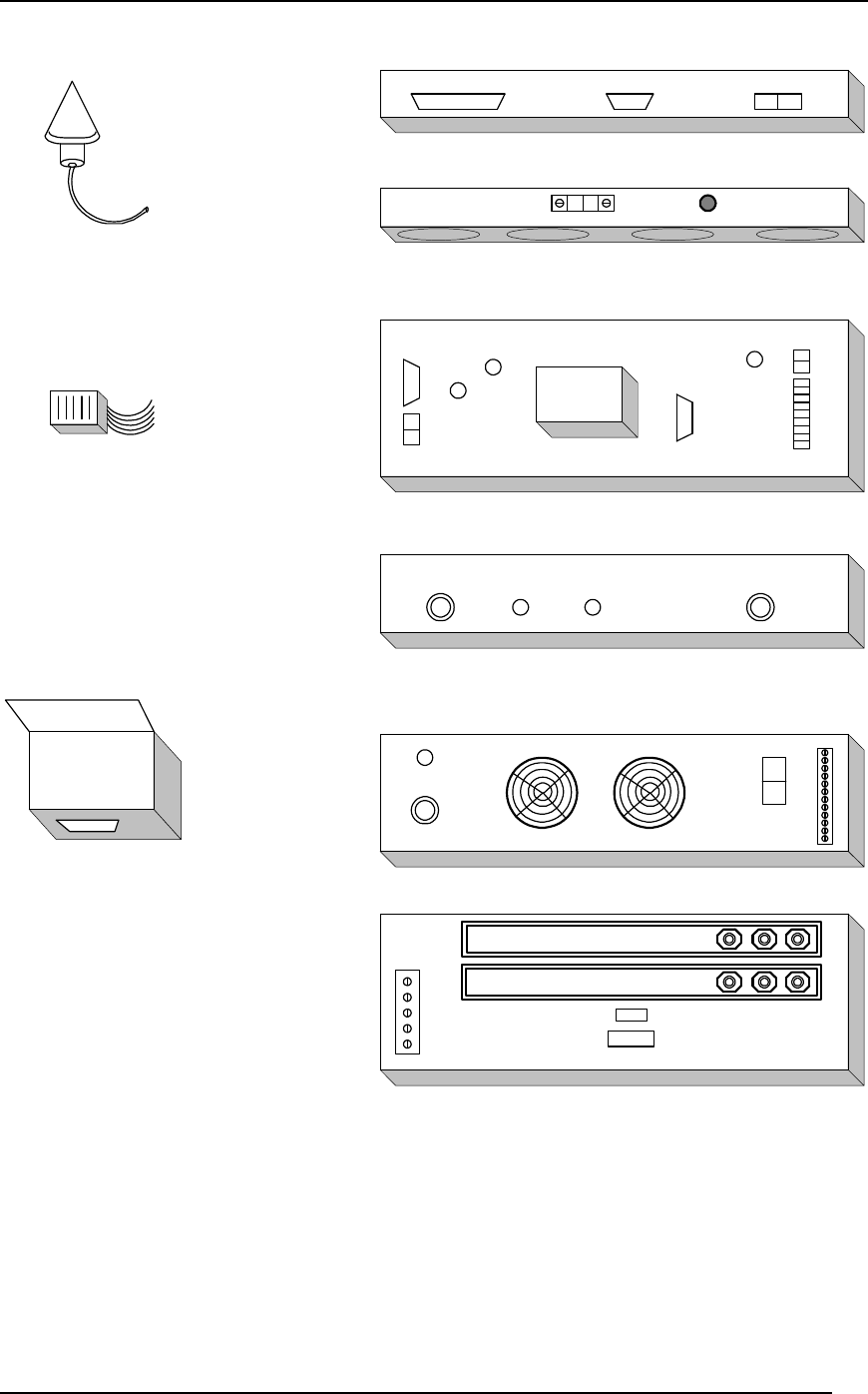
At rear of backplane are several connectors as follows:
Microcell Power: 10 pin, requires voltage between 20 to 35 VDC. Diode protected against accidental
reverse voltage.
Microcell enable: 2 pin, when shorted together will enable microcell power supply. Will be disabled when
open circuit. This is intended to connect to an external alarm control unit, which monitors ambient
conditions to ensure microcell is operated only within recommended temperature and voltage ranges.
Alarm Control Port: DB9 port for RS-232 connection to external alarm control unit.
2PPS: coax, used to output pulse per two seconds used for RF receiver measurement with
external test equipment.
GPS Port: DB9 port for RS-232 connection to GPS receiver.
GPS Power: 2 pin, provides 12VDC for GPS unit.
GPS 10M: coax, used to receive 10 MHz frequency reference from GPS unit.
GPS 1PPS: coax, used to receive 1 pulse pre second signal from GPS unit.
Interwave Wave2000 BSS Specification Printed 11/21/02 12:29 PM
Interwave Wave2000 BSS Specification.docInterwave Proprietary Information 22 of 32
ALARM
CONTROL UNIT
+-
GPS
RS-232
GPS
PWR
10MHz
1PPS
GPS
Receiver
ACU
RS-232
PP2S
RACK
ENABLE
RACK
POWER
RS-232 PWR
+-
+24VDC -24VDC
FAN TRAY
BTS RACK
ANTENNA
COMBINER UNIT
MULTICARRIER
AMPLIFIER
POWER
SUPPLY
TEMPERATURE
HUMIDITY
SENSOR
TO MPCA
INPUT FROM MPCA
OUTPUT
MAIN
ANT
RF
IN
RF
OUT
DIV
ANT
+-
1 --- ALARMS -- 12
+
+
+
+
-
-
-
-
POSITIVE POWER RAIL (+)
NEGATIVE POWER RAIL (-)
.....
.....
......
.......
.
AC
POWER
CONNECTOR
I/O A
..........
..........
..........
TERMINAL
WIRING
BOX
I/O A
GPS
Antenna
+-
Fuse
Figure 10 - An Example of a BSS Telecom Equipment Solution (Viewed from Back)

Interwave Wave2000 BSS Specification Printed 11/21/02 12:29 PM
Interwave Wave2000 BSS Specification.docInterwave Proprietary Information 23 of 32
8.1 5.3 System Configuration
In the PC terminal, open two Hyper-terminals for COM 1 and COM 2 to monitor the SCON card and CHC
card. Run a FTP server for uploading the application software into the SCON and CHC card. See details
for setting up the FTP server in SCON or CHC testing documents.
1.1.1 5.3.1 Operating system configuration
Firstly, configure the xvWorks operating system in both SCON and CHC cards in order
to allow the PC terminal communicates with the SCON and CHC cards.
Step1:
Turn on the system, you should see the count down for booting up the system.
"press any key to stop the auto-boot..."
Before it finishes the count down, press “ESC” to stop the system to boot up, then you should see the
vxWorks prompt as this [vxWorks Boot]:
At the prompt, to see a list of available commands, type the help command (h or ?)
followed by “ENTER”:
[vxWorks Boot]: ?
Step 2:
To display the current or default boot parameters type “p” at the boot prompt, as follows:
[vxWorks Boot]: p
boot device : motfcc
unit number : 0
processor number : 0
host name : host
file name : D:\Tornado2\target\config\VssBsp\SconRevX\vxWorks.st
inet on ethernet (e) : 192.168.1.68
inet on backplane (b):
host inet (h) : 192.168.1.125
gateway inet (g) : 192.168.1.1
user (u) : target
ftp password (pw) (blank = use rsh): target
flags (f) : 0x0
target name (tn) : SconRev4
other (o) : motfcc
Figure 8-11 vxWorks boot parameters in SCON
[VxWorks Boot]: p
boot device : cpm
unit number : 1
processor number : 0

Interwave Wave2000 BSS Specification Printed 11/21/02 12:29 PM
Interwave Wave2000 BSS Specification.docInterwave Proprietary Information 24 of 32
host name : host
file name : D:/tornado2/target/config/vssbsp/chc/vxWorks.st
inet on ethernet (e) : 192.168.1.34
host inet (h) : 192.168.1.125
gateway inet (g) : 192.168.1.1
user (u) : target
ftp password (pw) : target
flags (f) : 0x0
target name (tn) : Chc66Mhz
other (o) : cpm
Figure 8-12 vxWorks boot parameters in CHC
Step 3:
To change the boot parameters type “c” at the boot prompt, as follows:
[vxWorks Boot]: c
boot device : tffs=0,00 _
If a particular field has the correct value already, press “ENTER”. To clear a field, enter a period(.), then
press “ENTER”. If you want to quit before completing all the parameters, type CTRL+D. Or simply press
“ENTER” all the way to the end of the table.
Basically, for a new system, the following parameters need to be changed:
• “file name” (the directory and path of the application image in the PC)
• “inet on ethernet” (scon/chc ip address)
• “host inet” (host computer ip address)
• “gateway inet” (local network gateway)
Other parameters should be kept the same. In some case, the user and ftp password have to be set also.
Step 4:
After the change, boot the system using the current boot parameters by typing “@” at the boot prompt or
simple reboot the system.
[vxWork Boot]: @
Remarks:
In case of failing in booting up the vxWorks, check the Host IP address and the location of the application image file in the PC
terminal. Also, the cable connection may also cause the problem.
1.1.2 5.3.2 Application system configuration
Secondly, configure the application system parameters in SCON. After the vxWorks operating system
booting up, there should be an arrow prompt “->” on the SCON console. At the prompt, type
“showConfig” to the following manual:
->showConfig
System Configuration Menu
1 - BSC Parameters.
2 - BTS Parameters.

Interwave Wave2000 BSS Specification Printed 11/21/02 12:29 PM
Interwave Wave2000 BSS Specification.docInterwave Proprietary Information 25 of 32
3 - Neighbor BSS Parameters.
4 - L3 Parameters.
Enter selection (1-4):
Figure 8-13 Configuration Manual
Choose the 1st option, BSC Parameters, and the following manual will show on the screen:
showConfig
System Configuration Menu
1 - BSC Parameters.
2 - BTS Parameters.
3 - Neighbor BSS Parameters.
4 - L3 Parameters.
Enter selection (1-4): 1
1:alarmDelay = 4
2:cellID = 2
3:cellMSCID = 0
4:disableCheck = 1
5:keepAliveTx = 25
6:keepAliveRx = 30
7:localTimeOffset = 50
8:telsecPresent = 0
9:mscIp = 207.23.93.8
10:mscPort = 5000
11:maxTIARTimeOut= 1
12:numOfBts = 1
13:numNeighBSS = 0
14:pdsnip = 192.168.1.123
15:sysName = InterWAVEScon
16:sysContact = InterWAVE Communications
17:sysLocation = Walnut Creek, CA
18:snmpMgrIpAddr = 192.168.1.80
19:snmpTrapPort = 162
20:snmpRequestPort = 161
Press ENTER to continue, c to change parameter, q to quit.
21:thisBscID = 1
22:timingCardDelay = 0
23:ssn = 252
24:mscPresent = 0
Press ENTER to quit, c to change parameter.
value = 0 = 0x0
->
Figure 8-14 BSS parameters manual
Change the following parameters according to the system setting:
08. telsecPresent 0= Indoor Pico,1 = Micro Cell, 2 = Outdoor Pico
Cell.
12. numOfBts Number of CHC in the system, i.e. PICO Cell can
be 1 or 2.
Next, Choose the 2nd option, BTS Parameters, and choose the CHC card which need to be configured, for
example, if there’s two CHC card in the MICRO Cell, enter 1 to configure the primary CHC card, enter 2 to
configure the secondary card.

Interwave Wave2000 BSS Specification Printed 11/21/02 12:29 PM
Interwave Wave2000 BSS Specification.docInterwave Proprietary Information 26 of 32
-> showConfig
System Configuration Menu
1 - BSC Parameters.
2 - BTS Parameters.
3 - Neighbor BSS Parameters.
4 - L3 Parameters.
Enter selection (1-4): 2
BTS Number? 1-2: 1
1:SID = 10
2:NID = 1
3:pnOffset = 0
4:paramReg = 0
5:freq = 600
6:cdmaTrasPower = 47
7:regTimer = 40
8:regZone = 0
9:zoneTimer = 7
10:maxSlotCycle = 1
11:homeReg = 0
12:forSIDReg = 1
13:forNIDReg = 1
14:latitude = 0
15:longitude = 0
16:winA = 8
17:winN = 10
18:winR = 10
19:maxNeighborAge = 0
20:powerRptThresh = 2
Press ENTER to continue, c to change parameter, q to quit.
21:powerRptFrames = 8
22:powerRptDelay = 5
23:powerUpReg = 1
24:powerDownReg = 1
25:powerStep = 0
26:numberStep = 0
27:accProbeRandom = 4
28:accMaxReq = 15
29:accMaxRsp = 15
30:accPowerStep = 1
31:accNumberStep = 6
32:accCapsuleSize = 7
33:accPreambleSize = 3
34:accTimeOut = 3
35:accBackOffSeq = 10
36:accBackOffRange = 0
37:accPersis = 0
38:TADD = 26
39:TDROP = 30
40:TCOMP = 5
Press ENTER to continue, c to change parameter, q to quit.
41:TDROPTIMER = 3
42:maxAltServiceOpt= 1
43:packetZoneID = 1
44:softSlope = 0
45:addIntercept = 0
46:dropIntercept = 0
47:auth = 0
48:broadcastIndex = 0
49:PRAT = 0
50:sector = 1
51:random = 10

Interwave Wave2000 BSS Specification Printed 11/21/02 12:29 PM
Interwave Wave2000 BSS Specification.docInterwave Proprietary Information 27 of 32
52:rfSubSystemGain = 24
53:pcsMode = 1
Press ENTER to quit, c to change parameter.
value = 0 = 0x0
->
Figure 8-15 BTS paramaters manual
Change the following parameters according to the system setting:
01. SID System ID
02. NID Network ID
05. freq Channel frequency used
06. cdmaTrasPower Pilot transmit power. (from 26dBm to 36dBm)
52. pcsMode 1 = PCS, 0 = Cellular
The rest of the parameters are not necessary to change at this moment, default values is good enough for the
system.
After finishing the system parameter setup, the application software can be executed by entering
“interwaveSconEntry” at the SCON console prompt and “interwaveChcEntry” at the CHC console prompt.
Make sure that the SCON application is run up completely first, and then CHC application. If not, the
CHC will be rebooted automatically. After, the mobile phone should be locked to the BSS and ready for
the testing section. For details description about the system configuration, see the reference [6].