ADC Telecommunications AKAD19 GSM Base Station User Manual
ADC Telecommunications Inc. GSM Base Station
UserManual.wiki
>
ADC Telecommunications
>
AKAD19 User Manual
User Manual
Navigation menu
Upload a User Manual
Namespaces
Wiki Guide
HTML
PDF
Info
Views
User Manual
Discussion / Help
Navigation
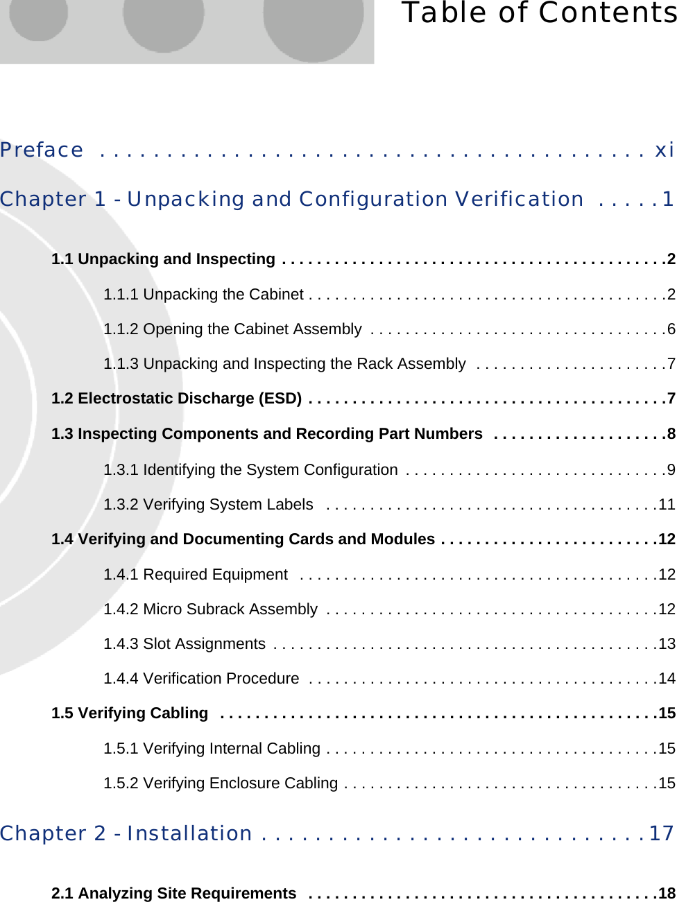

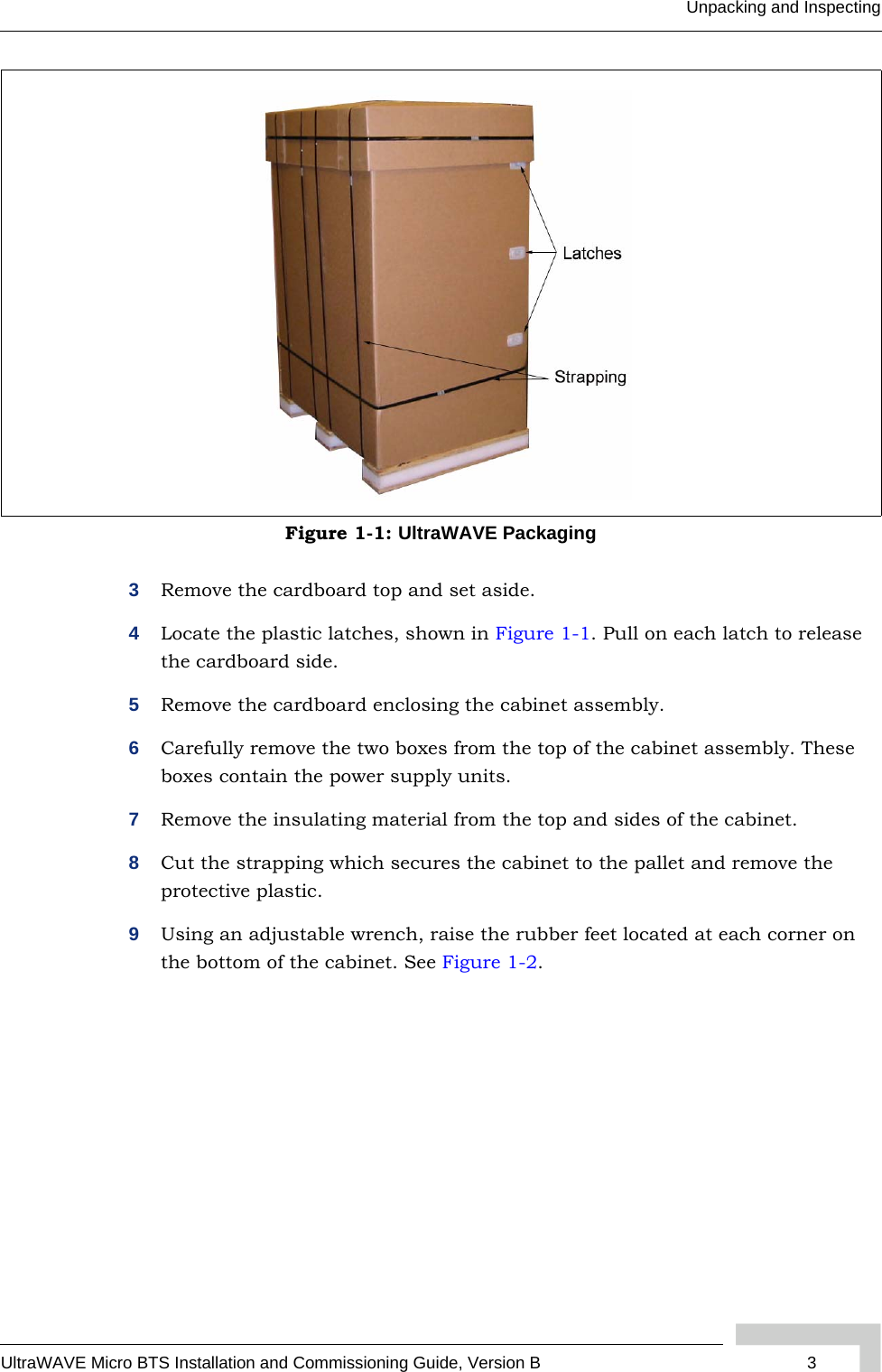
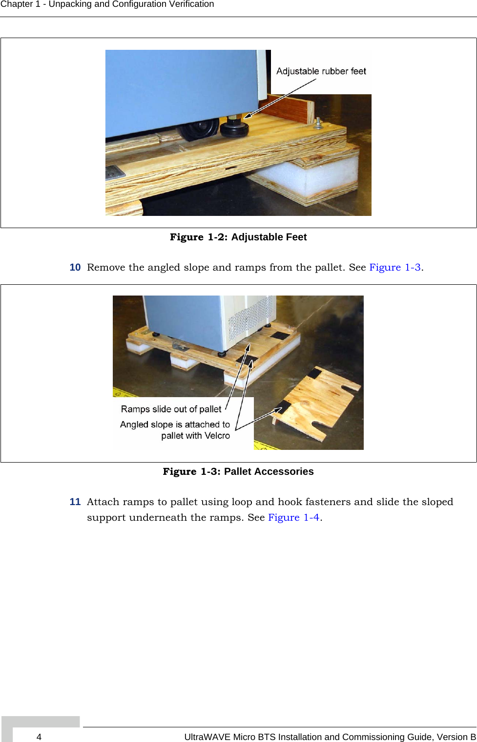
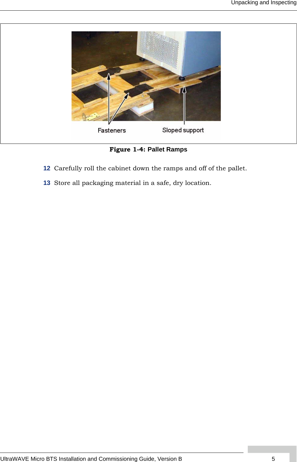
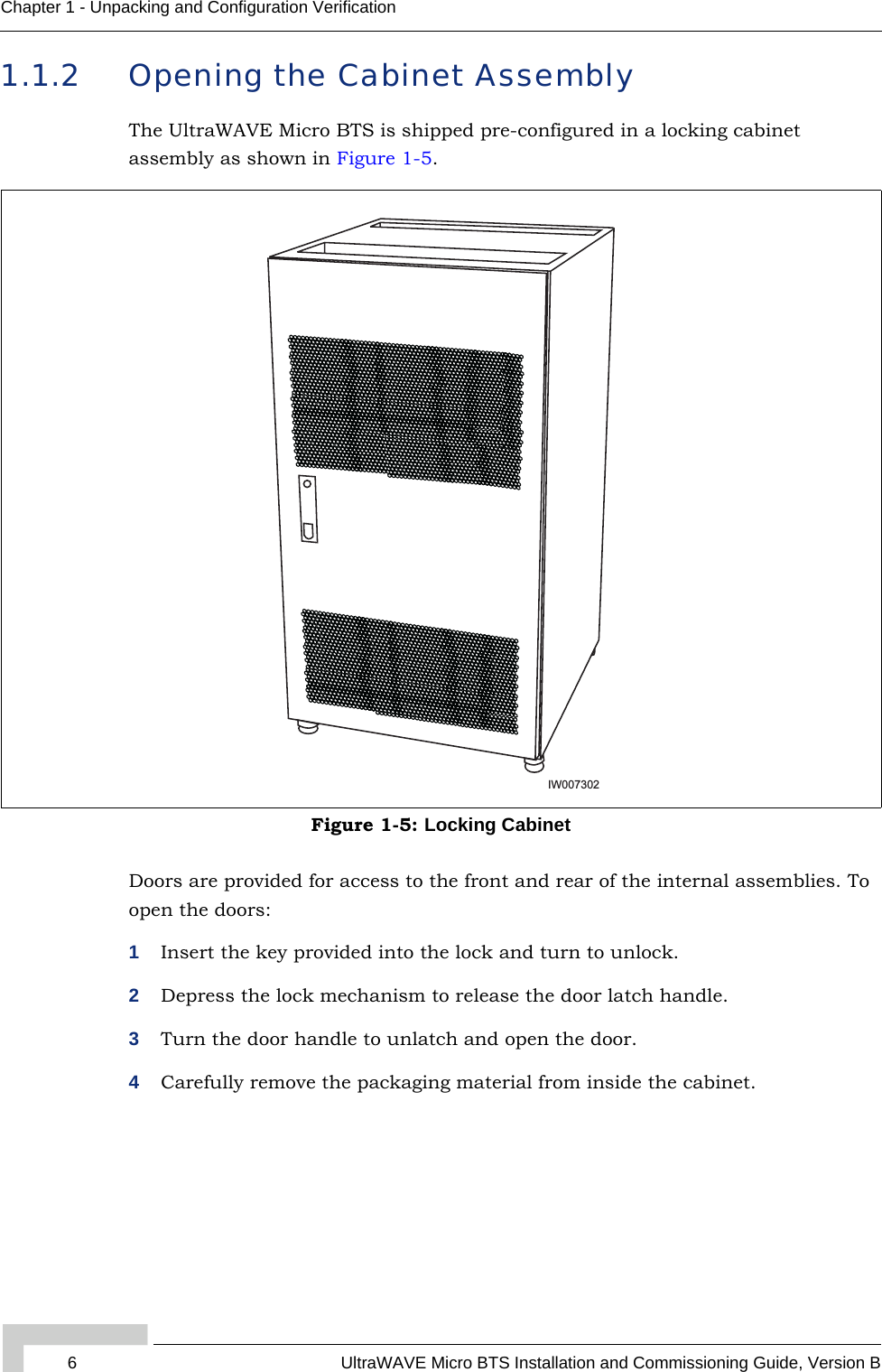
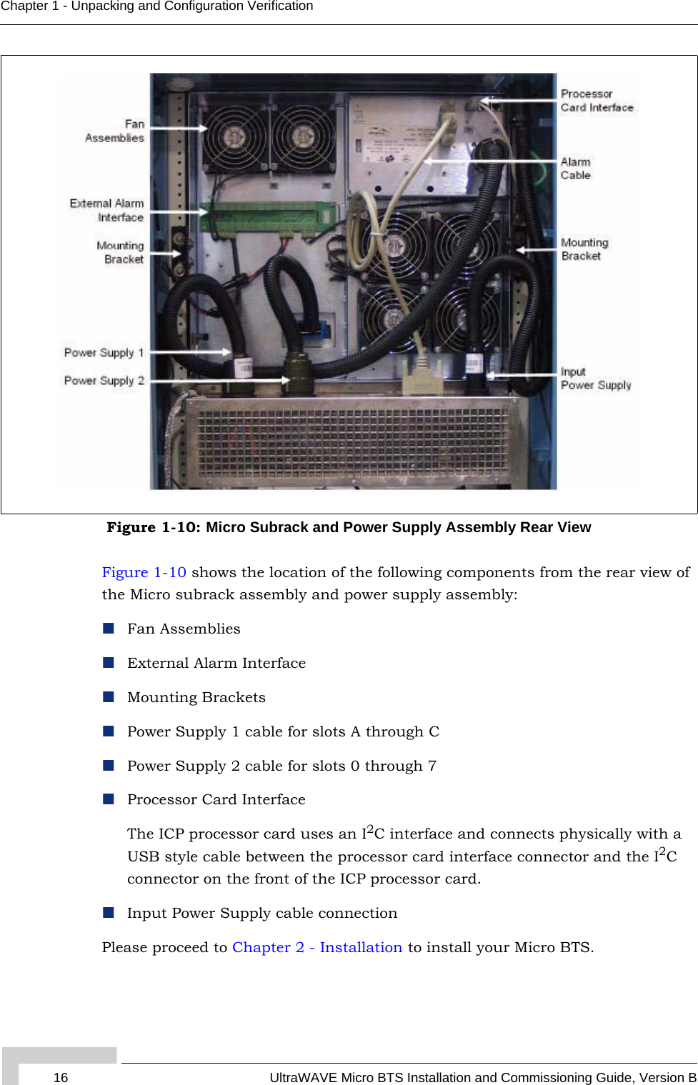
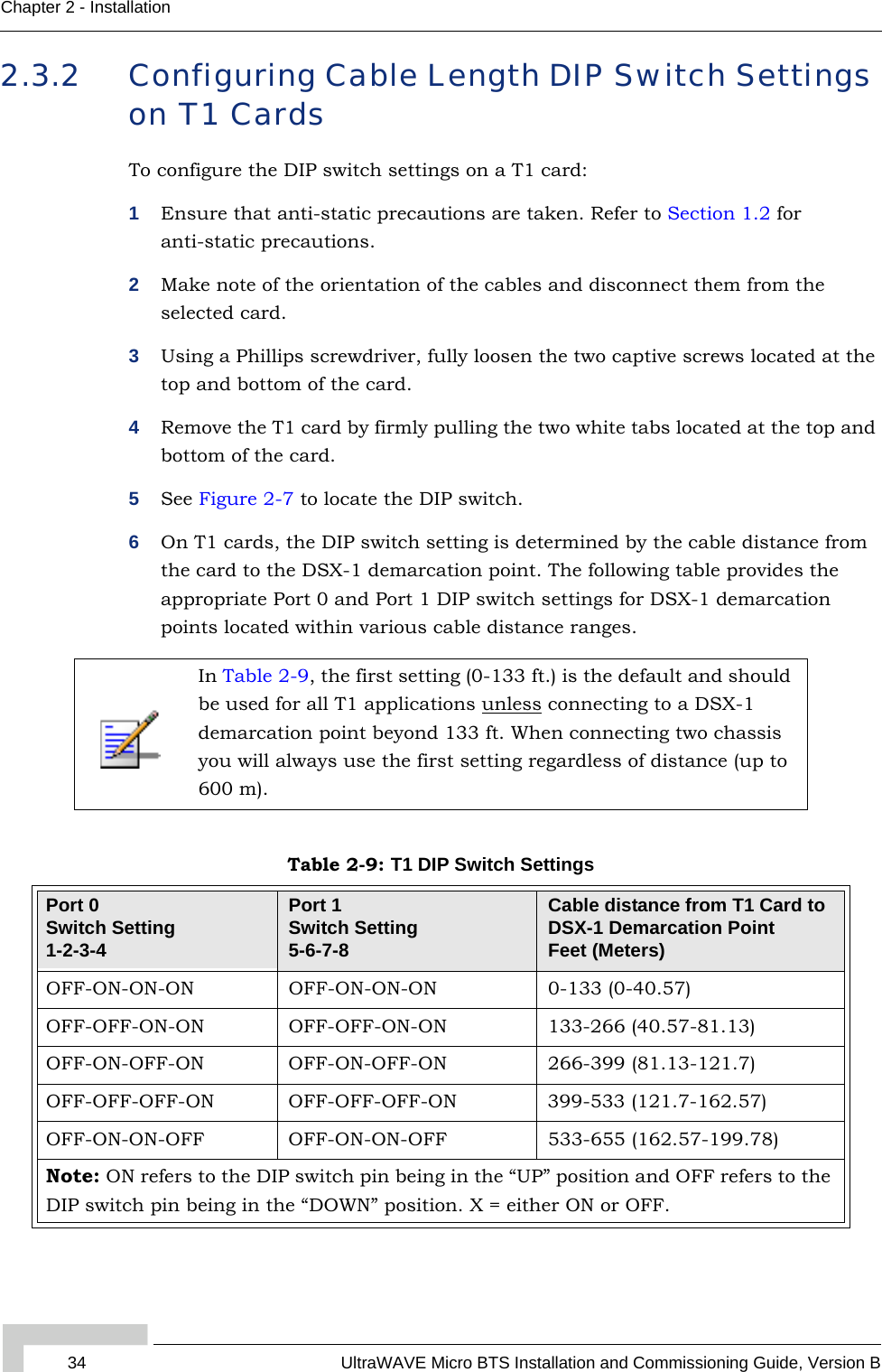
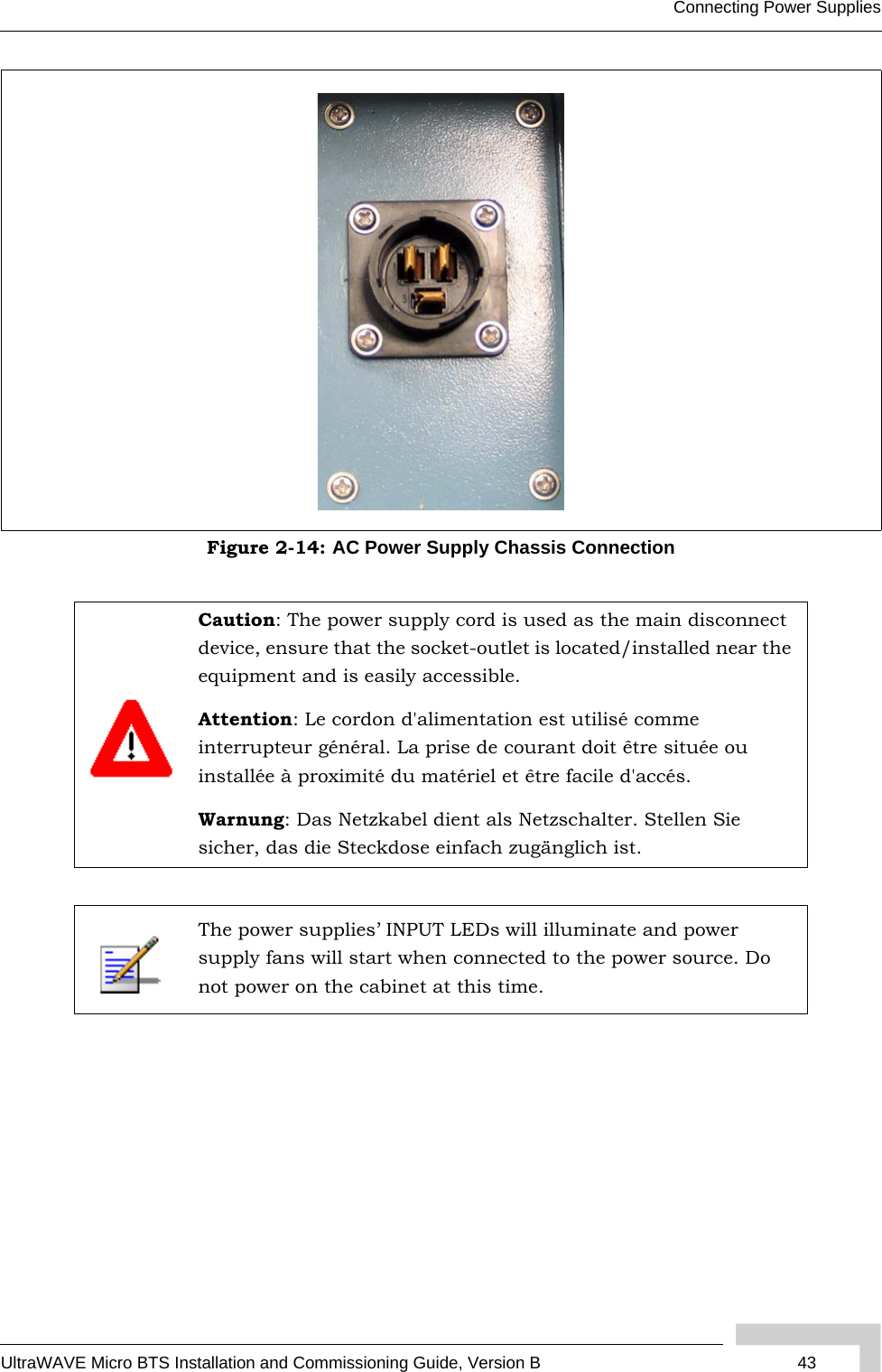
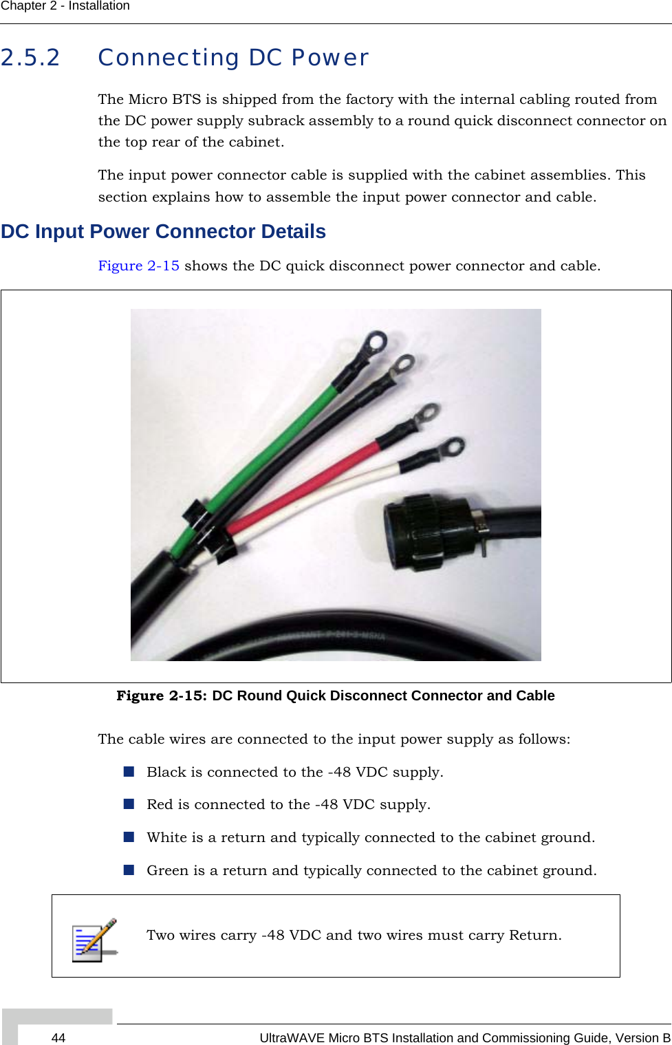
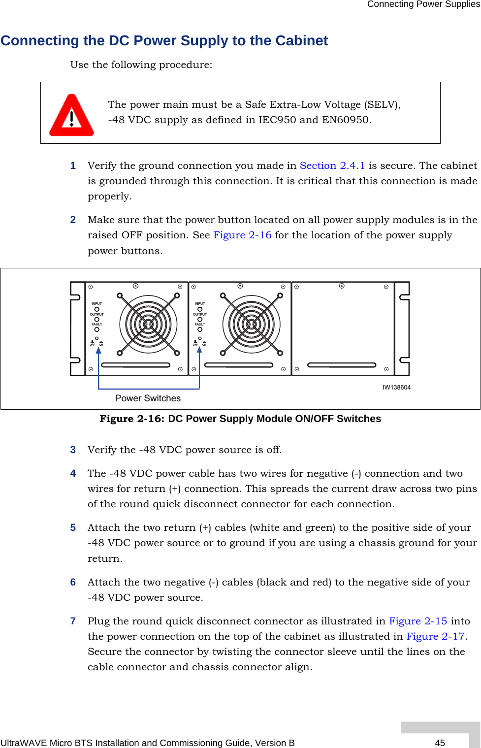
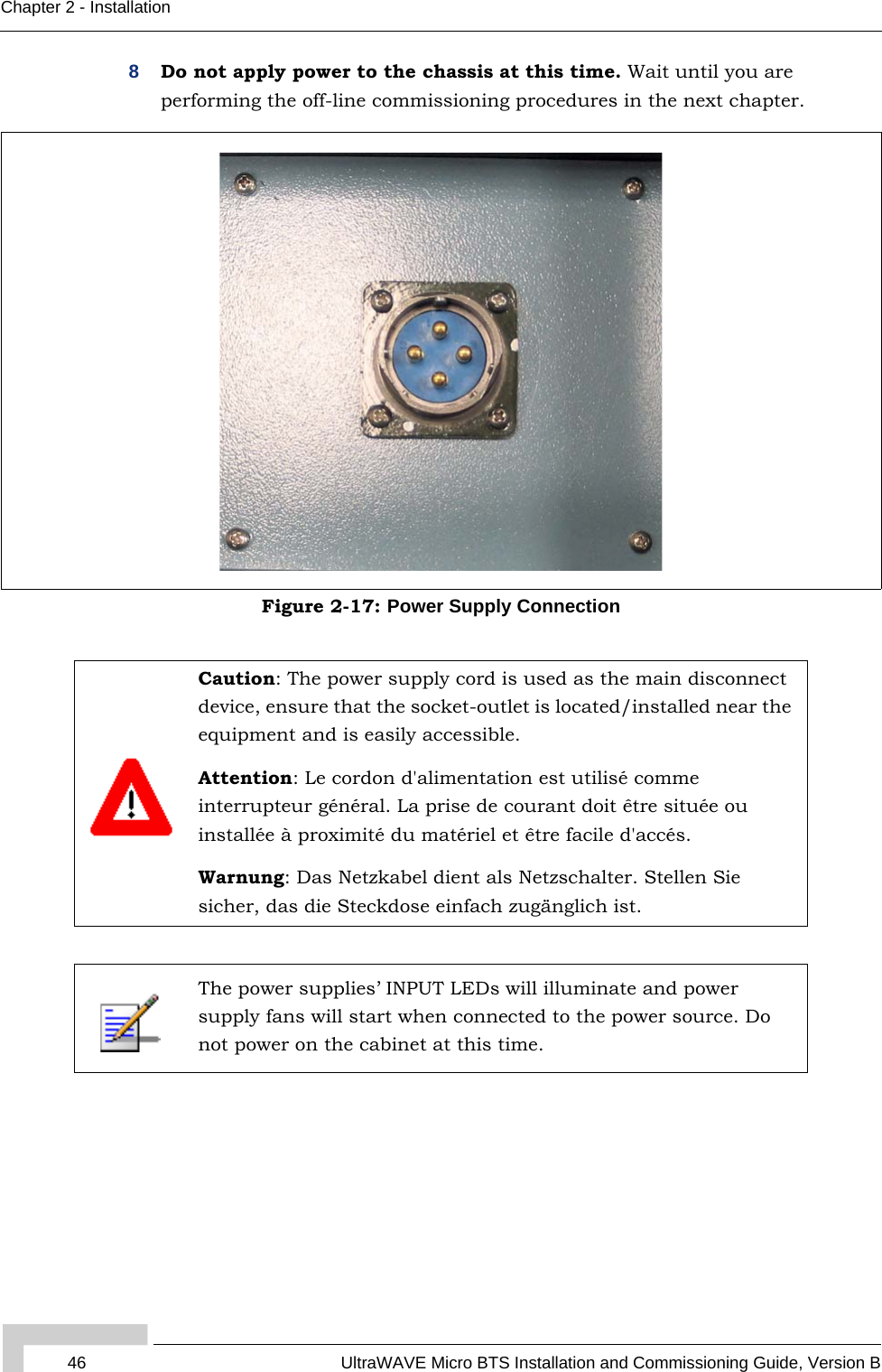
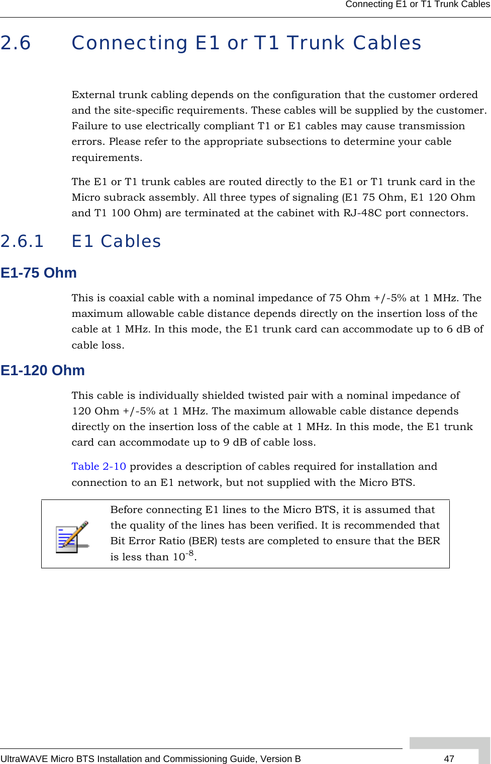
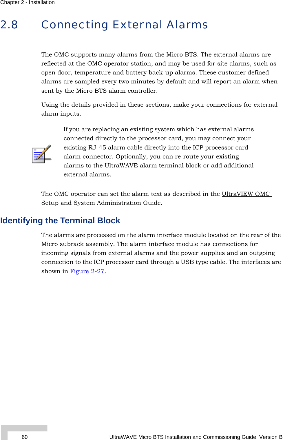
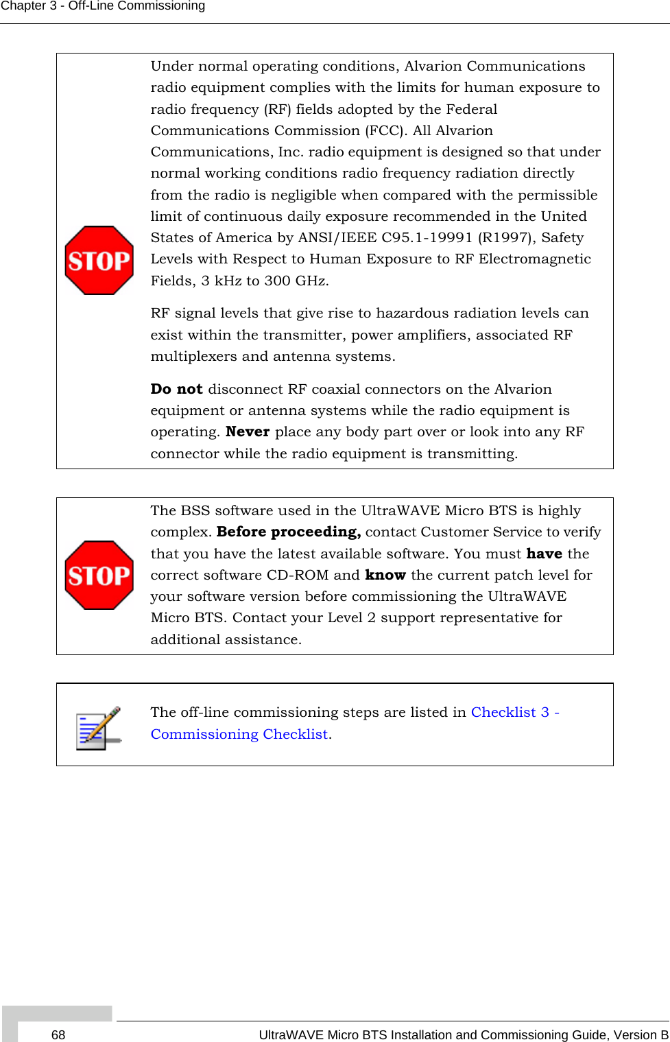
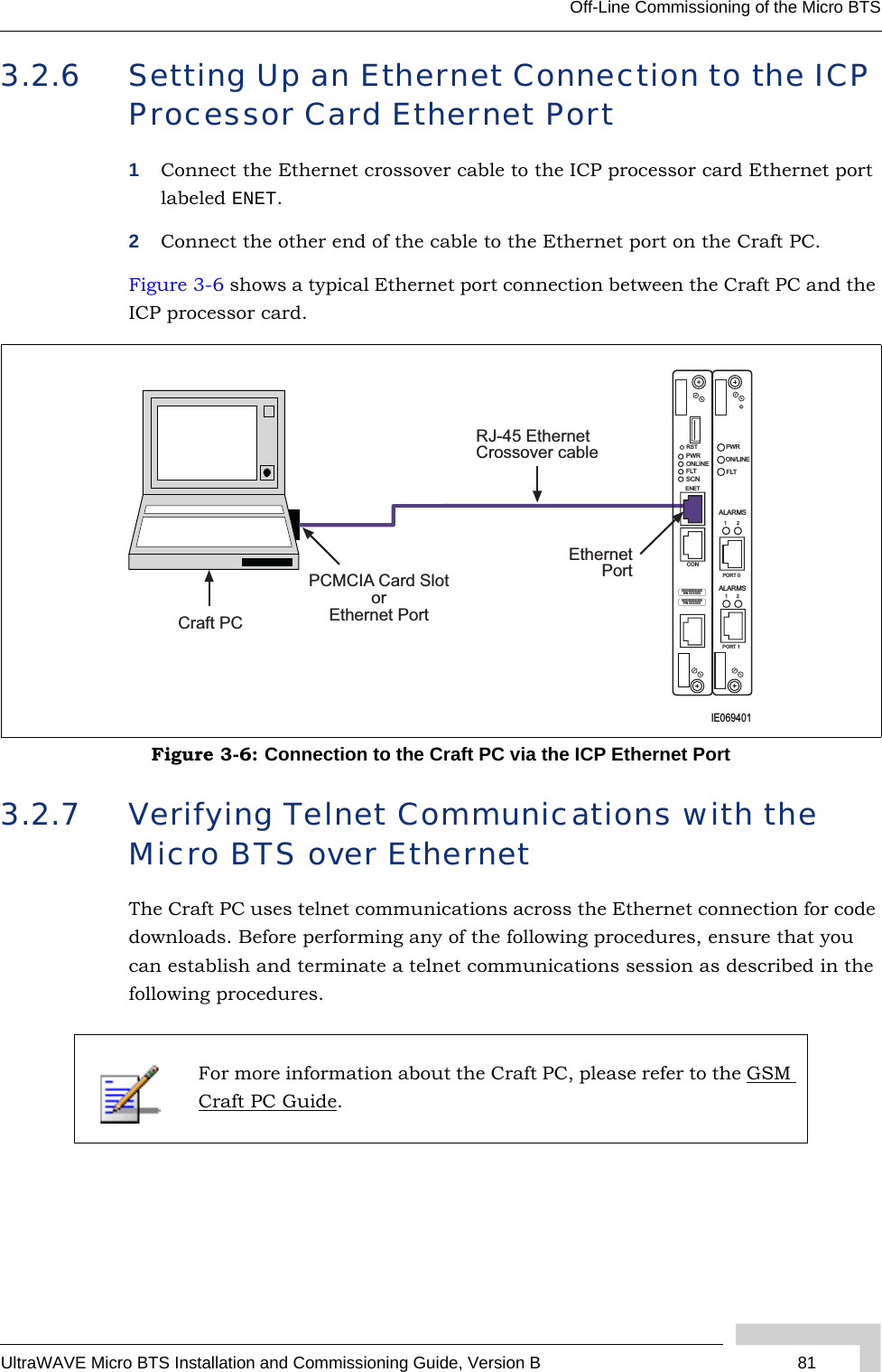
![xvi UltraWAVE Micro BTS Installation and Commissioning Guide, Version BPrefaceConventions Used in This ManualThe following type and style conventions are used in this manual:Conventions Used in This Manual Convention MeaningBody Text Used for regular body textBold Indicates a menu or button choiceCommand Indicates computer generated text and promptsUser Input Indicates user input<hostname> In command syntax, indicates user-specified command line parameters<variable> In body text, indicates user-specified command line parameters[BRACKETS] Indicates a key on the keyboard or instrumentProvides relevant additional informationProvides important warning information that may affect operation of or maybe a potential threat to the systemUsed to tell the reader to STOP what they are doing and to read important instructions that are vital to prevent equipment or software damage](https://usermanual.wiki/ADC-Telecommunications/AKAD19/User-Guide-723035-Page-16.png)
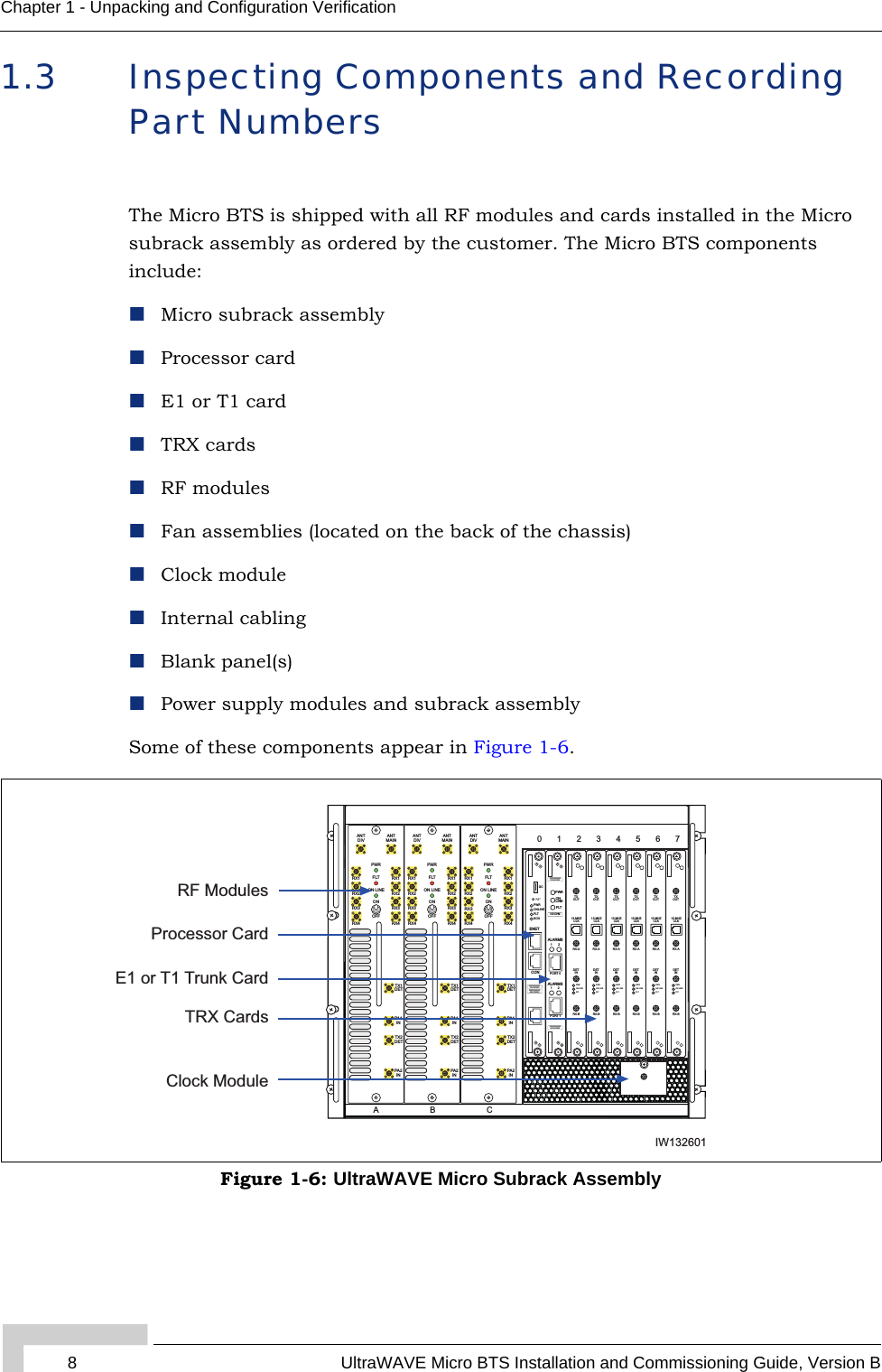
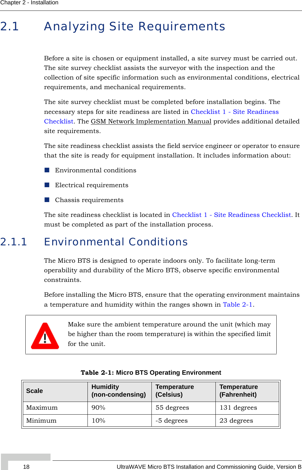
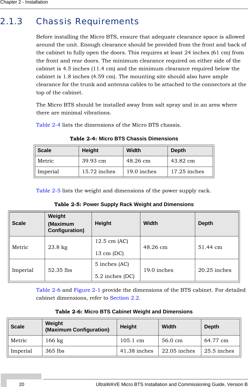
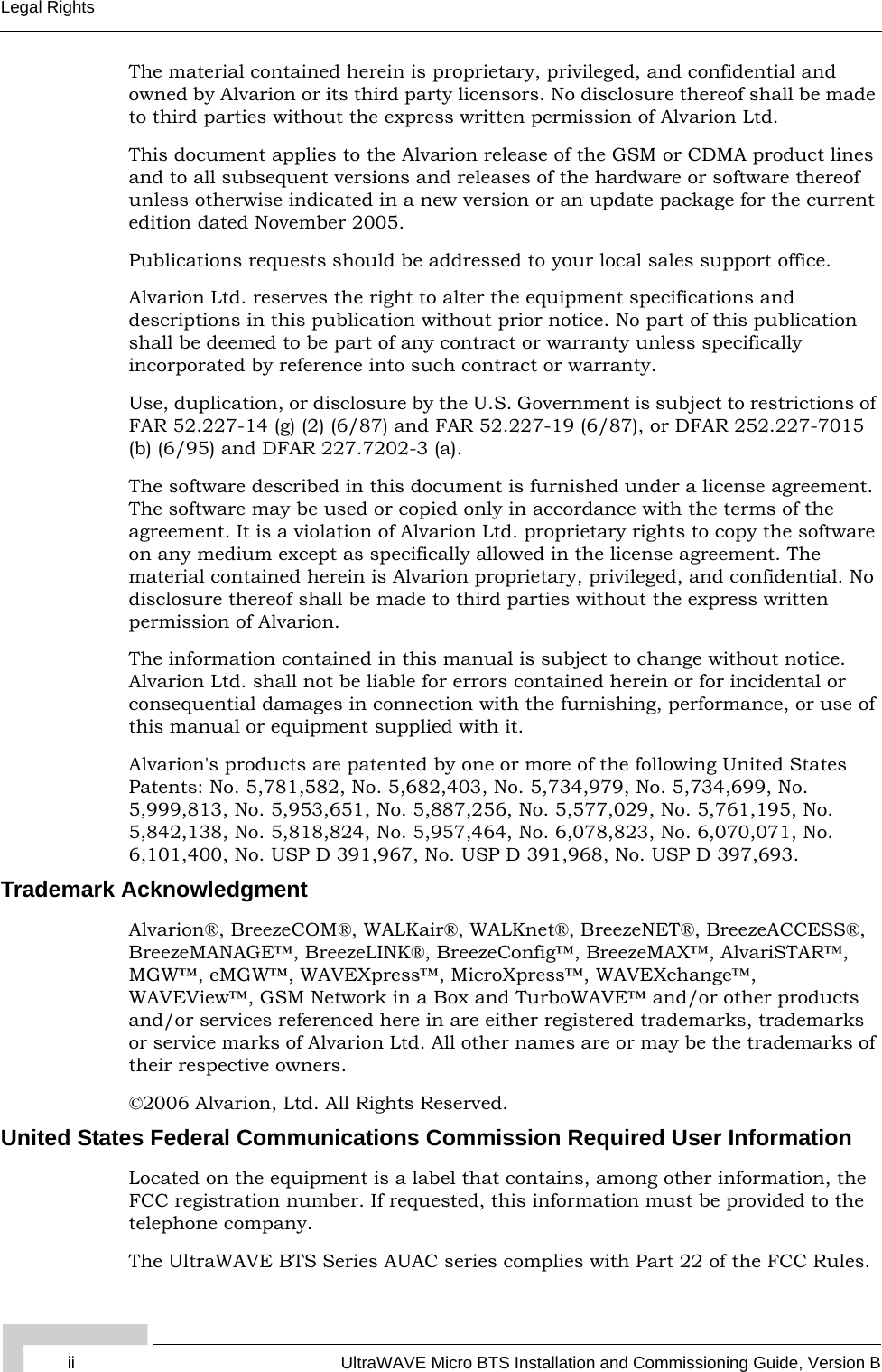
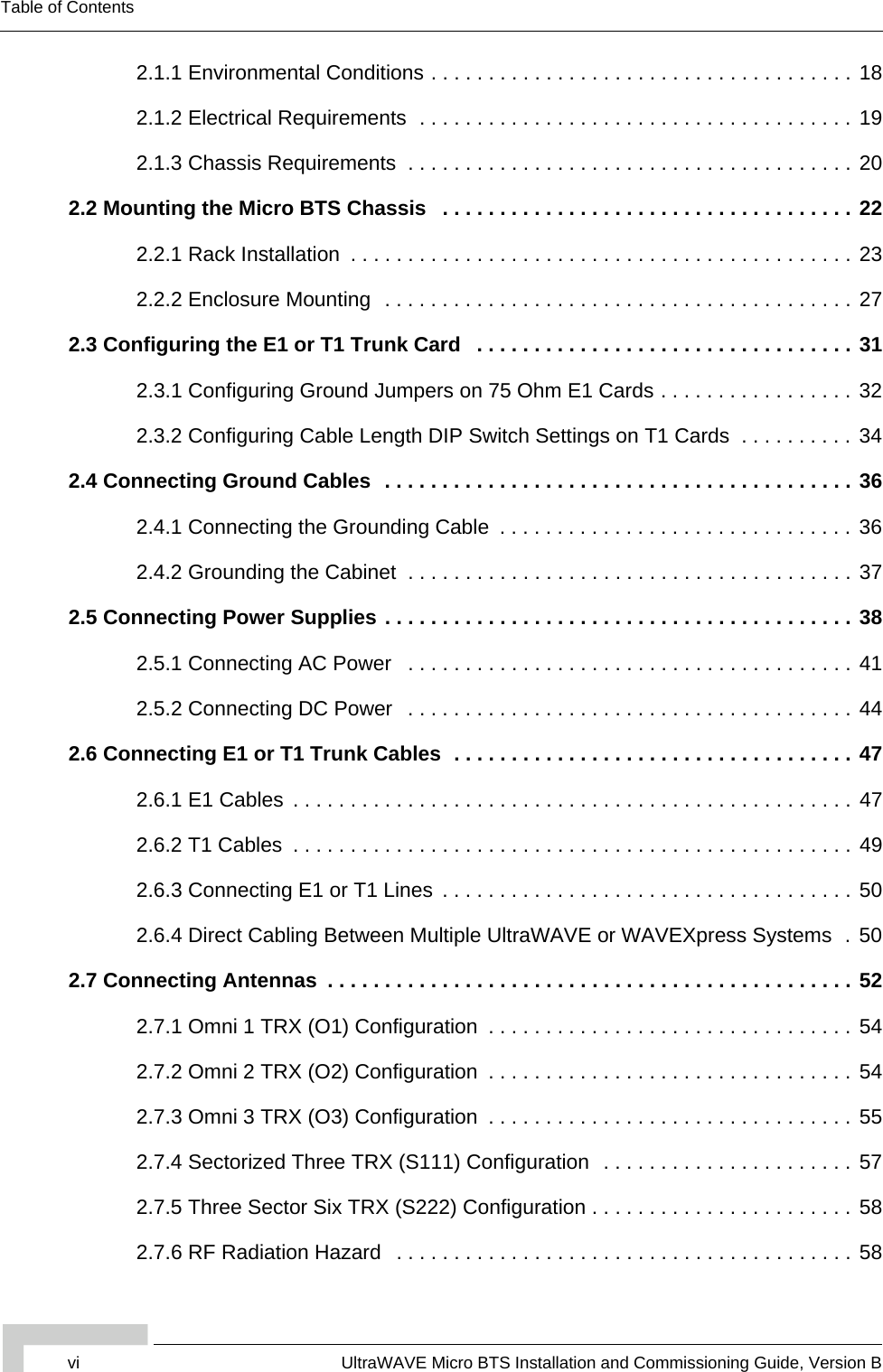
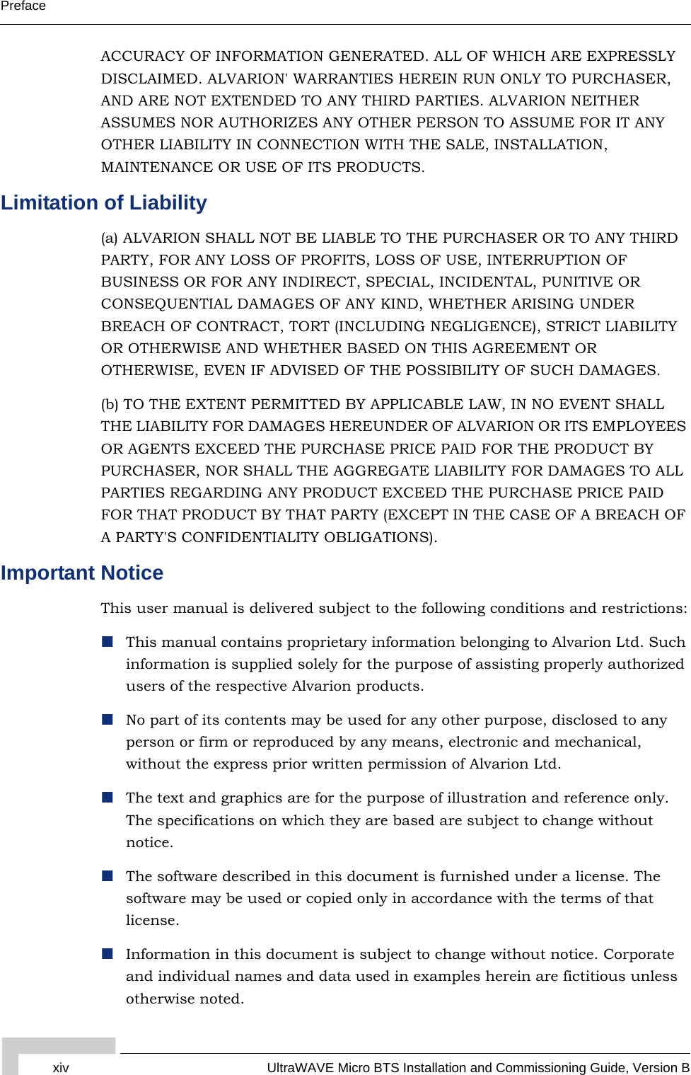
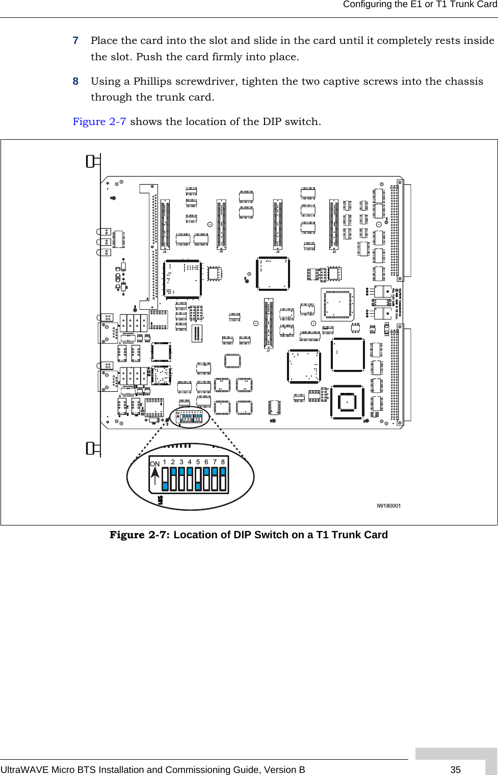
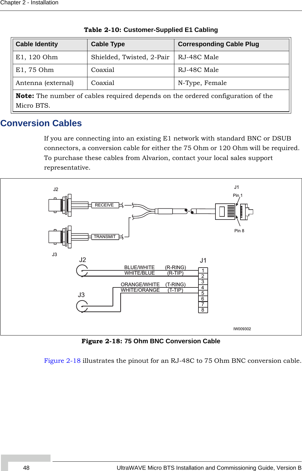
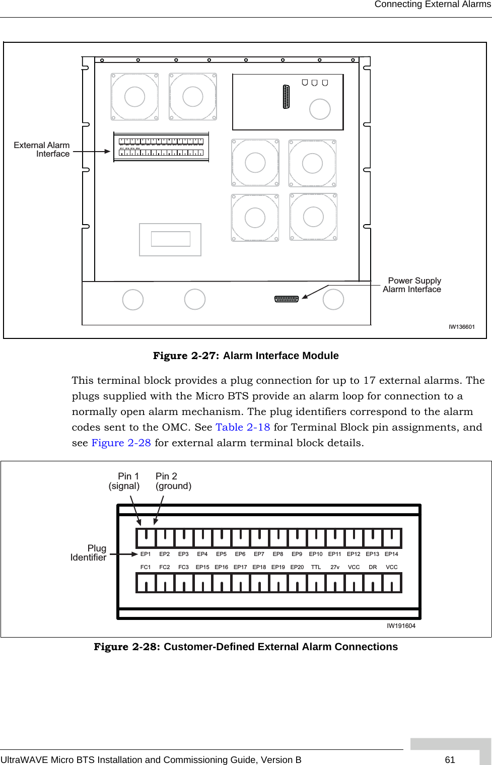
![UltraWAVE Micro BTS Installation and Commissioning Guide, Version B 21Analyzing Site RequirementsWhen fully loaded, two people are required to lift the chassis. (The two man lift requirement applies to loads of over 80 kg.)Figure 2-1: Cabinet Footing DimensionsThe steps for site readiness are listed in Checklist 1 - Site Readiness Checklist.WHEEL_SVWHEEL_SVWHEEL_FVWHEEL_FV WHEEL_FVDOOR_DOOR_FVFVCAB_FCAB_FVVRUBFERUBFEETETRUBFERUBFEETETCAB_SCAB_SVVDOOR_DOOR_SVSVDOOR_DOOR_SVSVRUBFERUBFEETETRUBFERUBFEETET20.925 in. [53.15 cm]M12-1.75(each corner)1.808 in[4.59 cm]19.925 in. [50.61 cm]41.375 in. [105.09 cm]IW008301M10 Tap Holes(each corner)](https://usermanual.wiki/ADC-Telecommunications/AKAD19/User-Guide-723035-Page-37.png)
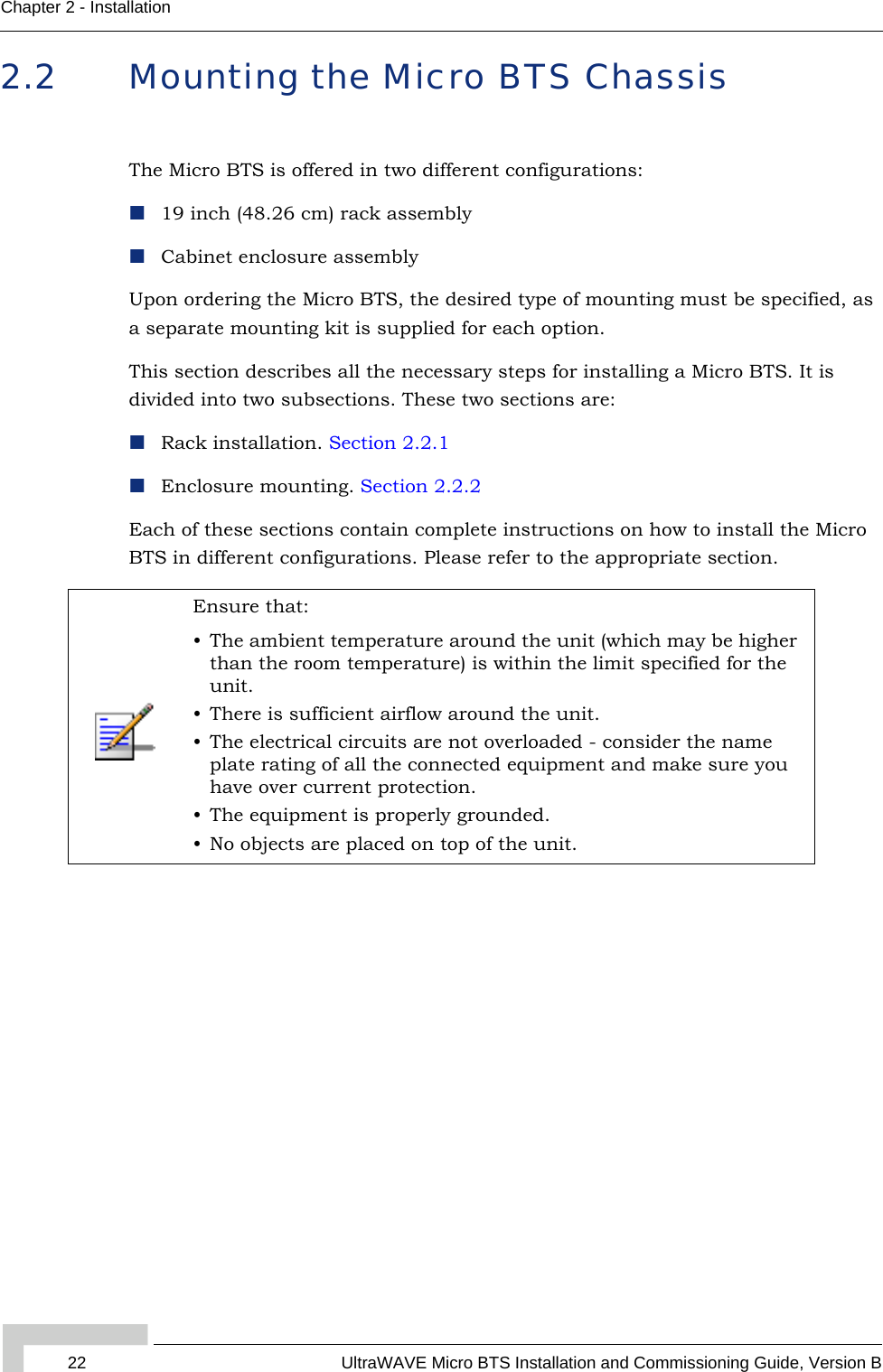
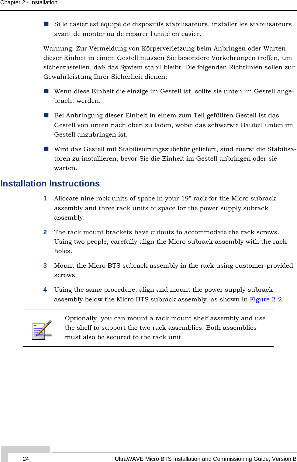
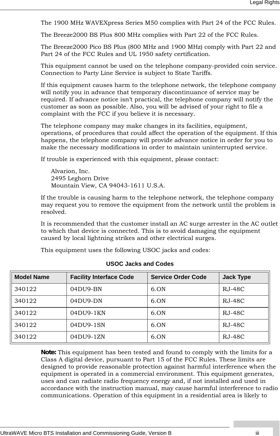
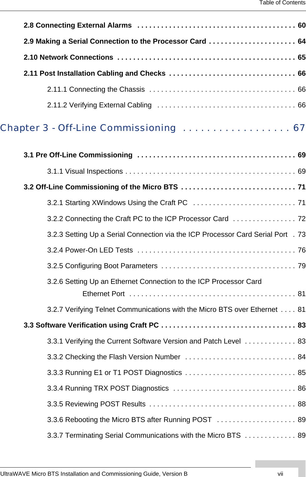
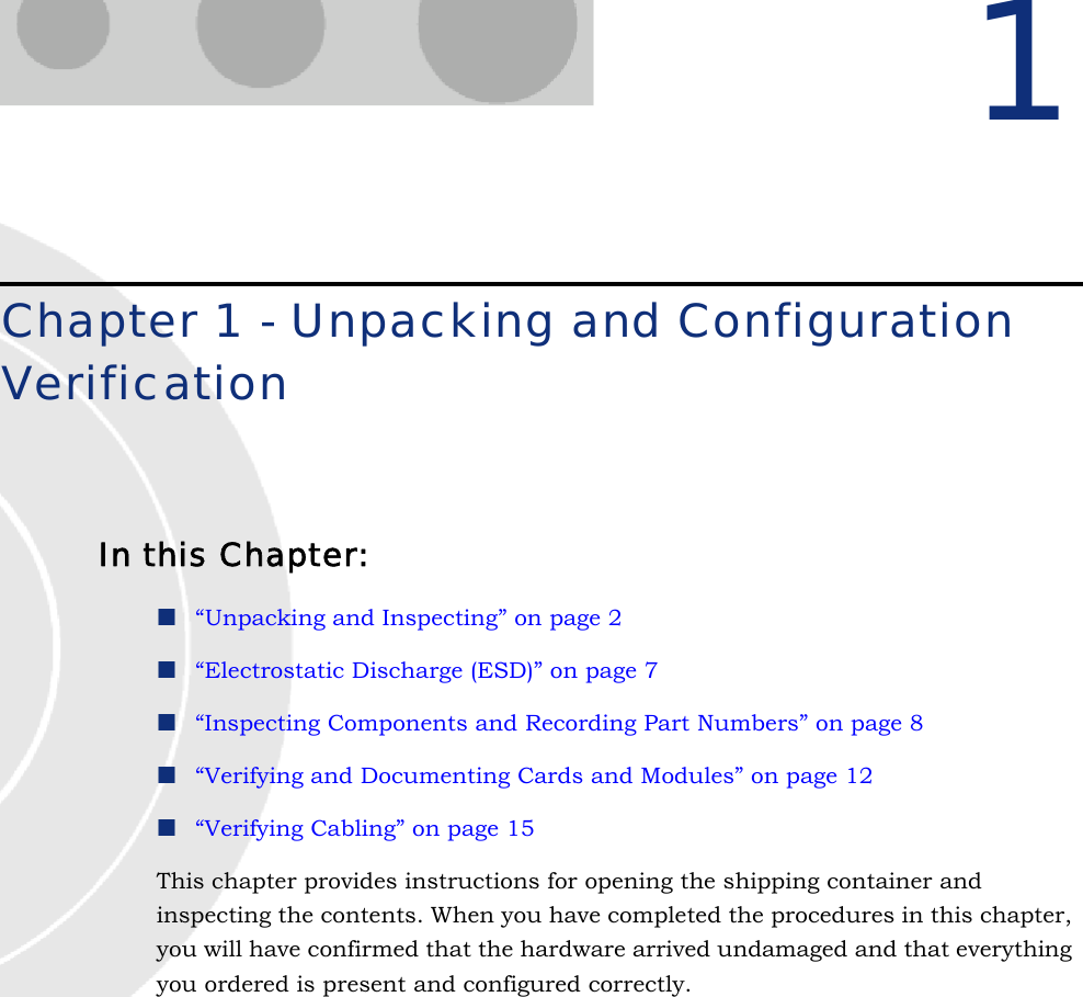
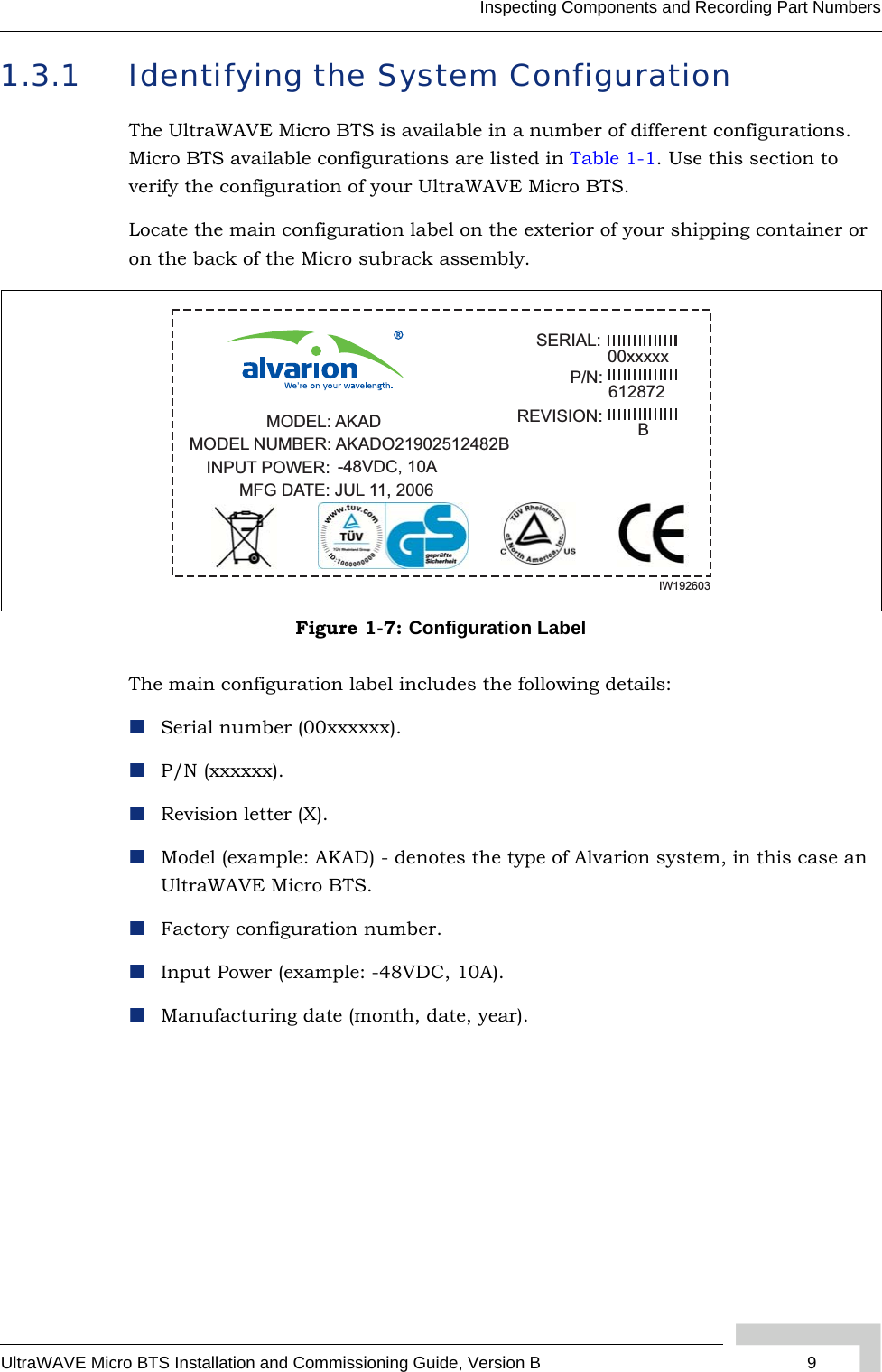
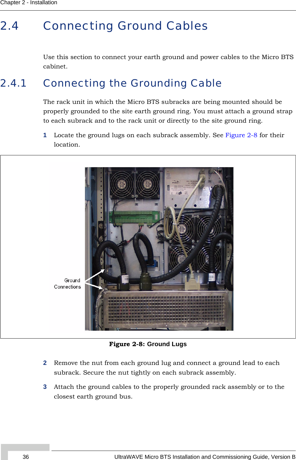
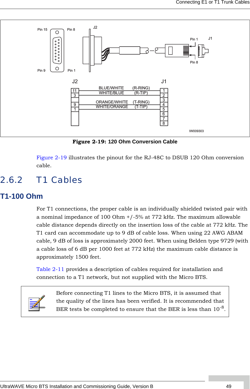
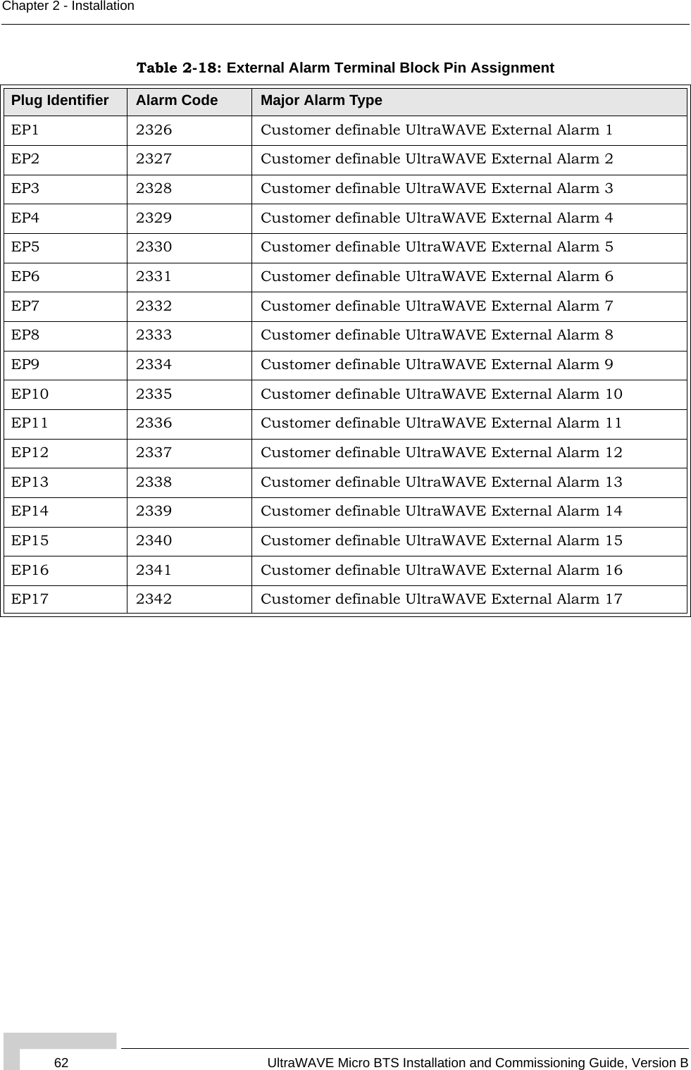
![UltraWAVE Micro BTS Installation and Commissioning Guide, Version B 27Mounting the Micro BTS Chassis2.2.2 Enclosure MountingThe Micro BTS chassis should be mounted on a concrete pad of sufficient density to support the weight of the cabinet assembly. Alignment pins may be installed in the concrete pad at the locations provided in Figure 2-4. The alignment pins should be 0.5 inches (1.27 cm) in diameter and protrude from 4.1 inches to 4.4 inches (10.41 cm to 11.18 cm) from the concrete pad.Enough clearance should be provided from the front and back of the cabinet to fully open the doors. This requires at least 24 inches (61 cm) from the front and rear doors. The minimum clearance required on either side of the cabinet is 4.5 inches (11.4 cm) and the minimum clearance required below the cabinet is 1.8 inches (4.59 cm). The mounting site should also have ample clearance for the trunk and antenna cables to be attached to the connectors at the top of the cabinet.The required footprint for your cabinet installation must be at least 73.5 inches (186.7 cm) by 31.5 inches (80 cm). Be sure there is sufficient airflow around the unit.Figure 2-4: Cabinet FootprintRubber feetMounting holeM16-2 x4 places20.898 in. [53.08 cm]22.63 in. [57.48 cm]Alignment holes0.551 in. [1.40 cm]10.00 in.[25.40 cm]14.567 in.[37.00] cmIW021301](https://usermanual.wiki/ADC-Telecommunications/AKAD19/User-Guide-723035-Page-43.png)
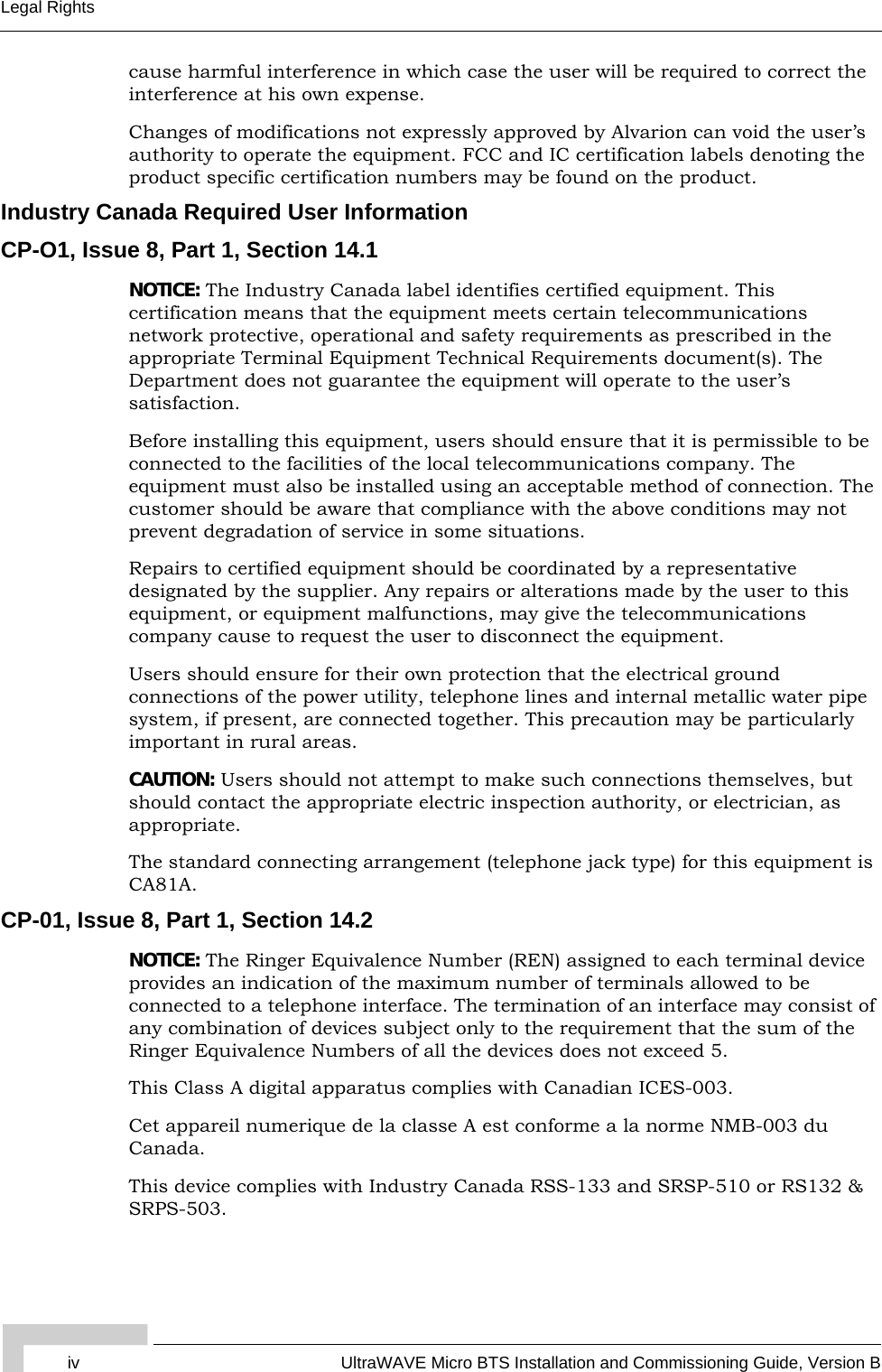
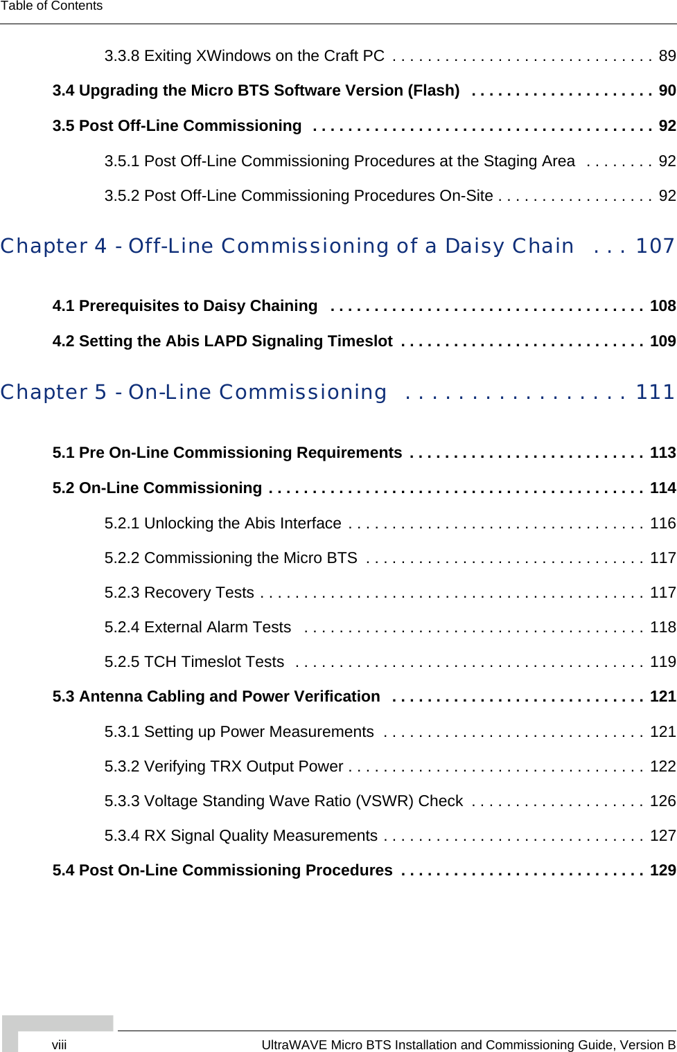
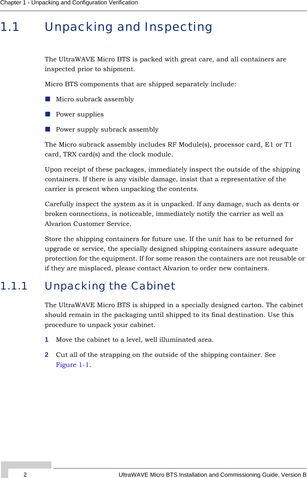
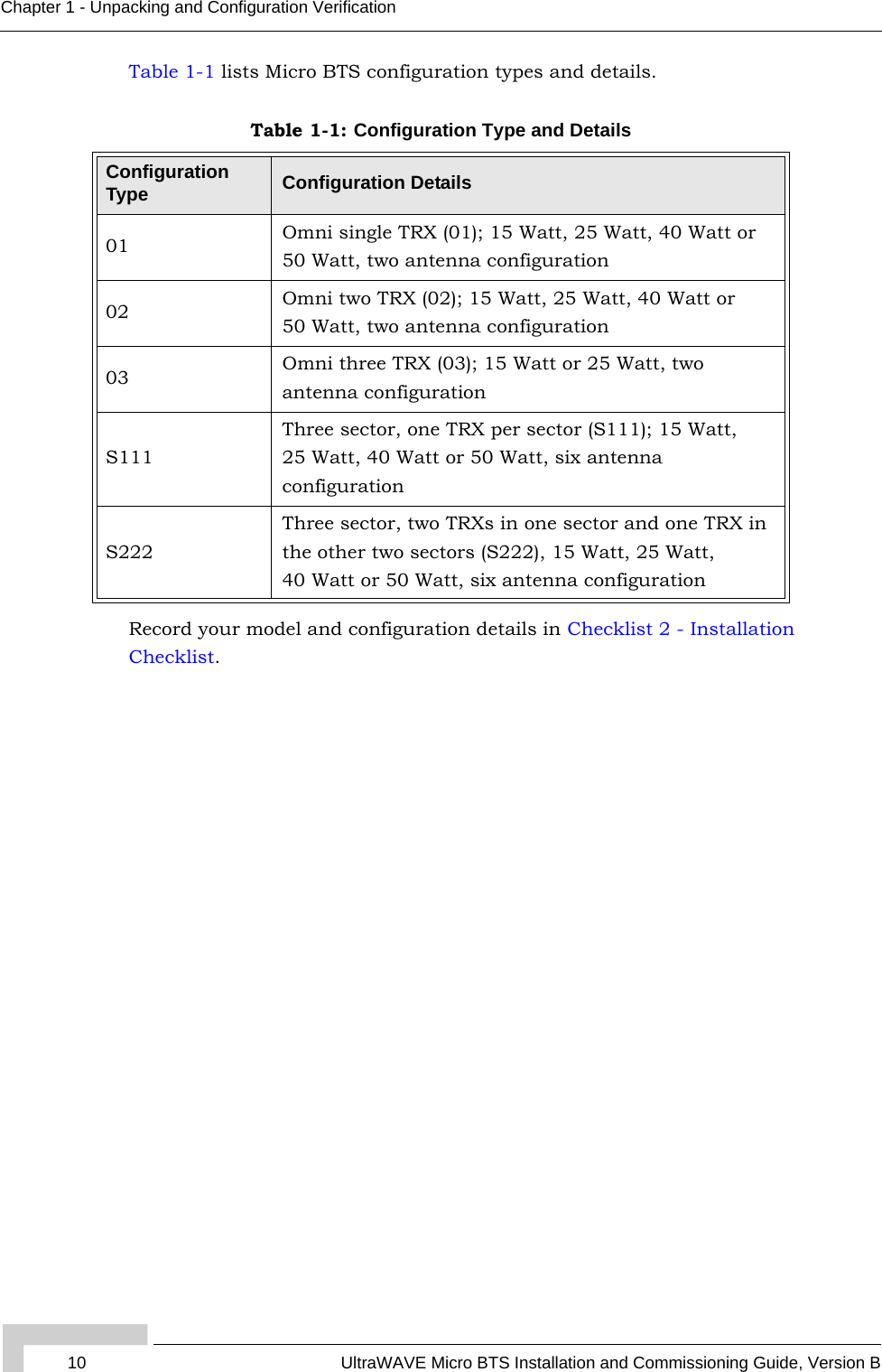
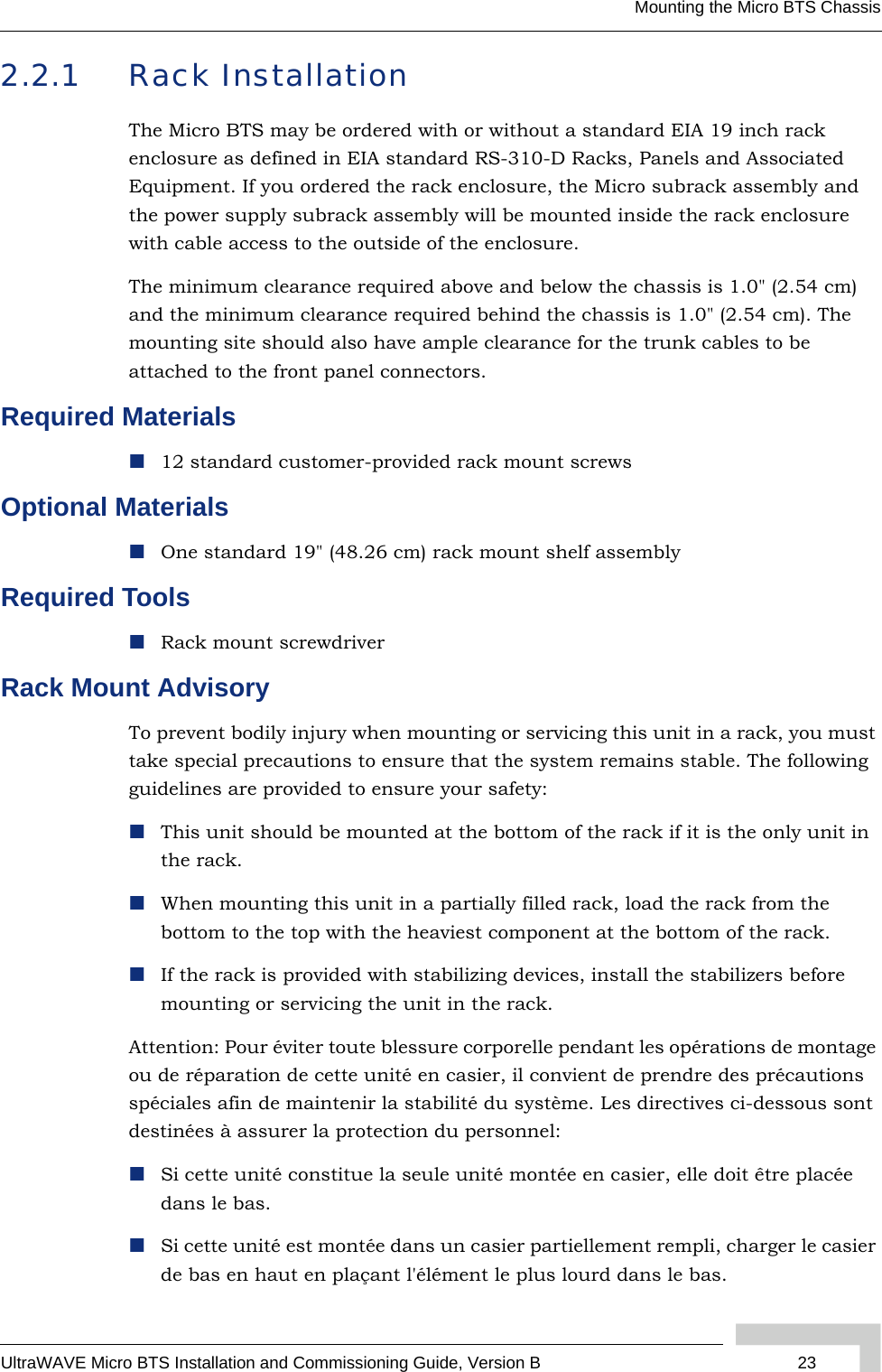
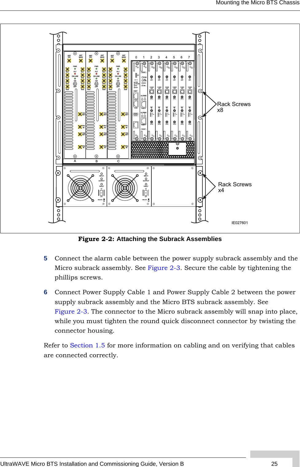
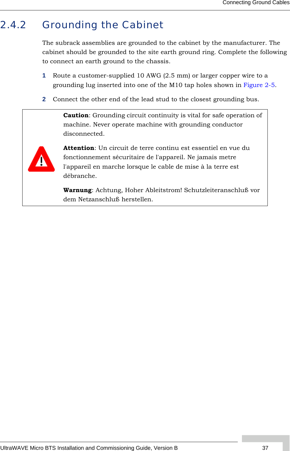
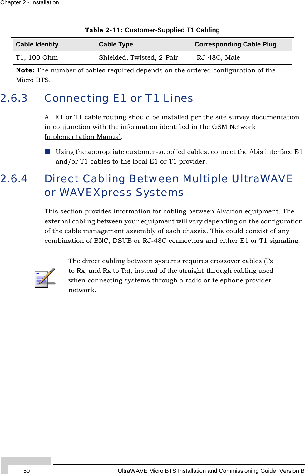
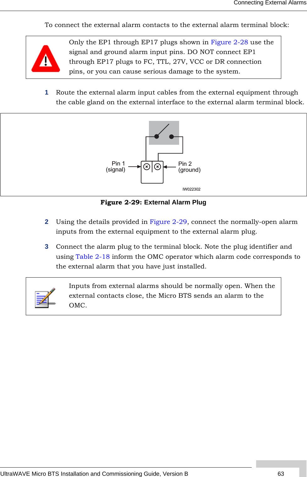
![28 UltraWAVE Micro BTS Installation and Commissioning Guide, Version BChapter 2 - InstallationThe cabinet is mounted on casters and may be carefully moved from the unpacking site to its final mounting location. The cabinet has four rubber feet which will raise the cabinet off of the casters. The dimensions for the engagement height of the rubber feet is shown in Figure 2-1. If you have alignment pins mounted in your concrete pad, use the procedure in this section.If you do not have the alignment pins, Figure 2-5 illustrates the location of eight M10 tap holes which may be used for additional mounting studs, eye hooks or angle brackets for securing the Micro BTS cabinet in its final location.Figure 2-5: Cabinet Dimensions• Make sure the ambient temperature around the unit (which may be higher than the room temperature) is within the specified limit.• Make sure there is sufficient airflow around the unit.• Make sure electrical circuits are not overloaded - consider the nameplate rating of all the connected equipment, and make sure you have over current protection.• Make sure the equipment is properly grounded.• Make sure no objects are placed on the top of the unit.22.280 in.[56.59 cm]20.547 in.[52.19 cm]Tapped holeM10-1.5 x4 places19.780 in.[50.24 cm]40.904 in.[103.90 cm]0.868 in. [2.21] cmCabinet (side)Cabinet (top)Tapped holeM10-1.5x4 placesIW021302](https://usermanual.wiki/ADC-Telecommunications/AKAD19/User-Guide-723035-Page-44.png)


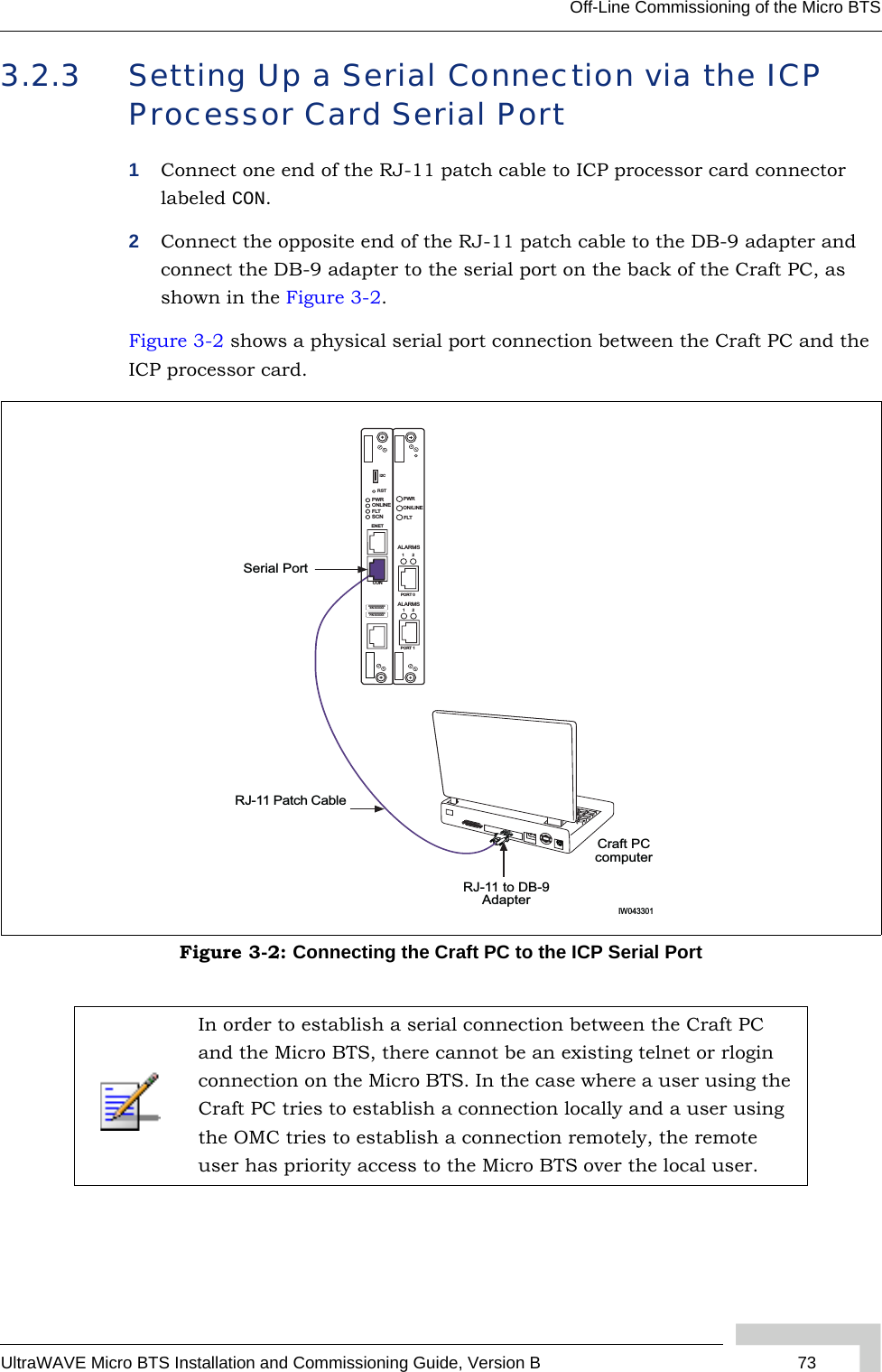
![72 UltraWAVE Micro BTS Installation and Commissioning Guide, Version BChapter 3 - Off-Line CommissioningIf you get an error message, or if the XWindows environment does not allow you to create new XWindows, stop the Craft PC environment by pressing [ALT-F4] and restart the environment.The XWindows environment now starts.3.2.2 Connecting the Craft PC to the ICP Processor CardYou will be making two connections from the Craft PC to the ICP processor card. The first is a slow-speed serial connection used for checking the software version installed on the card, verifying boot parameters and monitoring test results. The second is a faster Ethernet connection used for opening telnet sessions with the ICP. Telnet sessions are required for downloading software to the ICP. The serial and Ethernet connections are both required to configure and test the Micro BTS.Required HardwareThe following hardware is required to connect the Craft PC to the ICP processor card through an Ethernet and serial connection. Note that this hardware is supplied with the Craft PC:One Windows 2000, NT or XP compatible Ethernet portOne 3 meter standard RJ-11 patch cableOne 3 meter standard Ethernet crossover cableOne RJ-11 to DB-9 adapterBefore starting, set the xterm window to its maximum width. This prevents wordwrap.](https://usermanual.wiki/ADC-Telecommunications/AKAD19/User-Guide-723035-Page-88.png)
![UltraWAVE Micro BTS Installation and Commissioning Guide, Version B 75Off-Line Commissioning of the Micro BTSESelect OK to connect to the processor card. At this time, you will not see a prompt. Proceed to Section 3.2.4 to power on the chassis.If you do not have the Hyper Terminal application, you can open a serial session in the Craft PC application. In an Xterm window, type:build@craftpc:~> cu -l ttyS0 [ENTER]Connected.Figure 3-3: Serial Session Properties](https://usermanual.wiki/ADC-Telecommunications/AKAD19/User-Guide-723035-Page-91.png)
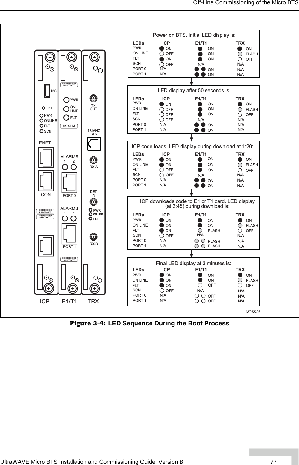
![78 UltraWAVE Micro BTS Installation and Commissioning Guide, Version BChapter 3 - Off-Line Commissioning3When the sequence is completed, verify that the LEDs appear as shown in Table 3-1.4If your LEDs appear as described above, you have completed the LED power up tests.5If your LEDs do not appear as described above, you can either:Refer to the GSM Field Maintenance Guide for troubleshooting proceduresContact Customer Service6You can monitor the status of the boot process using the serial session opened in Section 3.2.3.Once the LEDs on the processor cards have reached their final online status, press the [ENTER] key. The prompt now changes to the following:bts->Table 3-1: Normal LED Indications LED DescriptionSCN Green LED, lit when processor card is operational.PWRGreen LED, lit when card has power supplied.The PWR LED of the ICP and E1 or T1 cards will be lit after all cards have completed the boot-up process.ON LINEGreen LED, lit when card is on-line, and card BOOT process has been performed successfully.The On-LINE LED of the ICP and E1 or T1 cards will be lit after all cards have completed the boot-up process.The TRX cards will not go on-line until they are unlocked by the OMC operator.FLTRed LED, lit when card detects a fault or is not downloaded.FLT LEDs will be lit on the TRX cards until their code is downloaded.For more information about these unsuccessful power-up cases and corrective actions to be taken upon unsuccessful power up, refer to the GSM Field Maintenance Guide.](https://usermanual.wiki/ADC-Telecommunications/AKAD19/User-Guide-723035-Page-94.png)
![UltraWAVE Micro BTS Installation and Commissioning Guide, Version B 79Off-Line Commissioning of the Micro BTS3.2.5 Configuring Boot ParametersIn this section, you verify the boot parameters and change them if necessary. There are two reasons to change boot parameters:If they are configured incorrectly, you must set them to the values shown here.If your system is connected to the Ethernet, you must set the IP address to support the Craft PC IP address 172.16.80.43. To make a connection with the Craft PC, set the processor card IP address to 172.16.80.42:fffff000.After changing the boot parameters, the Micro BTS must be rebooted before the changes take effect.1If not already done, establish serial communications with the Micro BTS as described in Section 3.2.3. If the Micro BTS starts rebooting endlessly, refer to the GSM Craft PC Guide for corrective measures. If the Micro BTS boots normally, type:bts-> bootChange [ENTER]2A list of boot parameters appears. Edit the parameter values using the commands in Table 3-2.Figure 3-5 shows the default bootChange parameters for the ICP processor card. Table 3-2: Changing Boot ParametersCommand Action[ENTER] Accepts the current parameter value and proceeds to the next parameter.. [ENTER] Erases the current parameter value and proceeds to the next parameter.- [ENTER] Returns to the previous parameter.[CTRL][d] Aborts all changes and reverts to the current values.](https://usermanual.wiki/ADC-Telecommunications/AKAD19/User-Guide-723035-Page-95.png)
![80 UltraWAVE Micro BTS Installation and Commissioning Guide, Version BChapter 3 - Off-Line Commissioning3For the new parameters to take effect, reboot the Micro BTS by pressing the key combination [CTRL][x].'.' = clear field; '-' = go to previous field; ^D = quit boot device : motfcc processor number : 0 host name : craftpc file name : /home/target/vxWorks inet on ethernet (e) : 172.16.80.42:fffff000 inet on backplane (b): host inet (h) : 172.16.80.43 gateway inet (g) : user (u) : target ftp password (pw) (blank = use rsh): flags (f) : 0x0 target name (tn) : bts startup script (s) : /home/target/bsxstart.ppc other (o) : motfcc value = 0 = 0x0 bts-> Figure 3-5: Boot Parameters for ICP Processor CardYou must edit the boot parameters to contain EXACT values, or the equipment will not bootup properly.](https://usermanual.wiki/ADC-Telecommunications/AKAD19/User-Guide-723035-Page-96.png)
![82 UltraWAVE Micro BTS Installation and Commissioning Guide, Version BChapter 3 - Off-Line CommissioningEstablishing a Telnet Communications Session over Ethernet1Start a new Xterm window in the Craft PC environment.2Establish a telnet communications session by typing:build@craftpc:-> telnet iwbox [ENTER]3The Craft PC prompt now changes to bts->. This prompt verifies that the telnet session can be established. If this is not the case, verify the Ethernet wiring and retry. Terminating a Telnet Communications Session over EthernetAfter verifying that a telnet communications session can be established, terminate the telnet session as follows.1Activate the Xterm window in which the telnet communications session was established.2To terminate the telnet session, type in the Xterm window containing the telnet session:bts-> logout [ENTER]3The return message should read Connection closed by foreign host and the prompt changes back to build@craftpc->. The telnet session has now been terminated.If the Craft PC hangs when attempting to establish a telnet session, press the key combination [CTRL][c] to abort the failed connection. Check the boot parameters and repeat the connection procedures. Also verify that the Craft PC host table contains the hostname of your equipment in reference to the default IP address.Once a telnet session has been established between the Craft PC and the processor card, it must be terminated before the Craft PC is powered off. Failure to do this will result in a hung connection on the BSS system.](https://usermanual.wiki/ADC-Telecommunications/AKAD19/User-Guide-723035-Page-98.png)
![UltraWAVE Micro BTS Installation and Commissioning Guide, Version B 83Software Verification using Craft PC3.3 Software Verification using Craft PCIn this section, you use the Craft PC to verify the software configuration and other aspects of the Micro BTS operation. It is assumed that you have:Made the physical Craft PC connections to the processor cardAn active serial session3.3.1 Verifying the Current Software Version and Patch Level1If not already done, establish serial communications with the Micro BTS as described in Section 3.2.3. 2After the bts-> prompt appears, verify the current software version and patch level by typing:bts-> iwversion [ENTER]BTS code version: iw07_00.ZZZ Release number: 7.0 ABIS version: 1.1 Packages Installed: Encryption: A5/1 Patches Installed: patch<#> <file directory> <patch size> <iw07_00.ZZZ>The current software version is displayed, represented above by the parameter iw07_00.ZZZ. This number should correspond to the software version detailed in the release notes included with the CD-ROM. Keep this number for your records.3Verify under Patches Installed: that the most current patch is installed, if applicable. Refer to the GSM Craft PC Guide for procedures to install required patches. If you are unsure if you require software patches, contact your Level 2 support representative for additional assistance.The following section describes procedures performed using the Craft PC. For more information about the Craft PC, refer to the GSM Craft PC Guide.](https://usermanual.wiki/ADC-Telecommunications/AKAD19/User-Guide-723035-Page-99.png)
![84 UltraWAVE Micro BTS Installation and Commissioning Guide, Version BChapter 3 - Off-Line Commissioning3.3.2 Checking the Flash Version NumberIn order to verify that the correct software build is loaded into flash memory, go to your serial Xterm window and type:bts-> printConfigBlocks [ENTER]The screen displays information relating to the flash images. Figure 3-7 shows Image 0, Image 1 and Image 2 from the ICP card configuration.The ICP configuration states Current Image = N where N is either 0 or 1. The flash version have lines in the format:iw07_00.ZZZwhere iw07_00.ZZZ indicates the flash version.If the displayed software version number does not coincide with the software version being run on the network for which this Micro BTS is going to be used, refer to Section 3.4 for instructions on how to install a different software version on the processor card.**** Current Image = 1 ************ Image 0 ********* Image IW version : iw07_00.010 Image creation date: 04/15/02 13:44 Image crc : 1ff03d8d******** Image 1 ********* Image IW version : iw7_00.012 Image creation date: 04/09/02 12:07 Image crc : e3b05e8c******** Image 2 ********* Image IW version : iw07_00.010 Image creation date: 04/09/02 12:07 Image crc : e3b05e8cFigure 3-7: Determining the Flash Version on an ICP Processor Card](https://usermanual.wiki/ADC-Telecommunications/AKAD19/User-Guide-723035-Page-100.png)
![UltraWAVE Micro BTS Installation and Commissioning Guide, Version B 85Software Verification using Craft PCThe flash version number should be iw07_00.012 or higher for BTS TRX POST diagnostics to be able to run. If it is not, the flash version number will have to be changed and the Micro BTS rebooted.3.3.3 Running E1 or T1 POST Diagnostics1Disconnect all E1 and/or T1 lines from the BTS. This ensures that no Abis connection exists. If an Abis connection does exist, the TRX POST might not run properly.2Wait until the bts-> prompt appears, and type: bts-> reboot [ENTER]This action reboots the Micro BTS. The VxWorks kernel is started, several E1 or T1 trunk card tests run sequentially, and the results of each test are listed as PASSED/FAILED. Only if all seven tests passed successfully will the E1 or T1 POST diagnostics be considered successful. The E1 or T1 POST results will be displayed after the boot process has been completed.Flash Image 2 is reserved for Alvarion Customer Service use ONLY. The coding for the E1 or T1 trunk card, its modules and scripts generically refer to the E1 or T1 trunk card objects as “E1”, whether the corresponding ports are configured as E1 or T1.1 (e1diag) E1 CARD in SLOT 1: STARTING POST/OFFLINE Test2 (e1diag) testsPtr 0xffb33ab4 testsPtr[0] 0x53 (e1diag) testsPtr 0xffb33ab4 testsPtr[0] 0x5 result 0x0 i 14 (e1diag) E1(1) TID01: Initialize Peripheral Registers: PASSED5 (e1diag) testsPtr 0xffb33ab4 testsPtr[0] 0x5 result 0x0 i 26 (e1diag) E1(1) TID02: Peripheral Register Test: PASSED7 (e1diag) testsPtr 0xffb33ab4 testsPtr[0] 0x5 result 0x0 i 38 (e1diag) E1(1) TID03: Framer Register Test: PASSED9 (e1diag) testsPtr 0xffb33ab4 testsPtr[0] 0x5 result 0x0 i 410 (e1diag) E1(1) TID04: VME to CPU FIFO Flag Test: PASSED11 (e1diag) testsPtr 0xffb33ab4 testsPtr[0] 0x5 result 0x0 i 512 (e1diag) E1(1) TID05: Initialize Time/Space sw Chip: PASSED13 (e1diag) testsPtr 0xffb33ab4 testsPtr[0] 0x5 i 614 (e1diag) E1 CARD in SLOT 1: COMPLETED POST/OFFLINE Test: PASSEDFigure 3-8: E1 or T1 POST Results](https://usermanual.wiki/ADC-Telecommunications/AKAD19/User-Guide-723035-Page-101.png)
![86 UltraWAVE Micro BTS Installation and Commissioning Guide, Version BChapter 3 - Off-Line Commissioning3Figure 3-8 shows the E1 or T1 POST results that would appear if the E1 or T1 POST diagnostics ran successfully on the E1 or T1 trunk card in slot 1. The format for each diagnostic line is:[line number][action][E1 or T1 number][test number][test description][test result]In the case of an error, a FAILED message would appear following the test that failed. In addition, the following message would be displayed in Line 8:E1 CARD in SLOT 1: COMPLETED POST/OFFLINE Test: FAILED3.3.4 Running TRX POST DiagnosticsThis section explains how to use the Craft PC to run the TRX POST diagnostics on the Micro BTS.1Verify that you can establish and terminate a telnet communications session as described in Section 3.2.7.2Verify that you can establish a serial connection as described in Section 3.2.3.3After the Micro BTS has booted up and the E1 or T1 POST has run during the boot process, the TRX POST diagnostics can be initiated. Type:bts-> runtrxpost [ENTER]4A set of TRX POST diagnostic tests run sequentially over the Ethernet connec-tion and the results of each test will be listed as PASSED/FAILED. Only if all tests pass successfully will the TRX POST diagnostics be considered successful. The TRX POST results will be displayed after the boot process has been completed.If an E1 or T1 trunk card fails the POST diagnostics, remove the failed card and return it to Alvarion along with its test results file. The defective card needs to be replaced with a new one, and POST diagnostics should be run again on the new card.The TRX ON LINE LED flashes continuously when TRX POST diagnostics are being run and does not stop flashing until the Micro BTS is rebooted. The flashing LED can be used as a reminder to reboot the system after successfully completing the TRX POST and other diagnostics.](https://usermanual.wiki/ADC-Telecommunications/AKAD19/User-Guide-723035-Page-102.png)
![UltraWAVE Micro BTS Installation and Commissioning Guide, Version B 87Software Verification using Craft PCThe format for each diagnostic line is:[line number][action][TRX number][test number][test description][test result]For example:14 (Diag) ISR(2) TF22: Test Basic op of VME/RTP FIFOs: PASSED where:Figure 3-9 shows the TRX POST results for a TRX in slot 2 of the Micro BTS and shows that the TRX POST diagnostics ran successfully on the TRX card.Table 3-3: Description of the TRX POST Results Line Entry Description14 Line numberDiag Diagnostic test being runISR(2) ISR TRX 2 is being testedTF22 Test number Test Basic op of VME/RTP FIFOs Test descriptionPASSED Indicates that the TRX passed this testSerialNumber: 16 (txpostf) STARTING BTS FUNCTIONAL CODE... a3 a8 0 0 1 0 20 4a SerialNumber: a3 28 0 0 1 0 20 a0 SerialNumber: a3 2d 0 0 1 0 20 4b SerialNumber: a3 50 1 0 1 0 20 54 SerialNumber: a3 95 0 0 1 0 20 ed SerialNumber: a3 a9 0 0 1 0 20 7d 17 (Diag ) TRX CARD IN SLOT 2 : STARTING TRX POST OFFLINE Test 18 (Diag ) ISR(2) tf 5 Test VME Access ....................... PASSED 19 (Diag ) ISR(2) tf 12 Load FPGA (TDM) ....................... PASSED 20 (Diag ) ISR(2) tf 13 Load FPGA (RC) ........................ PASSED 21 (Diag ) ISR(2) tf 16 Load DSP (Coder) ...................... PASSED 22 (Diag ) ISR(2) tf 17 Load DSP (Equalizer) .................. PASSED 23 (Diag ) ISR(2) tf 18 Load DSP (Modulator) .................. PASSED 24 (Diag ) ISR(2) tf 19 Ping DSP (Coder) ...................... PASSED 25 (Diag ) ISR(2) tf 20 Ping DSP (Equalizer) .................. PASSED 26 (Diag ) ISR(2) tf 46 Ping DSP (Modulator) .................. PASSED 27 (Diag ) ISR(2) tf 22 DSP Diag Mode ON (Coder) .............. PASSED 28 (Diag ) ISR(2) tf 27 Test External RAM (Coder) ............. PASSED 29 (Diag ) ISR(2) tf 24 DSP Diag Mode ON (Equalizer) .......... PASSED 30 (Diag ) ISR(2) tf 28 Test External RAM (Equalizer) ......... PASSED 31 (Diag ) ISR(2) tf 47 Test Mdltr DSP Serial Bus loopback .... PASSED 32 (Diag ) ISR(2) tf 30 Test TDM Control Store RAM ............ PASSED 33 (Diag ) ISR(2) tf 34vvvvvvvvvvvvTest TDM Loop-back .................... PASSED 34 (Diag ) ISR(2) tf 36 Test RC to Equalizer Serial Bus ....... PASSED 35 (Diag ) ISR(2) tf 39 Test Coder to RC Serial Bus ........... PASSED 36 (Diag ) ISR(2) tf 40 Test Equalizer To Coder Serial Bus .... PASSED 37 (Diag ) ISR(2) tf 43 Test Tuner Register Read/Write ........ PASSED lowChannel = 128, highChannel = 251 38 (Diag ) ISR(2) tf 41 Test Channel Synthesizers ............. PASSED 39 (Diag ) ISR(2) tf 48 Test Power Ramp External RAM .......... PASSED 40 (Diag ) ISR CARD IN SLOT 2 : COMPLETED POST OFFLINE Test : PASSEDFigure 3-9: TRX POST Results](https://usermanual.wiki/ADC-Telecommunications/AKAD19/User-Guide-723035-Page-103.png)
![88 UltraWAVE Micro BTS Installation and Commissioning Guide, Version BChapter 3 - Off-Line Commissioning3.3.5 Reviewing POST ResultsThis section explains how to review E1 or T1 POST and TRX POST diagnostics results after POST has been completed on the Micro BTS.1Turn on basic logging by typing:bts-> log_none2To display the most current E1 or T1 and TRX POST results after POST has been completed, type:bts-> postReportE1Trx [ENTER]Figure 3-10 displays a summary of the E1 or T1 and TRX POST results that will be displayed (note that some tests may not run).The following procedure assumes that E1 or T1 and TRX POST have just been completed on the selected Micro BTS and a serial connection is still active between the Craft PC and the Micro BTS. If this is not the case, reboot the Micro BTS and run POST again.This will result in extra output being displayed in the xterm, subsequent commands entered may run into several lines as a result of the extra logs.bts:> postReportE1Trx******************* E1 DIAGNOSTICS REPORT ********************************************************************************Slot:1E1(1)TID01: Initialize Peripheral Registers : PASS E1(1)TID02: Peripheral Register Test : PASS E1(1)TID03: Framer Register Test : PASS E1(1)TID04: VME to CPU FIFO Flag Test : PASS E1(1)TID05:Initialize Time/Space sw Chip : PASS E1(1)TID06: Software Download Test : Not-Run E1(1)TID07: Memory Test : Not-Run E1(1)TID08: CPM download Test : Not-Run E1(1)TID09: TRAU DSP Test : Not-Run E1(1)TID10: Cross Connect Test : Not-Run ******************************************************************************** TRX DIAGNOSTICS REPORT *******************************************************************************Slot 2-------------------------------------------------------------All Tests PASSED*************************************************************value=58=0x3a='=”bts:>Figure 3-10: Reviewing E1 or T1 and TRX POST Results](https://usermanual.wiki/ADC-Telecommunications/AKAD19/User-Guide-723035-Page-104.png)
![UltraWAVE Micro BTS Installation and Commissioning Guide, Version B 89Software Verification using Craft PC3.3.6 Rebooting the Micro BTS after Running POST1In the serial communications window, type:bts-> reboot [ENTER]This action places the TRX in an on-line and operational state.2Reconnect all E1 or T1 lines to the Micro BTS.3.3.7 Terminating Serial Communications with the Micro BTS1To terminate the serial communications between the Craft PC and the BTS in an xterm, type:bts-> ~.2After a few seconds the returned message should read Disconnected, and the display will revert back to build@craftpc:-> prompt.3Close the Hyper Terminal window if you are using Hyper Terminal for serial communications.3.3.8 Exiting XWindows on the Craft PCThis section explains how to close XWindows running the Windows 2000/XP operating system on the Craft PC.Left click the X in the upper right hand corner of your XWindows window.There are five tests that are not run but show up in the results section when the user manually retrieves the POST results. These tests are not displayed when running POST by rebooting the BTS. They are:• T1(1) TID06: Software Download Test : Not-Run • T1(1) TID07: Memory Test : Not-Run • T1(1) TID08: CPM Download Test : Not-Run • T1(1) TID09: TRAU DSP Test : Not-Run • T1(1) TID10: Cross Connect Test : Not-Run If you are going to perform the Racal tests described in the GSM Radio Test Procedures at this time, ensure that you have rebooted the chassis. Also, leave the Craft PC connected to the ICP card and a serial communications session active.](https://usermanual.wiki/ADC-Telecommunications/AKAD19/User-Guide-723035-Page-105.png)
![90 UltraWAVE Micro BTS Installation and Commissioning Guide, Version BChapter 3 - Off-Line Commissioning3.4 Upgrading the Micro BTS Software Version (Flash)Use this procedure if the procedures in Section 3.3.1 indicate that you need to update your software version.The Micro BTS stores its release software in Flash RAM. This section explains how to upgrade the Micro BTS Flash boot image locally using the Craft PC.1Power up the Craft PC and start the XWindows environment. For Craft PC power-up procedures, refer to Section 3.2.2. For XWindows start-up procedures, refer to Section 3.2.1.2Verify that a telnet session can be established with the Micro BTS. In an Xterm window, type:build@craftpc:~> telnet iwbox [ENTER]3If the Ethernet connection is setup correctly, then the Craft PC returns the vxWorks bts-> prompt. If this is not the case, refer to Section 3.2.7 for setup procedures.4Once the Ethernet connection has been tested, terminate the telnet session by typing:bts-> logout [ENTER]The Craft PC returns the build@craftpc:~> prompt. 5Establish a serial session with the Micro BTS. Refer to Section 3.2.3.6Change the working directory to the directory containing the new software version you wish to upgrade to the Micro BTS, type:cd “/home/build/iw07_00.ZZZ/iwlib/platform/bspppc” [ENTER]The iw07_00.ZZZ parameter represents the new software version you wish to load on the Micro BTS.In order to update the BTS Flash boot image locally using the Craft PC, the Craft PC hard drive must contain the software version (Flash boot image) to be installed. If the required release is not installed on your Craft PC, use the procedures in the GSM Craft PC Guide to install it.](https://usermanual.wiki/ADC-Telecommunications/AKAD19/User-Guide-723035-Page-106.png)
![UltraWAVE Micro BTS Installation and Commissioning Guide, Version B 91Upgrading the Micro BTS Software Version (Flash)7To find out which Flash image in which the current software version resides, type:bts-> getCurrentImage [ENTER] value = 0 = 0x08Make a note of the returned value, which might be either 0 or 1. This is the active image in which the current Flash resides. The binary opposite of this value will be used to load the new Flash in the following steps:If Current Image Value is 0 (value = 0 = 0x0)9Load the new Flash in the inactive image. At the bts-> prompt, type:bts-> writeFlashImage “btsflash.bin”, 1 [ENTER]10 This takes about one minute. When the bts-> prompt returns, set the inactive image containing the new Flash as the active or current image, type:bts-> setImageCurrent 1 [ENTER]11 Reboot the Micro BTS for the new Flash image to take effect by pressing the key combination [CTRL][x].If Current Image Value is 1 (value = 1 = 0x1)12 Load the new Flash in the inactive image. At the bts-> prompt, type:bts-> writeFlashImage “btsflash.bin”, 0 [ENTER]13 This takes about one minute. When the bts-> prompt returns, set the inactive image containing the new Flash as the active or current image, type:bts-> setImageCurrent 0 [ENTER]14 Reboot the Micro BTS for the new Flash image to take effect by pressing the key combination [CTRL][x].The Flash boot image has been upgraded to the new software version and set as the default. Flash Image 2 is reserved for Alvarion Customer Service use ONLY.](https://usermanual.wiki/ADC-Telecommunications/AKAD19/User-Guide-723035-Page-107.png)
![UltraWAVE Micro BTS Installation and Commissioning Guide, Version B 109Setting the Abis LAPD Signaling Timeslot4.2 Setting the Abis LAPD Signaling TimeslotThis procedure sets the Abis LAPD timeslot between the MSC and each Micro BTS. If the Abis timeslot is not set, it automatically defaults to 16.This procedure is optional for a star configured Micro BTS, but is required for all BTSs which will be used in a daisy chain. In this case, each Micro BTS must have its Abis timeslot set to a unique number in the chain. This information will be used by the OMC operator to configure the daisy chain. 1Ensure that the Craft PC is connected to the Micro BTS over a serial line, and that a serial connection is established. Refer to Chapter 3 - Off-Line Commissioning for instructions on how to do this.2In an Xterm window, type:bts-> getFlashE1Chan [ENTER]This displays the timeslot reserved for the Abis LAPD signalling timeslot, which is by default set to 16. To change this value, type:bts-> setFlashE1Chan <number> [ENTER]where <number> is the Abis LAPD signaling timeslot assigned to an unassigned T1 channel between 1 and 24 or to an unassigned E1 channel between 1 and 31.This procedure must be performed after the Micro BTS is tested using a Racal test set. Refer to the GSM Field Maintenance Guide for further instructions.The Abis signaling timeslot for each Micro BTS in the daisy chain must be set to a different number. For example:• Micro BTS 1 in the chain = Set timeslot 16 as the Abis timeslot• Micro BTS 2 in the chain = Set timeslot 17 as the Abis timeslot• Micro BTS 3 in the chain = Set timeslot 18 as the Abis timeslot• Micro BTS 4 in the chain = Set timeslot 19 as the Abis timeslotMake sure that this information is communicated to the OMC operator.](https://usermanual.wiki/ADC-Telecommunications/AKAD19/User-Guide-723035-Page-111.png)
![110 UltraWAVE Micro BTS Installation and Commissioning Guide, Version BChapter 4 - Off-Line Commissioning of a Daisy Chain3To double-check that the timeslot was changed, type again:bts-> getFlashE1Chan [ENTER]The new Abis signaling timeslot number should be displayed.4If the Abis signaling timeslot was changed, the Micro BTS must be rebooted. Type:bts-> reboot [ENTER]](https://usermanual.wiki/ADC-Telecommunications/AKAD19/User-Guide-723035-Page-112.png)

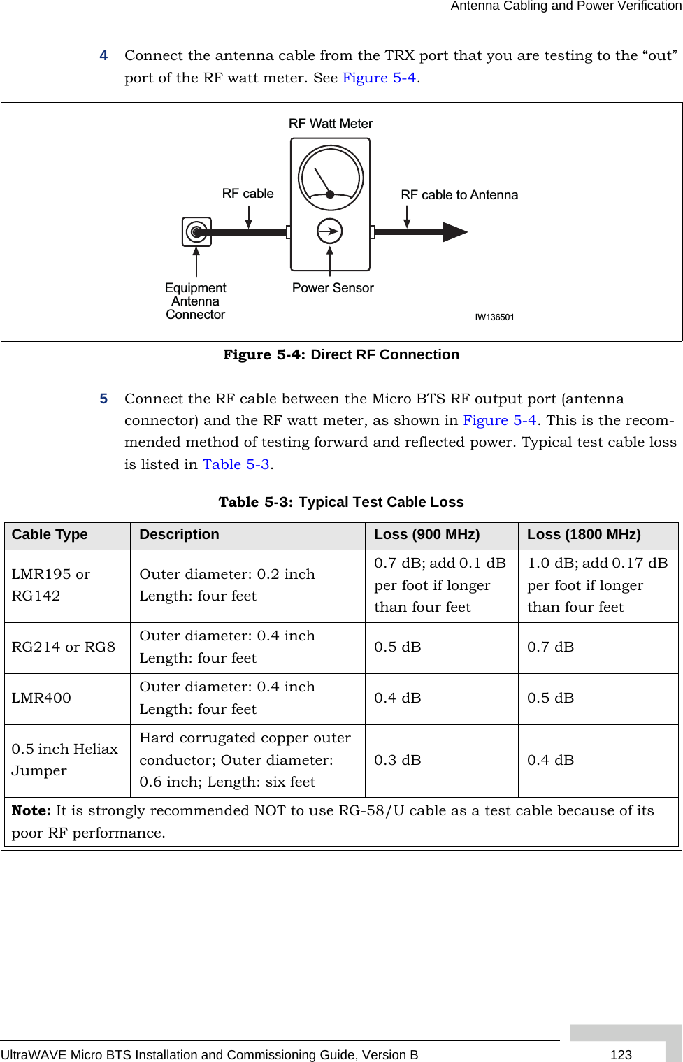
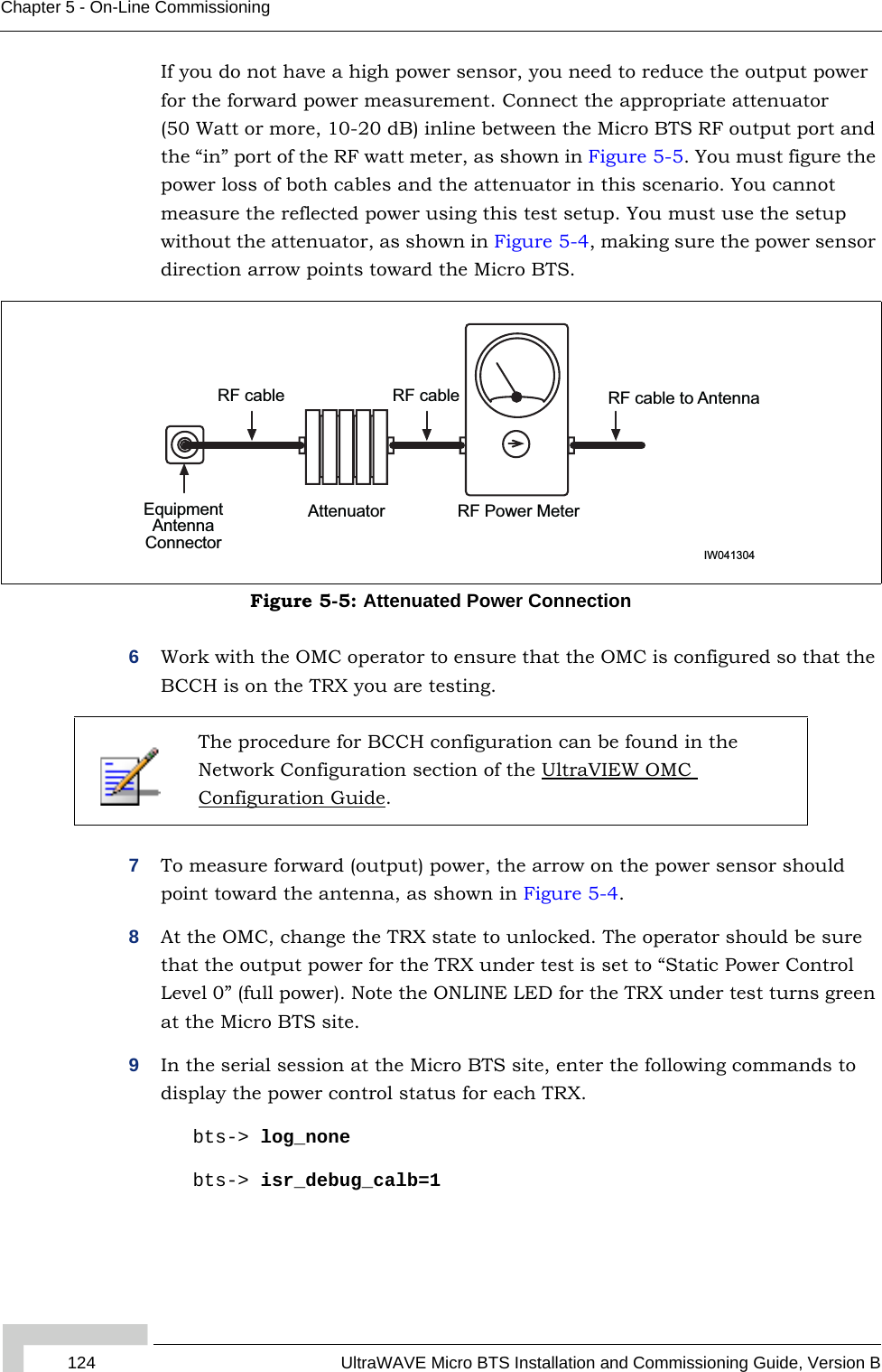
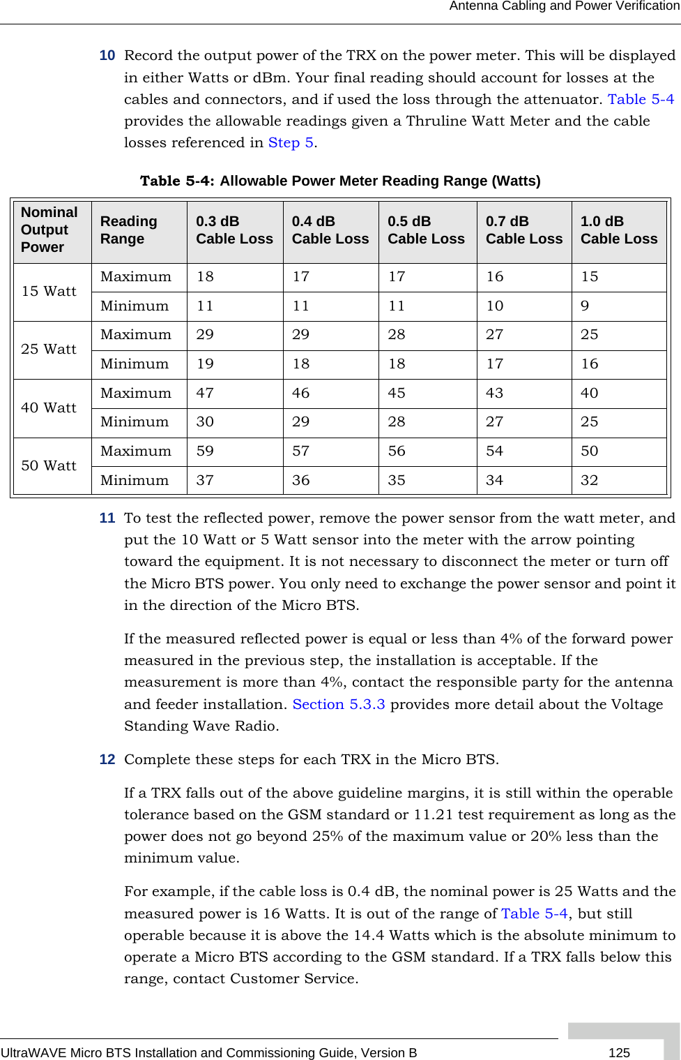
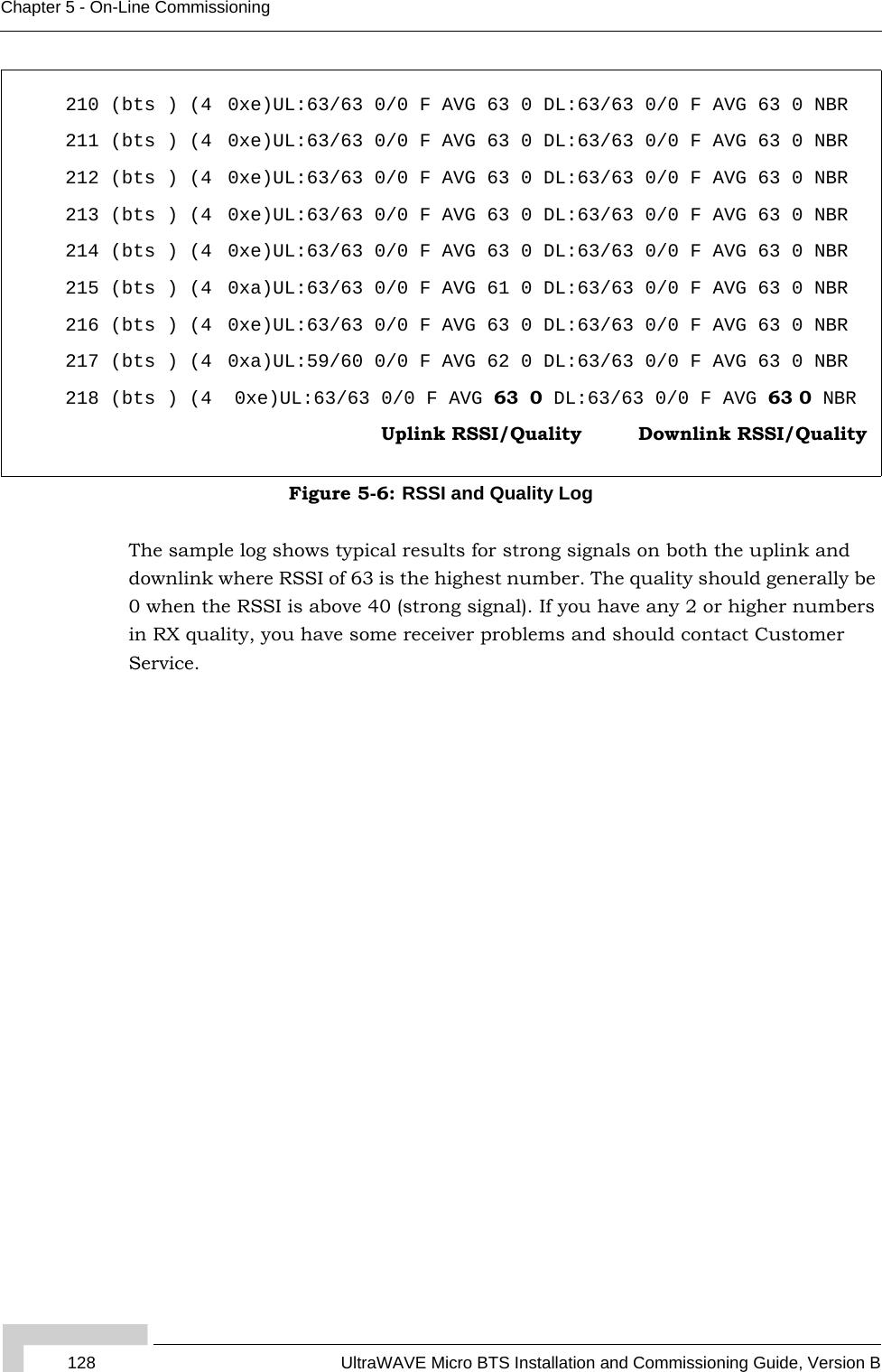
![UltraWAVE Micro BTS Installation and Commissioning Guide, Version B 127Antenna Cabling and Power Verification5.3.4 RX Signal Quality MeasurementsThe objectives of this test are to verify the performance of the Receive path of the Micro BTS and the operation of the RX module in the TRX. Before these tests can take place, the Micro BTS must be returned to its original “on air” working state with call processing possible.1From an Xterm window on the OMC, telnet to the Micro BTS to be tested, or alternatively connect directly to the Micro BTS with the Craft PC.The field technician can also open a serial session directly with the Micro BTS, and proceed to Step 4.2From the iwbox prompt find the IP address of the Micro BTS by typing:HD:iwbox-> ifShow “ppp” [ENTER]A list of PPP connections will then be displayed. Look for the IP address of the Micro BTS you will be testing. The last number of the 192.168.5.x address relates to the BtsMgr number of the Micro BTS.3From the iwbox prompt type the following to connect to the Micro BTS:HD:iwbox-> rlogin “192.168.5.x” [ENTER]If this is successful you will receive the bts-> prompt.4From the Micro BTS prompt type the following to activate the RX RSSI and quality data logging:bts-> log_none [ENTER]bts-> ho_log_on_bts [ENTER]5Place a mobile to mobile call through the Micro BTS. The RSSI and Quality for the call will be displayed, as illustrated in Figure 5-6.](https://usermanual.wiki/ADC-Telecommunications/AKAD19/User-Guide-723035-Page-129.png)