ADC Telecommunications DAS819A-4 In Building Repeater - Remote Access Unit User Manual Part 1
ADC Telecommunications Inc. In Building Repeater - Remote Access Unit Users Manual Part 1
Contents
- 1. Users Manual Part 1
- 2. Users Manual Part 2 Revised
Users Manual Part 1
LGCell Wireless
Networking System
Version 4.0
TM
®
Installation, Operation, and Reference Manual
PN 8100-40
620004-0 Rev. E

LGCell 4.0 Installation, Operation, and Reference Manual PN 8100-40
620004-0 Rev. E
This manual is produced for use by LGC Wireless personnel, licensees, and customers. The
information contained herein is the property of LGC Wireless. No part of this document
may be reproduced or transmitted in any form or by any means, electronic or mechanical,
for any purpose, without the express written permission of LGC Wireless.
LGC Wireless reserves the right to make changes, without notice, to the specifications and
materials contained herein, and shall not be responsible for any damages caused by reliance
on the material as presented, including, but not limited to, typographical and listing errors.
Your comments are welcome – they help us improve our products and documentation.
Please address your comments to LGC Wireless, Inc. corporate headquarters in San Jose,
California:
Address 2540 Junction Avenue
San Jose, California
95134-1902 USA
Attn: Marketing Dept.
Phone 1-408-952-2400
Fax 1-408-952-2410
Help Hot Line 1-800-530-9960 (U.S. only)
+1-408-952-2400 (International)
Web Address http://www.lgcwireless.com
e-mail info@lgcwireless.com
service@lgcwireless.com
Copyright © 2001-2002 by LGC Wireless, Inc. Printed in USA. All rights reserved.
Trademarks
All trademarks identified by ™ or ® are trademarks or registered trademark of LGC
Wireless, Inc. All other trademarks belong to their respective owners.

PN 8100-40 LGCell 4.0 Installation, Operation, and Reference Manual
620004-0 Rev. E
Limited Warranty
Seller warrants articles of its manufacture against defective materials or workmanship for a
period of one year from the date of shipment to Purchaser, except as provided in any warranty
applicable to Purchaser on or in the package containing the Goods (which warranty takes
precedence over the following warranty). The liability of Seller under the foregoing warranty
is limited, at Seller’s option, solely to repair or replacement with equivalent Goods, or an
appropriate adjustment not to exceed the sales price to Purchaser, provided that (a) Seller is
notified in writing by Purchaser, within the one year warranty period, promptly upon
discovery of defects, with a detailed description of such defects, (b) Purchaser has obtained a
Return Materials Authorization (RMA) from Seller, which RMA Seller agrees to provide
Purchaser promptly upon request, (c) the defective Goods are returned to Seller,
transportation and other applicable charges prepaid by the Purchaser, and (d) Seller’s
examination of such Goods discloses to its reasonable satisfaction that defects were not
caused by negligence, misuse, improper installation, improper maintenance, accident or
unauthorized repair or alteration or any other cause outside the scope of Purchaser’s warranty
made hereunder. Notwithstanding the foregoing, Seller shall have the option to repair any
defective Goods at Purchaser’s facility. The original warranty period for any Goods that have
been repaired or replaced by seller will not thereby be extended. In addition, all sales will be
subject to standard terms and conditions on the sales contract.

LGCell 4.0 Installation, Operation, and Reference Manual PN 8100-40
620004-0 Rev. E

PN 8100-40 LGCell 4.0 Installation, Operation, and Reference Manual i
620004-0 Rev. E
Table of Contents
SECTION 1 General Information . . . . . . . . . . . . . . . . . . . . . . 1-1
1.1 Purpose and Scope . . . . . . . . . . . . . . . . . . . . . . . . . . . . . . . . . 1-2
1.2 Conventions in this Manual . . . . . . . . . . . . . . . . . . . . . . . . . . 1-3
1.3 Acronyms in this Manual . . . . . . . . . . . . . . . . . . . . . . . . . . . . 1-4
1.4 Standards Conformance . . . . . . . . . . . . . . . . . . . . . . . . . . . . . 1-6
1.5 Related Publications . . . . . . . . . . . . . . . . . . . . . . . . . . . . . . . . 1-6
SECTION 2 LGCell 4.0 System Description . . . . . . . . . . . . . 2-1
2.1 System Overview . . . . . . . . . . . . . . . . . . . . . . . . . . . . . . . . . . 2-2
2.2 System Operation . . . . . . . . . . . . . . . . . . . . . . . . . . . . . . . . . . 2-5
2.2.1 Using LGCell to Increase Coverage and Capacity . . . . . . . . . 2-6
2.2.2 Using LGCell to Increase Coverage, Capacity, and
Functionality . . . . . . . . . . . . . . . . . . . . . . . . . . . . . . . . . . . . . . 2-7
2.2.3 Using LGCell to Simultaneously Support Multiple
Bands/Protocols . . . . . . . . . . . . . . . . . . . . . . . . . . . . . . . . . . . . 2-8
2.3 System Bandwidths . . . . . . . . . . . . . . . . . . . . . . . . . . . . . . . 2-11
2.3.1 800 MHz and 900 MHz Systems . . . . . . . . . . . . . . . . . . . . . 2-11
2.3.2 1800 MHz and 1900 MHz Systems . . . . . . . . . . . . . . . . . . . 2-12
2.4 System Specifications . . . . . . . . . . . . . . . . . . . . . . . . . . . . . . 2-14
2.4.1 Physical Specifications . . . . . . . . . . . . . . . . . . . . . . . . . . . . . 2-14
2.4.2 Environmental Specifications . . . . . . . . . . . . . . . . . . . . . . . . 2-15
2.4.3 Alarm LEDs . . . . . . . . . . . . . . . . . . . . . . . . . . . . . . . . . . . . . 2-15
SECTION 3 LGCell Main Hub . . . . . . . . . . . . . . . . . . . . . . . . . 3-1
3.1 LGCell Main Hub Front Panel . . . . . . . . . . . . . . . . . . . . . . . . 3-2
3.1.1 MMF Downlink/Uplink Ports . . . . . . . . . . . . . . . . . . . . . . . . . 3-3
3.1.2 Main Hub LED Indicators . . . . . . . . . . . . . . . . . . . . . . . . . . . . 3-4
3.2 LGCell Main Hub Rear Panel . . . . . . . . . . . . . . . . . . . . . . . . . 3-5
3.2.1 Main Hub Rear Panel Connectors . . . . . . . . . . . . . . . . . . . . . . 3-6
3.3 LGCell Main Hub Alarm . . . . . . . . . . . . . . . . . . . . . . . . . . . . 3-8
3.4 LGCell Main Hub Specifications . . . . . . . . . . . . . . . . . . . . . . 3-9

ii LGCell 4.0 Installation, Operation, and Reference Manual PN 8100-40
620004-0 Rev. E
SECTION 4 LGCell Expansion Hub . . . . . . . . . . . . . . . . . . . . 4-1
4.1 LGCell Expansion Hub Front Panel . . . . . . . . . . . . . . . . . . . . 4-2
4.1.1 MMF Downlink/Uplink Port . . . . . . . . . . . . . . . . . . . . . . . . . . 4-3
4.1.2 RJ-45 Ports . . . . . . . . . . . . . . . . . . . . . . . . . . . . . . . . . . . . . . . . 4-4
4.1.3 Expansion Hub LED Indicators . . . . . . . . . . . . . . . . . . . . . . . . 4-5
4.2 LGCell Expansion Hub Rear Panel . . . . . . . . . . . . . . . . . . . . 4-6
4.3 LGCell Expansion Hub Alarm . . . . . . . . . . . . . . . . . . . . . . . . 4-6
4.4 LGCell Expansion Hub Specifications . . . . . . . . . . . . . . . . . . 4-7
SECTION 5 LGCell Remote Access Unit . . . . . . . . . . . . . . . . 5-1
5.1 LGCell Remote Access Unit Connectors . . . . . . . . . . . . . . . . 5-2
5.1.1 Remote Access Unit LED Indicators . . . . . . . . . . . . . . . . . . . . 5-4
5.2 LGCell Remote Access Unit Alarm . . . . . . . . . . . . . . . . . . . . 5-5
5.3 LGCell Remote Access Unit Specifications . . . . . . . . . . . . . . 5-6
5.4 Choosing Passive Antennas . . . . . . . . . . . . . . . . . . . . . . . . . . 5-8
SECTION 6 Managing and Planning an LGCell Project . . . . 6-1
6.1 Managing an LGCell Project . . . . . . . . . . . . . . . . . . . . . . . . . 6-2
6.1.1 Project Management Responsibilities . . . . . . . . . . . . . . . . . . . 6-3
6.2 Planning an LGCell Installation . . . . . . . . . . . . . . . . . . . . . . . 6-5
6.2.1 Site Survey Questionnaire . . . . . . . . . . . . . . . . . . . . . . . . . . . . 6-7
6.3 Installation Checklist . . . . . . . . . . . . . . . . . . . . . . . . . . . . . . . . 6-8
6.4 System Optimization and Commissioning . . . . . . . . . . . . . . . 6-9
SECTION 7 Designing an LGCell Solution . . . . . . . . . . . . . . 7-1
7.1 Maximum Output Power per Carrier at RAU . . . . . . . . . . . . . 7-3
7.2 Estimating RF Coverage . . . . . . . . . . . . . . . . . . . . . . . . . . . . 7-15
7.2.1 Path Loss Equation . . . . . . . . . . . . . . . . . . . . . . . . . . . . . . . . 7-16
7.2.2 Path Loss Slope . . . . . . . . . . . . . . . . . . . . . . . . . . . . . . . . . . . 7-17
7.2.3 Coverage Distance . . . . . . . . . . . . . . . . . . . . . . . . . . . . . . . . . 7-18
7.2.4 Example Design Estimate . . . . . . . . . . . . . . . . . . . . . . . . . . . 7-23
7.3 System Gain . . . . . . . . . . . . . . . . . . . . . . . . . . . . . . . . . . . . . 7-25
7.3.1 System Gain (Loss) Relative to MMF Cable Length . . . . . . 7-26
7.3.2 System Gain (Loss) Relative to UTP/STP Cable Length . . . 7-27
7.4 Link Budget Analysis . . . . . . . . . . . . . . . . . . . . . . . . . . . . . . 7-28
7.4.1 Elements of a Link Budget for Narrowband Standards . . . . . 7-29
7.4.2 Narrowband Link Budget Analysis for a Microcell
Application . . . . . . . . . . . . . . . . . . . . . . . . . . . . . . . . . . . . . . 7-31
7.4.3 Elements of a Link Budget for CDMA Standards . . . . . . . . . 7-33
7.4.4 Spread Spectrum Link Budget Analysis for a Microcell
Application . . . . . . . . . . . . . . . . . . . . . . . . . . . . . . . . . . . . . . 7-36
7.4.5 Considerations for Re-Radiation (over-the-air) Systems . . . . 7-40

PN 8100-40 LGCell 4.0 Installation, Operation, and Reference Manual iii
620004-0 Rev. E
7.5 Connecting a Main Hub to a Base Station . . . . . . . . . . . . . . 7-41
7.5.1 Attenuation . . . . . . . . . . . . . . . . . . . . . . . . . . . . . . . . . . . . . . 7-42
7.5.2 Uplink Attenuation . . . . . . . . . . . . . . . . . . . . . . . . . . . . . . . . 7-43
7.5.2.1 Uplink Attenuation Exception: CDMA . . . . . . . . . . . . 7-44
7.6 Designing for a Neutral Host System . . . . . . . . . . . . . . . . . . 7-45
7.6.1 Capacity of the LGCell Neutral Host System . . . . . . . . . . . . 7-45
7.6.2 Example LGCell Neutral Host System . . . . . . . . . . . . . . . . . 7-46
SECTION 8 Installation Requirements and Safety
Precautions . . . . . . . . . . . . . . . . . . . . . . . . . . . . . 8-1
8.1 Installation Requirements . . . . . . . . . . . . . . . . . . . . . . . . . . . . 8-2
8.1.1 Cable and Connector Requirements . . . . . . . . . . . . . . . . . . . . 8-2
8.1.2 Neutral Host System Requirements . . . . . . . . . . . . . . . . . . . . 8-2
8.1.3 Distance Requirements . . . . . . . . . . . . . . . . . . . . . . . . . . . . . . 8-3
8.2 Safety Precautions . . . . . . . . . . . . . . . . . . . . . . . . . . . . . . . . . 8-4
8.2.1 Underwriters Laboratory Installation Guidelines . . . . . . . . . . 8-4
8.2.2 General Safety Precautions . . . . . . . . . . . . . . . . . . . . . . . . . . . 8-5
8.2.3 Fiber Port Safety Precautions . . . . . . . . . . . . . . . . . . . . . . . . . 8-6
SECTION 9 Installing the LGCell . . . . . . . . . . . . . . . . . . . . . . 9-1
9.1 Inspecting Shipment . . . . . . . . . . . . . . . . . . . . . . . . . . . . . . . . 9-2
9.2 Installing the Main Hub . . . . . . . . . . . . . . . . . . . . . . . . . . . . . 9-3
9.2.1 Main Hub Installation Checklist . . . . . . . . . . . . . . . . . . . . . . . 9-3
9.2.2 Tools and Materials Required to Install Main Hub . . . . . . . . . 9-4
9.2.3 Main Hub Installation Procedures . . . . . . . . . . . . . . . . . . . . . . 9-5
9.2.4 Interfacing LGCell to Base Stations . . . . . . . . . . . . . . . . . . . . 9-9
9.2.4.1 Connecting Multiple LGCell Systems to a
Base Station . . . . . . . . . . . . . . . . . . . . . . . . . . . . . . . . . 9-14
9.2.5 Reporting LGCell Alarms to a Base Station . . . . . . . . . . . . . 9-16
9.2.6 Installing Main Hubs in a Neutral Host System . . . . . . . . . . 9-19
9.3 Installing the Expansion Hub . . . . . . . . . . . . . . . . . . . . . . . . 9-20
9.3.1 Expansion Hub Installation Checklist . . . . . . . . . . . . . . . . . . 9-20
9.3.2 Tools and Materials Required to Install Expansion Hub . . . . 9-20
9.3.3 Expansion Hub Installation Procedures . . . . . . . . . . . . . . . . 9-21
9.3.4 Installing Expansion Hubs in a Neutral Host System . . . . . . 9-27
9.4 Installing the Remote Access Unit . . . . . . . . . . . . . . . . . . . . 9-28
9.4.1 Remote Access Unit Installation Checklist . . . . . . . . . . . . . . 9-28
9.4.2 Tools and Materials Required to Install Remote Access Unit 9-28
9.4.3 RAU Installation Procedures . . . . . . . . . . . . . . . . . . . . . . . . . 9-29
9.4.4 Installing Remote Access Units in a Neutral Host System . . 9-33

iv LGCell 4.0 Installation, Operation, and Reference Manual PN 8100-40
620004-0 Rev. E
SECTION 10 Maintenance, Troubleshooting, and
Technical Assistance . . . . . . . . . . . . . . . . . . . . 10-1
10.1 Maintenance . . . . . . . . . . . . . . . . . . . . . . . . . . . . . . . . . . . . . 10-1
10.2 Troubleshooting . . . . . . . . . . . . . . . . . . . . . . . . . . . . . . . . . . 10-2
10.2.1 Troubleshooting Guidelines . . . . . . . . . . . . . . . . . . . . . . . . . . 10-3
10.2.2 Troubleshooting Using the LED Indicators . . . . . . . . . . . . . . 10-4
10.2.2.1 LED Indicator Description . . . . . . . . . . . . . . . . . . . . . 10-4
10.2.2.2 Diagnostic Procedures . . . . . . . . . . . . . . . . . . . . . . . . 10-5
10.3 Technical Assistance . . . . . . . . . . . . . . . . . . . . . . . . . . . . . . 10-9
APPENDIX A Cables and Connectors . . . . . . . . . . . . . . . . . . . A-1
A.1 Coaxial Cable . . . . . . . . . . . . . . . . . . . . . . . . . . . . . . . . . . . . .A-2
A.2 Multimode Fiber Cable . . . . . . . . . . . . . . . . . . . . . . . . . . . . .A-2
A.3 Category 5 UTP/STP Cable . . . . . . . . . . . . . . . . . . . . . . . . . .A-3
A.4 5-port Daisy-Chain Alarm Cable . . . . . . . . . . . . . . . . . . . . . .A-4
APPENDIX B Compliance Information . . . . . . . . . . . . . . . . . . . B-1
B.1 LGCell System Approval Status . . . . . . . . . . . . . . . . . . . . . . . B-1
B.1.1 800 MHz Cellular . . . . . . . . . . . . . . . . . . . . . . . . . . . . . . . . . . B-1
B.1.2 800 MHz iDEN . . . . . . . . . . . . . . . . . . . . . . . . . . . . . . . . . . . . B-2
B.1.3 900 MHz EGSM/GSM . . . . . . . . . . . . . . . . . . . . . . . . . . . . . . B-2
B.1.4 1800 MHz GSM . . . . . . . . . . . . . . . . . . . . . . . . . . . . . . . . . . . B-2
B.1.5 1900 MHz PCS . . . . . . . . . . . . . . . . . . . . . . . . . . . . . . . . . . . . B-3
B.1.6 FCC Regulatory Notice . . . . . . . . . . . . . . . . . . . . . . . . . . . . . . B-3
B.1.7 Industry Canada Regulatory Notice . . . . . . . . . . . . . . . . . . . . . B-3
B.2 Declaration of Conformity to Type . . . . . . . . . . . . . . . . . . . . B-4
B.3 IEC/EN 60825-2: Safe Use of Optical Fiber Communication
Systems . . . . . . . . . . . . . . . . . . . . . . . . . . . . . . . . . . . . . . . . . . B-7
B.3.1 Description of LGCell System . . . . . . . . . . . . . . . . . . . . . . . . . B-7
B.3.2 Requirements under IEC 60825 . . . . . . . . . . . . . . . . . . . . . . . . B-7
B.3.3 Installation Notes . . . . . . . . . . . . . . . . . . . . . . . . . . . . . . . . . . . B-8
B.3.4 Evaluation of LGC System . . . . . . . . . . . . . . . . . . . . . . . . . . . B-8
B.3.5 Suggested Work Practices . . . . . . . . . . . . . . . . . . . . . . . . . . . . B-9
B.4 Human Exposure to RF . . . . . . . . . . . . . . . . . . . . . . . . . . . . B-10
APPENDIX C Frequently Asked Questions . . . . . . . . . . . . . . . C-1
APPENDIX D Glossary . . . . . . . . . . . . . . . . . . . . . . . . . . . . . . . . D-1

PN 8100-40 LGCell 4.0 Installation, Operation, and Reference Manual v
620004-0 Rev. E
List of Figures
Figure 2-1 LGCell Components . . . . . . . . . . . . . . . . . . . . . . . . . . . . . . . . . . . . . . . . 2-2
Figure 2-2 LGCell System Block Diagram (Single Band) . . . . . . . . . . . . . . . . . . . 2-3
Figure 2-3 Increasing Coverage with LGCell . . . . . . . . . . . . . . . . . . . . . . . . . . . . . 2-6
Figure 2-4 Increasing Capacity and Coverage with LGCell . . . . . . . . . . . . . . . . . . 2-6
Figure 2-5 Increasing Coverage, Capacity, and Functionality with LGCell . . . . . . 2-7
Figure 2-6 Example Neutral Host Application . . . . . . . . . . . . . . . . . . . . . . . . . . . . 2-9
Figure 2-7 LGCell Neutral Host Configuration . . . . . . . . . . . . . . . . . . . . . . . . . . . 2-10
Figure 3-1 The Main Hub in an LGCell 1-1-1 Configuration* . . . . . . . . . . . . . . . . 3-1
Figure 3-2 Front Panel of a Main Hub . . . . . . . . . . . . . . . . . . . . . . . . . . . . . . . . . . . 3-2
Figure 3-3 MMF Downlink/Uplink Ports on the Main Hub . . . . . . . . . . . . . . . . . . 3-3
Figure 3-4 Main Hub Front Panel LEDs . . . . . . . . . . . . . . . . . . . . . . . . . . . . . . . . . 3-4
Figure 3-5 Rear Panel of a Main Hub . . . . . . . . . . . . . . . . . . . . . . . . . . . . . . . . . . . 3-5
Figure 3-6 N-type Female Connectors on the Main Hub . . . . . . . . . . . . . . . . . . . . 3-6
Figure 3-7 9-pin D-sub Connector on the Main Hub . . . . . . . . . . . . . . . . . . . . . . . . 3-7
Figure 3-8 Monitoring Main Hub Alarms from the BTS . . . . . . . . . . . . . . . . . . . . 3-8
Figure 4-1 The Expansion Hub in an LGCell 1-1-1 Configuration* . . . . . . . . . . . . 4-1
Figure 4-2 Front Panel of an Expansion Hub . . . . . . . . . . . . . . . . . . . . . . . . . . . . . 4-2
Figure 4-3 MMF Downlink/Uplink Port on the Expansion Hub . . . . . . . . . . . . . . . 4-3
Figure 4-4 RJ-45 Ports on the Expansion Hub . . . . . . . . . . . . . . . . . . . . . . . . . . . . 4-4
Figure 4-5 Expansion Hub Front Panel LEDs . . . . . . . . . . . . . . . . . . . . . . . . . . . . . 4-5
Figure 5-1 The Remote Access Unit in an LGCell 1-1-1 Configuration* . . . . . . . 5-1
Figure 5-2 RJ-45 Port on a Single Band RAU . . . . . . . . . . . . . . . . . . . . . . . . . . . . . 5-2
Figure 5-3 RJ-45 Ports on LGCell Dual Band RAUs . . . . . . . . . . . . . . . . . . . . . . . 5-2
Figure 5-4 SMA Connector on the Single Band RAU . . . . . . . . . . . . . . . . . . . . . . 5-3
Figure 5-5 Block Diagram of the Dual Band RAUs . . . . . . . . . . . . . . . . . . . . . . . . 5-3
Figure 5-6 RAU LEDs . . . . . . . . . . . . . . . . . . . . . . . . . . . . . . . . . . . . . . . . . . . . . . . 5-4
Figure 7-1 Determining Path Loss between the Antenna and the Wireless Device 7-15
Figure 7-2 Connecting LGCell Main Hubs to a Simplex Base Station . . . . . . . . . 7-41
Figure 7-3 LGCell to Duplex Base Station or Repeater Connections . . . . . . . . . . 7-42
Figure 9-1 Simplex Base Station to LGCell Main Hub . . . . . . . . . . . . . . . . . . . . . 9-10
Figure 9-2 Duplex Base Station to LGCell Main Hub . . . . . . . . . . . . . . . . . . . . . 9-11

vi LGCell 4.0 Installation, Operation, and Reference Manual PN 8100-40
620004-0 Rev. E
Figure 9-3 Duplex Base Station to LGCell Main Hub . . . . . . . . . . . . . . . . . . . . . . 9-12
Figure 9-4 Duplex Base Station to LGCell Main Hub . . . . . . . . . . . . . . . . . . . . . . 9-13
Figure 9-5 Connecting Two LGCell Main Hubs using their Duplex Ports . . . . . . 9-14
Figure 9-6 5-port Daisy-Chain Alarm Cable . . . . . . . . . . . . . . . . . . . . . . . . . . . . . 9-17
Figure A-1 Wiring Map for Cat-5 UTP Cable . . . . . . . . . . . . . . . . . . . . . . . . . . . . .A-3
Figure A-2 5-port Daisy-Chain Alarm Cable . . . . . . . . . . . . . . . . . . . . . . . . . . . . . .A-4

PN 8100-40 LGCell 4.0 Installation, Operation, and Reference Manual vii
620004-0 Rev. E
List of Tables
Table 2-1 Bandwidths: 800 and 900 MHz . . . . . . . . . . . . . . . . . . . . . . . . . . . . . . 2-11
Table 2-2 Band Frequency of the DCS 1800 MHz LGCell . . . . . . . . . . . . . . . . 2-12
Table 2-3 Bandwidths: 1900 MHz PCS . . . . . . . . . . . . . . . . . . . . . . . . . . . . . . . 2-13
Table 3-1 Main Hub LED Indicators . . . . . . . . . . . . . . . . . . . . . . . . . . . . . . . . . . . 3-4
Table 3-2 Main Hub Specifications . . . . . . . . . . . . . . . . . . . . . . . . . . . . . . . . . . . . 3-9
Table 4-1 Expansion Hub LED Indicators . . . . . . . . . . . . . . . . . . . . . . . . . . . . . . 4-5
Table 4-2 Expansion Hub Specifications . . . . . . . . . . . . . . . . . . . . . . . . . . . . . . . 4-7
Table 5-1 RAU LED Indicators . . . . . . . . . . . . . . . . . . . . . . . . . . . . . . . . . . . . . . . 5-4
Table 5-2 RAU Specifications (Single Band Unless Indicated Otherwise) . . . . . 5-6
Table 5-3 RF Frequency . . . . . . . . . . . . . . . . . . . . . . . . . . . . . . . . . . . . . . . . . . . . 5-7
Table 6-1 Project Management Estimated Timeline . . . . . . . . . . . . . . . . . . . . . . . 6-2
Table 6-2 Installation Checklist . . . . . . . . . . . . . . . . . . . . . . . . . . . . . . . . . . . . . . 6-8
Table 7-1 800 MHz Cellular Power per Carrier . . . . . . . . . . . . . . . . . . . . . . . . . . 7-4
Table 7-2 800 MHz iDEN/CDMA Power per Carrier . . . . . . . . . . . . . . . . . . . . . . 7-5
Table 7-3 900 MHz GSM or EGSM Power per Carrier . . . . . . . . . . . . . . . . . . . . 7-6
Table 7-4 1800 MHz DCS (GSM) Power per Carrier . . . . . . . . . . . . . . . . . . . . . . 7-7
Table 7-5 1800 MHz CDMA (Korea) Power per Carrier . . . . . . . . . . . . . . . . . . . 7-8
Table 7-6 1900 MHz PCS Power per Carrier . . . . . . . . . . . . . . . . . . . . . . . . . . . . 7-9
Table 7-7 800 MHz CDMA and 900 MHz GSM Power per Carrier . . . . . . . . . 7-10
Table 7-8 800 MHz Cellular and 1900 MHz PCS Power per Carrier . . . . . . . . . 7-11
Table 7-9 900 MHz GSM or EGSM and 1800 MHz GSM Power per Carrier . . 7-12
Table 7-10 1800/1800 MHz GSM Power per Carrier . . . . . . . . . . . . . . . . . . . . . . 7-13
Table 7-11 Coaxial Cable Losses . . . . . . . . . . . . . . . . . . . . . . . . . . . . . . . . . . . . . 7-15
Table 7-12 Average Signal Loss of Common Building Materials . . . . . . . . . . . . 7-16
Table 7-13 Estimated Path Loss Slope for Different In-Building Environments . 7-17
Table 7-14 Frequency Bands and the Value of the first Term in Equation (3) . . . 7-18
Table 7-15 Approximate Radiated Distance from Antenna
for 800 MHz Cellular Applications . . . . . . . . . . . . . . . . . . . . . . . . . . . 7-19
Table 7-16 Approximate Radiated Distance from Antenna
for 800 MHz iDEN Applications . . . . . . . . . . . . . . . . . . . . . . . . . . . . 7-19

viii LGCell 4.0 Installation, Operation, and Reference Manual PN 8100-40
620004-0 Rev. E
Table 7-17 Approximate Radiated Distance from Antenna
for 900 MHz GSM Applications . . . . . . . . . . . . . . . . . . . . . . . . . . . . . 7-20
Table 7-18 Approximate Radiated Distance from Antenna
for 900 MHz EGSM Applications . . . . . . . . . . . . . . . . . . . . . . . . . . . . 7-20
Table 7-19 Approximate Radiated Distance from Antenna
for 1800 MHz DCS Applications . . . . . . . . . . . . . . . . . . . . . . . . . . . . 7-21
Table 7-20 Approximate Radiated Distance from Antenna
for 1800 MHz CDMA (Korea) Applications . . . . . . . . . . . . . . . . . . . 7-21
Table 7-21 Approximate Radiated Distance from Antenna
for 1900 MHz PCS Applications . . . . . . . . . . . . . . . . . . . . . . . . . . . . . 7-22
Table 7-22 System Gain when using Duplex/Simplex Ports . . . . . . . . . . . . . . . . . 7-25
Table 7-23 System Gain (Loss) Relative to UTP/STP Cable Length . . . . . . . . . . 7-27
Table 7-24 LGCell Maximum Input Power . . . . . . . . . . . . . . . . . . . . . . . . . . . . . . 7-28
Table 7-25 Link Budget Considerations for Narrowband Systems . . . . . . . . . . . 7-29
Table 7-26 Distribution of Power within a CDMA Signal . . . . . . . . . . . . . . . . . . 7-33
Table 7-27 Additional Link Budget Considerations for CDMA Systems . . . . . . 7-34
Table 8-1 LGCell Distance Requirements . . . . . . . . . . . . . . . . . . . . . . . . . . . . . . . 8-3
Table 10-1 LGCell Equipment LED Indicators . . . . . . . . . . . . . . . . . . . . . . . . . . . 10-4
Table 10-2 LED Diagnostics . . . . . . . . . . . . . . . . . . . . . . . . . . . . . . . . . . . . . . . . . 10-5
Table B-1 Peak 1-g SAR for RAU Models 850 and 1900 . . . . . . . . . . . . . . . . . . B-10

PN 8100-40 LGCell 4.0 Installation, Operation, and Reference Manual 1-1
620004-0 Rev. E
SECTION 1 General Information
This section contains the following:
• Section 1.1 Purpose and Scope . . . . . . . . . . . . . . . . . . . . . . . . . . . . . . . . . . . . 1-2
• Section 1.2 Conventions in this Manual . . . . . . . . . . . . . . . . . . . . . . . . . . . . . 1-3
• Section 1.3 Acronyms in this Manual . . . . . . . . . . . . . . . . . . . . . . . . . . . . . . . 1-4
• Section 1.4 Standards Conformance . . . . . . . . . . . . . . . . . . . . . . . . . . . . . . . . 1-6
• Section 1.5 Related Publications . . . . . . . . . . . . . . . . . . . . . . . . . . . . . . . . . . . 1-6

General Information
1-2 LGCell 4.0 Installation, Operation, and Reference Manual PN 8100-40
620004-0 Rev. E
1.1 Purpose and Scope
This document describes the LGCellTM Distributed Antenna System and its installa-
tion. The following sections are included:
• Section 2 LGCell 4.0 System Description
• Section 3 LGCell Main Hub
• Section 4 LGCell Expansion Hub
• Section 5 LGCell Remote Access Unit
• Section 6 Managing and Planning an LGCell Project
• Section 7 Designing an LGCell Solution
• Section 8 Installation Requirements and Safety Precautions
• Section 9 Installing the LGCell
• Section 10 Maintenance, Troubleshooting, and Technical Assistance
• Appendix A Cables and Connectors
• Appendix B Compliance Information
• Appendix C Frequently Asked Questions
• Appendix D Glossary
PN 8100-40 Help Hot Line (U.S. only): 1-800-530-9960 1-3
620004-0 Rev. E
Conventions in this Manual
1.2 Conventions in this Manual
The following table lists the type style conventions used in this manual.
Measurements are listed first in metric units, followed by U.S. Customary System of
units in parentheses. For example:
0° to 45°C (32° to 113°F)
The following symbols are used to highlight certain information as described:
NOTE: This format is used to emphasize text with special significance or
importance, and to provide supplemental information.
CAUTION: This format is used when a given action or omitted
action can cause or contribute to a hazardous condition. Damage to
the equipment can occur.
WARNING: This format is used when a given action or omitted action
can result in catastrophic damage to the equipment or cause injury to
the user.
Procedure
This format is used to highlight a procedure.
Convention Description
bold Used for emphasis
BOLD CAPS Used to indicate labels on equipment

General Information
1-4 LGCell 4.0 Installation, Operation, and Reference Manual PN 8100-40
620004-0 Rev. E
1.3 Acronyms in this Manual
Acronym Definition
BDA bidirectional amplifier/repeater
BTS base transceiver station
Cat-5 Category 5 (twisted pair cable)
CDMA Code Division Multiple Access
C/I carrier to interface
CISP Certified Installation Service Provider
dB decibel
dBm decibels relative to 1 milliwatt
DCS Digital Communications System
DL downlink
EGSM Extended Global Standard for Mobile Communications
GHz gigahertz
GSM Groupe Speciale Mobile (now translated in English as Global Standard
for Mobile Communications)
Hz hertz
iDEN Integrated Digital Enhanced Network (Motorola variant of TDMA
wireless)
IF intermediate frequency
LAN local area network
LED light emitting diode
mA milliamps
MBS microcellular base station
MHz megahertz
MMF multimode fiber
MTBF mean time between failures
NF noise figure
nm nanometer
PBX private branch exchange
PCS Personal Communications System
PLL phase-locked loop
PLS path loss slope
RAU Remote Access Unit
RF radio frequency
RSSI received signal strength indicator

PN 8100-40 Help Hot Line (U.S. only): 1-800-530-9960 1-5
620004-0 Rev. E
Acronyms in this Manual
SMA sub-miniature A connector (coaxial cable connector type)
SNR signal-to-noise ratio
ST straight tip (fiber optic cable connector type)
STP shielded twisted pair
TDMA Time Division Multiple Access
TP twisted pair
UL uplink; Underwriters Laboratories
UMTS Universal Mobile Telecommunications System
UPS uninterruptable power supply
UTP unshielded twisted pair
WOS wireless office service
Acronym Definition

General Information
1-6 LGCell 4.0 Installation, Operation, and Reference Manual PN 8100-40
620004-0 Rev. E
1.4 Standards Conformance
• Complies with industry standards for IS-19B/AMPS, J-STD-8, IS-136/TDMA,
IS-95B/CDMA.
• Utilizes the TIA/EIA 568-A Ethernet cabling standards for ease of installation.
• Distributes signals over a building’s existing industry-standard cable infrastructure
of multimode fiber (MMF) and unshielded twisted pair/shielded twisted pair
(UTP/STP) cable.
• See Appendix B for compliance information.
1.5 Related Publications
• MetroReach Focus Configuration, Installation, and Reference Manual; LGC Wire-
less part number 8500-10
• ARM2000 Installation, Operation, and Reference Manual; LGC Wireless part
number 8305-10
• LGC Wireless Complementary Products Catalog; LGC Wireless part number
8600-10
• Neutral Host System Planning Guide; LGC Wireless part number 9000-10

PN 8100-40 LGCell 4.0 Installation, Operation, and Reference Manual 2-1
620004-0 Rev. E
SECTION 2 LGCell 4.0 System Description
This section contains the following:
• Section 2.1 System Overview . . . . . . . . . . . . . . . . . . . . . . . . . . . . . . . . . . . . . 2-2
• Section 2.2 System Operation . . . . . . . . . . . . . . . . . . . . . . . . . . . . . . . . . . . . . 2-5
• Section 2.3 System Bandwidths . . . . . . . . . . . . . . . . . . . . . . . . . . . . . . . . . . 2-11
• Section 2.4 System Specifications . . . . . . . . . . . . . . . . . . . . . . . . . . . . . . . . 2-14
LGCell 4.0 System Description
2-2 LGCell 4.0 Installation, Operation, and Reference Manual PN 8100-40
620004-0 Rev. E
2.1 System Overview
The LGCell acts as an extension of the outdoor, macrocellular network to provide RF
signal coverage and capacity to places where the signals are not always available or
adequate, such as inside a building, tunnel, subway, or other hard-to-reach locations.
LGCell features:
• Supports all cellular protocols.
• Provides uniform radio coverage.
• Distributes cellular signals through standard multimode fiber (MMF) and standard
UTP/STP cables, which are found in most office buildings.
• Uses a double-star topology, which allows for easy, cost-effective growth of cov-
erage and capacity.
The LGCell system consists of three components, as shown (from top to bottom) in
the following figure:
• Remote Access Unit
• Expansion Hub
•Main Hub
Figure 2-1 LGCell Components
PN 8100-40 Help Hot Line (U.S. only): 1-800-530-9960 2-3
620004-0 Rev. E
System Overview
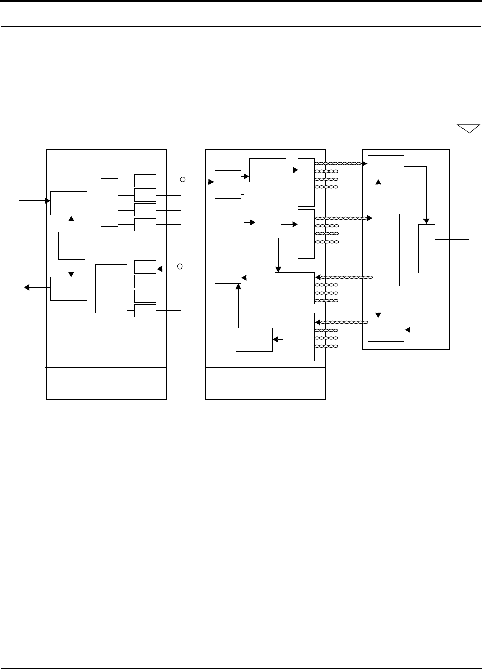
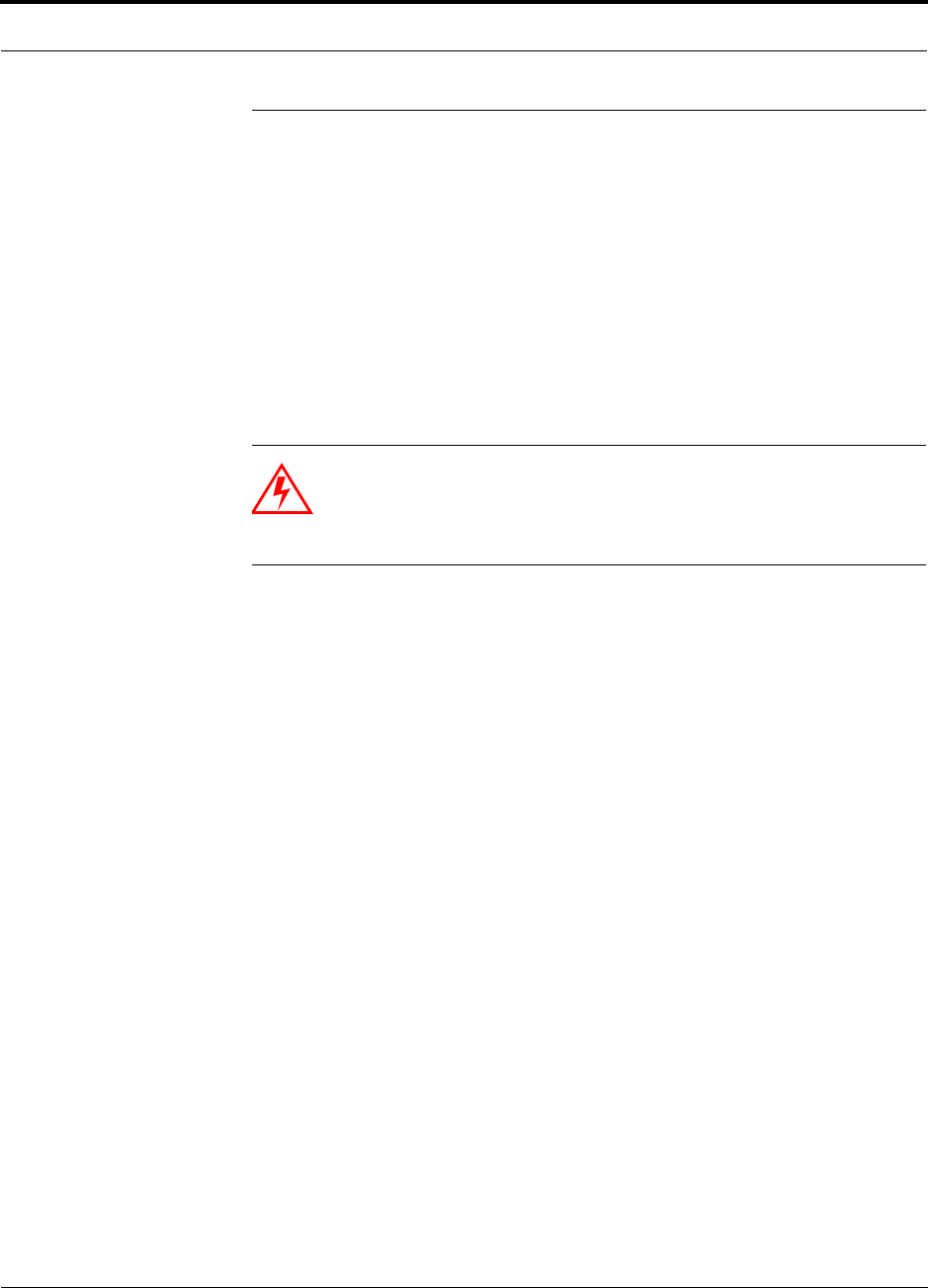
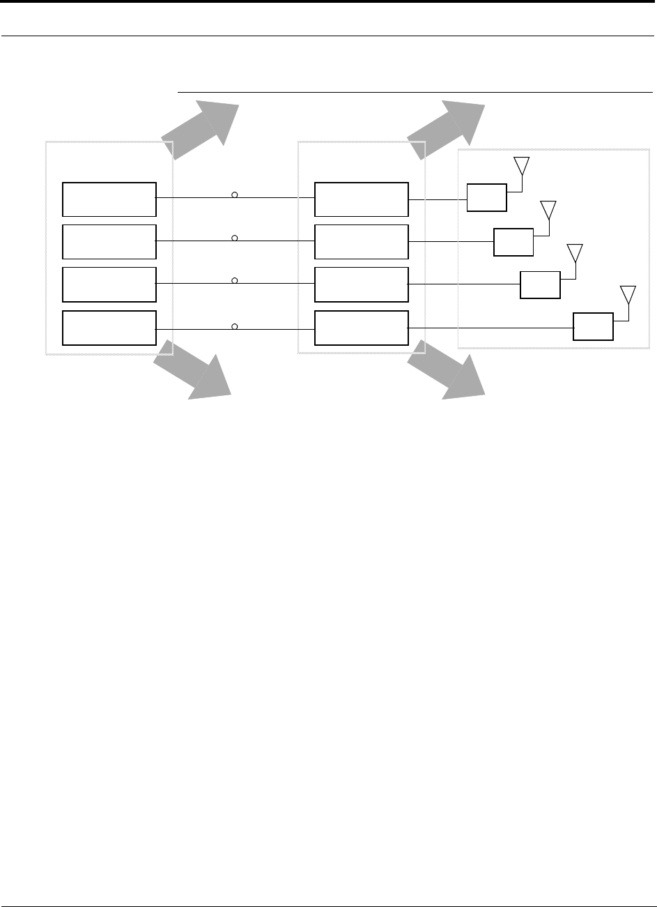
The following figure shows a block diagram of a single band LGCell system. Note
that uplink and downlink RF and control signals for an RAU travel through one Cat-5
cable.
Figure 2-2 LGCell System Block Diagram (Single Band)
RF
Processing
RF
Processing Combiner
Splitter
E/O
E/O
E/O
E/O
E/O
E/O
E/O
E/O
RF
Processing
RF
Processing
Duplexer
O/E
Alarm Control
Power Supply Power Supply EH/RAU
Control
SplitterSplitter
Diagnostics
RF
Processing
Remote Access UnitExpansion HubMain Hub
BTS
or
Repeater
O/E
RF
Processing
Control
Combiner
Control
From/To
Multimode
Fiber
Multimode
Fiber
Cat-5
Cat-5
Cat-5
Cat-5

LGCell 4.0 System Description
2-4 LGCell 4.0 Installation, Operation, and Reference Manual PN 8100-40
620004-0 Rev. E
LGCell components are available in the following frequencies and protocols:
• Single-Band Frequencies and Protocols
• 800 MHz Cellular
• 800 MHz iDEN
• 900 MHz GSM1
• 900 MHz EGSM1
• 1900 MHz PCS (4 band options)
• Dual-Band Frequencies and Protocols
The Main Hubs and Expansion Hubs in a dual-band system each consist of two
single-band hubs. The Dual Band RAUs contain electronics for two bands and
have combined output ports.
• 800 MHz CDMA & 900 MHz GSM (China only)
• 800 MHz Cellular & 1900 MHz PCS
• 900 MHz GSM & 1800 MHz DCS
• 900 MHz EGSM & 1800 MHz DCS
• 1800 MHz DCS & 1800 MHz DCS
1. Approved for use with paging and two-way messaging in the U.S. and Canada.
PN 8100-40 Help Hot Line (U.S. only): 1-800-530-9960 2-5
620004-0 Rev. E
System Operation
2.2 System Operation
Downlink (Base Station/Repeater to Wireless Handsets)
• The LGCell system’s Main Hub is usually installed in a 19 in. (483 mm) equip-
ment rack in a wiring closet or equipment room inside the facility where coverage
will be provided. Coaxial cable is used to connect the Main Hub to a local base sta-
tion or to a repeater that is attached to a roof-top antenna. The Main Hub receives
the incoming RF signals and splits them to feed four internal fiber optic transceiv-
ers that convert the RF signals to optical signals. The Main Hub transmits the opti-
cal signals over multimode fiber to up to four Expansion Hubs, which are usually
installed in other telecom closets throughout the facility.
WARNING: Exceeding the maximum input power could cause failure
of the Main Hub (refer to Section 7.1 on page 7-3 for maximum power
ratings). Attenuators may be required to limit the maximum composite
power into the Main Hub.
•The Expansion Hub converts the optical signals back to electrical signals, which
are then transmitted to up to four Remote Access Units (RAUs) over Cat-5
UTP/STP cabling.
•The Remote Access Unit receives the electrical signals from the Expansion Hub
and transports the signals over a short coaxial cable to an attached passive antenna,
which then transmits the RF signals to wireless handsets.
Uplink (Wireless Handsets to Base Station)
• The passive antenna relays the RF signals from wireless handsets to the Remote
Access Unit, which then transmits the signals to the Expansion Hub over Cat-5
UTP/STP cabling.
•The Expansion Hub converts the electrical signals to optical signals and transmits
the signals to the Main Hub over MMF.
•The Main Hub converts the optical signals to the proper frequency band RF sig-
nals and sends them to a local base station or to a repeater that is connected to a
roof-top antenna.
LGCell 4.0 System Description
2-6 LGCell 4.0 Installation, Operation, and Reference Manual PN 8100-40
620004-0 Rev. E
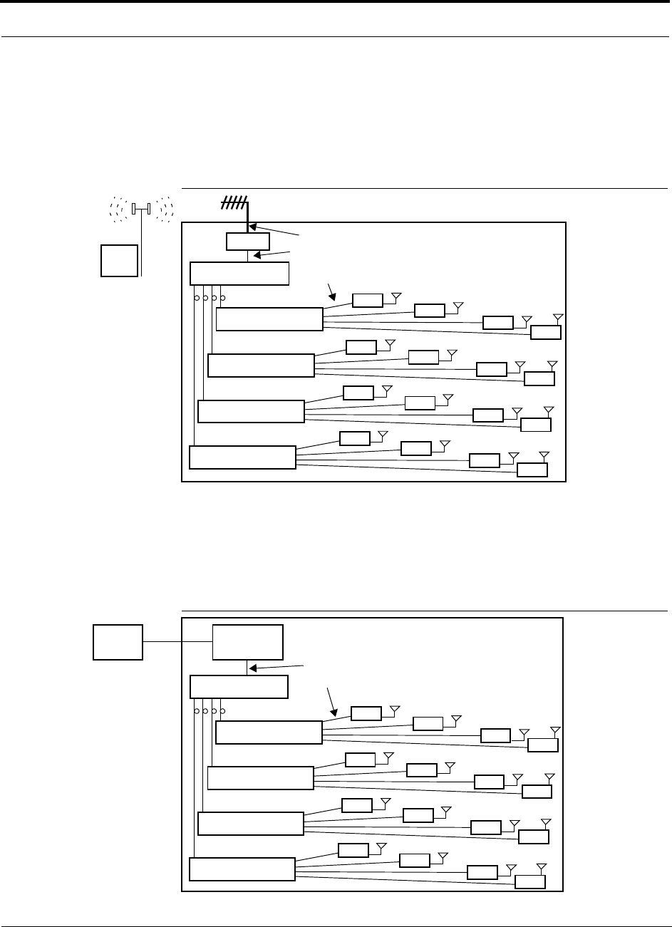
2.2.1 Using LGCell to Increase Coverage and Capacity
You can extend the outdoor, macrocellular network indoors by connecting the
LGCell system to a repeater that is attached to a roof-top antenna. The following fig-
ure illustrates how the LGCell can be used to enhance in-building coverage.
Figure 2-3 Increasing Coverage with LGCell
You can increase the number of users who are able to communicate through their
wireless handheld devices by connecting an LGCell system to a local, centralized
base station. In this configuration, the base station provides voice channel capacity
and the LGCell provides coverage.
Figure 2-4 Increasing Capacity and Coverage with LGCell
In-Building Installation
RAU
RAU
RAU
RAU
RAU
RAU
RAU
RAU
RAU
RAU
RAU
RAU
RAU
RAU
RAU
RAU
LGCell Expansion Hub
LGCell Expansion Hub
LGCell Expansion Hub
LGCell Expansion Hub
Multimode Fiber
Category 5 UTP/STP Cable
for Increased Coverage
LGCell Main Hub
Coaxial Cable
BTS
Roof-top Antenna
Repeater
In-Building Installation
RAU
RAU
RAU
RAU
RAU
RAU
RAU
RAU
RAU
RAU
RAU
RAU
RAU
RAU
RAU
RAU
LGCell Expansion Hub
LGCell Expansion Hub
LGCell Expansion Hub
LGCell Expansion Hub
Multimode Fiber
Category 5 UTP/STP Cable
for Increased Capacity
LGCell Main Hub
Microcellular
Base
Station
Coaxial Cable
Mobile
Switching
Center
T1/E1
and Coverage
PN 8100-40 Help Hot Line (U.S. only): 1-800-530-9960 2-7
620004-0 Rev. E
System Operation
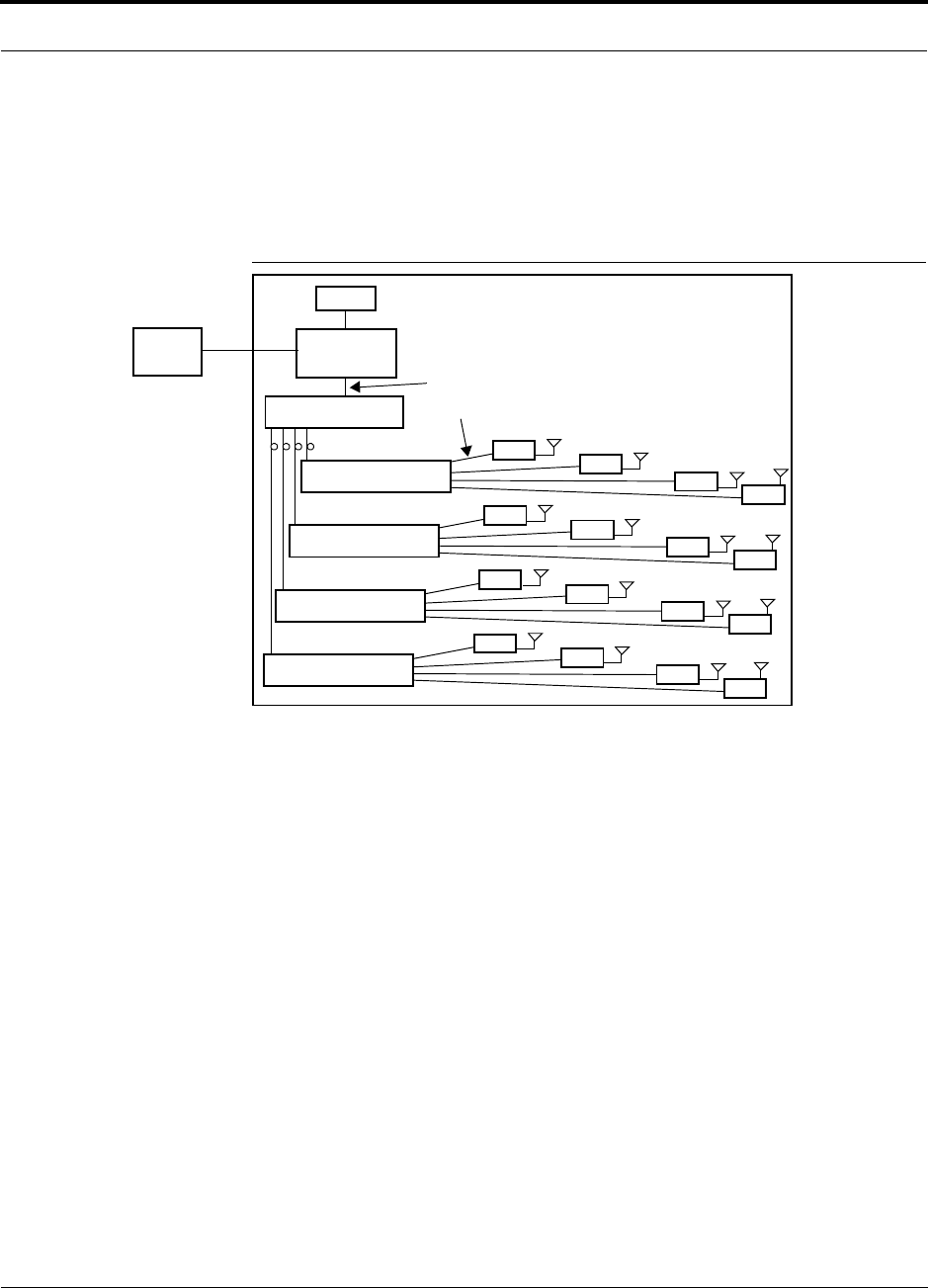
2.2.2 Using LGCell to Increase Coverage, Capacity, and Functionality
Interfacing the LGCell with a base station/PBX network gives wireless phone users
PBX functionality through their wireless phones, anytime, anywhere. The following
figure shows an example installation for wireless office service (WOS).
Figure 2-5 Increasing Coverage, Capacity, and Functionality with LGCell
With the LGCell/base station/PBX* solution, employees can use a wireless phone in
place of a wireline desk phone to access the PBX while inside the building and use
the same phone for wireless communications while outside the building. Employees
can access PBX features such as four-digit dialing, call delivery, call forwarding,
call-waiting, conferencing, and voice mail from their wireless phone.
In this configuration, the base station private wireless network transmits RF signals
indoors, and the macrocellular network takes over outdoors.
*Check with your PBX manufacturer/vendor for compatibility, connection, and oper-
ation.
In-Building Installation
for Increased Coverage,
Microcellular
Base
Station
PBX
Capacity, and
Functionality
RAU
RAU
RAU
RAU
RAU
RAU
RAU
RAU
RAU
RAU
RAU
RAU
RAU
RAU
RAU
RAU
LGCell Expansion Hub
LGCell Expansion Hub
LGCell Expansion Hub
LGCell Expansion Hub
Multimode Fiber
Category 5 UTP/STP Cable
LGCell Main Hub
Coaxial Cable
Mobile
Switching
Center
T1/E1

LGCell 4.0 System Description
2-8 LGCell 4.0 Installation, Operation, and Reference Manual PN 8100-40
620004-0 Rev. E
2.2.3 Using LGCell to Simultaneously Support Multiple
Bands/Protocols
The LGCell can simultaneously support more than one frequency band. Two options
include:
• The Dual Band LGCell for an Operator running parallel networks in the same mar-
ket
• The neutral host configuration, which is described here
The term “neutral host” refers to the fact that the system supports multiple wireless
Operators and that the equipment typically is owned by a third-party company.
Neutral host systems are deployed in situations such as the following:
• Public microcellular applications such as airport terminals, subways/train stations,
and similar public buildings usually require that the in-building RF distribution
system infrastructure be capable of supporting any current frequency band and
protocol, including paging and messaging, and that it be future-proof.
• It is common for the same service provider to be licensed to operate in multiple
bands in the same geographical area. For example, some Asian and European ser-
vice providers have licenses in both 900 MHz and 1800 MHz bands. Some North
American service providers operate in both 800 MHz and 1900 MHz bands.
• A building owner will often allow service providers to provide wireless service in
their building only if they cooperate and share the infrastructure equipment and
distribution system. Delays in service implementation and loss of revenue occur
when the competing service providers do not agree on how to share the equipment
and installation costs.
Additional distribution cabling infrastructure, beyond initial requirements, often is
installed to accommodate adding Operators or services or to enhance capacity by sec-
torizing the distribution equipment at a later time.
PN 8100-40 Help Hot Line (U.S. only): 1-800-530-9960 2-9
620004-0 Rev. E
System Operation
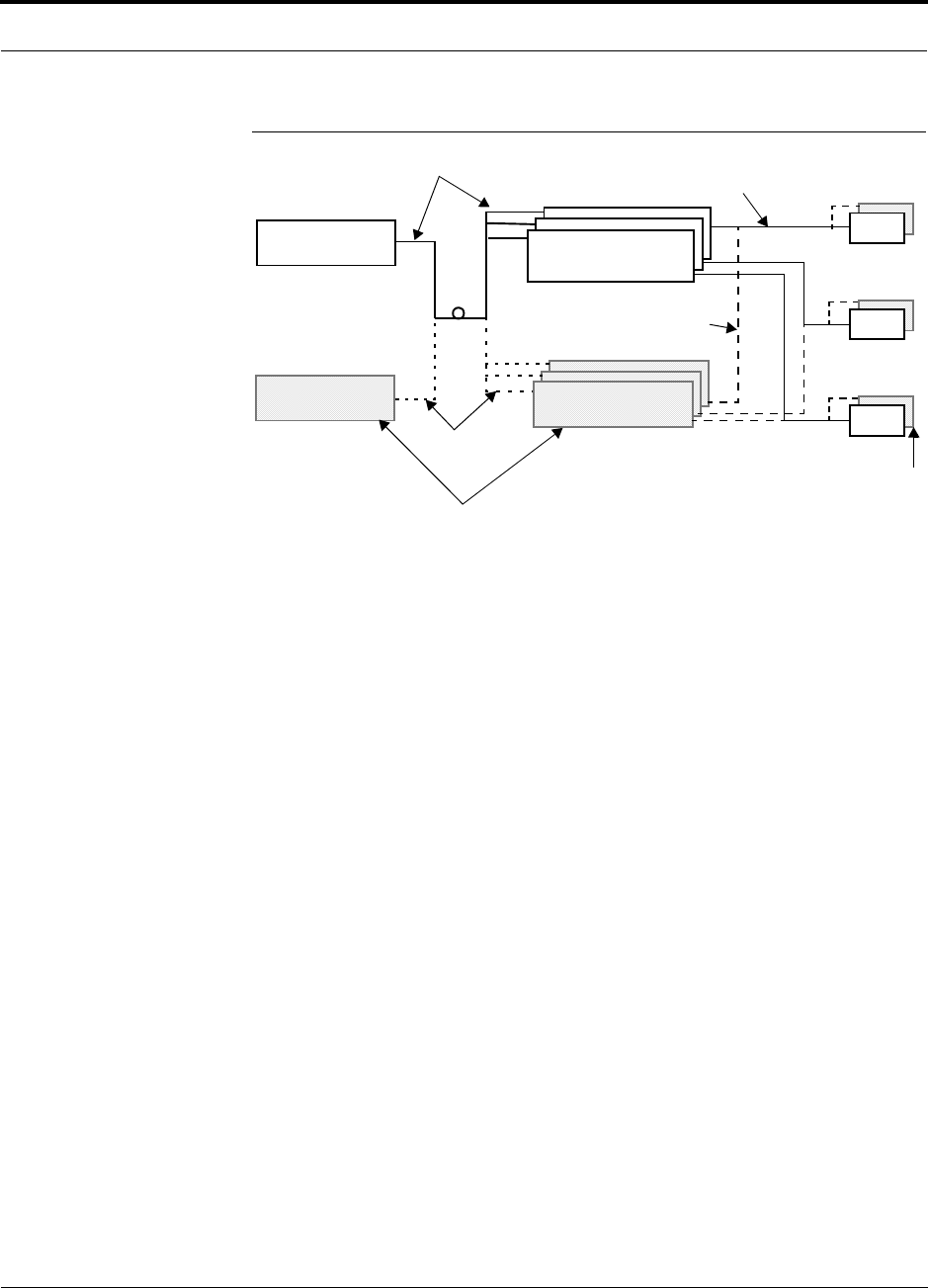
Figure 2-6 Example Neutral Host Application
Neutral host systems are deployed as shared or dedicated systems.
•Shared System: Multiple wireless Operators use the same set of LGCell hard-
ware to distribute RF signals.
•Dedicated System: Each Operator uses an independent LGCell system.
In order to simplify coverage planning and minimize installation costs, the equipment
is “clustered” and installed in groups. The number of Hubs and RAUs required for a
system is determined by their ability to be shared.
The configuration shown in Figure 2-7 supports up to 7 Operator bands.
LGCell Main Hub
Operator 1
RAU
Cat-5 Cable:
RAU
RAU
LGCell Expansion Hub
Op. 1 and/or Op. 2
LGCell Main Hub
Op. 1 and/or Op. 2
Installed now,
used now
Cat-5 Cable:
Installed now,
used later
Fiber Optic Cable:
Installed now,
used later
Fiber Optic Cable:
Installed now,
used now
Future LGCell Equipment
Future LGCell Equipment
LGCell Expansion Hub
Operator 1
(Operator 2 in the future)
LGCell 4.0 System Description
2-10 LGCell 4.0 Installation, Operation, and Reference Manual PN 8100-40
620004-0 Rev. E
Figure 2-7 LGCell Neutral Host Configuration
Refer to the Neutral Host Planning Guide (PN 9000-10) for more information about
this type of configuration.
RAU
Clusters B and C
Expansion Hub
Cluster 4
RAU
Clusters D
iDEN
Main Hub Cat-5
Optical Fiber
800 MHz iDEN
Main Hub
800 MHz A and B
Main Hub
1900 MHz A and D
Main Hub
1900 MHz B and E
Main Hub Cluster
Expansion Hub
800 MHz iDEN
Expansion Hub
800 MHz A and B
Expansion Hub
1900 MHz A and D
Expansion Hub
1900 MHz B and E
Expansion Hub
Cluster 1
RAU
A/D
RAU
B/E
RAU
A/B
RAU
Expansion Hub
Clusters 2 and 3
RAU
Cluster A
PN 8100-40 Help Hot Line (U.S. only): 1-800-530-9960 2-11
620004-0 Rev. E
System Bandwidths
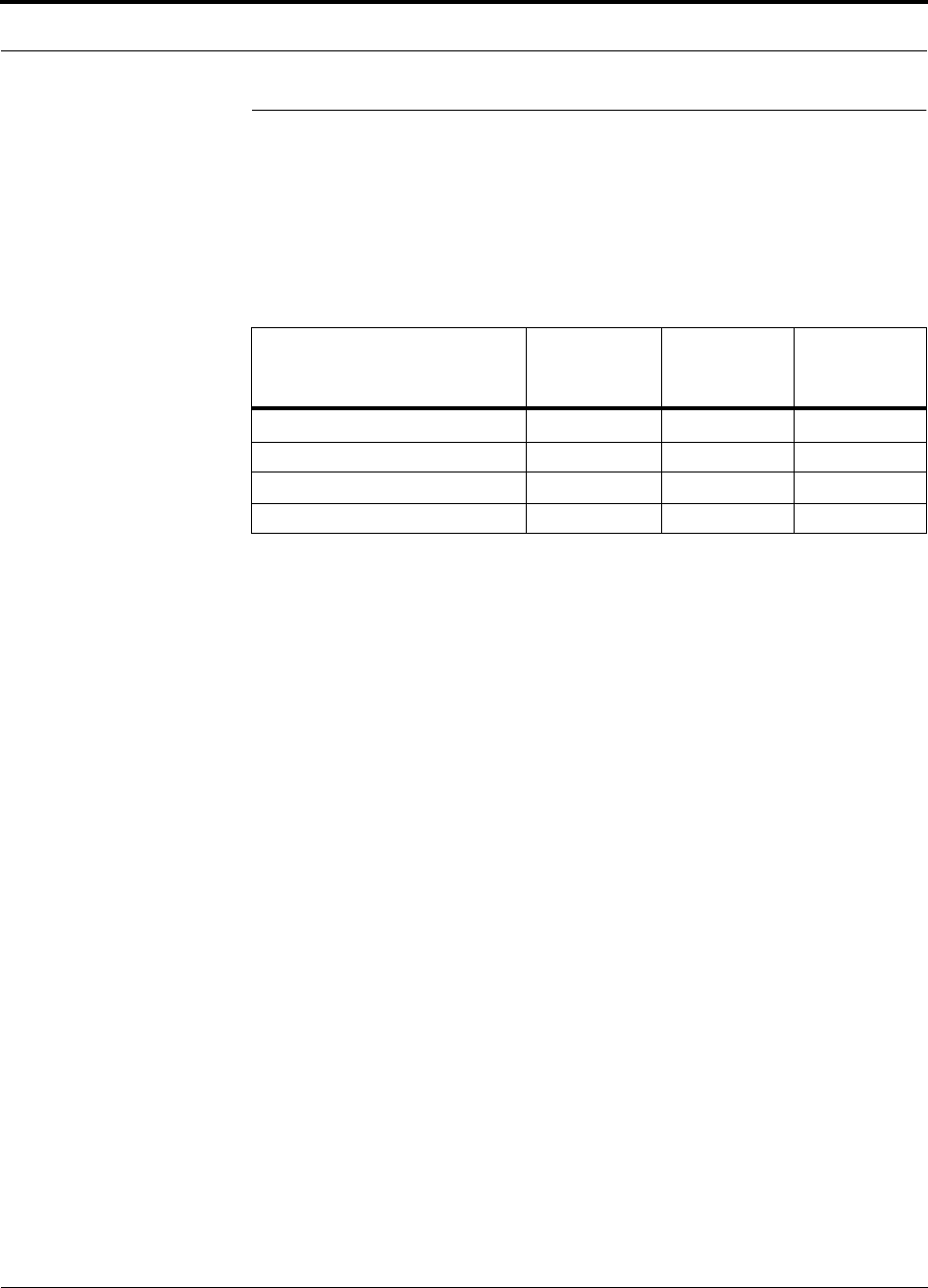
2.3 System Bandwidths
2.3.1 800 MHz and 900 MHz Systems
The 800 MHz and 900 MHz LGCell systems have fixed bandwidths of operation, as
shown in the following table.
Table 2-1 Bandwidths: 800 and 900 MHz
LGCell System
System
Bandwidth
(MHz)
Uplink
Freq. Range
(MHz)
Downlink
Freq. Range
(MHz)
800 MHz Cellulara
a. The 800 MHz CDMA/900 MHz GSM dual-band LGCell is composed of two single-band LGCells
(one 800 MHz Cellular and one 900 MHz GSM) and supports the following frequency bands:
800 MHz CDMA
Downlink: 870 to 880 MHz
Uplink: 825 to 835 MHz
Bandwidth: 10 MHz
900 MHz GSM:
Downlink: 954 to 960 MHz
Uplink: 909 to 915 MHz
Bandwidth: 6 MHz
25 824–849 869–894
800 MHz iDEN 18 806–824 851–869
900 MHz GSMa25 890–915 935–960
900 MHz EGSM 35 880–915 925–960
LGCell 4.0 System Description
2-12 LGCell 4.0 Installation, Operation, and Reference Manual PN 8100-40
620004-0 Rev. E
2.3.2 1800 MHz and 1900 MHz Systems
The 1800 MHz DCS (GSM) and 1900 MHz PCS systems have a bandpass filter that
is positioned within the uplink and downlink bands. This position is specified when
the equipment is ordered and it is set during manufacturing.
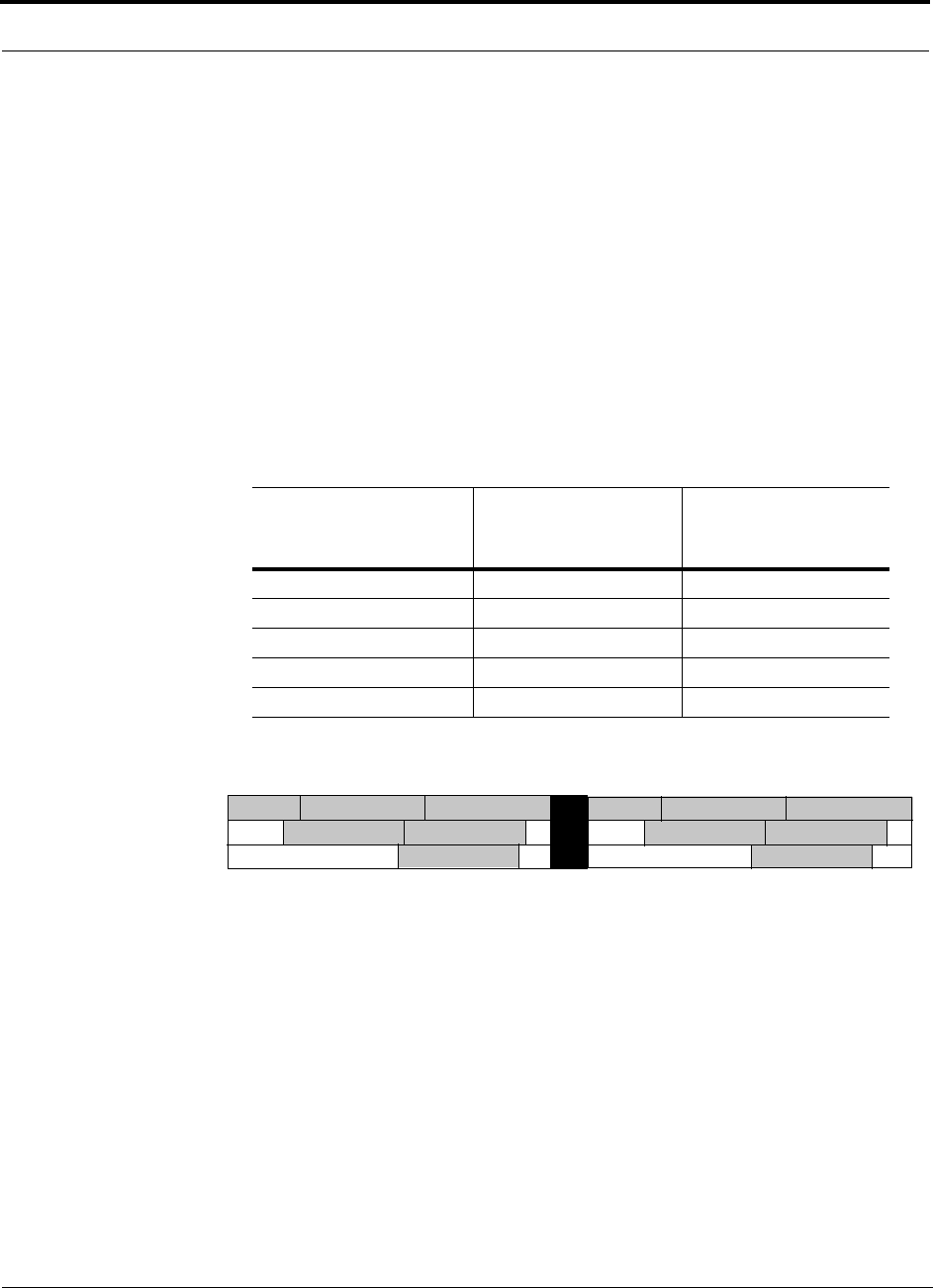
1800 MHz DCS (GSM) System Bandwidth
The 1800 MHz DCS (GSM) bandpass filter is positioned within the 75 MHz band
during manufacturing. The bandpass filter is 30 MHz for all bands except DCS1,
which is 15 MHz.
When ordering the DCS product, select the appropriate band of operation from the
list of available bands as shown in the following table.
Table 2-2 Band Frequency of the DCS 1800 MHz LGCell
Band
System
Bandwidth
(MHz) Uplink (MHz) Downlink (MHz)
DCS 1 15 1710 to 1725 1805 to 1820
DCS 2 30 1725 to 1755 1820 to 1850
DCS 3 30 1755 to 1785 1850 to 1880
DCS 4 30 1721.25 to 1751.25 1816.25 to 1846.25
DCS 5 30 1751.25 to 1781.25 1846.25 to 1876.25
DCS 6
DCS 1 DCS 2 DCS 3
DCS 4 DCS 5
DCS Uplink Bands
1710 1725 1755
1721.25 1751.25 1781.25
1785
DCS Downlink Bands
1805 1820 1850
1816.25 1846.25 1876.25
1880
DCS 1 DCS 2 DCS 3
DCS 4 DCS 5
DCS 6
1750 1780 1840 1870
PN 8100-40 Help Hot Line (U.S. only): 1-800-530-9960 2-13
620004-0 Rev. E
System Bandwidths
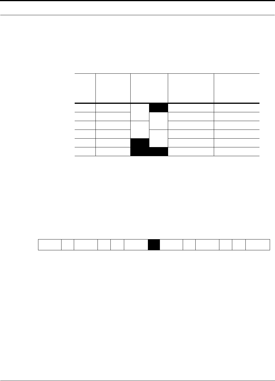
1900 MHz PCS System Bandwidth
The 1900 MHz PCS bandpass filter is positioned within the 60 MHz band during
manufacturing. The PCS bandpass filter is 20 MHz.
LGCell equipment can be ordered in the following configurations:
• Bands A and D
• Bands D and B
• Bands B and E
• Bands E and F
LGCell equipment does not support band C.
Table 2-3 Bandwidths: 1900 MHz PCS
Band
PCS
Bandwidth
in the US
(MHz)
LGCell
System
Bandwidth
(MHz)
Uplink
(MHz)
Downlink
(MHz)
A15 20 1850 to 1865 1930 to 1945
D5 20 1865 to 1870 1945 to 1950
B15 20 1870 to 1885 1950 to 1965
E5 10 1885 to 1890 1965 to 1970
F5 1890 to 1895 1970 to 1975
C15 1895 to 1910 1975 to 1990
ADBEF C
PCS Uplink Bands
1850 1865 1870 1885 1890 1895 1910
ADBEF C
PCS Downlink Bands
1930 1945 1950 1965 1970 1975 1990

LGCell 4.0 System Description
2-14 LGCell 4.0 Installation, Operation, and Reference Manual PN 8100-40
620004-0 Rev. E
2.4 System Specifications
2.4.1 Physical Specifications
Parameter Main Hub Expansion Hub Remote Access Unit
RF Connectors 3, N-type female 4, RJ-45 Single Band: 1, RJ-45;
1, SMA female
Dual Band (900/1800,
800/900, 800/1900):
2, RJ-45; 1, SMA female
Dual Band (1800/1800):
2, RJ-45; 2, SMA female
Remote Alarm
Connector
(contact closure)
1, 9-pin D-sub, female
1, 25-pin D-sub (not used),
male
——
MMF Connectors 4 Pair, ST female 1 Pair, ST female —
LED Alarm and
Status Indicators
Sync, Power, Port Link Status,
Port Sync
Sync, Power, Port Link Status,
Port Sync
Power, Sync
AC Power (Universal)
Typical
Maximum
117V AC, 0.22 amp @ 60 Hz
230V AC, 0.11 amp @ 50 Hz
117V AC, 0.30 amp @ 60 Hz
230V AC, 0.15 amp @ 50 Hz
117V AC, 0.47 amp @ 60 Hz
230V AC, 0.24 amp @ 50 Hz
117V AC, 0.64 amp @ 60 Hz
230V AC, 0.32 amp @ 50 Hz
—
—
Power Consumption
Typical
Maximum
25 W
35 W
32 W / 55 W with 4 RAUs
45 W / 75 W with 4 RAUs
5.7 W
7.5 W
Enclosure Dimensions
(height × width × depth)
Excluding angle-brack-
ets for 19'' rack mount-
ing of hubs.
44.5 mm × 438 mm × 229 mm
(1.75 in. × 17.25 in. × 9 in.)
1U
44.5 mm × 438 mm × 229 mm
(1.75 in. × 17.25 in. × 9 in.)
1U
Single Band:
36 mm × 110 mm × 140 mm
(1.4 in. × 4.3 in. × 5.5 in.)
Dual Band (900/1800,
1800/1800):
68 mm × 157 mm × 203 mm
(2.7 in. × 6.2 in. × 8 in.)
Dual Band (800/900,
800/1900):
35 mm × 261 mm × 200 mm
(1.4 in. × 10.3 in. × 7.9 in.)
Weight < 3 kg (< 6.5 lb) < 3 kg (< 6.5 lb) Single Band:
< 0.4 kg (<1 lb)
Dual Band:
< 0.8 kg (< 1.8 lb)
MTBF (hours) 298,000 461,000 965,000
PN 8100-40 Help Hot Line (U.S. only): 1-800-530-9960 2-15
620004-0 Rev. E
System Specifications
2.4.2 Environmental Specifications
2.4.3 Alarm LEDs
The Main Hub has LINK STATUS and SYNC LEDs for each fiber port. The Expansion
Hub has LINK STATUS and SYNC LEDs for each Cat-5 (RAU) port.
Parameter Rating
Operating Temperature 0° to +45°C / 32° to +113°F
Non-operating Temperature –20° to +85°C / –4° to +185°F
Operating Humidity; non-condensing 5% to 95%
Unit Alarm Name LED Color Condition
Main Hub Power Green AC power is ON
Sync
(above power)
Green Main Hub’s phase lock loop (PLL) is locked
Off Main Hub’s PLL is not locked
Port Link Status Green The Main Hub is receiving a signal from the Expansion Hub without
an alarm signal
Red The Main Hub is receiving an alarm signal from the Expansion Hub
Port Sync Green The Expansion Hub and its connected RAUs do not have an alarm
Red There is no Expansion Hub connected
Expansion Hub Power Green AC power is ON
Sync
(above power)
Green The Expansion Hub is receiving the pilot signal
Off The Expansion Hub is not receiving the pilot signal
Port Link
Status/Port
Sync
Green/Green The RAU is connected and functioning properly
Green/Red The Connected RAU is malfunctioning
Red/Green The RAU has been disconnected or the cable is cut
Red/Red No RAU is connected
RAU Power Green DC power to RAU
Sync Red PLL is not locked or clock power is low

LGCell 4.0 System Description
2-16 LGCell 4.0 Installation, Operation, and Reference Manual PN 8100-40
620004-0 Rev. E
PN 8100-40 LGCell 4.0 Installation, Operation, and Reference Manual 3-1
620004-0 Rev. E
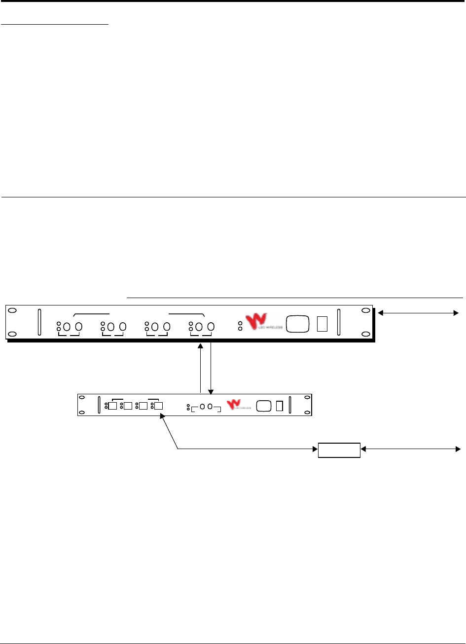
SECTION 3 LGCell Main Hub
The Main Hub is the LGCell’s central distribution point. On the dowlink, it receives
RF signals from a base station or a repeater and converts them to optical signals,
which it distributes to Expansion Hubs. On the uplink, the Main Hub receives optical
signals from the Expansion Hubs and converts them back to RF signals to be relayed
to a base station or a repeater.
Figure 3-1 The Main Hub in an LGCell 1-1-1 Configuration*
LGCell Main Hub Features
• Mounts in a standard 19 in. (483 mm) equipment rack
• Connects to a base station or repeater using coaxial cable
• Supports up to four Expansion Hubs using standard 62.5µm/125µm multimode
fiber (MMF) cable
• Displays system status with front panel LEDs
• Provides contact closures and error latches for major errors through a D-sub
9-pin connector on the rear panel
RAU
Multimode Fiber
between Main Hub
and Expansion Hub
Cat-5 UTP/STP
between Expansion Hub and RAU
Main Hub and
Base Station or
Coaxial Cable between
Coaxial Cable between
AC POWER
LGCell
TM
Main Hub
SYNC
POWER
LINK
SYNC
STATUS
DOWN UP
1
LINK
SYNC
STATUS
DOWN UP
2
LINK
SYNC
STATUS
DOWN UP
3
LINK
SYNC
STATUS
DOWN UP
4
TO EXPANSION HUB PORTS
AC POWER
LGCell
TM
Expansion Hub
SYNC
POWER
SYNC
LINK
STATUS
ANTENNA PORTS
DOWN UP
MAIN HUB PORT
Repeater
RAU and Passive Antenna
*1-1-1 configuration = 1 Main Hub, 1 Expansion Hub, and 1 Remote Access Unit
LGCell Main Hub
3-2 LGCell 4.0 Installation, Operation, and Reference Manual PN 8100-40
620004-0 Rev. E
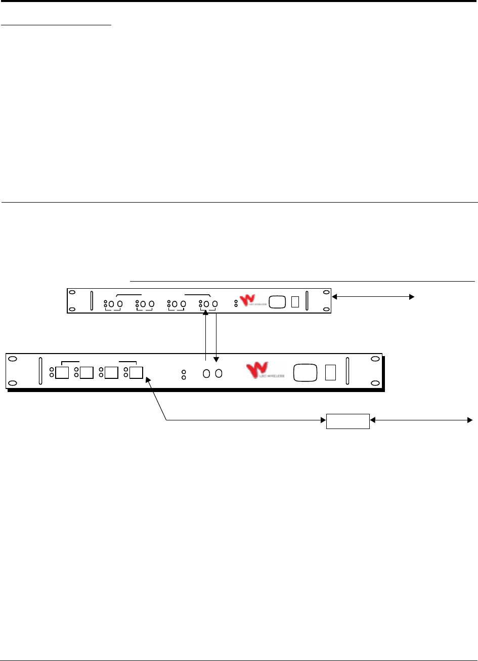
3.1 LGCell Main Hub Front Panel
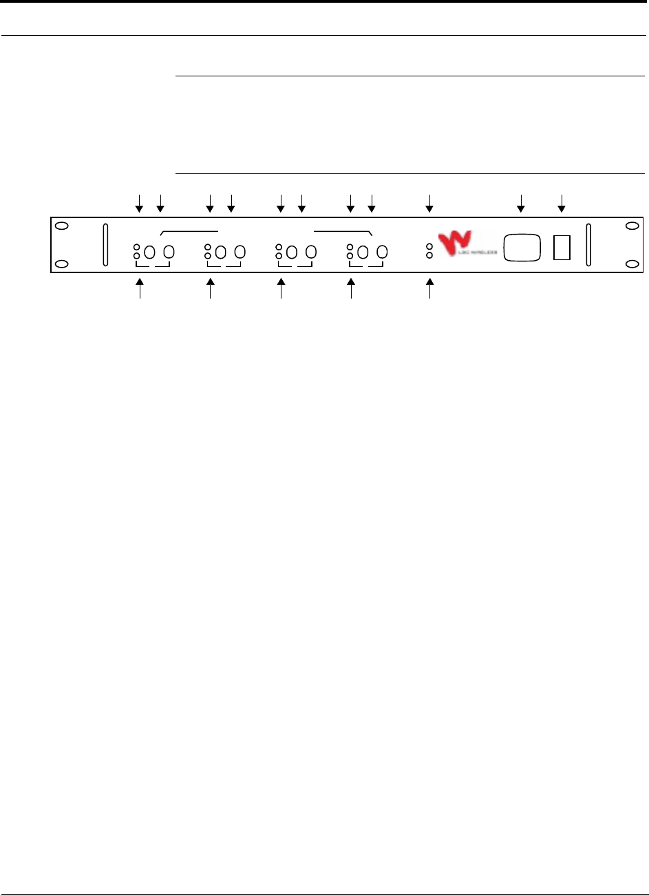
The front panel of a Main Hub is shown in the following figure.
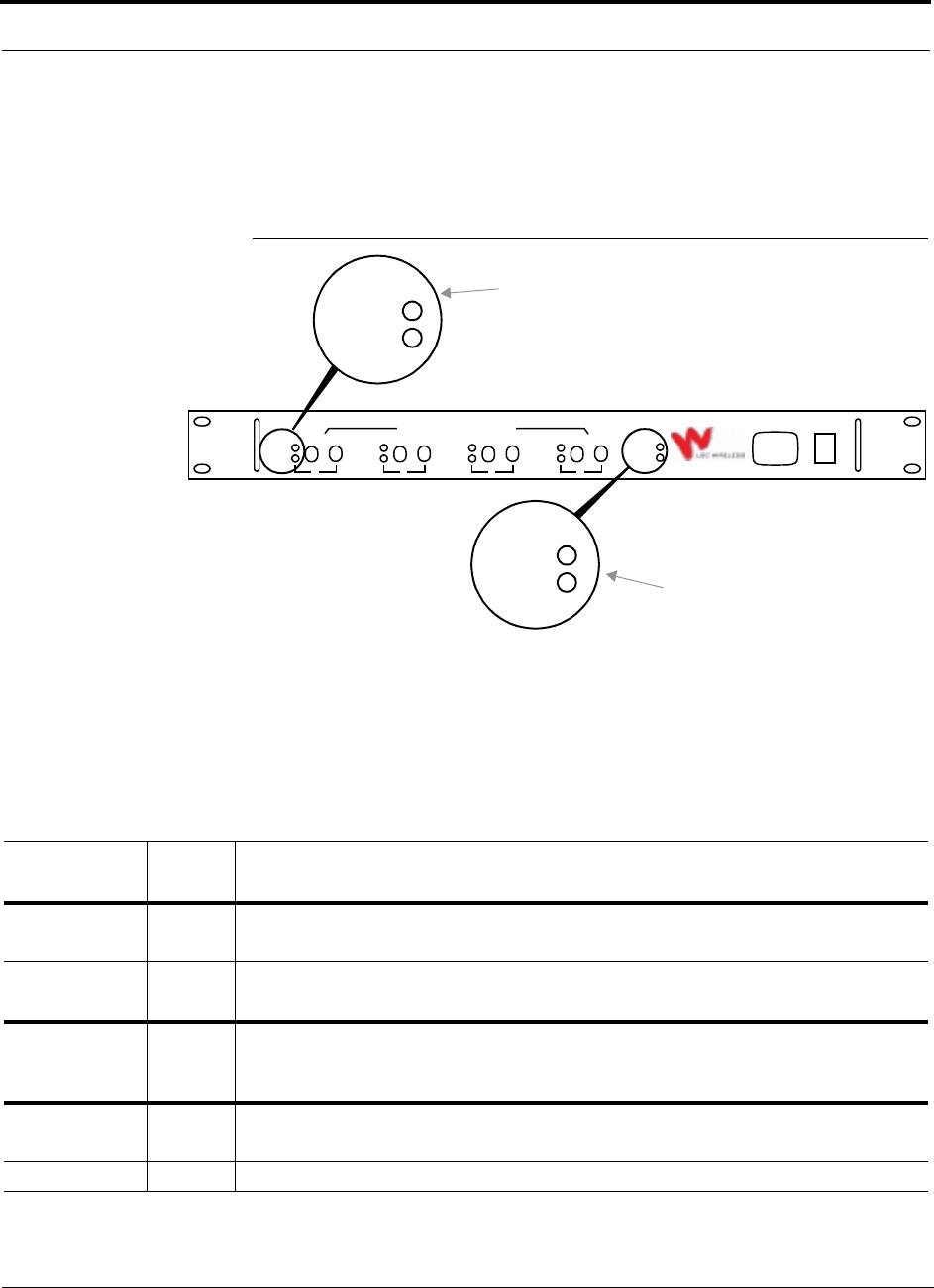
Figure 3-2 Front Panel of a Main Hub
1. AC power cord connector
2. Power On/Off switch
3. One LED for unit sync status (labeled SYNC)
4. One LED for unit power status (labeled POWER)
5. Four MMF ports (labeled 1, 2, 3, 4)
• One standard female ST optical connector for MMF downlink (labeled DOWN)
• One standard female ST optical connector for MMF uplink (labeled UP)
6. One LED per port for port link status (labeled LINK STATUS)
7. One LED per port for port sync status (labeled SYNC)
123
4
56
7
AC POWER
LGCell
TM
Main Hub
SYNC
POWER
LINK
SYNC
STATUS
DOWN UP
1
LINK
SYNC
STATUS
DOWN UP
2
LINK
SYNC
STATUS
DOWN UP
3
LINK
SYNC
STATUS
DOWN UP
4
TO EXPANSION HUB PORTS
56
7
56
7
56
7
PN 8100-40 Help Hot Line (U.S. only): 1-800-530-9960 3-3
620004-0 Rev. E
LGCell Main Hub Front Panel
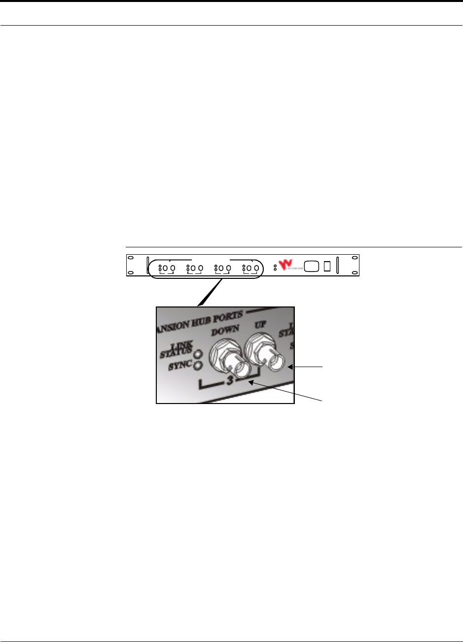
3.1.1 MMF Downlink/Uplink Ports
The Main Hub’s MMF downlink/uplink ports transmit/receive optical signals to/from
Expansion Hub(s) using industry-standard 62.5µm/125µm MMF cable. There are
four MMF ports (labeled 1, 2, 3, and 4) on the Main Hub’s front panel. Each MMF
port has two female ST optical connectors: one for downlink (output) and one for
uplink (input).
• MMF Downlink Connector
This female ST connector (labeled DOWN) is used to transmit the downlink optical
signals to an attached Expansion Hub.
• MMF Uplink Connector
This female ST connector (labeled UP) is used to receive the uplink optical signals
from an attached Expansion Hub.
Figure 3-3 MMF Downlink/Uplink Ports on the Main Hub
Port Disconnect Memory
The Main Hub detects when active fiber is connected to its MMF ports. An alarm is
issued and latched if an active fiber cable from an MMF port on the Main Hub or an
attached Expansion Hub is disconnected. The port disconnect memory and major
alarm are cleared if you reconnect the fiber into the same functioning port. The error
latch remains active until power is cycled. If you do not want to use that port, you
should cycle the Main Hub’s power to clear the port disconnect memory and the error
latch.
Uplink/Input from Expansion Hub
Downlink/Output to Expansion Hub
Female ST optical connector
Female ST optical connector
AC POWER
LGCell
TM
Main Hub
SYNC
POWER
LINK
SYNC
STATUS
DOWN UP
1
LINK
SYNC
STATUS
DOWN UP
2
LINK
SYNC
STATUS
DOWN UP
3
LINK
SYNC
STATUS
DOWN UP
4
TO EXPANSION HUB PORTS
LGCell Main Hub
3-4 LGCell 4.0 Installation, Operation, and Reference Manual PN 8100-40
620004-0 Rev. E
3.1.2 Main Hub LED Indicators
The front panel of the Main Hub has LEDs that provide diagnostic information and
operational status of the unit.
Figure 3-4 Main Hub Front Panel LEDs
The Main Hub’s MMF port LEDs can be used to help troubleshoot downstream prob-
lems; however, the LEDs do not indicate which downstream component has the prob-
lem.
The Main Hub’s LED indicators are described in the following table.
Table 3-1 Main Hub LED Indicators
MMF Port
Indicators Color Indicates
LINK STATUS Green
Red
Good connection to the Expansion Hub that is connected to the port.
Connection problem with the Expansion Hub that is connected to the port.
SYNC Green
Red
Expansion Hub connected to the port is operating properly.
An alarm with the Expansion Hub that is connected to the port.
Unit
Functionality
Indicators Color Indicates
SYNC Green
Off
Main Hub is correctly producing the synchronization signal.
Main Hub is not correctly producing the synchronization signal.
POWER Green Main Hub has power.
MMF Port LED Indicators
Unit Functionality LED Indicators
(1 pair per hub)
(1 pair for each MMF port)
AC POWER
LGCell
TM
Main Hub
SYNC
POWER
LINK
SYNC
STATUS
DOWN UP
1
LINK
SYNC
STATUS
DOWN UP
2
LINK
SYNC
STATUS
DOWN UP
3
LINK
SYNC
STATUS
DOWN UP
4
TO EXPANSION HUB PORTS
LINK
STATUS
SYNC
SYNC
POWER
PN 8100-40 Help Hot Line (U.S. only): 1-800-530-9960 3-5
620004-0 Rev. E
LGCell Main Hub Rear Panel
3.2 LGCell Main Hub Rear Panel
The rear panel of a Main Hub is shown in the following figure.
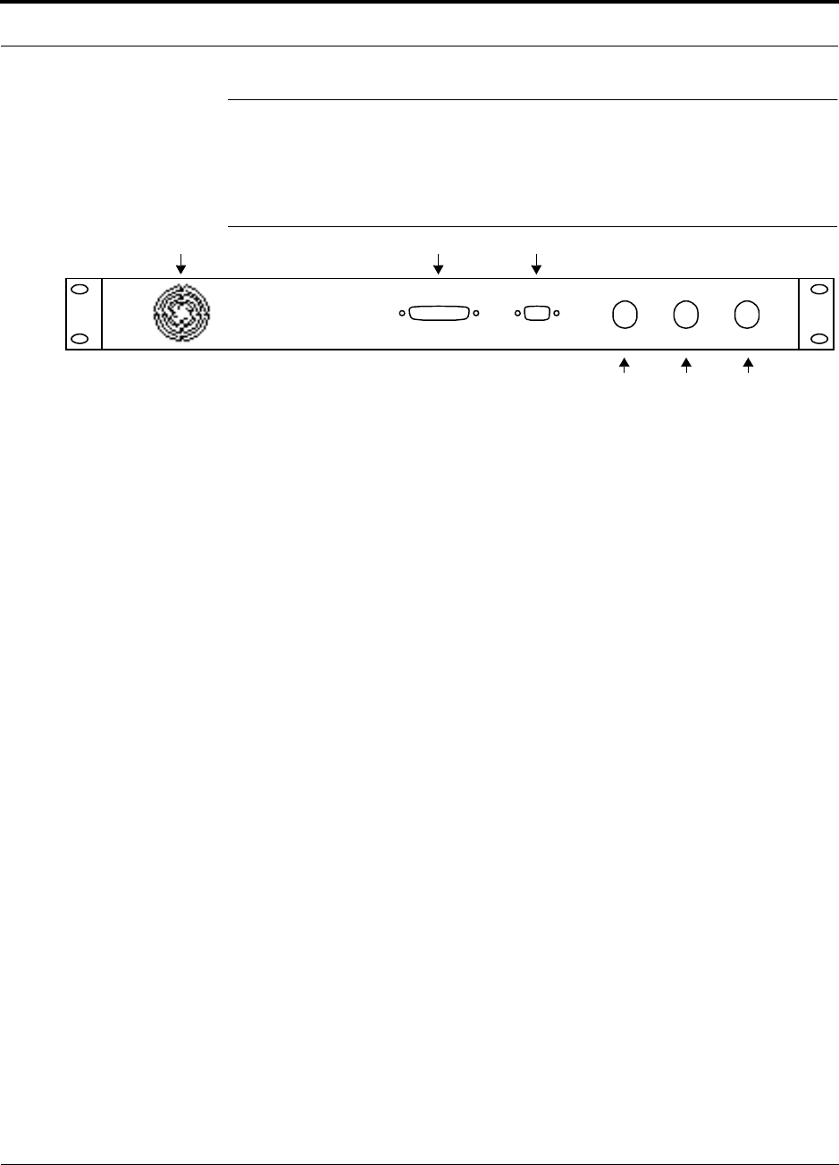
Figure 3-5 Rear Panel of a Main Hub
1. Three N-type, female connectors with dust caps:
• One simplex uplink, unidirectional (labeled REVERSE)
• One simplex downlink, unidirectional (labeled FORWARD)
• One duplexed, bidirectional (labeled DUPLEX)
2. One 9-pin D-sub connector (labeled DIAGNOSTIC 1)
3. One 25-pin D-sub connector, factory use only (labeled DIAGNOSTIC 2)
4. Air exhaust vent
111
4
REVERSE FORWARD DUPLEX
DIAGNOSTIC 2 DIAGNOSTIC 1
3 2
LGCell Main Hub
3-6 LGCell 4.0 Installation, Operation, and Reference Manual PN 8100-40
620004-0 Rev. E
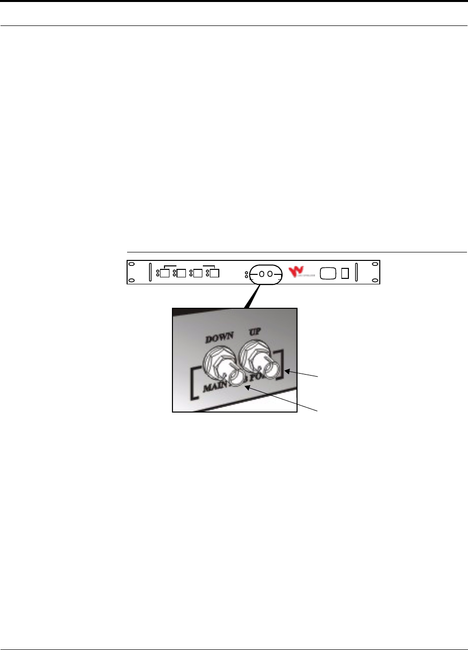
3.2.1 Main Hub Rear Panel Connectors
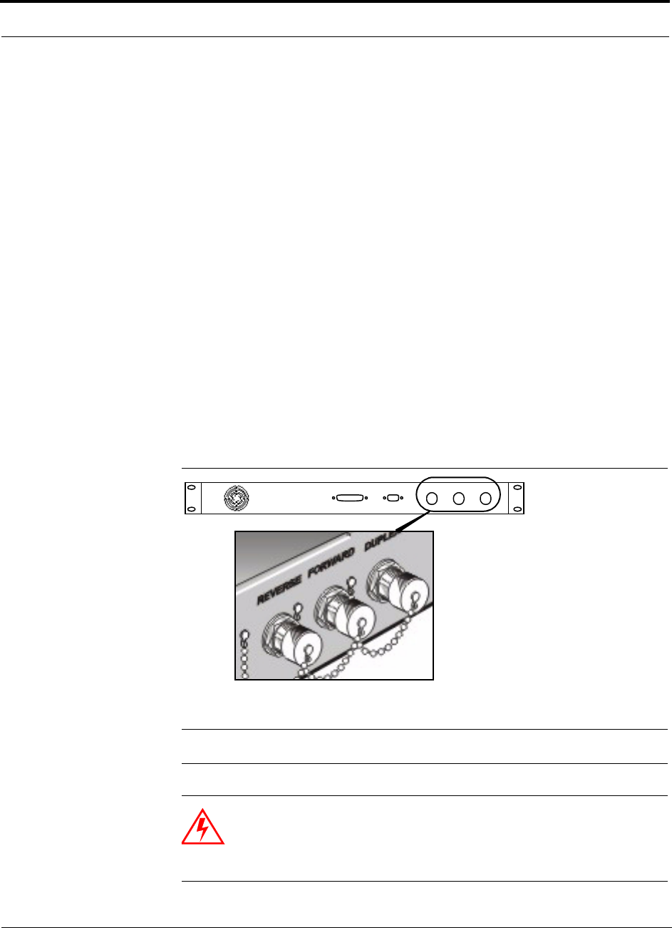
N-Type Female Connectors
There are three N-type female connectors on the rear panel of the Main Hub: one
duplex and two simplex. Generally, the simplex connectors are used together and the
duplex connector is used by itself.
• Simplex Connectors
The simplex connectors provide unidirectional connection of a Main Hub to a
local base station or to a repeater that is connected to a roof-top antenna.
–The
REVERSE connector transmits uplink RF signals to a base station or a
repeater.
–The
FORWARD connector receives downlink RF signals from a base station
or a repeater.
• Duplex Connector
The DUPLEX connector provides bidirectional (both uplink and downlink) con-
nection between the Main Hub and a base station or a repeater. This connector
has a fixed gain of 0, 30, or 40 dB, depending on the system (see Table 7-22 on
page 7-25).
Figure 3-6 N-type Female Connectors on the Main Hub
NOTE: Always keep the dust cap on unused N-type connectors.
WARNING: Exceeding the maximum input power could cause failure
of the Main Hub (refer to Section 7.1 on page 7-3 for maximum power
ratings). Attenuators may be required to limit the maximum composite
power into the Main Hub.
REVERSE FORWAR D DUPLEX
DIAGNOSTIC 2 DIAGNOSTIC 1
PN 8100-40 Help Hot Line (U.S. only): 1-800-530-9960 3-7
620004-0 Rev. E
LGCell Main Hub Rear Panel
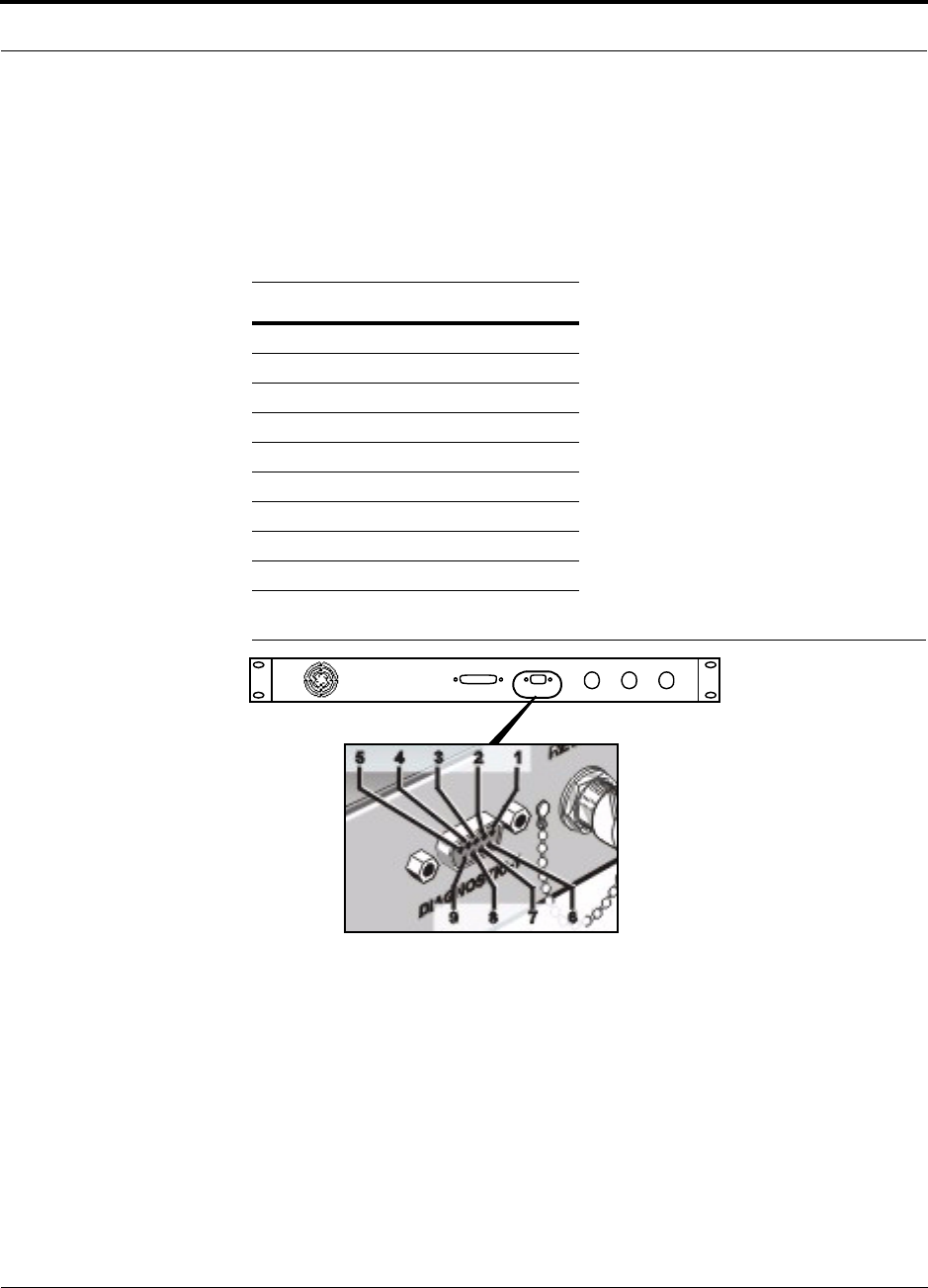
9-pin D-sub Connector
The 9-pin D-sub connector (labeled DIAGNOSTIC 1) provides contact closures and
error latches for monitoring major errors.
The following table lists the function of each pin on the 9-pin D-sub connector. Pin
locations are labeled on Figure 3-7.
Figure 3-7 9-pin D-sub Connector on the Main Hub
Use the error pin connections to determine the error status: send a current of no more
than 40 mA @ 40V DC maximum (4 mA @ 12V DC typical) through the positive
connection. The current will return through the negative connection. An error is indi-
cated if current ceases to flow through the error connection.
25-pin D-sub Connector
Reserved for factory use only.
Pin Function
1 +10 V (fused)
2 Not connected
3 Not connected
4 Error Latch (positive connection)
5 Error Latch (negative connection)
6 DC Ground (common)
7 Major Error (positive connection)
8 Error Reset
9 Major Error (negative connection)
REVERSE FORWARD DUPLEX
DIAGNOSTIC 2 DIAGNOSTIC 1
LGCell Main Hub
3-8 LGCell 4.0 Installation, Operation, and Reference Manual PN 8100-40
620004-0 Rev. E
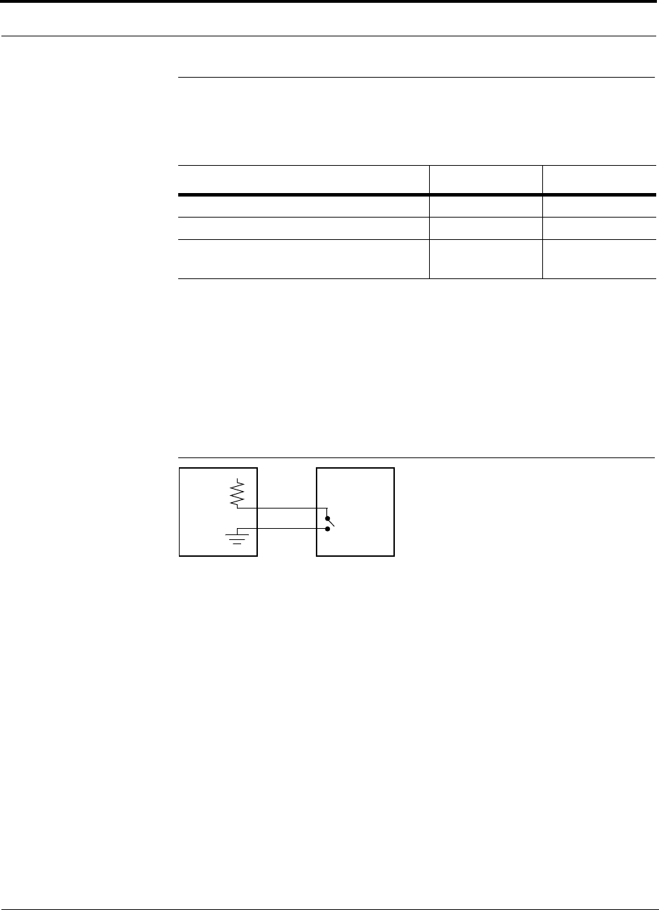
3.3 LGCell Main Hub Alarm
The two error connections, Major Error and Error Latch, are relay connections. They
are either open or short circuit as shown in the following table.
• Major Error
The Main Hub senses, then latches, major errors, which can be monitored via the
alarm port’s contact closures. Red or unlit (off) LEDs on the front panel indicate
when an alarm is detected. (Refer to Section 10.2 on page 10-2 for help trouble-
shooting using LEDs.)
The major error contact can be brought back to the BTS for alarm monitoring if the
BTS provides +40V DC or less.
Figure 3-8 Monitoring Main Hub Alarms from the BTS
• Error Latch
The error latch provides historical information for troubleshooting when you use
an external alarm monitor. The recommended method of clearing an error latch is
to connect pin 8 (error reset) to pin 1 (+10V) for at least one second. You can
power cycle the unit to clear the error latch, but if you are not monitoring alarms
externally, there is no need to do this. Normal operation of the system will not be
affected by an uncleared error latch.
Operation Major Error Error Latch
Proper Operation Short Circuit Short Circuit
Error Open Circuit Open Circuit
Error Latch indicates that there has been a
major error which was cleared.
Short Circuit Open Circuit
BTS Main
Hub

PN 8100-40 Help Hot Line (U.S. only): 1-800-530-9960 3-9
620004-0 Rev. E
LGCell Main Hub Specifications
3.4 LGCell Main Hub Specifications
Note that for dual band systems, the specifications are per band.
Table 3-2 Main Hub Specifications
Specification Description
Dimensions (H × W × D) 44.5 mm × 438 mm × 229 mm (1.75 in. × 17.25 in. × 9 in.); 1U
Weight < 3 kg (< 6.5 lb)
Operating Temperature 0° to 45°C (32° to 113°F)
Operating Humidity, non-condensing 5% to 95%
Clearance Front: minimum 50 mm (2 in.)
Rear: minimum 76 mm (3 in.)
RF Connectors 3, N-type female
Remote Alarm Connector, contact closure 1, 9-pin D-sub female
1, 25-pin D-sub female (not used)
Multimode Fiber Connectors 4 pair, ST female
LED Alarm and Status Indicators MMF Port: Link Status, Sync (4 pair)
Unit Functionality: Sync, Power (1 pair)
AC Power (Universal)
Typical
Maximum
117V AC, 0.22 amp @ 60 Hz
230V AC, 0.11 amp @ 50 Hz
117V AC, 0.30 amp @ 60 Hz
230V AC, 0.15 amp @ 50 Hz
Power Consumption
Typical
Maximum
25 W
35 W
Frequencies • 800 MHz Cellular
• 800 MHz iDEN
• 900 MHz GSM
• 900 MHz EGSM
• 1800 MHz DCS
• 1900 MHz PCS
• 800 MHz Cellular & 1900 MHz PCS
• 900 MHz GSM & 1800 MHz DCS
• 900 MHz EGSM & 1800 MHz DCS
• 1800 MHz DCS & 1800 MHz DCS
MTBF (hours) 298,000

LGCell Main Hub
3-10 LGCell 4.0 Installation, Operation, and Reference Manual PN 8100-40
620004-0 Rev. E
PN 8100-40 LGCell 4.0 Installation, Operation, and Reference Manual 4-1
620004-0 Rev. E
SECTION 4 LGCell Expansion Hub
The Expansion Hub is LGCell’s intermediate distribution point. It converts optical
signals that it receives from the Main Hub to intermediate frequency (IF) electrical
signals that it transmits over Cat-5 cable to the RAUs.
Figure 4-1 The Expansion Hub in an LGCell 1-1-1 Configuration*
LGCell Expansion Hub Features
• Mounts in a standard 19 in. (483 mm) equipment rack
• Connects to Main Hub using 62.5µm/125µm multimode fiber (MMF) cable
• Supports up to four RAUs per band using Cat-5 UTP/STP cable with RJ-45 con-
nectors
• Provides DC power to RAUs through the UTP/STP cable
• Has easily accessible front panel connectors
• Displays its status and the status of attached RAUs with front panel LEDs
• Communicates with Main Hub for system alarm status
RAU
Multimode Fiber
between Main Hub
and Expansion Hub
Cat-5 UTP/STP
between Expansion Hub and RAU
and Base Station or Repeater
Coaxial Cable between
Coaxial Cable between Main Hub
AC POWER
LGCell
TM
Main Hub
SYNC
POWER
LINK
SYNC
STATUS
DOWN UP
1
LINK
SYNC
STATUS
DOWN UP
2
LINK
SYNC
STATUS
DOWN UP
3
LINK
SYNC
STATUS
DOWN UP
4
TO EXPANSION HUB PORTS
AC POWER
LGCell
TM
Expansion Hub
SYNC
POWER
SYNC
LINK
STATUS
ANTENNA PORTS
DOWN UP
MAIN HUB PORT
RAU and Passive Antenna
*1-1-1 configuration = 1 Main Hub, 1 Expansion Hub, and 1 Remote Access Unit
LGCell Expansion Hub
4-2 LGCell 4.0 Installation, Operation, and Reference Manual PN 8100-40
620004-0 Rev. E
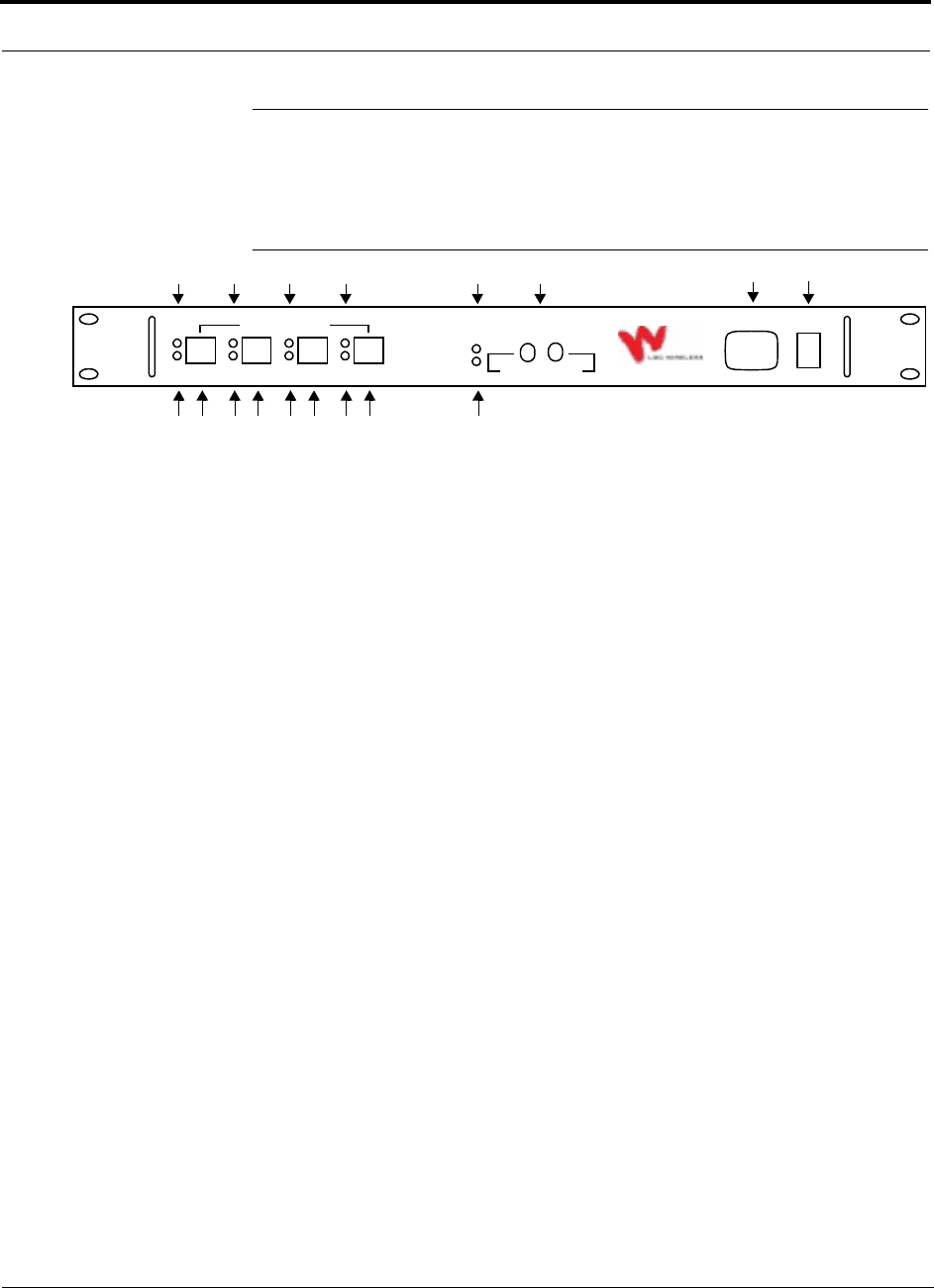
4.1 LGCell Expansion Hub Front Panel
The front panel of an Expansion Hub is shown in the following figure.
Figure 4-2 Front Panel of an Expansion Hub
1. AC power cord connector
2. Power On/Off switch
3. MMF Port (labeled MAIN HUB)
• One standard female ST optical connector for MMF downlink (labeled DOWN)
• One standard female ST optical connector for MMF uplink (labeled UP)
4. One LED for unit sync status (labeled SYNC)
5. One LED for unit power status (labeled POWER)
6. Four standard Cat-5 UTP/STP cable RJ-45 female connectors (labeled ANTENNA
PORTS 1, 2, 3, and 4)
7. One LED per RJ-45 connector for link status (labeled LINK STATUS)
8. One LED per RJ-45 connector for sync status (labeled SYNC)
1 2
3
5
6
AC POWER
LGCell
TM
Expansion Hub
SYNC
POWER
SYNC
LINK
STATUS
ANTENNA PORTS
DOWN UP
MAIN HUB PORT
4
8
7
68
7
68
7
68
7
PN 8100-40 Help Hot Line (U.S. only): 1-800-530-9960 4-3
620004-0 Rev. E
LGCell Expansion Hub Front Panel
4.1.1 MMF Downlink/Uplink Port
The Expansion Hub’s MMF downlink/uplink port transmits and receives optical sig-
nals to/from the Main Hub using industry-standard 62.5µm/125µm MMF cable.
There is one MMF port (labeled MAIN HUB) on the Expansion Hub’s front panel. The
MMF port has two female ST optical connectors: one for downlink (input) and one
for uplink (output).
• MMF Downlink Connector
This female ST optical connector (labeled DOWN) is used to receive downlink opti-
cal signals from the Main Hub.
• MMF Uplink Connector
This female ST optical connector (labeled UP) is used to transmit uplink optical
signals to the Main Hub.
Figure 4-3 MMF Downlink/Uplink Port on the Expansion Hub
Uplink/Output to Main Hub
Downlink/Input from Main Hub
Female ST connector
Female ST connector
AC POWER
LGCell
TM
Expansion Hub
SYNC
POWER
SYNC
LINK
STATUS
ANTENNA PORTS
DOWN UP
MAIN HUB PORT
LGCell Expansion Hub
4-4 LGCell 4.0 Installation, Operation, and Reference Manual PN 8100-40
620004-0 Rev. E
4.1.2 RJ-45 Ports
The Expansion Hub’s RJ-45 ports are for the Cat-5 UTP/STP cables that are used to
transmit and receive electrical signals to/from up to four RAUs. There are four ports
on the Expansion Hub’s front panel.
Figure 4-4 RJ-45 Ports on the Expansion Hub
Port Disconnect Memory
The Expansion Hub detects when active UTP/STP cable and RAUs are connected to
its RJ-45 ports. An alarm is issued and latched if you disconnect an active UTP/STP
cable or an attached RAU. The port disconnect memory and alarm are cleared if you
reconnect the cable into the same functioning port. The error latch remains active
until power is cycled. If you do not want to use that port, you should cycle the Expan-
sion Hub’s power to clear the port disconnect memory and the error latch.
Female RJ-45 ports
AC POWER
LGCell
TM
Expansion Hub
SYNC
POWER
SYNC
LINK
STATUS
ANTENNA PORTS
DOWN UP
MAIN HUB PORT
for RAU connection
(4 per hub)
PN 8100-40 Help Hot Line (U.S. only): 1-800-530-9960 4-5
620004-0 Rev. E
LGCell Expansion Hub Front Panel
4.1.3 Expansion Hub LED Indicators
The front panel of the Expansion Hub has LEDs that provide diagnostic information
and operational status of the unit and attached RAUs.
Figure 4-5 Expansion Hub Front Panel LEDs
The Expansion Hub’s LED indicators are described in the following table.
Table 4-1 Expansion Hub LED Indicators
UTP/STP Port
Indicators/Color
LINK STATUS SYNC Indicates
Green Green RAU is connected and functioning properly.
Green Red RAU is connected but malfunctioning.
Red Green RAU has been disconnected or the cable is cut.
Red Red No RAU is connected.
Unit
Functionality
Indicators Color Indicates
SYNC Green
Off
Expansion Hub is receiving the synchronization signal from the Main Hub.
A fault with the MMF downlink or the unit is faulty.
POWER Green Expansion Hub has power.
AC POWER
LGCell
TM
Expansion Hub
SYNC
POWER
SYNC
LINK
STATUS
ANTENNA PORTS
DOWN UP
MAIN HUB PORT
UTP/STP Port LED Indicators
Unit Functionality LED Indicators
(1 pair per hub)
(1 pair for each RJ-45 connector)
LINK
STATUS
SYNC
SYNC
POWER

LGCell Expansion Hub
4-6 LGCell 4.0 Installation, Operation, and Reference Manual PN 8100-40
620004-0 Rev. E
4.2 LGCell Expansion Hub Rear Panel
The Expansion Hub’s rear panel has one air exhaust vent and no connectors.
4.3 LGCell Expansion Hub Alarm
The Expansion Hub communicates its status and the status of connected RAUs to the
Main Hub over the MMF cable. The Main Hub’s MMF port LEDs can be used to help
troubleshoot downstream problems; however, the LEDs do not indicate which down-
stream unit has the alarm.

PN 8100-40 Help Hot Line (U.S. only): 1-800-530-9960 4-7
620004-0 Rev. E
LGCell Expansion Hub Specifications
4.4 LGCell Expansion Hub Specifications
Note that for dual band systems, the specifications are per band.
Table 4-2 Expansion Hub Specifications
Specification Description
Dimensions (H × W × D) 44.5 mm × 438 mm × 229 mm (1.75 in. × 17.25 in. × 9 in.); 1U
Weight < 3 kg (< 6.5 lb)
Operating Temperature 0° to 45°C (32° to 113°F)
Operating Humidity, non-condensing 5% to 95%
Clearance Front: minimum 50 mm (2 in.)
Rear: minimum 76 mm (3 in.)
RF Connectors 4 ports, RJ-45
Multimode Fiber Connectors 1 pair, ST female
LED Alarm and Status Indicators UTP/STP Port: Link Status, Sync (4 pair)
Unit Functionality: Sync, Power (1 pair)
AC Power (Universal)
Typical
Maximum
117V AC, 0.47 amp @ 60 Hz
230V AC, 0.24 amp @ 50 Hz
117V AC, 0.64 amp @ 60 Hz
230V AC, 0.32 amp @ 50 Hz
Power Consumption
Typical
Maximum
32 W / 55 W with 4 RAUs
45 W / 75 W with 4 RAUs
Frequencies • 800 MHz Cellular
• 800 MHz iDEN
• 900 MHz GSM
• 900 MHz EGSM
• 1800 MHz DCS
• 1900 MHz PCS
• 800 MHz Cellular & 1900 MHz PCS
• 900 MHz GSM & 1800 MHz DCS
• 900 MHz EGSM & 1800 MHz DCS
• 1800 MHz DCS & 1800 MHz DCS
MTBF (hours) 461,000

LGCell Expansion Hub
4-8 LGCell 4.0 Installation, Operation, and Reference Manual PN 8100-40
620004-0 Rev. E
PN 8100-40 LGCell 4.0 Installation, Operation, and Reference Manual 5-1
620004-0 Rev. E
SECTION 5 LGCell Remote Access Unit
The Remote Access Unit (RAU) is an active transceiver that connects to an Expan-
sion Hub using industry-standard Cat-5 UTP/STP cable. The cable delivers radio sig-
nals, control signals, and electrical power to the RAU.
An RAU passes electrical signals between an Expansion Hub and an attached passive
antenna.
Figure 5-1 The Remote Access Unit in an LGCell 1-1-1 Configuration*
LGCell Remote Access Unit Features
• Transmits intermediate frequency (IF) signals to and from Expansion Hub using
Cat-5 UTP/STP cable with RJ-45 connectors
• Converts IF to RF (downlink) and RF to IF (uplink)
• Uses a female SMA connector for connecting to standard passive antennas
• Displays its operational status with LEDs
• Plenum-rated unit
• Mounts above a false ceiling or in a plenum-rated location
RAU
Multimode Fiber
between Main Hub
and Expansion Hub
Cat-5 UTP/STP between
Expansion Hub and RAU
Main Hub and Base
Station or Repeater
Coaxial Cable
Coaxial Cable between
AC POWER
LGCell
TM
Main Hub
SYNC
POWER
LINK
SYNC
STATUS
DOWN UP
1
LINK
SYNC
STATUS
DOWN UP
2
LINK
SYNC
STATUS
DOWN UP
3
LINK
SYNC
STATUS
DOWN UP
4
TO EXPANSION HUB PORTS
AC POWER
LGCell
TM
Expansion Hub
SYNC
POWER
SYNC
LINK
STATUS
ANTENNA PORTS
DOWN UP
MAIN HUB PORT
between RAU and
Passive Antenna
*1-1-1 configuration = 1 Main Hub, 1 Expansion Hub, and 1 Remote Access Unit

LGCell Remote Access Unit
5-2 LGCell 4.0 Installation, Operation, and Reference Manual PN 8100-40
620004-0 Rev. E
5.1 LGCell Remote Access Unit Connectors
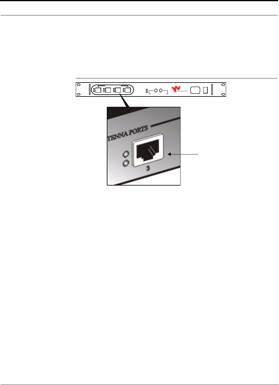
RJ-45 Port
There is one RJ-45 port on each single band RAU, and two ports on each dual band
RAU.
Figure 5-2 RJ-45 Port on a Single Band RAU
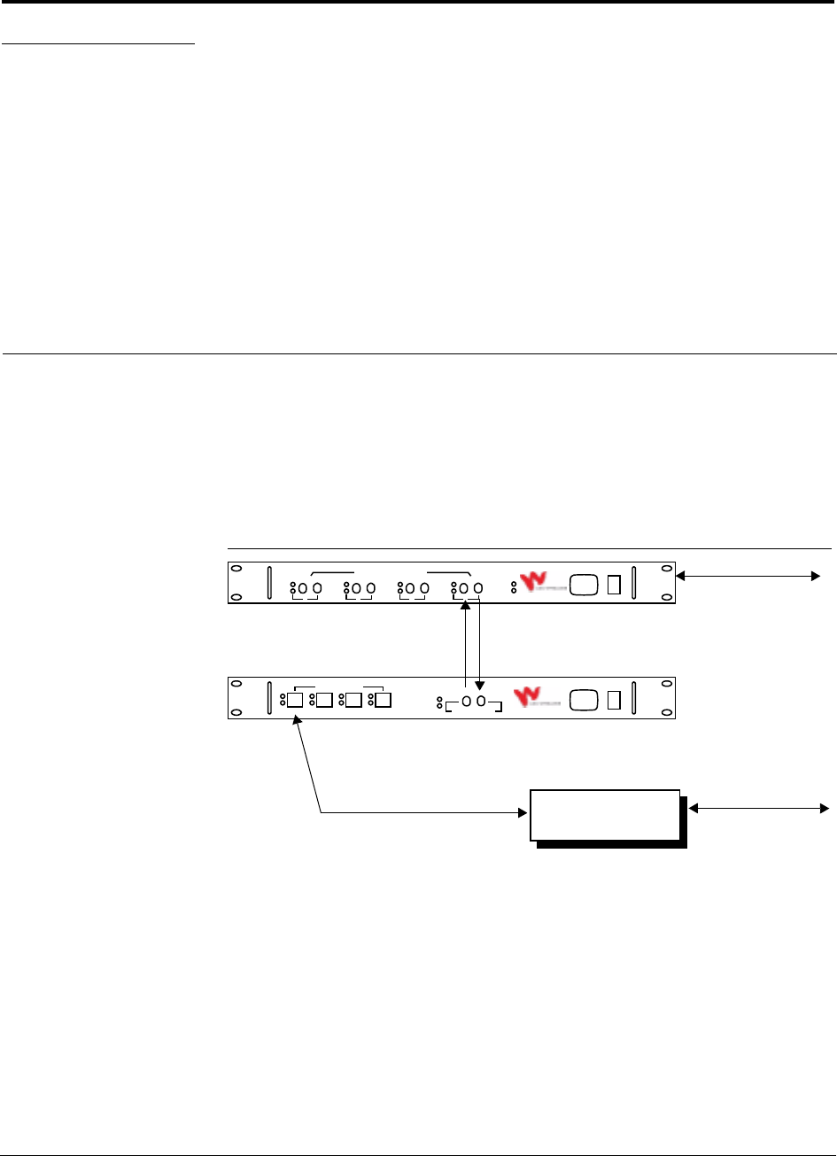
Figure 5-3 RJ-45 Ports on LGCell Dual Band RAUs
1800 MHz
1800 MHz
900 MHz
800/900 MHz and
dual band RAUs
800/1900 MHz
900/1800 MHz and
dual band RAUs
1800/1800 MHz
(vertical style)
(horizontal style)
“Lower” Band
“Upper” Band
800 MHz
“Lower” Band
900 MHz
“Upper” Band
1900 MHz
Bands
(MHz) RAU style
RJ-45 Port
“Lower”
Band
“Upper”
Band
900/1800 Vertical Top (900) Bottom (1800)
1800/1800a
a. On an 1800/1800 MHz dual band RAU, the ports are interchangeable.
It does not matter which Cat-5 cable coming from the 1800/1800 dual
band Expansion Hub you plug into the top or the bottom RJ-45 port.
However, you may want to plug the top 1800 MHz Expansion Hub’s
Cat-5 cable into the top port and the bottom Expansion Hub’s cable into
the bottom port for easier troubleshooting later.
Vertical Top (1800) Bottom (1800)
800/900 Horizontal Left (800) Right (900)
800/1900 Horizontal Left (800) Right (1900)
PN 8100-40 Help Hot Line (U.S. only): 1-800-530-9960 5-3
620004-0 Rev. E
LGCell Remote Access Unit Connectors
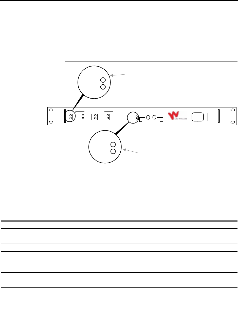
SMA Connector
There is one female SMA connector on a single band RAU, one on the 800/900,
800/1900, and 900/1800 dual band RAUs, and two on the 1800/1800 dual band RAU.
The connector is a duplexed RF input/output port that connects to standard passive
antennas.
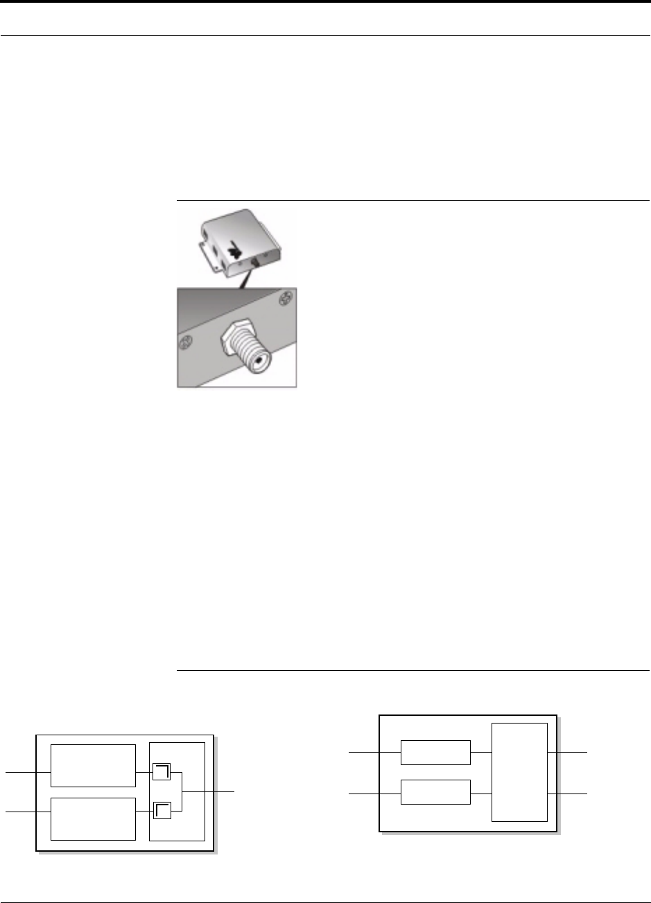
Figure 5-4 SMA Connector on the Single Band RAU
Each 800/900, 800/1900, and 900/1800 dual band RAU has a single female SMA
connector. The RAU uses a diplexer to combine the lower and upper band signals
from the lower and upper band Expansion Hubs for output to a single passive
antenna. Conversely, the uplink signals are separated into lower and upper band sig-
nals and sent to the Expansion Hubs.
The 1800/1800 dual band RAU has two female SMA connectors. The RAU combines
the signals from each of the 1800 MHz bands on the 1800/1800 dual band Expansion
Hub and passes the signals to both SMA connectors. On the uplink, all signals are
sent to both 1800 MHz bands on the 1800/1800 dual band Expansion Hub. When
attaching one passive antenna, terminate the unused connector with an SMA-type
50 ohm terminator (LGC Wireless part number 4100).
Diagrams of the dual band RAUs are shown in the following figure.
Figure 5-5 Block Diagram of the Dual Band RAUs
900 (E)GSM/1800 DCS Dual Band RAU
800 Cellular, Diplexer
STP
STP
RF Out/In
to/from Antenna
800 CDMA + 900 GSM
1800 DCS/1800 DCS Dual Band RAU
1800 DCS(i)
STP
STP
RF Out/In
to/from Antenna
1800 DCS(i) +
1800 DCS(ii)
Combiner
1800 DCS(i) +
1800 DCS(ii)
1800 DCS(ii)
Hybrid
800 Cellular/1900 PCS, and
or 900 (E)GSM
1800 DCS,
or 1900 PCS 900 (E)GSM + 1800 DCS
800 CDMA/900 GSM,
800 Cellular + 1900 PCS
800 CDMA,
900 GSM,
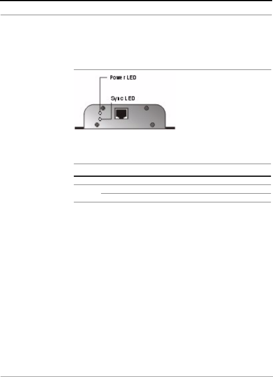
LGCell Remote Access Unit
5-4 LGCell 4.0 Installation, Operation, and Reference Manual PN 8100-40
620004-0 Rev. E
5.1.1 Remote Access Unit LED Indicators
The RAU has LEDs that provide diagnostic information and operational status of the
unit.
Figure 5-6 RAU LEDs
The RAU’s LED indicators are described in the following table.
When the RAU SYNC LED turns red, it indicates that the RF power in the RAU is
shut down. When the fault is corrected, the SYNC LED turns off.
Table 5-1 RAU LED Indicators
LED Color Indicates
POWER Green RAU is receiving power from the connected Expansion Hub.
SYNC Red PLL is not locked or clock power is low.
Off No fault.

PN 8100-40 Help Hot Line (U.S. only): 1-800-530-9960 5-5
620004-0 Rev. E
LGCell Remote Access Unit Alarm
5.2 LGCell Remote Access Unit Alarm
The RAU communicates its status to the Expansion Hub over the Cat-5 cable. The
Expansion Hub, in turn, communicates the status to the Main Hub. The Main Hub’s
MMF port LEDs can be used to help troubleshoot downstream problems; however,
the LEDs do not indicate which downstream unit has the alarm.

LGCell Remote Access Unit
5-6 LGCell 4.0 Installation, Operation, and Reference Manual PN 8100-40
620004-0 Rev. E
5.3 LGCell Remote Access Unit Specifications
Table 5-2 RAU Specifications (Single Band Unless Indicated Otherwise)
Specification Description
Dimensions (H × W × D)
Single Band
Dual Band (vertical): 900/1800, 1800/1800
Dual Band (horizontal): 800/900, 800/1900
36 mm × 110 mm × 140 mm (1.4 in. × 4.3 in. × 5.5 in.)
68 mm × 157 mm × 203 mm (2.7 in. × 6.2 in. × 8 in.)
35 mm × 261 mm × 200 mm (1.4 in. × 10.3 in. × 7.9 in)
Weight
Single Band
Dual Band: all
< 0.4 kg (< 0.9 lb)
< 0.8 kg (< 1.8 lb)
Operating Temperature 0° to 45°C (32° to 113°F)
Operating Humidity, non-condensing 5% to 95%
RF Connectors
Single Band
Dual Band: 900/1800, 800/900, 800/1900
Dual Band: 1800/1800
1 RJ-45; 1, SMA female
2 RJ-45; 1, SMA female
2 RJ-45; 2 SMA female
LED Alarm and Status Indicators Power, Sync
Power Consumption
Typical
Maximum
5.7 W
7.5 W
Frequencies • 800 MHz Cellular*
• 800 MHz iDEN
•900 MHz GSM*
• 900 MHz EGSM
• 1800 MHz DCS
• 1900 MHz PCS
MTBF (hours) 965,000
* The 800 MHz CDMA/900 MHz GSM RAU is designed for use in China. It comprises one 800 MHz Cellular and
one 900 MHz GSM single band RAU as well as a diplexer that filters and combines the bands.

PN 8100-40 Help Hot Line (U.S. only): 1-800-530-9960 5-7
620004-0 Rev. E
LGCell Remote Access Unit Specifications
The RF passband for the 800 MHz CDMA/900 MHz GSM RAU is shown in
Table 5-3.
Table 5-3 RF Frequency
Parameter
800 MHz CDMA 900 MHz GSM
Downlink Uplink Downlink Uplink
RF Frequency (full band) 870 to 880 MHz 825 to 835 MHz 954 to 909 MHz 909 to 915 MHz
Bandwidth 10 MHz 10 MHz 6 MHz 6 MHz

LGCell Remote Access Unit
5-8 LGCell 4.0 Installation, Operation, and Reference Manual PN 8100-40
620004-0 Rev. E
5.4 Choosing Passive Antennas
Typically, omni-directional and directional passive antennas are used. Typical
antenna gain is approximately 3 dBi for omni-directional antennas and 7 dBi for
directional antennas. Antenna manufacturer specifications should be considered
when selecting antennas.
Antenna selection considerations include:
• Antenna gain
• Antenna type (omni or directional, etc.)
• Performance
• Appearance (important to the building owner)
• Mounting type (ceiling mount, wall mount)
Refer to the LGC Wireless Complementary Products Catalog or contact your LGC
account manager for a complete list of passive antennas that are available from LGC
Wireless.

PN 8100-40 LGCell 4.0 Installation, Operation, and Reference Manual 6-1
620004-0 Rev. E
SECTION 6 Managing and Planning an
LGCell Project
This section provides information to assist in managing and planning an LGCell sys-
tem installation.
• Section 6.1 Managing an LGCell Project . . . . . . . . . . . . . . . . . . . . . . . . . . . . 6-2
• Section 6.2 Planning an LGCell Installation . . . . . . . . . . . . . . . . . . . . . . . . . . 6-5
• Section 6.3 Installation Checklist . . . . . . . . . . . . . . . . . . . . . . . . . . . . . . . . . . 6-8
• Section 6.4 System Optimization and Commissioning . . . . . . . . . . . . . . . . . . 6-9
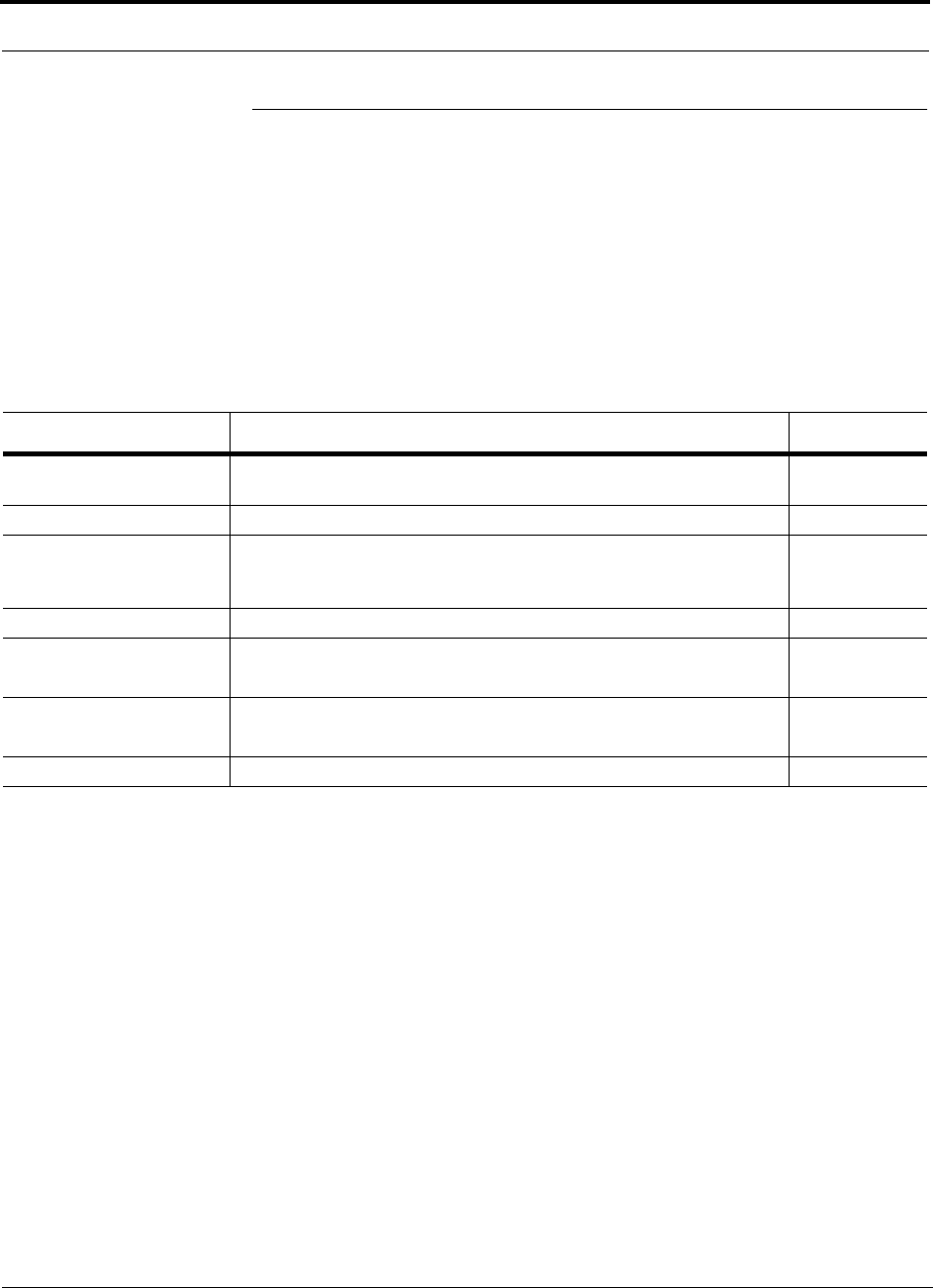
Managing and Planning an LGCell Project
6-2 LGCell 4.0 Installation, Operation, and Reference Manual PN 8100-40
620004-0 Rev. E
6.1 Managing an LGCell Project
Proper project management is instrumental in providing timely and accurate deploy-
ment of the LGCell system. It is beneficial to have one person manage and coordinate
all aspects of the project: planning, designing, and installing the equipment. The
project manager is the person responsible for assigning tasks and ensuring scheduled
work is performed on time. The project manager also acts as the coordinator between
all the people involved in the project.
The following table shows an estimated timeline for project management.
Table 6-1 Project Management Estimated Timeline
Description Details Time Interval
Detailed site
walk-through/RF survey
Prepare installation information, including RF plan, floor plan, equipment
order form, and final design documents.
1 to 2 weeks
Order LGCell equipment Get all parts and accessories required. 8 weeks*
*Standard delivery after receipt of order.
Select cabling contractor Complete installation statement of work and provide floor plan with equip-
ment locations, cabling runs, and other materials and connections. Get
cabling quotation after walk-through.
2 weeks
Install cable Monitor installation. 1 to 5 days
Install LGCell Review installation checklist and prepare all materials.
Refer to Section 6.3 on page 6-8.
1 to 3 days
Test installation and RF
coverage
Be sure there are no uncovered areas.
Refer to Section 6.4 on page 6-9.
1 hour per RAU
Generate as-built document Prepare site plan diagram and coverage performance. 1 to 5 days

PN 8100-40 Help Hot Line (U.S. only): 1-800-530-9960 6-3
620004-0 Rev. E
Managing an LGCell Project
6.1.1 Project Management Responsibilities
Project management functions are performed throughout the duration of the project,
from Site Survey through Commissioning, and include the following:
Lead Project Team
• Identify all project participants and document contact information
• Initiate project kick-off meeting
• Provide coordination of all participants
• Provide regular status reports to all participants including the end-user
Define Scope of Project
• Obtain system approval from all participants
• Define site coverage requirements
• Identify critical path items
• Identify all special requirements or potential “roadblocks”
• Plan installation time requirements
Conduct RF Site Survey
• Review/confirm the preliminary signal readings and results of the RF Site Survey,
whether conducted by LGC Wireless or others
• Identify RF project changes and/or restrictions
Prepare Site for Installation
• Conduct site walk-through with all appropriate participants
• Coordinate required permits
• Determine material receiving/storage/disbursement location
• Engage and contract with the cabling sub-contractor
• Schedule material delivery
• Coordinate and manage the installation, termination, and testing of required cables
(MMF, UTP/STP, coaxial)
• Coordinate with the base station vendor for the integration of the LGCell system
• Coordinate with the service provider for frequency allocation
• Coordinate the installation of any required AC power, power systems, or power
equipment
Manage Installation of System
• Establish and distribute Installation Schedule
• Confirm cable installation if provided by third-party company
• Confirm antenna locations and selection
• Obtain approval of the Installation Plan from primary participants and the end-user
• Conduct pre-installation inspection
• Coordinate installation of the LGCell equipment
• Coordinate installation of antennas

Managing and Planning an LGCell Project
6-4 LGCell 4.0 Installation, Operation, and Reference Manual PN 8100-40
620004-0 Rev. E
Manage System Commissioning
• Coordinate system test
• Coordinate RF signal and coverage tests
• Coordinate complete RF system test with required participants
Manage System Acceptance
• Coordinate final inspection with required participants
• Prepare System Acceptance Document
• Issue System Acceptance Document
• Prepare As-Built Documents

PN 8100-40 Help Hot Line (U.S. only): 1-800-530-9960 6-5
620004-0 Rev. E
Planning an LGCell Installation
6.2 Planning an LGCell Installation
Preliminary Planning
• Complete a preliminary system design for current requirements
Compile all of the pertinent information to determine a preliminary system design.
• Determine design requirements
Consult with the end user, the service provider, and the equipment vendors to
determine system requirements.
• Analyze floor plans
Review the building floor plans to determine approximate antenna locations and
possible locations of equipment rooms. Also, where possible on the floor plans,
check for various types of construction materials and installation restrictions.
Preliminary System Design
• Compute equipment requirements for current traffic rates
Base this on the voice channels required and equipment parameters of the base sta-
tion specified for the system (requires input from service provider RF Engineer).
• Compute equipment requirements for expansion to future traffic rates
Base this on customer requirements and equipment parameters of the base station
specified for the system.
• Make recommendations for a system design for future traffic requirements
Provide a possible migration plan to achieve future capacity and coverage require-
ments, perhaps including provisions for additional equipment and/or sectorization
of the existing cells.
Site Survey
• Conduct on-site RF site evaluation
Conduct in-building signal level tests after the preliminary design is completed.
Using a test transmitter, introduce an RF signal at the approximate antenna loca-
tions and record the signal levels on a copy of the floor plan.
Conduct a physical review of the building to determine types of construction mate-
rials in the floors and walls, and amount of “clutter” in the building. (Clutter is
anything that can block or reduce the RF signal coverage.) These will help deter-
mine the expected coverage area; the in-building signal loss due to walls, furniture,
equipment, people, etc.; and the proposed equipment locations and cabling require-
ments.
Identify AC power requirements and extra equipment (cabinets, cable trays, cable
racks, etc.)

Managing and Planning an LGCell Project
6-6 LGCell 4.0 Installation, Operation, and Reference Manual PN 8100-40
620004-0 Rev. E
Frequency Planning
• Coordinate frequency planning with local carriers
Discuss with the local carrier the channel requirements for the system.
Final System Design
• Complete final design
Generate a final design based on preliminary design, results of RF tests, discus-
sions with all appropriate parties involved in the project, and the site evaluation.
• Create final equipment list
Generate a final equipment requirement list based on the final system design.
• Design review
Discuss the final system design with all appropriate parties involved in the project.
• RF Survey Report
Generate an RF Survey Report documenting all design information that you gath-
ered.
• Traffic analysis of current requirements
Determine capabilities in terms of current and future capacity, coverage, and qual-
ity of service.
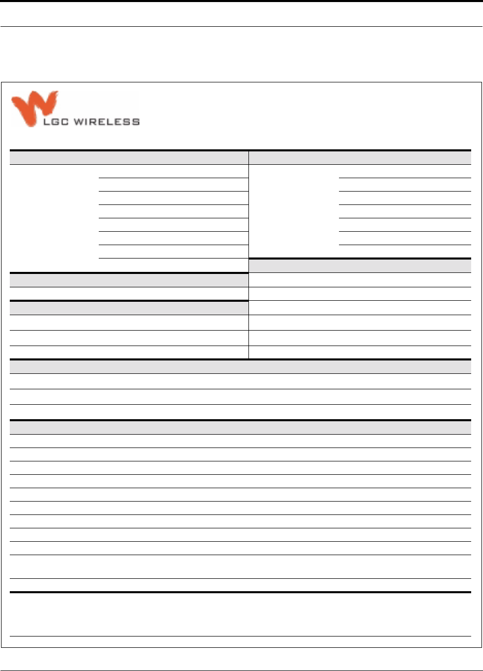
PN 8100-40 Help Hot Line (U.S. only): 1-800-530-9960 6-7
620004-0 Rev. E
Planning an LGCell Installation
6.2.1 Site Survey Questionnaire
Project Information End-User Information
Project Name: End-User:
Purchaser Address: Site Address:
Company Name: Contact:
Contact: Phone:
Phone: E-mail:
E-mail: BTS Information
Type of System Enhancement Manufacturer:
Coverage Capacity (BTS) Wireless Office Model No:
Building Information No. of Carriers:
Are floor plans available (including map scale?) Yes No No. of Subscribers:
Is outdoor coverage required? Yes No BHCR? Yes No
Erlangs/Sub:
Select the Downlink Power, Frequency, Protocol, and Band to Operate Under
Downlink Power at Mobile (dBm): Select One –65 –70 –75 –80 –85 (default) –90 –95
Frequencies (MHz): Select all that apply 800 900 GSM 900 EGSM 1800 1900
Protocol: GSM TDMA CDMA SMR/iDEN AMPS
Additional Questions Select One
Are exposed antennas tolerated inside? Yes No Unsure
Are exposed antennas tolerated outside? Yes No Unsure
Are locations above ceiling/closets available for mounting equipment? Yes No Unsure
Have available mounting locations been identified? (please identify on floor plans) Yes No Unsure
Are 19" equipment racks available? Yes No Unsure
Is AC power available at the Main and Expansion Hubs? Yes No Unsure
Are multimode fiber optic cables available? Yes No Unsure
If on a campus, are single-mode fiber optic cables available? Yes No Unsure
Are Cat-5 UTP/STP runs available? Yes No Unsure
If cabling is not available, will customer mandate a subcontractor?
If yes, provide details in “Comments” section below.
Yes No Unsure
Is a bi-directional amplifier (repeater) needed? Yes No Unsure
Comments: (special installation requirements, subcontractors, coverage areas, contacts, etc.)
2540 Junction Avenue | San Jose, CA 95134 | TEL 408-952-2400 | FAX 408-952-2410
Site Survey Questionnaire

Managing and Planning an LGCell Project
6-8 LGCell 4.0 Installation, Operation, and Reference Manual PN 8100-40
620004-0 Rev. E
6.3 Installation Checklist
Following is an installation checklist.
Table 6-2 Installation Checklist
Item Comments
Floor Plans Detailed floor plans of the project site, suitable for the installation of LGCell
equipment and cable. Equipment locations clearly marked on the plans
RF Site Survey RF signal readings and antenna orientation details from the RF Site Survey,
unless provided by LGC Wireless
Equipment Enclosures/Structures Any enclosures or structures required for the LGCell equipment, i.e., roof-top
structure, unless provided by LGC Wireless
Equipment Racks Procurement and installation of equipment racks, unless provided by LGC
Wireless
Microcellular Base Station Base station installed prior to LGCell equipment installation
Roof-top Antenna/Repeater Roof-top antenna and repeater installed prior to LGCell equipment installation
Cat-5 cabling TIA/EIA 568-A approved; RJ-45 connectors; Absolute Minimum: 10 meters
(33 ft), Recommended Minimum: 20 meters (66 ft), Maximum: 50 meters
(165 ft); Expansion Hubs to RAUs; installed, inspected, tested
Shielded Cat-5 cable (STP) should be used for neutral host systems
MMF 62.5µm/125µm; ST male connectors; up to 1 km (3300 ft); Main Hub to
Expansion Hubs; maximum 3 dB optical loss, including connectors, splices,
etc.; installed, inspected, tested
Coaxial cabling Coax approved; N-type male connectors; repeater or base station to Main Hub;
installed, inspected, tested
Coaxial cabling Coax approved; N-type male connector; RAU to passive antenna; installed,
inspected, tested
Power 110/220V AC power available at hub locations
Equipment on-hand and ready for installation:
LGCell Main Hub(s)
LGCell Expansion Hub(s) 4 per Main Hub
Remote Access Unit(s) 4 per Expansion Hub
Passive Antenna(s) Omni or directional; based on RF design
UPS/Battery If required by customer
Power combiner/divider Required if cascading multiple Main Hubs. N-male to N-male coaxial cables
used to connect power combiner/repeater to Main Hub and base station or
repeater.

PN 8100-40 Help Hot Line (U.S. only): 1-800-530-9960 6-9
620004-0 Rev. E
System Optimization and Commissioning
6.4 System Optimization and Commissioning
After the RF Site Survey is completed and the system is installed, perform the follow-
ing tasks.
Check Installation
• Check installation of the Main Hubs, Expansion Hubs, Remote Access Units, split-
ters/combiners, antennas, etc.
• Confirm all cable connections
• Confirm working condition of LGCell equipment
• Confirm that equipment quantities and equipment locations are documented
• Confirm that all equipment and cables are identified and marked with ID number
Check Cabling
• Review test results of Cat-5 cable (UTP/STP) (conduct cable test if testing has not
already been completed; the results are needed for the As-Built Document)
• Review test results of coaxial cables; at base station to Main Hub and RAU to
antenna
• Confirm and document actual link budget in coaxial cables
Check Optical Loss and Power Levels
• Confirm and document downlink power level out of base station
• Confirm and document downlink power level into Main Hub
• Confirm and document uplink power level out of Main Hub
• Check and document optical loss from Main Hub to Expansion Hub
Verify Coverage
• Conduct floor-by-floor system walk-through, confirming RSSI in all locations of
the coverage area. Document RF signal level readings from all locations onto floor
plan drawings.
• Confirm outside signal levels where required
• Measure RF signal out of equipment, if required
Check Signal Quality
• Check for neighbor channels/frequencies
• Confirm adjacent channel/frequency signal strength
• Check all call quality requirements of the carrier

Managing and Planning an LGCell Project
6-10 LGCell 4.0 Installation, Operation, and Reference Manual PN 8100-40
620004-0 Rev. E
Prepare As-Built Document
Prepare the final As-Built Document to include the following:
• Title Page
• Site Address
• Contact List
• Table of Contents
• Introduction
– Description of system installation including equipment used, unusual appli-
cations or obstacles, etc.
• Equipment Locations
– Descriptions or diagrams of equipment locations within the facility
• Wiring Configuration and Specifications
– Descriptions and tables of MMF and Cat-5 measurements; including Expan-
sion Hub ID numbers, RF signal level readings throughout coverage area,
number of RAUs attached, results of the Cat-5 compliance tests, unusual or
marginal applications, etc.
• Base Station Settings
– Number of channels and sectors, transceiver setting, etc.
– RF power into Main Hub
– Amount of attenuation used
• Coverage Performance
– Description of test method and outcome
• Summary
– Include outstanding issues, future plans, and future considerations
• As-Built Floor Plans

PN 8100-40 LGCell 4.0 Installation, Operation, and Reference Manual 7-1
620004-0 Rev. E
SECTION 7 Designing an LGCell Solution
Designing an LGCell solution is ultimately a matter of determining coverage and
capacity needs. This requires the following steps:
1. Determine the wireless service provider’s requirements.
This information is usually supplied by the service provider:
• Frequency (i.e., 850 MHz)
• Band (i.e., “A” band in the Cellular spectrum)
• Protocol (i.e., TDMA, CDMA, GSM, iDEN)
• Peak capacity requirement (this, and whether or not the building will be split
into sectors, determines the number of carriers that the LGCell will have to
transmit)
• Design goal (RSSI, received signal strength at the wireless handset,
i.e., –85 dBm)
The design goal is always a stronger signal than the cell phone needs. It
includes inherent factors which will affect performance (see Section 7.4.1 on
page 7-29).
• RF source (base station or BDA), type of equipment if possible
2. Determine the power per carrier and input power from the base station or
BDA into the Main Hub: Section 7.1, “Maximum Output Power per Carrier
at RAU,” on page 7-3.
The maximum power per carrier is a function of the number of RF carriers, the
carrier headroom requirement, signal quality issues, regulatory emissions require-
ments, and the LGCell’s RF performance. The power per carrier decreases as the
number of carriers increases.
3. Determine the in-building environment: Section 7.2, “Estimating RF Cover-
age,” on page 7-15.
• Determine which areas of the building require coverage (entire building, public
areas, parking levels, etc.)

Designing an LGCell Solution
7-2 LGCell 4.0 Installation, Operation, and Reference Manual PN 8100-40
620004-0 Rev. E
• Obtain floor plans to determine floor space of building and the wall layout of
the proposed areas to be covered. Floor plans will also be useful when you are
selecting antenna locations.
• If possible, determine the building’s construction materials (sheetrock, metal,
concrete, etc.)
• Determine type of environment
– Open layout (e.g., a convention center)
– Dense, close walls (e.g., a hospital)
– Mixed use (e.g., an office building with hard wall offices and cubicles)
4. Develop an RF link budget: Section 7.4, “Link Budget Analysis,” on page
7-28.
Knowing the power per carrier, you can calculate an RF link budget which is used
to predict how much propagation loss can be allowed in the system, while still
providing satisfactory performance throughout the area being covered. The link
budget is a methodical way to derive a “design goal”. If the design goal is pro-
vided in advance, the link budget is simply: allowable RF loss = max. power per
carrier – design goal.
5. Determine the appropriate estimated path loss slope that corresponds to the
type of building and its layout, and estimate the coverage distance for each
RAU: Section 7.2, “Estimating RF Coverage,” on page 7-15.
The path loss slope (PLS), which gives a value to the RF propagation characteris-
tics within the building, is used to convert the RF link budget into an estimate of
the coverage distance per antenna. This will help establish the LGCell equipment
quantities you will need. The actual path loss slope that corresponds to the spe-
cific RF environment inside the building can also be determined empirically by
performing an RF site-survey of the building. This involves transmitting a cali-
brated tone for a fixed antenna and making measurements with a mobile antenna
throughout the area surrounding the transmitter.
6. Determine the items required to connect to the base station: Section 7.5,
“Connecting a Main Hub to a Base Station,” on page 7-41.
Once you know the quantities of LGCell equipment you will use, you can deter-
mine the accessories (combiners/dividers, surge suppressors, repeaters, attenua-
tors, circulators, etc.) that are required to connect the system to the base station.
The individual elements that must be considered in designing an LGCell solution are
discussed in the following sections.
PN 8100-40 Help Hot Line (U.S. only): 1-800-530-9960 7-3
620004-0 Rev. E
Maximum Output Power per Carrier at RAU
7.1 Maximum Output Power per Carrier at RAU
The following tables show the recommended maximum power per carrier out of the
RAU SMA connector for different frequencies, formats, and numbers of carriers.
These limits are dictated by RF signal quality and regulatory emissions issues. The
maximum input power to the Main Hub is determined by subtracting the system gain
from the maximum output power of the RAU. For most systems the gain is 0 dB.
Exceptions are the duplex port for the Cellular LGCell (30 dB gain) and the duplex
port of the PCS LGCell (40 dB gain).
Therefore, when you connect a Main Hub to a base station or repeater, the RF power
per carrier usually needs to be attenuated in order to avoid exceeding the LGCell’s
maximum composite output power.
Refer to Section 7.6, “Designing for a Neutral Host System,” on page 7-45 when
combining frequencies or protocols on a single Main Hub.
WARNING: Exceeding the maximum input power could cause perma-
nent damage to the Main Hub.
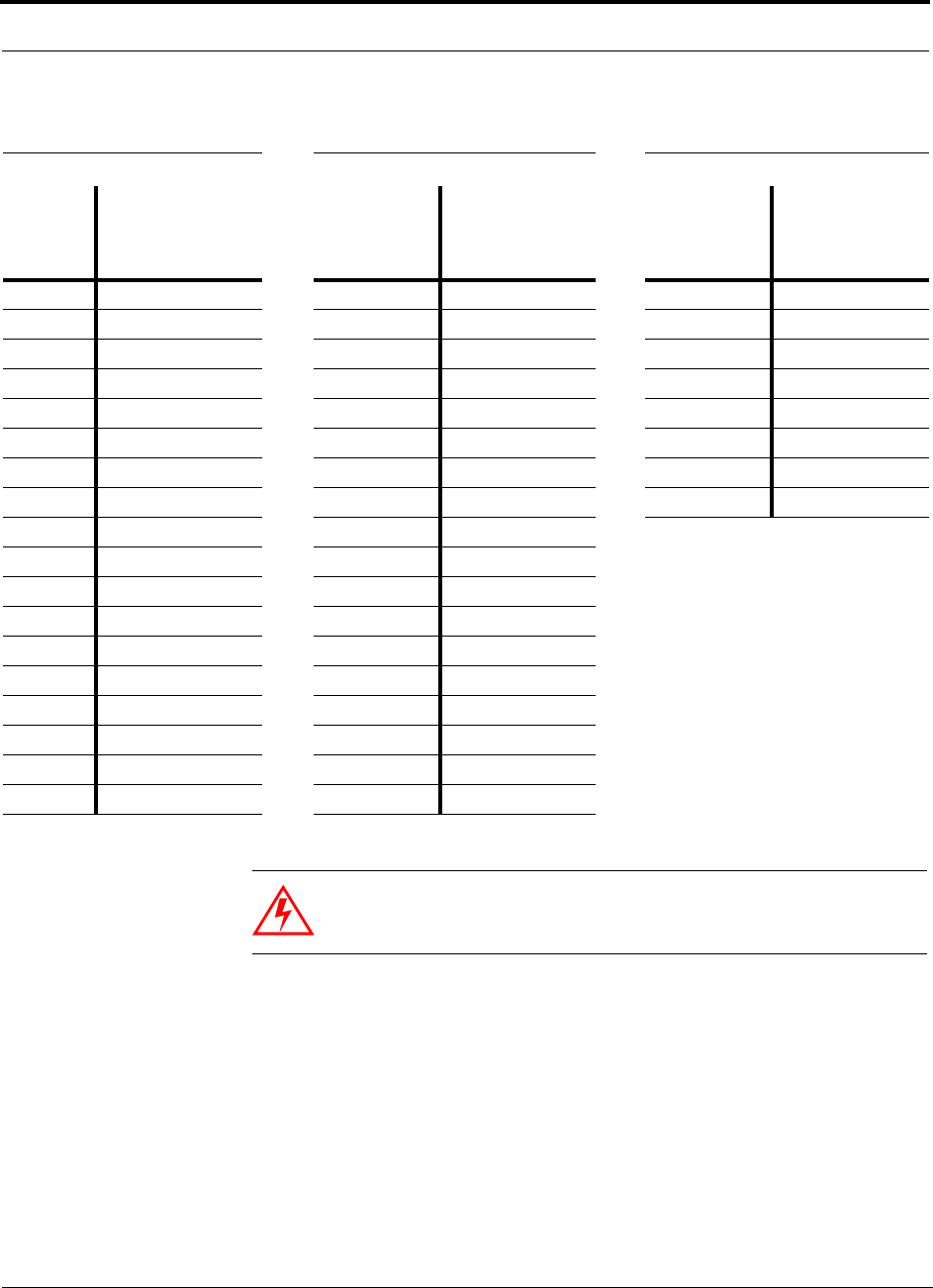
Designing an LGCell Solution
7-4 LGCell 4.0 Installation, Operation, and Reference Manual PN 8100-40
620004-0 Rev. E
WARNING: For 800 MHz Cellular, do not exceed the maximum com-
posite input power of 126mW (+21 dBm) to the Main Hub’s simplex
ports, or 126µW (–9 dBm) to its duplex port at any time.
Table 7-1 800 MHz Cellular Power per Carrier
TDMA AMPS CDMA
No. of
Carriers
Recommended
Maximum
Output PPC
at RAU (dBm)
No. of
Carriers
Recommended
Maximum
Output PPC
at RAU (dBm)
No. of
Carriers
Recommended
Maximum
Output PPC
at RAU (dBm)
1 17.0 1 20.0 1 10.0
212.0 2 14.0 2 7.5
39.0 3 10.5 3 6.0
4 7.0 4 7.5 4 5.0
5 5.5 5 6.0 5 4.0
6 4.5 6 4.5 6 3.5
7 3.5 7 3.5 7 2.5
8 2.5 8 2.5 8 2.0
9 2.0 9 2.0
10 1.5 10 1.0
11 1.0 11 1.0
12 0.5 12 0.5
13 0.5 13 0.0
14 0.0 14 –0.5
15 –0.5 15 –0.5
16 –0.5 16 –1.0
20 –1.5 20 –2.0
30 –3.5 30 –4.0
Note: These specifications are for downlink power at the RAU output (excluding antenna) for single-protocol applications.
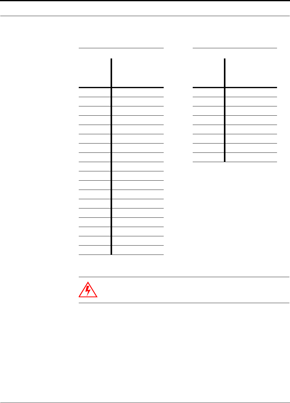
PN 8100-40 Help Hot Line (U.S. only): 1-800-530-9960 7-5
620004-0 Rev. E
Maximum Output Power per Carrier at RAU
WARNING: For 800 MHz iDEN/CDMA, do not exceed the maximum
composite input power of 126mW (+21 dBm) to the Main Hub’s duplex
and/or simplex ports at any time.
Table 7-2 800 MHz iDEN/CDMA Power per Carrier
iDEN CDMA
No. of
Carriers
Recommended
Maximum
Output PPC
at RAU (dBm)
No. of
Carriers
Recommended
Maximum
Output PPC
at RAU (dBm)
110.0 1 9.0
2 7.0 2 6.5
3 4.5 3 5.0
4 3.0 4 4.0
5 2.0 5 3.0
6 1.0 6 2.5
7 0.0 7 1.5
8–0.5 8 1.0
9–1.0
10 –1.5
11 –2.0
12 –2.5
13 –3.0
14 –3.0
15 –3.5
16 –4.0
20 –5.0
30 –6.5
Note: These specifications are for downlink power at the RAU output (excluding antenna) for sin-
gle-protocol applications.
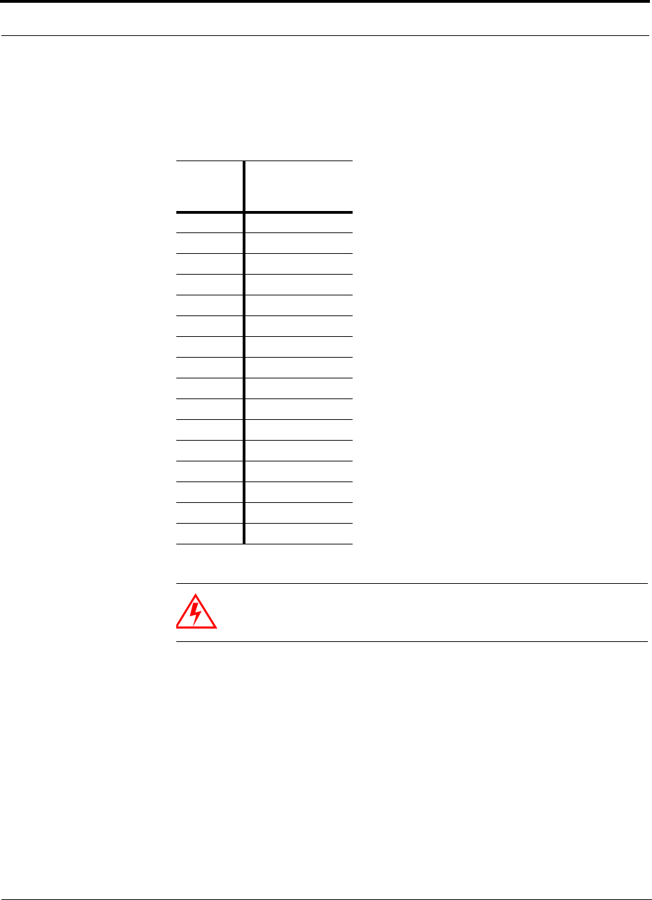
Designing an LGCell Solution
7-6 LGCell 4.0 Installation, Operation, and Reference Manual PN 8100-40
620004-0 Rev. E
WARNING: For 900 MHz GSM or EGSM, do not exceed the maxi-
mum composite input power of 126mW (+21 dBm) to the Main Hub’s
duplex and/or simplex ports at any time.
Table 7-3 900 MHz GSM or EGSM Power per Carrier
The 900 MHz LGCell systems also are approved for use with paging and two-way messag-
ing in the U.S. and Canada.
No. of
Carriers
Maximum
Output PPC
at RAU (dBm)
18.0
24.0
32.0
41.0
50.0
6 –1.0
7 –1.5
8 –2.0
9 –2.5
10 –2.5
11 –3.0
12 –3.5
13 –3.5
14 –4.0
15 –4.0
16 –4.5
Note: These specifications are for downlink power at the RAU output (excluding antenna).
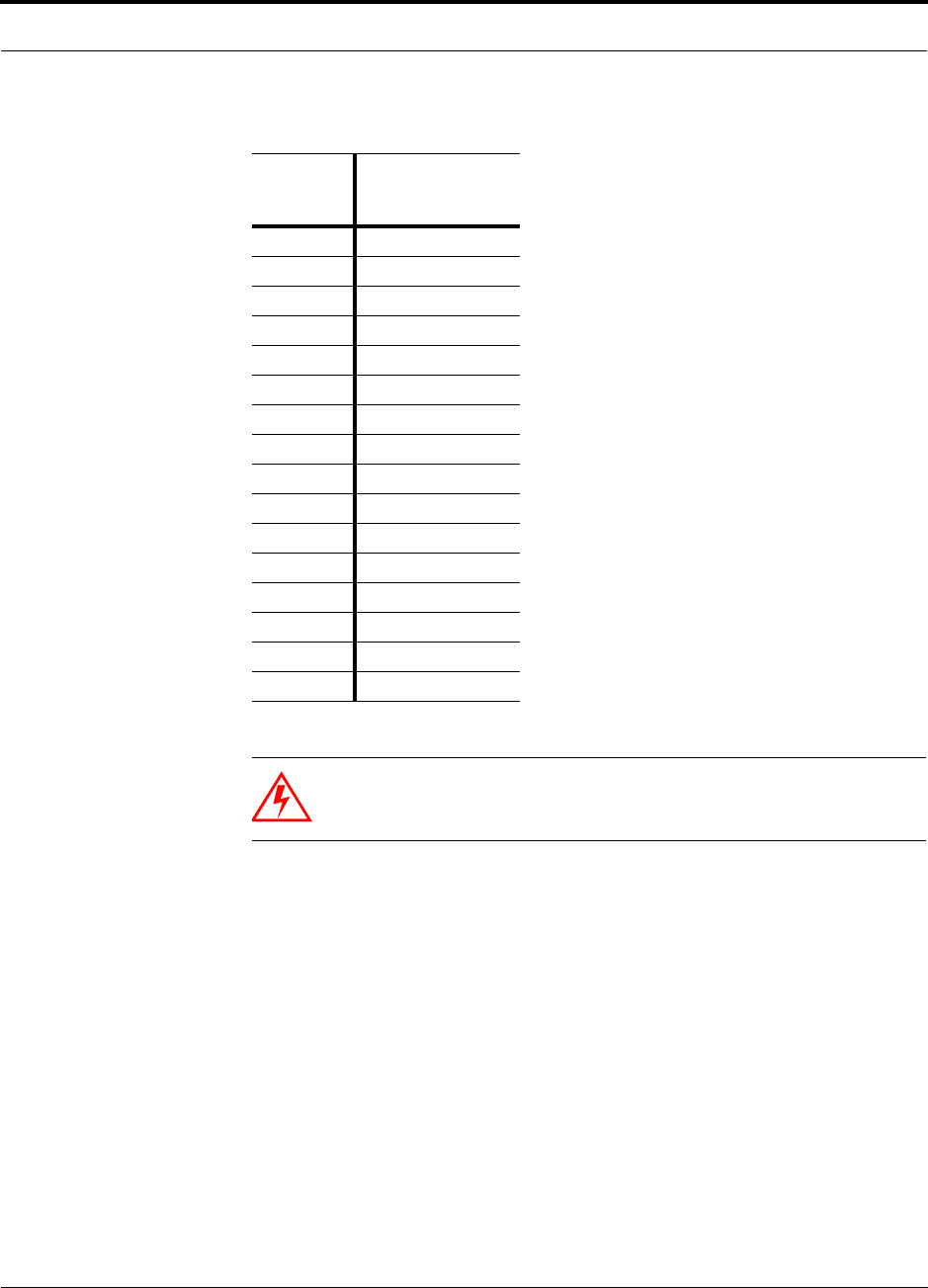
PN 8100-40 Help Hot Line (U.S. only): 1-800-530-9960 7-7
620004-0 Rev. E
Maximum Output Power per Carrier at RAU
WARNING: For 1800 MHz DCS (GSM), do not exceed the maximum
composite input power of 126mW (+21 dBm) to the Main Hub’s duplex
and/or simplex ports at any time.
Table 7-4 1800 MHz DCS (GSM) Power per Carrier
No. of
Carriers
Maximum
Output PPC
at RAU (dBm)
18.0
25.5
33.5
42.0
51.0
60.5
70.0
8–0.5
9–1.0
10 –1.5
11 –1.5
12 –2.0
13 –2.5
14 –2.5
15 –3.0
16 –3.0
Note: These specifications are for downlink power at the RAU output (excluding antenna).
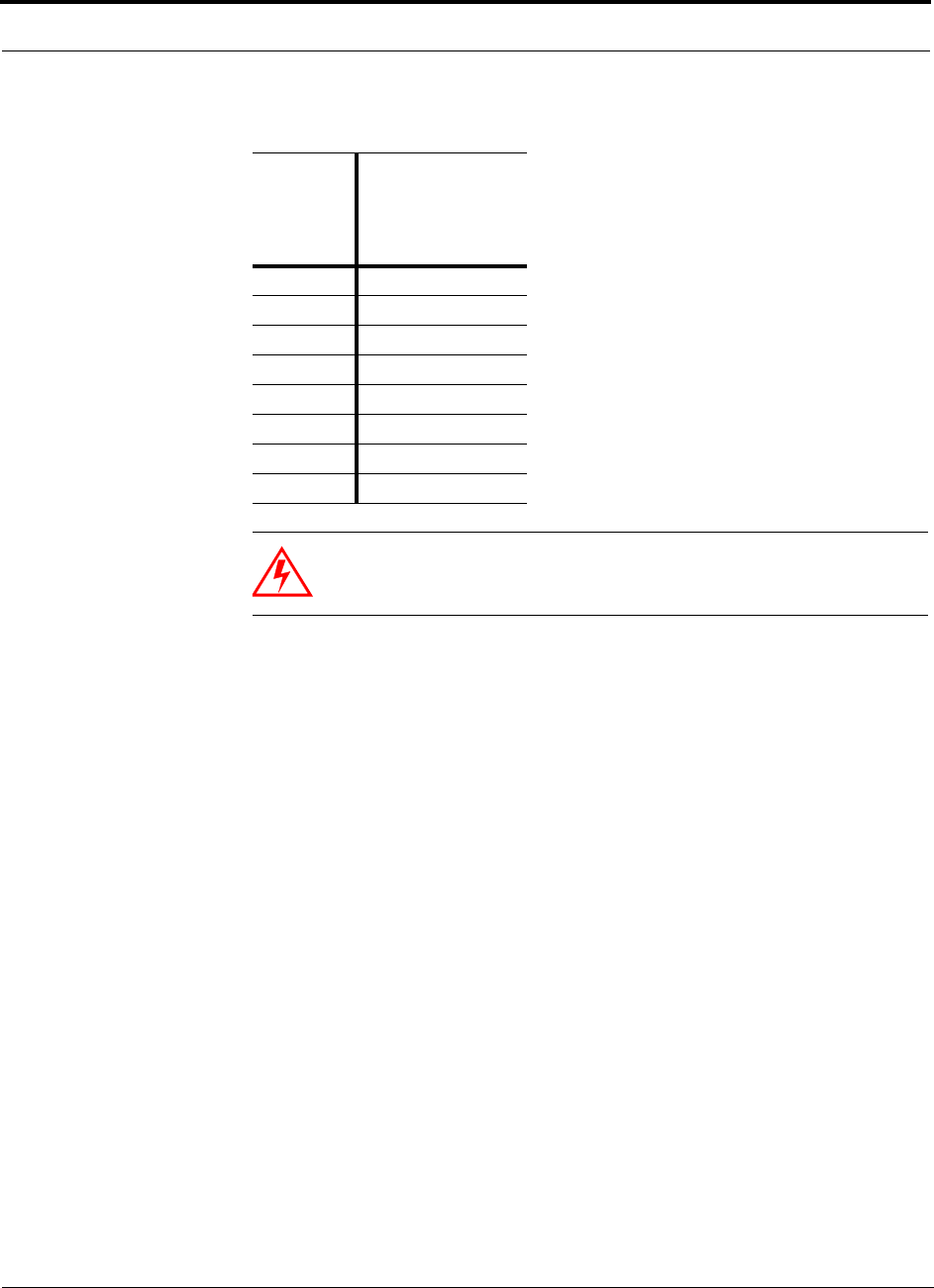
Designing an LGCell Solution
7-8 LGCell 4.0 Installation, Operation, and Reference Manual PN 8100-40
620004-0 Rev. E
WARNING: For 1800 MHz CDMA (Korea), do not exceed the maxi-
mum composite input power of 126mW (+21 dBm) to the Main Hub’s
duplex and/or simplex ports at any time.
Table 7-5 1800 MHz CDMA (Korea) Power per Carrier
No. of
Carriers
Recommended
Maximum
Output PPC
at RAU
(dBm)
18.0
25.5
34.0
43.0
52.0
61.5
70.5
80.0
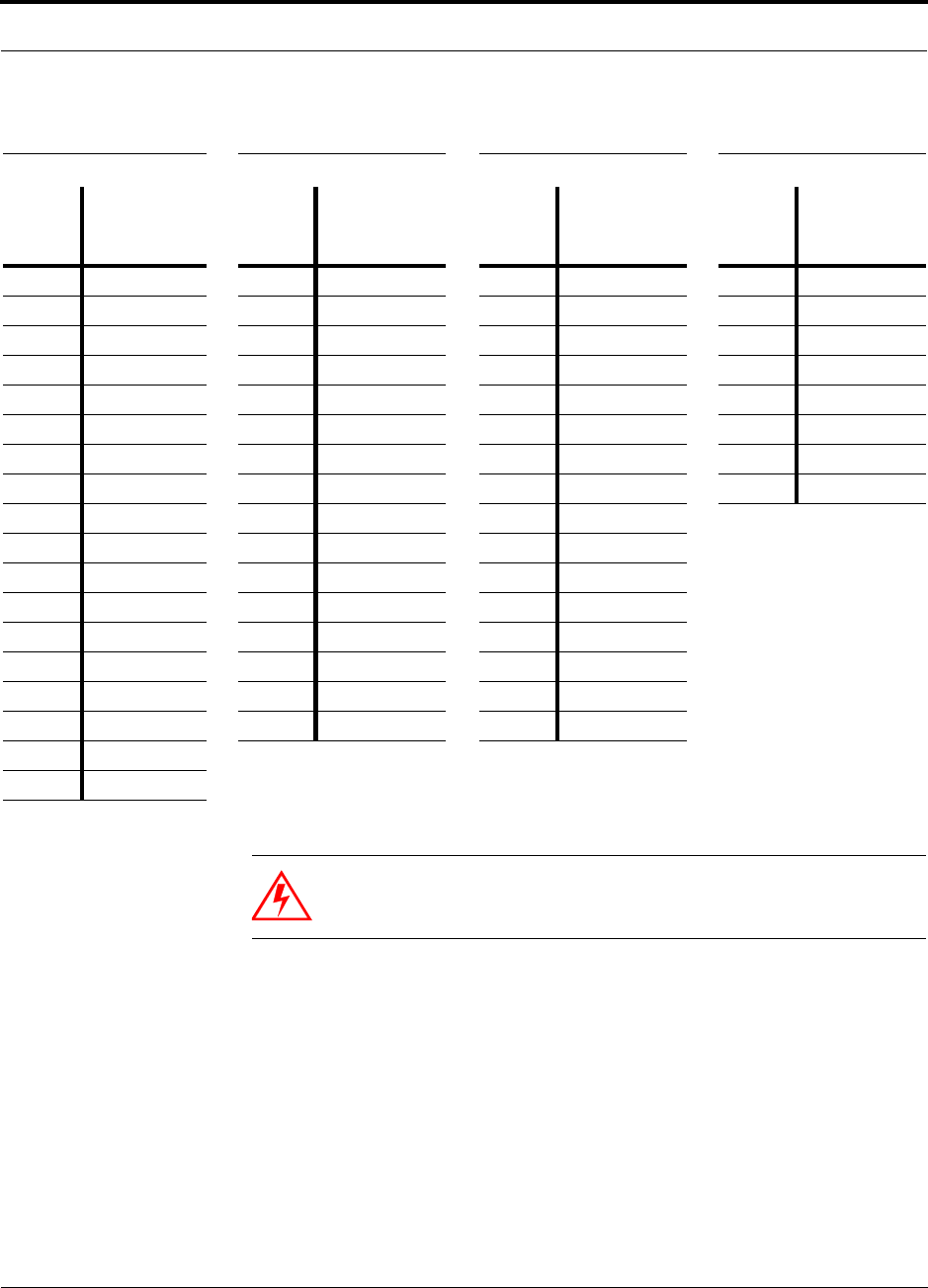
PN 8100-40 Help Hot Line (U.S. only): 1-800-530-9960 7-9
620004-0 Rev. E
Maximum Output Power per Carrier at RAU
WARNING: For 1900 MHz PCS, do not exceed the maximum compos-
ite input power of 126mW (+21 dBm) to the Main Hub’s simplex ports,
or 12.6µW (–19 dBm) to its duplex port at any time.
Table 7-6 1900 MHz PCS Power per Carrier
TDMA GSM EDGE CDMA
No. of
Carriers
Recommended
Maximum
Output PPC
at RAU (dBm) No. of
Carriers
Recommended
Maximum
Output PPC
at RAU (dBm) No. of
Carriers
Recommended
Maximum
Output PPC
at RAU (dBm) No. of
Carriers
Recommended
Maximum
Output PPC
at RAU (dBm)
1 17.0 1 20.0 1 17.0 1 10.0
2 12.0 2 8.0 2 8.0 2 7.5
3 9.0 3 6.0 3 6.0 3 6.0
4 7.0 4 5.0 4 5.0 4 5.0
5 5.5 5 4.0 5 4.0 5 4.0
6 4.5 6 3.0 6 3.0 6 3.5
7 3.5 7 2.5 7 2.5 7 2.5
8 2.5 8 2.0 8 2.0 8 2.0
9 2.0 9 1.5 9 1.5
10 1.5 10 1.5 10 1.0
11 1.0 11 1.0 11 0.5
12 0.5 12 0.5 12 0.0
13 0.5 13 0.5 13 0.0
14 0.0 14 0.0 14 –0.5
15 –0.5 15 0.0 15 –1.0
16 –0.5 16 –0.5 16 –1.0
20 –1.5
30 –3.5
Note: These specifications are for downlink power at the RAU output (excluding antenna) for single-protocol applications.
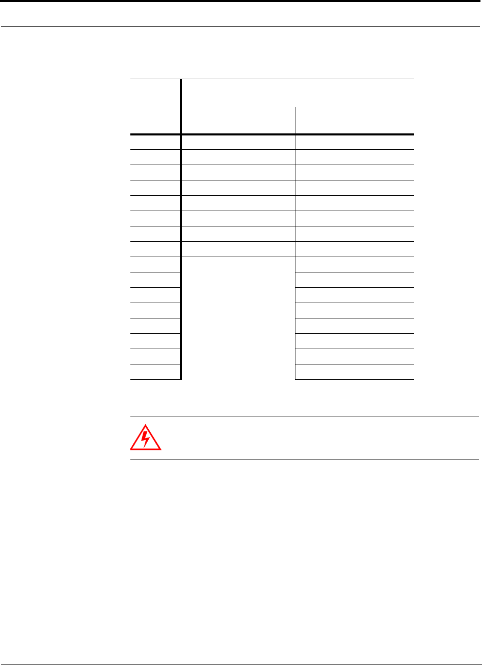
Designing an LGCell Solution
7-10 LGCell 4.0 Installation, Operation, and Reference Manual PN 8100-40
620004-0 Rev. E
WARNING: For 800 MHz CDMA or 900 MHz GSM, do not exceed
the maximum composite input power of 126mW (+21 dBm) to the Main
Hub’s simplex ports, or 126µW (–9 dBm) to its duplex port at any time.
Table 7-7 800 MHz CDMA and 900 MHz GSM Power per Carrier
No. of
Carriers
Recommended Maximum Output Power per
Carrier at RAU (dBm)
800 MHz CDMA
(Lower Band)
900 MHz GSM
(Upper Band)
18.5 6.5
26.0 2.5
34.5 0.5
4 3.5 –0.5
5 2.5 –1.5
6 2.0 –2.5
7 1.0 –3.0
8 0.5 –3.5
9–4.0
10 –4.0
11 –4.5
12 –5.0
13 –5.0
14 –5.5
15 –5.5
16 –5.5
Note: These specifications are for downlink power at the RAU output (excluding
antenna) for single-protocol applications.
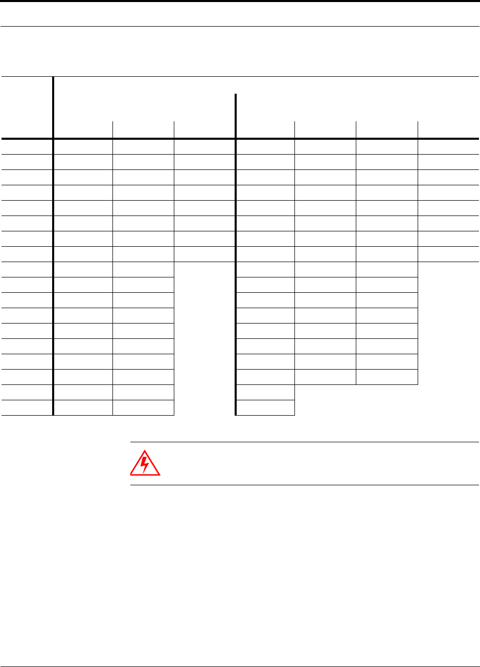
PN 8100-40 Help Hot Line (U.S. only): 1-800-530-9960 7-11
620004-0 Rev. E
Maximum Output Power per Carrier at RAU
WARNING: For 800 MHz Cellular or 1900 MHz PCS, do not exceed
the maximum composite input power of 126mW (+21 dBm) to the Main
Hub’s simplex ports, or 126µW (–9 dBm) to its duplex port at any time.
Table 7-8 800 MHz Cellular and 1900 MHz PCS Power per Carrier
No. of
Carriers
Recommended Maximum Output Power per Carrier at RAU (dBm)
800 MHz
(Lower Band)
1900 MHz
(Upper Band)
TDMA AMPS CDMA TDMA GSM EDGE CDMA
1 16.0 19.0 9.0 15.5 18.5 15.5 8.5
2 11.0 13.0 6.5 10.5 7.0 7.0 6.0
3 8.0 9.5 5.0 7.5 5.0 5.0 4.5
4 6.0 6.5 4.0 5.5 4.0 4.0 3.5
5 4.5 5.0 3.0 4.0 3.0 3.0 2.5
6 3.5 3.5 2.5 3.0 2.0 2.0 2.0
7 2.5 2.5 1.5 2.0 1.5 1.5 1.0
8 1.5 1.5 1.0 1.0 1.0 0.5 0.5
9 1.0 1.0 0.5 0.5 0.0
10 0.5 0.0 0.0 0.5 –0.5
11 0.0 0.0 –0.5 0.0 –1.0
12 –0.5 –0.5 –1.0 –0.5 –1.5
13 –0.5 –1.0 –1.0 –1.0 –1.5
14 –1.0 –1.5 –1.5 –1.0 –2.0
15 –1.5 –1.5 –2.0 –1.5 –2.5
16 –1.5 –2.0 –2.0 –2.0 –2.5
20 –2.5 –3.0 –3.0
30 –4.5 –5.0 –5.0
Note: These specifications are for downlink power at the RAU output (excluding antenna).
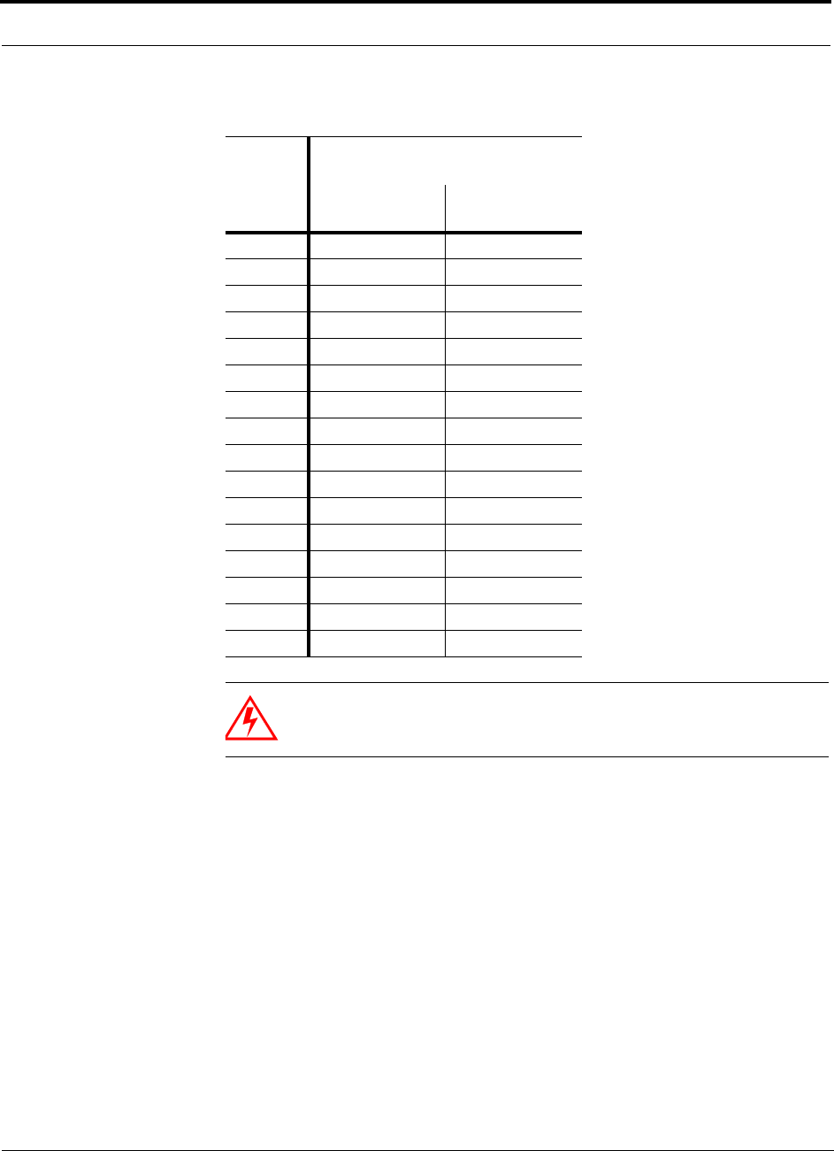
Designing an LGCell Solution
7-12 LGCell 4.0 Installation, Operation, and Reference Manual PN 8100-40
620004-0 Rev. E
WARNING: For 900 MHz GSM or EGSM and 1800 MHz GSM, do
not exceed the maximum composite input power of 126mW (+21 dBm)
to the Main Hub’s duplex and/or simplex ports at any time.
Table 7-9 900 MHz GSM or EGSM and 1800 MHz GSM Power per Carrier
No. of
Carriers
Maximum Output Power per
Carrier at RAU (dBm)
900 MHz
(Lower Band)
1800 MHz
(Upper Band)
18.0 8.0
23.5 4.5
31.5 2.5
40.5 1.0
5–0.5 0.0
6–1.5 –0.5
7–2.0 –1.0
8–2.5 –1.5
9–3.0 –2.0
10 –3.0 –2.5
11 –3.5 –2.5
12 –4.0 –3.0
13 –4.0 –3.5
14 –4.5 –3.5
15 –4.5 –4.0
16 –5.0 –4.0
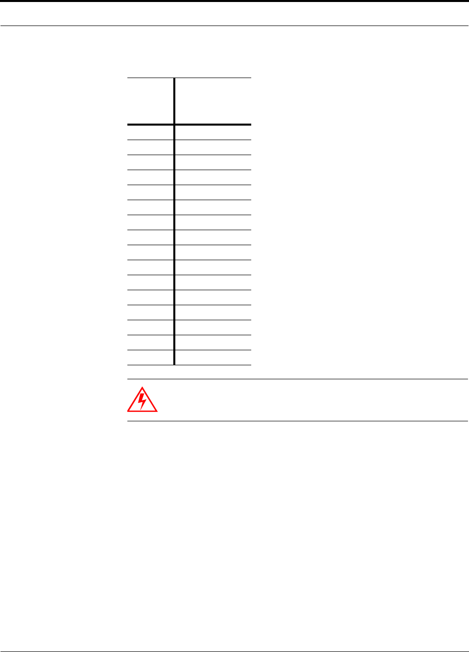
PN 8100-40 Help Hot Line (U.S. only): 1-800-530-9960 7-13
620004-0 Rev. E
Maximum Output Power per Carrier at RAU
WARNING: For 1800 MHz GSM, do not exceed the maximum com-
posite input power of 126mW (+21 dBm) to the Main Hub’s duplex
and/or simplex ports at any time.
Table 7-10 1800/1800 MHz GSM Power per Carrier
No. of
Carriers
Maximum
Output PPC
at RAU
(dBm)
18.0
22.5
30.5
4–0.5
5–1.5
6–2.5
7–3.0
8–3.5
9–3.5
10 –4.0
11 –4.5
12 –5.0
13 –5.5
14 –5.5
15 –6.0
16 –6.5

Designing an LGCell Solution
7-14 LGCell 4.0 Installation, Operation, and Reference Manual PN 8100-40
620004-0 Rev. E
Allowing for Future Capacity Growth
Sometimes an LGCell deployment initially is used to enhance coverage. Later that
same system may also need to provide increased capacity. Thus, the initial deploy-
ment might only transmit two carriers but need to transmit four carriers later. There
are two options for dealing with this scenario:
1. Design the initial coverage with a maximum power per carrier for four carriers.
2. Design the initial coverage for two carriers but leave Expansion Hub ports
unused. These ports can be used later if coverage holes are discovered once the
power per carrier is lowered to accommodate the two additional carriers.
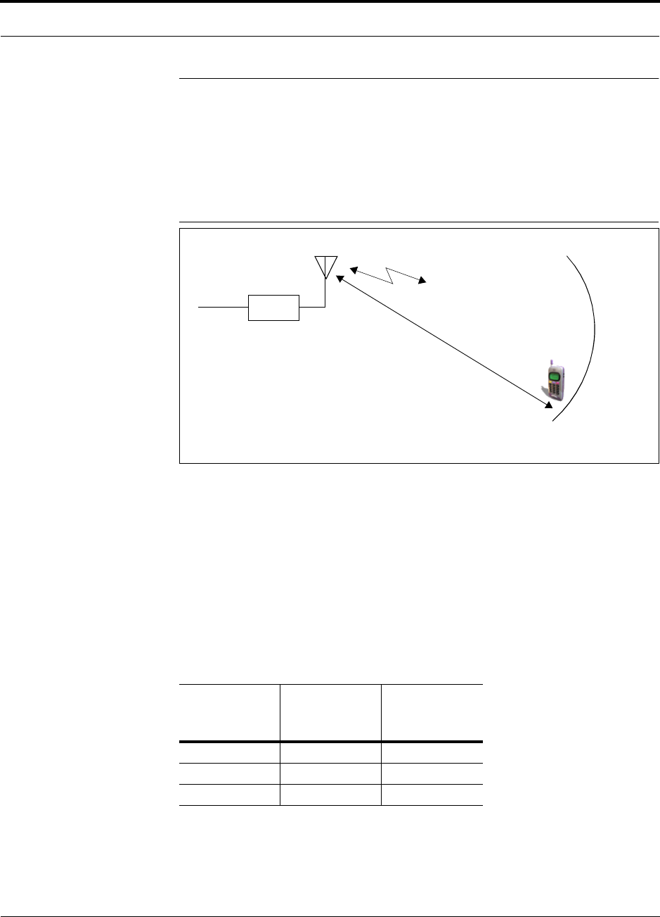
PN 8100-40 Help Hot Line (U.S. only): 1-800-530-9960 7-15
620004-0 Rev. E
Estimating RF Coverage
7.2 Estimating RF Coverage
The maximum power per carrier (based on the number and type of RF carriers that
are being transmitted) and the minimum acceptable received power at the wireless
device (i.e., RSSI, the design goal) establish the RF link budget, and consequently the
path loss between the antenna and the wireless device.
Figure 7-1 Determining Path Loss between the Antenna and the Wireless Device
(P + G) – RSSI = PL (1)
The path loss (PL) is the loss in decibels (dB) between the antenna and the wireless
device. The distance, d, from the antenna corresponding to this path loss can be calcu-
lated using the path loss equation in Section 7.2.1 or in Section 7.2.3.
The losses due to the coaxial cable that connects the RAU to the antenna are not
included in this equation because, typically, the cable is short and the losses are mod-
est. However, if further precision is desired, you can use the coaxial cable losses
listed in the following table.
Table 7-11 Coaxial Cable Losses
Length of
Cable
Loss at
800 MHz
(dB)
Loss at
1900 MHz
(dB)
0.9 m (3 ft) 0.6 0.8
1.8 m (6 ft) 1.0 1.5
3.0 m (10 ft) 1.5 2.3
RAU
P = power per d
Antenna and Gain (G)
RSSI = power at the
wireless device
carrier from the RAU
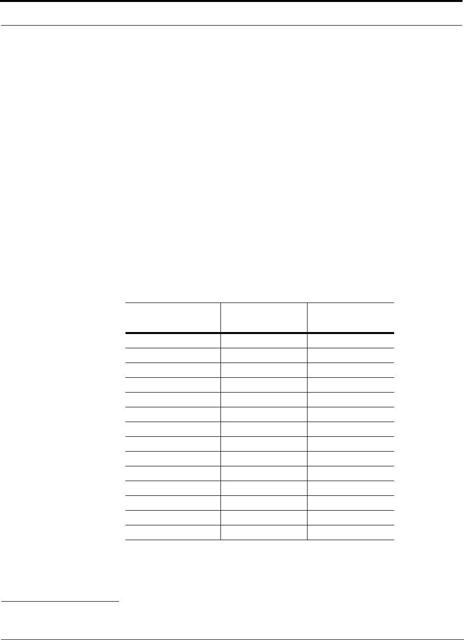
Designing an LGCell Solution
7-16 LGCell 4.0 Installation, Operation, and Reference Manual PN 8100-40
620004-0 Rev. E
7.2.1 Path Loss Equation
Indoor path loss obeys the distance power law* in equation (2):
PL = 20log(4πd0f/c) + 10nlog(d/d0) + Χs(2)
where:
• PL is the path loss at a distance, d, from the antenna (the distance between the
antenna that is connected to the RAU and the point where the RF signal
decreases to the minimum acceptable level at the wireless device).
•d
0 is taken as 1 meter of free-space.
• f is the operating frequency in hertz.
• c is the speed of light in a vacuum (3.0 × 10⁸ m/sec).
• n is the path loss exponent and depends on the building “clutter”.
•Χs is a normal random variable that depends on partition losses inside the build-
ing, and therefore, depends on the frequency of operation.
As a reference, the following table gives estimates of signal loss for some RF barriers.*
*Rappaport, Theodore S. Wireless Communications, Principles, and Practice. Prentice Hall PTR, 1996.
Table 7-12 Average Signal Loss of Common Building Materials
Partition Type
Loss (dB)
@ <2 GHz Frequency (MHz)
Metal wall 26 815
Aluminum siding 20 815
Foil insulation 4 815
Cubicle walls 1.4 900
Concrete block wall 13 1300
Concrete floor 10 1300
Sheetrock 1 to 2 1300
Light machinery 3 1300
General machinery 7 1300
Heavy machinery 11 1300
Equipment racks 7 1300
Assembly line 6 1300
Ceiling duct 5 1300
Metal stairs 5 1300
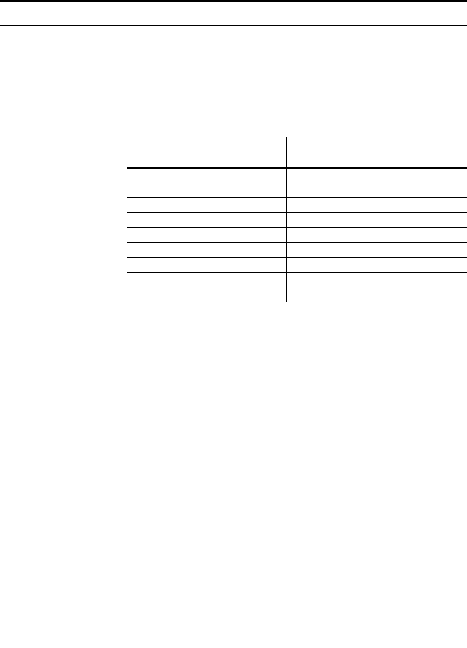
PN 8100-40 Help Hot Line (U.S. only): 1-800-530-9960 7-17
620004-0 Rev. E
Estimating RF Coverage
7.2.2 Path Loss Slope
Table 7-13 shows estimated path loss slope (PLS) for various environments that have
different “clutter” (i.e., objects that attenuate the RF signals, such as walls, partitions,
stairwells, equipment racks, etc.)
Table 7-13 Estimated Path Loss Slope for Different In-Building Environments
Facility
PLS for
800/900 MHz
PLS for
1800/1900 MHz
Manufacturing 35 32
Hospital 39.4 38.1
Airport 35 32
Retail 36.1 33.1
Warehouse 35 32
Parking Garage 33.7 30.1
Office: 80% cubicle/20% hard wall 36.1 33.1
Office: 50% cubicle/50% hard wall 37.6 34.8
Office: 20% cubicle/80% hard wall 39.4 38.1
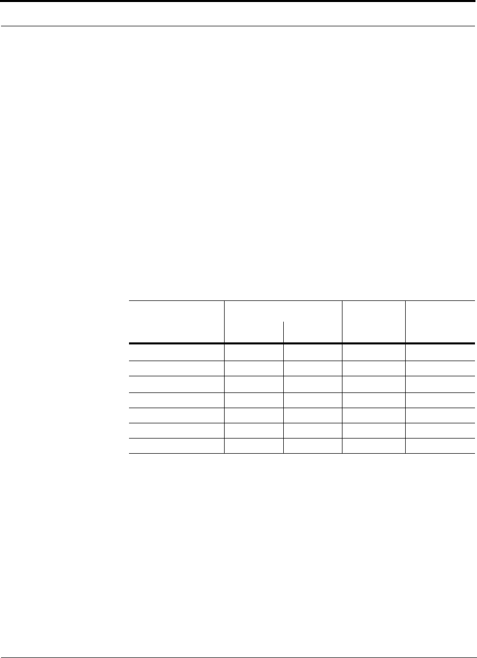
Designing an LGCell Solution
7-18 LGCell 4.0 Installation, Operation, and Reference Manual PN 8100-40
620004-0 Rev. E
7.2.3 Coverage Distance
Equations (1) and (2), on pages 7-15 and 7-16, respectively, can be used to estimate
the distance from the antenna to where the RF signal decreases to the minimum
acceptable level at the wireless device.
Equation (2) can be simplified to:
PL = 20log(4πf/c) + PLSlogD (3)
where PLS is chosen to account for partition losses. Because different frequencies
penetrate partitions with different losses, the value of PLS will vary depending on the
frequency.
For simplicity, Equation (3) can be used to estimate the coverage distance of an
antenna that is connected to an RAU, for a given path loss, frequency, and type of
in-building environment.
Table 7-14 gives the value of the first term of Equation (3) (i.e., (20log(4πf/c)) for
various frequency bands.
Table 7-14 Frequency Bands and the Value of the first Term in Equation (3)
Band (MHz) Mid-Band
Frequency
(MHz) 20log(4πf/c)Uplink Downlink
800 Cellulara
a. The 800 MHz CDMA/900 MHz GSM dual-band LGCell supports the following bands:
800 MHz CDMA
Downlink: 870 to 880 MHz
Uplink: 825 to 835 MHz
Bandwidth: 10 MHz
900 MHz GSM:
Downlink: 954 to 960 MHz
Uplink: 909 to 915 MHz
Bandwidth: 6 MHz
These bands are narrower than those for the 800 MHz Cellular and 900 MHz GSM single-band
LGCells. However, because the mid-band frequencies of the 800/900 dual-band LGCell bands are
almost identical to those for the single-band LGCells, the 20log(4πf/c) terms also are almost identical.
To simplify this table and those that follow, it is assumed that the first term in the equation (3) is the
same for the 800 MHz Cellular and the 800 MHz CDMA systems; likewise for the 900 MHz GSM sys-
tems.
824–849 869–894 859 31.1
800 iDEN 806–824 851–869 837.5 30.9
900 GSMa890–915 935–960 925 31.8
900 E-GSM 880–915 925–960 920 31.7
1800 DCS 1710–1785 1805–1880 1795 37.5
1800 CDMA (Korea) 1750–1780 1840–1870 1810 37.6
1900 PCS 1850–1910 1930–1990 1920 38.1
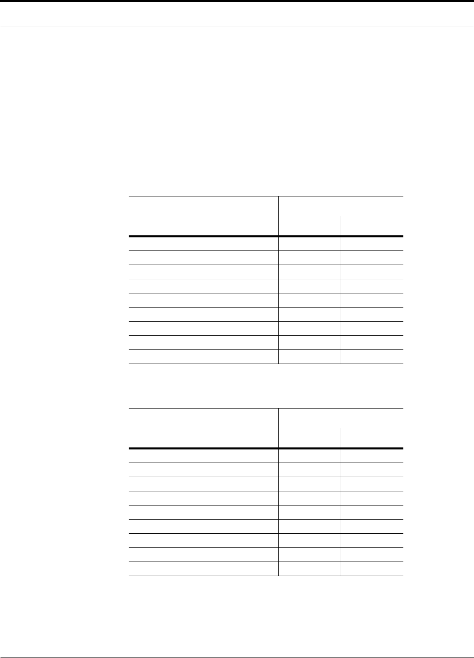
PN 8100-40 Help Hot Line (U.S. only): 1-800-530-9960 7-19
620004-0 Rev. E
Estimating RF Coverage
For reference, Tables 7-15 through 7-21 show the distance covered by an antenna for
various in-building environments. The following assumptions were made:
• Path loss Equation (3)
• 0 dBm output per carrier at the RAU output
• 3 dBi antenna gain
• RSSI = –85 dBm (typical for narrowband protocols, but not for spread-spec-
trum protocols)
Table 7-15 Approximate Radiated Distance from Antenna
for 800 MHz Cellular Applications
Facility
Distance from Antenna
Meters Feet
Manufacturing 42 138
Hospital 28 91
Airport 42 138
Retail 38 123
Warehouse 42 138
Parking Garage 49 160
Office: 80% cubicle/20% hard wall 38 123
Office: 50% cubicle/50% hard wall 33 107
Office: 20% cubicle/80% hard wall 28 91
Table 7-16 Approximate Radiated Distance from Antenna
for 800 MHz iDEN Applications
Facility
Distance from Antenna
Meters Feet
Manufacturing 43 140
Hospital 28 92
Airport 43 140
Retail 38 125
Warehouse 43 140
Parking Garage 49 162
Office: 80% cubicle/20% hard wall 38 125
Office: 50% cubicle/50% hard wall 33 108
Office: 20% cubicle/80% hard wall 28 92
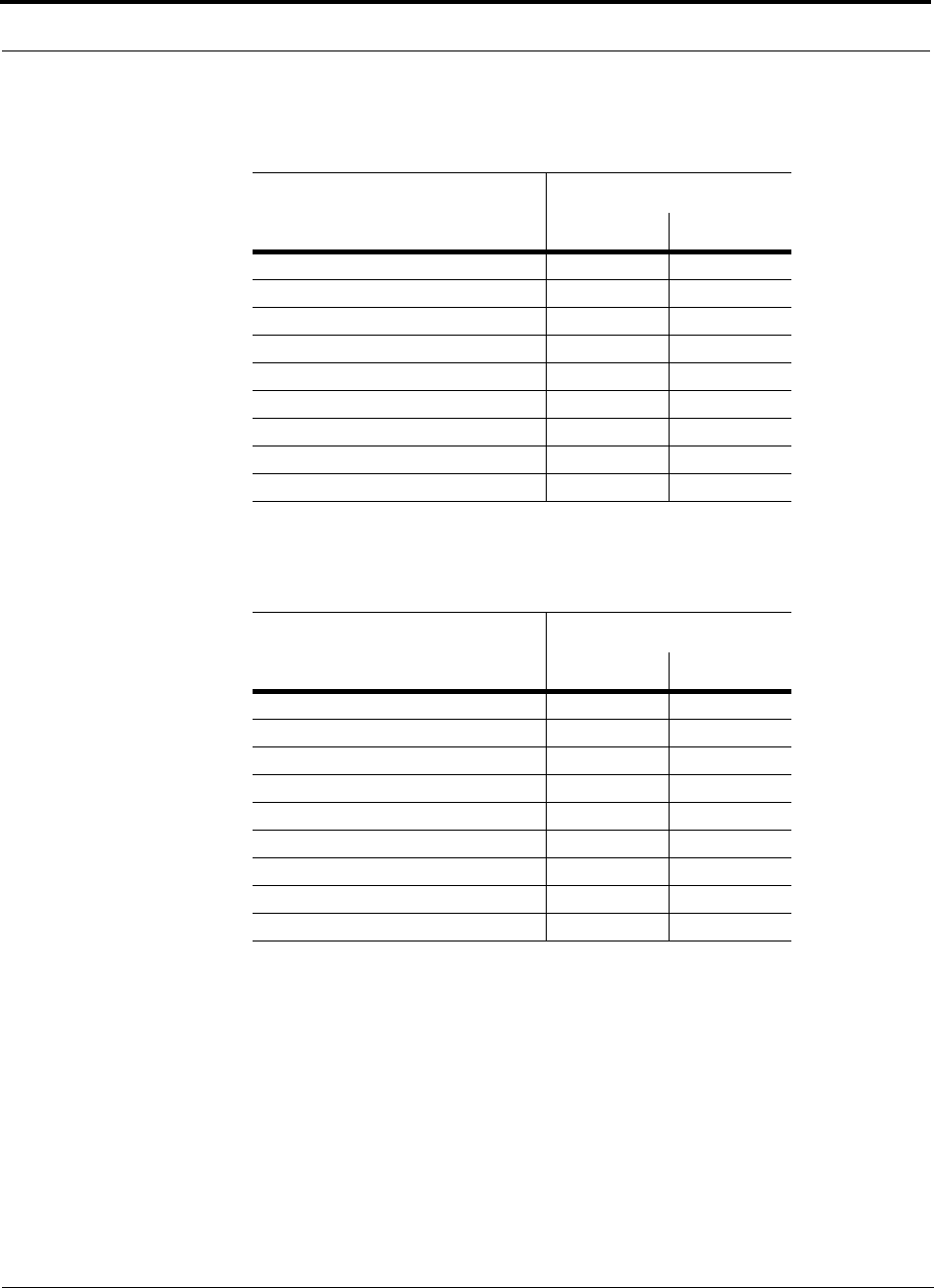
Designing an LGCell Solution
7-20 LGCell 4.0 Installation, Operation, and Reference Manual PN 8100-40
620004-0 Rev. E
Table 7-17 Approximate Radiated Distance from Antenna
for 900 MHz GSM Applications
Facility
Distance from Antenna
Meters Feet
Manufacturing 40 133
Hospital 27 88
Airport 40 133
Retail 36 118
Warehouse 40 133
Parking Garage 47 153
Office: 80% cubicle/20% hard wall 36 118
Office: 50% cubicle/50% hard wall 31 103
Office: 20% cubicle/80% hard wall 27 88
Table 7-18 Approximate Radiated Distance from Antenna
for 900 MHz EGSM Applications
Facility
Distance from Antenna
Meters Feet
Manufacturing 41 133
Hospital 27 88
Airport 41 133
Retail 36 119
Warehouse 41 133
Parking Garage 47 153
Office: 80% cubicle/20% hard wall 36 119
Office: 50% cubicle/50% hard wall 31 103
Office: 20% cubicle/80% hard wall 27 88
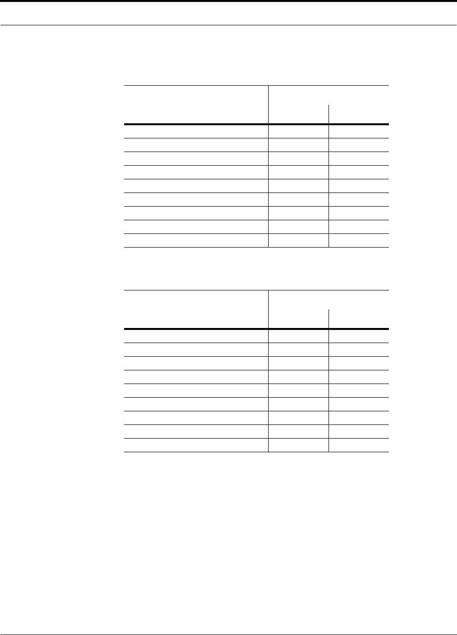
PN 8100-40 Help Hot Line (U.S. only): 1-800-530-9960 7-21
620004-0 Rev. E
Estimating RF Coverage
Table 7-19 Approximate Radiated Distance from Antenna
for 1800 MHz DCS Applications
Facility
Distance from Antenna
Meters Feet
Manufacturing 38 124
Hospital 21 69
Airport 38 124
Retail 33 110
Warehouse 38 124
Parking Garage 48 156
Office: 80% cubicle/20% hard wall 33 110
Office: 50% cubicle/50% hard wall 28 93
Office: 20% cubicle/80% hard wall 21 69
Table 7-20 Approximate Radiated Distance from Antenna
for 1800 MHz CDMA (Korea) Applications
Facility
Distance from Antenna
Meters Feet
Manufacturing 38 123
Hospital 21 69
Airport 38 123
Retail 33 109
Warehouse 38 123
Parking Garage 47 155
Office: 80% cubicle/20% hard wall 33 109
Office: 50% cubicle/50% hard wall 28 92
Office: 20% cubicle/80% hard wall 21 69
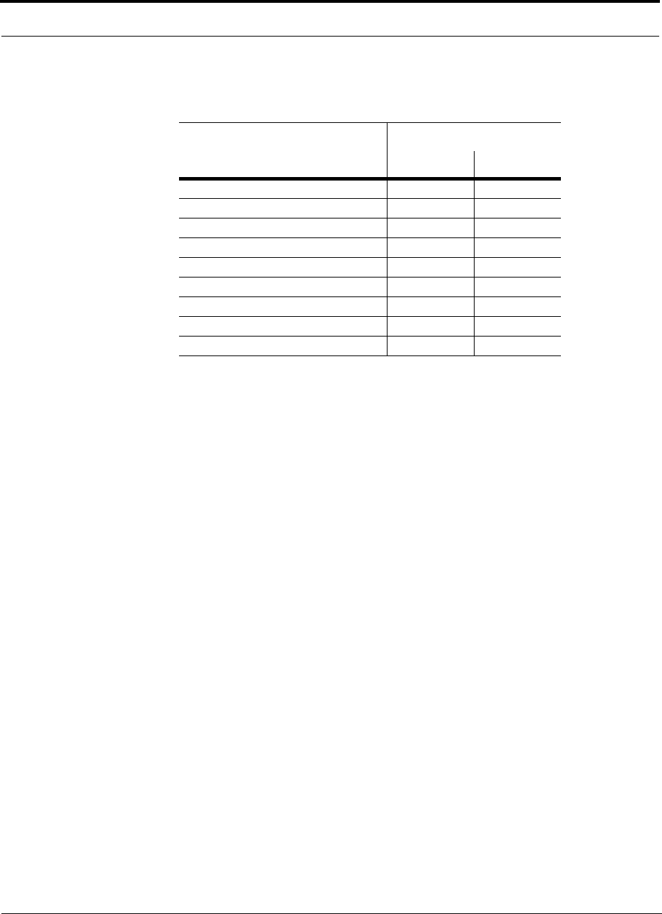
Designing an LGCell Solution
7-22 LGCell 4.0 Installation, Operation, and Reference Manual PN 8100-40
620004-0 Rev. E
Table 7-21 Approximate Radiated Distance from Antenna
for 1900 MHz PCS Applications
Facility
Distance from Antenna
Meters Feet
Manufacturing 36 119
Hospital 20 67
Airport 36 119
Retail 32 105
Warehouse 36 119
Parking Garage 45 149
Office: 80% cubicle/20% hard wall 32 105
Office: 50% cubicle/50% hard wall 27 89
Office: 20% cubicle/80% hard wall 20 67

PN 8100-40 Help Hot Line (U.S. only): 1-800-530-9960 7-23
620004-0 Rev. E
Estimating RF Coverage
7.2.4 Example Design Estimate
1. Design goals:
• Cellular (859 MHz = average of the lowest uplink and the highest downlink
frequency in 800 MHz Cellular band)
• TDMA provider
• 6 TDMA carriers in the system
• –85 dBm design goal (to 95% of the building) — the minimum received power
at the wireless device
• Base station with simplex RF connections
2. Power Per Carrier: The tables in Section 7.1, “Maximum Output Power per Car-
rier at RAU,” on page 7-3 provide maximum power per carrier information. The
800 MHz Cellular table (on page 7-4) indicates that the LGCell can support 6 car-
riers with a typical power per carrier of 4.5 dBm.
4.5 dBm per carrier would be the typical RF signal into the Main Hub’s FOR-
WARD (downlink) port. If the duplex port is used, you must take into account the
gain of the port (Table 7-22 on page 7-25) and adjust the input power accordingly.
For example, the duplex port on the 800 MHz LGCell provides 30 dB gain.
Therefore, the input power must be no greater than –25.5 dBm per carrier
(4.5 dBm – 30 dBm). Similarly, the PCS LGCell has a duplex port gain of 40 dB.
All other systems have 0 dB gain through all ports.
3. Building information:
• 8 floor building with 9,290 sq. meters (100,000 sq. ft.) per floor; total 74,322
sq. meters (800,000 sq. ft.)
• Walls are sheetrock construction; suspended ceiling tiles
• Antennas used will be omni-directional, ceiling mounted
• Standard office environment, 50% hard wall offices and 50% cubicles
4. Link Budget: In this example, a design goal of –85 dBm is used. Suppose 3 dBi
omni-directional antennas are used in the design. Then, the maximum RF propa-
gation loss should be no more than 92.5 dB (4.5 dBm + 3 dBi + 85 dBm) over
95% of the area being covered. It is important to note that a design goal such as
–85 dBm is usually derived taking into account multipath fading and log-normal
shadowing characteristics. Thus, this design goal will only be met “on average”
over 95% of the area being covered. At any given point, a fade may bring the sig-
nal level underneath the design goal.
Note that this method of calculating a link budget is only for the downlink path.
For information to calculate link budgets for both the downlink and uplink paths,
see Section 7.4 on page 7-28.
5. Path Loss Slope: For a rough estimate, Table 7-13, “Estimated Path Loss Slope for
Different In-Building Environments” on page 7-17, shows that a building with 50%
hard wall offices and 50% cubicles, at 859 MHz, has an approximate path loss slope
(PLS) of 37.6. Given the RF link budget of 92.3 dB, the distance of coverage from
each RAU will be 42 meters (138 ft). This corresponds to a coverage area of 5,641

Designing an LGCell Solution
7-24 LGCell 4.0 Installation, Operation, and Reference Manual PN 8100-40
620004-0 Rev. E
sq. meters (60,719 sq. ft.) per RAU (see Section 7.2.1 for details on path loss esti-
mation). For this case we assumed a circular radiation pattern, though the actual
area covered will depend upon the pattern of the antenna and the obstructions in the
facility.
If the area to be covered is essentially an unobstructed hallway with some cover-
age for the offices on either side of the hallway, a more aggressive design using a
lower PLS should be used.
6. Equipment Required: Since you know the building size, you can now estimate
the LGCell equipment quantities that will be needed. Before any RF levels are
tested in the building, you can estimate that 2 antennas per level will be needed.
a. 2 antennas per floor × 8 floors = 16 RAUs
b. 16 RAUs ÷ 4 (max 4 RAUs per Expansion Hub) = 4 Expansion Hubs
c. 4 Expansion Hubs ÷ 4 (max 4 Expansion Hubs per Main Hub) = 1 Main Hub
Check that the MMF and Cat-5 cable distances are as recommended. If the dis-
tances differ, use the tables in Section 7.3, “System Gain,” on page 7-25 to deter-
mine system gains or losses. The path loss may need to be recalculated to assure
adequate signal levels in the required coverage distance.
The above estimates assume that all cable length requirements are met. If Expansion
Hubs cannot be placed so that the RAUs are within the distance requirement, addi-
tional Expansion Hubs may need to be placed closer to the required RAUs locations.
An RF Site Survey and Building Evaluation is required to accurately establish the
LGCell equipment quantities required for the building. The site survey measures the
RF losses within the building to determine the actual PLS, which will be used in the
final path loss formula to determine the actual requirements of the LGCell.
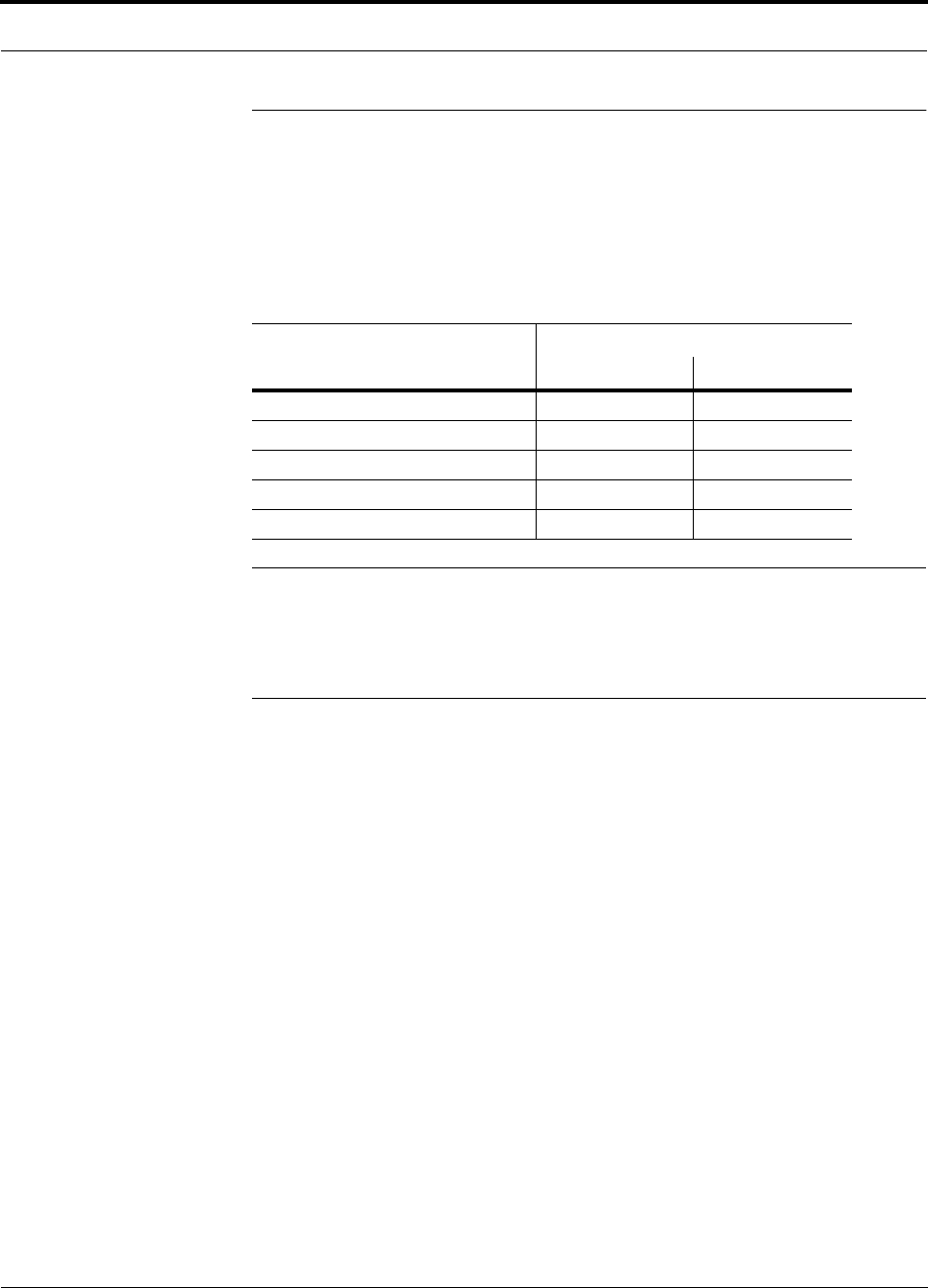
PN 8100-40 Help Hot Line (U.S. only): 1-800-530-9960 7-25
620004-0 Rev. E
System Gain
7.3 System Gain
The following table shows a summary of the system gain when 1 km (3300 ft) of
62.5µm/125µm multimode fiber is used. The optical loss of 1 km (3300 ft) of MMF
cable ranges from about 0.6 to 1.0 dB optical, depending on the type of cable
(i.e., riser zip-cord, loose tube, slotted core, etc.).
NOTE: The maximum input power to the Main Hub is equal to the maximum output
power of the RAU minus the system gain. For example, for a Cellular system with 6
TDMA carriers, the maximum output power is 4.5 dBm per carrier. If the duplex port
is used, the maximum input power to the Main Hub should be no greater than
–25.5 dBm per carrier.
Table 7-22 System Gain when using Duplex/Simplex Ports
LGCell Frequency and Format
System Gain (dB)
Duplex Port Simplex Ports
800 MHz Cellular 30 0
800 MHz iDEN 0 0
900 MHz GSM, EGSM 0 0
1800 MHz GSM 0 0
1900 MHz PCS 40 0
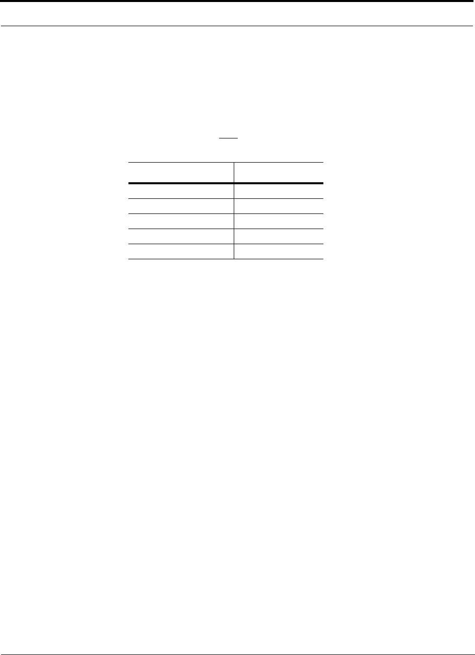
Designing an LGCell Solution
7-26 LGCell 4.0 Installation, Operation, and Reference Manual PN 8100-40
620004-0 Rev. E
7.3.1 System Gain (Loss) Relative to MMF Cable Length
If the length of MMF cable is less than 1 km (3300 ft), the system gain will increase.
If the cable length is between 1 km (3300 ft) and 2 km (6600 ft), the system gain will
decrease as the cable length increases. Use the following formula for determining the
nominal gain (or loss) of the LGCell. The length of the MMF cable is denoted by L:
The optical power budget between the Main Hub and Expansion Hub, both downlink
and uplink, is 3 dB optical. If fiber distribution panels are used, confirm that the total
optical loss of fiber cable, from the Main Hub through distribution panels and patch
cords to the Expansion Hub, does not exceed 3 dB optical.
MMF Cable Length System Gain (dB)
1 m / 3.3 ft +3
500 m / 1650 ft +1.5
1000 m / 3300 ft 0
1500 m / 4950 ft –1.5
2000 m / 6600 ft –3
MMF cable length greater than 2 km (6600 ft) is not rec-
ommended.
gain (dB) = 3*(1 – )
L
1000