ADC Telecommunications DAS819A-4 In Building Repeater - Remote Access Unit User Manual Part 2 Revised
ADC Telecommunications Inc. In Building Repeater - Remote Access Unit Users Manual Part 2 Revised
Contents
- 1. Users Manual Part 1
- 2. Users Manual Part 2 Revised
Users Manual Part 2 Revised
PN 8100-40 Help Hot Line (U.S. only): 1-800-530-9960 7-27
620004-0 Rev. E
System Gain
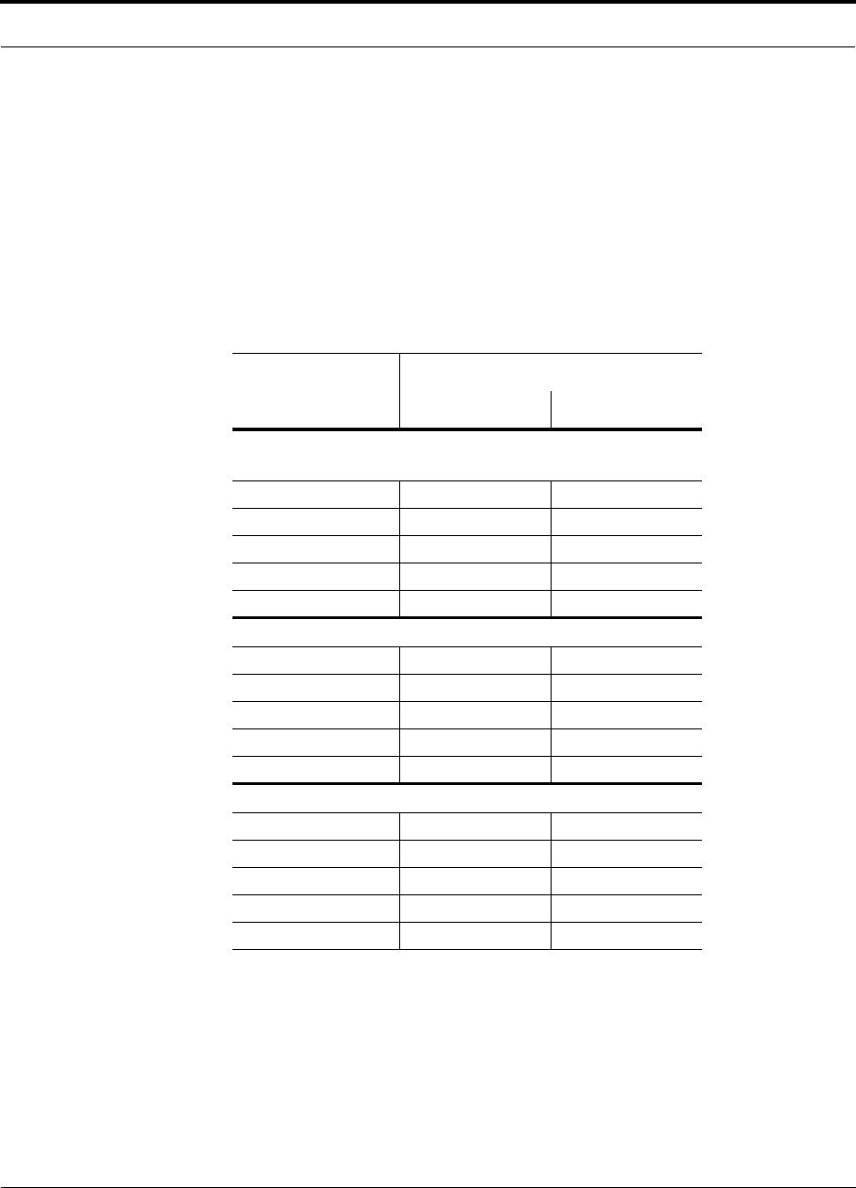
7.3.2 System Gain (Loss) Relative to UTP/STP Cable Length
The recommended minimum length of UTP/STP cable is 20 meters (66 ft) and the
recommended maximum length is 50 meters (165 ft). If the UTP/STP cable is less
than 20 meters (66 ft), system performance may not meet specifications; the absolute
minimum cable length is 10 meters (33 ft). If the UTP/STP cable is longer than 50
meters (165 ft), the gain of the system will decrease, as shown in Table 7-23.
Only shielded Cat-5 cable (STP) should be used when running parallel Cat-5 cables
for an LGCell system.
Table 7-23 System Gain (Loss) Relative to UTP/STP Cable Length
UTP/STP Cable
Length
Typical change in system gain (dB)
Downlink Uplink
800 MHz Cellular; 800 MHz iDEN; and 900 MHz GSM
and EGSM
60 m / 198 ft –0.7 –0.3
70 m / 231 ft –2.9 –2.1
80 m / 264 ft –5.1 –3.9
90 m / 297 ft –7.3 –5.7
100 m / 330 ft –9.5 –7.5
1800 MHz DCS (GSM)
60 m / 198 ft –1.2 –0.3
70 m / 231 ft –3.9 –2.1
80 m / 264 ft –6.6 –3.9
90 m / 297 ft –9.3 –5.7
100 m / 330 ft –12 –7.5
1900 MHz PCS
60 m / 198 ft –1.0 –0.3
70 m / 231 ft –3.5 –2.1
80 m / 264 ft –6.0 –3.9
90 m / 297 ft –8.5 –5.7
100 m / 330 ft –11 –7.5
Designing an LGCell Solution
7-28 LGCell 4.0 Installation, Operation, and Reference Manual PN 8100-40
620004-0 Rev. E
7.4 Link Budget Analysis
A link budget is a methodical way to account for the gains and losses in an RF system
so that the quality of coverage can be predicted. The end result can often be stated as
a “design goal” in which the coverage is determined by the maximum distance from
each RAU before the signal strength falls beneath that goal.
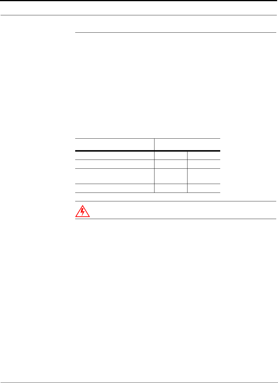
One key feature of the link budget is the maximum power per carrier discussed in
Section 7.1. While the maximum power per carrier is important as far as emissions
and signal quality requirements are concerned, it is critical that the maximum signal
into the Main Hub never exceed +21 dBm (126mW) minus system gain. Composite
power levels above this limit will cause damage to the Main Hub.
WARNING: Exceeding the maximum input power could cause perma-
nent damage to the Main Hub.
Table 7-24 LGCell Maximum Input Power
LGCell System Maximum Input Power
Simplex Ports (all LGCells) +21 dBm 126mW
Duplex Ports (Cellular) –9 dBm 126µW
Duplex Ports (iDEN, GSM,
EGSM, DCS, CDMA-Korea)
+21 dBm 126mW
Duplex Ports (1900 MHz PCS) –19 dBm 12.6µW

PN 8100-40 Help Hot Line (U.S. only): 1-800-530-9960 7-29
620004-0 Rev. E
Link Budget Analysis
7.4.1 Elements of a Link Budget for Narrowband Standards
The link budget represents a typical calculation that might be used to determine how
much path loss can be afforded in an LGCell design. This link budget analyzes both
the downlink and uplink paths. For most configurations, the downlink requires lower
path loss and is therefore the limiting factor in the system design. It is for this reason
that a predetermined “design goal” for the downlink is sufficient to predict coverage
distance.
The link budget is organized in a simple manner: the transmitted power is calculated,
the airlink losses due to fading and body loss are summed, and the receiver sensitivity
(minimum level a signal can be received for acceptable call quality) is calculated. The
maximum allowable path loss (in dB) is the difference between the transmitted
power, less the airlink losses, and the receiver sensitivity. From the path loss, the
maximum coverage distance can be estimated using the path loss formula presented
in Section 7.2.1.
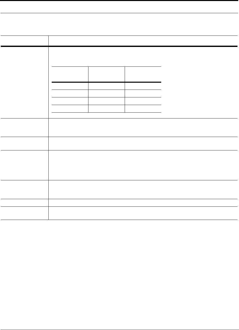
Table 7-25 provides link budget considerations for narrowband systems.
Table 7-25 Link Budget Considerations for Narrowband Systems
Consideration Description
BTS Transmit Power The power per carrier transmitted from the base station output
Attenuation between
BTS and LGCell
This includes all losses: cable, attenuator, splitter/combiner, and so forth.
On the downlink, attenuation must be chosen so that the maximum power per carrier going into the
Main Hub does not exceed the levels given in Section 7.1.
On the uplink, attenuation is chosen to keep the maximum uplink signal and noise level low enough
to prevent base station alarms but small enough not to cause degradation in the system sensitivity.
If the LGCell noise figure minus the attenuation is at least 10 dB higher than the BTS noise figure,
the system noise figure will be approximately that of the LGCell alone. See Section 7.5 for ways to
independently set the uplink and downlink attenuations between the base station and the LGCell.
LGCell Gain This is the system gain (see Table 7-22 on page 7-25)
Antenna Gain The radiated output power includes antenna gain. For example, if you use a 3 dBi antenna at the
RAU that is transmitting 0 dBm per carrier, the effective radiated power (relative to an isotropic
radiator) is 3 dBm per carrier.
BTS Noise Figure This is the effective noise floor of the base station input (usually base station sensitivity is this effec-
tive noise floor plus a certain C/I ratio).
LGCell Noise Figure This is the LGCell’s uplink noise figure, which varies depending on the number of Expansion Hubs
and RAUs, and the frequency band. The LGCell uplink noise figure is specified for a 1-1-4 configu-
ration. Thus, the noise figure for an LGCell (or multiple LGCells whose uplink ports are power com-
bined) will be NF(1-1-4) + 10*log(# of Expansion Hubs). This represents an upper-bound because
the noise figure is lower if any of the Expansion Hub’s RAU ports are not used.
Designing an LGCell Solution
7-30 LGCell 4.0 Installation, Operation, and Reference Manual PN 8100-40
620004-0 Rev. E
Thermal Noise This is the noise level in the signal bandwidth (BW).
Thermal noise power = –174 dBm/Hz + 10Log(BW).
Required C/I ratio For each wireless standard a certain C/I (carrier to interference) ratio is needed to obtain acceptable
demodulation performance. For narrowband systems, (TDMA, GSM, EDGE, iDEN, AMPS) this
level varies from about 9 dB to 20 dB.
Mobile Transmit
Power
The maximum power the mobile can transmit (power transmitted at highest power level setting).
Multipath Fade
Margin
This margin allows for a certain level of fading due to multipath interference. Inside buildings there
is often one or more fairly strong signals and many weaker signals arriving from reflections and dif-
fraction. Signals arriving from multiple paths add constructively or destructively. This margin
accounts for the possibility of destructive multipath interference. In RF site surveys this margin will
not appear because it will be averaged out over power level samples taken over many locations.
Log-normal Fade
Margin
This margin adds an allowance for RF shadowing due to objects obstructing the direct path between
the mobile equipment and the RAU. In RF site surveys, this shadowing will not appear because it
will be averaged out over power level samples taken over many locations.
Body Loss This accounts for RF attenuation caused by the user’s head and body.
Minimum Received
Signal Level
This is also referred to as the “design goal”. The link budget says that you can achieve adequate cov-
erage if the signal level is, on average, above this level over 95% of the area covered, for example.
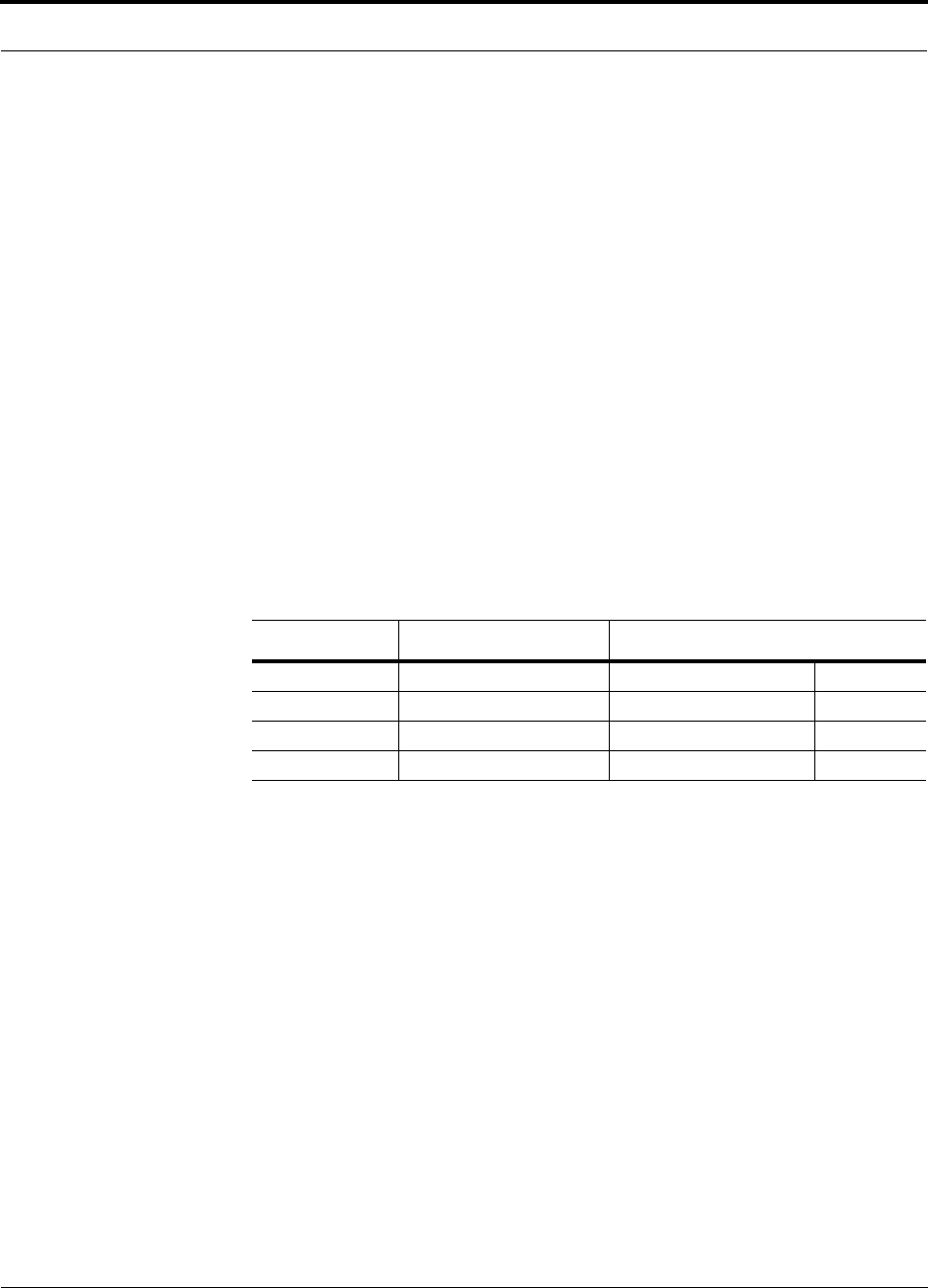
Table 7-25 Link Budget Considerations for Narrowband Systems (continued)
Consideration Description
Protocol
Signal
Bandwidth
Thermal
Noise
TDMA 30 kHz –129 dBm
CDMA 1.25 MHz –113 dBm
GSM 200 kHz –121 dBm
iDEN 25 kHz –130 dBm

PN 8100-40 Help Hot Line (U.S. only): 1-800-530-9960 7-31
620004-0 Rev. E
Link Budget Analysis
7.4.2 Narrowband Link Budget Analysis for a Microcell Application
Narrowband Link Budget Analysis: Downlink
• c = a + b
• f = c + d + e
• j = g + h + i
• n = k + l + m
• k: in this example, k represents the thermal noise for a TDMA signal, which
has a bandwidth of 30 kHz
• p = f – j – n
Line Downlink
Transmitter
a. BTS transmit power per carrier (dBm) 33
b. Attenuation between BTS and LGCell (dB) –30
c. Power into LGCell (dBm) 3
d. LGCell gain (dB) 0
e. Antenna gain (dBi) 3
f. Radiated power per carrier (dBm) 6
Airlink
g. Multipath fade margin (dB) 6
h. Log-normal fade margin with 8 dB std. deviation, edge reliability 90%
(dB)
10
i. Body loss (dB) 3
j. Airlink losses (not including facility path loss) 19
Receiver
k. Thermal noise (dBm/30 kHz) –129
l. Mobile noise figure (dB) 7
m. Required C/I ratio (dB) 12
n. Minimum received signal (dBm) –110
p. Maximum path loss (dB) 97

Designing an LGCell Solution
7-32 LGCell 4.0 Installation, Operation, and Reference Manual PN 8100-40
620004-0 Rev. E
Narrowband Link Budget Analysis: Uplink
• e: enter the noise figure and gain of each system component (a, b, c, and d) into
the standard cascaded noise figure formula
• i = f + e + g – h
• m = j + k + l
• p = n – m – i
Line Uplink
Receiver
a. BTS noise figure (dB) 4
b. Attenuation between BTS and LGCell (dB) –10
c. LGCell gain (dB) 0
d. LGCell noise figure (dB) 27
e. System noise figure (dB) 27.2
f. Thermal noise (dBm/30 kHz) –129
g. Required C/I ratio (dB) 12
h. Antenna gain (dBi) 3
i. Receive sensitivity (dBm) –92.8
Airlink
j. Multipath fade margin (dB) 6
k. Log-normal fade margin with 8 dB std. deviation, edge reliability 90%
(dB)
10
l. Body loss (dB) 3
m. Airlink losses (not including facility path loss) 19
Transmitter
n. Mobile transmit power (dBm) 28
p. Maximum path loss (dB) 101.8
Fsys = F1 + + + ....
F2 – 1
G1
F3 – 1
G1G2
where
F = 10
(See Rappaport, Theodore S. Wireless Communications, Principles, and Practice. Prentice Hall PTR, 1996.)
(Noise Figure/10)
G = 10(Gain/10)
PN 8100-40 Help Hot Line (U.S. only): 1-800-530-9960 7-33
620004-0 Rev. E
Link Budget Analysis
7.4.3 Elements of a Link Budget for CDMA Standards
A CDMA link budget is slightly more complicated because the spread spectrum
nature of CDMA must be considered. Unlike narrowband standards such as TDMA
and GSM, CDMA signals are spread over a relatively wide frequency band. Upon
reception, the CDMA signal is de-spread. In the de-spreading process the power in
the received signal becomes concentrated into a narrow band, whereas the noise level
remains unchanged. Hence, the signal-to-noise ratio of the de-spread signal is higher
than that of the CDMA signal before de-spreading. This increase is called processing
gain. For IS-95 and J-STD-008, the processing gain is 21 dB or 19 dB depending on
the user data rate (9.6 Kbps for rate set 1 and 14.4 Kbps for rate set 2, respectively).
Because of the processing gain, a CDMA signal (comprising one Walsh code channel
within the composite CDMA signal) can be received at a lower level than that
required for narrowband signals. A reasonable level is –95 dBm, which results in
about –85 dBm composite as shown below.
An important issue to keep in mind is that the downlink CDMA signal is composed of
many orthogonal channels: pilot, paging, sync, and traffic. The composite power
level is the sum of the powers from the individual channels. An example is given in
the following table.
This table assumes that there are 15 active traffic channels operating with 50% voice
activity (so that the total power adds up to 100%). Notice that the pilot and sync chan-
nels together contribute about 25% of the power. When measuring the power in a
CDMA signal you must be aware that if only the pilot and sync channels are active,
the power level will be about 6 to 7 dB lower than the maximum power level you can
expect when all voice channels are active. The implication is that if only the pilot and
sync channels are active, and the maximum power per carrier table says that you
should not exceed 10 dBm for a CDMA signal, for example, then you should set the
attenuation between the base station and the LGCell so that the Main Hub receives
3 dBm (assuming 0 dB system gain).
An additional consideration for CDMA systems is that the uplink and downlink paths
should be gain and noise balanced. This is required for proper operation of soft-hand-
off to the outdoor network as well as preventing excess interference that is caused by
mobiles on the indoor system transmitting at power levels that are not coordinated
with the outdoor mobiles. This balance is achieved if the power level transmitted by
Table 7-26 Distribution of Power within a CDMA Signal
Channel Walsh Code Number Relative Power Level
Pilot 0 20% –7.0 dB
Sync 32 5% –13.3 dB
Primary Paging 1 19% –7.3 dB
Traffic 8–31, 33–63 9% (per traffic channel) –10.3 dB

Designing an LGCell Solution
7-34 LGCell 4.0 Installation, Operation, and Reference Manual PN 8100-40
620004-0 Rev. E
the mobiles under close-loop power control is similar to the power level transmitted
under open-loop power control. The open-loop power control equation is
PTX + PRX = –73 dBm (for Cellular, IS-95)
PTX + PRX = –76 dBm (for PCS, J-STD-008)
where PTX is the mobile’s transmitted power and PRX is the power received by the
mobile.
The power level transmitted under closed-loop power control is adjusted by the base
station to achieve a certain Eb/N0 (explained in Table 7-27 on page 7-34). The differ-
ence between these power levels, ∆P
, can be estimated by comparing the power radi-
ated from the RAU, Pdownink, to the minimum received signal, Puplink, at the RAU:
∆P = Pdownink + Puplink + 73 dBm (for Cellular)
∆P = Pdownink + Puplink + 76 dBm (for PCS)
It’s a good idea to keep –12 dB < ∆P < 12 dB.
Table 7-27 provides link budget considerations for CDMA systems.
Table 7-27 Additional Link Budget Considerations for CDMA Systems
Consideration Description
Multipath Fade
Margin
The multipath fade margin can be reduced (by at least 3 dB) by using different lengths of optical fiber (this
is called “delay diversity”). The delay over fiber is approximately 5µS/km. If the difference in fiber
lengths to Expansion Hubs with overlapping coverage areas produces at least 1 chip (0.8µS) delay of one
path relative to the other, then the multipaths’ signals can be resolved and processed independently by the
base station’s rake receiver. A CDMA signal traveling through 163 meters of MMF cable will be delayed
by approximately one chip.
Power per car-
rier, downlink
This depends on how many channels are active. For example, the signal will be about 7 dB lower if only
the pilot, sync, and paging channels are active compared to a fully-loaded CDMA signal. Furthermore, in
the CDMA forward link, voice channels are turned off when the user is not speaking. On average this is
assumed to be about 50% of the time. So, in the spreadsheet, both the power per Walsh code channel (rep-
resenting how much signal a mobile will receive on the Walsh code that it is de-spreading) and the total
power are used.
The channel power is needed to determine the maximum path loss, and the total power is needed to deter-
mine how hard the LGCell is being driven.
The total power for a fully-loaded CDMA signal is given by (approximately):
total power = voice channel power + 13 dB + 10log10 (50%)
= voice channel power + 10 dB
Information Rate This is simply
10log10(9.6 Kbps) = 40 dB for rate set 1
10log10(14.4 Kbps) = 42 dB for rate set 2

PN 8100-40 Help Hot Line (U.S. only): 1-800-530-9960 7-35
620004-0 Rev. E
Link Budget Analysis
Other CDMA Issues
• Never combine multiple sectors (more than one CDMA signal at the same fre-
quency) into an LGCell. The combined CDMA signals will interfere with each
other.
• Try to minimize overlap between in-building coverage areas that utilize different
sectors, as well as in-building coverage and outdoor coverage areas. This is impor-
tant because any area in which more than one dominant pilot signal (at the same
frequency) is measured by the mobile will result in soft-handoff. Soft-handoff
decreases the overall network capacity by allocating multiple channel resources to
a single mobile phone.
Process Gain The process of de-spreading the desired signal boosts that signal relative to the noise and interference.
This gain needs to be included in the link budget. In the following formulas, PG = process gain:
PG = 10log10(1.25 MHz / 9.6 Kbps) = 21 dB rate set 1
PG = 10log10(1.25 MHz / 14.4 Kbps) = 19 dB rate set 2
Note that the process gain can also be expressed as 10log10 (CDMA bandwidth) minus the information
rate.
Eb/No This is the energy-per-bit divided by the received noise and interference. It’s the CDMA equivalent of sig-
nal-to-noise ratio (SNR). This figure depends on the mobile’s receiver and the multipath environment. For
example, the multipath delays inside a building are usually too small for a rake receiver in the mobile (or
base station) to resolve and coherently combine multipath components. However, if artificial delay can be
introduced by, for instance, using different lengths of cable, then the required Eb/No will be lower and the
multipath fade margin in the link budget can be reduced in some cases.
If the receiver noise figure is NF (dB), then the receive sensitivity (dBm) is given by:
Psensitivity = NF + Eb/No + thermal noise in a 1.25 MHz band – PG
= NF + Eb/No – 113 (dBm/1.25 MHz) – PG
Noise Rise On the uplink, the noise floor is determined not only by the LGCell, but also by the number of mobiles
that are transmitting. This is because when the base station attempts to de-spread a particular mobile’s sig-
nal, all other mobile signals appear to be noise. Because the noise floor rises as more mobiles try to com-
municate with a base station, the more mobiles there are, the more power they have to transmit. Hence, the
noise floor rises rapidly:
noise rise = 10log10(1 / (1 – loading))
where loading is the number of users as a percentage of the theoretical maximum number of users.
Typically, a base station is set to limit the loading to 75%. This noise ratio must be included in the link
budget as a worst-case condition for uplink sensitivity. If there are less users than 75% of the maximum,
then the uplink coverage will be better than predicted.
Hand-off Gain CDMA supports soft hand-off, a process by which the mobile communicates simultaneously with more
than one base station or more than one sector of a base station. Soft hand-off provides improved receive
sensitivity because there are two or more receivers or transmitters involved. A line for hand-off gain is
included in the CDMA link budgets worksheet although the gain is set to 0 dB because the in-building
system will probably be designed to limit soft-handoff.
Table 7-27 Additional Link Budget Considerations for CDMA Systems
Consideration Description

Designing an LGCell Solution
7-36 LGCell 4.0 Installation, Operation, and Reference Manual PN 8100-40
620004-0 Rev. E
7.4.4 Spread Spectrum Link Budget Analysis for a Microcell
Application
Spread Spectrum Link Budget Analysis: Downlink
Line Downlink
Transmitter
a. BTS transmit power per carrier (dBm) 30.0
b. Voice activity factor 50%
c. Maximum composite power (dBm) 40.0
d. Attenuation between BTS and LGCell (dB) –30
e. Power per carrier into LGCell (dBm) 3.0
f. Composite power into LGCell (dBm) 10.0
g. LGCell gain (dB) 0.0
h. Antenna gain (dBi) 3.0
i. Radiated power per carrier (dBm) 3.0
j. Total radiated power (dBm) 13.0
Airlink
k. Handoff gain (dB) 7.0
l. Multipath fade margin (dB) 6.0
m. Log-normal fade margin with 8 dB std. deviation, edge reliability
90% (dB)
10.0
n. Additional loss (dB) 0.0
o. Body loss (dB) 3.0
p. Airlink losses (not including facility path loss) 19.0
Receiver
q. Mobile noise figure (dB) 7.0
r. Thermal noise (dBm/Hz) –174.0
s. Receiver interference density (dBm/Hz) –167.0
t. Information ratio (dB/Hz) 41.6
u. Required Eb/(No+lo) 7.0
v. Receive Sensitivity (dBm) –118.4
w. Minimum received signal (dBm) –99.4
x. Maximum path loss (dB) 102.4
y. Difference between open- and closed-loop transmitter power (dB) –2.0

PN 8100-40 Help Hot Line (U.S. only): 1-800-530-9960 7-37
620004-0 Rev. E
Link Budget Analysis
• b and c: see notes in Table 7-27 regarding power per carrier, downlink
• e = a + d
• f = c + d
• i = e + g + h
• j = f + g + h
• p = –k + l + m + n + o
• s = q + r
• v = s + t + u
• w = p + v
• x = j – w
• y = j (downlink) + m (uplink) + P
where
P = Ptx + Prx = –73 dB for Cellular
–76 dB for PCS

Designing an LGCell Solution
7-38 LGCell 4.0 Installation, Operation, and Reference Manual PN 8100-40
620004-0 Rev. E
Spread Spectrum Link Budget Analysis: Uplink
Line Uplink
Receiver
a. BTS noise figure (dB) 3.0
b. Attenuation between BTS and LGCell (dB) –30.0
c. LGCell gain (dB) 0.0
d. LGCell noise figure (dB) 23.0
e. System noise figure (dB) 33.4
f. Thermal noise (dBm/Hz) –174.0
g. Noise rise 75% loading (dB) 6.0
h. Receiver interference density (dBm/Hz) –134.6
i. Information rate (dB/Hz) 41.6
j. Required Eb/(No+lo) 5.0
k. Handoff gain (dB) 0.0
l. Antenna gain (dBi) 3.0
m. Minimum received signal (dBm) –91.0
Airlink
n. Multipath fade margin (dB) 6.0
o. Log-normal fade margin with 8 dB std. deviation, edge reliability
90% (dB)
10.0
p. Additional loss (dB) 0.0
q. Body loss (dB) 3.0
r. Airlink losses (not including facility path loss) 19.0
Transmitter
s. Mobile transmit power (dBm) 28.0
t. Effective transmitted power (dBm) 9.0
u. Maximum path loss (dB) 100.0

PN 8100-40 Help Hot Line (U.S. only): 1-800-530-9960 7-39
620004-0 Rev. E
Link Budget Analysis
• e: enter the noise figure and gain of each system component (a, b, c, and d) into
the standard cascaded noise figure formula
• h = e + f + g
• m = h + i + j –k – l
• r = n + o + p + q
• t = s – r
• u = t – m
Fsys = F1 + + + ....
F2 – 1
G1
F3 – 1
G1G2
where
F = 10
(See Rappaport, Theodore S. Wireless Communications, Principles, and Practice. Prentice Hall PTR, 1996.)
(Noise Figure/10)
G = 10(Gain/10)

Designing an LGCell Solution
7-40 LGCell 4.0 Installation, Operation, and Reference Manual PN 8100-40
620004-0 Rev. E
7.4.5 Considerations for Re-Radiation (over-the-air) Systems
The LGCell can be used to extend the coverage of the outdoor network by connecting
to a roof-top donor antenna that is pointed toward an outdoor base station. Additional
considerations for such an application of the LGCell are:
• Sizing the gain and output power requirements for a bi-directional amplifier
(repeater).
• Ensuring that noise radiated on the uplink from the in-building system does not
cause the outdoor base station to become desensitized to wireless handsets in the
outdoor network.
• Filtering out signals that lie in adjacent frequency bands. For instance, if you are
providing coverage for Cellular B-band operation it may be necessary to filter out
the A, A’ and A” bands which may contain strong signals from other outdoor base
stations.
Further information on these issues can be found in LGC Wireless’ application notes
for re-radiation applications.
PN 8100-40 Help Hot Line (U.S. only): 1-800-530-9960 7-41
620004-0 Rev. E
Connecting a Main Hub to a Base Station
7.5 Connecting a Main Hub to a Base Station
The first consideration when connecting LGCell Main Hubs to a base station is to
ensure there is an equal amount of loss through cables, combiners, etc. from the base
station to the Main Hubs. For this example, assume that the base station will have
simplex connections, one uplink and one downlink. Each of these connections will
need to be divided to equilibrate power for each Main Hub. For example, two Main
Hubs will require a 2×1 combiner/divider; four Main Hubs will require a 4×1 com-
biner/divider; and so on.
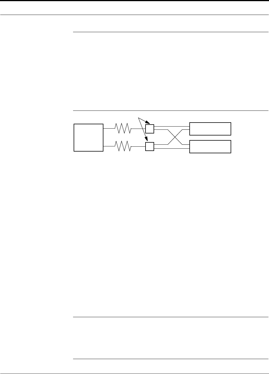
Figure 7-2 Connecting LGCell Main Hubs to a Simplex Base Station
When connecting an LGCell to a base station, also consider the following:
1. The downlink power from the base station must be attenuated enough so that the
power radiated by the RAU does not exceed the maximum power per carrier listed
in Section 7.1, “Maximum Output Power per Carrier at RAU,” on page 7-3.
2. The uplink attenuation should be small enough that the sensitivity of the overall
system is limited by the LGCell, not by the attenuator. However, some base sta-
tions are adversely affected by received signals that are above –50 dBm, for
example. It is therefore helpful to attenuate the uplink in order to retain the maxi-
mum number of received signals.
If, in an area covered by an LGCell, a mobile phone indicates good signal strength
but consistently has difficulty completing calls, it is possible that the attenuation
between the LGCell and base station needs to be adjusted. In other words, it is possi-
ble that if the uplink is over-attenuated, the downlink power will provide good cover-
age, but the uplink coverage distance will be small.
The simplex ports of the Main Hub are usually used for base station connections.
However, there is an exception. In cases where several base stations are combined to
drive the LGCell(s), the loss from the combiners may be high enough to adversely
affect the uplink sensitivity. Since the Cellular and PCS LGCells have gain on the
duplex port, this port can be used as the reverse port to overcome the attenuation.
NOTE: When using the duplex port on Cellular or PCS Main Hubs, reduce the
power out of the base station to accommodate for the gain of the duplex port. For
example, if the power out of the base station is 30 dBm per carrier, and the target
RAU output is 0 dBm per carrier, you must attenuate the base station signal by 60 dB
before going into the Main Hub because the system gain through the duplex port of
the 800 MHz Cellular LGCell is 30 dB. (Refer to Table 7-22 on page 7-25.)
Base Station
2 × 1 combiner/divider
Downlink/Forward
LGCell Main Hub 1
LGCell Main Hub 2
Uplink/Reverse
Designing an LGCell Solution
7-42 LGCell 4.0 Installation, Operation, and Reference Manual PN 8100-40
620004-0 Rev. E
7.5.1 Attenuation
Figure 7-3 shows a typical setup wherein a duplex base station is connected to an
LGCell. For a simplex base station, eliminate the circulator and connect the simplex
ports of the base station to the simplex ports of the Main Hub. Add attenuators to reg-
ulate the power appropriately.
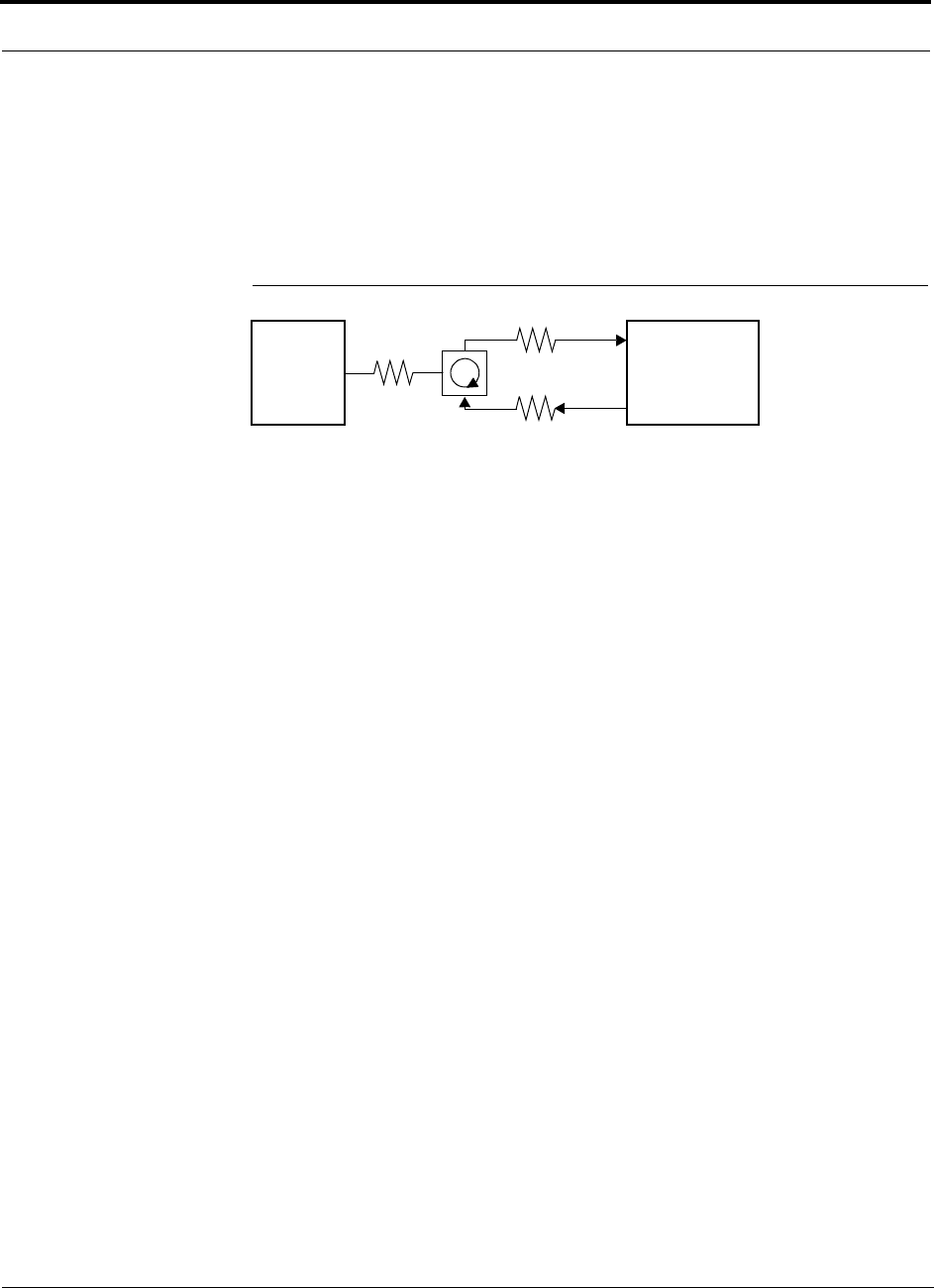
Figure 7-3 LGCell to Duplex Base Station or Repeater Connections
Duplex
Base Station LGCell
Main Hub
Forward
Reverse
A3
A1
A2
• A typical circulator has an IP3 of +70dBm. If you drive the circulator too hard it will produce
intermods that are bigger than the intermods produced by the LGCell. Depending on the
LGCell model, the IP3 at the Forward port input of the LGCell can be as high as +30 dBm.
The IP3 of the circulator at that same point (i.e., following attenuator A1) is +70dBm – A1.
Thus, to keep the system IP3 from being adversely affected by the circulator, attenuator A1
should be no more than 35 dB.
• A filter diplexer can be used in place of the circulator. The IP3 of the diplexer can be
assumed to be greater than +100 dBm. If a diplexer is used, A3 can be omitted.
• A1+A3 should be chosen so that the output power per carrier at the RAU’s output is correct
for the number of carriers being transmitted. Suppose the base station transmits 36 dBm
per carrier and it is desired that the RAU output be 6 dBm per carrier and the forward port
gain is 0 dB. Then A1+A3=30 dB.
• A2+A3 should, ideally, be at least 10 dB less than the noise figure plus the gain of the
LGCell. For example, if the reverse port has a 0 dB gain (it does for all current LGCell mod-
els) and if there are eight RAUs, the noise figure (depending on the LGCell model) is
approximately 25 dB. So A2+A3 should be about 10 to 15 dB. If A2+A3 is too large, the
uplink coverage distance can be severely reduced.
• Given these three equations:
A1 ≤ 35 dB
A1+A3 = 30 dB (in this example)
A2+A3 = 10 dB (in this example)
we could choose A1=20 dB, A2=0 dB, A3=10 dB for this example.
or
Repeater

PN 8100-40 Help Hot Line (U.S. only): 1-800-530-9960 7-43
620004-0 Rev. E
Connecting a Main Hub to a Base Station
7.5.2 Uplink Attenuation
The attenuation between the LGCell’s REVERSE port and the base station does two
things:
1. It attenuates the noise coming out of the LGCell.
2. It attenuates the desired signals coming out of the LGCell.
Setting the attenuation on the uplink is a trade-off between keeping the noise and
maximum signal levels transmitted from the LGCell to the base station receiver low
while not reducing the SNR (signal-to-noise ratio) of the path from the LGCell RAU
inputs to the base station inputs. This SNR can not be better than the SNR of the
LGCell by itself, although it can be significantly worse.
For example, suppose we have a GSM LGCell system consisting of one Main Hub,
four Expansion Hubs, and 16 RAUs (1-4-16) with uplink NF=28 dB. (See Table 7-27
on page 7-34.) If we use 30 dB of attenuation between the LGCell’s reverse port and
the base station (which has its own noise figure of about 4 dB), the overall noise fig-
ure will be 35 dB. (Refer to the formula on page 7-32.) Thus, by using this amount of
attenuation, the SNR is reduced by 7 dB. That causes a 7 dB reduction in the uplink
coverage distance. Now, if the attenuation instead is 0 dB, the cascaded noise figure is
NF=28.01 dB, which implies that the uplink sensitivity is limited by the LGCell, a
desirable condition. But now the maximum signal from the LGCell into the base sta-
tion is as high as –40 dBm. This can cause problems for some base stations. We can
reduce the maximum received signal levels by using some attenuation. For instance,
if the attenuation is 10 dB, the maximum received signal is –50 dBm and the noise
level is reduced by 10 dB but the cascaded noise figure is still only 28.16 dB (for a
SNR reduction of only 0.15 dB). Even with a 20 dB attenuator, the cascaded noise
figure is 29.45 dB. This is an SNR reduction of 1.44 dB. So, in this situation it would
be good to use at least 10 dB of uplink attenuation but not more than 20 dB.
Rule of Thumb
A good rule of thumb is to set the uplink attenuation, A2+A3 in Figure 7-3 on
page 7-42, as follows:
A2+A3 < LGCell uplink NF + uplink gain (0 dB for reverse port) – BTS NF – 10dB
and round A2 down to the nearest convenient attenuation value.

Designing an LGCell Solution
7-44 LGCell 4.0 Installation, Operation, and Reference Manual PN 8100-40
620004-0 Rev. E
7.5.2.1 Uplink Attenuation Exception: CDMA
In CDMA systems, the power transmitted by the mobile is determined by the charac-
teristics of both the uplink and downlink paths. The power transmitted by the mobile
should be similar in open-loop control (as determined by the downlink path) as dur-
ing closed-loop control (as determined by the uplink and downlink paths). In addi-
tion, the mobile’s transmit power when it communicates with a base station through
the LGCell should be similar to the power transmitted when it communicates with a
base station in the outdoor network (during soft hand-off). Because of these consider-
ations, you should not allow the downlink and uplink gains to vary widely.
Open-loop power control:
PTX = –76 dBm (for PCS) – PRX
where PTX is the power transmitted and PRX is the power received by the mobile. If
PL is the path loss (in dB) between the RAU and the mobile, and PDN is the downlink
power radiated by the RAU, then
PTX = –76 dBm (for PCS) – PDN + PL
Closed-loop power control:
PTX = noise floor + uplink NF – process gain + Eb/No + PL
= –113 dBm/1.25 Mhz + NF – 19 dB + 7 dB + PL
where Eb/No = 7 dB is a rough estimate, and NF is the cascaded noise figure of the
LGCell uplink, the uplink attenuation, and the base station noise figure. Equating PTX
for the open-loop and closed-loop we see that
NF = 49 – PDN
where PDN is determined by the downlink attenuation. Since PDN for the LGCell is
about 10 dBm, we see that the cascaded noise figure is about 39 dB, which is consid-
erably higher than that of the LGCell itself. This implies that we should use a fairly
large attenuation on the uplink. This case suggests using as much attenuation on the
downlink as on the uplink. The drawback of doing this is that the uplink coverage
sensitivity is reduced. A link budget analysis will clarify these issues. Typically, the
uplink attenuation between the LGCell and the base station will be the same as, or
maybe 10dB less than, the downlink attenuation.

PN 8100-40 Help Hot Line (U.S. only): 1-800-530-9960 7-45
620004-0 Rev. E
Designing for a Neutral Host System
7.6 Designing for a Neutral Host System
Designing the LGCell for a neutral host system uses the same design rules previously
discussed. Since a neutral host system typically uses multiple systems in parallel, we
find it best to design for the worst case system so that there will not be holes in the
covered area and the economies of a single installation can be achieved. For example,
as indicated Section 7.1, the 1900 MHz RF signals do not propagate throughout a
building as well as the 800 MHz systems, therefore, we design to the 1900 MHz path
loss formula.
7.6.1 Capacity of the LGCell Neutral Host System
As indicated in Section 2.3, “System Bandwidths,” on page 2-11, each Main Hub can
support more than one sub-band of the Cellular or PCS bands. The exception to this is
the iDEN Main Hub, because the SMR band is not split into sub-bands.
The 800 MHz Main Hub can support both the A band and the B band simultaneously.
Also, the 1800 MHz and 1900 MHz Main Hubs can support two bands each (as the
frequencies currently are allocated).
For example, a neutral host system that consists of one iDEN, one 800 MHz, and two
1900 MHz systems can support up to seven separate service providers:
• 1 on iDEN
• 2 on 800 MHz, A band and B band
• 2 in each 1900 MHz

Designing an LGCell Solution
7-46 LGCell 4.0 Installation, Operation, and Reference Manual PN 8100-40
620004-0 Rev. E
7.6.2 Example LGCell Neutral Host System
The following example configuration assumes:
• 0 dBm per carrier output
• Each System supports two bands, and therefore, two Operators
(Exception: iDEN supports one Operator)
Example Configuration:
• 800 MHz iDEN: System 1
l - iDEN system: 8 Channels, 23 voice calls
• 800 MHz Cellular: System 2
l - TDMA Band: 8 Channels, 23 voice calls
l - CDMA Band: 2 Channels, 30–40 voice calls
• 1900 MHz PCS: Systems 3 & 4 (2 band combinations/system)
l - TDMA Band: 8 Channels, 23 voice calls
l - CDMA Band: 2 Channels, 30–40 voice calls
l - GSM Band: 4 Channels, 31 voice calls
Number of subscribers* that could be served in this example:
• 800 MHz Cellular: System 1
l - iDEN Operator: 23 voice calls, 315 subscribers
• 800 MHz Cellular: System 2
l - TDMA Operator: 23 voice calls, 315 subscribers
l - CDMA Operator: 30–40 voice calls, 438–620 subscribers
• 1900 MHz PCS: Systems 3 & 4 (2 band combinations/system)
l - TDMA Operator: 23 voice calls, 315 subscribers
l - CDMA Operator: 30–40 voice calls, 438–620 subscribers
l - GSM Operator: 31 voice calls, 456 subscribers
This configuration supports growth for up to 7 Operators.
* Based on Standard Erlang B 2% GOS requirement. Each user has a 0.05 wireless Erlang which is higher than the standard 0.035
wireless Erlang.

PN 8100-40 LGCell 4.0 Installation, Operation, and Reference Manual 8-1
620004-0 Rev. E
SECTION 8 Installation Requirements and
Safety Precautions
This section contains the following subsections:
• Section 8.1 Installation Requirements . . . . . . . . . . . . . . . . . . . . . . . . . . . . . . . 8-2
• Section 8.1.1 Cable and Connector Requirements . . . . . . . . . . . . . . . . . . . 8-2
• Section 8.1.2 Neutral Host System Requirements . . . . . . . . . . . . . . . . . . . 8-2
• Section 8.1.3 Distance Requirements . . . . . . . . . . . . . . . . . . . . . . . . . . . . . 8-3
• Section 8.2 Safety Precautions . . . . . . . . . . . . . . . . . . . . . . . . . . . . . . . . . . . . 8-4
• Section 8.2.1 Underwriters Laboratory Installation Guidelines . . . . . . . . . 8-4
• Section 8.2.2 General Safety Precautions . . . . . . . . . . . . . . . . . . . . . . . . . . 8-5
• Section 8.2.3 Fiber Port Safety Precautions . . . . . . . . . . . . . . . . . . . . . . . . 8-6

Installation Requirements and Safety Precautions
8-2 LGCell 4.0 Installation, Operation, and Reference Manual PN 8100-40
620004-0 Rev. E
8.1 Installation Requirements
8.1.1 Cable and Connector Requirements
The LGCell equipment operates over standard TIA/EIA 568-A specification, Cate-
gory 5 (Cat-5) unshielded twisted pair (UTP) or shielded twisted pair (STP) and stan-
dard 62.5µm/125µm multimode fiber cable (MMF), at a wavelength of
1310 nanometers (nm).
These cables are widely used industry standards for Local Area Networks (LANs).
The regulations and guidelines for LGCell cable installation are identical to those
specified by the TIA/EIA 568-A standard for LANs.
European standards require that only STP cable be used. Also, to ensure specified
performance, STP cable is required in all multi-system installations that use parallel
Cat-5 cables in common ducting.
LGC Wireless recommends plenum-rated Cat-5 UTP/STP and MMF cable and con-
nectors for conformity to building codes and standards.
8.1.2 Neutral Host System Requirements
As in any LGCell system, a neutral host system requires one pair of MMF strands
between each Main Hub and each Expansion Hub, and one Cat-5 cable between each
Expansion Hub and each RAU. To help achieve the cost savings possible in a neutral
host system, it is advantageous to install additional cables for future growth.
To alleviate the possibility of interference between LGCell systems, STP cable is
required for neutral host systems.

PN 8100-40 Help Hot Line (U.S. only): 1-800-530-9960 8-3
620004-0 Rev. E
Installation Requirements
8.1.3 Distance Requirements
The following table shows the distances between LGCell components and related
equipment.
Table 8-1 LGCell Distance Requirements
Equipment Combination Cable Type Distance Additional Information
Repeater to Main Hub Coaxial; N male
connectors
3–6 m (10–20 ft) typical Limited by loss and noise.
Refer to your link budget
calculation.
Base Station to Main Hub Coaxial; N male
connectors
3–6 m (10–20 ft) typical Limited by loss and noise.
Refer to your link budget
calculation.
Main Hub to Expansion Hub 62.5µm/125µm
Multimode Fiber;
ST male optical con-
nectors
1 km (3300 ft) Up to 2 km (6600 ft) allowed.
(See “System Gain (Loss) Rel-
ative to MMF Cable Length”
on page 7-26.)
3 dB optical loss, port-to-port
Expansion Hub to RAU Cat-5 STP/UTP;
RJ-45 male connec-
tors
10 m (33 ft) absolute minimum
20 m (66 ft) recommended min.
50 m (165 ft) recommended max.
Up to 100 m (330 ft) allowed.
(See “System Gain (Loss) Rel-
ative to UTP/STP Cable
Length” on page 7-27.)
RAU to passive antenna Coaxial; SMA male
connectors
1–3.5 m (3–12 ft) typical Limited by loss and noise.
Refer to your link budget
calculation.

Installation Requirements and Safety Precautions
8-4 LGCell 4.0 Installation, Operation, and Reference Manual PN 8100-40
620004-0 Rev. E
8.2 Safety Precautions
8.2.1 Underwriters Laboratory Installation Guidelines
Use the following guidelines when installing the LGCell:
1. Do not exceed the maximum ambient air temperature of 45°C during operation.
Provide sufficient airflow and cooling within the rack to prevent heat build-up
from exceeding this limit.
2. Be careful when servicing these products. If you are removing the system from
the rack, turn it off and remove the power cord first. There are no user-serviceable
parts inside the hubs or RAUs.
3. Do not compromise the amount of airflow required for safe operation of the
equipment when installing it in a rack. Both the Main Hub and the Expansion Hub
draw in air on the left side and exhaust heated air at the rear. The hubs pass
approximately 6 cu. ft. of air per minute through themselves. The Main Hub dissi-
pates a maximum of 25 watts of heat from its internal circuitry and the Expansion
Hub dissipates a maximum of 55 watts (with 4 RAUs attached).
4. The AC input current consumption of the hubs is rated as follows:
•Main Hub
– Typical:
117V AC, 0.22 amp @ 60 Hz
230V AC, 0.11 amp @ 50 Hz
–Maximum:
117V AC, 0.30 amp @ 60 Hz
230V AC, 0.15 amp @ 50 Hz
• Expansion Hub
– Typical:
117V AC, 0.50 amp @ 60 Hz
230V AC, 0.25 amp @ 50 Hz
–Maximum:
117V AC, 0.70 amp @ 60 Hz
230V AC, 0.35 amp @ 50 Hz
The internal power supply has internal fuses that are not user replaceable. Con-
sider the worst-case power consumption shown on the product labels when provi-
sioning the rack’s AC power source and distribution.
PN 8100-40 Help Hot Line (U.S. only): 1-800-530-9960 8-5
620004-0 Rev. E
Safety Precautions
8.2.2 General Safety Precautions
The following precautions apply to LGCell products.
• LGCell has no user-serviceable parts. Faulty or failed units are fully replaceable
through LGC Wireless. Please contact us at:
1-800-530-9960 (U.S. only)
+1-408-952-2400 (International)
+44(0) 1223 597812 (Europe)
• Never input an RF signal to the Main Hub’s duplex or simplex ports that is higher
than those defined in Section 7.1 on page 7-3 because the Main Hub could be dam-
aged.
• Although modeled after an Ethernet/LAN architecture and connectivity, LGCell
units are not intended to connect to Ethernet data hubs, routers, cards, or other sim-
ilar data equipment.
• When you connect the multimode fiber (MMF) optical cable, take the same pre-
caution as if installing Ethernet network equipment. All optical fiber ST connec-
tors should be cleaned according to the connector manufacturer’s instructions.
• When you connect a radiating antenna to an RAU, DO NOT over-tighten the SMA
connector. Firmly hand-tightening the connector is adequate.
WARNING: To reduce the risk of fire or electric shock, do not expose
this equipment to rain or moisture.

Installation Requirements and Safety Precautions
8-6 LGCell 4.0 Installation, Operation, and Reference Manual PN 8100-40
620004-0 Rev. E
8.2.3 Fiber Port Safety Precautions
The following are suggested safety precautions for working with LGCell fiber ports.
For information about LGCell compliance with safety standards, see Appendix B.
WARNING: Observe the following warning about viewing fiber ends
in ports. Do not stare with unprotected eyes at the connector ends of
the fibers or the ports of the hubs. Invisible infrared radiation is
present at the front panel of the Main Hub and the Expansion Hub. Do not
remove the fiber port dust caps unless the port is going to be used. Do not stare
directly into a fiber port.
•Test fiber cables: When you test fiber optical cables, connect the optical power
source last and disconnect it first.
•Fiber ends: Cover any unconnected fiber ends with an approved cap. Do not use
tape.
•Broken fiber cables: Do not stare with unprotected eyes at any broken ends of the
fibers. Report any broken fiber cables and have them replaced.
•Cleaning: Use only approved methods for cleaning optical fiber connectors.
•Modifications: Do not make any unauthorized modifications to this fiber optical
system or associated equipment.
•Live work: Live work is permitted on the LGCell as it is a Class 1 hazard.
•Signs: No warning signs are required.
•Test equipment: Use Class 1 test equipment.
PN 8100-40 LGCell 4.0 Installation, Operation, and Reference Manual 9-1
620004-0 Rev. E
SECTION 9 Installing the LGCell
This section contains the following:
• Section 9.1 Inspecting Shipment . . . . . . . . . . . . . . . . . . . . . . . . . . . . . . . . . . . 9-2
• Section 9.2 Installing the Main Hub . . . . . . . . . . . . . . . . . . . . . . . . . . . . . . . . 9-3
• Section 9.3 Installing the Expansion Hub . . . . . . . . . . . . . . . . . . . . . . . . . . . 9-20
• Section 9.4 Installing the Remote Access Unit . . . . . . . . . . . . . . . . . . . . . . . 9-28
CAUTION:Although modeled after an Ethernet/LAN architecture,
LGCell units are not intended to be connected to Ethernet data hubs,
routers, or other similar data equipment.
NOTE: Only LGC Wireless personnel and approved Certified Installation Service
Provider (CISP) personnel are authorized to install LGCell systems. Frequency bands
are licensed for use by wireless operators.

Installing the LGCell
9-2 LGCell 4.0 Installation, Operation, and Reference Manual PN 8100-40
620004-0 Rev. E
9.1 Inspecting Shipment
Follow this procedure before installing LGCell equipment:
1. Verify the number of packages received against the packing list.
2. Check all packages for external damage; report any external damage to the ship-
ping carrier. If there is damage, a shipping carrier agent should be present before
unpacking and inspecting the contents because damage caused during transit is
the responsibility of the shipping agent.
3. Open and check each package against the packing slip. If any items are missing,
contact LGC Wireless customer service.
4. Do not remove items from antistatic packing until you are ready to install them. If
damage is discovered at the time of installation, contact the shipping agent.

PN 8100-40 Help Hot Line (U.S. only): 1-800-530-9960 9-3
620004-0 Rev. E
Installing the Main Hub
9.2 Installing the Main Hub
9.2.1 Main Hub Installation Checklist
Installation Requirement Consideration
Floor Plans Installation location of equipment clearly marked
Main Hub Same frequency and protocol as Expansion Hub(s)
AC power available Power cord is 2 m (6.5 ft) long
• 117V AC, 0.3 amp @ 60 Hz
• 230V AC, 0.15 amp @ 50 Hz
Rack space available 4.4 cm (1.75 in.) high
Clearance for air circulation 7.6 cm (3 in.) front and rear
Suitable operating environment 0° to 45°C (32° to 113°F)
5% to 95% non-condensing humidity
Donor Antenna-to-LGCell Configuration
Donor Antenna Installed, inspected; N-male to N-male coaxial cable to lightning arrestor/surge sup-
pressor
Lightning Arrestor or
Surge Suppressor
Installed between roof-top antenna and repeater; N-male to N-male coaxial cable
Repeater Installed between lightning arrestor/surge suppressor and Main Hub; N-male to
N-male coaxial cable
Base Station-to-LGCell Configuration
Microcellular Base Station Verify RF power (see tables in Section 7.1); N-male to N-male coaxial cable;
installed, inspected
Attenuation may be required to achieve the desired RF output per carrier at the RAU
LGCell Alarms to Base Station
Alarm cable If connecting one LGCell system to the base station, make custom cable on site.
If connecting multiple LGCell systems to the base station, use the 5-port
Daisy-Chain Alarm Cable (PN 4022-5). As necessary, make a custom cable to
mate the Daisy-Chain Alarm Cable to the base station’s input alarm connec-
tor port.
Cascading multiple Main Hubs
Power combiner/divider N-male to N-male coaxial cables; power combiner/divider to Main Hub and base
station or repeater
Cabling
Coax (Simplex) Coax approved; N-type male unidirectional connectors; repeater or base station to
Main Hub
Coax (Duplex) Coax approved; N-type male, bidirectional connectors; repeater or base station to
Main Hub
MMF 62.5µm/125µm; ST optical connectors, male; up to 1 km (3300 ft); Main Hub to
Expansion Hubs
Installing the LGCell
9-4 LGCell 4.0 Installation, Operation, and Reference Manual PN 8100-40
620004-0 Rev. E
9.2.2 Tools and Materials Required to Install Main Hub
The tools and materials required to install the Main Hub are listed in the following
table.
Distances
Main Hub is within 3–6m
(10–20 ft) of connecting
repeater
If longer distance, determine the loss of the cable used for this connection and adjust
the RF signal into the Main Hub accordingly. This can be done by readjusting the
power from the base station, or by changing the attenuation value between the base
station/repeater and the Main Hub.
Main Hub is within 3–6m
(10–20 ft) of connecting base
station
Main Hub is within 1 km (3300 ft) of Expansion Hub(s); 3 dB optical link budget
Miscellaneous
Cable manager Rack space immediately above or below the Main Hub; 8.9 cm (3.5 in.) high
Description
Philips screwdriver
Mounting screws and spring nuts
Fiber cleaning supplies (optical grade alcohol and lint-free wipes)
Compressed air (optical grade)
Installation Requirement Consideration

PN 8100-40 Help Hot Line (U.S. only): 1-800-530-9960 9-5
620004-0 Rev. E
Installing the Main Hub
9.2.3 Main Hub Installation Procedures
Procedures in this section:
• Installing the Main Hub in a Rack . . . . . . . . . . . . . . . . . . . . . . . . . . . . . . . . . . . 9-5
• Connecting Power and Powering Up . . . . . . . . . . . . . . . . . . . . . . . . . . . . . . . . . 9-6
• Installing an Optional Cable Manager in a Rack . . . . . . . . . . . . . . . . . . . . . . . . 9-6
• Connecting the MMF cables . . . . . . . . . . . . . . . . . . . . . . . . . . . . . . . . . . . . . . . 9-7
• Check the Main Hub Functionality LEDs . . . . . . . . . . . . . . . . . . . . . . . . . . . . . 9-8
• Check the Main Hub MMF Port LEDs . . . . . . . . . . . . . . . . . . . . . . . . . . . . . . . 9-8
• Connecting a Main Hub to a Roof-top Antenna . . . . . . . . . . . . . . . . . . . . . . . . 9-9
Installing the Main Hub in a Rack
The Main Hub (1U high) mounts in a standard 19 in. (48.3 cm) equipment rack.
Allow front and rear clearance of 7.6 cm (3 in.) for air circulation.
The Main Hub is shipped with #10-32 mounting screws. Another common rack
thread is #12-24. Confirm that the mounting screws match the racks threads.
1. Insert spring nuts into rack where needed or use existing threaded holes.
2. Place the Main Hub into the rack from the front.
3. Align the flange holes with the spring nuts installed in Step 1.
4. Insert the mounting screws in the appropriate positions in the rack.
5. Tighten the mounting screws.
Installing the LGCell
9-6 LGCell 4.0 Installation, Operation, and Reference Manual PN 8100-40
620004-0 Rev. E
Connecting Power and Powering Up
After mounting the Main Hub in the rack, connect AC power. You may use multiple
outlet surge protectors for multiple Main Hubs.
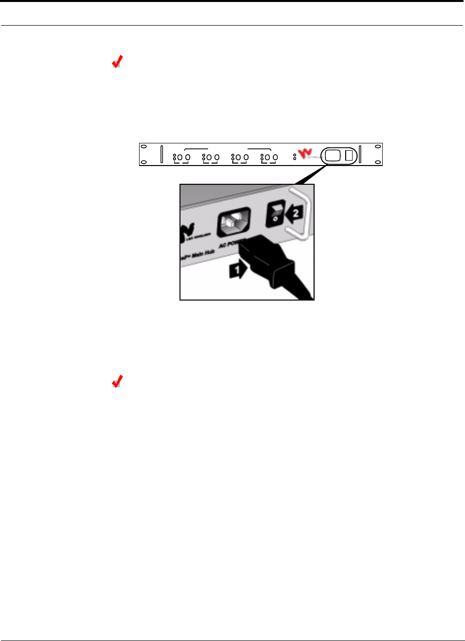
1. Connect the AC power cord to the Main Hub (labeled 1 on the following figure).
2. Plug the power cord into an outlet providing AC power.
3. Flip the Main Hub’s power switch from position 0 to position 1 (labeled 2 on the
figure above.)
The front panel unit functionality LEDs, POWER and SYNC, should be green (lit).
Installing an Optional Cable Manager in a Rack
• Fasten the cable manager to the rack, immediately above or below the Main Hub,
using screws.
AC P OWER
LGCell
TM
Main Hub
SYNC
POWER
LINK
SYNC
STATUS
DOWN UP
1
LINK
SYNC
STATUS
DOWN UP
2
LINK
SYNC
STATUS
DOWN UP
3
LINK
SYNC
STATUS
DOWN UP
4
TO EXPANSION HUB PORTS

PN 8100-40 Help Hot Line (U.S. only): 1-800-530-9960 9-7
620004-0 Rev. E
Installing the Main Hub
Connecting the MMF cables
Before connecting the MMF cables, confirm that the optical loss does not exceed
3 dB optical.
If fiber distribution panels are used, confirm that the total optical loss of fiber cable,
from the Main Hub through distribution panels and patch cords to the Expansion
Hub, does not exceed 3 dB optical.
Connect all MMF cables (two per port) to the MMF ST female optical connectors
(labeled DOWN and UP) on the Main Hub front panel. Use any available Main Hub
port.
To clean the fiber ports:
Use compressed air to blow dust out of each fiber port before you insert the ST opti-
cal connector. Note that compressed air should not leave any residue as this will con-
taminate the fiber port.
To clean the fiber connectors:
Be sure that the MMF cable ST optical connectors are clean and free of dust or oils. If
the fiber connector front face is not free of dust or oils, follow the manufacturer’s rec-
ommendations for cleaning it.
To connect the MMF cables:
The MMF cable is labeled with either 1 or 2, or is color-coded. This differentiates the
connectors for proper connection between the Main Hub and Expansion Hubs.
If the fiber jumper is labeled with 1 or 2:
1. Connect 1 to UP on Main Hub.
2. Connect 2 to DOWN on Main Hub.
3. Record which cable number you connected to UP and DOWN.
This information is needed when connecting the other end of the MMF cable to
the Expansion Hub ports.
If the fiber jumper is color-coded (for example, “blue” or “red”):
1. Connect “blue” to UP on Main Hub.
2. Connect “red” to DOWN on Main Hub.
3. Record which cable color you connected to UP and DOWN.
This information is needed when connecting the other end of the MMF cable to
the Expansion Hub ports.

Installing the LGCell
9-8 LGCell 4.0 Installation, Operation, and Reference Manual PN 8100-40
620004-0 Rev. E
Check the Main Hub Functionality LEDs
The unit functionality LEDs (POWER and SYNC) should be green. If not, cycle the
power to reset the Main Hub.
Check the Main Hub MMF Port LEDs
The MMF port LEDs (LINK STATUS and SYNC) should be red. This indicates that the
other end of the MMF cable is not yet connected to the Expansion Hub ports.
NOTE: Refer to Section 10 for troubleshooting LEDs.
NOTE: You do not have to use all of the MMF ports on the Main Hub. Unused ports
do not need to be terminated. Free ports can be used for future growth and to manage
changes in the in-building system.
PN 8100-40 Help Hot Line (U.S. only): 1-800-530-9960 9-9
620004-0 Rev. E
Installing the Main Hub
9.2.4 Interfacing LGCell to Base Stations
WARNING: Exceeding the maximum input power could cause fail-
ure of the Main Hub (refer to Section 7.1 on page 7-3 for maximum
power ratings). Attenuators may be required to limit the maximum
composite power into the Main Hub.
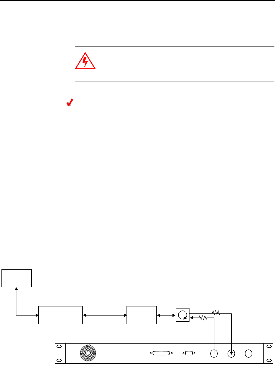
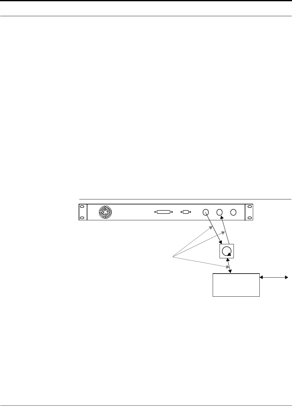
Connecting a Main Hub to a Roof-top Antenna
LGC Wireless recommends that you use a lightning arrestor or surge protector in a
roof-top antenna configuration. Insert the lightning arrestor or surge protector
between the roof-top antenna and the repeater that is connected to the Main Hub.
1. Connect an N-male to N-male coaxial cable to the roof-top antenna.
2. Connect the other end of the N-male to N-male coaxial cable to the grounded
surge suppressor.
3. Connect an N-male to N-male coaxial cable to the grounded surge suppressor.
4. Connect the other end of the N-male to N-male coaxial cable to the repeater.
5. Connect an N-male to N-male coaxial cable to the repeater.
6. Connect the other end of the N-male to N-male coaxial cable to the circulator
1connector.
7. Connect an N-male to N-male coaxial cable to the circulator 2connector.
8. Connect the other end of the N-male to N-male coaxial cable to the FORWARD
simplex connector on the Main Hub.
Attenuation may be required to achieve the desired RF output at the RAU.
9. Connect an N-male to N-male coaxial cable to the circulator 3connector.
10. Connect the other end of the N-male to N-male coaxial cable to the REVERSE sim-
plex connector on the Main Hub.
REVERSE FORWARD DUPLEX
DIAGNOSTIC 2 DIAGNOSTIC 1
Roof-top
Antenna
Grounded
Surge Suppressor Repeater
N-male to N-male
Coaxial Cables
N-male to N-male
Coaxial Cable
N-male to N-male
Coaxial Cable Circulator Attenuator
Installing the LGCell
9-10 LGCell 4.0 Installation, Operation, and Reference Manual PN 8100-40
620004-0 Rev. E
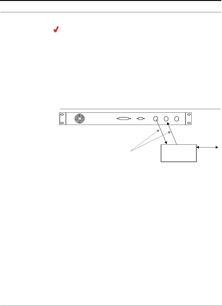
Connecting a Main Hub to an In-Building Base Station
Connecting a Simplex Base Station to a Main Hub:
1. Connect an N-male to N-male coaxial cable to the transmit simplex connector on
the base station.
2. Connect the other end of the N-male to N-male coaxial cable to the FORWARD
simplex connector on the Main Hub.
3. Connect an N-male to N-male coaxial cable to the receive simplex connector on
the base station.
4. Connect the other end of the N-male to N-male coaxial cable to the REVERSE sim-
plex connector on the Main Hub.
Figure 9-1 Simplex Base Station to LGCell Main Hub
REVERSE FORWARD DUPLEX
DIAGNOSTIC 2 DIAGNOSTIC 1
Microcellular
N-male to N-male
Coaxial Cable
Base Station
Simplex T1/E1 to
Mobile
Switching
Center
Insert attenuator, if needed
PN 8100-40 Help Hot Line (U.S. only): 1-800-530-9960 9-11
620004-0 Rev. E
Installing the Main Hub
Connecting a Duplex Base Station to a Main Hub:
When connecting to a duplex base station, it is recommended that you use a circulator
and connect to the simplex ports on the Main Hub.
You can insert attenuators between the base station and circulator, and between the
circulator and Main Hub as needed; refer to Section 7.5.1 on page 7-42 for more
information.
1. Connect an N-male to N-male coaxial cable to the duplex connector on the base
station.
2. Connect the other N-male connector to a circulator.
3. Connect an N-male to N-male coaxial cable to the FORWARD simplex connector
on the Main Hub.
4. Connect the other end of the N-male coaxial cable to the transmit connector on the
circulator.
5. Connect an N-male to N-male coaxial cable to the REVERSE simplex connector on
the Main Hub.
6. Connect the other end of the N-male coaxial cable to the receive connector on the
circulator.
Figure 9-2 Duplex Base Station to LGCell Main Hub
REVERSE FORWARD DUPLEX
DIAGNOSTIC 2 DIAGNOSTIC 1
Microcellular
N-male to N-male
Coaxial Cable
Base Station
Duplex T1/E1 to
Mobile
Switching
Center
Insert attenuator, if needed
N-male to N-male
Coaxial Cable
Circulator
Installing the LGCell
9-12 LGCell 4.0 Installation, Operation, and Reference Manual PN 8100-40
620004-0 Rev. E
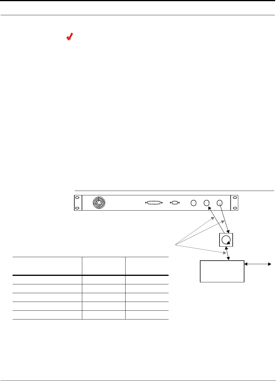
Using the Duplex Port to Increase Gain on the Uplink
Because some types of LGCells have duplex ports with gains of 0, 30, or 40 dB,
depending on the frequency and protocol, you can use the simplex forward port for
the downlink signals and the duplex port for the uplink signals when gain on the
uplink is desired. Duplex port gain is shown in the table in Figure 9-3.
Connecting a Duplex Base Station to the LGCell Duplex/Simplex Ports:
1. Connect an N-male to N-male coaxial cable to the duplex connector on the base
station.
2. Connect the other N-male connector to a circulator.
3. Connect an N-male to N-male coaxial cable to the FORWARD simplex connector
on the Main Hub.
4. Connect the other end of the N-male coaxial cable to the transmit connector on the
circulator.
5. Connect an N-male to N-male coaxial cable to the DUPLEX connector on the Main
Hub.
6. Connect the other end of the N-male coaxial cable to the receive connector on the
circulator.
Figure 9-3 Duplex Base Station to LGCell Main Hub
REVERSE FORWARD DUPLEX
DIAGNOSTIC 2 DIAGNOSTIC 1
Microcellular
N-male to N-male
Coaxial Cable
Base Station
Duplex T1/E1 to
Mobile
Switching
Center
Insert attenuator, if needed
N-male to N-male
Coaxial Cable
LGCell
Frequency/Format
Duplex Port
Gain (dB)
Simplex Port
Gain (dB)
800 MHz Cellular 30 0
800 MHz iDEN 0 0
900 MHz GSM / EGSM 0 0
1800 MHz DCS (GSM) 0 0
1900 MHz PCS 40 0
Circulator
PN 8100-40 Help Hot Line (U.S. only): 1-800-530-9960 9-13
620004-0 Rev. E
Installing the Main Hub
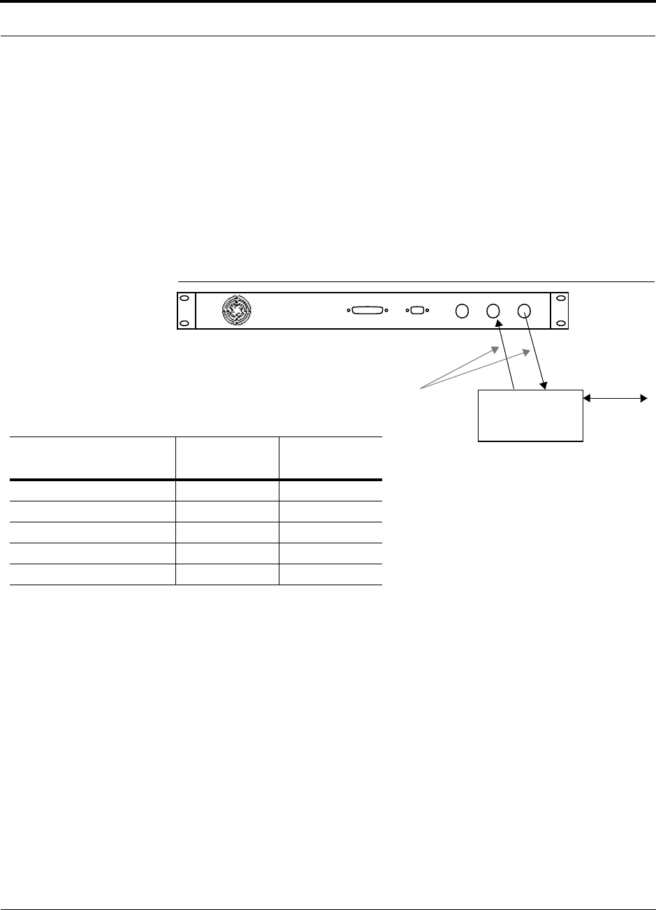
Connecting a Simplex Base Station to the LGCell Duplex/Simplex Ports:
1. Connect an N-male to N-male coaxial cable to the transmit connector on the base
station.
2. Connect the other end of the N-male coaxial cable to the FORWARD simplex con-
nector on the Main Hub.
3. Connect an N-male to N-male coaxial cable to the receive connector on the base
station.
4. Connect the other end of the N-male coaxial cable to the DUPLEX connector on the
Main Hub.
Figure 9-4 Duplex Base Station to LGCell Main Hub
REVERSE FORWARD DUPLEX
DIAGNOSTIC 2 DIAGNOSTIC 1
Microcellular
N-male to N-male
Coaxial Cable
Base Station
Simplex T1/E1 to
Mobile
Switching
Center
Insert attenuator, if needed
LGCell
Frequency/Format
Duplex Port
Gain (dB)
Simplex Port
Gain (dB)
800 MHz Cellular 30 0
800 MHz iDEN 0 0
900 MHz GSM / EGSM 0 0
1800 MHz DCS (GSM) 0 0
1900 MHz PCS 40 0
Installing the LGCell
9-14 LGCell 4.0 Installation, Operation, and Reference Manual PN 8100-40
620004-0 Rev. E
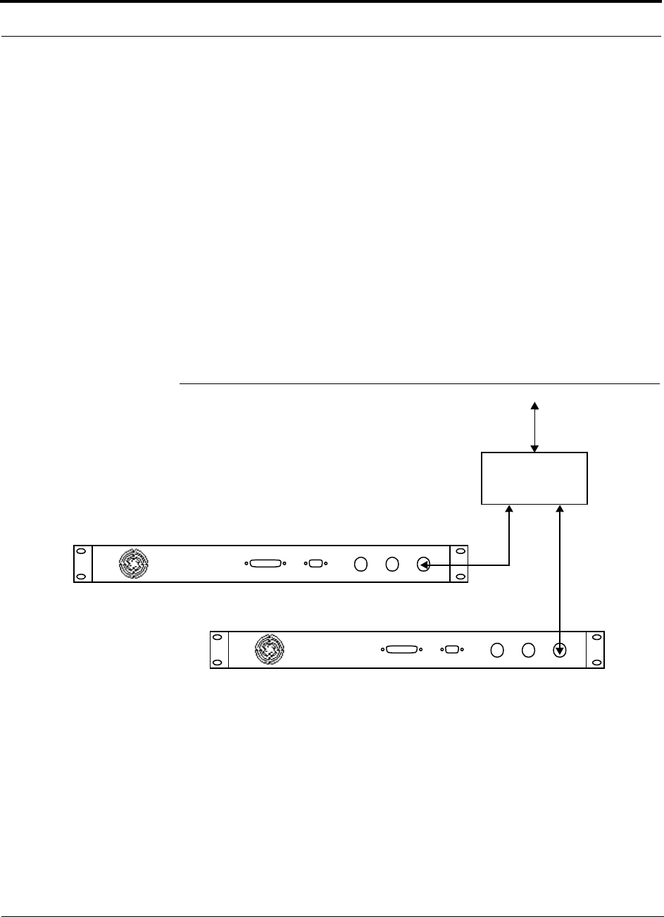
9.2.4.1 Connecting Multiple LGCell Systems to a Base Station
You can use power combiners/dividers as dividers to connect multiple LGCells in
order to increase the total number of RAUs in a system. You can use power combin-
ers/dividers to combine base station channels in order to increase the number of RF
carriers the system transports.
Connecting Two LGCells to a Base Station
Connecting two LGCells increases the total number of supportable RAUs from 16 to
32. Two Main Hubs support up to eight Expansion Hubs which in turn support up to
32 RAUs.
The following equipment is required:
• A 2x1 or 2x2 hybrid power combiner/divider
• 3 N-male to N-male coaxial jumper cables
Figure 9-5 Connecting Two LGCell Main Hubs using their Duplex Ports
REVERSE FORWARD DUPLEX
DIAGNOSTIC 2 DIAGNOSTIC 1
REVERSE FORWARD DUPLEX
DIAGNOSTIC 2 DIAGNOSTIC 1
2 x 1 Power
Combiner/Splitter
N-male to N-male
Coaxial Jumper Cable
N-male to N-male
Coaxial Jumper Cables
to Repeater or
Base Station

PN 8100-40 Help Hot Line (U.S. only): 1-800-530-9960 9-15
620004-0 Rev. E
Installing the Main Hub
Connecting Two LGCells to a Base Station
1. Connect the DUPLEX, FORWARD, or REVERSE connector of one of the Main Hubs
to an input/output port on the power combiner/divider using an N-male to N-male
coaxial cable jumper.
2. Connect the DUPLEX, FORWARD, or REVERSE connector of the second Main Hub
to the second input/output port on the power combiner/divider using an N-male to
N-male coaxial cable jumper.
3. Connect the combined port of the power combiner/divider to an base station or a
repeater using an N-male to N-male coaxial cable jumper.
4. Check the Main Hub LEDs.
After connecting the LGCells, check all Main Hub LEDs to ensure that the system
is operating properly.
Connecting More Than Two LGCells to a Base Station
Repeat this procedure to connect any number of LGCell systems. For three systems,
use a 3x1 power combiner/divider, and so on.
NOTE: When you are connecting multiple LGCells to the FORWARD and REVERSE
simplex ports, you will have to use a power combiner/divider for each direction. Ter-
minate each unused power combiner/divider port with a 50 ohm terminator.

Installing the LGCell
9-16 LGCell 4.0 Installation, Operation, and Reference Manual PN 8100-40
620004-0 Rev. E
9.2.5 Reporting LGCell Alarms to a Base Station
Report LGCell alarms to the base station by connecting the DIAGNOSTIC 1 port (see
“9-pin D-sub Connector” on page 3-7) on the Main Hub’s rear panel to the base sta-
tion’s alarm port.
Connecting a Single LGCell System’s Alarms to a Base Station
• Make a custom cable for this connection. See “9-pin D-sub Connector” on page
3-7 for the Main Hub’s alarm connector pin assignment.
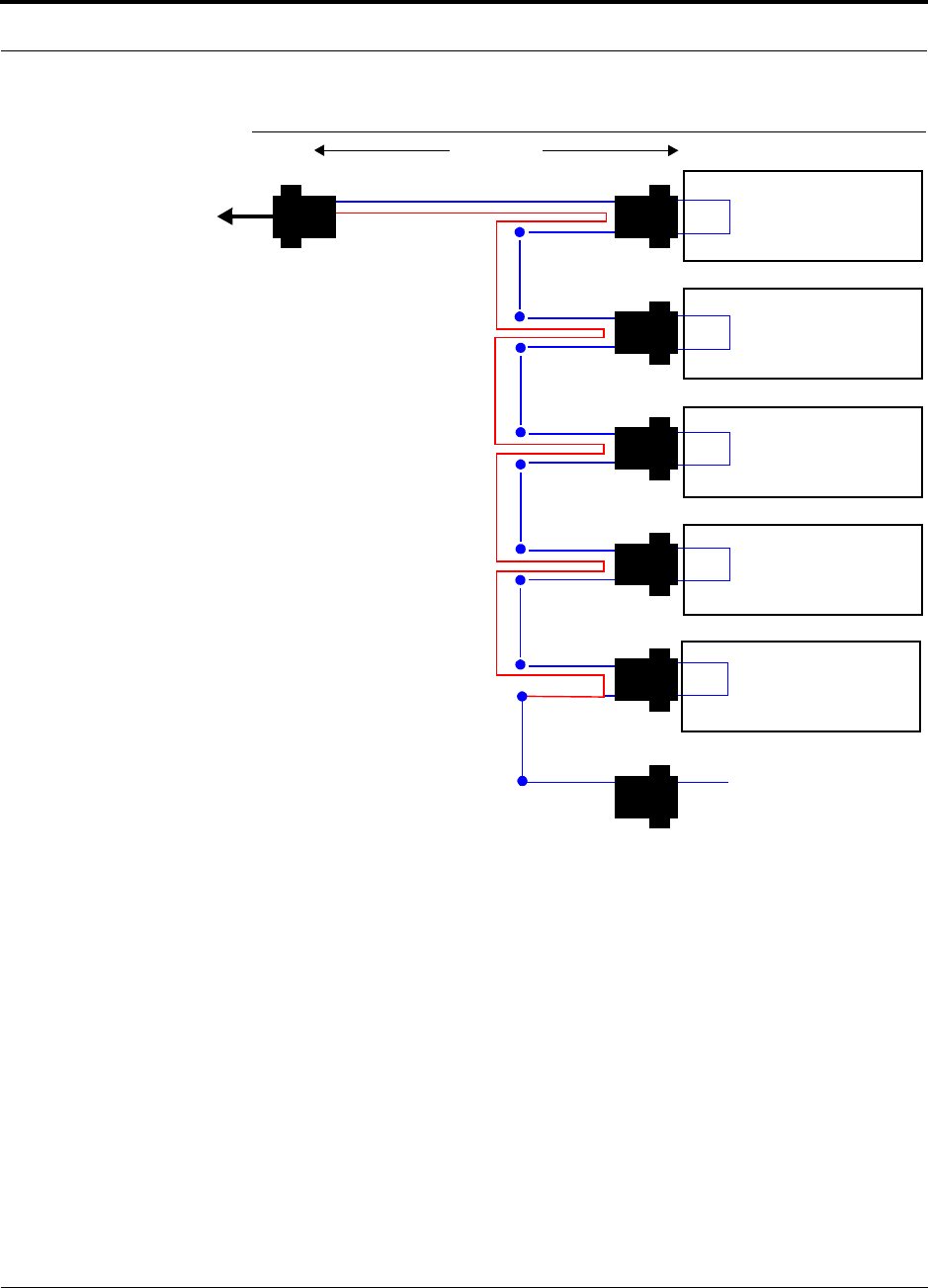
Connecting Multiple LGCell System’s Alarms to a Base Station
Use the 5-port Daisy-Chain Alarm Cable (PN 4022-5), shown in Figure 9-6, to route
alarms from multiple LGCells to the base station.
Depending on the base station’s alarm connector’s pin assignment, you may need to
make a custom adapter cable in order to connect the LGCell alarms to the base sta-
tion.
PN 8100-40 Help Hot Line (U.S. only): 1-800-530-9960 9-17
620004-0 Rev. E
Installing the Main Hub
Figure 9-6 5-port Daisy-Chain Alarm Cable
To connect 2 to 4 LGCell systems to a base station’s alarms:
1. Connect the alarm cable’s J2 connector to the DIAGNOSTIC 1 port on the first Main
Hub.
2. Connect the alarm cable’s J3 connector to the DIAGNOSTIC 1 port on the second
Main Hub, and so on.
3. Connect the J7 connector to the lowest numbered unused male connector (J2
through J6).
For example, when connecting 2 LGCell Main Hubs, connect J7 to J4 and leave
J5 and J6 unterminated.
Pin 7
Pin 9
X
1 meter (3 feet)
Pins 7 and 9
J2
Pin 7
Pin 9
X
J3
Pin 7
Pin 9
X
J4
Pin 7
Pin 9
X
J5
Pin 7
Pin 9
X
J6J7
DB-9 male
Pins 7 and 9
DB-9 male
Pins 7 and 9
DB-9 male
Pins 7 and 9
DB-9 male
Pins 7 and 9
DB-9 male
Pin 7
DB-9 female
J1
7
9
Pin 7
Option 1: Connect 5 units to cable using J2
through J6; J7 is unused.
OR
Option 2: Connect four units to first cable
using J2 through J5, connect J6 to an addi-
tional daisy-chain cable’s J1 connector; J7
is unused.
OR
Option 3: Connect fewer than four units to
cable and terminate the circuit by connect-
ing the J7 connector into the lowest num-
bered unused male connector.
LGCell Main Hub
Base Station
DIAGNOSTIC 1 Port
(an adapter
cable may be
required)
LGCell Main Hub
DIAGNOSTIC 1 Port
LGCell Main Hub
DIAGNOSTIC 1 Port
LGCell Main Hub
DIAGNOSTIC 1 Port
LGCell Main Hub
DIAGNOSTIC 1 Port

Installing the LGCell
9-18 LGCell 4.0 Installation, Operation, and Reference Manual PN 8100-40
620004-0 Rev. E
To connect 5 LGCell systems to a base station’s alarms:
• Connect the alarm cable’s J2 through J6 connectors to the DIAGNOSTIC 1 port on
five Main Hubs.
The J7 connector is unused and is left unterminated.
To connect more than 5 LGCell systems to a base station’s alarms:
1. Connect the first alarm cable’s J2 through J5 connectors to the DIAGNOSTIC 1 port
on four Main Hubs.
2. Connect the J1 connector of the second daisy-chain cable to the J6 connector on
the first cable; J7 is unused.
You can add daisy-chain cables to accommodate up to 21 Main Hubs in a single
chain.
3. Connect the J7 connector to the lowest numbered unused male connector (J2
through J6), if there is one.

PN 8100-40 Help Hot Line (U.S. only): 1-800-530-9960 9-19
620004-0 Rev. E
Installing the Main Hub
9.2.6 Installing Main Hubs in a Neutral Host System
Installing Main Hubs in a neutral host system is the same as described in
Section 9.2.3 on page 9-5.
We recommend mounting all neutral host system Main Hubs in the same rack(s),
grouped by frequency or carrier. For example, group the Main Hubs for the iDEN
carrier(s) together, then the 800 MHz Cellular carrier(s), and so on.
Connecting to base stations and repeaters is the same as described in Section 9.2.4 on
page 9-9 and Section 9.2.4.1 on page 9-14.

Installing the LGCell
9-20 LGCell 4.0 Installation, Operation, and Reference Manual PN 8100-40
620004-0 Rev. E
9.3 Installing the Expansion Hub
9.3.1 Expansion Hub Installation Checklist
9.3.2 Tools and Materials Required to Install Expansion Hub
The tools and materials required to install the Expansion Hub are listed in the follow-
ing table.
Installation Requirement Consideration
Floor Plans Installation location of equipment clearly marked
Expansion Hub Same frequency and protocol as Main Hub
AC power available Power cord is 2 m (6.5 ft) long
• 117V AC, 0.70 amp @ 60 Hz
• 230V AC, 0.35 amp @ 50 Hz
Rack space or wall mount location
available
4.4 cm (1.75 in.) high, 1U;
Clearance: 3 in. front and rear
Suitable operating environment 0° to 45°C (32° to 113°F)
5% to 95% non-condensing humidity
Cabling
Cat-5 UTP/STP TIA/EIA 568-A approved; RJ-45 male connectors; Expansion Hub to RAUs
• Absolute Minimum: 10 meters (33 ft)
• Recommended Minimum: 20 meters (66 ft)
• Maximum: 50 meters (165 ft)
MMF 62.5µm/125µm; ST optical connectors, male; up to 1 km (3300 ft); Expansion
Hub to Main Hub
Distances
Expansion Hub is within 1 km (3300 ft) of Main Hub (see Table 7-22 on page 7-26 if different MMF length)
Expansion Hub is within 10 m to 50 m (33 ft to 165 ft) of RAUs (see Table 7-22 on page 7-27 if different length)
Description
Philips screwdriver
Mounting screws and spring nuts
Power cord
Optional L brackets: Used to mount Expansion Hub to wall. (PN 4310 – single, PN 4311 – double)
6 anchors and 6 screws, or other suitable hardware (not provided): Used to attach L brackets to wall (3 for each bracket).
Fiber cleaning supplies (optical grade alcohol and lint-free wipes)
Compressed air (optical grade)
PN 8100-40 Help Hot Line (U.S. only): 1-800-530-9960 9-21
620004-0 Rev. E
Installing the Expansion Hub
9.3.3 Expansion Hub Installation Procedures
Procedures in this section:
• Installing the Expansion Hub . . . . . . . . . . . . . . . . . . . . . . . . . . . . . . . . . . . . . . 9-21
• Connecting Power and Powering Up . . . . . . . . . . . . . . . . . . . . . . . . . . . . . . . . 9-23
• Connect the MMF cables . . . . . . . . . . . . . . . . . . . . . . . . . . . . . . . . . . . . . . . . . 9-24
• Check the Expansion Hub Unit Functionality LEDs . . . . . . . . . . . . . . . . . . . . 9-25
• Check the Expansion Hub MMF Port LEDs . . . . . . . . . . . . . . . . . . . . . . . . . . 9-25
• Connect UTP/STP cables from the RAUs . . . . . . . . . . . . . . . . . . . . . . . . . . . . 9-26
Installing the Expansion Hub
The Expansion Hub (1U high) can mount in a standard 19 in. (48.3 cm) equipment
rack or attach to a wall.
The Expansion Hub is shipped with #10-32 mounting screws. Another common rack
thread is #12-24. Confirm that the mounting screws match the rack’s threads.
Installing the Expansion Hub in a rack:
1. Insert spring nuts into the rack where needed or use existing threaded holes.
2. Place the Expansion Hub into the rack from the front.
3. Align the flange holes with the spring nuts installed in Step 1.
4. Insert the mounting screws in the appropriate positions in the rack.
5. Tighten the mounting screws.
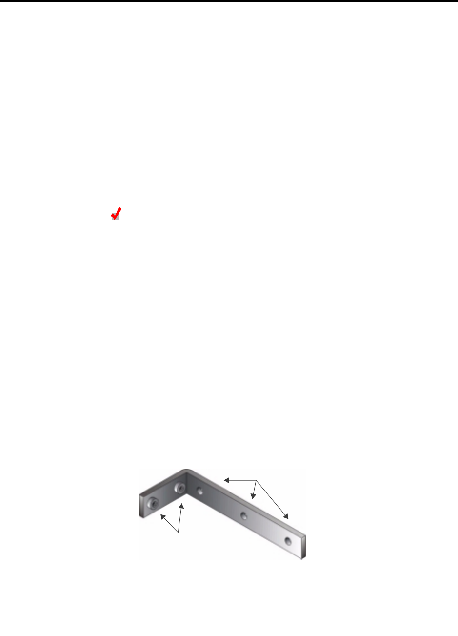
Mounting the Expansion Hub to a wall:
1. Attach the L brackets to the Expansion Hub.
Using the screws that came with the Expansion Hub, attach the L brackets to the
Expansion Hub’s rack-mounting holes.
2. Hold the Expansion Hub to the wall in the position where it will be mounted and
mark the pre-punched L bracket holes onto the wall for drilling.
Attach bracket
Attach bracket
to wall
to Expansion Hub
Installing the LGCell
9-22 LGCell 4.0 Installation, Operation, and Reference Manual PN 8100-40
620004-0 Rev. E
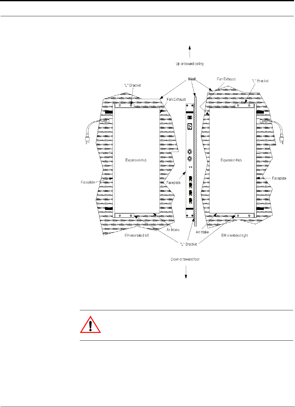
Refer to the following figure for wall mounting options.
3. Drill the screw holes in the wall and insert the anchors.
4. Attach the Expansion Hub to the wall with the screws.
CAUTION:Mounting the Expansion Hub facing up exposes the connec-
tors to falling dust and debris. Mounting it facing down exposes the fan to
falling dust and debris.
PN 8100-40 Help Hot Line (U.S. only): 1-800-530-9960 9-23
620004-0 Rev. E
Installing the Expansion Hub
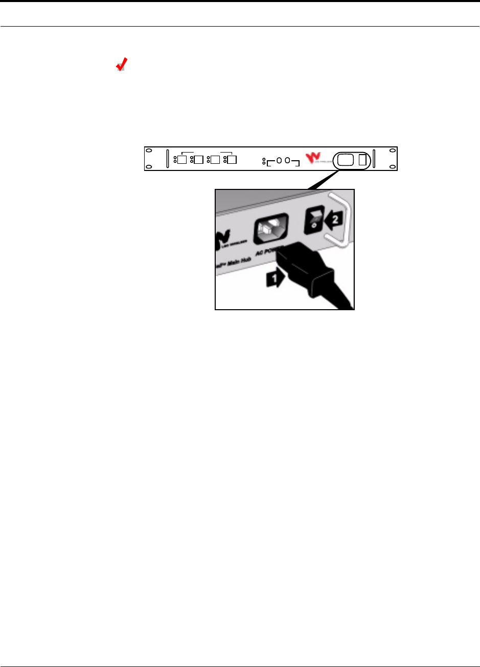
Connecting Power and Powering Up
After mounting the Expansion Hub, connect the AC power.
1. Connect the AC power cord to the Expansion Hub (labeled 1 on the following fig-
ure).
2. Plug the power cord into an outlet providing AC power.
3. Flip the Expansion Hub’s power switch from position 0 to position 1 (labeled 2 on
the figure.)
The front panel POWER LED should be green (lit) and the unit SYNC LED should
be off.
AC POWER
LGCell
TM
Expansion Hub
SYNC
POWER
SYNC
LINK
STATUS
ANTENNA PORTS
DOWN UP
MAIN HUB PORT

Installing the LGCell
9-24 LGCell 4.0 Installation, Operation, and Reference Manual PN 8100-40
620004-0 Rev. E
Connect the MMF cables
Before connecting the MMF cables, confirm that the optical loss does not exceed
3dB optical.
If fiber distribution panels are used, confirm that the total optical loss of fiber cable,
from the Main Hub through distribution panels and patch cords to the Expansion
Hub, does not exceed 3 dB optical.
Connect all MMF cables from the Main Hub to the Expansion Hub(s).
To clean the fiber ports:
Use compressed air to blow dust out of each fiber port before you insert the ST opti-
cal connector. Note that compressed air should not leave any residue as this will con-
taminate the fiber port.
To clean the fiber connectors:
Be sure that the MMF cable ST optical connectors are clean and free of dust or oils. If
the fiber connector front face is not free of dust or oils, follow the manufacturer’s rec-
ommendations for cleaning it.
To connect the MMF cables:
The MMF cable is labeled with either 1 or 2, or is color-coded. This differentiates the
connectors for proper connection between the Main Hub and Expansion Hubs. For
proper connection between the Main Hub ports and the Expansion Hub ports, refer to
the numbered or color-coded connections that were recorded when the Main Hub ws
installed.
If the fiber jumper is labeled with 1 or 2:
1. Connect 1 to UP on Expansion Hub.
2. Connect 2 to DOWN on Expansion Hub.
If the fiber jumper is color-coded (for example, “blue” or “red”):
1. Connect “blue” to UP on Expansion Hub.
2. Connect “red” to DOWN on Expansion Hub.
PN 8100-40 Help Hot Line (U.S. only): 1-800-530-9960 9-25
620004-0 Rev. E
Installing the Expansion Hub
Check the Expansion Hub Unit Functionality LEDs
The unit functionality LEDs (POWER and SYNC) should be green if the Main Hub is on.
Check the Expansion Hub MMF Port LEDs
The MMF port LEDs (LINK STATUS and SYNC) should be red. This indicates that the
UTP/STP cable is not yet connected to the Remote Access Unit(s).
Check the Main Hub MMF Port LEDs
The MMF port LEDs (LINK STATUS and SYNC) should be green.
NOTE: Refer to Section 10 for troubleshooting LEDs.
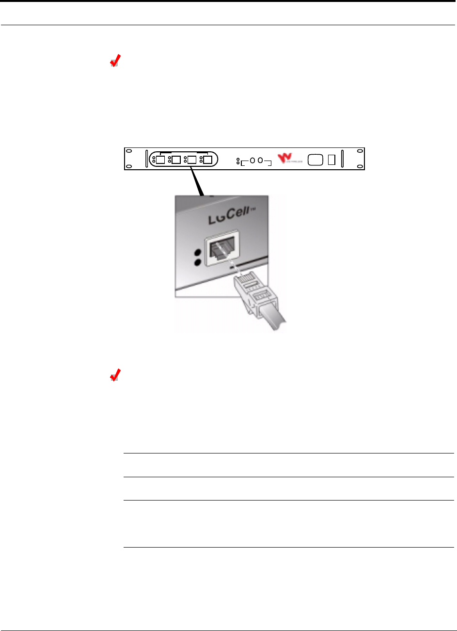
Installing the LGCell
9-26 LGCell 4.0 Installation, Operation, and Reference Manual PN 8100-40
620004-0 Rev. E
Connect UTP/STP cables from the RAUs
Before connecting the UTP/STP cables, confirm that they meet TIA/EIA 568-A spec-
ifications.
Connect all UTP/STP cables coming from the RAUs to any available RJ-45 connec-
tor on the Expansion Hub, as shown in the following figure. Make sure you connect
RAUs that are of the correct frequency and protocol.
Check the Expansion Hub Cat-5 Port LEDs
The Expansion Hub Cat-5 port LINK STATUS and SYNC LEDs should be green if the
RAUs are connected on the other end of the UTP/STP cable.
The Cat-5 port LEDs should be red if the RAUs are not yet connected.
NOTE: Refer to Section 10 for troubleshooting LEDs.
NOTE: You do not have to use all of the Cat-5 ports on the Expansion Hub. Unused
ports do not need to be terminated. Free ports can be used for future growth and to
manage changes in the in-building system.
AC PO WER
LGCell
TM
Expansion Hub
SYNC
POWER
SYNC
LINK
STATUS
ANTENNA PORTS
DOWN UP
MAIN HUB PORT

PN 8100-40 Help Hot Line (U.S. only): 1-800-530-9960 9-27
620004-0 Rev. E
Installing the Expansion Hub
9.3.4 Installing Expansion Hubs in a Neutral Host System
Installing neutral host system Expansion Hubs is the same as described in
Section 9.3.3 on page 9-21.
If rack-mounting the Expansion Hubs, we recommend mounting all neutral host sys-
tem hubs in the same rack(s) or location, grouped by frequency or carrier. For exam-
ple, group the Expansion Hubs for the iDEN carrier(s) together, then the 800 MHz
Cellular carrier(s), and so on.
Installing the LGCell
9-28 LGCell 4.0 Installation, Operation, and Reference Manual PN 8100-40
620004-0 Rev. E
9.4 Installing the Remote Access Unit
9.4.1 Remote Access Unit Installation Checklist
9.4.2 Tools and Materials Required to Install Remote Access Unit
The tools and supplies required to install the RAU depends on the installation method
selected; the following table lists suggestions.
Installation Requirement Consideration
Floor Plans Installation location of equipment clearly marked
Remote Access Unit(s) 4 per Expansion Hub
Passive antennas Coaxial cable terminated correctly
Suitable operating environment
Cabling
Cat-5 UTP/STP TIA/EIA 568-A approved; RJ-45 male connectors; RAU to Expansion Hub
• Absolute Minimum: 10 meters (33 ft)
• Recommended Minimum: 20 meters (66 ft)
• Maximum: 50 meters (165 ft)
Coaxial Use low-loss cable; RAU (SMA male connector) to passive antennas; typical 1 m
(3.3 ft) using RG142 coaxial cable
Distance
RAU is within 10 m to 50 m (33 ft to 165 ft) of Expansion Hub (see Table 7-22 on page 7-27 if different UTP/STP
length)
RAU is within RF-design distance of passive antenna, typically 1 m (3.3 ft); coverage will be affected if coaxial cable
length differs from what was used to calculate the design plan
Description
Philips screwdriver
Tie Wraps
Screws
Drywall Anchors
Pipe Clamp
RAU Mounting Plate
Drill
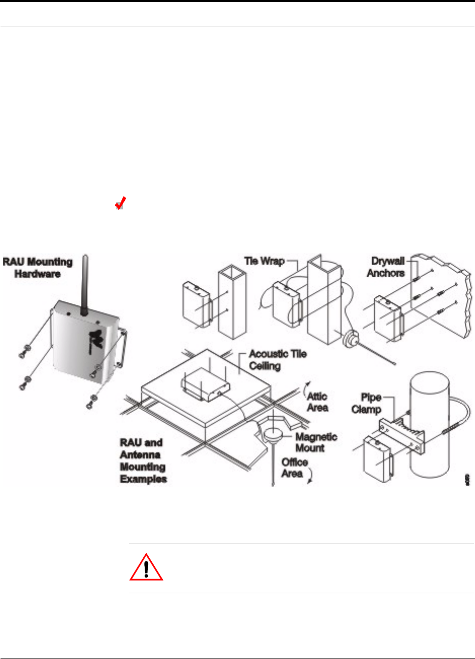
PN 8100-40 Help Hot Line (U.S. only): 1-800-530-9960 9-29
620004-0 Rev. E
Installing the Remote Access Unit
9.4.3 RAU Installation Procedures
Procedures in this section:
• Mounting RAUs . . . . . . . . . . . . . . . . . . . . . . . . . . . . . . . . . . . . . . . . . . . . . . . . 9-29
• Connecting the Antenna . . . . . . . . . . . . . . . . . . . . . . . . . . . . . . . . . . . . . . . . . . 9-30
• Installing Passive Antennas . . . . . . . . . . . . . . . . . . . . . . . . . . . . . . . . . . . . . . . 9-30
• Connecting the UTP/STP Cable . . . . . . . . . . . . . . . . . . . . . . . . . . . . . . . . . . . . 9-31
• Check the RAU LEDs . . . . . . . . . . . . . . . . . . . . . . . . . . . . . . . . . . . . . . . . . . . 9-32
Mounting RAUs
Mount all RAUs in their assigned locations. Refer to the following figure for mount-
ing options.
CAUTION:Install iDEN and 800 MHz Cellular RAUs so that their anten-
nas will be 6 to 8 meters (20 to 26 feet) apart. See Section 9.4.4 on page
9-33 for more information.
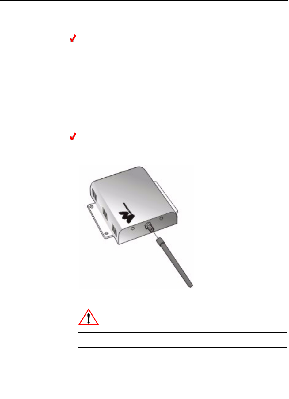
Installing the LGCell
9-30 LGCell 4.0 Installation, Operation, and Reference Manual PN 8100-40
620004-0 Rev. E
Installing Passive Antennas
Refer to the manufacturer’s installation instructions to install passive antennas.
Passive antennas are usually installed below the ceiling. If they are installed above
the ceiling, the additional loss due to the ceiling material must be considered when
estimating the antenna coverage area.
Considerations:
• Use coaxial cable with the least amount of loss possible.
• Keep iDEN and 800 MHz cellular antennas 6 to 8 meters (20 to 26 ft) apart.
Connecting the Antenna
Connect a passive antenna to the SMA female connector on the RAU. The following
figure shows connecting an optional antenna to a single band RAU.
CAUTION:When connecting to the SMA female connector on the RAU
and passive antenna, DO NOT over-tighten the connector. Firmly
hand-tightening the connector is adequate.
NOTE: If an RAU is installed but an antenna is not connected, the SMA port must
be terminated with a 50 ohm terminator (LGC part number 4100).
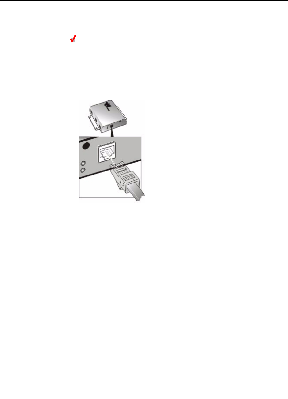
PN 8100-40 Help Hot Line (U.S. only): 1-800-530-9960 9-31
620004-0 Rev. E
Installing the Remote Access Unit
Connecting the UTP/STP Cable
Connecting UTP/STP to single band RAU:
Before connecting the UTP/STP cables, confirm that they meet TIA/EIA 568-A spec-
ifications.
Connect the UTP/STP cable coming from the Expansion Hub to the RJ-45 female
jack on the RAU, as shown in the following figure.
Connecting UTP/STP cable to dual band RAU:
• For the 900/1800 dual band RAU:
Connect the 900 MHz Expansion Hub cable to the top RJ-45 jack and the
1800 MHz cable to the bottom RJ-45 jack.
• For the 800/900 or 800/1900 dual band RAU:
Connect the 800 MHz Expansion Hub cable to the left RJ-45 jack and the
900 MHz or 1900 MHz cable to the right RJ-45 jack.
• For the 1800/1800 dual band RAU:
Connect the top (upper) 1800 MHz Expansion Hub cable to the RAU’s top RJ-45
jack, and connect the bottom (lower) 1800 MHz Expansion Hub cable to the
RAU’s bottom RJ-45 jack.
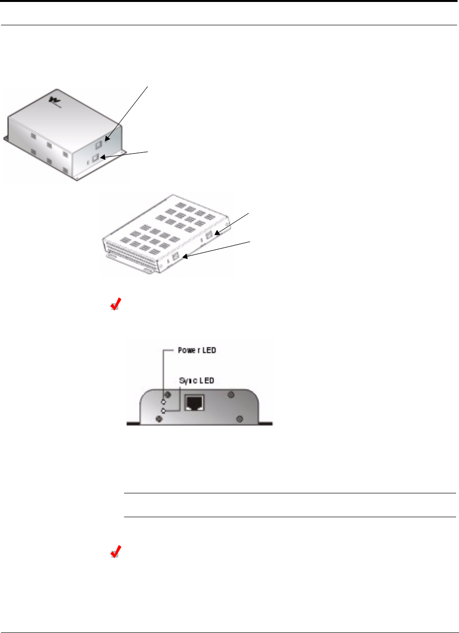
Installing the LGCell
9-32 LGCell 4.0 Installation, Operation, and Reference Manual PN 8100-40
620004-0 Rev. E
The RJ-45 jacks on both the vertical and horizontal style dual band RAUs are shown
in the following figure.
Check the RAU LEDs
The green POWER LED should be on and the red SYNC LED should be off.
The green POWER LED should be lit to indicate that the RAU is receiving power
from the Expansion Hub.
The green POWER LED should be off if the Expansion Hub is not yet connected.
NOTE: Refer to Section 10 for troubleshooting LEDs.
Check the Expansion Hub MMF Port LEDs
Re-check the Expansion Hub LEDs to verify that the RAUs are operating properly.
The Expansion Hub fiber port LINK STATUS and SYNC LEDs should be green if the
RAUs are connected on the other end of the UTP/STP cable.
Top RJ-45 female connector:
900/1800 dual band system: 900 MHz Expansion Hub cable
1800/1800 dual band system: top (upper) Expansion Hub cable
Bottom RJ-45 female connector:
900/1800 dual band system: 1800 MHz Expansion Hub cable
1800/1800 dual band system: bottom (lower) Expansion Hub cable
800/1900 dual band system: 1900 MHz Expansion Hub cable
800/1900 dual band system: 800 MHz Expansion Hub cable
800/900 dual band system: 900 MHz Expansion Hub cable
800/900 dual band system: 800 MHz Expansion Hub cable
Right RJ-45 female connector:
Left RJ-45 female connector:

PN 8100-40 Help Hot Line (U.S. only): 1-800-530-9960 9-33
620004-0 Rev. E
Installing the Remote Access Unit
9.4.4 Installing Remote Access Units in a Neutral Host System
When installing both iDEN and Cellular systems in parallel, either as dual-band or
neutral host systems, special provision must be taken to assure that the individual
RAUs do not interfere with each other.
It is recommended that the 800 MHz Cellular and the 800 MHz iDEN RAU’s
antennas be separated by 6 to 8 meters (20 to 26 feet), to assure that the iDEN
downlink signals do not interfere with the Cellular uplink signals.

Installing the LGCell
9-34 LGCell 4.0 Installation, Operation, and Reference Manual PN 8100-40
620004-0 Rev. E

PN 8100-40 LGCell 4.0 Installation, Operation, and Reference Manual 10-1
620004-0 Rev. E
SECTION 10 Maintenance, Troubleshooting,
and Technical Assistance
There are no user-serviceable parts in any of the LGCell components. Faulty or failed
components are fullly replaceable through LGC Wireless.
Address 2540 Junction Avenue
San Jose, California
95134-1902 USA
Phone 1-408-952-2400
Fax 1-408-952-2410
Help Hot Line 1-800-530-9960 (U.S. only)
+1-408-952-2400 (International)
+44(0) 1223 597812 (Europe)
Web Address http://www.lgcwireless.com
e-mail service@lgcwireless.com
10.1 Maintenance
No periodic maintenance of the LGCell equipment is required.

Maintenance, Troubleshooting, and Technical Assistance
10-2 LGCell 4.0 Installation, Operation, and Reference Manual PN 8100-40
620004-0 Rev. E
10.2 Troubleshooting
NOTE: LGCell has no user-serviceable parts. Faulty or failed units are
fully replaceable through LGC Wireless.
Sources of potential problems include:
• Malfunction of one or more LGCell components
• Faulty cabling/connector
• Antenna, base station, or repeater problem
• External RF interface
NOTE: Faulty cabling is the cause of a vast majority of problems. All Cat-5
cable should be tested to TIA/EIA 568-A specifications.
The diagnostic procedures are based on diagnostic information in Table 10-2 on
page 10-5. The table lists all LEDs and indicates what to do under certain circum-
stances. There is a blank table at the end of this section that you can copy and use to
record the LEDs while you troubleshoot an LGCell system.
If you cannot determine the cause of a problem after following the recommended pro-
cedures, call LGC Wireless customer help hot line:
1-800-530-9960 (U.S. only)
+1-408-952-2400 (International)
+44(0) 1223 597812 (Europe)

PN 8100-40 Help Hot Line (U.S. only): 1-800-530-9960 10-3
620004-0 Rev. E
Troubleshooting
10.2.1 Troubleshooting Guidelines
The following table contains troubleshooting information that the diagnostic LEDs do
not cover. Please check the table for a possible cause of a problem. Simple checks or
minor adjustments might eliminate the problem and restore proper operation.
Problem/Symptom Check
No downlink signal
output when all diag-
nostic LEDs are green
Make sure that there is a reasonable amount of power at the input of the Main Hub. Use a power
meter to measure the output power from the coaxial cable that feeds the Main Hub.
The LGCell is intended for a different frequency band. Verify that your system corresponds to the
desired frequency (for example, 800 MHz, 1800 MHz, or 1900 MHz).
Check the part number of each unit to be sure you have the proper band (e.g., DAS19M-4A-AD is
the part number for a Main Hub set up for 1900 MHz A and D bands).
The system gain is
lower than specifica-
tion
The optical fiber connector may be dirty. Clean the ST optical connector, using the manufacturer’s
recommended cleaning procedure.
There are two types of multimode fiber (MMF), 62.5µm/125µm and 50µm/125µm. Make sure the
vertical run of MMF is the 62.5µm/125µm type of fiber.
Check the length of MMF and UTP/STP cabling.
Remote Access Unit
(RAU) power LED
(green LED) stays off
after you plug in the
twisted pair cable
The Expansion Hub provides power to the RAU. Make sure the Expansion Hub is on.
Make sure that the twisted-pair (TP) cable wiring conforms to the TIA/EIA 568-A standard. Use a
standard local area network (LAN) cable tester to perform this test. Make sure the Cat-5 is not
plugged into the Expansion Hub when doing this test. Possible errors are incorrect wiring and/or
cable length.
The LGCell perfor-
mance is intermittent
when you use it for the
CDMA application
The uplink and downlink gains are not balanced. A CDMA system performs active power control
between the base station and the mobile unit. It is important to maintain a balanced link from the
base station ports to the RAU ports (equal uplink and downlink gain) to optimize the performance of
the LGCell.
Possible MMF port
problem on a Main
Hub
To isolate possible port problems on a Main Hub try moving the faulty fiber pair to another port on
the hub or to another Main Hub.
When you move an active fiber pair, the Main Hub remembers that there was fiber on that port and
issues an alarm. You must clear the latched alarm (port disconnect memory feature) by cycling Main
Hub power.
Possible RJ-45 port
problem on an Expan-
sion Hub
Move the Cat-5 to a spare port or swap the Cat-5 to try and isolate the problem.
The Expansion Hub also has port disconnect memory to track which ports have been connected. So
when a Cat-5 is disconnected and moved to a new port, an alarm will be issued. You must cycle
power to the Expansion Hub to clear the memory and the latched alarm.
If the Expansion Hub is suspect, try and remove all RAUs to eliminate any possible RAU failure and
then begin to put RAUs back in. Remember to cycle power whenever a RAU is removed.
Possible RAU prob-
lem
When working RAU problems, an RAU whose functionality has been confirmed can be used with
about 15 m (50 ft) of Cat-5 to quickly verify ports on an Expansion Hub. Simply connect the RAU to
one end of the cable and plug the other end into the Expansion Hub ports to verify proper operation.
Troubleshoot down-
link problem on an
active system
Downlink problems can be troubleshot on an active system by injecting a low-level signal at the
Main Hub using the unused port (either the duplex bidirectional port or the simplex downlink port).
Then you can go out to the RAU and perform some measurements without disrupting normal ser-
vice.
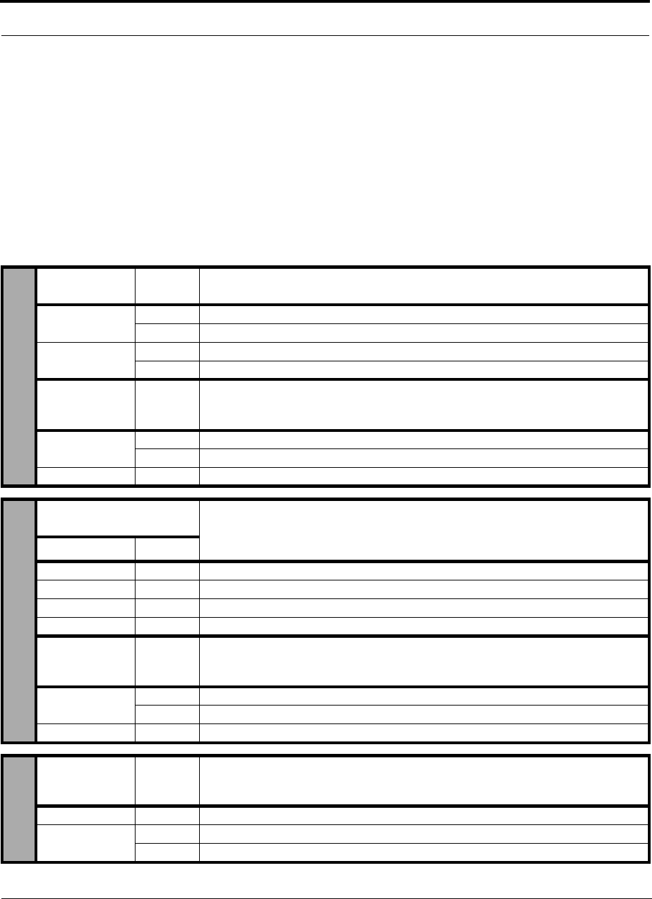
Maintenance, Troubleshooting, and Technical Assistance
10-4 LGCell 4.0 Installation, Operation, and Reference Manual PN 8100-40
620004-0 Rev. E
10.2.2 Troubleshooting Using the LED Indicators
10.2.2.1 LED Indicator Description
The LGCell Main Hub, Expansion Hubs, and RAUs have front panel LEDs which
provide diagnostic information and operational status of each unit. Together they pro-
vide an efficient diagnostic display system, which help technicians find the fault if
there is a malfunction. The LED indicators for each unit are described in the follow-
ing table.
Table 10-1 LGCell Equipment LED Indicators
MMF Port
Indicators Color Indicates
LINK STATUS Green Good connection to the Expansion Hub that is connected to the port.
Red Connection problem with the Expansion Hub that is connected to the port.
SYNC Green Expansion Hub connected to the port is operating properly.
Red An alarm with the Expansion Hub that is connected to the port.
Unit
Functionality
Indicators Color Indicates
SYNC Green Main Hub is correctly producing the synchronization signal.
Off Main Hub is not correctly producing the synchronization signal.
POWER Green Main Hub has power.
UTP/STP Port
Indicators/Color
Indicates
LINK STATUS SYNC
Green Green RAU is connected and functioning properly.
Green Red RAU is connected but malfunctioning.
Red Green RAU has been disconnected or the cable is cut.
Red Red No RAU is connected.
Unit
Functionality
Indicators Color Indicates
SYNC Green Expansion Hub is receiving the synchronization signal from the Main Hub.
Off A fault with the MMF downlink or the unit is faulty.
POWER Green Expansion Hub has power.
Unit
Functionality
Indicators Color Indicates
POWER Green RAU is receiving power from the Expansion Hub.
SYNC Red RAU lost sync and has shut down RF power.
Off No fault.
MAIN HUBEXPANSION HUBRAU
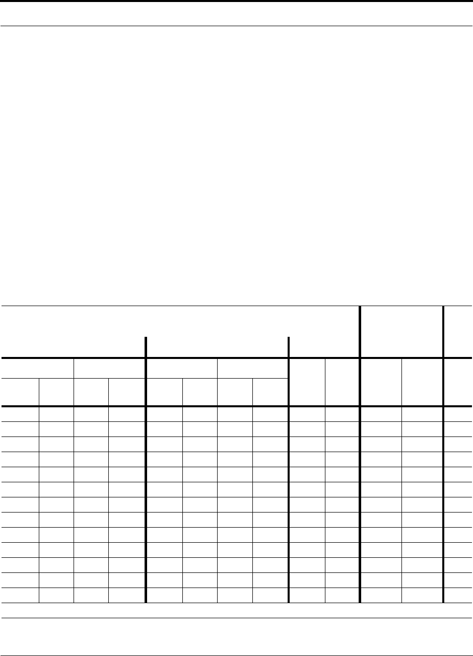
PN 8100-40 Help Hot Line (U.S. only): 1-800-530-9960 10-5
620004-0 Rev. E
Troubleshooting
10.2.2.2 Diagnostic Procedures
Use the following table when diagnosing system problems. For troubleshooting, you
can copy the blank table on page 10-8 and use it to record the LED colors on the Main
Hub, the particular Expansion Hub indicating a fault, and the RAUs connected to it.
This is necessary because the Main Hub, Expansion Hubs, and RAUs typically are
geographically distributed.
To determine where the fault might be:
1. Go to the Main Hub and record the LEDs. The Main Hub indicates which Expan-
sion Hub may be faulty by lighting one of its port LEDs red.
2. Go to the Expansion Hub attached to the port that has a red LED.
3. Record that Expansion Hub’s LEDs. The Expansion Hub indicates which RAU(s)
may be faulty by lighting its antenna LED red.
4. Go to the RAU(s) connected to the Expansion Hub port that is indicating a fault.
Record the error.
5. Compare your filled in table to the Diagnostic Table below and begin trouble-
shooting according to the notes indicated for your situation.
Table 10-2 LED Diagnostics
Visual Alarm LEDs Remote Alarm
Contacts
Main Hub Expansion Hub RAU DB-9 Connector
Port Functionality Port Functionality
Power Sync
Major
Alarm
Contact
Error
Latch
Contact See
Note
Link
Status Sync Sync Power Link
Status Sync Sync Power
Green Green Green Green Green Green Green Green Green Green Short Short 1
Red Red Green Green Off Off Off Off Off Off Open Open 2
Green Red Green Green Green Red Green Green Off Off Open Open 3
Green Red Green Green Red Red Green Green Off Off Open Open 4
Green Red Green Green Green Red Green Green Green Red Open Open 5
Green Red Green Green Green Red Off Green Green Red Open Open 6
Red Red Green Green Green Red Red Green Green Red Open Open 7
Off Off Off Off Green Red Off Green Green Red Open Open 8
Green Red Red Green Green Red Red Green Green Red Open Open 9
Red Red Green Green Green Green Green Green Green Off Open Open 10
Green Red Green Green Red Red Green Green Off Off Open Open 11
Green Red Green Green Green Green Green Green Green Off Open Open 12
Green Red Green Green Red Green Green Green Off Off Open Open 13
Major and Error Latch contacts indicate an alarm when the contacts go from a short to open state.

Maintenance, Troubleshooting, and Technical Assistance
10-6 LGCell 4.0 Installation, Operation, and Reference Manual PN 8100-40
620004-0 Rev. E
Notes:
1. System is functioning properly.
2. The Expansion Hub is off.
Make sure the power cord is connected to a live AC power jack and that the
Expansion Hub power switch is in the on (1) position.
3. Power is being delivered to the RAU but it is not turning on.
a. Check that the UTP/STP cable has been properly crimped and passes a stan-
dard TIA/EIA 568-A Cat-5 compliance test.
b. If the cable is not the problem, replace the RAU.
4. Power is not being delivered to the RAU.
• Move the UTP cable to a different RJ-45 connector on the Expansion Hub to
see if the same problem occurs.
– If the LEDs on the new port are both green, there is a problem with the
Expansion Hub.
– If the problem persists, there is a problem with either the RAU or the
UTP/STP cable.
• Check that the UTP/STP cable has been properly crimped and passes a stan-
dard TIA/EIA 568-A Cat-5 compliance test.
– If the cable passes the Cat-5 test, replace the RAU.
5. RAU has lost synchronization.
• Make sure that the UTP/STP passes a standard TIA/EIA 568-A Cat-5 test.
– If the cable passes the Cat-5 test, replace the RAU.
6. The Expansion Hub is not properly receiving the synchronization signal from the
Main Hub.
a. The MMF cable connection might not be good or if the system was working,
the MMF downlink cable is pulled out or cut. Switch MMF cables.
b. If the problem persists, move the MMF cable to a different Main Hub port on
a different Expansion Hub. If this solves the problem, the Main Hub port on
the first Expansion Hub is malfunctioning.
c. If the problem persists, there is an Expansion Hub problem.
• If moving MMF cables to a different Expansion Hub is not practical, switch the
uplink and downlink pairs. (A connection error may have been made when
connecting the Main Hub UP port to the Expansion Hub UP port, and similarly
for the DOWN ports.)
– If the Expansion Hub unit SYNC LED turns green, one of the MMF cables
was bad or the connection between the Main Hub and Expansion Hub was
done incorrectly. If both are bad, this test will not help. Switch to a different
Main Hub port.

PN 8100-40 Help Hot Line (U.S. only): 1-800-530-9960 10-7
620004-0 Rev. E
Troubleshooting
7. The Expansion Hub is not properly receiving the synchronization signal from the
Main Hub.
Too much loss on downlink MMF. Might be due to MMF pairs not attached to the
proper connector.
a. Check that the “down” cable end is in the DOWN port connector on both the
Main Hub and on the Expansion Hub. Same for the “up” cable end and con-
nectors for the UP port.
b. If the problem persists, check the integrity of the MMF cable using an Optical
Time Domain Reflectometer. If the fiber is faulty, replace it.
c. If the MMF cable is OK, try using a different Main Hub port.
d. If the problem persists, replace the Main Hub.
e. If the problem persists, replace the Expansion Hub.
8. The Main Hub is off.
• Make sure the power cord is connected to a live AC power jack and that the
Main Hub power switch is in the on (1)position.
9. Main Hub is not properly generating the synchronization signal.
• Turn off the Main Hub and then turn it back on. If the unit functionality SYNC
LED stays off, the Main Hub requires replacement.
10. The Expansion Hub is not properly sending the synchronization signal to the
Main Hub.
• The MMF cable connection might not be good, or if the system was working,
the MMF uplink cable is pulled out or cut.
11. The RAU is off.
• Check that the UTP/STP cable is operating properly.
– Check that the UTP/STP cable has been properly crimped and passes a stan-
dard TIA/EIA 568-A Cat-5 compliance test.
• If the system was working, the UTP/STP cable is pulled out or cut.
12. There is excessive optical loss in the uplink direction between the Expansion Hub
and the Main Hub.
• Verify that the optical loss in the uplink fiber does not exceed 3 dB optical.
• Check the fiber ports for debris and clean if necessary.
• The Main Hub MMF port may be faulty.
– Move the fiber to another port.
• The Expansion Hub may be faulty.
13. A Cat-5 cable has been disconnected and moved to a new port. The Expansion
Hub’s port disconnect memory has issued an alarm.
• You must cycle power to the Expansion Hub to clear the memory and the
latched alarm.

Maintenance, Troubleshooting, and Technical Assistance
10-8 LGCell 4.0 Installation, Operation, and Reference Manual PN 8100-40
620004-0 Rev. E
Use the following blank table to record LEDs as you troubleshoot.
Visual Alarm LEDs
Remote Alarm
Contacts
Main Hub Expansion Hub RAU DB-9 Connector
Port Functionality Port Functionality
Power Sync
Major
Alarm
Contact
Error
Latch
Contact
Link
Status Sync Sync Power
Link
Status Sync Sync Power

PN 8100-40 Help Hot Line (U.S. only): 1-800-530-9960 10-9
620004-0 Rev. E
Technical Assistance
10.3 Technical Assistance
Call our help hot line for technical assistance:
1-800-530-9960 (U.S. only)
+1-408-952-2400 (International)
+44(0) 1223 597812 (Europe)
Leave your name and phone number and an LGC Wireless customer service repre-
sentative will return your call within an hour. Be prepared to provide the following
information when you receive the return call:
• Company name
• End user name
• Type of system, serial number, frequency
• Approximate time in service (warranty), sales order number
• Description of problem
• LED status

Maintenance, Troubleshooting, and Technical Assistance
10-10 LGCell 4.0 Installation, Operation, and Reference Manual PN 8100-40
620004-0 Rev. E

PN 8100-40 LGCell 4.0 Installation, Operation, and Reference Manual A-1
620004-0 Rev. E
APPENDIX A Cables and Connectors
This section provides information about cables, connectors, and accessories that an
LGCell application might require.
• Appendix A.1 Coaxial Cable . . . . . . . . . . . . . . . . . . . . . . . . . . . . . . . . . . . . . A-2
• Appendix A.2 Multimode Fiber Cable . . . . . . . . . . . . . . . . . . . . . . . . . . . . . . A-2
• Appendix A.3 Category 5 UTP/STP Cable . . . . . . . . . . . . . . . . . . . . . . . . . . . A-3
These cables are not provided with the LGCell equipment and must be on site or
installed at the site prior to the LGCell installation. LGC Wireless can provide these
components, or you can order them through a cable vendor or installer.
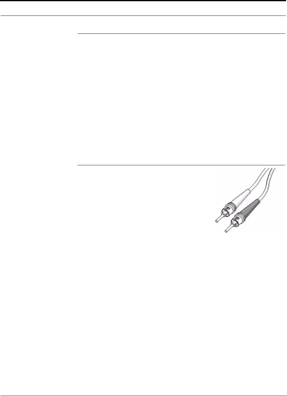
Cables and Connectors
A-2 LGCell 4.0 Installation, Operation, and Reference Manual PN 8100-40
620004-0 Rev. E
A.1 Coaxial Cable
For Duplex RF Connections
• Connects a Main Hub to a repeater or duplex base station
• Provides bidirectional downlink and uplink transmission with one cable for duplex
RF connections
For Simplex RF Connections
• Connects a Main Hub to a repeater or simplex base station
• Provides unidirectional downlink and uplink signals on separate cables for simplex
RF connections
A.2 Multimode Fiber Cable
• Connects Main Hub to Expansion Hub(s)
• Transmits (downlink) and receives (uplink) cellular
and PCS signals
• Accommodates distances up to 1 km (3300 ft)
• Use industry-standard 62.5µm/125µm fiber
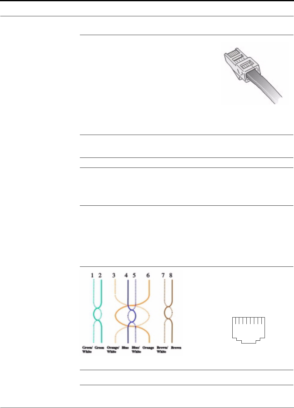
PN 8100-40 LGCell 4.0 Installation, Operation, and Reference Manual A-3
620004-0 Rev. E
Category 5 UTP/STP Cable
A.3 Category 5 UTP/STP Cable
• Connects the Expansion Hub to the RAU(s)
• Transmits (downlink) and receives (uplink) cellular
and PCS signals
• Delivers electrical power to RAU(s)
• Accommodates distances up to 50 meters (165 ft)
• Cat-5 STP is recommended when configuring mul-
tiple systems
LGC Wireless recommends plenum-rated Cat-5 UTP/STP cable and connectors
NOTE: Only Cat-5 shielded twisted pair (STP) cable should be used for neutral host
systems.
NOTE: UTP/STP cable length is 10 meters (33 ft) absolute minimum, 20 meters (66
ft) recommended minimum, and 50 meters (165 ft) maximum. For cables longer than
50 meters (165 ft), system specifications are slightly degraded. See Section 7.3.2, “Sys-
tem Gain (Loss) Relative to UTP/STP Cable Length,” on page 7-27.
UTP Termination
All UTP cable shall be terminated according to the TIA/EIA 568-A standard. The fol-
lowing diagram shows the top view of the wiring map for Category 5 UTP cable and
how the four pairs should be terminated.
Figure A-1 Wiring Map for Cat-5 UTP Cable
NOTE: Be sure to test cable termination before installing the cable.
RJ-45 Port
12345678
W-G
G
W-O
BL
W-BL
O
W-BR
BR
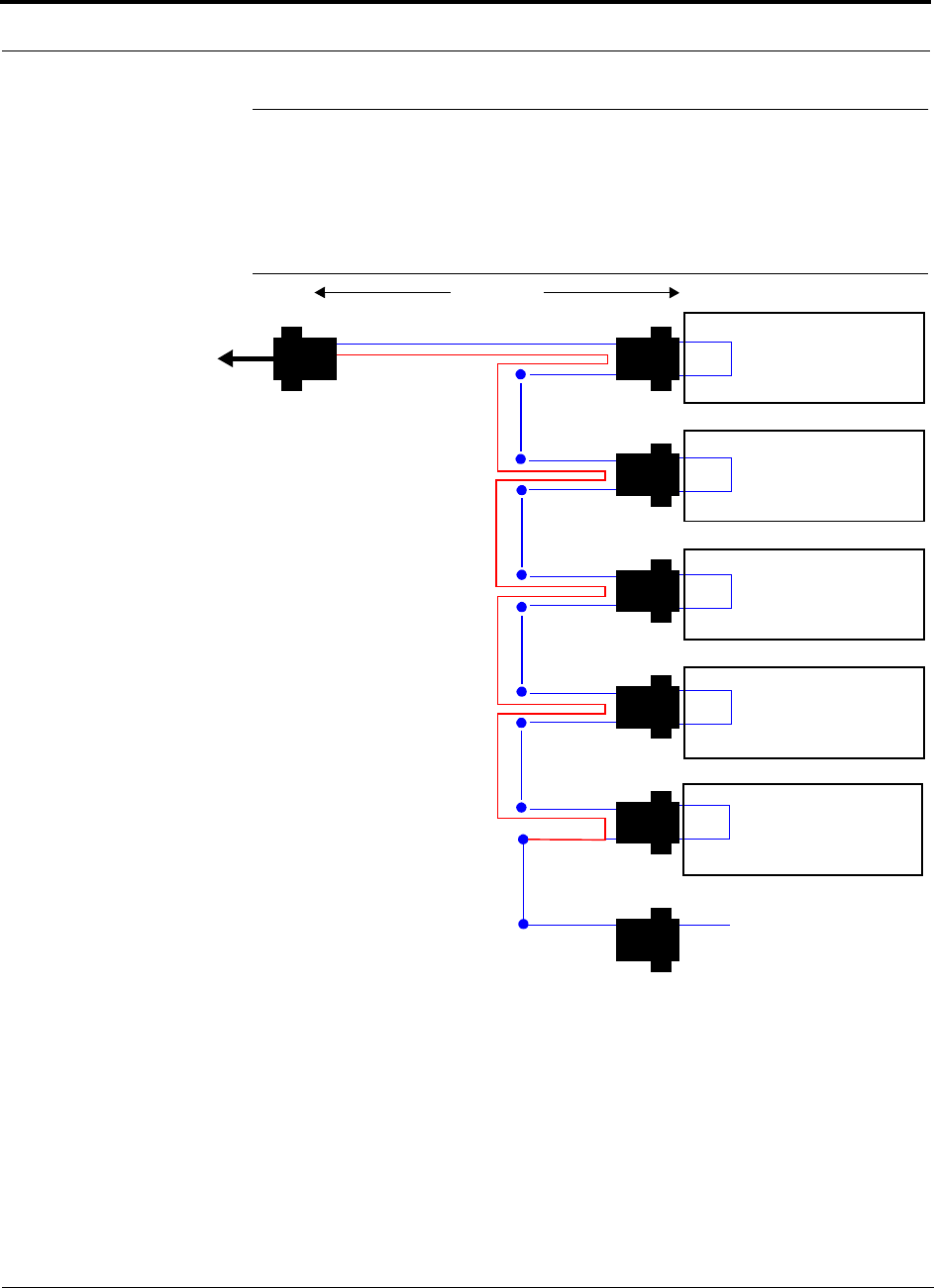
Cables and Connectors
A-4 LGCell 4.0 Installation, Operation, and Reference Manual PN 8100-40
620004-0 Rev. E
A.4 5-port Daisy-Chain Alarm Cable
Use the 5-port Daisy-Chain Alarm Cable (PN 4022-5), shown in Figure , to increase
the number of LGCells that are reporting their alarms to the base station.
Figure A-2 5-port Daisy-Chain Alarm Cable
Pin 7
Pin 9
X
1 meter (3 feet)
Pins 7 and 9
J2
Pin 7
Pin 9
X
J3
Pin 7
Pin 9
X
J4
Pin 7
Pin 9
X
J5
Pin 7
Pin 9
X
J6J7
DB-9 male
Pins 7 and 9
DB-9 male
Pins 7 and 9
DB-9 male
Pins 7 and 9
DB-9 male
Pins 7 and 9
DB-9 male
Pin 7
DB-9 female
J1
7
9
Pin 7
Option 1: Connect 5 units to cable using J2
through J6; J7 is unused.
OR
Option 2: Connect four units to first cable
using J2 through J5, connect J6 to an addi-
tional daisy-chain cable’s J1 connector; J7
is unused.
OR
Option 3: Connect fewer than four units to
cable and terminate the circuit by connect-
ing the J7 connector into the lowest num-
bered unused male connector.
LGCell Main Hub
Base Station
DIAGNOSTIC 1 Port
(an adapter
cable may be
required)
LGCell Main Hub
DIAGNOSTIC 1 Port
LGCell Main Hub
DIAGNOSTIC 1 Port
LGCell Main Hub
DIAGNOSTIC 1 Port
LGCell Main Hub
DIAGNOSTIC 1 Port

PN 8100-40 LGCell 4.0 Installation, Operation, and Reference Manual B-1
620004-0 Rev. E
APPENDIX B Compliance Information
All LGCell systems comply with Optical Fiber Safety Standard IEC/EN60825-2. The
LGCell distributed antenna system uses light emitting diodes (LEDs) and is rated as a
Class 1 optical hazard system. It has an absolute maximum output power of
–11.5 dBm at 1310 nanometers (nm). There are no restrictions on the location or use
of an LGCell system. No special precautions are required if standard work practices
are followed. Additional information on the safe use of optical fiber communications
systems is at the end of this appendix.
B.1 LGCell System Approval Status
Appendix B.1.1 through B.1.7 provide LGC Wireless’ LGCell system approval status
for various countries around the world. Some European countries require National
Type Approval to their national standards (such as Germany).
B.1.1 800 MHz Cellular
Telecom: FCC ID: NOO-DAS8-4-W
Hong Kong: Approval number: RF200110, based on the above FCC
approval
EMC: FCC Class A, Part 15, Subpart B
Safety: UL 1950 3rd edition and the cUL mark for Canada
NEBS: This is a customer driven conformance certification and typically desired
of equipment that is intended to be installed in a Central Office environ-
ment. LGC products are intended as Customer Premise Equipment and it
is not anticipated that they will be installed in a Central Office environ-
ment, therefore NEBS conformance certification has not been pursued at
this time.

Compliance Information
B-2 LGCell 4.0 Installation, Operation, and Reference Manual PN 8100-40
620004-0 Rev. E
B.1.2 800 MHz iDEN
Telecom: FCC ID: NOO-DAS8M-4IDEN-W
EMC: FCC Class A, Part 15, Subpart B
Safety: UL 1950 3rd edition and the cUL mark for Canada
NEBS: This is a customer driven conformance certification and typically desired
of equipment that is intended to be installed in a Central Office environ-
ment. LGC products are intended as Customer Premise Equipment and it
is not anticipated that they will be installed in a Central Office environ-
ment, therefore NEBS conformance certification has not been pursued at
this time.
B.1.3 900 MHz EGSM/GSM
Telecom: FCC ID: LGCell 900 EGSM: NOODAS9M-4E-W
FCC ID: LGCell 900 GSM: NOODAS9M-2-W
Germany: Approval Number A200394M (BAPT 222 ZV 15/ETS
300 609-4)
UK: Approval Number BPS091 ETS 300 609-4 March 1999
Hong Kong: Approval Number RF 200066; approval based on the above
UK approval
China: Approval Number (CMIIID): 2000CJ0457
Singapore: Approval Number PRNEQ-0417-2000, Issued to “Roots Com-
munications Pte. Ltd.”
EMC: ETS 300 342-3, October 1999
Safety: UL 1950 3rd edition and power supplies, Astec International Ltd., Model
LPS43, Universal Micro Electronics Co. Ltd., Model UPO651S-02, and
International Power Sources, Inc., Model UPO651S-02 all have CB
scheme certifications
B.1.4 1800 MHz GSM
Telecom: ETS 300 609-4, October 1998
Hong Kong: Approval Number RF 200111, approval based on European
Approval ETS 300 609-4
China: Approval Number 2000CJ0525
Singapore: Approval Number PRNEQ-0418-2000, Issued to “Roots Com-
munications Pte. Ltd.”
EMC: EN 300 339, June 1998
Safety: Power Supplies, Astec International Ltd., Model LPS 43, Universal Micro
Electronics Co. Ltd., Model UPO651S-02, and International Power
Sources, Inc., Model UPO651S-02 all have CB scheme certifications.
Markings: The UK approval number and the CE mark are required.

PN 8100-40 LGCell 4.0 Installation, Operation, and Reference Manual B-3
620004-0 Rev. E
LGCell System Approval Status
B.1.5 1900 MHz PCS
Telecom: FCC: NOO-DAS19-4-X (FCC Part 24E) Distributed Antenna System
(Repeater)
Canada: 3077331163A for the “PCS 1900” (RSS-133, Issue 1)
EMC: FCC: Class A, Part 15, Subpart B
Industry Canada: Same as FCC
Safety: UL 1950, 3rd Edition and the cUL mark for the Canadian equivalent.
NEBS: This is a customer driven conformance certification and typically desired
of equipment that is intended to be installed in a Central Office environ-
ment. LGC products are intended as Customer Premise Equipment and it
is not anticipated that they will be installed in a Central Office environ-
ment, therefore NEBS conformance certification has not been pursued at
this time.
Markings: The FCC approval number and the FCC logo are required. The word Can-
ada followed by the Canadian approval number is required. The UL mark
is required.
B.1.6 FCC Regulatory Notice
This device complies with Part 15 of the FCC Rules. Operation is subject to the fol-
lowing two conditions:
• This device may not cause harmful interference.
• This device must accept any interference received, including interference that may
cause undesired operation.
B.1.7 Industry Canada Regulatory Notice
This Class B (or Class A, if so indicated on the registration label) digital apparatus
meets the requirements of the Canadian Interference-Causing Equipment Regula-
tions.
Cet appareil numerique de la Classe B (ou Classe A, si ainsi indique sur l’etiquette
d’enregistration) respecte toutes les exigences du Reglement sur le Materiel Brouil-
leur du Canada.

Compliance Information
B-4 LGCell 4.0 Installation, Operation, and Reference Manual PN 8100-40
620004-0 Rev. E
B.2 Declaration of Conformity to Type
DECLARATION OF CONFORMITY
We, LGC Wireless, of 2540 Junction Ave., San Jose, California, 95134-1902, declare under our
sole responsibility that the product:
LGCell, EGSM/GSM 900 Repeater, Model DAS9M-4E-W, to which this declaration relates, is in
conformity with the following standards and/or other normative documents.
ETS 300 342-3, October 1999
ETS 300 609-4, March 1999
BAPT 222 ZV 15
We hereby declare that all essential radio test suites have been carried out and that the above named
product is in conformity to all the essential requirements of Directive 1999/5/EC.
The conformity assessment procedure referred to in Article 10 and detailed in Annex IV of Direc-
tive 1999/5/EC has been followed with the involvement of the following Notified Body:
BABT, Claremont House, 34 Molesey Road, Walton-on-Thames, KT12 4RQ, UK
Identification Mark: 168
The technical documentation relevant to the above equipment will be held at:
LGC Wireless, UK
G10 Regus House, Cambourne Business
Park, Cambourne, Cambridge
United Kingdom, CB3 6DP
John Dorsey
RF Approvals Engineer
March 14, 2001
Signature Date
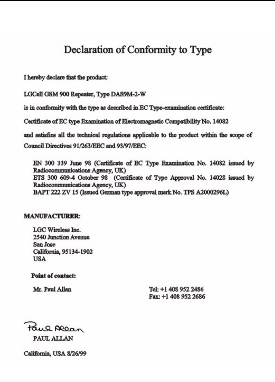
PN 8100-40 LGCell 4.0 Installation, Operation, and Reference Manual B-5
620004-0 Rev. E
Declaration of Conformity to Type

Compliance Information
B-6 LGCell 4.0 Installation, Operation, and Reference Manual PN 8100-40
620004-0 Rev. E
DECLARATION OF CONFORMITY
We, LGC Wireless, of 2540 Junction Ave., San Jose, California, 95134-1902, declare under our
sole responsibility that the product:
LGCell, DCS 1800 Repeater, Model DAS18M-2, to which this declaration relates, is in conformity
with the following standards and/or other normative documents.
EN 300 339, June 1998
ETS 300 609-4, October 1998
BAPT 222 ZV 15
We hereby declare that all essential radio test suites have been carried out and that the above named
product is in conformity to all the essential requirements of Directive 1999/5/EC.
The conformity assessment procedure referred to in Article 10 and detailed in Annex IV of Direc-
tive 1999/5/EC has been followed with the involvement of the following Notified Body:
BABT, Claremont House, 34 Molesey Road, Walton-on-Thames, KT12 4RQ, UK
Identification Mark: 168
The technical documentation relevant to the above equipment will be held at:
LGC Wireless, UK
G10 Regus House, Cambourne Business
Park, Cambourne, Cambridge
United Kingdom, CB3 6DP
John Dorsey
RF Approvals Engineer
March 14, 2001
Signature Date

PN 8100-40 LGCell 4.0 Installation, Operation, and Reference Manual B-7
620004-0 Rev. E
IEC/EN 60825-2: Safe Use of Optical Fiber Communication Systems
B.3 IEC/EN 60825-2: Safe Use of Optical Fiber
Communication Systems
Part 2 of IEC 60825 provides requirements and specific guidance for the safe use of
optical fiber communications where optical power may be accessible at some dis-
tance from the optical source. In this part of IEC 825, light emitting diodes (LEDs)
are included whenever the word “laser” is used.
B.3.1 Description of LGCell System
The LGCell is a distributed antenna system. It consists of three main components. A
Main Hub, which is connected by multimode fiber optic cables to one or more Expan-
sion Hubs. Each Expansion Hub is connected by UTP Cat-5 cable to up to four
Remote Access Units. Because LEDs are used to send a signal over the fiber optic
cable, the LGCell is covered under the IEC 60825 specification.
B.3.2 Requirements under IEC 60825
Under IEC 60825, LGC Wireless is required to determine the Class of operation of
the LGCell system, the hazard level of the LGCell system and any special instruc-
tions that must be included in an operators manual as well as any warning labels that
may be required on the LGCell system.
The LGCell is covered only under these definitions of section 3 of
60825:
•3.2 Enclosed System: A system in which, during normal operation, the optical
radiation is totally enclosed, by light-proof cabinets, components, total internal
reflection or optical fiber cables and connectors.
•3.3 End User: The person or organization using the optical fiber communication
in the manner the system was designed to be used. The user cannot necessarily
control the power generated and transmitted within the system.
•3.4 Hazard Level 1: A hazard level 1 is allocated to any part within an optical
fiber communication system at which, under reasonably foreseeable circum-
stances, human access to laser radiation in excess of the accessible emission limits
(AEL) of class 1 for the applicable wavelengths and emission duration will not
occur.
•3.10 Light Emitting Diode (LED): Any semiconductor device which can be made
to produce electromagnetic optical radiation in the wavelength range from 180nm
to 1mm. (The optical radiation is produced by the process of spontaneous emis-
sion, although some stimulated emission may be present.)
•3.13 Location with Controlled Access: A location where access to the protective
housing (enclosure) is controlled and is accessible only to authorized persons who

Compliance Information
B-8 LGCell 4.0 Installation, Operation, and Reference Manual PN 8100-40
620004-0 Rev. E
have received adequate training in laser safety and servicing of the system
involved. Examples include optical cable ducts and switching centers.
•3.14 Location with Restricted Access: A location where access to the protective
housing is restricted and not open to the public. Examples include industrial and
commercial premises, PBX rooms, computer system rooms, and optical test sets.
Distributed fiber networks may pass through unrestricted public areas, restricted
areas within premises, as well as controlled areas or they may be deployed entirely
within restricted business premises.
•3.18 Optical Fiber Communication System: An engineered assembly for the
generation, transference, and reception of optical radiation arising from lasers in
which the transference is by means of optical fiber for communication purposes.
•3.19 Reasonable Foreseeable Event: An event, the occurrence of which under
given circumstances can be predicted fairly accurately, and the occurrence of
which is a possibility. Examples of reasonably foreseeable events might include
the following: fiber cable break, optical connector disconnection, operator error or
inattention to safe working practices. Reckless use or use for completely inappro-
priate purposes is not to be considered as a reasonably foreseeable event.
B.3.3 Installation Notes
The LGCell is covered under these parts of section 5 of 60825:
•5.2.1.3 Test Equipment: During installation or testing of an optical fiber cable or
system, only test equipment of laser Class 1 should be used.
•5.2.1.5 Installation Rules: Each person engaged in the installation or service of an
optical fiber cable communication system should observe all rules, procedures, and
practices established for the safe operation of optical fiber communication sys-
tems.
B.3.4 Evaluation of LGC System
The LGCell is covered under Annex A of 60825.
The LGCell system is a self-contained product that contains an optical fiber commu-
nication system that would be safe under normal operating conditions because the
optical radiation is totally enclosed and contained under intended operation. How-
ever, because of the extended nature of the system, the optical power may be accessi-
ble a kilometer from the optical source. The LGCell system contains LEDs, which are
the source of radiation covered under IEC 825. Usually a whole fiber optical commu-
nication system would not be classified under IEC 825-2 in the same way required
under IEC 825-1. This is because, under intended operation, the optical power is
totally enclosed, and it could be argued that an interpretation of IEC 825-1 would
give a class 1 to all systems, which may not accurately reflect the hazard potential of
some systems. If the emitter can be operated separately, it should be classified accord-

PN 8100-40 LGCell 4.0 Installation, Operation, and Reference Manual B-9
620004-0 Rev. E
IEC/EN 60825-2: Safe Use of Optical Fiber Communication Systems
ing to IEC 825-1. However, the power output level of the LGCell system is so low
that it always falls into the class 1 hazard level even under 100% modulation condi-
tions. The absolute maximum allowed at 1300nm is +9.5 dBm. The absolute maxi-
mum accessible output of the LGCell fiber optic system is –11.5 dBm. Therefore
there is no restriction as to location of use of the LGCell system and there is no label-
ing requirement.
B.3.5 Suggested Work Practices
The LGCell is covered under these parts of section D7 of 60825
The following working practices are suggested for working on the LGCell system:
•Viewing Fiber: Do not stare with unprotected eyes at the connector ends of the
fibers or the ports of the hub.
•Test Fibers Cables: When using test fiber optical cables, the optical power source
shall be the last to be connected and the first to be disconnected.
•Fiber ends: Any unconnected fiber ends should be covered with an approved cap.
Do not use tape.
•Broken Fiber Cables: Do not stare with unprotected eyes at any broken ends of
the fibers. Report and have any broken fiber cables replaced.
•Cleaning: Use only approved methods for cleaning optical fiber connectors.
•Modification: Do not make any unauthorized modifications to this fiber optical
system of associated equipment.
•Live work: Live work is permitted on the LGCell as it is a class 1 hazard.
•Signs: No warning signs are required.
•Test Equipment: Use class 1 test equipment.
B.4 Human Exposure to RF
The following precautions apply to LGCell products.
• LGCell has no user-serviceable parts. Faulty or failed units are fully
replaceable through LGC Wireless. Please contact us at 1-800-530-9960. For
international customers, please contact us at +1-408-952-2400.
•Never input an RF signal to the Main Hub Duplex port that is higher than those
defined on page17 in Section 2, LGCell Equipment.
•Although modeled after an Ethernet/LAN-like architecture and connectivity,
LGCell units (Main Hub, Expansion Hub, and the Remote Antenna Unit) are
not intended to connect to Ethernet data hubs, routers, cards or other similar
data equipment.
•For improved air circulation, be sure to leave at least one inch (25 mm) of
space between all hubs and between any other equipment in the rack. If
mounting a hub on the rack’s bottom shelf, also leave at least a one inch of
clearance from the bottom.
•When you connect the Multi-Mode Fiber (MMF) Optical Cable, take the same
precaution as if installing Ethernet network equipment. All optical fiber ST
connectors should be cleaned according to the cable manufacturer’s
instructions.
•When you connect a radiating antenna to an RAU, DO NOT over-tighten the
SMA connector. Firmly hand-tightening the connector is adequate.
Antenna gain is restricted to 1.5 W ERP (2.49 W EIRP) in order to
satisfy RF exposure compliance requirements. If higher than 1.5 W
ERP, routine MPE evaluation is needed. The antennas should be
installed to provide at least 20 cm from all persons to satisfy MPE
requirements of FCC Part 2, 2.1091.
To reduce the risk of fire or electric shock, do not expose this
equipment to rain or moisture.
Fiber Port Safety Precautions
Suggested safety precautions for working with LGCell Fiber Ports follow. For
information about LGCell compliance with safety standards, see Appendix C –
Compliance Information.
•Viewing fiber: Observe the following warning about viewing fiber ends in

iv
ports.
Do not stare with unprotected eyes at the connector ends of the fibers
or the ports of the hubs.Invisible infrared radiation is present at the
front panel of the Main Hub and Expansion Hub. Do not remove the
Fiber Port dust cover unless the port is in use. Do not stare directly
into a Fiber Port.
•Test fiber cables: When you use test fiber optical cables, connect the optical
power source last and disconnect it first.
•Fiber ends: Cover any unconnected fiber ends with an approved cap. Do not
use tape.
•Broken fiber cables: Do not stare with unprotected eyes at any broken ends of
the fibers. Report any broken fiber cables and have them replaced.
•Cleaning: Use only approved methods for cleaning optical fiber connectors.
•Modifications: Do not make any unauthorized modifications to this fiber
optical system or associated equipment.
•Live work: Live work is permitted on the LGCell as it is a Class 1 hazard.
•Signs: No warning signs are required.
•Test equipment: Use Class 1 test equipment.

PN 8100-40 LGCell 4.0 Installation, Operation, and Reference Manual C-1
620004-0 Rev. E
APPENDIX C Frequently Asked Questions
• What is the LGCell Distributed Antenna System?
The LGCell Distributed Antenna System (DAS) contains multiple low-power radi-
ating elements that are deployed around indoor facilities to improve coverage and
capacity. The unique, patented architecture of the LGCell DAS provides an inex-
pensive solution to the wireless operator or wirless network manager for cover-
age/capacity upgrades and private microcell applications.
• What is twisted pair cable? Will it pick up spurious emissions?
Twisted pair (TP) cable is the standard cable that you find at the back of your com-
puter for the network hookup. TP cable is the most ubiquitous cable in any office
building. Furthermore, TP cable is inexpensive and easy to install. The twisting
nature of the cable creates a transmission line for efficient signal transfer and rejec-
tion of spurious emissions The LGCell uses a state-of-the-art common-mode rejec-
tion device that reduces pickup of spurious emissions on a TP cable by a factor of
10,000.
• Can a single LGCell simultaneously support multiple access standards (such as
1900 TDMA/CDMA/GSM)?
Yes. The LGCell is a frequency selective product. The LGCell system is transpar-
ent to the protocol that the base station and mobile unit use. You can view the
entire system with all the cables together as a frequency selective repeater with a
specified gain.
• What is the bandwidth of the LGCell?
LGCell passes selected frequencies to minimize amplification of unwanted signals.
Refer to the data specifications for the RF bandwidth of the system.
Another interpretation of bandwidth is the amount of data that the LGCell system
can transmit. The microcellular or macrocellular base station to which the LGCell
is connected limits the bandwidth or capacity of the LGCell, which is independent
of the wireless protocol and service. Total, composite output power and spurious
emissions are the only constraints that limit the number of channels that an RAU
can radiate. Furthermore, the LGCell system will not limit the data rate of the mod-
ulation transmitted through the system.

Frequently Asked Questions
C-2 LGCell 4.0 Installation, Operation, and Reference Manual PN 8100-40
620004-0 Rev. E
• Can the LGCell support multiband operation?
The LGCell provides a wide variety of single-band products, including the U.S.
800 MHz, European GSM 900, DCS 1800, Korean PCS 1800, U.S. PCS 1900 sys-
tems, and iDEN. You can use these systems together to provide multiband ser-
vices. In addition, LGC has dual band 800/1900, 900/1800, and 1800/1800 LGCell
systems available.
Additionally, an LGCell neutral host configuration can simultaneously support
multiple bands and protocols.
• Does the LGCell support paging applications?
Yes. The 900 MHz GSM and EGSM LGCells have been approved for paging and
two-way messaging in the U.S. and Canada. The products may be used over thier
entire operating frequency ranges for such applications.
• Can the LGCell system share the same UTP Category 5 cable with the Ethernet
network?
No. The LGCell system can use the existing unused cabling inside the building;
however, you cannot use the same cable to connect an RAU and a computer.
• What is the minimum power input to the Main Hub?
Refer to link budget calculation for the minimum acceptable power required to
provide the desired levels of RF coverage..
• What is the minimum detectable power of an RAU?
The minimum detectable power of system with 1 RAU is –114 dBm in a 30 kHz
bandwidth, –106 dBm in a 200 kHz bandwidth, and –98 dBm in a 1.25 MHz band-
width. These figures do not take into account the processing gain of different
access standards, which could decrease the minimum levels.
• What is the difference between connecting the LGCell to a roof-mounted
antenna and to a microcellular base station?
Connecting the LGCell to a roof-mounted antenna increases the coverage of the
indoor environment. Connecting the LGCell to a microcellular base station
improves both the coverage and the capacity in the building and might also provide
a private wireless office application for the customer.
• Does each Main Hub require a separate coaxial feed to the base station?
A typical RF input power per channel to the Main Hub is 0 dBm. This provides a
lot of margin (link budget margin) for interfacing with antennas through a base sta-
tion that typically has an output power of 20 dBm. Therefore, a power com-
biner/splitter might be installed between the Main Hub and the base station. This
enables one base station to connect to multiple Main Hubs.
• Can I exceed the 3 dB optical loss in the fiber?
No. Exceeding the 3 dB optical loss in the fiber will result in an unreliable link
indicated by sync alarms.

PN 8100-40 LGCell 4.0 Installation, Operation, and Reference Manual C-3
620004-0 Rev. E
• Is the multimode fiber step or graded index fiber?
Graded index.
• Can the LGCell use 50µm/125µm multimode optical fiber?
The LGCell is designed for use with 62.5µm/125µm fiber. Use of 50µm/125µm
fiber results in higher optical losses and degraded performance.
• How much space does the Main Hub and Expansion Hub use in a 19 in. rack?
Both units use 1U of rack space.
• Can I connect the LGCell alarms to a base station?
Yes. Use the major alarm contacts only. The base station supplies the return ground
and voltage.

Frequently Asked Questions
C-4 LGCell 4.0 Installation, Operation, and Reference Manual PN 8100-40
620004-0 Rev. E

PN 8100-40 LGCell 4.0 Installation, Operation, and Reference Manual D-1
620004-0 Rev. E
APPENDIX D Glossary
Air Interface A method for formatting data and voice onto radio waves. Common
air interfaces include AMPS, TDMA, CDMA, and GSM.
AIN Advanced Intelligent Network. AINs allow a wireless user to make and receive
phone calls while roaming outside the user’s “home” network. These networks,
which rely on computers and sophisticated switching techniques, also provide
many Personal Communications Service (PCS) features.
Amplitude The distance between high and low points of a waveform or signal.
AMPS Advanced Mobile Phone Service. AMPS is an analog cellular FDMA sys-
tem. It was the basis of the first commercial wireless communication system in
the U.S and has been used in more than 35 other countries worldwide.
Analog The original method of modulating radio signals so they can carry informa-
tion which involves transmitting a continuously variable signal. Amplitude Mod-
ification (AM) and Frequency Modulation (FM) are the most common methods
of analog modulation.
ANSI The American National Standards Institute. A nonprofit, privately funded
membership organization founded in 1918 that reviews and approves standards
developed by other organizations.
Antenna A device for transmitting and/or receiving signals.
Attenuation The decrease in power that occurs when any signal is transmitted.
Attenuation is measured in decibels (dB).
Backhaul A term applied to the process of carrying wireless traffic between the
MSC and the base station.
Base Station The radio transmitter/receiver that maintains communications with
mobile devices within a specific area.
BSC Base Station Controller. A GSM term referring to the device in charge of man-
aging the radio interface in a GSM system, including the allocation and release of
radio channels and hand-off of active calls within the system.

Glossary
D-2 LGCell 4.0 Installation, Operation, and Reference Manual PN 8100-40
620004-0 Rev. E
BTA Basic Trading Area. The U.S. and its territories are divided into 493 areas,
called BTAs. These BTAs are composed of a specific list of counties, based on a
system originally developed by Rand McNally. The FCC grants licenses to wire-
less operators to provide service within these BTAs and/or MTAs. (See MTA.)
BTS Base Transceiver Station. A GSM term referring to the group of network
devices that provide radio transmission and reception, including antennas.
C/I Carrier to interference ratio. The ratio of the desired signal strength to the com-
bined interference of all mobile phones using the system. Usually, the interfer-
ence of most concern is that provided by mobile phones using the same channel
in the system. These are referred to as “co-channel interferers.”
CCITT Consultative Committee on International Telephone and Telegraph. This
organization sets international communications standards. The CCITT is now
known as ITU (the parent organization).
CDMA Code Division Multiple Access. A digital wireless access technology that
uses spread-spectrum techniques. Unlike alternative systems, such as GSM, that
use time-division multiplexing (TDM), CDMA does not assign a specific fre-
quency to each user. Instead, every channel uses the full available spectrum. Indi-
vidual conversations are assigned a unique code which allows the conversation
to be spread out over multiple channels; transmitted to the far end; and re-assem-
bled for the recipient using a specific code.
CDPD Cellular Digital Packet Data. CDPD allows data transmission over the ana-
log wireless network. CDPD breaks data into packets and transmits these packets
on idle portions of the network.
Cell A cell defines a specific, physical area of coverage of a portion of a wireless
system. It is the basic “building block” of all modern wireless communications
systems.
Cell Site A term which refers to the location of the transmission equipment (e.g.,
basestation) within the cell.
CEPT Conference of European Postal and Telecommunications Administrations.
This organization’s mandate is to define pan-European wireless communications
standards. In 1982, CEPT mandated GSM as the access protocol for public wire-
less communications systems across Europe.
Channel The path along which a communications signal is transmitted. Channels
may be simplex (communication occurs in only one direction), duplex (commu-
nication occurs in both directions) or full duplex (communication occurs in both
directions simultaneously).
Circuit A communication connection between two or more points. A circuit can
transmit either voice or data.
CO Central Office. The main switching facility for a telecommunications system.

PN 8100-40 LGCell 4.0 Installation, Operation, and Reference Manual D-3
620004-0 Rev. E
CTIA Cellular Telecommunications Industry Association. The CTIA is an industry
association made up of most of the wireless carriers and other industry players. It
was formed in 1984 to promote the cellular industry and cellular technology.
D-AMPS Digital Advanced Mobile Phone Service. See IS-54.
dB Decibel. A unit for expressing the ratio of two amounts of power. It is often used
in wireless to describe the amount of power loss in a system (i.e., the ratio of
transmitted power to received power).
DCS Digital Communications System. DCS is often called “upbanded GSM” since
it is the GSM access scheme adopted to operate in the 1700–1800 MHz portion
of the spectrum.
Digital A method of storing, processing, and transmitting information by represent-
ing information as “0s” and “1s” via electrical pulses. Digital systems have
largely replaced analog systems because they can carry more data at higher speed
than analog transmission systems.
Electromagnetic Spectrum Electrical wave forms in frequency ranges as low as
535 kHz (AM radio) and as high as 29 GHz (cable TV).
ESMR Enhanced Specialized Mobile Radio. Digital mobile telephone services
offered to the public over channels previously used for two-way analog dispatch
services. ESMR provides digital mobile radio and telephone service as well as
messaging and dispatch features.
ETSI European Telecommunications Standards Institute. ETSI was established in
1988 to set standards for Europe in telecommunications, broadcasting and office
information technology.
FCC Federal Communications Commission. In the United States, the FCC is
responsible for the management and regulation of communication policy for all
public communications services, including wireless.
FDMA Frequency Division Multiple Access. A wireless access protocol that
assigns each user a specific radio channel for use. Since FDMA only supports
one user (or conversation) on each channel, it does not maximize use of the spec-
trum and is therefore largely been superseded by other access protocols (such as
CDMA, TDMA, GSM, iDEN) that support multiple users on a single channel.
Frequency Hopping A wireless signal transmission technique whereby the fre-
quency used to carry a signal is periodically changed, according to a predeter-
mined code, to another frequency.
Fixed An ITU definition for radio communications between specified fixed points.
Point-to-point high-frequency circuits and microwave links are two examples of
fixed applications.
FM Frequency Modulation. A method of transmitting information in which the fre-
quency of the carrier is modified according to a plan agreed to by the transmitter
and the receiver. FM can be either analog or digital.

Glossary
D-4 LGCell 4.0 Installation, Operation, and Reference Manual PN 8100-40
620004-0 Rev. E
Forward Channel Refers to the radio channel that sends information from the base
station to the mobile station. (See Reverse Channel.)
Frequency The number of times an electrical signal repeats an identical cycle in a
unit of time, normally one second. One Hertz (Hz) is one cycle per second.
Frequency re-use The ability to use the same frequencies repeatedly across a cellu-
lar system. Because each cell is designed to use radio frequencies only within its
boundaries, the same frequencies can be reused in other cells not far away with
little potential for interference. The reuse of frequencies is what enables a cellu-
lar system to handle a huge number of calls with a limited number of channels.
Gain The increase in power that occurs when any signal is amplified, usually
through an amplifier or antenna.
GHz Gigahertz. A measure of frequency equal to one billion hertz.
GSM Groupe Speciale Mobile (now translated in English as Global Standard for
Mobile Communications). GSM is the digital wireless standard used throughout
Europe, in much of Asia, as well as by some operators in the U.S. and South
America.
Handoff The process by which the wireless system passes a wireless phone conver-
sation from one radio frequency in one cell to another radio frequency in another
as the caller moves between two cells. In most systems today, this handoff is per-
formed so quickly that callers don’t notice.
Hertz A measurement of electromagnetic energy, equivalent to one “wave” per sec-
ond. Hertz is abbreviated as “Hz”.
iDEN Integrated Digital Enhanced Network. A TDMA-based wireless access tech-
nology that combines two-way radio, telephone, text message, and data transmis-
sion into one network. This system was developed by Motorola. In the U.S.,
iDEN is used by Nextel in its network.
IEEE The Institute of Electrical and Electronics Engineers. The world’s largest
technical professional society with members from more than 130 countries. The
IEEE works to advance the theory and practice of electrical, electronics, com-
puter engineering and computer science.
Infrastructure A term used to encompass all of the equipment, including both hard-
ware and software, used in a communications network.
IS-54 Interim Standard-54. A U.S. TDMA cellular standard that operates in the
800 MHz or 1900 MHz band. IS-54 was the first U.S. digital cellular standard. It
was adopted by the CTIA in 1990.
IS-95 Interim Standard-95. A U.S. CDMA cellular standard that operates in the
800 MHz or 1900 MHz band. This standard was developed by Qualcomm and
adopted by the CTIA in 1993.

PN 8100-40 LGCell 4.0 Installation, Operation, and Reference Manual D-5
620004-0 Rev. E
IS-136 Interim Standard-136. A U.S. TDMA cellular standard based on IS-54 that
operates in the 800 MHz or 1900 MHz band.
IS-553 Interim Standard-533. The U.S. analog cellular (AMPS) air interface stan-
dard.
ITU International Telecommunications Union. The ITU is the principal interna-
tional standards organization. It is charted by the United Nations and it estab-
lishes international regulations governing global telecommunications networks
and services. Its headquarters are in Geneva, Switzerland.
LMDS Local Multipoint Distribution Services. LMDS provides line-of-sight cover-
age over distances up to 3–5 kilometers and operates in the 28 GHz portion of the
spectrum. It can deliver high speed, high bandwidth services such as data and
video applications.
Local Loop A communication channel (usually a physical phone line) between a
subscriber’s location and the network’s Central Office.
MHz Megahertz. One million Hertz. One MHz equals one million cycles per sec-
ond.
Microcell A network cell designed to serve a smaller area than larger macrocells.
Microcells are smaller and lower powered than macrocells. As the subscriber
base increases, operators must continue to increase the number of cells in their
network to maximize channel re-use. This has led to an increasing number of
microcells being deployed in wireless networks.
Microwave Electromagnetic waves with frequencies above 1 GHz. Microwave
communications are used for line-of-sight, point-to-point, or point-to-multipoint
communications.
MSA Metropolitan Statistical Area. The FCC has established 306 MSAs in the U.S.
The MSAs represent the largest population centers in the U.S. At least two wire-
less operators are licensed in each MSA.
MSC Mobile Services Switching Center. A generic term for the main cellular
switching center in the wireless communications network.
MSS Mobile Satellite Service. Communications transmission service provided by
satellites. A single satellite can provide coverage to the entire United States.
MTA Major Trading Area. The U.S. and its territories are divided into 51 MTAs.
Each MTA is composed of a specific number of BTAs. The FCC grants licenses
to wireless operators to provide service within these MTAs and/or BTAs. (See
BTA.)
Multiplexing The simultaneous transmission of two or more signals on the same
radio (or other) transmission facility.
N-AMPS Narrowband Advanced Mobile Phone Service.

Glossary
D-6 LGCell 4.0 Installation, Operation, and Reference Manual PN 8100-40
620004-0 Rev. E
PCMCIA Personal Computer Memory Card International Association. This acro-
nym is used to refer to credit card sized packages containing memory, I/O
devices and other capabilities for use in Personal Computers, handheld comput-
ers and other devices.
PCS Personal Communications Service. A vague label applied to new-generation
mobile communication technology that uses the narrow band and broadband
spectrum recently allocated in the 1.9 GHz band.
PDA Personal Digital Assistant. Portable computing devices that are extremely por-
table and that offer a variety of wireless communication capabilities, including
paging, electronic mail, stock quotations, handwriting recognition, facsimile, cal-
endar, and other information handling capabilities.
PDC Personal Digital Cellular (formerly Japanese Digital Cellular). A
TDMA-based digital cellular standard that operates in the 1500 MHz band.
Phase The particular angle of inflection of a wave at a precise moment in time. It is
normally measured in terms of degrees.
PHS Personal Handyphone System. A wireless telephone standard, developed and
first deployed in Japan. It is a low mobility, small-cell system.
POP Short for “population”. One person equals one POP.
POTS Plain Old Telephone Service.
PSTN Public Switched Telephone Network. Refers to the international telephone
system and includes both local and long distance networks.
Reverse Channel Refers to the radio channel that sends information from a mobile
station to a base station. (See Forward Channel.)
RF Radio Frequency. Those frequencies in the electromagnetic spectrum that are
associated with radio wave propagation.
Roaming The ability to use a wireless phone to make and receive calls in places
outside one's home calling area.
RSA Rural Service Area. One of the 428 FCC-designated rural markets across the
United States used as license areas for cellular licenses. (See MTAs and BTAs.)
Sector A portion of a cell. Often, different sectors within the same cell will each use
a different set of frequencies to maximize spectrum utilization.
Signal to Noise Ratio The ratio of signal power to noise power at a given point in a
given system.
Smart Antenna Refers to an antenna whose signal handling characteristics change
as signal conditions change.
Soft Handoff Virtually undetectable by the user, soft handoff allows both the origi-
nal cell and a new cell to serve a call temporarily during the handoff transition.

PN 8100-40 LGCell 4.0 Installation, Operation, and Reference Manual D-7
620004-0 Rev. E
Spectrum The range of electromagnetic frequencies.
Spread Spectrum A method of transmitting a signal over a broad range of frequen-
cies and then re-assembling the transmission at the far end. This technique
reduces interference and increases the number of simultaneous conversations
within a given radio frequency band.
T-1 A North American commercial digital transmission standard. A T-1 connection
uses time division multiplexing to carry 24 digital voice or data channels over
copper wire.
TDMA Time Division Multiple Access. A method of digital wireless communica-
tions that allows multiple users to access (in sequence) a single radio frequency
channel without interference by allocating unique time slots to each user within
each channel.
TIA Telecommunications Industry Association.
TR-45 One of six committees of the Telecommunications Industry Association.
TR-45 oversees the standard making process for wireless telecommunications.
Upbanded A service or technology that has been re-engineered to operate at a
higher frequency than originally designed.
Wireless Describes any radio-based system that allows transmission of voice and/or
data signals through the air without a physical connection, such as a metal wire
or fiber optic cable.
Wireline Wire paths that use metallic conductors to provide electrical connections
between components of a system, such as a communication system.
WLANs Wireless Local Area Networks. Technology that provides wireless commu-
nications to Portable Computer users over short distances.

Glossary
D-8 LGCell 4.0 Installation, Operation, and Reference Manual PN 8100-40
620004-0 Rev. E