ADC Telecommunications DAS9M-2-W LGCell GSM User Manual LGCell 4 0
ADC Telecommunications Inc. LGCell GSM LGCell 4 0
UserManual.wiki
>
ADC Telecommunications
>
DAS9M-2-W User Manual
>
User Manual pt2
Contents
1.
User manual pt1
2.
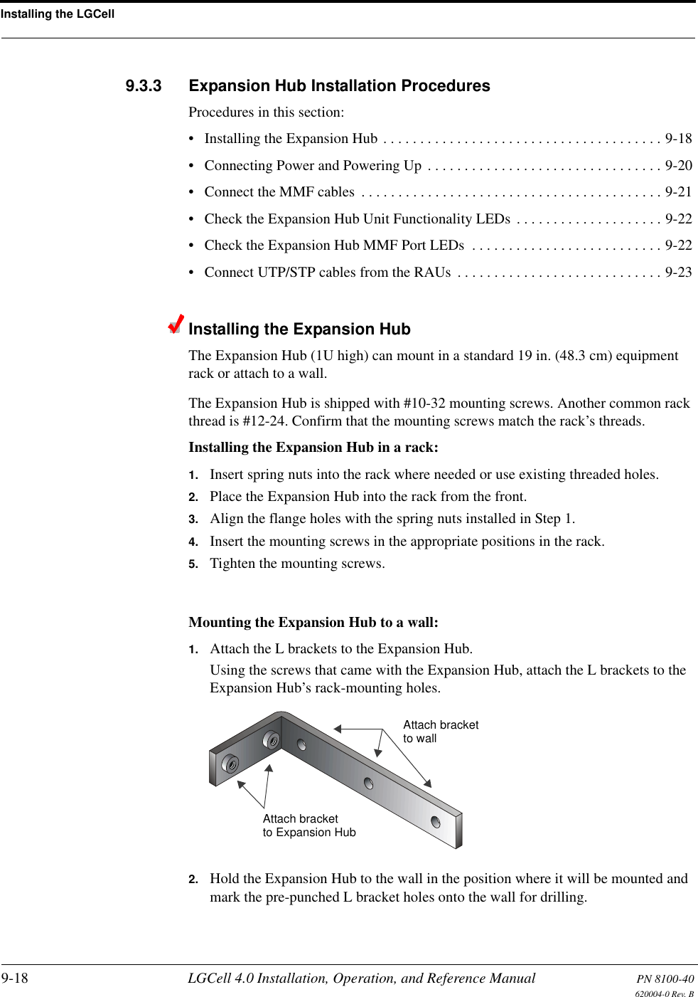
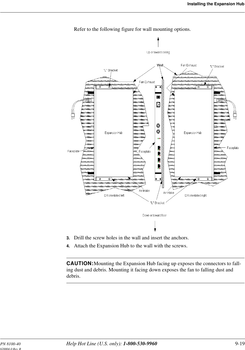
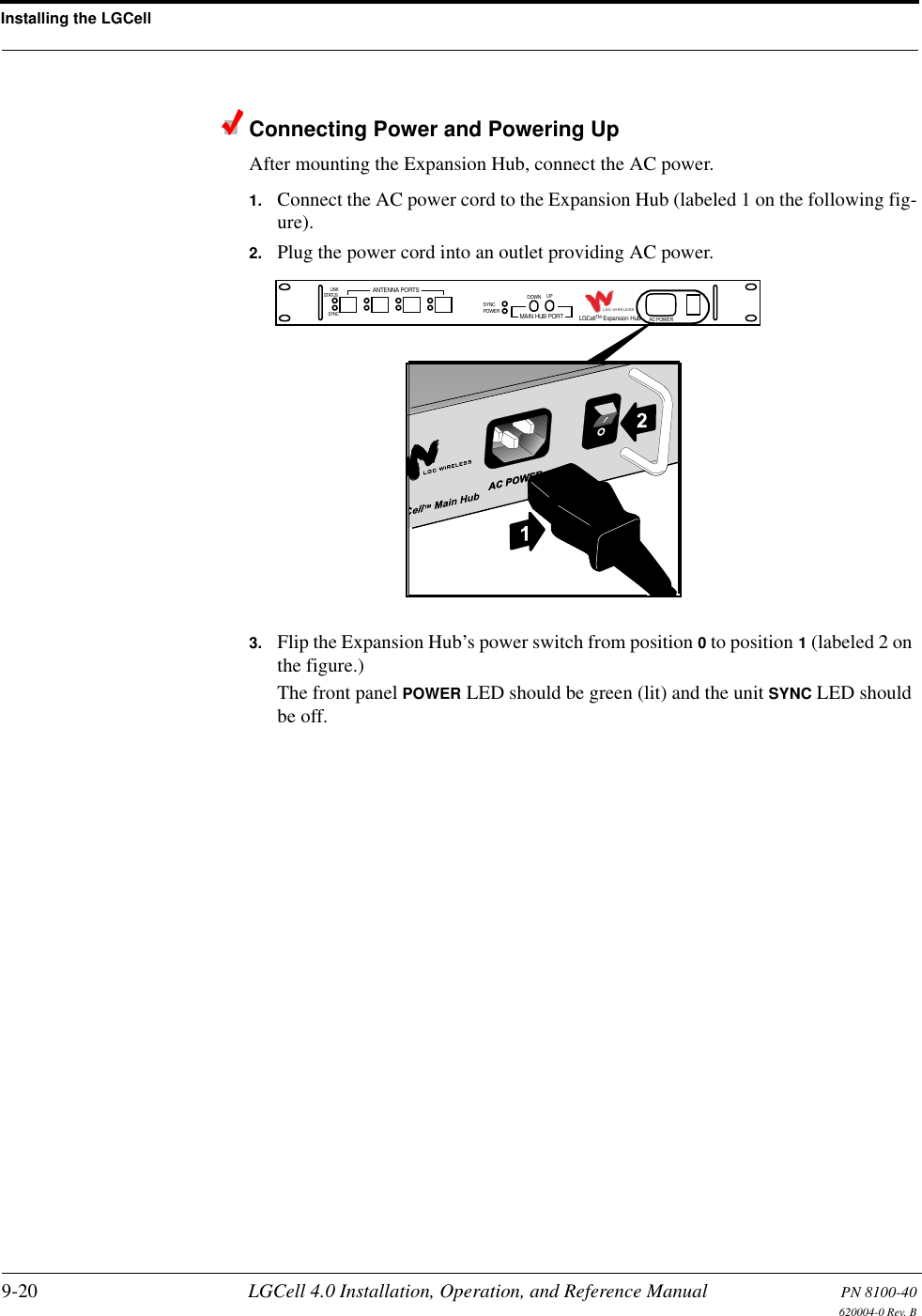
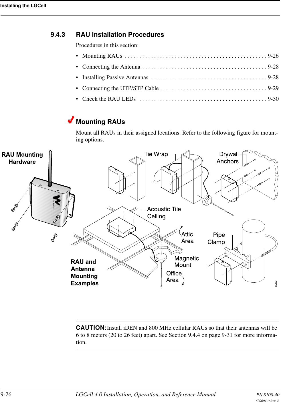
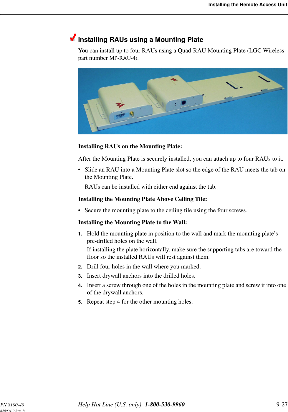
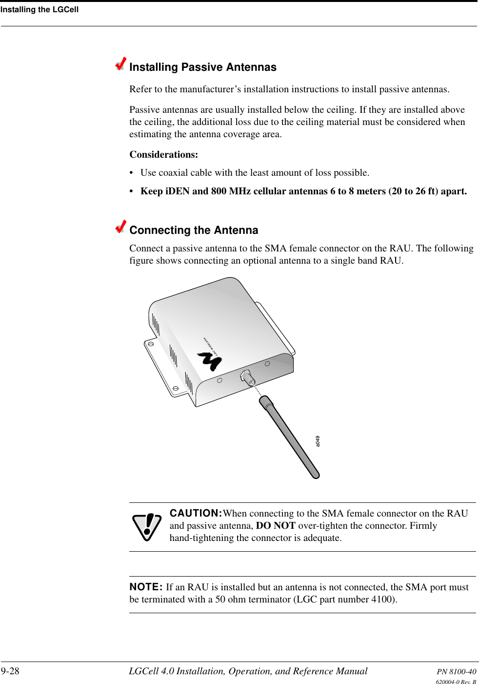
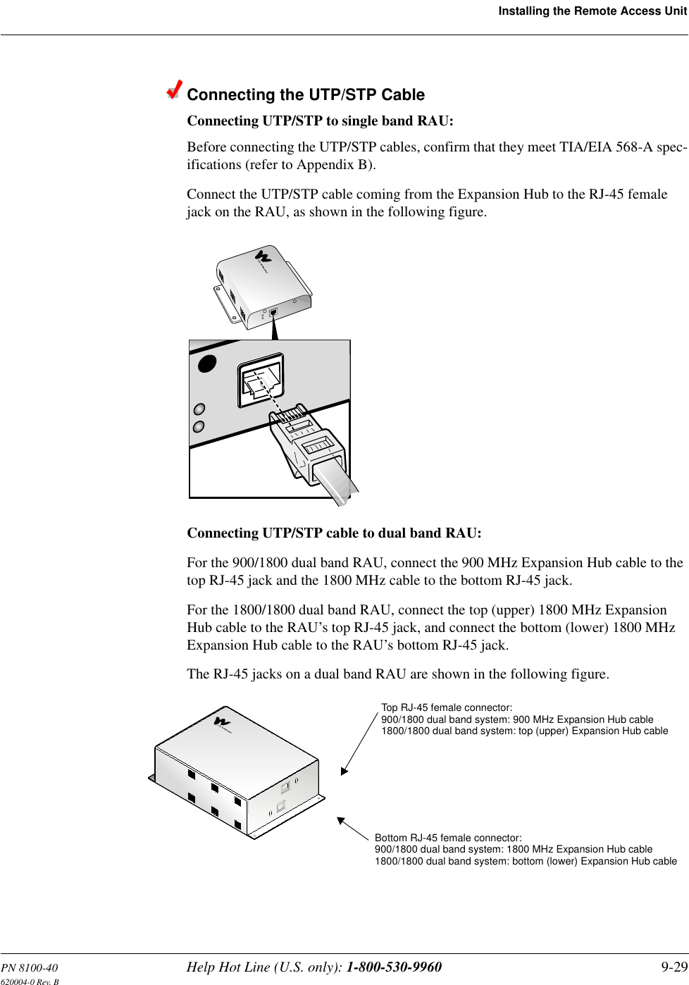
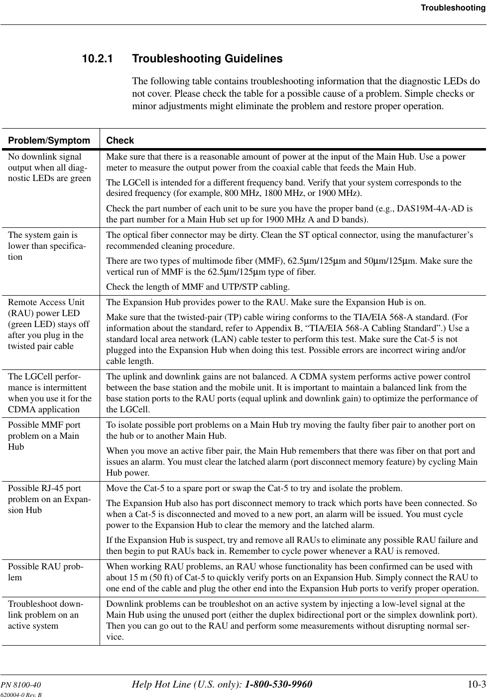
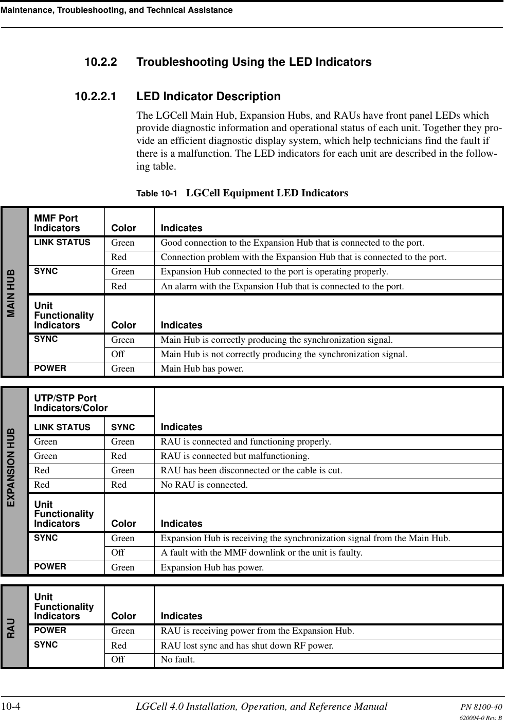
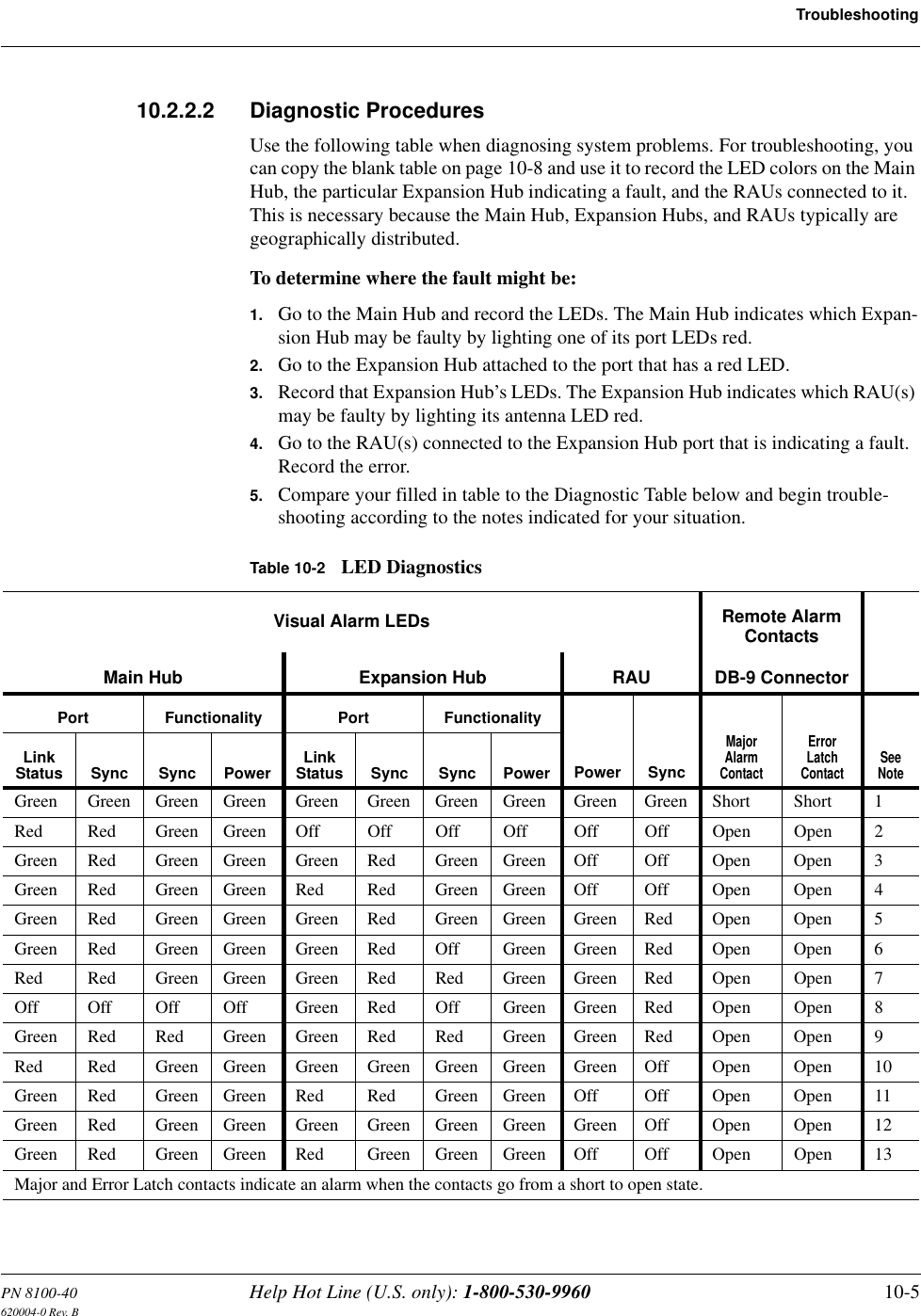
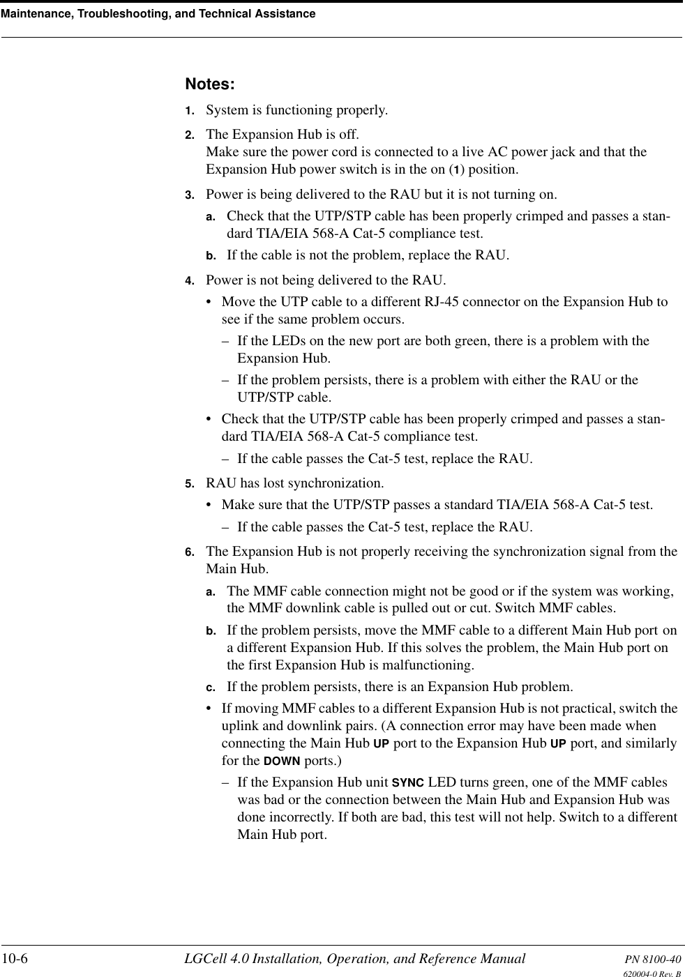
User Manual pt2
User Manual pt2
Navigation menu
Upload a User Manual
Namespaces
Wiki Guide
HTML
PDF
Info
Views
User Manual
Discussion / Help
Navigation