ADC Telecommunications DIS080AB Digivance® 800 MHz Indoor Coverage Solution User Manual 75130 CV
ADC Telecommunications Inc Digivance® 800 MHz Indoor Coverage Solution 75130 CV
Contents
- 1. Users manual 1
- 2. Users manual 2
- 3. Users manual 3
Users manual 2

ADCP-75-130 • Issue 3C • August 2006
Page 16
© 2006, ADC Telecommunications, Inc.
Table 6. Maximum Forward Path RF Output Signal Levels at the Digital Remote Unit
MODULATION GSM 800 EDGE 800 AMPS 800 TDMA 800 CDMA 800
NUMBER OF
CARRIERS
Composite
(dBm)
Per
Carrier
(dBm)
Composite
(dBm)
Per
Carrier
(dBm)
Composite
(dBm)
Per
Carrier
(dBm)
Composite
(dBm)
Per
Carrier
(dBm)
Composite
(dBm)
Per
Carrier
(dBm)
1 25.5 25.5 24.5 24.5 25 25 22 22 15 15
2 23.5 19.5 21 18 22 19 20 17 14 11
3 21 16 19 13.5 20.5 16 19 14 13.5 9
4 20 14 18 12 19 13 18 12 13 7
5 19 12 17 10 18 11 17.5 10.5 12.5 6
6 18 10 16 8.5 17.5 9.5 17 9 12 4.5
7 17.5 9 15.5 7 17 8 16.5 8 12 3.5
8 17 8 15 6 16 7 16 7 11.5 3
Note : Per Industry Canada Section 5.3 – The rated output power of this equipment is for single carrier
operation. For situations where multiple carrier operation signals are present, the rating would have to be
reduced by 3.5 dB, especially where the output signal is re-radiated and can cause interference to
adjacent band users. This power reduction is to be by means of input power or gain reduction and not by
an attenuator at the output of the device.
ADCP-75-130 • Issue 3C • August 2006
Page 17
© 2006, ADC Telecommunications, Inc.
3 INSTALLATION PLANNING AND SYSTEM DESIGN
This section provides installation planning information and basic system design recommendations
for RF engineers that will be designing and installing an in-building coverage solution using the
Digivance ICS. System design and planning services are available from ADC if required. Refer to
Section 7 of this manual for additional information.
3.1 Base Station Interface Requirements
The DHU may be interfaced either locally or remotely with the BTS. As referenced in this
publication, the BTS could be either a microcell or a cell site base station. With a local
interface, a hard-wire connection is provided between the DHU and the BTS (microcell) using
coaxial cables. With a remote interface, an over-the-air connection is provided between the
DHU and the BTS (cell site base station) using a donor antenna.
3.1.1 Local BTS (Microcell) Interface
A local interface between the DHU and the BTS (microcell) over coax requires specific RF
input and output signal levels at both the DHU and BTS. The correct signal levels can
generally be provided by inserting attenuation in the forward and reverse signal paths.
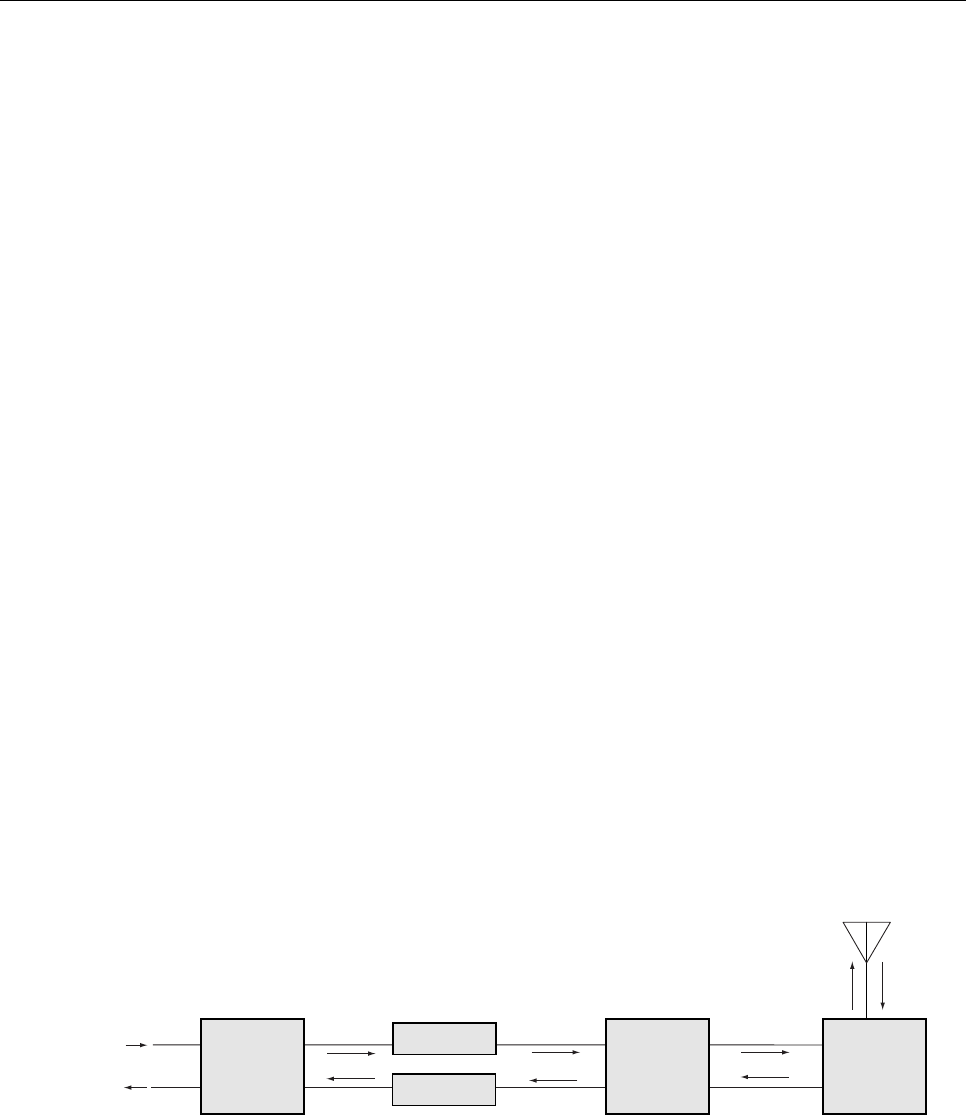
In the forward path, the correct input level can be provided at the DHU using the High Power
Conditioning Panel (HPCP). The HPCP is an accessory item that is used to attenuate the
forward path RF signal. The HPCP provides attenuation adjustments in 1 dB increments over
a range of 40 to 70 dB. A block diagram of a typical local BTS interface is shown in Figure 8.
The maximum RF input signal level the DHU will accept is determined by the DHU overdrive
limiter. When the RF signal input to the DHU is set to 1 dB below the DHU overdrive level, the
RF signal output at the DRU will be at the specified maximum level (see Table 6). The level of the
RF signal output at the DRU is dependent on the modulation protocol and the number of carriers.
HIGH POWER
COND. PANEL
FORWARD
(DOWNLINK)
REVERSE
(UPLINK)
COMPOSITE MAX
PER TABLE 6
-40 dBm
(COMPOSITE
MAX)
COMPOSITE
MAX PER
ADJUSTMENT
PROCEDURE
-30 dBm
(COMPOSITE
MAX) 17792-C
DIGITAL
HOST
UNIT
OPTICAL LINK
OPTICAL LINK
DIGITAL
REMOTE
UNIT
DIRECTIONAL ANTENNA
TO/FROM HANDSETS
LOCAL BASE
TRANSCEIVER
STATION
(MICRO CELL)
T1 LINK
TO SWITCH EXTERNAL
ATTENUATOR
(IF REQUIRED)
Figure 8. Local BTS Interface Block Diagram
In the reverse path, the input signal level required at the BTS can generally be provided using
an external attenuator or by adjusting the BTS. When the level of the reverse path (uplink)
signal at the DRU is at the recommended composite maximum of –40 dBm, the level of the
RF output signal from the DHU will be –30 dBm.
ADCP-75-130 • Issue 3C • August 2006
Page 18
© 2006, ADC Telecommunications, Inc.
The HPCP is rack or wall mountable. Refer to the Digivance ICS 800 and 1900 MHz High
Power Conditioning Panel User Manual (ADCP-75-175) for additional information.
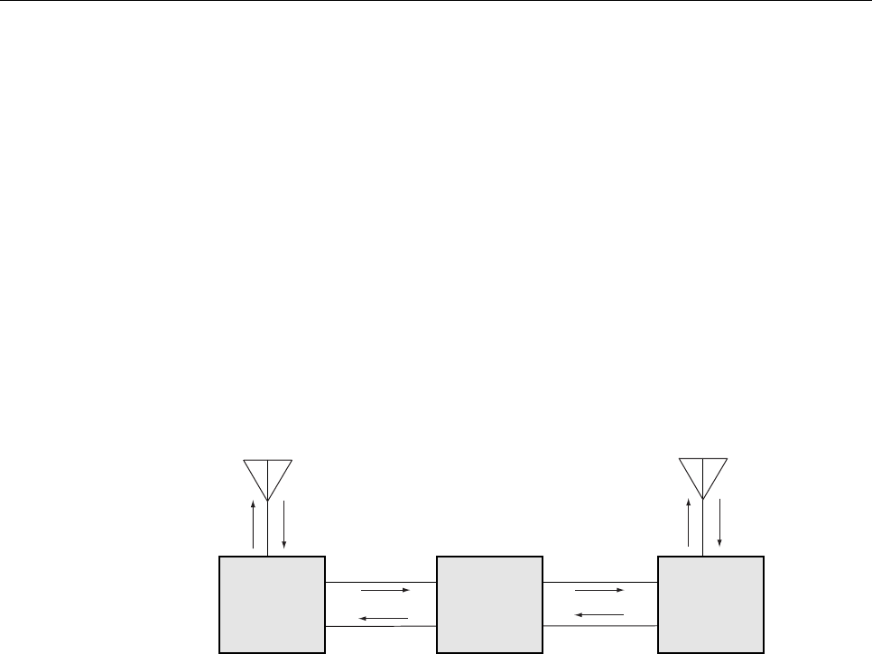
3.1.2 Remote BTS (Cell Site Base Station) Interface
A remote interface between the DHU and the BTS (cell site base station) via a donor antenna
requires specific RF input and output signal levels at both the DHU and the antenna. The
correct input and output signal levels can generally be provided using the Remote Interface
Unit (RIU). The RIU is an accessory item that is used to adjust both the forward and reverse
path RF signal levels. In the forward path, the RIU provides gain adjustments in 1 dB
increments over a range of +9 to +40 dB. In the reverse path, the RIU provides gain
adjustments in 1 dB increments over a range of +28 to +59 dB. A block diagram of a typical
remote DHU to BTS interface is shown in Figure 9.
DIRECTIONAL
ANTENNA TO/FROM
CELL SITE BTS
17793-B
REMOTE
INTERFACE
UNIT
FORWARD
(DOWNLINK)
REVERSE
(UPLINK)
-40 dBm
(COMPOSITE
MAX)
-30 dBm
(COMPOSITE
MAX)
DIGITAL
HOST
UNIT
OPTICAL LINK
OPTICAL LINK
DIGITAL
REMOTE
UNIT
DIRECTIONAL ANTENNA
TO/FROM HANDSETS
COMPOSITE MAX
PER TABLE 6
COMPOSITE
MAX PER
ADJUSTMENT
PROCEDURE
Figure 9. Remote BTS Interface Block Diagram
The RIU connects to a directional antenna through a duplexer (internal) that provides separate
forward and reverse path connections for the DHU. In the forward path (downlink), the
maximum RF input signal level the DHU will accept is determined by the DHU overdrive limiter.
When the RF signal input to the DHU is set to 1 dB below the DHU overdrive level, the RF signal
output at the DRU will be at the specified maximum level (see Table 6). The level of the RF signal
output at the DRU is dependent on the modulation protocol and the number of carriers.
In the reverse path, the RF output signal level required at the donor antenna will vary
depending on the distance from the BTS. When the level of the reverse path (uplink) signal at
the DRU is at the recommended composite maximum level of –40 dBm, the level of the RF
output signal from the DHU with be –30 dBm. Therefore, it will generally be necessary to add
some gain to the reverse path signal in order to provide the output RF signal level required at
the donor antenna.
The RIU is rack or wall mountable and is powered by 120–240 VAC (50/60 Hz) power. Refer
to the Digivance Remote Interface Unit User Manual (ADCP-75-178) for additional
information.

ADCP-75-130 • Issue 3C • August 2006
Page 19
© 2006, ADC Telecommunications, Inc.
3.2 Location and Mounting Requirements
3.2.1 DHU and DEU Location and Mounting Requirements
The DHU and the DEU may be either rack mounted or wall mounted. Fasteners (both metric and
US standard) are included with each unit for rack mount applications. A pair of reversible mounting
brackets is provided that allows the unit to be mounted in either a 19-inch or 23-inch EIA or WECO
equipment rack. When rack-mounted, the front panel of the unit is flush with the front of the rack.
The cable management tray extends 3.9 inches (99 mm) beyond the front panel. Both the DHU and
DEU occupy 3.5 inches (89 mm) of rack space. Make sure the mechanical loading of the rack will
be even to avoid a hazardous condition such as a severely unbalanced rack. The rack should safely
support the combined weight of all the equipment it holds and be properly anchored.
For wall-mount applications of the DHU or DEU, a pair of holes is provided in the cable
management tray that allows the unit to be mounted on any flat vertical surface. The mounting
holes are spaced 11-21/32 inches (296 mm) apart. The DHU/DEU should be oriented so the
front panel faces up when mounted. Appropriate fasteners for wall mounting must be provided
by the installer. It is recommended that a backer board such as 3/4-inch plywood be installed
over the mounting surface to provide a secure base for attaching the DHU or DEU.
The DHU and DEU should be mounted in a non-condensing indoor environment such as
inside a wiring closet or within an environmentally controlled cabinet. All controls,
connectors, and indicators are mounted on the front panel. All cables should be routed to the
front panel for connection. Cable retainers provided on the cable management tray for
securing the fiber optic, DC power, and external alarm system cables.
The maximum recommended ambient temperature for the DHU and DEU is 50º C (122º F).
Sufficient space for air circulation should be provided between each unit when installed in a
multi-unit rack assembly because the operating ambient temperature of the rack environment
might be greater than room ambient. A minimum clearance of 3 inches (76 mm) should be
provided on both the left and right sides of the unit for air intake and exhaust. Refer to Figure
2 for the DHU dimensions and Figure 6 for the DEU dimensions.
3.2.2 DRU Location and Mounting Requirements
The DRU must be installed in a non-condensing indoor environment and may be wall-mounted
or ceiling-mounted. The DRU may also be installed in spaces used for environmental air such
as the space over a suspended ceiling or beneath a raised floor. However, the DRU is not
intended for installation in marine, industrial, or Intrinsic Safety (IS) environments without an
engineering review of the air quality as well as other constituent gasses and dusts. Indoor air
environments are to have air borne contaminants at or below levels established in Telcordia
Standard, GR-63-CORE, Network Equipment-Building System (NEBS) Requirements:
Physical Protection, Section 4.5 Airborne Contaminants, Table 4-11, Indoor Contaminant
Levels. Contact ADC for application assistance if necessary.
The DRU is equipped with four integral mounting feet that allow it to be fastened to any flat
vertical or horizontal surface. Holes are provided in the mounting feet for inserting fasteners.
Appropriate fasteners for securing the DRU to the selected mounting surface must be provided
by the installer.

ADCP-75-130 • Issue 3C • August 2006
Page 20
© 2006, ADC Telecommunications, Inc.
The DC power cable and optical fibers should be routed to the DRU front panel for connection.
The antenna coaxial cable should be routed to the DRU rear panel for connection. A minimum of
3 inches (76 mm) of clearance space should be provided on all sides of the DRU (except the
bottom) to ensure there is adequate air circulation for cooling. In addition, at least one surface of
the DRU installation area must be open to the interior of the building. If a portable/flexible
antenna will be installed, a minimum of 9 inches (229 mm) clearance should be allowed on the
surface that is perpendicular to the antenna. Refer to Figure 4 for the DRU dimensions.
3.3 Powering Requirements
3.3.1 DHU and DEU Powering
The DHU and DEU are powered by 120–240 VAC (50/60 Hz) which is supplied through a
standard three-conductor 120 VAC power cord. The power cord is provided with the unit and
is 98 inches (2.5 m) long. Both the DHU and the DEU have a current rating of 2.0 Amps at
120 VAC input. Each unit should be located so that an AC outlet is within the reach of the
power cord.
If back-up powering is required, it is recommended that the building Uninterruptible Power Supply
(UPS) system be used to provide back-up power to the DHU and DEU in the event of an AC power
outage. This will also power all the DRU’s that are powered by the DHU or DEU.
3.3.2 DRU Powering
The DRU is powered by 48 VDC power which is input to the DRU through the front panel RJ-
45 connector. Power to the DRU may be provided by the DHU, DEU, or by a 120 VAC to 48
VDC power converter (available separately as an accessory item) plugged into a properly
grounded 120 VAC outlet. The DRU has a current rating of 400 mA at 48 VDC input.
If the DRU will be powered by the DHU or DEU, the power cable must be fabricated on-site by the
installer. Category 3 or 5 twisted pair cable should be used for the power supply cable. The maximum
recommended length of the power cable is 500 meters. The power cable must be routed between the
DHU or DEU and the DRU. Both ends of the power cable must be terminated with a male RJ-45
connector. If the DRU will be located more than 500 meters from the DHU or DRU, it must be locally
powered by a 48 VDC power converter.
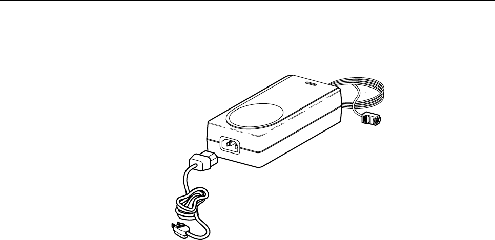
The DRU may be powered locally by the AC/DC converter, shown in Figure 10, which is
available as an accessory item. The converter is a UL Listed stand alone Limited Power
Supply (LPS) unit with a rated output of 48 VDC at 1.2 Amps. The converter is equipped
with a 6-foot (1.8 m) DC power cable which is terminated with an RJ-45 male connector. The
converter is powered by 120–240 VAC (50/60 Hz) power which is supplied though a standard
120 VAC three-conductor power cord. The power cord is 6 feet (1.8 m) long and is provided
with the converter.
ADCP-75-130 • Issue 3C • August 2006
Page 21
© 2006, ADC Telecommunications, Inc.
15988-A
Figure 10. AC/DC Power Converter
3.4 Optical Options and Requirements
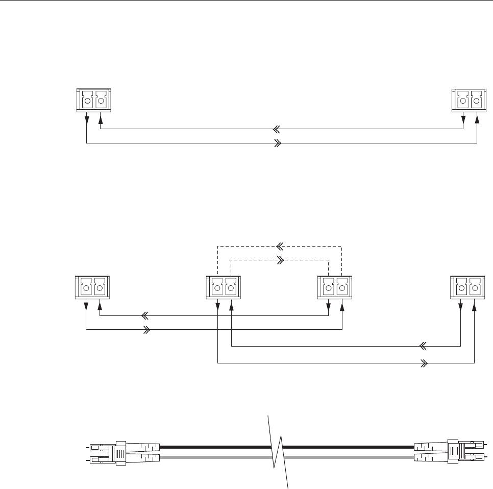
Each DHU and its associated DEU’s and DRU’s are connected over a pair of optical fibers.
One fiber transports the forward path optical signal and the other fiber transports the reverse
path optical signal. Either 62.5 or 50 micron core multi-mode optical fiber; or 9 micron core
single-mode optical fiber may be used for the optical transport connection. With 62.5 micron
core fiber, the optical path may be up to 500 meters in length. With 50 micron core fiber, the
optical path may be up to 750 meters in length. With 9 micron core cable, the optical path may
be up to 10 kilometers in length. Single- and multi-mode fibers may be used in the same
system. A diagram of the optical connections is shown in Figure 11.
Whenever possible, use conduit or a guideway such as the FiberGuide system to route the optical
fibers between the DHU, the DEU’s, and the DRU’s. Avoid routing optical fibers through ladder
type cable racks or troughs that do not provide sufficient support to limit bending or prevent
accidental damage. Tie-wrapping is not recommended as a means of securing fiber optic cables.
Provide sufficient slack at each unit for connecting each fiber to the required port. Fibers may be
pre-terminated or terminated on-site using field-installable LC type connectors.
ADCP-75-130 • Issue 3C • August 2006
Page 22
© 2006, ADC Telecommunications, Inc.
TX RX
TX RX
TX RX TX RX TX RX TX RX
PORTS 1-6
PORTS
1-6
PORTS 1-6
FIBER PORT
FIBER PORT
HOST
PORT
FORWARD PATH
REVERSE PATH
FORWARD PATH
REVERSE PATH
FORWARD PATH
REVERSE PATH
DIGITAL
REMOTE
UNIT
DIGITAL
REMOTE
UNIT
DIGITAL
HOST
UNIT
DIGITAL
HOST
UNIT
DIGITAL EXPANSION UNIT
BASIC CONFIGURATION WITH DHU AND DRU
BASIC CONFIGURATION WITH DHU, DEU, AND DRU
END-TO-END OPTICAL CONNECTOR/CABLE ASSEMBLY DIAGRAM
16814-A
62.5 MICRON: MAXIMUM LENGTH = 500 METERS
50 MICRON: MAXIMUM LENGTH = 750 METERS
9 MICRON: MAXIMUM LENGTH = 10 KILOMETERS
Figure 11. Digivance ICS Optical Connections
3.5 Coaxial Cable Requirements
The DHU interfaces either locally (see Figure 8) or remotely (see Figure 9) with the BTS
through coaxial cable connections. In a local interface, coaxial cables are required to link the
DHU, HPCP, and the BTS. In a remote interface, coaxial cables are required to link the DHU,
RIU, and the donor antenna. The DHU, HPCP, and RIU are equipped with N-type female
connectors for connecting the forward and reverse path coaxial cables. High performance,
flexible, low loss 50-ohm coaxial communications cable (RG 400 or equivalent) should be
used for all coaxial connections.

ADCP-75-130 • Issue 4A • December 2006
Page 23
© 2006, ADC Telecommunications, Inc.
3.6 System Expansion Planning
The DEU enables 6-way expansion of any optical port. This makes it possible to add more
DRU’s without having to install additional DHU’s. Each DHU is equipped with six optical
ports. If more than six DRU’s are required by the application, a DEU may be connected to one
of the optical ports at the DHU which expands that port to six ports. If still more optical ports
are required, then a second DEU may be connected to the DHU or a second DEU may be
connected to the first DEU. The ability to cascade DEU’s in parallel or in series provides
unlimited flexibility. It is physically possible to connect an unlimited number DRU’s to the
DHU through the installation of DEU’s.
The total number of DRU’s that can be served is limited by the cumulative noise effect caused
by antenna combining. This number cannot be determined until the radius distance of coverage
required at the DRU antenna is determined and the path loss attributed to the structure are
known. The system design requires that the carrier to noise differential be greater than the
customer’s desired signal to noise ratio.
If it is likely that the system will be expanded in the future, locate the DHU in such a way that it can
be used as a hub for an expanded system. It should be noted that a DEU can be used as an optical
regenerator. A DRU may sometimes need to be located at a point that is beyond the distance
limitation imposed by the optical fiber. The solution is to install a DEU at the maximum optical
fiber length from the DHU. This provides an additional 500 m, 750 m, or 10 km (depending on the
fiber type) of optical fiber length beyond the DEU for connecting the DRU.
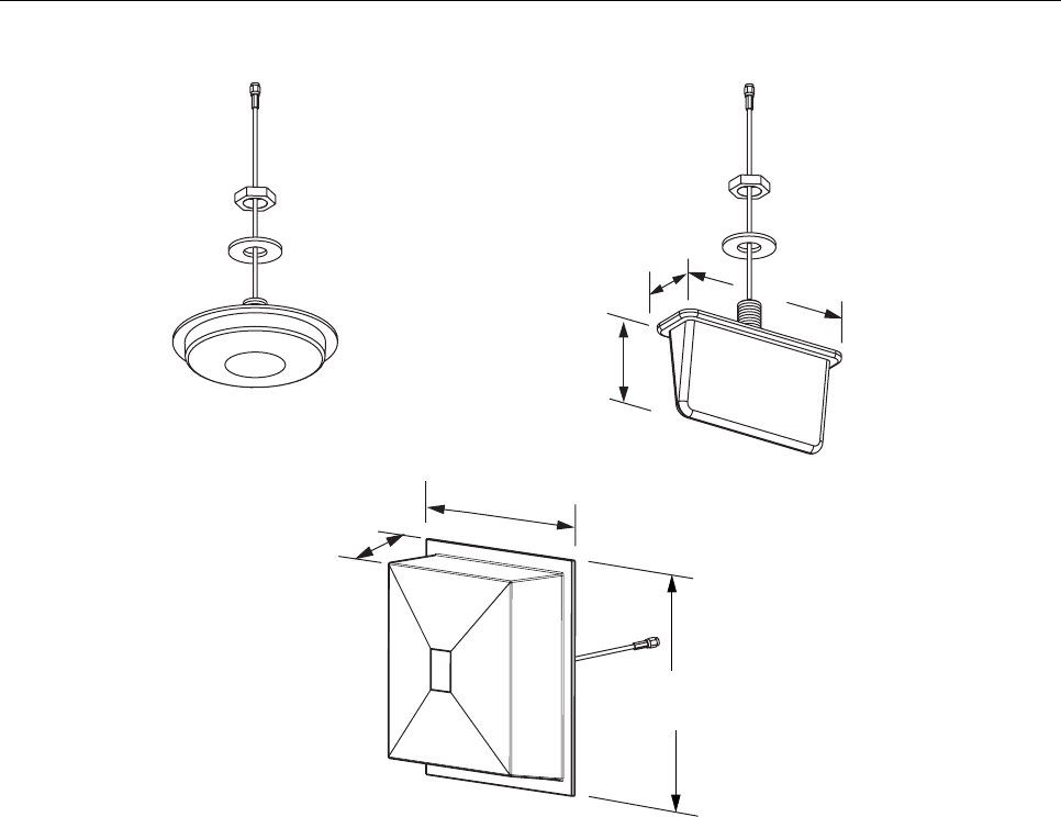
3.7 DRU Antenna Options
Various antennas, shown in Figure 12, are available from ADC for use with the DRU. All
antennas include a 6-foot (1.8 m) long 50-ohm coaxial cable (equipped with SMA male
connector) for connection to the DRU. The DRU is equipped with an SMA female connector
for connecting the antenna cable.
The DRU antennas are designed for unobtrusive mounting within an office environment. Each
type of antenna provides a specific coverage pattern in order to accommodate the shape of the
area where coverage is required. The ceiling-mount omni directional antenna is designed to
mount in the center of the coverage area. The directional panel antenna is designed to mount
vertically on one side of the coverage area or in the corner of the coverage area. The ceiling
mount hallway antenna is designed to mount in the center of long corridors. Non-ADC
antennas may also be used with the DRU to meet various application requirements but must
comply with equipment authorization for RF exposure compliance.
Note: To comply with Maximum Permissible Exposure (MPE) requirements, the maximum
composite output from the antenna cannot exceed 1000 Watts EIRP and the antenna must be
permanently installed in a fixed location that provides at least 6 meters (20 feet) of separation
from all persons.
ADCP-75-130 • Issue 3C • August 2006
Page 24
© 2006, ADC Telecommunications, Inc.
DIAMETER - 6.14 INCH (156 MM)
DEPTH - 1.05 INCH (27 MM)
7.26 INCHES
(184 MM)
3.88 INCHES
(99 MM)
2.26 INCHES
(57 MM)
7.90 INCHES
(201 MM)
2.38 INCHES
(60 MM)
8.65 INCHES
(220 MM)
4 dBi GAIN CEILING-MOUNT
HALLWAY
2.5 dBi GAIN CEILING-MOUNT
OMNIDIRECTIONAL
7.5 dBi GAIN
90 DEGREE DIRECTIONAL PANEL
(WALL/CORNER-MOUNT)
ALL ANTENNAS ARE EQUIPPED WITH
A 72-INCH RG58/U CABLE TERMINATED
WITH A MALE SMA CONNECTOR
MOUNTING STUD
LENGTH - 1.5 INCHES (38 mm)
DIAMETER - 0.875 INCHES (22 MM)
MOUNTING STUD
LENGTH - 1.5 INCHES (38 mm)
DIAMETER - 0.875 INCHES (22 MM)
18073-A
INCLUDES ADJUSTABLE
MOUNTING BRACKET
(NOT SHOWN)
Figure 12. 800 MHz DRU Antenna Options
3.8 External Alarm System Reporting Requirements
The DHU provides normally open (NO) and normally closed (NC) form C dry alarm relay
contacts for reporting minor and major alarms to an external alarm system. A minor alarm is
defined as a high temperature condition. A major alarm is defined as any fault condition
except high temperature. Connections to the alarm contacts are provided through a screw-type
terminal strip. Category 3 or 5 cable should be used for the alarm wires. If an external alarm
system is not in use, no alarm connections are required.
3.9 Maintenance Requirements
The Digivance ICS requires no regular maintenance to insure continuous and satisfactory operation.
Maintenance, as it applies to the Digivance ICS, primarily involves diagnosing and correcting
service problems as they occur. Faults and failures arising from within the Digivance ICS will
generate an external alarm response which includes lighting an LED indicator(s) and closing or
opening a set of alarm contacts. When an alarm is reported, it will be necessary to isolate the source
of the problem by observing the LED indicators on each unit and then performing various tests to

ADCP-75-130 • Issue 3C • August 2006
Page 25
© 2006, ADC Telecommunications, Inc.
isolate the problem. Once the source of the fault is isolated, the appropriate action can be taken to
correct the problem. The only unit components that can be replaced are the cooling fans which are
mounted in the DHU and the DEU and the modular optical transceivers. The failure of any other
component within a unit will require replacement of the unit. Basic trouble-shooting procedures are
provided in Section 6 of this manual.
3.10 System Design Recommendations
Follow a systematic process when designing an in-building coverage solution. The following
sub sections outline the four phases of the in-building coverage solution design process.
System design and planning services are available from ADC if required. Refer to Section 7 of this
manual for additional information.
3.10.1 Phase One – Initial Evaluation
Qualify the Installation: Confirm that there are no extenuating circumstances that would
prevent a successful installation such as: extreme cellular system issues (blocking, severe
interference, site problems, etc.), building issues, power issues, or safety issues (site should
not present any hazards or conditions that would make operation of the equipment unsafe).
Analyze the RF Situation: Determine how the system RF link to the outside world will be
provided. Will it be a direct feed from a BTS (microcell) or an over-the-air connection via a
donor antenna? If it is a donor antenna, is the customer within the coverage footprint of a
serving cell or better? The coverage can be determined during the preliminary walkthrough by
checking the downlink Received Signal Strength Indication (RSSI) outside the building with a
unity gain sampling antenna. Sometimes a rooftop reading is needed to obtain a sufficient
signal level. Note that it is an FCC violation to expand the normal coverage footprint of a
cellular site with an in-building product without prior approval of the service provider. In
addition, consider the impact the system will have on traffic, especially the busy hour.
Confirm with the service provider that the expected increase in the volume of calls will be
addressed (if needed), possibly with additional equipment such as additional channels or a
microcell.
Determine the Amount of Building Attenuation: If a donor antenna will provide the RF link
to the BTS, determine if there is enough signal isolation between the donor antenna and the in-
building system to avoid a feedback loop and signal degradation. This step can often be
accomplished during the preliminary walkthrough.
Discuss Installation with Building Management and Engineering: Discuss all initially
anticipated Digivance ICS coverage areas (including any obviously desirable cable routings,
equipment installations, power and mechanical requirements) with the authorized client and
building personnel for an initial approval/confirmation. This gives a good estimate of the
extent of the system work needed. Occasionally, some of the system design work can be
accomplished at this point.

ADCP-75-130 • Issue 3C • August 2006
Page 26
© 2006, ADC Telecommunications, Inc.
3.10.2 Phase Two – System Design
Determine forward and reverse path loss and then design for unity gain on the uplink
and maximum power out of the DRU on the downlink: The overall purpose of the
Digivance ICS is to transparently overcome attenuation losses, not to provide additional gain
beyond what is required to bring the signal to unity gain. Complete the following steps to
make this determination:
1. Determine the in-building reverse path (uplink) losses at typical operating frequencies
and distances from the subscriber handset (terminal) to the DRU. This information will
be used to determine the optimal uplink signal level to the outside world.
2. Determine the typical composite cell site Effective Radiated Power (ERP) into the
system. Calculate the interface adjustment required to feed the required downlink signal
level to the DHU in order to drive the DRU output signal at the desired level.
Determine the location of the DHU and its RF and AC power sources: Complete the
following steps to make this determination:
1. Determine where and how the DHU will be mounted.
2. Determine the location of the DHU AC power source.
3. Determine the RF source (local interface with BTS or remote interface with BTS through
donor antenna) for the DHU.
4. If local interface connection with the BTS is required, determine the distance to the
DHU.
5. If a remote interface connection with the BTS is required, determine what type of
antenna is needed and where it can be mounted.
6. Determine the attenuation or amplification requirements for the DHU to BTS interface.
Discuss the design of the Digivance ICS installation with building management and
engineering: Explain the proposed system design with building management and engineering
personnel and obtain final design approval prior to installation.
3.10.3 Phase Three – Installation
Use industry standard practices for cabling, installation, and powering to complete the
following:
1. Install the DHU as described in Section 3 of this manual and adjust the RF interface
levels based on the system design specifications. Additional information concerning the
DHU to BTS interface is provided in the Digivance ICS Remote Interface Unit User Manual
(ADCP-75-178) and in the Digivance ICS 800 and 1900 MHz High Power Conditioning
Panel User Manual (ADCP-75-175).
2. Install a DRU as described in the Digital Remote Unit Installation Instructions (ADCP -
75-112). If a donor antenna is used, install the DHU and RIU close to the donor antenna.

ADCP-75-130 • Issue 3C • August 2006
Page 27
© 2006, ADC Telecommunications, Inc.
3. Conduct an initial performance evaluation and complete the following:
a) Confirm proper isolation, signal quality, and power levels.
b) Make test calls from DRU service area and evaluate call quality (confirm with
service provider if desired).
c) Address performance issues as needed.
4. Install the remaining DRU’s and also any DEU’s as described in the Digital Expansion
Unit Installation Instructions (ADCP-75-111). Test call quality and range of each DRU
as needed.
5. Check powering and alarm functions of entire system per Digivance ICS specifications.
3.10.4 Phase Four - Performance Evaluation
Complete the following to evaluate the performance of the Digivance ICS:
1. Evaluate the forward path (downlink) and reverse path (uplink) RF signal levels and
quality.
2. Make continuous calls from DRU to DRU, checking all service areas, seams, and coverage
boundaries for call quality (both DL and UL). Address all quality issues as needed.
3. Place calls both leaving and entering the building(s), in parking lots, etc. Address all
quality issues as needed.
4. Contact client/service provider to inform them when the Digivance ICS is operational.

ADCP-75-130 • Issue 3C • August 2006
Page 28
© 2006, ADC Telecommunications, Inc.
4 DIGITAL HOST UNIT INSTALLATION PROCEDURE
This section provides the installation procedures for the DHU. Installation of the DEU(s) and
DRU(s) may proceed separately from the installation of the DHU. The installation procedures
for the DEU are provided in the Digital Expansion Unit Installation Instructions (ADCP -75-
111) which are shipped with the DEU. The installation procedures for the DRU, the DRU
antennas, and the AC/DC converter (optional DRU accessory) are provided in the Digital
Remote Unit Installation Instructions (ADCP-75-112) which are shipped with the DRU. When
all units of the Digivance ICS have been installed, refer to Section 5 of this manual for the
system power up and test procedures.
4.1 System Plan Review and Pre-Installation Cable Routing
Before beginning the installation, review the system plan with the system engineer. Make sure
each equipment installation site is identified and located and all cable runs are mapped out.
The coaxial, DC power, and fiber optic cables may be routed between the various equipment
locations before the equipment is installed. Whenever possible, route fiber optic cables
through conduit or a guideway such as the FiberGuide system. Avoid routing fibers through
ladder type cable racks or troughs that do not provide sufficient support to limit bending or
prevent accidental damage. Tie-wrapping is not recommended as a means of securing fiber
optic cables. Make sure to leave sufficient slack at each equipment location for connectorizing
and cable management. The procedures for terminating the cables and for connecting the
cables to the DHU are provided in the sections that follow.
4.2 Tools and Materials
The following tools are required in order to complete the procedures in this section:
• Box cutter
• Pencil or scribe
• Medium and small size flat-bladed screwdrivers
• TORX screwdriver (T20 bit)
• Pliers
• Wire cutters
• Wire stripper
• Tool kit for attaching RJ-45 male connectors to category 3 or 5 cable
• Tool kit for attaching N-type male connectors to coaxial cable
• Tool kit for attaching LC connectors to multimode fiber optic cable
• Drill and assorted drill bits (wall-mount installations only)
• Multimeter
• Optical power meter
• Laser light source
• ESD wrist strap

ADCP-75-130 • Issue 3C • August 2006
Page 29
© 2006, ADC Telecommunications, Inc.
The following materials are required in order to complete the procedures in this section:
• Wall-mount fasteners (wall-mount applications only)
• #22 AWG (0.40 mm) category 3 or 5 cable (for power cable and external alarm connections)
• RJ-45 male connectors (for power cable)
• #18 AWG (1.00 mm) insulated stranded copper wire (for chassis grounding wire)
• Ring terminal for #18 wire (for chassis ground wire connection)
• 50 or 62.5 micron core multi-mode or 9 micron core single-mode fiber optic cable
• LC-type field installable connectors
• High performance, flexible, low loss 50-ohm coaxial cable
• N-type male connectors
• Wire ties
4.3 Unpacking and Inspection
This subsection provides instructions for opening the shipping boxes, verifying that all parts
have been received, and verifying that no shipping damage has occurred. Use the following
procedure to unpack and inspect the DHU:
1. Open the shipping carton and carefully unpack the DHU from the protective packing
material.
2. Check the DHU for broken or missing parts. If there are any damages, contact ADC (see
Section 6 at the end of this manual) for an RMA (Return Material Authorization) and to
reorder if replacement is required.
4.4 Mounting Procedure
The DHU may be either rack-mounted or wall-mounted. Of the procedures that follow, use
whichever procedure is appropriate for the installation:
Note: To insure that all optical connectors and transceivers remain dust-free during
installation, leave all dust caps and dust protectors in place until directed to remove
them for connection.
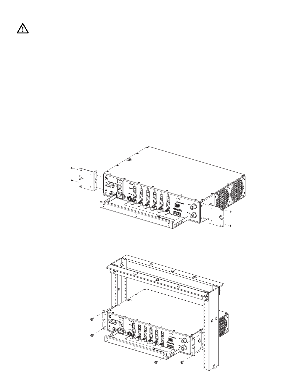
4.4.1 Rack Mount Installation
The DHU may be mounted in either a 19-inch or 23-inch EIA or WECO equipment rack. Both US
standard and metric machine screws are included for rack mounting the DHU. When loading the
DHU in a rack, make sure the mechanical loading of the rack is even to avoid a hazardous
condition such as a severely unbalanced rack. The rack should safely support the combined weight
of all the equipment it holds and be securely anchored. In addition, the maximum recommended
ambient temperature for the DHU is 50º C (122º F). Allow sufficient air circulation or space
between units when the DHU is installed in a multi-unit rack assembly because the operating
ambient temperature of the rack environment might be greater than room ambient.
ADCP-75-130 • Issue 3C • August 2006
Page 30
© 2006, ADC Telecommunications, Inc.
Warning: Wet conditions increase the potential for receiving an electrical shock when
installing or using electrically-powered equipment. To prevent electrical shock, never install
or use electrical equipment in a wet location or during a lightning storm.
Use the following procedure to install the DHU in the equipment rack:
1. The DHU is shipped with the mounting brackets installed for 19-inch rack installations.
If mounting the DHU in a 19-inch rack, proceed to step 4. If mounting the DHU in a 23-
inch rack, proceed to step 2.
2. Remove both mounting brackets from the DHU (requires TORX screwdriver with T20 bit)
3. Reinstall both mounting brackets so the long side of the bracket is flush with the DHU
front panel as shown in Figure 13. Use the screws removed in step 2 to re-attach the
brackets to the DHU enclosure.
4. Position the DHU in the designated mounting space in the rack (per system design) as
shown in Figure 14.
17271-A
REMOVE AND REINSTALL MOUNTING
BRACKETS AS SHOWN FOR
INSTALLATION IN 23-INCH RACKS
Figure 13. Installing the Mounting Brackets for 23-Inch Rack Installations
17281-A
Figure 14. DHU Rack Mount Installation
ADCP-75-130 • Issue 3C • August 2006
Page 31
© 2006, ADC Telecommunications, Inc.
5. Secure the mounting brackets to the rack using the four machine screws provided (use
#12-24 screws or M6 x 10 screws, whichever is appropriate).
Note: Provide a minimum of 3 inches (76 mm) of clearance space on both the left and right
sides of the DHU for air intake and exhaust.
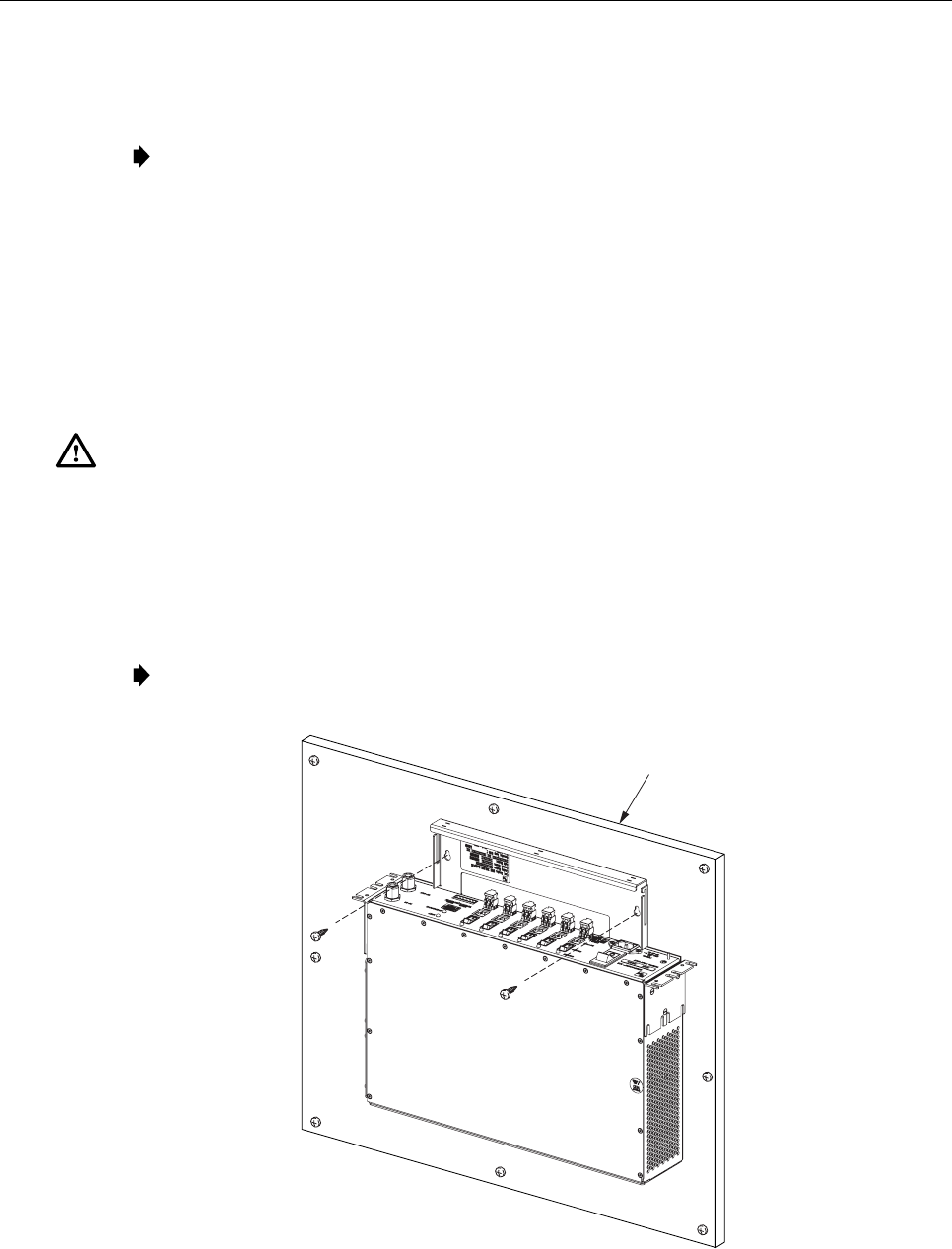
4.4.2 Wall-Mount Installation
The DHU may be mounted from any flat vertical surface. It is recommended that a backer
board such as 3/4-inch plywood be applied over the mounting surface to provide a secure base
for attaching the DHU. Two mounting holes are provided in the cable management tray for
securing the DHU to the mounting surface. The fasteners must be provided by the installer.
Use the following procedure to wall-mount the DHU:
Warning: Wet conditions increase the potential for receiving an electrical shock when
installing or using electrically-powered equipment. To prevent electrical shock, never install
or use electrical equipment in a wet location or during a lightning storm.
1. Obtain the appropriate fasteners (lag bolts, screw anchors, etc.) for securing the DHU to
the mounting surface.
2. Position the DHU on the mounting surface in the specified location (per the system
design) with the front panel facing up as shown in Figure 15.
Note: Provide a minimum of 3 inches (76 mm) of clearance space on both the left and right
sides of the DHU for air intake and exhaust.
17272-A
BACKER BOARD SUCH
AS 3/4-INCH PLYWOOD
Figure 15. DHU Wall-Mount Installation
ADCP-75-130 • Issue 3C • August 2006
Page 32
© 2006, ADC Telecommunications, Inc.
3. Using the DHU as a template, mark the location of the mounting holes on the mounting
surface.
Note: The mounting holes in the DHU cable management tray are spaced 11-21/32 inches
(296 mm) center to center.
4. Set the DHU aside and then drill appropriately sized holes in the mounting surface for
the fasteners.
5. Partially install the fasteners in the drilled holes. Leave the head of each fastener
protruding about 1/4 inch (6 mm) from the mounting surface.
6. Hang the DHU from the fasteners and then securely tighten each fastener.
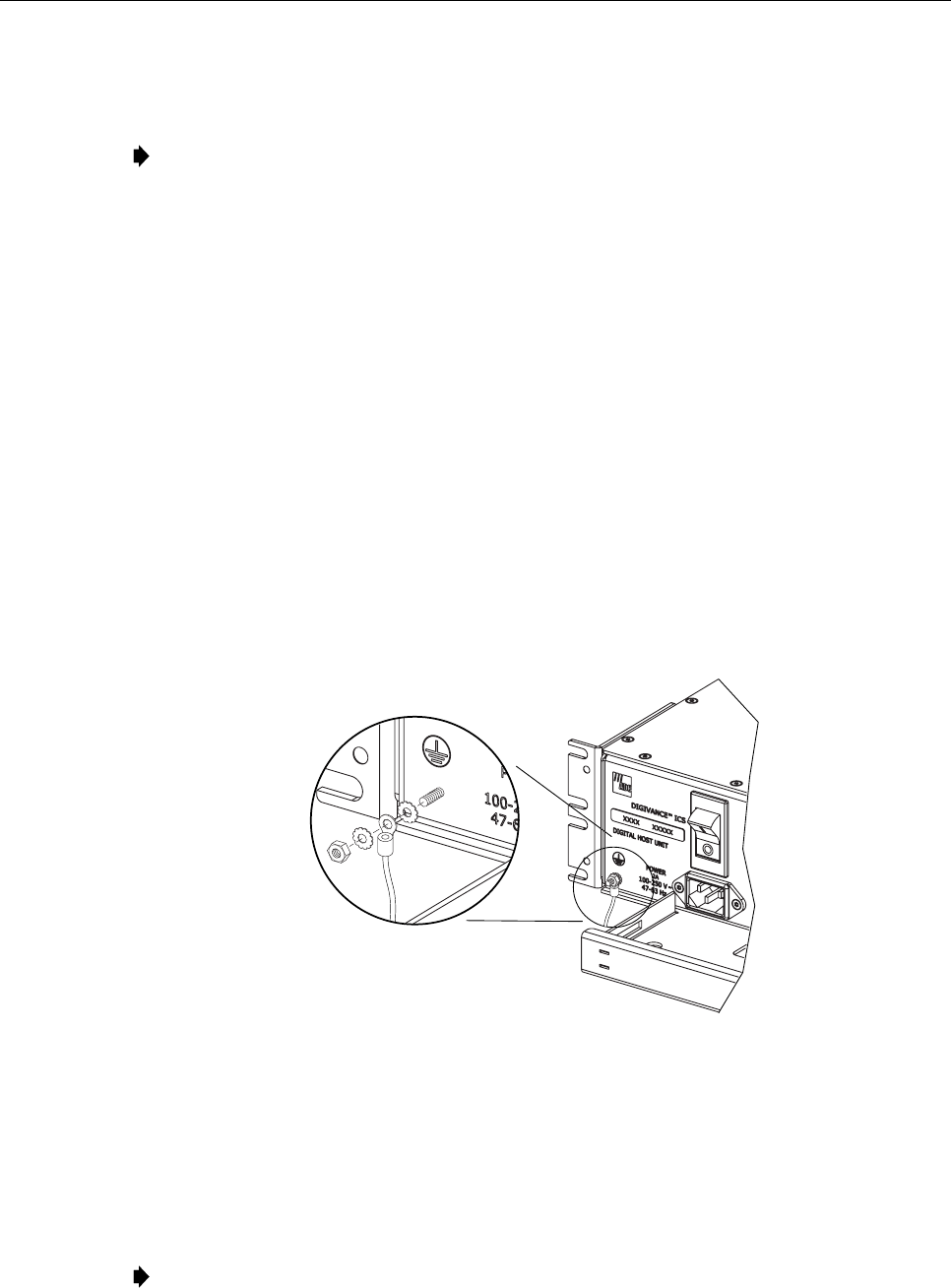
4.5 Chassis Ground Connections
A stud is provided on the front side of the chassis for connecting a grounding wire to the
chassis. Use the following procedure to connect the grounding wire to the chassis and to route
the grounding wire to an approved earth ground source:
1. Obtain a length of #18 AWG (1.00 mm) insulated stranded copper wire for use as a
chassis grounding wire.
2. Terminate one end of the wire with a ring terminal.
3. Locate the chassis ground stud at the front of the DHU as shown in Figure 16.
17279-A
Figure 16. Chassis Ground Stud
4. Secure the ring end of the wire to the chassis ground stud (see Figure 16) using the nut
and two star washers provided.
5. Route the free end of the chassis grounding wire to an approved (per local code or
practice) earth ground source.
6. Cut the chassis grounding wire to length and connect it to the approved ground source as
required by local code or practice.
Note: Be sure to maintain reliable grounding for rack and wall mounted equipment. Pay
particular attention to ground source connections.
ADCP-75-130 • Issue 3C • August 2006
Page 33
© 2006, ADC Telecommunications, Inc.
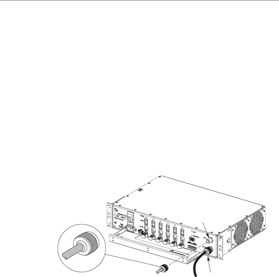
4.6 Coaxial Cable Connections
The RF interface between DHU and the BTS is supported through a pair of type N female
connectors mounted on the DHU front panel. One connector provides the coaxial cable
connection for the forward path (downlink) signal. The other connector provides the coaxial
cable connection for the reverse path (uplink) signal. Coaxial cables link the DHU to the BTS
through an interface device such as the HPCP or the RIU. Use the following procedure to
install the forward and reverse path coaxial cables and connect them to the DHU:
1. Obtain the required lengths of high performance, flexible, low loss 50-ohm coaxial
communications cable (RG 400 or equivalent) for all coaxial connections.
2. Route the forward path and reverse path coaxial cables (if not already routed) between
the DHU and the specified interface device (per system design) and cut to the required
length. Allow sufficient slack for dressing and organizing cables at the DHU.
3. Terminate each cable with a type N male connector following the connector supplier’s
recommendations.
4. Connect the forward path cable to the RF IN connector on the DHU front panel as
shown in Figure 17.
5. Connect the reverse path cable to the RF OUT connector on the DHU front panel.
17273-A
TYPE-N MALE CONNECTOR
RF IN CONNECTOR
(FORWARD PATH)
RF OUT CONNECTOR
(REVERSE PATH)
Figure 17. Forward and Reverse Path Coaxial Cable Connections
6. Dress and secure cables at the DHU per standard industry practice.
7. Adjust the RF signal levels and complete the remaining the forward and reverse path
coaxial cable connections as specified by the following:
Local Interface Using High Power Conditioning Panel: Refer to the High Power
Conditioning Panel User Manual (ADCP-75-175) for adjustment and connection procedure.
Remote Interface Using Remote Interface Unit: Refer to the Remote Interface Unit
User Manual (ADCP-75-178) for adjustment and connection procedure.
Local or Remote interface using ancillary interface device: Refer to Section 5.2,
Turn-Up System and Verify Operation, for adjustment and connection procedure.
ADCP-75-130 • Issue 3C • August 2006
Page 34
© 2006, ADC Telecommunications, Inc.
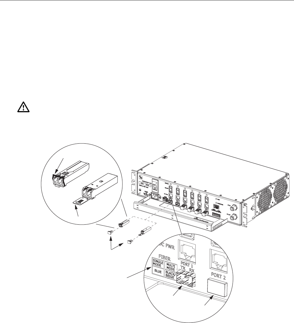
4.7 Modular Optical Transceiver Installation
The modular optical transceivers are available separately and may or may not be installed in
the DHU depending on the configuration ordered. If the optical transceivers are factory
installed in the DHU, skip this section and proceed to Section 4.8. If the optical transceivers
are not factory installed, use the following procedure to install each transceiver:
1. Slip on an Electro-Static Discharge (ESD) wrist strap and connect the ground wire to an
earth ground source such as the grounding stud on the DHU front panel. Wear the ESD
wrist strap while completing the optical transceiver installation procedure.
Warning: Electronic components can be damaged by static electrical discharge. To prevent
ESD damage, always wear an ESD wrist strap when handling electronic components.
2. Locate the appropriate transceiver socket on the front of the DHU as shown in Figure 18
and remove the port cover from the socket.
TXRX
DETAIL DRAWING OF
OPTICAL TRANSCEIVER
SOCKETS
DETAIL DRAWING
OF TYPE A AND TYPE B
MODULAR OPTICAL
TRANSCEIVERS
TXRX
TYPE A
TRANSCEIVER
TYPE B
TRANSCEIVER
RELEASE
LEVER
RELEASE TAB
OPTICAL
TRANSCEIVER
SOCKET
TRANSCEIVER COLOR CODE
BLUE = SINGLE-MODE (9 MICRON)
BLACK/
BEIGE = MULTI-MODE (50 OR 62.5 MICRON)
17258-A
PORT
COVER
DUST CAPS
Figure 18. Optical Transceiver Installation
3. Select the optical transceiver that corresponds to the type of fiber (single- or multi-mode)
required for the installation. The color of the transceiver (see transceiver color code in
Figure 18) corresponds to the fiber type.
4. Remove the transceiver from the anti-static packaging and orient for installation (see
Figure 18.).

ADCP-75-130 • Issue 3C • August 2006
Page 35
© 2006, ADC Telecommunications, Inc.
Note: Two types of optical transceivers, type A and type B, are available. Both types
provide the same functionality. On the type A optical transceiver, the release lever (see
Figure 18) must be closed for installation.
5. Insert the optical transceiver into the socket until it locks into place.
6. Replace the optical transceiver dust cap if it was removed for installation.
7. Repeat procedure for each optical transceiver that requires installation.
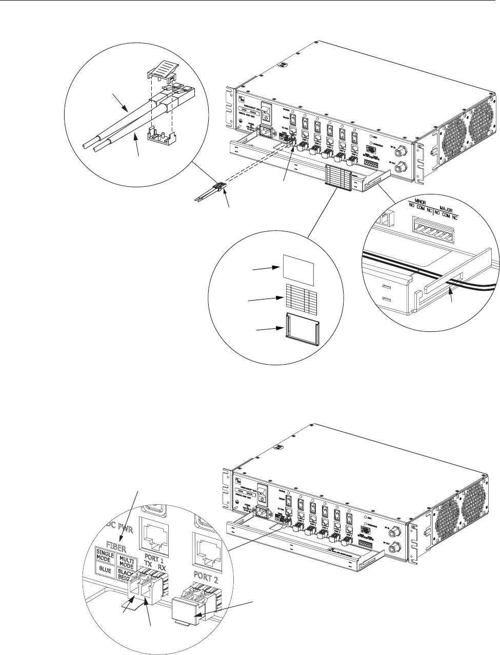
4.8 Ports 1–6 Optical Connections
The optical interface between the DHU and each DEU or DRU is supported by six optical
ports. Each of the six optical ports provides a duplex LC-type optical transceiver which is
mounted on the DHU front panel. One side of the transceiver provides the optical fiber
connection for the forward path (downlink) signal. The other side of the transceiver provides
the optical fiber connection for the reverse path (uplink) signal. Use the following procedure
to install the forward and reverse path optical fibers and to connect them to the DHU:
Danger: This equipment uses a Class 1 Laser according to FDA/CDRH rules. Laser
radiation can seriously damage the retina of the eye. Do not look into the ends of any optical
fiber. Do not look directly into the optical transceiver of any digital unit or exposure to laser
radiation may result. An optical power meter should be used to verify active fibers. A
protective cap or hood MUST be immediately placed over any radiating transceiver or optical
fiber connector to avoid the potential of dangerous amounts of radiation exposure. This
practice also prevents dirt particles from entering the transceiver or connector.
1. Obtain the required lengths of single- or multi-mode fiber optic cable.
2. Route the fiber optic cable between the DHU and the DEU or DRU (if not already
routed) and cut to required length. Allow sufficient slack for dressing and organizing the
cables at each unit. Maintain a minimum bend radius of 2 inches (50 mm).
Note: The maximum path lengths for the optical fibers are as follows: 500 meters (1,641
feet) for 62.5 micron core multi-mode fiber, 750 meters (2,461 feet) for 50 micron core
multi-mode fiber, and 10 km (32,808 ft) for 9 micron core single-mode fiber.
3. Terminate each optical fiber with a field-installable LC type fiber optic connector as
shown in Figure 19. Follow the instructions provided by the connector manufacturer for
installing the connector.
4. Test each fiber for optical loss as described in Subsection 6.4.2 of this manual.
5. Designate one of the fibers as the forward path fiber and the other as the reverse path
fiber and label both ends of each fiber with the path designation.
6. Use the plastic joiner provided with the LC connectors to join the DHU Port 1 forward
and reverse path connectors together (see Figure 19). Make sure the forward path and
reverse path connectors are oriented as shown.
Note: When viewing any Port 1-6 optical transceiver from the front, the forward path port is
on the left and the reverse path port is on the right as shown in Figure 20. In addition, single-
mode transceivers are colored blue and multi-mode transceivers are colored black or beige.
Both single- and multi-mode transceivers may be mounted on the same DHU.
ADCP-75-130 • Issue 3C • August 2006
Page 36
© 2006, ADC Telecommunications, Inc.
17274-A
REVERSE PATH (RX)
CONNECTOR
FORWARD PATH (TX)
CONNECTOR
OPTICAL CONNECTOR
ASSEMBLY DETAIL
PORT 1
OPTICAL
TRANSCEIVER
OPTICAL
CONNECTOR
CABLE
GUIDES
CABLE GUIDE
DETAIL
DESIGNATION CARD AND
HOLDER DETAIL
HOLDER
CARD
CLEAR
PLASTIC
COVER
Figure 19. Ports 1–6 Fiber Optic Cable Connections
17150-A
DETAIL DRAWING OF
OPTICAL PORT
REVERSE
PATH (RX)
FORWARD
PATH (TX)
DUST CAP (LEAVE IN PLACE
UNTIL READY TO INSTALL CONNECTOR)
TRANSCEIVER COLOR CODE
BLUE = SINGLE-MODE (9 MICRON)
BLACK/
BEIGE = MULTI-MODE (50 OR 62.5 MICRON)
Figure 20. Optical Transceiver Designations
ADCP-75-130 • Issue 3C • August 2006
Page 37
© 2006, ADC Telecommunications, Inc.
7. Remove the dust caps from the optical fiber connectors and the port 1 optical transceiver.
Note: Leave the dust cap in place on any unused optical transceiver.
8. Clean each connector (follow connector supplier’s recommendations) and then insert the
optical fiber connector pair into DHU optical port 1 (see Figure 19).
9. Place the optical fibers within the cable guides provided on the cable management tray (see
Figure 19) and then dress and secure the fibers at the DHU per standard industry practice.
10. Connect the forward and reverse path optical fibers to the DEU or the DRU as specified
in the instructions provided with that unit.
11. Use the designation card provided (see Figure 19) to indicate the location and name of
the DRU or DEU that is connected to each optical fiber pair. The designation card holder
may be attached to any convenient flat surface such as the DHU cable management tray
12. Repeat steps 1–11 for each remaining optical port.
4.9 DC Power Connections
The DC power interface between the DHU and each DRU is supported by six RJ-45 female
connectors. Each DHU RJ-45 connector provides nominal 48 VDC power for the associated
DRU except when the DRU is powered with an AC/DC converter. A category 3 or 5 twisted
pair cable is used to feed the power from the DHU to the DRU. Use the following procedure
to install the DC power cable and to connect it to the DHU.
1. Obtain the required length of category 3 or 5 twisted pair cable.
2. Route the cable between the DHU and the DRU (unless already routed) and then cut to
required length. Allow sufficient slack for dressing and organizing the cable at the DHU.
Note: The maximum distance for routing power cable is 500 meters (1,641 feet).
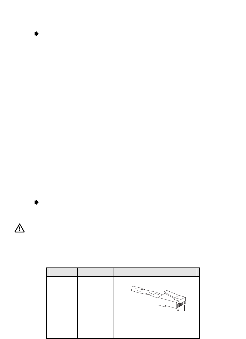
3. Terminate each end of the cable with a male RJ-45 connector. Match the wire color to
the connector pin as specified in Table 6.
Caution: The DRU will be damaged if the RJ-45 connector is wired incorrectly.
4. Perform a continuity test to verify that each wire is properly connected to the terminating
RJ-45 connector and check the connector for correct polarity (see diagram in Table 7).
Table 7. RJ-45 Connector Pin Designations
PIN NUMBER WIRE COLOR CONNECTOR PINS
1
2
3
4
5
6
7
8
White/Green
Green
White/Orange
Orange
White/Blue
Blue
White/Brown
Brown
PIN
1
PIN
8
+48 VDC ON PINS 1, 3, 5, AND 7
RETURN ON PINS 2, 4, 6, AND 8
16180-A
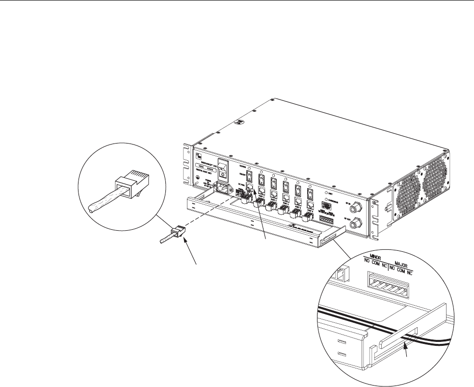
ADCP-75-130 • Issue 3C • August 2006
Page 38
© 2006, ADC Telecommunications, Inc.
5. Connect the DC power cable to the DHU port 1 DC PWR jack as shown in Figure 21.
6. Place the DC power cable within the cable guides provided (see Figure 21) and then
dress and secure the cable at the DHU per standard industry practice.
17275-A
RJ-45 CONNECTOR
DETAIL
PORT 1
DC POWER
CONNECTOR
RJ-45
CONNECTOR
CABLE
GUIDES
CABLE GUIDE
DETAIL
1
8
Figure 21. 48 VDC Power Cable Connection
7. Connect the DC power cable to the DRU as specified in the instructions provided with
that unit.
8. Repeat steps 1–7 for each remaining DRU that will be powered by the DHU.
4.10 External Alarm System Connections
The alarm interface between the DHU and an external alarm system is supported by a six-
terminal plug (with screw-type terminals) that connects to a receptacle mounted on the DHU
front panel. The terminal plug provides connections to normally open (NO) and normally
closed (NC) dry type alarm contacts for both minor and major alarms. A category 3 or 5 cable
is typically used to connect the DHU to the external alarm system. Use the following
procedure to install the alarm wiring and connect it to the DHU:
1. Obtain the required length of category 3 or 5 cable.
2. Route the cable between the DHU and the external alarm system (if not already routed)
and then cut to required length. Allow sufficient slack for dressing and organizing the
cable at the DHU.
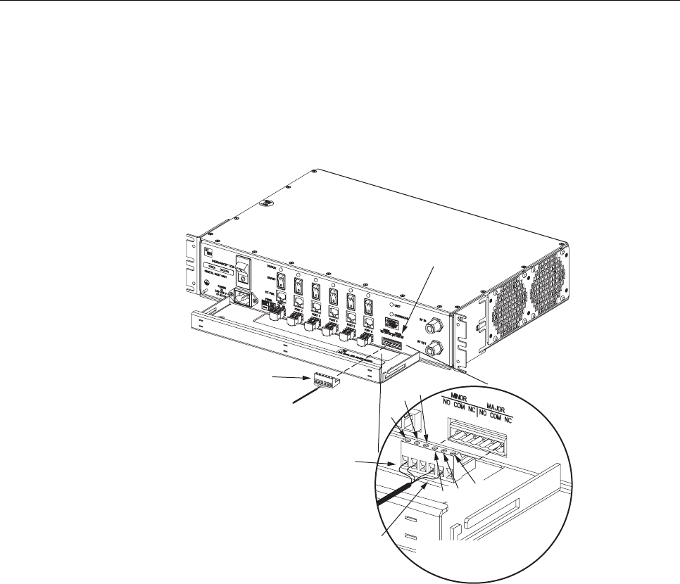
ADCP-75-130 • Issue 3C • August 2006
Page 39
© 2006, ADC Telecommunications, Inc.
3. Strip back the outer cable sheath and insulation to expose the wires at both ends of the
cable and strip back 0.2 inches (5 mm) of insulation each wire.
4. Connect the Major alarm wire pair to the MAJOR COM/NC or MAJOR COM/NO
terminals (whichever is required by the external alarm system) on the DHU alarm
terminal connector (supplied with DHU) as shown in Figure 22.
17278-A
ALARM
CONNECTOR
RECEPTACLE
MAJOR
ALARM
WIRES
MINOR
ALARM
WIRES
ALARM CONNECTOR
DETAIL
ALARM
CONNECTOR
NO
COM NC
MINOR
NO COM
NC
MAJOR
Figure 22. External Alarm System Connections
5. Connect the Minor alarm wire pair to the MINOR COM/NC or MINOR COM/NO
terminals (whichever is required by the external alarm system) on the DHU alarm
terminal connector as shown in Figure 22.
6. Insert the alarm terminal connector into the receptacle on the DHU front panel.
7. Connect the Major and Minor alarm wire pairs to the appropriate terminals on the
external alarm system.
8. Dress and secure cable per standard industry practice.
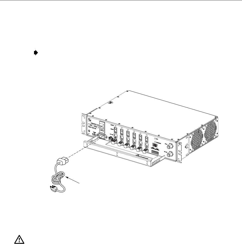
4.11 AC Power Connections
The AC power interface between the DHU and the AC power source is supported by a 3-wire
AC power cord connector located on the DHU front panel. The AC connector provides a
connection point for the power cord which is provided separately with the DHU. Use the
following procedure to install the AC power cord:
ADCP-75-130 • Issue 3C • August 2006
Page 40
© 2006, ADC Telecommunications, Inc.
1. Locate the 120 VAC power cord which is provided separately with the DHU. Use only
the AC power cord provided with the DHU or an equivalent UL/CUL listed 3-conductor,
18 AWG cord terminated in a molded-on plug cap rated 125 V, 15 A with a maximum
length of 6 feet (1.8 m).
Note: The DHU is intended to be used with a 3-wire grounding type plug which has a
grounding pin. Equipment grounding is required to ensure safe operation. Do not defeat
the grounding means. Verify DHU is reliably grounded when installed.
2. Place the DHU AC power ON/OFF switch, shown in Figure 23, in the OFF position
(press O).
17276-A
AC POWER CORD
Figure 23. AC Power Connection
3. Connect the receptacle end of the power cord to the AC connector on the DHU.
4. Route the plug end of the power cord to the specified AC outlet (per the system design)
and connect plug to outlet.
Warning: The current rating of the DHU is 2.0 Amps at 120 VAC. Avoid overloading circuits
which may cause damage to over-current protection devices and supply wiring.
5. Dress and secure cable per standard industry practice.
6. When all units of the Digivance ICS have been installed, refer to Section 4 of this
manual for the system power up and test procedures.
4.12 Create As-Built Drawing
Following installation, create an “as-built” drawing of the complete Digivance ICS system.
Using a drawing of the building floor plan, show the installed location of each piece of
equipment including the various Digivance electronic units, the antennas, the interface units,
and the microcell (if used). In addition, show the location and routing of all copper, coaxial,
and fiber optic cable runs used with the system. Retain the as-built drawing for reference
when troubleshooting or when planning for system expansion.