ADC Telecommunications DIS080AB Digivance® 800 MHz Indoor Coverage Solution User Manual 75130 CV
ADC Telecommunications Inc Digivance® 800 MHz Indoor Coverage Solution 75130 CV
Contents
- 1. Users manual 1
- 2. Users manual 2
- 3. Users manual 3
Users manual 3
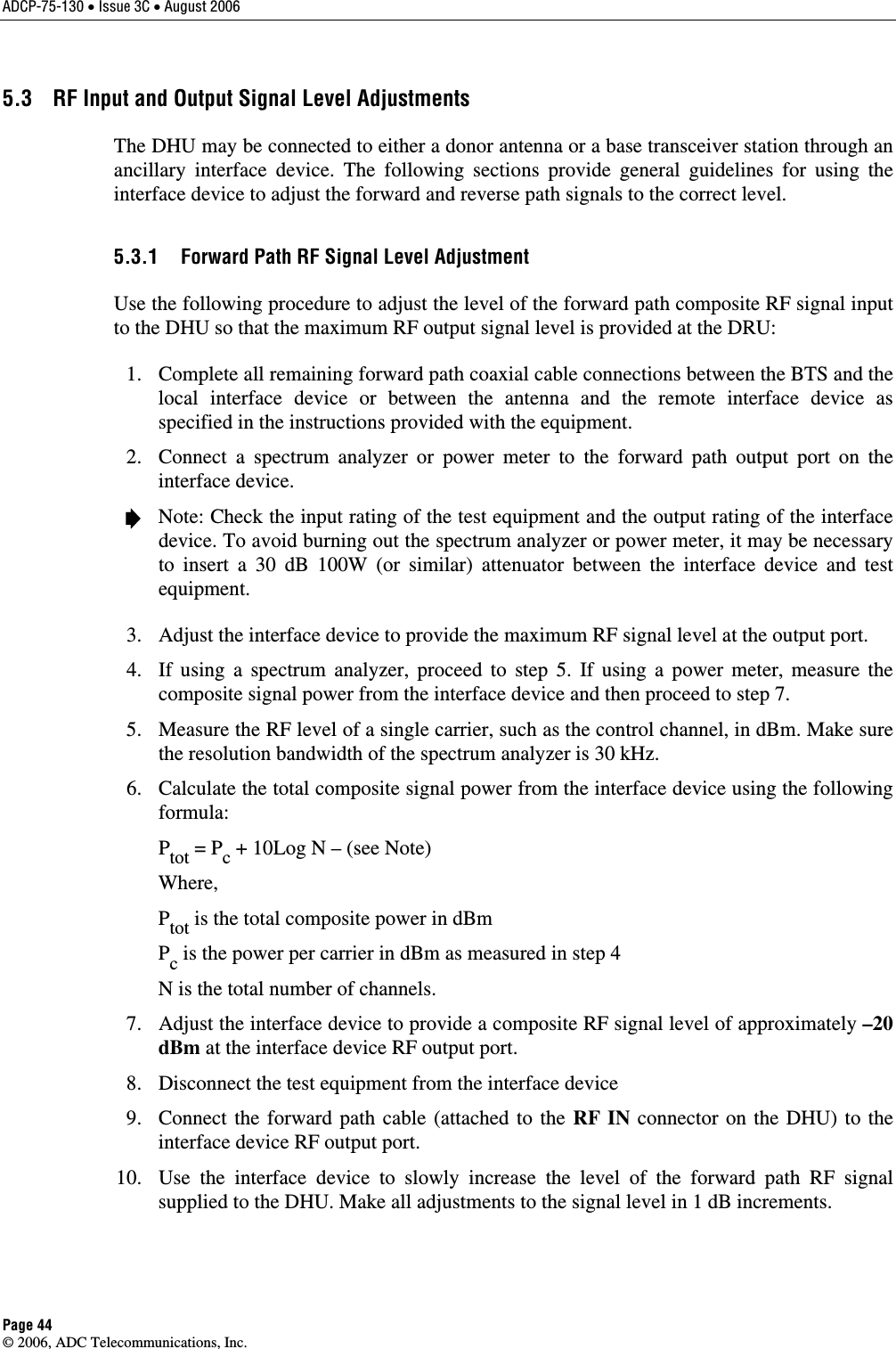
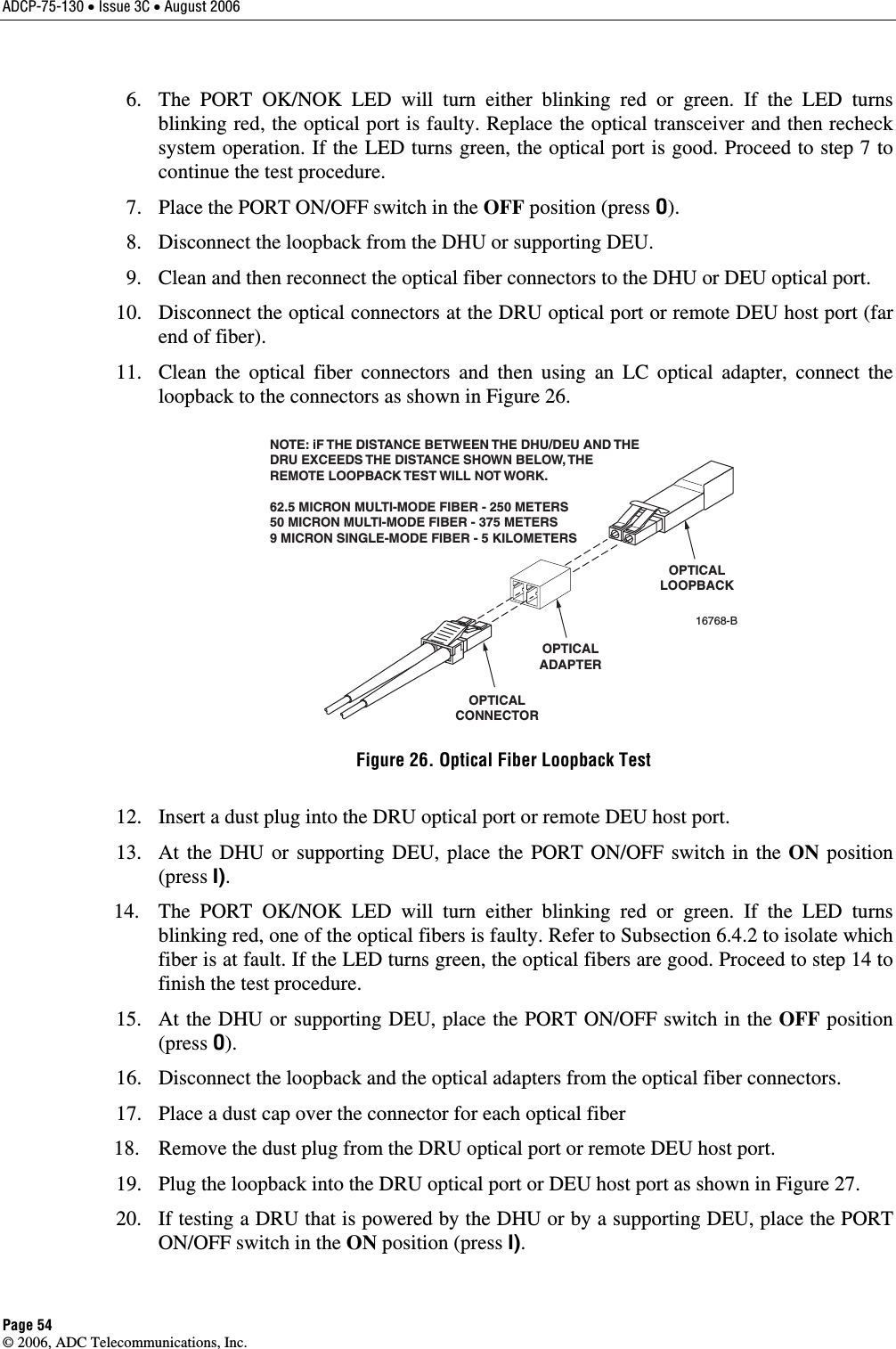
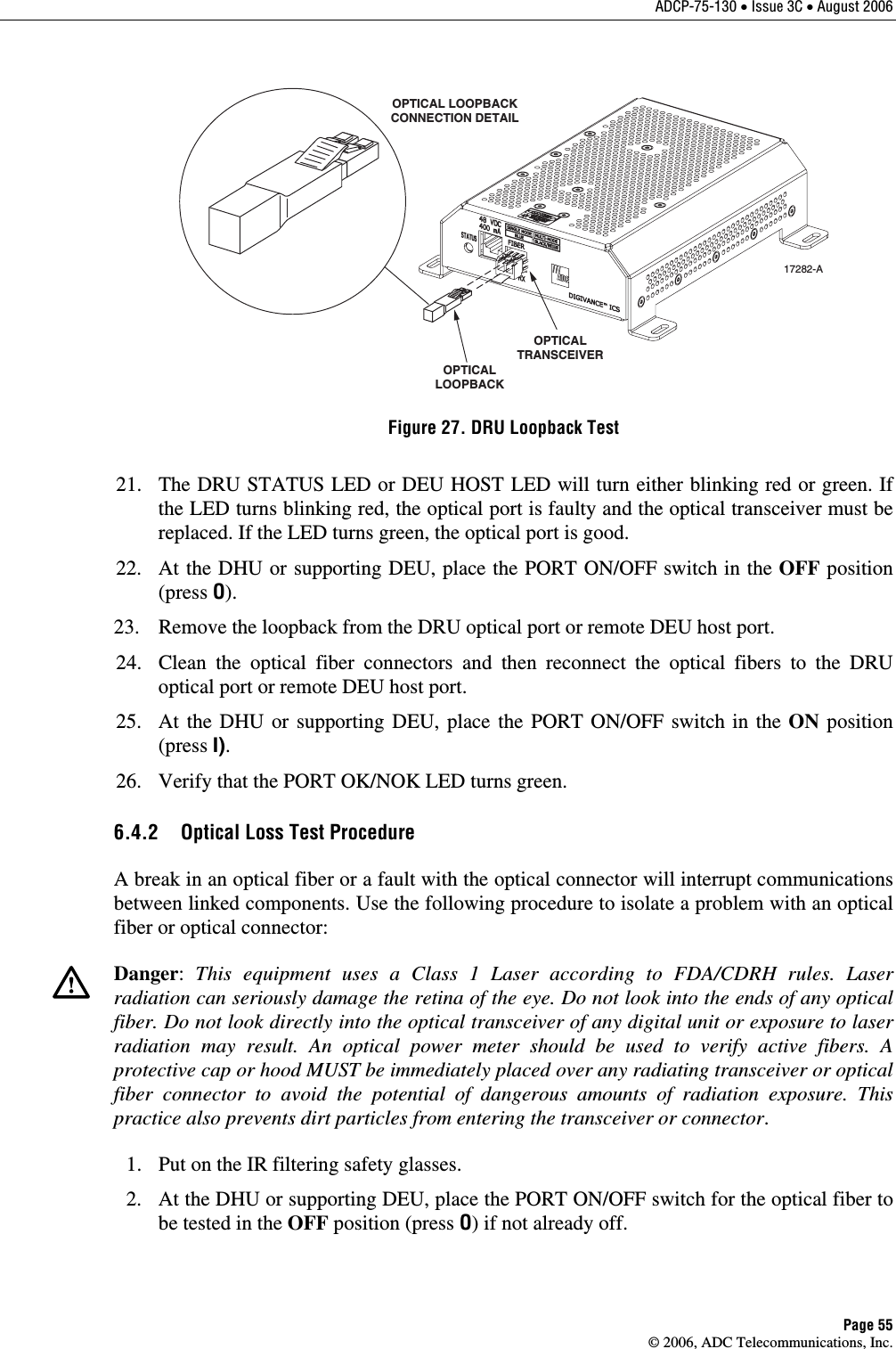
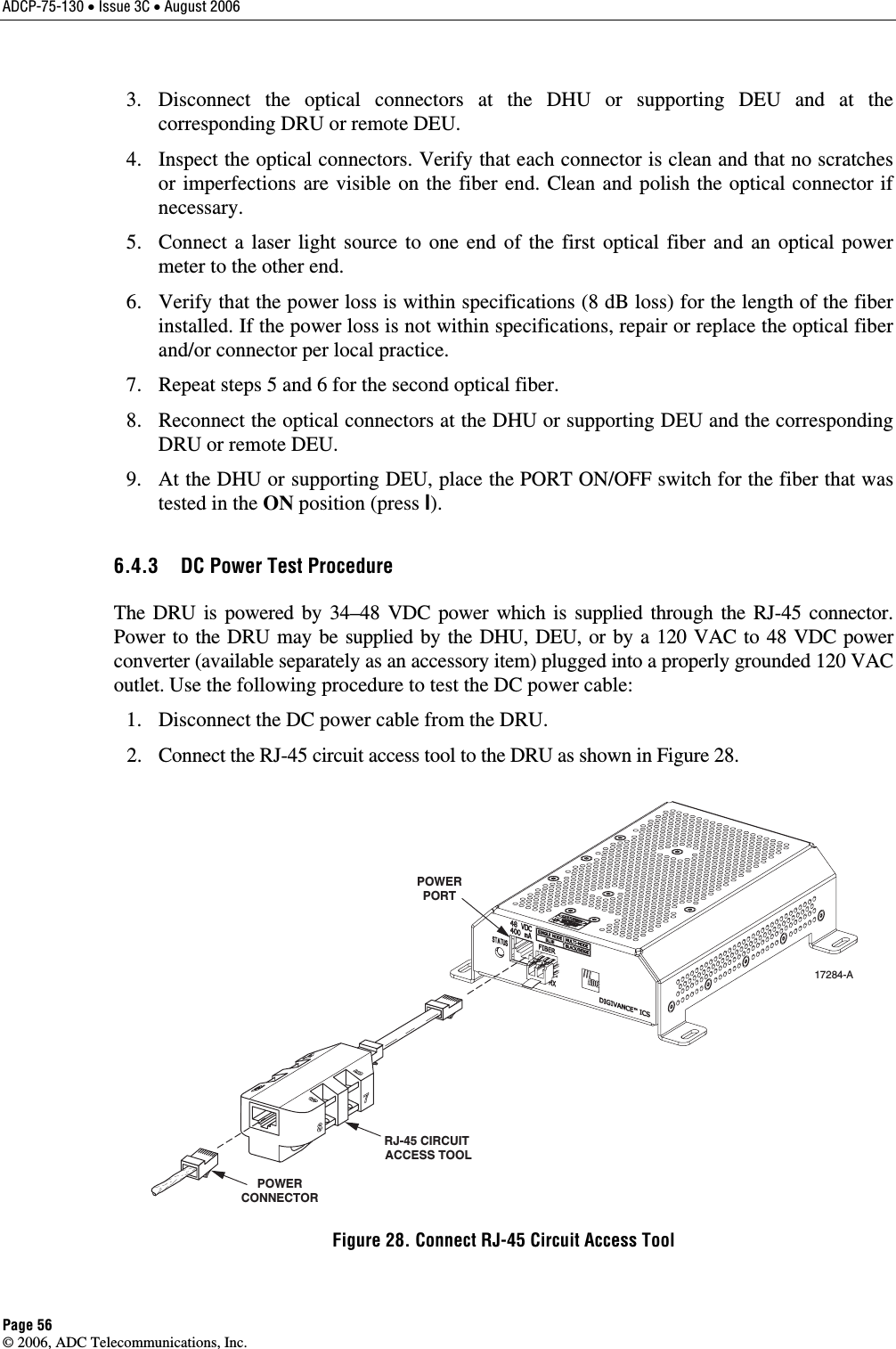
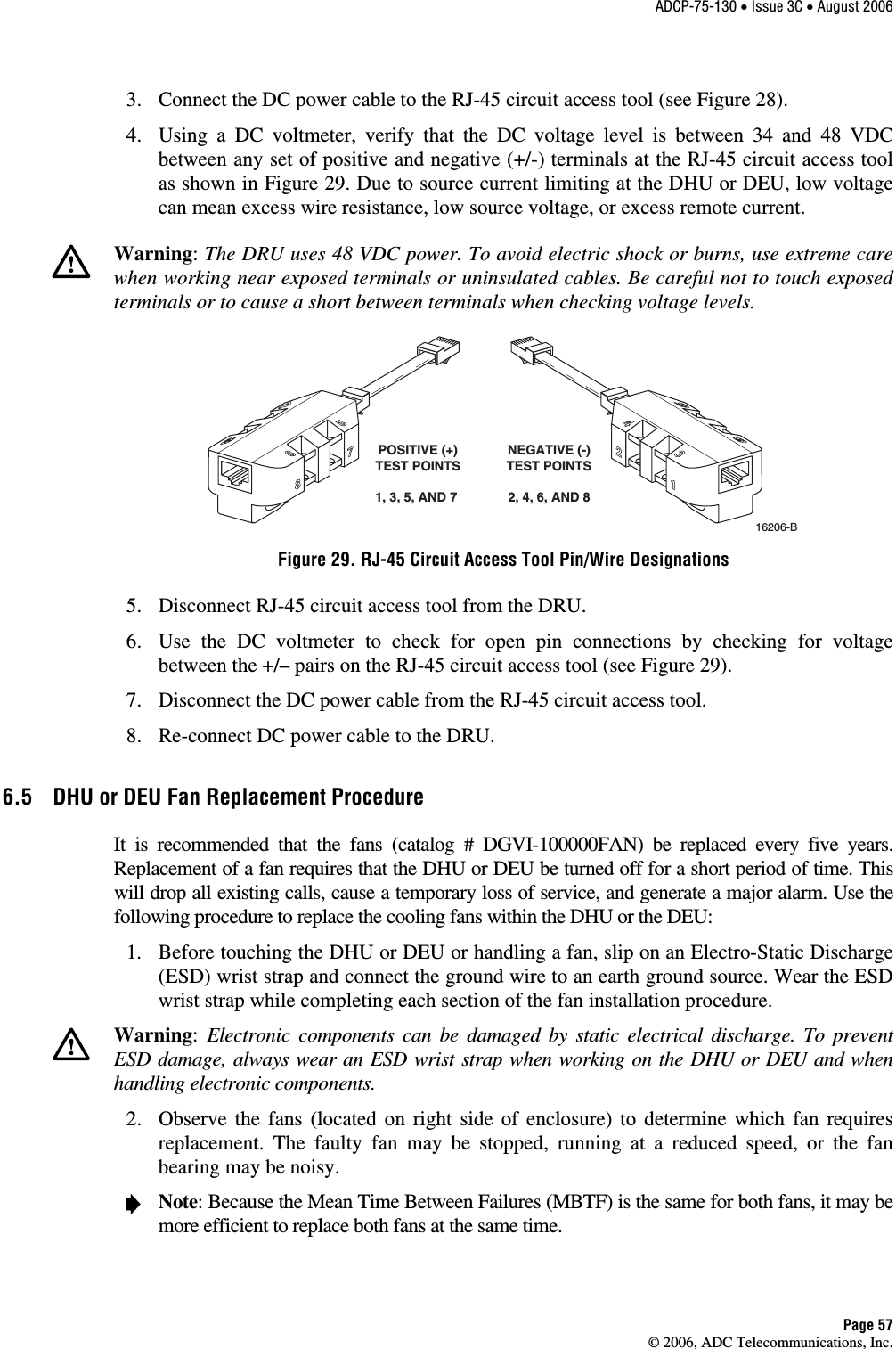
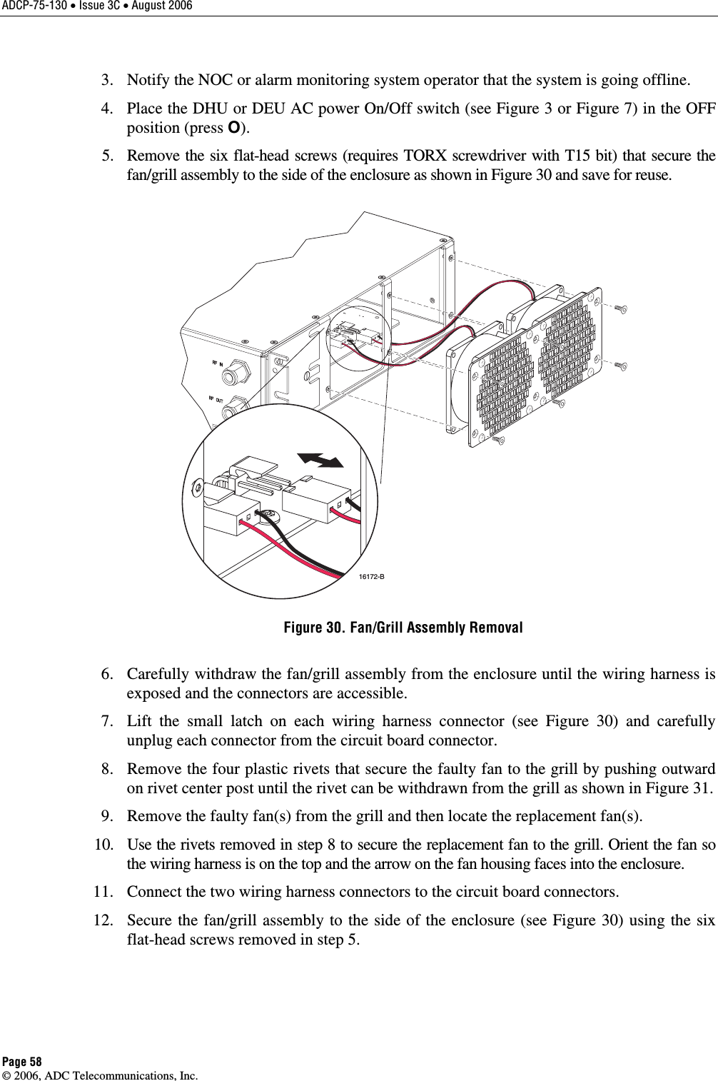
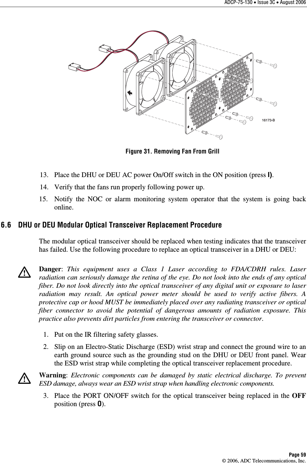
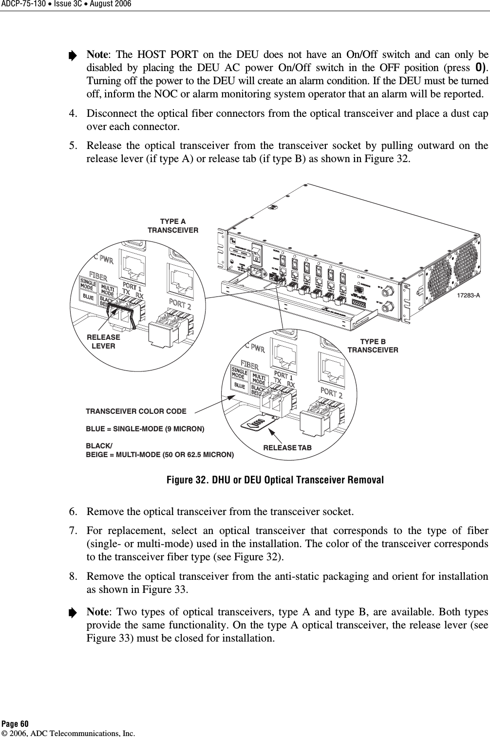
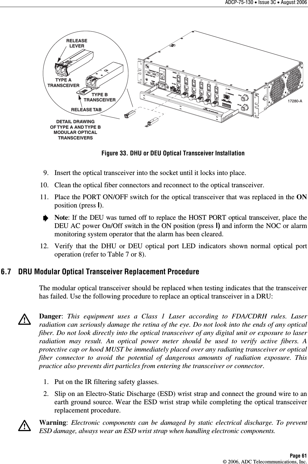
![ADCP-75-130 • Issue 3C • August 2006 Page 45 © 2006, ADC Telecommunications, Inc. Caution: Do not supply the DHU with an RF input signal that is 0 dBm or greater or the system could be damaged. 11. Continue to increase the forward path RF signal level until the DHU overdrive LED just begins to turn red. 12. Reduce the level of the RF input signal by 1 dB and then verify that the DHU Overdrive LED stays green. 5.3.2 Reverse Path RF Signal Level Adjustment The level of the reverse path composite RF signal output from the interface must be adjusted so that the correct RF signal level is input to the BTS or the antenna. When the level of the reverse path signal at the DRU antenna port is at a composite maximum of –40 dBm, the level of the RF output signal from the DHU will be –30 dBm. This equals a system gain of 10 dB. Use the following procedure to adjust the reverse path RF signal level: 1. Complete all remaining reverse path coaxial cable connections . 2. Determine the maximum acceptable DRU path loss per the system design specifications. 3. Determine the total cable loss that will be imposed by the reverse path coaxial cables and any other devices (splitters, connectors, etc) that will impose a lose on the signal. 4. Determine the total gain that will be provided by the DRU antenna and by the donor antenna (if present). 5. Use the following formula to calculate the total gain or loss that must be added by the interface device to provide unity gain: Reverse Path Gain/Loss Required = [∑ System Insertion Loss + Designed Path Loss*] – [System Gain (10 dB) + ∑ Antenna Gain] *Designed path loss is defined as the loss between a BTS antenna and a donor site antenna. 6. Adjust the interface device to provide the amount of gain or loss required per the calculation in step 5. 5.4 Test System Performance Testing the performance of the system involves completing various RF tests and telephone service tests that verify if the system is functioning properly. Use the following procedure to test the system performance: 1. Verify that the forward path (downlink) input signal level at the DHU is optimized. The peak COMPOSITE forward path input signal level at the DHU should be set at –20 dBm. Note: In a CDMA system, the power level is dependent on the traffic. For optimum operation in a CDMA system, the input signal level should be set below the level of the pilot signal. 2. Verify that the reverse path (uplink) signal level at the local BTS or donor antenna is optimized. Note that the reverse path output signal level required is dependent on service provider signal to noise requirements, ICS system noise floor, the service provider equipment, and the system configuration.](https://usermanual.wiki/ADC-Telecommunications/DIS080AB.Users-manual-3/User-Guide-746136-Page-5.png)