ADC Telecommunications DIS190AB Digivance 1900 MHz Indoor Coverage Solution User Manual 75132 CV
ADC Telecommunications Inc Digivance 1900 MHz Indoor Coverage Solution 75132 CV
Contents
- 1. Users Manual Section 1
- 2. Users Manual Section 2
- 3. Users Manual Section 3
Users Manual Section 3

ADCP-75-132 • Issue 2C • August 2006
Page 48
© 2006, ADC Telecommunications, Inc.
6 SYSTEM MAINTENANCE PROCEDURES
This section explains the alarm reporting system, provides a method for isolating and
troubleshooting faults, and provides procedures for replacing the modular transceivers and the
DHU or DEU cooling fans.
The Digivance ICS requires no regular maintenance to insure continuous and satisfactory
operation. Maintenance, as it applies to the Digivance ICS, primarily involves diagnosing and
correcting service problems as they occur. When an alarm is reported, it will be necessary to
follow a systematic troubleshooting procedure to locate the problem. Once the source of the
problem is isolated, the appropriate corrective action can be taken to restore service. The only
unit components that can be replaced are the cooling fans that mount in the DHU and DEU
and the modular optical transceivers. The failure of any other component within a unit will
require replacement of that unit.
6.1 Tools and Materials
The following tools and materials are required in order to complete the procedures in this
section:
• ESD wrist strap
• IR filtering safety glasses
• Optical loopback device (such as Stratos Lightwave LC5 series) and LC duplex adapter
• Optical power meter
• Magnification device for inspecting LC connectors
• Laser light source
• Multimeter
• Cell phone
• RJ-45 circuit access tool (such as the Harris 8-wire Banjo Adapter)
• Medium and small size flat-bladed screwdrivers
• TORX screwdriver (T10)
6.2 Fault Detection and Alarm Reporting
Detection of a fault by the Digivance ICS will generate an external alarm response. LED
indicators are provided on the front panel of the various units to indicate when a fault is
detected. In addition to LED indicators, the DHU also provides normally open (NO) and
normally closed (NC) dry alarm contacts for reporting minor and major alarms to an
external alarm system. A minor alarm is defined as a high temperature condition. A major
alarm is defined as any fault condition except high temperature.
When the DHU alarm contacts are connected to an external alarm system, detection of a fault
will generate an alarm at the Network Operations Center (NOC). However, various types of
faults may not generate an alarm response. In this case, the first indication of a problem will
probably be from cell phone users reporting a loss of service or poor service. Whenever a
problem is reported, whether by a external alarm system or by a call from a user, refer to
Subsection 6.3 to isolate and correct the fault.
ADCP-75-132 • Issue 2C • August 2006
Page 49
© 2006, ADC Telecommunications, Inc.
6.3 Fault Isolation and Troubleshooting
Fault isolation and troubleshooting guidelines are provided in Tables 11, 12, 13, and 14. When an
alarm is reported, determine the type of alarm generated (minor or major) and then check the LED
indicators on the DHU and note any that are red, yellow, or off. If any of the Port 1–6 OK/NOK LED
indicators on the DHU are red or yellow, also check the LED indicators on the connected DEU’s
and/or DRU’s and note if any are red or yellow. Start the troubleshooting process at the DHU and then
work toward the unit where the alarm originated. The troubleshooting tables are organized according
to unit type. Locate the problem in the appropriate table, check out the suggested possible causes, and
take corrective action as required.
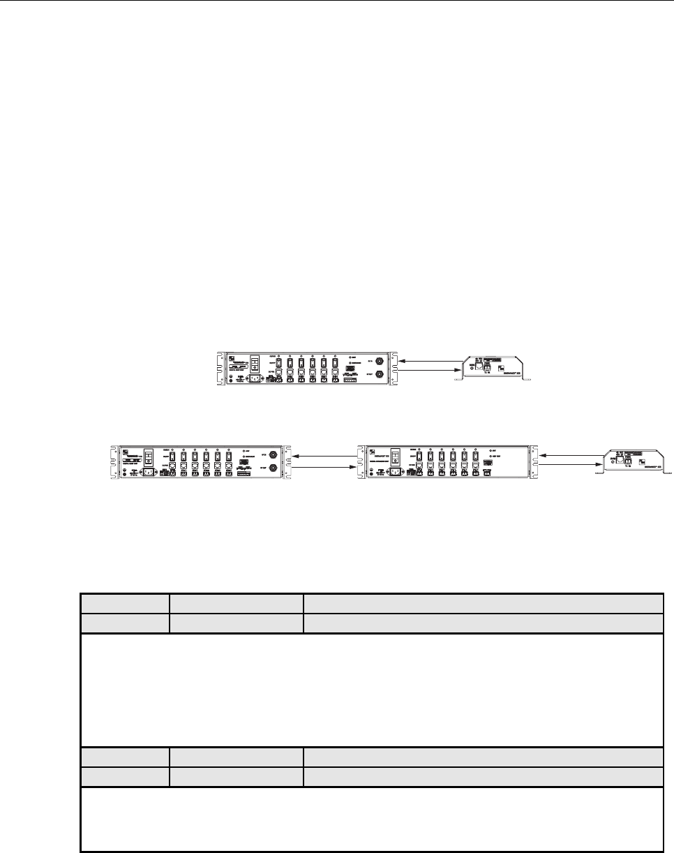
Figure 25 shows two basic ICS system configurations. The troubleshooting tables list possible causes
for various problems. If the cause of a particular problem is specific to either of the two system
configurations shown in Figure 25, the type of system configuration (1 or 2) will be referenced in the
table.
17962-A
FWD
REV
DRU
FWD
REV
DRU
FWD
REV
DIGITAL EXPANSION UNITDIGITAL HOST UNIT
DIGITAL HOST UNIT
(2)
(1)
Figure 25. ICS System Basic Configurations
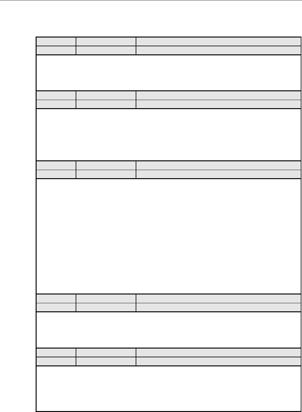
Table 11. DHU Fault Isolation and Troubleshooting Guidelines
Alarm Type LED LED COLOR
Minor UNIT Yellow
Problem : The DHU is overheating.
POSSIBLE CAUSE CORRECTIVE ACTION/COMMENTS
1. Air intake or exhaust openings to DHU
chassis blocked.
2. Ambient temperature > 50º C/122º F.
3. Faulty fan.
1. Remove cause of air-flow blockage.
2. Reduce ambient temperature.
3. Replace fan (see Subsection 6.5).
Alarm Type LED LED COLOR
Major UNIT Red
Problem : The DHU detects an internal circuitry fault.
POSSIBLE CAUSE CORRECTIVE ACTION/COMMENTS
1. Faulty DHU. 1. Replace DHU.
(Continued)
ADCP-75-132 • Issue 2C • August 2006
Page 50
© 2006, ADC Telecommunications, Inc.
Table 11. DHU Fault Isolation and Troubleshooting Guidelines (Continued)
Alarm Type LED LED COLOR
Major OVERDRIVE Red
Problem: Forward path RF input level too high.
POSSIBLE CAUSE CORRECTIVE ACTION/COMMENTS
1. Incorrect attenuation in forward path RF
coaxial link.
1. Adjust attenuation at RIU or HPCP.
Alarm Type LED LED COLOR
Minor OK/NOK Yellow
Problem: The DHU is receiving a minor alarm signal from the DEU.
POSSIBLE CAUSE CORRECTIVE ACTION/COMMENTS
1. The connected DEU is overheating (2). 1. Check DEU UNIT indicator and then refer to the
appropriate troubleshooting section for procedures.
Alarm Type LED LED COLOR
Major OK/NOK Blinking Red
Problem: The DHU is not receiving an optical signal from the DRU or DEU.
POSSIBLE CAUSE CORRECTIVE ACTION/COMMENTS
1. Forward and reverse path optical fibers
reversed between DHU and DRU (1); or
between DHU and DEU (2).
2. Faulty reverse path optical fiber between DHU
and DRU (1).
3. Faulty optical receive port at DHU or faulty
optical transmit port at DRU (1).
4. Faulty forward or reverse path optical fiber
between DHU and DEU (2).
1. Check fiber connections for correct polarity and
reverse connectors at either unit if mismatched.
2. Clean optical connector and then test optical fiber.
Repair or replace if faulty (see Subsection 6.4.2).
3. Make sure transceiver is fully plugged in and then
test optical port. Replace optical transceiver if
port is faulty (see Subsection 6.4.1).
4. Clean optical connectors and then test optical
fibers. Repair or replace if faulty (see
Subsection 6.4.2).
Alarm Type LED LED COLOR
Major OK/NOK Red
Problem: The DHU is receiving a major alarm signal from the DRU.
POSSIBLE CAUSE CORRECTIVE ACTION/COMMENTS
1. Faulty forward path optical fiber between
DHU and DRU (1).
2. Faulty optical transmit port at DHU or faulty
optical receive port at DRU (1).
3. The DRU is faulty (1 and 2).
4. Faulty forward or reverse path optical fiber
between the DEU and DRU (2).
1. Clean optical connector and then test optical fiber.
Repair or replace if faulty (see Subsection 6.4.2).
2. Make sure transceiver is fully plugged in and then
test optical port. Replace optical transceiver if
port is faulty (see Subsection 6.4.1).
3. Check DEU UNIT indicator or DRU STATUS
indicator and then refer to appropriate trouble-
shooting section for procedures.
4. Check the status of the OK/NOK LED on the
DEU and then Refer to Table 12.
ADCP-75-132 • Issue 2C • August 2006
Page 51
© 2006, ADC Telecommunications, Inc.
Table 12. DEU Fault Isolation and Troubleshooting Guidelines
Alarm Type LED LED COLOR
Minor UNIT Yellow
Problem : The DEU is overheating.
POSSIBLE CAUSE CORRECTIVE ACTION/COMMENTS
1. Air intake or exhaust openings to DEU
chassis blocked.
2. Ambient temperature > 50º C/122º F.
3. Faulty fan.
1. Remove cause of air-flow blockage.
2. Reduce ambient temperature.
3. Replace fan (see Subsection 6.5).
Alarm Type LED LED COLOR
Major UNIT Red
Problem : The DEU detects an internal circuitry fault.
POSSIBLE CAUSE CORRECTIVE ACTION/COMMENTS
1. Faulty DEU. 1. Replace DEU.
Alarm Type LED LED COLOR
Major HOST PORT Blinking Red
Problem: The DEU is not receiving an optical signal from the DHU.
POSSIBLE CAUSE CORRECTIVE ACTION/COMMENTS
1. Faulty forward path optical fiber between DEU
and DHU (2).
2. Faulty optical receive port at DEU or faulty
optical transmit port at DHU (2).
1. Clean optical connector and then test optical fiber.
Repair or replace if faulty (see Subsection 6.4.2).
2. Make sure transceiver is fully plugged it and then
test optical port. Replace optical transceiver if
port is faulty (see Subsection 6.4.1).
Alarm Type LED LED COLOR
Minor OK/NOK Yellow
Problem: The DEU is receiving a minor alarm signal from a connected DEU.
POSSIBLE CAUSE CORRECTIVE ACTION/COMMENTS
1. The connected DEU is overheating. 1. Check DEU UNIT indicator and then refer to the
appropriate troubleshooting section for procedures.
Alarm Type LED LED COLOR
Major OK/NOK Blinking Red
Problem: The DEU is not receiving an optical signal from the DRU.
POSSIBLE CAUSE CORRECTIVE ACTION/COMMENTS
1. Forward and reverse path optical fibers
reversed between DEU and DRU.
2. Faulty reverse path optical fiber between DEU
and DRU.
3. Faulty optical receive port at DEU or faulty
optical transmit port at DRU.
1. Check fiber connections for correct polarity and
reverse connectors at either unit if mismatched.
2. Clean optical connector and then test optical fiber.
Repair or replace if faulty (see Subsection 6.4.2).
3. Make sure transceiver is fully plugged in and then
test optical port. Replace optical transceiver if
port is faulty (see Subsection 6.4.1).
(Continued)
ADCP-75-132 • Issue 2C • August 2006
Page 52
© 2006, ADC Telecommunications, Inc.
Table 12. DEU Fault Isolation and Troubleshooting Guidelines (Continued)
Alarm Type LED LED COLOR
Major OK/NOK Red
Problem: The DEU is receiving a major alarm signal from the connected DRU.
POSSIBLE CAUSE CORRECTIVE ACTION/COMMENTS
1. Faulty forward path optical fiber between DEU
and DRU.
2. Faulty optical transmit port at DEU or faulty
optical receive port at DRU.
3. The connected DRU is faulty.
1. Clean optical connector and then test optical fiber.
Repair or replace if faulty (see Subsection 6.4.2).
2. Make sure transceiver is fully plugged in and then
test optical port. Replace optical transceiver if
port is faulty (see Subsection 6.4.1).
3. Check DRU STATUS indicator and then refer
to appropriate troubleshooting section for
procedures.
Table 13. DRU Fault Isolation and Troubleshooting Guidelines
Alarm Type LED LED COLOR
Major STATUS Off
Problem : The DRU is not powered.
POSSIBLE CAUSE CORRECTIVE ACTION/COMMENTS
1. DC power cable open.
2. No power or insufficient power output from
AC/DC power converter, DHU (1), or DEU (2).
3. Faulty DRU.
1. Test cable for continuity and repair or replace if
faulty.
2. Check DC voltage level at the DRU (see Subsection
6.4.3). Replace converter, DHU, or DEU (whichever
applies) if voltage is not within 34 to 48 VDC.
3. Replace DRU.
Alarm Type LED LED COLOR
Major STATUS Blinking Red
Problem : The DRU is not receiving an optical signal from the DHU or DEU; or the DHU or DEU is not receiving
an optical signal from the DRU.
POSSIBLE CAUSE CORRECTIVE ACTION/COMMENTS
1. Faulty forward or reverse path optical fiber
between DHU and DRU (1), DEU and
DRU (2), or DEU and DHU (2).
2. Faulty optical transmit or receive port at the
DHU (1) or DEU (2); or faulty optical
transmit or receive port at DRU (1 and 2).
1. Clean optical connector and then test optical fiber.
Repair or replace if faulty (see Subsection 6.4.2).
2. Make sure transceiver is fully plugged it and then
test optical port. Replace optical transceiver if
port is faulty (see Subsection 6.4.1).
Alarm Type LED LED COLOR
Major STATUS Red
Problem: The DRU detects an internal circuitry fault.
POSSIBLE CAUSE CORRECTIVE ACTION/COMMENTS
1. Faulty DRU. 1. Replace DRU.
ADCP-75-132 • Issue 2C • August 2006
Page 53
© 2006, ADC Telecommunications, Inc.
Table 14. System Fault Isolation and Troubleshooting Guidelines
Alarm Type LED LED COLOR
None All Normal
Problem: One or more of the DRU’s does not function following initial turn-up
POSSIBLE CAUSE CORRECTIVE ACTION/COMMENTS
1. The DHU and DRU(s) frequency switches
are set to different bands.
1. Reset DHU and DRU(s) frequency switches to the
same band.
Alarm Type LED LED COLOR
None All Normal
Problem: Loss of phone service from one DRU. Service normal at all other DRU’s.
POSSIBLE CAUSE CORRECTIVE ACTION/COMMENTS
1. DRU antenna cable disconnected.
2. DRU antenna obstructed or misdirected.
3. DRU antenna faulty.
4. DRU faulty.
1. Re-connect DRU antenna cable to DRU.
2. Remove antenna obstruction or re-orient antenna.
3. Replace antenna.
4. Replace DRU.
Alarm Type LED LED COLOR
None All Normal
Problem: Loss of phone service from all DRU’s.
POSSIBLE CAUSE CORRECTIVE ACTION/COMMENTS
1. Local Interface: Faulty forward path coaxial
connections between the DHU, HPCP and
BTS. Faulty reverse path coaxial connec-
tions between the DHU and BTS.
2. Remote Interface: Faulty forward or reverse
path coaxial connections between the DHU
and the RIU. Faulty coaxial connections
between the RIU and donor antenna.
3. Faulty HPCP or RIU.
4. Faulty DHU
5. Fault with cellular network or equipment.
1. Check forward path signals at the HPCP and the
DHU. Check reverse path signals at the BTS.
2. Check forward and reverse path signals at the DHU,
RIU, and donor antenna.
3. Adjust or replace HPCP or RIU.
4. Replace DHU.
5. Contact cell service provider and verify that
cellular network and equipment is operational.
Alarm Type LED LED COLOR
None All Normal
Problem: Calls may be originated and terminated but service is noisy.
POSSIBLE CAUSE CORRECTIVE ACTION/COMMENTS
1. Some electrical device in the immediate
vicinity is creating interference.
1. Try turning off each device that may be causing
interference and see if problem corrects itself.
Alarm Type LED LED COLOR
None All Normal
Problem: Sudden high rate of blocked calls (delay dial tone).
POSSIBLE CAUSE CORRECTIVE ACTION/COMMENTS
1. Too many users for the number of channels
available.
2. Faulty DHU, DEU, or DRU.
1. Wait a few minutes and try dialing again. Upgrade
service if additional channels are required.
2. Replace defective unit.
ADCP-75-132 • Issue 2C • August 2006
Page 54
© 2006, ADC Telecommunications, Inc.
6.4 Test Procedures
6.4.1 Optical Loopback Test Procedure
Dirty optical connectors, a faulty optical transceiver, a break in an optical fiber, or a fault in
an optical connector will interrupt communications between fiber-linked components. Use the
following procedure to determine if a fault exists with an optical port or with an optical fiber:
Danger: This equipment uses a Class 1 Laser according to FDA/CDRH rules. Laser
radiation can seriously damage the retina of the eye. Do not look into the ends of any optical
fiber. Do not look directly into the optical transceiver of any digital unit or exposure to laser
radiation may result. An optical power meter should be used to verify active fibers. A
protective cap or hood MUST be immediately placed over any radiating transceiver or optical
fiber connector to avoid the potential of dangerous amounts of radiation exposure. This
practice also prevents dirt particles from entering the transceiver or connector.
1. Put on the IR filtering safety glasses.
2. At the DHU or supporting DEU, place the PORT ON/OFF switch for the fiber port or
fiber to be tested in the OFF position (press O).
3. Disconnect the optical connectors for the fiber port to be tested and place a dust cap over
each connector.
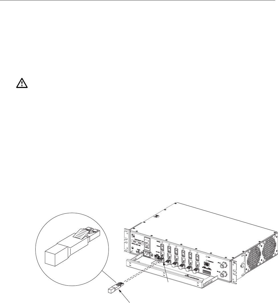
4. Plug a loopback into the optical port to be tested as shown in Figure 26.
17277-A
OPTICAL LOOPBACK
CONNECTION DETAIL
PORT 1
OPTICAL
TRANSCEIVER
OPTICAL
LOOPBACK
Figure 26. DHU/DEU Loopback Test
5. At the DHU or supporting DEU, place the PORT ON/OFF switch in the ON position
(press I).
ADCP-75-132 • Issue 2C • August 2006
Page 55
© 2006, ADC Telecommunications, Inc.
6. The PORT OK/NOK LED will turn either blinking red or green. If the LED turns
blinking red, the optical port is faulty. Replace the optical transceiver and then recheck
system operation. If the LED turns green, the optical port is good. Proceed to step 7 to
continue the test procedure.
7. Place the PORT ON/OFF switch in the OFF position (press O).
8. Disconnect the loopback from the DHU or supporting DEU.
9. Clean and then reconnect the optical fiber connectors to the DHU or DEU optical port.
10. Disconnect the optical connectors at the DRU optical port or remote DEU host port (far
end of fiber).
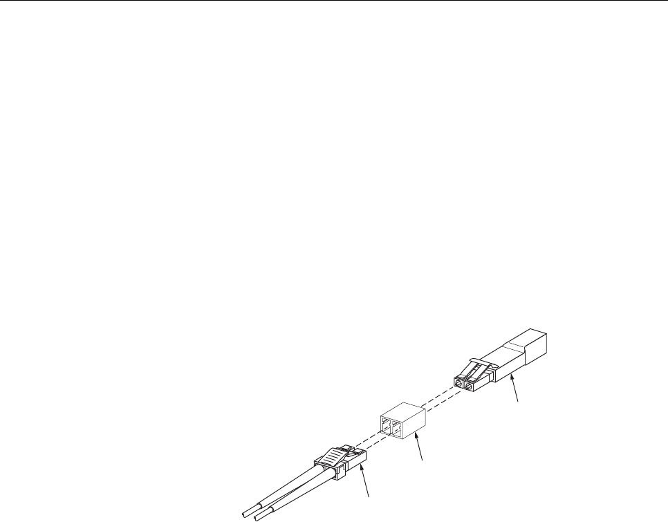
11. Clean the optical fiber connectors and then using an LC optical adapter, connect the
loopback to the connectors as shown in Figure 27.
16768-B
OPTICAL
ADAPTER
OPTICAL
LOOPBACK
OPTICAL
CONNECTOR
NOTE: iF THE DISTANCE BETWEEN THE DHU/DEU AND THE
DRU EXCEEDS THE DISTANCE SHOWN BELOW, THE
REMOTE LOOPBACK TEST WILL NOT WORK.
62.5 MICRON MULTI-MODE FIBER - 250 METERS
50 MICRON MULTI-MODE FIBER - 375 METERS
9 MICRON SINGLE-MODE FIBER - 5 KILOMETERS
Figure 27. Optical Fiber Loopback Test
12. Insert a dust plug into the DRU optical port or remote DEU host port.
13. At the DHU or supporting DEU, place the PORT ON/OFF switch in the ON position
(press I).
14. The PORT OK/NOK LED will turn either blinking red or green. If the LED turns
blinking red, one of the optical fibers is faulty. Refer to Subsection 6.4.2 to isolate which
fiber is at fault. If the LED turns green, the optical fibers are good. Proceed to step 14 to
finish the test procedure.
15. At the DHU or supporting DEU, place the PORT ON/OFF switch in the OFF position
(press O).
16. Disconnect the loopback and the optical adapters from the optical fiber connectors.
17. Place a dust cap over the connector for each optical fiber
18. Remove the dust plug from the DRU optical port or remote DEU host port.
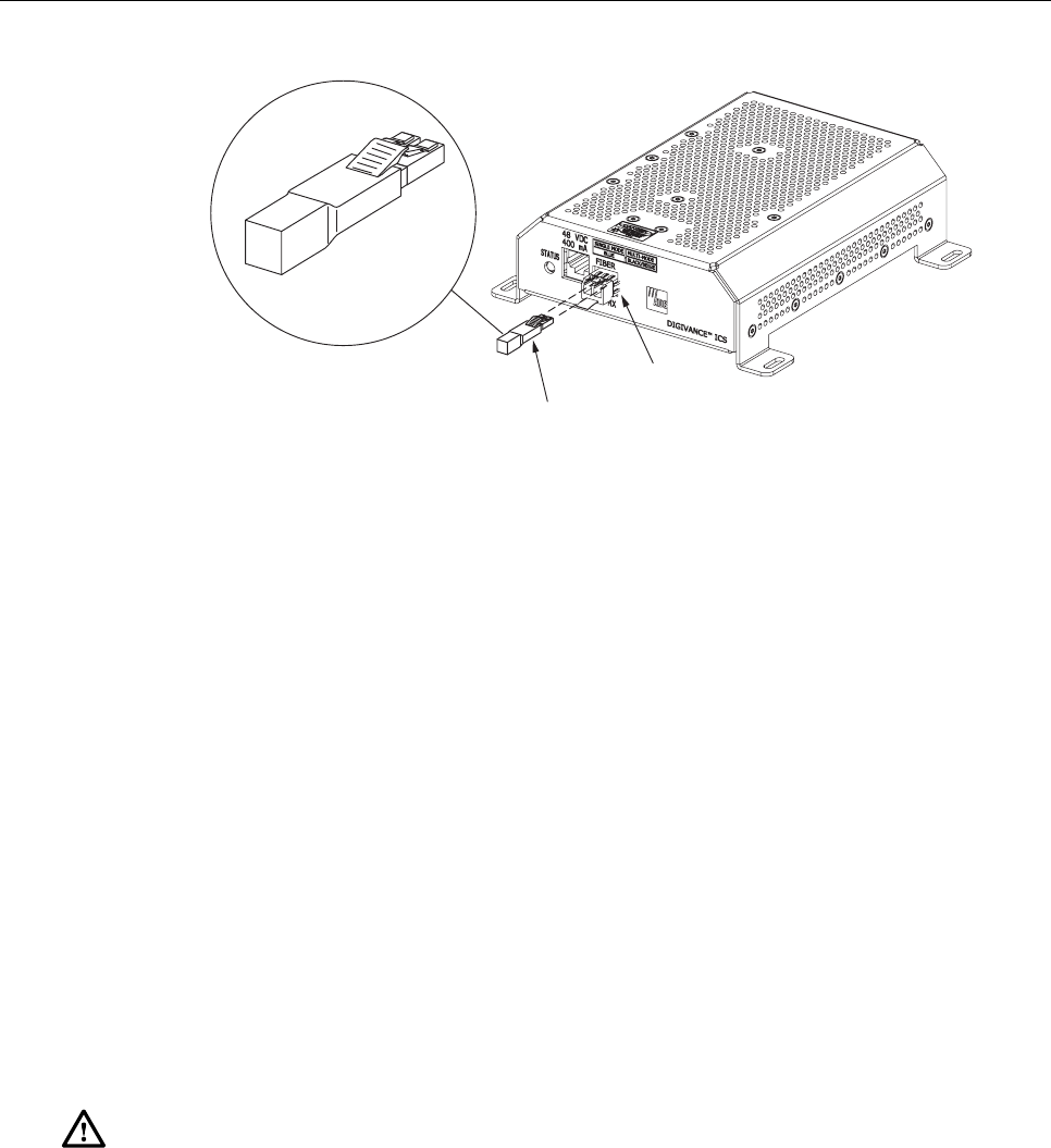
19. Plug the loopback into the DRU optical port or DEU host port as shown in Figure 28.
20. If testing a DRU that is powered by the DHU or by a supporting DEU, place the PORT
ON/OFF switch in the ON position (press I).
ADCP-75-132 • Issue 2C • August 2006
Page 56
© 2006, ADC Telecommunications, Inc.
17282-A
OPTICAL LOOPBACK
CONNECTION DETAIL
OPTICAL
TRANSCEIVER
OPTICAL
LOOPBACK
Figure 28. DRU Loopback Test
21. The DRU STATUS LED or DEU HOST LED will turn either blinking red or green. If
the LED turns blinking red, the optical port is faulty and the optical transceiver must be
replaced. If the LED turns green, the optical port is good.
22. At the DHU or supporting DEU, place the PORT ON/OFF switch in the OFF position
(press O).
23. Remove the loopback from the DRU optical port or remote DEU host port.
24. Clean the optical fiber connectors and then reconnect the optical fibers to the DRU
optical port or remote DEU host port.
25. At the DHU or supporting DEU, place the PORT ON/OFF switch in the ON position
(press I).
26. Verify that the PORT OK/NOK LED turns green.
6.4.2 Optical Loss Test Procedure
A break in an optical fiber or a fault with the optical connector will interrupt communications
between linked components. Use the following procedure to isolate a problem with an optical
fiber or optical connector:
Danger: This equipment uses a Class 1 Laser according to FDA/CDRH rules. Laser
radiation can seriously damage the retina of the eye. Do not look into the ends of any optical
fiber. Do not look directly into the optical transceiver of any digital unit or exposure to laser
radiation may result. An optical power meter should be used to verify active fibers. A
protective cap or hood MUST be immediately placed over any radiating transceiver or optical
fiber connector to avoid the potential of dangerous amounts of radiation exposure. This
practice also prevents dirt particles from entering the transceiver or connector.
1. Put on the IR filtering safety glasses.
2. At the DHU or supporting DEU, place the PORT ON/OFF switch for the optical fiber to
be tested in the OFF position (press O) if not already off.
ADCP-75-132 • Issue 2C • August 2006
Page 57
© 2006, ADC Telecommunications, Inc.
3. Disconnect the optical connectors at the DHU or supporting DEU and at the
corresponding DRU or remote DEU.
4. Inspect the optical connectors. Verify that each connector is clean and that no scratches
or imperfections are visible on the fiber end. Clean and polish the optical connector if
necessary.
5. Connect a laser light source to one end of the first optical fiber and an optical power
meter to the other end.
6. Verify that the power loss is within specifications (8 dB loss) for the length of the fiber
installed. If the power loss is not within specifications, repair or replace the optical fiber
and/or connector per local practice.
7. Repeat steps 5 and 6 for the second optical fiber.
8. Reconnect the optical connectors at the DHU or supporting DEU and the corresponding
DRU or remote DEU.
9. At the DHU or supporting DEU, place the PORT ON/OFF switch for the fiber that was
tested in the ON position (press I).
6.4.3 DC Power Test Procedure
The DRU is powered by 34–48 VDC power which is supplied through the RJ-45 connector.
Power to the DRU may be supplied by the DHU, DEU, or by a 120 VAC to 48 VDC power
converter (available separately as an accessory item) plugged into a properly grounded 120 VAC
outlet. Use the following procedure to test the DC power cable:
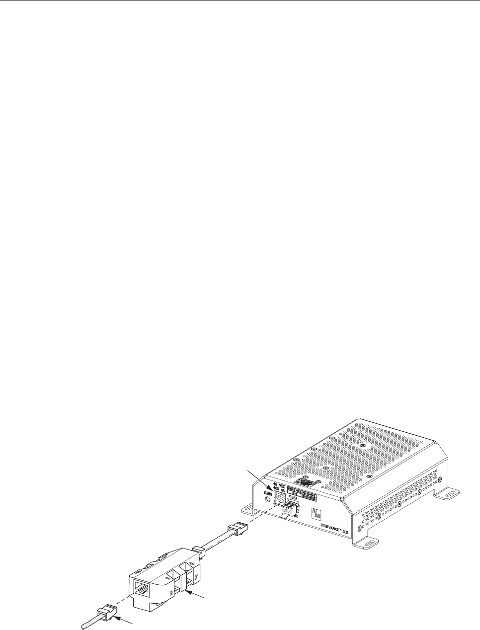
1. Disconnect the DC power cable from the DRU.
2. Connect the RJ-45 circuit access tool to the DRU as shown in Figure 29.
POWER
PORT
POWER
CONNECTOR
RJ-45 CIRCUIT
ACCESS TOOL
17284-A
Figure 29. Connect RJ-45 Circuit Access Tool
ADCP-75-132 • Issue 2C • August 2006
Page 58
© 2006, ADC Telecommunications, Inc.
3. Connect the DC power cable to the RJ-45 circuit access tool (see Figure 29).
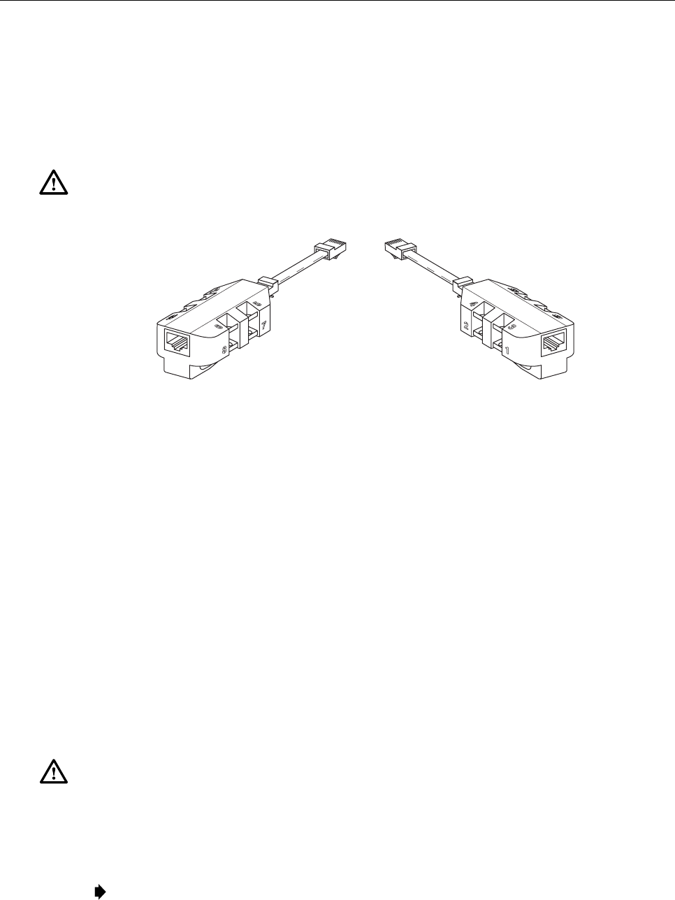
4. Using a DC voltmeter, verify that the DC voltage level is between 34 and 48 VDC
between any set of positive and negative (+/-) terminals at the RJ-45 circuit access tool
as shown in Figure 30. Due to source current limiting at the DHU or DEU, low voltage
can mean excess wire resistance, low source voltage, or excess remote current.
Warning: The DRU uses 48 VDC power. To avoid electric shock or burns, use extreme care
when working near exposed terminals or uninsulated cables. Be careful not to touch exposed
terminals or to cause a short between terminals when checking voltage levels.
16206-B
POSITIVE (+)
TEST POINTS
1, 3, 5, AND 7
NEGATIVE (-)
TEST POINTS
2, 4, 6, AND 8
Figure 30. RJ-45 Circuit Access Tool Pin/Wire Designations
5. Disconnect RJ-45 circuit access tool from the DRU.
6. Use the DC voltmeter to check for open pin connections by checking for voltage
between the +/– pairs on the RJ-45 circuit access tool (see Figure 30).
7. Disconnect the DC power cable from the RJ-45 circuit access tool.
8. Re-connect DC power cable to the DRU.
6.5 DHU or DEU Fan Replacement Procedure
It is recommended that the fans (catalog # DGVI-100000FAN) be replaced every five years.
Replacement of a fan requires that the DHU or DEU be turned off for a short period of time. This
will drop all existing calls, cause a temporary loss of service, and generate a major alarm. Use the
following procedure to replace the cooling fans within the DHU or the DEU:
1. Before touching the DHU or DEU or handling a fan, slip on an Electro-Static Discharge
(ESD) wrist strap and connect the ground wire to an earth ground source. Wear the ESD
wrist strap while completing each section of the fan installation procedure.
Warning: Electronic components can be damaged by static electrical discharge. To prevent
ESD damage, always wear an ESD wrist strap when working on the DHU or DEU and when
handling electronic components.
2. Observe the fans (located on right side of enclosure) to determine which fan requires
replacement. The faulty fan may be stopped, running at a reduced speed, or the fan
bearing may be noisy.
Note: Because the Mean Time Between Failures (MBTF) is the same for both fans, it may be
more efficient to replace both fans at the same time.
ADCP-75-132 • Issue 2C • August 2006
Page 59
© 2006, ADC Telecommunications, Inc.
3. Notify the NOC or alarm monitoring system operator that the system is going offline.
4. Place the DHU or DEU AC power On/Off switch (see Figure 3 or Figure 7) in the OFF
position (press O).
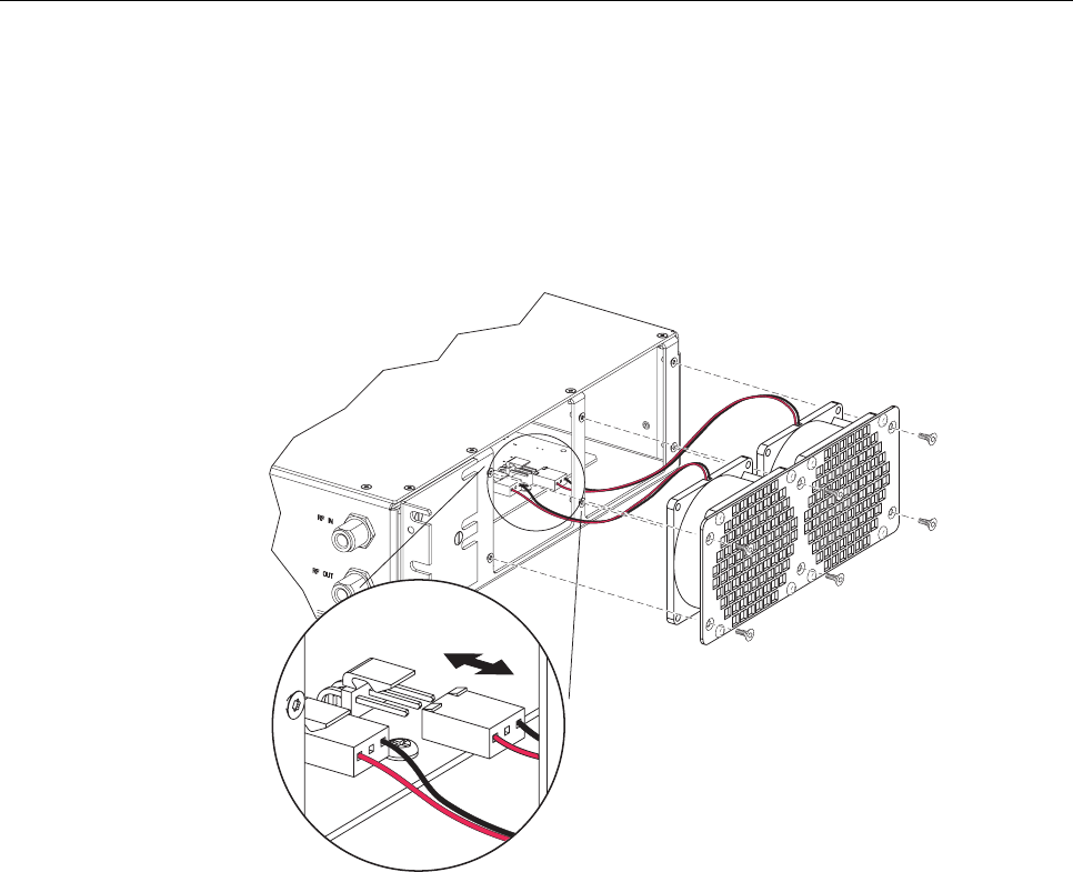
5. Remove the six flat-head screws (requires TORX screwdriver with T15 bit) that secure the
fan/grill assembly to the side of the enclosure as shown in Figure 31 and save for reuse.
16172-B
Figure 31. Fan/Grill Assembly Removal
6. Carefully withdraw the fan/grill assembly from the enclosure until the wiring harness is
exposed and the connectors are accessible.
7. Lift the small latch on each wiring harness connector (see Figure 31) and carefully
unplug each connector from the circuit board connector.
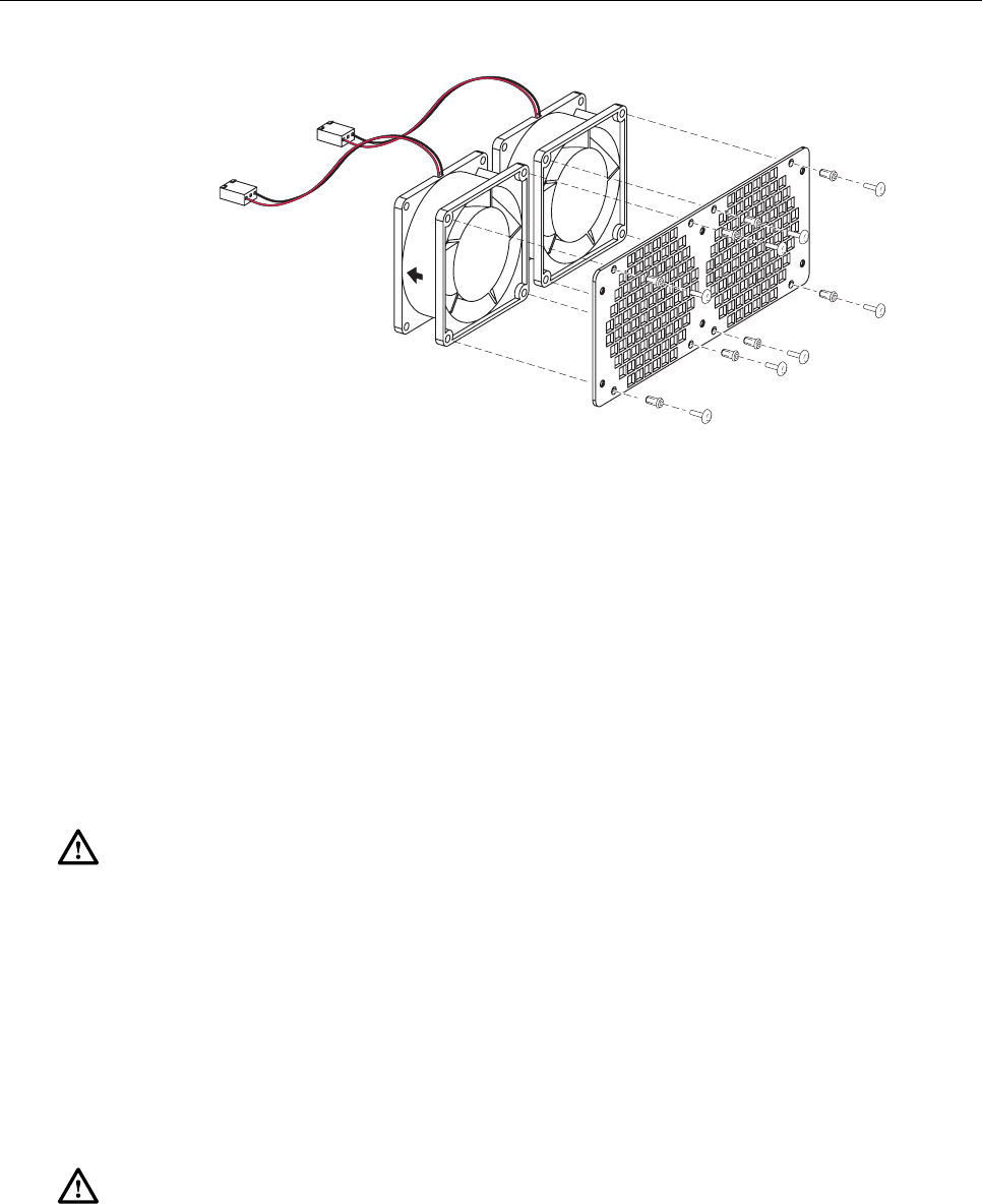
8. Remove the four plastic rivets that secure the faulty fan to the grill by pushing outward
on rivet center post until the rivet can be withdrawn from the grill as shown in Figure 32.
9. Remove the faulty fan(s) from the grill and then locate the replacement fan(s).
10. Use the rivets removed in step 8 to secure the replacement fan to the grill. Orient the fan so
the wiring harness is on the top and the arrow on the fan housing faces into the enclosure.
11. Connect the two wiring harness connectors to the circuit board connectors.
12. Secure the fan/grill assembly to the side of the enclosure (see Figure 31) using the six
flat-head screws removed in step 5.
ADCP-75-132 • Issue 2C • August 2006
Page 60
© 2006, ADC Telecommunications, Inc.
16173-B
Figure 32. Removing Fan From Grill
13. Place the DHU or DEU AC power On/Off switch in the ON position (press I).
14. Verify that the fans run properly following power up.
15. Notify the NOC or alarm monitoring system operator that the system is going back
online.
6.6 DHU or DEU Modular Optical Transceiver Replacement Procedure
The modular optical transceiver should be replaced when testing indicates that the transceiver
has failed. Use the following procedure to replace an optical transceiver in a DHU or DEU:
Danger: This equipment uses a Class 1 Laser according to FDA/CDRH rules. Laser
radiation can seriously damage the retina of the eye. Do not look into the ends of any optical
fiber. Do not look directly into the optical transceiver of any digital unit or exposure to laser
radiation may result. An optical power meter should be used to verify active fibers. A
protective cap or hood MUST be immediately placed over any radiating transceiver or optical
fiber connector to avoid the potential of dangerous amounts of radiation exposure. This
practice also prevents dirt particles from entering the transceiver or connector.
1. Put on the IR filtering safety glasses.
2. Slip on an Electro-Static Discharge (ESD) wrist strap and connect the ground wire to an
earth ground source such as the grounding stud on the DHU or DEU front panel. Wear
the ESD wrist strap while completing the optical transceiver replacement procedure.
Warning: Electronic components can be damaged by static electrical discharge. To prevent
ESD damage, always wear an ESD wrist strap when handling electronic components.
3. Place the PORT ON/OFF switch for the optical transceiver being replaced in the OFF
position (press O).
ADCP-75-132 • Issue 2C • August 2006
Page 61
© 2006, ADC Telecommunications, Inc.
Note: The HOST PORT on the DEU does not have an On/Off switch and can only be
disabled by placing the DEU AC power On/Off switch in the OFF position (press O).
Turning off the power to the DEU will create an alarm condition. If the DEU must be turned
off, inform the NOC or alarm monitoring system operator that an alarm will be reported.
4. Disconnect the optical fiber connectors from the optical transceiver and place a dust cap
over each connector.
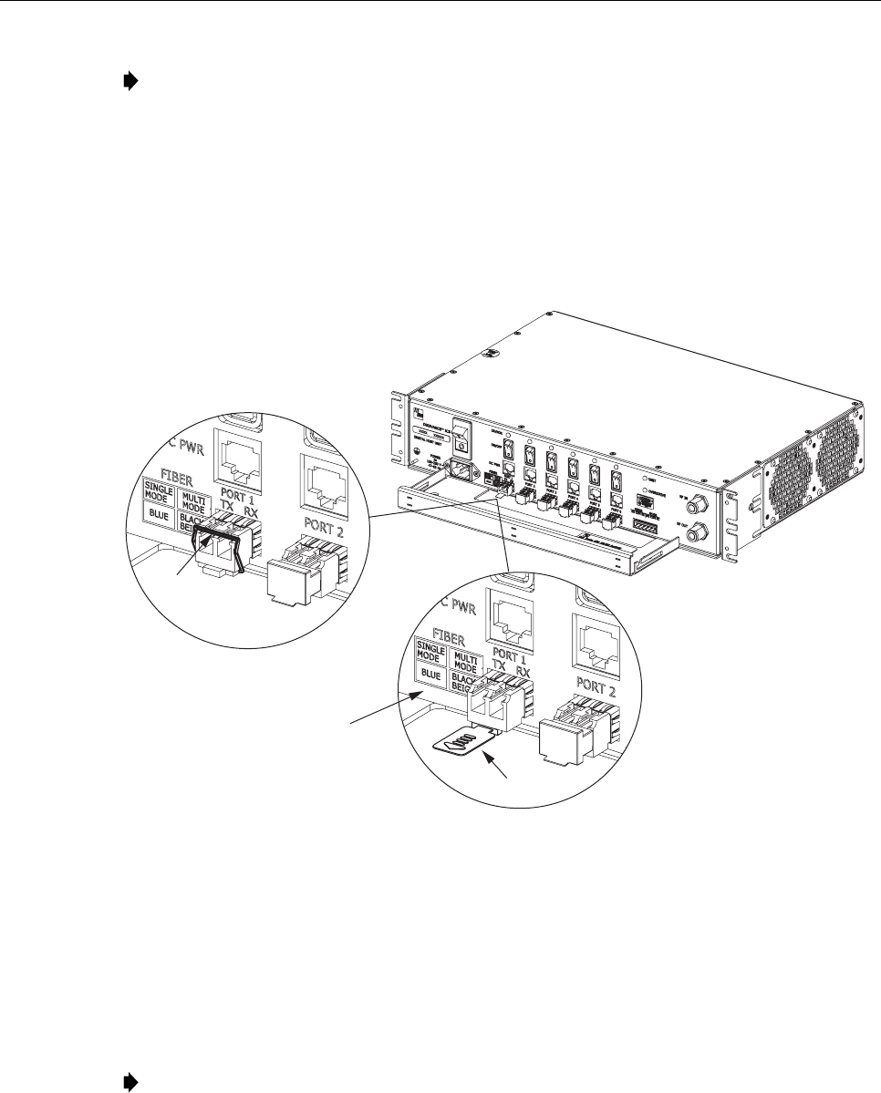
5. Release the optical transceiver from the transceiver socket by pulling outward on the
release lever (if type A) or release tab (if type B) as shown in Figure 33.
TYPE A
TRANSCEIVER
TYPE B
TRANSCEIVER
17283-A
RELEASE TAB
RELEASE
LEVER
TRANSCEIVER COLOR CODE
BLUE = SINGLE-MODE (9 MICRON)
BLACK/
BEIGE = MULTI-MODE (50 OR 62.5 MICRON)
Figure 33. DHU or DEU Optical Transceiver Removal
6. Remove the optical transceiver from the transceiver socket.
7. For replacement, select an optical transceiver that corresponds to the type of fiber
(single- or multi-mode) used in the installation. The color of the transceiver corresponds
to the transceiver fiber type (see Figure 33).
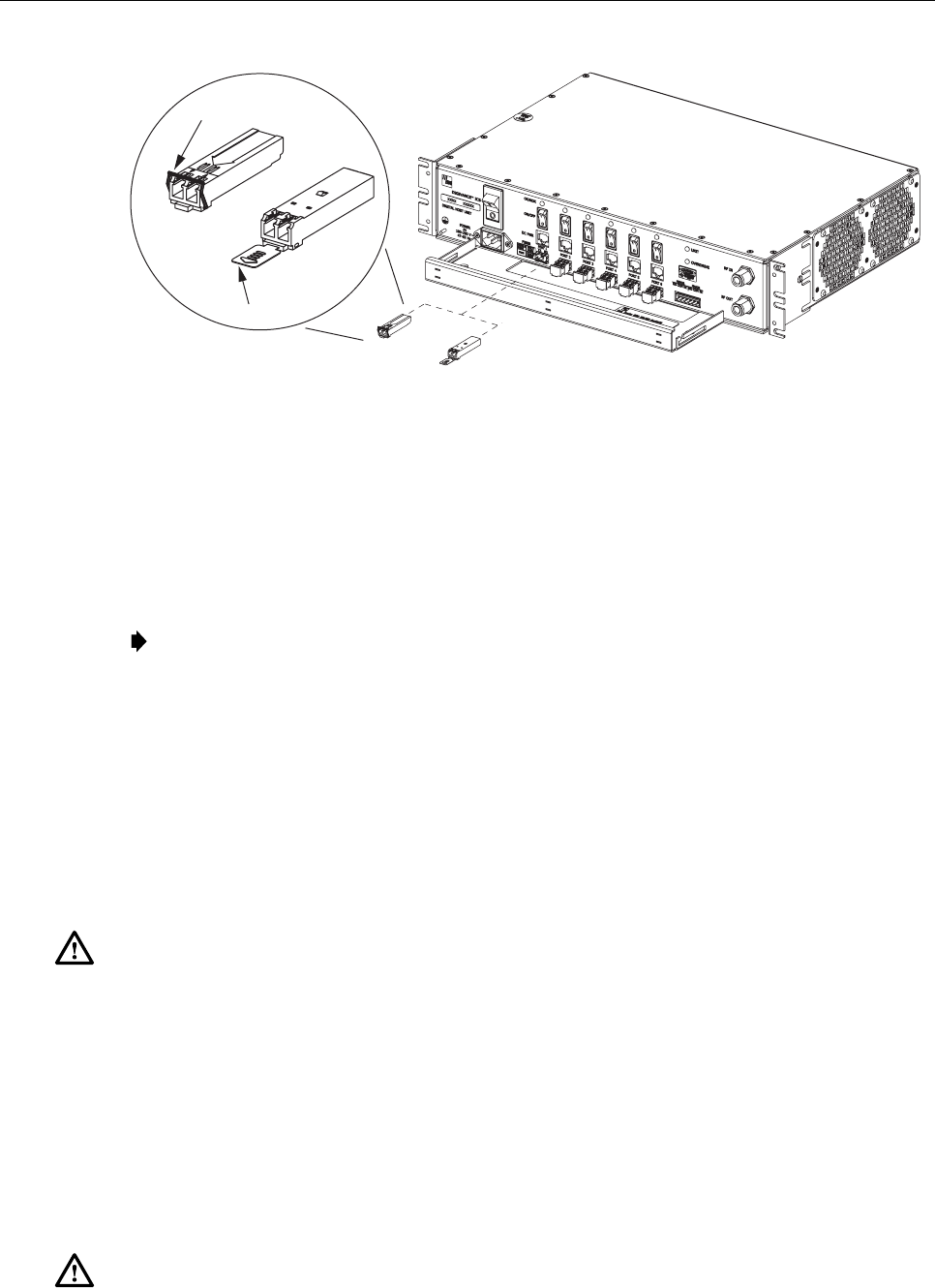
8. Remove the optical transceiver from the anti-static packaging and orient for installation
as shown in Figure 34.
Note: Two types of optical transceivers, type A and type B, are available. Both types
provide the same functionality. On the type A optical transceiver, the release lever (see
Figure 34) must be closed for installation.
ADCP-75-132 • Issue 2C • August 2006
Page 62
© 2006, ADC Telecommunications, Inc.
TXRX
DETAIL DRAWING
OF TYPE A AND TYPE B
MODULAR OPTICAL
TRANSCEIVERS
TX RX
TYPE A
TRANSCEIVER
TYPE B
TRANSCEIVER
RELEASE
LEVER
RELEASE TAB
17280-A
Figure 34. DHU or DEU Optical Transceiver Installation
9. Insert the optical transceiver into the socket until it locks into place.
10. Clean the optical fiber connectors and reconnect to the optical transceiver.
11. Place the PORT ON/OFF switch for the optical transceiver that was replaced in the ON
position (press I).
Note: If the DEU was turned off to replace the HOST PORT optical transceiver, place the
DEU AC power On/Off switch in the ON position (press I) and inform the NOC or alarm
monitoring system operator that the alarm has been cleared.
12. Verify that the DHU or DEU optical port LED indicators shown normal optical port
operation (refer to Table 7 or 8).
6.7 DRU Modular Optical Transceiver Replacement Procedure
The modular optical transceiver should be replaced when testing indicates that the transceiver
has failed. Use the following procedure to replace an optical transceiver in a DRU:
Danger: This equipment uses a Class 1 Laser according to FDA/CDRH rules. Laser
radiation can seriously damage the retina of the eye. Do not look into the ends of any optical
fiber. Do not look directly into the optical transceiver of any digital unit or exposure to laser
radiation may result. An optical power meter should be used to verify active fibers. A
protective cap or hood MUST be immediately placed over any radiating transceiver or optical
fiber connector to avoid the potential of dangerous amounts of radiation exposure. This
practice also prevents dirt particles from entering the transceiver or connector.
1. Put on the IR filtering safety glasses.
2. Slip on an Electro-Static Discharge (ESD) wrist strap and connect the ground wire to an
earth ground source. Wear the ESD wrist strap while completing the optical transceiver
replacement procedure.
Warning: Electronic components can be damaged by static electrical discharge. To prevent
ESD damage, always wear an ESD wrist strap when handling electronic components.
ADCP-75-132 • Issue 2C • August 2006
Page 63
© 2006, ADC Telecommunications, Inc.
3. Disconnect the DC power cable connector from the RJ-45 power jack on the DRU front
panel.
Note: Disconnecting the power from the DRU will create an alarm condition. Inform the
NOC or alarm monitoring system operator that the alarm will be reported.
4. Disconnect the optical fiber connectors from the optical transceiver and place a dust cap
over each connector.
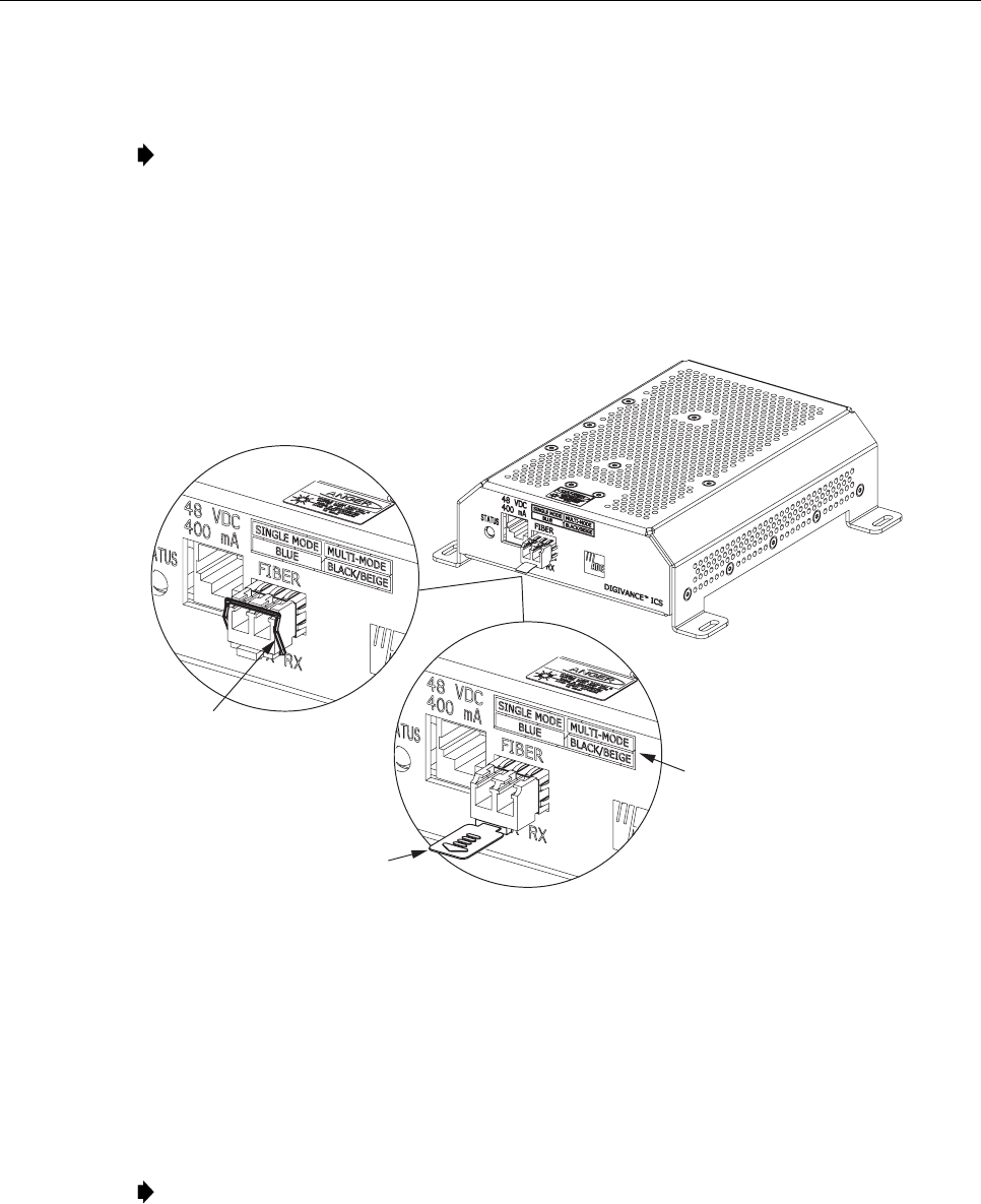
5. Release the optical transceiver from the transceiver socket by pulling outward on the
release lever (if type A) or release tab (if type B) as shown in Figure 35.
17285-A
TYPE A
TRANSCEIVER
TYPE B
TRANSCEIVER
RELEASE
LEVER
RELEASE TAB
TRANSCEIVER COLOR CODE
BLUE = SINGLE-MODE (9 MICRON)
BLACK/
BEIGE = MULTI-MODE (50 OR 62.5 MICRON)
Figure 35. DRU Optical Transceiver Removal
6. Remove the optical transceiver from the transceiver socket.
7. For replacement, select an optical transceiver that corresponds to the type of fiber
(single- or multi-mode) used in the installation. The color of the transceiver corresponds
to the fiber type (see Figure 35).
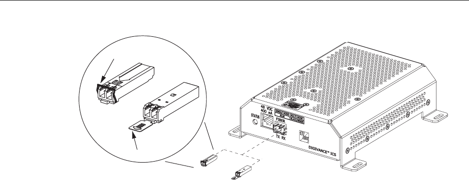
8. Remove the optical transceiver from the anti-static packaging and orient for installation
as shown in Figure 36.
Note: Two types of optical transceivers, type A and type B, are available. Both types
provide the same functionality. On the type A optical transceiver, the release lever (see
Figure 36) must be closed for installation.
ADCP-75-132 • Issue 2C • August 2006
Page 64
© 2006, ADC Telecommunications, Inc.
TXRX
DETAIL DRAWING
OF TYPE A AND TYPE B
MODULAR OPTICAL
TRANSCEIVERS
TXRX
TYPE A
TRANSCEIVER
TYPE B
TRANSCEIVER
RELEASE
LEVER
RELEASE TAB
17286-A
Figure 36. DRU Optical Transceiver Installation
9. Insert the optical transceiver into the socket until it locks into place.
10. Clean the optical fiber connectors and reconnect to the optical transceiver.
11. Reconnect the DC power cable plug to the RJ-45 jack on the DRU front panel and inform
the NOC or alarm monitoring system operator that the alarm has been cleared.
12. Verify that the DRU LED indicator shows normal operation (refer to Table 9).

ADCP-75-132 • Issue 2C • August 2006
Page 65
© 2006, ADC Telecommunications, Inc.
7 GENERAL INFORMATION
7.1 Warranty/Software
The Product and Software warranty policy and warranty period for all ADC products is
published in ADC’s Warranty/Software Handbook. Contact the Technical Assistance Center
at 1-800-366-3891, extension 73476 (in U.S.A. or Canada) or 952-917-3476 (outside U.S.A.
and Canada) for warranty or software information or for a copy of the Warranty/Software
Handbook.
7.2 Software Service Agreement
ADC software service agreements for some ADC Products are available at a nominal fee. Contact
the Technical Assistance Center at 1-800-366-3891, extension 73476 (in U.S.A. or Canada) or 952-
917-3476 (outside U.S.A. and Canada) for software service agreement information.
7.3 Repair/Exchange Policy
All repairs of ADC Products must be done by ADC or an authorized representative. Any attempt
to repair or modify ADC Products without authorization from ADC voids the warranty.
If a malfunction cannot be resolved by the normal troubleshooting procedures, contact the
Technical Assistance Center at 1-800-366-3891, extension 73476 (in U.S.A. or Canada) or
952-917-3476 (outside U.S.A. and Canada). A telephone consultation can sometimes resolve a
problem without the need to repair or replace the ADC Product.
If, during a telephone consultation, ADC determines the ADC Product needs repair, ADC will
authorize the return of the affected Product for repair and provide a Return Material
Authorization number and complete shipping instructions. If time is critical, ADC can arrange
to ship the replacement Product immediately. In all cases, the defective Product must be
carefully packed and returned to ADC.

ADCP-75-132 • Issue 2C • August 2006
Page 66
© 2006, ADC Telecommunications, Inc.
7.4 Repair Charges
If the defect and the necessary repairs are covered by the warranty, and the applicable
warranty period has not expired, the Buyer’s only payment obligation is to pay the shipping
cost to return the defective Product. ADC will repair or replace the Product at no charge and
pay the return shipping charges.
Otherwise, ADC will charge a percentage of the current Customer Product price for the repair
or NTF (No Trouble Found). If an advance replacement is requested, the full price of a new
unit will be charged initially. Upon receipt of the defective Product, ADC will credit Buyer
with 20 percent of full price charged for any Product to be Out-of-Warranty. Products must be
returned within (30) days to be eligible for any advance replacement credit. If repairs
necessitate a visit by an ADC representative, ADC will charge the current price of a field visit
plus round trip transportation charges from Minneapolis to the Buyer’s site.
7.5 Replacement/Spare Products
Replacement parts, including, but not limited to, button caps and lenses, lamps, fuses, and patch
cords, are available from ADC on a special order basis. Contact the Technical Assistance Center
at 1-800-366-3891, extension 73476 (in U.S.A. or Canada) or 952-917-3476 (outside U.S.A. and
Canada) for additional information.
Spare products and accessories can be purchased from ADC. Contact Sales Administration at
1-800-366-3891, extension 73000 (in U.S.A. or Canada) or 952-938-8080 (outside U.S.A. and
Canada) for a price quote and to place your order.
7.6 Returned Material
Contact the ADC Product Return Department at 1-800-366-3891, extension 73748 (in U.S.A.
or Canada) or 952-917-3748 (outside U.S.A. and Canada) to obtain a Return Material
Authorization number prior to returning an ADC Product.
All returned Products must have a Return Material Authorization (RMA) number clearly
marked on the outside of the package. The Return Material Authorization number is valid for
90 days from authorization.
ADCP-75-132 • Issue 2C • August 2006
Page 67
7.7 Customer Information and Assistance
13944-M
WRITE:
ADC TELECOMMUNICATIONS, INC
PO BOX 1101,
MINNEAPOLIS, MN 55440-1101, USA
ADC TELECOMMUNIC ATIONS (S'PORE) PTE. LTD.
100 BEACH ROAD, #18-01, SHAW TOWERS.
SINGAPORE 189702.
ADC EUROPEAN CUSTOMER SERVICE, INC
BELGICASTRAAT 2,
1930 ZAVENTEM, BELGIUM
PHONE:
EUROPE
Sales Administration: +32-2-712-65 00
Technical Assistance: +32-2-712-65 42
EUROPEAN TOLL FREE NUMBERS
UK: 0800 960236
Spain: 900 983291
France: 0800 914032
Germany: 0180 2232923
U.S.A. OR CANADA
Sales: 1-800-366-3891 Extension 73000
Technical Assistance: 1-800-366-3891
Connectivity Extension 73475
Wireless Extension 73476
ASIA/PACIFIC
Sales Administration: +65-6294-9948
Technical Assistance: +65-6393-0739
ELSEWHERE
Sales Administration: +1-952-938-8080
Technical Assistance: +1-952-917-3475
Italy: 0800 782374
PRODUCT INFORMATION AND TECHNICAL ASSISTANCE:
Contents herein are current as of the date of publication. ADC reserves the right to change the contents without prior notice.
In no event shall ADC be liable for any damages resulting from loss of data, loss of use, or loss of profits and ADC further
disclaims any and all liability for indirect, incidental, special, consequential or other similar damages. This disclaimer of
liability applies to all products, publications and services during and after the warranty period. This pu blication may be
verified at any time by contacting ADC's Technical Assistance Center.
euro.tac@adc.com
asiapacific.tac@adc.com
wireless.tac@adc.com
connectivity.tac@adc.com
© 2006, ADC Telecommunications, Inc.
All Ri
g
hts Reserved

i
www.adc.com