ADC Telecommunications DISSMRAA Digivance Indoor Coverage Solution System User Manual 75136 CV
ADC Telecommunications Inc Digivance Indoor Coverage Solution System 75136 CV
UserManual.wiki
>
ADC Telecommunications
>
DISSMRAA User Manual
>
manual 2
Contents
1.
manual 1
2.
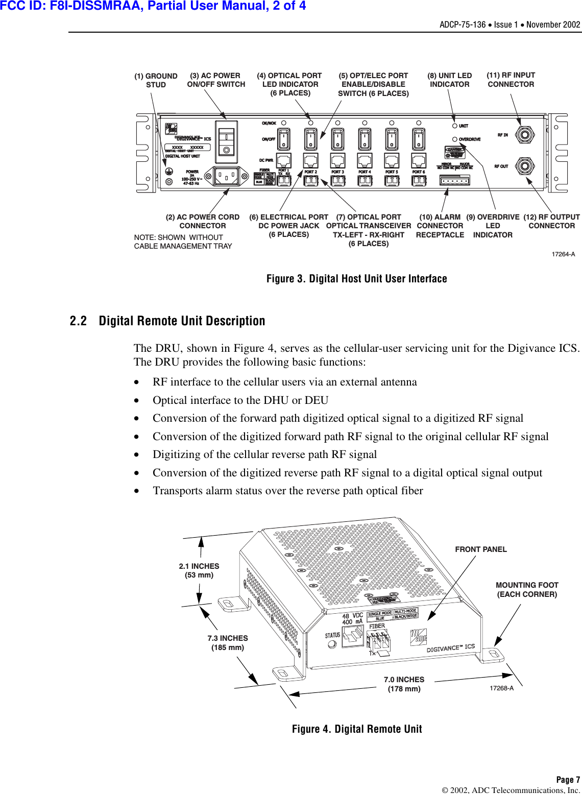
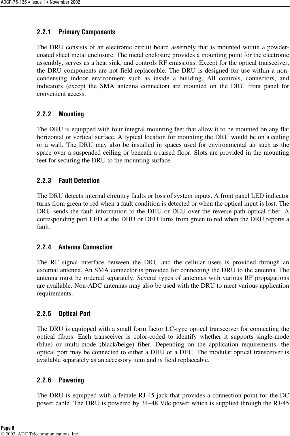
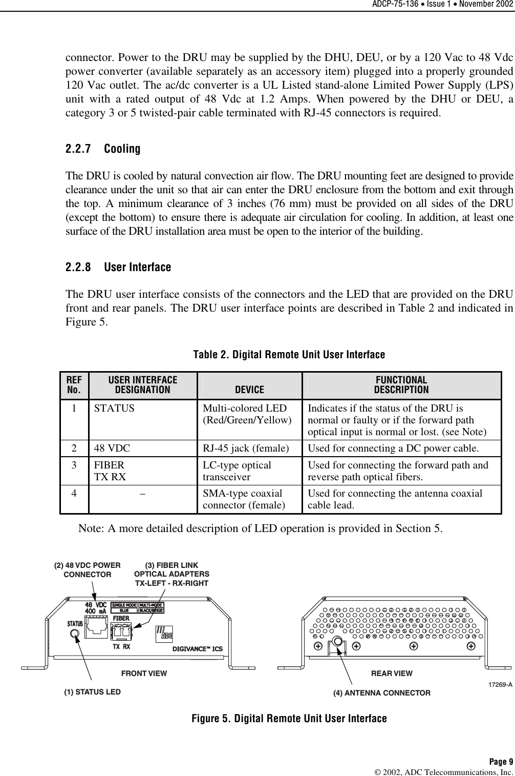
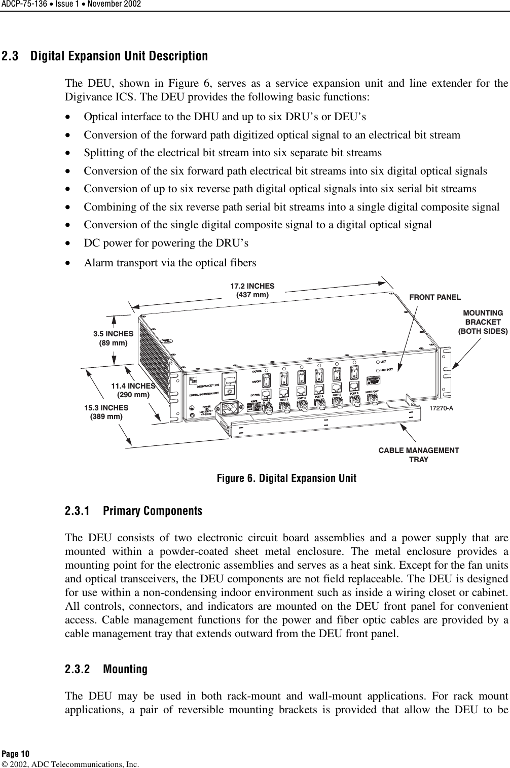
manual 2
3.
manual 3
4.
manual 4
manual 2
Navigation menu
Upload a User Manual
Namespaces
Wiki Guide
HTML
PDF
Info
Views
User Manual
Discussion / Help
Navigation