ADC Telecommunications DISSMRAA Digivance Indoor Coverage Solution System User Manual 75136 CV
ADC Telecommunications Inc Digivance Indoor Coverage Solution System 75136 CV
Contents
- 1. manual 1
- 2. manual 2
- 3. manual 3
- 4. manual 4
manual 2
ADCP-75-136 • Issue 1 • November 2002
Page 7
©2002, ADC Telecommunications, Inc.
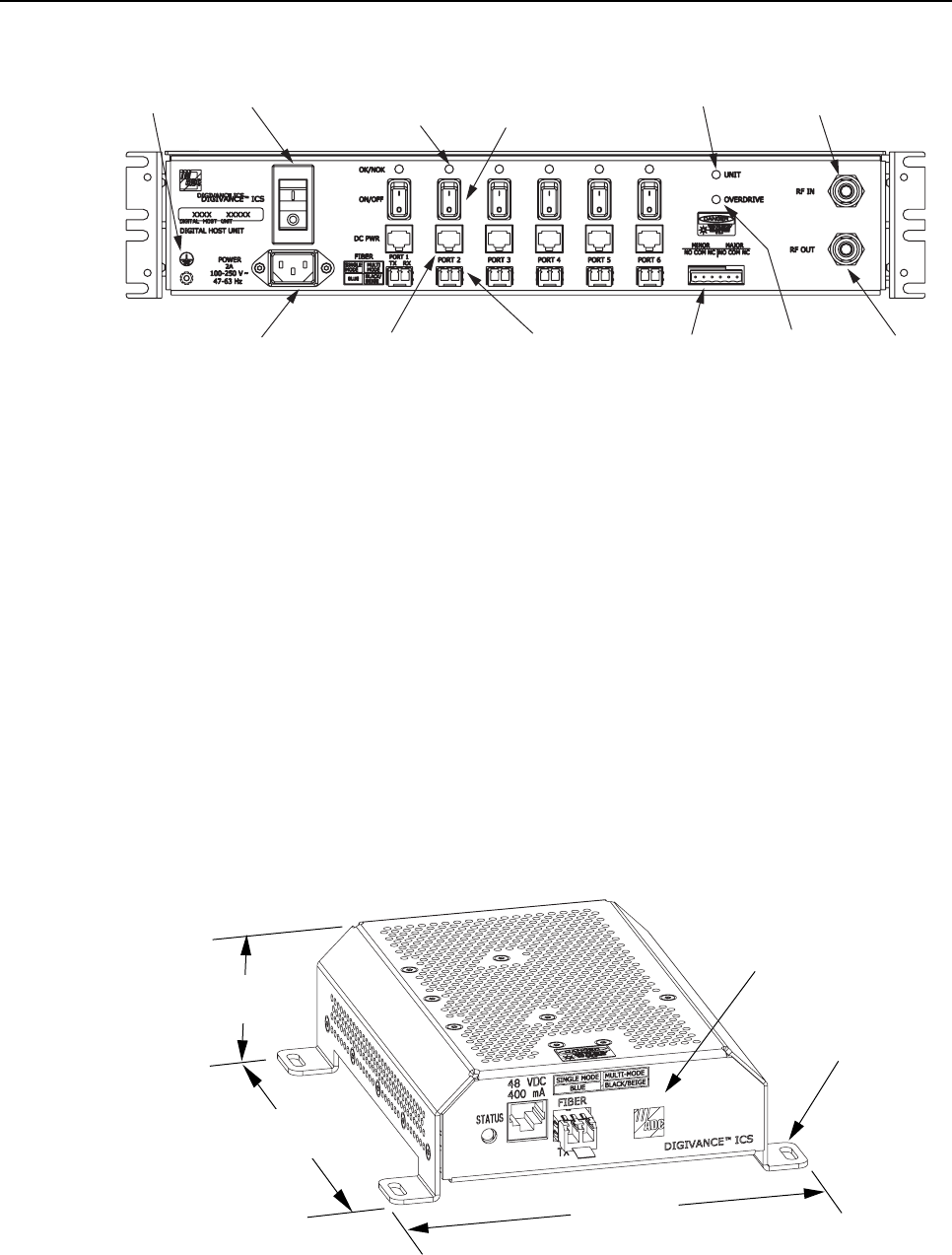
(2) AC POWER CORD
CONNECTOR
(3) AC POWER
ON/OFF SWITCH
(1) GROUND
STUD
(4) OPTICAL PORT
LED INDICATOR
(6 PLACES)
(5) OPT/ELEC PORT
ENABLE/DISABLE
SWITCH (6 PLACES)
(6) ELECTRICAL PORT
DC POWER JACK
(6 PLACES)
(7) OPTICAL PORT
OPTICAL TRANSCEIVER
TX-LEFT - RX-RIGHT
(6 PLACES)
(8) UNIT LED
INDICATOR
(11) RF INPUT
CONNECTOR
(9) OVERDRIVE
LED
INDICATOR
(10) ALARM
CONNECTOR
RECEPTACLE
(12) RF OUTPUT
CONNECTOR
17264-A
NOTE: SHOWN WITHOUT
CABLE MANAGEMENT TRAY
Figure 3. Digital Host Unit User Interface
2.2 Digital Remote Unit Description
The DRU, shown in Figure 4, serves as the cellular-user servicing unit for the Digivance ICS.
The DRU provides the following basic functions:
• RF interface to the cellular users via an external antenna
• Optical interface to the DHU or DEU
• Conversion of the forward path digitized optical signal to adigitized RF signal
• Conversion of the digitized forward path RF signal to the original cellular RF signal
• Digitizing of the cellular reverse path RF signal
• Conversion of the digitized reverse path RF signal to adigital optical signal output
• Transports alarm status over the reverse path optical fiber
FRONT PANEL
MOUNTING FOOT
(EACH CORNER)
7.0 INCHES
(178 mm)
7.3 INCHES
(185 mm)
2.1 INCHES
(53 mm)
17268-A
Figure 4. Digital Remote Unit
FCC ID: F8I-DISSMRAA, Partial User Manual, 2 of 4

ADCP-75-136 • Issue 1 • November 2002
Page 8
©2002, ADC Telecommunications, Inc.
2.2.1 Primary Components
The DRU consists of an electronic circuit board assembly that is mounted within apowder-
coated sheet metal enclosure. The metal enclosure provides amounting point for the electronic
assembly, serves as aheat sink, and controls RF emissions. Except for the optical transceiver,
the DRU components are not field replaceable. The DRU is designed for use within a non-
condensing indoor environment such as inside abuilding. All controls, connectors, and
indicators (except the SMA antenna connector) are mounted on the DRU front panel for
convenient access.
2.2.2 Mounting
The DRU is equipped with four integral mounting feet that allow it to be mounted on any flat
horizontal or vertical surface. Atypical location for mounting the DRU would be on a ceiling
or a wall. The DRU may also be installed in spaces used for environmental air such as the
space over a suspended ceiling or beneath a raised floor. Slots are provided in the mounting
feet for securing the DRU to the mounting surface.
2.2.3 Fault Detection
The DRU detects internal circuitry faults or loss of system inputs. A front panel LED indicator
turns from green to red when afault condition is detected or when the optical input is lost. The
DRU sends the fault information to the DHU or DEU over the reverse path optical fiber. A
corresponding port LED at the DHU or DEU turns from green to red when the DRU reports a
fault.
2.2.4 Antenna Connection
The RF signal interface between the DRU and the cellular users is provided through an
external antenna. An SMA connector is provided for connecting the DRU to the antenna. The
antenna must be ordered separately. Several types of antennas with various RF propagations
are available. Non-ADC antennas may also be used with the DRU to meet various application
requirements.
2.2.5 Optical Port
The DRU is equipped with asmall form factor LC-type optical transceiver for connecting the
optical fibers. Each transceiver is color-coded to identify whether it supports single-mode
(blue) or multi-mode (black/beige) fiber. Depending on the application requirements, the
optical port may be connected to either aDHU or a DEU. The modular optical transceiver is
available separately as an accessory item and is field replaceable.
2.2.6 Powering
The DRU is equipped with afemale RJ-45 jack that provides aconnection point for the DC
power cable. The DRU is powered by 34–48 Vdc power which is supplied through the RJ-45
ADCP-75-136 • Issue 1 • November 2002
Page 9
©2002, ADC Telecommunications, Inc.
connector. Power to the DRU may be supplied by the DHU, DEU, or by a 120 Vac to 48 Vdc
power converter (available separately as an accessory item) plugged into a properly grounded
120 Vac outlet. The ac/dc converter is aUL Listed stand-alone Limited Power Supply (LPS)
unit with arated output of 48 Vdc at 1.2 Amps. When powered by the DHU or DEU, a
category 3 or 5 twisted-pair cable terminated with RJ-45 connectors is required.
2.2.7 Cooling
The DRU is cooled by natural convection air flow. The DRU mounting feet are designed to provide
clearance under the unit so that air can enter the DRU enclosure from the bottom and exit through
the top. Aminimum clearance of 3inches (76 mm) must be provided on all sides of the DRU
(except the bottom) to ensure there is adequate air circulation for cooling. In addition, at least one
surface of the DRU installation area must be open to the interior of the building.
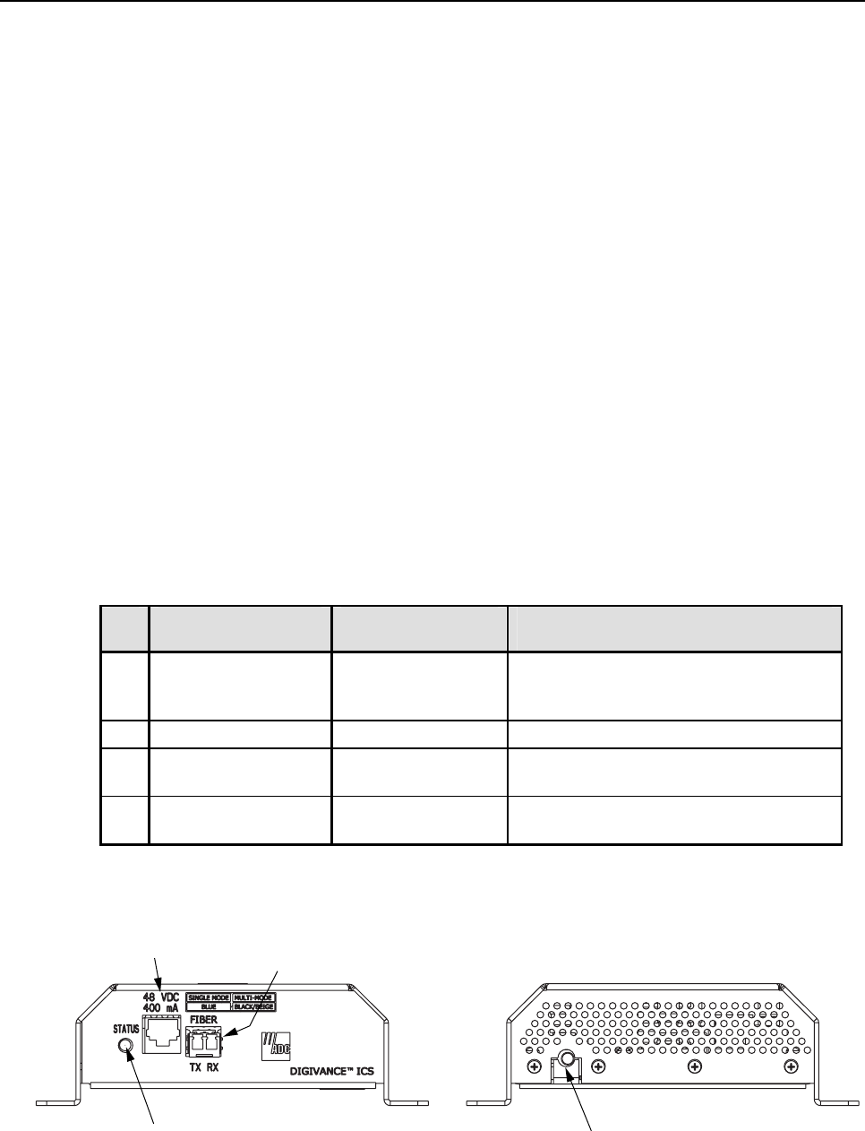
2.2.8 User Interface
The DRU user interface consists of the connectors and the LED that are provided on the DRU
front and rear panels. The DRU user interface points are described in Table 2 and indicated in
Figure 5.
Table 2. Digital Remote Unit User Interface
REF
No.
USER INTERFACE
DESIGNATION
DEVICE
FUNCTIONAL
DESCRIPTION
1STATUS Multi-colored LED
(Red/Green/Yellow) Indicates if the status of the DRU is
normal or faulty or if the forward path
optical input is normal or lost. (see Note)
2 48 VDC RJ-45 jack (female) Used for connecting a DC power cable.
3FIBER
TX RX LC-type optical
transceiver Used for connecting the forward path and
reverse path optical fibers.
4 – SMA-type coaxial
connector (female) Used for connecting the antenna coaxial
cable lead.
Note: Amore detailed description of LED operation is provided in Section 5.
17269-A
REAR VIEWFRONT VIEW
(4) ANTENNA CONNECTOR
(1) STATUS LED
(2) 48 VDC POWER
CONNECTOR
(3) FIBER LINK
OPTICAL ADAPTERS
TX-LEFT - RX-RIGHT
Figure 5. Digital Remote Unit User Interface
ADCP-75-136 • Issue 1 • November 2002
Page 10
©2002, ADC Telecommunications, Inc.
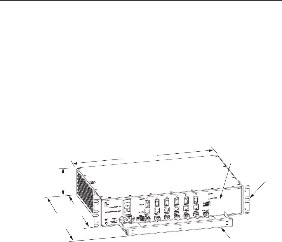
2.3 Digital Expansion Unit Description
The DEU, shown in Figure 6, serves as aservice expansion unit and line extender for the
Digivance ICS. The DEU provides the following basic functions:
• Optical interface to the DHU and up to six DRU’s or DEU’s
• Conversion of the forward path digitized optical signal to an electrical bit stream
• Splitting of the electrical bit stream into six separate bit streams
• Conversion of the six forward path electrical bit streams into six digital optical signals
• Conversion of up to six reverse path digital optical signals into six serial bit streams
• Combining of the six reverse path serial bit streams into asingle digital composite signal
• Conversion of the single digital composite signal to adigital optical signal
• DC power for powering the DRU’s
• Alarm transport via the optical fibers
FRONT PANEL
CABLE MANAGEMENT
TRAY
MOUNTING
BRACKET
(BOTH SIDES)
17270-A
3.5 INCHES
(89 mm)
11.4 INCHES
(290 mm)
15.3 INCHES
(389 mm)
17.2 INCHES
(437 mm)
Figure 6. Digital Expansion Unit
2.3.1 Primary Components
The DEU consists of two electronic circuit board assemblies and apower supply that are
mounted within apowder-coated sheet metal enclosure. The metal enclosure provides a
mounting point for the electronic assemblies and serves as aheat sink. Except for the fan units
and optical transceivers, the DEU components are not field replaceable. The DEU is designed
for use within anon-condensing indoor environment such as inside awiring closet or cabinet.
All controls, connectors, and indicators are mounted on the DEU front panel for convenient
access. Cable management functions for the power and fiber optic cables are provided by a
cable management tray that extends outward from the DEU front panel.
2.3.2 Mounting
The DEU may be used in both rack-mount and wall-mount applications. For rack mount
applications, apair of reversible mounting brackets is provided that allow the DEU to be

ADCP-75-136 • Issue 1 • November 2002
Page 11
©2002, ADC Telecommunications, Inc.
mounted in either a19-inch or 23-inch EIA or WECO equipment rack. When rack-mounted,
the front panel of the DEU is flush with the front of the rack and the cable management tray
extends 3.9 inches (99 mm) beyond the front panel. For wall-mount applications, apair of
holes is provided in the cable management tray which allow the DEU to be mounted on any
flat vertical surface. The DEU should be oriented with the front panel facing upward when
wall-mounted. Fasteners are provided for rack-mount applications.
2.3.3 Fault Detection
The DEU detects internal circuitry faults or loss of system inputs. Various front panel Light
Emitting Diode (LED) indicators turn from green to red or yellow when afault is detected or
when an optical input is lost. The DEU transports the fault information to the DHU or
supporting DEU over the reverse path optical fiber. Acorresponding port LED at the DHU or
DEU turns from green to red when the DEU reports afault.
2.3.4 Optical and Electrical Connections
The optical and electrical connections with the DRU’s and DEU’s are supported by six optical and
six electrical ports. Each optical and electrical port includes astatus LED, asmall form factor LC
type optical transceiver, an RJ-45 DC power jack, and aport enable/disable switch. Each transceiver
is color-coded to identify whether it supports single-mode (blue) or multi-mode (black/beige) fiber.
An optical port may be connected to aDRU, aDEU, or not used. An electrical port may be
connected to aDRU or not used. Unused ports are disabled via the corresponding port
enable/disable switch. When disabled, the port LED is off, the alarm reporting function is disabled,
the laser is off, and the DC power is off. Enabling the enable/disable switch activates all functions.
The DEU also provides one optical port (designated as the host port )for the optical interface with
the DHU or asupporting DEU. The modular optical transceivers are available separately as
accessory items and are field replaceable.
2.3.5 Powering
The DEU is powered by 120–240 Vac (50–60 Hz) power which is supplied though astandard
three-conductor AC power cord. The power cord is provided with the DEU and is 98 inches
(2.5 meters) long. Aresetable circuit breaker/On-Off switch is provided at the unit front panel.
The switch applies power to the DEU internal power supply.
2.3.6 Cooling
Continuous air flow for cooling is provided by dual fans mounted on the right side of the sheet
metal housing. Aminimum of 3 inches (76 mm) of clearance space must be provided on both
the left and right sides of the DEU for air intake and exhaust. An alarm is provided that
indicates if ahigh temperature condition (>50º C/122º F) occurs. The fans may be field-
replaced if either unit fails.
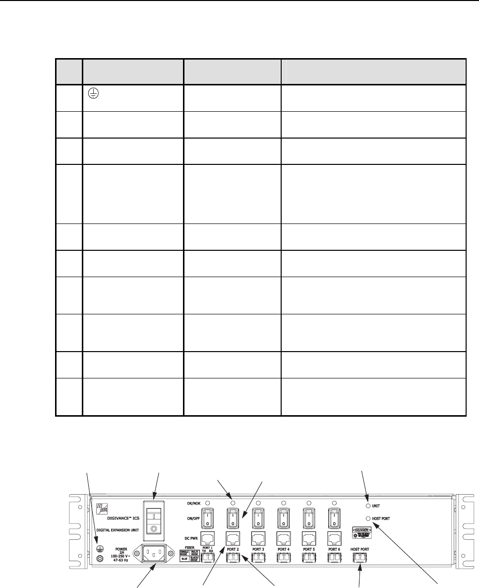
2.3.7 User Interface
The DEU user interface consists of the various connectors, switches, and LEDs that are
provided on the DEU front panel. The DEU user interface points are described in Table 3 and
indicated in Figure 7.
ADCP-75-136 • Issue 1 • November 2002
Page 12
©2002, ADC Telecommunications, Inc.
Table 3. Digital Expansion Unit User Interface
REF
No.
USER INTERFACE
DESIGNATION
DEVICE
FUNCTIONAL
DESCRIPTION
1Grounding stud Used for connecting a grounding cable to
the DEU chassis.
2POWER 3-wire AC power
cord connector Used for connecting the AC power cord.
3I/O I/O rocker switch/
circuit breaker Provides AC power On/Off control and
AC power over current protection.
4OK/NOK (Ports 1–6) Multi-colored LED
(Red/Green/Yellow) Indicates if the DRU or remote DEU
connected to the optical port is normal or
faulty or if the reverse path optical input
from the DRU or remote DEU is normal
or lost. (see Note)
5ON/OFF (Ports 1–6) I/O rocker switch Enables or disables corresponding
electrical and optical ports.
6DC PWR (Ports 1–6) RJ-45 jack (female) Used for connecting aDRU cat 3or 5power
cable to the designated DC power jack.
7FIBER (Ports 1–6) LC-type optical
transceiver Used for connecting each DRU or remote
DEU forward path and reverse path optical
fiber to the designated optical port.
8HOST PORT LC-type optical
transceiver Used for connecting the DHU or supporting
DEU forward path and reverse path optical
fiber.
9UNIT Multi-colored LED
(Red/Green/Yellow) Indicates if the DEU is normal or faulty.
(see Note)
10 HOST PORT Multi-colored LED
(Red/Green/Yellow) Indicates if the forward path optical input
from the DHU or supporting DEU is
normal or lost. (see Note)
Note: A more detailed description of LED operation is provided in Section 5.
17266-A
(3) AC POWER
ON/OFF SWITCH
(1) GROUNDING
STUD
(4) OPTICAL PORT
LED INDICATOR
(6 PLACES)
(5) OPT/ELEC PORT
ENABLE/DISABLE
SWITCH (6 PLACES)
(9) UNIT LED
INDICATOR
(2) AC POWER CORD
CONNECTOR
(6) ELECTRICAL PORT
DC POWER JACK
(6 PLACES)
(7) OPTICAL PORT
OPTICAL TRANSCEIVER
TX-LEFT - RX-RIGHT
(6 PLACES)
(10) HOST PORT
LED
INDICATOR
(8) HOST PORT
OPTICAL TRANSCEIVER
TX-LEFT - RX-RIGHT
NOTE: SHOWN WITHOUT
CABLE MANAGEMENT TRAY
Figure 7. Digital Expansion Unit User Interface

ADCP-75-136 • Issue 1 • November 2002
Page 13
©2002, ADC Telecommunications, Inc.
2.4 Terms and Definitions
Refer to Table 4 for alisting of the terms used in this manual and their definition.
Table 4. Terms and Definitions
TERM DEFINITION
Alarm Response The response to an alarm input.
Base Transceiver Station The radio equipment that transmits and receives the voice and control
channels to and from the cellular handsets.
Composite Signal A signal that is the sum of several signals.
Digital Expansion Unit The unit that extends a single optical interface to multiple optical
interfaces or that extends an optical run.
Digital Host Unit The unit that converts and provides the digital source signal to all DEU’s
and DRU’s and converts summed inputs from DEU’s and DRU’s.
Digital Remote Unit The unit that interfaces the in-building user to the Digivance optical
transport.
Digitized RF Signal The RF signal in a digitized form.
Forward Path Signal A signal that travels from the base station to the cell phone.
Major Alarm An alarm condition that applies when any fault (except high
temperature) occurs.
Minor Alarm The alarm condition that applies when a high temperature condition
occurs. (> 50º C/122º F)
Mute To force aforward path RF signal to a“no signal” state.
Normal State The operating state after power-up is completed and no faults are
detected.
Port An RF, optical, or electrical interface point.
Port Alarm Afault that affects only the unit or units connected to that port.
Indicates no optical input to port.
Power-Up State The period between the application of power to a unit and the normal
state. This period includes time for circuit stabilization and
initialization operations.
Reverse Path Signal A signal that travels from one or more cell phones to the base station.
Transport Alarm Signal An alarm signal transported over the reverse path optical fiber.
Unit Alarm Afault within a unit that usually affects all connected ports.
2.5 Specifications
Refer to Table 5 for the Digivance ICS system specifications. All specifications apply after a
five minute warm-up period.

ADCP-75-136 • Issue 1 • November 2002
Page 14
©2002, ADC Telecommunications, Inc.
Table 5. System Specifications
PARAMETER SPECIFICATION REMARKS
Optical – All Units
Fiber type Multi-mode: 50 or 62.5 micron core
Single-mode: 9micron core Two fibers per transport link
Maximum fiber length
for guaranteed
performance
500 m (1,641 ft)
750 m (2461 ft)
10 km (32,808 ft)
With 62.5 micron core MM fiber
With 50 micron core MM fiber
With 9micron core SM fiber
Optical output power –10 to –3 dBm
Optical wavelength 850 nm for multi-mode use
1310 nm for single-mode use
Environmental
Operating temperature 0º to 50º C (32º to 122º F)
Storage temperature –30º to +70º C (–22 to 158º F)
Humidity No condensation
Weather resistance NEMA type 2, IEC 529 IP30 Indoor installation only
RF Forward Path
System bandwidth 18 MHz
Frequency range 851 to 869 MHz
Output power > +13 dBm Maximum composite power
Gain +33 dB nominal At room temperature
Gain variation < 6 dB
< 1.5 dB variation per 1.25 MHz
CDMA channel
Over frequency, temperature, and
unit to unit. May have up to 2 dB
variation at upper band edge.
OIP3 +35 dBm typical At max. composite output power
CDMA ACPR1 < –45 dBc
Spurious Output < –30 dBm
DHU RF input signal
level –20 dBm maximum composite Provides maximum output power
level at the DRU
RF Reverse Path
System bandwidth 18 MHz
Frequency range 806 to 824 MHz
Gain +10 dB nominal
Gain Variation < 6 dB
< 1.5 dB variation per 1.25 MHz
CDMA channel
Over frequency, temperature, and
unit to unit.
Automatic Gain Limiting Enabled for composite RF input
>–40 dBm Prevents A/D saturation with large
inputs.
Noise Figure < 9 dB + 10 log Nwhere N = # of
remotes < 9 dB typical. See Note at end of
table.
DHU RF output signal
level –30 dBm maximum With a–40 dBm composite
maximum input signal at the DRU
(continued)

ADCP-75-136 • Issue 1 • November 2002
Page 15
©2002, ADC Telecommunications, Inc.
Table 5. System Specifications, continued
PARAMETER SPECIFICATION REMARKS
Physical/Electrical – DHU
Weight 18.5 lbs (8.4 kg)
RF connection Type N Female
Alarm connection Screw terminals (14–26 AWG) NO, NC, and COM (form Crelay
contacts)
Optical connection Duplex LC transceiver
DC power output
connection RJ-45 Female
Power input 120/240 Vac, 50–60 Hz
AC power connection IEC 320 Male
Power consumption 250 W Maximum
Current rating 85–250 Vac, 2Amp input
Physical/Electrical – DEU
Weight 18.5 lbs (8.4 kg)
Optical connection Duplex LC transceiver
DC pwr output connection RJ-45 Female
Power input 120/240 Vac, 50–60 Hz
AC power connection IEC 320 Male
Power consumption 250 W Maximum
Current rating 85–250 Vac, 2Amp input
Physical/Electrical – DRU
Weight 1.5 lbs (708 g)
RF connection SMA Female
Antenna types Ceiling mount omni directional
90º directional panel
Ceiling mount hallway
2.5 dBi gain
7.5 dBi gain
4dBi gain
Optical connection Duplex LC transceiver
DC pwr input connection RJ-45 Female
Power input 34 to 48 Vdc
DC power cable length
(Cat-3 or -5 cable) 500 meters (1,641 ft) maximum Any distance beyond 500 meters
requires alternate power sourcing
Power consumption 17 W Typical
Current rating 48 Vdc, 400 mA input
Note:The noise from all remotes is added at the host. Given Nunits with identical gain and noise, the formula
applies exactly. Slight unit to unit noise figure and gain variations make this avery useful approximation.
ADCP-75-136 • Issue 1 • November 2002
Page 16
©2002, ADC Telecommunications, Inc.
3 INSTALLATION PLANNING AND SYSTEM DESIGN
This section provides installation planning information and basic system design recommendations
for RF engineers that will be designing and installing an in-building coverage solution using the
Digivance ICS. System design and planning services are available from ADC if required. Refer to
Section 7of this manual for additional information.
3.1 Base Station Interface Requirements
The DHU may be interfaced either locally or remotely with the BTS. As referenced in this
publication, the BTS could be either amicrocell or a cell site base station. With alocal
interface, ahard-wire connection is provided between the DHU and the BTS (microcell) using
coaxial cables. With aremote interface, an over-the-air connection is provided between the
DHU and the BTS (cell site base station) using a donor antenna.
3.1.1 Local BTS (Microcell) Interface
Alocal interface between the DHU and the BTS (microcell) over coax requires specific RF
input and output signal levels at the DHU and BTS. The correct levels must be provided at the
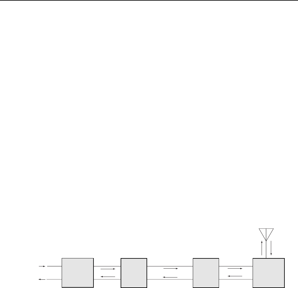
BTS and DHU interface using alocal interface device (ancillary product). Ablock diagram of
atypical local BTS interface is shown in Figure 8.
LOCAL
INTERFACE
DEVICE
(ANCILLARY
PRODUCTS)
FORWARD
(DOWNLINK)
REVERSE
(UPLINK)
+13 dBm
(COMPOSITE MAX)
-40 dBm
(COMPOSITE
MAX)
-20 dBm
(COMPOSITE MAX)
-30 dBm
(COMPOSITE MAX)
18110-A
DIGITAL
HOST
UNIT
OPTICAL LINK
OPTICAL LINK
DIGITAL
REMOTE
UNIT
DIRECTIONAL ANTENNA
TO/FROM HANDSETS
LOCAL BASE
TRANSCEIVER
STATION
(MICRO CELL)
T1 LINK
TO SWITCH
Figure 8. Local BTS Interface Block Diagram
The level of the RF output signal from the BTS varies depending on the type of BTS.
Therefore, it will generally be necessary to add some gain or some attenuation to the forward
path (downlink) signal. The recommended composite maximum RF input signal level at the
DHU is –20 dBm.When the level of the RF input signal at the DHU is –20 dBm, the level of
the RF output signal at the DRU will be +13 dBm.
In the reverse path, the input signal level required at the BTS also varies depending on the
type of BTS. When the level of the reverse path (uplink) signal at the DRU is at the
recommended composite maximum of –40 dBm,the level of the RF output signal from the
DHU will be –30 dBm.Therefore, it may also be necessary to add some gain or attenuation to
the reverse path signal in order to provide the input RF signal level required at the BTS.
ADCP-75-136 • Issue 1 • November 2002
Page 17
©2002, ADC Telecommunications, Inc.
3.1.2 Remote BTS (Cell Site Base Station) Interface
Aremote interface between the DHU and the BTS (cell site base station) via a donor antenna
requires specific RF input and output signal levels at the DHU and antenna. The correct levels
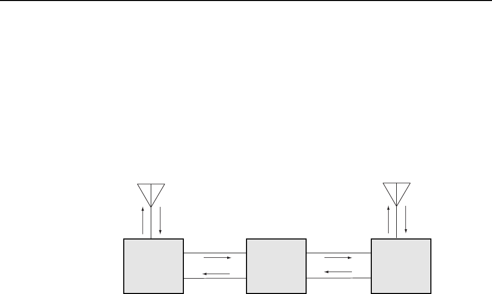
at the DHU and antenna can be provided using aremote interface device (ancillary product). A
block diagram of a typical remote DHU to BTS interface is shown in Figure 9.
DIRECTIONAL
ANTENNA TO/FROM
CELL SITE BTS
18111-A
REMOTE
INTERFACE
DEVICE
(ANCILLARY
PRODUCT)
FORWARD
(DOWNLINK)
REVERSE
(UPLINK) +13 dBm
(COMPOSITE
MAX)
-40 dBm
(COMPOSITE
MAX)-20 dBm
(COMPOSITE
MAX)
-30 dBm
(COMPOSITE
MAX)
DIGITAL
HOST
UNIT
OPTICAL LINK
OPTICAL LINK
DIGITAL
REMOTE
UNIT
DIRECTIONAL ANTENNA
TO/FROM HANDSETS
Figure 9. Remote BTS Interface Block Diagram
In the forward path (downlink), the recommended composite maximum RF input signal level
at the DHU is –20 dBm.When the level of the RF input signal at the DHU is –20 dBm, the
level of the RF output signal at the DRU will be +13 dBm.
In the reverse path, the RF output signal level required at the donor antenna will vary
depending on the distance from the BTS. When the level of the reverse path (uplink) signal at
the DRU is at the recommended composite maximum level of –40 dBm,the level of the RF
output signal from the DHU with be –30 dBm.Therefore, it will generally be necessary to add
some gain to the reverse path signal in order to provide the output RF signal level required at
the donor antenna.
3.2 Location and Mounting Requirements
3.2.1 DHU and DEU Location and Mounting Requirements
The DHU and the DEU may be either rack mounted or wall mounted. Fasteners (both metric and
US standard) are included with each unit for rack mount applications. Apair of reversible mounting
brackets is provided that allows the unit to be mounted in either a19-inch or 23-inch EIA or WECO
equipment rack. When rack-mounted, the front panel of the unit is flush with the front of the rack.
The cable management tray extends 3.9 inches (99 mm) beyond the front panel. Both the DHU and
DEU occupy 3.5 inches (89 mm) of rack space. Make sure the mechanical loading of the rack will
be even to avoid ahazardous condition such as aseverely unbalanced rack. The rack should safely
support the combined weight of all the equipment it holds and be properly anchored.

ADCP-75-136 • Issue 1 • November 2002
Page 18
©2002, ADC Telecommunications, Inc.
For wall-mount applications of the DHU or DEU, apair of holes is provided in the cable
management tray that allows the unit to be mounted on any flat vertical surface. The mounting
holes are spaced 11-21/32 inches (296 mm) apart. The DHU/DEU should be oriented so the
front panel faces up when mounted. Appropriate fasteners for wall mounting must be provided
by the installer. It is recommended that abacker board such as 3/4-inch plywood be installed
over the mounting surface to provide asecure base for attaching the DHU or DEU.
The DHU and DEU should be mounted in anon-condensing indoor environment such as
inside awiring closet or within an environmentally controlled cabinet. All controls,
connectors, and indicators are mounted on the front panel. All cables should be routed to the
front panel for connection. Cable retainers provided on the cable management tray for securing
the fiber optic, DC power, and external alarm system cables.
The maximum recommended ambient temperature for the DHU and DEU is 50º C (122º F).
Sufficient space for air circulation should be provided between each unit when installed in a
multi-unit rack assembly because the operating ambient temperature of the rack environment
might be greater than room ambient. Aminimum clearance of 3 inches (76 mm) should be
provided on both the left and right sides of the unit for air intake and exhaust. Refer to Figure
2for the DHU dimensions and Figure 6 for the DEU dimensions.
3.2.2 DRU Location and Mounting Requirements
The DRU must be installed in anon-condensing indoor environment and may be wall-
mounted or ceiling-mounted. The DRU may also be installed in spaces used for environmental
air such as the space over a suspended ceiling or beneath a raised floor. The DRU is equipped
with four integral mounting feet that allow it to be fastened to any flat vertical or horizontal
surface. Holes are provided in the mounting feet for inserting fasteners. Appropriate fasteners
for securing the DRU to the selected mounting surface must be provided by the installer.
The DC power cable and optical fibers should be routed to the DRU front panel for
connection. The antenna coaxial cable should be routed to the DRU rear panel for connection.
Aminimum of 3 inches (76 mm) of clearance space should be provided on all sides of the
DRU (except the bottom) to ensure there is adequate air circulation for cooling. In addition, at
least one surface of the DRU installation area must be open to the interior of the building. If a
portable/flexible antenna will be installed, aminimum of 9 inches (229 mm) clearance should
be allowed along the surface with the antenna. Refer to Figure 4 for the DRU dimensions.
3.3 Powering Requirements
3.3.1 DHU and DEU Powering
The DHU and DEU are powered by 120–240 Vac (50–60 Hz) which is supplied through a
standard three-conductor AC power cord. The 120 Vac power cord is provided with the unit
and is 98 inches (2.5 m) long. Both the DHU and the DEU have a current rating of 2.0 Amps
at 120 Vac input. Each unit should be located so that an AC outlet is within the reach of the
power cord.
ADCP-75-136 • Issue 1 • November 2002
Page 19
©2002, ADC Telecommunications, Inc.
If back-up powering is required, it is recommended that the building Uninterruptible Power Supply
(UPS) system be used to provide back-up power to the DHU and DEU in the event of an AC power
outage. This will also power all the DRU’s that are powered by the DHU or DEU.
3.3.2 DRU Powering
The DRU is powered by 48 Vdc power which is input to the DRU through the front panel RJ-
45 connector. Power to the DRU may be provided by the DHU, DEU, or by a 120 Vac to 48
Vdc power converter (available separately as an accessory item) plugged into a properly
grounded 120 Vac outlet. The DRU has a current rating of 400 mA at 48 Vdc input.
If the DRU will be powered by the DHU or DEU, the power cable must be fabricated on-site by the
installer. Category 3or 5twisted pair cable should be used for the power supply cable. The
maximum recommended length of the power cable is 500 meters.The power cable must be routed
between the DHU or DEU and the DRU. Both ends of the power cable must be terminated with a
male RJ-45 connector. If the DRU will be located more than 500 meters from the DHU or DRU, it
must be locally powered by a48 Vdc power converter.
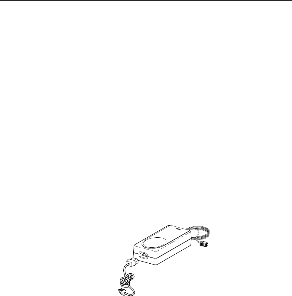
The DRU may be powered locally by the ac/dc converter, shown in Figure 10, which is
available as an accessory item. The converter is aUL Listed stand alone Limited Power
Supply (LPS) unit with arated output of 48 Vdc at 1.2 Amps.The converter is equipped with
a 6-foot (1.8 m) DC power cable which is terminated with an RJ-45 male connector. The
converter is powered by 120–240 Vac (50–60 Hz) power which is supplied though astandard
three-conductor AC power cord. The 120 Vac power cord is 6feet (1.8 m) long and is
provided with the converter.
15988-A
Figure 10. AC/DC Power Converter
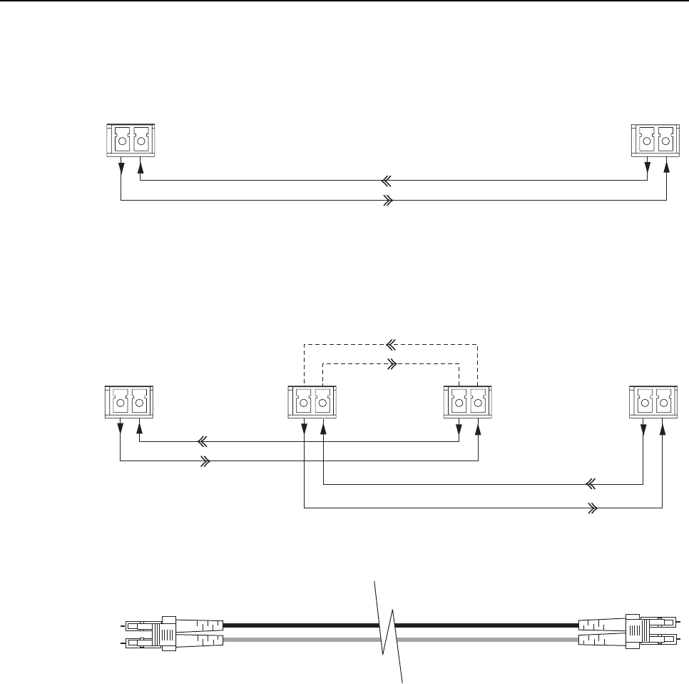
3.4 Optical Options and Requirements
Each DHU and its associated DEU’s and DRU’s are connected over a pair of optical fibers.
One fiber transports the forward path optical signal and the other fiber transports the reverse
path optical signal. Either 62.5 or 50 micron core multi-mode optical fiber; or 9 micron core
single-mode optical fiber may be used for the optical transport connection. With 62.5 micron
core fiber, the optical path may be up to 500 meters in length. With 50 micron core fiber, the
optical path may be up to 750 meters in length. With 9micron core cable, the optical path may
be up to 10 kilometers in length. Single- and multi-mode fibers may be used in the same
system. Adiagram of the optical connections is shown in Figure 11.
ADCP-75-136 • Issue 1 • November 2002
Page 20
©2002, ADC Telecommunications, Inc.
TX RX
TX RX
TX RX TX RX TX RX TX RX
PORTS 1-6
PORTS
1-6
PORTS 1-6
FIBER PORT
FIBER PORT
HOST
PORT
FORWARD PATH
REVERSE PATH
FORWARD PATH
REVERSE PATH
FORWARD PATH
REVERSE PATH
DIGITAL
REMOTE
UNIT
DIGITAL
REMOTE
UNIT
DIGITAL
HOST
UNIT
DIGITAL
HOST
UNIT
DIGITAL EXPANSION UNIT
BASIC CONFIGURATION WITH DHU AND DRU
BASIC CONFIGURATION WITH DHU, DEU, AND DRU
END-TO-END OPTICAL CONNECTOR/CABLE ASSEMBLY DIAGRAM
16814-A
62.5 MICRON: MAXIMUM LENGTH = 500 METERS
50 MICRON: MAXIMUM LENGTH = 750 METERS
9 MICRON: MAXIMUM LENGTH = 10 KILOMETERS
Figure 11. Digivance ICS Optical Connections
Whenever possible, use conduit or aguideway such as the FiberGuide system to route the optical
fibers between the DHU, the DEU’s, and the DRU’s. Avoid routing optical fibers through ladder
type cable racks or troughs that do not provide sufficient support to limit bending or prevent
accidental damage. Tie-wrapping is not recommended as ameans of securing fiber optic cables.
Provide sufficient slack at each unit for connecting each fiber to the required port. Fibers may be
pre-terminated or terminated on-site using field-installable LC type connectors.
3.5 Coaxial Cable Requirements
The DHU interfaces either locally (see Figure 8) or remotely (see Figure 9) with the BTS
through coaxial cable connections. In alocal interface with the BTS, coaxial cables are

ADCP-75-136 • Issue 1 • November 2002
Page 21
©2002, ADC Telecommunications, Inc.
required to link the DHU with the interface device and the interface device with the BTS. In a
remote interface, coaxial cables are required to link the DHU with the interface device and the
interface device with the donor antenna. The DHU is equipped with N-type female connectors
for connecting the forward and reverse path coaxial cables. High performance, flexible, low
loss 50-ohm coaxial communications cable (RG 400 or equivalent) should be used for all
coaxial connections.
3.6 System Expansion Planning
The DEU enables 6-way expansion of any optical port. This makes it possible to add more
DRU’s without having to install additional DHU’s. Each DHU is equipped with six optical
ports. If more than six DRU’s are required by the application, aDEU may be connected to one
of the optical ports at the DHU which expands that port to six ports. If still more optical ports
are required, then asecond DEU may be connected to the DHU or a second DEU may be
connected to the first DEU. The ability to cascade DEU’s in parallel or in series provides
unlimited flexibility. It is physically possible to connect an unlimited number DRU’s to the
DHU through the installation of DEU’s.
The total number of DRU’s that can be served is limited by the cumulative noise effect caused
by antenna combining. This number cannot be determined until the radius distance of
coverage required at the DRU antenna is determined and the path loss attributed to the
structure are known. The system design requires that the carrier to noise differential be greater
than the customer’s desired signal to noise ratio.
If it is likely that the system will be expanded in the future, locate the DHU in such away that it can
be used as ahub for an expanded system. It should be noted that aDEU can be used as an optical
regenerator. ADRU may sometimes need to be located at apoint that is beyond the distance
limitation imposed by the optical fiber. The solution is to install aDEU at the maximum optical
fiber length from the DHU. This provides an additional 500 m, 750 m, or 10 km (depending on the
fiber type) of optical fiber length beyond the DEU for connecting the DRU.
3.7 DRU Antenna Options
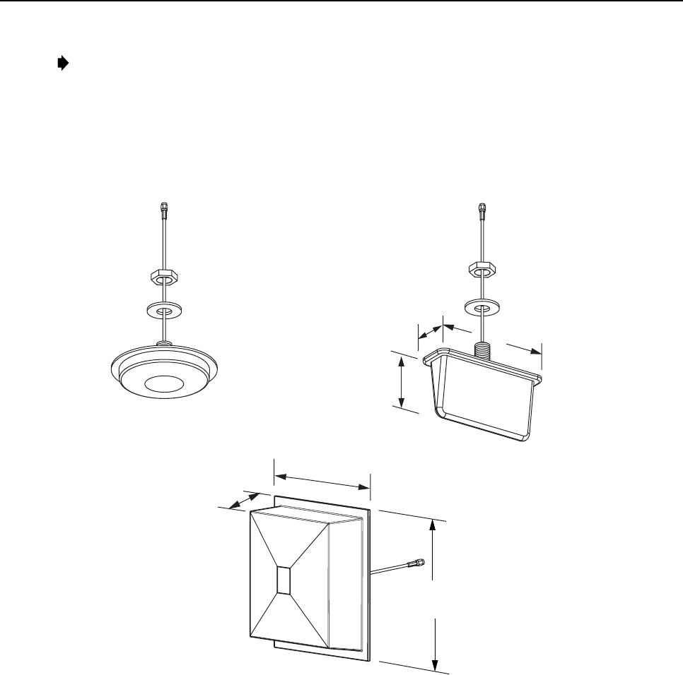
Various antennas, shown in Figure 12, are available from ADC for use with the DRU. All
antennas include a 6-foot (1.8 m) long 50-ohm coaxial cable (equipped with SMA male
connector) for connection to the DRU. The DRU is equipped with an SMA female connector
for connecting the antenna cable.
The DRU antennas are designed for unobtrusive mounting within an office environment. Each
type of antenna provides aspecific coverage pattern in order to accommodate the shape of the
area where coverage is required. The ceiling-mount omni directional antenna is designed to
mount in the center of the coverage area. The directional panel antennas are designed to mount
vertically on one side of the coverage area or in the corner of the coverage area. The ceiling
mount hallway antenna is designed to mount in the center of long corridors. Antennas other
than those offered by ADC may also be used if required.
ADCP-75-136 • Issue 1 • November 2002
Page 22
©2002, ADC Telecommunications, Inc.
Note:To comply with Maximum Permissible Exposure (MPE) requirements, the maximum
composite output from the antenna cannot exceed 1.5 Watts ERP and the antenna must be
permanently installed in a fixed location that provides at least 20 centimeters (8 inches) of
separation from all persons per FCC 47 CFR part 2.1091.
DIAMETER - 6.14 INCH (156 MM)
DEPTH - 1.05 INCH (27 MM)
7.26 INCHES
(184 MM)
3.88 INCHES
(99 MM)
2.26 INCHES
(57 MM)
7.90 INCHES
(201 MM)
2.38 INCHES
(60 MM)
8.65 INCHES
(220 MM)
4 dBi GAIN CEILING-MOUNT
HALLWAY
2.5 dBi GAIN CEILING-MOUNT
OMNIDIRECTIONAL
7.5 dBi GAIN
90 DEGREE DIRECTIONAL PANEL
(WALL/CORNER-MOUNT)
ALL ANTENNAS ARE EQUIPPED WITH
A 72-INCH RG58/U CABLE TERMINATED
WITH A MALE SMA CONNECTOR
MOUNTING STUD
LENGTH - 1.5 INCHES (38 mm)
DIAMETER - 0.875 INCHES (22 MM)
MOUNTING STUD
LENGTH - 1.5 INCHES (38 mm)
DIAMETER - 0.875 INCHES (22 MM)
18073-A
INCLUDES ADJUSTABLE
MOUNTING BRACKET
(NOT SHOWN)
Figure 12. SMR+ DRU Antenna Options
3.8 External Alarm System Reporting Requirements
The DHU provides normally open (NO) and normally closed (NC) form C dry alarm relay
contacts for reporting minor and major alarms to an external alarm system. Aminor alarm is
defined as ahigh temperature condition. Amajor alarm is defined as any fault condition
except high temperature. Connections to the alarm contacts are provided through a screw-type
terminal strip. Category 3 or 5 cable should be used for the alarm wires. If an external alarm
system is not in use, no alarm connections are required.

ADCP-75-136 • Issue 1 • November 2002
Page 23
©2002, ADC Telecommunications, Inc.
3.9 Maintenance Requirements
The Digivance ICS requires no regular maintenance to insure continuous and satisfactory operation.
Maintenance, as it applies to the Digivance ICS, primarily involves diagnosing and correcting
service problems as they occur. Faults and failures arising from within the Digivance ICS will
generate an external alarm response which includes lighting an LED indicator(s) and closing or
opening aset of alarm contacts. When an alarm is reported, it will be necessary to isolate the source
of the problem by observing the LED indicators on each unit and then performing various tests to
isolate the problem. Once the source of the fault is isolated, the appropriate action can be taken to
correct the problem. The only unit components that can be replaced are the cooling fans which are
mounted in the DHU and the DEU and the modular optical transceivers. The failure of any other
component within aunit will require replacement of the unit. Basic trouble-shooting procedures are
provided in Section 6of this manual.
3.10 System Design Recommendations
Follow asystematic process when designing an in-building coverage solution. The following
sub sections outline the four phases of the in-building coverage solution design process.
System design and planning services are available from ADC if required. Refer to Section 7of this
manual for additional information.
3.10.1 Phase One – Initial Evaluation
Qualify the Installation: Confirm that there are no extenuating circumstances that would
prevent asuccessful installation such as: extreme cellular system issues (blocking, severe
interference, site problems, etc.), building issues, power issues, or safety issues (site should
not present any hazards or conditions that would make operation of the equipment unsafe).
Analyze the RF Situation: Determine how the system RF link to the outside world will be
provided. Will it beadirect feed from aBTS (microcell) or an over-the-air connection via a
donor antenna? If it is a donor antenna, is the customer within the coverage footprint of a
serving cell or better? The coverage can be determined during the preliminary walkthrough by
checking the downlink Received Signal Strength Indication (RSSI) outside the building with a
unity gain sampling antenna. Sometimes arooftop reading is needed to obtain asufficient
signal level. Note that it is an FCC violation to expand the normal coverage footprint of a
cellular site with an in-building product. In addition, consider the impact the system will have
on traffic, especially the busy hour. Confirm with the service provider that the expected
increase in the volume of calls will be addressed (if needed), possibly with additional
equipment such as additional channels or a microcell.
Determine the Amount of Building Attenuation: If a donor antenna will provide the RF link
to the BTS, determine if there is enough signal isolation between the donor antenna and the in-
building system to avoid afeedback loop and signal degradation. This step can often be
accomplished during the preliminary walkthrough.
Discuss Installation with Building Management and Engineering: Discuss all initially
anticipated Digivance ICS coverage areas (including any obviously desirable cable routings,
equipment installations, power and mechanical requirements) with the authorized client and

ADCP-75-136 • Issue 1 • November 2002
Page 24
©2002, ADC Telecommunications, Inc.
building personnel for an initial approval/confirmation. This gives a good estimate of the
extent of the system work needed. Occasionally, some of the system design work can be
accomplished at this point.
3.10.2 Phase Two – System Design
Determine forward and reverse path loss and then design for unity gain on the uplink
and maximum power out of the DRU on the downlink:The overall purpose of the
Digivance ICS is to transparently overcome attenuation losses, not to provide additional gain
beyond what is required to bring the signal to unity gain. Complete the following steps to
make this determination:
1. Determine the in-building reverse path (uplink) losses at typical operating frequencies
and distances from the subscriber handset (terminal) to the DRU. This information will
be used to determine the optimal uplink signal level to the outside world.
2. Determine the typical composite cell site Effective Radiated Power (ERP) into the
system. Calculate the interface adjustment required to feed the required downlink signal
level to the DHU in order to drive the DRU output signal at the desired level.
Determine the location of the DHU and its RF and AC power sources: Complete the
following steps to make this determination:
1. Determine where and how the DHU will be mounted.
2. Determine the location of the DHU AC power source.
3. Determine the RF source (local interface with BTS or remote interface with BTS through
donor antenna) for the DHU.
4. If local interface connection with the BTS is required, determine the distance to the
DHU.
5. If aremote connection with the BTS is required, determine what type of antenna is
needed and where it can be mounted.
6. Determine the attenuation or amplification requirements for the DHU to BTS interface.
Discuss the design of the Digivance ICS installation with building management and
engineering: Explain the proposed system design with building management and engineering
personnel and obtain final design approval prior to installation.
3.10.3 Phase Three – Installation
Use industry standard practices for cabling, installation, and powering to complete the
following:
1. Install the DHU as described in Section 3 of this manual and adjust the RF interface
levels based on the system design specifications.
2. Install aDRU as described in the Digital Remote Unit Installation Instructions (ADCP -
75-112). If a donor antenna is used, install the DHU close to the donor antenna.

ADCP-75-136 • Issue 1 • November 2002
Page 25
©2002, ADC Telecommunications, Inc.
3. Conduct an initial performance evaluation and complete the following:
a) Confirm proper isolation, signal quality, and power levels.
b) Make test calls from DRU service area and evaluate call quality (confirm with
service provider if desired).
c) Address performance issues as needed.
4. Install the remaining DRU’s and also any DEU’s as described in the Digital Expansion
Unit Installation Instructions (ADCP-75-111). Test call quality and range of each DRU
as needed.
5. Check powering and alarm functions of entire system per Digivance ICS specifications.
3.10.4 Phase Four - Performance Evaluation
Complete the following to evaluate the performance of the Digivance ICS:
1. Evaluate the forward path (downlink) and reverse path (uplink) RF signal levels and
quality.
2. Make continuous calls from DRU to DRU, checking all service areas, seams, and
coverage boundaries for call quality (both DL and UL). Address all quality issues as
needed.
3. Place calls both leaving and entering the building(s), in parking lots, etc. Address all
quality issues as needed.
4. Contact client/service provider to inform them when the Digivance ICS is operational.

ADCP-75-136 • Issue 1 • November 2002
Page 26
©2002, ADC Telecommunications, Inc.
4 DIGITAL HOST UNIT INSTALLATION PROCEDURE
This section provides the installation procedures for the DHU. Installation of the DEU(s) and
DRU(s) may proceed separately from the installation of the DHU. The installation procedures
for the DEU are provided in the Digital Expansion Unit Installation Instructions (ADCP -75-
111) which are shipped with the DEU. The installation procedures for the DRU, the DRU
antennas, and the ac/dc converter (optional DRU accessory) are provided in the Digital
Remote Unit Installation Instructions (ADCP-75-112) which are shipped with the DRU. When
all units of the Digivance ICS have been installed, refer to Section 5 of this manual for the
system power up and test procedures.
4.1 System Plan Review and Pre-Installation Cable Routing
Before beginning the installation, review the system plan with the system engineer. Make sure
each equipment installation site is identified and located and all cable runs are mapped out.
The coaxial, DC power, and fiber optic cables may be routed between the various equipment
locations before the equipment is installed. Whenever possible, route fiber optic cables
through conduit or a guideway such as the FiberGuide system. Avoid routing fibers through
ladder type cable racks or troughs that do not provide sufficient support to limit bending or
prevent accidental damage. Tie-wrapping is not recommended as ameans of securing fiber
optic cables. Make sure to leave sufficient slack at each equipment location for connectorizing
and cable management. The procedures for terminating the cables and for connecting the
cables to the DHU are provided in the sections that follow.
4.2 Tools and Materials
The following tools are required in order to complete the procedures in this section:
• Box cutter
• Pencil or scribe
• Medium and small size flat-bladed screwdrivers
• TORX screwdriver (T20 bit)
• Pliers
• Wire cutters
• Wire stripper
• Tool kit for attaching RJ-45 male connectors to category 3 or 5 cable
• Tool kit for attaching N-type male connectors to coaxial cable
• Tool kit for attaching LC connectors to multimode fiber optic cable
• Drill and assorted drill bits (wall-mount installations only)
• Multimeter
• Optical power meter
• Laser light source
• ESD wrist strap

ADCP-75-136 • Issue 1 • November 2002
Page 27
©2002, ADC Telecommunications, Inc.
The following materials are required in order to complete the procedures in this section:
• Wall-mount fasteners (wall-mount applications only)
• #22 AWG (0.40 mm) category 3or 5cable (for power cable and external alarm connections)
• RJ-45 male connectors (for power cable)
• #18 AWG (1.00 mm) insulated stranded copper wire (for chassis grounding wire)
• Ring terminal for #18 wire (for chassis ground wire connection)
• 50 or 62.5 micron core multi-mode or 9 micron core single-mode fiber optic cable
• LC-type field installable connectors
• High performance, flexible, low loss 50-ohm coaxial cable
• N-type male connectors
• Wire ties
4.3 Unpacking and Inspection
This subsection provides instructions for opening the shipping boxes, verifying that all parts
have been received, and verifying that no shipping damage has occurred. Use the following
procedure to unpack and inspect the DHU:
1. Open the shipping carton and carefully unpack the DHU from the protective packing
material.
2. Check the DHU for broken or missing parts. If there are any damages, contact ADC (see
Section 6at the end of this manual) for an RMA (Return Material Authorization) and to
reorder if replacement is required.
4.4 Mounting Procedure
The DHU may be either rack-mounted or wall-mounted. Of the procedures that follow, use
whichever procedure is appropriate for the installation:
Note: To insure that all optical connectors and transceivers remain dust-free during
installation, leave all dust caps and dust protectors in place until directed to remove
them for connection.
4.4.1 Rack Mount Installation
The DHU may be mounted in either a19-inch or 23-inch EIA or WECO equipment rack. Both US
standard and metric machine screws are included for rack mounting the DHU. When loading the
DHU in arack, make sure the mechanical loading of the rack is even to avoid ahazardous condition
such as aseverely unbalanced rack. The rack should safely support the combined weight of all the
equipment it holds and be securely anchored. In addition, the maximum recommended ambient
temperature for the DHU is 50º C(122º F). Allow sufficient air circulation or space between units
when the DHU is installed in amulti-unit rack assembly because the operating ambient temperature
of the rack environment might be greater than room ambient.
ADCP-75-136 • Issue 1 • November 2002
Page 28
©2002, ADC Telecommunications, Inc.
Warning:Wet conditions increase the potential for receiving an electrical shock when
installing or using electrically-powered equipment. To prevent electrical shock, never install
or use electrical equipment in awet location or during alightning storm.
Use the following procedure to install the DHU in the equipment rack:
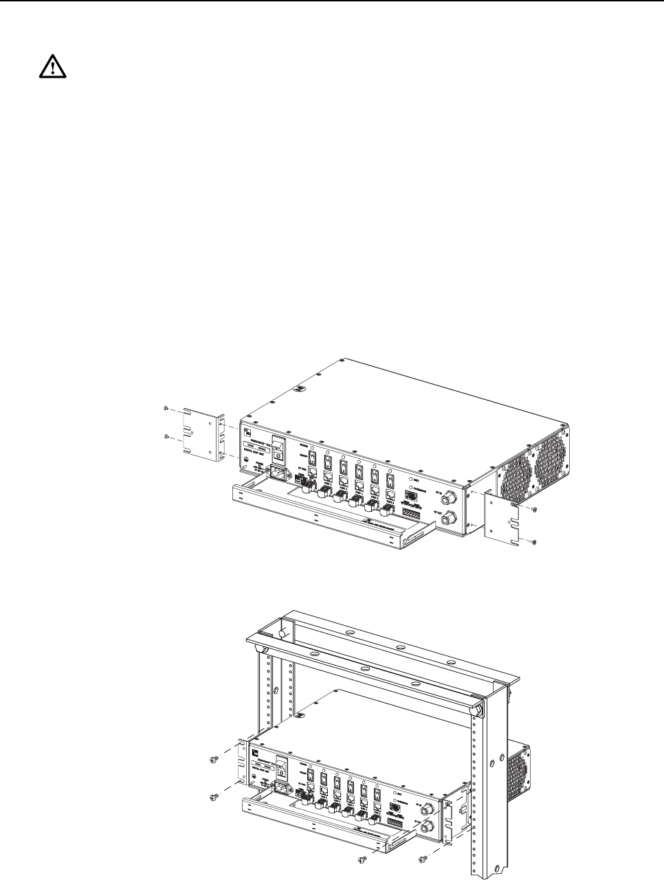
1. The DHU is shipped with the mounting brackets installed for 19-inch rack installations.
If mounting the DHU in a19-inch rack, proceed to step 4. If mounting the DHU in a 23-
inch rack, proceed to step 2.
2. Remove both mounting brackets from the DHU (requires TORX screwdriver with T20
bit)
3. Reinstall both mounting brackets so the long side of the bracket is flush with the DHU
front panel as shown in Figure 13. Use the screws removed in step 2to re-attach the
brackets to the DHU enclosure.
4. Position the DHU in the designated mounting space in the rack (per system design) as
shown in Figure 14.
17271-A
REMOVE AND REINSTALL MOUNTING
BRACKETS AS SHOWN FOR
INSTALLATION IN 23-INCH RACKS
Figure 13. Installing the Mounting Brackets for 23-Inch Rack Installations
17281-A
Figure 14. DHU Rack Mount Installation
ADCP-75-136 • Issue 1 • November 2002
Page 29
©2002, ADC Telecommunications, Inc.
5. Secure the mounting brackets to the rack using the four machine screws provided (use
#12-24 screws or M6 x10screws, whichever is appropriate).
Note:Provide aminimum of 3 inches (76 mm) of clearance space on both the left and
right sides of the DHU for air intake and exhaust.
4.4.2 Wall-Mount Installation
The DHU may be mounted from any flat vertical surface. It is recommended that abacker
board such as 3/4-inch plywood be applied over the mounting surface to provide asecure base
for attaching the DHU. Two mounting holes are provided in the cable management tray for
securing the DHU to the mounting surface. The fasteners must be provided by the installer.
Use the following procedure to wall-mount the DHU:
Warning:Wet conditions increase the potential for receiving an electrical shock when
installing or using electrically-powered equipment. To prevent electrical shock, never install
or use electrical equipment in awet location or during alightning storm.
1. Obtain the appropriate fasteners (lag bolts, screw anchors, etc.) for securing the DHU to
the mounting surface.
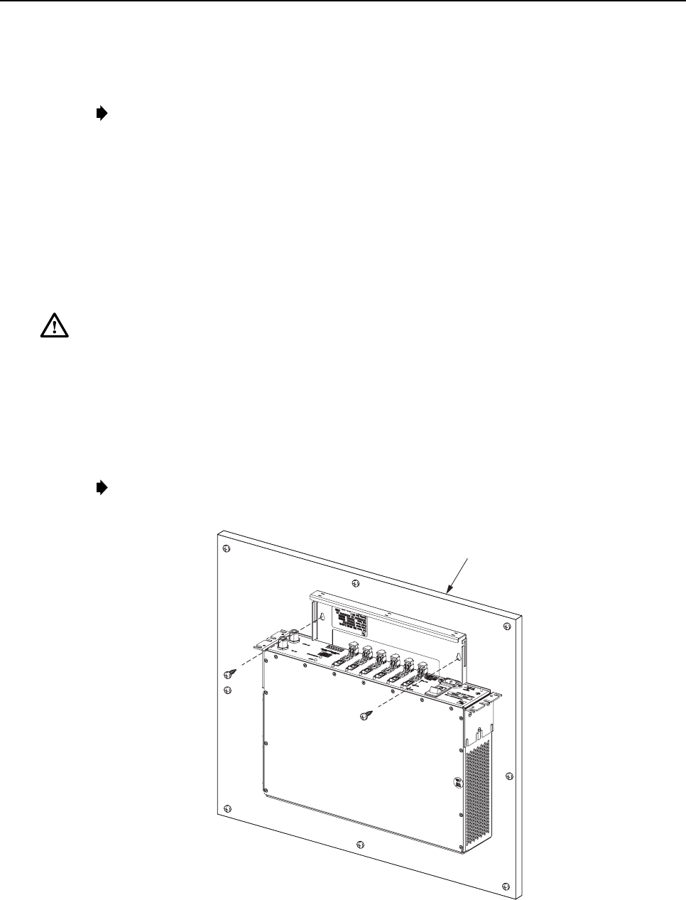
2. Position the DHU on the mounting surface in the specified location (per the system
design) with the front panel facing up as shown in Figure 15.
Note:Provide aminimum of 3 inches (76 mm) of clearance space on both the left and
right sides of the DHU for air intake and exhaust.
17272-A
BACKER BOARD SUCH
AS 3/4-INCH PLYWOOD
Figure 15. DHU Wall-Mount Installation
ADCP-75-136 • Issue 1 • November 2002
Page 30
©2002, ADC Telecommunications, Inc.
3. Using the DHU as atemplate, mark the location of the mounting holes on the mounting
surface.
Note:The mounting holes in the DHU cable management tray are spaced 11-21/32
inches (296 mm) center to center.
4. Set the DHU aside and then drill appropriately sized holes in the mounting surface for
the fasteners.
5. Partially install the fasteners in the drilled holes. Leave the head of each fastener
protruding about 1/4 inch (6 mm) from the mounting surface.
6. Hang the DHU from the fasteners and then securely tighten each fastener.
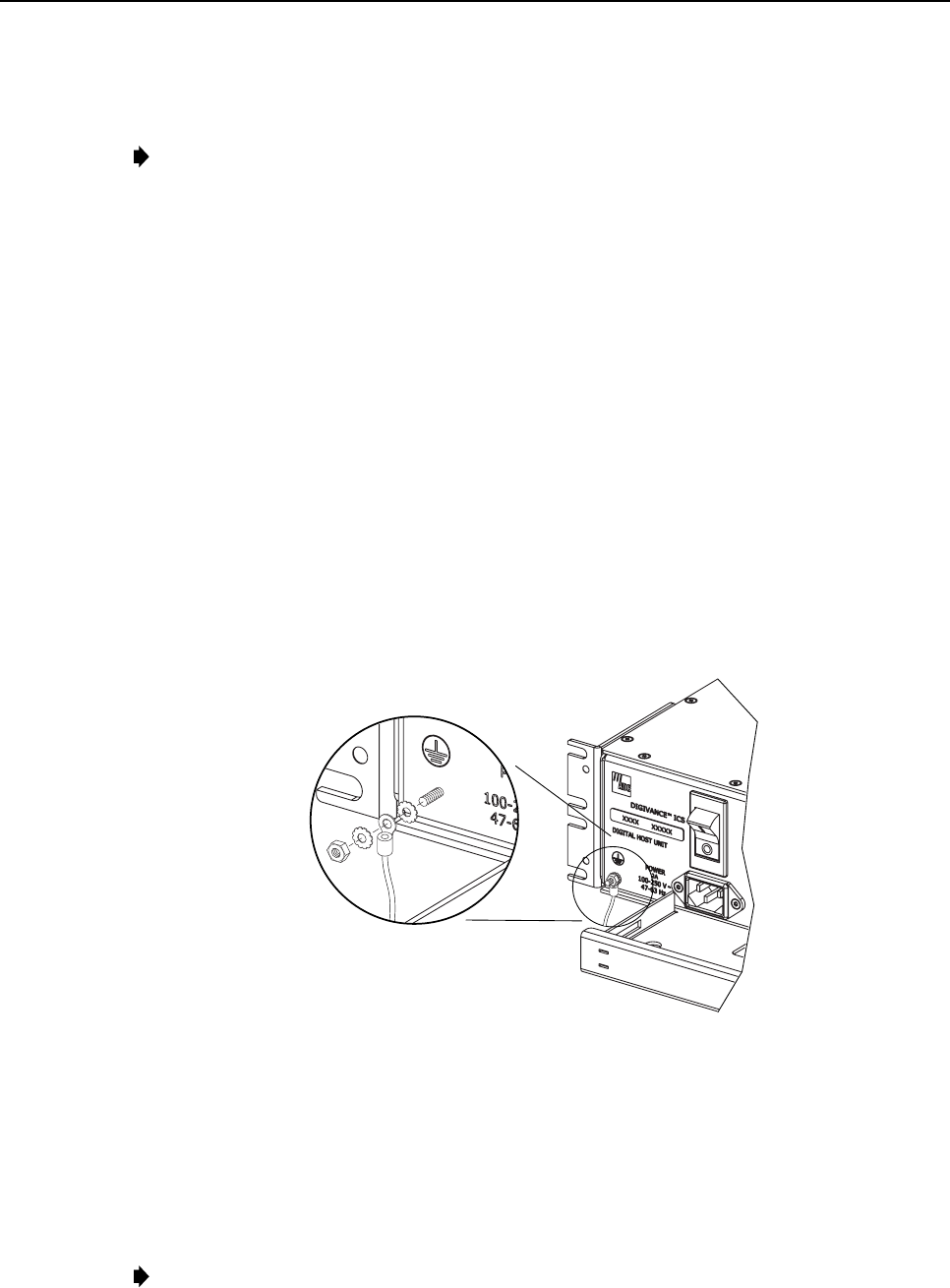
4.5 Chassis Ground Connections
Astud is provided on the front side of the chassis for connecting agrounding wire to the
chassis. Use the following procedure to connect the grounding wire to the chassis and to route
the grounding wire to an approved earth ground source:
1. Obtain alength of #18 AWG (1.00 mm) insulated stranded copper wire for use as a
chassis grounding wire.
2. Terminate one end of the wire with aring terminal.
3. Locate the chassis ground stud at the front of the DHU as shown in Figure 16.
17279-A
Figure 16. Chassis Ground Stud
4. Secure the ring end of the wire to the chassis ground stud (see Figure 16) using the nut
and two star washers provided.
5. Route the free end of the chassis grounding wire to an approved (per local code or
practice) earth ground source.
6. Cut the chassis grounding wire to length and connect it to the approved ground source as
required by local code or practice.
Note:Be sure to maintain reliable grounding for rack and wall mounted equipment. Pay
particular attention to ground source connections.
ADCP-75-136 • Issue 1 • November 2002
Page 31
©2002, ADC Telecommunications, Inc.
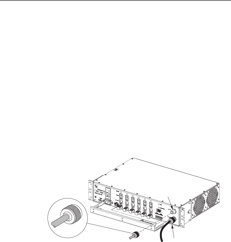
4.6 Coaxial Cable Connections
The RF interface between DHU and the BTS is supported through apair of type Nfemale
connectors mounted on the DHU front panel. One connector provides the coaxial cable
connection for the forward path (downlink) signal. The other connector provides the coaxial
cable connection for the reverse path (uplink) signal. Coaxial cables link the DHU to the BTS
through an interface device. Use the following procedure to install the forward and reverse
path coaxial cables and connect them to the DHU:
1. Obtain the required lengths of high performance, flexible, low loss 50-ohm coaxial
communications cable (RG 400 or equivalent) for all coaxial connections.
2. Route the forward path and reverse path coaxial cables (if not already routed) between
the DHU and the specified BTS interface device (per system design) and cut to the
required length. Allow sufficient slack for dressing and organizing cables at the DHU.
3. Terminate each cable with atype Nmale connector following the connector supplier’s
recommendations.
4. Connect the forward path cable to the RF IN connector on the DHU front panel as
shown in Figure 17.
5. Connect the reverse path cable to the RF OUT connector on the DHU front panel as
shown in Figure 17.
17273-A
TYPE-N MALE CONNECTOR
RF IN CONNECTOR
(FORWARD PATH)
RF OUT CONNECTOR
(REVERSE PATH)
Figure 17. Forward and Reverse Path Coaxial Cable Connections
6. Dress and secure cables at the DHU per standard industry practice.
7. Connect the forward and reverse path cables to the local (microcell) or remote (donor
antenna) interface device as specified in the instructions provided with that unit.
8. Complete all remaining coaxial cable connections between the local interface device and
the BTS or between the remote interface device and the donor antenna as specified in the
instructions provided with the equipment.
ADCP-75-136 • Issue 1 • November 2002
Page 32
©2002, ADC Telecommunications, Inc.
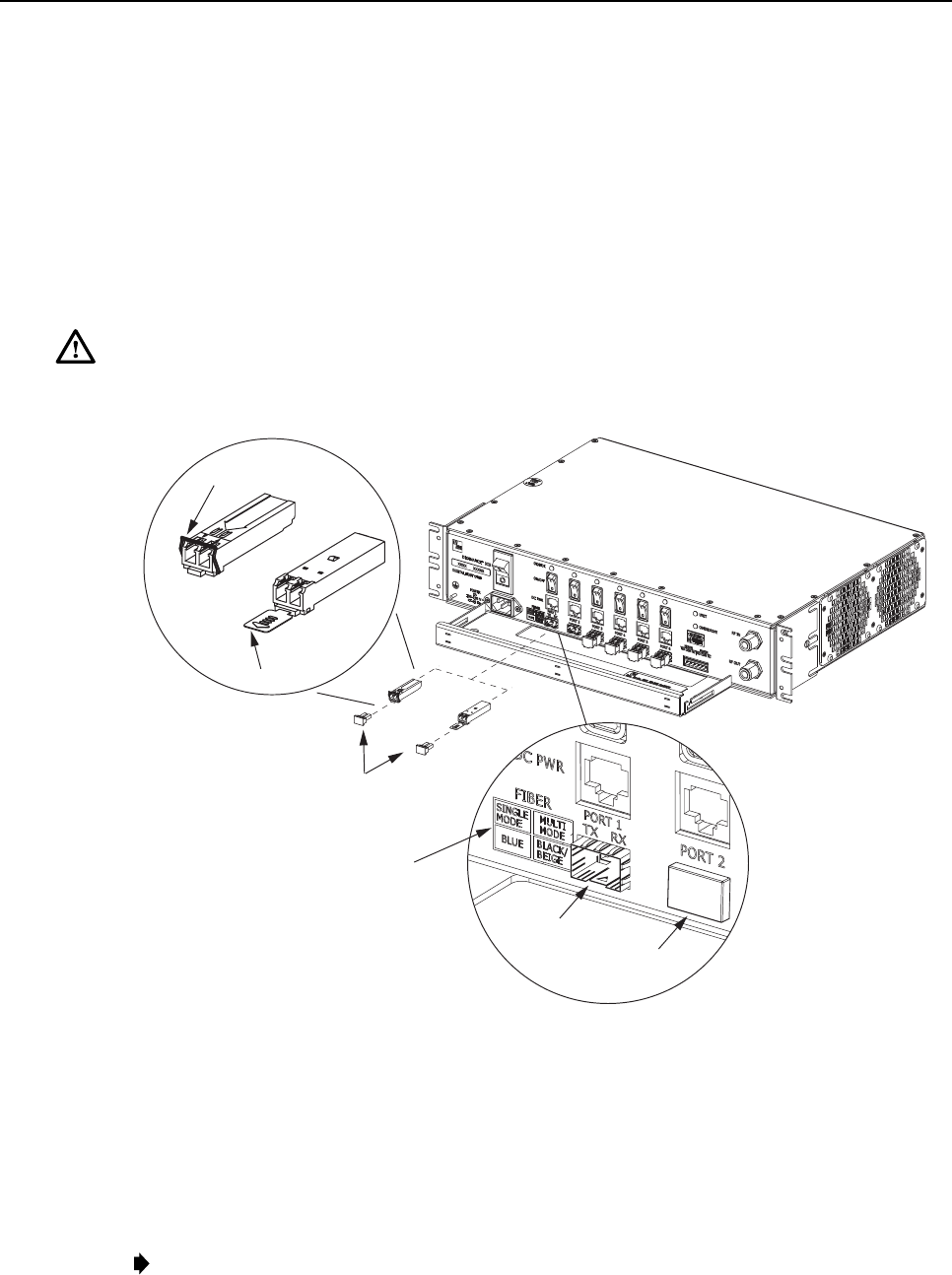
4.7 Modular Optical Transceiver Installation
The modular optical transceivers are available separately and may or may not be installed in
the DHU depending on the configuration ordered. If the optical transceivers are factory
installed in the DHU, skip this section and proceed to Section 4.8. If the optical transceivers
are not factory installed, use the following procedure to install each transceiver:
1. Slip on an Electro-Static Discharge (ESD) wrist strap and connect the ground wire to an
earth ground source such as the grounding stud on the DHU front panel. Wear the ESD
wrist strap while completing the optical transceiver installation procedure.
Warning:Electronic components can be damaged by static electrical discharge. To prevent
ESD damage, always wear an ESD wrist strap when handling electronic components.
2. Locate the appropriate transceiver socket on the front of the DHU as shown in Figure 18.
TXRX
DETAIL DRAWING OF
OPTICAL TRANSCEIVER
SOCKETS
DETAIL DRAWING
OF TYPE A AND TYPE B
MODULAR OPTICAL
TRANSCEIVERS
TX RX
TYPE A
TRANSCEIVER
TYPE B
TRANSCEIVER
RELEASE
LEVER
RELEASE TAB
OPTICAL
TRANSCEIVER
SOCKET
TRANSCEIVER COLOR CODE
BLUE = SINGLE-MODE (9 MICRON)
BLACK/
BEIGE = MULTI-MODE (50 OR 62.5 MICRON)
17258-A
PORT
COVER
DUST CAPS
Figure 18. Optical Transceiver Installation
3. Select the optical transceiver that corresponds to the type of fiber (single- or multi-mode)
required for the installation. The color of the transceiver (see transceiver color code in
Figure 18) corresponds to the fiber type.
4. Remove the transceiver from the anti-static packaging and orient for installation (see
Figure 18.).
Note:Two types of optical transceivers, type Aand type B, are available. Both types
provide the same functionality. On the type Aoptical transceiver, the release lever (see
Figure 18) must be closed for installation.