ADC Telecommunications DISSMRAA Digivance Indoor Coverage Solution System User Manual 75136 CV
ADC Telecommunications Inc Digivance Indoor Coverage Solution System 75136 CV
Contents
- 1. manual 1
- 2. manual 2
- 3. manual 3
- 4. manual 4
manual 3

ADCP-75-136 • Issue 1 • November 2002
Page 33
©2002, ADC Telecommunications, Inc.
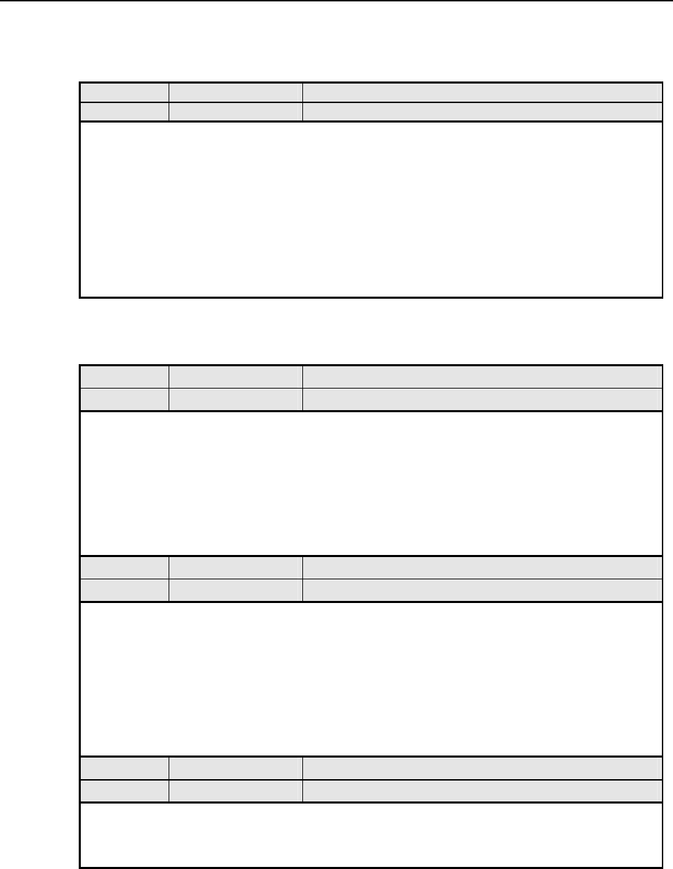
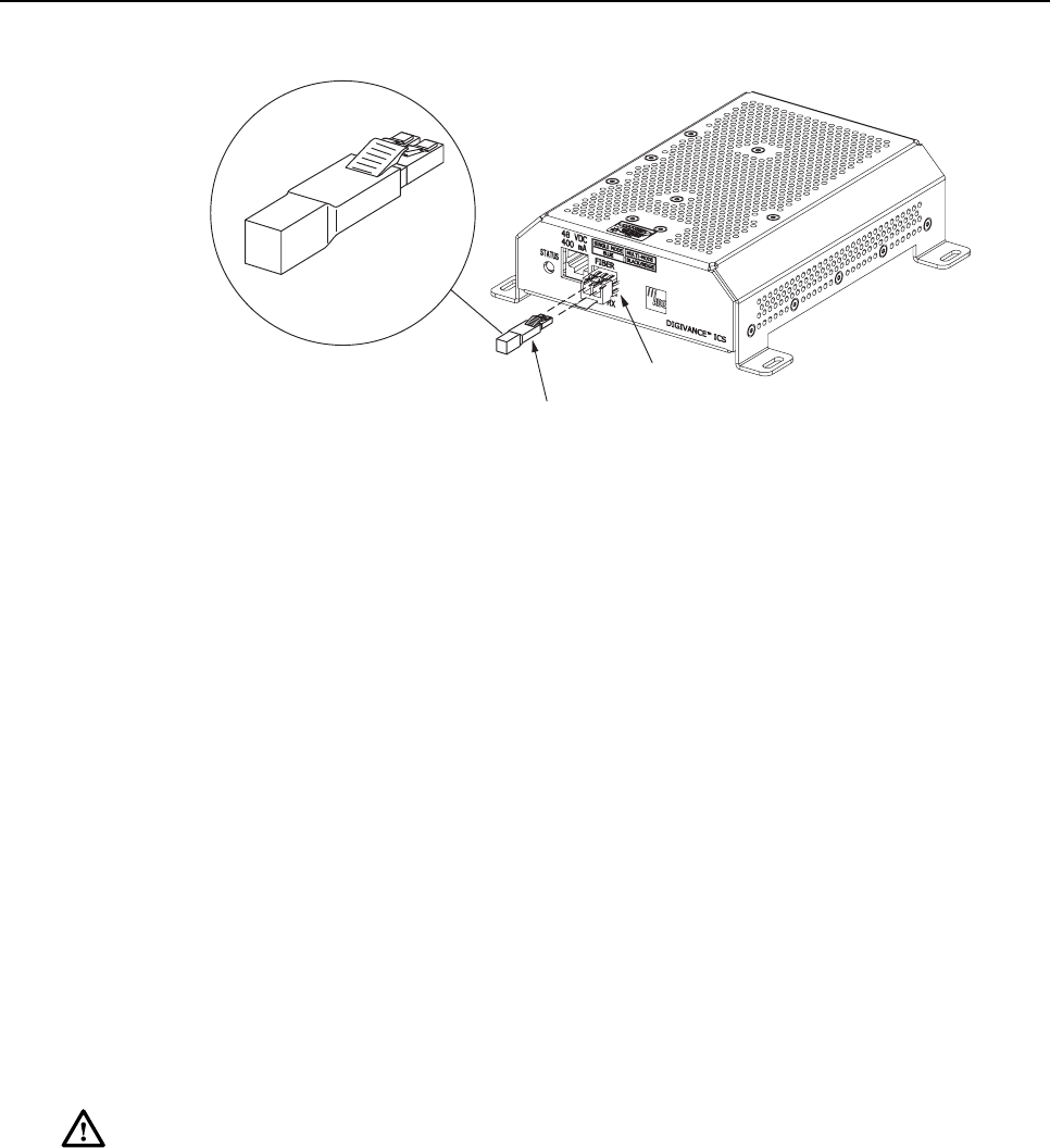
5. Insert the optical transceiver into the socket until it locks into place.
6. Replace the optical transceiver dust cap if it was removed for installation.
7. Repeat procedure for each optical transceiver that requires installation.
8. Install a port cover (see Figure 18) over each unused optical transceiver socket.
4.8 Ports 1–6 Optical Connections
The optical interface between the DHU and each DEU or DRU is supported by six optical
ports. Each of the six optical ports provides aduplex LC-type optical transceiver which is
mounted on the DHU front panel. One side of the transceiver provides the optical fiber
connection for the forward path (downlink) signal. The other side of the transceiver provides
the optical fiber connection for the reverse path (uplink) signal. Use the following procedure to
install the forward and reverse path optical fibers and to connect them to the DHU:
Danger:This equipment uses aClass 1Laser according to FDA/CDRH rules. Laser radiation
can seriously damage the retina of the eye. Do not look into the ends of any optical fiber. Do
not look directly into the optical transceiver of any digital unit or exposure to laser radiation
may result. An optical power meter should be used to verify active fibers. Aprotective cap or
hood MUST be immediately placed over any radiating transceiver or optical fiber connector
to avoid the potential of dangerous amounts of radiation exposure. This practice also prevents
dirt particles from entering the transceiver or connector.
1. Obtain the required lengths of single- or multi-mode fiber optic cable.
2. Route the fiber optic cable between the DHU and the DEU or DRU (if not already
routed) and cut to required length. Allow sufficient slack for dressing and organizing the
cables at each unit. Maintain aminimum bend radius of 2 inches (50 mm).
Note:The maximum path lengths for the optical fibers are as follows: 500 meters (1,641
feet) for 62.5 micron core multi-mode fiber, 750 meters (2,461 feet) for 50 micron core
multi-mode fiber, and 10 km (32,808 ft) for 9micron core single-mode fiber.
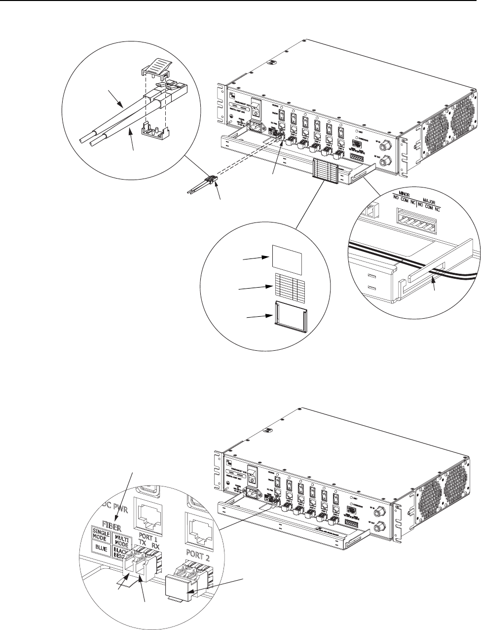
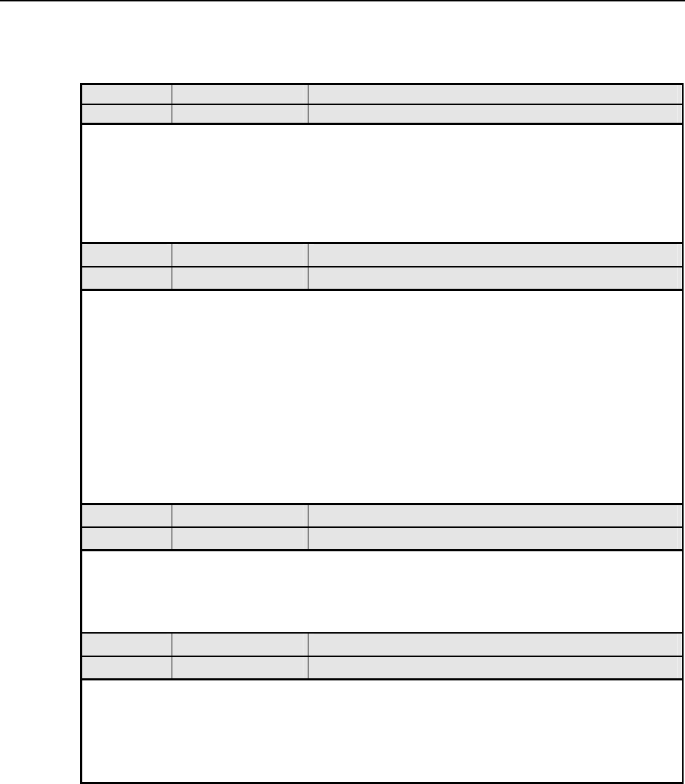
3. Terminate each optical fiber with afield-installable LC type fiber optic connector as
shown in Figure 19. Follow the instructions provided by the connector manufacturer for
installing the connector.
4. Test each fiber for optical loss as described in Subsection 6.4.2 of this manual.
5. Designate one of the fibers as the forward path fiber and the other as the reverse path
fiber and label both ends of each fiber with the path designation.
6. Use the plastic joiner provided with the LC connectors to join the DHU Port 1forward
and reverse path connectors together (see Figure 19). Make sure the forward path and
reverse path connectors are oriented as shown.
Note:When viewing any Port 1-6 optical transceiver from the front, the forward path port is
on the left and the reverse path port is on the right as shown in Figure 20. In addition, single-
mode transceivers are colored blue and multi-mode transceivers are colored black or beige.
Both single- and multi-mode transceivers may be mounted on the same DHU.
FCC ID: F8I-DISSMRAA, Partial User Manual, 3 of 4
ADCP-75-136 • Issue 1 • November 2002
Page 34
©2002, ADC Telecommunications, Inc.
17274-A
REVERSE PATH (RX)
CONNECTOR
FORWARD PATH (TX)
CONNECTOR
OPTICAL CONNECTOR
ASSEMBLY DETAIL
PORT 1
OPTICAL
TRANSCEIVER
OPTICAL
CONNECTOR
CABLE
GUIDES
CABLE GUIDE
DETAIL
DESIGNATION CARD AND
HOLDER DETAIL
HOLDER
CARD
CLEAR
PLASTIC
COVER
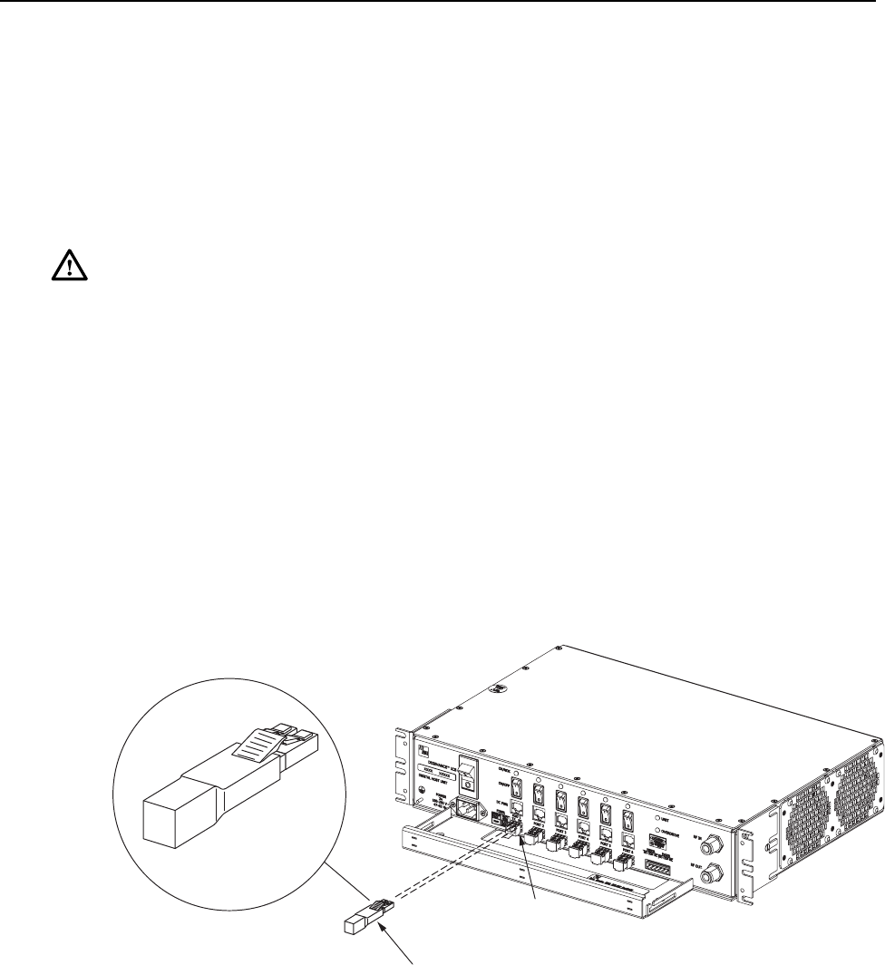
Figure 19. Ports 1–6 Fiber Optic Cable Connections
17150-A
DETAIL DRAWING OF
OPTICAL PORT
REVERSE
PATH (RX)
FORWARD
PATH (TX)
DUST CAP (LEAVE IN PLACE
UNTIL READY TO INSTALL CONNECTOR)
TRANSCEIVER COLOR CODE
BLUE = SINGLE-MODE (9 MICRON)
BLACK/
BEIGE = MULTI-MODE (50 OR 62.5 MICRON)
Figure 20. Optical Transceiver Designations
ADCP-75-136 • Issue 1 • November 2002
Page 35
©2002, ADC Telecommunications, Inc.
7. Remove the dust caps from the optical fiber connectors and the port 1optical transceiver.
Note:Leave the dust cap in place on any unused optical transceiver.
8. Clean each connector (follow connector supplier’s recommendations) and then insert the
optical fiber connector pair into DHU optical port 1 (see Figure 19).
9. Place the optical fibers within the cable guides provided on the cable management tray (see
Figure 19) and then dress and secure the fibers at the DHU per standard industry practice.
10. Connect the forward and reverse path optical fibers to the DEU or the DRU as specified
in the instructions provided with that unit.
11. Use the designation card provided (see Figure 19) to indicate the location and name of
the DRU or DEU that is connected to each optical fiber pair. The designation card holder
may be attached to any convenient flat surface such as the DHU cable management tray
12. Repeat steps 1–11 for each remaining optical port.
4.9 DC Power Connections
The DC power interface between the DHU and each DRU is supported by six RJ-45 female
connectors. Each DHU RJ-45 connector provides nominal 48 Vdc power for the associated
DRU except when the DRU is powered with an ac/dc converter. A category 3 or 5 twisted pair
cable is used to feed the power from the DHU to the DRU. Use the following procedure to
install the DC power cable and to connect it to the DHU.
1. Obtain the required length of category 3 or 5 twisted pair cable.
2. Route the cable between the DHU and the DRU (unless already routed) and then cut to
required length. Allow sufficient slack for dressing and organizing the cable at the DHU.
Note:The maximum distance for routing power cable is 500 meters (1,641 feet).
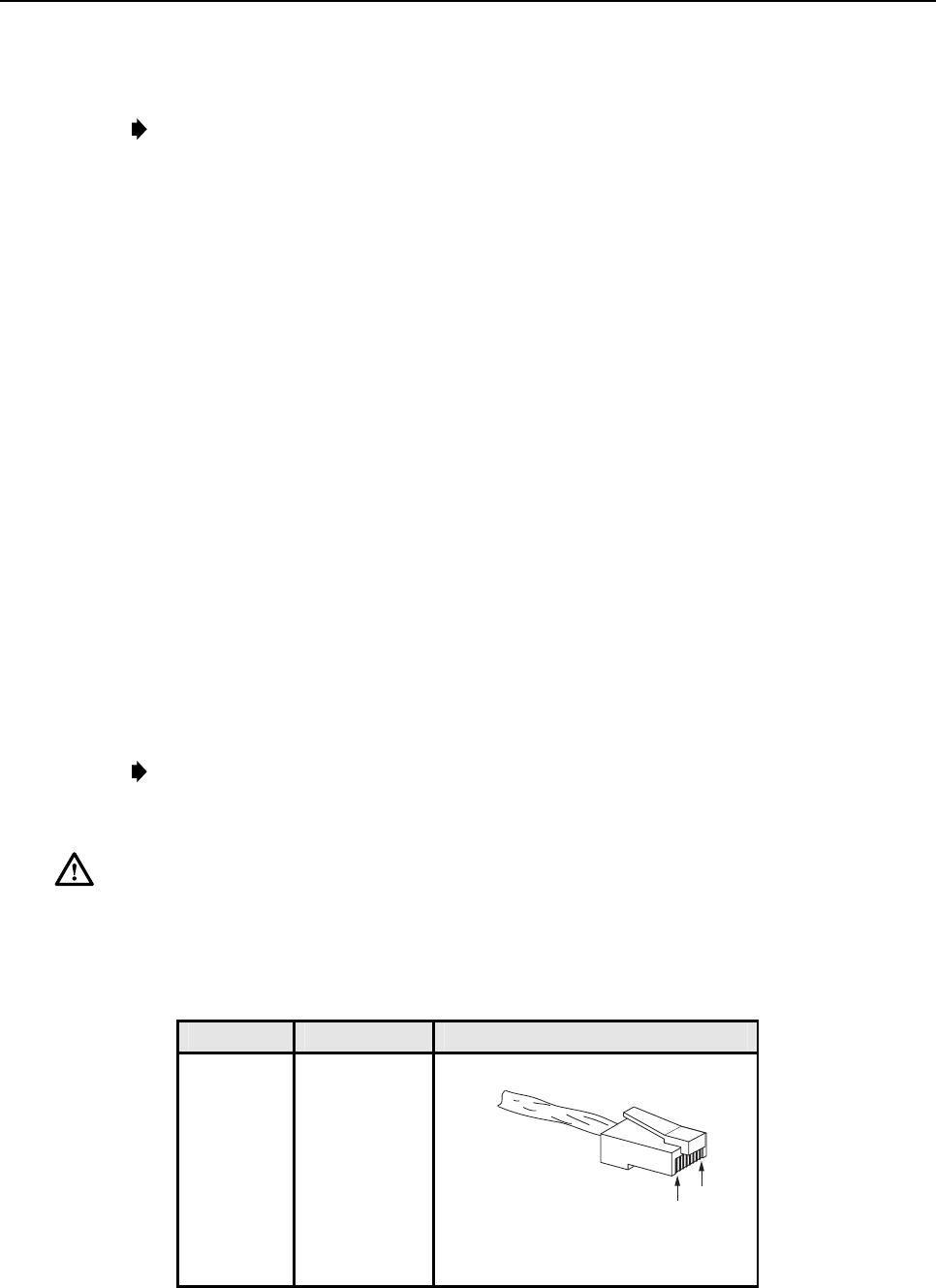
3. Terminate each end of the cable with amale RJ-45 connector. Match the wire color to
the connector pin as specified in Table 6.
Caution:The DRU will be damaged if the RJ-45 connector is wired incorrectly.
4. Perform acontinuity test to verify that each wire is properly connected to the terminating
RJ-45 connector and check the connector for correct polarity (see diagram in Table 6).
Table 6. RJ-45 Connector Pin Designations
PIN NUMBER WIRE COLOR CONNECTOR PINS
1
2
3
4
5
6
7
8
White/Green
Green
White/Orange
Orange
White/Blue
Blue
White/Brown
Brown
PIN
1
PIN
8
+48 VDC ON PINS 1, 3, 5, AND 7
RETURN ON PINS 2, 4, 6, AND 8
16180-A
ADCP-75-136 • Issue 1 • November 2002
Page 36
©2002, ADC Telecommunications, Inc.
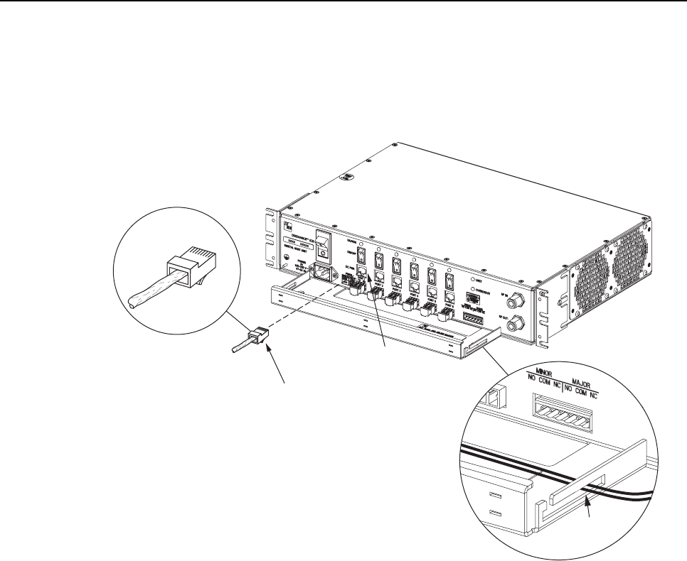
5. Connect the DC power cable to the DHU port 1 DC PWR jack as shown in Figure 21.
6. Place the DC power cable within the cable guides provided (see Figure 21) and then
dress and secure the cable at the DHU per standard industry practice.
17275-A
RJ-45 CONNECTOR
DETAIL
PORT 1
DC POWER
CONNECTOR
RJ-45
CONNECTOR
CABLE
GUIDES
CABLE GUIDE
DETAIL
1
8
Figure 21. 48 Vdc Power Cable Connection
7. Connect the DC power cable to the DRU as specified in the instructions provided with
that unit.
8. Repeat steps 1–7 for each remaining DRU that will be powered by the DHU.
4.10 External Alarm System Connections
The alarm interface between the DHU and an external alarm system is supported by a six-
terminal plug (with screw-type terminals) that connects to areceptacle mounted on the DHU
front panel. The terminal plug provides connections to normally open (NO) and normally
closed (NC) dry type alarm contacts for both minor and major alarms. Acategory 3 or 5 cable
is typically used to connect the DHU to the external alarm system. Use the following
procedure to install the alarm wiring and connect it to the DHU:
1. Obtain the required length of category 3 or 5 cable.
2. Route the cable between the DHU and the external alarm system (if not already routed)
and then cut to required length. Allow sufficient slack for dressing and organizing the
cable at the DHU.
ADCP-75-136 • Issue 1 • November 2002
Page 37
©2002, ADC Telecommunications, Inc.
3. Strip back the outer cable sheath and insulation to expose the wires at both ends of the
cable and strip back 0.2 inches (5 mm) of insulation each wire.
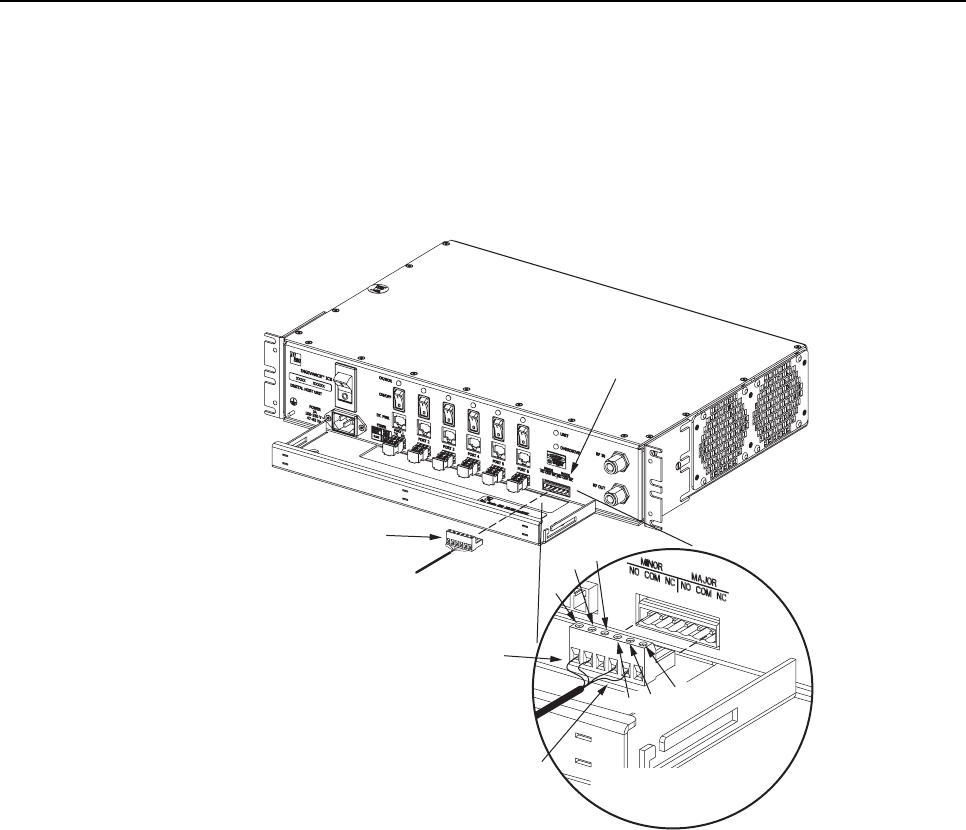
4. Connect the Major alarm wire pair to the MAJOR COM/NC or MAJOR COM/NO
terminals (whichever is required by the external alarm system) on the DHU alarm
terminal connector (supplied with DHU) as shown in Figure 22.
17278-A
ALARM
CONNECTOR
RECEPTACLE
MAJOR
ALARM
WIRES
MINOR
ALARM
WIRES
ALARM CONNECTOR
DETAIL
ALARM
CONNECTOR
NO
COM NC
MINOR
NO COM
NC
MAJOR
Figure 22. External Alarm System Connections
5. Connect the Minor alarm wire pair to the MINOR COM/NC or MINOR COM/NO
terminals (whichever is required by the external alarm system) on the DHU alarm
terminal connector as shown in Figure 22.
6. Insert the alarm terminal connector into the receptacle on the DHU front panel.
7. Connect the Major and Minor alarm wire pairs to the appropriate terminals on the
external alarm system.
8. Dress and secure cable per standard industry practice.
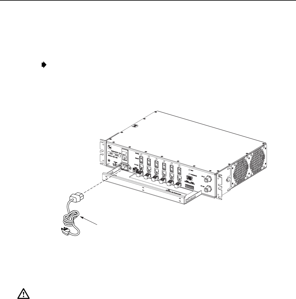
4.11 AC Power Connections
The AC power interface between the DHU and the AC power source is supported by a 3-wire
AC power cord connector located on the DHU front panel. The AC connector provides a
connection point for the power cord which is provided separately with the DHU. Use the
following procedure to install the AC power cord:
ADCP-75-136 • Issue 1 • November 2002
Page 38
©2002, ADC Telecommunications, Inc.
1. Locate the AC power cord which is provided separately with the DHU. Use only the AC
power cord provided with the DHU or an equivalent UL/CUL listed 3-conductor, 18
AWG cord terminated in amolded-on plug cap rated 125 V, 15 A with amaximum
length of 6 feet (1.8 m).
Note:The DHU is intended to be used with a 3-wire grounding type plug which has a
grounding pin. Equipment grounding is required to ensure safe operation. Do not defeat
the grounding means. Verify DHU is reliably grounded when installed.
2. Place the DHU AC power ON/OFF switch, shown in Figure 23, in the OFF position
(press O).
17276-A
AC POWER CORD
Figure 23. AC Power Connection
3. Connect the receptacle end of the power cord to the AC connector on the DHU.
4. Route the plug end of the power cord to the specified AC outlet (per the system design)
and connect plug to outlet.
Warning:The current rating of the DHU is 2.0 Amps at 120 Vac.Avoid overloading circuits
which may cause damage to over-current protection devices and supply wiring.
5. Dress and secure cable per standard industry practice.
6. When all units of the Digivance ICS have been installed, refer to Section 4 of this
manual for the system power up and test procedures.
4.12 Create As-Built Drawing
Following installation, create an “as-built” drawing of the complete Digivance ICS system.
Using adrawing of the building floor plan, show the installed location of each piece of
equipment including the various Digivance electronic units, the antennas, the interface units,
and the microcell (if used). In addition, show the location and routing of all copper, coaxial,
and fiber optic cable runs used with the system. Retain the as-built drawing for reference when
troubleshooting or when planning for system expansion.

ADCP-75-136 • Issue 1 • November 2002
Page 39
©2002, ADC Telecommunications, Inc.
5 SYSTEM OPERATION
This section provides guidelines for turning-up the Digivance ICS, verifying that all units are
operating properly, testing to ensure that all performance requirements are satisfied, and
correcting any installation problems. This process assumes that the various units that comprise
the Digivance ICS have been installed in accordance with the system design plan and the BTS
interface device has been installed and tested.
5.1 Tools and Materials
The following tools and materials are required in order to complete the procedures in this
section:
• Portable spectrum analyzer
• Portable test transmitter
• Cell phone
• Pencil or pen
• Writing pad
5.2 Turn-Up System and Verify Operation
The process of turning-up the system and verifying operation involves powering up the
various system components and then verifying that the LED indicators show normal operation.
Refer to Tables 7, 8, and 9as needed for acomplete description of the unit LED indicators.
Use the following procedure to power-up the system. If any unit does not respond as
described, refer to Subsection 5.3 for the correction procedures.
1. Temporarily disconnect the alarm system or notify alarm system provider that testing is
in progress.
2. Verify that each AC powered unit is connected to the appropriate outlet.
3. Place the ON/OFF switch on the DHU in the ON position (press I).
4. Verify that the UNIT LED and the OVERDRIVE LED on the DHU turn yellow (for
approximately 6seconds) and then green.
5. Place the PORT 1ON/OFF switch on the DHU in the ON position (press I).
6. If aDEU is connected to port 1, proceed to step 7. If aDRU is connected to port 1, skip
steps 7and 8and proceed to step 9.
7. Place the ON/OFF switch on the DEU in the ON position (press I).
8. Verify that the UNIT LED on the DEU turns yellow (for approximately 6seconds) and
then green.
9. Verify that the PORT 1OK/NOK LED on the DHU turns yellow (for approximately 6
seconds) and then green.
10. If aDEU is connected to PORT 1, proceed to step 11. If aDRU is connected to PORT 1,
skip steps 11 through 13 and proceed to step 14.

ADCP-75-136 • Issue 1 • November 2002
Page 40
©2002, ADC Telecommunications, Inc.
11. Verify that the HOST PORT LED on the DEU turns green.
12. Place the PORT 1ON/OFF switch on the DEU in the ON position (press I).
13. Verify that the PORT 1OK/NOK LED on the DEU turns yellow (for approximately six
seconds) and then green.
14. Verify that the STATUS LED on the DRU connected to PORT 1turns yellow (for
approximately six seconds) and then green.
15. Repeat the procedure covered in steps 5through 14 for each of the remaining DHU
optical ports (ports 2through 6) that is connected to aDEU or a DRU.
16. Reconnect the alarm system and notify alarm system provider that system is operational.
Table 7. Digital Host Unit LED Indicators
INDICATOR COLOR DESCRIPTION
UNIT
LED Green
Yellow
Red
Off
Indicates when the DHU is normal or faulty.
DHU in normal state, no faults detected.
DHU high temperature fault detected. (see Note)
DHU fault detected (see Note).
AC power off to DHU or DHU internal fault.
PORT 1–6
OK/NOK
LEDs Green
Yellow
Red
(steady)
Red
(blinking)
Off
Indicates if any connected DEU or DRU is normal or faulty or if the
optical inputs from any connected DEU or DRU are normal or lost.
All connected units in normal state, no faults detected.
High temperature fault detected in connected DEU. (see Note)
Fault detected in aconnected DEU or DRU. (see Note)
No reverse path optical signal detected from aconnected DEU or DRU or
excessive reverse path errors detected from aconnected DEU or DRU.
(see Note)
Port disabled (via front panel switch) or DHU internal fault.
OVERDRIVE
LED
Green
Red
Indicates when the forward path RF input is below or above the
overdrive threshold.
RF input signal level at DHU below overdrive threshold.
RF input signal level at DHU above overdrive threshold.
Note:Detection of any fault will generate an alarm. A high temperature fault will generate aminor
alarm (yellow LED). All other types of faults will generate amajor alarm (red LED).

ADCP-75-136 • Issue 1 • November 2002
Page 41
©2002, ADC Telecommunications, Inc.
Table 8. Digital Expansion Unit LED Indicators
INDICATOR COLOR DESCRIPTION
UNIT
LED Green
Yellow
Red
Off
Indicates when the DEU is normal or faulty.
DEU in normal state, no faults detected.
DEU high temperature fault detected. (see Note)
DEU internal fault detected. (see Note)
AC power off to DEU or DEU internal fault.
HOST PORT
LED
Green
Red
(blinking)
Off
Indicates when the optical inputs from the DHU or supporting
DEU are normal or lost.
DHU or supporting DEU in normal state, no faults detected.
No forward path optical signal detected from DHU or supporting DEU
or excessive forward path errors detected from DHU or supporting
DEU. (see Note).
DEU internal fault.
PORT 1–6
OK/NOK
LEDs Green
Yellow
Red
(steady)
Red
(blinking)
Off
Indicates if any connected DEU or DRU is normal or faulty or if the
optical inputs from any connected DEU or DRU are normal or lost.
DRU or remote DEU in normal state, no faults detected.
High temperature fault detected in connected DEU. (see Note)
Fault detected in aconnected DEU or DRU. (see Note)
No reverse path optical signal detected from aconnected DEU or DRU
or excessive reverse path errors detected from aconnected DEU or
DRU.
Port disabled (via front panel switch) or DEU internal fault.
Note:Detection of any fault will generate an alarm. A high temperature fault will generate aminor
alarm (yellow LED). All other types of faults will generate amajor alarm (red LED).
Table 9. Digital Remote Unit LED Indicator
INDICATOR COLOR DESCRIPTION
STATUS
LED
Green
Red
(steady)
Red
(blinking)
Off
Indicates if the DRU is normal or faulty or if the forward path optical
inputs to the DRU are normal or lost.
DRU in normal state, no faults detected.
DRU internal fault detected. (See Note)
No forward path optical signal from the DHU or DEU detected.
DC power off to DRU or DRU internal fault.
Note:Detection of any fault will generate an alarm. A high temperature fault will generate
aminor alarm (yellow LED). All other types of faults will generate amajor alarm (red LED).

ADCP-75-136 • Issue 1 • November 2002
Page 42
©2002, ADC Telecommunications, Inc.
5.3 Test System Performance
Testing the performance of the system involves completing various RF tests and telephone
service tests that verify if the system is functioning properly. Use the following procedure to
test the system performance:
1. Verify that the forward path (downlink) input signal level at the DHU is optimized. The peak
COMPOSITE forward path input signal level at the DHU should be set at –20 dBm.
Note:In aCDMA system, the power level is dependent on the traffic. For optimum
operation in aCDMA system, the input signal level should be set below the level of the
pilot signal.
2. Verify that the reverse path (uplink) signal level at the local BTS or donor antenna is
optimized. Note that the reverse path output signal level required is dependent on service
provider signal to noise requirements, ICS system noise floor, the service provider
equipment, and the system configuration.
3. Check and record the Received Signal Strength Indication (RSSI) and any spurious
emission levels at and between all DRU antennas. Analyze all DRU’s and the DHU
interface using aspectrum analyzer.
4. Plot the RSSI levels on a floor plan of the building and check against the pre-installation
RSSI levels to determine the overall and average RSSI improvement attributed to the
Digivance ICS. Check the entire Digivance coverage area.
5. Verify call processing and voice quality within the coverage areas. Initiate and receive
multiple long and short duration calls. Document the performance and address any issues
as calls are processed within the entire coverage area. Assuming a properly functioning
server RF link and BTS and a properly designed and optimized ICS system, there should
be no clicks, mutes, clipping, or crackles within the coverage area. In awireless office
application, hand off will not occur.
6. If the DHU interfaces with alocal BTS (microcell), verify the handoff function by
placing acall and confirming handoffs between the Digivance/microcell coverage area
and the outdoor macrocell coverage area (macro system) and vice versa. The handoff
should take place without any noticeable call quality or performance issues.
7. If the DHU interfaces with aremote BTS through a donor antenna, verify call quality by
placing acall and then walking between the Digivance coverage area and an area
receiving good coverage directly from the cell site base station. There should be no
noticeable difference in call quality.
8. Following service provider guidelines, test the 411 and 911 links to verify the routing of
emergency and special services calls on local BTS configurations.
9. Verify that the alarm reporting system functions properly by turning the DHU off. This
should generate amajor and minor alarm and operate both the major and minor alarm
contacts. Check for alarm confirmation from the service provider’s local switch and
Network Operations Center (NOC). Note that this tests only the external alarm system
and does not verify operation of the Digivance alarm reporting system.

ADCP-75-136 • Issue 1 • November 2002
Page 43
©2002, ADC Telecommunications, Inc.
6 SYSTEM MAINTENANCE PROCEDURES
This section explains the alarm reporting system, provides amethod for isolating and
troubleshooting faults, and provides procedures for replacing the modular transceivers and the
DHU or DEU cooling fans.
The Digivance ICS requires no regular maintenance to insure continuous and satisfactory
operation. Maintenance, as it applies to the Digivance ICS, primarily involves diagnosing and
correcting service problems as they occur. When an alarm is reported, it will be necessary to
follow asystematic troubleshooting procedure to locate the problem. Once the source of the
problem is isolated, the appropriate corrective action can be taken to restore service. The only
unit components that can be replaced are the cooling fans that mount in the DHU and DEU
and the modular optical transceivers. The failure of any other component within aunit will
require replacement of that unit.
6.1 Tools and Materials
The following tools and materials are required in order to complete the procedures in this
section:
• ESD wrist strap
• IR filtering safety glasses
• Optical loopback device (such as Stratos Lightwave LC5 series) and LC duplex adapter
• Optical power meter
• Magnification device for inspecting LC connectors
• Laser light source
• Multimeter
• Cell phone
• RJ-45 circuit access tool (such as the Harris 8-wire Banjo Adapter)
• Medium and small size flat-bladed screwdrivers
• TORX screwdriver (T10)
6.2 Fault Detection and Alarm Reporting
Detection of a fault by the Digivance ICS will generate an external alarm response. LED
indicators are provided on the front panel of the various units to indicate when afault is
detected. In addition to LED indicators, the DHU also provides normally open (NO) and
normally closed (NC) dry alarm contacts for reporting minor and major alarms to an external
alarm system. Aminor alarm is defined as ahigh temperature condition. Amajor alarm is
defined as any fault condition except high temperature.
When the DHU alarm contacts are connected to an external alarm system, detection of a fault
will generate an alarm at the Network Operations Center (NOC). However, various types of
faults may not generate an alarm response. In this case, the first indication of a problem will
probably be from cell phone users reporting aloss of service or poor service. Whenever a
problem is reported, whether by a external alarm system or by a call from auser, refer to
Subsection 6.3 to isolate and correct the fault.
ADCP-75-136 • Issue 1 • November 2002
Page 44
©2002, ADC Telecommunications, Inc.
6.3 Fault Isolation and Troubleshooting
Fault isolation and troubleshooting guidelines are provided in Tables 11, 12, 13, and 14. When an
alarm is reported, determine the type of alarm generated (minor or major) and then check the LED
indicators on the DHU and note any that are red, yellow, or off.If any of the Port 1–6 OK/NOK
LED indicators on the DHU are red or yellow, also check the LED indicators on the connected
DEU’s and/or DRU’s and note if any are red or yellow. Start the troubleshooting process at the
DHU and then work toward the unit where the alarm originated. The troubleshooting tables are
organized according to unit type. Locate the problem in the appropriate table, check out the
suggested possible causes, and take corrective action as required.
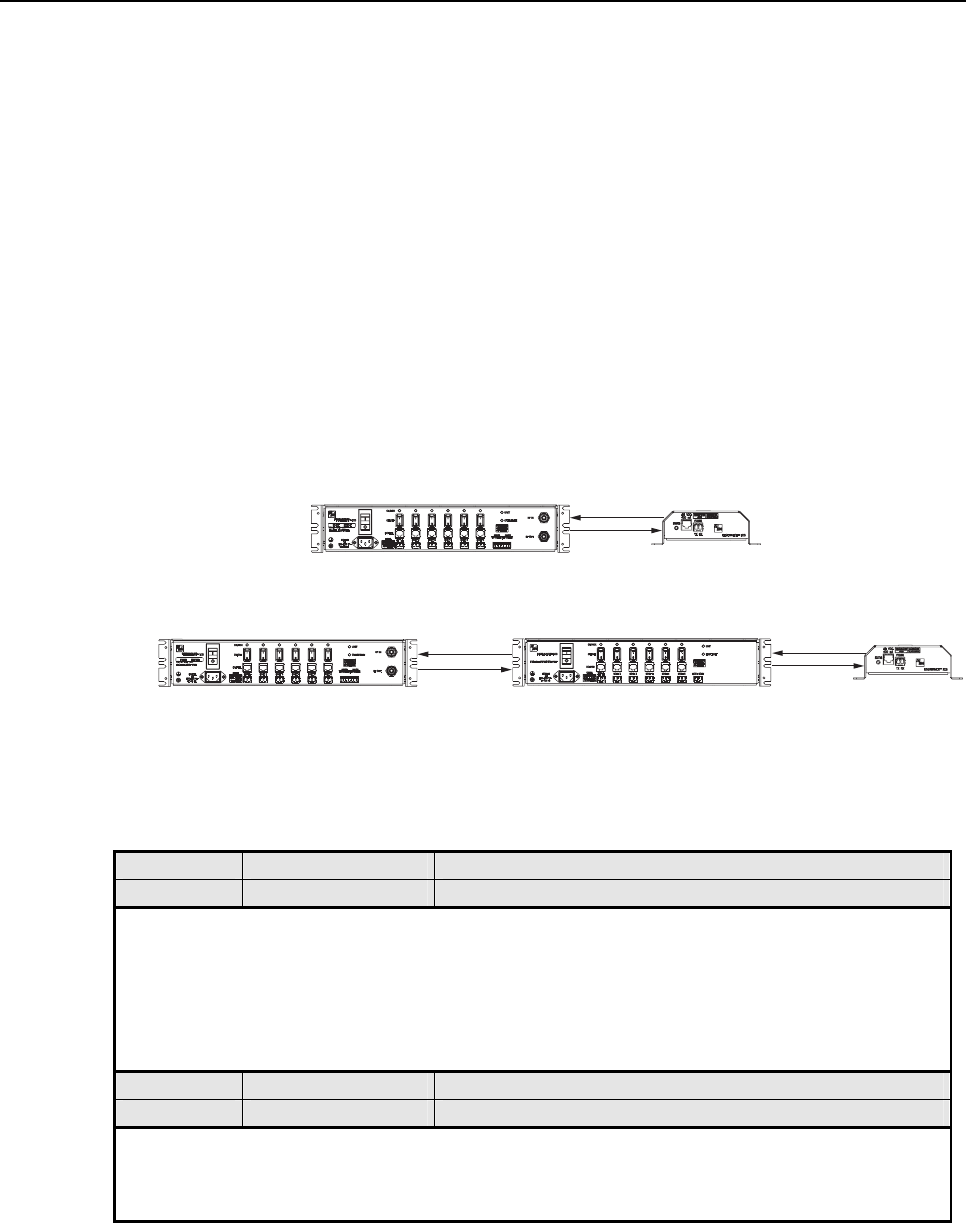
Figure 24 shows two basic ICS system configurations. The troubleshooting tables list possible
causes for various problems. If the cause of aparticular problem is specific to either of the two
system configurations shown in Figure 24, the type of system configuration (1 or 2) will be
referenced in the table.
17962-A
FWD
REV
DRU
FWD
REV
DRU
FWD
REV
DIGITAL EXPANSION UNITDIGITAL HOST UNIT
DIGITAL HOST UNIT
(2)
(1)
Figure 24. ICS System Basic Configurations
Table 11. DHU Fault Isolation and Troubleshooting Guidelines
Alarm Type LED LED COLOR
Minor UNIT Yellow
Problem : The DHU is overheating.
POSSIBLE CAUSE CORRECTIVE ACTION/COMMENTS
1. Air intake or exhaust openings to DHU
chassis blocked.
2. Ambient temperature > 50º C/122º F.
3. Faulty fan.
1. Remove cause of air-flow blockage.
2. Reduce ambient temperature.
3. Replace fan (see Subsection 6.5).
Alarm Type LED LED COLOR
Major UNIT Red
Problem : The DHU detects an internal circuitry fault.
POSSIBLE CAUSE CORRECTIVE ACTION/COMMENTS
1. Faulty DHU. 1. Replace DHU.
(Continued)
ADCP-75-136 • Issue 1 • November 2002
Page 45
©2002, ADC Telecommunications, Inc.
Table 11. DHU Fault Isolation and Troubleshooting Guidelines (Continued)
Alarm Type LED LED COLOR
Major OVERDRIVE Red
Problem: Forward path RF input level too high.
POSSIBLE CAUSE CORRECTIVE ACTION/COMMENTS
1. Incorrect attenuation in forward path RF
coaxial link. 1. Adjust attenuation at interface device.
Alarm Type LED LED COLOR
Minor OK/NOK Yellow
Problem: The DHU is receiving a minor alarm signal from the DEU.
POSSIBLE CAUSE CORRECTIVE ACTION/COMMENTS
1. The connected DEU is overheating (2). 1. Check DEU UNIT indicator and then refer to the
appropriate troubleshooting section for procedures.
Alarm Type LED LED COLOR
Major OK/NOK Blinking Red
Problem: The DHU is not receiving an optical signal from the DRU or DEU.
POSSIBLE CAUSE CORRECTIVE ACTION/COMMENTS
1. Forward and reverse path optical fibers
reversed between DHU and DRU (1); or
between DHU and DEU (2).
2. Faulty reverse path optical fiber between DHU
and DRU (1).
3. Faulty optical receive port at DHU or faulty
optical transmit port at DRU (1).
4. Faulty forward or reverse path optical fiber
between DHU and DEU (2).
1. Check fiber connections for correct polarity and
reverse connectors at either unit if mismatched.
2. Clean optical connector and then test optical fiber.
Repair or replace if faulty (see Subsection 6.4.2).
3. Make sure transceiver is fully plugged in and then
test optical port. Replace optical transceiver if
port is faulty (see Subsection 6.4.1).
4. Clean optical connectors and then test optical
fibers. Repair or replace if faulty (see Subsection
6.4.2).
Alarm Type LED LED COLOR
Major OK/NOK Red
Problem: The DHU is receiving a major alarm signal from the DRU.
POSSIBLE CAUSE CORRECTIVE ACTION/COMMENTS
1. Faulty forward path optical fiber between
DHU and DRU (1).
2. Faulty optical transmit port at DHU or faulty
optical receive port at DRU (1).
3. The DRU is faulty (1 and 2).
4. Faulty forward or reverse path optical fiber
between the DEU and DRU (2).
1. Clean optical connector and then test optical fiber.
Repair or replace if faulty (see Subsection 6.4.2).
2. Make sure transceiver is fully plugged in and then
test optical port. Replace optical transceiver if
port is faulty (see Subsection 6.4.1).
3. Check DEU UNIT indicator or DRU STATUS
indicator and then refer to appropriate trouble-
shooting section for procedures.
4. Check the status of the OK/NOK LED on the
DEU and then Refer to Table 12.
ADCP-75-136 • Issue 1 • November 2002
Page 46
©2002, ADC Telecommunications, Inc.
Table 12. DEU Fault Isolation and Troubleshooting Guidelines
Alarm Type LED LED COLOR
Minor UNIT Yellow
Problem : The DEU is overheating.
POSSIBLE CAUSE CORRECTIVE ACTION/COMMENTS
1. Air intake or exhaust openings to DEU
chassis blocked.
2. Ambient temperature > 50º C/122º F.
3. Faulty fan.
1. Remove cause of air-flow blockage.
2. Reduce ambient temperature.
3. Replace fan (see Subsection 6.5).
Alarm Type LED LED COLOR
Major UNIT Red
Problem : The DEU detects an internal circuitry fault.
POSSIBLE CAUSE CORRECTIVE ACTION/COMMENTS
1. Faulty DEU. 1. Replace DEU.
Alarm Type LED LED COLOR
Major HOST PORT Blinking Red
Problem: The DEU is not receiving an optical signal from the DHU.
POSSIBLE CAUSE CORRECTIVE ACTION/COMMENTS
1. Faulty forward path optical fiber between DEU
and DHU (2).
2. Faulty optical receive port at DEU or faulty
optical transmit port at DHU (2).
1. Clean optical connector and then test optical fiber.
Repair or replace if faulty (see Subsection 6.4.2).
2. Make sure transceiver is fully plugged it and then
test optical port. Replace optical transceiver if
port is faulty (see Subsection 6.4.1).
Alarm Type LED LED COLOR
Minor OK/NOK Yellow
Problem: The DEU is receiving a minor alarm signal from a connected DEU.
POSSIBLE CAUSE CORRECTIVE ACTION/COMMENTS
1. The connected DEU is overheating. 1. Check DEU UNIT indicator and then refer to the
appropriate troubleshooting section for procedures.
Alarm Type LED LED COLOR
Major OK/NOK Blinking Red
Problem: The DEU is not receiving an optical signal from the DRU.
POSSIBLE CAUSE CORRECTIVE ACTION/COMMENTS
1. Forward and reverse path optical fibers
reversed between DEU and DRU.
2. Faulty reverse path optical fiber between DEU
and DRU.
3. Faulty optical receive port at DEU or faulty
optical transmit port at DRU.
1. Check fiber connections for correct polarity and
reverse connectors at either unit if mismatched.
2. Clean optical connector and then test optical fiber.
Repair or replace if faulty (see Subsection 6.4.2).
3. Make sure transceiver is fully plugged in and then
test optical port. Replace optical transceiver if
port is faulty (see Subsection 6.4.1).
(Continued)
ADCP-75-136 • Issue 1 • November 2002
Page 47
©2002, ADC Telecommunications, Inc.
Table 12. DEU Fault Isolation and Troubleshooting Guidelines (Continued)
Alarm Type LED LED COLOR
Major OK/NOK Red
Problem: The DEU is receiving a major alarm signal from the connected DRU.
POSSIBLE CAUSE CORRECTIVE ACTION/COMMENTS
1. Faulty forward path optical fiber between DEU
and DRU.
2. Faulty optical transmit port at DEU or faulty
optical receive port at DRU.
3. The connected DRU is faulty.
1. Clean optical connector and then test optical fiber.
Repair or replace if faulty (see Subsection 6.4.2).
2. Make sure transceiver is fully plugged in and then
test optical port. Replace optical transceiver if
port is faulty (see Subsection 6.4.1).
3. Check DRU STATUS indicator and then refer
to appropriate troubleshooting section for
procedures.
Table 13. DRU Fault Isolation and Troubleshooting Guidelines
Alarm Type LED LED COLOR
Major STATUS Off
Problem : The DRU is not powered.
POSSIBLE CAUSE CORRECTIVE ACTION/COMMENTS
1. DC power cable open.
2. No power or insufficient power output from
ac/dc power converter, DHU (1), or DEU (2).
3. Faulty DRU.
1. Test cable for continuity and repair or replace if
faulty.
2. Check DC voltage level at the DRU (see Subsection
6.4.3). Replace converter, DHU, or DEU (whichever
applies) if voltage is not within 34 to 48 Vdc.
3. Replace DRU.
Alarm Type LED LED COLOR
Major STATUS Blinking Red
Problem : The DRU is not receiving an optical signal from the DHU or DEU; or the DHU or DEU is not receiving
an optical signal from the DRU.
POSSIBLE CAUSE CORRECTIVE ACTION/COMMENTS
1. Faulty forward or reverse path optical fiber
between DHU and DRU (1), DEU and
DRU (2), or DEU and DHU (2).
2. Faulty optical transmit or receive port at the
DHU (1) or DEU (2); or faulty optical
transmit or receive port at DRU (1 and 2).
1. Clean optical connector and then test optical fiber.
Repair or replace if faulty (see Subsection 6.4.2).
2. Make sure transceiver is fully plugged it and then
test optical port. Replace optical transceiver if
port is faulty (see Subsection 6.4.1).
Alarm Type LED LED COLOR
Major STATUS Red
Problem: The DRU detects an internal circuitry fault.
POSSIBLE CAUSE CORRECTIVE ACTION/COMMENTS
1. Faulty DRU. 1. Replace DRU.
ADCP-75-136 • Issue 1 • November 2002
Page 48
©2002, ADC Telecommunications, Inc.
Table 14. System Fault Isolation and Troubleshooting Guidelines
Alarm Type LED LED COLOR
None All Normal
Problem: Loss of phone service from one DRU. Service normal at all other DRU’s.
POSSIBLE CAUSE CORRECTIVE ACTION/COMMENTS
1. DRU antenna cable disconnected.
2. DRU antenna obstructed or misdirected.
3. DRU antenna faulty.
4. DRU faulty.
1. Re-connect DRU antenna cable to DRU.
2. Remove antenna obstruction or re-orient antenna.
3. Replace antenna.
4. Replace DRU.
Alarm Type LED LED COLOR
None All Normal
Problem: Loss of phone service from all DRU’s.
POSSIBLE CAUSE CORRECTIVE ACTION/COMMENTS
1. Faulty coaxial connection between DHU
and the interface device.
2. Faulty coaxial connection between interface
device and the BTS or donor antenna.
3. Faulty interface equipment.
4. Faulty DHU
5. Fault with cellular network or equipment.
1. Check forward path signals at the DHU. Check
reverse path signals at the interface device.
2. Check forward path signals at the interface
equipment. Check reverse path signals at the BTS or
antenna.
3. Adjust or replace interface equipment.
4. Replace DHU.
5. Contact cell service provider and verify that
cellular network and equipment is operational.
Alarm Type LED LED COLOR
None All Normal
Problem: Calls may be originated and terminated but service is noisy.
POSSIBLE CAUSE CORRECTIVE ACTION/COMMENTS
1. Some electrical device in the immediate
vicinity is creating interference. 1. Try turning off each device that may be causing
interference and see if problem corrects itself.
Alarm Type LED LED COLOR
None All Normal
Problem: Sudden high rate of blocked calls (delay dial tone).
POSSIBLE CAUSE CORRECTIVE ACTION/COMMENTS
1. Too many users for the number of channels
available.
2. Faulty DHU, DEU, or DRU.
1. Wait afew minutes and try dialing again. Upgrade
service if additional channels are required.
2. Replace defective unit.
ADCP-75-136 • Issue 1 • November 2002
Page 49
©2002, ADC Telecommunications, Inc.
6.4 Test Procedures
6.4.1 Optical Loopback Test Procedure
Dirty optical connectors, afaulty optical transceiver, abreak in an optical fiber, or a fault in an
optical connector will interrupt communications between fiber-linked components. Use the
following procedure to determine if afault exists with an optical port or with an optical fiber:
Danger:This equipment uses aClass 1Laser according to FDA/CDRH rules. Laser radiation
can seriously damage the retina of the eye. Do not look into the ends of any optical fiber. Do
not look directly into the optical transceiver of any digital unit or exposure to laser radiation
may result. An optical power meter should be used to verify active fibers. Aprotective cap or
hood MUST be immediately placed over any radiating transceiver or optical fiber connector
to avoid the potential of dangerous amounts of radiation exposure. This practice also prevents
dirt particles from entering the transceiver or connector.
1. Put on the IR filtering safety glasses.
2. At the DHU or supporting DEU, place the PORT ON/OFF switch for the fiber port or
fiber to be tested in the OFF position (press O).
3. Disconnect the optical connectors for the fiber port to be tested and place adust cap over
each connector.
4. Plug aloopback into the optical port to be tested as shown in Figure 25.
17277-A
OPTICAL LOOPBACK
CONNECTION DETAIL
PORT 1
OPTICAL
TRANSCEIVER
OPTICAL
LOOPBACK
Figure 25. DHU/DEU Loopback Test
5. At the DHU or supporting DEU, place the PORT ON/OFF switch in the ON position
(press I).
ADCP-75-136 • Issue 1 • November 2002
Page 50
©2002, ADC Telecommunications, Inc.
6. The PORT OK/NOK LED will turn either blinking red or green. If the LED turns
blinking red, the optical port is faulty. Replace the optical transceiver and then recheck
system operation. If the LED turns green, the optical port is good. Proceed to step 7to
continue the test procedure.
7. Place the PORT ON/OFF switch in the OFF position (press O).
8. Disconnect the loopback from the DHU or supporting DEU.
9. Clean and then reconnect the optical fiber connectors to the DHU or DEU optical port.
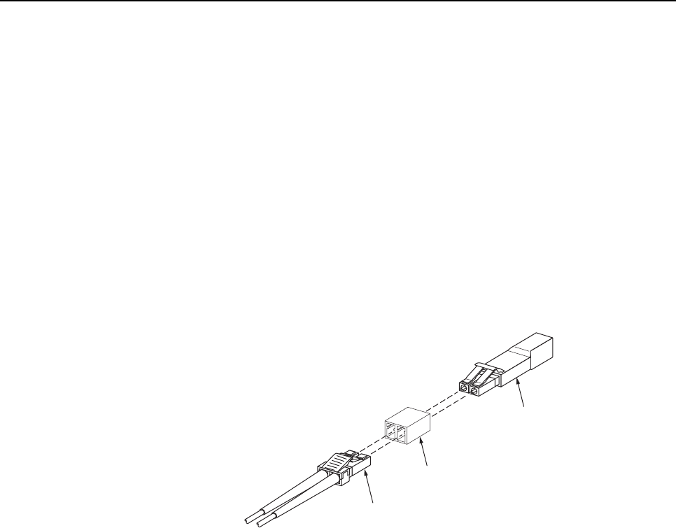
10. Disconnect the optical connectors at the DRU optical port or remote DEU host port (far
end of fiber).
11. Clean the optical fiber connectors and then using an LC optical adapter, connect the
loopback to the connectors as shown in Figure 26.
16768-B
OPTICAL
ADAPTER
OPTICAL
LOOPBACK
OPTICAL
CONNECTOR
NOTE: iF THE DISTANCE BETWEEN THE DHU/DEU AND THE
DRU EXCEEDS THE DISTANCE SHOWN BELOW, THE
REMOTE LOOPBACK TEST WILL NOT WORK.
62.5 MICRON MULTI-MODE FIBER - 250 METERS
50 MICRON MULTI-MODE FIBER - 375 METERS
9 MICRON SINGLE-MODE FIBER - 5 KILOMETERS
Figure 26. Optical Fiber Loopback Test
12. Insert adust plug into the DRU optical port or remote DEU host port.
13. At the DHU or supporting DEU, place the PORT ON/OFF switch in the ON position
(press I).
14. The PORT OK/NOK LED will turn either blinking red or green. If the LED turns
blinking red, one of the optical fibers is faulty. Refer to Subsection 6.4.2 to isolate which
fiber is at fault. If the LED turns green, the optical fibers are good. Proceed to step 14 to
finish the test procedure.
15. At the DHU or supporting DEU, place the PORT ON/OFF switch in the OFF position
(press O).
16. Disconnect the loopback and the optical adapters from the optical fiber connectors.
17. Place adust cap over the connector for each optical fiber
18. Remove the dust plug from the DRU optical port or remote DEU host port.
19. Plug the loopback into the DRU optical port or DEU host port as shown in Figure 27.
20. If testing aDRU that is powered by the DHU or by a supporting DEU, place the PORT
ON/OFF switch in the ON position (press I).
ADCP-75-136 • Issue 1 • November 2002
Page 51
©2002, ADC Telecommunications, Inc.
17282-A
OPTICAL LOOPBACK
CONNECTION DETAIL
OPTICAL
TRANSCEIVER
OPTICAL
LOOPBACK
Figure 27. DRU Loopback Test
21. The DRU STATUS LED or DEU HOST LED will turn either blinking red or green. If
the LED turns blinking red, the optical port is faulty and the optical transceiver must be
replaced. If the LED turns green, the optical port is good.
22. At the DHU or supporting DEU, place the PORT ON/OFF switch in the OFF position
(press O).
23. Remove the loopback from the DRU optical port or remote DEU host port.
24. Clean the optical fiber connectors and then reconnect the optical fibers to the DRU
optical port or remote DEU host port.
25. At the DHU or supporting DEU, place the PORT ON/OFF switch in the ON position
(press I).
26. Verify that the PORT OK/NOK LED turns green.
6.4.2 Optical Loss Test Procedure
Abreak in an optical fiber or a fault with the optical connector will interrupt communications
between linked components. Use the following procedure to isolate aproblem with an optical
fiber or optical connector:
Danger:This equipment uses aClass 1Laser according to FDA/CDRH rules. Laser radiation
can seriously damage the retina of the eye. Do not look into the ends of any optical fiber. Do
not look directly into the optical transceiver of any digital unit or exposure to laser radiation
may result. An optical power meter should be used to verify active fibers. Aprotective cap or
hood MUST be immediately placed over any radiating transceiver or optical fiber connector
to avoid the potential of dangerous amounts of radiation exposure. This practice also prevents
dirt particles from entering the transceiver or connector.
1. Put on the IR filtering safety glasses.
2. At the DHU or supporting DEU, place the PORT ON/OFF switch for the optical fiber to
be tested in the OFF position (press O)if not already off.
ADCP-75-136 • Issue 1 • November 2002
Page 52
©2002, ADC Telecommunications, Inc.
3. Disconnect the optical connectors at the DHU or supporting DEU and at the
corresponding DRU or remote DEU.
4. Inspect the optical connectors. Verify that each connector is clean and that no scratches
or imperfections are visible on the fiber end. Clean and polish the optical connector if
necessary.
5. Connect a laser light source to one end of the first optical fiber and an optical power
meter to the other end.
6. Verify that the power loss is within specifications (8 dB loss) for the length of the fiber
installed. If the power loss is not within specifications, repair or replace the optical fiber
and/or connector per local practice.
7. Repeat steps 5and 6for the second optical fiber.
8. Reconnect the optical connectors at the DHU or supporting DEU and the corresponding
DRU or remote DEU.
9. At the DHU or supporting DEU, place the PORT ON/OFF switch for the fiber that was
tested in the ON position (press I).
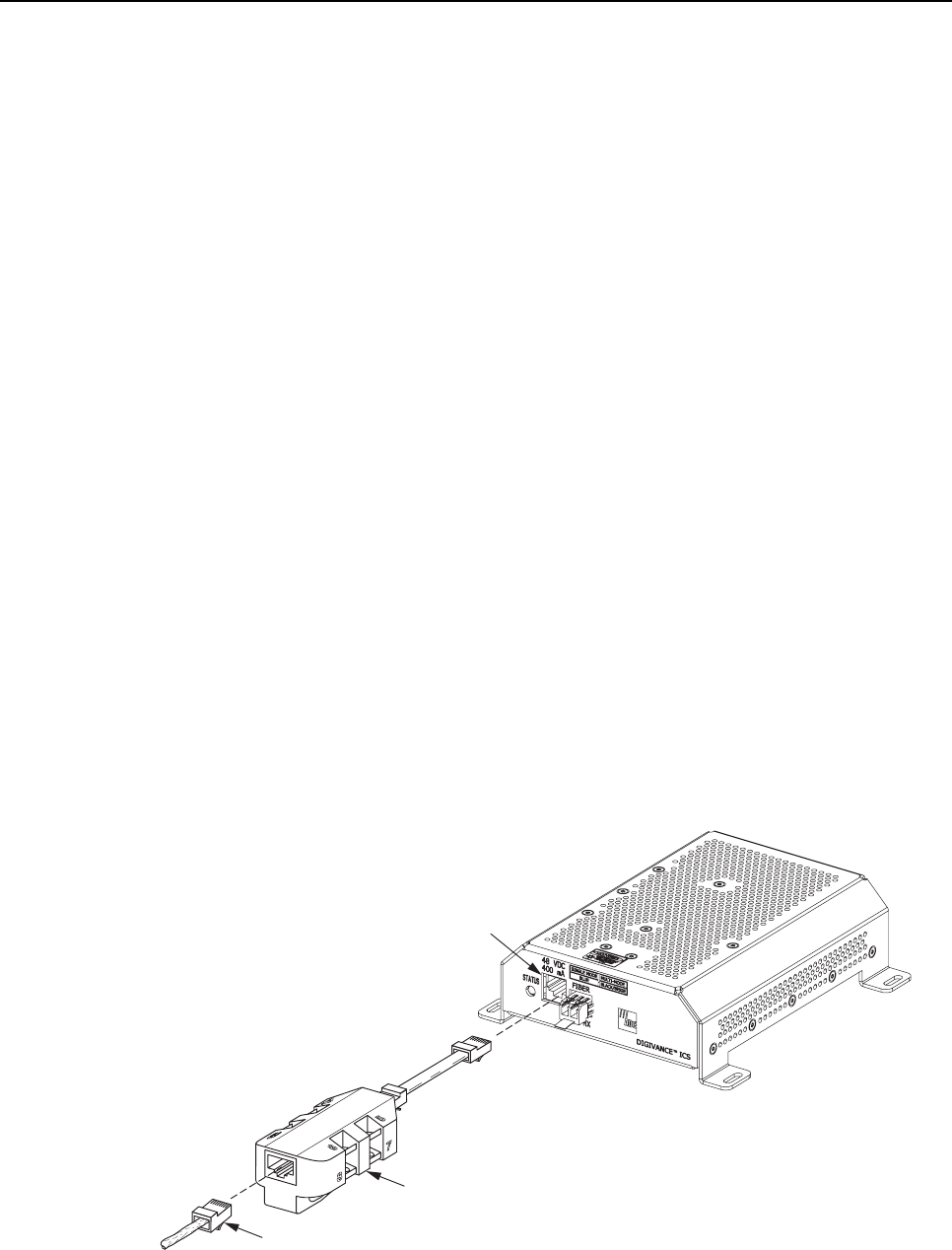
6.4.3 DC Power Test Procedure
The DRU is powered by 34–48 Vdc power which is supplied through the RJ-45 connector.
Power to the DRU may be supplied by the DHU, DEU, or by a 120 Vac to 48 Vdc power
converter (available separately as an accessory item) plugged into a properly grounded 120
Vac outlet. Use the following procedure to test the DC power cable:
1. Disconnect the DC power cable from the DRU.
2. Connect the RJ-45 circuit access tool to the DRU as shown in Figure 28.
POWER
PORT
POWER
CONNECTOR
RJ-45 CIRCUIT
ACCESS TOOL
17284-A
Figure 28. Connect RJ-45 Circuit Access Tool