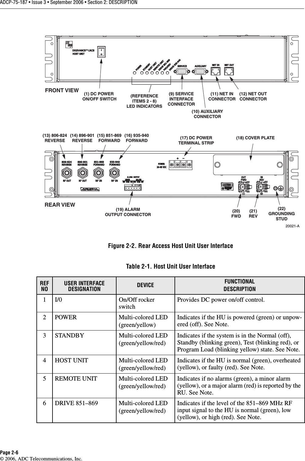
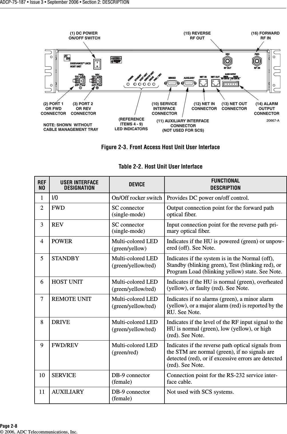
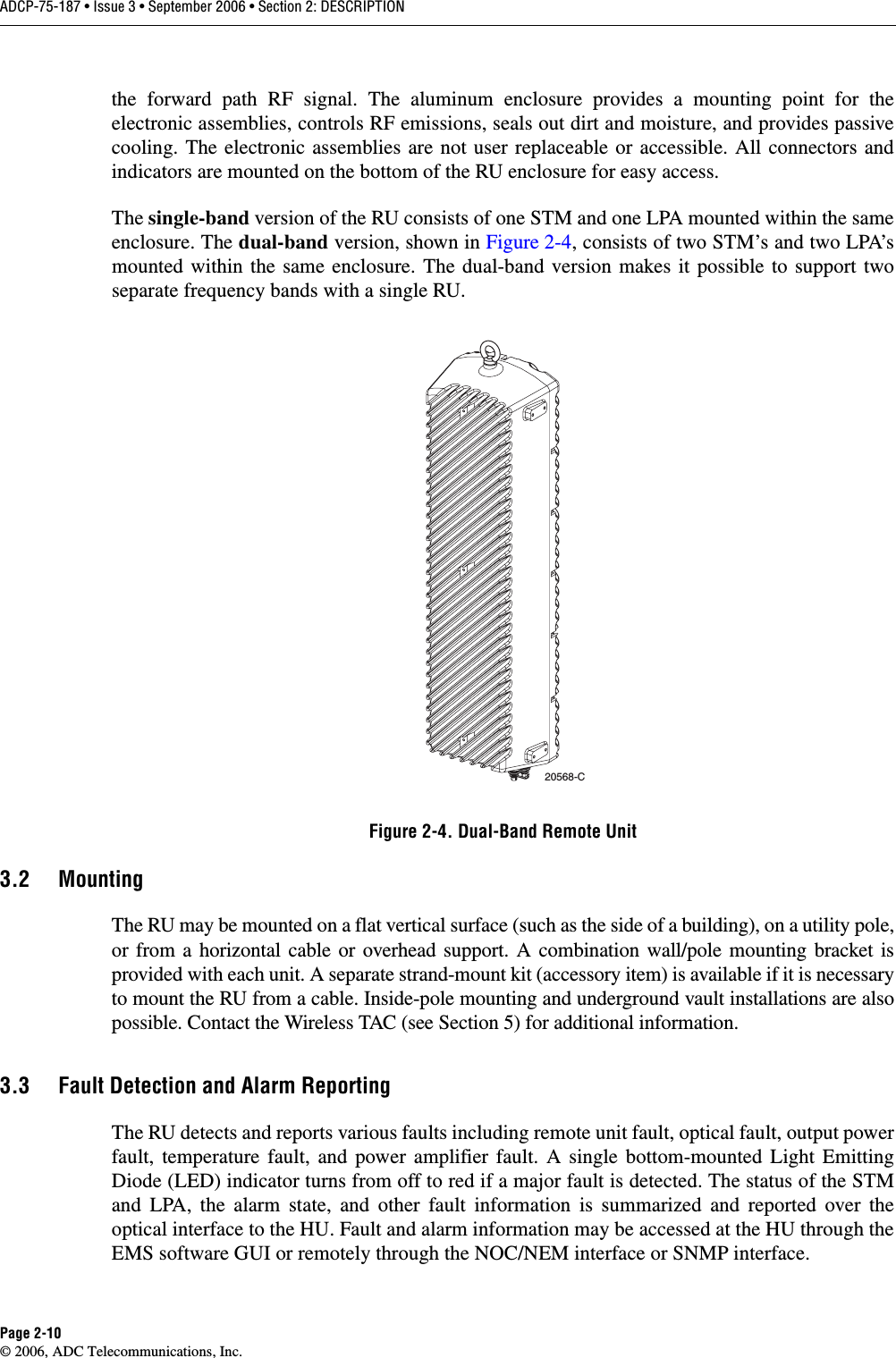
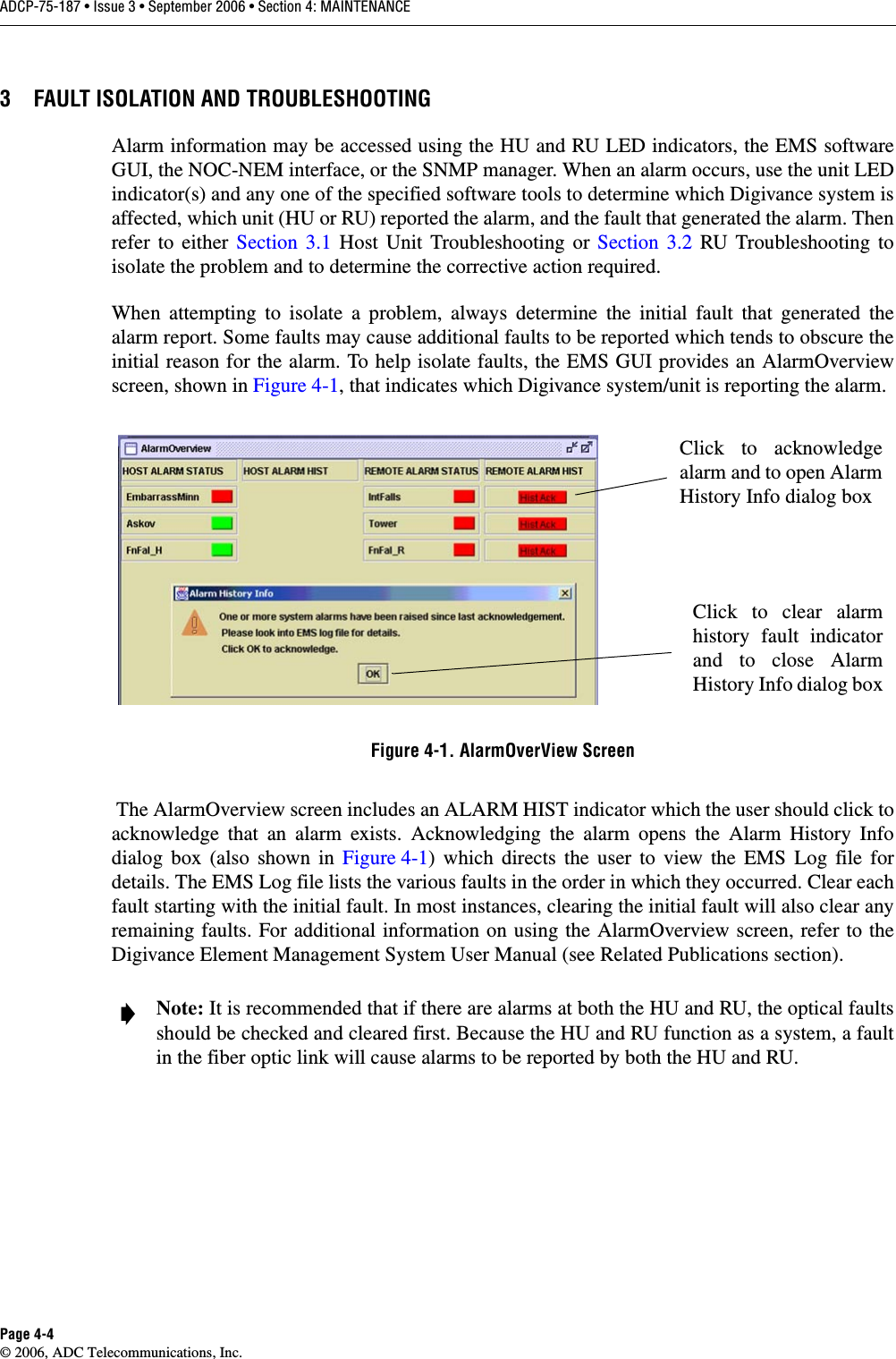
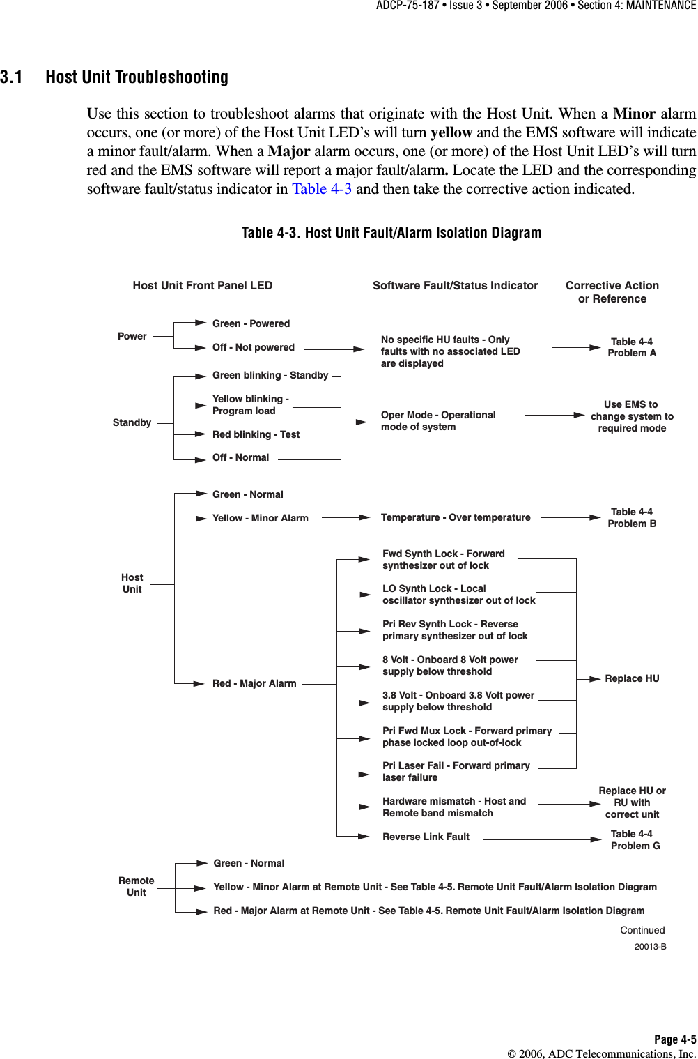
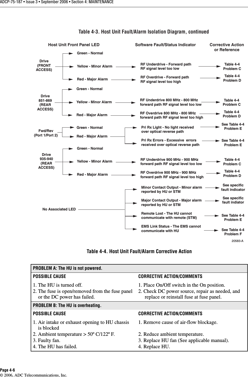
ADC Telecommunications DSC0802P Digivance SCS 800 MHz and 1900 MHz System User Manual 75187
ADC Telecommunications Inc Digivance SCS 800 MHz and 1900 MHz System 75187
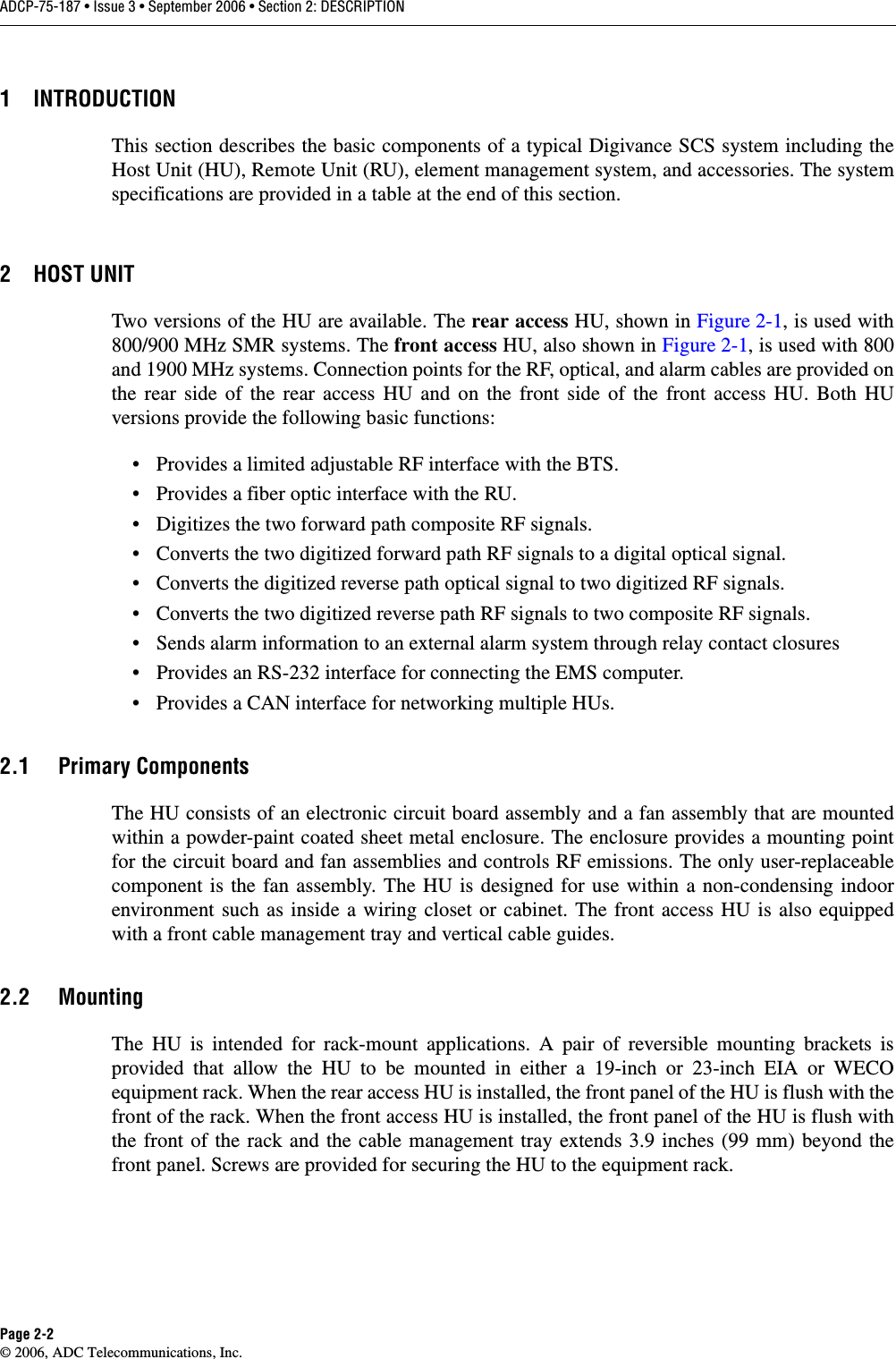
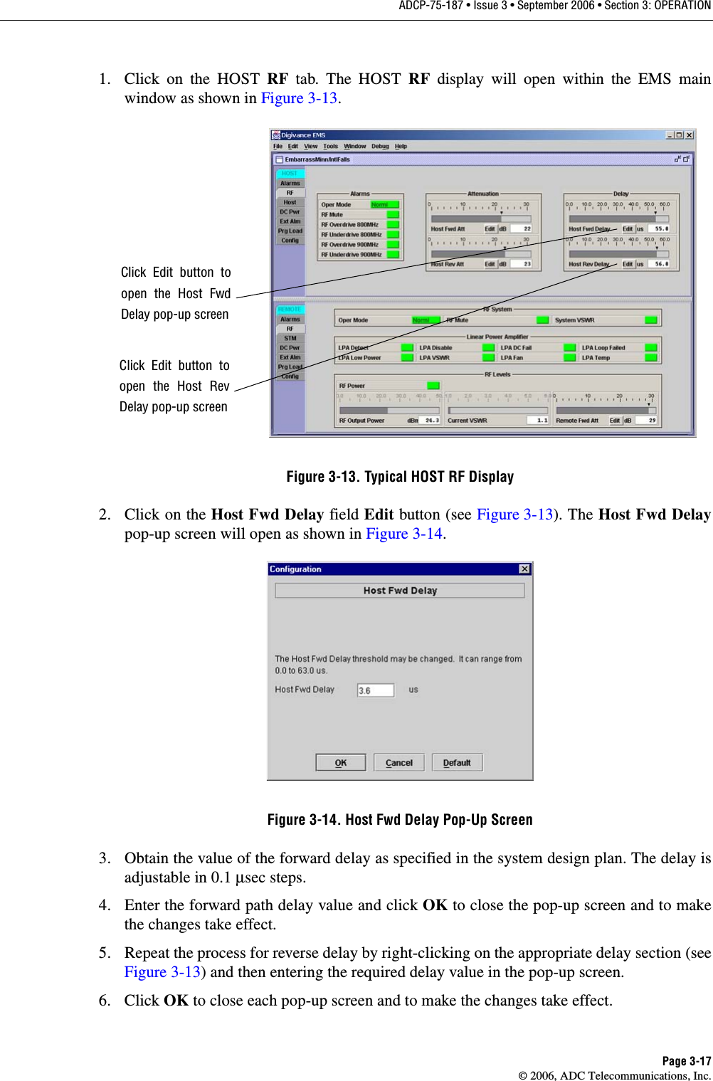
UserManual.wiki
>
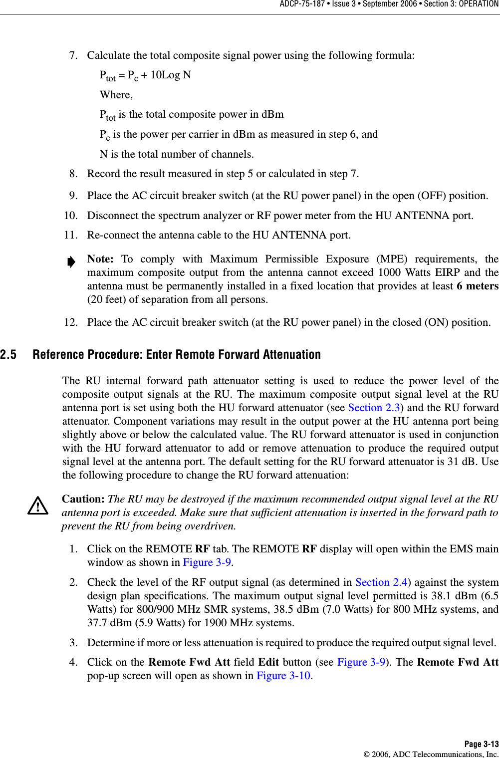
ADC Telecommunications
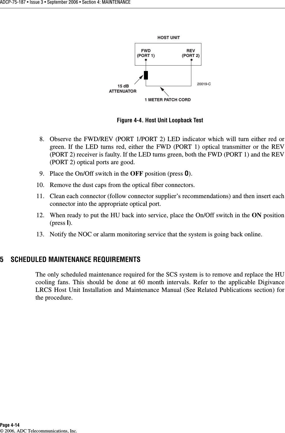
>
DSC0802P User Manual
>
Manual
Contents
1.
Manual
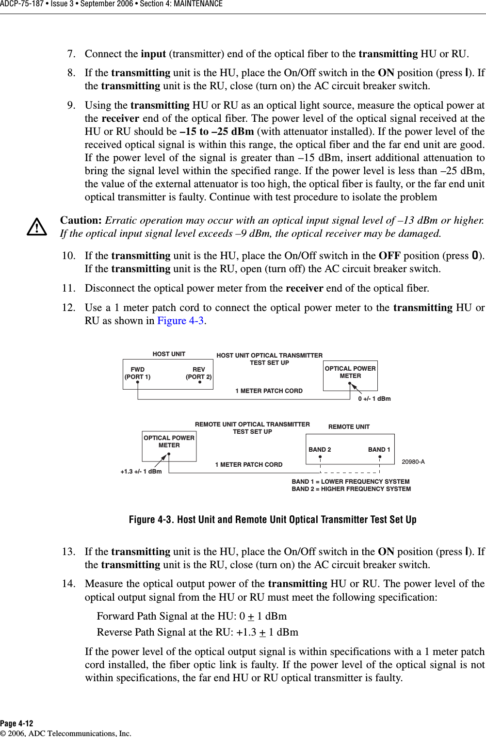
2.
Brochure
Manual
Navigation menu
Upload a User Manual
Namespaces
Wiki Guide
HTML
PDF
Info
Views
User Manual
Discussion / Help
Navigation