ADC Telecommunications DSC0802P Digivance SCS 800 MHz and 1900 MHz System User Manual 75187
ADC Telecommunications Inc Digivance SCS 800 MHz and 1900 MHz System 75187
Contents
- 1. Manual
- 2. Brochure
Manual
ADCP-75-187
Issue 3
September 2006
1346357 Rev B
Digivance® Street-Level Coverage Solution
800 MHz, 1900 MHz, and 800/900 MHz SMR
System Operation and Maintenance Manual
20576-A

ADCP-75-187
Issue 3
September 2006
1346357 Rev B
Digivance® Street-Level Coverage Solution
800 MHz, 1900 MHz, 800/900 MHz SMR
System Operation and Maintenance Manual

ADCP-75-187 • Issue 3 • September 2006 • Preface
Page ii
COPYRIGHT
© 2006, ADC Telecommunications, Inc.
All Rights Reserved
REVISION HISTORY
LIST OF CHANGES
The technical changes incorporated into this issue are listed below.
TRADEMARK INFORMATION
ADC and Digivance are registered trademarks of ADC Telecommunications, Inc.
OptiTap is a trademark of Corning Incorporated.
Stargazer is a registered trademark of ADC DSL Systems, Inc.
Procomm Plus is a registered trademark of Quarterdeck Corporation.
Acrobat and Adobe are registered trademarks of Adobe Systems, Inc.
DISCLAIMER OF LIABILITY
Contents herein are current as of the date of publication. ADC reserves the right to change the contents without prior notice. In no
event shall ADC be liable for any damages resulting from loss of data, loss of use, or loss of profits and ADC further
disclaims any and all liability for indirect, incidental, special, consequential or other similar damages. This disclaimer of
liability applies to all products, publications and services during and after the warranty period.
This publication may be verified at any time by contacting ADC’s Technical Assistance Center at 1-800-366-3891, extension 73476
(in U.S.A. or Canada) or 952-917-3476 (outside U.S.A. and Canada), or by e-mail to wireless.tac@adc.com
ISSUE DATE REASON FOR CHANGE
1 09/2005 Original issue.
2 06/2006 Release of single-band and dual-band remote units that support 800 and 1900 MHz operation and inclu-
sion of the RLM feature in the 800 and 1900 MHz remote units.
3 09/2006 Non-technical changes for agency approvals.
PAGE IDENTIFIER DESCRIPTION OF CHANGE
ix Standards Added FCC Part 15.5 statement.
2-25 Table 2-7 Deleted references to 1900 MHz Band G
ADC Telecommunications, Inc.
P.O. Box 1101, Minneapolis, Minnesota 55440-1101
In U.S.A. and Canada: 1-800-366-3891
Outside U.S.A. and Canada: (952) 938-8080
Fax: (952) 917-1717

ADCP-75-187 • Issue 3 • September 2006 • Preface
Page iii
© 2006, ADC Telecommunications, Inc.
TABLE OF CONTENTS
Content Page
ABOUT THIS MANUAL . . . . . . . . . . . . . . . . . . . . . . . . . . . . . . . . . . . . . . . . . . . . . . . . . . . . . . . . . . . . . . . . . . . . . . . . vii
RELATED PUBLICATIONS . . . . . . . . . . . . . . . . . . . . . . . . . . . . . . . . . . . . . . . . . . . . . . . . . . . . . . . . . . . . . . . . . . . . . . vii
ADMONISHMENTS . . . . . . . . . . . . . . . . . . . . . . . . . . . . . . . . . . . . . . . . . . . . . . . . . . . . . . . . . . . . . . . . . . . . . . . . . . viii
GENERAL SAFETY PRECAUTIONS . . . . . . . . . . . . . . . . . . . . . . . . . . . . . . . . . . . . . . . . . . . . . . . . . . . . . . . . . . . . . . . .viii
STANDARDS CERTIFICATION . . . . . . . . . . . . . . . . . . . . . . . . . . . . . . . . . . . . . . . . . . . . . . . . . . . . . . . . . . . . . . . . . . . .ix
LIST OF ACRONYMS AND ABBREVIATIONS . . . . . . . . . . . . . . . . . . . . . . . . . . . . . . . . . . . . . . . . . . . . . . . . . . . . . . . . . . . x
SECTION 1:
OVERVIEW
1 INTRODUCTION. . . . . . . . . . . . . . . . . . . . . . . . . . . . . . . . . . . . . . . . . . . . . . . . . . . . . . . . . . . . . . . . . . . . . . . .1-1
2 SCS SYSTEM OVERVIEW . . . . . . . . . . . . . . . . . . . . . . . . . . . . . . . . . . . . . . . . . . . . . . . . . . . . . . . . . . . . . . . . .1-1
2.1 Basic SCS System Components . . . . . . . . . . . . . . . . . . . . . . . . . . . . . . . . . . . . . . . . . . . . . . . . . . . . . . .1-1
2.2 Enhanced Base Transceiver Station Interface. . . . . . . . . . . . . . . . . . . . . . . . . . . . . . . . . . . . . . . . . . . . . .1-3
2.3 Subscriber Unit Interface . . . . . . . . . . . . . . . . . . . . . . . . . . . . . . . . . . . . . . . . . . . . . . . . . . . . . . . . . . .1-3
2.4 Local Management Interface. . . . . . . . . . . . . . . . . . . . . . . . . . . . . . . . . . . . . . . . . . . . . . . . . . . . . . . . .1-3
2.5 Network Operations Center Interface . . . . . . . . . . . . . . . . . . . . . . . . . . . . . . . . . . . . . . . . . . . . . . . . . . .1-5
2.6 SNMP Interface . . . . . . . . . . . . . . . . . . . . . . . . . . . . . . . . . . . . . . . . . . . . . . . . . . . . . . . . . . . . . . . . . .1-6
3 SYSTEM FUNCTIONS AND FEATURES. . . . . . . . . . . . . . . . . . . . . . . . . . . . . . . . . . . . . . . . . . . . . . . . . . . . . . . . .1-7
3.1 Fiber Optic Transport . . . . . . . . . . . . . . . . . . . . . . . . . . . . . . . . . . . . . . . . . . . . . . . . . . . . . . . . . . . . . .1-7
3.2 Control and Monitoring Software . . . . . . . . . . . . . . . . . . . . . . . . . . . . . . . . . . . . . . . . . . . . . . . . . . . . . .1-8
3.3 Fault Detection and Alarm Reporting . . . . . . . . . . . . . . . . . . . . . . . . . . . . . . . . . . . . . . . . . . . . . . . . . . .1-8
3.4 Powering . . . . . . . . . . . . . . . . . . . . . . . . . . . . . . . . . . . . . . . . . . . . . . . . . . . . . . . . . . . . . . . . . . . . . .1-8
3.5 Equipment Mounting and Location . . . . . . . . . . . . . . . . . . . . . . . . . . . . . . . . . . . . . . . . . . . . . . . . . . . . .1-8
4 DUAL-BAND REMOTE UNIT SCS SYSTEMS . . . . . . . . . . . . . . . . . . . . . . . . . . . . . . . . . . . . . . . . . . . . . . . . . . . . .1-9
SECTION 2:
DESCRIPTION
1 INTRODUCTION. . . . . . . . . . . . . . . . . . . . . . . . . . . . . . . . . . . . . . . . . . . . . . . . . . . . . . . . . . . . . . . . . . . . . . . .2-2
2 HOST UNIT . . . . . . . . . . . . . . . . . . . . . . . . . . . . . . . . . . . . . . . . . . . . . . . . . . . . . . . . . . . . . . . . . . . . . . . . . . .2-2
2.1 Primary Components . . . . . . . . . . . . . . . . . . . . . . . . . . . . . . . . . . . . . . . . . . . . . . . . . . . . . . . . . . . . . .2-2
2.2 Mounting . . . . . . . . . . . . . . . . . . . . . . . . . . . . . . . . . . . . . . . . . . . . . . . . . . . . . . . . . . . . . . . . . . . . . .2-2
2.3 Fault Detection and Alarm Reporting . . . . . . . . . . . . . . . . . . . . . . . . . . . . . . . . . . . . . . . . . . . . . . . . . . .2-3
2.4 RF Signal Connections . . . . . . . . . . . . . . . . . . . . . . . . . . . . . . . . . . . . . . . . . . . . . . . . . . . . . . . . . . . . .2-4
2.5 RF Signal Level Adjustments. . . . . . . . . . . . . . . . . . . . . . . . . . . . . . . . . . . . . . . . . . . . . . . . . . . . . . . . .2-4
2.6 Propagation Delay . . . . . . . . . . . . . . . . . . . . . . . . . . . . . . . . . . . . . . . . . . . . . . . . . . . . . . . . . . . . . . . .2-4
2.7 Optical Connection . . . . . . . . . . . . . . . . . . . . . . . . . . . . . . . . . . . . . . . . . . . . . . . . . . . . . . . . . . . . . . .2-4
2.8 Controller Area Network Interface Connection . . . . . . . . . . . . . . . . . . . . . . . . . . . . . . . . . . . . . . . . . . . . .2-5
2.9 Service Interface Connection. . . . . . . . . . . . . . . . . . . . . . . . . . . . . . . . . . . . . . . . . . . . . . . . . . . . . . . . .2-5
2.10 Powering . . . . . . . . . . . . . . . . . . . . . . . . . . . . . . . . . . . . . . . . . . . . . . . . . . . . . . . . . . . . . . . . . . . . . .2-5
2.11 Cooling . . . . . . . . . . . . . . . . . . . . . . . . . . . . . . . . . . . . . . . . . . . . . . . . . . . . . . . . . . . . . . . . . . . . . . .2-5

ADCP-75-187 • Issue 3 • September 2006 • Preface
Page iv
© 2006, ADC Telecommunications, Inc.
TABLE OF CONTENTS
Content Page
2.12 User Interface. . . . . . . . . . . . . . . . . . . . . . . . . . . . . . . . . . . . . . . . . . . . . . . . . . . . . . . . . . . . . . . . . . . 2-5
3 REMOTE UNIT . . . . . . . . . . . . . . . . . . . . . . . . . . . . . . . . . . . . . . . . . . . . . . . . . . . . . . . . . . . . . . . . . . . . . . . . 2-9
3.1 Primary Components . . . . . . . . . . . . . . . . . . . . . . . . . . . . . . . . . . . . . . . . . . . . . . . . . . . . . . . . . . . . . . 2-9
3.2 Mounting . . . . . . . . . . . . . . . . . . . . . . . . . . . . . . . . . . . . . . . . . . . . . . . . . . . . . . . . . . . . . . . . . . . . . 2-10
3.3 Fault Detection and Alarm Reporting . . . . . . . . . . . . . . . . . . . . . . . . . . . . . . . . . . . . . . . . . . . . . . . . . . 2-10
3.4 Antenna Cable Connection . . . . . . . . . . . . . . . . . . . . . . . . . . . . . . . . . . . . . . . . . . . . . . . . . . . . . . . . . 2-11
3.5 RF Signal Level Adjustment . . . . . . . . . . . . . . . . . . . . . . . . . . . . . . . . . . . . . . . . . . . . . . . . . . . . . . . . 2-11
3.6 Optical Connection . . . . . . . . . . . . . . . . . . . . . . . . . . . . . . . . . . . . . . . . . . . . . . . . . . . . . . . . . . . . . . 2-11
3.7 Powering . . . . . . . . . . . . . . . . . . . . . . . . . . . . . . . . . . . . . . . . . . . . . . . . . . . . . . . . . . . . . . . . . . . . . 2-11
3.8 Grounding . . . . . . . . . . . . . . . . . . . . . . . . . . . . . . . . . . . . . . . . . . . . . . . . . . . . . . . . . . . . . . . . . . . . 2-12
3.9 Cooling . . . . . . . . . . . . . . . . . . . . . . . . . . . . . . . . . . . . . . . . . . . . . . . . . . . . . . . . . . . . . . . . . . . . . . 2-12
3.10 User Interface. . . . . . . . . . . . . . . . . . . . . . . . . . . . . . . . . . . . . . . . . . . . . . . . . . . . . . . . . . . . . . . . . . 2-12
4 ACCESSORY ITEMS. . . . . . . . . . . . . . . . . . . . . . . . . . . . . . . . . . . . . . . . . . . . . . . . . . . . . . . . . . . . . . . . . . . . 2-14
4.1 Strand Mount Kit for RU . . . . . . . . . . . . . . . . . . . . . . . . . . . . . . . . . . . . . . . . . . . . . . . . . . . . . . . . . . . 2-14
4.2 Lightning Protector for RU . . . . . . . . . . . . . . . . . . . . . . . . . . . . . . . . . . . . . . . . . . . . . . . . . . . . . . . . . 2-14
4.3 Solar Shields . . . . . . . . . . . . . . . . . . . . . . . . . . . . . . . . . . . . . . . . . . . . . . . . . . . . . . . . . . . . . . . . . . 2-15
5 DIGIVANCE ELEMENT MANAGEMENT SYSTEM . . . . . . . . . . . . . . . . . . . . . . . . . . . . . . . . . . . . . . . . . . . . . . . . . 2-15
5.1 Digivance EMS Primary Components . . . . . . . . . . . . . . . . . . . . . . . . . . . . . . . . . . . . . . . . . . . . . . . . . . 2-15
5.2 Software Installation . . . . . . . . . . . . . . . . . . . . . . . . . . . . . . . . . . . . . . . . . . . . . . . . . . . . . . . . . . . . . 2-16
5.3 Computer Operation . . . . . . . . . . . . . . . . . . . . . . . . . . . . . . . . . . . . . . . . . . . . . . . . . . . . . . . . . . . . . 2-16
5.4 Digivance EMS Computer Interface Connections . . . . . . . . . . . . . . . . . . . . . . . . . . . . . . . . . . . . . . . . . . 2-16
5.5 Digivance Software User Interfaces . . . . . . . . . . . . . . . . . . . . . . . . . . . . . . . . . . . . . . . . . . . . . . . . . . . 2-17
6 SPECIFICATIONS . . . . . . . . . . . . . . . . . . . . . . . . . . . . . . . . . . . . . . . . . . . . . . . . . . . . . . . . . . . . . . . . . . . . . 2-19
SECTION 3:
OPERATION
1 BEFORE STARTING OPERATION . . . . . . . . . . . . . . . . . . . . . . . . . . . . . . . . . . . . . . . . . . . . . . . . . . . . . . . . . . . . 3-1
1.1 Tools and Materials. . . . . . . . . . . . . . . . . . . . . . . . . . . . . . . . . . . . . . . . . . . . . . . . . . . . . . . . . . . . . . . 3-1
1.2 Readiness Check . . . . . . . . . . . . . . . . . . . . . . . . . . . . . . . . . . . . . . . . . . . . . . . . . . . . . . . . . . . . . . . . 3-2
2 TURN-UP SYSTEM AND VERIFY OPERATION. . . . . . . . . . . . . . . . . . . . . . . . . . . . . . . . . . . . . . . . . . . . . . . . . . . . 3-2
2.1 Reference Procedure: Determine Forward Path Input Signal Level. . . . . . . . . . . . . . . . . . . . . . . . . . . . . . . 3-6
2.2 Reference Procedure: Enter Site Name and Site Number . . . . . . . . . . . . . . . . . . . . . . . . . . . . . . . . . . . . .3-9
2.3 Reference Procedure: Enter Host Forward Attenuation . . . . . . . . . . . . . . . . . . . . . . . . . . . . . . . . . . . . . . 3-11
2.4 Reference Procedure: Determine Output Signal Level at RU Antenna Port. . . . . . . . . . . . . . . . . . . . . . . . . 3-12
2.5 Reference Procedure: Enter Remote Forward Attenuation . . . . . . . . . . . . . . . . . . . . . . . . . . . . . . . . . . . . 3-13
2.6 Reference Procedure: Enter Host Reverse Attenuation . . . . . . . . . . . . . . . . . . . . . . . . . . . . . . . . . . . . . . 3-15
2.7 Reference Procedure: Enter Host Forward and Reverse Delay . . . . . . . . . . . . . . . . . . . . . . . . . . . . . . . . . 3-16

ADCP-75-187 • Issue 3 • September 2006 • Preface
Page v
© 2006, ADC Telecommunications, Inc.
TABLE OF CONTENTS
Content Page
SECTION 4:
MAINTENANCE
1 SYSTEM MAINTENANCE OVERVIEW . . . . . . . . . . . . . . . . . . . . . . . . . . . . . . . . . . . . . . . . . . . . . . . . . . . . . . . . . .4-1
1.1 Tools and Materials . . . . . . . . . . . . . . . . . . . . . . . . . . . . . . . . . . . . . . . . . . . . . . . . . . . . . . . . . . . . . . .4-1
2 FAULT DETECTION AND ALARM REPORTING . . . . . . . . . . . . . . . . . . . . . . . . . . . . . . . . . . . . . . . . . . . . . . . . . . . .4-2
3 FAULT ISOLATION AND TROUBLESHOOTING . . . . . . . . . . . . . . . . . . . . . . . . . . . . . . . . . . . . . . . . . . . . . . . . . . . .4-4
3.1 Host Unit Troubleshooting. . . . . . . . . . . . . . . . . . . . . . . . . . . . . . . . . . . . . . . . . . . . . . . . . . . . . . . . . . .4-5
3.2 RU Troubleshooting . . . . . . . . . . . . . . . . . . . . . . . . . . . . . . . . . . . . . . . . . . . . . . . . . . . . . . . . . . . . . . .4-7
4 TEST PROCEDURES . . . . . . . . . . . . . . . . . . . . . . . . . . . . . . . . . . . . . . . . . . . . . . . . . . . . . . . . . . . . . . . . . . . . 4-11
4.1 Optical Power Test. . . . . . . . . . . . . . . . . . . . . . . . . . . . . . . . . . . . . . . . . . . . . . . . . . . . . . . . . . . . . . . 4-11
4.2 Optical Loopback Test . . . . . . . . . . . . . . . . . . . . . . . . . . . . . . . . . . . . . . . . . . . . . . . . . . . . . . . . . . . . 4-13
5 SCHEDULED MAINTENANCE REQUIREMENTS . . . . . . . . . . . . . . . . . . . . . . . . . . . . . . . . . . . . . . . . . . . . . . . . . . 4-14
SECTION 5:
GENERAL INFORMATION
1 WARRANTY/SOFTWARE . . . . . . . . . . . . . . . . . . . . . . . . . . . . . . . . . . . . . . . . . . . . . . . . . . . . . . . . . . . . . . . . . .5-1
2 SOFTWARE SERVICE AGREEMENT . . . . . . . . . . . . . . . . . . . . . . . . . . . . . . . . . . . . . . . . . . . . . . . . . . . . . . . . . . .5-1
3 REPAIR/EXCHANGE POLICY . . . . . . . . . . . . . . . . . . . . . . . . . . . . . . . . . . . . . . . . . . . . . . . . . . . . . . . . . . . . . . .5-1
4 REPAIR CHARGES . . . . . . . . . . . . . . . . . . . . . . . . . . . . . . . . . . . . . . . . . . . . . . . . . . . . . . . . . . . . . . . . . . . . . .5-2
5 REPLACEMENT/SPARE PRODUCTS . . . . . . . . . . . . . . . . . . . . . . . . . . . . . . . . . . . . . . . . . . . . . . . . . . . . . . . . . .5-2
6 RETURNED MATERIAL . . . . . . . . . . . . . . . . . . . . . . . . . . . . . . . . . . . . . . . . . . . . . . . . . . . . . . . . . . . . . . . . . . .5-2
7 CUSTOMER INFORMATION AND ASSISTANCE . . . . . . . . . . . . . . . . . . . . . . . . . . . . . . . . . . . . . . . . . . . . . . . . . . .5-3

ADCP-75-187 • Issue 3 • September 2006 • Preface
Page vi
© 2006, ADC Telecommunications, Inc.
TABLE OF CONTENTS
Content Page
Blank

ADCP-75-187 • Issue 3 • September 2006 • Preface
Page vii
© 2006, ADC Telecommunications, Inc.
ABOUT THIS MANUAL
This operation and maintenance manual provides the following information:
• An overview of the Digivance Street-Level Coverage Solution (SCS) system.
• A basic description of the system components including the Host Unit (HU), Remote Unit
(RU), and Digivance Element Management System (EMS).
• Procedures for turning-up the system and verifying that the system is functioning properly.
• Procedures for maintaining the system including scheduled maintenance tasks and fault
isolation and troubleshooting procedures.
• Product warranty, repair, return, and replacement information.
The procedures for installing the host unit, remote unit, and for installing and using the EMS
software are provided in other publications which are referenced in the Related Publications
section and at appropriate points within this manual.
RELATED PUBLICATIONS
Listed below are related manuals, their content, and their publication numbers. Copies of these
publications can be ordered by contacting the Technical Assistance Center at 1-800-366-3891,
extension 73476 (in U.S.A. or Canada) or 952-917-3476 (outside U.S.A. and Canada).
Digivance LRCS and SCS Systems 800/900 MHz SMR Rear Access
Host Unit Installation and Maintenance Manual 75-180
Provides instructions for mounting the rear access host unit in an equipment
rack, installing and connecting the various cables, and replacing the cooling fans.
Digivance SCS System Interim Single-Band Remote Unit Installation Manual 75-190
Provides instructions for mounting the interim single-band remote unit and for
installing and connecting the various cables.
Digivance SCS System Single-Band Remote Unit Installation Manual 75-188
Provides instructions for mounting the single-band remote unit and for
installing and connecting the various cables.
Digivance SCS System Dual-Band Remote Unit Installation and
Maintenance Manual 75-189
Provides instructions for mounting the dual-band remote unit and for installing
and connecting the various cables.
Digivance Element Management System Version 7.0 User Manual 75-201
Provides instructions for installing the Digivance Element Management System
(EMS) software and for using both the Graphical User Interface (GUI) and the
Network Operations Center (NOC) versions of the software.
Digivance SNMP Agent Software Version 7.1 User Manual 75-202
Describes how to install, configure, and use the LRCS SNMP Proxy Agent.
Title/Description ADCP Number

ADCP-75-187 • Issue 3 • September 2006 • Preface
Page viii
© 2006, ADC Telecommunications, Inc.
ADMONISHMENTS
Important safety admonishments are used throughout this manual to warn of possible hazards to
persons or equipment. An admonishment identifies a possible hazard and then explains what
may happen if the hazard is not avoided. The admonishments — in the form of Dangers,
Warnings, and Cautions — must be followed at all times. These warnings are flagged by use of
the triangular alert icon (seen below), and are listed in descending order of severity of injury or
damage and likelihood of occurrence.
GENERAL SAFETY PRECAUTIONS
Danger: Danger is used to indicate the presence of a hazard that will cause severe personal
injury, death, or substantial property damage if the hazard is not avoided.
Warning: Warning is used to indicate the presence of a hazard that can cause severe personal
injury, death, or substantial property damage if the hazard is not avoided.
Caution: Caution is used to indicate the presence of a hazard that will or can cause minor
personal injury or property damage if the hazard is not avoided.
Danger: This equipment uses a Class 1 Laser according to FDA/CDRH rules. Laser radiation
can seriously damage the retina of the eye. Do not look into the ends of any optical fiber. Do not
look directly into the optical transceiver of any digital unit or exposure to laser radiation may
result. An optical power meter should be used to verify active fibers. A protective cap or hood
MUST be immediately placed over any radiating transceiver or optical fiber connector to avoid
the potential of dangerous amounts of radiation exposure. This practice also prevents dirt
particles from entering the adapter or connector.
Danger: Do not look into the ends of any optical fiber. Exposure to laser radiation may result.
Do not assume laser power is turned-off or the fiber is disconnected at the other end.
Danger: Wet conditions increase the potential for receiving an electrical shock when installing
or using electrically-powered equipment. To prevent electrical shock, never install or use
electrical equipment in a wet location or during a lightning storm.
Warning: The HU is powered by 48 VDC power which is supplied over customer-provided
wiring. To prevent electrical shock when installing or modifying the HU power wiring,
disconnect the wiring at the power source before working with uninsulated wires or terminals.
Caution: Always allow sufficient fiber length to permit routing of patch cords and pigtails
without severe bends. Fiber optic patch cords or pigtails may be permanently damaged if bent
or curved to a radius of less than 2 inches (50 mm).

ADCP-75-187 • Issue 3 • September 2006 • Preface
Page ix
© 2006, ADC Telecommunications, Inc.
STANDARDS CERTIFICATION
Each respective SMR, Cellular, and PCS system in the SCS platform is FCC and IC approved.
Information in this manual explains applicable portions of these systems.
FCC: The Digivance SCS system complies with the applicable sections of Title 47 CFR Parts
22, 24, and 90. Installation requirements the licensee needs to follow are listed in Title 47 CFR
90.635. This document may be found at the following website: http://www.access.gpo.gov/nara/
cfr/waisidx_03/47cfr90_03.html.
Caution: Modifications not expressly approved by the party responsible for compliance
could void the user’s authority to operate the equipment.
Part 15.5 General conditions of operation:
a. Persons operating intentional or unintentional radiators shall not be deemed to have
any vested or recognizable right to continue use of any given frequency by virtue of
prior registration or certificate of equipment.
b. Operation of an intentional, unintentional, or incidental radiator is subject to the
conditions that no harmful interference is caused and that interference must be
accepted that may be caused by the operation of an authorized radio station, by
another intentional or unintentional radiator, by industrial, scientific and medical
(ISM) equipment, or by an incidental operator.
c. The operator of a radio frequency device shall be required to cease operating the
device upon notification by a Commission representative that the device is causing
harmful interference. Operation shall not resume until the condition causing the
harmful interference has been corrected.
UL/CUL: The Host Unit complies with UL and CUL 60950 Standard for Safety for
Information Technology Equipment including Electrical Business Equipment.
The Remote Unit complies with NEMA Type 6, UL and CUL 50, Standard for Enclosures for
Electrical Equipment.
The Remote Unit provides the degree of protection specified by IP67 as defined in IEC
(International Electrotechnical Commission) Publication 60529.
The Remote Unit complies with UL and CUL 60950 and UL 50 as Communication Service
Equipment under the DUZO category.
FDA/CDRH: This equipment uses a Class 1 LASER according to FDA/CDRH Rules. This
product conforms to all applicable standards of 21 CFR Part 1040.
IC: This equipment complies with the applicable sections of RSS-131. The term “IC:” before the
radio certification number only signifies that Industry Canada Technical Specifications were met.

ADCP-75-187 • Issue 3 • September 2006 • Preface
Page x
© 2006, ADC Telecommunications, Inc.
LIST OF ACRONYMS AND ABBREVIATIONS
The acronyms and abbreviations used in this manual are detailed in the following list:
AC Alternating Current
ASCII American Standard Code for Information Interchange
Att Attenuation
AW G American Wire Gauge
BER Bit Error Rate
CCentigrade
CAN Controller Area Network
CDRH Center for Devices and Radiological Health
CD-ROM Compact Disk Read Only Memory
COM Common
COMM Communication
Config Configuration
CUL Canadian Underwriters Laboratories
DC Direct Current
DCE Data Communications Equipment
DTE Data Terminal Equipment
EBTS Enhanced Base Transceiver Station
EIA Electronic Industries Association
EMS Element Management System
ESD Electrostatic Discharge
FFahrenheit
FCC Federal Communications Commission
FDA Food and Drug Administration
FWD Forward
GUI Graphical User Interface
HU Host Unit
IC Industry Canada
IEC International Electrotechnical Commission
IP Internet Protocol
LED Light Emitting Diode
LPA Linear Power Amplifier
LRCS Long-Range Coverage Solution
MHz Mega Hertz
MIB Management Information Base
MPE Maximum Permissible Exposure
MTBF Mean Time Between Failure
NC Normally Closed
NEM Network Element Manager
NO Normally Open
NOC Network Operations Center

ADCP-75-187 • Issue 3 • September 2006 • Preface
Page xi
© 2006, ADC Telecommunications, Inc.
OSP Outside Plant
PA Power Amplifier
PC Personal Computer
PCS Personal Communications System
Rev Reverse
RF Radio Frequency
RMA Return Material Authorization
RU Remote Unit
RX Receive or Receiver
SCS Street-Level Coverage Solution
SNMP Simple Network Management Protocol
SMR Specialized Mobile Radio
STM Spectrum Transport Module
TX Transmit or Transmitter
UL Underwriters Laboratories
VAC Volts Alternating Current
VDC Volts Direct Current
VSWR Voltage Standing Wave Ratio
WDM Wavelength Division Multiplexer
WECO Western Electric Company

ADCP-75-187 • Issue 3 • September 2006 • Preface
Page xii
© 2006, ADC Telecommunications, Inc.
Blank

ADCP-75-187 • Issue 3 • September 2006 • Section 1: OVERVIEW
Page 1-1
© 2006, ADC Telecommunications, Inc.
SECTION 1: OVERVIEW
1 INTRODUCTION. . . . . . . . . . . . . . . . . . . . . . . . . . . . . . . . . . . . . . . . . . . . . . . . . . . . . . . . . . . . . . . . . . . . . . . .1-1
2 SCS SYSTEM OVERVIEW . . . . . . . . . . . . . . . . . . . . . . . . . . . . . . . . . . . . . . . . . . . . . . . . . . . . . . . . . . . . . . . . .1-1
2.1 Basic SCS System Components . . . . . . . . . . . . . . . . . . . . . . . . . . . . . . . . . . . . . . . . . . . . . . . . . . . . . . .1-1
2.2 Enhanced Base Transceiver Station Interface. . . . . . . . . . . . . . . . . . . . . . . . . . . . . . . . . . . . . . . . . . . . . .1-3
2.3 Subscriber Unit Interface . . . . . . . . . . . . . . . . . . . . . . . . . . . . . . . . . . . . . . . . . . . . . . . . . . . . . . . . . . .1-3
2.4 Local Management Interface. . . . . . . . . . . . . . . . . . . . . . . . . . . . . . . . . . . . . . . . . . . . . . . . . . . . . . . . .1-3
2.5 Network Operations Center Interface . . . . . . . . . . . . . . . . . . . . . . . . . . . . . . . . . . . . . . . . . . . . . . . . . . .1-5
2.6 SNMP Interface . . . . . . . . . . . . . . . . . . . . . . . . . . . . . . . . . . . . . . . . . . . . . . . . . . . . . . . . . . . . . . . . . .1-6
3 SYSTEM FUNCTIONS AND FEATURES. . . . . . . . . . . . . . . . . . . . . . . . . . . . . . . . . . . . . . . . . . . . . . . . . . . . . . . . .1-7
3.1 Fiber Optic Transport . . . . . . . . . . . . . . . . . . . . . . . . . . . . . . . . . . . . . . . . . . . . . . . . . . . . . . . . . . . . . .1-7
3.2 Control and Monitoring Software . . . . . . . . . . . . . . . . . . . . . . . . . . . . . . . . . . . . . . . . . . . . . . . . . . . . . .1-8
3.3 Fault Detection and Alarm Reporting . . . . . . . . . . . . . . . . . . . . . . . . . . . . . . . . . . . . . . . . . . . . . . . . . . .1-8
3.4 Powering . . . . . . . . . . . . . . . . . . . . . . . . . . . . . . . . . . . . . . . . . . . . . . . . . . . . . . . . . . . . . . . . . . . . . .1-8
3.5 Equipment Mounting and Location . . . . . . . . . . . . . . . . . . . . . . . . . . . . . . . . . . . . . . . . . . . . . . . . . . . . .1-8
4 DUAL-BAND REMOTE UNIT SCS SYSTEMS . . . . . . . . . . . . . . . . . . . . . . . . . . . . . . . . . . . . . . . . . . . . . . . . . . . . .1-9
_________________________________________________________________________________________________________
1 INTRODUCTION
This section provides basic description, application, and configuration information about the
Digivance SCS system. Throughout this publication, all items referenced as “accessory items”
are not furnished with the basic product and must be purchased separately.
2 SCS SYSTEM OVERVIEW
The Digivance Long Range Coverage Solution (LRCS) system is an RF signal transport system
that provides long-range RF coverage to areas where it is impractical to place an Enhanced Base
Transceiver Station (EBTS) at the antenna site. High real estate costs and community
restrictions on tower and equipment locations often make it difficult to install the EBTS at the
same location as the antenna. The LRCS system overcomes equipment placement problems by
hubbing base stations at a central location and placing antennas at remote locations with
minimal real estate requirements. The LRCS system transports RF signals to remote locations to
expand coverage into areas not receiving service or to extend coverage into difficult to reach
areas such as canyons, tunnels, or underground roadways.
The SCS system provides the same functionality as the LRCS system but incorporates a low
profile, low power, low cost remote unit. The SCS system remote unit complements the high
power remote unit used with LRCS systems. The primary application includes urban areas
where multiple, strategically placed, low power remote units provide better coverage than high
power remote units.
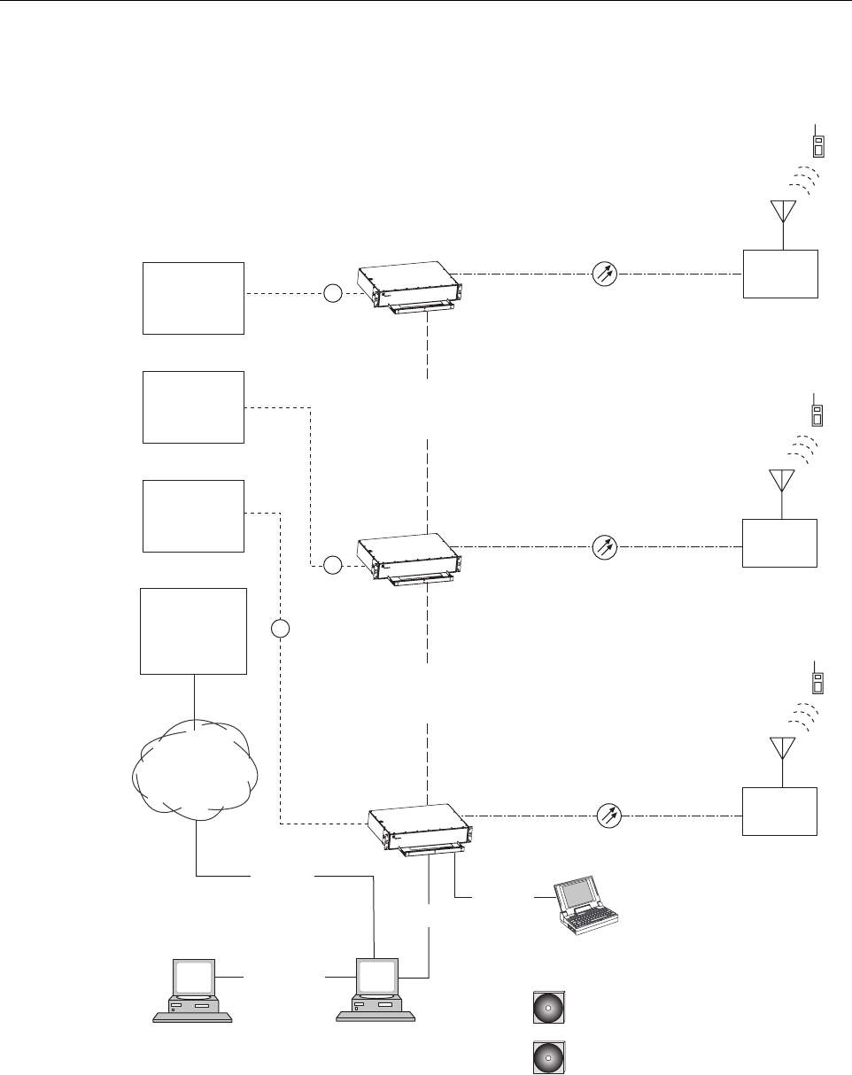
2.1 Basic SCS System Components
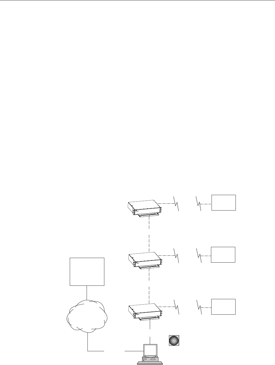
The basic components of a typical Digivance SCS system and their function are shown in
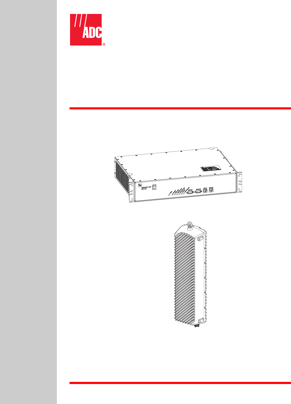
Figure 1-1. A basic SCS system consists of a Host Unit (HU) and a Remote Unit (RU). The HU
consists of a rack-mountable chassis that is designed for use in an indoor environment. The RU
consists of a sealed enclosure that is designed for use in an outdoor environment. Control and
monitoring functions are provided by the Digivance Element Management System (EMS).
ADCP-75-187 • Issue 3 • September 2006 • Section 1: OVERVIEW
Page 1-2
© 2006, ADC Telecommunications, Inc.
Figure 1-1. SCS System Overview Diagram
HOST UNIT 1
HOST UNIT 2
HOST UNIT 3
NETWORK
OPERATIONS
CENTER
(REMOTE
INTERFACE)
CONTROLLER
AREA
NETWORK
20564-B
RF
RF
RF
CONTROLLER
AREA
NETWORK
REMOTE
UNIT 1
REMOTE
UNIT 3
REMOTE
UNIT 2
PC COMPUTER WITH EMS
AND SNMP PROXY AGENT
(PERMANENT CONNECTION)
RS-232
ASCII
RS-232
CD-ROM WITH EMS
SOFTWARE
NETWORK SNMP
MANAGER
CD-ROM WITH SNMP PROXY
AGENT SOFTWARE (OPTIONAL)
ETHERNET
LAN
PC COMPUTER WITH EMS
(TEMPORARY CONNECTION)
T1, DS0
WITH RS232
CONVERSION,
OR OTHER
MEDIUM
RS-232
ENHANCED
BASE
TRANSCEIVER
STATION 1
ENHANCED
BASE
TRANSCEIVER
STATION 2
ENHANCED
BASE
TRANSCEIVER
STATION 3
ADCP-75-187 • Issue 3 • September 2006 • Section 1: OVERVIEW
Page 1-3
© 2006, ADC Telecommunications, Inc.
2.2 Enhanced Base Transceiver Station Interface
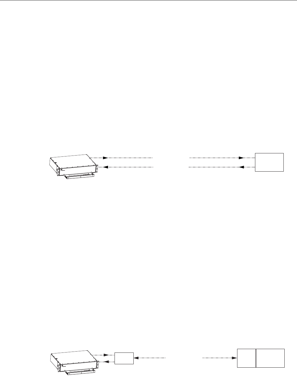
The HU is interfaced with an EBTS over coaxial cables as shown in Figure 1-2. The EBTS
provides the RF channel inputs and outputs for a designated sector. In the forward path, the HU
receives two RF inputs from the EBTS. The HU digitizes the RF spectrum and then converts it
to digital optical signals for transport to the RU. In the reverse path, the HU receives digital
optical signals from the RU. The HU converts the digital optical signals back to two RF outputs
which are supplied to the EBTS over the coaxial cable interface.
Figure 1-2. EBTS/HU Interface
2.3 Subscriber Unit Interface
The RU interfaces with the subscriber units (cell phones) through an antenna. In the reverse
path, the RU receives RF spectrum from each subscriber unit (see Figure 1-1). The RU digitizes
the RF spectrum and then converts it to digital optical signals for transport to the HU over the
optical fiber link. In the forward path, the RU receives digital optical signals from the HU. The
RU converts the optical signals to RF spectrum for transmission to the subscriber units. The RU
is connected to an antenna (not provided) which transmits and receives the subscriber unit RF
spectrum.
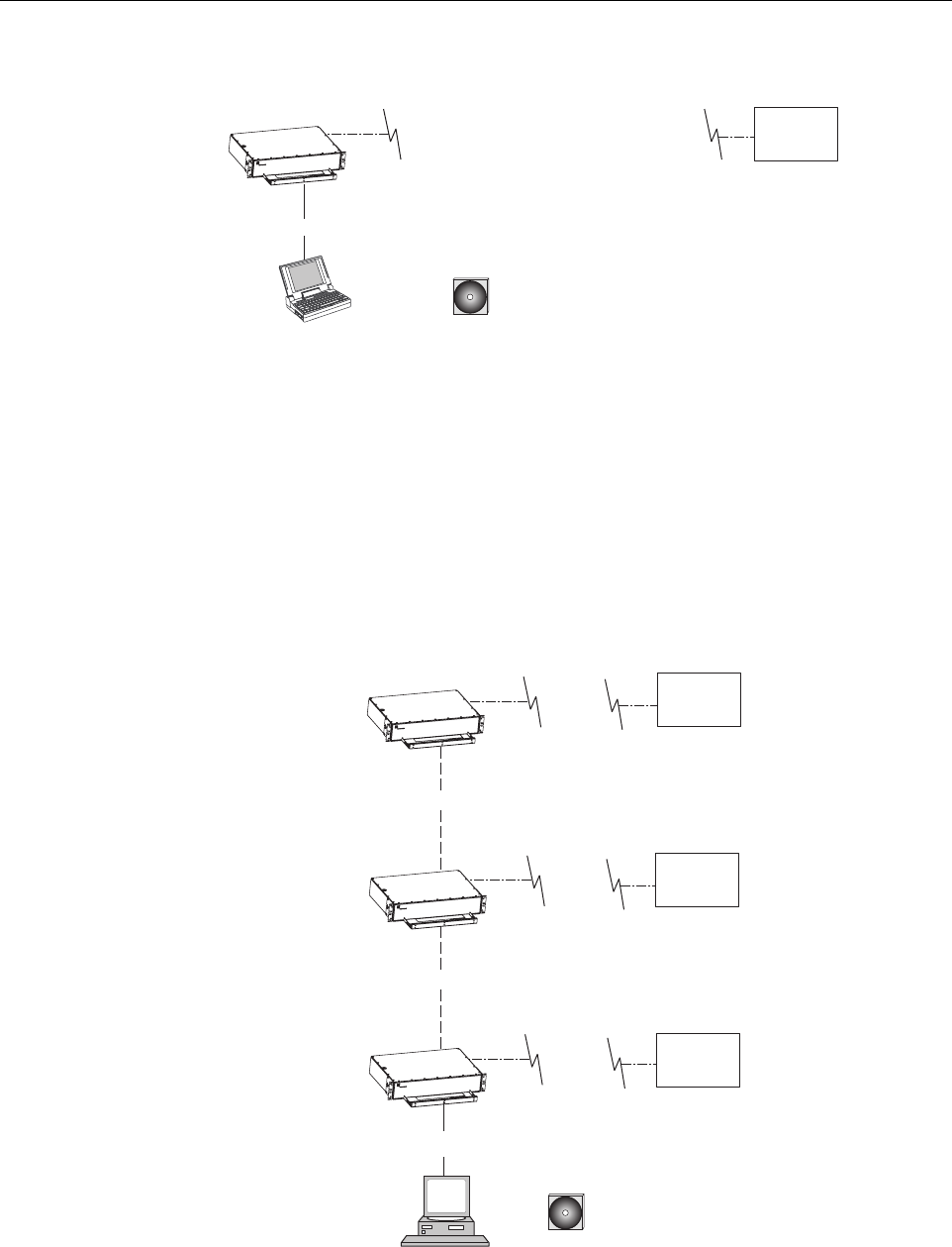
2.4 Local Management Interface
Communications with an individual Digivance system is supported through a local management
interface capability as shown in Figure 1-3. A local management interface requires a PC-type
computer loaded with the Digivance Element Management System (EMS) software. EMS
provides the various control and monitoring functions required to locally manage a Digivance
system. The EMS computer connects directly to the HU through the computer’s RS-232 port.
Operation is implemented through the EMS Graphical User Interface (GUI). The GUI consists
of a series of screens from which the user selects the desired option or function. An RS-232
service port is provided on the HU for connecting the EMS computer.
20856-A
HOST UNIT
RF
ENHANCED
BASE
TRANSCEIVER
STATION
FORWARD
PATHS
REVERSE
PATHS
ADCP-75-187 • Issue 3 • September 2006 • Section 1: OVERVIEW
Page 1-4
© 2006, ADC Telecommunications, Inc.
Figure 1-3. Local Management of a Single Digivance System
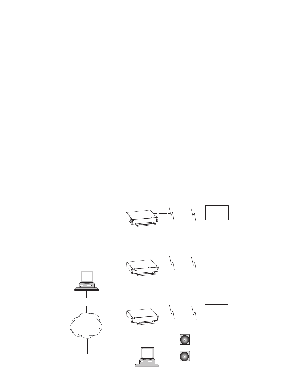
An EMS computer may be used to locally manage a networked group of multiple Digivance
systems as shown in Figure 1-4. A Controller Area Network (CAN) port is provided on each
HU. Up to twenty-four HU’s may be linked together through the CAN interface and controlled
by the same EMS computer. All the networked HU’s and the associated RU’s may be managed
by connecting the EMS computer to one HU. The EMS computer provides an RS-232 port (#1)
to support the interface with the networked HU’s.
Figure 1-4. Local Management of Networked Digivance Systems
HOST UNIT
LAPTOP WITH EMS
(LOCAL INTERFACE)
20565-A
CD-ROM WITH DIGIVANCE
ELEMENT MANAGEMENT
SYSTEM (EMS) SOFTWARE
REMOTE
UNIT
RS-232
PC COMPUTER WITH EMS
(LOCAL INTERFACE WITH
MULTIPLE SYSTEMS)
HOST UNIT
HOST UNIT
HOST UNIT
RS-232
20857-A
CD-ROM WITH DIGIVANCE
ELEMENT MANAGEMENT
SYSTEM (EMS) SOFTWARE
CAN
CAN
REMOTE
UNIT
REMOTE
UNIT
REMOTE
UNIT
NOTE: THE MAXIMUM LENGTH
FOR THE RS-232 CABLE IS 75 FEET
NOTE: THE SUM MAXIMUM
LENGTH FOR THE CAN BUS
CABLES IS 75 FEET
ADCP-75-187 • Issue 3 • September 2006 • Section 1: OVERVIEW
Page 1-5
© 2006, ADC Telecommunications, Inc.
2.5 Network Operations Center Interface
Communications between a Network Operations Center (NOC) and a networked group of
multiple Digivance systems is supported by a NOC interface capability as shown in Figure 1-5.
To support the NOC interface, a PC-type computer loaded with the Digivance Element
Management System (EMS) software is required. EMS provides the various control and
monitoring functions required to remotely manage multiple Digivance systems through the
NOC interface.
A Controller Area Network (CAN) port is provided on each HU. Up to twenty-four HU’s may
be linked together through the CAN interface and controlled by the same EMS computer. All
the networked HU’s and the associated RU’s may be managed by connecting the EMS computer
to one HU. The EMS computer provides an RS-232 port (#1) to support the interface with the
networked HU’s.
The NOC can be linked to the EMS computer through a T1 system, DS0 with RS232
conversion, or some other medium. The EMS computer provides an RS-232 ASCII interface
port (#2) to support the interface with the NOC.
At the NOC, control and monitoring of the networked Digivance systems is implemented
through a Network Element Manager (NEM) interface which requires only a VT100 terminal/
emulator for operation. The NEM interface language consists of simple ASCII text strings. All
communications are input as either SET or GET commands which result in ASCII text string
responses from the specified system or systems.
Figure 1-5. Remote Management of Networked Digivance Systems Through NOC Interface
PC COMPUTER WITH
EMS SOFTWARE
HOST UNIT
HOST UNIT
HOST UNIT
RS-232
20858-A
CD-ROM WITH EMS
SOFTWARE
CAN
CAN
NETWORK
OPERATIONS
CENTER
(REMOTE
INTERFACE)
RS-232
ASCII
T1, DS0
WITH RS232
CONVERSION,
OR OTHER
MEDIUM
REMOTE
UNIT
REMOTE
UNIT
REMOTE
UNIT
ADCP-75-187 • Issue 3 • September 2006 • Section 1: OVERVIEW
Page 1-6
© 2006, ADC Telecommunications, Inc.
2.6 SNMP Interface
Communications between an external Simple Network Management Protocol (SNMP) Manager
and a networked group of multiple Digivance systems is supported by an SNMP interface
capability as shown in Figure 1-6. To support the SNMP interface, a PC-type computer loaded
with both the Digivance Element Management System (EMS) software and the SNMP Proxy
Agent software is required. The EMS and SNMP Proxy Agent software plus the associated
Management Information Base (MIB) provide the various control (Set) monitoring (Get) and
trap functions required to remotely manage multiple Digivance systems using an SNMP
Manager.
A Controller Area Network (CAN) port is provided on each HU. Up to twenty-four HU’s may
be linked together through the CAN interface and controlled by the same EMS computer. All
the networked HU’s and the associated RU’s may be managed by connecting the EMS computer
to one HU. The EMS computer provides an RS-232 port (#1) to support the interface with the
networked HU’s.
The SNMP Manager may be linked with the EMS computer through a Local Area Network
(LAN). The EMS computer provides an Ethernet port to support the interface with the LAN.
The SNMP Proxy Agent supports two versions of the SNMP protocol: SNMPv1 and SNMPv2c.
A facility to Register/Unregister an SNMP Manager for receiving traps is also supported by the
SNMP Proxy Agent. The SNMP Manager is an option and must be ordered separately from
the EMS software.
Figure 1-6. Remote Management of Networked Digivance Systems Through SNMP Manager
PC COMPUTER WITH EMS
AND SNMP PROXY AGENT
HOST UNIT
HOST UNIT
HOST UNIT
RS-232
20859-A
CD-ROM WITH EMS
SOFTWARE
CD-ROM WITH SNMP
PROXY AGENT SOFTWARE
CAN
CAN
LOCAL
AREA
NETWORK
ETHERNET
NETWORK
SNMP
MANAGER
ETHERNET
REMOTE
UNIT
REMOTE
UNIT
REMOTE
UNIT
ADCP-75-187 • Issue 3 • September 2006 • Section 1: OVERVIEW
Page 1-7
© 2006, ADC Telecommunications, Inc.
3 SYSTEM FUNCTIONS AND FEATURES
This section describes various system level functions and features of the Digivance system.
3.1 Fiber Optic Transport
In a typical Digivance LRCS system, the HU is connected to the RU over two single-mode
optical fibers. One fiber is used to transport the forward path optical signal. The other fiber is
used to transport the reverse path optical signal. Because the optical signal is digital, the input
and output RF signal levels at the HU or the RU are not dependent on the level of the optical
signal or the length of the optical fiber. A diagram of the fiber optic transport system for a
typical Digivance LRCS system is shown in Figure 1-7.
Figure 1-7. LRCS System Fiber Optic Transport - Typical
The maximum length of the optical links is dependent on the loss specifications of the optical
fiber, the losses imposed by the various connectors and splices, and the RF modulation protocol
response timing limitations. The basic system provides an optical budget of 25 dB (typical)
when used with 9/125 single-mode fiber.
In SCS applications, the forward path and reverse path optical signals from an HU/RU pair are
combined onto a single optical fiber. This is accomplished by using a passive bi-directional
Wavelength Division Multiplexer (WDM) system. The optical wavelengths used in the
Digivance system are 1550 nm for the forward path and 1310 nm for the reverse path. Because
different wavelengths are used for the forward and reverse paths, both signals can be combined
on a single optical fiber. A WDM module (accessory) is installed with the HU at the host site
The SCS RU, which is equipped with an internally mounted WDM, is installed at the remote
site as shown in Figure 1-8.
Figure 1-8. SCS System Fiber Optic Transport with Wavelength Division Multiplexer
HOST UNIT
18526-A
REMOTE
UNIT
FORWARD PATH
REVERSE PATH
FIBER OPTIC
LINK
20721-A
HOST UNIT
REMOTE
UNIT
FORWARD AND
REVERSE PATH
WDM WDM
FIBER OPTIC LINK

ADCP-75-187 • Issue 3 • September 2006 • Section 1: OVERVIEW
Page 1-8
© 2006, ADC Telecommunications, Inc.
3.2 Control and Monitoring Software
The EMS software and the SNMP Proxy Agent software provide control and monitoring
functions for the Digivance system through the local, NOC, and SNMP interfaces. The EMS
software package supports the local and NOC interfaces but does not include the SNMP Proxy
Agent software which must be ordered separately. Both the EMS and the SNMP Proxy Agent
software are required to support the SNMP interface. All software files are provided on CD-
ROM’s. Software installation consists of copying the software files from the CD-ROM’s to a
designated directory on the hard-drive of the EMS computer.
The EMS software provides the capability to provision and configure the Digivance system for
operation. This includes selecting a site name, setting alarm thresholds, and setting forward and
reverse path RF gain adjustments. The EMS software also provides the capability to get alarm
messages (individual or summary), obtain data measurements, and to upgrade the HU/RU
system software. All control and monitor functions (except software upgrade which is not
supported by the NOC/NEM and SNMP interfaces and HU/RU pair site number assignment
which is not supported by the SNMP interface) may be implemented using the NOC/NEM
interface, the SNMP interface, or the EMS software GUI.
3.3 Fault Detection and Alarm Reporting
LED indicators are provided on the front panel of the HU and on the underside of the RU to
indicate if the system is normal or if a fault is detected. In addition, normally open and normally
closed alarm contacts (for both major and minor alarms) are provided at the HU for connection
to a customer-provided external alarm system. All alarms can also be accessed through the
NOC/NEM interface, SNMP manager, or the EMS software GUI.
3.4 Powering
The HU is powered by ±24 or ±48 VDC and must be hard-wired to a local DC power source
through a fuse panel. A screw-down terminal strip is provided on the rear side of the HU for the
power connections.
The RU is powered by 90 to 265 VAC (nominal 120 or 240 VAC), 47 to 63 Hz power. On an
optional basis, the RU may be powered by 60 to 89 VAC, 47 to 63 Hz power. A connector is
provided on the underside of the RU for the AC power connections. A 3-wire AC power cable
rated for outdoor use is included with the RU. The stub end of the cable must be hard-wired to
the AC power source.
3.5 Equipment Mounting and Location
The HU consists of a rack-mountable chassis assembly that is designed for mounting in a non-
condensing indoor environment such as inside a wiring closet or within an environmentally-
controlled cabinet. The HU is usually installed within 20 feet of the EBTS and may be mounted
in either a 19- or 23-inch, WECO or EIA, equipment rack.
The RU consists of a sealed aluminum enclosure designed for mounting in either an indoor or
outdoor environment. The RU may be mounted from a pole or the exterior side of a building
with the standard mounting bracket or from a strand with an accessory bracket.

ADCP-75-187 • Issue 3 • September 2006 • Section 1: OVERVIEW
Page 1-9
© 2006, ADC Telecommunications, Inc.
4 DUAL-BAND REMOTE UNIT SCS SYSTEMS
Sections 1 through 3 described the functions and features of a typical SCS system equipped with
one HU and the single-band RU. Each single-band RU is equipped with the electronics to
support one frequency band. If it is necessary to support two frequency bands (such as 800/900
MHz SMR and 1900 MHz) at the same remote location, a dual-band RU can be deployed. A
dual-band RU provides the electronic and optical functionality of two single-band RU’s except
that all the electronic and optical components are housed within a single enclosure.
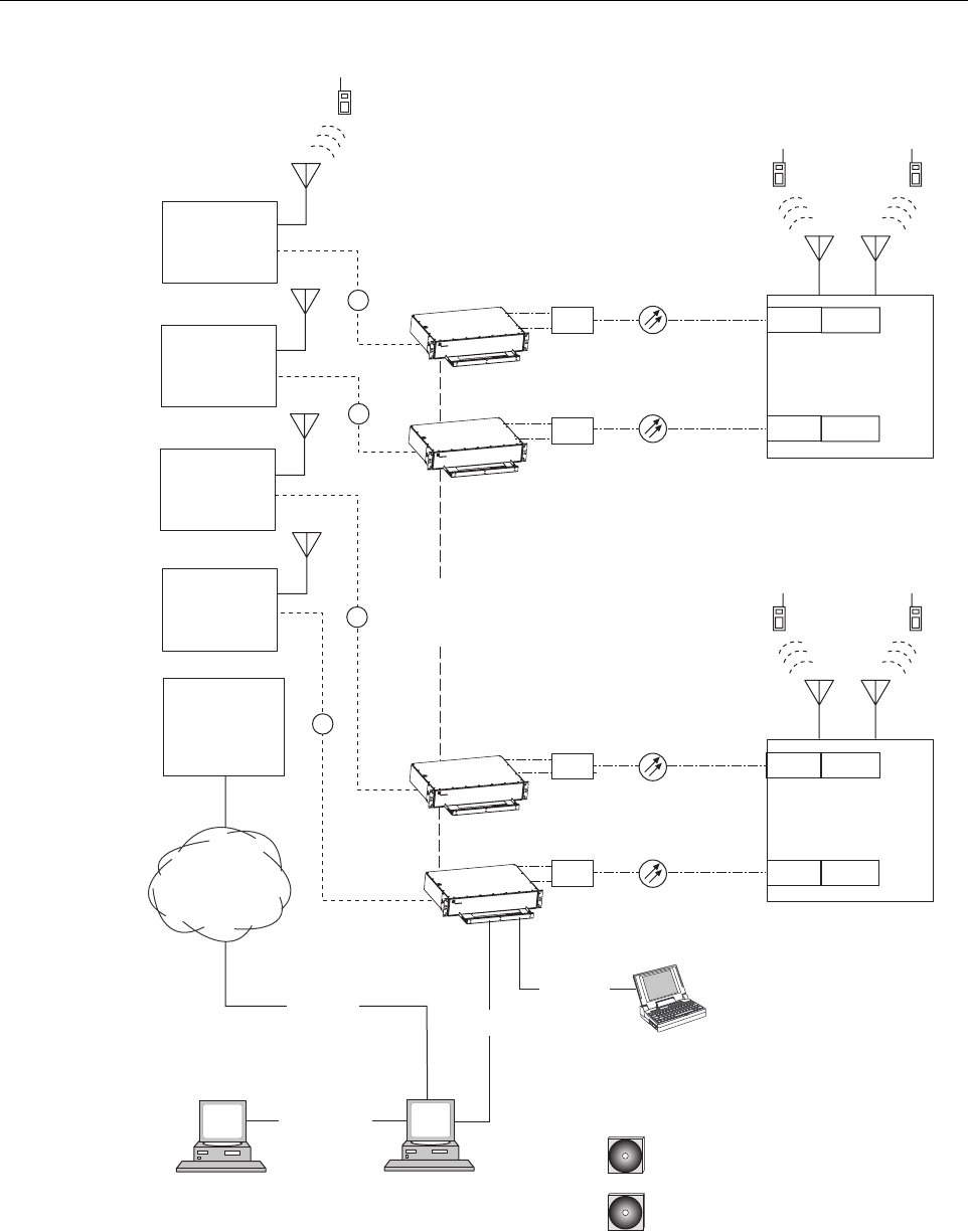
A dual-band SCS system consists of two standard host units and a dual-band RU that are linked
together over two optical fibers. At the hub site, each HU is connected to a separate EBTS
facility. The dual-band RU supports the frequency bands (such as 800/900 MHz SMR and 1900
MHz) associated with the two connected HU’s. Each HU and the corresponding RU electronics
function independently of each other and may be managed separately using the same element
management system (EMS). Figure 1-9 shows a typical SCS system equipped with a dual-band
RU. One fiber is used to transport the forward/reverse path optical signals for one SCS system.
The other fiber is used to transport the forward/reverse path optical signals for the other SCS
system.
ADCP-75-187 • Issue 3 • September 2006 • Section 1: OVERVIEW
Page 1-10
© 2006, ADC Telecommunications, Inc.
Figure 1-9. SCS System With Dual-Band Remote Units Overview Diagram
PC COMPUTER WITH EMS
AND SNMP PROXY AGENT
(PERMANENT CONNECTION)
HOST UNIT 1
HOST UNIT 2
HOST UNIT A
HOST UNIT B
NETWORK
OPERATIONS
CENTER
PC COMPUTER WITH EMS
(TEMPORARY CONNECTION)
T1, DS0
WITH RS232
CONVERSION,
OR OTHER
MEDIUM
RS-232
ASCII RS-232
20628-A
CD-ROM WITH EMS
SOFTWARE
RF
RS-232
NETWORK SNMP
MANAGER
CD-ROM WITH SNMP PROXY
AGENT SOFTWARE
ETHERNET
LAN
DUAL-BAND
REMOTE UNIT
DUAL-BAND
REMOTE UNIT
CONTROLLER
AREA
NETWORK
BAND 1
800/900 MHZ SMR
BAND A
800/900 MHZ SMR
BAND 2
1900 MHZ
BAND B
1900 MHZ
BASE STATION
ANTENNA
ENHANCED
BASE
TRANSCEIVER
STATION 1
ENHANCED
BASE
TRANSCEIVER
STATION 2
ENHANCED
BASE
TRANSCEIVER
STATION B
ENHANCED
BASE
TRANSCEIVER
STATION A
RF
RF
RF
UNIT 1
UNIT 2
UNIT A
UNIT B
WDM
WDM
WDM
WDM
WDM
WDM
WDM
WDM

ADCP-75-187 • Issue 3 • September 2006 • Section 2: DESCRIPTION
Page 2-1
© 2006, ADC Telecommunications, Inc.
SECTION 2: DESCRIPTION
1 INTRODUCTION. . . . . . . . . . . . . . . . . . . . . . . . . . . . . . . . . . . . . . . . . . . . . . . . . . . . . . . . . . . . . . . . . . . . . . . .2-2
2 HOST UNIT . . . . . . . . . . . . . . . . . . . . . . . . . . . . . . . . . . . . . . . . . . . . . . . . . . . . . . . . . . . . . . . . . . . . . . . . . . .2-2
2.1 Primary Components . . . . . . . . . . . . . . . . . . . . . . . . . . . . . . . . . . . . . . . . . . . . . . . . . . . . . . . . . . . . . .2-2
2.2 Mounting . . . . . . . . . . . . . . . . . . . . . . . . . . . . . . . . . . . . . . . . . . . . . . . . . . . . . . . . . . . . . . . . . . . . . .2-2
2.3 Fault Detection and Alarm Reporting . . . . . . . . . . . . . . . . . . . . . . . . . . . . . . . . . . . . . . . . . . . . . . . . . . .2-3
2.4 RF Signal Connections . . . . . . . . . . . . . . . . . . . . . . . . . . . . . . . . . . . . . . . . . . . . . . . . . . . . . . . . . . . . .2-4
2.5 RF Signal Level Adjustments. . . . . . . . . . . . . . . . . . . . . . . . . . . . . . . . . . . . . . . . . . . . . . . . . . . . . . . . .2-4
2.6 Propagation Delay . . . . . . . . . . . . . . . . . . . . . . . . . . . . . . . . . . . . . . . . . . . . . . . . . . . . . . . . . . . . . . . .2-4
2.7 Optical Connection . . . . . . . . . . . . . . . . . . . . . . . . . . . . . . . . . . . . . . . . . . . . . . . . . . . . . . . . . . . . . . .2-4
2.8 Controller Area Network Interface Connection . . . . . . . . . . . . . . . . . . . . . . . . . . . . . . . . . . . . . . . . . . . . .2-5
2.9 Service Interface Connection. . . . . . . . . . . . . . . . . . . . . . . . . . . . . . . . . . . . . . . . . . . . . . . . . . . . . . . . .2-5
2.10 Powering . . . . . . . . . . . . . . . . . . . . . . . . . . . . . . . . . . . . . . . . . . . . . . . . . . . . . . . . . . . . . . . . . . . . . .2-5
2.11 Cooling . . . . . . . . . . . . . . . . . . . . . . . . . . . . . . . . . . . . . . . . . . . . . . . . . . . . . . . . . . . . . . . . . . . . . . .2-5
2.12 User Interface . . . . . . . . . . . . . . . . . . . . . . . . . . . . . . . . . . . . . . . . . . . . . . . . . . . . . . . . . . . . . . . . . . .2-5
3 REMOTE UNIT. . . . . . . . . . . . . . . . . . . . . . . . . . . . . . . . . . . . . . . . . . . . . . . . . . . . . . . . . . . . . . . . . . . . . . . . .2-9
3.1 Primary Components . . . . . . . . . . . . . . . . . . . . . . . . . . . . . . . . . . . . . . . . . . . . . . . . . . . . . . . . . . . . . .2-9
3.2 Mounting . . . . . . . . . . . . . . . . . . . . . . . . . . . . . . . . . . . . . . . . . . . . . . . . . . . . . . . . . . . . . . . . . . . . . 2-10
3.3 Fault Detection and Alarm Reporting . . . . . . . . . . . . . . . . . . . . . . . . . . . . . . . . . . . . . . . . . . . . . . . . . . 2-10
3.4 Antenna Cable Connection . . . . . . . . . . . . . . . . . . . . . . . . . . . . . . . . . . . . . . . . . . . . . . . . . . . . . . . . . 2-11
3.5 RF Signal Level Adjustment . . . . . . . . . . . . . . . . . . . . . . . . . . . . . . . . . . . . . . . . . . . . . . . . . . . . . . . . 2-11
3.6 Optical Connection . . . . . . . . . . . . . . . . . . . . . . . . . . . . . . . . . . . . . . . . . . . . . . . . . . . . . . . . . . . . . . 2-11
3.7 Powering . . . . . . . . . . . . . . . . . . . . . . . . . . . . . . . . . . . . . . . . . . . . . . . . . . . . . . . . . . . . . . . . . . . . . 2-11
3.8 Grounding . . . . . . . . . . . . . . . . . . . . . . . . . . . . . . . . . . . . . . . . . . . . . . . . . . . . . . . . . . . . . . . . . . . . 2-12
3.9 Cooling . . . . . . . . . . . . . . . . . . . . . . . . . . . . . . . . . . . . . . . . . . . . . . . . . . . . . . . . . . . . . . . . . . . . . . 2-12
3.10 User Interface . . . . . . . . . . . . . . . . . . . . . . . . . . . . . . . . . . . . . . . . . . . . . . . . . . . . . . . . . . . . . . . . . . 2-12
4 ACCESSORY ITEMS . . . . . . . . . . . . . . . . . . . . . . . . . . . . . . . . . . . . . . . . . . . . . . . . . . . . . . . . . . . . . . . . . . . . 2-14
4.1 Strand Mount Kit for RU . . . . . . . . . . . . . . . . . . . . . . . . . . . . . . . . . . . . . . . . . . . . . . . . . . . . . . . . . . . 2-14
4.2 Lightning Protector for RU . . . . . . . . . . . . . . . . . . . . . . . . . . . . . . . . . . . . . . . . . . . . . . . . . . . . . . . . . 2-14
4.3 Solar Shields . . . . . . . . . . . . . . . . . . . . . . . . . . . . . . . . . . . . . . . . . . . . . . . . . . . . . . . . . . . . . . . . . . 2-15
5 DIGIVANCE ELEMENT MANAGEMENT SYSTEM. . . . . . . . . . . . . . . . . . . . . . . . . . . . . . . . . . . . . . . . . . . . . . . . . . 2-15
5.1 Digivance EMS Primary Components . . . . . . . . . . . . . . . . . . . . . . . . . . . . . . . . . . . . . . . . . . . . . . . . . . 2-15
5.2 Software Installation . . . . . . . . . . . . . . . . . . . . . . . . . . . . . . . . . . . . . . . . . . . . . . . . . . . . . . . . . . . . . 2-16
5.3 Computer Operation. . . . . . . . . . . . . . . . . . . . . . . . . . . . . . . . . . . . . . . . . . . . . . . . . . . . . . . . . . . . . . 2-16
5.4 Digivance EMS Computer Interface Connections . . . . . . . . . . . . . . . . . . . . . . . . . . . . . . . . . . . . . . . . . . 2-16
5.5 Digivance Software User Interfaces . . . . . . . . . . . . . . . . . . . . . . . . . . . . . . . . . . . . . . . . . . . . . . . . . . . 2-17
6 SPECIFICATIONS . . . . . . . . . . . . . . . . . . . . . . . . . . . . . . . . . . . . . . . . . . . . . . . . . . . . . . . . . . . . . . . . . . . . . . 2-19
_________________________________________________________________________________________________________
Content Page

ADCP-75-187 • Issue 3 • September 2006 • Section 2: DESCRIPTION
Page 2-2
© 2006, ADC Telecommunications, Inc.
1 INTRODUCTION
This section describes the basic components of a typical Digivance SCS system including the
Host Unit (HU), Remote Unit (RU), element management system, and accessories. The system
specifications are provided in a table at the end of this section.
2 HOST UNIT
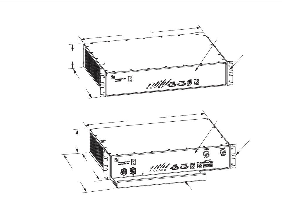
Two versions of the HU are available. The rear access HU, shown in Figure 2-1, is used with
800/900 MHz SMR systems. The front access HU, also shown in Figure 2-1, is used with 800
and 1900 MHz systems. Connection points for the RF, optical, and alarm cables are provided on
the rear side of the rear access HU and on the front side of the front access HU. Both HU
versions provide the following basic functions:
• Provides a limited adjustable RF interface with the BTS.
• Provides a fiber optic interface with the RU.
• Digitizes the two forward path composite RF signals.
• Converts the two digitized forward path RF signals to a digital optical signal.
• Converts the digitized reverse path optical signal to two digitized RF signals.
• Converts the two digitized reverse path RF signals to two composite RF signals.
• Sends alarm information to an external alarm system through relay contact closures
• Provides an RS-232 interface for connecting the EMS computer.
• Provides a CAN interface for networking multiple HUs.
2.1 Primary Components
The HU consists of an electronic circuit board assembly and a fan assembly that are mounted
within a powder-paint coated sheet metal enclosure. The enclosure provides a mounting point
for the circuit board and fan assemblies and controls RF emissions. The only user-replaceable
component is the fan assembly. The HU is designed for use within a non-condensing indoor
environment such as inside a wiring closet or cabinet. The front access HU is also equipped
with a front cable management tray and vertical cable guides.
2.2 Mounting
The HU is intended for rack-mount applications. A pair of reversible mounting brackets is
provided that allow the HU to be mounted in either a 19-inch or 23-inch EIA or WECO
equipment rack. When the rear access HU is installed, the front panel of the HU is flush with the
front of the rack. When the front access HU is installed, the front panel of the HU is flush with
the front of the rack and the cable management tray extends 3.9 inches (99 mm) beyond the
front panel. Screws are provided for securing the HU to the equipment rack.
ADCP-75-187 • Issue 3 • September 2006 • Section 2: DESCRIPTION
Page 2-3
© 2006, ADC Telecommunications, Inc.
Figure 2-1. Front View of Front and Rear Access Host Units
2.3 Fault Detection and Alarm Reporting
The HU detects and reports various internal and external faults including host unit fault, optical
fault, power fault, temperature fault, and RF fault. Various front panel Light Emitting Diode
(LED) indicators turn from green to red or yellow if a fault is detected. A set of alarm contacts
(normally open and normally closed) are provided for reporting an alarm to an external alarm
system when a fault is detected. Both major alarm (system operation seriously affected) and
minor alarm (system operation not affected or only slightly degraded) contacts are provided.
Fault and alarm information may also be accessed locally through the EMS software GUI or
remotely through the NOC/NEM interface or SNMP interface. An alarm history file is
maintained by the EMS software so that a record is kept of all alarms as they occur. This is
useful when an alarm is reported and cleared before the reason for the alarm can be determined.
The status of the HU, the alarm state (major or minor), and other alarm information is
summarized and reported over the service interface, the CAN interface, and the optical interface
to the RU. In addition, the status of the RU is transmitted to the HU over the optical interface
and reported over the service interface and the CAN interface.
17.1 INCHES
(433 mm)
3.5 INCHES
(88 mm)
12.2 INCHES
(311 mm)
FRONT PANEL
MOUNTING
BRACKET
(BOTH SIDES)
REAR ACCESS HOST UNIT
FRONT ACCESS HOST UNIT
20666-A
17.2 INCHES
(437 mm)
3.5 INCHES
(89 mm)
11.4 INCHES
(290 mm)
15.3 INCHES
(389 mm)
FRONT PANEL
CABLE MANAGEMENT
TRAY
MOUNTING
BRACKET
(BOTH SIDES)

ADCP-75-187 • Issue 3 • September 2006 • Section 2: DESCRIPTION
Page 2-4
© 2006, ADC Telecommunications, Inc.
2.4 RF Signal Connections
The RF signal connections between the rear access HU and the EBTS are supported through
four N-type female connectors. Two connectors are used for the forward path RF signals and
two connectors are used for the reverse path RF signals.
The RF signal connections between the front access HU and the EBTS are supported through
two N-type female connectors. One connector is used for the forward path RF signal and the
other connector is used for the reverse path RF signal.
In most installations, it is usually necessary to install external attenuators to support the RF
interface between the HU and the EBTS. The HU should be as close as possible to the EBTS to
minimize coaxial cable losses.
2.5 RF Signal Level Adjustments
The HU is equipped with several attenuators for adjusting the signal levels of the forward and
reverse path RF signals. The attenuators provide an attenuation adjustment range of 0 to 31 dB
and can be set in 1 dB increments. The attenuators are software controlled and are adjusted
through the EMS software GUI, NOC/NEM interface, or SNMP interface.
The host forward path attenuators adjust the level of the input RF signal(s) to the HU. Using
the forward path attenuator, an input signal with a nominal composite signal level of –9 dBm to
–40 dBm can be adjusted to produce maximum power output. Additional external attenuation
is required if the input signal level is greater than –9 dBm.
The host reverse path attenuators adjust the level of the output RF signal(s) from the HU and
will add from –1 dB of gain (attenuator set to 31 dB) to +30 dB of gain (attenuator set to 0 dB)
to the RF output signal(s) at the HU.
2.6 Propagation Delay
The HU forward and reverse path propagation delays may be adjusted in 0.1 μsec increments
within a range of 0 to 63 μs. The propagation delay is software controlled and may be adjusted
through the EMS software GUI, NOC/NEM interface, or SNMP interface.
2.7 Optical Connection
Optical connections between the HU and the RU are supported through two optical ports
equipped with UPC/SC (flat) connectors. One port is used for the forward path optical signal
connection and the other port is used for the reverse path optical signal connection.
Note: The optimum composite RF input signal level for 800/900 MHz SMR systems is
–20 dBm.

ADCP-75-187 • Issue 3 • September 2006 • Section 2: DESCRIPTION
Page 2-5
© 2006, ADC Telecommunications, Inc.
2.8 Controller Area Network Interface Connection
Controller Area Network (CAN) interface connections between multiple HUs are supported by
a pair of RJ-45 jacks. One of the jacks is designated as the network IN port and the other jack is
designated as the network OUT port. The CAN interface allows up to 24 HUs to be connected
together (in daisy-chain fashion) and controlled through a single EMS computer.
2.9 Service Interface Connection
The service interface connection between the HU and the EMS computer is supported by a
single DB-9 female connector. The service connector provides an RS-232 DTE interface. When
multiple HUs are networked together, the supporting EMS computer may be connected to the
service connector of any one of the networked HUs.
2.10 Powering
The HU is powered by ± 21 to ± 60 VDC power (nominal ± 24 or ± 48 VDC). The power is fed to
the HU through a screw-down type terminal strip located on the rear side of the unit. Power to
the HU must be supplied through a fuse panel such as the PowerWorx GMT Series Fuse Panel
(available separately). The power circuit for each HU must be protected with a 3 Amp GMT
fuse. An On/Off switch is provided on the HU front panel.
2.11 Cooling
Continuous airflow for cooling is provided by dual fans mounted on the right side of the HU
housing. A minimum of 3 inches (76 mm) of clearance space must be provided on both the left
and right sides of the HU for air intake and exhaust. An alarm is generated if a high temperature
condition (>50º C/122º F) occurs. The fans may be field-replaced if either fan fails.
2.12 User Interface
The HU user interface consists of the various connectors, switches, terminals, and LEDs that are
provided on the HU front and rear panels. The rear access HU user interface points are
indicated in Figure 2-2 and described in Table 2-1. The front access HU user interface points
are indicated in Figure 2-3 and described in Table 2-2.
ADCP-75-187 • Issue 3 • September 2006 • Section 2: DESCRIPTION
Page 2-6
© 2006, ADC Telecommunications, Inc.
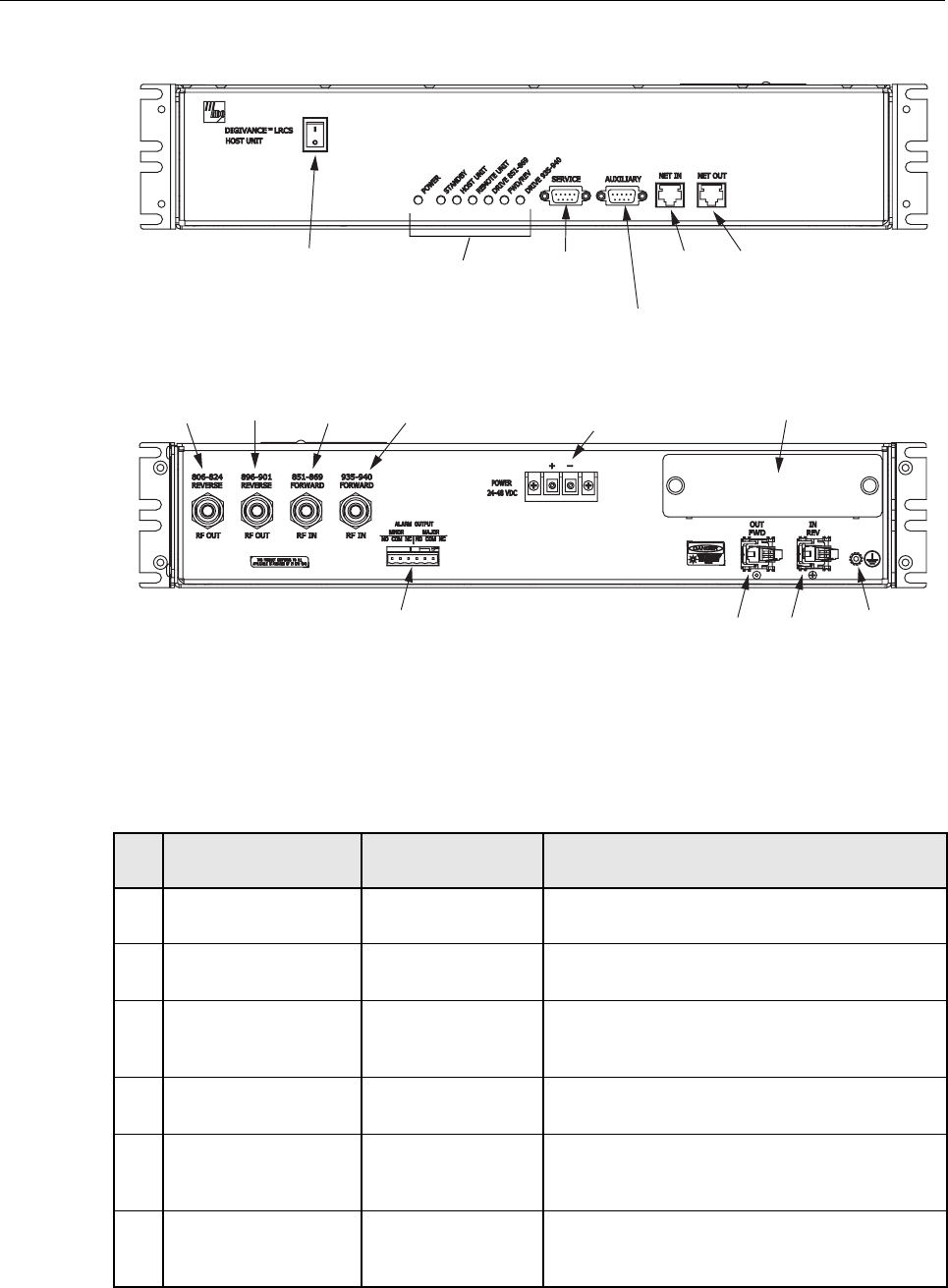
Figure 2-2. Rear Access Host Unit User Interface
Table 2-1. Host Unit User Interface
REF
NO
USER INTERFACE
DESIGNATION DEVICE FUNCTIONAL
DESCRIPTION
1 I/0 On/Off rocker
switch
Provides DC power on/off control.
2 POWER Multi-colored LED
(green/yellow)
Indicates if the HU is powered (green) or unpow-
ered (off). See Note.
3 STANDBY Multi-colored LED
(green/yellow/red)
Indicates if the system is in the Normal (off),
Standby (blinking green), Test (blinking red), or
Program Load (blinking yellow) state. See Note.
4 HOST UNIT Multi-colored LED
(green/yellow/red)
Indicates if the HU is normal (green), overheated
(yellow), or faulty (red). See Note.
5 REMOTE UNIT Multi-colored LED
(green/yellow/red)
Indicates if no alarms (green), a minor alarm
(yellow), or a major alarm (red) is reported by the
RU. See Note.
6 DRIVE 851–869 Multi-colored LED
(green/yellow/red)
Indicates if the level of the 851–869 MHz RF
input signal to the HU is normal (green), low
(yellow), or high (red). See Note.
(1) DC POWER
ON/OFF SWITCH
(21)
REV
(20)
FWD
(REFERENCE
ITEMS 2 - 8)
LED INDICATORS
(9) SERVICE
INTERFACE
CONNECTOR
(11) NET IN
CONNECTOR
(10) AUXILIARY
CONNECTOR
(12) NET OUT
CONNECTOR
(19) ALARM
OUTPUT CONNECTOR
(13) 806-824
REVERSE
(15) 851-869
FORWARD
(16) 935-940
FORWARD
(14) 896-901
REVERSE
20021-A
(17) DC POWER
TERMINAL STRIP
REAR VIEW
FRONT VIEW
(18) COVER PLATE
(22)
GROUNDING
STUD

ADCP-75-187 • Issue 3 • September 2006 • Section 2: DESCRIPTION
Page 2-7
© 2006, ADC Telecommunications, Inc.
7FWD/REV
(PORT 1/PORT 2)
Multi-colored LED
(green/red)
Indicates if the reverse/forward path optical sig-
nals from the RU/HU are normal (green), if no
signals are detected (red), or if excessive errors
are detected (red). See Note.
8 DRIVE 935–940 Multi-colored LED
(green/yellow/red)
Indicates if the level of the 935–940 MHz RF
input signal to the HU is normal (green), low
(yellow), or high (red). See Note.
9 SERVICE DB-9 connector
(female)
Connection point for the RS-232 service inter-
face cable.
10 AUXILIARY DB-9 connector
(female)
Connection point for the RS-232 auxiliary inter-
face cable. Not supported by SCS Remote Unit.
11 NET IN RJ-45 jack (female) Connection point for the CAN interface input
cable.
12 NET OUT RJ-45 jack (female) Connection point for the CAN interface output
cable.
13 806–824 REVERSE N-type female RF
coaxial connector
Output connection point for the 806–824 MHz
reverse path RF coaxial cable.
14 896–901 REVERSE N-type female RF
coaxial connector
Output connection point for the 896–901 MHz
reverse path RF coaxial cable.
15 851–869 FORWARD N-type female RF
coaxial connector
Input connection point for the 851–869 MHz for-
ward path RF coaxial cable.
16 935–940 FORWARD N-type female RF
coaxial connector
Input connection point for the 935–940 MHz for-
ward path RF coaxial cable.
17 POWER 24–48 VDC Screw-type terminal
strip
Connection point for the DC power wiring.
18 No designation Cover plate Covers the mounting slot for the wavelength divi-
sion multiplexer module.
19 ALARM OUTPUT Screw-type terminal
connector (14–26
AWG)
Connection point for an external alarm system.
Includes normally open (NO), normally closed
(NC), and common (COM) wiring connections.
20 FWD (PORT 1) UPC/SC connector
(flat single-mode)
Output connection point for the forward path
optical fiber.
21 REV (PORT 2) UPC/SC connector
(flat single-mode)
Input connection point for the reverse path opti-
cal fiber.
22 Chassis ground stud Connection point for a chassis grounding wire.
Note: A more detailed description of LED operation is provided in Section 4.
Table 2-1. Host Unit User Interface, continued
REF
NO
USER INTERFACE
DESIGNATION DEVICE FUNCTIONAL
DESCRIPTION
ADCP-75-187 • Issue 3 • September 2006 • Section 2: DESCRIPTION
Page 2-8
© 2006, ADC Telecommunications, Inc.
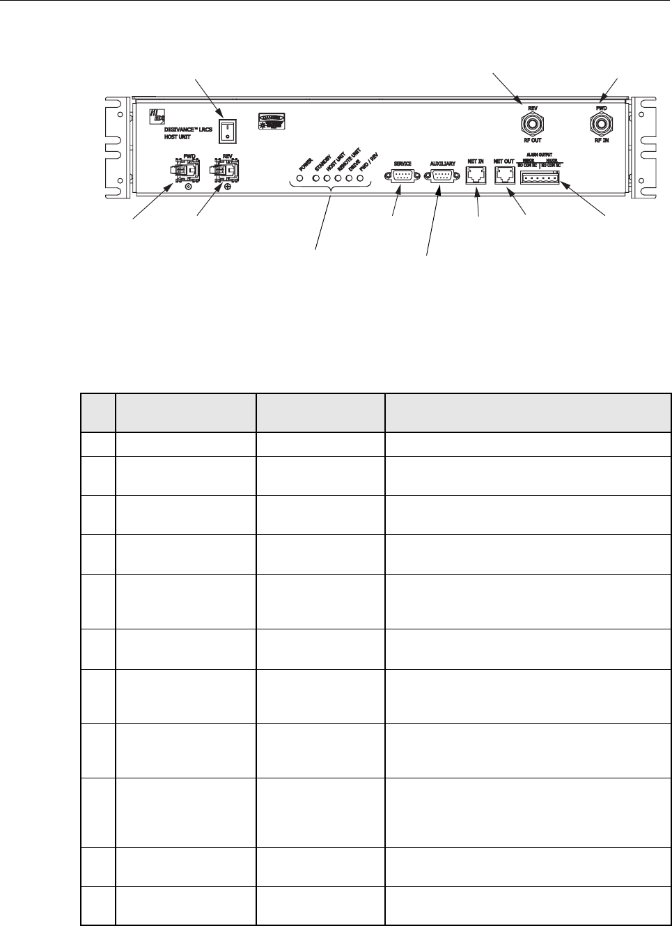
Figure 2-3. Front Access Host Unit User Interface
Table 2-2. Host Unit User Interface
REF
NO
USER INTERFACE
DESIGNATION DEVICE FUNCTIONAL
DESCRIPTION
1I/0 On/Off rocker switch Provides DC power on/off control.
2 FWD SC connector
(single-mode)
Output connection point for the forward path
optical fiber.
3 REV SC connector
(single-mode)
Input connection point for the reverse path pri-
mary optical fiber.
4 POWER Multi-colored LED
(green/yellow)
Indicates if the HU is powered (green) or unpow-
ered (off). See Note.
5 STANDBY Multi-colored LED
(green/yellow/red)
Indicates if the system is in the Normal (off),
Standby (blinking green), Test (blinking red), or
Program Load (blinking yellow) state. See Note.
6 HOST UNIT Multi-colored LED
(green/yellow/red)
Indicates if the HU is normal (green), overheated
(yellow), or faulty (red). See Note.
7 REMOTE UNIT Multi-colored LED
(green/yellow/red)
Indicates if no alarms (green), a minor alarm
(yellow), or a major alarm (red) is reported by the
RU. See Note.
8 DRIVE Multi-colored LED
(green/yellow/red)
Indicates if the level of the RF input signal to the
HU is normal (green), low (yellow), or high
(red). See Note.
9 FWD/REV Multi-colored LED
(green/red)
Indicates if the reverse path optical signals from
the STM are normal (green), if no signals are
detected (red), or if excessive errors are detected
(red). See Note.
10 SERVICE DB-9 connector
(female)
Connection point for the RS-232 service inter-
face cable.
11 AUXILIARY DB-9 connector
(female)
Not used with SCS systems.
(1) DC POWER
ON/OFF SWITCH
NOTE: SHOWN WITHOUT
CABLE MANAGEMENT TRAY
(2) PORT 1
OR FWD
CONNECTOR
(3) PORT 2
OR REV
CONNECTOR
(REFERENCE
ITEMS 4 - 9)
LED INDICATORS
(10) SERVICE
INTERFACE
CONNECTOR
(12) NET IN
CONNECTOR
(13) NET OUT
CONNECTOR
(14) ALARM
OUTPUT
CONNECTOR
(15) REVERSE
RF OUT
(16) FORWARD
RF IN
20667-A
(11) AUXILIARY INTERFACE
CONNECTOR
(NOT USED FOR SCS)

ADCP-75-187 • Issue 3 • September 2006 • Section 2: DESCRIPTION
Page 2-9
© 2006, ADC Telecommunications, Inc.
3 REMOTE UNIT
The RU is available in either a single-band or a dual-band version. Both versions of the RU
provide the following basic functions:
• Convert the digitized forward path optical signals to digitized RF signals.
• Convert the digitized forward path RF signals to composite RF signals.
• Digitize the reverse path composite RF signals.
• Convert the digitized reverse path RF signals to digitized optical signals.
• Provide an RF interface (antenna port) for the remote antenna(s).
• Provide an optical interface for the HU.
• Transport alarm, control, and monitoring information to the HU via the optical interface.
• Accept AC power input.
• Provide a visual indication of unit status
3.1 Primary Components
Depending on the version, the RU consists of either two or four electronic assemblies mounted
within an environmentally-sealed cast-aluminum enclosure. The Spectrum Transport Module
(STM) provides optical-to-RF and RF-to-optical conversion and digitizing functions; alarm,
control, and monitoring functions; power conversion functions; RF filtering and interface
functions. The Linear Power Amplifier (LPA) works in conjunction with the STM to amplify
12 NET IN RJ-45 jack (female) Connection point for the CAN interface input
cable.
13 NET OUT RJ-45 jack (female) Connection point for the CAN interface output
cable.
14 ALARM OUTPUT Screw-type terminal
connector (14–26
AWG)
Connection point for an external alarm system.
Includes normally open (NO), normally closed
(NC), and common (COM) wiring connections.
15 REV RF OUT N-type female RF
coaxial connector
Output connection point for the primary reverse
path RF coaxial cable.
16 FWD RF IN N-type female RF
coaxial connector
Input connection point for the forward path RF
coaxial cable.
POWER 24–48 VDC
(Rear side - not shown)
Screw-type terminal
strip
Connection point for the DC power wiring.
(Rear side - not shown)
Chassis ground stud Connection point for a chassis grounding wire.
Note: A more detailed description of LED operation is provided in Section 4.
Table 2-2. Host Unit User Interface, continued
REF
NO
USER INTERFACE
DESIGNATION DEVICE FUNCTIONAL
DESCRIPTION
ADCP-75-187 • Issue 3 • September 2006 • Section 2: DESCRIPTION
Page 2-10
© 2006, ADC Telecommunications, Inc.
the forward path RF signal. The aluminum enclosure provides a mounting point for the
electronic assemblies, controls RF emissions, seals out dirt and moisture, and provides passive
cooling. The electronic assemblies are not user replaceable or accessible. All connectors and
indicators are mounted on the bottom of the RU enclosure for easy access.
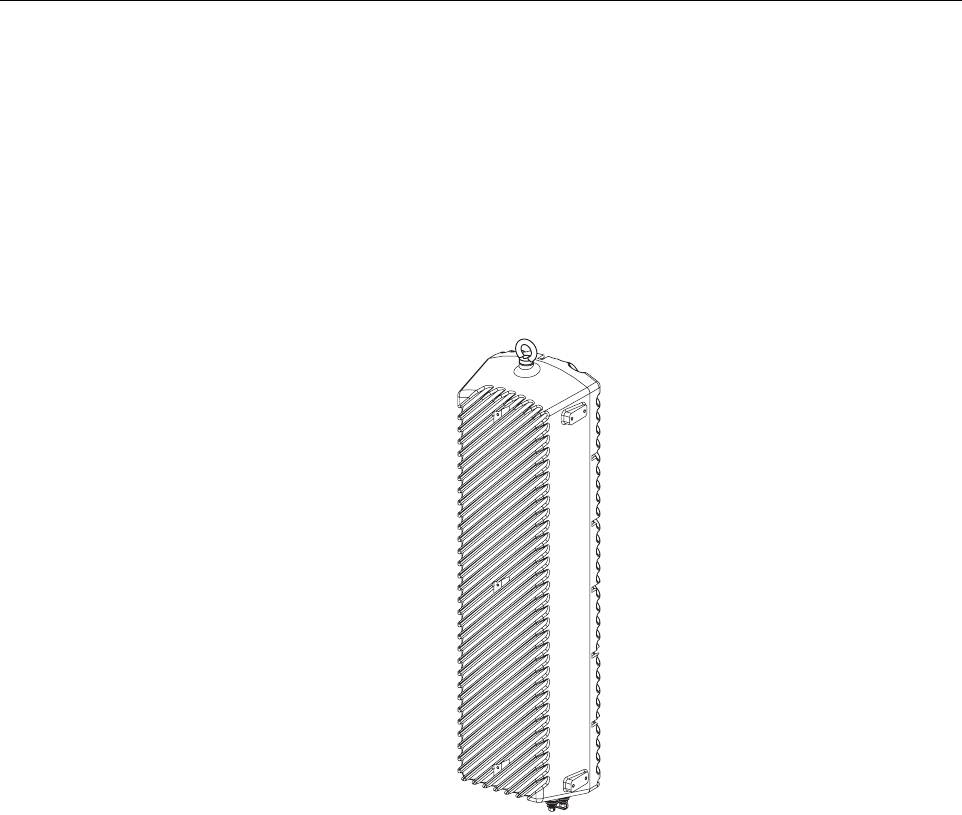
The single-band version of the RU consists of one STM and one LPA mounted within the same
enclosure. The dual-band version, shown in Figure 2-4, consists of two STM’s and two LPA’s
mounted within the same enclosure. The dual-band version makes it possible to support two
separate frequency bands with a single RU.
Figure 2-4. Dual-Band Remote Unit
3.2 Mounting
The RU may be mounted on a flat vertical surface (such as the side of a building), on a utility pole,
or from a horizontal cable or overhead support. A combination wall/pole mounting bracket is
provided with each unit. A separate strand-mount kit (accessory item) is available if it is necessary
to mount the RU from a cable. Inside-pole mounting and underground vault installations are also
possible. Contact the Wireless TAC (see Section 5) for additional information.
3.3 Fault Detection and Alarm Reporting
The RU detects and reports various faults including remote unit fault, optical fault, output power
fault, temperature fault, and power amplifier fault. A single bottom-mounted Light Emitting
Diode (LED) indicator turns from off to red if a major fault is detected. The status of the STM
and LPA, the alarm state, and other fault information is summarized and reported over the
optical interface to the HU. Fault and alarm information may be accessed at the HU through the
EMS software GUI or remotely through the NOC/NEM interface or SNMP interface.
20568-C

ADCP-75-187 • Issue 3 • September 2006 • Section 2: DESCRIPTION
Page 2-11
© 2006, ADC Telecommunications, Inc.
3.4 Antenna Cable Connection
The antenna cable connection between the RU and the antenna is supported through either one
(single-band RU) or two (dual-band RU) 50-ohm N-type female connectors. The antenna cable/
cables carry the forward and reverse path RF signals between each antenna and RU. An
externally-mounted lightning protector is available as an accessory. The antenna connector on
the lightning protector may be either an N-type female connector or a 7/16 mm DIN connector.
The RU enclosure must be properly grounded for the lighting protector to function properly. On
an optional basis, the dual-band RU may be equipped with one N-type connector (and internal
diplexor) to support operation with a single antenna.
3.5 RF Signal Level Adjustment
The RU is equipped with digital attenuators for adjusting the signal level of the forward path RF
output signals. The remote forward path attenuators adjust the level of the two output RF
signals at the RU antenna port and will add from 0 to 31 dB of attenuation to the output signal
level. The attenuator can be set in 1 dB increments. The attenuator is software controlled and is
adjusted through the EMS software GUI, the NOC/NEM interface, or SNMP interface.
3.6 Optical Connection
Fiber optic connections between the single-band RU and the associated HU are supported
through a single hardened optical port. All single-band RU’s are equipped with an internally
mounted Wavelength Division Multiplexer (WDM). This allows a single optical port to provide
the optical fiber connection for the combined forward and reverse path signals.
Fiber optic connections between the dual-band RU and the two associated HU’s (two HU’s are
required with a dual-band RU) are supported through two hardened optical ports. All dual-band
RU’s are equipped with two internally-mounted WDM’s. One port provides the optical fiber
connection for the combined forward and reverse path signals for HU #1. The other port provides
the optical fiber connection for the combined forward and reverse path signals for HU #2.
Each hardened optical port houses an SC adapter. A standard APC/SC type connector is
connected to the internal side of the adapter. The optical port accepts drop cables that are
terminated with APC/SC hardened connectors. The optical port is also compatible with OptiTap
connectors manufactured by Corning Incorporated.
3.7 Powering
The RU is powered by 90 to 265 VAC (nominal 120 or 240 VAC), 47 to 63 Hz power. On an
optional basis, the RU may be powered by 60 to 89 VAC, 47 to 63 Hz power. The power is
supplied through a 20-foot three-wire AC power cable that is provided with the RU. The power
cable connects to a mini 3-pin power connector mounted on the bottom of the RU enclosure.
The stub end of the cable must be hard-wired to the AC power source. The power cable is rated
for indoor or outdoor use and must not be routed through conduit. Accessory power cables are
also available separately in lengths of 40, 60, or 100 feet.

ADCP-75-187 • Issue 3 • September 2006 • Section 2: DESCRIPTION
Page 2-12
© 2006, ADC Telecommunications, Inc.
3.8 Grounding
A grounding terminal (hex socket capscrew and washer) is provided on the bottom of the
enclosure for connecting a grounding cable to the enclosure. A 1.5 meter #6 stranded copper
wire terminated with a ring terminal is provided with the RU for linking the enclosure to an
earth ground source.
3.9 Cooling
Passive cooling of the electronic assemblies is provided by conducting excess heat from the
electronic components to the aluminum enclosure. The heat is dissipated to the outside air by
radiation and convection air flow over the enclosure’s external cooling fins. An alarm is
generated if a high temperature condition occurs within the enclosure. If necessary, the RU may
be equipped with solar shields (accessory) that reduce the effect of solar loading on the
aluminum enclosure.
3.10 User Interface
The RU user interface consists of the connectors, grounding lug, and LED that are provided on
the bottom of the RU enclosure. The user interface points for the single-band RU are indicated
in Figure 2-5 and described in Table 2-3. The user interface points for the interim single-band
and the dual-band RU are indicated in Figure 2-6 and described in Table 2-4.
Figure 2-5. Single-Band Remote Unit User Interface
(1) OPTICAL PORT
(2) GROUNDING LUG
CONNECTION POINT
(4) N-TYPE CONNECTOR
FOR ANTENNA
(5) LED
INDICATOR
(3) AC POWER
CONNECTOR 20981-A
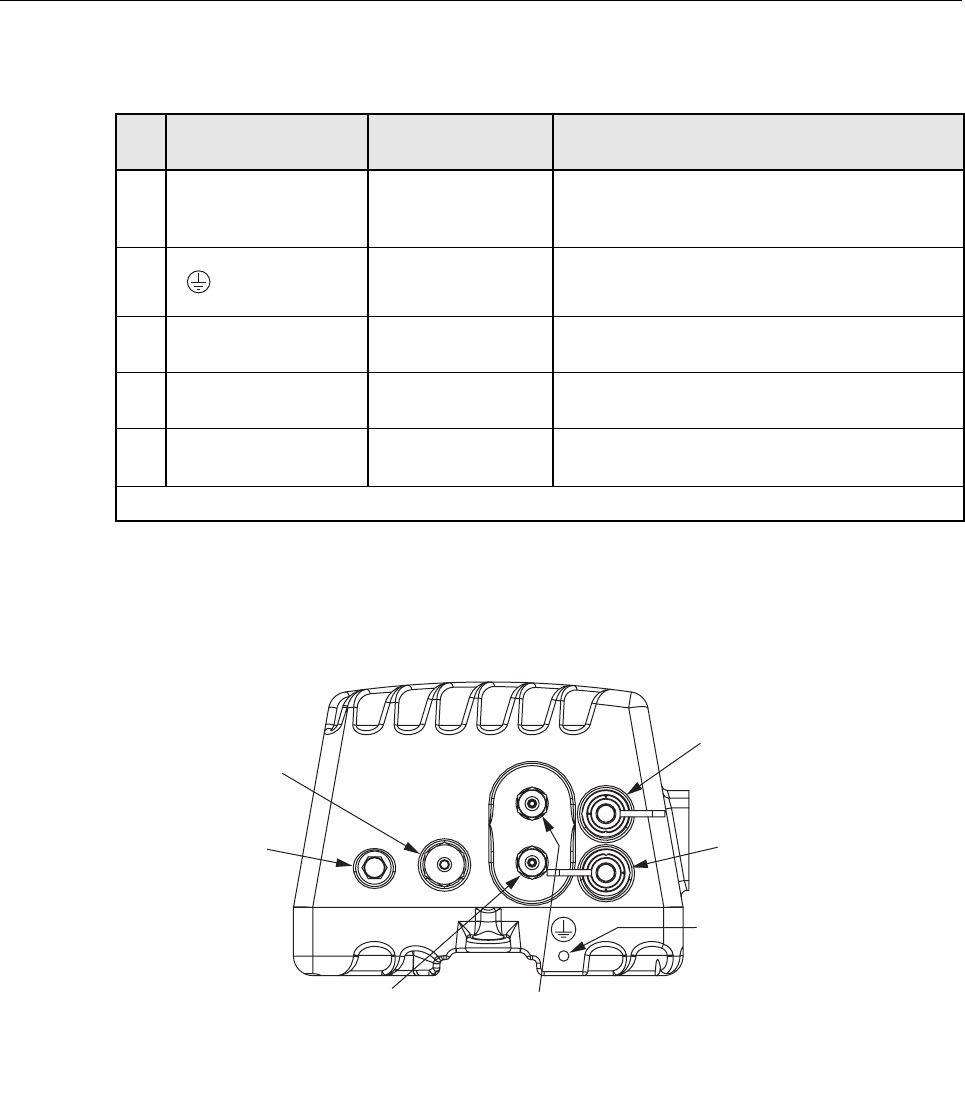
ADCP-75-187 • Issue 3 • September 2006 • Section 2: DESCRIPTION
Page 2-13
© 2006, ADC Telecommunications, Inc.
Figure 2-6. Interim Single-Band and Dual-Band Remote Unit User Interface
Table 2-3. Single-Band Remote Unit User Interface
REF
NO
USER INTERFACE
DESIGNATION DEVICE FUNCTIONAL
DESCRIPTION
1 BAND 1 APC/SC hardened
adapter
Input/output connection point for the combined
forward and reverse path optical fiber. The host
unit must be equipped with a WDM.
2 Threaded hole with
hex socket screw
Connection point for the grounding wire.
3 POWER Mini 3-wire AC
power connector
Connection point for the AC power cord.
4 ANT N-type female RF
coaxial connector
Connection point for the antenna cable.
5 No designation Red LED
(off/red)
Indicates if the RU is powered and normal (off)
or if a major fault is detected (red). See Note.
Note: A more detailed description of the LED operation is provided in Section 4.
20976-A
(1) BAND 1 OPTICAL PORT
(USED WITH INTERIM SINGLE-
BAND AND DUAL-BAND UNIT)
(2) BAND 2 OPTICAL PORT
(NOT USED WITH INTERIM
SINGLE-BAND UNIT)
(3) GROUNDING LUG
CONNECTION POINT
(5) BAND 2 ANTENNA
CONNECTOR (N-TYPE)
(4) BAND 1 ANTENNA
CONNECTOR (N-TYPE)
(6) LED
INDICATOR
(7) AC POWER
CONNECTOR
NOTE: THE STANDARD REMOTE UNIT IS EQUIPPED WITH
TWO ANTENNA CONNECTORS. AS AN OPTION, THE REMOTE
UNIT CAN BE EQUIPPED WITH ONE ANTENNA CONNECTOR
TO SUPPORT OPERATION WITH A SINGLE ANTENNA.

ADCP-75-187 • Issue 3 • September 2006 • Section 2: DESCRIPTION
Page 2-14
© 2006, ADC Telecommunications, Inc.
4 ACCESSORY ITEMS
This section provides a brief description of the accessory items that are available separately for
the SCS system. The accessory items may or may not be required depending on the application.
4.1 Strand Mount Kit for RU
A strand-mount kit is available if the application requires that the RU be mounted from an
overhead cable system. Mounting pads are provided on the side of the RU enclosure for
securing a pair of cable-attachment clips. Screws are used to secure the cable-attachment clips
to the RU enclosure.
4.2 Lightning Protector for RU
An external lightning protector is available separately for the RU. It is recommended that an
external lightning protector be installed at the RU antenna port to reduce the chance of damage
to electronic components should a lightning strike occur. The antenna terminal on the lighting
protector may be equipped with either an N-type female connector or a 7/16 mm DIN female
connector depending on the application requirements.
Table 2-4. Interim Single-Band and Dual-Band Remote Unit User Interface
REF
NO
USER INTERFACE
DESIGNATION DEVICE FUNCTIONAL
DESCRIPTION
1 BAND 1 APC/SC hardened
adapter
Input/output connection point for the BAND 1
(lower frequency system) combined forward and
reverse path optical fiber. The host unit must be
equipped with a WDM.
2 BAND 2 (Interim
single band unit)
Unused hardened
adapter
The Band 2 optical port is not used with the
interim single-band version of the RU.
BAND 2 (Dual-band
unit)
APC/SC hardened
adapter
Input/output connection point for the BAND 2
(higher frequency system) combined forward and
reverse path optical fiber. The host unit must be
equipped with a WDM.
3 Threaded hole with
hex socket screw
Connection point for the grounding wire.
4 BAND 1 N-type female RF
coaxial connector
Connection point for the multi-frequency antenna
cable or Band 1 (lower frequency) cable if two
antennas are installed.
5 BAND 2 (not present
with single antenna
remote units)
N-type female RF
coaxial connector
Connection point for the Band 2 (higher fre-
quency) antenna cable.
6 No designation Red LED
(off/red)
Indicates if the RU is powered and normal (off)
or if a major fault is detected (red). See Note.
7 POWER Mini 3-wire AC
power connector
Connection point for the AC power cord.
Note: A more detailed description of the LED operation is provided in Section 4.

ADCP-75-187 • Issue 3 • September 2006 • Section 2: DESCRIPTION
Page 2-15
© 2006, ADC Telecommunications, Inc.
4.3 Solar Shields
A solar shield kit is available if the RU must be mounted in full sunlight for extended periods of
time with extremely high ambient temperatures. The solar shields attach to the exterior of the
RU enclosure and shade the enclosure from direct exposure to the sun. The solar shields are
constructed of sheet metal and are painted to match the color of the RU enclosure. All fasteners
and brackets required for installation are provided with the kit.
5 DIGIVANCE ELEMENT MANAGEMENT SYSTEM
The Digivance Element Management System (EMS) is a software-based network management
tool that provides control and monitoring functions for the Digivance system. The Digivance
EMS is used to provision and configure new systems for operation, set system operating
parameters, get system alarm and status messages, and upgrade the system software. The EMS
supports local control by an on-site service technician and also remote control through either a
Network Operations Center (NOC) interface or an SNMP interface.
5.1 Digivance EMS Primary Components
The primary components of the Digivance EMS, shown in Figure 2-7, are packaged separately
from the various Digivance hardware items and consist of the following items: User Manuals,
mouse pad, license agreement, and either one or two CD-ROM’s which contain the various
elements of the software. The software installs on a PC-type computer which is not provided. A
cable (DGVL-000000CBPC) for connecting the EMS computer to the HU is available
separately as an accessory item.
Figure 2-7. Digivance Element Management System
EMS AND SNMP AGENT
CD-ROM(S)
OR
NOTE: COMPUTER NOT PROVIDED
18705-C
USER MANUALS
MOUSE PAD

ADCP-75-187 • Issue 3 • September 2006 • Section 2: DESCRIPTION
Page 2-16
© 2006, ADC Telecommunications, Inc.
EMS Software: The EMS software and the Java 2 Runtime Environment software are loaded
on a CD-ROM. The EMS software provides local monitor and control functions through a
Graphical User Interface (GUI) and remote monitor and control functions through the NOC/
NEM interface.
SNMP Proxy Agent Software: The SNMP Proxy Agent software (when included) is loaded on
a CD-ROM. The SNMP Proxy Agent together with the EMS provides for remote monitor and
control functions through a network SNMP manager. When the SNMP interface is required for
system operation, both the EMS software and SNMP Proxy Agent software must be installed on
the same computer. The SNMP Proxy Agent software will not function without the EMS
software.
Control Programs: The host and remote control programs are installed by the factory in each
respective host unit or RU. Updated versions of the host and remote control program software
will be provided by Customer Service on a “as needed” basis.
5.2 Software Installation
Software installation consists of inserting each specified CD-ROM into the computer’s CD-
ROM drive and then running the software install programs. This places the EMS, Java 2
Runtime Environment, and SNMP Proxy Agent (if included) software files in assigned folders
on the computer’s hard drive. Software installation instructions are provided in the Digivance
Element Management System User Manual (See Related Publications section).
5.3 Computer Operation
Permanent control and monitoring functions may be provided by a PC-type desk-top computer
that is permanently connected to a HU. The EMS program must be running in order for the
NOC interface to function. Both the EMS program and SNMP Proxy Agent program must be
running in order for the SNMP interface to function. A PC-type lap-top computer running just
the EMS program can be used as a portable network management tool for service and
maintenance purposes. The laptop computer may be connected temporarily to the HU to
trouble-shoot problems on-site and then removed when the maintenance task is completed. The
specifications for the EMS computer are provided in the Digivance Element Management
System User Manual (See Related Publications section).
5.4 Digivance EMS Computer Interface Connections
The service interface connection between the EMS computer and the HU requires that the EMS
computer be equipped with a DB-9 connector that is configured to provide an RS-232 DCE
interface. A straight-through RS-232 interface cable (accessory item) equipped with a male DB-
9 connector on one end and a PC-compatible connector on the other end is required to link the
EMS computer to the HU.
The NOC interface connection between the EMS computer and the NOC requires that the EMS
computer be equipped with a connector that is configured to provide an RS-232 ASCII
interface. The link between the EMS computer and the NOC would generally be supported by a
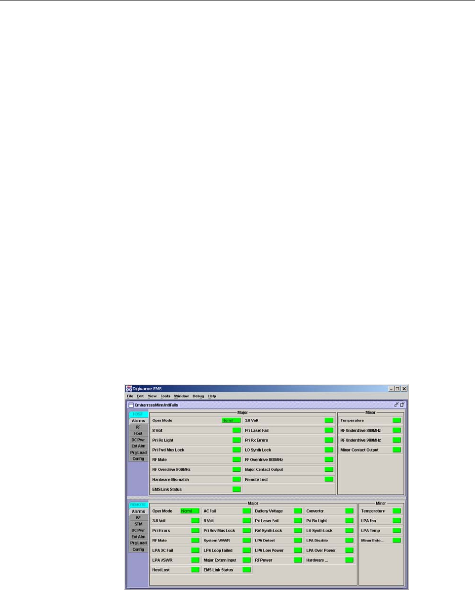
ADCP-75-187 • Issue 3 • September 2006 • Section 2: DESCRIPTION
Page 2-17
© 2006, ADC Telecommunications, Inc.
T1 system, DS0 with RS232 conversion, or other medium. Cables and equipment (not provided)
to support the RS-232 interface connection between the EMS computer and the NOC interface
are required.
The SNMP interface connection between the EMS computer and the SNMP manager requires
that the EMS computer be equipped with an Ethernet port. The link between the EMS computer
and a network SNMP manager would generally be supported by a Local Area Network (LAN).
Cables and equipment (not provided) to support the connection between the EMS computer and
the LAN are required.
5.5 Digivance Software User Interfaces
The Digivance EMS provides three software user interfaces: the EMS Graphical User Interface
(GUI), the Network Operation Center–Network Element Manager (NOC/NEM) interface, and
the SNMP interface. The EMS GUI, the NOC interface, and the SNMP interface provide the
same basic functions. However, the NOC interface and the SNMP interface cannot be used to
download new system software to the Digivance system. In addition, the SNMP interface
cannot be used to assign a system site number to a HU/RU pair during installation.
The EMS GUI is used for local control and monitoring operations. The EMS GUI consists of a
series of displays and screens, such as the one shown in Figure 2-8, that provide the user with
alarm and status information and that allow the user to set various operating parameters.
Directives are implemented by pointing and clicking on the desired action and also by entering
text in various dialog boxes. Refer to the Digivance Element Management System User Manual
(see Related Publications section) for additional information.
Figure 2-8. Typical EMS Graphical User Interface – Host/Remote Alarms Display
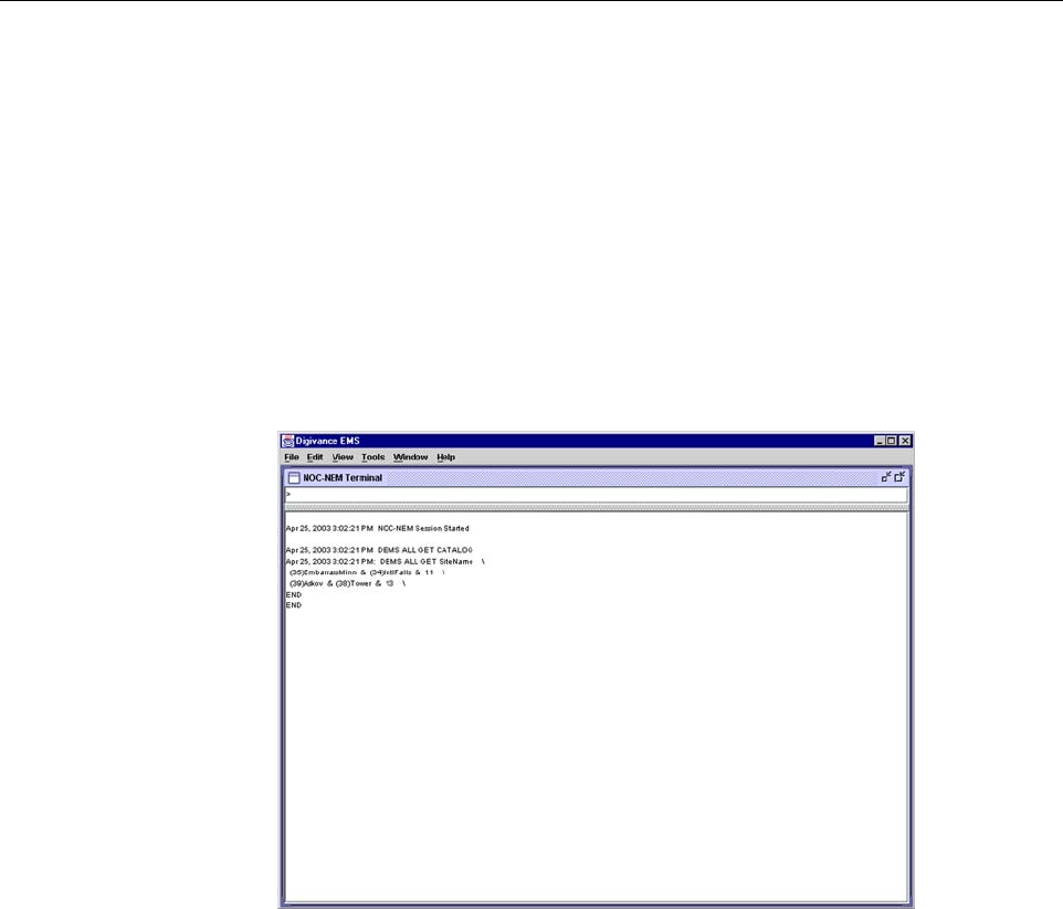
ADCP-75-187 • Issue 3 • September 2006 • Section 2: DESCRIPTION
Page 2-18
© 2006, ADC Telecommunications, Inc.
The NOC/NEM interface is a text-based command line interface that is used for remote control
and monitoring operations (except software download). The NOC/NEM interface consists of
defined ASCII text strings that are input as SET or GET commands followed by the action or
information required. A text string response is received from the specified Digivance system or
systems to confirm the requested action or to report the requested information. Examples of
several typical NOC-NEM interface commands and the responses received are shown in
Figure 2-9. The NOC/NEM interface requires only a VT100 terminal/emulator or a PC-type
computer that is loaded with a communication software such as Procomm Plus. While primarily
intended for use at the NOC, the NOC/NEM interface commands may also be input locally
from the EMS computer. Refer to the Digivance Element Management System User Manual
(see Related Publications section) for additional information.
Figure 2-9. NOC/NEM Interface Typical Commands
The SNMP interface is used for remote control and monitoring operations (except software
download and site number assignment). The SNMP interface uses a Management
Information Base (MIB) to define a list of identifiers that are supported by the SNMP agent.
The SNMP manager communicates with the SNMP agent over a LAN. Directives, based on the
MIB identifier, are issued by the SNMP manager to the SNMP agent along with instructions to
either get the specified identifier or set the specified identifier. The directive is then executed on
the Digivance system by the SNMP agent. The SNMP agent also has the ability to send
autonomous messages (called traps) to the SNMP manager to report changes in the status of the
managed system. The SNMP manager Stargazer Version 8.0 is available from ADC for use with
the SNMP agent. Other SNMP managers are available from various network management
software venders. Refer to the SNMP Agent Software User Manual (see Related Publications
section) for additional information.

ADCP-75-187 • Issue 3 • September 2006 • Section 2: DESCRIPTION
Page 2-19
© 2006, ADC Telecommunications, Inc.
6 SPECIFICATIONS
Refer to the following tables for the system, host unit, and remote unit specifications. All
specifications apply after a five minute warm-up period.
Table 2-5 – SCS 800/900 MHz SMR system nominal specifications
Table 2-6 – SCS 800 MHz system nominal specifications
Table 2-7 – SCS 1900 MHz system nominal specifications
Table 2-8 – Host Unit nominal specifications
Table 2-9 – WDM nominal specifications
Table 2-10 – Remote Unit nominal specifications

ADCP-75-187 • Issue 3 • September 2006 • Section 2: DESCRIPTION
Page 2-20
© 2006, ADC Telecommunications, Inc.
Table 2-5. SCS 800/900 MHz SMR System Nominal Specifications
PARAMETER SPECIFICATION REMARKS
Optical - Host and Remote Unit
Fiber type 9/125, single-mode
Number of fibers required 1 for single-band remote unit
2 for dual-band RU
All SCS remote units include a
WDM.
Forward path wavelength 1550 nm
Reverse path wavelength 1310 nm
Optical transmit power output
Host Unit
Remote Unit
0 dBm
+1.3 dBm (includes WDM inser-
tion loss)
Optical budget 25 dB For optical BER of 10–6
Optical Receiver Input Maximum –15 dBm
Optical connectors UPC/SC Host unit
OptiTap APC/SC Remote unit
RF Forward Path - 800/900 MHz
System bandwidth 18 MHz
5 MHz
800 MHz transmit
900 MHz transmit
Frequency range 851–869 MHz
935–940 MHz
Gain of forward path
(Host input to Remote primary
antenna port)
78.1 dB (typical) At band center, room tempera-
ture, and 0 dB attenuation set-
ting. Includes power amplifier.
Gain flatness
Band flatness
Channel flatness
± 2.0 dB across freq. range
± 1.5 dB variation across any
1.25 MHz channel
Gain variation ± 3 dB over temp and unit-to-
unit
Propagation delay < 6 μs (typical) Excludes fiber delay
Configurable propagation delay
Range
Step size
0 to 63 μs
0.1μs ± 100 ns
Plus standard propagation delay
Spurious
In-band self generated
Dynamic range (noise floor)
<–13 dBm at remote output
<–60 dBc at 30 KHz bandwidth
Transmit peak-to-average >10 dB
Two-tone Intermodulation <–52 dBc two tones @ 5 Watts each
Nominal composite RF input
signal level
–40 dBm at 0 dB attenuation
–9 dBm at max. attenuation
–20 dBm is the optimal RF input
signal level.
Configurable input level
Range
Step size
31 dB
1 ± 0.5 dB ±10% of attenuation
monotonic

ADCP-75-187 • Issue 3 • September 2006 • Section 2: DESCRIPTION
Page 2-21
© 2006, ADC Telecommunications, Inc.
Note: Per Industry Canada Section 5.3 - The rated output power of this equipment is for single
carrier operation. For situations where multiple carrier signals are present, the rating would have
to be reduced by 3.5 dB, especially where the output signal is re-radiated and can cause
interference to adjacent band users. This power reduction is to be by means of input power or
gain reduction and not by an attenuator at the output of the device.
Composite RF Output power of both
bands (see Note 1at end of table)
38.1 dBm (6.5 Watts) at remote
antenna port with –40 dBm input
10 Watts at LPA output
Configurable RF Output
Range
Step size
31 dB at remote unit
1 ± 0.5 dB ± 10% of attenuation
monotonic
Transmit path insertion loss 1.9 dB typical
RF Reverse Path - 800/900 MHz
System bandwidth 18 MHz
5 MHz
800 MHz receive
900 MHz receive
Frequency range 806–824 MHz
896–901 MHz
Propagation delay < 8 μs (typical) Excludes fiber delay
Configurable propagation delay
Range
Step size
Up to 63 μs
0.1μs ±1 100 ns
Plus standard propagation delay
Gain of reverse path
Overall gain
Gain variation
30 ± 2 dB at band center at room
temperature
3 dB over temperature
Gain flatness
Band flatness
Channel flatness
± 2.0 dB across frequency range
± 1.5 dB variation across any
1.25 MHz channel
Out-of-band rejection –40 dB at > 12.5 MHz from cen-
ter of subband
Spurious (in-band self gener-
ated)
–110 dBm referred to input
Intermodulation –62 dBc two tones @ –50 dBm
System noise figure 9 dB at mid-band
Configurable RF output
Range
Step size
31 dB
1 ± 0.5 dB ± 10% of attenuation
monotonic
Blocking dynamic range 70 dB
Level limiting ALC threshold –40 dBm ± 3 dB instantaneous
Level limiting ALC range 27 dB
Table 2-5. SCS 800/900 MHz SMR System Nominal Specifications, continued
PARAMETER SPECIFICATION REMARKS

ADCP-75-187 • Issue 3 • September 2006 • Section 2: DESCRIPTION
Page 2-22
© 2006, ADC Telecommunications, Inc.
Table 2-6. SCS 800 MHz System Nominal Specifications
PARAMETER SPECIFICATION REMARKS
Optical - Host and Remote Unit
Fiber type 9/125, single-mode
Number of fibers required 1 for single-band remote unit
2 for dual-band RU
All SCS remote units include a
WDM.
Forward path wavelength 1550 nm
Reverse path wavelength 1310 nm
Optical transmit power output
Host Unit
Remote Unit
0 dBm
+1.3 dBm (includes WDM inser-
tion loss)
Optical budget 25 dB For optical BER of 10–6
Optical Receive Input Maximum –15 dBm
Optical connectors UPC/SC Host unit
OptiTap APC/SC Remote unit
RF Forward Path - 800 MHz
System bandwidth
A band
B band
11 and 1.5 MHz
10 and 2.5 MHz
Frequency range
A band
B band
869–880 and 890–891.5 MHz
880–890 and 891.5–894 MHz
Out-of-band emissions
Primary –13 dBm per 1 MHz bandwidth
from 10 kHz to 20 GHz
Gain of forward path
(Host input to Remote primary
antenna port)
78.5 dB (typical) At band center, room tempera-
ture, and 0 dB attenuation set-
ting. Includes power amplifier.
Gain flatness
Band flatness
Channel flatness
± 2.0 dB across freq. range
± 1 dB variation across any 1.25
MHz channel
Gain variation ± 3 dB over temp and unit-to-
unit
Out-of-band rejection –40 dB at > ±17.5 MHz from
center of subband
Propagation delay < 6 μs (typical) Excludes fiber delay
Configurable propagation delay
Range
Step size
Up to 63 μs
0.1μs ± 100 ns
Plus standard propagation delay
Spurious
In-band self generated
Free dynamic range
<–13 dBm at remote output
<–60 dBc at 30 kHz bandwidth
Transmit peak-to-average >10 dB

ADCP-75-187 • Issue 3 • September 2006 • Section 2: DESCRIPTION
Page 2-23
© 2006, ADC Telecommunications, Inc.
Two-tone Intermodulation <–55 dBc at remote output Two tones @ 5 Watts each
CDMA Intermodulation
885 kHz to 1.25 MHz
1.25 to 1.98 MHz
1.98 to 2.25 MHz
–45 dBc per 30 kHz
–8 dBm per 30 kHz
–55 dBc per 30 kHz
Absolute level
Nominal composite RF input
signal level
–40 dBm at 0 dB attenuation
–9 dBm at max. attenuation
An input signal level of –40 dBm
provides maximum output power
Configurable input level
Range
Step size
31 dB
1 ± 0.5 dB ±10% of attenuation
monotonic
Composite RF Output power
(see Note 1at end of table)
38.5 dBm (7.0 Watts) at remote
antenna port with –40 dBm input
10 Watts at LPA output
Configurable RF Output
Range
Step size
31 dB at remote unit
1 ±0.5 dB ±10% of attenuation
monotonic
Transmit path insertion loss 2.5 dB maximum
RF Reverse Path - 800 MHz
System bandwidth
A band
B band
11 and 1.5 MHz
10 and 2.5 MHz
Frequency range
A band
B band
824–835 and 845–846.5 MHz
835–845 and 846.5–849 MHz
Propagation delay 6 μs Excludes fiber delay
Configurable propagation delay
Range
Step size
Up to 63 μs
0.1μs ±1 100 ns
Plus standard propagation delay
Gain flatness
Band flatness
Channel flatness
1.5 dB across frequency range
±1 dB variation across any 1.25
MHz channel
Gain of reverse path
Overall gain
Gain variation
30 ± 2 dB at band center at room
temperature
3 dB over temperature
ALC not invoked
ALC not invoked
Out-of-band rejection –40 dB at > ±17.5 MHz from
center of subband
ALC not invoked
Spurious (in-band self gener-
ated)
–110 dBm referred to input ALC not invoked
Intermodulation –62 dBc two tones at –50 dBm
System noise figure 8 dB at mid-band ALC not invoked
Table 2-6. SCS 800 MHz System Nominal Specifications, continued
PARAMETER SPECIFICATION REMARKS

ADCP-75-187 • Issue 3 • September 2006 • Section 2: DESCRIPTION
Page 2-24
© 2006, ADC Telecommunications, Inc.
Note: Per Industry Canada Section 5.3 - The rated output power of this equipment is for single
carrier operation. For situations where multiple carrier signals are present, the rating would have
to be reduced by 3.5 dB, especially where the output signal is re-radiated and can cause
interference to adjacent band users. This power reduction is to be by means of input power or
gain reduction and not by an attenuator at the output of the device.
Configurable RF output
Range
Step size
31 dB
1 ± 0.5 dB ± 10% of attenuation
monotonic
Blocking dynamic range 70 dB
Level limiting ALC threshold –40 dBm ± 3 dB instantaneous
Level limiting ALC range 30 dB
RF Forward and Reverse Path
Modulation Accuracy
Service/Mod Type/Parameter
TDMA/n/4-DQSK/rms EVM
GSM/GMSK/rms phase error
EDGE/8PSK/rms EVM
EIA-97D/CDMA/rho factor
7%
4º
7%
.97%
Table 2-6. SCS 800 MHz System Nominal Specifications, continued
PARAMETER SPECIFICATION REMARKS

ADCP-75-187 • Issue 3 • September 2006 • Section 2: DESCRIPTION
Page 2-25
© 2006, ADC Telecommunications, Inc.
Table 2-7. SCS 1900 MHz System Nominal Specifications
PARAMETER SPECIFICATION REMARKS
Optical - Host and Remote Unit
Fiber type 9/125, single-mode
Number of fibers required 1 for single-band remote unit
2 for dual-band RU
All SCS remote units include a
WDM.
Forward path wavelength 1550 nm
Reverse path wavelength 1310 nm
Optical transmit power output
Host Unit
Remote Unit
0 dBm
+1.3 dBm (includes WDM inser-
tion loss)
Optical budget 25 dB For optical BER of 10–6
Optical Receive Input –15 dBm
Optical connectors
Host Unit
Remote Unit
UPC/SC Host unit
OptiTap APC/SC Remote unit
RF Forward Path - 1900 MHz
System Bandwidth 20 MHz AD band, 25 MHz
DBE, BEF, and EFC bands.
Frequency range
AD
DBE
BEF
EFC
1930 to 1950 MHz
1945 to 1970 MHz
1950 to 1975 MHz
1965 to 1990 MHz
Out-of-band emissions
(Primary)
–13 dBm per 1 MHz bandwidth
from 10 kHz to 20 GHz
Gain of forward path
(Host input to Remote primary
antenna port)
77.7 dB (typical) At band center, room tempera-
ture, and 0 dB attenuation set-
ting. Includes power amplifier.
Gain flatness
Band flatness
Channel flatness
± 1.5 dB across freq. range
± 1 dB variation across any 1.25
MHz channel
Gain variation ± 3 dB over temp and unit-to-
unit
Out-of-band rejection –40 dB at > ±17.5 MHz from
center of subband
Propagation delay < 2.5 μs Excludes fiber delay
Configurable propagation delay
Range
Step size
Up to 63 μs
0.1μs ± 100 ns
Plus standard propagation delay

ADCP-75-187 • Issue 3 • September 2006 • Section 2: DESCRIPTION
Page 2-26
© 2006, ADC Telecommunications, Inc.
Spurious
In-band self generated
Free dynamic range
–13 dBm at remote output
60 dB at 30 kHz bandwidth
Transmit peak-to-average 10 dB
Two-tone Intermodulation –55 dBc at remote output two tones at 5 Watts each
CDMA Intermodulation
885 kHz to 1.25 MHz
1.25 to 1.98 MHz
1.98 to 2.25 MHz
–45 dBc per 30 kHz
–8 dBm per 30 kHz
–55 dBc per 30 kHz
Absolute level
Nominal composite RF input
signal level
–40 dBm at 0 dB attenuation
–9 dBm at max. attenuation
An input signal level of –40 dBm
provides maximum output power
Configurable input level
Range
Step size
31 dB
1 ± 0.5 dB ±10% of attenuation
monotonic
Composite RF Output power
(see Note 1 at end of table)
37.7 dBm (5.9 Watts) at remote
antenna port with –40 dBm input
Configurable RF Output
Range
Step size
31 dB at remote unit
1 ±0.5 dB ±10% of attenuation
monotonic
Transmit path insertion loss 2.4 dB maximum
RF Reverse Path - 1900 MHz
System Bandwidth 20 MHz AD band, 25 MHz
DBE, BEF, and EFC bands.
Frequency range
AD
DBE
BEF
EFC
1850 to 1870 MHz
1865 to 1890 MHz
1870 to 1895 MHz
1885 to 1910 MHz
Propagation delay 2.5 μs Maximum Excludes fiber delay
Configurable propagation delay
Range
Step size
0 to 63 μs
0.1μs ±1 100 ns
Plus standard propagation delay
Gain flatness
Band flatness
Channel flatness
1.5 dB across frequency range
±1 dB variation across any 1.25
MHz channel
Gain of reverse path
Overall gain
Gain variation
30 ± 2 dB at band center at room
temperature
3 dB over temperature
ALC not invoked
ALC not invoked
Out-of-band rejection –40 dB at > ±17.5 MHz from
center of subband
ALC not invoked
Table 2-7. SCS 1900 MHz System Nominal Specifications, continued
PARAMETER SPECIFICATION REMARKS

ADCP-75-187 • Issue 3 • September 2006 • Section 2: DESCRIPTION
Page 2-27
© 2006, ADC Telecommunications, Inc.
Note: Per Industry Canada Section 5.3 - The rated output power of this equipment is for single
carrier operation. For situations where multiple carrier signals are present, the rating would have
to be reduced by 3.5 dB, especially where the output signal is re-radiated and can cause
interference to adjacent band users. This power reduction is to be by means of input power or
gain reduction and not by an attenuator at the output of the device.
Spurious (in-band self gener-
ated)
–110 dBm referred to input ALC not invoked
Intermodulation –62 dBc two tones at –50 dBm
System noise figure 8 dB at mid-band ALC not invoked
Configurable RF output
Range
Step size
31 dB
1 ± 0.5 dB ± 10% of attenuation
monotonic
Blocking dynamic range 70 dB
Level limiting ALC threshold –40 dBm ± 3 dB instantaneous
Level limiting ALC range 30 dB
RF Forward and Reverse Path
Modulation Accuracy
Service–Mod Type–Parameter
TDMA–π/4-DQSK–rms EVM
GSM–GMSK–rms phase error
EDGE–8PSK–rms EVM
EIA-97D–CDMA–rho factor
7%
4º
7%
0.97%
Table 2-7. SCS 1900 MHz System Nominal Specifications, continued
PARAMETER SPECIFICATION REMARKS

ADCP-75-187 • Issue 3 • September 2006 • Section 2: DESCRIPTION
Page 2-28
© 2006, ADC Telecommunications, Inc.
Table 2-8. Host Unit Nominal Specifications
PARAMETER SPECIFICATION REMARKS
Physical/Environmental/
Electrical - Host Unit
Dimensions (H×W×D)
Rear Access
Front Access
3.5 × 17.1 × 12.2 inches
(88 × 433 × 311 mm)
3.5 × 17.2 × 15.3 inches
(88 × 437 × 389 mm)
Dimension for width does not
include the mounting brackets
which can be installed for either
19- or 23-inch racks.
Mounting 19- or 23-inch rack EIA or WECO
Weight 18 lbs. (8.2 kg)
Weather resistance Indoor installation only
Operating temperature 0º to 50º C (32º to 122º F)
Storage temperature –40º to 70º C (–40º to 158ºF)
Humidity 10% to 90% No condensation
Optical ports UPC/SC
External alarm connector Screw-type terminals NO and NC relay contacts
DC power connector Screw-type terminal strip
RF coaxial cable connectors 50 ohm N-type (female) 50 ohms input/output impedance
Service connector DB-9 (female) RS-232 DTE interface
Auxiliary connector DB-9 (female) Not used with SCS systems
CAN connectors RJ-45 jack
Voltage input Nominal ± 24 or ± 48 VDC ± 21 to ± 60 VDC
Power consumption 55 watts
Current rating 1 Amp at –48 VDC
Reliability at 25ºC MTBF 80,000 hours Excluding fans
Table 2-9. Host Unit and Remote Unit WDM Nominal Specifications
PARAMETER SPECIFICATION REMARKS
Optical - WDM
Passband 1310 nm ± 20 nm
1550 nm ± 20 nm
Forward path insertion loss
Host WDM
Remote WDM
0.7 dB
0.3 dB
Does not include connector loss
Reverse path insertion loss
Host WDM
Remote WDM
0.3 dB
0.7 dB
Does not include connector loss
Isolation > 30 dB minimum
Return loss (Reflectance) < –50 dB All input ports

ADCP-75-187 • Issue 3 • September 2006 • Section 2: DESCRIPTION
Page 2-29
© 2006, ADC Telecommunications, Inc.
Note: The SCS remote unit has been tested to assure it meets the dust and water resistance
requirements of IP67 as specified by IEC Publication 60529. These tests were conducted using
closure caps attached to the remote unit cable ports. To assure the dust and water resistance level
is maintained, it is the responsibility of the user to select AC power, antenna, and fiber optic
cable assemblies that have a dust and water resistance level of IP67 or higher. If user is uncertain
of cable manufacturers that meet this requirement, please contact ADC Technical Assistance.
Table 2-10. Remote Unit Nominal Specifications
PARAMETER SPECIFICATION REMARKS
Physical/Environmental/
Electrical - Remote Unit
Dimensions (L×W×D)
Single-Band
Dual-Band and Interim Single
Band
29.4 × 9.7 × 5.7 inches
(747 × 246 × 145 mm)
37.3 × 10.2 × 7.5 inches
(947 × 259 × 191 mm)
Mounting Pole, wall, or strand mounted Requires accessory kit for strand
mounting
Weight
Single-Band
Dual-Band and Interim Single
Band
51.2 lbs. (23.2 kg)
90.5 lbs. (41.0 kg)
Without solar shields installed
Weather resistance (see Note) NEMA-6, IEC IP67 Indoor or outdoor installation
Lightning protection 20 kA IEC 1000-4-5 8/20 µs
waveform
Provided by external lightning
protector (accessory)
Operating temperature –30º to 50º C (–22º to 122º F)
Storage temperature –40º to 70º C (–40º to 158ºF)
Humidity 10% to 90% No condensation
AC power connector Mini 3-pin 3-wire power cable included
Antenna connector(s) 50 ohm N-type (female) 50 ohms input/output impedance
Optical port(s) APC/SC hardened adapter
Voltage input 90 to 265 VAC, 47 to 63 Hz
60 to 89 VAC, 47 to 63 Hz
Standard
Option
Power consumption
Single-Band (all types)
Dual-Band
300 VA at 120 VAC
600 VA at 120 VAC
Current rating
Single-Band (all types)
Dual-Band
2.5 Amps at 120 VAC
5.0 Amps at 120 VAC
Requires 15 Amp circuit
Reliability at 25ºC MTBF - 50,000 hours

ADCP-75-187 • Issue 3 • September 2006 • Section 2: DESCRIPTION
Page 2-30
© 2006, ADC Telecommunications, Inc.
Blank

ADCP-75-187 • Issue 3 • September 2006 • Section 3: OPERATION
Page 3-1
© 2006, ADC Telecommunications, Inc.
SECTION 3: OPERATION
1 BEFORE STARTING OPERATION. . . . . . . . . . . . . . . . . . . . . . . . . . . . . . . . . . . . . . . . . . . . . . . . . . . . . . . . . . . . .3-1
1.1 Tools and Materials . . . . . . . . . . . . . . . . . . . . . . . . . . . . . . . . . . . . . . . . . . . . . . . . . . . . . . . . . . . . . . .3-1
1.2 Readiness Check . . . . . . . . . . . . . . . . . . . . . . . . . . . . . . . . . . . . . . . . . . . . . . . . . . . . . . . . . . . . . . . . .3-2
2 TURN-UP SYSTEM AND VERIFY OPERATION . . . . . . . . . . . . . . . . . . . . . . . . . . . . . . . . . . . . . . . . . . . . . . . . . . . .3-2
2.1 Reference Procedure: Determine Forward Path Input Signal Level . . . . . . . . . . . . . . . . . . . . . . . . . . . . . . .3-6
2.2 Reference Procedure: Enter Site Name and Site Number. . . . . . . . . . . . . . . . . . . . . . . . . . . . . . . . . . . . . .3-9
2.3 Reference Procedure: Enter Host Forward Attenuation . . . . . . . . . . . . . . . . . . . . . . . . . . . . . . . . . . . . . . 3-11
2.4 Reference Procedure: Determine Output Signal Level at RU Antenna Port . . . . . . . . . . . . . . . . . . . . . . . . . 3-12
2.5 Reference Procedure: Enter Remote Forward Attenuation . . . . . . . . . . . . . . . . . . . . . . . . . . . . . . . . . . . .3-13
2.6 Reference Procedure: Enter Host Reverse Attenuation . . . . . . . . . . . . . . . . . . . . . . . . . . . . . . . . . . . . . . 3-15
2.7 Reference Procedure: Enter Host Forward and Reverse Delay . . . . . . . . . . . . . . . . . . . . . . . . . . . . . . . . . 3-16
_________________________________________________________________________________________________________
1 BEFORE STARTING OPERATION
This section provides guidelines for turning-up the Digivance system, verifying that all units are
operating properly, testing to ensure that all performance requirements are satisfied, and
correcting any installation problems. This process assumes that the various units have been
installed in accordance with the system design plan.
1.1 Tools and Materials
The following tools and materials are required in order to complete the procedures in this
section:
• Portable spectrum analyzer or RF power meter
• DC voltmeter
• External RF and optical attenuators (if specified in system design plan)
• PC-type computer with Digivance Element Management System (EMS) Version 3.01
software installed
• Straight-through RS-232 DB-9 interface cable (accessory)
•Handset
•Pencil or pen
• Writing pad
Content Page

ADCP-75-187 • Issue 3 • September 2006 • Section 3: OPERATION
Page 3-2
© 2006, ADC Telecommunications, Inc.
1.2 Readiness Check
Before starting the turn-up process, inspect the complete Digivance system to verify that all
components of the system are ready to be powered-up. This will ensure that no units of the
system will be damaged during turn-up and that all existing systems will continue to function
properly.
1.2.1 Host Unit Installation Checks
Complete the following checks at the HU prior to starting the turn-up process:
1. Verify that the ON/OFF switch on the HU is in the OFF position (press O).
2. At the fuse panel, install a 3 Amp GMT fuse in the circuit that supplies DC power to the HU.
3. Using a DC voltmeter, verify that the DC voltage level at the HU power terminals is
between ± 21 to ± 60 VDC (nominal ± 24 or ± 48 VDC). The DC power provided to the
HU can be either polarity.
4. Verify that all electrical and optical connections have been completed and that all optical
fibers, coaxial cables, and wires are properly routed and secured.
1.2.2 Remote Unit Installation Checks
Complete the following checks at the RU prior to starting the turn-up process:
1. Verify that all electrical and optical connections have been completed and that all optical
fibers, coaxial cables, and wires are properly routed and secured.
2. At the AC breaker box, make sure the circuit breaker for the circuit that supplies AC power
to the RU is in the open (off) position.
2 TURN-UP SYSTEM AND VERIFY OPERATION
The process of turning-up the system and verifying operation involves powering up the various
system components, verifying that the LED indicators show normal operation, setting the site
number and name, adjusting the RF signal levels, and adjusting the path delay.
Note: When connecting the equipment to the supply circuit, be sure to check equipment
nameplate ratings to avoid overloading circuits which may cause damage to over-current
protection devices and supply wiring.
Note: SCS systems that include a dual-band RU are comprised of two systems that operate
and function independently of each other. Each system can be independently turned-up,
tested, and placed into service. The EMS will recognize each system regardless of the
frequency/band and will display the appropriate screens. The frequency/band can be
verified by clicking on the HOST Host tab and on the REMOTE STM tab. The frequency/
band for the selected system will be displayed on the right side of the screen.

ADCP-75-187 • Issue 3 • September 2006 • Section 3: OPERATION
Page 3-3
© 2006, ADC Telecommunications, Inc.
Each Digivance system must be turned-up separately before being networked together with
multiple systems through the CAN interface. Use the following procedure to turn-up each
Digivance system:
1. Temporarily disconnect the external alarm system or notify the alarm system provider that
testing is in progress.
2. If the HU is networked together with multiple HU’s, temporarily disconnect the CAN cables
from the NET IN and NET OUT ports of the HU.
3. Determine if the forward path composite input signal level at the host unit RF IN port(s) is
appropriate to produce the required RF output signal level. Note that 800/900 MHz SMR
host units have two forward path RF ports. Adjust by installing an external attenuator if
necessary. For 800/900 MHz SMR systems., the optimum input signal level is –20 dBm
Refer to Section 2.1 for the calculation and adjustment procedure.
4. At the HU: Place the ON/OFF switch on the HU in the ON position (press I).
5. At the RU: Place the AC circuit breaker switch in the closed (ON) position.
6. Wait 6 to 10 seconds for the HU and the RU to initialize and then observe the LED
indicators on the HU and RU. Refer to Section 4: Maintenance for the troubleshooting
procedures if the indicators do not respond as specified in Table 3-1.
Table 3-1. LED Indicator Operation at Initial Turn-Up
7. Measure the input optical power level at the HU and RU and verify that the optical power
level received at the HU and RU is within –15 to –25 dBm. Refer to Section 4:
Maintenance for the optical power test procedure.
8. Connect the EMS computer (if not already connected) to the SERVICE connector on the
HU front panel. If necessary, a separate laptop computer loaded with the EMS software
can be temporarily connected and used to initially configure the system.
Note: By default, all HU’s and RU’s are programmed with the same site number and
name. This can cause problems for the EMS if multiple HU’s with the same site number
and site name are networked together through the CAN interface. It is therefore necessary
to temporarily disconnect the CAN interface cables from the HU when it is being
configured for operation until a unique site number and name can be assigned.
REAR ACCESS HOST UNIT FRONT ACCESS HOST UNIT REMOTE UNIT
POWER – Green POWER – Green STATUS – Off
Note: This LED
will turn red for
6 to 10 seconds
while the RU
initializes and
then turn off.
STANDBY – Off STANDBY – Off
HOST UNIT – Green HOST UNIT – Green
REMOTE UNIT – Green REMOTE UNIT – Green
DRIVE 851–869 – Green, Yellow, or Red
DRIVE 935–940 – Green, Yellow, or Red
DRIVE – Green, Yellow, or Red
FWD/REV (PORT 1/PORT 2) – Green FWD/REV (PORT 1/PORT 2) – Green
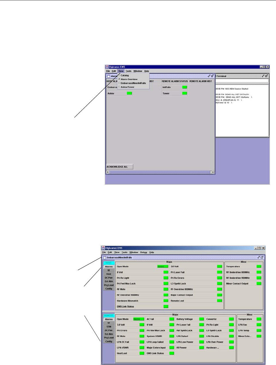
ADCP-75-187 • Issue 3 • September 2006 • Section 3: OPERATION
Page 3-4
© 2006, ADC Telecommunications, Inc.
9. Start up the EMS software program. The EMS main window will open as shown in
Figure 3-1. The EMS software should be installed on a PC-type computer and the PC’s
COMM port should be configured to interface with the HU. For information about
installing the EMS software and configuring the PC’s COMM port, refer to the Digivance
Element Management System User Manual (see Related Publications section).
Figure 3-1. Digivance Element Management System Main Window
10. Open the View drop down menu and connect to the Host and Remote pair by selecting the
“NotNamed/NotNamed” Host/Remote pair. The HOST Alarms display and the REMOTE
Alarms display will open within the main window as shown in Figure 3-2.
Figure 3-2. Typical Host and Remote Alarms Display
Click to view drop
down menu
Clicking on the tabs in
this list will open the cor-
responding display.
Host/Remote pair
site name

ADCP-75-187 • Issue 3 • September 2006 • Section 3: OPERATION
Page 3-5
© 2006, ADC Telecommunications, Inc.
11. New Control program software and FPGA program software will be provided separately
on a “as needed” basis. If new Control and FPGA software is not provided with the
system, proceed to step 12. If a Control and FPGA software upgrade is required, contact
the ADC Technical Assistance Center (see Section 5) for help with the download
procedure.
12. Click on the HOST Config tab and on the REMOTE Config tab (see Figure 3-2). The
HOST Config display and the REMOTE Config display will open within the main window.
13. Enter the Site Name and Site Number for both the HOST and the REMOTE unit. Refer to
Section 2.2 for details.
14. If the Digivance system will be networked together with other Digivance systems,
reconnect the CAN cables to the HU’s NET IN and NET OUT ports.
15. Verify that no Major or Minor alarms are being reported in either the HOST or REMOTE
Alarm displays (except as indicated in the note below) and that all alarm fields are green.
16. Click on the HOST RF tab (see Figure 3-2). The HOST RF display will open within the
main window.
17. Enter the Host Fwd Att (Forward Attenuation) value. This sets the forward input RF
signal level at the HU. Refer to Section 2.3 for details. By default, this value is set to 31
dB. If the DRIVE LED on the HU front panel was red, it should turn green when this step
is completed. Note that 800/900 MHz SMR HU’s have two DRIVE LED’s.
18. Determine if the RF output power at the RU ANTENNA is at the correct level up to a
composite maximum of +38.1 dBm (6.5 Watts) for 800/900 MHz SMR systems,
+38.5 dBm (7.0 Watts) for 800 MHz systems, and +37.7 dBm (5.9 Watts) for 1900 MHz
systems. Refer to Section 2.4 for details.
19. Click on the REMOTE RF tab (see Figure 3-2). The REMOTE RF display will open
within the main window.
20. Enter the Remote Fwd Att value. This adjusts the RF output signal level at the HU
ANTENNA port. By default this value is set to 31 dB. Refer to Section 2.5 for details.
21. Click on the HOST RF tab (see Figure 3-2). The HOST RF display will open within the
main window.
22. Enter the Host Rev Att (Reverse Attenuation) values. This sets the reverse output RF
signal levels at the host unit RF OUT port(s). By default each value is set to 31 dB. Refer
to Section 2.6 for details. Note that 800/900 MHz SMR host units have two REVERSE RF
OUT ports.
23. If a delay adjustment is required, enter the Host Fwd Delay and Host Rev Delay values.
By default, the delay values are set to 0. Refer to Section 2.7 for details.
Note: The Site Name and Site Number must be unique for each Digivance system.
Note: The Host RF Underdrive may indicate a minor alarm until the Host Fwd Att and
Remote Fwd Att values are set.

ADCP-75-187 • Issue 3 • September 2006 • Section 3: OPERATION
Page 3-6
© 2006, ADC Telecommunications, Inc.
24. If a separate laptop computer loaded with the EMS software was used to initially
configure the system, disconnect the laptop computer from the SERVICE connector.
25. Reconnect the external alarm system or notify the alarm system provider that the turn-up
process has been completed.
2.1 Reference Procedure: Determine Forward Path Input Signal Level
The level of the composite RF input signals received at the host unit FORWARD RF IN port(s)
will vary depending on the EBTS, the cable loss, the number of channels present, and the
required forward path composite power. If maximum composite RF output is required at the
RU, the level of the composite RF input signal received at the HU must fall within a range of –9
to –40 dBm. If the signal level is not within this range, it must be adjusted using an external
attenuator. Note that the 800/900 MHz SMR host unit has two FORWARD RF IN ports. Use the
851–869 FORWARD RF IN port to complete this procedure. Then repeat this procedure for the
935–940 FORWARD RF IN port.
If using the Conditioning Panel or Duplexing Panel, refer to the user manual shipped with the
panel (ADCP-75-147) for the procedures for measuring and adjusting the RF input signal level
at the HU. If connecting a single HU to a single EBTS, use the following procedure to measure
and adjust the input RF signal level at the HU:
1. Connect a spectrum analyzer or power meter to the forward path output port at the EBTS.
The required signal levels and test points for 800/900 MHz SMR systems are shown in
Figure 3-3. The required signal levels and test points for 800 MHz and 1900 MHz
systems are shown in Figure 3-4. Note that 800/900 MHz SMR Host Units have two
forward path ports.
2. If using a spectrum analyzer, proceed to step 3. If using a power meter, measure the
composite signal power from the EBTS and then proceed to step 5.
3. Measure the RF level of a single carrier, such as the control channel, in dBm. Make sure
the resolution bandwidth of the spectrum analyzer is 30 kHz. Maximum power in any
channel should not exceed 5W (+37 dB).
4. Calculate the total composite signal power from the EBTS using the following formula:
Ptot = Pc + 10Log N where,
Ptot is the total composite power in dBm
Pc is the power per carrier in dBm as measured in step 3, and
N is the total number of channels.
Note: When two or more HU’s are connected together through the CAN interface, only
one EMS computer is required to manage the networked Digivance systems. The EMS
computer may be connected to the SERVICE port on any one of the HUs in the network.
Note: The optimum level for an 800/900 MHz SMR composite input signal is –20 dBm
Note: Check the input rating of the test equipment and the output rating of the EBTS. To
avoid burning out the spectrum analyzer or power meter, it may be necessary to insert a
30 dB 100W (or similar) attenuator between the EBTS and test equipment.
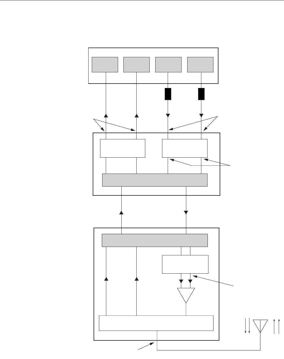
ADCP-75-187 • Issue 3 • September 2006 • Section 3: OPERATION
Page 3-7
© 2006, ADC Telecommunications, Inc.
Figure 3-3. Signal Levels, Test Points, and Adjustments for 800/900 MHz SMR Systems
FORWARD PATH
INPUT SIGNAL LEVEL
AT HOST UNIT
(-20 dBm OPTIMAL
COMPOSITE FOR
FULL POWER)
HOST UNIT
REMOTE UNIT
ENHANCED BASE TRANSCEIVER STATION
20577-A
OPTICAL LINK
ANTENNA
QUADRAPLEXER/FILTER
FORWARD PATH SIGNAL
LEVEL AS SET BY HOST
FORWARD PATH
ATTENUATORS
(ADJUST TO -40 dBm
COMPOSITE
FOR FULL POWER)
REVERSE PATH OUTPUT
SIGNAL LEVEL AS SET BY HOST
REVERSE PATH ATTENUATORS
MAXIMUM OUTPUT SIGNAL
LEVEL AT ANTENNA PORT
(38.1 dBm AT FULL POWER)
FORWARD PATH SIGNAL
LEVEL AS SET BY REMOTE
FORWARD PATH
ATTENUATORS
LPA
EXTERNAL
ATTENUATORS
851-869
TRANS-
MITTER
935-940
TRANS-
MITTER
0 to 31 dB
ATTENUATORS
(HOST FWD ATT)
0 to 31 dB
ATTENUATORS
(HOST REV ATT)
0 to 31 dB
ATTENUATORS
(REMOTE FWD ATT)
RF, OPTICS,
AND CONTROL
RF, OPTICS,
AND CONTROL
896-901
RECEIVER
806-824
RECEIVER
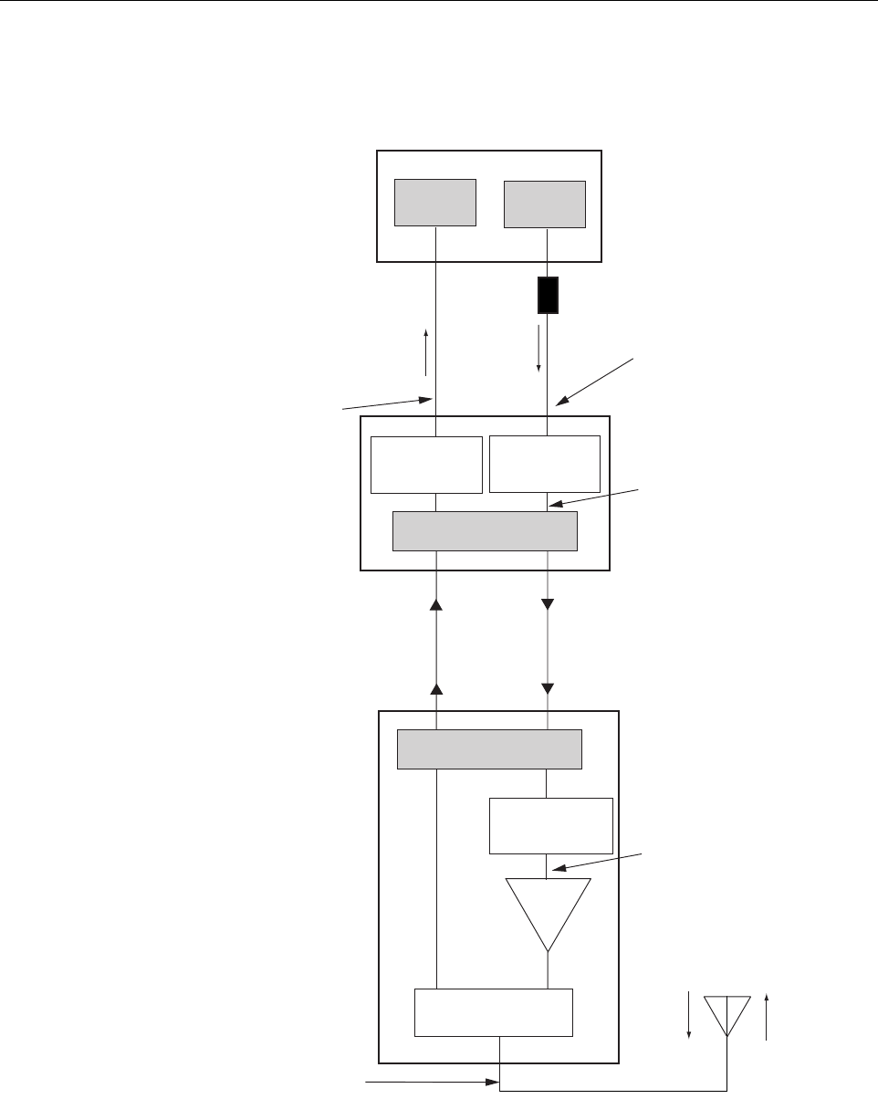
ADCP-75-187 • Issue 3 • September 2006 • Section 3: OPERATION
Page 3-8
© 2006, ADC Telecommunications, Inc.
Figure 3-4. Signal Levels, Test Points, and Adjustments for 800 MHz and 1900 MHz Systems
FORWARD PATH
INPUT SIGNAL LEVEL
AT HOST UNIT
(-20 dBm TYPICAL
COMPOSITE FOR
FULL POWER)
HOST UNIT
PRIMARY
ANTENNA
LPA
REMOTE UNIT
ENHANCED BASE TRANSCEIVER STATION
20653-A
EXTERNAL
ATTENUATOR
TRANS-
MITTER
RECEIVER
0 to 31 dB
ATTENUATOR
(HOST REV ATT)
0 to 31 dB
ATTENUATOR
(HOST FWD ATT)
RF, OPTICS,
AND CONTROL
0 to 31 dB
ATTENUATOR
(REMOTE FWD ATT)
OPTICAL LINK
RF, OPTICS,
AND CONTROL
DUPLEXER
FORWARD PATH SIGNAL
LEVEL AS SET BY HOST
FORWARD PATH ATTENUATOR
(ADJUST TO -40 dBm
COMPOSITE FOR
FULL POWER)
REVERSE PATH OUTPUT
SIGNAL LEVEL AS SET BY HOST
REVERSE PATH ATTENUATOR
MAXIMUM OUTPUT SIGNAL
LEVEL AT ANTENNA PORT
AT FULL POWER
38.5 dB FOR 800 MHZ
37.7 FOR 1900 MHZ
FORWARD PATH SIGNAL
LEVEL AS SET BY REMOTE
FORWARD PATH
ATTENUATOR

ADCP-75-187 • Issue 3 • September 2006 • Section 3: OPERATION
Page 3-9
© 2006, ADC Telecommunications, Inc.
5. Determine the total cable loss that is imposed by the forward path coaxial cable that links
the EBTS to the HU and also any insertion loss imposed by splitters or combiners.
6. Subtract the total cable loss and any insertion losses from the total composite power
calculated in step 4.
7. Subtract –20 (optimum input signal level) from the value determined in step 6. The
difference (which should be positive) equals the value of the external attenuator that is
required to reduce the forward path signal level to the optimum level for input to the HU.
The following formula outlines the required calculations for steps 6 and 7:
Ptot – (Cable and insertion loss) – (–20) = Value of external attenuator required
8. Select an attenuator that is as close to the value calculated in step 7 as possible.
9. Install the external attenuator in the coaxial cable that is connected to the corresponding
FORWARD RF IN port at the HU.
10. If turning up an 800/900 MHz SMR system, repeat steps 1–9 for the 935–940 FORWARD
RF IN port at the HU. Install the external attenuator in the coaxial cable that is connected
to the 935–940 FORWARD RF IN port at the HU.
11. Subtract the value of the external attenuator from the total composite signal power (Ptot)
and record the result. This value will be required when setting the attenuation of the HU’s
internal forward path attenuators.
2.2 Reference Procedure: Enter Site Name and Site Number
All HU’s and RU’s are programmed with the same site name and site number. It is therefore
necessary to assign a unique site name and site number to the HU and RU before they can be
connected to the same CAN network. Use the following procedure to assign a unique site name
and number to each HU and RU system:
1. Click on the HOST Config tab and on the REMOTE Config tab. The HOST Config
display and the REMOTE Config display will open within the EMS main window as
shown in Figure 3-5.
2. Click on the HOST Site Name Edit button (see Figure 3-5). The Site Name pop-up
screen will open as shown in Figure 3-6. Enter a unique name for the HOST. The name
may be up to 32 characters long and must not contain any spaces. The name may include
numbers, punctuation, and upper or lower case letters and must always begin with a letter.
Click on OK to close the screen and make the changes take effect.
Note: If the input signal level is already –20 dBm, no external attenuator is required.
Caution: The Host Unit can be damaged if it is overdriven by the EBTS. Always install an
external protective attenuator at the Host Unit FWD RF IN port if the forward path composite
input signal level is greater than –9 dBm.
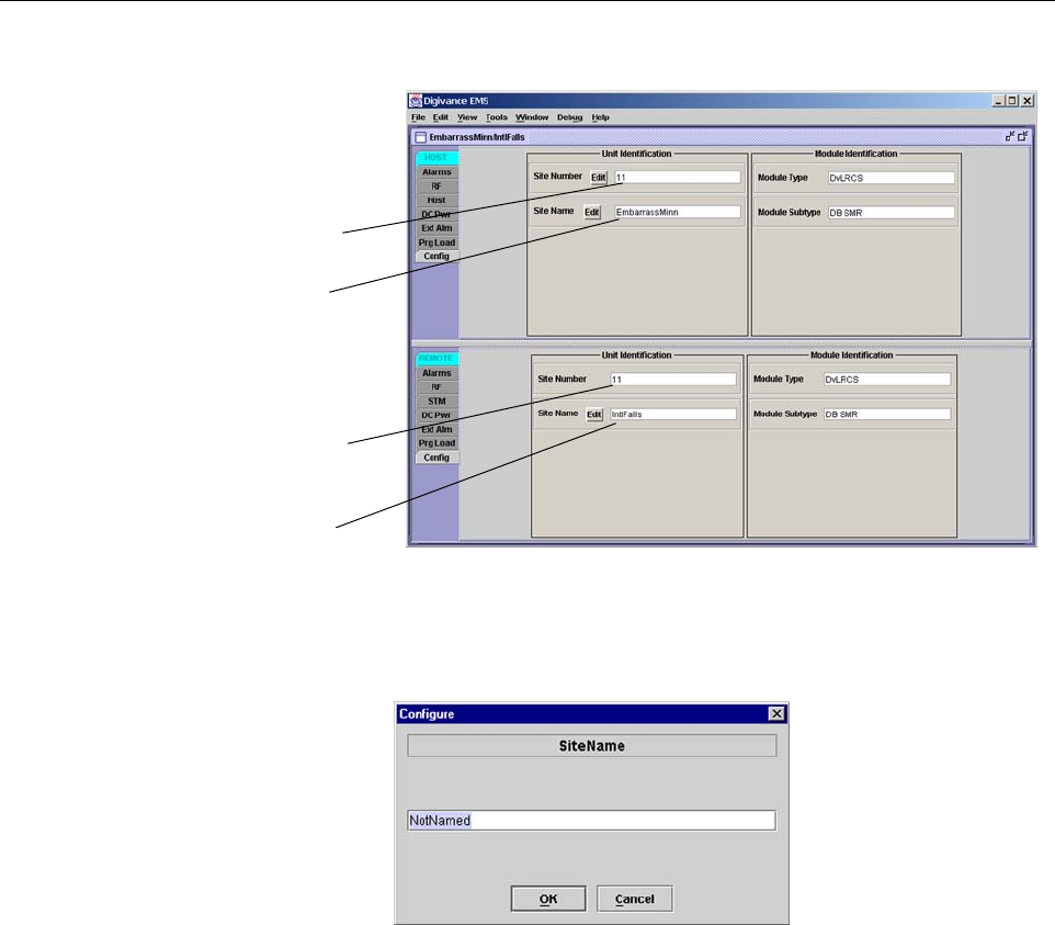
ADCP-75-187 • Issue 3 • September 2006 • Section 3: OPERATION
Page 3-10
© 2006, ADC Telecommunications, Inc.
Figure 3-5. HOST and REMOTE Config Displays
Figure 3-6. HOST Site Name Pop-Up Screen
3. Click on the HOST Site Number Edit button (see Figure 3-5). The Site Number pop-up
screen will open. Enter any number (must be unique) between 1 and 24 and then click on
OK to close the screen and make the changes take effect.
4. Check the REMOTE Site Number field (see Figure 3-5). The REMOTE Site Number
does not have to be entered. When the HOST Site Number is entered, the system will
automatically enter the same number for the REMOTE Site Number.
5. Click on the REMOTE Site Name Edit button (see Figure 3-5). The Site Name pop-up
screen will open. Enter a unique name for the REMOTE. The name may be up to 32
characters long and must not contain any spaces. The name may include numbers,
punctuation, and upper or lower case letters and must always begin with a letter. Click on
OK to close the screen and make the changes take effect.
6. Open the Tools menu at the top of the main window and then select Refresh Catalog to
make the new Host and Remote site names appear in the View menu.
HOST Site Number
HOST Site Name
REMOTE Site Number
(Entered automatically
when the HOST site
number is selected)
REMOTE Site Name
Click on the Edit button
to open pop-up screen
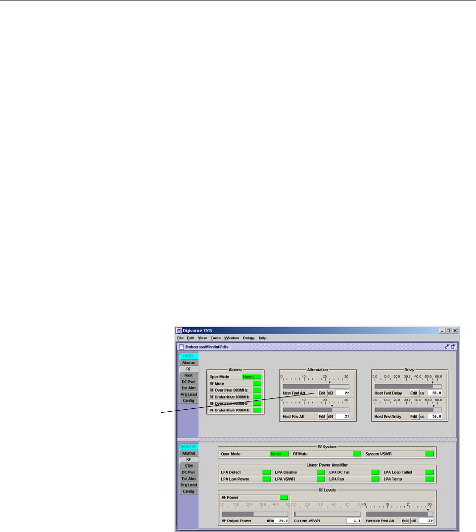
ADCP-75-187 • Issue 3 • September 2006 • Section 3: OPERATION
Page 3-11
© 2006, ADC Telecommunications, Inc.
2.3 Reference Procedure: Enter Host Forward Attenuation
The HU internal forward path attenuator setting determines the maximum composite output
signal level at the RU antenna port. The appropriate attenuation value for any particular system
is based on the number of channels the system is transporting and the signal level of the
composite forward path signals input at the host units RF IN ports. By default, the forward path
attenuator is set to 31 dB.
The maximum output power is 38.1 dBm (6.5 Watts) for 800/900 MHz SMR systems, 38.5 dBm
(7.0 Watts) for 800 MHz systems, and 37.7 dBm (5.9 Watts) for 1900 MHz systems. The total
forward path gain that is provided by the system (with host and remote forward attenuators set to 0
dB) is 78.1 dBm for 800/900 MHz SMR systems, 78.5 dBm for 800 MHz systems, and 77.7 for
1900 MHz systems. For 800/900 MHz SMR systems, this procedure sets the attenuation for both
FORWARD RF IN ports.
Use the following procedure to set the forward path attenuation to provide the maximum
composite output signal level:
1. Click on the HOST RF tab. The HOST RF display will open within the EMS main
window as shown in Figure 3-7.
Figure 3-7. Typical HOST RF Display
2. Click on the Host Fwd Att Edit button (see Figure 3-7). The Host Fwd Att pop-up screen
will open as shown in Figure 3-8.
3. Obtain the value of the total composite input signal level as determined in step 11 of
Section 2.1.
Click on Edit button
to open Host Fwd
Att pop-up screen
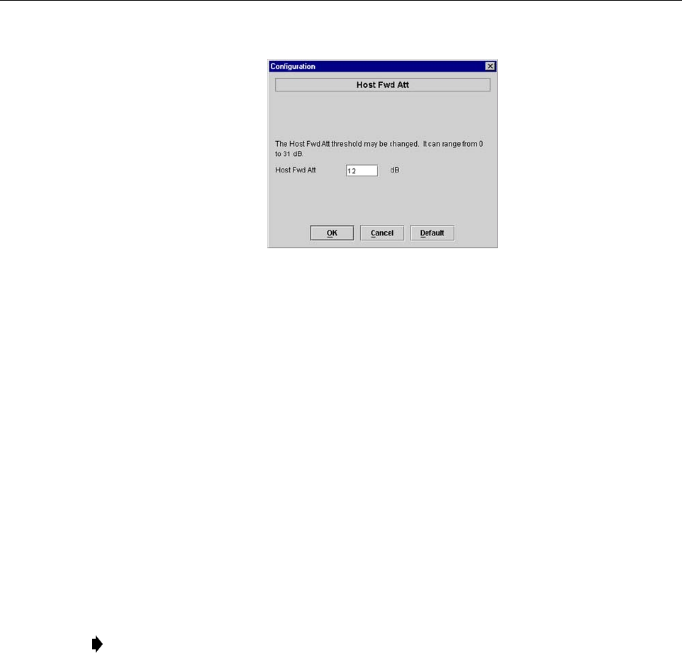
ADCP-75-187 • Issue 3 • September 2006 • Section 3: OPERATION
Page 3-12
© 2006, ADC Telecommunications, Inc.
Figure 3-8. Host Fwd Att Pop-Up Screen
4. Determine the appropriate value to enter for the Host forward path attenuator by
subtracting the required system output level (per system design plan) from the system gain
(78.1 dB for 800/900 MHz SMR, 78.5 for 800 MHz, and 77.7 dB for 1900 MHz) and then
adding the composite input signal level. The result (see sample calculation) is the amount
of attenuation required.
Atten = (System Gain) – (Required System Output Power) + (Composite Input Power)
5. Enter the attenuation value and click OK to close the pop-up screen and to make the
changes take effect.
2.4 Reference Procedure: Determine Output Signal Level at RU Antenna Port
The RF output signal level should be measured at the RU ANTENNA port to verify that the
composite signal level is at the expected level. Use the following procedure to determine the
power level:
1. Place the AC circuit breaker switch (at the RU power panel) in the open (OFF) position.
2. Disconnect the antenna cable from the RU ANTENNA port.
3. Connect a spectrum analyzer or RF power meter to the HU ANTENNA port. (Check the
input rating of the test equipment. Insert a 30 dB 100 W attenuator if necessary.)
4. Place the AC circuit breaker switch (at the RU power panel) in the closed (ON) position.
5. If using a spectrum analyzer, proceed to step 6. If using a power meter, measure the
composite signal power from the RU and then proceed to step 8.
6. Measure the RF level of a single carrier, such as the control channel, in dBm. Make sure
the resolution bandwidth of the spectrum analyzer is 30 kHz.
Note: The RF output signal level measured in this procedure should be approximately
31 dBm less than the output level specified for operation. This is because the factory
default setting for the remote forward attenuator is 31 dB. The final adjustment of the
system RF output signal level will be completed in Section 2.5

ADCP-75-187 • Issue 3 • September 2006 • Section 3: OPERATION
Page 3-13
© 2006, ADC Telecommunications, Inc.
7. Calculate the total composite signal power using the following formula:
Ptot = Pc + 10Log N
Where,
Ptot is the total composite power in dBm
Pc is the power per carrier in dBm as measured in step 6, and
N is the total number of channels.
8. Record the result measured in step 5 or calculated in step 7.
9. Place the AC circuit breaker switch (at the RU power panel) in the open (OFF) position.
10. Disconnect the spectrum analyzer or RF power meter from the HU ANTENNA port.
11. Re-connect the antenna cable to the HU ANTENNA port.
12. Place the AC circuit breaker switch (at the RU power panel) in the closed (ON) position.
2.5 Reference Procedure: Enter Remote Forward Attenuation
The RU internal forward path attenuator setting is used to reduce the power level of the
composite output signals at the RU. The maximum composite output signal level at the RU
antenna port is set using both the HU forward attenuator (see Section 2.3) and the RU forward
attenuator. Component variations may result in the output power at the HU antenna port being
slightly above or below the calculated value. The RU forward attenuator is used in conjunction
with the HU forward attenuator to add or remove attenuation to produce the required output
signal level at the antenna port. The default setting for the RU forward attenuator is 31 dB. Use
the following procedure to change the RU forward attenuation:
1. Click on the REMOTE RF tab. The REMOTE RF display will open within the EMS main
window as shown in Figure 3-9.
2. Check the level of the RF output signal (as determined in Section 2.4) against the system
design plan specifications. The maximum output signal level permitted is 38.1 dBm (6.5
Watts) for 800/900 MHz SMR systems, 38.5 dBm (7.0 Watts) for 800 MHz systems, and
37.7 dBm (5.9 Watts) for 1900 MHz systems.
3. Determine if more or less attenuation is required to produce the required output signal level.
4. Click on the Remote Fwd Att field Edit button (see Figure 3-9). The Remote Fwd Att
pop-up screen will open as shown in Figure 3-10.
Note: To comply with Maximum Permissible Exposure (MPE) requirements, the
maximum composite output from the antenna cannot exceed 1000 Watts EIRP and the
antenna must be permanently installed in a fixed location that provides at least 6 meters
(20 feet) of separation from all persons.
Caution: The RU may be destroyed if the maximum recommended output signal level at the RU
antenna port is exceeded. Make sure that sufficient attenuation is inserted in the forward path to
prevent the RU from being overdriven.
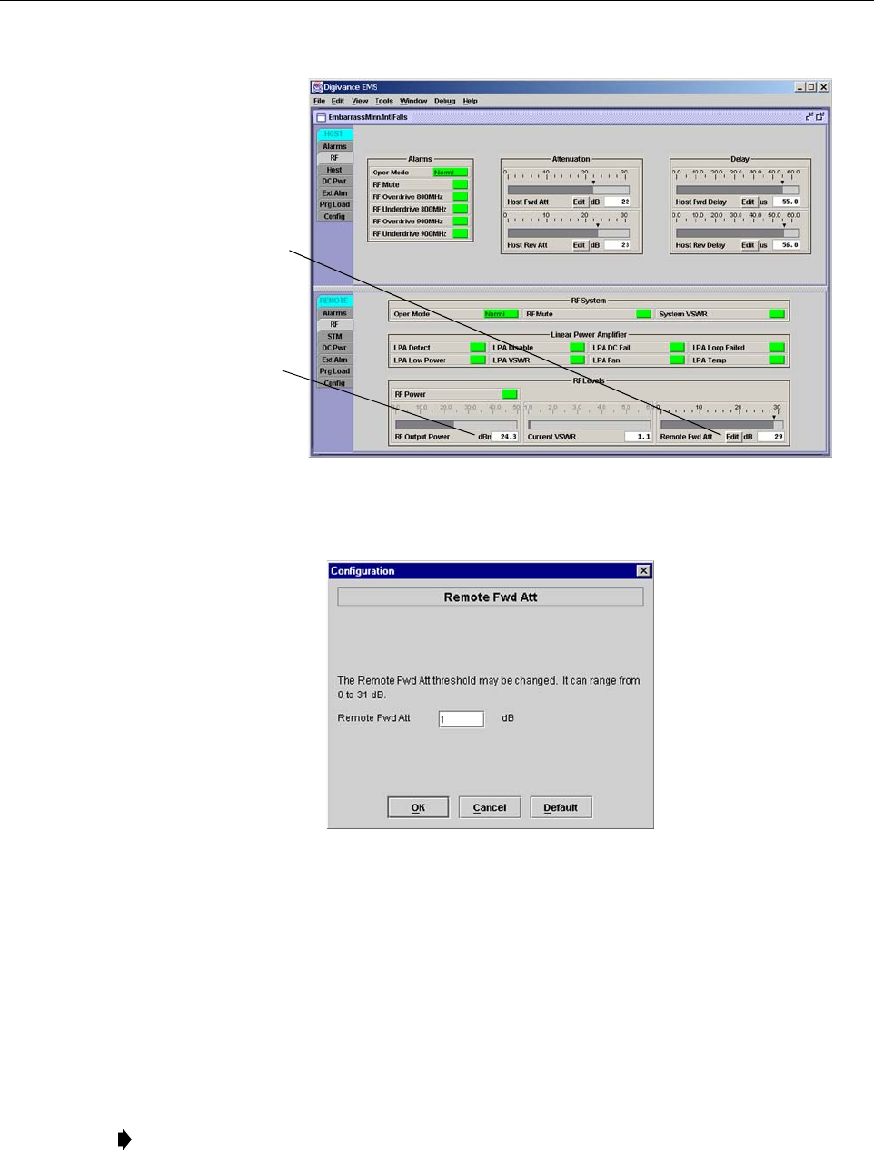
ADCP-75-187 • Issue 3 • September 2006 • Section 3: OPERATION
Page 3-14
© 2006, ADC Telecommunications, Inc.
Figure 3-9. Typical REMOTE LPA Display
Figure 3-10. Remote Fwd Att Pop-Up Screen
5. Enter the required attenuation value and click OK to close the pop-up screen and to make
the changes take effect.
6. Verify that the appropriate RF output signal level appears in the RF Output Power field
(see Figure 3-9). This is primarily a reference value and should not take the place of
external test equipment when determining the power level of the composite RF output
signal. Depending on the modulation type and number of channels, the EMS software may
report a power level that is higher or lower (± 3 dB) than the actual RF output signal.
Note: To comply with Maximum Permissible Exposure (MPE) requirements, the
maximum composite output from the antenna cannot exceed 1000 Watts EIRP and the
antenna must be permanently installed in a fixed location that provides at least 6 meters
(20 feet) of separation from all persons.
Click Edit button to
open the Remote Fwd
Att pop-up screen
RF output signal
level (± 3 dB)
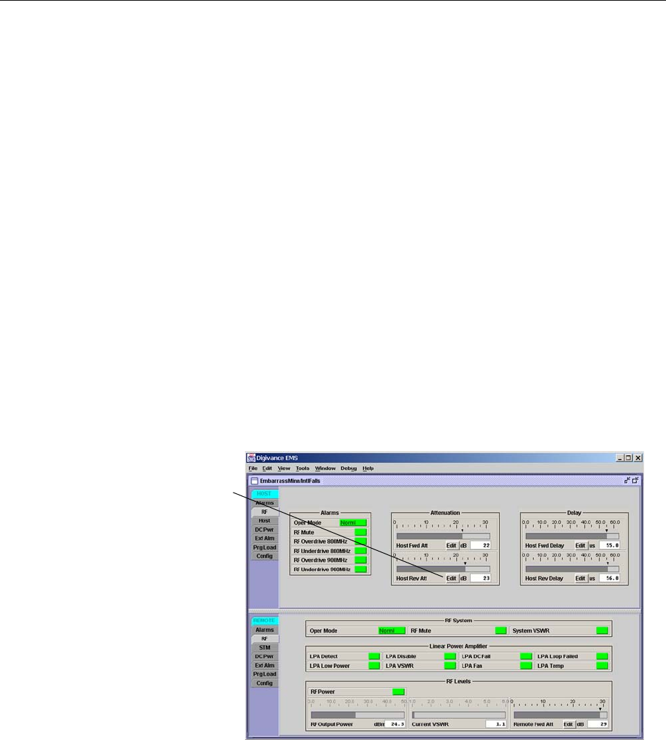
ADCP-75-187 • Issue 3 • September 2006 • Section 3: OPERATION
Page 3-15
© 2006, ADC Telecommunications, Inc.
2.6 Reference Procedure: Enter Host Reverse Attenuation
The level of the RF signal that should be input to the EBTS will vary depending on the type of
EBTS, the receive distribution, and the number of channels present. To interface with the EBTS,
the reverse path signal level must be adjusted to provide the signal level required at the EBTS
input port(s). The HU provides from –1 to +30 dB of gain in the reverse path. By default, the
host reverse attenuator is set to –31 dB of attenuation which provides –1 dB of gain. Use the
following procedure to set the reverse path gain:
1. Check the EBTS manufacturer’s specifications to determine the composite signal level
required at the reverse path input port(s). Note that 800/900 MHz SMR host units have two
reverse path input ports.
2. Determine the overall gain and loss imposed on the signal by the antenna, antenna cable,
and by the cables that connect the HU to the EBTS.
3. Determine the amount of gain required to raise the reverse path signal to the level required
at the EBTS.
4. Click on the HOST RF tab. The HOST RF display will open within the EMS main
window as shown in Figure 3-11.
Figure 3-11. Typical HOST RF Display
5. Click on the Host Rev Att field Edit button (see Figure 3-11). The Host Rev Att pop-up
screen will open as shown in Figure 3-12.
Click Edit button to
open the Host Rev Att
pop-up screen
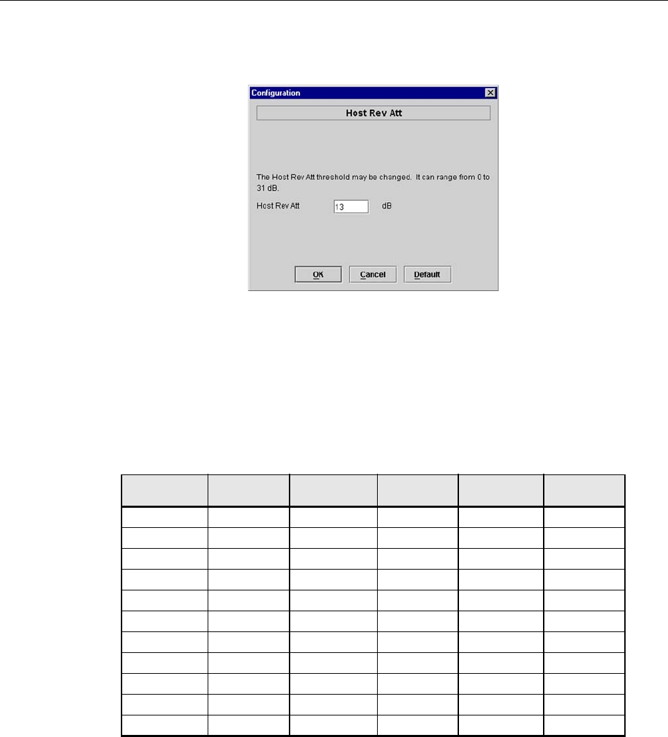
ADCP-75-187 • Issue 3 • September 2006 • Section 3: OPERATION
Page 3-16
© 2006, ADC Telecommunications, Inc.
Figure 3-12. Host Rev Att Pop-Up Screen
6. Enter the attenuation value that will provide the required gain. Refer to Table 3-2 for the
attenuation values and the corresponding gain (nominal) values.
7. Click OK to close the pop-up screen and to make the changes take effect.
2.7 Reference Procedure: Enter Host Forward and Reverse Delay
The forward and reverse delay function allows entry of from 0 to 63 μsec of delay in the
forward and reverse paths. This feature is used when multiple systems are used to transport the
same channel and there is a significant difference in the path delay between systems. Additional
delay may be entered to balance the overall system delay. The amount of delay required must be
calculated by the RF engineer and should be included in the system design plan. The default
setting is 0 μsec. Use the following procedure to change the forward and reverse path delay:
Table 3-2. Reverse Path Attenuation Setting and Nominal Gain Provided
ATTENUATION
SETTING
GAIN
PROVIDED
ATTENUATION
SETTING
GAIN
PROVIDED
ATTENUATION
SETTING
GAIN
PROVIDED
0 dB →30 dB 11 dB →19 dB 22 dB →8 dB
1 dB 29 dB 12 dB 18 dB 23 dB 7 dB
2 dB 28 dB 13 dB 17 dB 24 dB 6 dB
3 dB 27 dB 14 dB 16 dB 25 dB 5 dB
4 dB 26 dB 15 dB 15 dB 26 dB 4 dB
5 dB 25 dB 16 dB 14 dB 27 dB 3 dB
6 dB 24 dB 17 dB 13 dB 28 dB 2 dB
7 dB 23 dB 18 dB 12 dB 29 dB 1 dB
8 dB 22 dB 19 dB 11 dB 30 dB 0 dB
9 dB 21 dB 20 dB 10 dB 31 dB –1 dB
10 dB 20 dB 21 9 dB
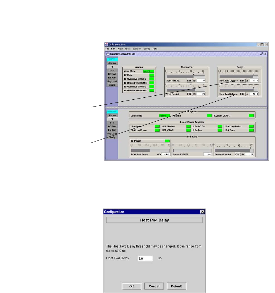
ADCP-75-187 • Issue 3 • September 2006 • Section 3: OPERATION
Page 3-17
© 2006, ADC Telecommunications, Inc.
1. Click on the HOST RF tab. The HOST RF display will open within the EMS main
window as shown in Figure 3-13.
Figure 3-13. Typical HOST RF Display
2. Click on the Host Fwd Delay field Edit button (see Figure 3-13). The Host Fwd Delay
pop-up screen will open as shown in Figure 3-14.
Figure 3-14. Host Fwd Delay Pop-Up Screen
3. Obtain the value of the forward delay as specified in the system design plan. The delay is
adjustable in 0.1 μsec steps.
4. Enter the forward path delay value and click OK to close the pop-up screen and to make
the changes take effect.
5. Repeat the process for reverse delay by right-clicking on the appropriate delay section (see
Figure 3-13) and then entering the required delay value in the pop-up screen.
6. Click OK to close each pop-up screen and to make the changes take effect.
Click Edit button to
open the Host Fwd
Delay pop-up screen
Click Edit button to
open the Host Rev
Delay pop-up screen

ADCP-75-187 • Issue 3 • September 2006 • Section 3: OPERATION
Page 3-18
© 2006, ADC Telecommunications, Inc.
Blank

ADCP-75-187 • Issue 3 • September 2006 • Section 4: MAINTENANCE
Page 4-1
© 2006, ADC Telecommunications, Inc.
SECTION 4: MAINTENANCE
1 SYSTEM MAINTENANCE OVERVIEW . . . . . . . . . . . . . . . . . . . . . . . . . . . . . . . . . . . . . . . . . . . . . . . . . . . . . . . . . .4-1
1.1 Tools and Materials . . . . . . . . . . . . . . . . . . . . . . . . . . . . . . . . . . . . . . . . . . . . . . . . . . . . . . . . . . . . . . .4-1
2 FAULT DETECTION AND ALARM REPORTING . . . . . . . . . . . . . . . . . . . . . . . . . . . . . . . . . . . . . . . . . . . . . . . . . . . .4-2
3 FAULT ISOLATION AND TROUBLESHOOTING . . . . . . . . . . . . . . . . . . . . . . . . . . . . . . . . . . . . . . . . . . . . . . . . . . . .4-4
3.1 Host Unit Troubleshooting. . . . . . . . . . . . . . . . . . . . . . . . . . . . . . . . . . . . . . . . . . . . . . . . . . . . . . . . . . .4-5
3.2 RU Troubleshooting . . . . . . . . . . . . . . . . . . . . . . . . . . . . . . . . . . . . . . . . . . . . . . . . . . . . . . . . . . . . . . .4-7
4 TEST PROCEDURES . . . . . . . . . . . . . . . . . . . . . . . . . . . . . . . . . . . . . . . . . . . . . . . . . . . . . . . . . . . . . . . . . . . . 4-11
4.1 Optical Power Test. . . . . . . . . . . . . . . . . . . . . . . . . . . . . . . . . . . . . . . . . . . . . . . . . . . . . . . . . . . . . . . 4-11
4.2 Optical Loopback Test . . . . . . . . . . . . . . . . . . . . . . . . . . . . . . . . . . . . . . . . . . . . . . . . . . . . . . . . . . . . 4-13
5 SCHEDULED MAINTENANCE REQUIREMENTS . . . . . . . . . . . . . . . . . . . . . . . . . . . . . . . . . . . . . . . . . . . . . . . . . . 4-14
_________________________________________________________________________________________________________
1 SYSTEM MAINTENANCE OVERVIEW
This section explains the Digivance system fault detection and alarm reporting system, provides
a method for isolating and troubleshooting faults, and provides test procedures. The Digivance
system requires minimal regular maintenance to insure continuous and satisfactory operation.
The only components that require regular replacement are the HU cooling fans.
Maintenance also includes diagnosing and correcting service problems as they occur. When an
alarm is reported, it will be necessary to follow a systematic troubleshooting procedure to locate
the problem. Once the source of the problem is isolated, the appropriate corrective action can be
taken to restore service. The only internal components that can be replaced are the cooling fans
that mount in the HU. The failure of any other internal component will require replacement of
the entire unit.
1.1 Tools and Materials
The following tools and materials are required in order to complete the maintenance procedures
specified in this section:
• IR filtering safety glasses
• Patch cords with SC connectors
• 15 dB in-line SC optical attenuators
• Optical power meter (1550 and 1310 nm)
Content Page

ADCP-75-187 • Issue 3 • September 2006 • Section 4: MAINTENANCE
Page 4-2
© 2006, ADC Telecommunications, Inc.
2 FAULT DETECTION AND ALARM REPORTING
The Digivance LRCS on-board embedded software detects various unit and system faults which
generate either a Major or Minor alarm. A Major alarm indicates that the system has failed in a
way that directly affects RF transport performance. When a major alarm occurs, all RF
functions are disabled and the system is out of service. A Minor alarm means that system
performance is not affected or in some cases, that the performance may no longer be optimal.
When a minor alarm occurs, RF functions continue and the system remains in service.
The following means are used to report Major and Minor alarms:
• HU alarm contacts
• HU and RU LED’s
• EMS software Graphical User Interface (GUI)
• Network Operations Center - Network Element Manager (NOC/NEM) interface
• SNMP interface
The HU is equipped with a set of both normally open (NO) and normally closed (NC) alarm
contacts which may be used to report both Major and Minor alarms to an external alarm system.
The alarm contacts summarize the inputs so that any Major or Minor alarm will trigger an alarm
report to the external alarm system.
The HU is equipped with multiple front panel LED indicators that show status and alarm
information by displaying various colors: Green, Red, Yellow, and Off. The RU is equipped
with a single LED indicator that shows status and alarm information by displaying either Red or
Off. A detailed description of the Host Unit and Remote Unit LED indicators is provided
respectively in Table 4-1 and Table 4-2.
The EMS software GUI provides both a summary and a detailed list of alarm information that
includes unit and module level faults, circuit faults, and measured value faults such as voltages,
RF power, and temperature. A summary showing a list of all systems and their current alarm
status is presented through the Alarm OverView display. A more detailed list of alarm
information is presented through the HOST alarm display and the REMOTE alarm display. The
various fault conditions that trigger a major or minor alarm report are shown in the HOST and
REMOTE alarm displays.
The NOC/NEM interface provides the same summary and detailed listing of alarm information
as the EMS software GUI but in an ASCII text string format. Sending the command GET
ALARMSUMMARY produces a list of all systems and their current alarm status. Sending the
command GET ALARM ALL for a specific system will produce a detailed list of alarm
information for the specified system.
The SNMP interface provides alarm information to up to ten SNMP managers which must be
registered with the SNMP agent. The SNMP interface allows the SNMP managers to receive the
alarm and status information generated by the host and remote units. The presentation of the
alarm information is dependent on the features of the SNMP manager.

ADCP-75-187 • Issue 3 • September 2006 • Section 4: MAINTENANCE
Page 4-3
© 2006, ADC Telecommunications, Inc.
Table 4-1. Host Unit LED Indicators
INDICATOR COLOR DESCRIPTION
POWER
Green
Off
Indicates if the HU is powered or un-powered.
The DC power source is on.
The DC power source is off.
STANDBY
Green (blinking)
Yellow (blinking)
Red (blinking)
Off
Indicates if the system is in the standby, normal, test, or
program load mode.
The HU is in the standby mode.
The HU is in the program load mode.
The HU is in the test mode.
The HU is in the normal mode.
HOST UNIT
Green
Ye l l ow
Red
Indicates if the HU is normal, over temperature, if an
internal fault is detected, or if there is an equipment mis-
match.
The HU is normal.
The HU is over temperature or detects an internal fault.
The HU detects an internal fault or HU/RU band mismatch.
REMOTE UNIT
Green
Ye l l ow
Red
Indicates if an alarm is detected at the RU.
No alarms detected at the RU.
A minor alarm is detected at the RU.
A major alarm is detected at the RU.
DRIVE 851–869
DRIVE 935–940
(Rear Access HU)
DRIVE
(Front Access HU)
Green
Ye l l ow
Red
Indicates if the specified forward path RF signal level is
normal, above overdrive threshold, or below underdrive
threshold.
The RF signal level is normal
The RF signal level is below the underdrive threshold.
The RF signal level is above the overdrive threshold.
FWD/REV
(PORT 1/PORT 2)
Green
Red
Indicates if the reverse path optical signals from the RU
are normal, if optical signal errors are detected, or if the
optical signal is not detected.
The reverse path optical signals are normal.
Excessive errors (see Note) are detected in the reverse path
optical signals or the HU is not receiving a reverse path optical
signal.
Note: Excessive errors means the Bit Error Rate (BER) has exceeded 10–6 (1 bit error per million bits).
Table 4-2. Remote Unit LED Indicator
INDICATOR COLOR DESCRIPTION
STATUS
Off
Red
Indicates if the RU is unpowered, normal, if optical signal
errors are detected, if the optical signal is not detected, or
if an internal fault is detected.
The RU is unpowered or the RU is normal and no faults are
detected.
The RU detects an internal fault, excessive errors (see Note)
are detected in the forward path optical signals, or the RU is
not receiving a forward path optical signal.
Note: Excessive errors means the Bit Error Rate (BER) has exceeded 10–6 (1 bit error per million bits).
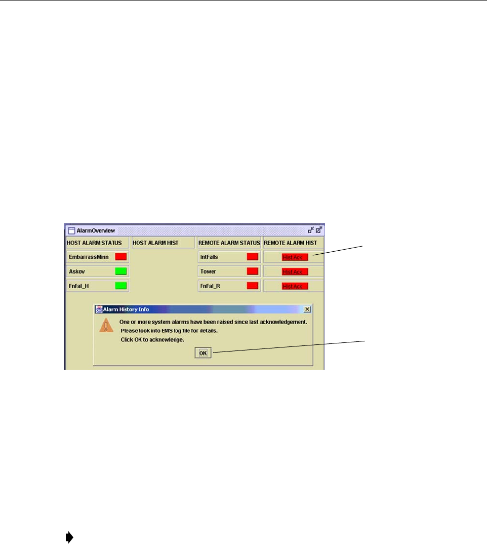
ADCP-75-187 • Issue 3 • September 2006 • Section 4: MAINTENANCE
Page 4-4
© 2006, ADC Telecommunications, Inc.
3 FAULT ISOLATION AND TROUBLESHOOTING
Alarm information may be accessed using the HU and RU LED indicators, the EMS software
GUI, the NOC-NEM interface, or the SNMP manager. When an alarm occurs, use the unit LED
indicator(s) and any one of the specified software tools to determine which Digivance system is
affected, which unit (HU or RU) reported the alarm, and the fault that generated the alarm. Then
refer to either Section 3.1 Host Unit Troubleshooting or Section 3.2 RU Troubleshooting to
isolate the problem and to determine the corrective action required.
When attempting to isolate a problem, always determine the initial fault that generated the
alarm report. Some faults may cause additional faults to be reported which tends to obscure the
initial reason for the alarm. To help isolate faults, the EMS GUI provides an AlarmOverview
screen, shown in Figure 4-1, that indicates which Digivance system/unit is reporting the alarm.
Figure 4-1. AlarmOverView Screen
The AlarmOverview screen includes an ALARM HIST indicator which the user should click to
acknowledge that an alarm exists. Acknowledging the alarm opens the Alarm History Info
dialog box (also shown in Figure 4-1) which directs the user to view the EMS Log file for
details. The EMS Log file lists the various faults in the order in which they occurred. Clear each
fault starting with the initial fault. In most instances, clearing the initial fault will also clear any
remaining faults. For additional information on using the AlarmOverview screen, refer to the
Digivance Element Management System User Manual (see Related Publications section).
Note: It is recommended that if there are alarms at both the HU and RU, the optical faults
should be checked and cleared first. Because the HU and RU function as a system, a fault
in the fiber optic link will cause alarms to be reported by both the HU and RU.
Click to acknowledge
alarm and to open Alarm
History Info dialog box
Click to clear alarm
history fault indicator
and to close Alarm
History Info dialog box

ADCP-75-187 • Issue 3 • September 2006 • Section 4: MAINTENANCE
Page 4-5
© 2006, ADC Telecommunications, Inc.
3.1 Host Unit Troubleshooting
Use this section to troubleshoot alarms that originate with the Host Unit. When a Minor alarm
occurs, one (or more) of the Host Unit LED’s will turn yellow and the EMS software will indicate
a minor fault/alarm. When a Major alarm occurs, one (or more) of the Host Unit LED’s will turn
red and the EMS software will report a major fault/alarm. Locate the LED and the corresponding
software fault/status indicator in Table 4-3 and then take the corrective action indicated.
Table 4-3. Host Unit Fault/Alarm Isolation Diagram
Power
Host Unit Front Panel LED
Standby
Host
Unit
Green - Normal
Yellow - Minor Alarm
Red - Major Alarm
Green - Powered
Off - Not powered
Green blinking - Standby
Yellow blinking -
Program load
Red blinking - Test
Off - Normal
Temperature - Over temperature
Fwd Synth Lock - Forward
synthesizer out of lock
LO Synth Lock - Local
oscillator synthesizer out of lock
Pri Rev Synth Lock - Reverse
primary synthesizer out of lock
8 Volt - Onboard 8 Volt power
supply below threshold
3.8 Volt - Onboard 3.8 Volt power
supply below threshold
Pri Fwd Mux Lock - Forward primary
phase locked loop out-of-lock
Pri Laser Fail - Forward primary
laser failure
Hardware mismatch - Host and
Remote band mismatch
Reverse Link Fault
Software Fault/Status Indicator
Replace HU
Table 4-4
Problem G
Table 4-4
Problem B
Replace HU or
RU with
correct unit
Corrective Action
or Reference
Oper Mode - Operational
mode of system
No specific HU faults - Only
faults with no associated LED
are displayed
Table 4-4
Problem A
Use EMS to
change system to
required mode
Continued
20013-B
Remote
Unit
Green - Normal
Yellow - Minor Alarm at Remote Unit - See Table 4-5. Remote Unit Fault/Alarm Isolation Diagram
Red - Major Alarm at Remote Unit - See Table 4-5. Remote Unit Fault/Alarm Isolation Diagram
ADCP-75-187 • Issue 3 • September 2006 • Section 4: MAINTENANCE
Page 4-6
© 2006, ADC Telecommunications, Inc.
Table 4-4. Host Unit Fault/Alarm Corrective Action
PROBLEM A: The HU is not powered.
POSSIBLE CAUSE CORRECTIVE ACTION/COMMENTS
1. The HU is turned off.
2. The fuse is open/removed from the fuse panel
or the DC power has failed.
1. Place On/Off switch in the On position.
2. Check DC power source, repair as needed, and
replace or reinstall fuse at fuse panel.
PROBLEM B: The HU is overheating.
POSSIBLE CAUSE CORRECTIVE ACTION/COMMENTS
1. Air intake or exhaust opening to HU chassis
is blocked
2. Ambient temperature > 50º C/122º F.
3. Faulty fan.
4. The HU has failed.
1. Remove cause of air-flow blockage.
2. Reduce ambient temperature.
3. Replace HU fan (See applicable manual).
4. Replace HU.
Host Unit Front Panel LED Software Fault/Status Indicator Corrective Action
or Reference
Table 4-3. Host Unit Fault/Alarm Isolation Diagram, continued
Fwd/Rev
(Port 1/Port 2)
See Table 4-4
Problem E
See Table 4-4
Problem E
Green - Normal
Red - Major Alarm
Pri Rx Light - No light received
over optical reverse path
Pri Rx Errors - Excessive errors
received over optical reverse path
See specific
fault indicator
See specific
fault indiator
Minor Contact Output - Minor alarm
reported by HU or STM
Major Contact Output - Major alarm
reported by HU or STM
Remote Lost - The HU cannot
communicate with remote (STM)
EMS Link Status - The EMS cannot
communicate with HU
No Associated LED
See Table 4-4
Problem E
See Table 4-4
Problem F
20583-A
Drive
851-869
(REAR
ACCESS)
Green - Normal
Yellow - Minor Alarm
Red - Major Alarm
RF Underdrive 800 MHz - 800 MHz
forward path RF signal level too low
RF Overdrive 800 MHz - 800 MHz
forward path RF signal level too high
Table 4-4
Problem C
Table 4-4
Problem D
Drive
935-940
(REAR
ACCESS)
Green - Normal
Yellow - Minor Alarm
Red - Major Alarm
RF Underdrive 900 MHz - 900 MHz
forward path RF signal level too low
RF Overdrive 900 MHz - 900 MHz
forward path RF signal level too high
Table 4-4
Problem C
Table 4-4
Problem D
Drive
(FRONT
ACCESS)
Green - Normal
Yellow - Minor Alarm
Red - Major Alarm
RF Underdrive - Forward path
RF signal level too low
RF Overdrive - Forward path
RF signal level too high
Table 4-4
Problem C
Table 4-4
Problem D

ADCP-75-187 • Issue 3 • September 2006 • Section 4: MAINTENANCE
Page 4-7
© 2006, ADC Telecommunications, Inc.
3.2 RU Troubleshooting
Use this section to troubleshoot alarms that originate with the RU. When a Minor or Major
alarm occurs, the RU STATUS LED will turn red and the EMS software will indicate a minor or
major fault/alarm. Use the EMS software to identify the fault and then refer to Table 4-5 to
determine the corrective action required.
PROBLEM C: The RF input signal level is below the underdrive threshold.
POSSIBLE CAUSE CORRECTIVE ACTION/COMMENTS
1. Composite output signal from EBTS is too low.
2. Faulty coaxial connection between the HU
and the EBTS.
3. Incorrect attenuation in forward path RF
coaxial link.
1. Check EBTS composite output signal level and
adjust if too low.
2. Correct EBTS cables if faulty.
3. Check Host Forward Attenuator setting and
adjust if attenuation is too high.
PROBLEM D: The RF input signal is above the overdrive threshold.
POSSIBLE CAUSE CORRECTIVE ACTION/COMMENTS
1. Composite output signal level from EBTS is
too high.
2. Incorrect attenuation in forward path RF
coaxial link.
1. Check EBTS composite output signal level and
adjust if too high.
2. Check Forward Attenuator setting and adjust if
attenuation is too low.
PROBLEM E: No light received over the reverse path or excessive errors received over the reverse path
POSSIBLE CAUSE CORRECTIVE ACTION/COMMENTS
1. Faulty reverse path optical fiber.
2. Faulty optical transmit port at the RU;
or faulty optical receive port at the HU
1. Test optical fiber. Clean connector if dirty. Repair
or replace optical fiber if faulty. (See Section 4.1).
2. Test optical ports. Replace HU or RU if port is
faulty (See Section 4.2).
PROBLEM F: The HU does not respond to control or monitoring commands sent by the EMS.
POSSIBLE CAUSE CORRECTIVE ACTION/COMMENTS
1. The HU is not powered.
2. The cable connection between the HU and the
EMS computer is faulty.
3. The CAN cable connections between the HUs
in a multiple HU installation are faulty.
1. See Problem A this table.
2. Inspect EMS cable and repair or replace if faulty.
3. Inspect each CAN cable and repair or replace if
faulty.
PROBLEM G: There is a loss of gain in either the primary or diversity reverse path of 10 dBm or greater.
POSSIBLE CAUSE CORRECTIVE ACTION/COMMENTS
1. The HU has failed.
2. The RU has failed
1. Replace the HU.
2. Replace the RU.
Table 4-4. Host Unit Fault/Alarm Corrective Action, continued

ADCP-75-187 • Issue 3 • September 2006 • Section 4: MAINTENANCE
Page 4-8
© 2006, ADC Telecommunications, Inc.
Table 4-5. Remote Unit Fault/Alarm Isolation Diagram
Remote Unit LED Software Fault/Status Indicator
Off - Not powered or Normal
No Response for
Minor Alarm
Red - Major Alarm
Temperature - Over temperature
Replace RU
See Table 4-6
Problem A
Corrective Action
or Reference
Converter - Power supply
converter failure
LO Synth Lock - Local
oscillator synthesizer out of lock
Fwd Synth Lock - Forward
synthesizer out of lock
Pri Rev Synth Lock - Reverse
primary synthesizer out of lock
Ref Synth Lock - Reference
synthesizer out of lock
8 Volt - Onboard 8 Volt power
supply below threshold
3.8 Volt - Onboard 3.8 Volt power
supply below threshold
Pri Rev Mux Lock - Reverse primary
phase locked loop out-of-lock
Pri Laser Fail - Reverse primary
laser failure
LPA DC Fail - LPA
power supply failure
LPA Loop Fail - LPA
internal loop failure
LPA Low Power - LPA
internal amplifier failure
Continued 20584-B
See Table 4-6
Problem E
See Table 4-6
Problem E
See Table 4-6
Problem C
See Table 4-6
Problem B
See Table 4-6
Problem A
See Table 4-6
Problem D
Replace HU or
RU with
correct unit
LPA Temp - LPA over
temperature
LPA Over Power - LPA
signal level too high
LPA VSWR - The LPA
VSWR is too high
System VSWR - The VSWR at
the quadraplexer is too high
Pri Rx Light - No light received
over optical forward path
Pri Errors - Excessive errors
received over optical forward path
Hardware mismatch - Host and
Remote band mismatch
One LED, no
designation

ADCP-75-187 • Issue 3 • September 2006 • Section 4: MAINTENANCE
Page 4-9
© 2006, ADC Telecommunications, Inc.
Table 4-6. Remote Unit Fault/Alarm Corrective Action
PROBLEM A: The RU (STM or LPA) is overheating.
POSSIBLE CAUSE CORRECTIVE ACTION/COMMENTS
1. Debris preventing air from freely circulating
around the RU aluminum enclosure.
2. Ambient temperature > 50º C/122º F.
3. The RU has failed.
1. Remove cause of air-flow blockage.
2. Reduce ambient temperature.
3. Replace RU.
PROBLEM B: The output power from the LPA exceeds the maximum rating.
POSSIBLE CAUSE CORRECTIVE ACTION/COMMENTS
1. The power level of the RF forward path
composite input signal at the HU is too high.
2. The RU (LPA) has failed.
1. Check the power level of the RF composite input
signal at the HU and adjust to correct level. To
reset, use EMS to place Digivance system in
standby mode and then place system back in
normal mode.
2. Replace RU.
PROBLEM C: The VSWR at the LPA exceeds the threshold setting of 3:1.
POSSIBLE CAUSE CORRECTIVE ACTION/COMMENTS
1. The antenna cable or antenna cable connectors
are faulty.
2. The antenna or antenna system is faulty.
3.The RU qudraplexer or LPA has failed.
1. Inspect antenna cable and connectors and repair
or replace as needed.To reset, use EMS to place
Digivance system in standby mode and then place
system back in normal mode.
2. Check the antenna circuit for shorts or opens
(including lightning protector). To reset, use EMS
to place Digivance system in standby mode and
then place system back in normal mode.
3. Replace RU.
Remote Unit LED Software Fault/Status Indicator Corrective Action
or Reference
Host Lost - The STM cannot
communicate with Host (HU)
EMS Link Status - The EMS cannot
communicate with STM
RF Power - No RF power detected
at quadraplexer (STM)
LPA Disable - The LPA is shut down
No Associated LED See Table 4-6
Problem G
See Table 4-6
Problem F
See Table 4-6
Problem E
See Table 4-6
Problem H
Table 4-5. Remote Unit Fault/Alarm Isolation Diagram, continued
20585-A

ADCP-75-187 • Issue 3 • September 2006 • Section 4: MAINTENANCE
Page 4-10
© 2006, ADC Telecommunications, Inc.
PROBLEM D: The forward path VSWR is above threshold.
POSSIBLE CAUSE CORRECTIVE ACTION/COMMENTS
1. Faulty antenna or antenna system.
2. Faulty antenna cable.
3. The RU qudraplexer has failed.
1. Check the antenna system for shorts or opens
(including lightning protector). To reset, use
EMS to place Digivance system in standby mode
and then place system back in normal mode.
2. Check the antenna cable for faulty connections.
3. Replace the RU.
PROBLEM E: No light received over the forward path or excessive errors received over the forward path
POSSIBLE CAUSE CORRECTIVE ACTION/COMMENTS
1. Faulty forward path optical fiber.
2. Faulty optical transmit port at the HU;
or faulty optical receive port at the RU.
1. Test optical fiber. Clean connector if dirty. Repair
or replace optical fiber if faulty. (See Section 4.1).
2. Test optical ports. Replace HU or RU if port is
faulty (see Section 4.2).
PROBLEM F: The RU does not respond to control or monitoring commands sent by the EMS.
POSSIBLE CAUSE CORRECTIVE ACTION/COMMENTS
1. The cable connection between the HU and
the EMS computer is faulty.
1. Inspect EMS cable and repair or replace if faulty.
PROBLEM G: No RF power is detected at the RU quadraplexer.
POSSIBLE CAUSE CORRECTIVE ACTION/COMMENTS
1. No RF power is being input to the HU or the
RF input signal level at the HU is too low.
2. The RU (LPA) is faulty.
1. Check the RF input power level at the HU and
adjust until within specifications.
2. Replace RU.
PROBLEM H: The RF output form the RU (LPA) is shut down.
POSSIBLE CAUSE CORRECTIVE ACTION/COMMENTS
1. The LPA is in the forced shutdown mode.
2. The RU (LPA) is faulty.
1. Check for fault conditions that will cause a major
alarm. Correct faults as required. To reset, use
EMS to place Digivance system in standby mode
and then place system back in normal mode
2. Replace RU.
Table 4-6. Remote Unit Fault/Alarm Corrective Action, continued
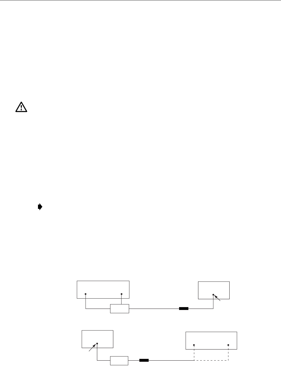
ADCP-75-187 • Issue 3 • September 2006 • Section 4: MAINTENANCE
Page 4-11
© 2006, ADC Telecommunications, Inc.
4 TEST PROCEDURES
This section provides procedures for common troubleshooting and maintenance tests. Refer to
these procedures as needed when specified in the Fault/Alarm Isolation Diagrams in Section 3.
4.1 Optical Power Test
A break in an optical fiber or a fault with the optical connector will interrupt communications
between linked components or generate excessive errors. Use the following procedure to isolate
a problem with an optical fiber or connector.
1. Put on the IR filtering safety glasses.
2. Notify the NOC or alarm monitoring system operator that the system is going offline.
3. At the HU, place the On/Off switch in the OFF position (press O). At the RU, place the
AC circuit breaker switch in the open (OFF) position.
4. Disconnect the optical fiber connectors for the fiber to be tested at the HU and the RU.
5. Inspect the optical connectors. Verify that connectors are clean and that no scratches or
imperfections are visible on the fiber end. Clean and polish the optical connectors if necessary.
6. Connect the optical power meter to the output (receiver) end of the optical fiber as shown
in Figure 4-2. If an attenuator was included in the fiber link, make sure it is installed.
Figure 4-2. Forward and Reverse Path Optical Fiber Test Set Up
Danger: This equipment uses a Class 1 Laser according to FDA/CDRH rules. Laser radiation
can seriously damage the retina of the eye. Do not look into the ends of any optical fiber. Do not
look directly into the optical transmitter of any unit or exposure to laser radiation may result.
An optical power meter should be used to verify active fibers. A protective cap or hood MUST
be immediately placed over any radiating transmitter or optical fiber connector to avoid the
potential of dangerous amounts of radiation exposure. This practice also prevents dirt particles
from entering the connector.
Note: Turning off the HU and RU disables the respective lasers which is necessary in
order to safely inspect and clean the optical connectors.
HOST UNIT
FWD
(PORT 1)
REV
(PORT 2)
BAND 2 BAND 1
ATTENUATOR
(IF USED)
ATTENUATOR
(IF USED)
FWD/REV PATH
OPTICAL FIBER
FWD/REV PATH
OPTICAL FIBER
-15 TO -25 dBm
-15 TO -25 dBm
FORWARD PATH OPTICAL FIBER
TEST SET UP
REVERSE PATH
OPTICAL FIBER TEST SET UP
20979-A
REMOTE UNIT
OPTICAL POWER
METER
OPTICAL POWER
METER
WDM
WDM
23
3
BAND 1 = LOWER FREQUENCY SYSTEM
BAND 2 = HIGHER FREQUENCY SYSTEM
ADCP-75-187 • Issue 3 • September 2006 • Section 4: MAINTENANCE
Page 4-12
© 2006, ADC Telecommunications, Inc.
7. Connect the input (transmitter) end of the optical fiber to the transmitting HU or RU.
8. If the transmitting unit is the HU, place the On/Off switch in the ON position (press I). If
the transmitting unit is the RU, close (turn on) the AC circuit breaker switch.
9. Using the transmitting HU or RU as an optical light source, measure the optical power at
the receiver end of the optical fiber. The power level of the optical signal received at the
HU or RU should be –15 to –25 dBm (with attenuator installed). If the power level of the
received optical signal is within this range, the optical fiber and the far end unit are good.
If the power level of the signal is greater than –15 dBm, insert additional attenuation to
bring the signal level within the specified range. If the power level is less than –25 dBm,
the value of the external attenuator is too high, the optical fiber is faulty, or the far end unit
optical transmitter is faulty. Continue with test procedure to isolate the problem
10. If the transmitting unit is the HU, place the On/Off switch in the OFF position (press O).
If the transmitting unit is the RU, open (turn off) the AC circuit breaker switch.
11. Disconnect the optical power meter from the receiver end of the optical fiber.
12. Use a 1 meter patch cord to connect the optical power meter to the transmitting HU or
RU as shown in Figure 4-3.
Figure 4-3. Host Unit and Remote Unit Optical Transmitter Test Set Up
13. If the transmitting unit is the HU, place the On/Off switch in the ON position (press I). If
the transmitting unit is the RU, close (turn on) the AC circuit breaker switch.
14. Measure the optical output power of the transmitting HU or RU. The power level of the
optical output signal from the HU or RU must meet the following specification:
Forward Path Signal at the HU: 0 + 1 dBm
Reverse Path Signal at the RU: +1.3 + 1 dBm
If the power level of the optical output signal is within specifications with a 1 meter patch
cord installed, the fiber optic link is faulty. If the power level of the optical signal is not
within specifications, the far end HU or RU optical transmitter is faulty.
Caution: Erratic operation may occur with an optical input signal level of –13 dBm or higher.
If the optical input signal level exceeds –9 dBm, the optical receiver may be damaged.
HOST UNIT
REMOTE UNIT
+1.3 +/- 1 dBm
0 +/- 1 dBm
HOST UNIT OPTICAL TRANSMITTER
TEST SET UP
REMOTE UNIT OPTICAL TRANSMITTER
TEST SET UP
1 METER PATCH CORD
1 METER PATCH CORD 20980-A
FWD
(PORT 1)
REV
(PORT 2)
BAND 2 BAND 1
OPTICAL POWER
METER
OPTICAL POWER
METER
BAND 1 = LOWER FREQUENCY SYSTEM
BAND 2 = HIGHER FREQUENCY SYSTEM

ADCP-75-187 • Issue 3 • September 2006 • Section 4: MAINTENANCE
Page 4-13
© 2006, ADC Telecommunications, Inc.
15. If the transmitting unit is the HU, place the On/Off switch in the OFF position (press O).
If the transmitting unit is the RU, open (turn off) the AC circuit breaker switch.
16. Disconnect the optical power meter from the receiver end of the optical fiber.
17. Reconnect the optical fibers to the receiving HU or RU.
18. Repeat steps 3 through 17 for each optical fiber that requires testing.
19. When ready to put the system back into service, place the On/Off switch on the HU in the
ON position (press I) and close (turn on) the AC circuit breaker switch for the RU.
20. Notify the NOC or alarm monitoring service that the system is going back online.
4.2 Optical Loopback Test
The following procedure provides a test to determine if an optical port fault exists with the Host
Unit.
1. Put on the IR filtering safety glasses.
2. Notify the NOC or alarm monitoring system operator that the system is going offline.
3. Place the On/Off switch in the OFF position (press O).
4. Disconnect the optical fiber connectors from the FWD (PORT 1) and REV (PORT 2)
optical ports and place a dust cap over each connector.
5. Plug a 15 dB in-line optical attenuator into the FWD (PORT 1) optical port as shown in
Figure 4-4.
6. Connect a 1 meter patch cord between the optical attenuator and the REV (PORT 2)
optical port.
7. Place the On/Off switch in the ON position (press I).
Note: Because the RU is equipped with a WDM, the optical loopback test cannot be
performed on the RU.
Danger: This equipment uses a Class 1 Laser according to FDA/CDRH rules. Laser radiation
can seriously damage the retina of the eye. Do not look into the ends of any optical fiber. Do not
look directly into the optical transmitter of any unit or exposure to laser radiation may result.
An optical power meter should be used to verify active fibers. A protective cap or hood MUST
be immediately placed over any radiating transmitter or optical fiber connector to avoid the
potential of dangerous amounts of radiation exposure. This practice also prevents dirt particles
from entering the connector.
Caution: The optical receiver can be damaged if the power level of the optical input signal is
too high. To avoid damaging the optical receiver when performing the loopback test, always
install a 15 dB in-line attenuator in the optical receiver circuit.

ADCP-75-187 • Issue 3 • September 2006 • Section 4: MAINTENANCE
Page 4-14
© 2006, ADC Telecommunications, Inc.
Figure 4-4. Host Unit Loopback Test
8. Observe the FWD/REV (PORT 1/PORT 2) LED indicator which will turn either red or
green. If the LED turns red, either the FWD (PORT 1) optical transmitter or the REV
(PORT 2) receiver is faulty. If the LED turns green, both the FWD (PORT 1) and the REV
(PORT 2) optical ports are good.
9. Place the On/Off switch in the OFF position (press O).
10. Remove the dust caps from the optical fiber connectors.
11. Clean each connector (follow connector supplier’s recommendations) and then insert each
connector into the appropriate optical port.
12. When ready to put the HU back into service, place the On/Off switch in the ON position
(press I).
13. Notify the NOC or alarm monitoring service that the system is going back online.
5 SCHEDULED MAINTENANCE REQUIREMENTS
The only scheduled maintenance required for the SCS system is to remove and replace the HU
cooling fans. This should be done at 60 month intervals. Refer to the applicable Digivance
LRCS Host Unit Installation and Maintenance Manual (See Related Publications section) for
the procedure.
HOST UNIT
1 METER PATCH CORD
15 dB
ATTENUATOR
20019-C
FWD
(PORT 1)
REV
(PORT 2)

ADCP-75-187 • Issue 3 • September 2006 • Section 5: GENERAL INFORMATION
Page 5-1
© 2006, ADC Telecommunications, Inc.
SECTION 5: GENERAL INFORMATION
1 WARRANTY/SOFTWARE . . . . . . . . . . . . . . . . . . . . . . . . . . . . . . . . . . . . . . . . . . . . . . . . . . . . . . . . . . . . . . . . . .5-1
2 SOFTWARE SERVICE AGREEMENT. . . . . . . . . . . . . . . . . . . . . . . . . . . . . . . . . . . . . . . . . . . . . . . . . . . . . . . . . . .5-1
3 REPAIR/EXCHANGE POLICY . . . . . . . . . . . . . . . . . . . . . . . . . . . . . . . . . . . . . . . . . . . . . . . . . . . . . . . . . . . . . . .5-1
4 REPAIR CHARGES . . . . . . . . . . . . . . . . . . . . . . . . . . . . . . . . . . . . . . . . . . . . . . . . . . . . . . . . . . . . . . . . . . . . . .5-2
5 REPLACEMENT/SPARE PRODUCTS . . . . . . . . . . . . . . . . . . . . . . . . . . . . . . . . . . . . . . . . . . . . . . . . . . . . . . . . . .5-2
6 RETURNED MATERIAL . . . . . . . . . . . . . . . . . . . . . . . . . . . . . . . . . . . . . . . . . . . . . . . . . . . . . . . . . . . . . . . . . . .5-2
7 CUSTOMER INFORMATION AND ASSISTANCE . . . . . . . . . . . . . . . . . . . . . . . . . . . . . . . . . . . . . . . . . . . . . . . . . . .5-3
_________________________________________________________________________________________________________
1 WARRANTY/SOFTWARE
The Product and Software warranty policy and warranty period for all ADC Products is
published in ADC’s Warranty/Software Handbook. Contact the Technical Assistance Center at
1-800-366-3891, extension 73476 (in U.S.A. or Canada) or 952-917-3476 (outside U.S.A. and
Canada) for warranty or software information or for a copy of the Warranty/Software
Handbook.
2 SOFTWARE SERVICE AGREEMENT
ADC software service agreements for some ADC Products are available at a nominal fee.
Contact the Technical Assistance Center at 1-800-366-3891, extension 73476 (in U.S.A. or
Canada) or 952-917-3476 (outside U.S.A. and Canada) for software service agreement
information.
3 REPAIR/EXCHANGE POLICY
All repairs of ADC Products must be done by ADC or an authorized representative. Any
attempt to repair or modify ADC Products without written authorization from ADC voids the
warranty.
If a malfunction cannot be resolved by the normal troubleshooting procedures, call the
Technical Assistance Center at 1-800-366-3891, extension 73476 (in U.S.A. or Canada) or
952-917-3476 (outside U.S.A. and Canada). A telephone consultation can sometimes resolve a
problem without the need to repair or replace the ADC Product.
If, during a telephone consultation, ADC determines the ADC Product needs repair, ADC will
authorize the return of the affected Product for repair and provide a Return Material
Authorization number and complete return shipping instructions. If time is critical, ADC can
arrange to ship the replacement Product immediately. In all cases, the defective Product must be
carefully packaged and returned to ADC.
Content Page

ADCP-75-187 • Issue 3 • September 2006 • Section 5: GENERAL INFORMATION
Page 5-2
© 2006, ADC Telecommunications, Inc.
4 REPAIR CHARGES
If the defect and the necessary repairs are covered by the warranty, and the applicable warranty
period has not expired, the Buyer’s only payment obligation is to pay the shipping cost to return
the defective Product. ADC will repair or replace the Product at no charge and pay the return
shipping charges.
Otherwise, ADC will charge a percentage of the current Customer Product price for the repair
or NTF (No Trouble Found). If an advance replacement is requested, the full price of a new unit
will be charged initially. Upon receipt of the defective Product, ADC will credit Buyer with 20
percent of full price charged for any Product to be Out-of-Warranty. Products must be returned
within thirty (30) days to be eligible for any advance replacement credit. If repairs necessitate a
visit by an ADC representative, ADC will charge the current price of a field visit plus round trip
transportation charges from Minneapolis to the Buyer’s site.
5 REPLACEMENT/SPARE PRODUCTS
Replacement parts, including, but not limited to, button caps and lenses, lamps, fuses, and patch
cords, are available from ADC on a special order basis. Contact the Technical Assistance Center
at 1-800-366-3891, extension 73476 (in U.S.A. or Canada) or 952-917-3476 (outside U.S.A.
and Canada) for additional information.
Spare Products and accessories can be purchased from ADC. Contact Sales Administration at
1-800-366-3891, extension 73000 (in U.S.A. or Canada) or 1-952-938-8080 (outside U.S.A.
and Canada) for a price quote and to place your order.
6 RETURNED MATERIAL
Contact the ADC Product Return Department at 1-800-366-3891, extension 73748 (in U.S.A. or
Canada) or 952-917-3748 (outside U.S.A. and Canada) to obtain a Return Material
Authorization number prior to returning an ADC Product.
All returned Products must have a Return Material Authorization (RMA) number clearly
marked on the outside of the package. The Return Material Authorization number is valid for 90
days from authorization.
Page 5-3
ADCP-75-187 • Issue 3 • September 2006 • Section 5: GENERAL INFORMATION
7 CUSTOMER INFORMATION AND ASSISTANCE
© 2006, ADC Telecommunications, Inc
.
All Rights Reserved
13944-M
WRITE:
ADC TELECOMMUNICATIONS, INC
PO BOX 1101,
MINNEAPOLIS, MN 55440-1101, USA
ADC TELECOMMUNICATIONS (S'PORE) PTE. LTD.
100 BEACH ROAD, #18-01, SHAW TOWERS.
SINGAPORE 189702.
ADC EUROPEAN CUSTOMER SERVICE, INC
BELGICASTRAAT 2,
1930 ZAVENTEM, BELGIUM
PHONE:
EUROPE
Sales Administration: +32-2-712-65 00
Technical Assistance: +32-2-712-65 42
EUROPEAN TOLL FREE NUMBERS
UK: 0800 960236
Spain: 900 983291
France: 0800 914032
Germany: 0180 2232923
U.S.A. OR CANADA
Sales: 1-800-366-3891 Extension 73000
Technical Assistance: 1-800-366-3891
Connectivity Extension 73475
Wireless Extension 73476
ASIA/PACIFIC
Sales Administration: +65-6294-9948
Technical Assistance: +65-6393-0739
ELSEWHERE
Sales Administration: +1-952-938-8080
Technical Assistance: +1-952-917-3475
Italy: 0800 782374
PRODUCT INFORMATION AND TECHNICAL ASSISTANCE:
Contents herein are current as of the date of publication. ADC reserves the right to change the contents without prior notice.
In no event shall ADC be liable for any damages resulting from loss of data, loss of use, or loss of profits and ADC further
disclaims any and all liability for indirect, incidental, special, consequential or other similar damages. This disclaimer of
liability applies to all products, publications and services during and after the warranty period. This publication may be
verified at any time by contacting ADC's Technical Assistance Center.
euro.tac@adc.com
asiapacific.tac@adc.com
wireless.tac@adc.com
connectivity.tac@adc.com
Blank

i
www.adc.com