ADC Telecommunications DSC1901A Digivance SCS 1900 MHz Booster System User Manual 75187
ADC Telecommunications Inc Digivance SCS 1900 MHz Booster System 75187
Contents
- 1. Users Manual Part 1
- 2. Users Manual Part 2
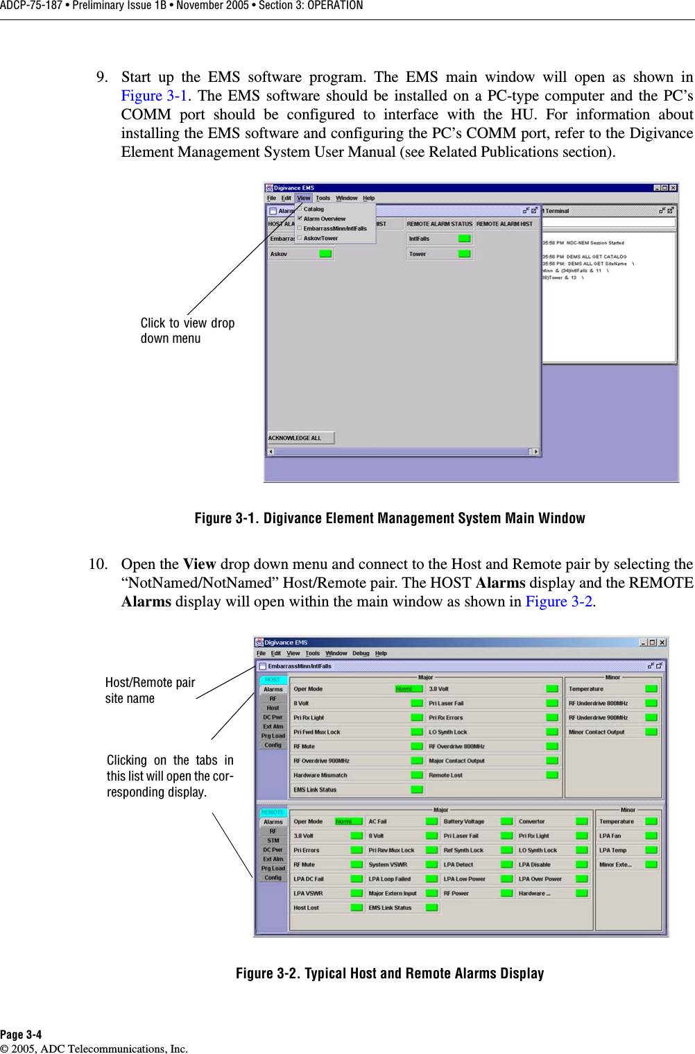
- 3. Users Manual page ix Revised
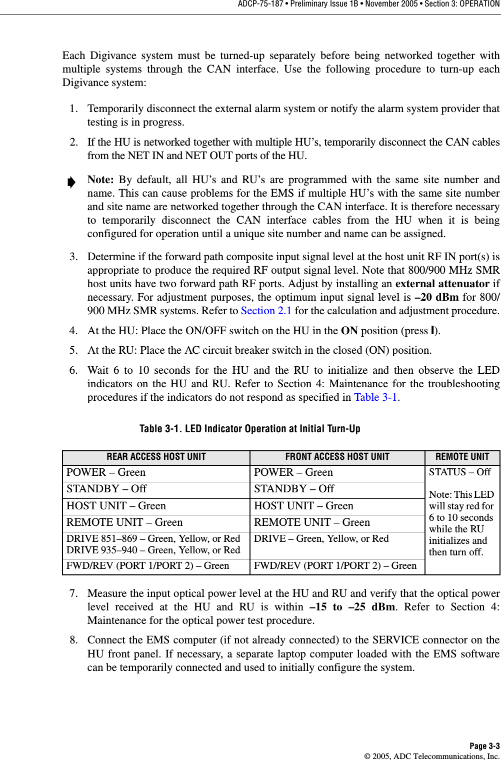
- 4. Users Manual Page 2 26 Revised
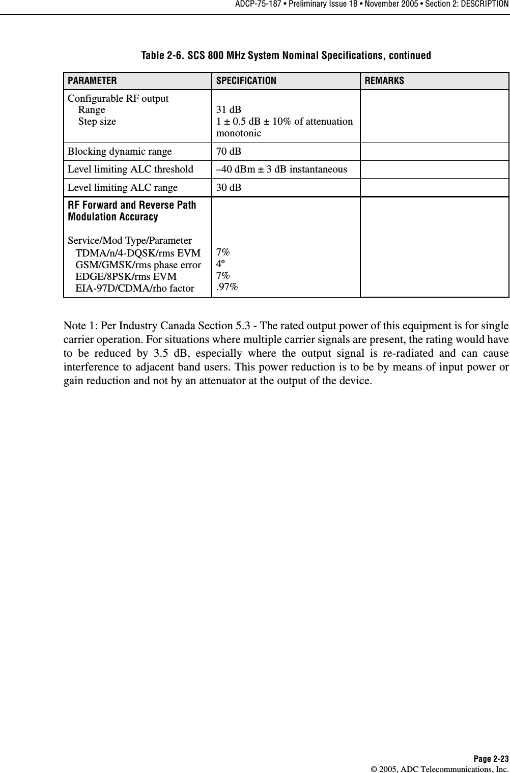
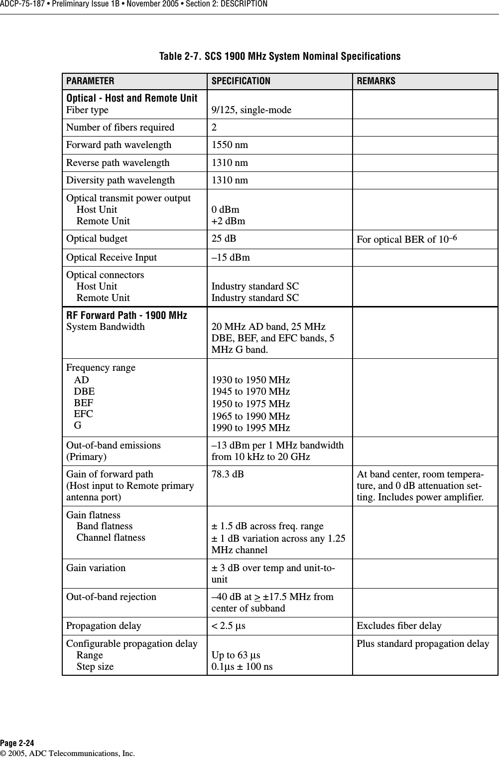
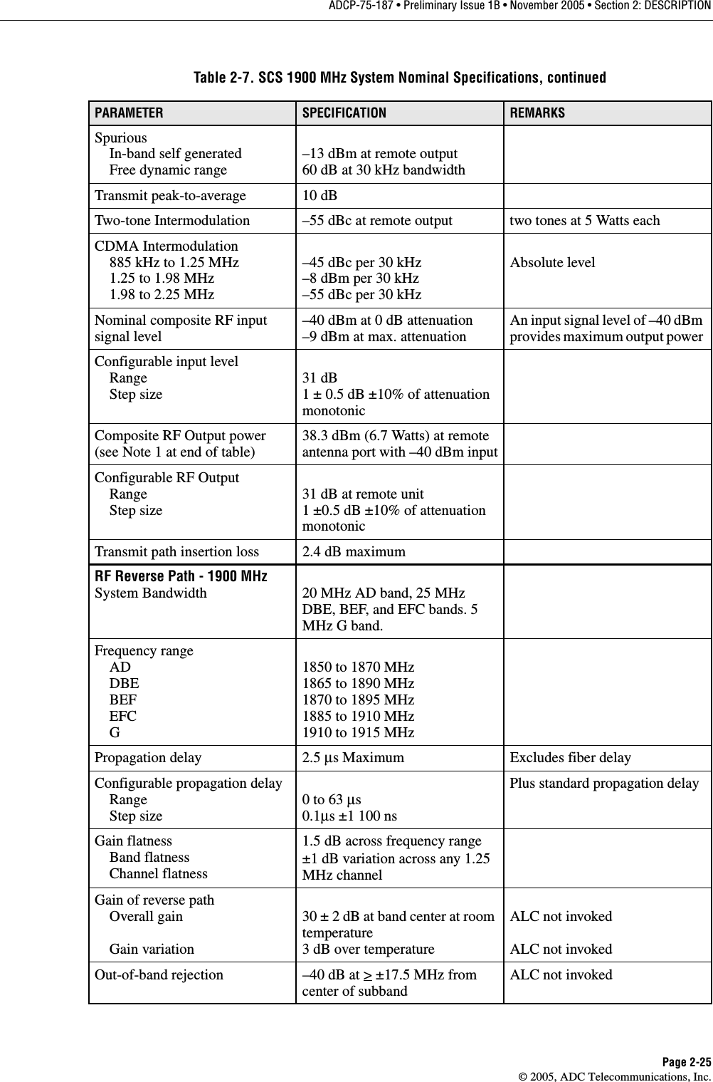
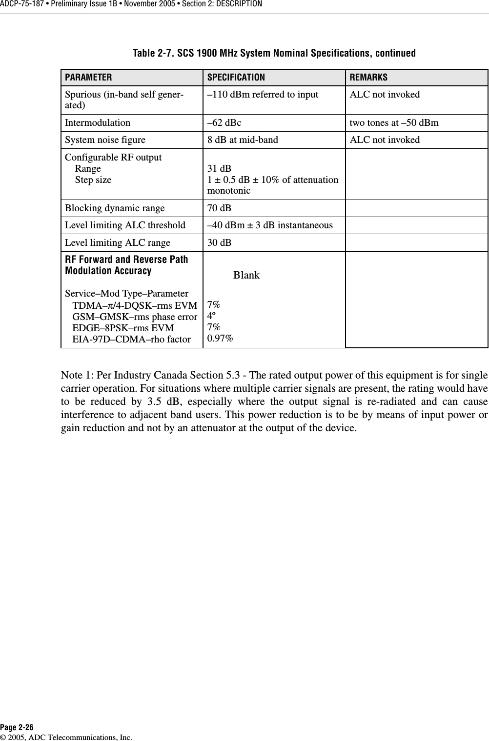
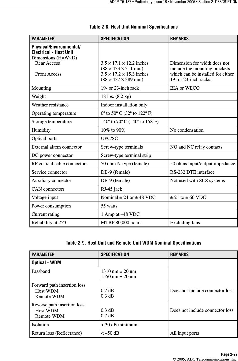
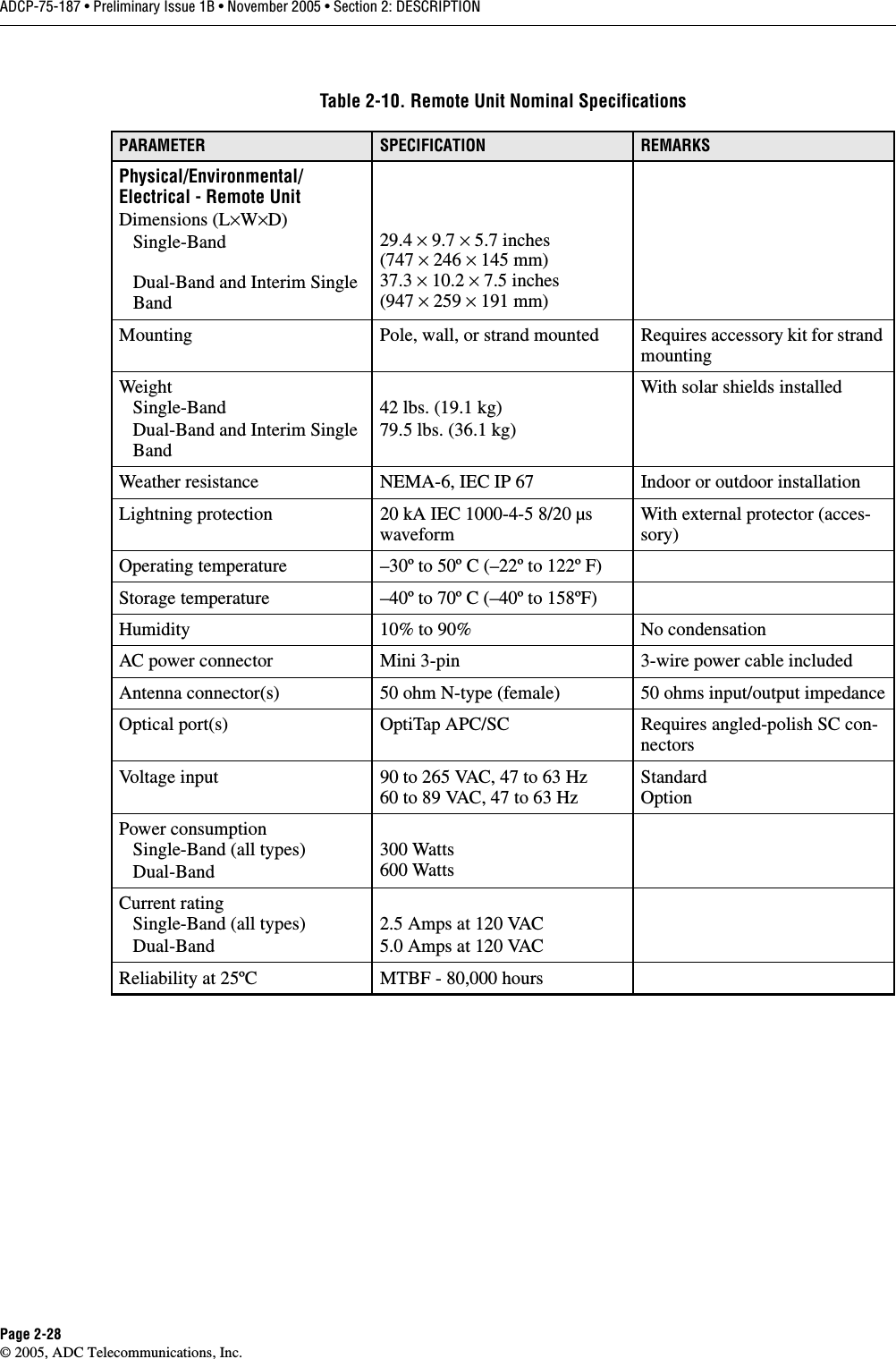
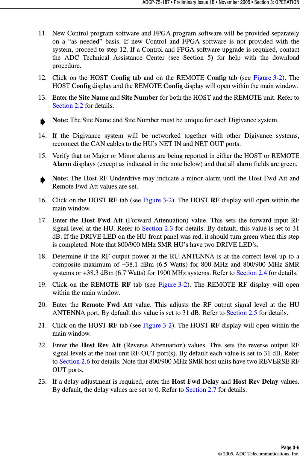
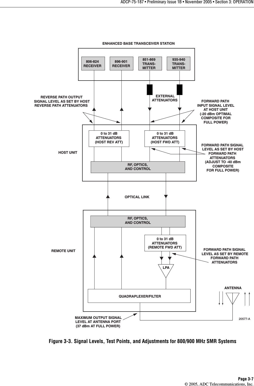
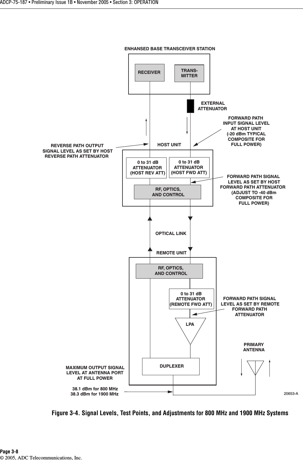
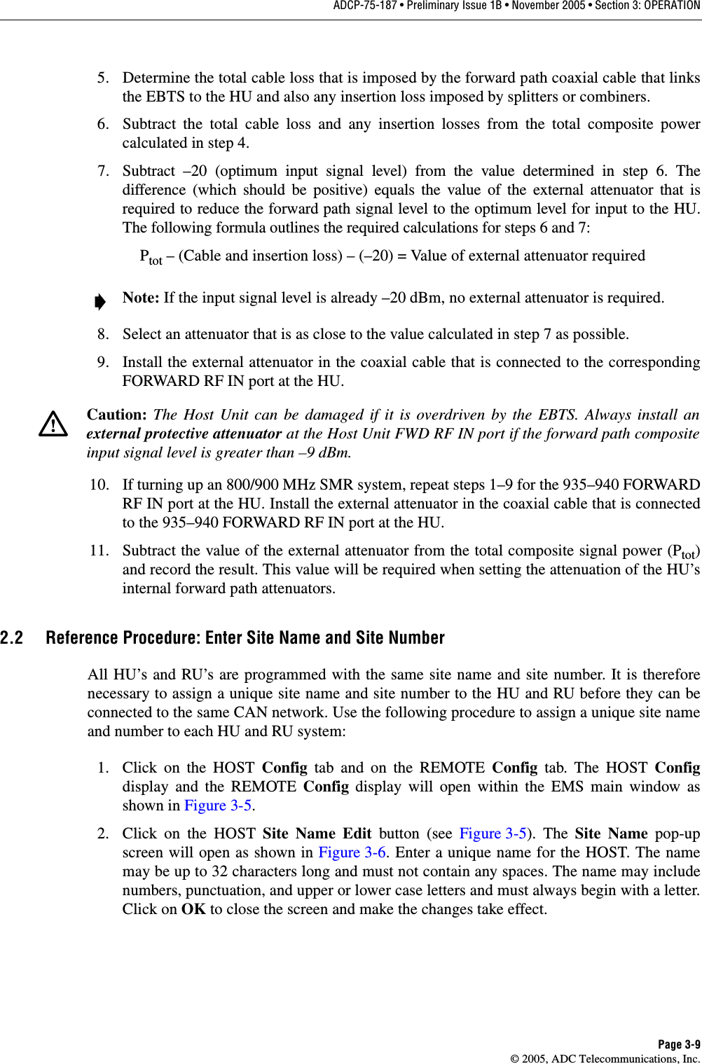
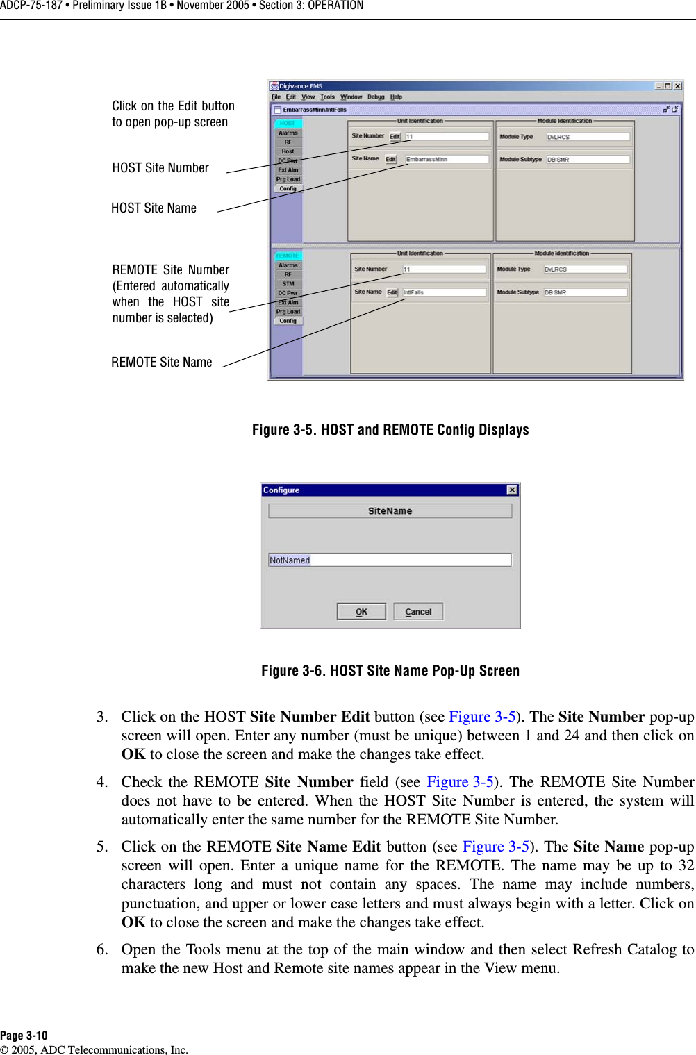
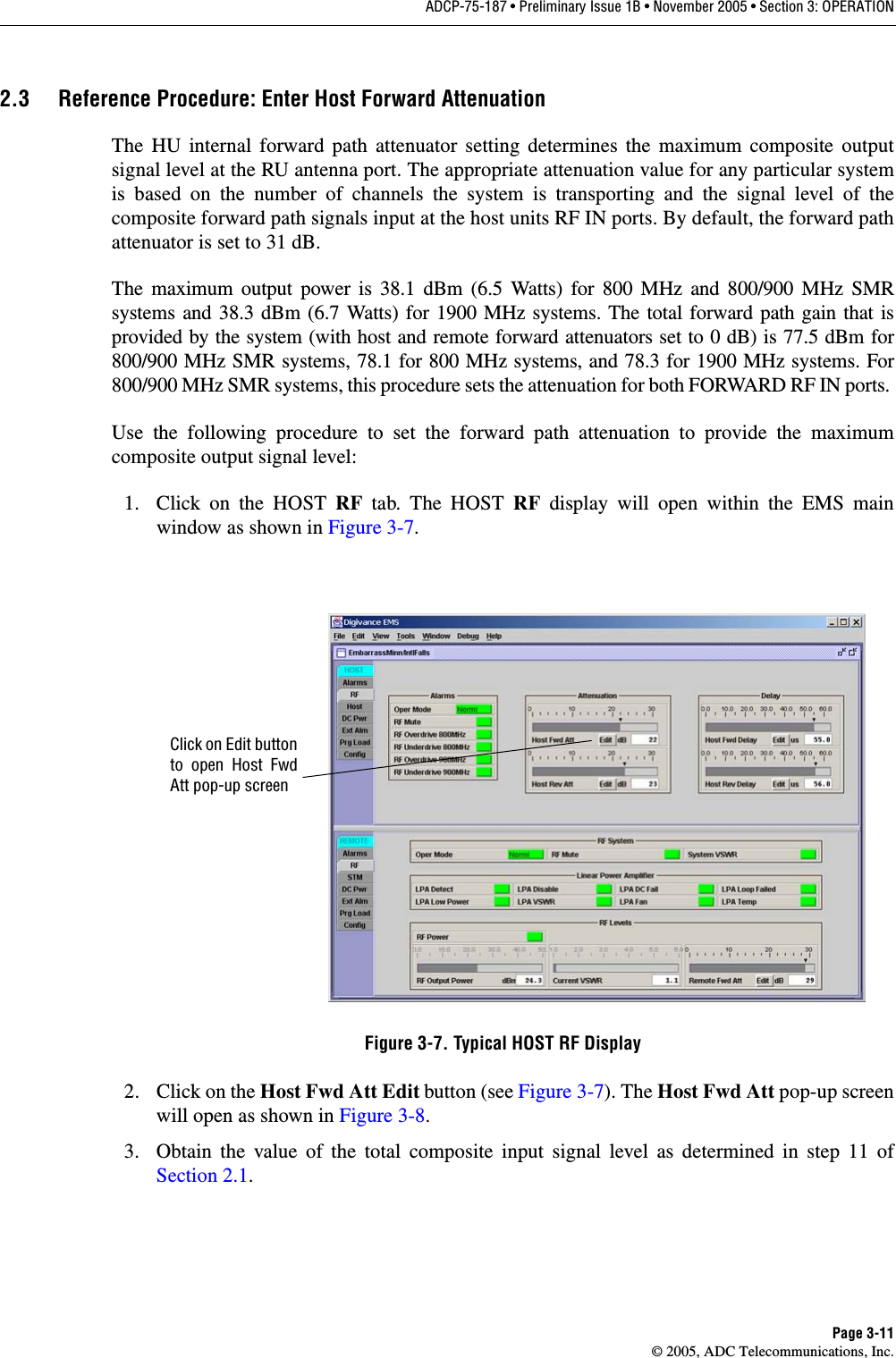
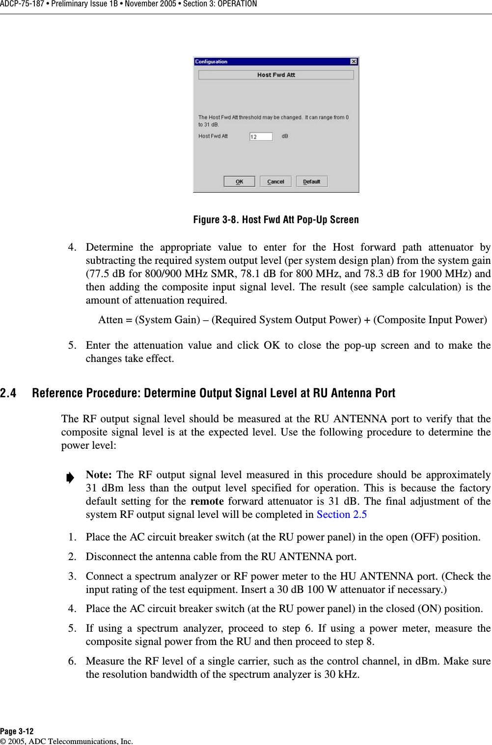
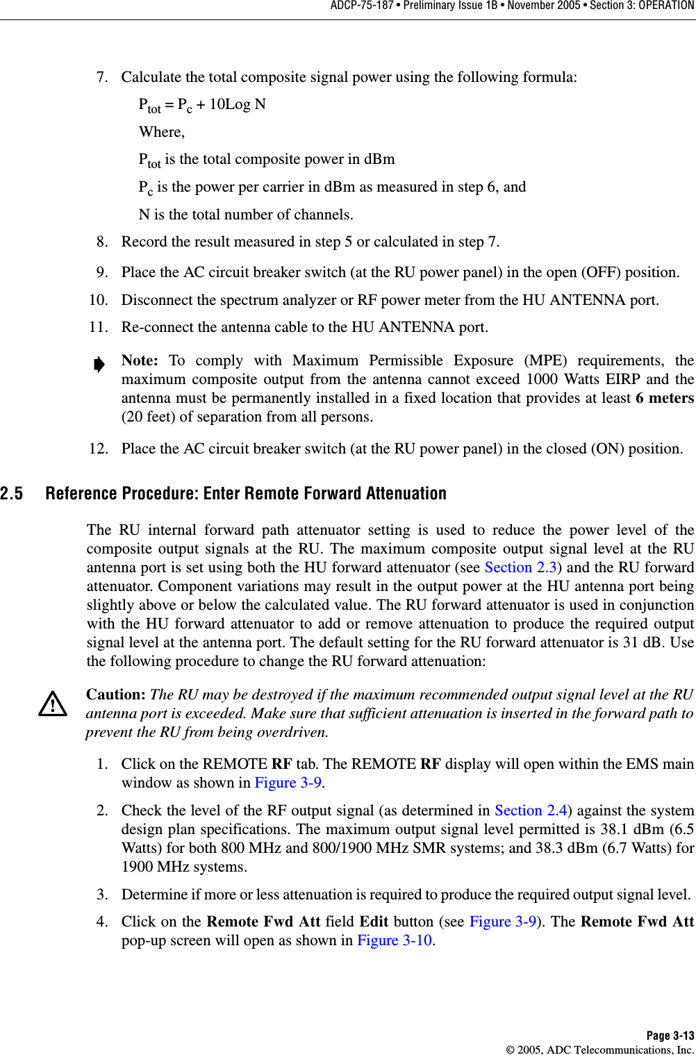
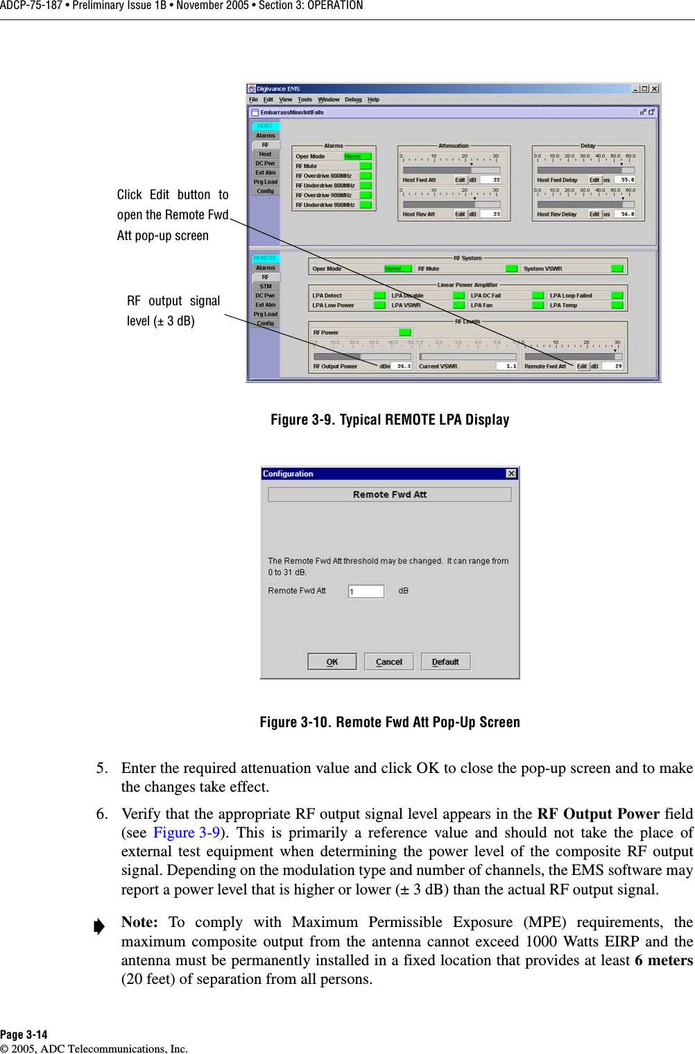
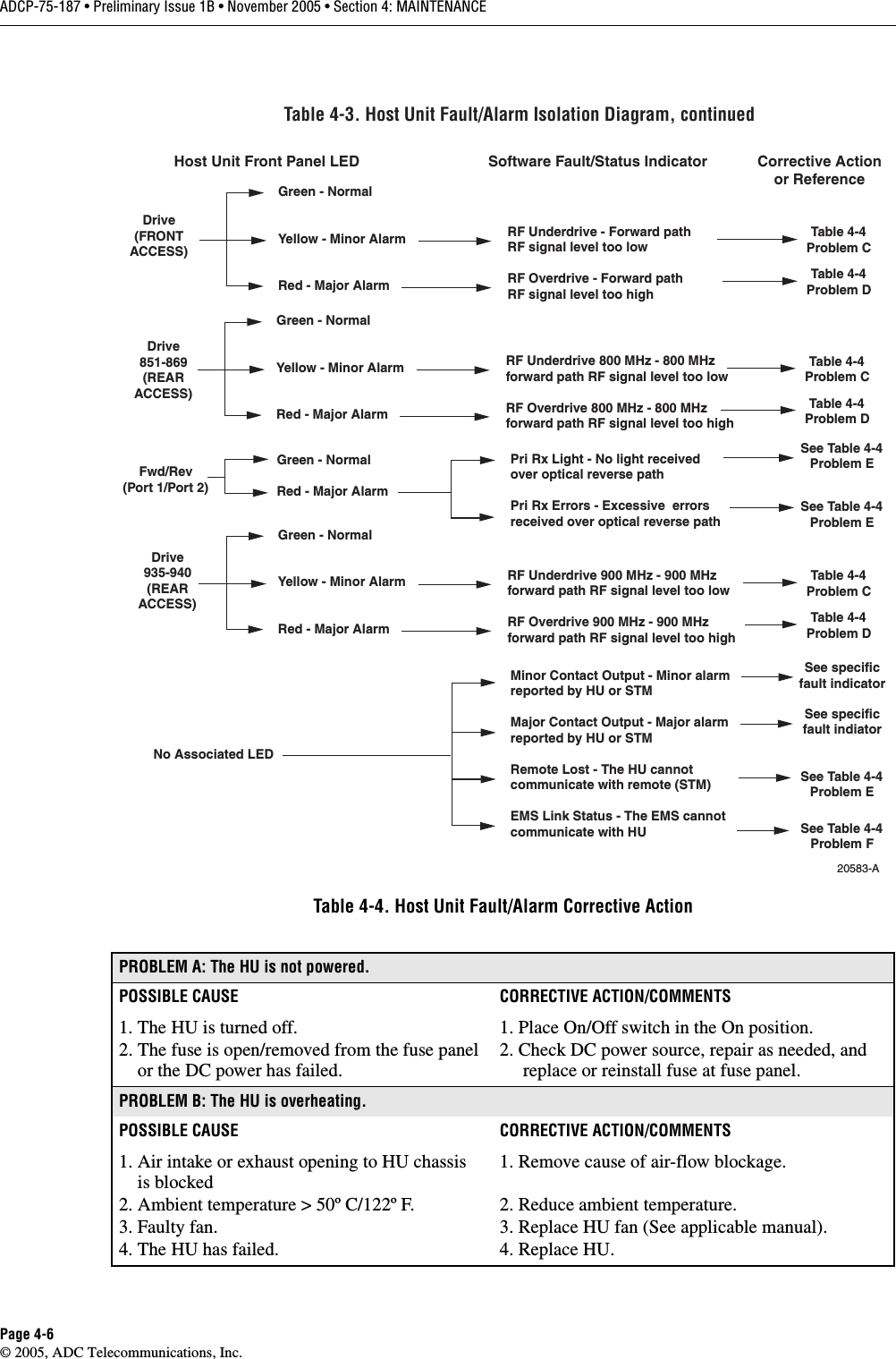
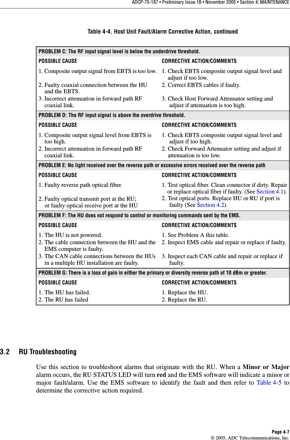
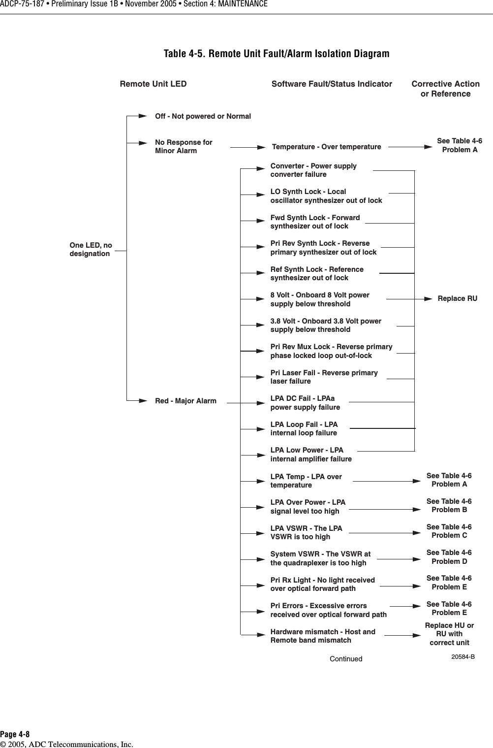
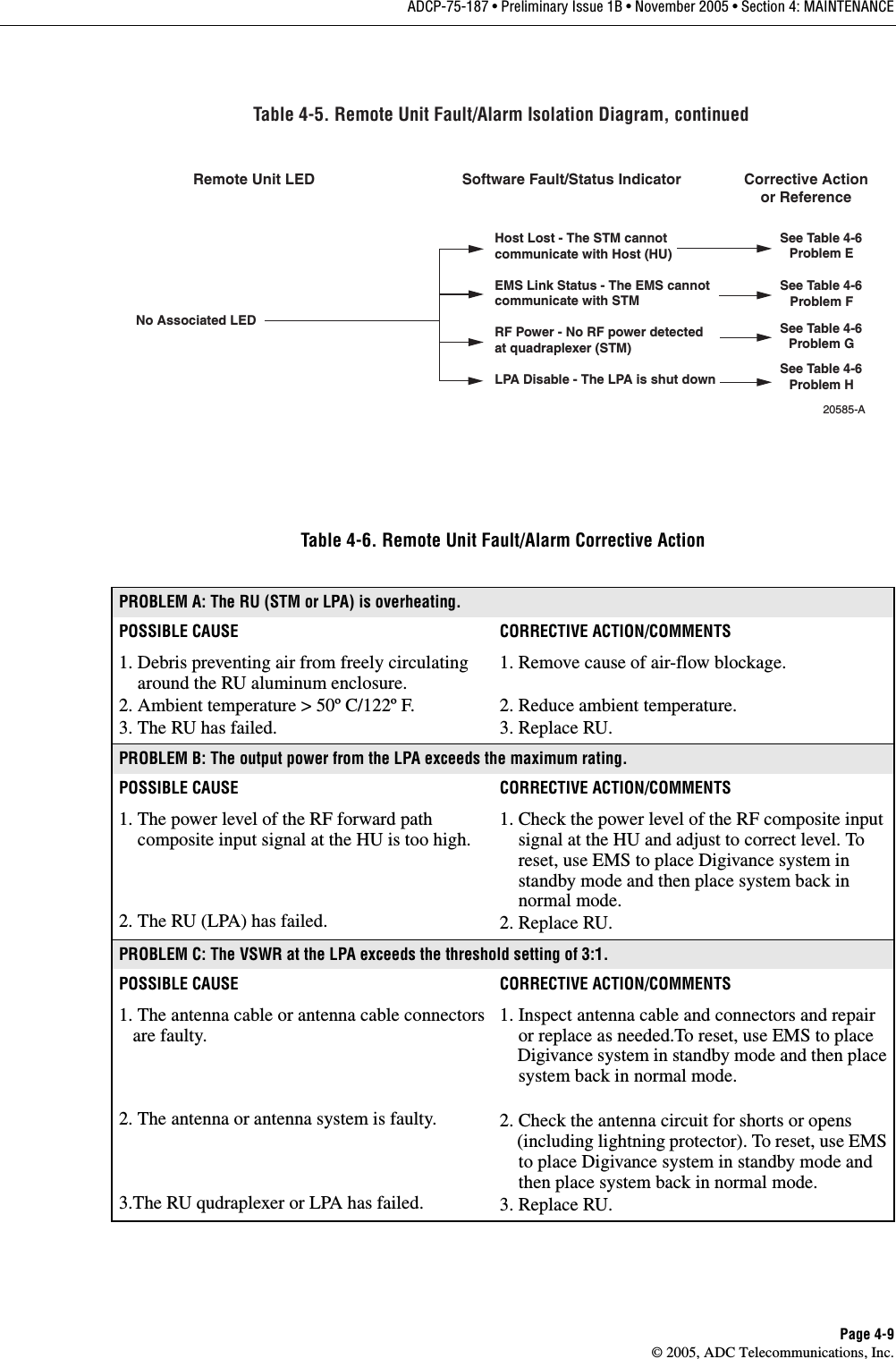
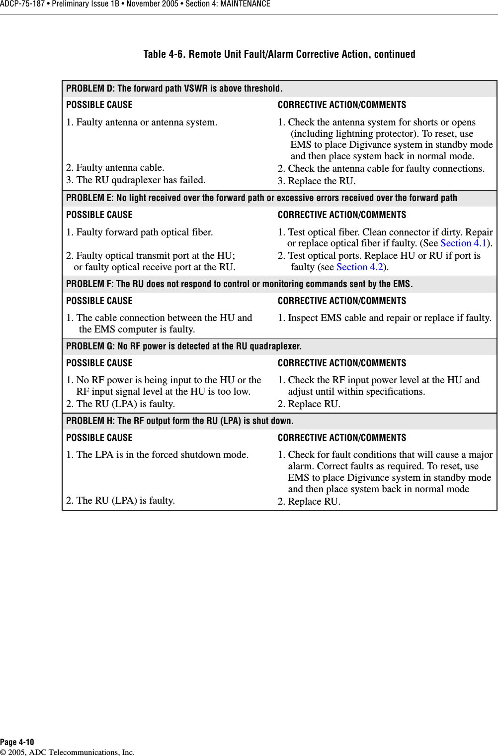
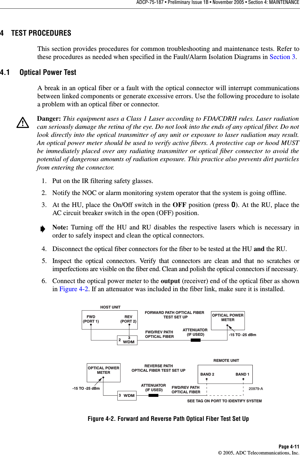
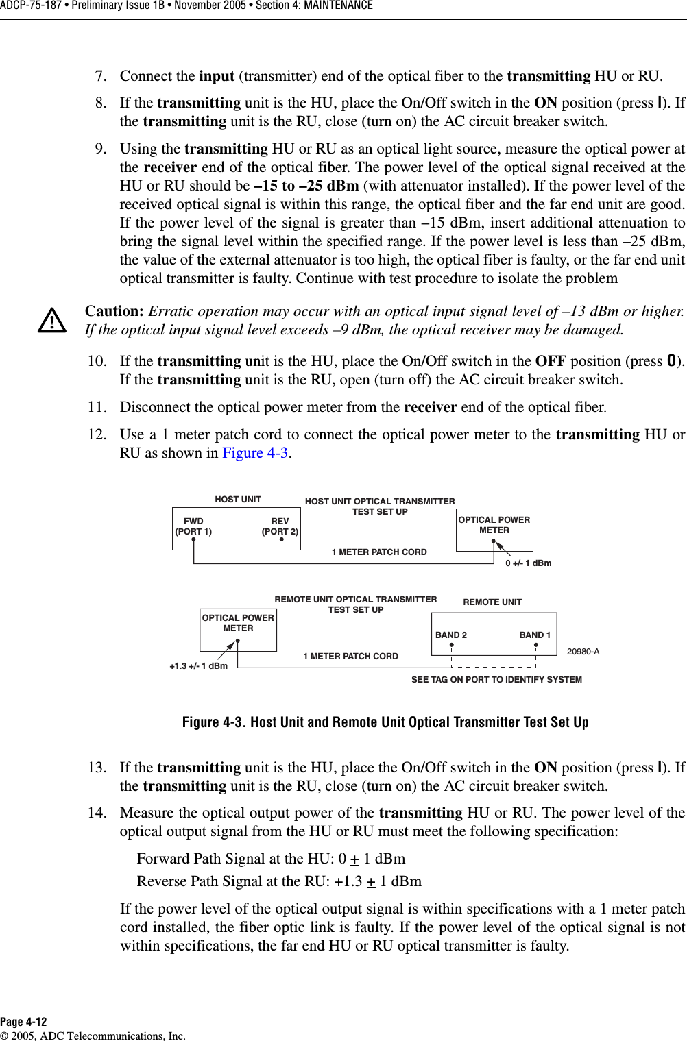
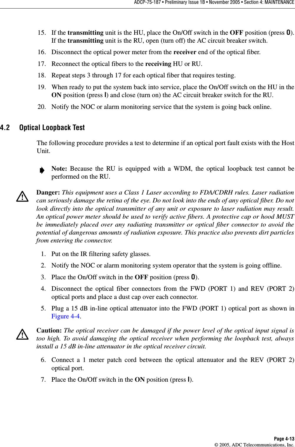
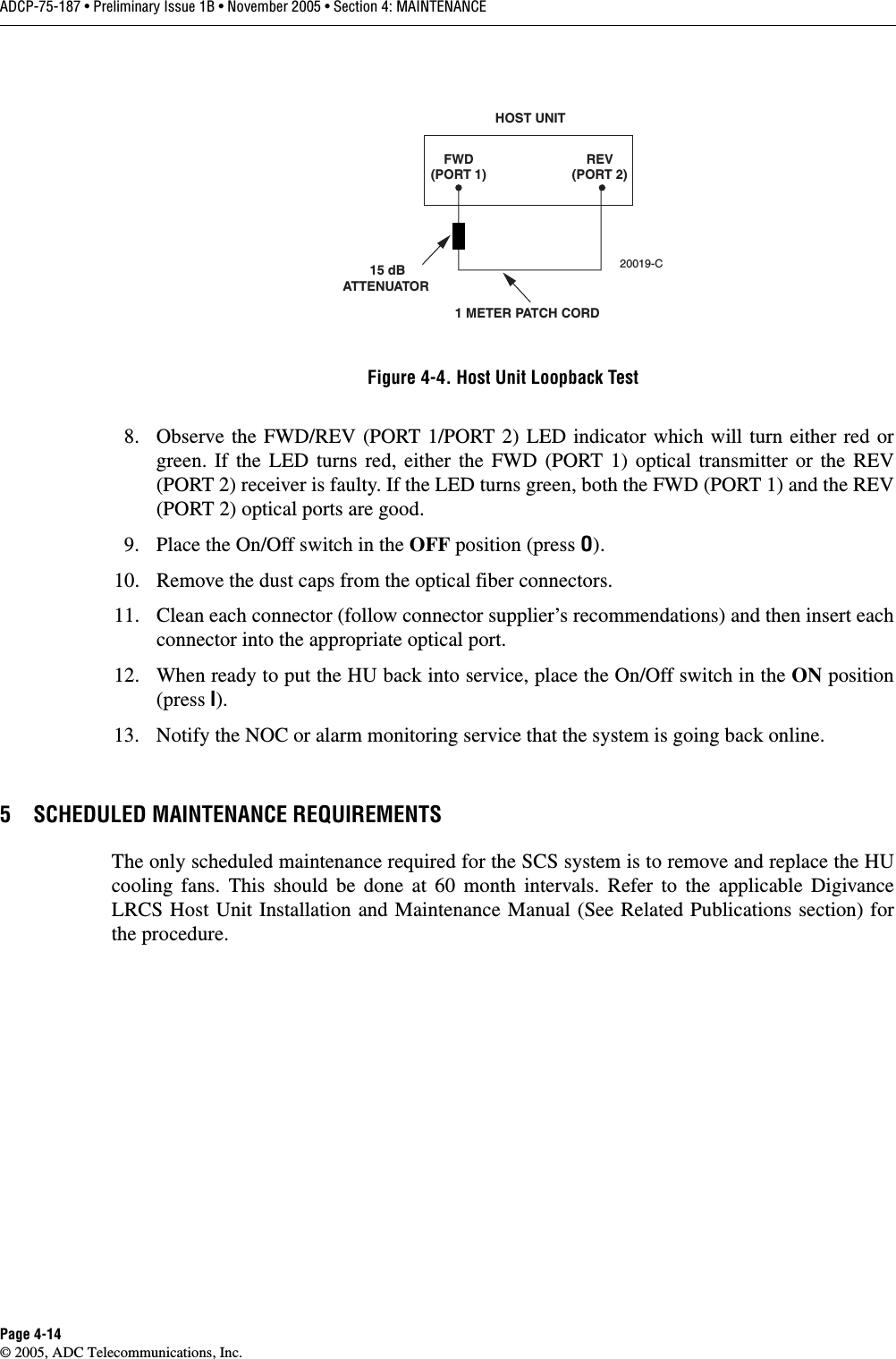
Users Manual Part 2