ADC Telecommunications DSC1901A Digivance SCS 1900 MHz Booster System User Manual 75187
ADC Telecommunications Inc Digivance SCS 1900 MHz Booster System 75187
Contents
- 1. Users Manual Part 1
- 2. Users Manual Part 2
- 3. Users Manual page ix Revised
- 4. Users Manual Page 2 26 Revised
Users Manual Part 2

ADCP-75-187 • Preliminary Issue 1B • November 2005 • Section 2: DESCRIPTION
Page 2-23
© 2005, ADC Telecommunications, Inc.
Note 1: Per Industry Canada Section 5.3 - The rated output power of this equipment is for single
carrier operation. For situations where multiple carrier signals are present, the rating would have
to be reduced by 3.5 dB, especially where the output signal is re-radiated and can cause
interference to adjacent band users. This power reduction is to be by means of input power or
gain reduction and not by an attenuator at the output of the device.
Configurable RF output
Range
Step size
31 dB
1 ± 0.5 dB ± 10% of attenuation
monotonic
Blocking dynamic range 70 dB
Level limiting ALC threshold –40 dBm ± 3 dB instantaneous
Level limiting ALC range 30 dB
RF Forward and Reverse Path
Modulation Accuracy
Service/Mod Type/Parameter
TDMA/n/4-DQSK/rms EVM
GSM/GMSK/rms phase error
EDGE/8PSK/rms EVM
EIA-97D/CDMA/rho factor
7%
4º
7%
.97%
Table 2-6. SCS 800 MHz System Nominal Specifications, continued
PARAMETER SPECIFICATION REMARKS

ADCP-75-187 • Preliminary Issue 1B • November 2005 • Section 2: DESCRIPTION
Page 2-24
© 2005, ADC Telecommunications, Inc.
Table 2-7. SCS 1900 MHz System Nominal Specifications
PARAMETER SPECIFICATION REMARKS
Optical - Host and Remote Unit
Fiber type 9/125, single-mode
Number of fibers required 2
Forward path wavelength 1550 nm
Reverse path wavelength 1310 nm
Diversity path wavelength 1310 nm
Optical transmit power output
Host Unit
Remote Unit
0 dBm
+2 dBm
Optical budget 25 dB For optical BER of 10–6
Optical Receive Input –15 dBm
Optical connectors
Host Unit
Remote Unit
Industry standard SC
Industry standard SC
RF Forward Path - 1900 MHz
System Bandwidth 20 MHz AD band, 25 MHz
DBE, BEF, and EFC bands, 5
MHz G band.
Frequency range
AD
DBE
BEF
EFC
G
1930 to 1950 MHz
1945 to 1970 MHz
1950 to 1975 MHz
1965 to 1990 MHz
1990 to 1995 MHz
Out-of-band emissions
(Primary)
–13 dBm per 1 MHz bandwidth
from 10 kHz to 20 GHz
Gain of forward path
(Host input to Remote primary
antenna port)
78.3 dB At band center, room tempera-
ture, and 0 dB attenuation set-
ting. Includes power amplifier.
Gain flatness
Band flatness
Channel flatness
± 1.5 dB across freq. range
± 1 dB variation across any 1.25
MHz channel
Gain variation ± 3 dB over temp and unit-to-
unit
Out-of-band rejection –40 dB at > ±17.5 MHz from
center of subband
Propagation delay < 2.5 µs Excludes fiber delay
Configurable propagation delay
Range
Step size
Up to 63 µs
0.1µs ± 100 ns
Plus standard propagation delay

ADCP-75-187 • Preliminary Issue 1B • November 2005 • Section 2: DESCRIPTION
Page 2-25
© 2005, ADC Telecommunications, Inc.
Spurious
In-band self generated
Free dynamic range
–13 dBm at remote output
60 dB at 30 kHz bandwidth
Transmit peak-to-average 10 dB
Two-tone Intermodulation –55 dBc at remote output two tones at 5 Watts each
CDMA Intermodulation
885 kHz to 1.25 MHz
1.25 to 1.98 MHz
1.98 to 2.25 MHz
–45 dBc per 30 kHz
–8 dBm per 30 kHz
–55 dBc per 30 kHz
Absolute level
Nominal composite RF input
signal level
–40 dBm at 0 dB attenuation
–9 dBm at max. attenuation
An input signal level of –40 dBm
provides maximum output power
Configurable input level
Range
Step size
31 dB
1 ± 0.5 dB ±10% of attenuation
monotonic
Composite RF Output power
(see Note 1 at end of table)
38.3 dBm (6.7 Watts) at remote
antenna port with –40 dBm input
Configurable RF Output
Range
Step size
31 dB at remote unit
1 ±0.5 dB ±10% of attenuation
monotonic
Transmit path insertion loss 2.4 dB maximum
RF Reverse Path - 1900 MHz
System Bandwidth 20 MHz AD band, 25 MHz
DBE, BEF, and EFC bands. 5
MHz G band.
Frequency range
AD
DBE
BEF
EFC
G
1850 to 1870 MHz
1865 to 1890 MHz
1870 to 1895 MHz
1885 to 1910 MHz
1910 to 1915 MHz
Propagation delay 2.5 µs Maximum Excludes fiber delay
Configurable propagation delay
Range
Step size
0 to 63 µs
0.1µs ±1 100 ns
Plus standard propagation delay
Gain flatness
Band flatness
Channel flatness
1.5 dB across frequency range
±1 dB variation across any 1.25
MHz channel
Gain of reverse path
Overall gain
Gain variation
30 ± 2 dB at band center at room
temperature
3 dB over temperature
ALC not invoked
ALC not invoked
Out-of-band rejection –40 dB at > ±17.5 MHz from
center of subband
ALC not invoked
Table 2-7. SCS 1900 MHz System Nominal Specifications, continued
PARAMETER SPECIFICATION REMARKS

ADCP-75-187 • Preliminary Issue 1B • November 2005 • Section 2: DESCRIPTION
Page 2-26
© 2005, ADC Telecommunications, Inc.
Note 1: Per Industry Canada Section 5.3 - The rated output power of this equipment is for single
carrier operation. For situations where multiple carrier signals are present, the rating would have
to be reduced by 3.5 dB, especially where the output signal is re-radiated and can cause
interference to adjacent band users. This power reduction is to be by means of input power or
gain reduction and not by an attenuator at the output of the device.
Spurious (in-band self gener-
ated)
–110 dBm referred to input ALC not invoked
Intermodulation –62 dBc two tones at –50 dBm
System noise figure 8 dB at mid-band ALC not invoked
Configurable RF output
Range
Step size
31 dB
1 ± 0.5 dB ± 10% of attenuation
monotonic
Blocking dynamic range 70 dB
Level limiting ALC threshold –40 dBm ± 3 dB instantaneous
Level limiting ALC range 30 dB
RF Forward and Reverse Path
Modulation Accuracy
Service–Mod Type–Parameter
TDMA–π/4-DQSK–rms EVM
GSM–GMSK–rms phase error
EDGE–8PSK–rms EVM
EIA-97D–CDMA–rho factor
7%
4º
7%
0.97%
Table 2-7. SCS 1900 MHz System Nominal Specifications, continued
PARAMETER SPECIFICATION REMARKS
Blank

ADCP-75-187 • Preliminary Issue 1B • November 2005 • Section 2: DESCRIPTION
Page 2-27
© 2005, ADC Telecommunications, Inc.
Table 2-8. Host Unit Nominal Specifications
PARAMETER SPECIFICATION REMARKS
Physical/Environmental/
Electrical - Host Unit
Dimensions (H×W×D)
Rear Access
Front Access
3.5 × 17.1 × 12.2 inches
(88 × 433 × 311 mm)
3.5 × 17.2 × 15.3 inches
(88 × 437 × 389 mm)
Dimension for width does not
include the mounting brackets
which can be installed for either
19- or 23-inch racks.
Mounting 19- or 23-inch rack EIA or WECO
Weight 18 lbs. (8.2 kg)
Weather resistance Indoor installation only
Operating temperature 0º to 50º C (32º to 122º F)
Storage temperature –40º to 70º C (–40º to 158ºF)
Humidity 10% to 90% No condensation
Optical ports UPC/SC
External alarm connector Screw-type terminals NO and NC relay contacts
DC power connector Screw-type terminal strip
RF coaxial cable connectors 50 ohm N-type (female) 50 ohms input/output impedance
Service connector DB-9 (female) RS-232 DTE interface
Auxiliary connector DB-9 (female) Not used with SCS systems
CAN connectors RJ-45 jack
Voltage input Nominal ± 24 or ± 48 VDC ± 21 to ± 60 VDC
Power consumption 55 watts
Current rating 1 Amp at –48 VDC
Reliability at 25ºC MTBF 80,000 hours Excluding fans
Table 2-9. Host Unit and Remote Unit WDM Nominal Specifications
PARAMETER SPECIFICATION REMARKS
Optical - WDM
Passband 1310 nm ± 20 nm
1550 nm ± 20 nm
Forward path insertion loss
Host WDM
Remote WDM
0.7 dB
0.3 dB
Does not include connector loss
Reverse path insertion loss
Host WDM
Remote WDM
0.3 dB
0.7 dB
Does not include connector loss
Isolation > 30 dB minimum
Return loss (Reflectance) < –50 dB All input ports

ADCP-75-187 • Preliminary Issue 1B • November 2005 • Section 2: DESCRIPTION
Page 2-28
© 2005, ADC Telecommunications, Inc.
Table 2-10. Remote Unit Nominal Specifications
PARAMETER SPECIFICATION REMARKS
Physical/Environmental/
Electrical - Remote Unit
Dimensions (L×W×D)
Single-Band
Dual-Band and Interim Single
Band
29.4 × 9.7 × 5.7 inches
(747 × 246 × 145 mm)
37.3 × 10.2 × 7.5 inches
(947 × 259 × 191 mm)
Mounting Pole, wall, or strand mounted Requires accessory kit for strand
mounting
Weight
Single-Band
Dual-Band and Interim Single
Band
42 lbs. (19.1 kg)
79.5 lbs. (36.1 kg)
With solar shields installed
Weather resistance NEMA-6, IEC IP 67 Indoor or outdoor installation
Lightning protection 20 kA IEC 1000-4-5 8/20 µs
waveform
With external protector (acces-
sory)
Operating temperature –30º to 50º C (–22º to 122º F)
Storage temperature –40º to 70º C (–40º to 158ºF)
Humidity 10% to 90% No condensation
AC power connector Mini 3-pin 3-wire power cable included
Antenna connector(s) 50 ohm N-type (female) 50 ohms input/output impedance
Optical port(s) OptiTap APC/SC Requires angled-polish SC con-
nectors
Voltage input 90 to 265 VAC, 47 to 63 Hz
60 to 89 VAC, 47 to 63 Hz
Standard
Option
Power consumption
Single-Band (all types)
Dual-Band
300 Watts
600 Watts
Current rating
Single-Band (all types)
Dual-Band
2.5 Amps at 120 VAC
5.0 Amps at 120 VAC
Reliability at 25ºC MTBF - 80,000 hours

ADCP-75-187 • Preliminary Issue 1B • November 2005 • Section 3: OPERATION
Page 3-1
© 2005, ADC Telecommunications, Inc.
SECTION 3: OPERATION
1 BEFORE STARTING OPERATION. . . . . . . . . . . . . . . . . . . . . . . . . . . . . . . . . . . . . . . . . . . . . . . . . . . . . . . . . . . . .3-1
1.1 Tools and Materials . . . . . . . . . . . . . . . . . . . . . . . . . . . . . . . . . . . . . . . . . . . . . . . . . . . . . . . . . . . . . . .3-1
1.2 Readiness Check . . . . . . . . . . . . . . . . . . . . . . . . . . . . . . . . . . . . . . . . . . . . . . . . . . . . . . . . . . . . . . . . .3-2
2 TURN-UP SYSTEM AND VERIFY OPERATION . . . . . . . . . . . . . . . . . . . . . . . . . . . . . . . . . . . . . . . . . . . . . . . . . . . .3-2
2.1 Reference Procedure: Determine Forward Path Input Signal Level . . . . . . . . . . . . . . . . . . . . . . . . . . . . . . .3-6
2.2 Reference Procedure: Enter Site Name and Site Number. . . . . . . . . . . . . . . . . . . . . . . . . . . . . . . . . . . . . .3-9
2.3 Reference Procedure: Enter Host Forward Attenuation . . . . . . . . . . . . . . . . . . . . . . . . . . . . . . . . . . . . . . 3-11
2.4 Reference Procedure: Determine Output Signal Level at RU Antenna Port . . . . . . . . . . . . . . . . . . . . . . . . . 3-12
2.5 Reference Procedure: Enter Remote Forward Attenuation . . . . . . . . . . . . . . . . . . . . . . . . . . . . . . . . . . . .3-13
2.6 Reference Procedure: Enter Host Reverse Attenuation . . . . . . . . . . . . . . . . . . . . . . . . . . . . . . . . . . . . . . 3-15
2.7 Reference Procedure: Enter Host Forward and Reverse Delay . . . . . . . . . . . . . . . . . . . . . . . . . . . . . . . . . 3-16
_________________________________________________________________________________________________________
1 BEFORE STARTING OPERATION
This section provides guidelines for turning-up the Digivance system, verifying that all units are
operating properly, testing to ensure that all performance requirements are satisfied, and
correcting any installation problems. This process assumes that the various units have been
installed in accordance with the system design plan.
1.1 Tools and Materials
The following tools and materials are required in order to complete the procedures in this
section:
• Portable spectrum analyzer or RF power meter
• DC voltmeter
• External RF and optical attenuators (if specified in system design plan)
• PC-type computer with Digivance Element Management System (EMS) Version 3.01
software installed
• Straight-through RS-232 DB-9 interface cable (accessory)
•Handset
•Pencil or pen
• Writing pad
Content Page

ADCP-75-187 • Preliminary Issue 1B • November 2005 • Section 3: OPERATION
Page 3-2
© 2005, ADC Telecommunications, Inc.
1.2 Readiness Check
Before starting the turn-up process, inspect the complete Digivance system to verify that all
components of the system are ready to be powered-up. This will ensure that no units of the
system will be damaged during turn-up and that all existing systems will continue to function
properly.
1.2.1 Host Unit Installation Checks
Complete the following checks at the HU prior to starting the turn-up process:
1. Verify that the ON/OFF switch on the HU is in the OFF position (press O).
2. At the fuse panel, install a 3 Amp GMT fuse in the circuit that supplies DC power to the HU.
3. Using a DC voltmeter, verify that the DC voltage level at the HU power terminals is
between ± 21 to ± 60 VDC (nominal ± 24 or ± 48 VDC). The DC power provided to the
HU can be either polarity.
4. Verify that all electrical and optical connections have been completed and that all optical
fibers, coaxial cables, and wires are properly routed and secured.
1.2.2 Remote Unit Installation Checks
Complete the following checks at the RU prior to starting the turn-up process:
1. Verify that all electrical and optical connections have been completed and that all optical
fibers, coaxial cables, and wires are properly routed and secured.
2. At the AC breaker box, make sure the circuit breaker for the circuit that supplies AC power
to the RU is in the open (off) position.
2 TURN-UP SYSTEM AND VERIFY OPERATION
The process of turning-up the system and verifying operation involves powering up the various
system components, verifying that the LED indicators show normal operation, setting the site
number and name, adjusting the RF signal levels, and adjusting the path delay.
Note: When connecting the equipment to the supply circuit, be sure to check equipment
nameplate ratings to avoid overloading circuits which may cause damage to over-current
protection devices and supply wiring.
Note: SCS systems that include a dual-band RU are comprised of two systems that operate
and function independently of each other. Each system can be independently turned-up,
tested, and placed into service. The EMS will recognize each system regardless of the
frequency/band and will display the appropriate screens. The frequency/band can be
verified by clicking on the HOST Host tab and on the REMOTE STM tab. The frequency/
band for the selected system will be displayed on the right side of the screen.

ADCP-75-187 • Preliminary Issue 1B • November 2005 • Section 3: OPERATION
Page 3-3
© 2005, ADC Telecommunications, Inc.
Each Digivance system must be turned-up separately before being networked together with
multiple systems through the CAN interface. Use the following procedure to turn-up each
Digivance system:
1. Temporarily disconnect the external alarm system or notify the alarm system provider that
testing is in progress.
2. If the HU is networked together with multiple HU’s, temporarily disconnect the CAN cables
from the NET IN and NET OUT ports of the HU.
3. Determine if the forward path composite input signal level at the host unit RF IN port(s) is
appropriate to produce the required RF output signal level. Note that 800/900 MHz SMR
host units have two forward path RF ports. Adjust by installing an external attenuator if
necessary. For adjustment purposes, the optimum input signal level is –20 dBm for 800/
900 MHz SMR systems. Refer to Section 2.1 for the calculation and adjustment procedure.
4. At the HU: Place the ON/OFF switch on the HU in the ON position (press I).
5. At the RU: Place the AC circuit breaker switch in the closed (ON) position.
6. Wait 6 to 10 seconds for the HU and the RU to initialize and then observe the LED
indicators on the HU and RU. Refer to Section 4: Maintenance for the troubleshooting
procedures if the indicators do not respond as specified in Table 3-1.
Table 3-1. LED Indicator Operation at Initial Turn-Up
7. Measure the input optical power level at the HU and RU and verify that the optical power
level received at the HU and RU is within –15 to –25 dBm. Refer to Section 4:
Maintenance for the optical power test procedure.
8. Connect the EMS computer (if not already connected) to the SERVICE connector on the
HU front panel. If necessary, a separate laptop computer loaded with the EMS software
can be temporarily connected and used to initially configure the system.
Note: By default, all HU’s and RU’s are programmed with the same site number and
name. This can cause problems for the EMS if multiple HU’s with the same site number
and site name are networked together through the CAN interface. It is therefore necessary
to temporarily disconnect the CAN interface cables from the HU when it is being
configured for operation until a unique site number and name can be assigned.
REAR ACCESS HOST UNIT FRONT ACCESS HOST UNIT REMOTE UNIT
POWER – Green POWER – Green STATUS – Off
Note: This LED
will stay red for
6 to 10 seconds
while the RU
initializes and
then turn off.
STANDBY – Off STANDBY – Off
HOST UNIT – Green HOST UNIT – Green
REMOTE UNIT – Green REMOTE UNIT – Green
DRIVE 851–869 – Green, Yellow, or Red
DRIVE 935–940 – Green, Yellow, or Red
DRIVE – Green, Yellow, or Red
FWD/REV (PORT 1/PORT 2) – Green FWD/REV (PORT 1/PORT 2) – Green
ADCP-75-187 • Preliminary Issue 1B • November 2005 • Section 3: OPERATION
Page 3-4
© 2005, ADC Telecommunications, Inc.
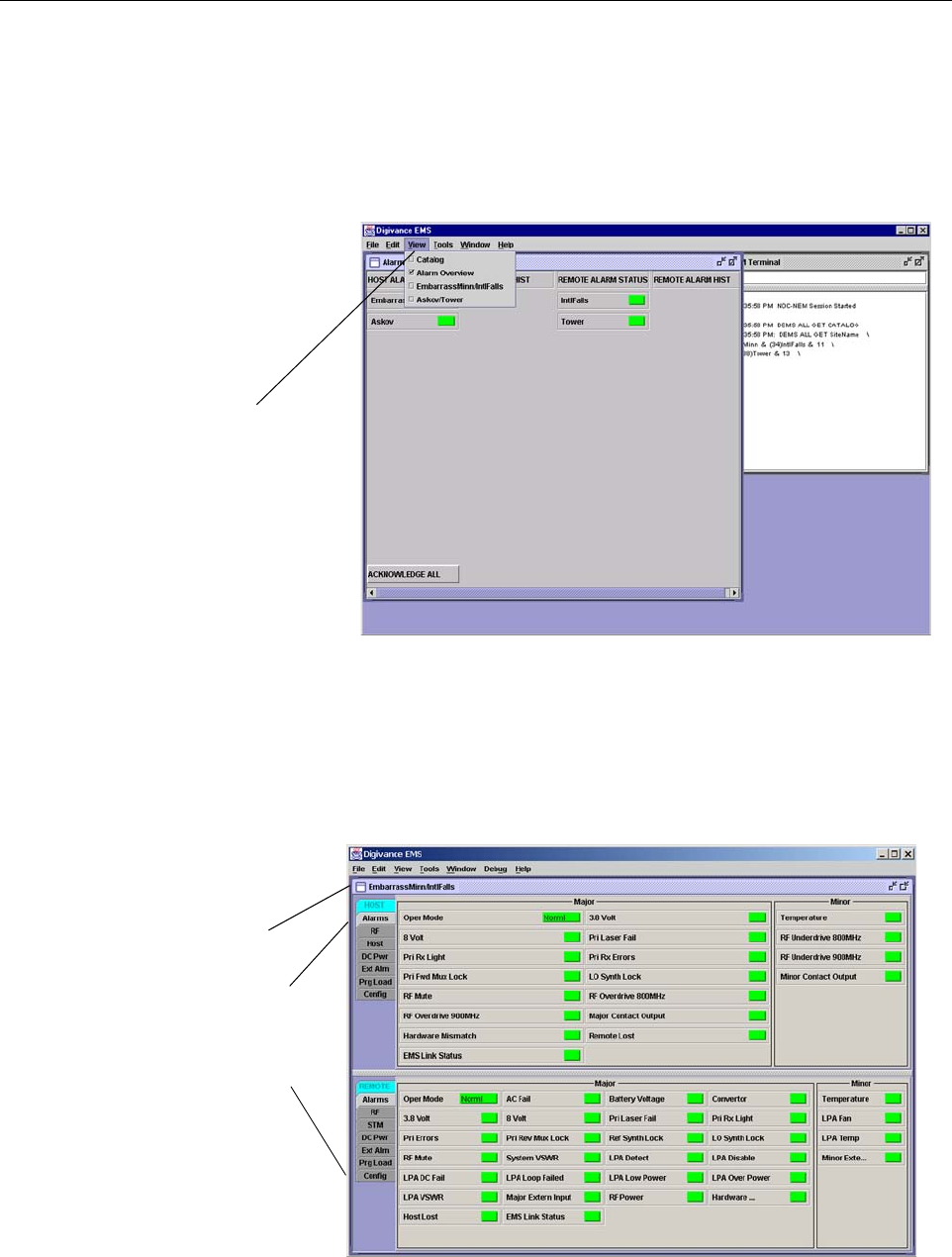
9. Start up the EMS software program. The EMS main window will open as shown in
Figure 3-1. The EMS software should be installed on a PC-type computer and the PC’s
COMM port should be configured to interface with the HU. For information about
installing the EMS software and configuring the PC’s COMM port, refer to the Digivance
Element Management System User Manual (see Related Publications section).
Figure 3-1. Digivance Element Management System Main Window
10. Open the View drop down menu and connect to the Host and Remote pair by selecting the
“NotNamed/NotNamed” Host/Remote pair. The HOST Alarms display and the REMOTE
Alarms display will open within the main window as shown in Figure 3-2.
Figure 3-2. Typical Host and Remote Alarms Display
Click to view drop
down menu
Clicking on the tabs in
this list will open the cor-
responding display.
Host/Remote pair
site name

ADCP-75-187 • Preliminary Issue 1B • November 2005 • Section 3: OPERATION
Page 3-5
© 2005, ADC Telecommunications, Inc.
11. New Control program software and FPGA program software will be provided separately
on a “as needed” basis. If new Control and FPGA software is not provided with the
system, proceed to step 12. If a Control and FPGA software upgrade is required, contact
the ADC Technical Assistance Center (see Section 5) for help with the download
procedure.
12. Click on the HOST Config tab and on the REMOTE Config tab (see Figure 3-2). The
HOST Config display and the REMOTE Config display will open within the main window.
13. Enter the Site Name and Site Number for both the HOST and the REMOTE unit. Refer to
Section 2.2 for details.
14. If the Digivance system will be networked together with other Digivance systems,
reconnect the CAN cables to the HU’s NET IN and NET OUT ports.
15. Verify that no Major or Minor alarms are being reported in either the HOST or REMOTE
Alarm displays (except as indicated in the note below) and that all alarm fields are green.
16. Click on the HOST RF tab (see Figure 3-2). The HOST RF display will open within the
main window.
17. Enter the Host Fwd Att (Forward Attenuation) value. This sets the forward input RF
signal level at the HU. Refer to Section 2.3 for details. By default, this value is set to 31
dB. If the DRIVE LED on the HU front panel was red, it should turn green when this step
is completed. Note that 800/900 MHz SMR HU’s have two DRIVE LED’s.
18. Determine if the RF output power at the RU ANTENNA is at the correct level up to a
composite maximum of +38.1 dBm (6.5 Watts) for 800 MHz and 800/900 MHz SMR
systems or +38.3 dBm (6.7 Watts) for 1900 MHz systems. Refer to Section 2.4 for details.
19. Click on the REMOTE RF tab (see Figure 3-2). The REMOTE RF display will open
within the main window.
20. Enter the Remote Fwd Att value. This adjusts the RF output signal level at the HU
ANTENNA port. By default this value is set to 31 dB. Refer to Section 2.5 for details.
21. Click on the HOST RF tab (see Figure 3-2). The HOST RF display will open within the
main window.
22. Enter the Host Rev Att (Reverse Attenuation) values. This sets the reverse output RF
signal levels at the host unit RF OUT port(s). By default each value is set to 31 dB. Refer
to Section 2.6 for details. Note that 800/900 MHz SMR host units have two REVERSE RF
OUT ports.
23. If a delay adjustment is required, enter the Host Fwd Delay and Host Rev Delay values.
By default, the delay values are set to 0. Refer to Section 2.7 for details.
Note: The Site Name and Site Number must be unique for each Digivance system.
Note: The Host RF Underdrive may indicate a minor alarm until the Host Fwd Att and
Remote Fwd Att values are set.

ADCP-75-187 • Preliminary Issue 1B • November 2005 • Section 3: OPERATION
Page 3-6
© 2005, ADC Telecommunications, Inc.
24. If a separate laptop computer loaded with the EMS software was used to initially
configure the system, disconnect the laptop computer from the SERVICE connector.
25. Reconnect the external alarm system or notify the alarm system provider that the turn-up
process has been completed.
2.1 Reference Procedure: Determine Forward Path Input Signal Level
The level of the composite RF input signals received at the host unit FORWARD RF IN port(s)
will vary depending on the EBTS, the cable loss, the number of channels present, and the
required forward path composite power. If maximum composite RF output is required at the
RU, the level of the composite RF input signal received at the HU must fall within a range of –9
to –40 dBm. If the signal level is not within this range, it must be adjusted using an external
attenuator. Note: The 800/900 MHz SMR host unit has two FORWARD RF IN ports. Use the
851–869 FORWARD RF IN port to complete this procedure. Then repeat this procedure for the
935–940 FORWARD RF IN port.
When connecting a single HU to a single EBTS, use the following procedure to measure and
adjust the input RF signal level at the HU:
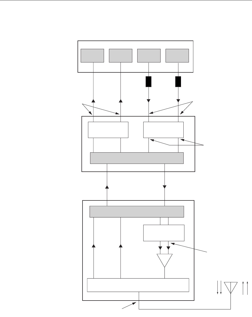
1. Connect a spectrum analyzer or power meter to the forward path output port at the EBTS.
The required signal levels and test points for 800/900 MHz SMR systems are shown in
Figure 3-3. The required signal levels and test points for 800 MHz and 1900 MHz
systems are shown in Figure 3-4. Note that 800/900 MHz SMR Host Units have two
forward path ports.
2. If using a spectrum analyzer, proceed to step 3. If using a power meter, measure the
composite signal power from the EBTS and then proceed to step 5.
3. Measure the RF level of a single carrier, such as the control channel, in dBm. Make sure
the resolution bandwidth of the spectrum analyzer is 30 kHz. Maximum power in any
channel should not exceed 5W (+37 dB).
4. Calculate the total composite signal power from the EBTS using the following formula:
Ptot = Pc + 10Log N where,
Ptot is the total composite power in dBm
Pc is the power per carrier in dBm as measured in step 3, and
N is the total number of channels.
Note: When two or more HU’s are connected together through the CAN interface, only
one EMS computer is required to manage the networked Digivance systems. The EMS
computer may be connected to the SERVICE port on any one of the HUs in the network.
Note: The optimum level for an 800/900 MHz SMR composite input signal is –20 dBm
Note: Check the input rating of the test equipment and the output rating of the EBTS. To
avoid burning out the spectrum analyzer or power meter, it may be necessary to insert a
30 dB 100W (or similar) attenuator between the EBTS and test equipment.
ADCP-75-187 • Preliminary Issue 1B • November 2005 • Section 3: OPERATION
Page 3-7
© 2005, ADC Telecommunications, Inc.
Figure 3-3. Signal Levels, Test Points, and Adjustments for 800/900 MHz SMR Systems
FORWARD PATH
INPUT SIGNAL LEVEL
AT HOST UNIT
(-20 dBm OPTIMAL
COMPOSITE FOR
FULL POWER)
HOST UNIT
REMOTE UNIT
ENHANCED BASE TRANSCEIVER STATION
20577-A
OPTICAL LINK
ANTENNA
QUADRAPLEXER/FILTER
FORWARD PATH SIGNAL
LEVEL AS SET BY HOST
FORWARD PATH
ATTENUATORS
(ADJUST TO -40 dBm
COMPOSITE
FOR FULL POWER)
REVERSE PATH OUTPUT
SIGNAL LEVEL AS SET BY HOST
REVERSE PATH ATTENUATORS
MAXIMUM OUTPUT SIGNAL
LEVEL AT ANTENNA PORT
(37 dBm AT FULL POWER)
FORWARD PATH SIGNAL
LEVEL AS SET BY REMOTE
FORWARD PATH
ATTENUATORS
LPA
EXTERNAL
ATTENUATORS
851-869
TRANS-
MITTER
935-940
TRANS-
MITTER
0 to 31 dB
ATTENUATORS
(HOST FWD ATT)
0 to 31 dB
ATTENUATORS
(HOST REV ATT)
0 to 31 dB
ATTENUATORS
(REMOTE FWD ATT)
RF, OPTICS,
AND CONTROL
RF, OPTICS,
AND CONTROL
896-901
RECEIVER
806-824
RECEIVER
ADCP-75-187 • Preliminary Issue 1B • November 2005 • Section 3: OPERATION
Page 3-8
© 2005, ADC Telecommunications, Inc.
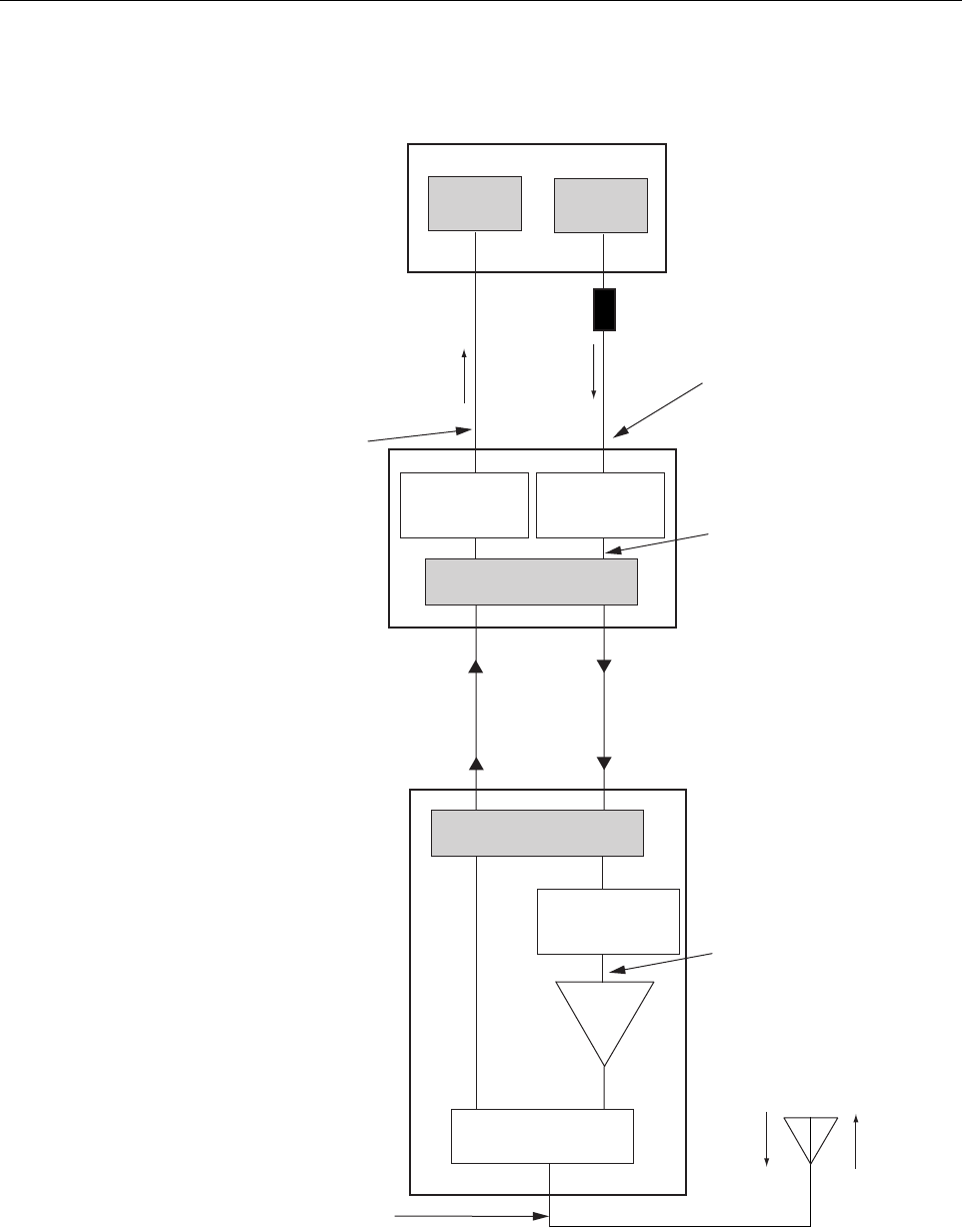
Figure 3-4. Signal Levels, Test Points, and Adjustments for 800 MHz and 1900 MHz Systems
FORWARD PATH
INPUT SIGNAL LEVEL
AT HOST UNIT
(-20 dBm TYPICAL
COMPOSITE FOR
FULL POWER)
HOST UNIT
PRIMARY
ANTENNA
LPA
REMOTE UNIT
ENHANSED BASE TRANSCEIVER STATION
20653-A
EXTERNAL
ATTENUATOR
TRANS-
MITTER
RECEIVER
0 to 31 dB
ATTENUATOR
(HOST REV ATT)
0 to 31 dB
ATTENUATOR
(HOST FWD ATT)
RF, OPTICS,
AND CONTROL
0 to 31 dB
ATTENUATOR
(REMOTE FWD ATT)
OPTICAL LINK
RF, OPTICS,
AND CONTROL
DUPLEXER
FORWARD PATH SIGNAL
LEVEL AS SET BY HOST
FORWARD PATH ATTENUATOR
(ADJUST TO -40 dBm
COMPOSITE FOR
FULL POWER)
REVERSE PATH OUTPUT
SIGNAL LEVEL AS SET BY HOST
REVERSE PATH ATTENUATOR
MAXIMUM OUTPUT SIGNAL
LEVEL AT ANTENNA PORT
AT FULL POWER
38.1 dBm for 800 MHz
38.3 dBm for 1900 MHz
FORWARD PATH SIGNAL
LEVEL AS SET BY REMOTE
FORWARD PATH
ATTENUATOR

ADCP-75-187 • Preliminary Issue 1B • November 2005 • Section 3: OPERATION
Page 3-9
© 2005, ADC Telecommunications, Inc.
5. Determine the total cable loss that is imposed by the forward path coaxial cable that links
the EBTS to the HU and also any insertion loss imposed by splitters or combiners.
6. Subtract the total cable loss and any insertion losses from the total composite power
calculated in step 4.
7. Subtract –20 (optimum input signal level) from the value determined in step 6. The
difference (which should be positive) equals the value of the external attenuator that is
required to reduce the forward path signal level to the optimum level for input to the HU.
The following formula outlines the required calculations for steps 6 and 7:
Ptot – (Cable and insertion loss) – (–20) = Value of external attenuator required
8. Select an attenuator that is as close to the value calculated in step 7 as possible.
9. Install the external attenuator in the coaxial cable that is connected to the corresponding
FORWARD RF IN port at the HU.
10. If turning up an 800/900 MHz SMR system, repeat steps 1–9 for the 935–940 FORWARD
RF IN port at the HU. Install the external attenuator in the coaxial cable that is connected
to the 935–940 FORWARD RF IN port at the HU.
11. Subtract the value of the external attenuator from the total composite signal power (Ptot)
and record the result. This value will be required when setting the attenuation of the HU’s
internal forward path attenuators.
2.2 Reference Procedure: Enter Site Name and Site Number
All HU’s and RU’s are programmed with the same site name and site number. It is therefore
necessary to assign a unique site name and site number to the HU and RU before they can be
connected to the same CAN network. Use the following procedure to assign a unique site name
and number to each HU and RU system:
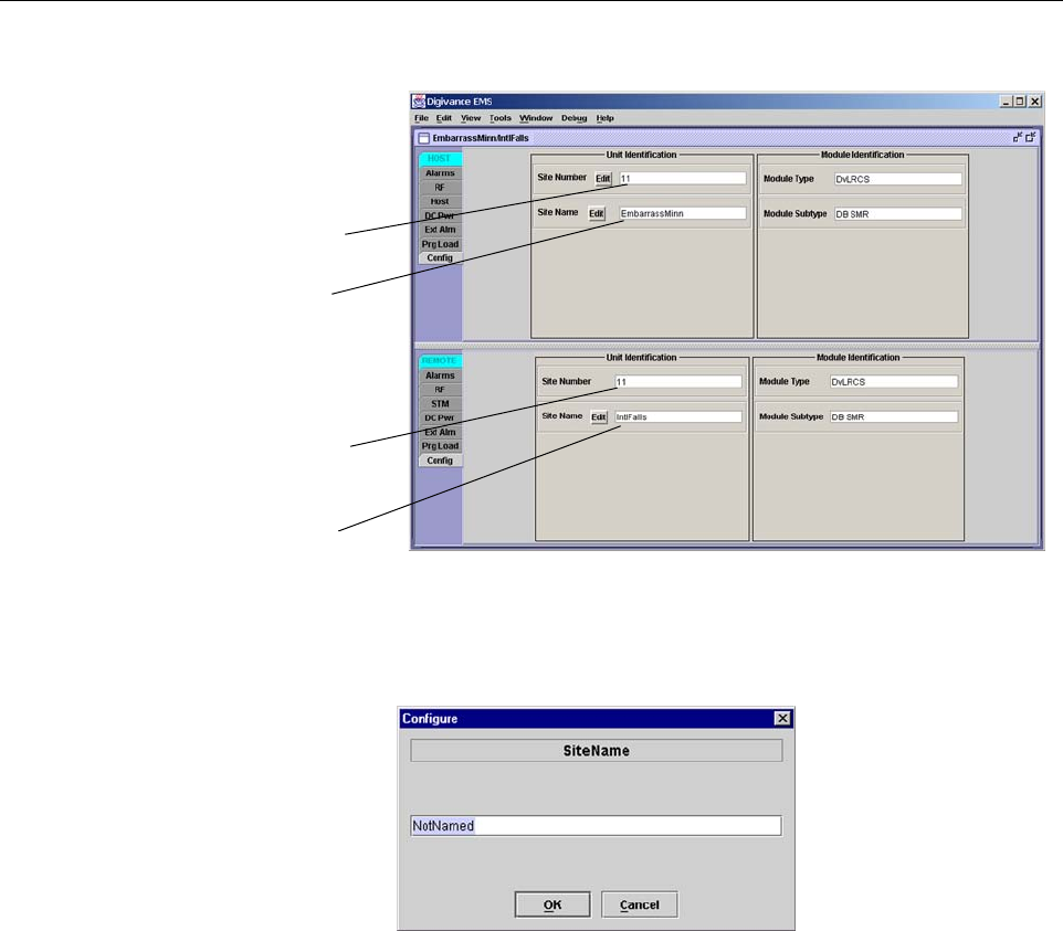
1. Click on the HOST Config tab and on the REMOTE Config tab. The HOST Config
display and the REMOTE Config display will open within the EMS main window as
shown in Figure 3-5.
2. Click on the HOST Site Name Edit button (see Figure 3-5). The Site Name pop-up
screen will open as shown in Figure 3-6. Enter a unique name for the HOST. The name
may be up to 32 characters long and must not contain any spaces. The name may include
numbers, punctuation, and upper or lower case letters and must always begin with a letter.
Click on OK to close the screen and make the changes take effect.
Note: If the input signal level is already –20 dBm, no external attenuator is required.
Caution: The Host Unit can be damaged if it is overdriven by the EBTS. Always install an
external protective attenuator at the Host Unit FWD RF IN port if the forward path composite
input signal level is greater than –9 dBm.
ADCP-75-187 • Preliminary Issue 1B • November 2005 • Section 3: OPERATION
Page 3-10
© 2005, ADC Telecommunications, Inc.
Figure 3-5. HOST and REMOTE Config Displays
Figure 3-6. HOST Site Name Pop-Up Screen
3. Click on the HOST Site Number Edit button (see Figure 3-5). The Site Number pop-up
screen will open. Enter any number (must be unique) between 1 and 24 and then click on
OK to close the screen and make the changes take effect.
4. Check the REMOTE Site Number field (see Figure 3-5). The REMOTE Site Number
does not have to be entered. When the HOST Site Number is entered, the system will
automatically enter the same number for the REMOTE Site Number.
5. Click on the REMOTE Site Name Edit button (see Figure 3-5). The Site Name pop-up
screen will open. Enter a unique name for the REMOTE. The name may be up to 32
characters long and must not contain any spaces. The name may include numbers,
punctuation, and upper or lower case letters and must always begin with a letter. Click on
OK to close the screen and make the changes take effect.
6. Open the Tools menu at the top of the main window and then select Refresh Catalog to
make the new Host and Remote site names appear in the View menu.
HOST Site Number
HOST Site Name
REMOTE Site Number
(Entered automatically
when the HOST site
number is selected)
REMOTE Site Name
Click on the Edit button
to open pop-up screen
ADCP-75-187 • Preliminary Issue 1B • November 2005 • Section 3: OPERATION
Page 3-11
© 2005, ADC Telecommunications, Inc.
2.3 Reference Procedure: Enter Host Forward Attenuation
The HU internal forward path attenuator setting determines the maximum composite output
signal level at the RU antenna port. The appropriate attenuation value for any particular system
is based on the number of channels the system is transporting and the signal level of the
composite forward path signals input at the host units RF IN ports. By default, the forward path
attenuator is set to 31 dB.
The maximum output power is 38.1 dBm (6.5 Watts) for 800 MHz and 800/900 MHz SMR
systems and 38.3 dBm (6.7 Watts) for 1900 MHz systems. The total forward path gain that is
provided by the system (with host and remote forward attenuators set to 0 dB) is 77.5 dBm for
800/900 MHz SMR systems, 78.1 for 800 MHz systems, and 78.3 for 1900 MHz systems. For
800/900 MHz SMR systems, this procedure sets the attenuation for both FORWARD RF IN ports.
Use the following procedure to set the forward path attenuation to provide the maximum
composite output signal level:
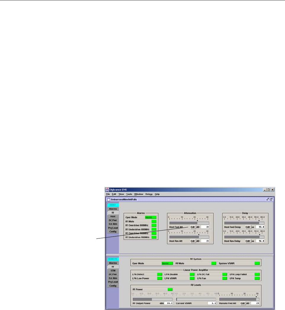
1. Click on the HOST RF tab. The HOST RF display will open within the EMS main
window as shown in Figure 3-7.
Figure 3-7. Typical HOST RF Display
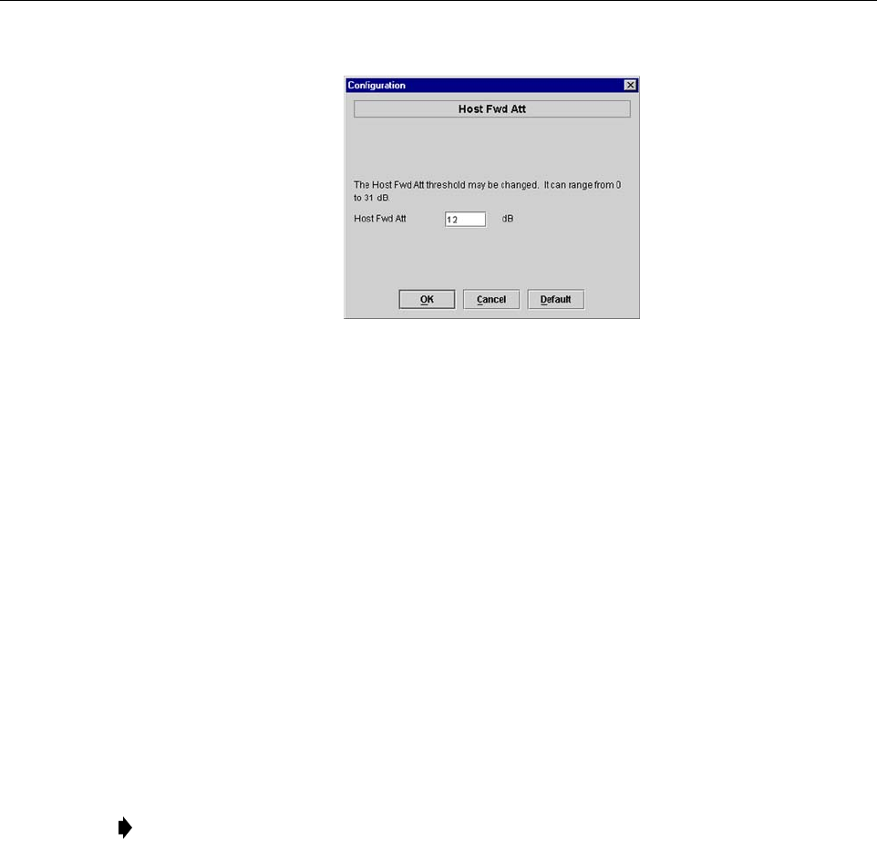
2. Click on the Host Fwd Att Edit button (see Figure 3-7). The Host Fwd Att pop-up screen
will open as shown in Figure 3-8.
3. Obtain the value of the total composite input signal level as determined in step 11 of
Section 2.1.
Click on Edit button
to open Host Fwd
Att pop-up screen
ADCP-75-187 • Preliminary Issue 1B • November 2005 • Section 3: OPERATION
Page 3-12
© 2005, ADC Telecommunications, Inc.
Figure 3-8. Host Fwd Att Pop-Up Screen
4. Determine the appropriate value to enter for the Host forward path attenuator by
subtracting the required system output level (per system design plan) from the system gain
(77.5 dB for 800/900 MHz SMR, 78.1 dB for 800 MHz, and 78.3 dB for 1900 MHz) and
then adding the composite input signal level. The result (see sample calculation) is the
amount of attenuation required.
Atten = (System Gain) – (Required System Output Power) + (Composite Input Power)
5. Enter the attenuation value and click OK to close the pop-up screen and to make the
changes take effect.
2.4 Reference Procedure: Determine Output Signal Level at RU Antenna Port
The RF output signal level should be measured at the RU ANTENNA port to verify that the
composite signal level is at the expected level. Use the following procedure to determine the
power level:
1. Place the AC circuit breaker switch (at the RU power panel) in the open (OFF) position.
2. Disconnect the antenna cable from the RU ANTENNA port.
3. Connect a spectrum analyzer or RF power meter to the HU ANTENNA port. (Check the
input rating of the test equipment. Insert a 30 dB 100 W attenuator if necessary.)
4. Place the AC circuit breaker switch (at the RU power panel) in the closed (ON) position.
5. If using a spectrum analyzer, proceed to step 6. If using a power meter, measure the
composite signal power from the RU and then proceed to step 8.
6. Measure the RF level of a single carrier, such as the control channel, in dBm. Make sure
the resolution bandwidth of the spectrum analyzer is 30 kHz.
Note: The RF output signal level measured in this procedure should be approximately
31 dBm less than the output level specified for operation. This is because the factory
default setting for the remote forward attenuator is 31 dB. The final adjustment of the
system RF output signal level will be completed in Section 2.5

ADCP-75-187 • Preliminary Issue 1B • November 2005 • Section 3: OPERATION
Page 3-13
© 2005, ADC Telecommunications, Inc.
7. Calculate the total composite signal power using the following formula:
Ptot = Pc + 10Log N
Where,
Ptot is the total composite power in dBm
Pc is the power per carrier in dBm as measured in step 6, and
N is the total number of channels.
8. Record the result measured in step 5 or calculated in step 7.
9. Place the AC circuit breaker switch (at the RU power panel) in the open (OFF) position.
10. Disconnect the spectrum analyzer or RF power meter from the HU ANTENNA port.
11. Re-connect the antenna cable to the HU ANTENNA port.
12. Place the AC circuit breaker switch (at the RU power panel) in the closed (ON) position.
2.5 Reference Procedure: Enter Remote Forward Attenuation
The RU internal forward path attenuator setting is used to reduce the power level of the
composite output signals at the RU. The maximum composite output signal level at the RU
antenna port is set using both the HU forward attenuator (see Section 2.3) and the RU forward
attenuator. Component variations may result in the output power at the HU antenna port being
slightly above or below the calculated value. The RU forward attenuator is used in conjunction
with the HU forward attenuator to add or remove attenuation to produce the required output
signal level at the antenna port. The default setting for the RU forward attenuator is 31 dB. Use
the following procedure to change the RU forward attenuation:
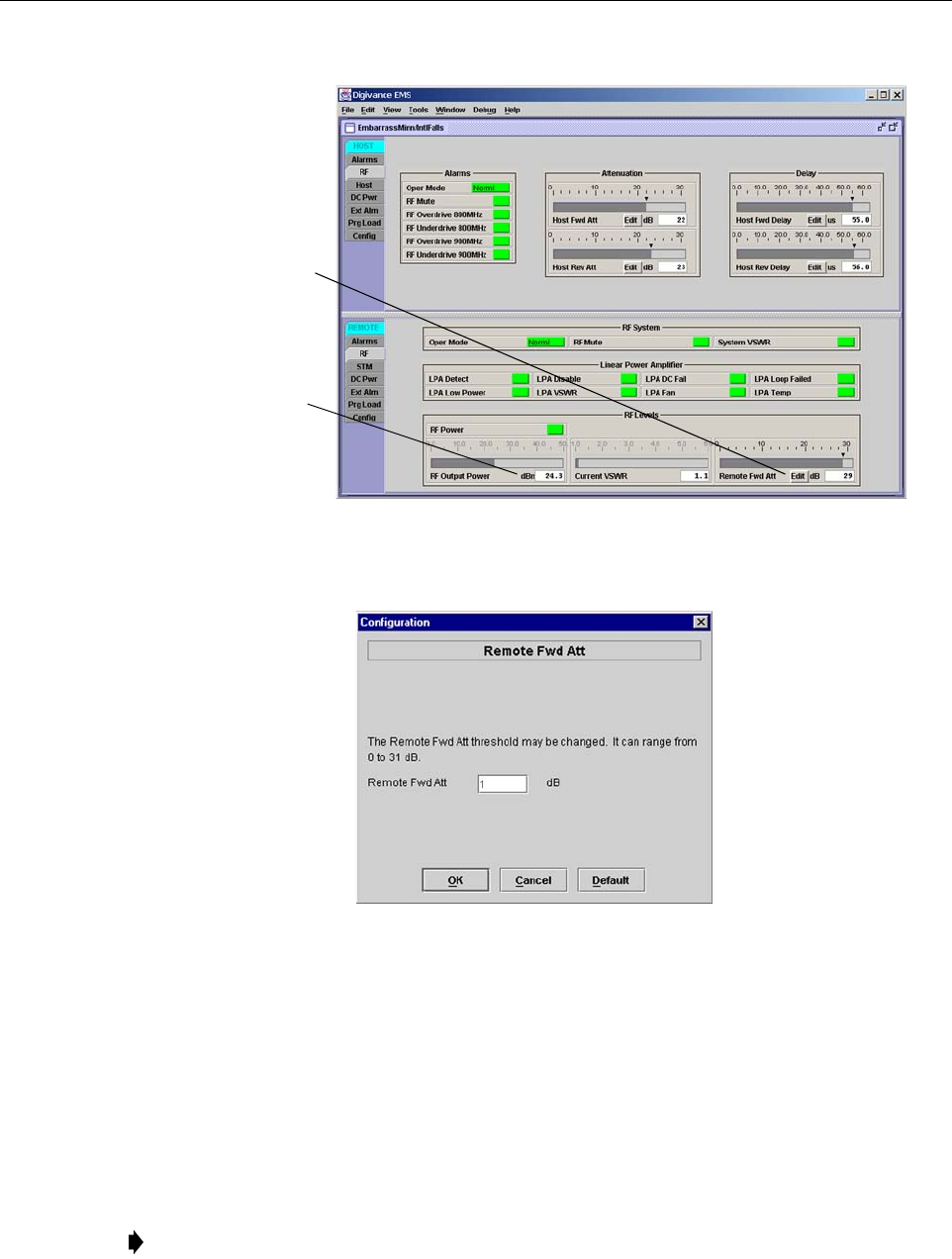
1. Click on the REMOTE RF tab. The REMOTE RF display will open within the EMS main
window as shown in Figure 3-9.
2. Check the level of the RF output signal (as determined in Section 2.4) against the system
design plan specifications. The maximum output signal level permitted is 38.1 dBm (6.5
Watts) for both 800 MHz and 800/1900 MHz SMR systems; and 38.3 dBm (6.7 Watts) for
1900 MHz systems.
3. Determine if more or less attenuation is required to produce the required output signal level.
4. Click on the Remote Fwd Att field Edit button (see Figure 3-9). The Remote Fwd Att
pop-up screen will open as shown in Figure 3-10.
Note: To comply with Maximum Permissible Exposure (MPE) requirements, the
maximum composite output from the antenna cannot exceed 1000 Watts EIRP and the
antenna must be permanently installed in a fixed location that provides at least 6 meters
(20 feet) of separation from all persons.
Caution: The RU may be destroyed if the maximum recommended output signal level at the RU
antenna port is exceeded. Make sure that sufficient attenuation is inserted in the forward path to
prevent the RU from being overdriven.
ADCP-75-187 • Preliminary Issue 1B • November 2005 • Section 3: OPERATION
Page 3-14
© 2005, ADC Telecommunications, Inc.
Figure 3-9. Typical REMOTE LPA Display
Figure 3-10. Remote Fwd Att Pop-Up Screen
5. Enter the required attenuation value and click OK to close the pop-up screen and to make
the changes take effect.
6. Verify that the appropriate RF output signal level appears in the RF Output Power field
(see Figure 3-9). This is primarily a reference value and should not take the place of
external test equipment when determining the power level of the composite RF output
signal. Depending on the modulation type and number of channels, the EMS software may
report a power level that is higher or lower (± 3 dB) than the actual RF output signal.
Note: To comply with Maximum Permissible Exposure (MPE) requirements, the
maximum composite output from the antenna cannot exceed 1000 Watts EIRP and the
antenna must be permanently installed in a fixed location that provides at least 6 meters
(20 feet) of separation from all persons.
Click Edit button to
open the Remote Fwd
Att pop-up screen
RF output signal
level (± 3 dB)

ADCP-75-187 • Preliminary Issue 1B • November 2005 • Section 3: OPERATION
Page 3-15
© 2005, ADC Telecommunications, Inc.
2.6 Reference Procedure: Enter Host Reverse Attenuation
The level of the RF signal that should be input to the EBTS will vary depending on the type of
EBTS, the receive distribution, and the number of channels present. To interface with the EBTS,
the reverse path signal level must be adjusted to provide the signal level required at the EBTS
input port(s). The HU provides from –1 to +30 dB of gain in the reverse path. By default, the
host reverse attenuator is set to –31 dB of attenuation which provides –1 dB of gain. Use the
following procedure to set the reverse path gain:
1. Check the EBTS manufacturer’s specifications to determine the composite signal level
required at the reverse path input port(s). Note that 800/900 MHz SMR host units have two
reverse path input ports.
2. Determine the overall gain and loss imposed on the signal by the antenna, antenna cable,
and by the cables that connect the HU to the EBTS.
3. Determine the amount of gain required to raise the reverse path signal to the level required
at the EBTS.
4. Click on the HOST RF tab. The HOST RF display will open within the EMS main
window as shown in Figure 3-11.
Figure 3-11. Typical HOST RF Display
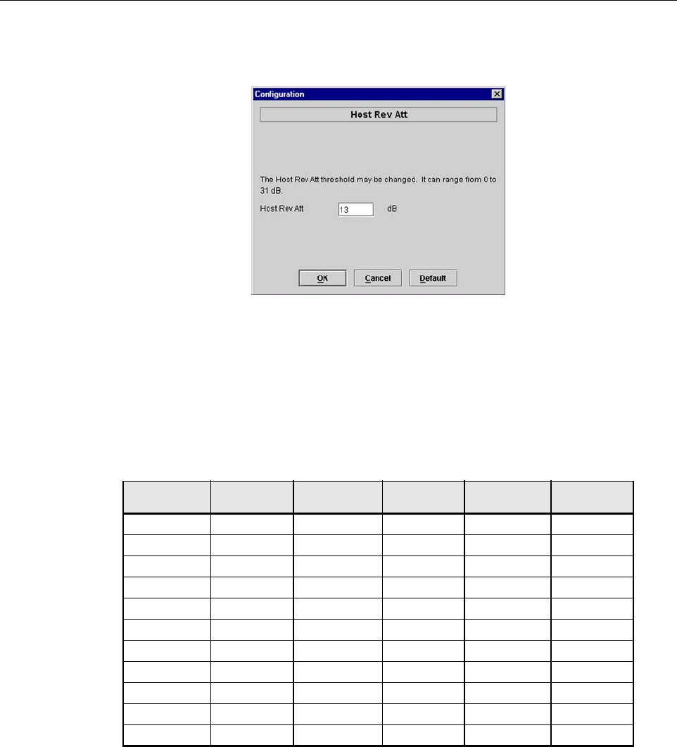
5. Click on the Host Rev Att field Edit button (see Figure 3-11). The Host Rev Att pop-up
screen will open as shown in Figure 3-12.
Click Edit button to
open the Host Rev Att
pop-up screen
ADCP-75-187 • Preliminary Issue 1B • November 2005 • Section 3: OPERATION
Page 3-16
© 2005, ADC Telecommunications, Inc.
Figure 3-12. Host Rev Att Pop-Up Screen
6. Enter the attenuation value that will provide the required gain. Refer to Table 3-2 for the
attenuation values and the corresponding gain (nominal) values.
7. Click OK to close the pop-up screen and to make the changes take effect.
2.7 Reference Procedure: Enter Host Forward and Reverse Delay
The forward and reverse delay function allows entry of from 0 to 63 µsec of delay in the
forward and reverse paths. This feature is used when multiple systems are used to transport the
same channel and there is a significant difference in the path delay between systems. Additional
delay may be entered to balance the overall system delay. The amount of delay required must be
calculated by the RF engineer and should be included in the system design plan. The default
setting is 0 µsec. Use the following procedure to change the forward and reverse path delay:
Table 3-2. Reverse Path Attenuation Setting and Nominal Gain Provided
ATTENUATION
SETTING
GAIN
PROVIDED
ATTENUATION
SETTING
GAIN
PROVIDED
ATTENUATION
SETTING
GAIN
PROVIDED
0 dB →30 dB 11 dB →19 dB 22 dB →8 dB
1 dB 29 dB 12 dB 18 dB 23 dB 7 dB
2 dB 28 dB 13 dB 17 dB 24 dB 6 dB
3 dB 27 dB 14 dB 16 dB 25 dB 5 dB
4 dB 26 dB 15 dB 15 dB 26 dB 4 dB
5 dB 25 dB 16 dB 14 dB 27 dB 3 dB
6 dB 24 dB 17 dB 13 dB 28 dB 2 dB
7 dB 23 dB 18 dB 12 dB 29 dB 1 dB
8 dB 22 dB 19 dB 11 dB 30 dB 0 dB
9 dB 21 dB 20 dB 10 dB 31 dB –1 dB
10 dB 20 dB 21 9 dB
ADCP-75-187 • Preliminary Issue 1B • November 2005 • Section 3: OPERATION
Page 3-17
© 2005, ADC Telecommunications, Inc.
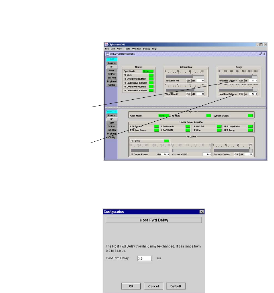
1. Click on the HOST RF tab. The HOST RF display will open within the EMS main
window as shown in Figure 3-13.
Figure 3-13. Typical HOST RF Display
2. Click on the Host Fwd Delay field Edit button (see Figure 3-13). The Host Fwd Delay
pop-up screen will open as shown in Figure 3-14.
Figure 3-14. Host Fwd Delay Pop-Up Screen
3. Obtain the value of the forward delay as specified in the system design plan. The delay is
adjustable in 0.1 µsec steps.
4. Enter the forward path delay value and click OK to close the pop-up screen and to make
the changes take effect.
5. Repeat the process for reverse delay by right-clicking on the appropriate delay section (see
Figure 3-13) and then entering the required delay value in the pop-up screen.
6. Click OK to close each pop-up screen and to make the changes take effect.
Click Edit button to
open the Host Fwd
Delay pop-up screen
Click Edit button to
open the Host Rev
Delay pop-up screen

ADCP-75-187 • Preliminary Issue 1B • November 2005 • Section 3: OPERATION
Page 3-18
© 2005, ADC Telecommunications, Inc.
Blank

ADCP-75-187 • Preliminary Issue 1B • November 2005 • Section 4: MAINTENANCE
Page 4-1
© 2005, ADC Telecommunications, Inc.
SECTION 4: MAINTENANCE
1 SYSTEM MAINTENANCE OVERVIEW . . . . . . . . . . . . . . . . . . . . . . . . . . . . . . . . . . . . . . . . . . . . . . . . . . . . . . . . . .4-1
1.1 Tools and Materials . . . . . . . . . . . . . . . . . . . . . . . . . . . . . . . . . . . . . . . . . . . . . . . . . . . . . . . . . . . . . . .4-1
2 FAULT DETECTION AND ALARM REPORTING . . . . . . . . . . . . . . . . . . . . . . . . . . . . . . . . . . . . . . . . . . . . . . . . . . . .4-2
3 FAULT ISOLATION AND TROUBLESHOOTING . . . . . . . . . . . . . . . . . . . . . . . . . . . . . . . . . . . . . . . . . . . . . . . . . . . .4-4
3.1 Host Unit Troubleshooting. . . . . . . . . . . . . . . . . . . . . . . . . . . . . . . . . . . . . . . . . . . . . . . . . . . . . . . . . . .4-5
3.2 RU Troubleshooting . . . . . . . . . . . . . . . . . . . . . . . . . . . . . . . . . . . . . . . . . . . . . . . . . . . . . . . . . . . . . . .4-7
4 TEST PROCEDURES . . . . . . . . . . . . . . . . . . . . . . . . . . . . . . . . . . . . . . . . . . . . . . . . . . . . . . . . . . . . . . . . . . . . 4-11
4.1 Optical Power Test. . . . . . . . . . . . . . . . . . . . . . . . . . . . . . . . . . . . . . . . . . . . . . . . . . . . . . . . . . . . . . . 4-11
4.2 Optical Loopback Test . . . . . . . . . . . . . . . . . . . . . . . . . . . . . . . . . . . . . . . . . . . . . . . . . . . . . . . . . . . . 4-13
5 SCHEDULED MAINTENANCE REQUIREMENTS . . . . . . . . . . . . . . . . . . . . . . . . . . . . . . . . . . . . . . . . . . . . . . . . . . 4-14
_________________________________________________________________________________________________________
1 SYSTEM MAINTENANCE OVERVIEW
This section explains the Digivance system fault detection and alarm reporting system, provides
a method for isolating and troubleshooting faults, and provides test procedures. The Digivance
system requires minimal regular maintenance to insure continuous and satisfactory operation.
The only components that require regular replacement are the HU cooling fans.
Maintenance also includes diagnosing and correcting service problems as they occur. When an
alarm is reported, it will be necessary to follow a systematic troubleshooting procedure to locate
the problem. Once the source of the problem is isolated, the appropriate corrective action can be
taken to restore service. The only internal components that can be replaced are the cooling fans
that mount in the HU. The failure of any other internal component will require replacement of
the entire unit.
1.1 Tools and Materials
The following tools and materials are required in order to complete the maintenance procedures
specified in this section:
• IR filtering safety glasses
• Patch cords with SC connectors
• 15 dB in-line SC optical attenuators
• Optical power meter (1550 and 1310 nm)
Content Page

ADCP-75-187 • Preliminary Issue 1B • November 2005 • Section 4: MAINTENANCE
Page 4-2
© 2005, ADC Telecommunications, Inc.
2 FAULT DETECTION AND ALARM REPORTING
The Digivance LRCS on-board embedded software detects various unit and system faults which
generate ether a Major or Minor alarm. A Major alarm indicates that the system has failed in a
way that directly affects RF transport performance. When a major alarm occurs, all RF
functions are disabled and the system is out of service. A Minor alarm means that system
performance is not affected or in some cases, that the performance may no longer be optimal.
When a minor alarm occurs, RF functions continue and the system remains in service.
The following means are used to report Major and Minor alarms:
• HU alarm contacts
• HU and RU LED’s
• EMS software Graphical User Interface (GUI)
• Network Operations Center - Network Element Manager (NOC/NEM) interface
• SNMP interface
The HU is equipped with a set of both normally open (NO) and normally closed (NC) alarm
contacts which may be used to report both Major and Minor alarms to an external alarm system.
The alarm contacts summarize the inputs so that any Major or Minor alarm will trigger an alarm
report to the external alarm system.
The HU is equipped with multiple front panel LED indicators that show status and alarm
information by displaying various colors: Green, Red, Yellow, and Off. The RU is equipped
with a single LED indicator that shows status and alarm information by displaying either Red or
Off. A detailed description of the Host Unit and Remote Unit LED indicators is provided
respectively in Table 4-1 and Table 4-2.
The EMS software GUI provides both a summary and a detailed list of alarm information that
includes unit and module level faults, circuit faults, and measured value faults such as voltages,
RF power, and temperature. A summary showing a list of all systems and their current alarm
status is presented through the Alarm OverView display. A more detailed list of alarm
information is presented through the HOST alarm display and the REMOTE alarm display. The
various fault conditions that trigger a major or minor alarm report are shown in the HOST and
REMOTE alarm displays.
The NOC/NEM interface provides the same summary and detailed listing of alarm information
as the EMS software GUI but in an ASCII text string format. Sending the command GET
ALARMSUMMARY produces a list of all systems and their current alarm status. Sending the
command GET ALARM ALL for a specific system will produce a detailed list of alarm
information for the specified system.
The SNMP interface provides alarm information to up to ten SNMP managers which must be
registered with the SNMP agent. The SNMP interface allows the SNMP managers to receive the
alarm and status information generated by the host and remote units. The presentation of the
alarm information is dependent on the features of the SNMP manager.

ADCP-75-187 • Preliminary Issue 1B • November 2005 • Section 4: MAINTENANCE
Page 4-3
© 2005, ADC Telecommunications, Inc.
Table 4-1. Host Unit LED Indicators
INDICATOR COLOR DESCRIPTION
POWER
Green
Off
Indicates if the HU is powered or un-powered.
The DC power source is on.
The DC power source is off.
STANDBY
Green (blinking)
Yellow (blinking)
Red (blinking)
Off
Indicates if the system is in the standby, normal, test, or
program load mode.
The HU is in the standby mode.
The HU is in the program load mode.
The HU is in the test mode.
The HU is in the normal mode.
HOST UNIT
Green
Ye l l ow
Red
Indicates if the HU is normal, over temperature, if an
internal fault is detected, or if there is an equipment mis-
match.
The HU is normal.
The HU is over temperature or detects an internal fault.
The HU detects an internal fault or HU/RU band mismatch.
REMOTE UNIT
Green
Ye l l ow
Red
Indicates if an alarm is detected at the RU.
No alarms detected at the RU.
A minor alarm is detected at the RU.
A major alarm is detected at the RU.
DRIVE 851–869
DRIVE 935–940
(Rear Access HU)
DRIVE
(Front Access HU)
Green
Ye l l ow
Red
Indicates if the specified forward path RF signal level is
normal, above overdrive threshold, or below underdrive
threshold.
The RF signal level is normal
The RF signal level is below the underdrive threshold.
The RF signal level is above the overdrive threshold.
FWD/REV
(PORT 1/PORT 2)
Green
Red
Indicates if the reverse path optical signals from the RU
are normal, if errors are detected, or if the optical signal is
not detected.
The reverse path optical signals are normal.
Excessive errors (see Note) are detected in the reverse path
optical signals or the HU is not receiving a reverse path optical
signal.
Note: Excessive errors means the Bit Error Rate (BER) has exceeded 10–6 (1 bit error per million bits).
Table 4-2. Remote Unit LED Indicator
INDICATOR COLOR DESCRIPTION
STATUS
Off
Red
Indicates if the RU is unpowered, normal, or if an internal
fault is detected.
The RU is unpowered or the RU is normal and no faults are
detected.
The RU detects an internal fault, excessive errors (see Note)
are detected in the forward path optical signals, or the RU is
not receiving a forward path optical signal.
Note: Excessive errors means the Bit Error Rate (BER) has exceeded 10–6 (1 bit error per million bits).
ADCP-75-187 • Preliminary Issue 1B • November 2005 • Section 4: MAINTENANCE
Page 4-4
© 2005, ADC Telecommunications, Inc.
3 FAULT ISOLATION AND TROUBLESHOOTING
Alarm information may be accessed using the HU and RU LED indicators, the EMS software
GUI, the NOC-NEM interface, or the SNMP manager. When an alarm occurs, use the unit LED
indicator(s) and any one of the specified software tools to determine which Digivance system is
affected, which unit (HU or RU) reported the alarm, and the fault that generated the alarm. Then
refer to either Section 3.1 Host Unit Troubleshooting or Section 3.2 RU Troubleshooting to
isolate the problem and to determine the corrective action required.
When attempting to isolate a problem, always determine the initial fault that generated the
alarm report. Some faults may cause additional faults to be reported which tends to obscure the
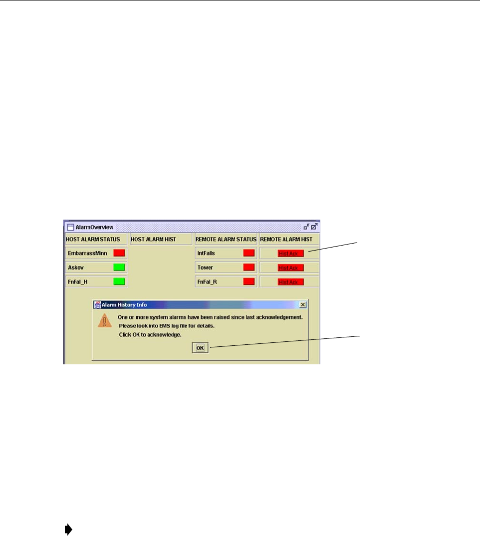
initial reason for the alarm. To help isolate faults, the EMS GUI provides an AlarmOverview
screen, shown in Figure 4-1, that indicates which Digivance system/unit is reporting the alarm.
Figure 4-1. AlarmOverView Screen
The AlarmOverview screen includes an ALARM HIST indicator which the user should click to
acknowledge that an alarm exists. Acknowledging the alarm opens the Alarm History Info
dialog box (also shown in Figure 4-1) which directs the user to view the EMS Log file for
details. The EMS Log file lists the various faults in the order in which they occurred. Clear each
fault starting with the initial fault. In most instances, clearing the initial fault will also clear any
remaining faults. For additional information on using the AlarmOverview screen, refer to the
Digivance Element Management System User Manual (see Related Publications section).
Note: It is recommended that if there are alarms at both the HU and RU, the optical faults
should be checked and cleared first. Because the HU and RU function as a system, a fault
in the fiber optic link will cause alarms to be reported by both the HU and RU.
Click to acknowledge
alarm and to open Alarm
History Info dialog box
Click to clear alarm
history fault indicator
and to close Alarm
History Info dialog box

ADCP-75-187 • Preliminary Issue 1B • November 2005 • Section 4: MAINTENANCE
Page 4-5
© 2005, ADC Telecommunications, Inc.
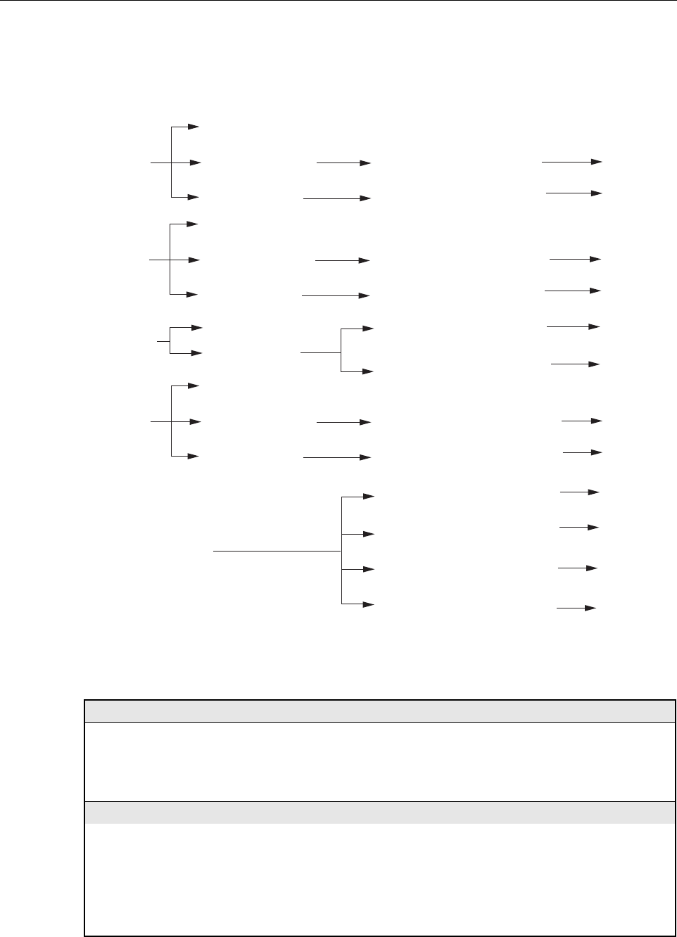
3.1 Host Unit Troubleshooting
Use this section to troubleshoot alarms that originate with the Host Unit. When a Minor alarm
occurs, one (or more) of the Host Unit LED’s with turn yellow and the EMS software will indicate
a minor fault/alarm. When a Major alarm occurs, one (or more) of the Host Unit LED’s will turn
red and the EMS software will report a major fault/alarm. Locate the LED and the corresponding
software fault/status indicator in Table 4-3 and then take the corrective action indicated.
Table 4-3. Host Unit Fault/Alarm Isolation Diagram
Power
Host Unit Front Panel LED
Standby
Host
Unit
Green - Normal
Yellow - Minor Alarm
Red - Major Alarm
Green - Powered
Off - Not powered
Green blinking - Standby
Yellow blinking -
Program load
Red blinking - Test
Off - Normal
Temperature - Over temperature
Fwd Synth Lock - Forward
synthesizer out of lock
LO Synth Lock - Local
oscillator synthesizer out of lock
Pri Rev Synth Lock - Reverse
primary synthesizer out of lock
8 Volt - Onboard 8 Volt power
supply below threshold
3.8 Volt - Onboard 3.8 Volt power
supply below threshold
Pri Fwd Mux Lock - Forward primary
phase locked loop out-of-lock
Pri Laser Fail - Forward primary
laser failure
Hardware mismatch - Host and
Remote band mismatch
Reverse Link Fault
Software Fault/Status Indicator
Replace HU
Table 4-5
Problem G
Table 4-5
Problem B
Replace HU or
RU with
correct unit
Corrective Action
or Reference
Oper Mode - Operational
mode of system
No specific HU faults - Only
faults with no associated LED
are displayed
Table 4-5
Problem A
Use EMS to
change system to
required mode
Continued
20013-B
Remote
Unit
Green - Normal
Yellow - Minor Alarm at Remote Unit - See Table 4-5. Remote Unit Fault/Alarm Isolation Diagram
Red - Major Alarm at Remote Unit - See Table 4-5. Remote Unit Fault/Alarm Isolation Diagram
ADCP-75-187 • Preliminary Issue 1B • November 2005 • Section 4: MAINTENANCE
Page 4-6
© 2005, ADC Telecommunications, Inc.
Table 4-4. Host Unit Fault/Alarm Corrective Action
PROBLEM A: The HU is not powered.
POSSIBLE CAUSE CORRECTIVE ACTION/COMMENTS
1. The HU is turned off.
2. The fuse is open/removed from the fuse panel
or the DC power has failed.
1. Place On/Off switch in the On position.
2. Check DC power source, repair as needed, and
replace or reinstall fuse at fuse panel.
PROBLEM B: The HU is overheating.
POSSIBLE CAUSE CORRECTIVE ACTION/COMMENTS
1. Air intake or exhaust opening to HU chassis
is blocked
2. Ambient temperature > 50º C/122º F.
3. Faulty fan.
4. The HU has failed.
1. Remove cause of air-flow blockage.
2. Reduce ambient temperature.
3. Replace HU fan (See applicable manual).
4. Replace HU.
Host Unit Front Panel LED Software Fault/Status Indicator Corrective Action
or Reference
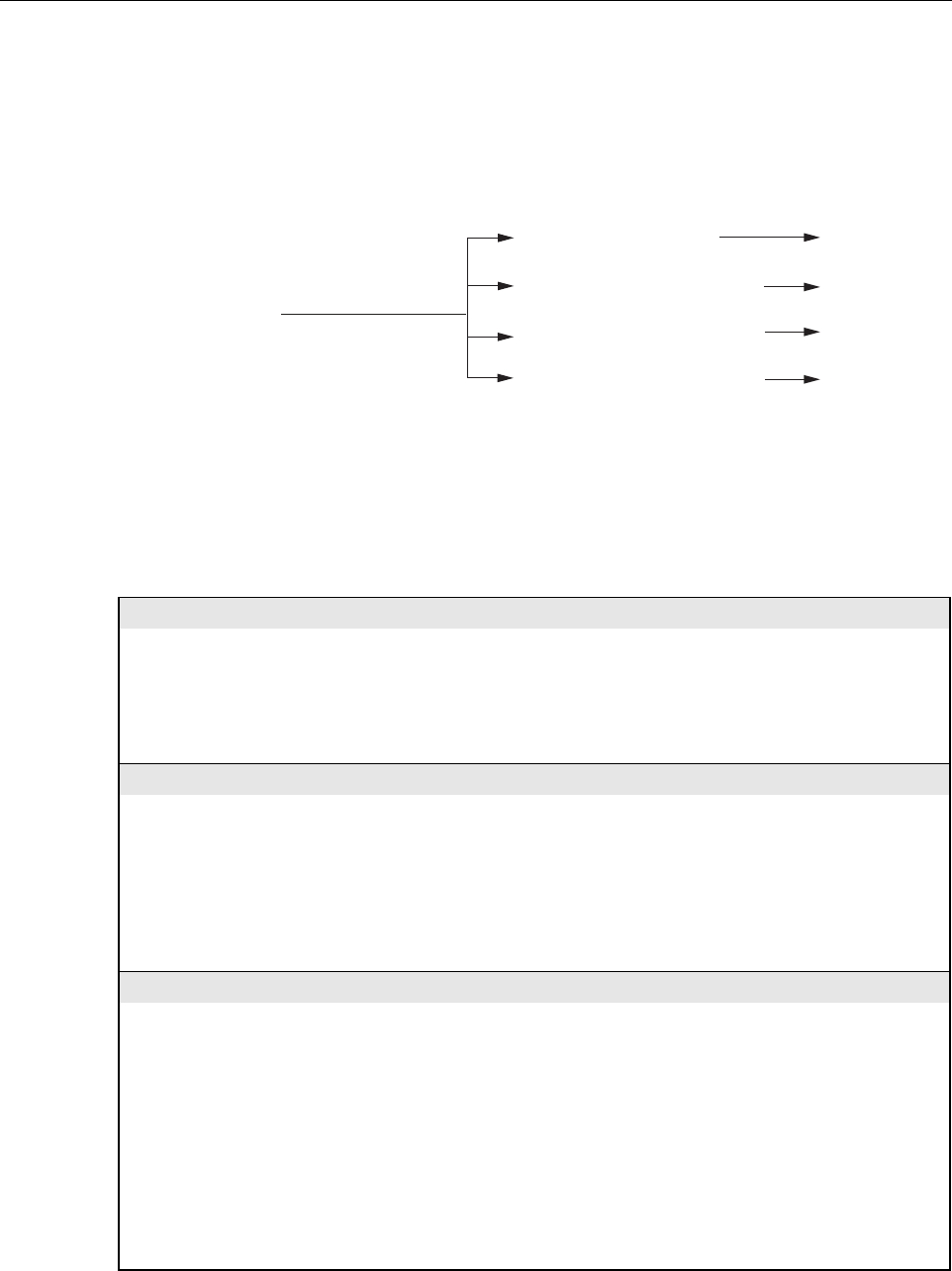
Table 4-3. Host Unit Fault/Alarm Isolation Diagram, continued
Fwd/Rev
(Port 1/Port 2)
See Table 4-4
Problem E
See Table 4-4
Problem E
Green - Normal
Red - Major Alarm
Pri Rx Light - No light received
over optical reverse path
Pri Rx Errors - Excessive errors
received over optical reverse path
See specific
fault indicator
See specific
fault indiator
Minor Contact Output - Minor alarm
reported by HU or STM
Major Contact Output - Major alarm
reported by HU or STM
Remote Lost - The HU cannot
communicate with remote (STM)
EMS Link Status - The EMS cannot
communicate with HU
No Associated LED
See Table 4-4
Problem E
See Table 4-4
Problem F
20583-A
Drive
851-869
(REAR
ACCESS)
Green - Normal
Yellow - Minor Alarm
Red - Major Alarm
RF Underdrive 800 MHz - 800 MHz
forward path RF signal level too low
RF Overdrive 800 MHz - 800 MHz
forward path RF signal level too high
Table 4-4
Problem C
Table 4-4
Problem D
Drive
935-940
(REAR
ACCESS)
Green - Normal
Yellow - Minor Alarm
Red - Major Alarm
RF Underdrive 900 MHz - 900 MHz
forward path RF signal level too low
RF Overdrive 900 MHz - 900 MHz
forward path RF signal level too high
Table 4-4
Problem C
Table 4-4
Problem D
Drive
(FRONT
ACCESS)
Green - Normal
Yellow - Minor Alarm
Red - Major Alarm
RF Underdrive - Forward path
RF signal level too low
RF Overdrive - Forward path
RF signal level too high
Table 4-4
Problem C
Table 4-4
Problem D

ADCP-75-187 • Preliminary Issue 1B • November 2005 • Section 4: MAINTENANCE
Page 4-7
© 2005, ADC Telecommunications, Inc.
3.2 RU Troubleshooting
Use this section to troubleshoot alarms that originate with the RU. When a Minor or Major
alarm occurs, the RU STATUS LED will turn red and the EMS software will indicate a minor or
major fault/alarm. Use the EMS software to identify the fault and then refer to Table 4-5 to
determine the corrective action required.
PROBLEM C: The RF input signal level is below the underdrive threshold.
POSSIBLE CAUSE CORRECTIVE ACTION/COMMENTS
1. Composite output signal from EBTS is too low.
2. Faulty coaxial connection between the HU
and the EBTS.
3. Incorrect attenuation in forward path RF
coaxial link.
1. Check EBTS composite output signal level and
adjust if too low.
2. Correct EBTS cables if faulty.
3. Check Host Forward Attenuator setting and
adjust if attenuation is too high.
PROBLEM D: The RF input signal is above the overdrive threshold.
POSSIBLE CAUSE CORRECTIVE ACTION/COMMENTS
1. Composite output signal level from EBTS is
too high.
2. Incorrect attenuation in forward path RF
coaxial link.
1. Check EBTS composite output signal level and
adjust if too high.
2. Check Forward Attenuator setting and adjust if
attenuation is too low.
PROBLEM E: No light received over the reverse path or excessive errors received over the reverse path
POSSIBLE CAUSE CORRECTIVE ACTION/COMMENTS
1. Faulty reverse path optical fiber.
2. Faulty optical transmit port at the RU;
or faulty optical receive port at the HU
1. Test optical fiber. Clean connector if dirty. Repair
or replace optical fiber if faulty. (See Section 4.1).
2. Test optical ports. Replace HU or RU if port is
faulty (See Section 4.2).
PROBLEM F: The HU does not respond to control or monitoring commands sent by the EMS.
POSSIBLE CAUSE CORRECTIVE ACTION/COMMENTS
1. The HU is not powered.
2. The cable connection between the HU and the
EMS computer is faulty.
3. The CAN cable connections between the HUs
in a multiple HU installation are faulty.
1. See Problem A this table.
2. Inspect EMS cable and repair or replace if faulty.
3. Inspect each CAN cable and repair or replace if
faulty.
PROBLEM G: There is a loss of gain in either the primary or diversity reverse path of 10 dBm or greater.
POSSIBLE CAUSE CORRECTIVE ACTION/COMMENTS
1. The HU has failed.
2. The RU has failed
1. Replace the HU.
2. Replace the RU.
Table 4-4. Host Unit Fault/Alarm Corrective Action, continued

ADCP-75-187 • Preliminary Issue 1B • November 2005 • Section 4: MAINTENANCE
Page 4-8
© 2005, ADC Telecommunications, Inc.
Table 4-5. Remote Unit Fault/Alarm Isolation Diagram
Remote Unit LED Software Fault/Status Indicator
Off - Not powered or Normal
No Response for
Minor Alarm
Red - Major Alarm
Temperature - Over temperature
Replace RU
See Table 4-6
Problem A
Corrective Action
or Reference
Converter - Power supply
converter failure
LO Synth Lock - Local
oscillator synthesizer out of lock
Fwd Synth Lock - Forward
synthesizer out of lock
Pri Rev Synth Lock - Reverse
primary synthesizer out of lock
Ref Synth Lock - Reference
synthesizer out of lock
8 Volt - Onboard 8 Volt power
supply below threshold
3.8 Volt - Onboard 3.8 Volt power
supply below threshold
Pri Rev Mux Lock - Reverse primary
phase locked loop out-of-lock
Pri Laser Fail - Reverse primary
laser failure
LPA DC Fail - LPAa
power supply failure
LPA Loop Fail - LPA
internal loop failure
LPA Low Power - LPA
internal amplifier failure
Continued 20584-B
See Table 4-6
Problem E
See Table 4-6
Problem E
See Table 4-6
Problem C
See Table 4-6
Problem B
See Table 4-6
Problem A
See Table 4-6
Problem D
Replace HU or
RU with
correct unit
LPA Temp - LPA over
temperature
LPA Over Power - LPA
signal level too high
LPA VSWR - The LPA
VSWR is too high
System VSWR - The VSWR at
the quadraplexer is too high
Pri Rx Light - No light received
over optical forward path
Pri Errors - Excessive errors
received over optical forward path
Hardware mismatch - Host and
Remote band mismatch
One LED, no
designation
ADCP-75-187 • Preliminary Issue 1B • November 2005 • Section 4: MAINTENANCE
Page 4-9
© 2005, ADC Telecommunications, Inc.
Table 4-6. Remote Unit Fault/Alarm Corrective Action
PROBLEM A: The RU (STM or LPA) is overheating.
POSSIBLE CAUSE CORRECTIVE ACTION/COMMENTS
1. Debris preventing air from freely circulating
around the RU aluminum enclosure.
2. Ambient temperature > 50º C/122º F.
3. The RU has failed.
1. Remove cause of air-flow blockage.
2. Reduce ambient temperature.
3. Replace RU.
PROBLEM B: The output power from the LPA exceeds the maximum rating.
POSSIBLE CAUSE CORRECTIVE ACTION/COMMENTS
1. The power level of the RF forward path
composite input signal at the HU is too high.
2. The RU (LPA) has failed.
1. Check the power level of the RF composite input
signal at the HU and adjust to correct level. To
reset, use EMS to place Digivance system in
standby mode and then place system back in
normal mode.
2. Replace RU.
PROBLEM C: The VSWR at the LPA exceeds the threshold setting of 3:1.
POSSIBLE CAUSE CORRECTIVE ACTION/COMMENTS
1. The antenna cable or antenna cable connectors
are faulty.
2. The antenna or antenna system is faulty.
3.The RU qudraplexer or LPA has failed.
1. Inspect antenna cable and connectors and repair
or replace as needed.To reset, use EMS to place
Digivance system in standby mode and then place
system back in normal mode.
2. Check the antenna circuit for shorts or opens
(including lightning protector). To reset, use EMS
to place Digivance system in standby mode and
then place system back in normal mode.
3. Replace RU.
Remote Unit LED Software Fault/Status Indicator Corrective Action
or Reference
Host Lost - The STM cannot
communicate with Host (HU)
EMS Link Status - The EMS cannot
communicate with STM
RF Power - No RF power detected
at quadraplexer (STM)
LPA Disable - The LPA is shut down
No Associated LED See Table 4-6
Problem G
See Table 4-6
Problem F
See Table 4-6
Problem E
See Table 4-6
Problem H
Table 4-5. Remote Unit Fault/Alarm Isolation Diagram, continued
20585-A

ADCP-75-187 • Preliminary Issue 1B • November 2005 • Section 4: MAINTENANCE
Page 4-10
© 2005, ADC Telecommunications, Inc.
PROBLEM D: The forward path VSWR is above threshold.
POSSIBLE CAUSE CORRECTIVE ACTION/COMMENTS
1. Faulty antenna or antenna system.
2. Faulty antenna cable.
3. The RU qudraplexer has failed.
1. Check the antenna system for shorts or opens
(including lightning protector). To reset, use
EMS to place Digivance system in standby mode
and then place system back in normal mode.
2. Check the antenna cable for faulty connections.
3. Replace the RU.
PROBLEM E: No light received over the forward path or excessive errors received over the forward path
POSSIBLE CAUSE CORRECTIVE ACTION/COMMENTS
1. Faulty forward path optical fiber.
2. Faulty optical transmit port at the HU;
or faulty optical receive port at the RU.
1. Test optical fiber. Clean connector if dirty. Repair
or replace optical fiber if faulty. (See Section 4.1).
2. Test optical ports. Replace HU or RU if port is
faulty (see Section 4.2).
PROBLEM F: The RU does not respond to control or monitoring commands sent by the EMS.
POSSIBLE CAUSE CORRECTIVE ACTION/COMMENTS
1. The cable connection between the HU and
the EMS computer is faulty.
1. Inspect EMS cable and repair or replace if faulty.
PROBLEM G: No RF power is detected at the RU quadraplexer.
POSSIBLE CAUSE CORRECTIVE ACTION/COMMENTS
1. No RF power is being input to the HU or the
RF input signal level at the HU is too low.
2. The RU (LPA) is faulty.
1. Check the RF input power level at the HU and
adjust until within specifications.
2. Replace RU.
PROBLEM H: The RF output form the RU (LPA) is shut down.
POSSIBLE CAUSE CORRECTIVE ACTION/COMMENTS
1. The LPA is in the forced shutdown mode.
2. The RU (LPA) is faulty.
1. Check for fault conditions that will cause a major
alarm. Correct faults as required. To reset, use
EMS to place Digivance system in standby mode
and then place system back in normal mode
2. Replace RU.
Table 4-6. Remote Unit Fault/Alarm Corrective Action, continued
ADCP-75-187 • Preliminary Issue 1B • November 2005 • Section 4: MAINTENANCE
Page 4-11
© 2005, ADC Telecommunications, Inc.
4 TEST PROCEDURES
This section provides procedures for common troubleshooting and maintenance tests. Refer to
these procedures as needed when specified in the Fault/Alarm Isolation Diagrams in Section 3.
4.1 Optical Power Test
A break in an optical fiber or a fault with the optical connector will interrupt communications
between linked components or generate excessive errors. Use the following procedure to isolate
a problem with an optical fiber or connector.
1. Put on the IR filtering safety glasses.
2. Notify the NOC or alarm monitoring system operator that the system is going offline.
3. At the HU, place the On/Off switch in the OFF position (press O). At the RU, place the
AC circuit breaker switch in the open (OFF) position.
4. Disconnect the optical fiber connectors for the fiber to be tested at the HU and the RU.
5. Inspect the optical connectors. Verify that connectors are clean and that no scratches or
imperfections are visible on the fiber end. Clean and polish the optical connectors if necessary.
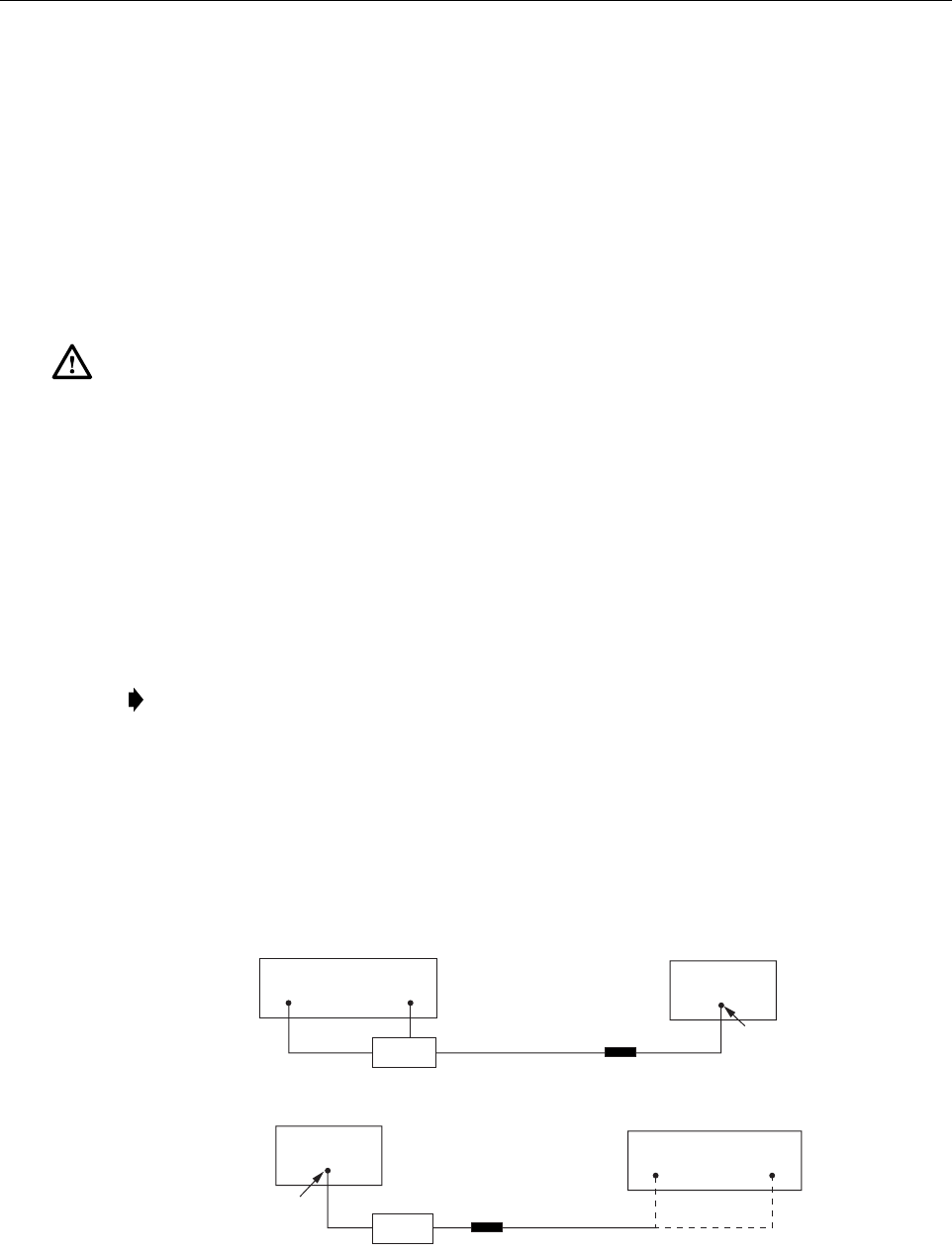
6. Connect the optical power meter to the output (receiver) end of the optical fiber as shown
in Figure 4-2. If an attenuator was included in the fiber link, make sure it is installed.
Figure 4-2. Forward and Reverse Path Optical Fiber Test Set Up
Danger: This equipment uses a Class 1 Laser according to FDA/CDRH rules. Laser radiation
can seriously damage the retina of the eye. Do not look into the ends of any optical fiber. Do not
look directly into the optical transmitter of any unit or exposure to laser radiation may result.
An optical power meter should be used to verify active fibers. A protective cap or hood MUST
be immediately placed over any radiating transmitter or optical fiber connector to avoid the
potential of dangerous amounts of radiation exposure. This practice also prevents dirt particles
from entering the connector.
Note: Turning off the HU and RU disables the respective lasers which is necessary in
order to safely inspect and clean the optical connectors.
HOST UNIT
FWD
(PORT 1)
REV
(PORT 2)
BAND 2 BAND 1
ATTENUATOR
(IF USED)
ATTENUATOR
(IF USED)
FWD/REV PATH
OPTICAL FIBER
FWD/REV PATH
OPTICAL FIBER
-15 TO -25 dBm
-15 TO -25 dBm
FORWARD PATH OPTICAL FIBER
TEST SET UP
REVERSE PATH
OPTICAL FIBER TEST SET UP
20979-A
REMOTE UNIT
OPTICAL POWER
METER
OPTICAL POWER
METER
WDM
WDM
23
3
SEE TAG ON PORT TO IDENTIFY SYSTEM
ADCP-75-187 • Preliminary Issue 1B • November 2005 • Section 4: MAINTENANCE
Page 4-12
© 2005, ADC Telecommunications, Inc.
7. Connect the input (transmitter) end of the optical fiber to the transmitting HU or RU.
8. If the transmitting unit is the HU, place the On/Off switch in the ON position (press I). If
the transmitting unit is the RU, close (turn on) the AC circuit breaker switch.
9. Using the transmitting HU or RU as an optical light source, measure the optical power at
the receiver end of the optical fiber. The power level of the optical signal received at the
HU or RU should be –15 to –25 dBm (with attenuator installed). If the power level of the
received optical signal is within this range, the optical fiber and the far end unit are good.
If the power level of the signal is greater than –15 dBm, insert additional attenuation to
bring the signal level within the specified range. If the power level is less than –25 dBm,
the value of the external attenuator is too high, the optical fiber is faulty, or the far end unit
optical transmitter is faulty. Continue with test procedure to isolate the problem
10. If the transmitting unit is the HU, place the On/Off switch in the OFF position (press O).
If the transmitting unit is the RU, open (turn off) the AC circuit breaker switch.
11. Disconnect the optical power meter from the receiver end of the optical fiber.
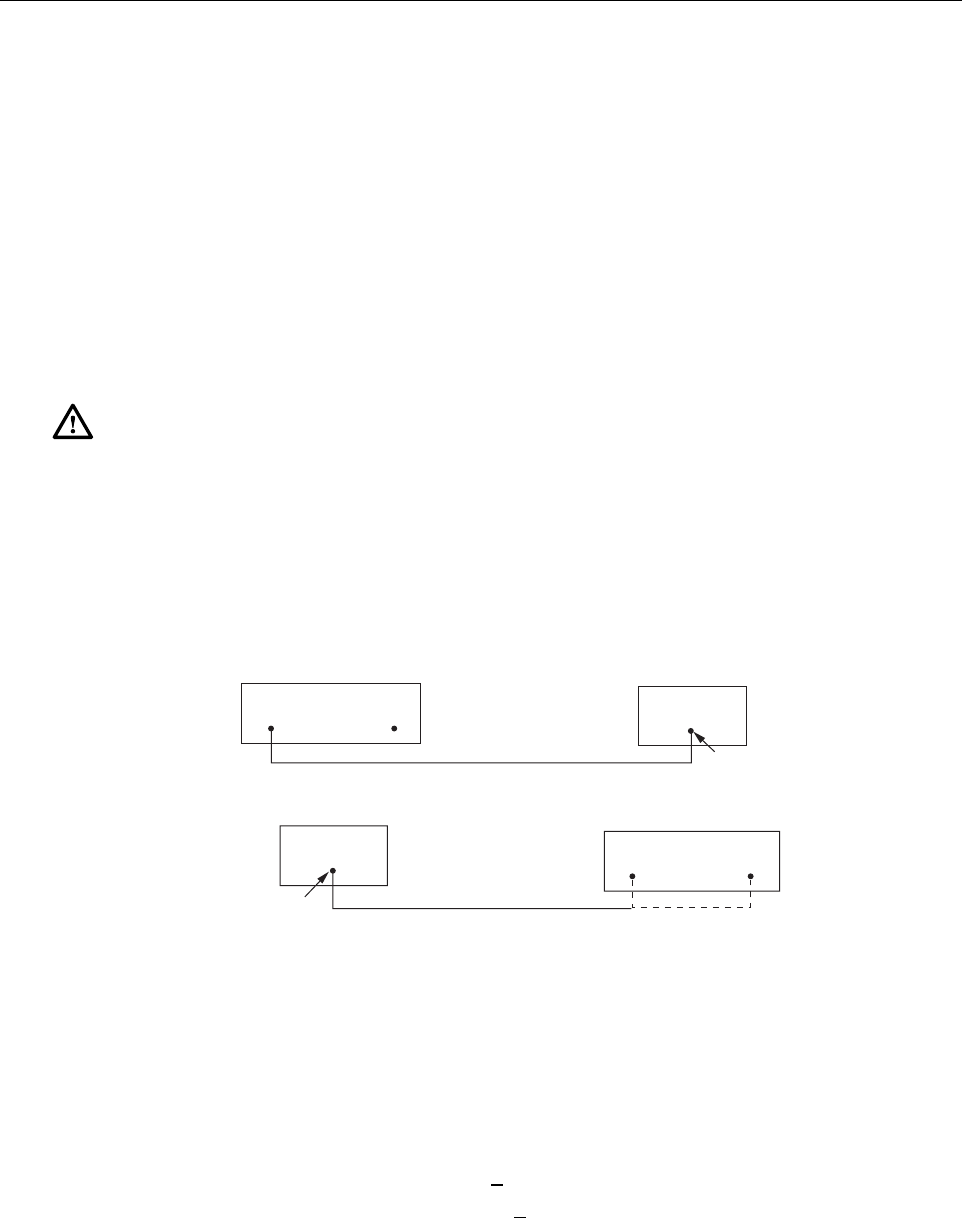
12. Use a 1 meter patch cord to connect the optical power meter to the transmitting HU or
RU as shown in Figure 4-3.
Figure 4-3. Host Unit and Remote Unit Optical Transmitter Test Set Up
13. If the transmitting unit is the HU, place the On/Off switch in the ON position (press I). If
the transmitting unit is the RU, close (turn on) the AC circuit breaker switch.
14. Measure the optical output power of the transmitting HU or RU. The power level of the
optical output signal from the HU or RU must meet the following specification:
Forward Path Signal at the HU: 0 + 1 dBm
Reverse Path Signal at the RU: +1.3 + 1 dBm
If the power level of the optical output signal is within specifications with a 1 meter patch
cord installed, the fiber optic link is faulty. If the power level of the optical signal is not
within specifications, the far end HU or RU optical transmitter is faulty.
Caution: Erratic operation may occur with an optical input signal level of –13 dBm or higher.
If the optical input signal level exceeds –9 dBm, the optical receiver may be damaged.
HOST UNIT
REMOTE UNIT
+1.3 +/- 1 dBm
0 +/- 1 dBm
HOST UNIT OPTICAL TRANSMITTER
TEST SET UP
REMOTE UNIT OPTICAL TRANSMITTER
TEST SET UP
1 METER PATCH CORD
1 METER PATCH CORD 20980-A
FWD
(PORT 1)
REV
(PORT 2)
BAND 2 BAND 1
OPTICAL POWER
METER
OPTICAL POWER
METER
SEE TAG ON PORT TO IDENTIFY SYSTEM

ADCP-75-187 • Preliminary Issue 1B • November 2005 • Section 4: MAINTENANCE
Page 4-13
© 2005, ADC Telecommunications, Inc.
15. If the transmitting unit is the HU, place the On/Off switch in the OFF position (press O).
If the transmitting unit is the RU, open (turn off) the AC circuit breaker switch.
16. Disconnect the optical power meter from the receiver end of the optical fiber.
17. Reconnect the optical fibers to the receiving HU or RU.
18. Repeat steps 3 through 17 for each optical fiber that requires testing.
19. When ready to put the system back into service, place the On/Off switch on the HU in the
ON position (press I) and close (turn on) the AC circuit breaker switch for the RU.
20. Notify the NOC or alarm monitoring service that the system is going back online.
4.2 Optical Loopback Test
The following procedure provides a test to determine if an optical port fault exists with the Host
Unit.
1. Put on the IR filtering safety glasses.
2. Notify the NOC or alarm monitoring system operator that the system is going offline.
3. Place the On/Off switch in the OFF position (press O).
4. Disconnect the optical fiber connectors from the FWD (PORT 1) and REV (PORT 2)
optical ports and place a dust cap over each connector.
5. Plug a 15 dB in-line optical attenuator into the FWD (PORT 1) optical port as shown in
Figure 4-4.
6. Connect a 1 meter patch cord between the optical attenuator and the REV (PORT 2)
optical port.
7. Place the On/Off switch in the ON position (press I).
Note: Because the RU is equipped with a WDM, the optical loopback test cannot be
performed on the RU.
Danger: This equipment uses a Class 1 Laser according to FDA/CDRH rules. Laser radiation
can seriously damage the retina of the eye. Do not look into the ends of any optical fiber. Do not
look directly into the optical transmitter of any unit or exposure to laser radiation may result.
An optical power meter should be used to verify active fibers. A protective cap or hood MUST
be immediately placed over any radiating transmitter or optical fiber connector to avoid the
potential of dangerous amounts of radiation exposure. This practice also prevents dirt particles
from entering the connector.
Caution: The optical receiver can be damaged if the power level of the optical input signal is
too high. To avoid damaging the optical receiver when performing the loopback test, always
install a 15 dB in-line attenuator in the optical receiver circuit.

ADCP-75-187 • Preliminary Issue 1B • November 2005 • Section 4: MAINTENANCE
Page 4-14
© 2005, ADC Telecommunications, Inc.
Figure 4-4. Host Unit Loopback Test
8. Observe the FWD/REV (PORT 1/PORT 2) LED indicator which will turn either red or
green. If the LED turns red, either the FWD (PORT 1) optical transmitter or the REV
(PORT 2) receiver is faulty. If the LED turns green, both the FWD (PORT 1) and the REV
(PORT 2) optical ports are good.
9. Place the On/Off switch in the OFF position (press O).
10. Remove the dust caps from the optical fiber connectors.
11. Clean each connector (follow connector supplier’s recommendations) and then insert each
connector into the appropriate optical port.
12. When ready to put the HU back into service, place the On/Off switch in the ON position
(press I).
13. Notify the NOC or alarm monitoring service that the system is going back online.
5 SCHEDULED MAINTENANCE REQUIREMENTS
The only scheduled maintenance required for the SCS system is to remove and replace the HU
cooling fans. This should be done at 60 month intervals. Refer to the applicable Digivance
LRCS Host Unit Installation and Maintenance Manual (See Related Publications section) for
the procedure.
HOST UNIT
1 METER PATCH CORD
15 dB
ATTENUATOR
20019-C
FWD
(PORT 1)
REV
(PORT 2)

ADCP-75-187 • Preliminary Issue 1B • November 2005 • Section 5: GENERAL INFORMATION
Page 5-1
© 2005, ADC Telecommunications, Inc.
SECTION 5: GENERAL INFORMATION
1 WARRANTY/SOFTWARE . . . . . . . . . . . . . . . . . . . . . . . . . . . . . . . . . . . . . . . . . . . . . . . . . . . . . . . . . . . . . . . . . .5-1
2 SOFTWARE SERVICE AGREEMENT. . . . . . . . . . . . . . . . . . . . . . . . . . . . . . . . . . . . . . . . . . . . . . . . . . . . . . . . . . .5-1
3 REPAIR/EXCHANGE POLICY . . . . . . . . . . . . . . . . . . . . . . . . . . . . . . . . . . . . . . . . . . . . . . . . . . . . . . . . . . . . . . .5-1
4 REPAIR CHARGES . . . . . . . . . . . . . . . . . . . . . . . . . . . . . . . . . . . . . . . . . . . . . . . . . . . . . . . . . . . . . . . . . . . . . .5-2
5 REPLACEMENT/SPARE PRODUCTS . . . . . . . . . . . . . . . . . . . . . . . . . . . . . . . . . . . . . . . . . . . . . . . . . . . . . . . . . .5-2
6 RETURNED MATERIAL . . . . . . . . . . . . . . . . . . . . . . . . . . . . . . . . . . . . . . . . . . . . . . . . . . . . . . . . . . . . . . . . . . .5-2
7 CUSTOMER INFORMATION AND ASSISTANCE . . . . . . . . . . . . . . . . . . . . . . . . . . . . . . . . . . . . . . . . . . . . . . . . . . .5-3
_________________________________________________________________________________________________________
1 WARRANTY/SOFTWARE
The Product and Software warranty policy and warranty period for all ADC Products is
published in ADC’s Warranty/Software Handbook. Contact the Technical Assistance Center at
1-800-366-3891, extension 73476 (in U.S.A. or Canada) or 952-917-3476 (outside U.S.A. and
Canada) for warranty or software information or for a copy of the Warranty/Software
Handbook.
2 SOFTWARE SERVICE AGREEMENT
ADC software service agreements for some ADC Products are available at a nominal fee.
Contact the Technical Assistance Center at 1-800-366-3891, extension 73476 (in U.S.A. or
Canada) or 952-917-3476 (outside U.S.A. and Canada) for software service agreement
information.
3 REPAIR/EXCHANGE POLICY
All repairs of ADC Products must be done by ADC or an authorized representative. Any
attempt to repair or modify ADC Products without written authorization from ADC voids the
warranty.
If a malfunction cannot be resolved by the normal troubleshooting procedures, call the
Technical Assistance Center at 1-800-366-3891, extension 73476 (in U.S.A. or Canada) or
952-917-3476 (outside U.S.A. and Canada). A telephone consultation can sometimes resolve a
problem without the need to repair or replace the ADC Product.
If, during a telephone consultation, ADC determines the ADC Product needs repair, ADC will
authorize the return of the affected Product for repair and provide a Return Material
Authorization number and complete return shipping instructions. If time is critical, ADC can
arrange to ship the replacement Product immediately. In all cases, the defective Product must be
carefully packaged and returned to ADC.
Content Page

ADCP-75-187 • Preliminary Issue 1B • November 2005 • Section 5: GENERAL INFORMATION
Page 5-2
© 2005, ADC Telecommunications, Inc.
4 REPAIR CHARGES
If the defect and the necessary repairs are covered by the warranty, and the applicable warranty
period has not expired, the Buyer’s only payment obligation is to pay the shipping cost to return
the defective Product. ADC will repair or replace the Product at no charge and pay the return
shipping charges.
Otherwise, ADC will charge a percentage of the current Customer Product price for the repair
or NTF (No Trouble Found). If an advance replacement is requested, the full price of a new unit
will be charged initially. Upon receipt of the defective Product, ADC will credit Buyer with 20
percent of full price charged for any Product to be Out-of-Warranty. Products must be returned
within thirty (30) days to be eligible for any advance replacement credit. If repairs necessitate a
visit by an ADC representative, ADC will charge the current price of a field visit plus round trip
transportation charges from Minneapolis to the Buyer’s site.
5 REPLACEMENT/SPARE PRODUCTS
Replacement parts, including, but not limited to, button caps and lenses, lamps, fuses, and patch
cords, are available from ADC on a special order basis. Contact the Technical Assistance Center
at 1-800-366-3891, extension 73476 (in U.S.A. or Canada) or 952-917-3476 (outside U.S.A.
and Canada) for additional information.
Spare Products and accessories can be purchased from ADC. Contact Sales Administration at
1-800-366-3891, extension 73000 (in U.S.A. or Canada) or 1-952-938-8080 (outside U.S.A.
and Canada) for a price quote and to place your order.
6 RETURNED MATERIAL
Contact the ADC Product Return Department at 1-800-366-3891, extension 73748 (in U.S.A. or
Canada) or 952-917-3748 (outside U.S.A. and Canada) to obtain a Return Material
Authorization number prior to returning an ADC Product.
All returned Products must have a Return Material Authorization (RMA) number clearly
marked on the outside of the package. The Return Material Authorization number is valid for 90
days from authorization.
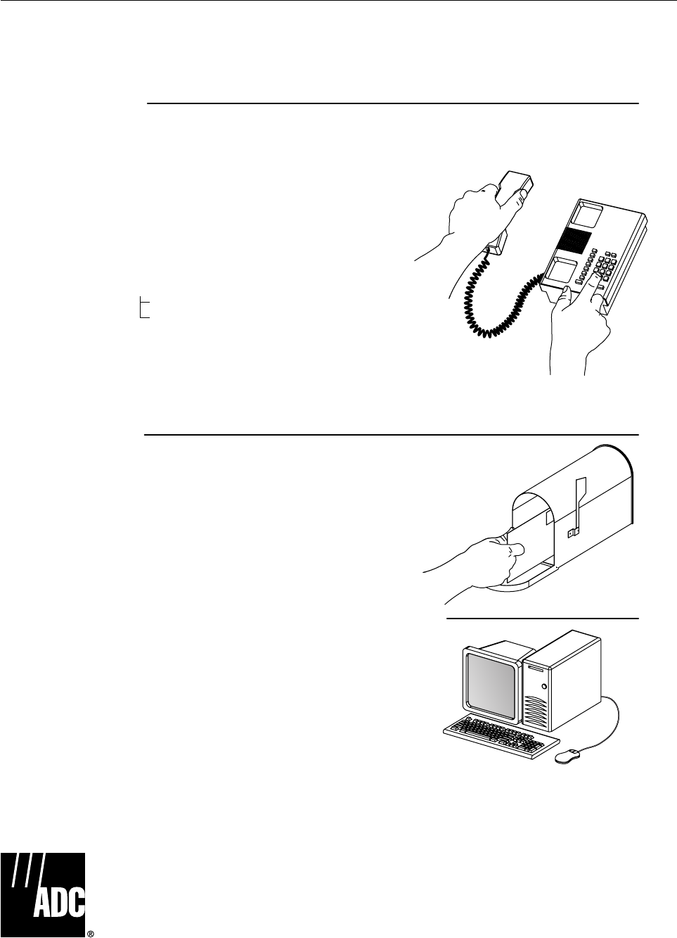
Page 5-3
ADCP-75-187 • Preliminary Issue 1B • November 2005 • Section 5: GENERAL INFORMATION
7 CUSTOMER INFORMATION AND ASSISTANCE
© 2005, ADC Telecommunications, Inc.
All Rights Reserved
Printed in U.S.A
13944-M
WRITE:
ADC TELECOMMUNICATIONS, INC
PO BOX 1101,
MINNEAPOLIS, MN 55440-1101, USA
ADC TELECOMMUNICATIONS (S'PORE) PTE. LTD.
100 BEACH ROAD, #18-01, SHAW TOWERS.
SINGAPORE 189702.
ADC EUROPEAN CUSTOMER SERVICE, INC
BELGICASTRAAT 2,
1930 ZAVENTEM, BELGIUM
PHONE:
EUROPE
Sales Administration: +32-2-712-65 00
Technical Assistance: +32-2-712-65 42
EUROPEAN TOLL FREE NUMBERS
UK: 0800 960236
Spain: 900 983291
France: 0800 914032
Germany: 0180 2232923
U.S.A. OR CANADA
Sales: 1-800-366-3891 Extension 73000
Technical Assistance: 1-800-366-3891
Connectivity Extension 73475
Wireless Extension 73476
ASIA/PACIFIC
Sales Administration: +65-6294-9948
Technical Assistance: +65-6393-0739
ELSEWHERE
Sales Administration: +1-952-938-8080
Technical Assistance: +1-952-917-3475
Italy: 0800 782374
PRODUCT INFORMATION AND TECHNICAL ASSISTANCE:
Contents herein are current as of the date of publication. ADC reserves the right to change the contents without prior notice.
In no event shall ADC be liable for any damages resulting from loss of data, loss of use, or loss of profits and ADC further
disclaims any and all liability for indirect, incidental, special, consequential or other similar damages. This disclaimer of
liability applies to all products, publications and services during and after the warranty period. This publication may be
verified at any time by contacting ADC's Technical Assistance Center.
euro.tac@adc.com
asiapacific.tac@adc.com
wireless.tac@adc.com
connectivity.tac@adc.com
Blank

i
www.adc.com