ADC Telecommunications DSC1901A Digivance SCS 1900 MHz Booster System User Manual 75187
ADC Telecommunications Inc Digivance SCS 1900 MHz Booster System 75187
Contents
- 1. Users Manual Part 1
- 2. Users Manual Part 2
- 3. Users Manual page ix Revised
- 4. Users Manual Page 2 26 Revised
Users Manual Part 1
ADCP-75-187
Preliminary Issue 1B
November 2005
1346357 Rev 1
Digivance® Street-Level Coverage Solution
800 MHz, 1900 MHz, and 800/900 MHz SMR
System Operation and Maintenance Manual
20576-A

ADCP-75-187
Preliminary Issue 1B
November 2005
1346357 Rev 1
Digivance® Street-Level Coverage Solution
800 HHz, 1900 MHz, 800/900 MHz SMR
System Operation and Maintenance Manual

ADCP-75-187 • Preliminary Issue 1B • November 2005 • Preface
Page ii
COPYRIGHT
© 2005, ADC Telecommunications, Inc.
All Rights Reserved
Printed in the U.S.A.
REVISION HISTORY
LIST OF CHANGES
The technical changes incorporated into this issue are listed below.
TRADEMARK INFORMATION
ADC and Digivance are registered trademarks of ADC Telecommunications, Inc.
OptiTap is a trademark of Corning Incorporated.
Stargazer is a registered trademark of ADC DSL Systems, Inc.
Procomm Plus is a registered trademark of Quarterdeck Corporation.
Acrobat and Adobe are registered trademarks of Adobe Systems, Inc.
DISCLAIMER OF LIABILITY
Contents herein are current as of the date of publication. ADC reserves the right to change the contents without prior notice. In no
event shall ADC be liable for any damages resulting from loss of data, loss of use, or loss of profits and ADC further
disclaims any and all liability for indirect, incidental, special, consequential or other similar damages. This disclaimer of
liability applies to all products, publications and services during and after the warranty period.
This publication may be verified at any time by contacting ADC’s Technical Assistance Center at 1-800-366-3891, extension 73476
(in U.S.A. or Canada) or 952-917-3476 (outside U.S.A. and Canada), or by e-mail to wireless.tac@adc.com
ISSUE DATE REASON FOR CHANGE
1B 011/2005 Original issue.
PAGE IDENTIFIER DESCRIPTION OF CHANGE
All Original issue.
ADC Telecommunications, Inc.
P.O. Box 1101, Minneapolis, Minnesota 55440-1101
In U.S.A. and Canada: 1-800-366-3891
Outside U.S.A. and Canada: (952) 938-8080
Fax: (952) 917-1717

ADCP-75-187 • Preliminary Issue 1B • November 2005 • Preface
Page iii
© 2005, ADC Telecommunications, Inc.
TABLE OF CONTENTS
Content Page
ABOUT THIS MANUAL . . . . . . . . . . . . . . . . . . . . . . . . . . . . . . . . . . . . . . . . . . . . . . . . . . . . . . . . . . . . . . . . . . . . . . . . vii
RELATED PUBLICATIONS . . . . . . . . . . . . . . . . . . . . . . . . . . . . . . . . . . . . . . . . . . . . . . . . . . . . . . . . . . . . . . . . . . . . . . vii
ADMONISHMENTS . . . . . . . . . . . . . . . . . . . . . . . . . . . . . . . . . . . . . . . . . . . . . . . . . . . . . . . . . . . . . . . . . . . . . . . . . .viii
GENERAL SAFETY PRECAUTIONS . . . . . . . . . . . . . . . . . . . . . . . . . . . . . . . . . . . . . . . . . . . . . . . . . . . . . . . . . . . . . . . . viii
STANDARDS CERTIFICATION . . . . . . . . . . . . . . . . . . . . . . . . . . . . . . . . . . . . . . . . . . . . . . . . . . . . . . . . . . . . . . . . . . . .ix
LIST OF ACRONYMS AND ABBREVIATIONS . . . . . . . . . . . . . . . . . . . . . . . . . . . . . . . . . . . . . . . . . . . . . . . . . . . . . . . . . . .ix
SECTION 1:
OVERVIEW
1 INTRODUCTION. . . . . . . . . . . . . . . . . . . . . . . . . . . . . . . . . . . . . . . . . . . . . . . . . . . . . . . . . . . . . . . . . . . . . . . .1-1
2 SCS SYSTEM OVERVIEW . . . . . . . . . . . . . . . . . . . . . . . . . . . . . . . . . . . . . . . . . . . . . . . . . . . . . . . . . . . . . . . . .1-1
2.1 Basic SCS System Components . . . . . . . . . . . . . . . . . . . . . . . . . . . . . . . . . . . . . . . . . . . . . . . . . . . . . . .1-1
2.2 Enhanced Base Transceiver Station Interface. . . . . . . . . . . . . . . . . . . . . . . . . . . . . . . . . . . . . . . . . . . . . .1-3
2.3 Subscriber Unit Interface . . . . . . . . . . . . . . . . . . . . . . . . . . . . . . . . . . . . . . . . . . . . . . . . . . . . . . . . . . .1-3
2.4 Local Management Interface. . . . . . . . . . . . . . . . . . . . . . . . . . . . . . . . . . . . . . . . . . . . . . . . . . . . . . . . .1-3
2.5 Network Operations Center Interface . . . . . . . . . . . . . . . . . . . . . . . . . . . . . . . . . . . . . . . . . . . . . . . . . . .1-5
2.6 SNMP Interface . . . . . . . . . . . . . . . . . . . . . . . . . . . . . . . . . . . . . . . . . . . . . . . . . . . . . . . . . . . . . . . . . .1-6
3 SYSTEM FUNCTIONS AND FEATURES. . . . . . . . . . . . . . . . . . . . . . . . . . . . . . . . . . . . . . . . . . . . . . . . . . . . . . . . .1-7
3.1 Fiber Optic Transport . . . . . . . . . . . . . . . . . . . . . . . . . . . . . . . . . . . . . . . . . . . . . . . . . . . . . . . . . . . . . .1-7
3.2 Control and Monitoring Software . . . . . . . . . . . . . . . . . . . . . . . . . . . . . . . . . . . . . . . . . . . . . . . . . . . . . .1-8
3.3 Fault Detection and Alarm Reporting . . . . . . . . . . . . . . . . . . . . . . . . . . . . . . . . . . . . . . . . . . . . . . . . . . .1-8
3.4 Powering . . . . . . . . . . . . . . . . . . . . . . . . . . . . . . . . . . . . . . . . . . . . . . . . . . . . . . . . . . . . . . . . . . . . . .1-8
3.5 Equipment Mounting and Location . . . . . . . . . . . . . . . . . . . . . . . . . . . . . . . . . . . . . . . . . . . . . . . . . . . . .1-8
4 DUAL-BAND REMOTE UNIT SCS SYSTEMS . . . . . . . . . . . . . . . . . . . . . . . . . . . . . . . . . . . . . . . . . . . . . . . . . . . . .1-9
SECTION 2:
DESCRIPTION
1 INTRODUCTION. . . . . . . . . . . . . . . . . . . . . . . . . . . . . . . . . . . . . . . . . . . . . . . . . . . . . . . . . . . . . . . . . . . . . . . .2-2
2 HOST UNIT . . . . . . . . . . . . . . . . . . . . . . . . . . . . . . . . . . . . . . . . . . . . . . . . . . . . . . . . . . . . . . . . . . . . . . . . . . .2-2
2.1 Primary Components . . . . . . . . . . . . . . . . . . . . . . . . . . . . . . . . . . . . . . . . . . . . . . . . . . . . . . . . . . . . . .2-2
2.2 Mounting . . . . . . . . . . . . . . . . . . . . . . . . . . . . . . . . . . . . . . . . . . . . . . . . . . . . . . . . . . . . . . . . . . . . . .2-2
2.3 Fault Detection and Alarm Reporting . . . . . . . . . . . . . . . . . . . . . . . . . . . . . . . . . . . . . . . . . . . . . . . . . . .2-3
2.4 RF Signal Connections . . . . . . . . . . . . . . . . . . . . . . . . . . . . . . . . . . . . . . . . . . . . . . . . . . . . . . . . . . . . .2-4
2.5 RF Signal Level Adjustments. . . . . . . . . . . . . . . . . . . . . . . . . . . . . . . . . . . . . . . . . . . . . . . . . . . . . . . . .2-4
2.6 Propagation Delay . . . . . . . . . . . . . . . . . . . . . . . . . . . . . . . . . . . . . . . . . . . . . . . . . . . . . . . . . . . . . . . .2-4
2.7 Optical Connection . . . . . . . . . . . . . . . . . . . . . . . . . . . . . . . . . . . . . . . . . . . . . . . . . . . . . . . . . . . . . . .2-4
2.8 Controller Area Network Interface Connection . . . . . . . . . . . . . . . . . . . . . . . . . . . . . . . . . . . . . . . . . . . . .2-5
2.9 Service Interface Connection. . . . . . . . . . . . . . . . . . . . . . . . . . . . . . . . . . . . . . . . . . . . . . . . . . . . . . . . .2-5
2.10 Powering . . . . . . . . . . . . . . . . . . . . . . . . . . . . . . . . . . . . . . . . . . . . . . . . . . . . . . . . . . . . . . . . . . . . . .2-5
2.11 Cooling . . . . . . . . . . . . . . . . . . . . . . . . . . . . . . . . . . . . . . . . . . . . . . . . . . . . . . . . . . . . . . . . . . . . . . .2-5

ADCP-75-187 • Preliminary Issue 1B • November 2005 • Preface
Page iv
© 2005, ADC Telecommunications, Inc.
TABLE OF CONTENTS
Content Page
2.12 User Interface. . . . . . . . . . . . . . . . . . . . . . . . . . . . . . . . . . . . . . . . . . . . . . . . . . . . . . . . . . . . . . . . . . . 2-5
3 REMOTE UNIT . . . . . . . . . . . . . . . . . . . . . . . . . . . . . . . . . . . . . . . . . . . . . . . . . . . . . . . . . . . . . . . . . . . . . . . . 2-9
3.1 Primary Components . . . . . . . . . . . . . . . . . . . . . . . . . . . . . . . . . . . . . . . . . . . . . . . . . . . . . . . . . . . . . . 2-9
3.2 Mounting . . . . . . . . . . . . . . . . . . . . . . . . . . . . . . . . . . . . . . . . . . . . . . . . . . . . . . . . . . . . . . . . . . . . . 2-10
3.3 Fault Detection and Alarm Reporting . . . . . . . . . . . . . . . . . . . . . . . . . . . . . . . . . . . . . . . . . . . . . . . . . . 2-10
3.4 Antenna Cable Connection . . . . . . . . . . . . . . . . . . . . . . . . . . . . . . . . . . . . . . . . . . . . . . . . . . . . . . . . . 2-11
3.5 RF Signal Level Adjustment . . . . . . . . . . . . . . . . . . . . . . . . . . . . . . . . . . . . . . . . . . . . . . . . . . . . . . . . 2-11
3.6 Optical Connection . . . . . . . . . . . . . . . . . . . . . . . . . . . . . . . . . . . . . . . . . . . . . . . . . . . . . . . . . . . . . . 2-11
3.7 Powering . . . . . . . . . . . . . . . . . . . . . . . . . . . . . . . . . . . . . . . . . . . . . . . . . . . . . . . . . . . . . . . . . . . . . 2-11
3.8 Cooling . . . . . . . . . . . . . . . . . . . . . . . . . . . . . . . . . . . . . . . . . . . . . . . . . . . . . . . . . . . . . . . . . . . . . . 2-11
3.9 User Interface. . . . . . . . . . . . . . . . . . . . . . . . . . . . . . . . . . . . . . . . . . . . . . . . . . . . . . . . . . . . . . . . . . 2-12
4 ACCESSORY ITEMS. . . . . . . . . . . . . . . . . . . . . . . . . . . . . . . . . . . . . . . . . . . . . . . . . . . . . . . . . . . . . . . . . . . . 2-14
4.1 Strand Mount Kit for RU . . . . . . . . . . . . . . . . . . . . . . . . . . . . . . . . . . . . . . . . . . . . . . . . . . . . . . . . . . . 2-14
4.2 Lightning Protector for RU . . . . . . . . . . . . . . . . . . . . . . . . . . . . . . . . . . . . . . . . . . . . . . . . . . . . . . . . . 2-14
4.3 Solar Shields . . . . . . . . . . . . . . . . . . . . . . . . . . . . . . . . . . . . . . . . . . . . . . . . . . . . . . . . . . . . . . . . . . 2-14
5 DIGIVANCE ELEMENT MANAGEMENT SYSTEM . . . . . . . . . . . . . . . . . . . . . . . . . . . . . . . . . . . . . . . . . . . . . . . . . 2-14
5.1 Digivance EMS Primary Components . . . . . . . . . . . . . . . . . . . . . . . . . . . . . . . . . . . . . . . . . . . . . . . . . . 2-14
5.2 Software Installation . . . . . . . . . . . . . . . . . . . . . . . . . . . . . . . . . . . . . . . . . . . . . . . . . . . . . . . . . . . . . 2-16
5.3 Computer Operation . . . . . . . . . . . . . . . . . . . . . . . . . . . . . . . . . . . . . . . . . . . . . . . . . . . . . . . . . . . . . 2-16
5.4 Digivance EMS Computer Interface Connections . . . . . . . . . . . . . . . . . . . . . . . . . . . . . . . . . . . . . . . . . . 2-16
5.5 Digivance Software User Interfaces . . . . . . . . . . . . . . . . . . . . . . . . . . . . . . . . . . . . . . . . . . . . . . . . . . . 2-17
6 SPECIFICATIONS . . . . . . . . . . . . . . . . . . . . . . . . . . . . . . . . . . . . . . . . . . . . . . . . . . . . . . . . . . . . . . . . . . . . . 2-18
SECTION 3:
OPERATION
1 BEFORE STARTING OPERATION . . . . . . . . . . . . . . . . . . . . . . . . . . . . . . . . . . . . . . . . . . . . . . . . . . . . . . . . . . . . 3-1
1.1 Tools and Materials. . . . . . . . . . . . . . . . . . . . . . . . . . . . . . . . . . . . . . . . . . . . . . . . . . . . . . . . . . . . . . . 3-1
1.2 Readiness Check . . . . . . . . . . . . . . . . . . . . . . . . . . . . . . . . . . . . . . . . . . . . . . . . . . . . . . . . . . . . . . . . 3-2
2 TURN-UP SYSTEM AND VERIFY OPERATION. . . . . . . . . . . . . . . . . . . . . . . . . . . . . . . . . . . . . . . . . . . . . . . . . . . . 3-2
2.1 Reference Procedure: Determine Forward Path Input Signal Level. . . . . . . . . . . . . . . . . . . . . . . . . . . . . . . 3-6
2.2 Reference Procedure: Enter Site Name and Site Number . . . . . . . . . . . . . . . . . . . . . . . . . . . . . . . . . . . . .3-9
2.3 Reference Procedure: Enter Host Forward Attenuation . . . . . . . . . . . . . . . . . . . . . . . . . . . . . . . . . . . . . . 3-11
2.4 Reference Procedure: Determine Output Signal Level at RU Antenna Port. . . . . . . . . . . . . . . . . . . . . . . . . 3-12
2.5 Reference Procedure: Enter Remote Forward Attenuation . . . . . . . . . . . . . . . . . . . . . . . . . . . . . . . . . . . . 3-13
2.6 Reference Procedure: Enter Host Reverse Attenuation . . . . . . . . . . . . . . . . . . . . . . . . . . . . . . . . . . . . . . 3-15
2.7 Reference Procedure: Enter Host Forward and Reverse Delay . . . . . . . . . . . . . . . . . . . . . . . . . . . . . . . . . 3-16
SECTION 4:
MAINTENANCE
1 SYSTEM MAINTENANCE OVERVIEW . . . . . . . . . . . . . . . . . . . . . . . . . . . . . . . . . . . . . . . . . . . . . . . . . . . . . . . . . 4-1

ADCP-75-187 • Preliminary Issue 1B • November 2005 • Preface
Page v
© 2005, ADC Telecommunications, Inc.
TABLE OF CONTENTS
Content Page
1.1 Tools and Materials . . . . . . . . . . . . . . . . . . . . . . . . . . . . . . . . . . . . . . . . . . . . . . . . . . . . . . . . . . . . . . .4-1
2 FAULT DETECTION AND ALARM REPORTING . . . . . . . . . . . . . . . . . . . . . . . . . . . . . . . . . . . . . . . . . . . . . . . . . . . .4-2
3 FAULT ISOLATION AND TROUBLESHOOTING . . . . . . . . . . . . . . . . . . . . . . . . . . . . . . . . . . . . . . . . . . . . . . . . . . . .4-4
3.1 Host Unit Troubleshooting. . . . . . . . . . . . . . . . . . . . . . . . . . . . . . . . . . . . . . . . . . . . . . . . . . . . . . . . . . .4-5
3.2 RU Troubleshooting . . . . . . . . . . . . . . . . . . . . . . . . . . . . . . . . . . . . . . . . . . . . . . . . . . . . . . . . . . . . . . .4-7
4 TEST PROCEDURES . . . . . . . . . . . . . . . . . . . . . . . . . . . . . . . . . . . . . . . . . . . . . . . . . . . . . . . . . . . . . . . . . . . . 4-11
4.1 Optical Power Test. . . . . . . . . . . . . . . . . . . . . . . . . . . . . . . . . . . . . . . . . . . . . . . . . . . . . . . . . . . . . . . 4-11
4.2 Optical Loopback Test . . . . . . . . . . . . . . . . . . . . . . . . . . . . . . . . . . . . . . . . . . . . . . . . . . . . . . . . . . . . 4-13
5 SCHEDULED MAINTENANCE REQUIREMENTS . . . . . . . . . . . . . . . . . . . . . . . . . . . . . . . . . . . . . . . . . . . . . . . . . . 4-14
SECTION 5:
GENERAL INFORMATION
1 WARRANTY/SOFTWARE . . . . . . . . . . . . . . . . . . . . . . . . . . . . . . . . . . . . . . . . . . . . . . . . . . . . . . . . . . . . . . . . . .5-1
2 SOFTWARE SERVICE AGREEMENT . . . . . . . . . . . . . . . . . . . . . . . . . . . . . . . . . . . . . . . . . . . . . . . . . . . . . . . . . . .5-1
3 REPAIR/EXCHANGE POLICY . . . . . . . . . . . . . . . . . . . . . . . . . . . . . . . . . . . . . . . . . . . . . . . . . . . . . . . . . . . . . . .5-1
4 REPAIR CHARGES . . . . . . . . . . . . . . . . . . . . . . . . . . . . . . . . . . . . . . . . . . . . . . . . . . . . . . . . . . . . . . . . . . . . . .5-2
5 REPLACEMENT/SPARE PRODUCTS . . . . . . . . . . . . . . . . . . . . . . . . . . . . . . . . . . . . . . . . . . . . . . . . . . . . . . . . . .5-2
6 RETURNED MATERIAL . . . . . . . . . . . . . . . . . . . . . . . . . . . . . . . . . . . . . . . . . . . . . . . . . . . . . . . . . . . . . . . . . . .5-2
7 CUSTOMER INFORMATION AND ASSISTANCE . . . . . . . . . . . . . . . . . . . . . . . . . . . . . . . . . . . . . . . . . . . . . . . . . . .5-3

ADCP-75-187 • Preliminary Issue 1B • November 2005 • Preface
Page vi
© 2005, ADC Telecommunications, Inc.
TABLE OF CONTENTS
Content Page
Blank

ADCP-75-187 • Preliminary Issue 1B • November 2005 • Preface
Page vii
© 2005, ADC Telecommunications, Inc.
ABOUT THIS MANUAL
This operation and maintenance manual provides the following information:
• An overview of the Digivance Street-Level Coverage Solution (SCS) system.
• A basic description of the system components including the Host Unit (HU), Remote Unit
(RU), and Digivance Element Management System (EMS).
• Procedures for turning-up the system and verifying that the system is functioning properly.
• Procedures for maintaining the system including scheduled maintenance tasks and fault
isolation and troubleshooting procedures.
• Product warranty, repair, return, and replacement information.
The procedures for installing the host unit, remote unit, and for installing and using the EMS
software are provided in other publications which are referenced in the Related Publications
section and at appropriate points within this manual.
RELATED PUBLICATIONS
Listed below are related manuals, their content, and their publication numbers. Copies of these
publications can be ordered by contacting the Technical Assistance Center at 1-800-366-3891,
extension 73476 (in U.S.A. or Canada) or 952-917-3476 (outside U.S.A. and Canada).
Digivance LRCS and SCS Systems 800/900 MHz SMR Rear Access
Host Unit Installation and Maintenance Manual 75-180
Provides instructions for mounting the rear access host unit in an equipment
rack, installing and connecting the various cables, and replacing the cooling fans.
Digivance SCS System Interim Single-Band Remote Unit Installation Manual 75-190
Provides instructions for mounting the interim single-band remote unit and for
installing and connecting the various cables.
Digivance SCS System Single-Band Remote Unit Installation Manual 75-188
Provides instructions for mounting the single-band remote unit and for
installing and connecting the various cables.
Digivance SCS System Dual-Band Remote Unit Installation and
Maintenance Manual 75-189
Provides instructions for mounting the dual-band remote unit and for installing
and connecting the various cables.
Digivance Element Management System Version 3.01 User Manual 75-182
Provides instructions for installing the Digivance Element Management System
(EMS) software and for using both the Graphical User Interface (GUI) and the
Network Operations Center (NOC) versions of the software.
Digivance Element Management System Version 5.0 User Manual 75-184
Provides instructions for installing the Digivance Element Management System
(EMS) software and for using both the Graphical User Interface (GUI) and the
Network Operations Center (NOC) versions of the software.
Title/Description ADCP Number

ADCP-75-187 • Preliminary Issue 1B • November 2005 • Preface
Page viii
© 2005, ADC Telecommunications, Inc.
Digivance SNMP Agent Software User Manual 75-183
Describes how to install, configure, and use the LRCS SNMP Proxy Agent.
ADMONISHMENTS
Important safety admonishments are used throughout this manual to warn of possible hazards to
persons or equipment. An admonishment identifies a possible hazard and then explains what
may happen if the hazard is not avoided. The admonishments — in the form of Dangers,
Warnings, and Cautions — must be followed at all times. These warnings are flagged by use of
the triangular alert icon (seen below), and are listed in descending order of severity of injury or
damage and likelihood of occurrence.
GENERAL SAFETY PRECAUTIONS
Danger: Danger is used to indicate the presence of a hazard that will cause severe personal
injury, death, or substantial property damage if the hazard is not avoided.
Warning: Warning is used to indicate the presence of a hazard that can cause severe personal
injury, death, or substantial property damage if the hazard is not avoided.
Caution: Caution is used to indicate the presence of a hazard that will or can cause minor
personal injury or property damage if the hazard is not avoided.
Danger: This equipment uses a Class 1 Laser according to FDA/CDRH rules. Laser radiation
can seriously damage the retina of the eye. Do not look into the ends of any optical fiber. Do not
look directly into the optical transceiver of any digital unit or exposure to laser radiation may
result. An optical power meter should be used to verify active fibers. A protective cap or hood
MUST be immediately placed over any radiating transceiver or optical fiber connector to avoid
the potential of dangerous amounts of radiation exposure. This practice also prevents dirt
particles from entering the adapter or connector.
Danger: Do not look into the ends of any optical fiber. Exposure to laser radiation may result.
Do not assume laser power is turned-off or the fiber is disconnected at the other end.
Danger: Wet conditions increase the potential for receiving an electrical shock when installing
or using electrically-powered equipment. To prevent electrical shock, never install or use
electrical equipment in a wet location or during a lightning storm.
Warning: The HU is powered by 48 VDC power which is supplied over customer-provided
wiring. To prevent electrical shock when installing or modifying the HU power wiring,
disconnect the wiring at the power source before working with uninsulated wires or terminals.
Caution: Always allow sufficient fiber length to permit routing of patch cords and pigtails
without severe bends. Fiber optic patch cords or pigtails may be permanently damaged if bent
or curved to a radius of less than 2 inches (50 mm).

ADCP-75-187 • Preliminary Issue 1B • November 2005 • Preface
Page ix
© 2005, ADC Telecommunications, Inc.
STANDARDS CERTIFICATION
Each respective SMR, Cellular, and PCS system in the SCS platform is singularly FCC and IC
approved. Information in this manual explains applicable portions of these systems.
FCC: The Digivance SCS system complies with the applicable sections of Title 47 CFR Parts
22, 24, and 90. Installation requirements the licensee needs to follow are listed in Title 47 CFR
90.635. This document may be found at the following website: http://www.access.gpo.gov/nara/
cfr/waisidx_03/47cfr90_03.html.
UL/CUL: The Host Unit complies with UL and CUL 60950 Standard for Safety for
Information Technology Equipment including Electrical Business Equipment.
The Remote Unit complies with NEMA Type 6, UL and CUL 50, Standard for Enclosures for
Electrical Equipment.
The Remote Unit provides the degree of protection specified by IP67 as defined in IEC
Publication 529.
The Remote Unit complies with UL and CUL 60950 and UL 50 as Communication Service
Equipment under the DUZO category.
FDA/CDRH: This equipment uses a Class 1 LASER according to FDA/CDRH Rules. This
product conforms to all applicable standards of 21 CFR Part 1040.
IC: This equipment complies with the applicable sections of RSS-131. The term “IC:” before the
radio certification number only signifies that Industry Canada Technical Specifications were met.
LIST OF ACRONYMS AND ABBREVIATIONS
The acronyms and abbreviations used in this manual are detailed in the following list:
AC Alternating Current
ASCII American Standard Code for Information Interchange
Att Attenuation
AW G American Wire Gauge
BER Bit Error Rate
CCentigrade
CAN Controller Area Network
CDRH Center for Devices and Radiological Health
CD-ROM Compact Disk Read Only Memory
COM Common
COMM Communication
Config Configuration
CUL Canadian Underwriters Laboratories
DC Direct Current
DCE Data Communications Equipment
DTE Data Terminal Equipment
EBTS Enhanced Base Transceiver Station

ADCP-75-187 • Preliminary Issue 1B • November 2005 • Preface
Page x
© 2005, ADC Telecommunications, Inc.
EIA Electronic Industries Association
EMS Element Management System
ESD Electrostatic Discharge
FFahrenheit
FCC Federal Communications Commission
FDA Food and Drug Administration
FWD Forward
GUI Graphical User Interface
HU Host Unit
IC Industry Canada
IP Internet Protocol
LED Light Emitting Diode
LPA Linear Power Amplifier
LRCS Long-Range Coverage Solution
MHz Mega Hertz
MIB Management Information Base
MPE Maximum Permissible Exposure
MTBF Mean Time Between Failure
NC Normally Closed
NEM Network Element Manager
NO Normally Open
NOC Network Operations Center
OSP Outside Plant
PA Power Amplifier
PC Personal Computer
PCS Personal Communications System
Rev Reverse
RF Radio Frequency
RMA Return Material Authorization
RU Remote Unit
RX Receive or Receiver
SCS Street-Level Coverage Solution
SNMP Simple Network Management Protocol
SMR Specialized Mobile Radio
STM Spectrum Transport Module
TX Transmit or Transmitter
UL Underwriters Laboratories
VAC Volts Alternating Current
VDC Volts Direct Current
VSWR Voltage Standing Wave Ratio
WDM Wavelength Division Multiplexer
WECO Western Electric Company

ADCP-75-187 • Preliminary Issue 1B • November 2005 • Section 1: OVERVIEW
Page 1-1
© 2005, ADC Telecommunications, Inc.
SECTION 1: OVERVIEW
1 INTRODUCTION. . . . . . . . . . . . . . . . . . . . . . . . . . . . . . . . . . . . . . . . . . . . . . . . . . . . . . . . . . . . . . . . . . . . . . . .1-1
2 SCS SYSTEM OVERVIEW . . . . . . . . . . . . . . . . . . . . . . . . . . . . . . . . . . . . . . . . . . . . . . . . . . . . . . . . . . . . . . . . .1-1
2.1 Basic SCS System Components . . . . . . . . . . . . . . . . . . . . . . . . . . . . . . . . . . . . . . . . . . . . . . . . . . . . . . .1-1
2.2 Enhanced Base Transceiver Station Interface. . . . . . . . . . . . . . . . . . . . . . . . . . . . . . . . . . . . . . . . . . . . . .1-3
2.3 Subscriber Unit Interface . . . . . . . . . . . . . . . . . . . . . . . . . . . . . . . . . . . . . . . . . . . . . . . . . . . . . . . . . . .1-3
2.4 Local Management Interface. . . . . . . . . . . . . . . . . . . . . . . . . . . . . . . . . . . . . . . . . . . . . . . . . . . . . . . . .1-3
2.5 Network Operations Center Interface . . . . . . . . . . . . . . . . . . . . . . . . . . . . . . . . . . . . . . . . . . . . . . . . . . .1-5
2.6 SNMP Interface . . . . . . . . . . . . . . . . . . . . . . . . . . . . . . . . . . . . . . . . . . . . . . . . . . . . . . . . . . . . . . . . . .1-6
3 SYSTEM FUNCTIONS AND FEATURES. . . . . . . . . . . . . . . . . . . . . . . . . . . . . . . . . . . . . . . . . . . . . . . . . . . . . . . . .1-7
3.1 Fiber Optic Transport . . . . . . . . . . . . . . . . . . . . . . . . . . . . . . . . . . . . . . . . . . . . . . . . . . . . . . . . . . . . . .1-7
3.2 Control and Monitoring Software . . . . . . . . . . . . . . . . . . . . . . . . . . . . . . . . . . . . . . . . . . . . . . . . . . . . . .1-8
3.3 Fault Detection and Alarm Reporting . . . . . . . . . . . . . . . . . . . . . . . . . . . . . . . . . . . . . . . . . . . . . . . . . . .1-8
3.4 Powering . . . . . . . . . . . . . . . . . . . . . . . . . . . . . . . . . . . . . . . . . . . . . . . . . . . . . . . . . . . . . . . . . . . . . .1-8
3.5 Equipment Mounting and Location . . . . . . . . . . . . . . . . . . . . . . . . . . . . . . . . . . . . . . . . . . . . . . . . . . . . .1-8
4 DUAL-BAND REMOTE UNIT SCS SYSTEMS . . . . . . . . . . . . . . . . . . . . . . . . . . . . . . . . . . . . . . . . . . . . . . . . . . . . .1-9
_________________________________________________________________________________________________________
1 INTRODUCTION
This section provides basic description, application, and configuration information about the
Digivance SCS system. Throughout this publication, all items referenced as “accessory items”
are not furnished with the basic product and must be purchased separately.
2 SCS SYSTEM OVERVIEW
The Digivance Long Range Coverage Solution (LRCS) system is an RF signal transport system
that provides long-range RF coverage to areas where it is impractical to place an Enhanced Base
Transceiver Station (EBTS) at the antenna site. High real estate costs and community
restrictions on tower and equipment locations often make it difficult to install the EBTS at the
same location as the antenna. The LRCS system overcomes equipment placement problems by
hubbing base stations at a central location and placing antennas at remote locations with
minimal real estate requirements. The LRCS system transports RF signals to remote locations to
expand coverage into areas not receiving service or to extend coverage into difficult to reach
areas such as canyons, tunnels, or underground roadways.
The SCS system provides the same functionality as the LRCS system but incorporates a low
profile, low power, low cost remote unit. The SCS system remote unit complements the high
power remote unit used with LRCS systems. The primary application includes urban areas
where multiple, strategically placed, low power remote units provide better coverage than high
power remote units.
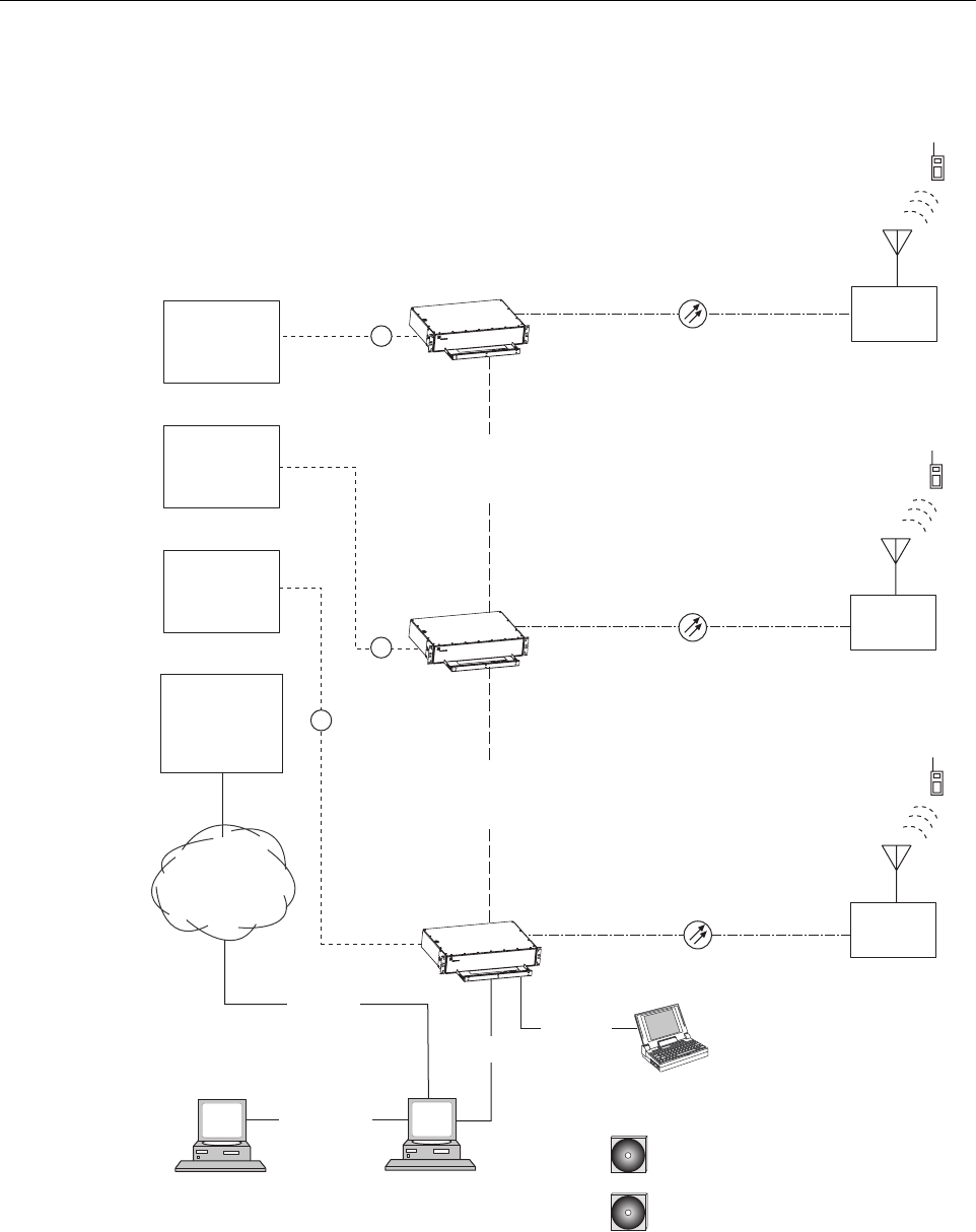
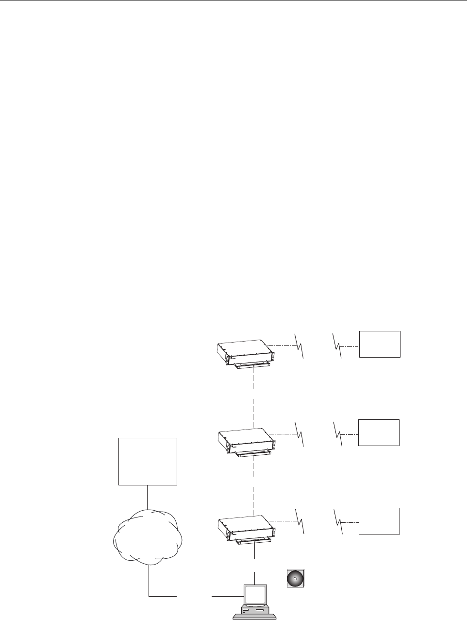
2.1 Basic SCS System Components
The basic components of a typical Digivance SCS system and their function are shown in
Figure 1-1. A basic SCS system consists of a Host Unit (HU) and a Remote Unit (RU). The HU
consists of a rack-mountable chassis that is designed for use in an indoor environment. The RU
consists of a sealed enclosure that is designed for use in an outdoor environment. Control and
monitoring functions are provided by the Digivance Element Management System (EMS).
ADCP-75-187 • Preliminary Issue 1B • November 2005 • Section 1: OVERVIEW
Page 1-2
© 2005, ADC Telecommunications, Inc.
Figure 1-1. SCS System Overview Diagram
HOST UNIT 1
HOST UNIT 2
HOST UNIT 3
NETWORK
OPERATIONS
CENTER
(REMOTE
INTERFACE)
CONTROLLER
AREA
NETWORK
20564-B
RF
RF
RF
CONTROLLER
AREA
NETWORK
REMOTE
UNIT 1
REMOTE
UNIT 3
REMOTE
UNIT 2
PC COMPUTER WITH EMS
AND SNMP PROXY AGENT
(PERMANENT CONNECTION)
RS-232
ASCII
RS-232
CD-ROM WITH EMS
SOFTWARE
NETWORK SNMP
MANAGER
CD-ROM WITH SNMP PROXY
AGENT SOFTWARE (OPTIONAL)
ETHERNET
LAN
PC COMPUTER WITH EMS
(TEMPORARY CONNECTION)
T1, DS0
WITH RS232
CONVERSION,
OR OTHER
MEDIUM
RS-232
ENHANCED
BASE
TRANSCEIVER
STATION 1
ENHANCED
BASE
TRANSCEIVER
STATION 2
ENHANCED
BASE
TRANSCEIVER
STATION 3
ADCP-75-187 • Preliminary Issue 1B • November 2005 • Section 1: OVERVIEW
Page 1-3
© 2005, ADC Telecommunications, Inc.
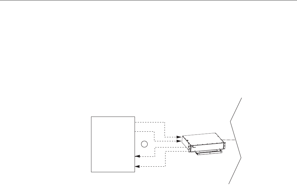
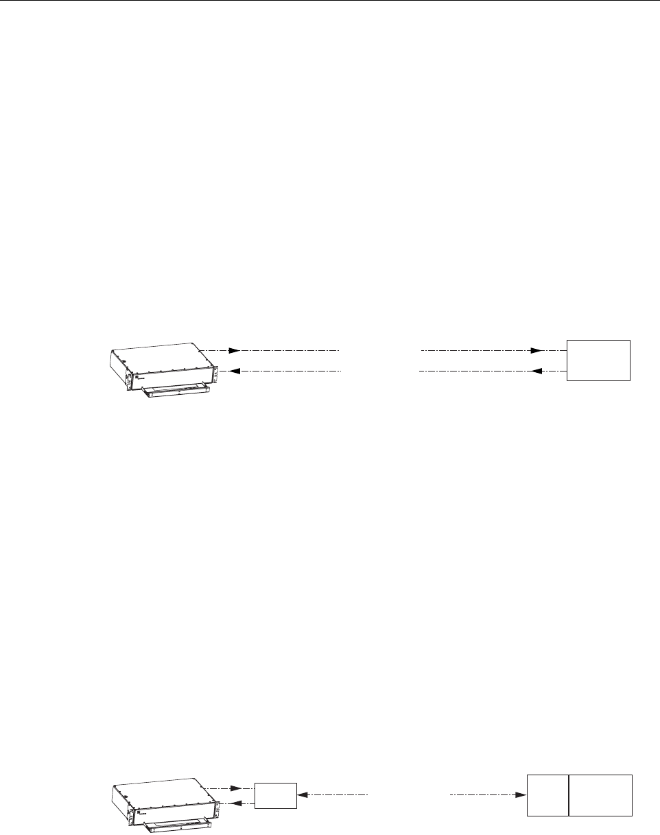
2.2 Enhanced Base Transceiver Station Interface
The HU is interfaced with an EBTS over coaxial cables as shown in Figure 1-2. The EBTS
provides the RF channel inputs and outputs for a designated sector. In the forward path, the HU
receives two RF inputs from the EBTS. The HU digitizes the RF spectrum and then converts it
to digital optical signals for transport to the RU. In the reverse path, the HU receives digital
optical signals from the RU. The HU converts the digital optical signals back to two RF outputs
which are supplied to the EBTS over the coaxial cable interface.
Figure 1-2. EBTS/HU Interface
2.3 Subscriber Unit Interface
The RU interfaces with the subscriber units (cell phones) through an antenna. In the reverse
path, the RU receives RF spectrum from each subscriber unit (see Figure 1-1). The RU digitizes
the RF spectrum and then converts it to digital optical signals for transport to the HU over the
optical fiber link. In the forward path, the RU receives digital optical signals from the HU. The
RU converts the optical signals to RF spectrum for transmission to the subscriber units. The RU
is connected to an antenna (not provided) which transmits and receives the subscriber unit RF
spectrum.
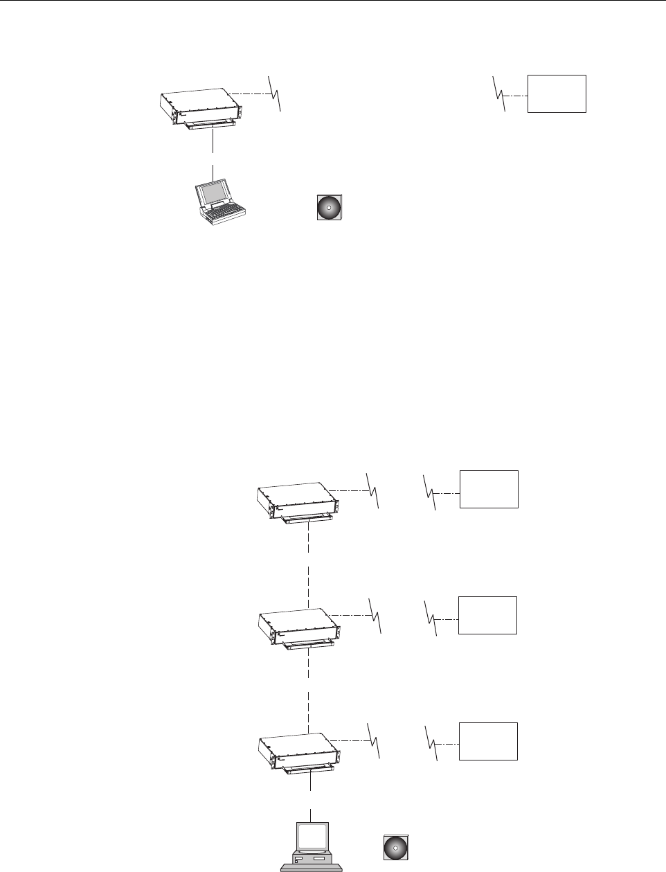
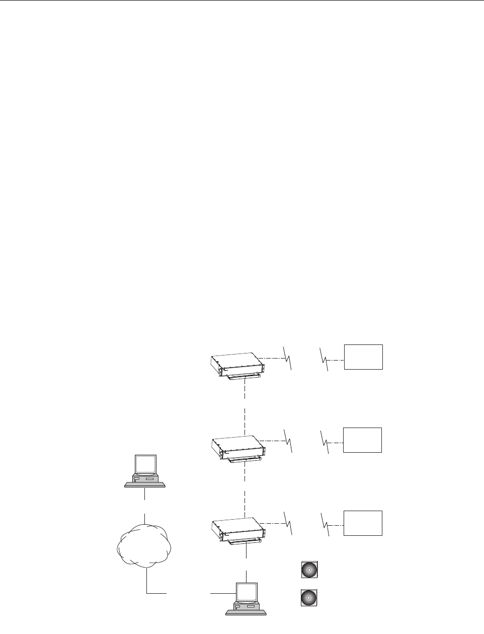
2.4 Local Management Interface
Communications with an individual Digivance system is supported through a local management
interface capability as shown in Figure 1-3. A local management interface requires a PC-type
computer loaded with the Digivance Element Management System (EMS) software. EMS
provides the various control and monitoring functions required to locally manage a Digivance
system. The EMS computer connects directly to the HU through the computer’s RS-232 port.
Operation is implemented through the EMS Graphical User Interface (GUI). The GUI consists
of a series of screens from which the user selects the desired option or function. An RS-232
service port is provided on both the HU for connecting the EMS computer.
20856-A
HOST UNIT
RF
ENHANCED
BASE
TRANSCEIVER
STATION
FORWARD
PATHS
REVERSE
PATHS
ADCP-75-187 • Preliminary Issue 1B • November 2005 • Section 1: OVERVIEW
Page 1-4
© 2005, ADC Telecommunications, Inc.
Figure 1-3. Local Management of a Single Digivance System
An EMS computer may be used to locally manage a networked group of multiple Digivance
systems as shown in Figure 1-4. A Controller Area Network (CAN) port is provided on each
HU. Up to twenty-four HU’s may be linked together through the CAN interface and controlled
by the same EMS computer. All the networked HU’s and the associated RU’s may be managed
by connecting the EMS computer to one HU. The EMS computer provides an RS-232 port (#1)
to support the interface with the networked HU’s.
Figure 1-4. Local Management of Networked Digivance Systems
HOST UNIT
LAPTOP WITH EMS
(LOCAL INTERFACE)
20565-A
CD-ROM WITH DIGIVANCE
ELEMENT MANAGEMENT
SYSTEM (EMS) SOFTWARE
REMOTE
UNIT
RS-232
PC COMPUTER WITH EMS
(LOCAL INTERFACE WITH
MULTIPLE SYSTEMS)
HOST UNIT
HOST UNIT
HOST UNIT
RS-232
20857-A
CD-ROM WITH DIGIVANCE
ELEMENT MANAGEMENT
SYSTEM (EMS) SOFTWARE
CAN
CAN
REMOTE
UNIT
REMOTE
UNIT
REMOTE
UNIT
NOTE: THE MAXIMUM LENGTH
FOR THE RS-232 CABLE IS 75 FEET
NOTE: THE SUM MAXIMUM
LENGTH FOR THE CAN BUS
CABLES IS 75 FEET
ADCP-75-187 • Preliminary Issue 1B • November 2005 • Section 1: OVERVIEW
Page 1-5
© 2005, ADC Telecommunications, Inc.
2.5 Network Operations Center Interface
Communications between a Network Operations Center (NOC) and a networked group of
multiple Digivance systems is supported by a NOC interface capability as shown in Figure 1-5.
To support the NOC interface, a PC-type computer loaded with the Digivance Element
Management System (EMS) software is required. EMS provides the various control and
monitoring functions required to remotely manage multiple Digivance systems through the
NOC interface.
A Controller Area Network (CAN) port is provided on each HU. Up to twenty-four HU’s may
be linked together through the CAN interface and controlled by the same EMS computer. All
the networked HU’s and the associated RU’s may be managed by connecting the EMS computer
to one HU. The EMS computer provides an RS-232 port (#1) to support the interface with the
networked HU’s.
The NOC can be linked to the EMS computer through a T1 system, DS0 with RS232
conversion, or some other medium. The EMS computer provides an RS-232 ASCII interface
port (#2) to support the interface with the NOC.
At the NOC, control and monitoring of the networked Digivance systems is implemented
through a Network Element Manager (NEM) interface which requires only a VT100 terminal/
emulator for operation. The NEM interface language consists of simple ASCII text strings. All
communications are input as either SET or GET commands which result in ASCII text string
responses from the specified system or systems.
Figure 1-5. Remote Management of Networked Digivance Systems Through NOC Interface
PC COMPUTER WITH
EMS SOFTWARE
HOST UNIT
HOST UNIT
HOST UNIT
RS-232
20858-A
CD-ROM WITH EMS
SOFTWARE
CAN
CAN
NETWORK
OPERATIONS
CENTER
(REMOTE
INTERFACE)
RS-232
ASCII
T1, DS0
WITH RS232
CONVERSION,
OR OTHER
MEDIUM
REMOTE
UNIT
REMOTE
UNIT
REMOTE
UNIT
ADCP-75-187 • Preliminary Issue 1B • November 2005 • Section 1: OVERVIEW
Page 1-6
© 2005, ADC Telecommunications, Inc.
2.6 SNMP Interface
Communications between an external Simple Network Management Protocol (SNMP) Manager
and a networked group of multiple Digivance systems is supported by an SNMP interface
capability as shown in Figure 1-6. To support the SNMP interface, a PC-type computer loaded
with both the Digivance Element Management System (EMS) software and the SNMP Proxy
Agent software is required. The EMS and SNMP Proxy Agent software plus the associated
Management Information Base (MIB) provide the various control (Set) monitoring (Get) and
trap functions required to remotely manage multiple Digivance systems using an SNMP
Manager.
A Controller Area Network (CAN) port is provided on each HU. Up to twenty-four HU’s may
be linked together through the CAN interface and controlled by the same EMS computer. All
the networked HU’s and the associated RU’s may be managed by connecting the EMS computer
to one HU. The EMS computer provides an RS-232 port (#1) to support the interface with the
networked HU’s.
The SNMP Manager may be linked with the EMS computer through a Local Area Network
(LAN). The EMS computer provides an Ethernet port to support the interface with the LAN.
The SNMP Proxy Agent supports two versions of the SNMP protocol: SNMPv1 and SNMPv2c.
A facility to Register/Unregister an SNMP Manager for receiving traps is also supported by the
SNMP Proxy Agent. The SNMP Manager is an option and must be ordered separately from
the EMS software.
Figure 1-6. Remote Management of Networked Digivance Systems Through SNMP Manager
PC COMPUTER WITH EMS
AND SNMP PROXY AGENT
HOST UNIT
HOST UNIT
HOST UNIT
RS-232
20859-A
CD-ROM WITH EMS
SOFTWARE
CD-ROM WITH SNMP
PROXY AGENT SOFTWARE
CAN
CAN
LOCAL
AREA
NETWORK
ETHERNET
NETWORK
SNMP
MANAGER
ETHERNET
REMOTE
UNIT
REMOTE
UNIT
REMOTE
UNIT
ADCP-75-187 • Preliminary Issue 1B • November 2005 • Section 1: OVERVIEW
Page 1-7
© 2005, ADC Telecommunications, Inc.
3 SYSTEM FUNCTIONS AND FEATURES
This section describes various system level functions and features of the Digivance system.
3.1 Fiber Optic Transport
In a typical Digivance LRCS system, the HU is connected to the RU over two single-mode
optical fibers. One fiber is used to transport the forward path optical signal. The other fiber is
used to transport the reverse path optical signal. Because the optical signal is digital, the input
and output RF signal levels at the HU or the RU are not dependent on the level of the optical
signal or the length of the optical fiber. A diagram of the fiber optic transport system for a
typical Digivance LRCS system is shown in Figure 1-7.
Figure 1-7. LRCS System Fiber Optic Transport - Typical
The maximum length of the optical links is dependent on the loss specifications of the optical
fiber, the losses imposed by the various connectors and splices, and the RF modulation protocol
response timing limitations. The basic system provides an optical budget of 25 dB (typical)
when used with 9/125 single-mode fiber.
In SCS applications, the forward path and reverse path optical signals from an HU/RU pair are
combined onto a single optical fiber. This is accomplished by using a passive bi-directional
Wavelength Division Multiplexer (WDM) system. The optical wavelengths used in the
Digivance system are 1550 nm for the forward path and 1310 nm for the reverse path. Because
different wavelengths are used for the forward and reverse paths, both signals can be combined
on a single optical fiber. A WDM module (accessory) is installed with the HU at the host site
The SCS RU, which is equipped with an internally mounted WDM, is installed at the remote
site as shown in Figure 1-8.
Figure 1-8. SCS System Fiber Optic Transport with Wavelength Division Multiplexer
HOST UNIT
18526-A
REMOTE
UNIT
FORWARD PATH
REVERSE PATH
FIBER OPTIC
LINK
20721-A
HOST UNIT
REMOTE
UNIT
FORWARD AND
REVERSE PATH
WDM WDM
FIBER OPTIC LINK

ADCP-75-187 • Preliminary Issue 1B • November 2005 • Section 1: OVERVIEW
Page 1-8
© 2005, ADC Telecommunications, Inc.
3.2 Control and Monitoring Software
The EMS software and the SNMP Proxy Agent software provide control and monitoring
functions for the Digivance system through the local, NOC, and SNMP interfaces. The EMS
software package supports the local and NOC interfaces but does not include the SNMP Proxy
Agent software which must be ordered separately. Both the EMS and the SNMP Proxy Agent
software are required to support the SNMP interface. All software files are provided on CD-
ROM’s. Software installation consists of copying the software files from the CD-ROM’s to a
designated directory on the hard-drive of the EMS computer.
The EMS software provides the capability to provision and configure the Digivance system for
operation. This includes selecting a site name, setting alarm thresholds, and setting forward and
reverse path RF gain adjustments. The EMS software also provides the capability to get alarm
messages (individual or summary), obtain data measurements, and to upgrade the HU/RU
system software. All control and monitor functions (except software upgrade which is not
supported by the NOC/NEM and SNMP interfaces and HU/RU pair site number assignment
which is not supported by the SNMP interface) may be implemented using the NOC/NEM
interface, the SNMP interface, or the EMS software GUI.
3.3 Fault Detection and Alarm Reporting
LED indicators are provided on the front panel of the HU and on the underside of the RU to
indicate if the system is normal or if a fault is detected. In addition, normally open and normally
closed alarm contacts (for both major and minor alarms) are provided at the HU for connection
to a customer-provided external alarm system. All alarms can also be accessed through the
NOC/NEM interface, SNMP manager, or the EMS software GUI.
3.4 Powering
The HU is powered by ±24 or ±48 VDC and must be hard-wired to a local DC power source
through a fuse panel. A screw-down terminal strip is provided on the rear side of the HU for the
power connections.
The RU is powered by 90 to 265 VAC (nominal 120 or 240 VAC), 47 to 63 Hz power. On an
optional basis, the RU may be powered by 60 to 89 VAC, 47 to 63 Hz power. A connector is
provided on the underside of the RU for the AC power connections. A 3-wire AC power cable
rated for outdoor use is included with the RU. The stub end of the cable must be hard-wired to
the AC power source.
3.5 Equipment Mounting and Location
The HU consists of a rack-mountable chassis assembly that is designed for mounting in a non-
condensing indoor environment such as inside a wiring closet or within an environmentally-
controlled cabinet. The HU is usually installed within 20 feet of the EBTS and may be mounted
in either a 19- or 23-inch, WECO or EIA, equipment rack.
The RU consists of a sealed aluminum enclosure designed for mounting in either an indoor or
outdoor environment. The RU may be mounted from a pole or the exterior side of a building
with the standard mounting bracket or from a strand with an accessory bracket.

ADCP-75-187 • Preliminary Issue 1B • November 2005 • Section 1: OVERVIEW
Page 1-9
© 2005, ADC Telecommunications, Inc.
4 DUAL-BAND REMOTE UNIT SCS SYSTEMS
Sections 1 through 3 described the functions and features of a typical SCS system equipped with
one HU and the single-band RU. Each single-band RU is equipped with the electronics to
support one frequency band. If it is necessary so support two frequency bands (such as 800/900
MHz SMR and 1900 MHz) at the same remote location, a dual-band RU can be deployed. A
dual-band RU provides the electronic and optical functionality of two single-band RU’s except
that all the electronic and optical components are housed within a single enclosure.
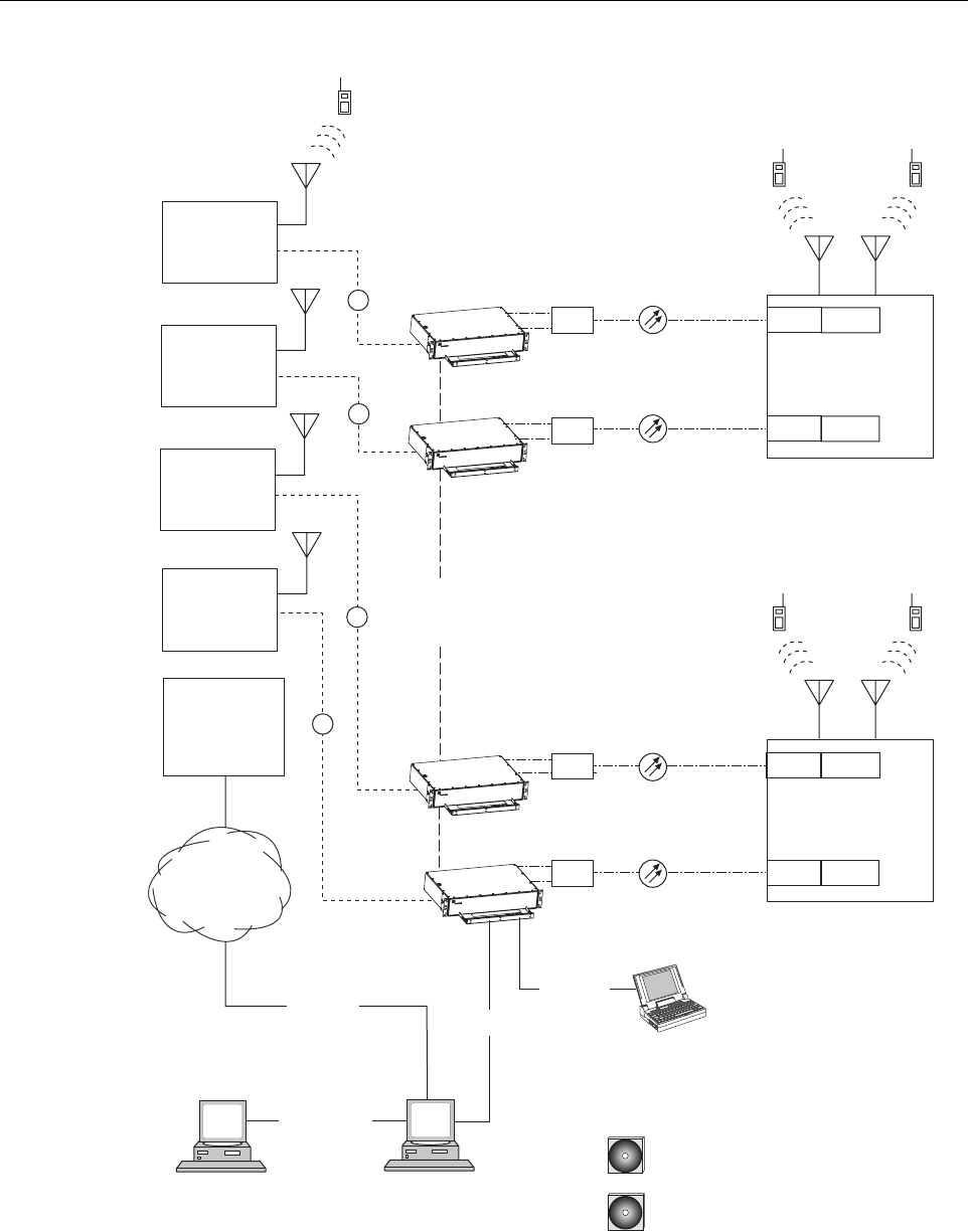
A dual-band SCS system consists of two standard host units and a dual-band RU that are linked
together over two optical fibers. At the hub site, each HU is connected to a separate EBTS
facility. The dual-band RU supports the frequency bands (such as 800/900 MHz SMR and 1900
MHz) associated with the two connected HU’s. Each HU and the corresponding RU electronics
function independently of each other and may be managed separately using the same element
manager system (EMS). Figure 1-9 shows a typical SCS system equipped with a dual-band RU.
One fiber is used to transport the forward/reverse path optical signals for one SCS system. The
other fiber is used to transport the forward/reverse path optical signals for the other SCS system.
ADCP-75-187 • Preliminary Issue 1B • November 2005 • Section 1: OVERVIEW
Page 1-10
© 2005, ADC Telecommunications, Inc.
Figure 1-9. SCS System With Dual-Band Remote Units Overview Diagram
PC COMPUTER WITH EMS
AND SNMP PROXY AGENT
(PERMANENT CONNECTION)
HOST UNIT 1
HOST UNIT 2
HOST UNIT A
HOST UNIT B
NETWORK
OPERATIONS
CENTER
PC COMPUTER WITH EMS
(TEMPORARY CONNECTION)
T1, DS0
WITH RS232
CONVERSION,
OR OTHER
MEDIUM
RS-232
ASCII RS-232
20628-A
CD-ROM WITH EMS
SOFTWARE
RF
RS-232
NETWORK SNMP
MANAGER
CD-ROM WITH SNMP PROXY
AGENT SOFTWARE
ETHERNET
LAN
DUAL-BAND
REMOTE UNIT
DUAL-BAND
REMOTE UNIT
CONTROLLER
AREA
NETWORK
BAND 1
800/900 MHZ SMR
BAND A
800/900 MHZ SMR
BAND 2
1900 MHZ
BAND B
1900 MHZ
BASE STATION
ANTENNA
ENHANCED
BASE
TRANSCEIVER
STATION 1
ENHANCED
BASE
TRANSCEIVER
STATION 2
ENHANCED
BASE
TRANSCEIVER
STATION B
ENHANCED
BASE
TRANSCEIVER
STATION A
RF
RF
RF
UNIT 1
UNIT 2
UNIT A
UNIT B
WDM
WDM
WDM
WDM
WDM
WDM
WDM
WDM

ADCP-75-187 • Preliminary Issue 1B • November 2005 • Section 2: DESCRIPTION
Page 2-1
© 2005, ADC Telecommunications, Inc.
SECTION 2: DESCRIPTION
1 INTRODUCTION. . . . . . . . . . . . . . . . . . . . . . . . . . . . . . . . . . . . . . . . . . . . . . . . . . . . . . . . . . . . . . . . . . . . . . . .2-2
2 HOST UNIT . . . . . . . . . . . . . . . . . . . . . . . . . . . . . . . . . . . . . . . . . . . . . . . . . . . . . . . . . . . . . . . . . . . . . . . . . . .2-2
2.1 Primary Components . . . . . . . . . . . . . . . . . . . . . . . . . . . . . . . . . . . . . . . . . . . . . . . . . . . . . . . . . . . . . .2-2
2.2 Mounting . . . . . . . . . . . . . . . . . . . . . . . . . . . . . . . . . . . . . . . . . . . . . . . . . . . . . . . . . . . . . . . . . . . . . .2-2
2.3 Fault Detection and Alarm Reporting . . . . . . . . . . . . . . . . . . . . . . . . . . . . . . . . . . . . . . . . . . . . . . . . . . .2-3
2.4 RF Signal Connections . . . . . . . . . . . . . . . . . . . . . . . . . . . . . . . . . . . . . . . . . . . . . . . . . . . . . . . . . . . . .2-4
2.5 RF Signal Level Adjustments. . . . . . . . . . . . . . . . . . . . . . . . . . . . . . . . . . . . . . . . . . . . . . . . . . . . . . . . .2-4
2.6 Propagation Delay . . . . . . . . . . . . . . . . . . . . . . . . . . . . . . . . . . . . . . . . . . . . . . . . . . . . . . . . . . . . . . . .2-4
2.7 Optical Connection . . . . . . . . . . . . . . . . . . . . . . . . . . . . . . . . . . . . . . . . . . . . . . . . . . . . . . . . . . . . . . .2-4
2.8 Controller Area Network Interface Connection . . . . . . . . . . . . . . . . . . . . . . . . . . . . . . . . . . . . . . . . . . . . .2-5
2.9 Service Interface Connection. . . . . . . . . . . . . . . . . . . . . . . . . . . . . . . . . . . . . . . . . . . . . . . . . . . . . . . . .2-5
2.10 Powering . . . . . . . . . . . . . . . . . . . . . . . . . . . . . . . . . . . . . . . . . . . . . . . . . . . . . . . . . . . . . . . . . . . . . .2-5
2.11 Cooling . . . . . . . . . . . . . . . . . . . . . . . . . . . . . . . . . . . . . . . . . . . . . . . . . . . . . . . . . . . . . . . . . . . . . . .2-5
2.12 User Interface . . . . . . . . . . . . . . . . . . . . . . . . . . . . . . . . . . . . . . . . . . . . . . . . . . . . . . . . . . . . . . . . . . .2-5
3 REMOTE UNIT. . . . . . . . . . . . . . . . . . . . . . . . . . . . . . . . . . . . . . . . . . . . . . . . . . . . . . . . . . . . . . . . . . . . . . . . .2-9
3.1 Primary Components . . . . . . . . . . . . . . . . . . . . . . . . . . . . . . . . . . . . . . . . . . . . . . . . . . . . . . . . . . . . . .2-9
3.2 Mounting . . . . . . . . . . . . . . . . . . . . . . . . . . . . . . . . . . . . . . . . . . . . . . . . . . . . . . . . . . . . . . . . . . . . . 2-10
3.3 Fault Detection and Alarm Reporting . . . . . . . . . . . . . . . . . . . . . . . . . . . . . . . . . . . . . . . . . . . . . . . . . . 2-10
3.4 Antenna Cable Connection . . . . . . . . . . . . . . . . . . . . . . . . . . . . . . . . . . . . . . . . . . . . . . . . . . . . . . . . . 2-11
3.5 RF Signal Level Adjustment . . . . . . . . . . . . . . . . . . . . . . . . . . . . . . . . . . . . . . . . . . . . . . . . . . . . . . . . 2-11
3.6 Optical Connection . . . . . . . . . . . . . . . . . . . . . . . . . . . . . . . . . . . . . . . . . . . . . . . . . . . . . . . . . . . . . . 2-11
3.7 Powering . . . . . . . . . . . . . . . . . . . . . . . . . . . . . . . . . . . . . . . . . . . . . . . . . . . . . . . . . . . . . . . . . . . . . 2-11
3.8 Cooling . . . . . . . . . . . . . . . . . . . . . . . . . . . . . . . . . . . . . . . . . . . . . . . . . . . . . . . . . . . . . . . . . . . . . . 2-11
3.9 User Interface . . . . . . . . . . . . . . . . . . . . . . . . . . . . . . . . . . . . . . . . . . . . . . . . . . . . . . . . . . . . . . . . . . 2-12
4 ACCESSORY ITEMS . . . . . . . . . . . . . . . . . . . . . . . . . . . . . . . . . . . . . . . . . . . . . . . . . . . . . . . . . . . . . . . . . . . . 2-14
4.1 Strand Mount Kit for RU . . . . . . . . . . . . . . . . . . . . . . . . . . . . . . . . . . . . . . . . . . . . . . . . . . . . . . . . . . . 2-14
4.2 Lightning Protector for RU . . . . . . . . . . . . . . . . . . . . . . . . . . . . . . . . . . . . . . . . . . . . . . . . . . . . . . . . . 2-14
4.3 Solar Shields . . . . . . . . . . . . . . . . . . . . . . . . . . . . . . . . . . . . . . . . . . . . . . . . . . . . . . . . . . . . . . . . . . 2-14
5 DIGIVANCE ELEMENT MANAGEMENT SYSTEM. . . . . . . . . . . . . . . . . . . . . . . . . . . . . . . . . . . . . . . . . . . . . . . . . . 2-14
5.1 Digivance EMS Primary Components . . . . . . . . . . . . . . . . . . . . . . . . . . . . . . . . . . . . . . . . . . . . . . . . . . 2-14
5.2 Software Installation . . . . . . . . . . . . . . . . . . . . . . . . . . . . . . . . . . . . . . . . . . . . . . . . . . . . . . . . . . . . . 2-16
5.3 Computer Operation. . . . . . . . . . . . . . . . . . . . . . . . . . . . . . . . . . . . . . . . . . . . . . . . . . . . . . . . . . . . . . 2-16
5.4 Digivance EMS Computer Interface Connections . . . . . . . . . . . . . . . . . . . . . . . . . . . . . . . . . . . . . . . . . . 2-16
5.5 Digivance Software User Interfaces . . . . . . . . . . . . . . . . . . . . . . . . . . . . . . . . . . . . . . . . . . . . . . . . . . . 2-17
6 SPECIFICATIONS . . . . . . . . . . . . . . . . . . . . . . . . . . . . . . . . . . . . . . . . . . . . . . . . . . . . . . . . . . . . . . . . . . . . . . 2-18
_________________________________________________________________________________________________________
Content Page

ADCP-75-187 • Preliminary Issue 1B • November 2005 • Section 2: DESCRIPTION
Page 2-2
© 2005, ADC Telecommunications, Inc.
1 INTRODUCTION
This section describes the basic components of a typical Digivance SCS system including the
Host Unit (HU), Remote Unit (RU), element management system, and accessories. The system
specifications are provided in a table at the end of this section.
2 HOST UNIT
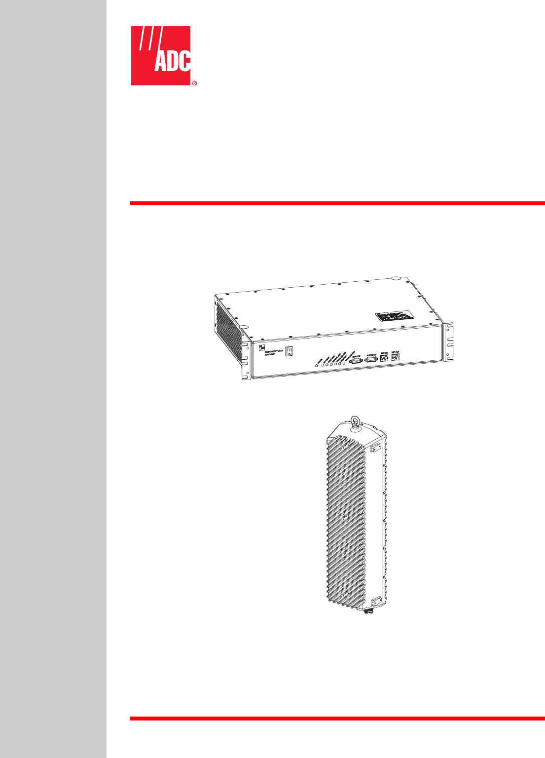
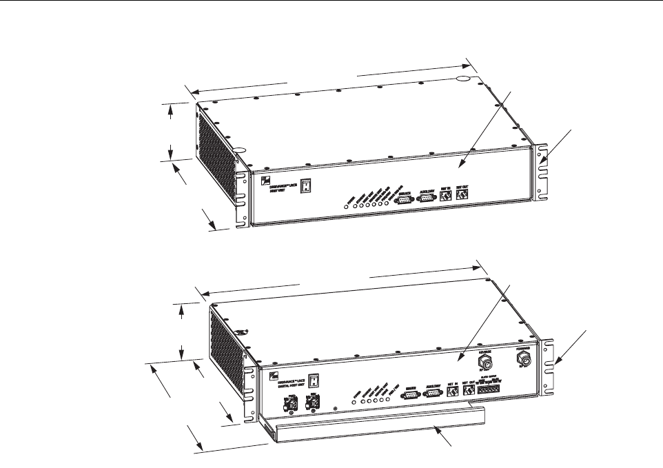
Two versions of the HU are available. The rear access HU, shown in Figure 2-1, is used with
800/900 MHz SMR systems. The front access HU, also shown in Figure 2-1, is used with 800
and 1900 MHz systems. Connection points for the RF, optical, and alarm cables are provided on
the rear side of the rear access HU and on the front side of the front access HU. Both HU
versions provide the following basic functions:
• Provides a limited adjustable RF interface with the BTS.
• Provides a fiber optic interface with the RU.
• Digitizes the two forward path composite RF signals.
• Converts the two digitized forward path RF signals to a digital optical signal.
• Converts the digitized reverse path optical signal to two digitized RF signals.
• Converts the two digitized reverse path RF signals to two composite RF signals.
• Sends alarm information to an external alarm system through relay contact closures
• Provides an RS-232 interface for connecting the EMS computer.
• Provides a CAN interface for networking multiple HUs.
2.1 Primary Components
The HU consists of an electronic circuit board assembly and a fan assembly that are mounted
within a powder-paint coated sheet metal enclosure. The enclosure provides a mounting point
for the circuit board and fan assemblies and controls RF emissions. The only user-replaceable
component is the fan assembly. The HU is designed for use within a non-condensing indoor
environment such as inside a wiring closet or cabinet. The front access HU is also equipped
with a front cable management tray and vertical cable guides.
2.2 Mounting
The HU is intended for rack-mount applications. A pair of reversible mounting brackets is
provided that allow the HU to be mounted in either a 19-inch or 23-inch EIA or WECO
equipment rack. When the rear access HU is installed, the front panel of the HU is flush with the
front of the rack. When the front access HU is installed, the front panel of the HU is flush with
the front of the rack and the cable management tray extends 3.9 inches (99 mm) beyond the
front panel. Screws are provided for securing the HU to the equipment rack.
ADCP-75-187 • Preliminary Issue 1B • November 2005 • Section 2: DESCRIPTION
Page 2-3
© 2005, ADC Telecommunications, Inc.
Figure 2-1. Rear and Front Access Host Units
2.3 Fault Detection and Alarm Reporting
The HU detects and reports various internal and external faults including host unit fault, optical
fault, power fault, temperature fault, and RF fault. Various front panel Light Emitting Diode
(LED) indicators turn from green to red or yellow if a fault is detected. A set of alarm contacts
(normally open and normally closed) are provided for reporting an alarm to an external alarm
system when a fault is detected. Both major alarm (system operation seriously affected) and
minor alarm (system operation not affected or only slightly degraded) contacts are provided.
Fault and alarm information may also be accessed locally through the EMS software GUI or
remotely through the NOC/NEM interface or SNMP interface. An alarm history file is
maintained by the EMS software so that a record is kept of all alarms as they occur. This is
useful when an alarm is reported and cleared before the reason for the alarm can be determined.
The status of the HU, the alarm state (major or minor), and other alarm information is
summarized and reported over the service interface, the CAN interface, and the optical interface
to the RU. In addition, the status of the RU is transmitted to the HU over the optical interface
and reported over the service interface and the CAN interface.
17.1 INCHES
(433 mm)
3.5 INCHES
(88 mm)
12.2 INCHES
(311 mm)
FRONT PANEL
MOUNTING
BRACKET
(BOTH SIDES)
REAR ACCESS HOST UNIT
FRONT ACCESS HOST UNIT
20666-A
17.2 INCHES
(437 mm)
3.5 INCHES
(89 mm)
11.4 INCHES
(290 mm)
15.3 INCHES
(389 mm)
FRONT PANEL
CABLE MANAGEMENT
TRAY
MOUNTING
BRACKET
(BOTH SIDES)

ADCP-75-187 • Preliminary Issue 1B • November 2005 • Section 2: DESCRIPTION
Page 2-4
© 2005, ADC Telecommunications, Inc.
2.4 RF Signal Connections
The RF signal connections between the rear access HU and the EBTS are supported through
four N-type female connectors. Two connectors are used for the forward path RF signals and
two connectors are used for the reverse path RF signals.
The RF signal connections between the front access HU and the EBTS are supported through
two N-type female connectors. One connector is used for the forward path RF signal and the
other connector is used for the reverse path RF signal.
In most installations, it is usually necessary to install external attenuators to support the RF
interface between the HU and the EBTS. The HU should be as close as possible to the EBTS to
minimize coaxial cable losses.
2.5 RF Signal Level Adjustments
The HU is equipped with several attenuators for adjusting the signal levels of the forward and
reverse path RF signals. The attenuators provide an attenuation adjustment range of 0 to 31 dB
and can be set in 1 dB increments. The attenuators are software controlled and are adjusted
through the EMS software GUI, NOC/NEM interface, or SNMP interface.
The host forward path attenuators adjust the level of the input RF signal(s) to the HU. Using
the forward path attenuator, an input signal with a nominal composite signal level of –9 dBm to
–40 dBm can be adjusted to produce maximum power output. Additional external attenuation
is required if the input signal level is greater than –9 dBm.
The host reverse path attenuators adjust the level of the output RF signal(s) from the HU and
will add from –1 dB of gain (attenuator set to 31 dB) to +30 dB of gain (attenuator set to 0 dB)
to the RF output signal(s) at the HU.
2.6 Propagation Delay
The HU forward and reverse path propagation delays may be adjusted in 0.1 µsec increments
within a range of 0 to 63 µs. The propagation delay is software controlled and may be adjusted
through the EMS software GUI, NOC/NEM interface, or SNMP interface.
2.7 Optical Connection
Optical connections between the HU and the RU are supported through two optical ports
equipped with UPC/SC (flat) connectors. One port is used for the forward path optical signal
connection and the other port is used for the reverse path optical signal connection.
Note: The optimum composite RF input signal level for 800/900 MHz SMR systems is
–20 dBm.

ADCP-75-187 • Preliminary Issue 1B • November 2005 • Section 2: DESCRIPTION
Page 2-5
© 2005, ADC Telecommunications, Inc.
2.8 Controller Area Network Interface Connection
Controller Area Network (CAN) interface connections between multiple HUs are supported by
a pair of RJ-45 jacks. One of the jacks is designated as the network IN port and the other jack is
designated as the network OUT port. The CAN interface allows up to 24 HUs to be connected
together (in daisy-chain fashion) and controlled through a single EMS computer.
2.9 Service Interface Connection
The service interface connection between the HU and the EMS computer is supported by a
single DB-9 female connector. The service connector provides an RS-232 DTE interface. When
multiple HUs are networked together, the supporting EMS computer may be connected to the
service connector of any one of the networked HUs.
2.10 Powering
The HU is powered by ± 21 to ± 60 VDC power (nominal ± 24 or ± 48 VDC). The power is fed to
the HU through a screw-down type terminal strip located on the rear side of the unit. Power to
the HU must be supplied through a fuse panel such as the PowerWorx GMT Series Fuse Panel
(available separately). The power circuit for each HU must be protected with a 3 Amp GMT
fuse. An On/Off switch is provided on the HU front panel.
2.11 Cooling
Continuous airflow for cooling is provided by dual fans mounted on the right side of the HU
housing. A minimum of 3 inches (76 mm) of clearance space must be provided on both the left
and right sides of the HU for air intake and exhaust. An alarm is generated if a high temperature
condition (>50º C/122º F) occurs. The fans may be field-replaced if either fan fails.
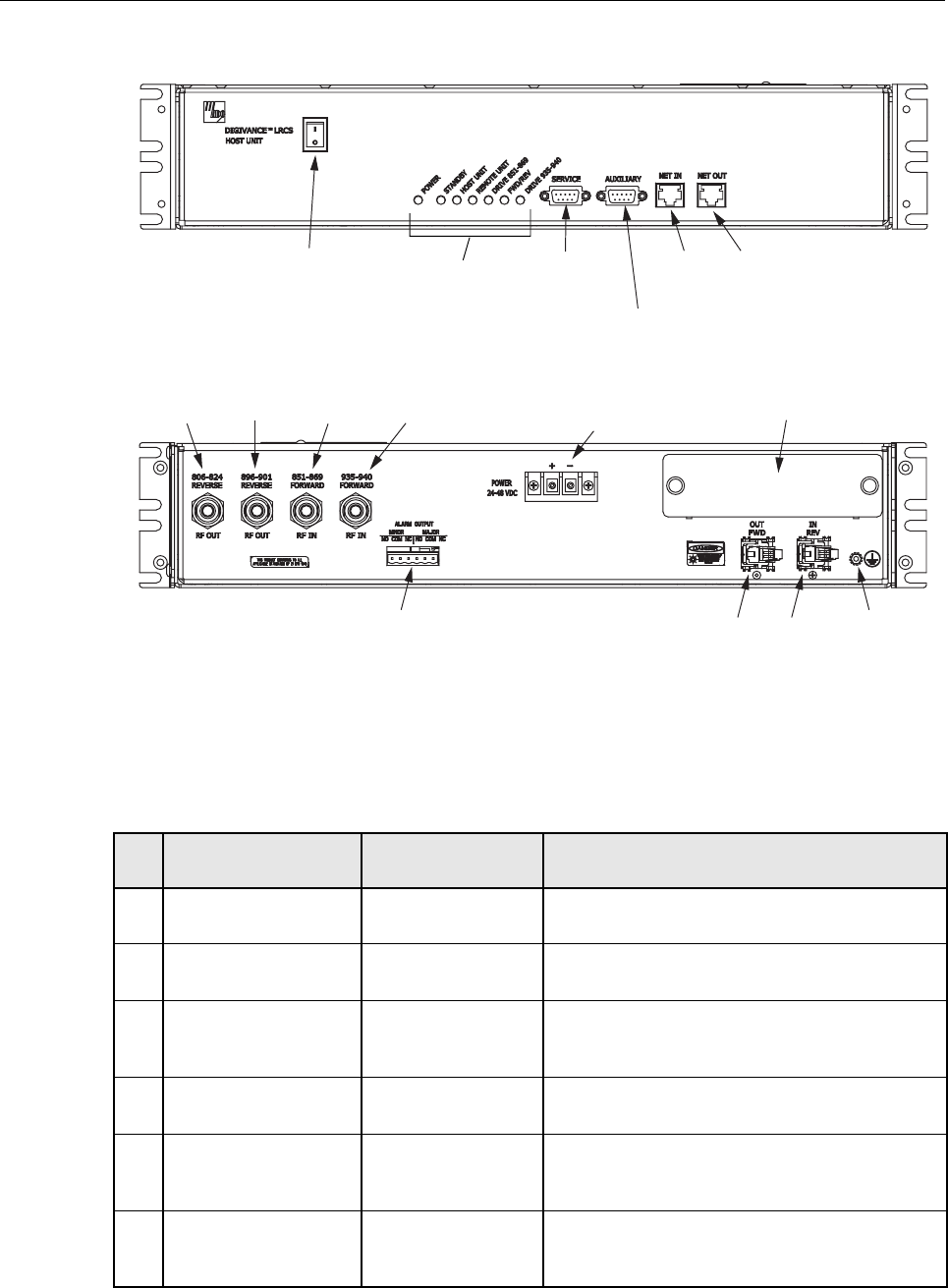
2.12 User Interface
The HU user interface consists of the various connectors, switches, terminals, and LEDs that are
provided on the HU front and rear panels. The rear access HU user interface points are
indicated in Figure 2-2 and described in Table 2-1. The front access HU user interface points
are indicated in Figure 2-3 and described in Table 2-2.
ADCP-75-187 • Preliminary Issue 1B • November 2005 • Section 2: DESCRIPTION
Page 2-6
© 2005, ADC Telecommunications, Inc.
Figure 2-2. Rear Access Host Unit User Interface
Table 2-1. Host Unit User Interface
REF
NO
USER INTERFACE
DESIGNATION DEVICE FUNCTIONAL
DESCRIPTION
1 I/0 On/Off rocker
switch
Provides DC power on/off control.
2 POWER Multi-colored LED
(green/yellow)
Indicates if the HU is powered (green) or unpow-
ered (off). See Note.
3 STANDBY Multi-colored LED
(green/yellow/red)
Indicates if the system is in the Normal (off),
Standby (blinking green), Test (blinking red), or
Program Load (blinking yellow) state. See Note.
4 HOST UNIT Multi-colored LED
(green/yellow/red)
Indicates if the HU is normal (green), overheated
(yellow), or faulty (red). See Note.
5 REMOTE UNIT Multi-colored LED
(green/yellow/red)
Indicates if no alarms (green), a minor alarm
(yellow), or a major alarm (red) is reported by the
RU. See Note.
6 DRIVE 851–869 Multi-colored LED
(green/yellow/red)
Indicates if the level of the 851–869 MHz RF
input signal to the HU is normal (green), low
(yellow), or high (red). See Note.
(1) DC POWER
ON/OFF SWITCH
(21)
REV
(20)
FWD
(REFERENCE
ITEMS 2 - 8)
LED INDICATORS
(9) SERVICE
INTERFACE
CONNECTOR
(11) NET IN
CONNECTOR
(10) AUXILIARY
CONNECTOR
(12) NET OUT
CONNECTOR
(19) ALARM
OUTPUT CONNECTOR
(13) 806-824
REVERSE
(15) 851-869
FORWARD
(16) 935-940
FORWARD
(14) 896-901
REVERSE
20021-A
(17) DC POWER
TERMINAL STRIP
REAR VIEW
FRONT VIEW
(18) COVER PLATE
(22)
GROUNDING
STUD

ADCP-75-187 • Preliminary Issue 1B • November 2005 • Section 2: DESCRIPTION
Page 2-7
© 2005, ADC Telecommunications, Inc.
7FWD/REV
(PORT 1/PORT 2)
Multi-colored LED
(green/red)
Indicates if the reverse/forward path optical sig-
nals from the RU/HU are normal (green), if no
signals are detected (red), or if excessive errors
are detected (red). See Note.
8 DRIVE 935–940 Multi-colored LED
(green/yellow/red)
Indicates if the level of the 935–940 MHz RF
input signal to the HU is normal (green), low
(yellow), or high (red). See Note.
9 SERVICE DB-9 connector
(female)
Connection point for the RS-232 service inter-
face cable.
10 AUXILIARY DB-9 connector
(female)
Connection point for the RS-232 auxiliary inter-
face cable. Not supported by SCS Remote Unit.
11 NET IN RJ-45 jack (female) Connection point for the CAN interface input
cable.
12 NET OUT RJ-45 jack (female) Connection point for the CAN interface output
cable.
13 806–824 REVERSE N-type female RF
coaxial connector
Output connection point for the 806–824 MHz
reverse path RF coaxial cable.
14 896–901 REVERSE N-type female RF
coaxial connector
Output connection point for the 896–901 MHz
reverse path RF coaxial cable.
15 851–869 FORWARD N-type female RF
coaxial connector
Input connection point for the 851–869 MHz for-
ward path RF coaxial cable.
16 935–940 FORWARD N-type female RF
coaxial connector
Input connection point for the 935–940 MHz for-
ward path RF coaxial cable.
17 POWER 24–48 VDC Screw-type terminal
strip
Connection point for the DC power wiring.
18 No designation Cover plate Covers the mounting slot for the wavelength divi-
sion multiplexer module.
19 ALARM OUTPUT Screw-type terminal
connector (14–26
AWG)
Connection point for an external alarm system.
Includes normally open (NO), normally closed
(NC), and common (COM) wiring connections.
20 FWD (PORT 1) UPC/SC connector
(flat single-mode)
Output connection point for the forward path
optical fiber.
21 REV (PORT 2) UPC/SC connector
(flat single-mode)
Input connection point for the reverse path opti-
cal fiber.
22 Chassis ground stud Connection point for a chassis grounding wire.
Note: A more detailed description of LED operation is provided in Section 4.
Table 2-1. Host Unit User Interface, continued
REF
NO
USER INTERFACE
DESIGNATION DEVICE FUNCTIONAL
DESCRIPTION

ADCP-75-187 • Preliminary Issue 1B • November 2005 • Section 2: DESCRIPTION
Page 2-8
© 2005, ADC Telecommunications, Inc.
Figure 2-3. Front Access Host Unit User Interface
Table 2-2. Host Unit User Interface
REF
NO
USER INTERFACE
DESIGNATION DEVICE FUNCTIONAL
DESCRIPTION
1I/0 On/Off rocker switch Provides DC power on/off control.
2 FWD SC connector
(single-mode)
Output connection point for the forward path
optical fiber.
3 REV SC connector
(single-mode)
Input connection point for the reverse path pri-
mary optical fiber.
4 POWER Multi-colored LED
(green/yellow)
Indicates if the HU is powered (green) or unpow-
ered (off). See Note.
5 STANDBY Multi-colored LED
(green/yellow/red)
Indicates if the system is in the Normal (off),
Standby (blinking green), Test (blinking red), or
Program Load (blinking yellow) state. See Note.
6 HOST UNIT Multi-colored LED
(green/yellow/red)
Indicates if the HU is normal (green), overheated
(yellow), or faulty (red). See Note.
7 REMOTE UNIT Multi-colored LED
(green/yellow/red)
Indicates if no alarms (green), a minor alarm
(yellow), or a major alarm (red) is reported by the
RU. See Note.
8 DRIVE Multi-colored LED
(green/yellow/red)
Indicates if the level of the RF input signal to the
HU is normal (green), low (yellow), or high
(red). See Note.
9 FWD/REV Multi-colored LED
(green/red)
Indicates if the reverse path optical signals from
the STM are normal (green), if no signals are
detected (red), or if excessive errors are detected
(red). See Note.
10 SERVICE DB-9 connector
(female)
Connection point for the RS-232 service inter-
face cable.
11 AUXILIARY DB-9 connector
(female)
Not used with SCS systems.
(1) DC POWER
ON/OFF SWITCH
NOTE: SHOWN WITHOUT
CABLE MANAGEMENT TRAY
(2) PORT 1
OR FWD
CONNECTOR
(3) PORT 2
OR REV
CONNECTOR
(REFERENCE
ITEMS 4 - 9)
LED INDICATORS
(10) SERVICE
INTERFACE
CONNECTOR
(12) NET IN
CONNECTOR
(13) NET OUT
CONNECTOR
(14) ALARM
OUTPUT
CONNECTOR
(15) REVERSE
RF OUT
(16) FORWARD
RF IN
20667-A
(11) AUXILIARY INTERFACE
CONNECTOR
(NOT USED FOR SCS)

ADCP-75-187 • Preliminary Issue 1B • November 2005 • Section 2: DESCRIPTION
Page 2-9
© 2005, ADC Telecommunications, Inc.
3 REMOTE UNIT
The RU is available in either a single-band or a dual-band version. Both versions of the RU
provide the following basic functions:
• Convert the digitized forward path optical signals to digitized RF signals.
• Convert the digitized forward path RF signals to composite RF signals.
• Digitize the reverse path composite RF signals.
• Convert the digitized reverse path RF signals to digitized optical signals.
• Provide an RF interface (antenna port) for the remote antenna(s).
• Provide an optical interface for the HU.
• Transport alarm, control, and monitoring information to the HU via the optical interface.
• Accept AC power input.
• Provide a visual indication of unit status
3.1 Primary Components
Depending on the version, the RU consists of either two or four electronic assemblies mounted
within an environmentally-sealed cast-aluminum enclosure. The Spectrum Transport Module
(STM) provides optical-to-RF and RF-to-optical conversion and digitizing functions; alarm,
control, and monitoring functions; power conversion functions; and RF filtering and interface
functions. The Linear Power Amplifier (LPA) works in conjunction with the STM to amplify
12 NET IN RJ-45 jack (female) Connection point for the CAN interface input
cable.
13 NET OUT RJ-45 jack (female) Connection point for the CAN interface output
cable.
14 ALARM OUTPUT Screw-type terminal
connector (14–26
AWG)
Connection point for an external alarm system.
Includes normally open (NO), normally closed
(NC), and common (COM) wiring connections.
15 REV RF OUT N-type female RF
coaxial connector
Output connection point for the primary reverse
path RF coaxial cable.
16 FWD RF IN N-type female RF
coaxial connector
Input connection point for the forward path RF
coaxial cable.
POWER 24–48 VDC
(Rear side - not shown)
Screw-type terminal
strip
Connection point for the DC power wiring.
(Rear side - not shown)
Chassis ground stud Connection point for a chassis grounding wire.
Note: A more detailed description of LED operation is provided in Section 4.
Table 2-2. Host Unit User Interface, continued
REF
NO
USER INTERFACE
DESIGNATION DEVICE FUNCTIONAL
DESCRIPTION
ADCP-75-187 • Preliminary Issue 1B • November 2005 • Section 2: DESCRIPTION
Page 2-10
© 2005, ADC Telecommunications, Inc.
the forward path RF signal. The aluminum enclosure provides a mounting point for the
electronic assemblies, controls RF emissions, seals out dirt and moisture, and provides passive
cooling. The electronic assemblies are not user replaceable or accessible. All connectors and
indicators are mounted on the bottom of the RU enclosure for easy access.
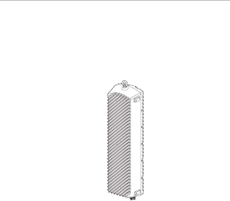
The single-band version of the RU consists of one STM and one LPA mounted within the same
enclosure. The dual-band version, shown in Figure 2-4, consists of two STM’s and two LPA’s
mounted within the same enclosure. The dual-band version makes it possible to support two
separate frequency bands with a single RU.
Figure 2-4. Dual-Band Remote Unit
3.2 Mounting
The RU may be mounted on a flat vertical surface (such as the side of a building) or on a utility
pole. A combination wall/pole mounting bracket is provided with each unit. A separate strand-
mount kit (accessory item) is available if it is necessary to mount the RU from a cable. A
grounding lug is provided on the bottom of the RU enclosure for connecting a grounding wire.
3.3 Fault Detection and Alarm Reporting
The RU detects and reports various faults including remote unit fault, optical fault, output power
fault, temperature fault, and power amplifier fault. A single bottom-mounted Light Emitting
Diode (LED) indicator turns from off to red if a major fault is detected. The status of the STM
and LPA, the alarm state, and other fault information is summarized and reported over the
optical interface to the HU. Fault and alarm information may be accessed at the HU through the
EMS software GUI or remotely through the NOC/NEM interface or SNMP interface.
20568-C

ADCP-75-187 • Preliminary Issue 1B • November 2005 • Section 2: DESCRIPTION
Page 2-11
© 2005, ADC Telecommunications, Inc.
3.4 Antenna Cable Connection
The antenna cable connection between the RU and the antenna is supported through a single N-
type female connector. The N-type connector provides a connection point for the antenna cable.
The forward and reverse path RF signals are combined on the same antenna cable. It is
recommended that a lightning protector (accessory item) be connected to the antenna port prior
to connecting the antenna cable. On an optional basis, the dual-band RU may be equipped with
two N-type connectors to support antenna connections to two separate antennas.
3.5 RF Signal Level Adjustment
The RU is equipped with digital attenuators for adjusting the signal level of the forward path RF
output signals. The remote forward path attenuators adjust the level of the two output RF
signals at the RU antenna port and will add from 0 to 31 dB of attenuation to the output signal
level. The attenuator can be set in 1 dB increments. The attenuator is software controlled and is
adjusted through the EMS software GUI, the NOC/NEM interface, or SNMP interface.
3.6 Optical Connection
Fiber optic connections between the single-band RU and the associated HU are supported
through one OptiTap hardened optical connector port. All single-band RU’s are equipped with
an internally mounted Wavelength Division Multiplexer (WDM). This allows a single optical
port to provide the optical fiber connection for the combined forward and reverse path signals.
Fiber optic connections between the dual-band RU and the two associated HU’s (two HU’s are
required with a dual-band RU) are supported through two OptiTap hardened optical connector
ports. All dual-band RU’s are equipped with two internally-mounted WDM’s. One port
provides the optical fiber connection for the combined forward and reverse path signals for HU
#1. The other port provides the optical fiber connection for the combined forward and reverse
path signals for HU #2.
An APC/SC (angled) connector and adapter is mounted within each OptiTap optical port. Drop
cables terminated with OptiTap connectors are available separately. The stub end of each drop
cable must be routed to an external splice enclosure (not provided) for splicing to the Outside
Plant (OSP) fiber optic cable.
3.7 Powering
The RU is powered by 90 to 265 VAC (nominal 120 or 240 VAC), 47 to 63 Hz power. On an
optional basis, the RU may be powered by 60 to 89 VAC, 47 to 63 Hz power. The power is
supplied through a three-wire AC power cable that is provided with the RU. The power cable
connects to a mini 3-pin power connector mounted on the bottom of the RU enclosure. The stub
end of the cable must be hard-wired to the AC power source. The cable is UL and National
Electrical Code (NEC) approved for continuous outdoor exposure without conduit.
3.8 Cooling
Passive cooling of the electronic assemblies is provided by conducting excess heat from the
electronic components to the aluminum enclosure. The heat is dissipated to the outside air by
radiation and convection air flow over the enclosure’s external cooling fins. An alarm is
generated if a high temperature condition occurs within the enclosure. If necessary, the RU may
be equipped with solar shields (accessory) that reduce the effect of solar loading on the
aluminum enclosure.
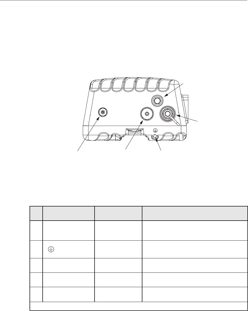
ADCP-75-187 • Preliminary Issue 1B • November 2005 • Section 2: DESCRIPTION
Page 2-12
© 2005, ADC Telecommunications, Inc.
3.9 User Interface
The RU user interface consists of the connectors, grounding lug, and LED that are provided on
the bottom of the RU enclosure. The user interface points for the single-band RU are indicated
in Figure 2-5 and described in Table 2-3. The user interface points for the interim single-band
and the dual-band RU are indicated in Figure 2-6 and described in Table 2-4.
Figure 2-5. Single-Band Remote Unit User Interface
Table 2-3. Single-Band Remote Unit User Interface
REF
NO
USER INTERFACE
DESIGNATION DEVICE FUNCTIONAL
DESCRIPTION
1 BAND 1 OptiTap APC/SC
connector (angled
single-mode)
Input/output connection point for the combined
forward and reverse path optical fiber. The host
unit must be equipped with a WDM.
2 Threaded hole with
hex socket screw
Connection point for the grounding wire.
3 POWER Mini 3-wire AC
power connector
Connection point for the AC power cord.
4 ANT N-type female RF
coaxial connector
Connection point for the antenna cable.
5 No designation Red LED
(off/red)
Indicates if the RU is powered and normal (off)
or if a major fault is detected (red). See Note.
Note: A more detailed description of the LED operation is provided in Section 4.
(1) OPTICAL PORT
(2) GROUNDING LUG
CONNECTION POINT
(4) N-TYPE CONNECTOR
FOR ANTENNA
(5) LED
INDICATOR
(3) AC POWER
CONNECTOR 20981-A
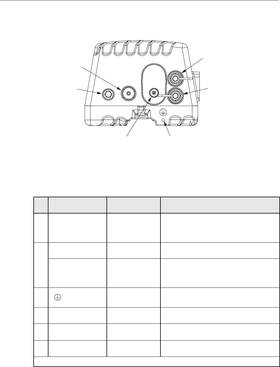
ADCP-75-187 • Preliminary Issue 1B • November 2005 • Section 2: DESCRIPTION
Page 2-13
© 2005, ADC Telecommunications, Inc.
Figure 2-6. Interim Single-Band and Dual-Band Remote Unit User Interface
Table 2-4. Interim Single-Band and Dual-Band Remote Unit User Interface
REF
NO
USER INTERFACE
DESIGNATION DEVICE FUNCTIONAL
DESCRIPTION
1 BAND 1 OptiTap APC/SC
connector (angled
single-mode)
Input/output connection point for the BAND 1
(see tag to identify system) combined forward
and reverse path optical fiber. The host unit must
be equipped with a WDM.
2 BAND 2 (Interim
single band unit)
Unused OptiTap
connector
Band 2 optical port not used with the interim sin-
gle-band version of the RU.
BAND 2 (Dual-band
unit)
OptiTap APC/SC
connector (angled
single-mode)
Input/output connection point for the BAND 2
(see tag to identify system) combined forward
and reverse path optical fiber. The host unit must
be equipped with a WDM.
3 Threaded hole with
hex socket screw
Connection point for the grounding wire.
4 ANT N-type female RF
coaxial connector
Connection point for the antenna cable.
5 No designation Red LED
(off/red)
Indicates if the RU is powered and normal (off)
or if a major fault is detected (red). See Note.
6 POWER Mini 3-wire AC
power connector
Connection point for the AC power cord.
Note: A more detailed description of the LED operation is provided in Section 4.
20976-A
(1) BAND 1 OPTICAL PORT
(USED WITH INTERIM SINGLE-
BAND AND DUAL-BAND UNIT)
(2) BAND 2 OPTICAL PORT
(NOT USED WITH INTERIM
SINGLE-BAND UNIT)
(3) GROUNDING LUG
CONNECTION POINT
(4) N-TYPE CONNECTOR
FOR ANTENNA
(5) LED
INDICATOR
(6) AC POWER
CONNECTOR

ADCP-75-187 • Preliminary Issue 1B • November 2005 • Section 2: DESCRIPTION
Page 2-14
© 2005, ADC Telecommunications, Inc.
4 ACCESSORY ITEMS
This section provides a brief description of the accessory items that are available separately for
the SCS system. The accessory items may or may not be required depending on the application.
4.1 Strand Mount Kit for RU
A strand-mount kit is available if the application requires that the RU be mounted from an
overhead cable system. Mounting pads are provided on the side of the RU enclosure for
securing a pair of cable-attachment clips. Screws are used to secure the cable-attachment clips
to the RU enclosure.
4.2 Lightning Protector for RU
An external lightning protector is available separately for the RU. It is recommended that an
external lightning protector be installed at the RU antenna port to reduce the chance of damage
to electronic components should a lightning strike occur. The antenna terminal on the lighting
protector may be equipped with either an N-type female connector or a 7/16 mm DIN female
connector depending on the application requirements.
4.3 Solar Shields
A solar shield kit is available if the RU must be mounted in full sunlight for extended periods of
time with extremely high ambient temperatures. The solar shields attach to the exterior of the
RU enclosure and shade the enclosure from direct exposure to the sun. The solar shields are
constructed of sheet metal and are painted to match the color of the RU enclosure. All fasteners
and brackets required for installation are provided with the kit.
5 DIGIVANCE ELEMENT MANAGEMENT SYSTEM
The Digivance Element Management System (EMS) is a software-based network management
tool that provides control and monitoring functions for the Digivance system. The Digivance
EMS is used to provision and configure new systems for operation, set system operating
parameters, get system alarm and status messages, and upgrade the system software. The EMS
supports local control by an on-site service technician and also remote control through either a
Network Operations Center (NOC) interface or an SNMP interface.
5.1 Digivance EMS Primary Components
The primary components of the Digivance EMS, shown in Figure 2-7, are packaged separately
from the various Digivance hardware items and consist of the following items: User Manuals,
mouse pad, license agreement, and either one or two CD-ROM’s which contain the various
elements of the software. The software installs on a PC-type computer which is not provided. A
cable (DGVL-000000CBPC) for connecting the EMS computer to the HU is available
separately as an accessory item.
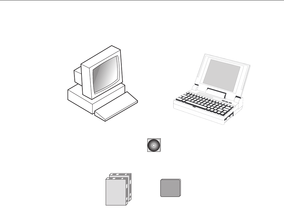
ADCP-75-187 • Preliminary Issue 1B • November 2005 • Section 2: DESCRIPTION
Page 2-15
© 2005, ADC Telecommunications, Inc.
Figure 2-7. Digivance Element Management System
EMS Software: The EMS software and the Java 2 Version 1.3.1 Runtime Environment
software are loaded on a CD-ROM. The EMS software provides local monitor and control
functions through a Graphical User Interface (GUI) and remote monitor and control functions
through the NOC/NEM interface.
SNMP Proxy Agent Software: The SNMP Proxy Agent software (when included) is loaded on
a CD-ROM. The SNMP Proxy Agent together with the EMS provides for remote monitor and
control functions through a network SNMP manager. When the SNMP interface is required for
system operation, both the EMS software and SNMP Proxy Agent software must be installed on
the same computer. The SNMP Proxy Agent software will not function without the EMS
software.
Control Programs: The host and remote control programs are installed by the factory in each
respective host unit or RU. Updated versions of the host and remote control program software
will be provided by Customer Service on a “as needed” basis.
EMS AND SNMP AGENT
CD-ROM(S)
OR
NOTE: COMPUTER NOT PROVIDED
18705-C
USER MANUALS
MOUSE PAD

ADCP-75-187 • Preliminary Issue 1B • November 2005 • Section 2: DESCRIPTION
Page 2-16
© 2005, ADC Telecommunications, Inc.
5.2 Software Installation
Software installation consists of inserting each specified CD-ROM into the computer’s CD-
ROM drive and then running the software install programs. This places the EMS, Java 2
Runtime Environment, and SNMP Proxy Agent (if included) software files in assigned folders
on the computer’s hard drive. Software installation instructions are provided in the Digivance
Element Management System User Manual (See Related Publications section).
5.3 Computer Operation
Permanent control and monitoring functions may be provided by a PC-type desk-top computer
that is permanently connected to a HU. The EMS program must be running in order for the
NOC interface to function. Both the EMS program and SNMP Proxy Agent program must be
running in order for the SNMP interface to function. A PC-type lap-top computer running just
the EMS program can be used as a portable network management tool for service and
maintenance purposes. The laptop computer may be connected temporarily to the HU to
trouble-shoot problems on-site and then removed when the maintenance task is completed. The
specifications for the EMS computer are provided in the Digivance Element Management
System User Manual (See Related Publications section).
5.4 Digivance EMS Computer Interface Connections
The service interface connection between the EMS computer and the HU requires that the EMS
computer be equipped with a DB-9 connector that is configured to provide an RS-232 DCE
interface. A straight-through RS-232 interface cable (accessory item) equipped with a male DB-
9 connector on one end and a PC-compatible connector on the other end is required to link the
EMS computer to the HU.
The NOC interface connection between the EMS computer and the NOC requires that the EMS
computer be equipped with a connector that is configured to provide an RS-232 ASCII
interface. The link between the EMS computer and the NOC would generally be supported by a
T1 system, DS0 with RS232 conversion, or other medium. Cables and equipment (not provided)
to support the RS-232 interface connection between the EMS computer and the NOC interface
are required.
The SNMP interface connection between the EMS computer and the SNMP manager requires
that the EMS computer be equipped with an Ethernet port. The link between the EMS computer
and a network SNMP manager would generally be supported by a Local Area Network (LAN).
Cables and equipment (not provided) to support the connection between the EMS computer and
the LAN are required.
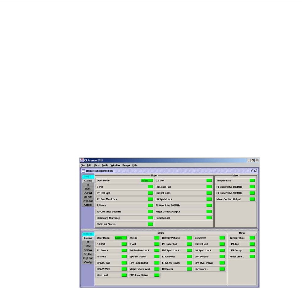
ADCP-75-187 • Preliminary Issue 1B • November 2005 • Section 2: DESCRIPTION
Page 2-17
© 2005, ADC Telecommunications, Inc.
5.5 Digivance Software User Interfaces
The Digivance EMS provides three software user interfaces: the EMS Graphical User Interface
(GUI), the Network Operation Center–Network Element Manager (NOC/NEM) interface, and
the SNMP interface. The EMS GUI, the NOC interface, and the SNMP interface provide the
same basic functions. However, the NOC interface and the SNMP interface cannot be used to
download new system software to the Digivance system. In addition, the SNMP interface
cannot be used to assign a system site number to a HU/RU pair during installation.
The EMS GUI is used for local control and monitoring operations. The EMS GUI consists of a
series of displays and screens, such as the one shown in Figure 2-8, that provide the user with
alarm and status information and that allow the user to set various operating parameters.
Directives are implemented by pointing and clicking on the desired action and also by entering
text in various dialog boxes. Refer to the Digivance Element Management System User Manual
(see Related Publications section) for additional information.
Figure 2-8. Typical EMS Graphical User Interface – Host/Remote Alarms Display
The NOC/NEM interface is a text-based command line interface that is used for remote control
and monitoring operations (except software download). The NOC/NEM interface consists of
defined ASCII text strings that are input as SET or GET commands followed by the action or
information required. A text string response is received from the specified Digivance system or
systems to confirm the requested action or to report the requested information. Examples of
several typical NOC-NEM interface commands and the responses received are shown in
Figure 2-9. The NOC/NEM interface requires only a VT100 terminal/emulator or a PC-type
computer that is loaded with a communication software such as Procomm Plus. While primarily
intended for use at the NOC, the NOC/NEM interface commands may also be input locally
from the EMS computer. Refer to the Digivance Element Management System User Manual
(see Related Publications section) for additional information.
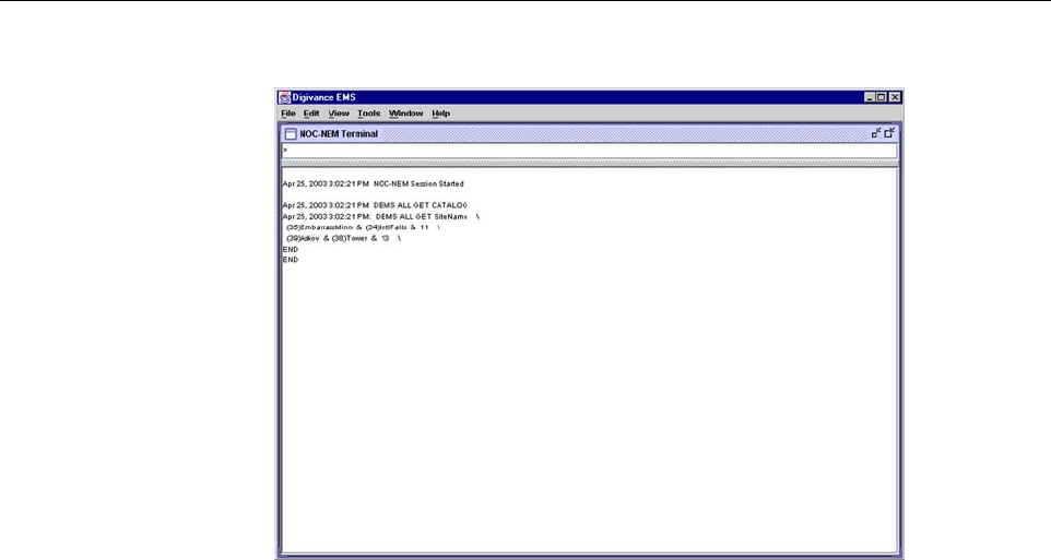
ADCP-75-187 • Preliminary Issue 1B • November 2005 • Section 2: DESCRIPTION
Page 2-18
© 2005, ADC Telecommunications, Inc.
Figure 2-9. NOC/NEM Interface Typical Commands
The SNMP interface is used for remote control and monitoring operations (except software
download and site number assignment). The SNMP interface uses a Management
Information Base (MIB) to define a list of identifiers that are supported by the SNMP agent.
The SNMP manager communicates with the SNMP agent over a LAN. Directives, based on the
MIB identifier, are issued by the SNMP manager to the SNMP agent along with instructions to
either get the specified identifier or set the specified identifier. The directive is then executed on
the Digivance system by the SNMP agent. The SNMP agent also has the ability to send
autonomous messages (called traps) to the SNMP manager to report changes in the status of the
managed system. The SNMP manager Stargazer Version 8.0 is available from ADC for use with
the LRCS SNMP agent. Other SNMP managers are available from various network
management software venders. Refer to the SNMP Agent Software User Manual (see Related
Publications section) for additional information.
6 SPECIFICATIONS
Refer to the following tables for the system, host unit, and remote unit specifications. All
specifications apply after a five minute warm-up period.
Table 2-5 – SCS 800/900 MHz SMR system nominal specifications
Table 2-6 – SCS 800 MHz system nominal specifications
Table 2-7 – SCS 1900 MHz system nominal specifications
Table 2-8 – Host Unit nominal specifications
Table 2-9 – WDM nominal specifications
Table 2-10 – Remote Unit nominal specifications

ADCP-75-187 • Preliminary Issue 1B • November 2005 • Section 2: DESCRIPTION
Page 2-19
© 2005, ADC Telecommunications, Inc.
Table 2-5. SCS 800/900 MHz SMR System Nominal Specifications
PARAMETER SPECIFICATION REMARKS
Optical - Host and Remote Unit
Fiber type 9/125, single-mode
Number of fibers required 1 for single-band remote unit
2 for dual-band RU
All SCS remote units include a
WDM.
Forward path wavelength 1550 nm
Reverse path wavelength 1310 nm
Optical transmit power output
Host Unit
Remote Unit
0 dBm
+1.3 dBm (includes WDM inser-
tion loss)
Optical budget 25 dB For optical BER of 10–6
Optical Receiver Input Maximum –15 dBm
Optical connectors UPC/SC Host unit
OptiTap APC/SC Remote unit
RF Forward Path - 800/900 MHz
System bandwidth 18 MHz
5 MHz
800 MHz transmit
900 MHz transmit
Frequency range 851–869 MHz
935–940 MHz
Gain of forward path
(Host input to Remote primary
antenna port)
77.5 dB At band center, room tempera-
ture, and 0 dB attenuation set-
ting. Includes power amplifier.
Gain flatness
Band flatness
Channel flatness
± 2.0 dB across freq. range
± 1.5 dB variation across any
1.25 MHz channel
Gain variation ± 3 dB over temp and unit-to-
unit
Propagation delay < 6 µs (typical) Excludes fiber delay
Configurable propagation delay
Range
Step size
0 to 63 µs
0.1µs ± 100 ns
Plus standard propagation delay
Spurious
In-band self generated
Dynamic range (noise floor)
<–13 dBm at remote output
<–60 dBc at 30 KHz bandwidth
Transmit peak-to-average >10 dB
Two-tone Intermodulation <–55 dBc two tones @ 5 Watts each
Nominal composite RF input
signal level
–40 dBm at 0 dB attenuation
–9 dBm at max. attenuation
–20 dBm is the optimal RF input
signal level.
Configurable input level
Range
Step size
31 dB
1 ± 0.5 dB ±10% of attenuation
monotonic

ADCP-75-187 • Preliminary Issue 1B • November 2005 • Section 2: DESCRIPTION
Page 2-20
© 2005, ADC Telecommunications, Inc.
Note 1: Per Industry Canada Section 5.3 - The rated output power of this equipment is for single
carrier operation. For situations where multiple carrier signals are present, the rating would have
to be reduced by 3.5 dB, especially where the output signal is re-radiated and can cause
interference to adjacent band users. This power reduction is to be by means of input power or
gain reduction and not by an attenuator at the output of the device.
Composite RF Output power of
both bands (see Note 1at end of
table)
38.1 dBm (6.5 Watts) at remote
antenna port with –40 dBm input
10 Watts at LPA output
Configurable RF Output
Range
Step size
31 dB at remote unit
1 ± 0.5 dB ± 10% of attenuation
monotonic
Transmit path insertion loss 2.5 dB maximum
RF Reverse Path - 800/900 MHz
System bandwidth 18 MHz
5 MHz
800 MHz receive
900 MHz receive
Frequency range 806–824 MHz
896–901 MHz
Propagation delay < 8 µs (typical) Excludes fiber delay
Configurable propagation delay
Range
Step size
Up to 63 µs
0.1µs ±1 100 ns
Plus standard propagation delay
Gain of reverse path
Overall gain
Gain variation
30 ± 2 dB at band center at room
temperature
3 dB over temperature
Gain flatness
Band flatness
Channel flatness
± 2.0 dB across frequency range
± 1.5 dB variation across any
1.25 MHz channel
Out-of-band rejection –40 dB bandwidth at < 30 MHz
Spurious (in-band self gener-
ated)
–110 dBm referred to input
Intermodulation –62 dBc two tones @ –50 dBm
System noise figure 9 dB at mid-band
Configurable RF output
Range
Step size
31 dB
1 ± 0.5 dB ± 10% of attenuation
monotonic
Blocking dynamic range 70 dB
Level limiting ALC threshold –40 dBm ± 3 dB instantaneous
Level limiting ALC range 27 dB
Table 2-5. SCS 800/900 MHz SMR System Nominal Specifications, continued
PARAMETER SPECIFICATION REMARKS

ADCP-75-187 • Preliminary Issue 1B • November 2005 • Section 2: DESCRIPTION
Page 2-21
© 2005, ADC Telecommunications, Inc.
Table 2-6. SCS 800 MHz System Nominal Specifications
PARAMETER SPECIFICATION REMARKS
Optical - Host and Remote Unit
Fiber type 9/125, single-mode
Number of fibers required 1 for single-band remote unit
2 for dual-band RU
All SCS remote units include a
WDM.
Forward path wavelength 1550 nm
Reverse path wavelength 1310 nm
Optical transmit power output
Host Unit
Remote Unit
0 dBm
+1.3 dBm (includes WDM inser-
tion loss)
Optical budget 25 dB For optical BER of 10–6
Optical Receive Input Maximum –15 dBm
Optical connectors UPC/SC Host unit
OptiTap APC/SC Remote unit
RF Forward Path - 800 MHz
System bandwidth
A band
B band
11 and 1.5 MHz
10 and 2.5 MHz
Frequency range
A band
B band
869–880 and 890–891.5 MHz
880–890 and 891.5–894 MHz
Out-of-band emissions
Primary –13 dBm per 1 MHz bandwidth
from 10 kHz to 20 GHz
Gain of forward path
(Host input to Remote primary
antenna port)
78.1 dB At band center, room tempera-
ture, and 0 dB attenuation set-
ting. Includes power amplifier.
Gain flatness
Band flatness
Channel flatness
± 2.0 dB across freq. range
± 1 dB variation across any 1.25
MHz channel
Gain variation ± 3 dB over temp and unit-to-
unit
Out-of-band rejection –40 dB at > ±17.5 MHz from
center of subband
Propagation delay < 6 µs (typical) Excludes fiber delay
Configurable propagation delay
Range
Step size
Up to 63 µs
0.1µs ± 100 ns
Plus standard propagation delay
Spurious
In-band self generated
Free dynamic range
<–13 dBm at remote output
<–60 dBc at 30 kHz bandwidth
Transmit peak-to-average >10 dB

ADCP-75-187 • Preliminary Issue 1B • November 2005 • Section 2: DESCRIPTION
Page 2-22
© 2005, ADC Telecommunications, Inc.
Two-tone Intermodulation <–55 dBc at remote output Two tones @ 5 Watts each
CDMA Intermodulation
885 kHz to 1.25 MHz
1.25 to 1.98 MHz
1.98 to 2.25 MHz
–45 dBc per 30 kHz
–8 dBm per 30 kHz
–55 dBc per 30 kHz
Absolute level
Nominal composite RF input
signal level
–40 dBm at 0 dB attenuation
–9 dBm at max. attenuation
An input signal level of –40 dBm
provides maximum output power
Configurable input level
Range
Step size
31 dB
1 ± 0.5 dB ±10% of attenuation
monotonic
Composite RF Output power
(see Note 1at end of table)
38.1 dBm (6.5 Watts) at remote
antenna port with –40 dBm input
10 Watts at LPA output
Configurable RF Output
Range
Step size
31 dB at remote unit
1 ±0.5 dB ±10% of attenuation
monotonic
Transmit path insertion loss 2.5 dB maximum
RF Reverse Path - 800 MHz
System bandwidth
A band
B band
11 and 1.5 MHz
10 and 2.5 MHz
Frequency range
A band
B band
824–835 and 845–846.5 MHz
835–845 and 846.5–849 MHz
Propagation delay 6 µs Excludes fiber delay
Configurable propagation delay
Range
Step size
Up to 63 µs
0.1µs ±1 100 ns
Plus standard propagation delay
Gain flatness
Band flatness
Channel flatness
1.5 dB across frequency range
±1 dB variation across any 1.25
MHz channel
Gain of reverse path
Overall gain
Gain variation
30 ± 2 dB at band center at room
temperature
3 dB over temperature
ALC not invoked
ALC not invoked
Out-of-band rejection –40 dB at > ±17.5 MHz from
center of subband
ALC not invoked
Spurious (in-band self gener-
ated)
–110 dBm referred to input ALC not invoked
Intermodulation –62 dBc two tones at –50 dBm
System noise figure 8 dB at mid-band ALC not invoked
Table 2-6. SCS 800 MHz System Nominal Specifications, continued
PARAMETER SPECIFICATION REMARKS