ADC Telecommunications DSR0805A Digivance WBDR Base Station User Manual EMSUser
ADC Telecommunications Inc Digivance WBDR Base Station EMSUser
UserManual.wiki
>
ADC Telecommunications
>
DSR0805A User Manual
>
wbdr part 9
Contents
1.
wbdr part 1
2.
wbdr part 2
3.
wbdr part 3
4.
wbdr part 4
5.
wbdr part 5
6.
wbdr part 6
7.
wbdr part 7
8.
wbdr part 8
9.
wbdr part 9
10.
Installation manual
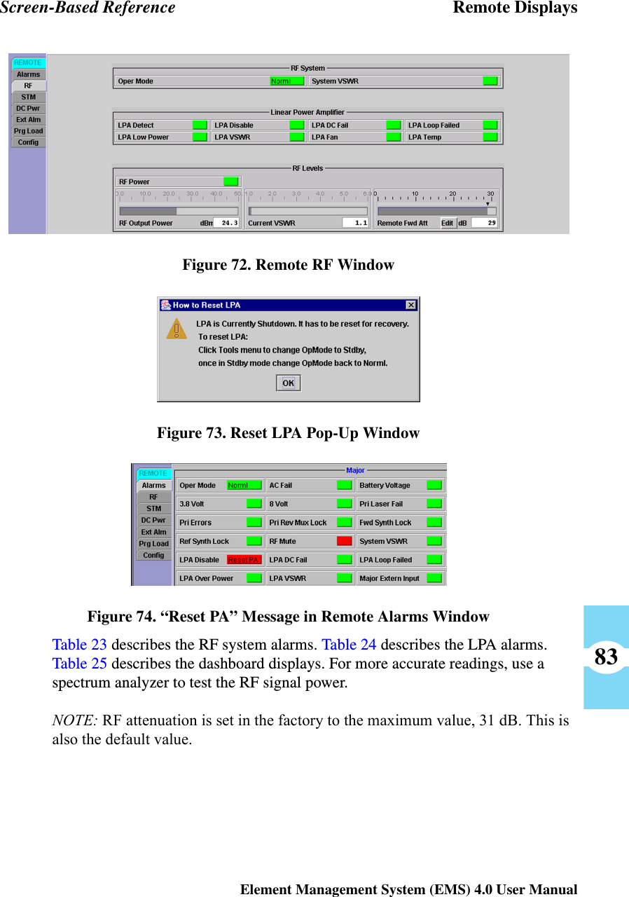
wbdr part 9
Navigation menu
Upload a User Manual
Namespaces
Wiki Guide
HTML
PDF
Info
Views
User Manual
Discussion / Help
Navigation