ADC Telecommunications DVICS800-1 Digivance 800 MHz Indoor Coverage Solution User Manual manual
ADC Telecommunications Inc Digivance 800 MHz Indoor Coverage Solution manual
manual
ADCP-75-110
Issue B
March 2001
Digivance™
800 Mhz Indoor Coverage Solution
Installation and Operation Manual
DRAFT
1126955 Rev A

ADCP-75-110 • Issue B • March 2001
Page ii
COPYRIGHT
2001, ADC Telecommunications, Inc.
All Rights Reserved
Printed in the U.S.A.
REVISION HISTORY
ISSUE DATE REASON FOR CHANGE
Issue B 03/01 Original
TRADEMARK INFORMATION
ADC and FiberGuide are registered trademarks of ADC Telecommunications, Inc.
Digivance is a trademark of ADC Telecommunications, Inc.
LC is a trademark of Lucent Technologies Inc.
TORX is a registered trademark of Textron, Inc.
DISCLAIMER OF LIABILITY
Contents herein are current as of the date of publication. ADC reserves the right to change the contents without prior notice.In no
event shall ADC be liable for any damages resulting from loss of data, loss of use, or loss of profits and ADC further
disclaims any and all liability for indirect, incidental, special, consequential or other similar damages. This disclaimer of
liability applies to all products, publications and services during and after the warranty period.
This publication may be verified at any time by contacting ADC’s Technical Assistance Center at 1-800-366-3891, extension
63475 (in U.S.A. or Canada) or 952-946-3475 (outside U.S.A. and Canada), or by e-mail to bcg_tac@adc.com.
ADC Telecommunications, Inc.
P.O. Box 1101, Minneapolis, Minnesota 55440-1101
In U.S.A. and Canada: 1-800-366-3891
Outside U.S.A. and Canada: (952) 938-8080
Fax: (952) 946-3292

ADCP-75-110 • Issue B • March 2001
Page iii
2001, ADC Telecommunications, Inc.
TABLE OF CONTENTS
Content Page
1 SYSTEM FUNCTIONAL OVERVIEW AND UNIT DESCRIPTIONS ........................................ 1
1.1 System Functional Overview ....................................................... 1
1.2 Digital Host Unit Description ....................................................... 3
1.3 Digital Remote Unit Description ..................................................... 7
1.4 Digital Expansion Unit Description ................................................... 9
1.5 Terms and Definitions............................................................12
1.6 Specifications .................................................................13
2 INSTALLATION PLANNING AND SYSTEM DESIGN................................................16
2.1 Base Station Interface Requirements ..................................................16
2.2 Locating and Mounting Requirements .................................................18
2.3 Powering Requirements ..........................................................19
2.4 Optical Options and Requirements ...................................................20
2.5 Coaxial Cable Requirements .......................................................20
2.6 System Expansion Planning ........................................................20
2.7 DRU Antenna Options ............................................................21
2.8 Local Alarm System Reporting Requirements ............................................21
2.9 Maintenance Requirements ........................................................22
2.10 System Design Recommendations ...................................................22
3 DIGITAL HOST UNIT INSTALLATION PROCEDURE................................................25
3.1 System Plan Review and Pre-Installation Cable Routing .....................................25
3.2 Tools and Materials .............................................................25
3.3 Unpacking and Inspection .........................................................25
3.4 Mounting Procecure ............................................................25
3.5 Chassis Ground Procedure.........................................................29
3.6 Coaxial Cable Connections ........................................................29
3.7 Ports 1-6 Optical Connections ......................................................30
3.8 DC Power Connections ...........................................................32
3.9 Local Alarm System Connections ....................................................33
3.10 AC Power Connections ...........................................................35
3.11 Create As-Built Drawing ..........................................................36
4 SYSTEM OPERATION ..................................................................37
4.1 Tools and Materials .............................................................37
4.2 Turn-Up System and Verify Operation .................................................37
4.3 Correct Installation Problems .......................................................39
4.4 Test System Performance .........................................................42
5 SYSTEM MAINTENANCE PROCEDURES ......................................................43
5.1 Tools and Materials .............................................................43
5.2 Fault Detection and Alarm Reporting ..................................................43
5.3 Fault Isolation and Troubleshooting ..................................................44
5.4 Test Procedures................................................................46
5.5 DHU or DEU Fan Replacement ......................................................49
Continued

ADCP-75-110 • Issue B • March 2001
Page iv
2001, ADC Telecommunications, Inc.
TABLE OF CONTENTS
Content Page
6 GENERAL INFORMATION ............................................................... 51
6.1 Warranty/Software ............................................................. 51
6.2 Software Service Agreement ....................................................... 51
6.3 Repair/Exchange Policy .......................................................... 51
6.4 Repair Charges................................................................ 51
6.5 Replacement/Spare Products ...................................................... 52
6.6 Returned Material .............................................................. 52
6.7 Customer Information and Assistance ................................................. 52

ADCP-75-110 • Issue B • March 2001
Page v
2001, ADC Telecommunications, Inc.
ABOUT THIS GUIDE
This installation and operation manual provides the following information:
• An overview of the Digivance Indoor Coverage Solution (ICS) and adescription of the
basic system components including the Digital Host Unit (DHU), Digital Expansion Unit
(DEU), and the Digital Remote Unit (DRU).
• System requirements for planning the Digivance ICS installation.
• Procedures for installing the DHU.
• Procedures for operating and maintaining the Digivance ICS.
• Product warranty, repair, return, and replacement information
The procedures for installing the DEU and DRU are provided in other publications which are
referenced in the Related Publications section and at appropriate points within this manual.
RELATED PUBLICATIONS
Listed below are related manuals and their publication numbers. Copies of these publications
can be ordered by contacting the ADC Technical Assistance Center at 1-800-366-3891
(in U.S.A. or Canada) or 952-946-3000, extension 3223 (outside U.S.A. and Canada).
Title/Description ADCP Number
Digivance ICS Digital Expansion Unit Installation Instructions ADCP-75-111
Provides a description of the DEU and procedures for installing the DEU.
Digivance ICS Digital Remote Unit Installation Instructions ADCP-75-112
Provides a description of the DRU and procedures for installing the DRU.
Digivance ICS Local Interface Unit User Manual ADCP-75-113
Provides a description of the LIU and procedures for installing the LIU.
Digivance ICS Remote Interface Unit User Manual ADCP-75-114
Provides adescription of the RIU and procedures for installing the RIU.

ADCP-75-110 • Issue B • March 2001
Page vi
2001, ADC Telecommunications, Inc.
ADMONISHMENTS
Important safety admonishments are used throughout this manual to warn of possible hazards
to persons or equipment. An admonishment identifies apossible hazard and then explains
what may happen if the hazard is not avoided. The admonishments —in the form of Dangers,
Warnings, and Cautions —must be followed at all times. These warnings are flagged by use
of the triangular alert icon (seen below), and are listed in descending order of severity of injury
or damage and likelihood of occurrence.
Danger:Danger is used to indicate the presence of a hazard that will cause severe personal
injury, death, or substantial property damage if the hazard is not avoided.
Warning:Warning is used to indicate the presence of a hazard that can cause severe
personal injury, death, or substantial property damage if the hazard is not avoided.
Caution:Caution is used to indicate the presence of a hazard that will or can cause minor
personal injury or property damage if the hazard is not avoided.
GENERAL SAFETY PRECAUTIONS
The following general admonishments apply throughout the procedures in this manual.
Warning:Wet conditions increase the potential for receiving an electrical shock when
installing or using electrically-powered equipment. To prevent electrical shock, never install
or use electrical equipment in a wet location or during a lightning storm.
Warning:The DRU is powered by 48 VDC power which is supplied over customer-provided
wiring. To prevent electrical shock when installing or modifying the DRU power wiring,
disconnect the wiring at the power source before working with uninsulated wires or terminals.
Danger:This equipment uses aClass 1Laser according to FDA/DCRH rules. Laser radiation
can seriously damage the retina of the eye. Do not look into the ends of any optical fiber. Do
not look directly into the optical adapters of any digital unit or exposure to laser radiation
may result. An optical power meter should be used to verify active fibers. Aprotective cap or
hood MUST be immediately placed over any radiating adapter or optical fiber connector to
avoid the potential of dangerous amounts of radiation exposure. This practice also prevents
dirt particles from entering the adapter or connector
Danger:Do not look into the ends of any optical fiber. Exposure to laser radiation may result. Do
not assume laser power is turned-off or the fiber is disconnected at the other end.

ADCP-75-110 • Issue B • March 2001
Page vii
2001, ADC Telecommunications, Inc.
Danger:Always allow sufficient fiber length to permit routing without severe bends. Fibers
may be permanently damaged if bent/curved to aradius of less than 1.5 inches (38 mm).
STANDARDS CERTIFICATION
FCC:This equipment complies with the applicable sections of Title 47 CFR Parts 15, 22, 24, and
90.
UL/CUL:This equipment complies with UL and CUL 1950 Standard for Safety for
Information Technology Equipment, Including Electrical Business Equipment.
FDA/CDRH:This equipment uses aClass 1LASER according to FDA/CDRH Rules. This
product conforms to all applicable standards of 21 CFR Part 1040.
LIST OF ACRONYMS AND ABBREVIATIONS
The acronyms and abbreviations used in this manual are detailed in the following list:
AAmperes
AC Alternating Current
AGC Automatic Gain Control
AMPS Advanced Mobile Phone Service
CDMA Code Division Multiple Access
CDRH Center for Devices and Radiological Health
CUL Canadian Underwriters Laboratories
DAS Distributed Antenna System
DC Direct Current
DEU Digital Expansion Unit
DHU Digital Host Unit
DRU Digital Remote Unit
EIA Electronic Industries Association
ERP Effective Radiated Power
ESD Electrostatic Discharge
FCC Federal Communications Commission
FDA Food and Drug Administration
ICS Indoor Coverage Solution
LIU Local Interface Unit
NOC Network Operations Center
PWR Power
RIU Remote Interface Unit
RF Radio Frequency

ADCP-75-110 • Issue B • March 2001
Page viii
2001, ADC Telecommunications, Inc.
RSSI Received Signal Strength Indication
RX Receive or Receiver
TDMA Time Division Multiple Access
TX Transmit or Transmitter
UL Underwriters Laboratories
UPS Uninterruptible Power Supply
VVolts
VAC Volts Alternating Current
VDC Volts Direct Current
WECO Western Electric Company

ADCP-75-110 • Issue B • March 2001
Page 1
© 2001, ADC Telecommunications, Inc.
1 SYSTEM FUNCTIONAL OVERVIEW AND UNIT DESCRIPTION
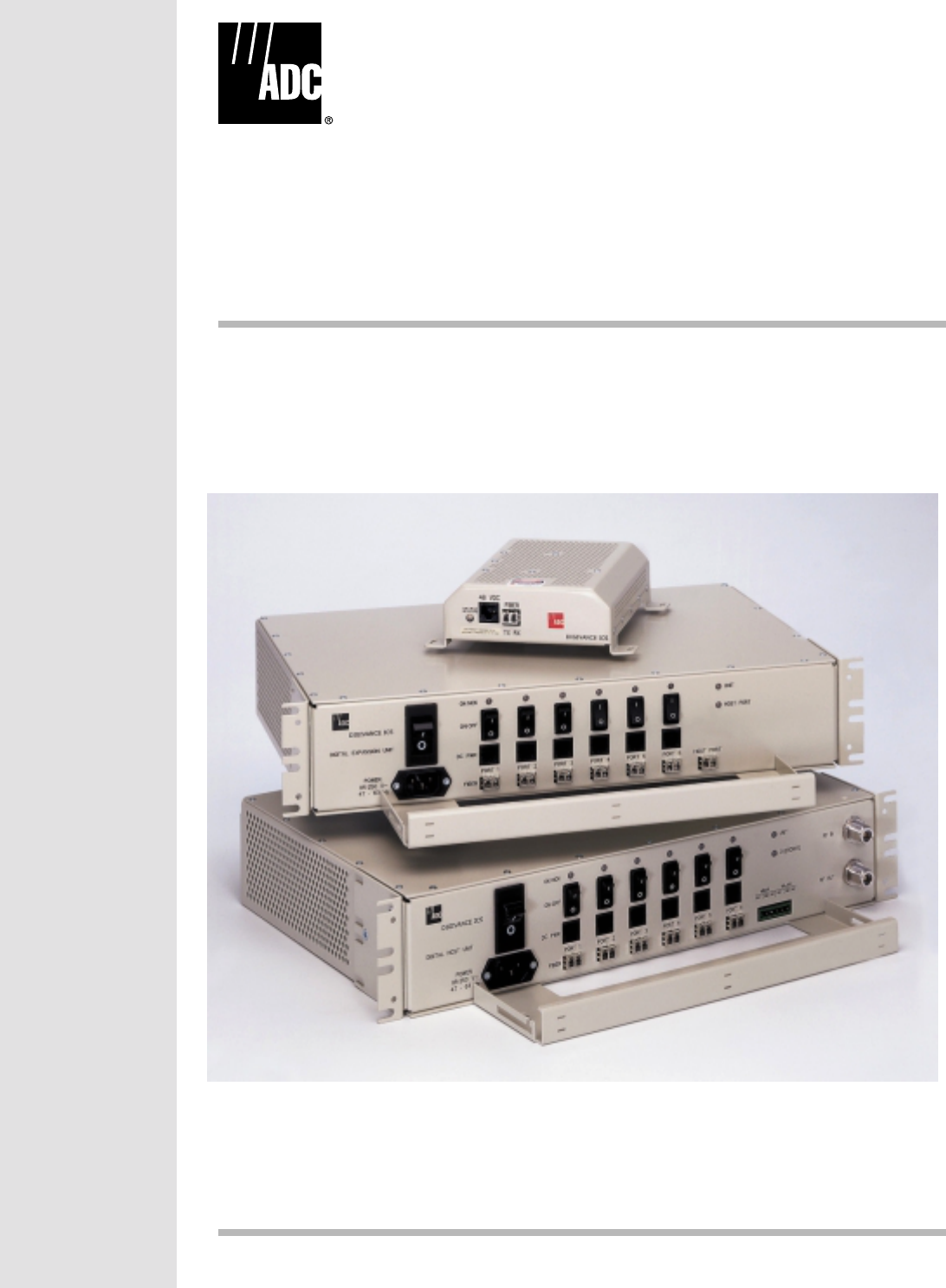
This section provides an overview of the Digivance Indoor Coverage Solution (ICS), a
description of the functions and features provided by the units that comprise the system, a
listing of terms used and their definition, and a table of specifications.
1.1 System Functional Overview
The Digivance ICS is adigitally distributed antenna system that provides in-building coverage
for analog (AMPS) or digital (TDMA or CDMA) cellular phone systems operating within the
800 MHz frequency band. Large buildings typically interfere with the transmission or
reception of cellular phone system signals by imposing high attenuation losses on RF signals.
The Digivance ICS is designed to overcome the attenuation losses that make cellular
communications within buildings or structures difficult or impossible. With the Digivance
ICS, cellular phone RF signals can be distributed to the interior areas of any building or
structure to eliminate dead spots and improve reception.
1.1.1 Basic System Components
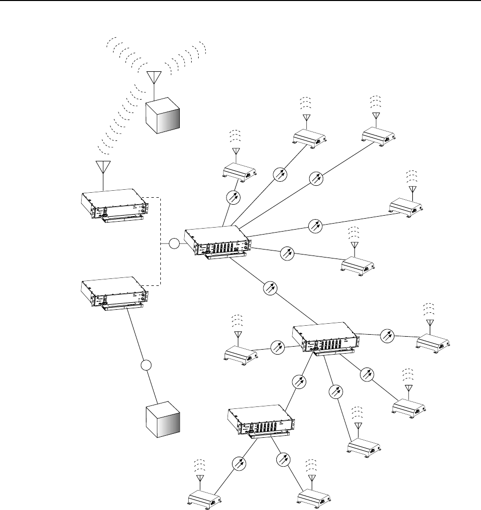
The basic components of the Digivance ICS and their functions are shown in Figure 1. The
basic system consists of the Digital Host Unit (DHU), Digital Remote Unit (DRU), and when
additional capacity or longer fiber runs are required, the Digital Expansion Unit (DEU). In
addition, two accessory items, the Local Interface Unit (LIU) and the Remote Interface Unit
(RIU) may be used as needed to interface the DHU with the cellular system Base Transceiver
Station (BTS).
1.1.2 Interface With BTS
The DHU interfaces, either locally or remotely, with the BTS. As referenced in this
publication, the BTS could be either amicrocell or a cell site base station. When the BTS
(microcell) is co-located with the DHU, alocal interface over coaxial cable is possible. An
interface device, such as the LIU, may be required to provide the proper input and output RF
signal levels between the BTS and the DHU. When the BTS (cell site base station) is not co-
located with the DHU, aremote interface using a donor antenna is required. An interface
device such as the RIU is required to provide the proper input and output RF signal levels
between the donor antenna and the DHU.
The DHU interfaces, as described in the preceding paragraph, with the BTS. In the forward
path, the DHU receives RF signals from the BTS. The DHU digitizes the RF signals and then
converts them to digital optical signals for transport to the DEUs and DRUs. In the reverse
path, the DHU receives digital optical signals from the DRUs and DEUs. The DHU converts
the optical signals back to the original RF signal format for transmission to the BTS.
ADCP-75-110 • Issue B • March 2001
Page 2
© 2001, ADC Telecommunications, Inc.
DRU
DRU
DRU
DRU
DRU
DRU
DRU
DRU
DRU
DRU
DRU
DEU
DEU
DHU
RIU
LIU
REMOTE
BTS
LOCAL
BTS
RF
Fig 1C-A
RF
Figure 1. System Overview Functional Block Diagram
1.1.3 Interface With Cellular Phones
The DRUs interface with the cellular phones. In the reverse path, the DRU receives RF signals
from each cellular phone. The DRU digitizes the RF signals and then converts them to digital
optical signals for transport to the DHU. In the forward path, the DRU receives digital optical
signals from the DHU. The DRU converts the optical signals back to the original RF signal
format for transmission to the cellular phones. Asmall antenna is connected to the DRU to
transmit and receive RF signals from the cellular phones.

ADCP-75-110 • Issue B • March 2001
Page 3
© 2001, ADC Telecommunications, Inc.
1.1.4 Digital Fiber Optic Transport
The DHU is connected to each DRU unit over a pair of multi-mode fiber optic links. One link
is used to transport the forward path optical signal. The other link is used to transport the
reverse path optical signal. Because the optical signal is digital, no adjustments to the optical
signal level are required at the DRU or the DHU regardless of the length of the optical link.
Either 50 or 62.5 micron core multi-mode fiber optic cable may be used for the optical link. If
50 micron cable is used, the optical link may be up to 750 meters in length. If 62.5 micron
core cable is used, the optical link may be up to 500 meters in length. The fiber optic links are
terminated with LC connectors.
1.1.5 Capacity for Expansion and Extended Runs
The DEU enables 6-way expansion of any optical port. This makes is possible to add more
DRUs without having to install additional DHUs. Each DHU is equipped with six optical
ports. If more than six DRUs are required by the application, aDEU may be connected to one
of the optical ports at the DHU which expands that port to six ports. If still more optical ports
are required, then asecond DEU may be connected to the DHU or a second DEU may be
connected to the first DEU. The ability to cascade DEU’s in parallel or in series provides
unlimited flexibility. It is physically possible to connect an unlimited number DRUs to the
DHU through the installation of DEUs. The maximum number of DRUs that can connected to
the DHU is limited only by the cumulative noise effect caused by antenna combining.
1.1.6 Power Requirements
The DHU, DEU, LIU, and RIU are each powered by 120–240 VAC (50–60 Hz) power which
is supplied through astandard three-conductor AC power cord. The DRU is powered by
nominal 48 VDC which is supplied by the DHU, DEU, or an AC/DC wall-mount style
converter. When the DRU is powered by the DHU or DEU, the power is fed through a
category 5 cable terminated with male RJ-45 connectors.
1.1.7 Fault Detection and Alarm Reporting
LED indicators are provided on the front panel of the various units to indicate when afault is
detected. In addition, normally open and normally closed alarm contacts (for both major and
minor alarms) are provided at the DHU for connection to acustomer provided external alarm
system. This could be a local system or automatic call-out system.
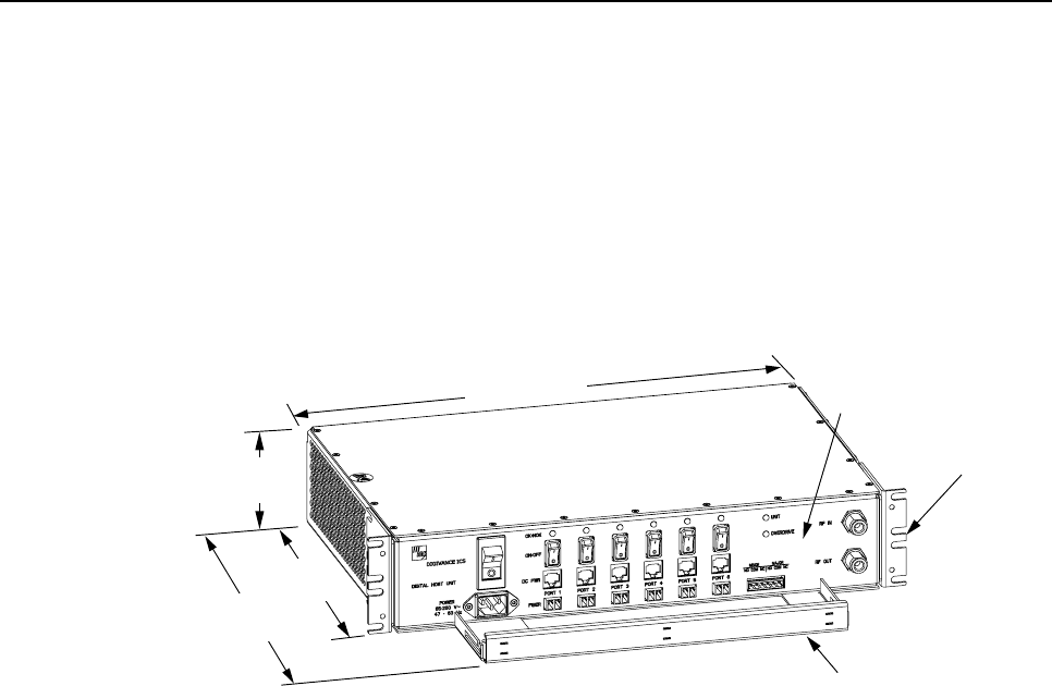
1.2 Digital Host Unit Description
The DHU, shown in Figure 2, serves as the BTS servicing unit for the Digivance ICS. The
DHU provides the following basic functions:
• RF inputs and outputs
• Optical interface to the DRUs or DEUs
• Digitizing of the cellular forward path RF signal
ADCP-75-110 • Issue B • March 2001
Page 4
© 2001, ADC Telecommunications, Inc.
• Distribution of the digitized forward path RF signals into six digitized optical signals
• Conversion of up to six reverse path digitized optical signals to six digitized RF signals
• Combining of the six digitized RF signals into a single composite digitized RF signal
• Conversion of the combined digitized RF signal to a composite cellular RF signal
• DC power for powering the DRUs
• Relay contact closures to provide alarm information to an external alarm system
17.2 INCHES
(437 mm)
3.5 INCHES
(89 mm)
11.4 INCHES
(290 mm)
15.3 INCHES
(389 mm)
FRONT PANEL
CABLE MANAGEMENT
TRAY
MOUNTING
BRACKET
(BOTH SIDES)
Fig 2A-A
Figure 2. Digital Host Unit
1.2.1 Primary Components
The DHU consists of two electronic circuit board assemblies and apower supply assembly
that are mounted within apowder-coated sheet metal enclosure. The metal enclosure provides
amounting point for the electronic assemblies, serves as aheat sink, and controls RF
emissions. Except for the fan units, the electronic circuit board assemblies are not user
replaceable. The DHU is designed for use within anon-condensing indoor environment such
as inside awiring closet or cabinet. All controls, connectors, and indicators are mounted on
the DHU front panel for convenient access. Cable management functions for the power and
fiber optic cables are provided by a cable management tray that extends outward from the
DHU front panel.
1.2.2 Mounting
The DHU may be used in both rack-mount and wall-mount applications. For rack mount
applications, apair of reversible mounting brackets is provided that allow the DHU to be
mounted in either a19-inch or 23-inch EIA or WECO equipment rack. When rack-mounted,
the front panel of the DHU is flush with the front of the rack. The cable management tray
extends 3.9 inches (99 mm) beyond the front panel. For wall-mount applications, apair of
holes is provided in the cable management tray which allow the DHU to be mounted on any
flat vertical surface. The DHU should be oriented with the front panel facing upward when
wall-mounted. Fasteners are provided for rack-mount applications.

ADCP-75-110 • Issue B • March 2001
Page 5
© 2001, ADC Telecommunications, Inc.
1.2.3 Fault Detection and Alarm Reporting
The DHU is designed to detect internal circuitry faults and optical port faults. Various front
panel Light Emitting Diode (LED) indicators turn from green to red or yellow if afault is
detected. Aset of alarm contacts (normally open and normally closed) are also provided for
reporting an alarm to an external alarm system when afault is detected. Both major alarm (all
fault conditions except high temperature) and minor alarm (high temperature fault condition)
contacts are provided.
1.2.4 RF Signal Connections
The RF signal connections between the DHU and the BTS are supported through two type N
female connectors. One connector is used for coaxial cable connection of the forward path RF
signal. The other connector is used for coaxial cable connection of the reverse path RF signal. In
most installations, the DHU will not connect directly to the BTS but will be connected to an
interface device such as the RIU or the LIU. Additional information concerning the DHU to BTS
interface is provided in the Digivance ICS Remote Interface Unit User Manual (ADCP-75-113) and
in the Digivance ICS Local Interface Unit User Manual (ADCP-75-114).
The DHU requires acomposite forward path RF signal level of –20 dBm or lower. An
overdrive limiter protects the system against excessive inputs but does not function during
normal operation. The DHU does not have Automatic Gain Control (AGC).
1.2.5 Optical and Electrical Interface Connections
Operation of the DRUs and DEUs is supported by six optical and six electrical ports. Each optical
and electrical interface connection includes astatus LED, aduplex LC type optical adapter, an RJ-
45 DC power jack, and aport enable/disable switch. An optical port may be connected to aDRU, a
DEU, or not used. An electrical port may be connected to aDRU or not used. Unused ports require
no connections at all and are disabled via the corresponding port enable/disable switch. When
disabled, the port LED is off, the alarm reporting function is disabled, the laser is off, and the DC
power is off. Enabling the enable/disable switch activates all functions.
1.2.6 Powering
The DHU is powered by 120–240 VAC (50–60 Hz) power which is supplied through a
standard three-conductor AC power cord. The power cord is provided with the DHU and is 98
inches (2.5 meters )long. Aresetable circuit breaker/On-Off switch is provided at the unit
front panel. The switch applies power to the DHU internal power supply.
1.2.7 Cooling
Continuous air flow for cooling is provided by dual fans mounted on the right side of the housing.
Aminimum of 3inches (76 mm) of clearance space must be provided on both the left and right
sides of the DHU for air intake and exhaust. An alarm is provided that indicates if ahigh
temperature condition (>70º C/ 158º F) occurs. The fans may be field-replaced if either fan fails.
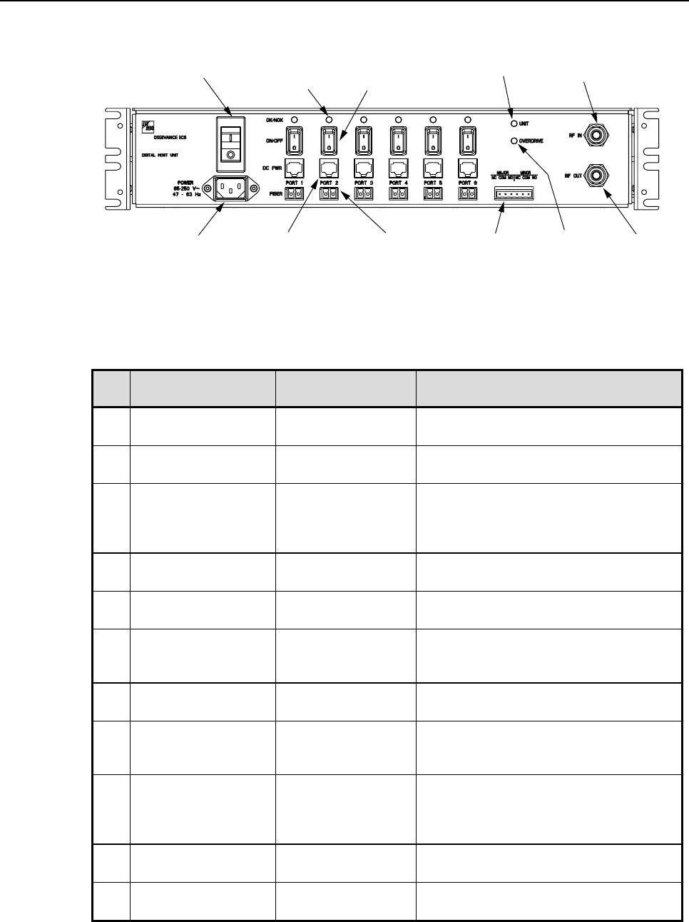
1.2.8 User Interface
The DHU user interface consists of the various connectors, switches, terminals, and LEDs that
are provided on the DHU front panel. The DHU user interface points are indicated in Figure 3
and described in Table 1.
ADCP-75-110 • Issue B • March 2001
Page 6
© 2001, ADC Telecommunications, Inc.
(1) AC POWER CORD
CONNECTOR
(2) AC POWER
ON/OFF SWITCH (3) OPTICAL PORT
LED INDICATOR
(6 PLACES)
(4) OPT/ELEC PORT
ENABLE/DISABLE
SWITCH (6 PLACES)
(5) ELECTRICAL PORT
DC POWER JACK
(6 PLACES)
(6) OPTICAL PORT
OPTICAL ADAPTERS
TX-LEFT - RX-RIGHT
(6 PLACES)
(7) UNIT LED
INDICATOR (10) RF INPUT
CONNECTOR
(8) OVERDRIVE
LED
INDICATOR
(9) ALARM
TERMINAL
STRIP
(11) RF OUTPUT
CONNECTOR
Fig 3B-A
NOTE: SHOWN WITHOUT
CABLE MANAGEMENT TRAY
Figure 3. Digital Host Unit User Interface
Table 1. Digital Host Unit User Interface
REF
No. USER INTERFACE
DESIGNATION DEVICE FUNCTIONAL DESCRIPTION
1 POWER 3-wire AC power
cord connector Used for connecting the AC power cord.
2 – I/O rocker switch/
circuit breaker Provides AC power On/Off control and
AC power over current protection.
3 OK/NOK (Ports 1–6) Multi-colored LED
(Red/Green/Yellow) Indicates if the DRU or remote DEU
connected to the optical port is normal or
faulty or if the optical inputs from the DRU
or remote DEU are normal or lost. (see Note)
4 ON/OFF (Ports 1–6) I/O rocker switch Enables or disables corresponding
electrical and optical ports.
5DCPWR (Ports 1–6) RJ-45 jack (female) Used for connecting aDRU cat 5power
cable to the designated DC power jack
6 FIBER (Ports 1–6) Duplex LC-type
fiber optic adapter Used for connecting each DEU or DRU
forward path and reverse path optical link to
the designated optical adapter.
7 UNIT Multi-colored LED
(Red/Green/Yellow) Indicates if the DHU is normal or faulty. (see
Note)
8 OVERDRIVE Multi-colored LED
(Red/Green/Yellow) Indicates when the forward path RF input
power is overdriving the DHU digitizing
circuitry (see Note)
9 MAJOR MINOR Screw-type terminal
connector (14–26
AWG)
Used for connecting an external alarm
system to the DHU. Includes normally open
(NO), normally closed (NC), and common
(COM) wiring connections.
10 RF IN N-type female RF
coaxial connector Used for connecting the forward path RF
coaxial cable to the DHU
11 RF OUT N-type female RF
coaxial connector Used for connecting the reverse path RF
coaxial cable to the DHU
Note: Adetailed description of LED operation is provided in Section 5.
ADCP-75-110 • Issue B • March 2001
Page 7
© 2001, ADC Telecommunications, Inc.
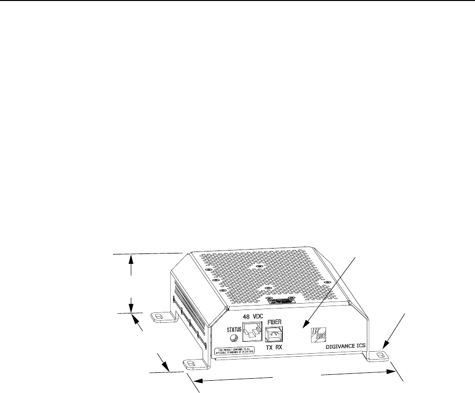
1.3 Digital Remote Unit Description
The DRU, shown in Figure 4, serves as the cellular user servicing unit for the Digivance ICS.
The DRU provides the following basic functions:
• RF interface to the cellular users via an external antenna
• Optical interface to the DHU or DEU
• Conversion of the forward path digitized optical signal to a digitized RF signal
• Conversion of the digitized forward path RF signal to the original cellular RF signal
• Digitizing of the cellular reverse path RF signal
• Conversion of the digitized reverse path RF signal to a digital optical signal output
• Transports alarm status via optical link
FRONT PANEL
MOUNTING FOOT
(EACH CORNER)
7.0 INCHES
(178 mm)
7.3 INCHES
(185 mm)
2.1 INCHES
(53 mm)
Fig 1-A
Figure 4. Digital Remote Unit
1.3.1 Primary components
The DRU consists of an electronic circuit board assembly that is mounted within apainted
sheet metal enclosure. The metal enclosure provides amounting point for the electronic
assembly, serves as aheat sink, and controls RF emissions. The electronic circuit board
assembly is not user replaceable. The DRU is designed for use within anon-condensing
indoor environment such as inside abuilding. All controls, connectors, and indicators (except
the antenna connector) are mounted on the DRU front panel for convenient access.
1.3.2 Mounting
The DRU is equipped with four integral mounting feet that allow it to be mounted on any flat
horizontal or vertical surface. Atypical location for mounting the DRU would be above
ceiling tiles where the optical fiber and power cables can be concealed or on a wall. Slots are
provided in the mounting feet for securing the DRU to the mounting surface.

ADCP-75-110 • Issue B • March 2001
Page 8
© 2001, ADC Telecommunications, Inc.
1.3.3 Fault Detection
The DRU is designed to detect internal circuitry faults or loss of system inputs. A front panel
LED indicator turns from green to red when afault condition is detected or when the system
optical input is lost. The DRU sends the fault information to the DHU over the fiber optic
link. A corresponding port LED at the DHU turns red when the DRU reports a fault.
1.3.4 RF Signal Interface
The RF signal interface between the DRU and the cellular users is provided through an
external antenna connected to afemale SMA connector. The antenna which must be ordered
separately. Several types of antennas with various patterns are available. Non-ADC antennas
may also be used with the DRU to meet various application requirements.
1.3.5 Optical Port
The DRU is equipped with aduplex LC type optical adapter that provides apoint for
connecting the optical link cables. Depending on the application requirements, the optical
adapter may be connected to either a DHU or a DEU.
1.3.6 Powering
The DRU is equipped with afemale RJ-45 jack that provides apoint for connecting aDC
power cable. The DRU is powered by nominal 48 VDC power which is supplied through the
RJ-45 connector. Power to the DRU may be supplied by the DHU, DEU, or by a 120 VAC to
48 VDC power converter (available separately as an accessory item) plugged into a properly
grounded 120 VAC outlet. The AC/DC converter is aUL Listed stand alone Limited Power
Supply (LPS) unit with arated output of 48 VDC at 1.2 A. When powered by the DHU or
DEU, a category 5 twisted-pair cable terminated with RJ-45 connectors is required.
1.3.7 Cooling
The DRU is cooled by natural convection air flow. The DRU mounting feet are designed to provide
clearance under the unit so that air can enter the DRU enclosure from the bottom and exit through
the top. Aminimum clearance of 3inches (76 mm) must be provided on all sides of the DRU
(except the bottom) to ensure there is adequate air circulation for cooling. In addition, at least one
surface of the DRU installation area must be open to the interior of the building.
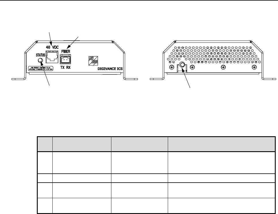
1.3.8 User Interface
The DRU user interface consists of the connectors and the LED that are provided on the DRU
front and rear panels. The DRU user interface points are indicated in Figure 5 and described in
Table 2.
ADCP-75-110 • Issue B • March 2001
Page 9
© 2001, ADC Telecommunications, Inc.
Fig 5B-A
REAR VIEWFRONT VIEW
(4) ANTENNA CONNECTOR
(1) STATUS LED
(2) 48 VDC POWER
CONNECTOR (3) FIBER LINK
OPTICAL ADAPTERS
TX-LEFT - RX-RIGHT
Figure 5. Digital Remote Unit User Interface
Table 2. Digital Remote Unit User Interface
REF
No. USER INTERFACE
DESIGNATION DEVICE FUNCTIONAL DESCRIPTION
1 STATUS Multi-colored LED
(Red/Green/Yellow) Indicates if the status of the DRU is
normal or faulty or if the forward path
optical input is normal or lost. (see Note)
248VDC RJ-45 jack (female) Used for connecting a DC power cable
3 FIBER
TX RX Duplex LC-type
fiber optic adapter Used for connecting the forward path and
reverse path optical links
4 – SMA-type coaxial
connector (female) Used for connecting the antenna coaxial
cable lead
Note: Adetailed description of LED operation is provided in Section 5.
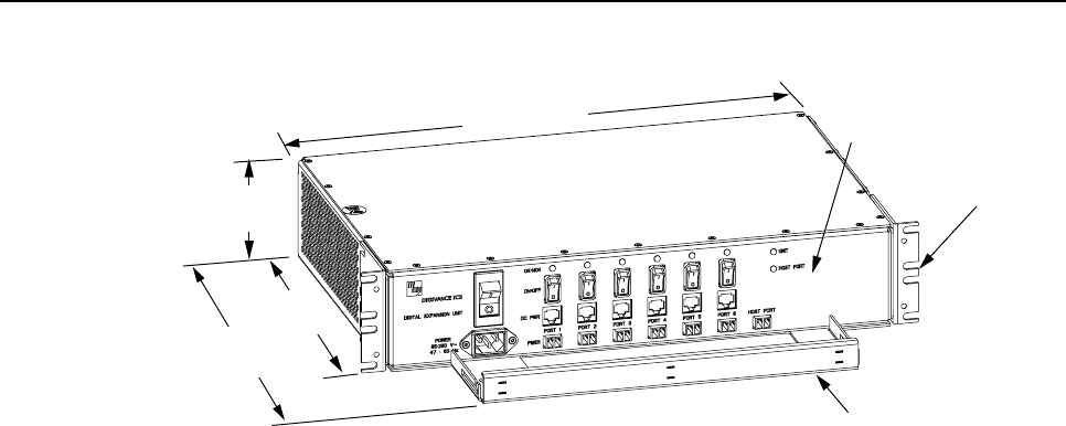
1.4 Digital Expansion Unit Description
The DEU, shown in Figure 6, serves as aservice expansion unit and line extender for the
Digivance ICS. The DEU provides the following basic functions:
• Optical interface to the DHU and up to six DRUs or DEUs
• Conversion of the forward path digitized optical signal to an electrical bit stream
• Splitting of the electrical bit stream into six separate bit streams
• Conversion of the six forward path electrical bit streams into six digital optical signals
• Conversion of up to six reverse path digital optical signals into six serial bit streams
• Combining of the six reverse path serial bit streams into a single digital composite signal
• Conversion of the single digital composite signal to a digital optical signal
• DC power for powering the DRUs
• Alarm transport via the optical links
ADCP-75-110 • Issue B • March 2001
Page 10
© 2001, ADC Telecommunications, Inc.
FRONT PANEL
CABLE MANAGEMENT
TRAY
MOUNTING
BRACKET
(BOTH SIDES)
Fig 6B-A
3.5 INCHES
(89 mm)
11.4 INCHES
(290 mm)
15.3 INCHES
(389 mm)
17.2 INCHES
(437 mm)
Figure 6. Digital Expansion Unit
1.4.1 Primary Components
The DEU consists of two electronic circuit board assemblies that are mounted within a
powder-coated sheet metal enclosure. The metal enclosure provides amounting point for the
electronic assemblies and serves as aheat sink. Except for the fan units, the electronic circuit
board assemblies are not user replaceable. The DEU is designed for use within a non-
condensing indoor environment such as inside awiring closet or within an environmentally
controlled cabinet. All controls, connectors, and indicators are mounted on the DEU front
panel for convenient access. Cable management functions for the power and fiber optic cables
are provided by a cable management tray that extends outward from the DEU front panel.
1.4.2 Mounting
The DEU may be used in both rack-mount and wall-mount applications. For rack mount
applications, apair of reversible mounting brackets is provided that allow the DEU to be
mounted in either a19-inch or 23-inch EIA or WECO equipment rack. When rack-mounted,
the front panel of the DEU is flush with the front of the rack. The cable management tray
extends 3.9 inches (99 mm) beyond the front panel. For wall-mount applications, apair of
holes is provided in the cable management tray which allow the DEU to be mounted on any
flat vertical surface. The DEU should be oriented with the front panel facing upward when
wall-mounted. Fasteners are provided for rack-mount applications.
1.4.3 Fault Detection
The DEU is designed to detect internal circuitry faults and optical port faults. Various front
panel Light Emitting Diode (LED) indicators turn from green to red or yellow when afault is
detected The DEU transports the fault information to the DHU or supporting DEU over the
fiber optic link. Acorresponding port LED at the DHU or DEU turns from green to red when
the DEU reports a fault.
ADCP-75-110 • Issue B • March 2001
Page 11
© 2001, ADC Telecommunications, Inc.
1.4.4 Optical and Electrical Interface Connections
Operation of the DRUs and DEUs is supported by six optical and six electrical ports. Each optical
and electrical interface connection includes astatus LED, aduplex LC type optical adapter, an RJ-
45 DC power jack, and aport enable/disable switch. An optical port may be connected to aDRU, a
DEU, or not used. An electrical port may be connected to aDRU or not used. Unused ports require
no connections at all and are disabled via the corresponding port enable/disable switch. When
disabled, the port LED is off, the alarm reporting function is disabled, the laser is off, and the DC
power is off. Enabling the enable/disable switch activates all functions.
1.4.5 Powering
The DEU is powered by 120–240 VAC (50–60 Hz) power which is supplied through a
standard three-conductor AC power cord. The power cord is provided with the DEU and is 2.5
meters (98 inches) long. Aresetable circuit breaker/On-Off switch is provided at the unit front
panel. The switch applies power to the DEU internal power supply.
1.4.6 Cooling
Continuous air flow for cooling is provided by dual cooling fans mounted on the right side of
the sheet metal housing. Aminimum of 3 inches of clearance space must be provided on both
the left and right sides of the DEU for air intake and exhaust. An alarm is provided that
indicates if ahigh temperature condition occurs. The cooling fans may be field-replaced if
either unit fails.
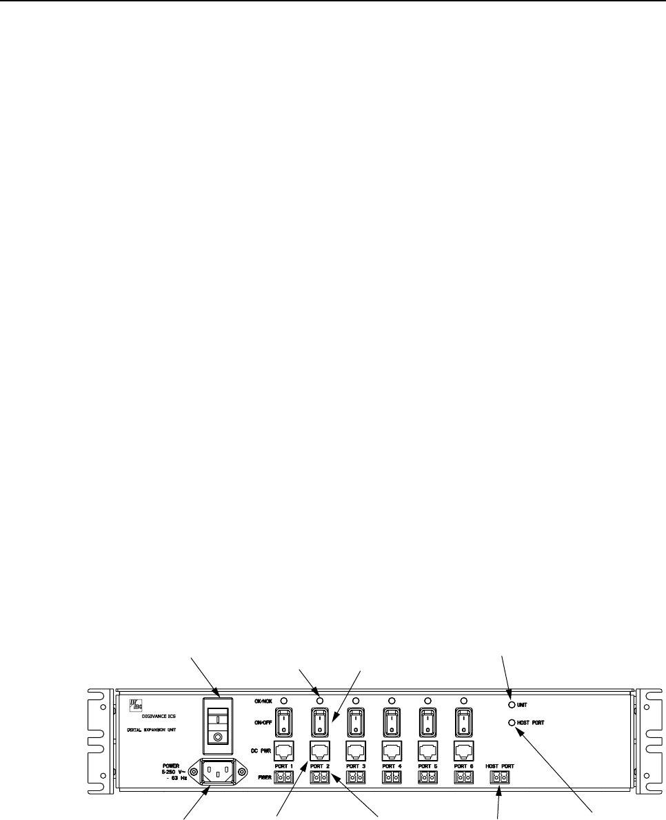
1.4.7 User Interface
The DEU user interface consists of the various connectors, switches, and LEDs that are
provided on the DEU front panel. The DEU user interface points are indicated in Figure 7 and
described in Table 3.
Fig 7B-A
(2) AC POWER
ON/OFF SWITCH (3) OPTICAL PORT
LED INDICATOR
(6 PLACES)
(4) OPT/ELEC PORT
ENABLE/DISABLE
SWITCH (6 PLACES)
(7) UNIT LED
INDICATOR
(1) AC POWER CORD
CONNECTOR (5) ELECTRICAL PORT
DC POWER JACK
(6 PLACES)
(6) OPTICAL PORT
OPTICAL ADAPTERS
TX-LEFT - RX-RIGHT
(6 PLACES)
(8) HOST PORT
LED
INDICATOR
(7) HOST PORT
OPTICAL ADAPTERS
TX-LEFT - RX-RIGHT
NOTE: SHOWN WITHOUT
CABLE MANAGEMENT TRAY
Figure 7. Digital Expansion Unit User Interface

ADCP-75-110 • Issue B • March 2001
Page 12
© 2001, ADC Telecommunications, Inc.
Table 3. Digital Expansion Unit User Interface
REF
No. USER INTERFACE
DESIGNATION DEVICE FUNCTIONAL DESCRIPTION
1 POWER 3-wire AC power
cord connector Used for connecting the AC power cord
2 – I/O rocker switch/
circuit breaker Provides AC power On/Off control and
AC power over current protection
3 OK/NOK (Ports 1–6) Multi-colored LED
(Red/Green/Yellow) Indicates if the DRU or remote DEU
connected to the optical port is normal or
faulty or if the optical inputs from the DRU
or remote DEU are normal or lost. (see Note)
4 ON/OFF (Ports 1–6) I/O rocker switch Enables or disables corresponding
electrical and optical ports
5DCPWR (Ports 1–6) RJ-45 connector
(female) Used for connecting aDRU cat 5power
cable to the designated DC power jack
6 FIBER (Ports 1–6) Duplex LC-type
fiber optic adapter Used for connecting each DRU or remote
DEU forward path and reverse path optical
link to the designated optical port
7 HOST PORT Duplex LC-type
fiber optic adapter Used for connecting the DHU or supporting
DEU forward path and reverse path optical link
8 UNIT Multi-colored LED
(Red/Green/Yellow) Indicates if the DEU is normal or faulty. (see
Note)
9 HOST PORT Multi-colored LED
(Red/Green/Yellow) Indicates if the optical inputs from the
DHU or supporting DEU are normal or
faulty. (see Note)
Note: A detailed description of LED operation is provided in Section 5.
1.5 Terms and Definitions
Refer to Table 4 for a listing of the terms used in this manual and their definition.
Table 4. Terms and Definitions
TERM DEFINITION
Alarm Response The response to an alarm input.
Base Transceiver Station The radio equipment that transmits and receives the voice and
control channels to and from the cellular handsets.
Composite Signal The sum of several combined signals.
Digital Expansion Unit The unit that extends a single optical interface to multiple optical
interfaces or that extends an optical run.
Digital Host Unit The unit that converts and provides the digital source signal to all DEUs
and DRUs and converts summed inputs from DEUs and DRUs.
(Continued)
Table 4. Terms and Definitions (Continued)

ADCP-75-110 • Issue B • March 2001
Page 13
© 2001, ADC Telecommunications, Inc.
TERM DEFINITION
Digital Remote Unit The unit that interfaces the in-building user to the Digivance
optical transport
Digitized RF Signal The RF signal in a digitized form.
Forward Path Signal A signal that travels from the base station to the cell phone.
Major Alarm An alarm condition that applies when any fault (except high
temperature) occurs.
Minor Alarm The alarm condition that applies when a high temperature condition
occurs. (> 70º C/158º F)
Mute To force a forward path RF signal to a “no signal” state
Normal State The operating state after power-up is completed and no faults are
detected.
Port An RF, optical, or electrical interface point.
Port Alarm A fault that affects only the unit connected to that port.
Power-Up State The period between the application of power to a unit and the
normal state. This period includes time for circuit stabilization and
initialization operations.
Reverse Path Signal A signal that travels from one or more cell phones to the base station.
Transport Alarm Signal An alarm signal transported over the fiber optic link.
Unit Alarm A fault within a unit that usually affects all connected ports.
1.6 Specifications
Refer to Table 5 for the Digivance ICS system specifications.
Table 5. System Specifications
PARAMETER SPECIFICATION REMARKS
Optical - All Units
Fiber type Multimode 50 or 62.5 micron core Two fibers per link
Maximum Fiber Length 500 m
750 m
With 62.5 micron core
With 50 micron core
Optical Output Power –10 to +4 dBm
Optical Wavelength 850 nm
Environmental
Operating Temperature 0º to 50º C (32º to 122º F)
Storage Temperature –30º to +70º C (–22 to 158º F)
Humidity No condensation
Weather resistance Indoor installation only
(Continued)

ADCP-75-110 • Issue B • March 2001
Page 14
© 2001, ADC Telecommunications, Inc.
Table 5. System Specifications (Continued)
PARAMETER SPECIFICATION REMARKS
RF Forward Path
System Bandwidth 25 MHz
Frequency range Cellular: 869 to 894 MHz
Output power +13 +/– 1 dB composite
Gain variation +/– 3 dB
< 1.5 dB variation
Over frequency, temperature,
and unit-
Per 1.25 MHz CDMA channel
IP3> +35 dBm
CDMA ACPR1 < –45 dBc
Spurious Output < –35 dBm
DHU input signal level –20 dBm maximum Provides a +13 dBm RF output
signal at the DRU
RF Reverse Path
System bandwidth 25 MHz
Frequency Range US Cellular: 824 to 849 MHz
Gain 10 +/– 1 dB
Gain Variation +/– 3 dB
< 1.5 dB variation
Over frequency, temperature,
and unit-unit
Per 1.25 MHz CDMA channel
Automatic Gain
Limiting Prevents A/D saturation with
large inputs. Disabled for
composite RF input < –40 dBm
Noise Figure < 12 dB 10 + 10 log n (n = # of users)
DHU output signal level –30 dBm maximum With a –40 dBm composite
maximum input signal at the
DRU
Physical/Electrical - DHU
Weight 17.5 lbs (7.9 kg)
RF connection Type N female
Alarm connection Screw terminals (14–26 AWG) NO, NC, and COM
Optical connection Duplex LC adapter
DC power connection RJ-45 female
Power source 120–240 VAC, 50–60 Hz
Power consumption 24 W typical
Current rating 85–250 VAC, 2 Amp input
(Continued)

ADCP-75-110 • Issue B • March 2001
Page 15
© 2001, ADC Telecommunications, Inc.
Table 5. System Specifications (Continued)
PARAMETER SPECIFICATION REMARKS
Physical/Electrical - DEU
Weight 17.5 lbs (7.9 kg)
Optical connection Duplex LC adapter
DC power connection RJ-45 female
Power source 120–240 VAC, 50–60 Hz
Power consumption 22 W typical
Current rating 85–250 VAC, 2 Amp input
Physical/Electrical -
DRU
Weight 2 lbs (0.9 kg)
RF connection SMA female
Antenna types Ceiling mount omnidirectional
Directional panel
90º directional panel
Ceiling mount hallway
Center mount (2.5 dBi gain)
Wall mount (8 dBi gain)
Corner mount (7.5 dBi gain)
Center mount( 4 dBi gain)
Optical connection Duplex LC adapter
DC power connection RJ-45 female
Power source 48 +/– 1 VDC nominal 48 VDC
Power consumption 17 W typical
Current rating 48 VDC, 350 mA input

ADCP-75-110 • Issue B • March 2001
Page 16
© 2001, ADC Telecommunications, Inc.
2 INSTALLATION PLANNING AND SYSTEM DESIGN
This section provides installation planning information and basic system design recommendations
for RF engineers that will be designing and installing an in-buildling coverage solution using the
Digivance ICS. System design and planning services are available from ADC if required. Refer to
section 6of this manual for additional information.
2.1 Base Station Interface Requirements
The DHU may be interfaced either locally or remotely with the BTS. As referenced in this
publication, the BTS could be either amicrocell or a cell site base station. With alocal
interface, ahard-wire connection is provided between the DHU and the BTS (microcell) using
coaxial cables. With aremote interface, an over-the-air connection is provided between the
DHU and the BTS (cell site base station) using a donor antenna.
2.1.1 Local BTS (Microcell) Interface
Alocal interface between the DHU and the BTS (microcell) over coax requires specific RF
input and output signal levels at the DHU and BTS. The correct levels can be provided at the
BTS and DHU using the Local Interface Unit (LIU). The LIU is an accessory item that
provides adjustable gain or attenuation in both the RF forward and reverse path. The level of
the RF output signal from the BTS will vary depending on the type of BTS. Therefore, it will
generally be necessary to add some gain or some attenuation to the forward path (downlink)
signal to provide the recommended composite maximum RF input signal level at the DHU
which is–20 dBm.When the level of the RF input signal at the DHU is –20 dBm, the level of
the RF output signal at the DRU will be +13 dBm which is the maximum allowed.
In the reverse path, the input signal level required at the BTS will also vary depending on the
type of BTS. When the level of the reverse path (uplink) signal at the DRU is at the
recommended composite maximum of –40 dBm,the level of the RF output signal from the
DHU is –30 dBm.Therefore, it may be necessary to add some gain or attenuation to the
reverse path signal in order to achieve the required RF input signal level at the BTS. Ablock
diagram showing a typical local DHU to BTS interface is provided in Figure 8.
LOCAL
INTERFACE
UNIT
FORWARD
(DOWNLINK)
REVERSE
(UPLINK)
+13 dBm
(COMPOSITE
MAX)
-40 dBm
(COMPOSITE
MAX)
-20 dBm
(COMPOSITE
MAX)
-30 dBm
(COMPOSITE
MAX)
Fig 8B-A
DIGITAL
HOST
UNIT
OPTICAL LINK
OPTICAL LINK
DIGITAL
REMOTE
UNIT
DIRECTIONAL ANTENNA
TO/FROM HANDSETS
LOCAL BASE
TRANSCEIVER
STATION
(MICRO CELL)
T1 LINK
TO SWITCH
Figure 8. Local BTS Interface Block Diagram

ADCP-75-110 • Issue B • March 2001
Page 17
© 2001, ADC Telecommunications, Inc.
The LIU is rack or wall mountable and is powered by 120–240 VAC (50–60 Hz) power. Refer
to the Digivance Local Interface Unit User Manual (ADCP-75-113) for acomplete description
of the LIU.
2.1.2 Remote BTS (Cell Site Base Station) Interface
Aremote interface between the DHU and the BTS (cell site base station) via a donor antenna
requires specific RF input and output signal levels at the DHU and antenna. The correct levels
at the DHU and antenna can be provided using the Remote Interface Unit (RIU). The RIU is
an accessory item that provides adjustable gain or attenuation in both the RF forward and
reverse paths. The RIU connects to adirectional antenna through aduplexer which provides
separate forward and reverse path connections for the DHU. In the forward path (downlink),
the RIU provides the recommended composite maximum RF input signal level at the DHU
which is –20 dBm.When the level of the RF input signal at the DHU is –20 dBm, the level of
the RF output signal at the DRU is +13 dBm which is the maximum allowed.
In the reverse path, the required RF output signal level to the donor antenna will vary
depending on the distance from the BTS. When the level of the reverse path (uplink) signal at
the DRU is at the recommended composite maximum level of –40 dBm,the level of the RF
output signal from the DHU is –30 dBm.Therefore, it may be necessary to add some gain or
attenuation to the reverse path signal in order to achieve the required output signal level at the
RIU antenna port. Ablock diagram showing atypical remote DHU to BTS interface is
provided in Figure 9.
The RIU is rack or wall mountable and is powered by 120–240 VAC (50–60 Hz) power. Refer
to the Digivance Remote Interface Unit User Manual (ADCP-75-114) for acomplete
description of the RIU.
DIRECTIONAL
ANTENNA TO/FROM
CELL SITE BTS
Fig 9B-A
REMOTE
INTERFACE
UNIT
FORWARD
(DOWNLINK)
REVERSE
(UPLINK) +13 dBm
(COMPOSITE
MAX)
-40 dBm
(COMPOSITE
MAX)-20 dBm
(COMPOSITE
MAX)
-30 dBm
(COMPOSITE
MAX)
DIGITAL
HOST
UNIT
OPTICAL LINK
OPTICAL LINK
DIGITAL
REMOTE
UNIT
DIRECTIONAL ANTENNA
TO/FROM HANDSETS
Figure 9. Remote BTS Interface Block Diagram

ADCP-75-110 • Issue B • March 2001
Page 18
© 2001, ADC Telecommunications, Inc.
2.2 Location and Mounting Requirements
2.2.1 DHU and DEU Location and Mounting Requirements
The DHU and the DEU may be either rack mounted or wall mounted. Fasteners (both metric
and US standard) are included with each unit for rack mount applications. Apair of reversible
mounting brackets is provided that allows the unit to be mounted in either a19-inch or 23-inch
EIA or WECO equipment rack. When rack-mounted, the front panel of the unit is flush with
the front of the rack. The cable management tray extends 3.9 inches (99 mm) beyond the front
panel. Both the DHU and DEU occupy 3.5 inches (89 mm) of rack space. Make sure the
mechanical loading of the rack will be even to avoid ahazardous condition such as aseverely
unbalanced rack. The rack should safely support the combined weight of all the equipment it
holds.
For wall-mount applications of the DHU or DEU, apair of holes is provided in the cable
management tray that allows the unit to be mounted on any flat vertical surface. The mounting
holes are spaced 11.66 inches (296 mm) apart. Orient the DHU/DEU so the front panel faces
up when mounted. Appropriate fasteners for wall mounting must be provided by the installer.
It is recommended that abacker board such as 3/4-inch plywood be installed over the
mounting surface to provide a secure base for attaching the DHU or DEU.
Mount the DHU and DEU in anon-condensing indoor environment such as inside awiring
closet or within an environmentally controlled cabinet. All controls, connectors, and indicators
are mounted on the front panel. Route all cables to the front panel for connection. Use the
cable retainers provided on the cable management tray to secure the fiber optic, DC power,
and local alarm system cables.
The maximum recommended ambient temperature for the DHU and DEU is 50º C (122º F).
Allow sufficient air circulation or space between each unit when installed in amulti-unit rack
assembly because the operating ambient temperature of the rack environment might be greater
than room ambient. Provide aminimum clearance of 3 inches (76 mm) on both the left and
right sides of the unit for air intake and exhaust. Refer to Figure 2 for the DHU dimensions
and Figure 6 for the DEU dimensions.
2.2.2 DRU Location and Mounting Requirements
The DRU may be wall-mounted or ceiling-mounted. The DRU is equipped with four integral
mounting feet that allow it to be fastened to any flat vertical or horizontal surface. Holes are
provided in the mounting feet for inserting fasteners. Appropriate fasteners for securing the
DRU to the selected mounting surface must be provided by the installer.
Mount the DRU in anon-condensing indoor environment. Route the DC power cable and fiber
optic links to the DRU front panel for connection. Route the antenna coaxial cable to the DRU
rear panel for connection. Provide aminimum of 3 inches (76 mm) of clearance space (more if
cover will be required) on all sides of the DRU (except the bottom) to ensure there is adequate
air circulation for cooling. In addition, at least one surface of the DRU installation area must
be open to the interior of the building. Refer to Figure 4 for the DRU dimensions.

ADCP-75-110 • Issue B • March 2001
Page 19
© 2001, ADC Telecommunications, Inc.
2.3 Powering Requirements
2.3.1 DHU and DEU Powering
The DHU and DEU are powered by 120–240 VAC (50–60 Hz) which is supplied through a
standard three-conductor AC power cord. The 120 VAC power cord is provided with the unit
and is 98 inches (2.5 m) long. The DHU has a power consumption rating of 24 watts and the
DEU has a power consumption rating of 22 watts.Locate each unit so that an AC outlet is
within the reach of the power cord.
If back-up powering is required, it is recommended that the building Uninterruptible Power
Supply (UPS) system be used to provide back-up power to the DHU and DEU in the event of
an AC power outage.
2.3.2 DRU Powering
The DRU is powered by 48 VDC power which is supplied to the DRU through the front panel
RJ-45 connector. Power to the DRU may be provided by the DHU, DEU, or by a 120 VAC to
48 VDC power converter (available separately as an accessory item) plugged into a properly
grounded 120 VAC outlet. The DRU has a power consumption rating of 17 watts.
If the DRU will be powered by the DHU or DEU, the power cable must be fabricated on-site
by the installer. Use category 5twisted pair cable as the power supply cable when the DRU is
powered by the DHU or DEU. Route the power cable between the power source and the DRU.
Terminate both ends of the power cable with a male RJ-45 connector.
The DRU may be powered locally by the AC/DC converter, shown in Figure 10, which is available
as an accessory item. The converter is aUL Listed stand alone Limited Power Supply (LPS) unit
with arated output of 48 VDC at 1.2 A. The converter is equipped with a6-foot (1.8 m) DC power
cable which is terminated with an RJ-45 male connector. The converter is powered by 120–240
VAC (50–60 Hz) power which is supplied though astandard three-conductor AC power cord. The
120 VAC power cord is 6feet (1.8 m) long and is provided with the converter.
15988-A
Figure 10. AC/DC Power Converter

ADCP-75-110 • Issue B • March 2001
Page 20
© 2001, ADC Telecommunications, Inc.
2.4 Optical Options and Requirements
Each DHU and its associated DEUs and DRUs are connected over a pair of fiber optic links.
One link transports the forward path optical signal and the other link transports the reverse
path optical signal. Either 50 or 62.5 micron core multi-mode fiber optic cable may be used
for the optical link. If 50 micron cable is used, the optical link may be up to 750 meters
(2,460.75 ft) in length. If 62.5 micron cable is used, the optical link may be up to 500 meters
(1,640.5 ft) in length.
Whenever possible, use conduit or aguideway such as the FiberGuide system to route the optical
links between the DHU, the DEUs, and the DRUs. Avoid routing optical fibers through ladder type
cable racks or troughs that do not provide sufficient support to limit bending or prevent accidental
damage. Tie-wrapping is not recommended as ameans of securing fiber optic cables. Provide
sufficient slack at each unit for connecting each fiber to the required port. Fibers may be pre-
terminated or terminated on-site using field-installable LC type connectors.
2.5 Coaxial Cable Requirements
The DHU interfaces either locally (see Figure 8) or remotely (see Figure 9) with the BTS
through coaxial cable connections. In alocal interface with the BTS, coaxial cables are
required to link the DHU with the LIU and the LIU with the BTS. In aremote interface,
coaxial cables are required to link the DHU with the RIU and the RIU with the donor antenna.
The DHU, LIU, and RIU are equipped with N-type female connectors for connecting the
forward and reverse path coaxial cables. Use high performance, flexible, low loss 50-ohm
coaxial communications cable (RG 400 or equivalent) for all connections.
2.6 System Expansion Planning
The DEU enables 6-way expansion of any optical port. This makes is possible to add more
DRUs without having to install additional DHUs. Each DHU is equipped with six optical
ports. If more than six DRUs are required by the application, aDEU may be connected to one
of the optical ports at the DHU which expands that port to six ports. If still more optical ports
are required, then asecond DEU may be connected to the DHU or a second DEU may be
connected to the first DEU. The ability to cascade DEU’s in parallel or in series provides
unlimited flexibility. It is physically possible to connect an unlimited number DRUs to the
DHU through the installation of DEUs.
The total number of DRU’s that can be served is limited by the cumulative noise effect caused
by antenna combining. This number cannot be determined until the radius distance of
coverage required at the DRU antenna is determined and the path loss attributed to the
structure are known. The system design requires that the carrier to noise differential be greater
than the customer’s desired signal to noise ratio.
If it is likely that the system will be expanded in the future, locate the DHU in such away that it can
either be used as ahub for an expanded system or replaced with aDEU which is then connected to a
relocated DHU. It should also be noted that aDEU can be used as an optical regenerator. ADRU
may sometimes need to be located at apoint that is beyond the 500 or 750 meter limit (depending
on fiber type) imposed by the optical link. The solution is to install aDEU at the maximum optical
link limit (500 or 750 meters) from the DHU. This provides an additional 500 or 750 meters of
optical link beyond the DEU for connecting the DRU.
ADCP-75-110 • Issue B • March 2001
Page 21
© 2001, ADC Telecommunications, Inc.
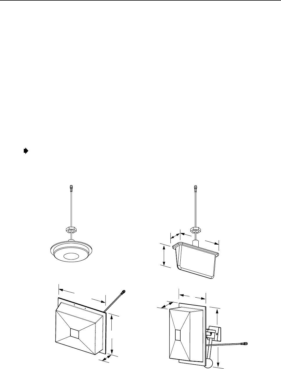
2.7 DRU Antenna Options
Four antennas, shown in Figure 11, are available from ADC for use with the DRU. All
antennas include a 6 foot (1.8 m) long 50-ohm coaxial cable (equipped with SMA male
connector) for connection to the DRU. The DRU is equipped with an SMA female connector
for connecting the antenna cable.
The DRU antennas are designed for unobtrusive mounting within an office environment. Each
type of antenna provides aspecific coverage pattern in order to accommodate the shape of the
area where coverage is required. The ceiling-mount omnidirectional antenna provides 2.5 dBi
of gain and is designed to mount in the center of the coverage area. The directional panel
antenna provides 8 dBi of gain and is designed to mount vertically on one side of the coverage
area. The 90º panel antenna provides 7.5 dBi of gain and is designed to mount vertically in the
corner of the coverage area. The ceiling mount hallway antenna provides 4 dBi of gain and is
designed to mount in the center of long corridors. Other antennas other than those offered by
ADC may also be used if required.
Note:To comply with Maximum Permissible Exposure (MPE) requirements, antennas must
be installed to provide at least 20 centimeters of separation from all persons per FCC 47 CFR
part 2.1091.
6.14 INCH DIAMETER
1.05 INCH DEPTH
MOUNTING STUD
LENGTH - 1.5 INCHES
7.26 INCHES
3.88 INCHES
2.26 INCHES
8.65 INCHES
6.55 INCHES
2.38 INCHES
7.90 INCHES
2.38 INCHES
8.65 INCHES
CEILING-MOUNT
HALLWAY
CEILING-MOUNT
OMNIDIRECTIONAL
DIRECTIONAL PANEL
(WALL-MOUNT)
90 DEGREE DIRECTIONAL
(CORNER MOUNT)
MOUNTING STUD
LENGTH - 3.85 INCHES
ALL ANTENNAS ARE EQUIPPED WITH
A 72-INCH RG58/U CABLE TERMINATED
WITH A MALE SMA CONNECTOR
MOUNTING STUD
LENGTH - 1.5 INCHES
16237-A
Figure 11. DRU Antenna Options

ADCP-75-110 • Issue B • March 2001
Page 22
© 2001, ADC Telecommunications, Inc.
2.8 Local Alarm System Reporting Requirements
The DHU provides normally open (NO) and normally closed (NC) dry alarm contacts for
reporting minor and major alarms to an external alarm system. Aminor alarm is defined as a
high temperature condition. Amajor alarm is defined as any fault condition except high
temperature. Connections to the alarm contacts are provided through a screw-type terminal
strip. Use #26 AWG insulated solid copper wire for the alarm wires. If an external alarm
system is not in use, no alarm connections are required.
2.9 Maintenance Requirements
The Digivance ICS requires no regular maintenance to insure continuous and satisfactory
operation. Maintenance, as it applies to the Digivance ICS, primarily involves diagnosing and
correcting service problems as they occur. Faults and failures arising from within the
Digivannce ICS will generate an external alarm response which includes lighting an LED
indicator(s) and closing or opening aset of alarm contacts. When an alarm is reported, it will
be necessary to isolate the source of the problem by observing the LED indicators on each unit
and then performing specified tests to isolate the problem. Once the source of the fault is
isolated, the appropriate action can be taken to correct the problem. The only unit components
that can be replaced are the cooling fans which mount in the DHU and the DEU. The failure of
any other component within aunit will require replacement of the unit. Basic troubleshooting
procedures are provided in section 5 of this manual.
2.10 System Design Recommendations
Follow asystematic process when designing an in-building coverage solution. The following
sub sections outline the four phases of the in-building coverage solution design process.
System design and planning services are available from ADC if required. Refer to section 6of this
manual for additional information.
2.10.1 Phase One - Initial Evaluation
Qualify the Installation: Confirm that there are no extenuating circumstances that would
prevent asuccessful installation such as: extreme cellular system issues (blocking, severe
interference, site problems, etc.), building issues, power issues, or safety issues (site should
not present any hazards or conditions that would make operation of the equipment unsafe).
Analyze the RF Situation: Determine how the system RF link to the outside world will be
provided. Will it be a direct feed from aBTS (microcell) or an over-the-air connection via a
donor antenna? If it is a donor antenna, is the customer within the coverage footprint of a
serving cell or better? The coverage can be determined during the preliminary walkthrough by
checking the downlink Received Signal Strength Indication (RSSI) outside the building with a
unity gain sampling antenna. Sometimes arooftop reading is needed to obtain asufficient
signal level. Note that it is an FCC violation to expand the normal coverage footprint of a
cellular site with an in-building product. In addition, consider the impact the system will have
on traffic, especially the busy hour. Confirm with the service provider that the expected
increase in the volume of calls will be addressed (if needed), possibly with additional
equipment such as additional channels or a microcell.

ADCP-75-110 • Issue B • March 2001
Page 23
© 2001, ADC Telecommunications, Inc.
Determine the Amount of Building Attenuation: If a donor antenna will provide the RF link
to the BTS, determine if there is enough signal isolation between the donor antenna and the in-
building system to avoid afeedback loop and signal degradation. This step can often be
accomplished during the preliminary walkthrough.
Discuss Installation with Building Management and Engineering: Discuss all initially
anticipated Digivance ICS coverage areas (including any obviously desirable cable routings,
equipment installations, power and mechanical requirements) with the authorized client and
building personnel for an initial approval/confirmation. This gives a good estimate of the
extent of the system work needed. Occasionally, some of the system design work can be
accomplished at this point.
2.10.2 Phase Two - System Design
Determine forward and reverse path loss and then design for unity gain on the uplink
and maximum power out of the DRU on the downlink:The overall purpose of the
Digivance ICS is to transparently overcome attenuation losses, not to provide additional gain
beyond what is required to bring the signal to unity gain. Complete the following steps to
make this determination:
1. Determine the in-building reverse path (uplink) losses at typical operating frequencies
and distances from the subscriber handset (terminal) to the DRU. This information will
be used to determine the optimal uplink signal level to the outside world.
2. Determine the typical composite cell site Effective Radiated Power (ERP) into the
system. Calculate the interface adjustment required to feed the required downlink signal
level to the DHU in order to drive the DRU output signal at the desired level.
Determine the location of the DHU and its RF and AC power sources: Complete the
following steps to make this determination:
1. Determine where and how the DHU will be mounted.
2. Determine the location of the DHU AC power source.
3. Determine the RF source (LIU with BTS or RIU with BTS through donor antenna) for
the DHU.
4. If an LIU connection with the BTS is required, determine the distance to the DHU.
5. If a RIU connection with the BTS is required, determine what type of antenna is needed
and where it can be mounted.
6. Determine the attenuation or amplification requirements for the DHU to BTS interface.