ADC Telecommunications DVICSRIU1900 1900 MHz Remote Interface Unit User Manual 75114 cv
ADC Telecommunications Inc 1900 MHz Remote Interface Unit 75114 cv
UserManual.wiki
>
ADC Telecommunications
>
DVICSRIU1900 User Manual
manual
Navigation menu
Upload a User Manual
Namespaces
Wiki Guide
HTML
PDF
Info
Views
User Manual
Discussion / Help
Navigation

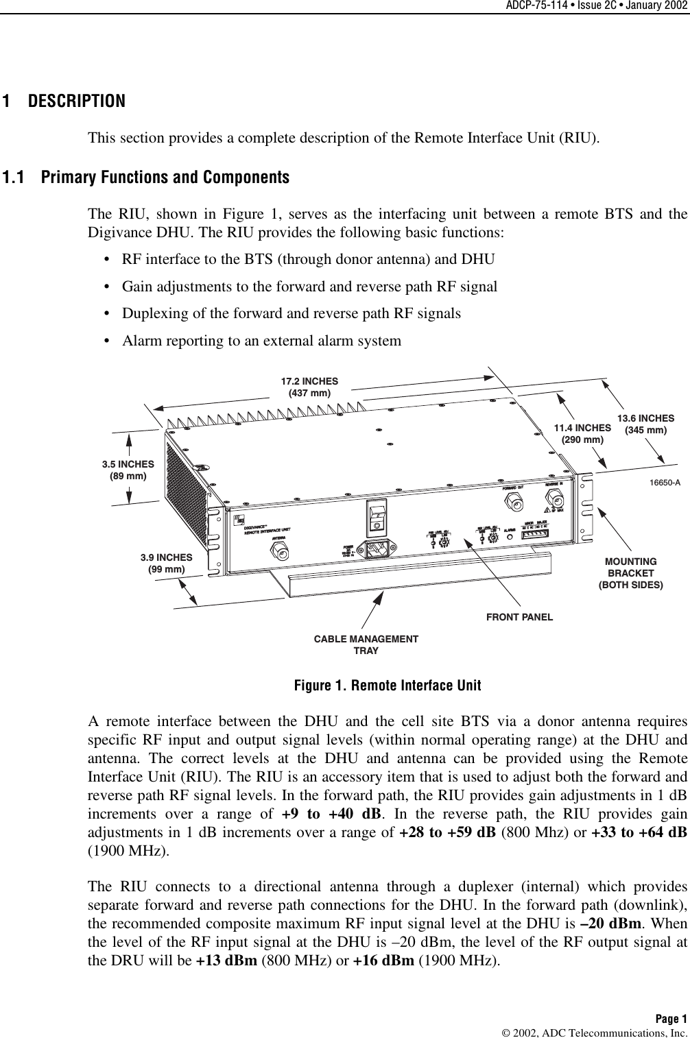
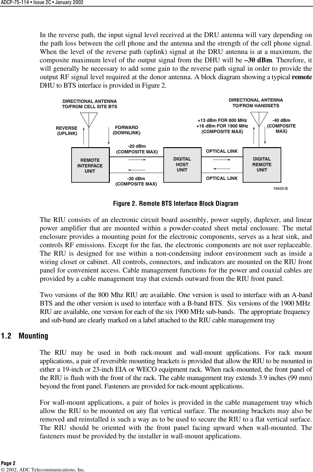
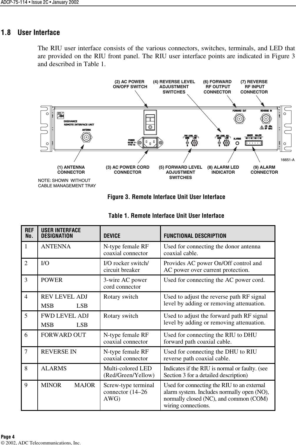
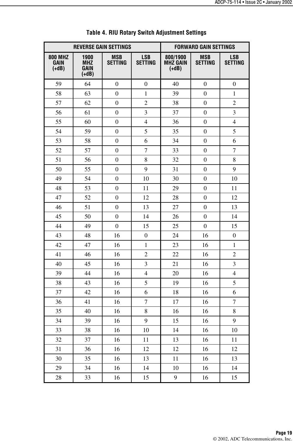
![ADCP-75-114 • Issue 2C • January 2002 Page 18 ©2002, ADC Telecommunications, Inc.Note:An input signal level of –20 dBm at the DHU produces an output signal level of+13 dBm (800 MHz) or +16 dBm (1900 MHz) at the DRU. If maximum output is notrequired at the DRU, the DHU input signal level may be reduced in order to produce alower DRU output signal level. Decreasing the DHU input signal level by 1 dB producesacorresponding 1 dB drop in the DRU output signal level.6. Disconnect the power meter from the forward path cable and reconnect cable to DHU RFIN connector.FWD LEVEL ADJMSB LSB00162468101214REV LEVEL ADJMSB LSB00162468101214INSERT A SMALL SCREWDRIVER INTO THE SLOT.ROTATE THE SWITCH UNTIL THE WHITE ARROW ISALIGNED WITH THE REQUIRED SETTING. 16649-AFigure 14. Rotary Switch Adjustment 3.4 Reverse Path Level Adjustment The level of the composite RF signal that should be input to the antenna will vary dependingon the maximum acceptable DRU path loss per the system design. Typically, the designobjective is for the Digivance system to provide aunity gain. Use the following procedure toadjust the RIU to provide the required reverse path signal level at the antenna:1. Determine the maximum acceptable DRU path loss per the system design specifications.2. Determine the total cable loss that is imposed by the reverse path coaxial cable that linksthe DHU to the RIU, the coaxial cable that links the RIU to the antenna, and any otherdevices (splitters, connectors, etc.) that will impose aloss on the signal.3. Determine the total gain provided by the DRU antenna and the donor antenna.4. Calculate the total gain that must be added by the RIU using the following formula:Reverse Path RIU Gain = [ System Insertion Loss +Designed Path Loss] –[Systemgain (10 dB at 800 MHz, 14 dB at 1900 MHz) +Antenna Gain]The result should be negative which indicates that gain is required.5. Using asmall screwdriver, adjust the REV LEVEL ADJ rotary switches to insert thegain required as determined in step 4. Refer to Figure 14 for adescription of how therotary switches work and to Table 4 for the adjustment settings.Note:The RIU provides areverse path signal adjustment range of from +28 dB to +59 dB(for 800 MHz) and +33 dB to +64 dB (for 1900 MHz).](https://usermanual.wiki/ADC-Telecommunications/DVICSRIU1900/User-Guide-234041-Page-25.png)