ADC Telecommunications DVICSRIU1900 1900 MHz Remote Interface Unit User Manual 75114 cv
ADC Telecommunications Inc 1900 MHz Remote Interface Unit 75114 cv
manual
ADCP-75-114
Issue 2C
January 2002
1188201 Rev A
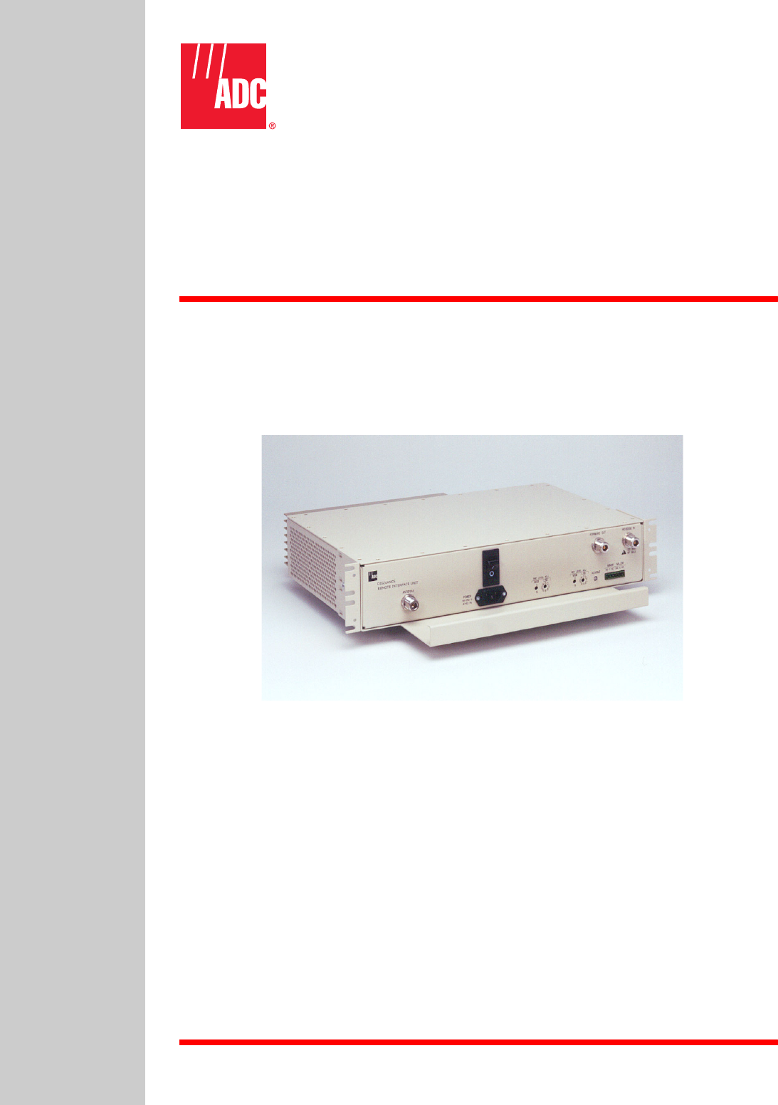
Digivance™ Indoor Coverage Solution
Single Band Remote Interface Unit
(800 or 1900 MHz) User Manual
DRAFT

ADCP-75-114
Issue 2C
January 2002
Digivance™ Indoor Coverage Solution
Single Band Remote Interface Unit
(800 and 1900 MHz) User Manual
1188201 Rev A

ADCP-75-114 • Issue 2C • January 2002 • Preface
Page ii
COPYRIGHT
2002, ADC Telecommunications, Inc.
All Rights Reserved
Printed in the U.S.A.
REVISION HISTORY
ISSUE DATE REASON FOR CHANGE
Issue 106/2001 Original
Issue 207/2001 Deleted forward path OIP3 specification from Table 2, Remote Interface Unit Specifications.
Issue 2C 01/02 Updated to include specifications for 1900 MHz unit.
TRADEMARK INFORMATION
ADC is aregistered trademark of ADC Telecommunications, Inc.
Digivance is atrademark of ADC Telecommunications, Inc.
TORX is aregistered trademark of Textron, Inc.
DISCLAIMER OF LIABILITY
Contents herein are current as of the date of publication. ADC reserves the right to change the contents without prior notice.In no
event shall ADC be liable for any damages resulting from loss of data, loss of use, or loss of profits and ADC further
disclaims any and all liability for indirect, incidental, special, consequential or other similar damages. This disclaimer of
liability applies to all products, publications and services during and after the warranty period.
This publication may be verified at any time by contacting ADC’s Technical Assistance Center at 1-800-366-3891, extension
73475 (in U.S.A. or Canada) or 952-917-3475 (outside U.S.A. and Canada), or by e-mail to technical@adc.com.
ADC Telecommunications, Inc.
P.O. Box 1101, Minneapolis, Minnesota 55440-1101
In U.S.A. and Canada: 1-800-366-3891
Outside U.S.A. and Canada: (952) 938-8080
Fax: (952) 917-1717

ADCP-75-114 • Issue 2C • January 2002 • Preface
Page iii
2002, ADC Telecommunications, Inc.
TABLE OF CONTENTS
Content Page
ABOUT THIS MANUAL........................................................................v
RELATED PUBLICATIONS .....................................................................v
ADMONISHMENTS ..........................................................................v
GENERAL SAFETY PRECAUTIONS ............................................................... vi
STANDARDS CERTIFICATION .................................................................. vi
LIST OF ACRONYMS AND ABBREVIATIONS ......................................................... vi
1 DESCRIPTION ....................................................................... 1
1.1 Primary Functions and Components .................................................. 1
1.2 Mounting .................................................................... 2
1.3 Fault Detection and Alarm Reporting .................................................. 3
1.4 RF Signal Connections ........................................................... 3
1.5 RF Signal Level Adjustments ....................................................... 3
1.6 Powering .................................................................... 3
1.7 Cooling ..................................................................... 3
1.8 User Interface ................................................................. 4
1.9 Specifications ................................................................. 5
2 INSTALLATION ...................................................................... 6
2.1 Tools and Materials ............................................................. 6
2.2 Unpacking and Inspection ......................................................... 7
2.3 Mounting Procedure ............................................................. 7
2.4 Chassis Ground Connection ........................................................ 11
2.5 Coaxial Cable Connections ........................................................11
2.6 External Alarm System Connections ..................................................13
2.7 AC Power Connection ............................................................ 15
3 OPERATION ........................................................................ 16
3.1 Tools and Materials ............................................................. 16
3.2 Turn-Up Unit and Verify Operation.................................................... 16
3.3 Forward Path Level Adjustment ..................................................... 17
3.4 Reverse Path Level Adjustment ..................................................... 18
4 MAINTENANCE ......................................................................20
4.1 Tools and Materials ............................................................. 20
4.2 Fault Detection and Alarm Reporting .................................................. 20
4.3 Fan Replacement...............................................................21
5 CUSTOMER INFORMATION AND ASSISTANCE .................................................. 24

ADCP-75-114 • Issue 2C • January 2002 • Preface
Page iv
2002, ADC Telecommunications, Inc.
This page intentionally blank

ADCP-75-114 • Issue 2C • January 2002 • Preface
Page v
2002, ADC Telecommunications, Inc.
ABOUT THIS MANUAL
This publication provides adescription of the Digivance ICS Remote Interface Unit (RIU)
plus instructions for installing the RIU. An overview of the Digivance ICS and acomplete
description of the Digital Host Unit (DHU), Digital Remote Unit (DRU) and the Digital
Expansion Unit (DEU) are provided in the Digivance ICS System Installation and Operation
Manual (See Related Publications section). The RIU is an interface device that is used in
conjunction with the Digivance ICS product.
RELATED PUBLICATIONS
The following lists related manuals and their publication numbers. Copies of these
publications can be ordered by contacting the ADC Technical Assistance Center at 1-800-366-
3891, extension 73475 (in U.S.A. or Canada) or 952-917-3475 (outside U.S.A. and Canada).
Title/Description ADCP Number
Digivance ICS 800 and 1900 Mhz Systems Installation and
Operation Manual (systems without modular optical transceivers) ADCP-75-110
Digivance ICS 800 MHz Single or Multi-Mode Fiber System Installation
and Operation Manual (systems with modular optical transceivers) ADCP-75-130
Digivance ICS Digital Expansion Unit Installation Instructions ADCP-75-111
Digivance ICS Digital Remote Unit Installation Instructions ADCP-75-112
Digivance ICS Local Interface Unit User Manual ADCP-75-113
ADMONISHMENTS
Important safety admonishments are used throughout this manual to warn of possible hazards
to persons or equipment. An admonishment identifies apossible hazard and then explains
what may happen if the hazard is not avoided. The admonishments —in the form of Dangers,
Warnings, and Cautions —must be followed at all times. These warnings are flagged by use
of the triangular alert icon (seen below), and are listed in descending order of severity of injury
or damage and likelihood of occurrence.
Danger:Danger is used to indicate the presence of a hazard that will cause severe personal
injury, death, or substantial property damage if the hazard is not avoided.
Warning:Warning is used to indicate the presence of a hazard that can cause severe
personal injury, death, or substantial property damage if the hazard is not avoided.
Caution:Caution is used to indicate the presence of a hazard that will or can cause minor
personal injury or property damage if the hazard is not avoided.

ADCP-75-114 • Issue 2C • January 2002 • Preface
Page vi
2002, ADC Telecommunications, Inc.
GENERAL SAFETY PRECAUTIONS
Warning:Wet conditions increase the potential for receiving an electrical shock when
installing or using electrically powered equipment. To prevent electrical shock, never install
or use electrical equipment in awet location or during alightning storm.
STANDARDS CERTIFICATION
FCC:ThisequipmentcomplieswiththeapplicablesectionsofTitle47 CFRParts 22 and 24.
UL/CUL:This equipment complies with UL and CUL 1950 Standard for Safety for
Information Technology Equipment, including Electrical Business Equipment.
IC (Industry Canada):This equipment complies with IC Certification RSS-131.
LIST OF ACRONYMS AND ABBREVIATIONS
The acronyms and abbreviations used in this manual are detailed in the following list:
AAmperes
AC Alternating Current
CUL Canadian Underwriters Laboratories
DC Direct Current
DEU Digital Expansion Unit
DHU Digital Host Unit
DRU Digital Remote Unit
EIA Electronic Industries Association
ESD Electrostatic Discharge
FCC Federal Communications Commission
IC Industry Canada
ICS Indoor Coverage Solution
LIU Local Interface Unit
NOC Network Operations Center
RIU Remote Interface Unit
RF Radio Frequency
UL Underwriters Laboratories
VVolts
VAC Volts Alternating Current
VDC Volts Direct Current
WECO Western Electric Company
ADCP-75-114 • Issue 2C • January 2002
Page 1
©2002, ADC Telecommunications, Inc.
1 DESCRIPTION
This section provides acomplete description of the Remote Interface Unit (RIU).
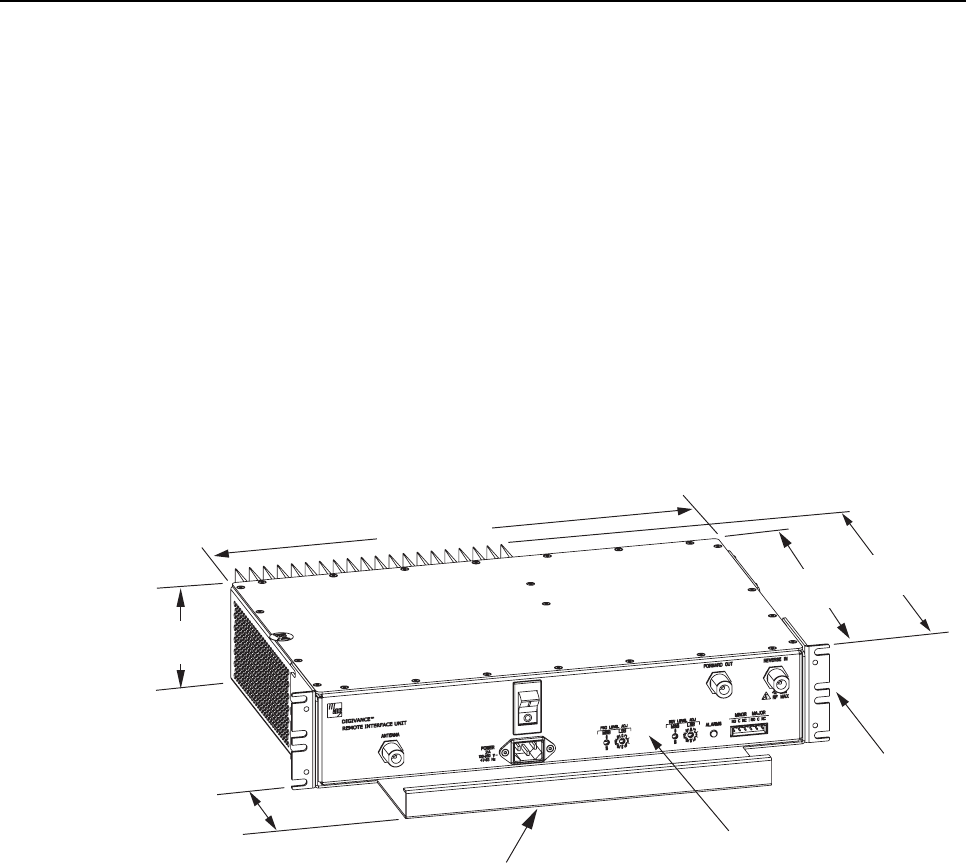
1.1 Primary Functions and Components
The RIU, shown in Figure 1, serves as the interfacing unit between aremote BTS and the
Digivance DHU. The RIU provides the following basic functions:
•RF interface to the BTS (through donor antenna) and DHU
•Gain adjustments to the forward and reverse path RF signal
•Duplexing of the forward and reverse path RF signals
•Alarm reporting to an external alarm system
16650-A
FRONT PANEL
CABLE MANAGEMENT
TRAY
MOUNTING
BRACKET
(BOTH SIDES)
3.5 INCHES
(89 mm)
11.4 INCHES
(290 mm)
3.9 INCHES
(99 mm)
17.2 INCHES
(437 mm)
13.6 INCHES
(345 mm)
Figure 1. Remote Interface Unit
Aremote interface between the DHU and the cell site BTS via a donor antenna requires
specific RF input and output signal levels (within normal operating range) at the DHU and
antenna. The correct levels at the DHU and antenna can be provided using the Remote
Interface Unit (RIU). The RIU is an accessory item that is used to adjust both the forward and
reverse path RF signal levels. In the forward path, the RIU provides gain adjustments in 1 dB
increments over a range of +9 to +40 dB.In the reverse path, the RIU provides gain
adjustments in 1 dB increments over a range of +28 to +59 dB (800 Mhz) or +33 to +64 dB
(1900 MHz).
The RIU connects to adirectional antenna through aduplexer (internal) which provides
separate forward and reverse path connections for the DHU. In the forward path (downlink),
the recommended composite maximum RF input signal level at the DHU is –20 dBm.When
the level of the RF input signal at the DHU is –20 dBm, the level of the RF output signal at
the DRU will be +13 dBm (800 MHz) or +16 dBm (1900 MHz).
ADCP-75-114 • Issue 2C • January 2002
Page 2
©2002, ADC Telecommunications, Inc.
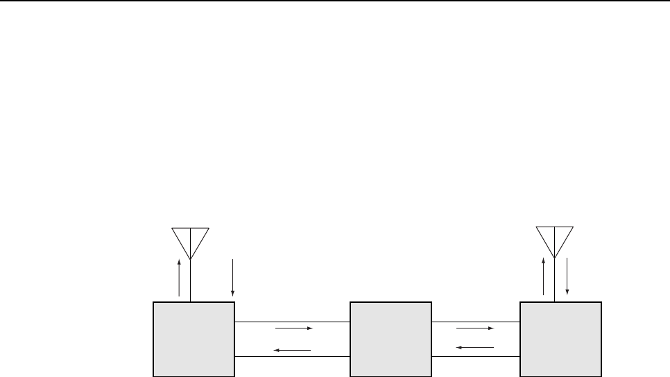
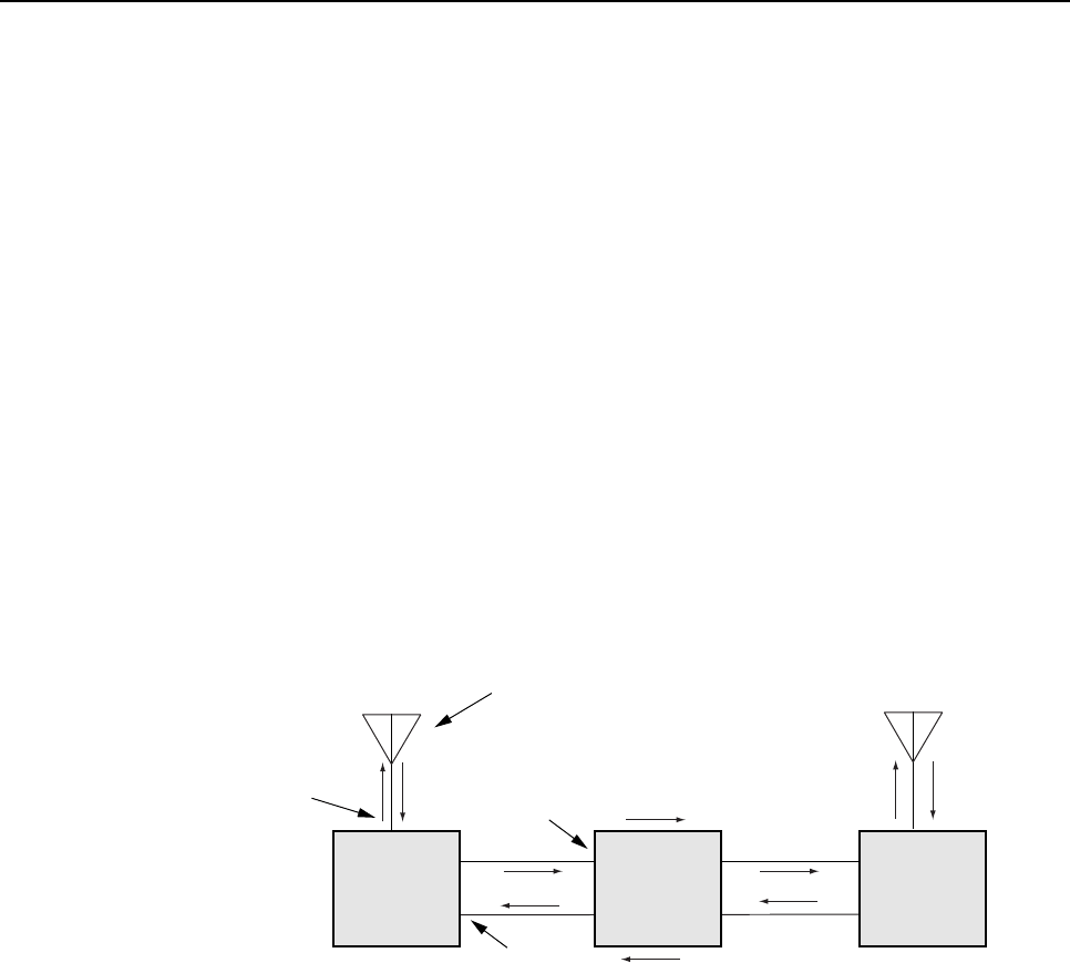
In the reverse path, the input signal level received at the DRU antenna will vary depending on
the path loss between the cell phone and the antenna and the strength of the cell phone signal.
When the level of the reverse path (uplink) signal at the DRU antenna is at amaximum, the
composite maximum level of the output signal from the DHU will be –30 dBm.Therefore, it
will generally be necessary to add some gain to the reverse path signal in order to provide the
output RF signal level required at the donor antenna. Ablock diagram showing atypical remote
DHU to BTS interface is provided in Figure 2.
DIRECTIONAL ANTENNA
TO/FROM CELL SITE BTS
16425-B
REMOTE
INTERFACE
UNIT
FORWARD
(DOWNLINK)
REVERSE
(UPLINK)
-40 dBm
(COMPOSITE
MAX)
-20 dBm
(COMPOSITE MAX)
-30 dBm
(COMPOSITE MAX)
DIGITAL
HOST
UNIT
OPTICAL LINK
OPTICAL LINK
DIGITAL
REMOTE
UNIT
DIRECTIONAL ANTENNA
TO/FROM HANDSETS
+13 dBm FOR 800 MHz
+16 dBm FOR 1900 MHz
(COMPOSITE MAX)
Figure 2. Remote BTS Interface Block Diagram
The RIU consists of an electronic circuit board assembly, power supply, duplexer, and linear
power amplifier that are mounted within apowder-coated sheet metal enclosure. The metal
enclosure provides amounting point for the electronic components, serves as aheat sink, and
controls RF emissions. Except for the fan, the electronic components are not user replaceable.
The RIU is designed for use within anon-condensing indoor environment such as inside a
wiring closet or cabinet. All controls, connectors, and indicators are mounted on the RIU front
panel for convenient access. Cable management functions for the power and coaxial cables are
provided by a cable management tray that extends outward from the RIU front panel.
Two versions of the 800 Mhz RIU are available. One version is used to interface with an A-band
BTSandtheotherversion isusedtointerfacewithaB-band BTS. Six versionsofthe1900 MHz
RIUare available,oneversion foreachofthesix 1900 MHzsub-bands. Theappropriatefrequency
andsub-band are clearlymarkedon alabelattachedtotheRIUcablemanagementtray
1.2 Mounting
The RIU may be used in both rack-mount and wall-mount applications. For rack mount
applications, apair of reversible mounting brackets is provided that allow the RIU to be mounted in
either a19-inch or 23-inch EIA or WECO equipment rack. When rack-mounted, the front panel of
the RIU is flush with the front of the rack. The cable management tray extends 3.9 inches (99 mm)
beyond the front panel. Fasteners are provided for rack-mount applications.
For wall-mount applications, apair of holes is provided in the cable management tray which
allow the RIU to be mounted on any flat vertical surface. The mounting brackets may also be
removed and reinstalled is such away as to be used to secure the RIU to aflat vertical surface.
The RIU should be oriented with the front panel facing upward when wall-mounted. The
fasteners must be provided by the installer in wall-mount applications.

ADCP-75-114 • Issue 2C • January 2002
Page 3
©2002, ADC Telecommunications, Inc.
1.3 Fault Detection and Alarm Reporting
The RIU is designed to detect apower amplifier over or under current condition and ahigh
temperature condition. Asingle front panel Light Emitting Diode (LED) indicator turns from
green to red or yellow if afault is detected. Aset of alarm contacts (normally open and
normally closed) are also provided for reporting an alarm to an external alarm system when a
fault is detected. Both major alarm (power amplifier over/undercurrent condition or power
failure) and minor alarm (high temperature) contacts are provided.
1.4 RF Signal Connections
The RF signal connections between the RIU and DHU are supported through apair of type N
female connectors mounted on the RIU front panel. One connector is used for connecting the
forward path coaxial cable and the other connector is used for connecting the reverse path coaxial
cable. The RF signal connection between the RIU and the donor antenna is supported through a
single type Nfemale connector. The single connector is used for connecting the coaxial jumper
cable that links the RIU to the donor antenna. The DHU cannot be connected directly to adonor
antenna and requires an interface device such as the RIU.
1.5 RF Signal Level Adjustments
The RIU is equipped with two digital attenuators for adjusting the signal levels of the forward
and reverse path RF signals. The attenuators provide an attenuation adjustment range of 0 to
31 dB and can be set in 1 dB increments. In the forward path,this range provides a
maximum gain of +40 dB (attenuator set to 0) or a minimum gain of +9 dB (attenuator set to
31 dB). In the reverse path for 800 MHz units, this range provides amaximum gain of +59
dB (attenuator set to 0) or a minimum gain of +28 dB (attenuator set to 31 dB). In the reverse
path for 1900 MHz units, this range provides amaximum gain of +64 dB (attenuator set to 0)
or a minimum gain of +33 dB (with attenuator set to 31 dB).
Each attenuator is adjustable by means of two rotary switches which are mounted behind the
RIU front panel. Access to each rotary switch is through asmall hole. Asmall screwdriver is
required to adjust the switch setting. Turning each switch adds or removes attenuation and
therefore adjusts the signal level of the specified signal path.
1.6 Powering
The RIU is powered by 120/240 VAC (50–60 Hz) power which is supplied through astandard
three-conductor AC power cord. The power cord is provided with the RIU and is 98 inches
(2.5 meters )long. Aresetable circuit breaker/On-Off switch is provided at the unit front
panel. The switch applies power to the RIU internal power supply.
1.7 Cooling
Continuous air flow for cooling is provided by a fan mounted on the right side of the housing.
Aminimum of 3 inches (76 mm) of clearance space must be provided on both the left and
right sides of the RIU for air intake and exhaust. An alarm is provided that indicates if ahigh
temperature condition (>58º C/136º F) occurs. The fan may be field-replaced if it fails.
ADCP-75-114 • Issue 2C • January 2002
Page 4
©2002, ADC Telecommunications, Inc.
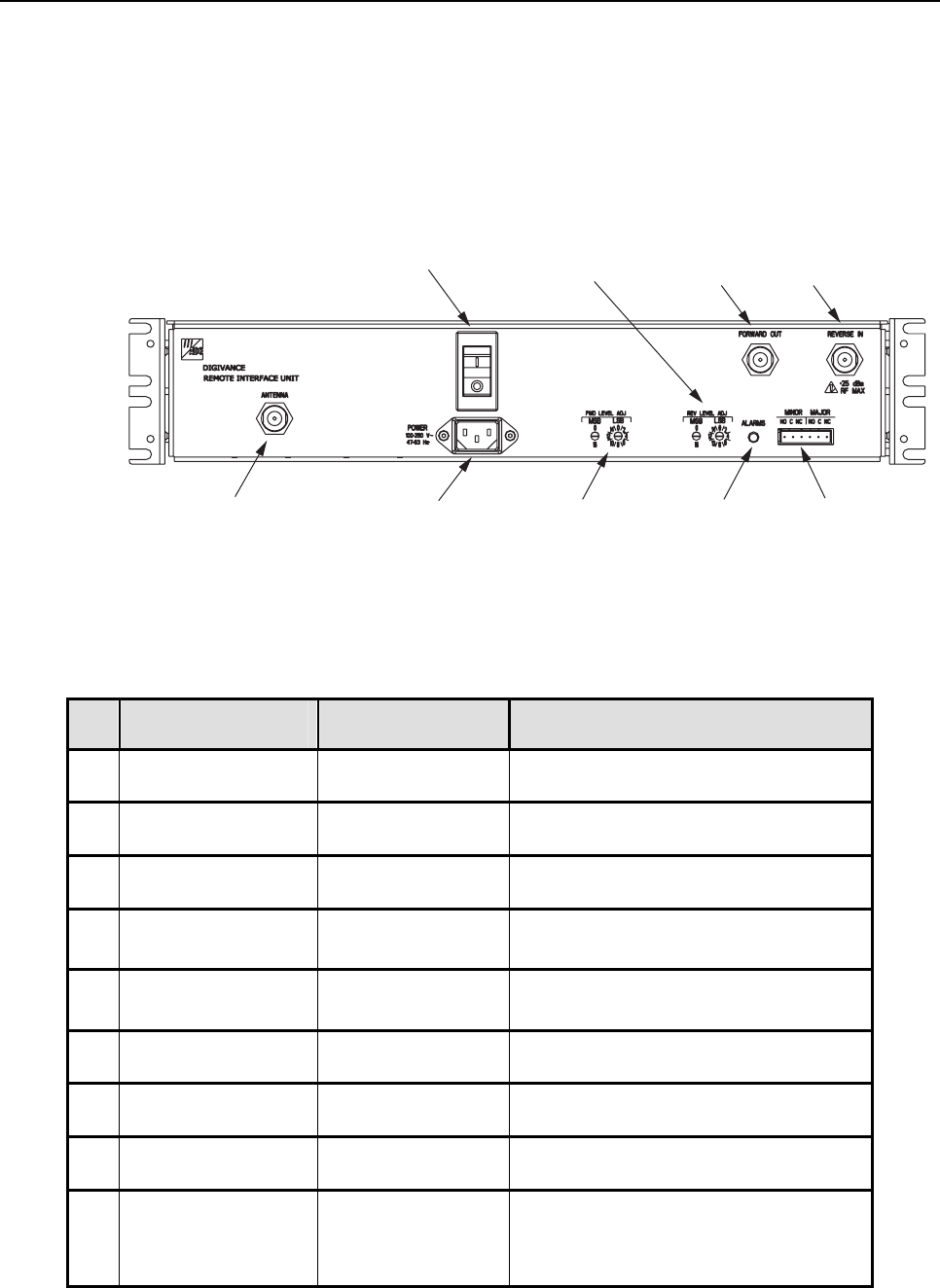
1.8 User Interface
The RIU user interface consists of the various connectors, switches, terminals, and LED that
are provided on the RIU front panel. The RIU user interface points are indicated in Figure 3
and described in Table 1.
NOTE: SHOWN WITHOUT
CABLE MANAGEMENT TRAY
(3) AC POWER CORD
CONNECTOR
(8) ALARM LED
INDICATOR
(9) ALARM
CONNECTOR
(1) ANTENNA
CONNECTOR
(5) FORWARD LEVEL
ADJUSTMENT
SWITCHES
(2) AC POWER
ON/OFF SWITCH
(6) FORWARD
RF OUTPUT
CONNECTOR
(7) REVERSE
RF INPUT
CONNECTOR
(4) REVERSE LEVEL
ADJUSTMENT
SWITCHES
16651-A
Figure 3. Remote Interface Unit User Interface
Table 1. Remote Interface Unit User Interface
REF
No.
USER INTERFACE
DESIGNATION
DEVICE
FUNCTIONAL DESCRIPTION
1ANTENNA N-type female RF
coaxial connector Used for connecting the donor antenna
coaxial cable.
2I/O I/O rocker switch/
circuit breaker Provides AC power On/Off control and
AC power over current protection.
3POWER 3-wire AC power
cord connector Used for connecting the AC power cord.
4REV LEVEL ADJ
MSB LSB
Rotary switch Used to adjust the reverse path RF signal
level by adding or removing attenuation.
5FWD LEVEL ADJ
MSB LSB
Rotary switch Used to adjust the forward path RF signal
level by adding or removing attenuation.
6FORWARD OUT N-type female RF
coaxial connector Used for connecting the RIU to DHU
forward path coaxial cable.
7REVERSE IN N-type female RF
coaxial connector Used for connecting the DHU to RIU
reverse path coaxial cable.
8ALARMS Multi-colored LED
(Red/Green/Yellow) Indicates if the RIU is normal or faulty. (see
Section 3for adetailed description)
9MINOR MAJOR Screw-type terminal
connector (14–26
AWG)
Used for connecting the RIU to an external
alarm system. Includes normally open (NO),
normally closed (NC), and common (COM)
wiring connections.

ADCP-75-114 • Issue 2C • January 2002
Page 5
©2002, ADC Telecommunications, Inc.
1.9 Specifications
The specifications for the RIU are provided in Table 2. All specifications apply after afive
minute warm-up period.
Table 2. Remote Interface Unit Specifications
PARAMETER SPECIFICATION REMARKS
Environmental
Operating Temperature 0º to 50º C (32º to 122º F)
Storage Temperature –30º to +70º C (–22 to 158º F)
Humidity No condensation
Weather resistance Indoor installation only
RF Forward Path
800 MHz unit 869 to 894 MHz
1900 MHz unit 1930 to 1990 MHz
RF Gain +9 to +40 dB Adjustable in 1 dB steps
Gain Variation ± 1.5 dB Over frequency, temperature,
and unit-to-unit.
Gain stepsize accuracy ±(0.2 + 3% of gain setting in dB)
dB
Output power –20 dBm composite maximum to
Digivance ICS input With proper input signal and
attenuation setting
Input level –29 dBm composite maximum To drive Digivance ICS DHU
VSWR 1.5:1 or better, both ports
RF Reverse Path
800 MHz unit 824 to 849 MHz
1900 MHz unit 1850 to 1910 MHz
RF Gain
800 MHz
1900 MHz +28 to +59 dB
+33 to +64 dB Adjustable in 1 dB steps
Gain Variation
800 MHz
1900 MHz ±1.5 dB
±3 dB Over frequency, temperature,
and unit-to-unit.
Gain stepsize accuracy ±(0.2 + 3% of gain setting in dB)
dB
Output power
800 MHz
1900 MHz +29 dBmcompositemaximum
+34 dBm composite maximum When driven with Digivance
ICS DHU
Input level
(Recommended
composite maximum)
–30 dBm FromDigivanceICSDHU
output
VSWR 1.5:1 or better, both ports
OIP3 ≥+46 dBm
(continued)

ADCP-75-114 • Issue 2C • January 2002
Page 6
©2002, ADC Telecommunications, Inc.
Table 2. Remote Interface Unit Specifications, continued
PARAMETER SPECIFICATION REMARKS
Physical
Weight 20.2 lbs (8.7 kg)
Dimensions (H×W×D) 3.5 ×17.2 ×17.25 Inches
(89 ×437 ×438 mm) Dimension for width does not
include the mounting brackets
Color Putty white
RF connections Type N Female
Alarm connection Screw terminals (14–26 AWG) NO, NC, and COM
Reliability MTBF 80,000 hours
Electrical
Power source 120–240 VAC, 50–60 Hz
AC Connection IEC 320 Male
Power consumption 250 W Maximum
Current rating 85–250 VAC, 2Amp input
Donor Antenna
Type Directional
Output 1000 watts composite maximum
2 INSTALLATION
This section provides the installation procedures for the RIU. Installation of the various
Digivance ICS units may proceed separately from the installation of the RIU.
2.1 Tools and Materials
The following tools are required in order to complete the procedures in this section:
•Box cutter
•Pencil or scribe
•Medium and small size flat-bladed screwdrivers
•Phillips screwdriver (#2)
•TORX screwdriver (T20)
•Wire cutters
•Wire stripper
•Tool kit for attaching N-type male connectors to coaxial cable
•Drill and assorted drill bits (wall-mount installations only)

ADCP-75-114 • Issue 2C • January 2002
Page 7
©2002, ADC Telecommunications, Inc.
The following materials are required in order to complete the procedures in this section:
•Wall-mount fasteners (wall-mount applications only)
• #22 AWG (0.40 mm) category 3 or 5 cable (for external alarm connections)
• #18 AWG (1.00 mm) insulated stranded copper wire (for chassis grounding wire)
•Ring terminal for #18 wire (for chassis ground wire connection)
•High performance, flexible, low loss 50-ohm coaxial cable
•N-type male connectors
•Wire ties
2.2 Unpacking and Inspection
This sub-section provides instructions for opening the shipping boxes, verifying that all parts
have been received, and verifying that no shipping damage has occurred. Use the following
procedure to unpack and inspect the RIU:
1. Open the shipping carton and carefully unpack the RIU from the protective packing
material.
2. Check the RIU for broken or missing parts. If there are any damages, contact ADC (see
Section 5at the end of this manual) for an RMA (Return Material Authorization) and to
reorder if replacement is required.
2.3 Mounting Procedure
The RIU may be either rack-mounted or wall-mounted. Of the procedures that follow, use
whichever procedure is appropriate for the installation.
2.3.1 Rack-Mount Installation
The RIU may be mounted in either a19-inch or 23-inch EIA or WECO equipment rack. Both
US standard and metric machine screws are included for rack mounting the RIU. When
loading the RIU in arack, make sure the mechanical loading of the rack is even to avoid a
hazardous condition such as aseverely unbalanced rack. The rack should safely support the
combined weight of all the equipment it holds. In addition, the maximum recommended
ambient temperature for the RIU is 50º C (122º F). Allow sufficient air circulation or space
between units when the RIU is installed in amulti-unit rack assembly because the operating
ambient temperature of the rack environment might be greater than room ambient.
Warning:Wet conditions increase the potential for receiving an electrical shock when
installing or using electrically-powered equipment. To prevent electrical shock, never install
or use electrical equipment in awet location or during alightning storm.
Use the following procedure to install the RIU in the equipment rack:
1. The RIU is shipped with the mounting brackets installed for 19-inch rack installations. If
mounting the RIU in a19-inch rack, proceed to step 4. If mounting the RIU in a23-inch
rack, proceed to step 2.
ADCP-75-114 • Issue 2C • January 2002
Page 8
©2002, ADC Telecommunications, Inc.
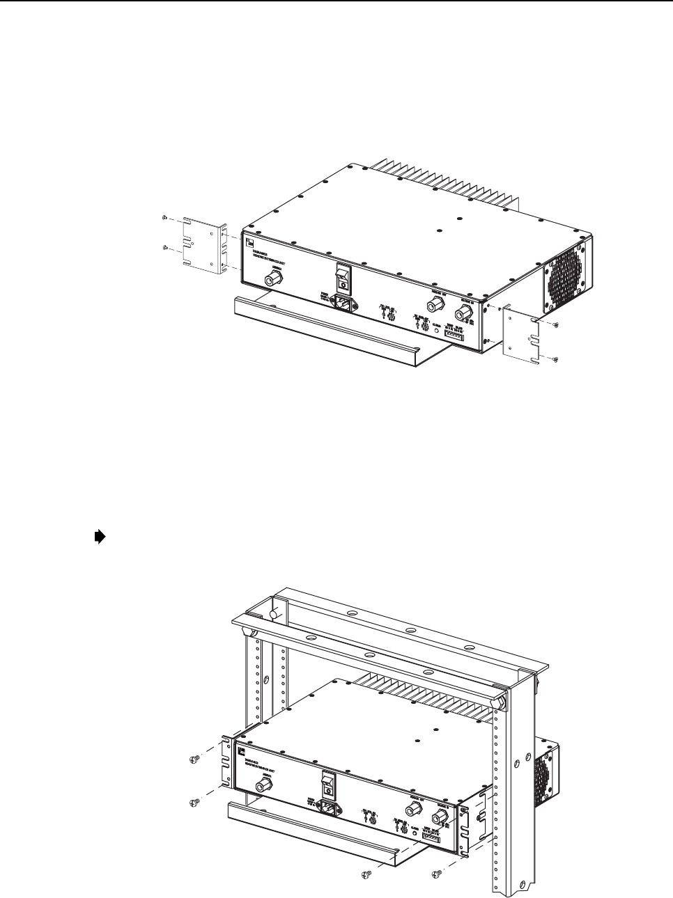
2. Remove both mounting brackets from the RIU (requires TORX screwdriver with T20 bit).
3. Reinstall both mounting brackets so the long side of the bracket is flush with the RIU
front panel as shown in Figure 4. Use the screws removed in step 2to re-attach the
brackets to the RIU enclosure.
16487-B
REMOVE AND REINSTALL MOUNTING
BRACKETS AS SHOWN FOR
INSTALLATION IN 23-INCH RACKS
Figure 4. Installing the Mounting Brackets for 23-Inch Rack Installations
4. Position the RIU in the designated mounting space in the rack (per system design) and
then secure the mounting brackets to the rack using the four machine screws provided
(use #12-24 screws or M6 x10screws, whichever is appropriate) as shown in Figure 5.
Note:Provide aminimum of 3 inches (76 mm) of clearance space on both the left and
right sides of the RIU for air intake and exhaust.
16483-B
Figure 5. RIU Rack Mount Installation
ADCP-75-114 • Issue 2C • January 2002
Page 9
©2002, ADC Telecommunications, Inc.
2.3.2 Wall-Mount Installation
The RIU may be mounted from any flat vertical surface. It is recommended that abacker
board such as 3/4-inch plywood be applied over the mounting surface to provide asecure base
for attaching the RIU. Two mounting holes are provided in the cable management tray for
securing the RIU to the mounting surface. In addition, the mounting brackets may be removed
and then reinstalled in such away that they can be used for securing the RIU to the mounting
surface. Either method for mounting may be used at the discretion of the installer. The
fasteners must be provided by the installer. Use the following procedure to wall-mount the
RIU:
Warning:Wet conditions increase the potential for receiving an electrical shock when
installing or using electrically-powered equipment. To prevent electrical shock, never install
or use electrical equipment in awet location or during alightning storm.
1. Obtain the appropriate fasteners (lag bolts, screw anchors, etc.) for securing the RIU to
the mounting surface.
2. If the mounting brackets will be used to secure the RIU to the mounting surface, proceed
to step 3. If the mounting brackets will not be used to secure the RIU to the mounting
surface, skip steps 3and 4and proceed to step 5.
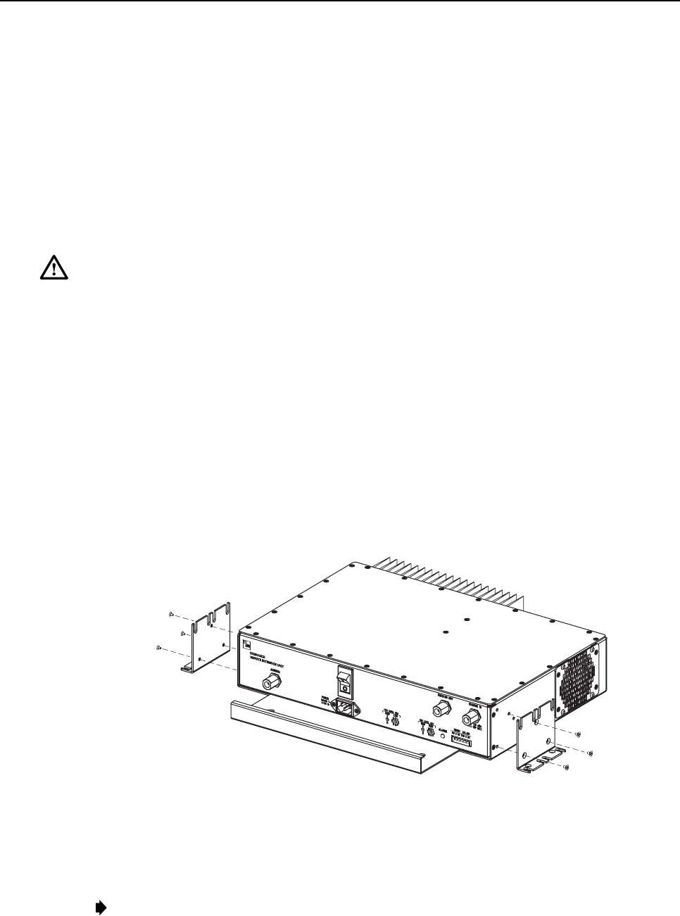
3. Remove both mounting brackets from the RIU (requires TORX screwdriver with T20
bit).
4. Reinstall both mounting brackets so the short side of the bracket is flush with the bottom
of the RIU as shown in Figure 6. Use the screws removed in step 3to re-attach the
brackets to the RIU enclosure.
16484-B
Figure 6. Installing the Mounting Brackets for Wall-Mount Installation
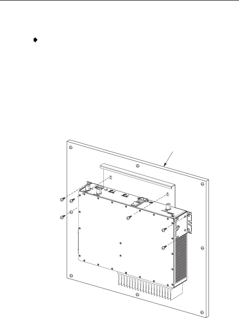
5. Position the RIU on the mounting surface in the specified location (per the system
design) with the front panel facing up as shown in Figure 7.
Note:Provide aminimum of 3 inches (76 mm) of clearance space on both the left and
right sides of the RIU for air intake and exhaust.
ADCP-75-114 • Issue 2C • January 2002
Page 10
©2002, ADC Telecommunications, Inc.
6. Using the RIU as atemplate, mark the location of the mounting holes on the mounting
surface.
Note: The mounting holes in the RIU cable management tray are spaced 11-21/32 inches
(296 mm) center to center.
7. Set the RIU aside and then drill appropriately sized holes in the mounting surface for the
fasteners.
8. If using only the mounting brackets to secure the RIU to the mounting surface, skip step
9and proceed to step 10. If using the cable management tray mounting holes to secure
the RIU to the mounting surface, proceed to step 9.
9. Partially install the fasteners for the cable management tray mounting holes. Leave the
head of each fastener protruding about 1/4 inch (6 mm) from the mounting surface.
10. Hang the RIU from the fasteners installed in step 9 or position the RIU for installation if
using only the mounting brackets.
11. Install and securely tighten all fasteners.
16486-B
BACKER BOARD SUCH
AS 3/4-INCH PLYWOOD
Figure 7. RIU Wall-Mount Installation
ADCP-75-114 • Issue 2C • January 2002
Page 11
©2002, ADC Telecommunications, Inc.
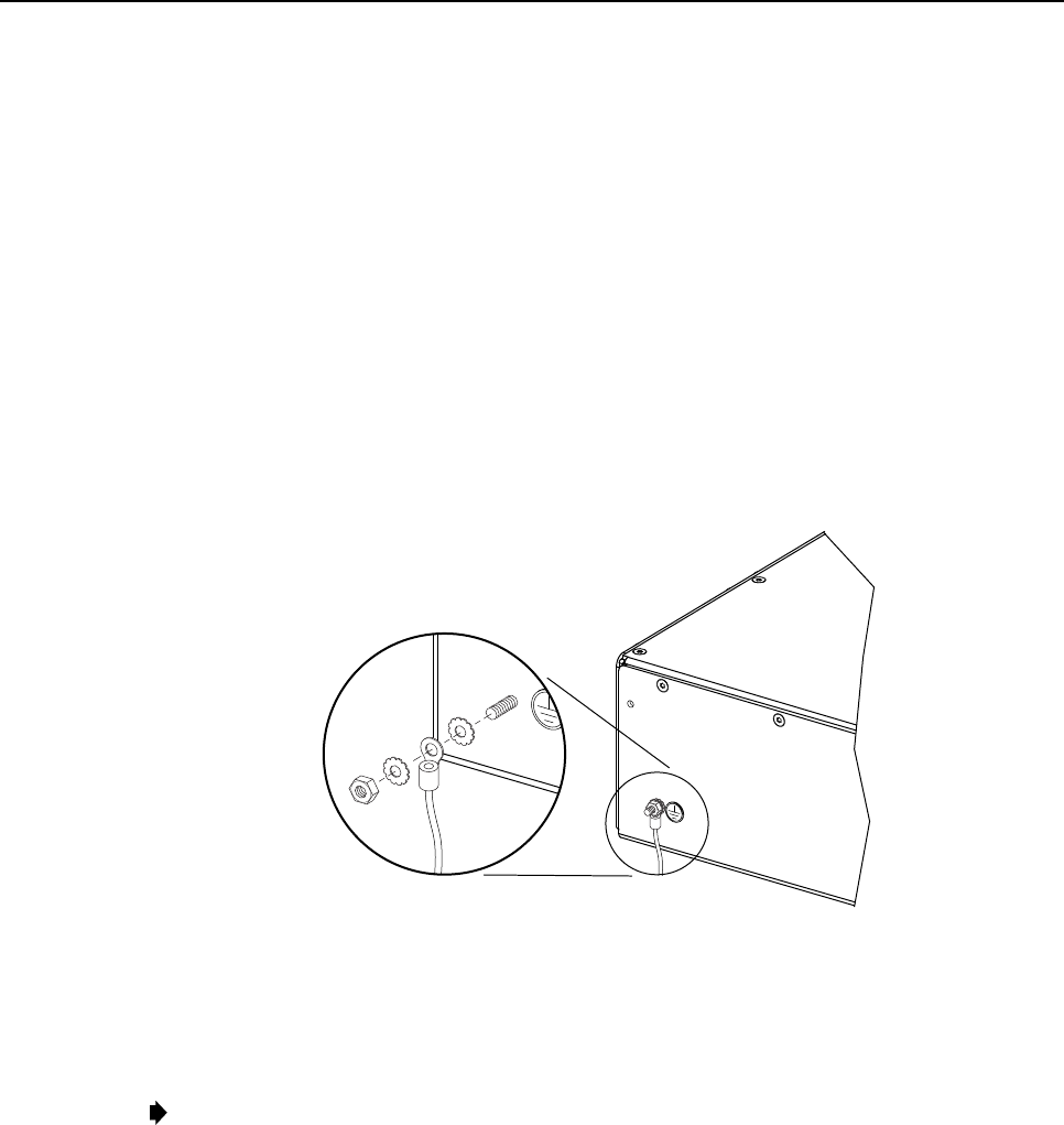
2.4 Chassis Ground Connection
Astud is provided on the rear side of the chassis for connecting agrounding wire to the
chassis. Use the following procedure to connect the grounding wire to the chassis and to route
the grounding wire to an approved earth ground source:
1. Obtain alength of #18 AWG (1.00 mm) insulated stranded copper wire for use as a
chassis grounding wire.
2. Terminate one end of the wire with aring terminal.
3. Locate the chassis ground stud at the rear of the RIU as shown in Figure 8.
4. Attach the ring end of the wire to the chassis ground stud (see Figure 8).
5. Route the free end of the chassis grounding wire to an approved (per local code or
practice) earth ground source.
16169-A
Figure 8. Chassis Ground Stud
6. Cut the chassis grounding wire to length and connect it to the approved ground source as
required by local code or practice.
Note:Be sure to maintain reliable grounding for rack and wall mounted equipment. Pay
particular attention to ground source connections.
2.5 Coaxial Cable Connections
The RF signal connections between the RIU and DHU are supported through apair of type N
female connectors mounted on the RIU front panel. One connector is used for connecting the
forward path coaxial cable and the other connector is used for connecting the reverse path
coaxial cable. The RF signal connection between the RIU and the donor antenna is supported
through asingle type Nfemale connector. The single connector is used for connecting the
coaxial jumper cable that links the RIU to the donor antenna.
ADCP-75-114 • Issue 2C • January 2002
Page 12
©2002, ADC Telecommunications, Inc.
2.5.1 Forward and Reverse Path Coaxial Cable Connections
Use the following procedure to install the forward and reverse path coaxial cables that link the
RIU to the DHU:
1. Locate the forward and reverse path coaxial cables that were routed to the RIU from the
DHU.
Note:The procedures for routing the reverse and forward path coaxial cables from the
DHU to the RIU and for connecting the cables to the DHU are covered in the Digivance
ICS System Installation and Operation Manual (See Related Publications section) which
is provided with the DHU.
2. Terminate each cable with atype Nmale connector following the connector supplier’s
recommendations.
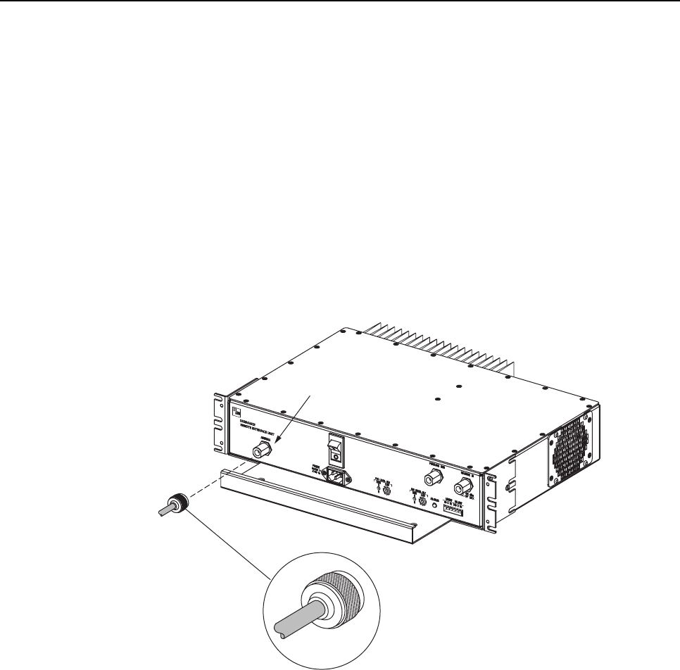
3. Connect the forward path cable to the FORWARD OUT connector on the RIU front
panel as shown in Figure 9.
16652-A
FORWARD OUT
CONNECTOR
REVERSE IN
CONNECTOR
TYPE-N MALE CONNECTOR
Figure 9. FORWARD OUT and REVERSE IN Coaxial Cable Connections
4. Connect the reverse path cable to the REVERSE IN connector on the RIU front panel as
shown in Figure 9.
5. Dress and secure cables at the RIU.
2.5.2 Antenna Coaxial Cable Connection
Use the following procedure to install the coaxial cable that links the RIU to the donor
antenna:
Note:To comply with Maximum Permissible Exposure (MPE) requirements, the maximum
composite output from the antenna cannot exceed 1000 watts EIRP and the antenna must be
permanently installed in a fixed location that provides at least 6meters (20 feet) of separation
from all persons.
ADCP-75-114 • Issue 2C • January 2002
Page 13
©2002, ADC Telecommunications, Inc.
1. Obtain the required length of high performance, flexible, low loss 50-ohm coaxial
communications cable for the antenna coaxial connection.
2. Route the coaxial cable between the RIU and the donor antenna (per system design) and
cut to the required length. Allow sufficient slack for dressing and organizing cables at the
RIU and antenna.
3. Terminate each cable end with atype Nmale connector following the connector
supplier’s recommendations.
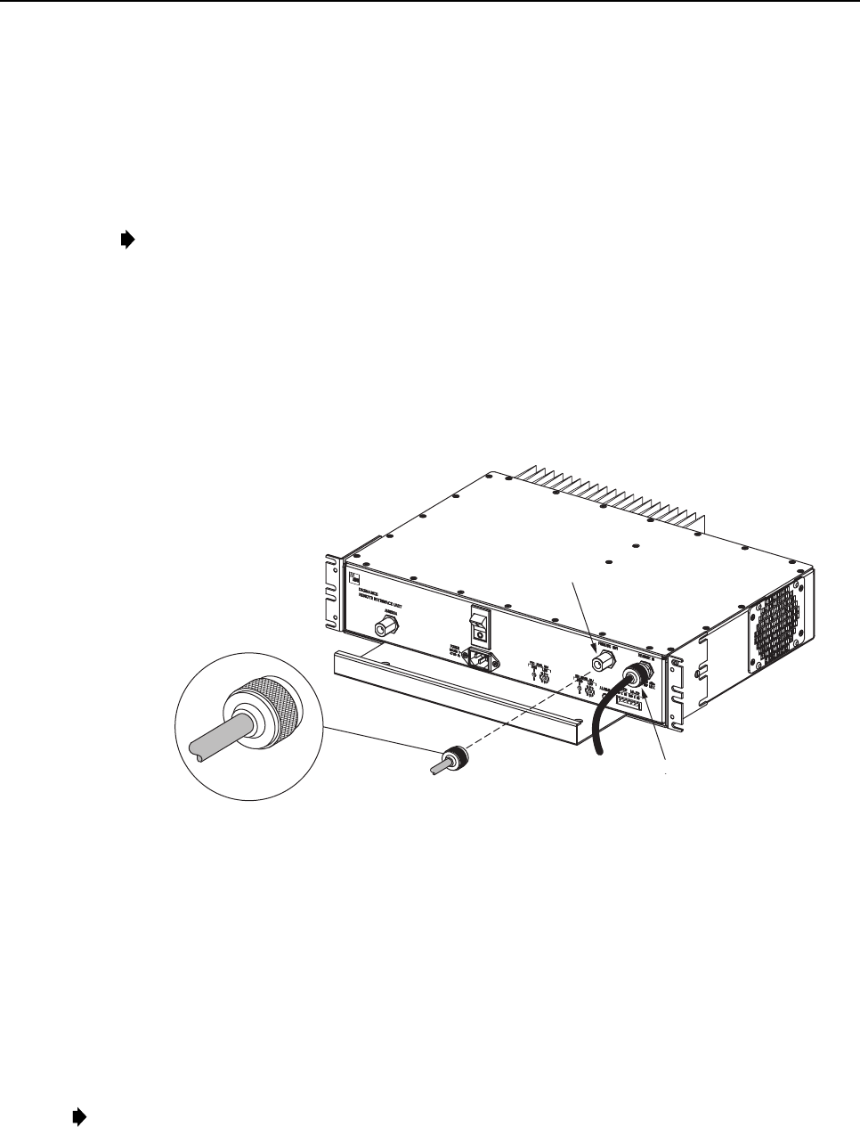
4. Connect the RIU end of the antenna cable to the ANTENNA connector on the RIU front
panel as shown in Figure 10.
5. Connect the antenna end of the antenna cable to the donor antenna.
6. Dress and secure cables at the RIU and donor antenna.
16653-A
ANTENNA
CONNECTOR
TYPE-N MALE CONNECTOR
Figure 10. RIU Antenna Cable Connection
2.6 External Alarm System Connections
The alarm interface between the RIU and an external alarm system is supported by a six-
terminal plug (with screw-type terminals) that connects to areceptacle on the RIU front panel.
The terminal plug provides connections to normally open (NO) and normally closed (NC) dry
type alarm contacts for both minor and major alarms. Acategory 3 or 5 cable is typically used
to connect the RIU to the external alarm system. Use the following procedure to install the
alarm wiring and connect it to the RIU:
ADCP-75-114 • Issue 2C • January 2002
Page 14
©2002, ADC Telecommunications, Inc.
1. Obtain the required length of category 5cable.
2. Route the cable between the RIU and the external alarm system (if not already routed)
and then cut to required length. Allow sufficient slack for dressing and organizing the
cable at the RIU.
3. Strip back the outer cable sheath and insulation to expose the wires at both ends of the
cable and strip back 0.2 inches (5 mm) of insulation each wire.
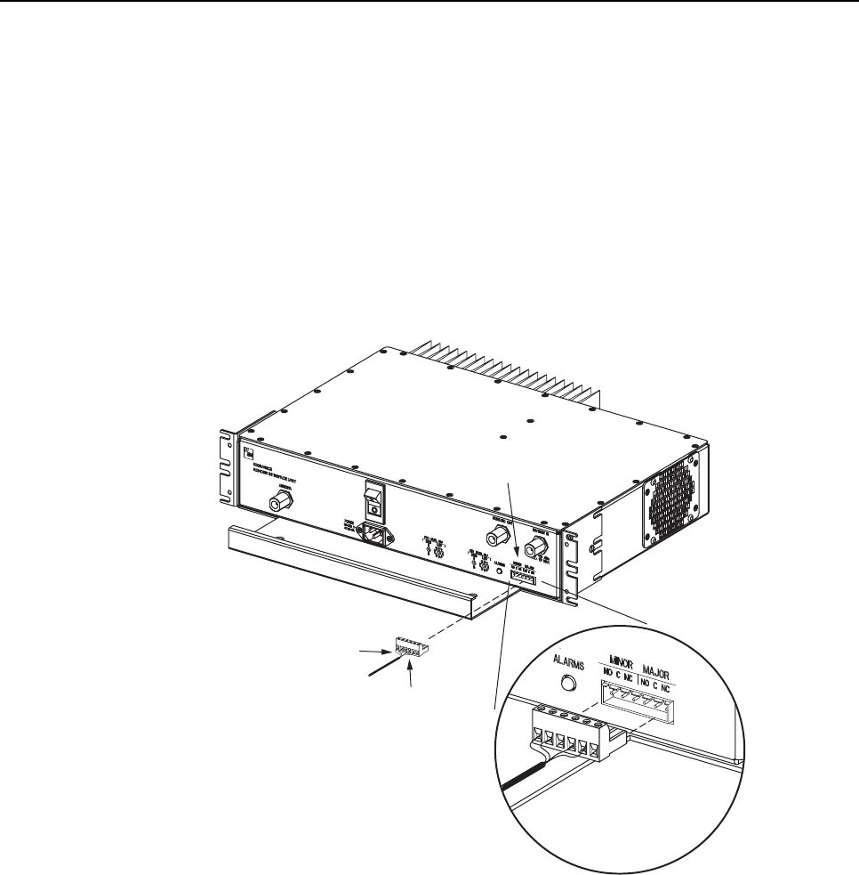
4. Connect the Major alarm wire pair to the MAJOR COM/NC or MAJOR COM/NO
terminals (whichever is required by the external alarm system) on the RIU alarm terminal
connector (supplied with RIU) as shown in Figure 11.
16482-B
ALARM
CONNECTOR
MAJOR
ALARM
WIRES
MINOR
ALARM
WIRES
ALARM CONNECTOR
DETAIL
Figure 11. External Alarm System Connections
5. Connect the Minor alarm wire pair to the MINOR COM/NC or MINOR COM/NO
terminals (whichever is required by the external alarm system) on the RIU alarm terminal
connector as shown in Figure 11.
6. Connect the Major and Minor alarm wire pairs to the appropriate terminals on the
external alarm system.
7. Dress and secure cable.
ADCP-75-114 • Issue 2C • January 2002
Page 15
©2002, ADC Telecommunications, Inc.
2.7 AC Power Connection
The AC power interface between the RIU and the AC power source is supported by a 3-wire
AC power cord connector located on the RIU front panel. The AC connector provides a
connection point for the power cord which is provided separately with the RIU. Use the
following procedure to install the AC power cord:
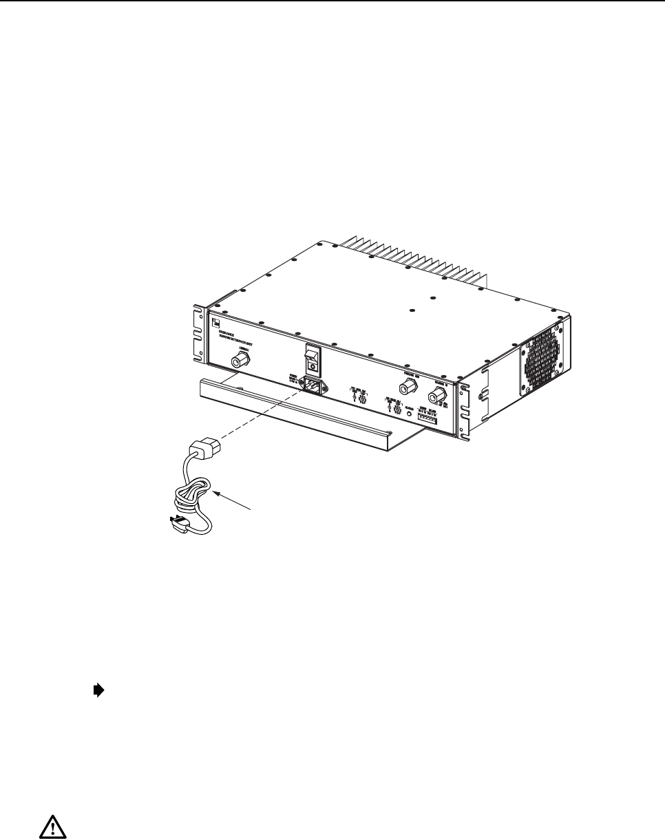
1. Place the RIU AC power ON/OFF switch, shown in Figure 12, in the OFF position
(press O).
16654-A
AC POWER CORD
Figure 12. AC Power Connection
2. Locate the AC power cord which is provided separately with the RIU. Use only the AC
power cord provided with the RIU or an equivalent UL listed and CSA certified 3-
conductor, 18 AWG cord terminated in amolded-on plug cap rated 125 V, 15 A with a
minimum length of 6 feet (1.8 m).
Note:The RIU is intended to be used with a 3-wire grounding type plug which has a
grounding pin. Equipment grounding is to ensure safe operation. Do not defeat the
grounding means. Verify RIU is reliably grounded when installed.
3. Connect the receptacle end of the power cord to the AC connector on the RIU.
4. Route the plug end of the power cord to the specified AC outlet (per the system design)
and connect plug to outlet.
Warning:The current rating of the RIU is 2Amps at 120 VAC. Avoid overloading circuits
which may cause damage to over-current protection devices and supply wiring.
5. Dress and secure cable.
6. When the RIU installation is complete, refer to Section 3 of this manual for the unit turn-
up and test procedures.

ADCP-75-114 • Issue 2C • January 2002
Page 16
©2002, ADC Telecommunications, Inc.
3 OPERATION
This section provides guidelines for turning-up the RIU, verifying that the RIU is operating
properly, setting the forward and reverse path signal levels, and correcting any installation
problems.
3.1 Tools and Materials
The following tools and materials are required in order to complete the procedures in this
section:
•RF power meter
•Pencil or pen
•Writing pad
3.2 Turn-Up Unit and Verify Operation
The process of turning-up the RIU and verifying operation involves setting the forward and
reverse path signal levels, turning on the power, verifying that the LED indicator shows
normal operation, and then measuring the forward and reverse path signal levels. Refer to
Table 3 for adetailed description of the ALARM LED indicator.
Table 3. Remote Interface Unit LED Indicator
INDICATOR COLOR DESCRIPTION
ALARM
Green
Yellow
Red
Off
Indicates if the RIU is normal or if afault is detected.
RIU in normal state, no faults detected.
High temperature fault detected. (Minor alarm)
Over or undercurrent fault on power amplifier detected. (Major alarm)
AC power off or RIU internal fault.
Use the following procedure to power-up the system:
1. Temporarily disconnect the alarm system or notify the alarm system provider that unit
turn-up is in progress.
2. Adjust the forward and reverse path signal levels as specified in Sections 3.3 and 3.4.
3. Verify that the donor antenna is properly installed and connected.
Note:To comply with Maximum Permissible Exposure (MPE) requirements, the
maximum composite output from the antenna cannot exceed 1000 watts EIRP and the
antenna must be permanently installed in a fixed location that provides at least 6meters
(20 feet) of separation from all persons.
4. Verify that the RIU is connected to the appropriate AC outlet.
5. Place the ON/OFF switch on the RIU in the ON position (press I).
6. Verify that the ALARM LED on the RIU turns green.
ADCP-75-114 • Issue 2C • January 2002
Page 17
©2002, ADC Telecommunications, Inc.
7. Check the forward path RF signal level at the DHU RF IN port and verify that the DHU
composite input signal level is –20 dBm (provides maximum DRU output). Re-adjust
FWD LEVEL ADJ rotary switches to add or remove gain if required.
8. Check the reverse path RF signal level at the antenna and verify that the signal level is
correct per the system design. Re-adjust REV LEVEL ADJ rotary switches to add or
remove gain if required.
9. Reconnect the alarm system or notify the alarm system provider that unit turn-up is complete.
3.3 Forward Path Level Adjustment
The level of the composite RF output signal from the donor antenna will vary depending on
the gain of the antenna, the number of channels present, and the level of the channels. For
maximum output at the DRU, the forward path signal level must be adjusted to provide a–20
dBm composite maximum input signal level at the DHU input port. Use the following
procedure to adjust the RIU to provide the required forward path signal level at the DHU:
1. Connect a power meter to the antenna cable. The required signal levels and test points
are shown in Figure 13.
DIRECTIONAL
ANTENNA TO/FROM
CELL SITE BTS
16655-B
REMOTE
INTERFACE
UNIT
FORWARD
(DOWNLINK)
REVERSE
(UPLINK)
+13 dBm FOR 800 MHz
+16 dBm for 1900 MHz
(COMPOSITE MAX)
-40 dBm
(COMPOSITE
MAX)
DIGITAL
HOST
UNIT
OPTICAL LINK
OPTICAL LINK
DIGITAL
REMOTE
UNIT
DIRECTIONAL ANTENNA
TO/FROM HANDSETS
MEASURE RF LEVEL
OF A SINGLE CARRIER
AT ANTENNA OUTPUT
CHECK SYSTEM DESIGN
SPECIFICATIONS FOR RF LEVEL
REQUIRED AT DONOR ANTENNA
-20 dBm
COMPOSITE MAX
INPUT TO DHU
-30 dBm
(COMPOSITE MAX
INPUT TO RIU)
Figure 13. Signal Levels and Test Points
2. Measure the power level of the composite output signal from the antenna. If the power
level exceeds –29 dBm, use an external attenuator to reduce the signal level until it falls
within the range of –29 to –60 dBm.
3. Subtract –20 (the composite input signal level required at the DHU to maximize the output
signal at the DRU) from the level measured in step 2. The difference equals the amount of
gain required to raise the forward path signal to –20 dBm.
4. Disconnect the power meter from the antenna cable and connect the antenna cable
connector to the RIU.
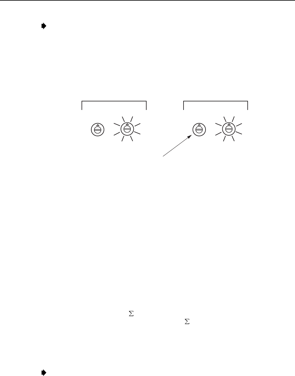
5. Using asmall screwdriver, adjust the FWD LEVEL ADJ rotary switches to insert the
gain required to provide a–20 dBm signal at the DHU. The RIU provides aforward path
signal adjustment range of from +9 dB to +40 dB. Refer to Figure 14 for adescription of
how the rotary switches work and to Table 4 for the adjustment settings.
ADCP-75-114 • Issue 2C • January 2002
Page 18
©2002, ADC Telecommunications, Inc.
Note:An input signal level of –20 dBm at the DHU produces an output signal level of
+13 dBm (800 MHz) or +16 dBm (1900 MHz) at the DRU. If maximum output is not
required at the DRU, the DHU input signal level may be reduced in order to produce a
lower DRU output signal level. Decreasing the DHU input signal level by 1 dB produces
acorresponding 1 dB drop in the DRU output signal level.
6. Disconnect the power meter from the forward path cable and reconnect cable to DHU RF
IN connector.
FWD LEVEL ADJ
MSB LSB
00
16
2
4
6
8
10
12
14
REV LEVEL ADJ
MSB LSB
00
16
2
4
6
8
10
12
14
INSERT A SMALL SCREWDRIVER INTO THE SLOT.
ROTATE THE SWITCH UNTIL THE WHITE ARROW IS
ALIGNED WITH THE REQUIRED SETTING.
16649-A
Figure 14. Rotary Switch Adjustment
3.4 Reverse Path Level Adjustment
The level of the composite RF signal that should be input to the antenna will vary depending
on the maximum acceptable DRU path loss per the system design. Typically, the design
objective is for the Digivance system to provide aunity gain. Use the following procedure to
adjust the RIU to provide the required reverse path signal level at the antenna:
1. Determine the maximum acceptable DRU path loss per the system design specifications.
2. Determine the total cable loss that is imposed by the reverse path coaxial cable that links
the DHU to the RIU, the coaxial cable that links the RIU to the antenna, and any other
devices (splitters, connectors, etc.) that will impose aloss on the signal.
3. Determine the total gain provided by the DRU antenna and the donor antenna.
4. Calculate the total gain that must be added by the RIU using the following formula:
Reverse Path RIU Gain = [ System Insertion Loss +Designed Path Loss] –[System
gain (10 dB at 800 MHz, 14 dB at 1900 MHz) +Antenna Gain]
The result should be negative which indicates that gain is required.
5. Using asmall screwdriver, adjust the REV LEVEL ADJ rotary switches to insert the
gain required as determined in step 4. Refer to Figure 14 for adescription of how the
rotary switches work and to Table 4 for the adjustment settings.
Note:The RIU provides areverse path signal adjustment range of from +28 dB to +59 dB
(for 800 MHz) and +33 dB to +64 dB (for 1900 MHz).

ADCP-75-114 • Issue 2C • January 2002
Page 19
©2002, ADC Telecommunications, Inc.
Table 4. RIU Rotary Switch Adjustment Settings
REVERSE GAIN SETTINGS FORWARD GAIN SETTINGS
800 MHZ
GAIN
(+dB)
1900
MHZ
GAIN
(+dB)
MSB
SETTING
LSB
SETTING
800/1900
MHZ GAIN
(+dB)
MSB
SETTING
LSB
SETTING
59 64 0 0 40 0 0
58 63 0 1 39 0 1
57 62 0 2 38 0 2
56 61 0 3 37 0 3
55 60 0 4 36 0 4
54 59 0 5 35 0 5
53 58 0 6 34 0 6
52 57 0 7 33 0 7
51 56 0 8 32 0 8
50 55 0 9 31 0 9
49 54 0 10 30 0 10
48 53 0 11 29 0 11
47 52 0 12 28 0 12
46 51 0 13 27 0 13
45 50 0 14 26 0 14
44 49 0 15 25 0 15
43 48 16 0 24 16 0
42 47 16 1 23 16 1
41 46 16 2 22 16 2
40 45 16 3 21 16 3
39 44 16 4 20 16 4
38 43 16 5 19 16 5
37 42 16 6 18 16 6
36 41 16 7 17 16 7
35 40 16 8 16 16 8
34 39 16 9 15 16 9
33 38 16 10 14 16 10
32 37 16 11 13 16 11
31 36 16 12 12 16 12
30 35 16 13 11 16 13
29 34 16 14 10 16 14
28 33 16 15 9 16 15

ADCP-75-114 • Issue 2C • January 2002
Page 20
©2002, ADC Telecommunications, Inc.
4 MAINTENANCE
This section explains the alarm reporting system, provides amethod for isolating and
troubleshooting faults, and provides procedures for replacing the cooling fan.
The RIU requires no regular maintenance to insure continuous and satisfactory operation.
Maintenance, as it applies to the RIU, primarily involves diagnosing and correcting service
problems as they occur. When an alarm is reported, it will be necessary to follow asystematic
troubleshooting procedure to locate the problem. Once the source of the problem is isolated,
the appropriate corrective action can be taken to resolve the problem. The only component that
can be replaced is the cooling fan. The failure of any other component within the RIU requires
replacement of the RIU.
4.1 Tools and Materials
The following tools and materials are required in order to complete the procedures in this
section:
•ESD wrist strap
•Small size flat-bladed screwdriver
•TORX screwdriver (T10)
4.2 Fault Detection and Alarm Reporting
Detection of a fault by the RIU generates an external alarm response. An ALARM LED
indicator is provided on the RIU front panel to visually indicate when afault is detected. In
addition, normally open (NO) and normally closed (NC) dry alarm contacts are provided to
report minor and major alarms to an external alarm system. Aminor alarm is defined as a
high temperature condition. Amajor alarm is defined as apower amplifier over/undercurrent
condition.
When the RIU alarm contacts are connected to an external alarm system, detection of a fault
will generate an alarm at the Network Operations Center (NOC). Whenever aproblem is
reported, refer to Table 5 to isolate and correct the fault.
ADCP-75-114 • Issue 2C • January 2002
Page 21
©2002, ADC Telecommunications, Inc.
Table 5. Fault Isolation and Troubleshooting
Alarm Type Minor
ALARM Indicator: Yellow
Problem The RIU is overheating.
POSSIBLE CAUSE CORRECTIVE ACTION/COMMENTS
1. Air intake or exhaust openings to RIU
chassis blocked.
2. Ambient temperature > 58º C/136º F.
3. Faulty fan.
4. Faulty RIU.
1. Remove cause of air-flow blockage.
2. Reduce ambient temperature.
3. Replace fan (see Section 4.3).
4. Replace RIU.
Alarm Type: Major
ALARM Indicator Red:
Problem Over or undercurrent condition detected at power amplifier.
POSSIBLE CAUSE CORRECTIVE ACTION/COMMENTS
1. Faulty RIU. 1. Replace RIU.
Alarm Type Major
ALARM Indicator Off
Problem The RIU is not powered.
POSSIBLE CAUSE CORRECTIVE ACTION/COMMENTS
1. AC power source off or disconnected.
2. Faulty RIU
1. Restore AC power.
2. Replace RIU.
4.3 Fan Replacement
It is recommended that the fan (catalog number DGVI-200000FAN) be replaced every five years.
Replacement of afan requires that the RIU be turned off for ashort period of time. This will drop
all existing calls, cause atemporary loss of service, and generate amajor alarm. Use the following
procedure to replace the RIU cooling fan:
1. Before touching the RIU or handling afan, slip on an Electro-Static Discharge (ESD)
wrist strap and connect the ground wire to an earth ground source. Wear the ESD wrist
strap while completing each section of the fan installation procedure.
Warning:Electronic components can be damaged by static electrical discharge. To prevent
ESD damage, always wear an ESD wrist strap when working on the RIU and when handling
electronic components.
2. Notify the NOC or alarm monitoring system operator that the system is going offline.
3. Place the RIU AC power On/Off switch in the OFF position (press O)and disconnect the
AC power cord.
Caution:High voltage components are present within the RIU enclosure. Disconnect the AC
power cord from the AC power source before proceeding to step 4.
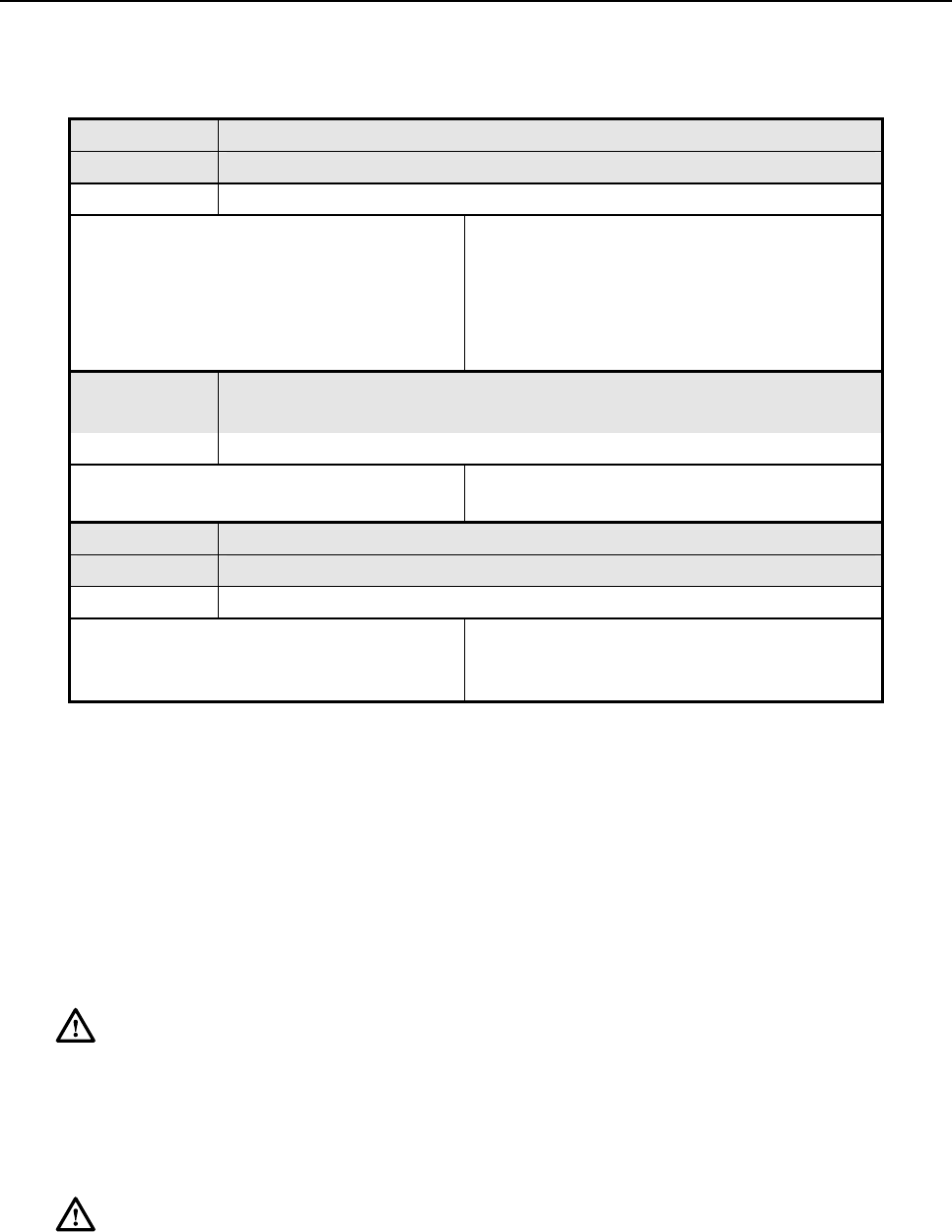
4. Remove the four flat-head screws (requires TORX screwdriver with T15 bit) that secure the
fan/grill assembly to the side of the enclosure as shown in Figure 15 and save for reuse.
ADCP-75-114 • Issue 2C • January 2002
Page 22
©2002, ADC Telecommunications, Inc.
16637-A
LATCH
Figure 15. Fan/Grill Assembly Removal
5. Carefully withdraw the fan/grill assembly from the enclosure until the wiring harness is
exposed and the connector is accessible.
6. Lift the small latch on the wiring harness connector (see Figure 15) and carefully unplug
the connector from the circuit board connector.
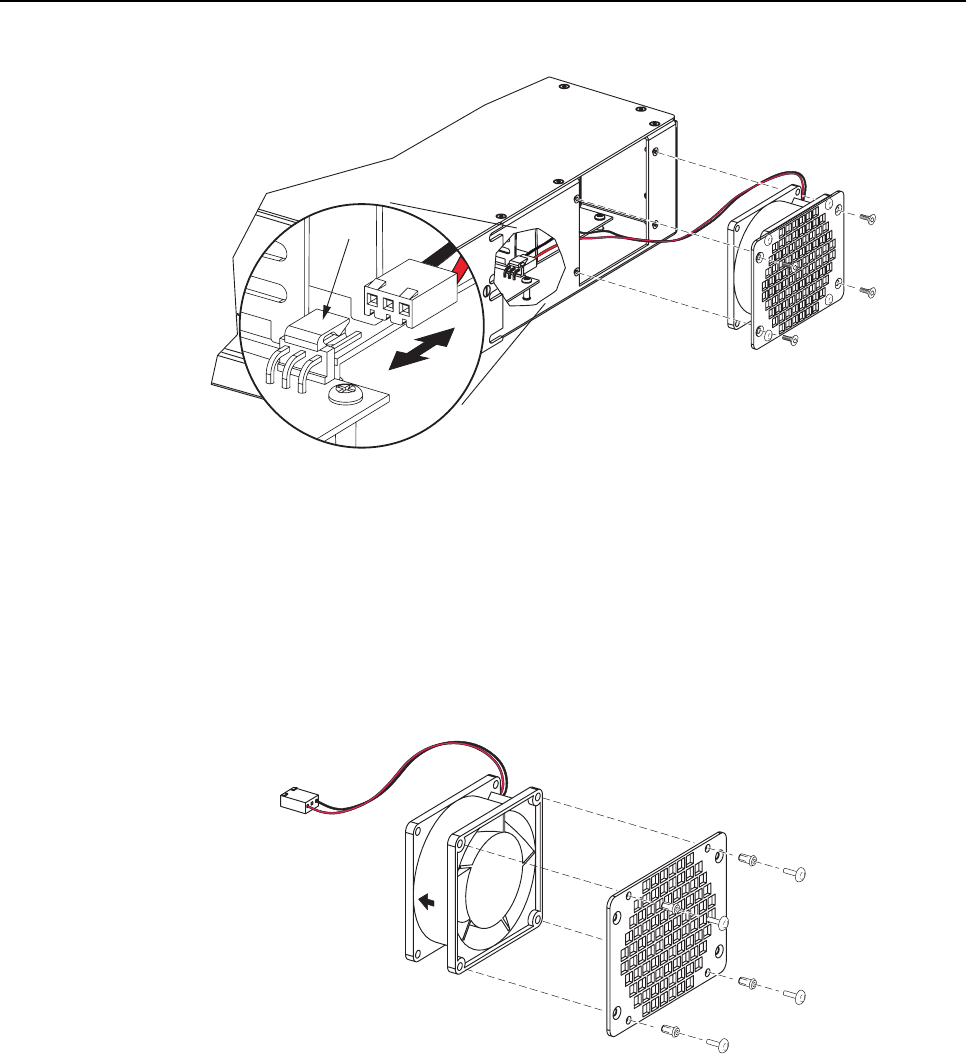
7. Remove the four plastic rivets that secure the faulty fan to the grill by pushing outward
on rivet center post until the rivet can be withdrawn from the grill as shown in Figure 16.
16485-B
Figure 16. Removing Fan From Grill
8. Remove the fan from the grill and then locate the replacement fan.
9. Use the rivets removed in step 7to secure the replacement fan to the grill. Orient the fan
so the wiring harness is on the right side (side of fan that faces toward back of enclosure
when installed) and the arrow on the fan housing faces into the enclosure.
10. Connect the wiring harness connector to the circuit board connectors.
11. Route the wiring harness under the fan.

ADCP-75-114 • Issue 2C • January 2002
Page 23
©2002, ADC Telecommunications, Inc.
12. Secure the fan/grill assembly to the side of the enclosure (see Figure 15) using the four
flat-head screws removed in step 4.
13. Reconnect the AC power cord and place the RIU AC power On/Off switch in the ON
position (press I).
14. Verify that the fan runs properly following power up.
15. Notify the NOC or alarm monitoring system operator that the system is going back online.
ADCP-75-114 • Issue 2C • January 2002
Page 24
5 CUSTOMER INFORMATION AND ASSISTANCE
EUROPE
Sales Administration: +32-2-712-65 00
Technical Assistance: +32-2-712-65 42
U.S.A. OR CANADA
Sales: 1-800-366-3891 Extension 73000
Technical Assistance: 1-800-366-3891 Extension 73475
ELSEWHERE
Sales Administration: +1-952-938-8080
Technical Assistance: +1-952-917-3475
13944-G
WWW.ADC.COM
technical@adc.com
ADC TELECOMMUNICATIONS, INC
PO BOX 1101,
MINNEAPOLIS, MN 55440-1101, USA
U.S.A.
U.S.A.
ADC EUROPEAN CUSTOMER SERVICE, INC
BELGICASTRAAT 2,
1930 ZAVENTEM, BRUSSELS, BELGIUM
PRODUCT INFORMATION AND TECHNICAL ASSISTANCE:
WRITE:
PHONE:
SYSTEM INTEGRATION DIVISION (SID)
+1-952-294-3600
Contents herein are current as of the date of publication. ADC reserves the right to change the contents without prior notice.
In no event shall ADC be liable for any damages resulting from loss of data, loss of use, or loss of profits and ADC further
disclaims any and all liability for indirect, incidental, special, consequential or other similar damages. This disclaimer of
liability applies to all products, publications and services during and after the warranty period. This publication may be
varified at any time by contacting ADC's Technical Assistance Center.
©2002, ADC Telecommunications, Inc.
All Rights Reserved
Printed in U.S.A.

i
www.adc.com