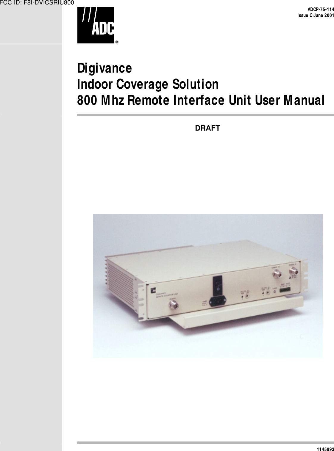
ADC Telecommunications DVICSRIU800 800 MHz Remote Interface Unit User Manual manual

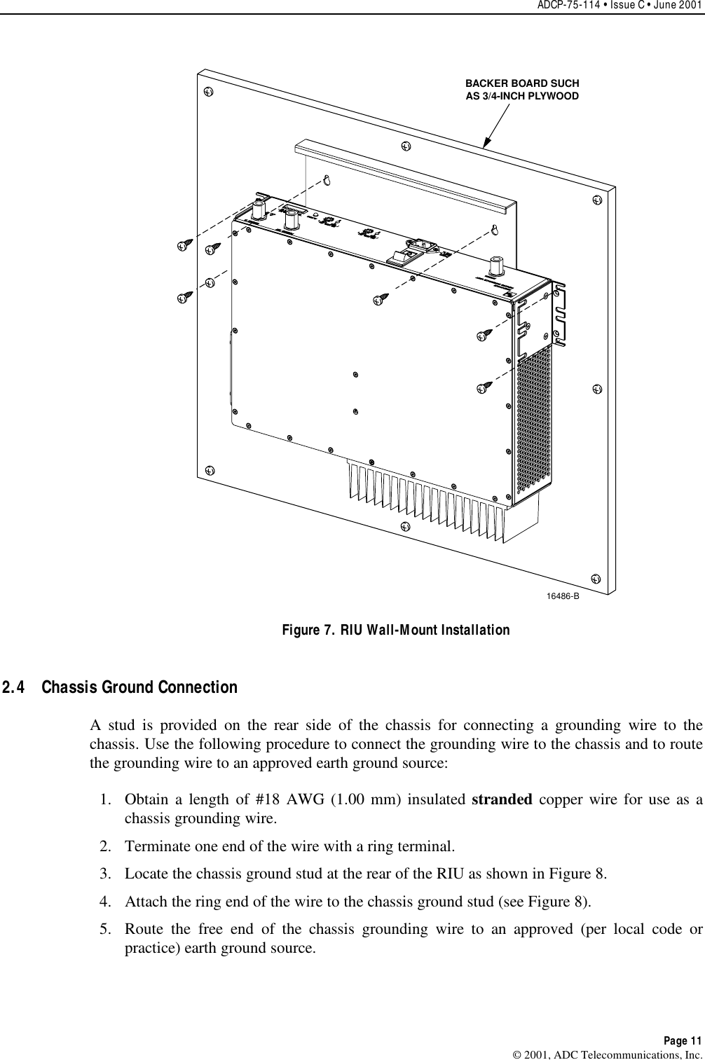
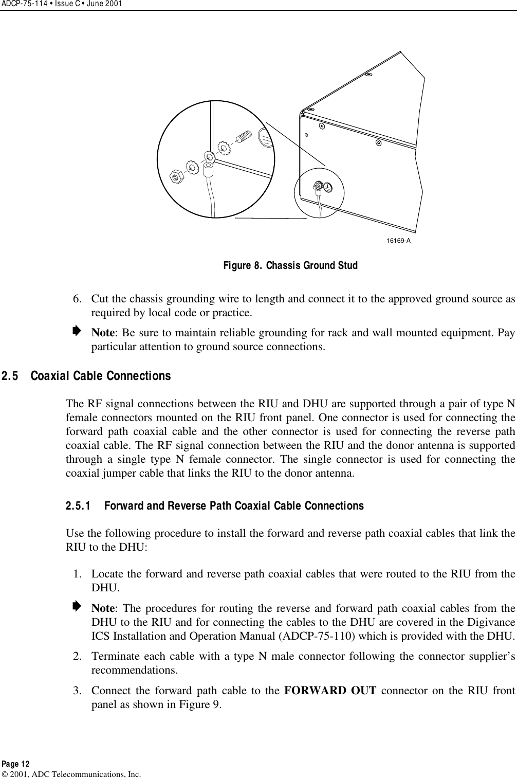
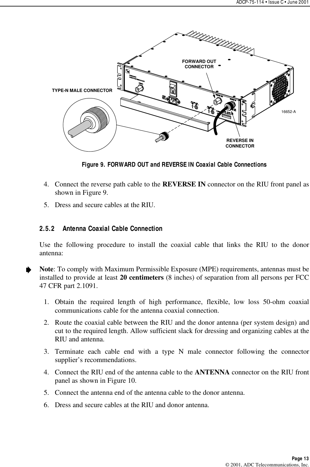
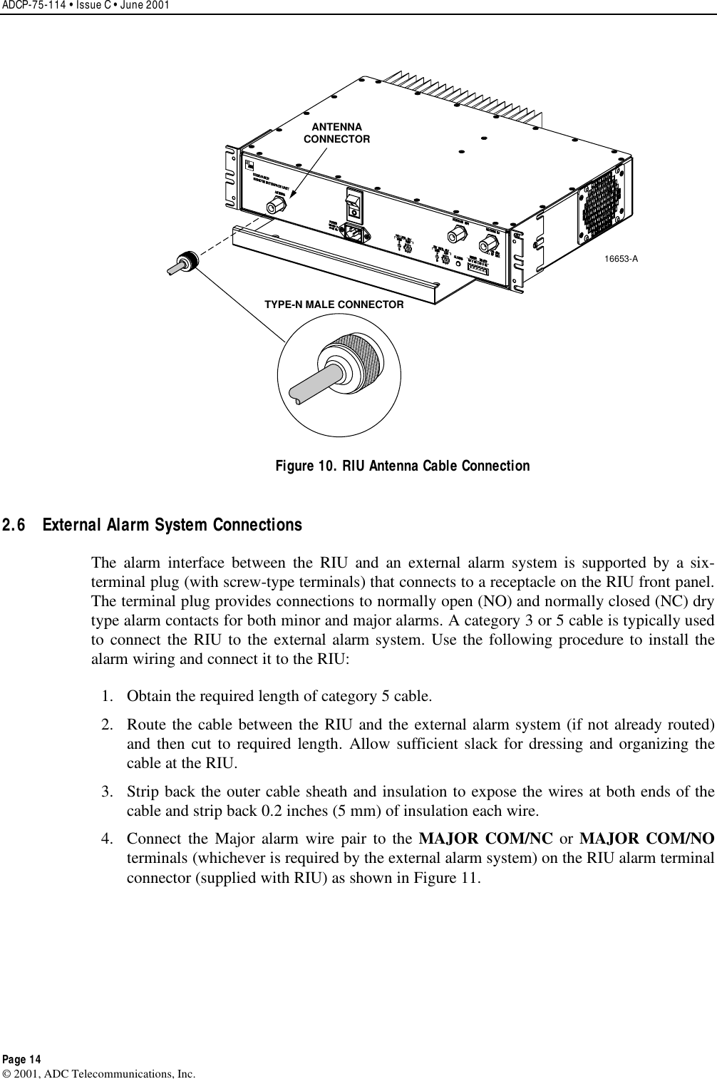
ADC Telecommunications Inc 800 MHz Remote Interface Unit manual

manual

    ADCP-75-114 Issue C June 2001 Digivance Indoor Coverage Solution 800 Mhz Remote Interface Unit User ManualDRAFT1145993 FCC ID: F8I-DVICSRIU800
ADCP-75-114 • Issue C • June 2001 • Preface Page ii COPYRIGHT 2001, ADC Telecommunications, Inc.All Rights ReservedPrinted in the U.S.A.REVISION HISTORY   ISSUE  DATE  REASON FOR CHANGE Issue C06/2001 OriginalTRADEMARK INFORMATION ADC and ADC Telecommunications are registered trademarks of ADC Telecommunications, Inc.Digivance is atrademark of ADC Telecommunications, Inc.TORX is aregistered trademark of Textron, Inc.DISCLAIMER OF LIABILITY Contents herein are current as of the date of publication. ADC reserves the right to change the contents without prior notice.In noevent shall ADC be liable for any damages resulting from loss of data, loss of use, or loss of profits and ADC further disclaimsany and all liability for indirect, incidental, special, consequential or other similar damages.This disclaimer of liability appliesto all products, publications and services during and after the warranty period.This publication may be verified at any time by contacting ADC’s Technical Assistance Center at 1-800-366-3891, extension 63475(in U.S.A. or Canada) or 952-946-3475 (outside U.S.A. and Canada), or by e-mail to bcg_tac@adc.com.ADC Telecommunications, Inc.P.O. Box 1101, Minneapolis, Minnesota 55440-1101In U.S.A. and Canada: 1-800-366-3891Outside U.S.A. and Canada: (952) 938-8080Fax: (952) 946-3292
ADCP-75-114 • Issue C • June 2001 • Preface Page iii 2001, ADC Telecommunications, Inc.TABLE OF CONTENTS Content  Page  1  DESCRIPTION....................................................................... 1   1.1  Primary Functions and Components................................................... 1  1.2 Mounting .................................................................... 2   1.3  Fault Detection and Alarm Reporting.................................................. 3   1.4  RF Signal Connections ........................................................... 3   1.5  RF Signal Level Adjustments ....................................................... 3  1.6 Powering .................................................................... 3  1.7 Cooling ..................................................................... 3  1.8 User Interface ................................................................. 4  1.9 Specifications ................................................................. 5  2  INSTALLATION ...................................................................... 7   2.1  Tools and Materials ............................................................. 7   2.2  Unpacking and Inspections ........................................................ 7  2.3 Mounting Procedure............................................................. 8   2.4  Chassis Ground Connection ........................................................11   2.5  Coaxial Cable Connections ........................................................12   2.6  External Alarm System Connections ..................................................14  2.7 AC Power Connection ............................................................15  3  OPERATION ........................................................................17   3.1  Tools and Materials .............................................................17   3.2  Turn-Up Unit and Verify Operation....................................................17   3.3  Forward Path Level Adjustment .....................................................18   3.4  Reverse Path Level Adjustment .....................................................21  4  MAINTENANCE ......................................................................22   4.1  Tools and Materials .............................................................22   4.2  Fault Detection and Alarm Reporting..................................................22  4.3 Fan Replacement...............................................................23   5  CUSTOMER INFORMATION AND ASSISTANCE..................................................25
ADCP-75-114 • Issue C • June 2001 • Preface Page iv 2001, ADC Telecommunications, Inc.ABOUT THIS MANUAL This publication provides adescription of the Digivance ICS Remote Interface Unit (RIU) plusinstructions for installing the RIU. An overview of the Digivance ICS and acompletedescription of the Digital Host Unit (DHU), Digital Remote Unit (DRU) and the DigitalExpansion Unit (DEU) are provided in the Digivance ICS Installation and Operation Manual(ADCP-75-110). The RIU is an interface device that is used in conjunction with the DigivanceICS product.RELATED PUBLICATIONS Listed below are related manuals and their publication numbers. Copies of these publicationscan be ordered by contacting the ADC Technical Assistance Center at 1-800-366-3891(in U.S.A. or Canada) or 952-946-3000, extension 63475 (outside U.S.A. and Canada).Title/Description  ADCP Number Digivance ICS Installation and Operation Manual ADCP-75-110Provides an overview of the Digivance ICS, acomplete description of theDHU, DRU, and DEU, system planning and engineering guidelines, DHUinstallation instructions, system turn-up and test procedures, and systemtroubleshooting and maintenance procedures.Digivance ICS Digital Expansion Unit Installation Instructions ADCP-75-111Provides adescription of the DEU and procedures for installing the DEU.Digivance ICS Digital Remote Unit Installation Instructions ADCP-75-112Provides adescription of the DRU and procedures for installing the DRU.Digivance ICS Local Interface Unit User Manual ADCP-75-113Provides adescription of the LIU and procedures for installing the LIU.ADMONISHMENTS Important safety admonishments are used throughout this manual to warn of possible hazardsto persons or equipment. An admonishment identifies apossible hazard and then explains whatmay happen if the hazard is not avoided. The admonishments —in the form of Dangers,Warnings, and Cautions —must be followed at all times. These warnings are flagged by use ofthe triangular alert icon (seen below), and are listed in descending order of severity of injury ordamage and likelihood of occurrence.Danger:Danger is used to indicate the presence of a hazard that will cause severe personalinjury, death, or substantial property damage if the hazard is not avoided.
ADCP-75-114 • Issue C • June 2001 • Preface Page v 2001, ADC Telecommunications, Inc.Warning:Warning is used to indicate the presence of a hazard that can cause severe personalinjury, death, or substantial property damage if the hazard is not avoided.Caution:Caution is used to indicate the presence of a hazard that will or can cause minorpersonal injury or property damage if the hazard is not avoided.GENERAL SAFETY PRECAUTIONS Warning:Wet conditions increase the potential for receiving an electrical shock wheninstalling or using electrically powered equipment. To prevent electrical shock, never install oruse electrical equipment in awet location or during alightning storm.STANDARDS CERTIFICATION FCC:This equipment complies with the applicable sections of Title 47 CFR Part 22.UL/CUL:This equipment complies with UL and CUL 1950 Standard for Safety forInformation Technology Equipment, Including Electrical Business Equipment.IC (Industry Canada):This equipment complies with IC Certification RSS-131.LIST OF ACRONYMS AND ABBREVIATIONS The acronyms and abbreviations used in this manual are detailed in the following list:AAmperesAC Alternating CurrentCUL Canadian Underwriters LaboratoriesDC Direct CurrentDEU Digital Expansion UnitDHU Digital Host UnitDRU Digital Remote UnitEIA Electronic Industries AssociationESD Electrostatic DischargeFCC Federal Communications CommissionIC Industry CanadaICS Indoor Coverage SolutionLIU Local Interface UnitNOC Network Operations CenterRIU Remote Interface Unit
ADCP-75-114 • Issue C • June 2001 • Preface Page vi 2001, ADC Telecommunications, Inc.RF Radio FrequencyUL Underwriters LaboratoriesVVoltsVAC Volts Alternating CurrentVDC Volts Direct CurrentWECO Western Electric Company
ADCP-75-114 • Issue C • June 2001 Page 1 ©2001, ADC Telecommunications, Inc.1 DESCRIPTION This section provides acomplete description of the Remote Interface Unit (RIU).1.1  Primary Functions and Components The RIU, shown in Figure 1, serves as the interfacing unit between aremote BTS and theDigivance DHU. The RIU provides the following basic functions:•  RF interface to the BTS (through donor antenna) and DHU•  Gain adjustments to the forward and reverse path RF signal•  Duplexing of the forward and reverse path RF signals•  Alarm reporting to an external alarm system16650-AFRONT PANELCABLE MANAGEMENTTRAYMOUNTINGBRACKET(BOTH SIDES)3.5 INCHES(89 mm)11.4 INCHES(290 mm)3.9 INCHES(99 mm)17.2 INCHES(437 mm)13.6 INCHES(345 mm)Figure 1. Remote Interface Unit Aremote interface between the DHU and the BTS (cell site base station) via a donor antennarequires specific RF input and output signal levels at the DHU and antenna. The correct levelsat the DHU and antenna can be provided using the RIU. The RIU provides adjustable gain inboth the RF forward and reverse paths. The RIU connects to adirectional antenna through aduplexer which provides separate forward and reverse path connections for the DHU. In theforward path (downlink), the RIU provides the recommended composite maximum RF inputsignal level at the DHU which is –20 dBm.When the level of the RF input signal at the DHUis –20 dBm, the level of the RF output signal at the DRU is +13 dBm which is the maximumallowed.
ADCP-75-114 • Issue C • June 2001 Page 2 ©2001, ADC Telecommunications, Inc.In the reverse path, the required RF output signal level to the donor antenna will varydepending on the DRU path loss. When the level of the reverse path (uplink) signal at the DRUis at the recommended composite maximum level of –40 dBm,the level of the RF outputsignal from the DHU is –30 dBm.Therefore, it will generally be necessary to add some gain tothe reverse path signal in order to achieve the required output signal level at the donor antenna.Ablock diagram showing atypical remote DHU to BTS interface is provided in Figure 2.The RIU consists of an electronic circuit board assembly, power supply, duplexer, and linearpower amplifier that are mounted within apowder-coated sheet metal enclosure. The metalenclosure provides amounting point for the electronic components, serves as aheat sink, andcontrols RF emissions. Except for the fan, the electronic components are not user replaceable.The RIU is designed for use within anon-condensing indoor environment such as inside awiring closet or cabinet. All controls, connectors, and indicators are mounted on the RIU frontpanel for convenient access. Cable management functions for the power and coaxial cables areprovided by a cable management tray that extends outward from the RIU front panel.DIRECTIONAL ANTENNA TO/FROM CELL SITE BTS16425-AREMOTEINTERFACEUNITFORWARD(DOWNLINK)REVERSE (UPLINK) +13 dBm(COMPOSITEMAX)-40 dBm(COMPOSITEMAX)-20 dBm(COMPOSITEMAX)-30 dBm(COMPOSITEMAX)DIGITALHOSTUNITOPTICAL LINKOPTICAL LINKDIGITALREMOTEUNITDIRECTIONAL ANTENNATO/FROM HANDSETSFigure 2. Remote BTS Interface Block Diagram Two versions of the 800 Mhz RIU are available. One version is used to interface with an A-band BTS and the other version is used to interface with a B-band BTS. The frequency (800Mhz) and band (A or B) are clearly marked on a label attached to the RIU cable managementtray.1.2 Mounting The RIU may be used in both rack-mount and wall-mount applications. For rack mountapplications, apair of reversible mounting brackets is provided that allow the RIU to be mountedin either a19-inch or 23-inch EIA or WECO equipment rack. When rack-mounted, the frontpanel of the RIU is flush with the front of the rack. The cable management tray extends 3.9inches (99 mm) beyond the front panel. Fasteners are provided for rack-mount applications.For wall-mount applications, apair of holes is provided in the cable management tray whichallow the RIU to be mounted on any flat vertical surface. The mounting brackets may also beremoved and reinstalled is such away as to be used to secure the RIU to aflat vertical surface.The RIU should be oriented with the front panel facing upward when wall-mounted. Thefasteners must be provided by the installer in wall-mount applications.
ADCP-75-114 • Issue C • June 2001 Page 3 ©2001, ADC Telecommunications, Inc.1.3  Fault Detection and Alarm Reporting The RIU is designed to detect apower amplifier over or under current condition and ahightemperature condition. Asingle front panel Light Emitting Diode (LED) indicator turns fromgreen to red or yellow if afault is detected. Aset of alarm contacts (normally open andnormally closed) are also provided for reporting an alarm to an external alarm system when afault is detected. Both major alarm (power amplifier over/undercurrent condition or powerfailure) and minor alarm (high temperature) contacts are provided.1.4  RF Signal Connections The RF signal connections between the RIU and DHU are supported through apair of type Nfemale connectors mounted on the RIU front panel. One connector is used for connecting theforward path coaxial cable and the other connector is used for connecting the reverse path coaxialcable. The RF signal connection between the RIU and the donor antenna is supported through asingle type Nfemale connector. The single connector is used for connecting the coaxial jumpercable that links the RIU to the donor antenna. The DHU cannot be connected directly to adonorantenna and requires an interface device such as the RIU.Note:To comply with Maximum Permissible Exposure (MPE) requirements, antennas must beinstalled to provide at least 20 centimeters (8 inches) of separation from all persons per FCC47 CFR part 2.1091.1.5  RF Signal Level Adjustments The RIU is equipped with two digital attenuators for adjusting the signal levels of the forwardand reverse path RF signals. The attenuators provide an attenuation adjustment range of 0 to 31dB and can be set in 1 dB increments. In the forward path,this range provides amaximumgain of +40 dB (with attenuator set to 0) or a minimum gain of +9 dB (with attenuator set to 31dB). In the reverse path,this range provides amaximum gain of +59 dB (with attenuator setto 0) or a minimum gain of +28 dB (with attenuator set to 31 dB). Each attenuator is adjustableby means of two rotary switches which are mounted behind the RIU front panel. Access toeach rotary switch is through asmall hole. Asmall screwdriver is required to adjust the switchsetting. Turning each switch adds or removes attenuation and therefore adjusts the signal levelof the specified signal path.1.6 Powering The RIU is powered by 120/240 VAC (50–60 Hz) power which is supplied through astandardthree-conductor AC power cord. The power cord is provided with the RIU and is 98 inches(2.5 meters )long. Aresetable circuit breaker/On-Off switch is provided at the unit front panel.The switch applies power to the RIU internal power supply.1.7 Cooling Continuous air flow for cooling is provided by a fan mounted on the right side of the housing.Aminimum of 3 inches (76 mm) of clearance space must be provided on both the left and rightsides of the RIU for air intake and exhaust. An alarm is provided that indicates if ahightemperature condition (>58º C/136º F) occurs. The fan may be field-replaced if it fails.
ADCP-75-114 • Issue C • June 2001 Page 4 ©2001, ADC Telecommunications, Inc.1.8 User Interface The RIU user interface consists of the various connectors, switches, terminals, and LED thatare provided on the RIU front panel. The RIU user interface points are indicated in Figure 3and described in Table 1.NOTE: SHOWN  WITHOUTCABLE MANAGEMENT TRAY(3) AC POWER CORDCONNECTOR (8) ALARM LEDINDICATOR (9) ALARMCONNECTOR(1) ANTENNACONNECTOR (5) FORWARD LEVELADJUSTMENTSWITCHES(2) AC POWER ON/OFF SWITCH (6) FORWARD RF OUTPUTCONNECTOR(7) REVERSE RF INPUTCONNECTOR(4) REVERSE LEVELADJUSTMENTSWITCHES16651-AFigure 3. Remote Interface Unit User Interface Table 1. Remote Interface Unit User Interface REFNo.  USER INTERFACE DESIGNATION  DEVICE  FUNCTIONAL DESCRIPTION 1ANTENNA N-type female RFcoaxial connector Used for connecting the donor antennacoaxial cable.2I/O I/O rocker switch/circuit breaker Provides AC power On/Off control and ACpower over current protection.3POWER 3-wire AC powercord connector Used for connecting the AC power cord.4REV LEVEL ADJMSB LSBRotary switch Used to adjust the reverse path RF signallevel by adding or removing attenuation.5FWD LEVEL ADJMSB LSBRotary switch Used to adjust the forward path RF signallevel by adding or removing attenuation.6FORWARD OUT N-type female RFcoaxial connector Used for connecting the RIU to DHUforward path coaxial cable.7REVERSE IN N-type female RFcoaxial connector Used for connecting the DHU to RIUreverse path coaxial cable.8ALARMS Multi-colored LED(Red/Green/Yellow) Indicates if the RIU is normal or faulty. (seeSection 3for adetailed description)9MINOR MAJOR Screw-type terminalconnector (14–26AWG)Used for connecting the RIU to an externalalarm system. Includes normally open (NO),normally closed (NC), and common (COM)wiring connections.
ADCP-75-114 • Issue C • June 2001 Page 5 ©2001, ADC Telecommunications, Inc.1.9 Specifications The specifications for the RIU are provided in Table 2. All specifications apply after afiveminute warm-up period.Table 2. Remote Interface Unit Specifications PARAMETER  SPECIFICATION  REMARKS Environmental Operating Temperature 0º to 50º C (32º to 122º F)Storage Temperature –30º to +70º C (–22 to 158º F)Humidity No condensationWeather resistance Indoor installation onlyRF Forward Path A-band frequency range 869 to 891.5 MHzB-band frequency range 880-894 MHzRF Gain +9 to +40 dB Adjustable in 1 dB stepsGain Variation ± 1.5 dB Over frequency, temperature,and unit-to-unit.Gain stepsize accuracy ±(0.2 + 3% of gain setting in dB)dBOutput power –20 dBm composite maximum toDigivance ICS input With proper attenuation settingInput level –29 dBm composite maximum To drive Digivance ICS DHUVSWR 1.5:1 or better, both portsIP3 >+30 dBmRF Reverse Path A-band frequency range 824 to 835 and 845 to 846.5 MHzB-band frequency range 835 to 849 MHzRF Gain +29 to +59 dB Adjustable in 1 dB stepsGain Variation ±1.5 dB Over frequency, temperature,and unit-to-unit.Gain stepsize accuracy ±(0.2 + 3% of gain setting in dB)dBOutput power + 29 dBm composite maximum When driven with DigivanceICS DHUInput level –30 dBm composite maximum From Digivance ICS DHUoutputVSWR 1.5:1 or better, both portsIP3 >+46 dBmContinued
ADCP-75-114 • Issue C • June 2001 Page 6 ©2001, ADC Telecommunications, Inc.Table 2. Remote Interface Unit Specifications (Continued) PARAMETER  SPECIFICATION  REMARKS PhysicalWeight 20.2 lbs (8.7 kg)Dimensions (H×W×D) 3.5 ×19.0 ×17.25 Inches(89 ×482 ×438 mm)Color Putty whiteRF connections Type N FemaleAlarm connection Screw terminals (14–26 AWG) NO, NC, and COMReliability MTBF 80,000 hoursElectrical Power source 120–240 VAC, 50–60 HzAC Connection IEC 320 MalePower consumption 250 W MaximumCurrent rating 85–250 VAC, 2Amp inputDonor Antenna Type DirectionalGain 15 dB or greater
ADCP-75-114 • Issue C • June 2001 Page 7 ©2001, ADC Telecommunications, Inc.2 INSTALLATION This section provides the installation procedures for the RIU. Installation of the variousDigivance ICS units may proceed separately from the installation of the RIU.2.1  Tools and Materials The following tools are required in order to complete the procedures in this section:•  Box cutter•  Pencil or scribe•  Medium and small size flat-bladed screwdrivers•  Phillips screwdriver (#2)•  TORX screwdriver (T20)•  Wire cutters•  Wire stripper•  Tool kit for attaching N-type male connectors to coaxial cable•  Drill and assorted drill bits (wall-mount installations only)The following materials are required in order to complete the procedures in this section:•  Wall-mount fasteners (wall-mount applications only)•  #22 AWG (0.40 mm) category 3 or 5 cable (for external alarm connections)•  #18 AWG (1.00 mm) insulated stranded copper wire (for chassis grounding wire)•  Ring terminal for #18 wire (for chassis ground wire connection)•  High performance, flexible, low loss 50-ohm coaxial cable•  N-type male connectors•  Wire ties2.2  Unpacking and Inspection This sub-section provides instructions for opening the shipping boxes, verifying that all partshave been received, and verifying that no shipping damage has occurred. Use the followingprocedure to unpack and inspect the RIU:1. Open the shipping carton and carefully unpack the RIU from the protective packingmaterial.2. Check the RIU for broken or missing parts. If there are any damages, contact ADC (seesection 5at the end of this manual) for an RMA (Return Material Authorization) and toreorder if replacement is required.
ADCP-75-114 • Issue C • June 2001 Page 8 ©2001, ADC Telecommunications, Inc.2.3 Mounting Procedure The RIU may be either rack-mounted or wall-mounted. Of the procedures that follow, usewhichever procedure is appropriate for the installation.2.3.1 Rack-Mount Installation The RIU may be mounted in either a19-inch or 23-inch EIA or WECO equipment rack. BothUS standard and metric machine screws are included for rack mounting the RIU. Whenloading the RIU in arack, make sure the mechanical loading of the rack is even to avoid ahazardous condition such as aseverely unbalanced rack. The rack should safely support thecombined weight of all the equipment it holds. In addition, the maximum recommendedambient temperature for the RIU is 50º C (122º F). Allow sufficient air circulation or spacebetween units when the RIU is installed in amulti-unit rack assembly because the operatingambient temperature of the rack environment might be greater than room ambient.Warning:Wet conditions increase the potential for receiving an electrical shock wheninstalling or using electrically-powered equipment. To prevent electrical shock, never installor use electrical equipment in awet location or during alightning storm.Use the following procedure to install the RIU in the equipment rack:1. The RIU is shipped with the mounting brackets installed for 19-inch rack installations. Ifmounting the RIU in a19-inch rack, proceed to step 4. If mounting the RIU in a23-inchrack, proceed to step 2.2. Remove both mounting brackets from the RIU (requires TORX screwdriver with T20 bit).3. Reinstall both mounting brackets so the long side of the bracket is flush with the RIUfront panel as shown in Figure 4. Use the screws removed in step 2to re-attach thebrackets to the RIU enclosure.16487-BREMOVE AND REINSTALL MOUNTINGBRACKETS AS SHOWN FOR INSTALLATION IN 23-INCH RACKSFigure 4. Installing the Mounting Brackets for 23-Inch Rack Installations
ADCP-75-114 • Issue C • June 2001 Page 9 ©2001, ADC Telecommunications, Inc.4. Position the RIU in the designated mounting space in the rack (per system design) andthen secure the mounting brackets to the rack using the four machine screws provided(use #12-24 screws or M6 x10screws, whichever is appropriate) as shown in Figure 5.Note:Provide aminimum of 3 inches (76 mm) of clearance space on both the left and rightsides of the RIU for air intake and exhaust.16483-BFigure 5. RIU Rack Mount Installation 2.3.2 Wall-Mount Installation The RIU may be mounted from any flat vertical surface. It is recommended that abacker boardsuch as 3/4-inch plywood be applied over the mounting surface to provide asecure base forattaching the RIU. Two mounting holes are provided in the cable management tray for securingthe RIU to the mounting surface. In addition, the mounting brackets may be removed and thenreinstalled in such away that they can be used for securing the RIU to the mounting surface.Either method for mounting may be used at the discretion of the installer. The fasteners must beprovided by the installer. Use the following procedure to wall-mount the RIU:Warning:Wet conditions increase the potential for receiving an electrical shock wheninstalling or using electrically-powered equipment. To prevent electrical shock, never installor use electrical equipment in awet location or during alightning storm.1. Obtain the appropriate fasteners (lag bolts, screw anchors, etc.) for securing the RIU tothe mounting surface.2. If the mounting brackets will be used to secure the RIU to the mounting surface, proceedto step 3. If the mounting brackets will not be used to secure the RIU to the mountingsurface, skip steps 3and 4and proceed to step 5.
ADCP-75-114 • Issue C • June 2001 Page 10 ©2001, ADC Telecommunications, Inc.3. Remove both mounting brackets from the RIU (requires TORX screwdriver with T20 bit).4. Reinstall both mounting brackets so the short side of the bracket is flush with the bottomof the RIU as shown in Figure 6. Use the screws removed in step 3to re-attach thebrackets to the RIU enclosure.16484-BFigure 6. Installing the Mounting Brackets for Wall-Mount Installation 5. Position the RIU on the mounting surface in the specified location (per the systemdesign) with the front panel facing up as shown in Figure 7.Note:Provide aminimum of 3 inches (76 mm) of clearance space on both the left and rightsides of the RIU for air intake and exhaust.6. Using the RIU as atemplate, mark the location of the mounting holes on the mountingsurface.Note: The mounting holes in the RIU cable management tray are spaced 11-21/32 inches(296 mm) center to center.7. Set the RIU aside and then drill appropriately sized holes in the mounting surface for thefasteners.8. If using only the mounting brackets to secure the RIU to the mounting surface, skip step9and proceed to step 10. If using the cable management tray mounting holes to securethe RIU to the mounting surface, proceed to step 9.9. Partially install the fasteners for the cable management tray mounting holes. Leave thehead of each fastener protruding about 1/4 inch (6 mm) from the mounting surface.10. Hang the RIU from the fasteners installed in step 9 or position the RIU for installation ifusing only the mounting brackets.11. Install and securely tighten all fasteners.
ADCP-75-114 • Issue C • June 2001 Page 11 ©2001, ADC Telecommunications, Inc.16486-BBACKER BOARD SUCHAS 3/4-INCH PLYWOODFigure 7. RIU Wall-Mount Installation 2.4  Chassis Ground Connection Astud is provided on the rear side of the chassis for connecting agrounding wire to thechassis. Use the following procedure to connect the grounding wire to the chassis and to routethe grounding wire to an approved earth ground source:1. Obtain alength of #18 AWG (1.00 mm) insulated stranded copper wire for use as achassis grounding wire.2. Terminate one end of the wire with aring terminal.3. Locate the chassis ground stud at the rear of the RIU as shown in Figure 8.4. Attach the ring end of the wire to the chassis ground stud (see Figure 8).5. Route the free end of the chassis grounding wire to an approved (per local code orpractice) earth ground source.
ADCP-75-114 • Issue C • June 2001 Page 12 ©2001, ADC Telecommunications, Inc.16169-AFigure 8. Chassis Ground Stud 6. Cut the chassis grounding wire to length and connect it to the approved ground source asrequired by local code or practice.Note:Be sure to maintain reliable grounding for rack and wall mounted equipment. Payparticular attention to ground source connections.2.5  Coaxial Cable Connections The RF signal connections between the RIU and DHU are supported through apair of type Nfemale connectors mounted on the RIU front panel. One connector is used for connecting theforward path coaxial cable and the other connector is used for connecting the reverse pathcoaxial cable. The RF signal connection between the RIU and the donor antenna is supportedthrough asingle type Nfemale connector. The single connector is used for connecting thecoaxial jumper cable that links the RIU to the donor antenna.2.5.1  Forward and Reverse Path Coaxial Cable Connections Use the following procedure to install the forward and reverse path coaxial cables that link theRIU to the DHU:1. Locate the forward and reverse path coaxial cables that were routed to the RIU from theDHU.Note:The procedures for routing the reverse and forward path coaxial cables from theDHU to the RIU and for connecting the cables to the DHU are covered in the DigivanceICS Installation and Operation Manual (ADCP-75-110) which is provided with the DHU.2. Terminate each cable with atype Nmale connector following the connector supplier’srecommendations.3. Connect the forward path cable to the FORWARD OUT connector on the RIU frontpanel as shown in Figure 9.
ADCP-75-114 • Issue C • June 2001 Page 13 ©2001, ADC Telecommunications, Inc.16652-AFORWARD OUTCONNECTORREVERSE INCONNECTORTYPE-N MALE CONNECTORFigure 9. FORWARD OUT and REVERSE IN Coaxial Cable Connections 4. Connect the reverse path cable to the REVERSE IN connector on the RIU front panel asshown in Figure 9.5. Dress and secure cables at the RIU.2.5.2  Antenna Coaxial Cable Connection Use the following procedure to install the coaxial cable that links the RIU to the donorantenna:Note:To comply with Maximum Permissible Exposure (MPE) requirements, antennas must beinstalled to provide at least 20 centimeters (8 inches) of separation from all persons per FCC47 CFR part 2.1091.1. Obtain the required length of high performance, flexible, low loss 50-ohm coaxialcommunications cable for the antenna coaxial connection.2. Route the coaxial cable between the RIU and the donor antenna (per system design) andcut to the required length. Allow sufficient slack for dressing and organizing cables at theRIU and antenna.3. Terminate each cable end with atype Nmale connector following the connectorsupplier’s recommendations.4. Connect the RIU end of the antenna cable to the ANTENNA connector on the RIU frontpanel as shown in Figure 10.5. Connect the antenna end of the antenna cable to the donor antenna.6. Dress and secure cables at the RIU and donor antenna.
ADCP-75-114 • Issue C • June 2001 Page 14 ©2001, ADC Telecommunications, Inc.16653-AANTENNACONNECTORTYPE-N MALE CONNECTORFigure 10. RIU Antenna Cable Connection 2.6  External Alarm System Connections The alarm interface between the RIU and an external alarm system is supported by a six-terminal plug (with screw-type terminals) that connects to areceptacle on the RIU front panel.The terminal plug provides connections to normally open (NO) and normally closed (NC) drytype alarm contacts for both minor and major alarms. Acategory 3 or 5 cable is typically usedto connect the RIU to the external alarm system. Use the following procedure to install thealarm wiring and connect it to the RIU:1. Obtain the required length of category 5cable.2. Route the cable between the RIU and the external alarm system (if not already routed)and then cut to required length. Allow sufficient slack for dressing and organizing thecable at the RIU.3. Strip back the outer cable sheath and insulation to expose the wires at both ends of thecable and strip back 0.2 inches (5 mm) of insulation each wire.4. Connect the Major alarm wire pair to the MAJOR COM/NC or MAJOR COM/NOterminals (whichever is required by the external alarm system) on the RIU alarm terminalconnector (supplied with RIU) as shown in Figure 11.
ADCP-75-114 • Issue C • June 2001 Page 15 ©2001, ADC Telecommunications, Inc.16482-BALARMCONNECTORMAJORALARMWIRESMINORALARMWIRESALARM CONNECTORDETAILFigure 11. External Alarm System Connections 5. Connect the Minor alarm wire pair to the MINOR COM/NC or MINOR COM/NOterminals (whichever is required by the external alarm system) on the RIU alarm terminalconnector as shown in Figure 11.6. Connect the Major and Minor alarm wire pairs to the appropriate terminals on theexternal alarm system.7. Dress and secure cable.2.7  AC Power Connection The AC power interface between the RIU and the AC power source is supported by a 3-wireAC power cord connector located on the RIU front panel. The AC connector provides aconnection point for the power cord which is provided separately with the RIU. Use thefollowing procedure to install the AC power cord:1. Place the RIU AC power ON/OFF switch, shown in Figure 12, in the OFF position(press O).
ADCP-75-114 • Issue C • June 2001 Page 16 ©2001, ADC Telecommunications, Inc.16654-AAC POWER CORDFigure 12. AC Power Connection 2. Locate the AC power cord which is provided separately with the RIU. Use only the ACpower cord provided with the RIU or an equivalent UL listed and CSA certified 3-conductor, 18 AWG cord terminated in amolded-on plug cap rated 125 V, 15 A with aminimum length of 6 feet (1.8 m).Note:The RIU is intended to be used with a 3-wire grounding type plug which has agrounding pin. Equipment grounding is to ensure safe operation. Do not defeat thegrounding means. Verify RIU is reliably grounded when installed.3. Connect the receptacle end of the power cord to the AC connector on the RIU.4. Route the plug end of the power cord to the specified AC outlet (per the system design)and connect plug to outlet.Warning:The current rating of the RIU is 2Amps at 120 VAC. Avoid overloading circuitswhich may cause damage to over-current protection devices and supply wiring.5. Dress and secure cable.6. When the RIU installation is complete, refer to Section 3 of this manual for the unit turn-up and test procedures.
ADCP-75-114 • Issue C • June 2001 Page 17 ©2001, ADC Telecommunications, Inc.3 OPERATION This section provides guidelines for turning-up the RIU, verifying that the RIU is operatingproperly, setting the forward and reverse path signal levels, and correcting any installationproblems.3.1  Tools and Materials The following tools and materials are required in order to complete the procedures in this section:•  Portable spectrum analyzer or network analyzer•  Pencil or pen•  Writing pad3.2  Turn-Up Unit and Verify Operation The process of turning-up the RIU and verifying operation involves setting the forward andreverse path signal levels, turning on the power, verifying that the LED indicator shows normaloperation, and then measuring the forward and reverse path signal levels. Refer to Table 3 for adetailed description of the ALARM LED indicator.Table 3. Remote Interface Unit LED Indicator INDICATOR  COLOR  DESCRIPTION ALARMGreenYellowRedOffIndicates if the RIU is normal or if afault is detected.RIU in normal state, no faults detected.High temperature fault detected. (Minor alarm)Over or undercurrent fault on power amplifier detected. (Major alarm)AC power off or RIU internal fault.Use the following procedure to power-up the system:1. Temporarily disconnect the alarm system or notify the alarm system provider that testingis in progress.2. Adjust the forward and reverse path signal levels as specified in sections 3.3 and 3.4.3. Verify that the donor antenna is properly installed and connected.Note:To comply with Maximum Permissible Exposure (MPE) requirements, antennas must beinstalled to provide at least 20 centimeters (8 inches) of separation from all persons per FCC47 CFR part 2.1091.4. Verify that the RIU is connected to the appropriate AC outlet.5. Place the ON/OFF switch on the RIU in the ON position (press I).6. Verify that the ALARM LED on the RIU turns green.7. Check the forward path RF signal level at the DHU RF IN port and verify that the DHUinput signal level is –20 dBm.Re-adjust FWD LEVEL ADJ rotary switches to add orremove gain if required.
ADCP-75-114 • Issue C • June 2001 Page 18 ©2001, ADC Telecommunications, Inc.8. Check the reverse path RF signal level at the antenna and verify that the signal level iscorrect per the system design. Re-adjust REV LEVEL ADJ rotary switches to add orremove gain if required.9. Reconnect the alarm system or notify the alarm system provider that testing is complete.3.3  Forward Path Level Adjustment The level of the composite RF output signal from the donor antenna will vary depending on thegain of the antenna and the number of channels present. To interface with the DHU, theforward path signal level must be adjusted to provide a–20 dBm composite (maximum) inputsignal to the DHU. Use the following procedure to adjust the RIU to provide the requiredforward path signal level at the DHU:1. Connect a spectrum analyzer or power meter to the antenna connector. The requiredsignal levels and test points are shown in Figure 13.DIRECTIONAL ANTENNA TO/FROM CELL SITE BTS16655-AREMOTEINTERFACEUNITFORWARD(DOWNLINK)REVERSE (UPLINK)+13 dBm(COMPOSITEMAX)-40 dBm(COMPOSITEMAX)DIGITALHOSTUNITOPTICAL LINKOPTICAL LINKDIGITALREMOTEUNITDIRECTIONAL ANTENNATO/FROM HANDSETSMEASURE RF LEVELOF A SINGLE CARRIERAT ANTENNA OUTPUTCHECK SYSTEM DESIGN SPECIFICATIONS FOR RF LEVELREQUIRED AT DONOR ANTENNA-20 dBm REQUIREDAT INPUT TO DHU(COMPOSITE MAX)-30 dBm OUTPUT FROM DHU(COMPOSITE MAX)Figure 13. Signal Levels and Test Points 2. Measure the RF level of a single carrier, such as the control channel, in dBm. Make surethe resolution bandwidth of the spectrum analyzer or power meter is narrow enough tomeasure the power of the single 30 kHz channel only.3. Verify that all carriers are coming in at equal power at bandwidth.4. Calculate the total composite signal output power from the antenna using the followingformula:Ptot = Pc+10 LogNWhere,Ptot is thetotal composite power in dBmPcis the power per carrier in dBm as measured in step 2, andNis the total number of channels.
ADCP-75-114 • Issue C • June 2001 Page 19 ©2001, ADC Telecommunications, Inc.5. Determine the total cable loss that is imposed by the coaxial cable that links the antennato the RIU and by the forward path coaxial cable that links the RIU to the DHU.6. Subtract the total cable loss from the total composite power calculated in step 4.7. Subtract –20 (the composite maximum input signal level required at the DHU) from theamount determined in step 6. The difference equals the total amount of gain required toraise the forward path signal level to the –20 dBm level required by the DHU. The resultshould be negative which indicates that gain is required. The following formula outlinesthe required calculations:Ptot –CLtot – (–20) = Amount of gain (should be negative) required.Where;Ptot is thetotal composite power in dBm (step 4)CLtot is the total cable loss (step 5)–20 is the composite maximum input signal level required at the DHU8. Using asmall screwdriver, adjust the FWD LEVEL ADJ rotary switches to insert thegain required (as determined in step 7) to provide a –20 dBm signal at the DHU. Refer toFigure 14 for adescription of how the rotary switches work and to Table 4 for theadjustment settings.Note:The RIU provides aforward path signal adjustment range of from +9 dB to +40 dB.9. Disconnect the spectrum analyzer or power meter from the antenna.FWD LEVEL ADJMSB LSB00162468101214REV LEVEL ADJMSB LSB00162468101214INSERT A SMALL SCREWDRIVER INTO THE SLOT.ROTATE THE SWITCH UNTIL THE WHITE ARROW ISALIGNED WITH THE REQUIRED SETTING. 16649-AFigure 14. Rotary Switch Adjustment
ADCP-75-114 • Issue C • June 2001 Page 20 ©2001, ADC Telecommunications, Inc.Table 4. RIU Rotary Switch Adjustment Settings REVERSE GAIN SETTINGS  FORWARD GAIN SETTINGS GAIN (+dB)  MSB SETTING  LSB SETTING  GAIN (+dB)  MSB SETTING  LSB SETTING 59 0 0 40 0 058 0 1 39 0 157 0 2 38 0 256 0 3 37 0 355 0 4 36 0 454 0 5 35 0 553 0 6 34 0 652 0 7 33 0 751 0 8 32 0 850 0 9 31 0 949 0 10 30 0 1048 0 11 29 0 1147 0 12 28 0 1246 0 13 27 0 1345 0 14 26 0 1444 0 15 25 0 1543 16 0 24 16 042 16 1 23 16 141 16 2 22 16 240 16 3 21 16 339 16 4 20 16 438 16 5 19 16 537 16 6 18 16 636 16 7 17 16 735 16 8 16 16 834 16 9 15 16 933 16 10 14 16 1032 16 11 13 16 1132 16 12 12 16 1230 16 13 11 16 1328 16 14 10 16 1428 16 15 9 16 15
ADCP-75-114 • Issue C • June 2001 Page 21 ©2001, ADC Telecommunications, Inc.3.4  Reverse Path Level Adjustment The level of the composite RF signal that should be input to the antenna will vary dependingon the maximum acceptable DRU path loss per the system design. The design objective is forthe Digivance system to provide unity gain. Use the following procedure to adjust the RIU toprovide the required reverse path signal level at the antenna:1. Determine the maximum acceptable DRU path loss per the system design specifications.2. Determine the total gain provided by the DRU antenna and the donor antenna.3. Determine the total cable loss that is imposed by the reverse path coaxial cable that linksthe DHU to the RIU and the coaxial cable that links the RIU to the antenna.4. Calculate the total gain that must be added by the RIU using the following formula:RIU Gain =DRU path loss +Cable loss –DHU gain (10 dB) – Antenna GainThe result should be negative which indicates that gain is required.5. Using asmall screwdriver, adjust the REV LEVEL ADJ rotary switches to insert the gainrequired as determined in step 4. Refer to Figure 14 for adescription of how the rotaryswitches work and to Table 4 for the adjustment settings.Note:The RIU provides areverse path signal adjustment range of from +28 dB to +59 dB.
ADCP-75-114 • Issue C • June 2001 Page 22 ©2001, ADC Telecommunications, Inc.4 MAINTENANCE This section explains the alarm reporting system, provides amethod for isolating andtroubleshooting faults, and provides procedures for replacing the cooling fan.The RIU requires no regular maintenance to insure continuous and satisfactory operation.Maintenance, as it applies to the RIU, primarily involves diagnosing and correcting serviceproblems as they occur. When an alarm is reported, it will be necessary to follow asystematictroubleshooting procedure to locate the problem. Once the source of the problem is isolated,the appropriate corrective action can be taken to resolve the problem. The only component thatcan be replaced is the cooling fan. The failure of any other component within the RIU requiresreplacement of the RIU.4.1  Tools and Materials The following tools and materials are required in order to complete the procedures in thissection:•  ESD wrist strap•  Small size flat-bladed screwdriver•  TORX screwdriver (T10)4.2  Fault Detection and Alarm Reporting Detection of a fault by the RIU generates an external alarm response. An ALARM LEDindicator is provided on the RIU front panel to visually indicate when afault is detected. Inaddition, normally open (NO) and normally closed (NC) dry alarm contacts are provided toreport minor and major alarms to an external alarm system. Aminor alarm is defined as ahigh temperature condition. Amajor alarm is defined as apower amplifier over/undercurrentcondition.When the RIU alarm contacts are connected to an external alarm system, detection of a faultwill generate an alarm at the Network Operations Center (NOC). Whenever aproblem isreported, refer to Table 5 to isolate and correct the fault.Table 5. Fault Isolation and Troubleshooting Alarm Type:    Minor  ALARM Indicator: Yellow:   POSSIBLE CAUSE  CORRECTIVE ACTION/COMMENTS 1. Air intake or exhaust openings to RIUchassis blocked.2. Ambient temperature > 58º C/136º F.3. Faulty fan.1. Remove cause of air-flow blockage.2. Reduce ambient temperature.3. Replace fan (see Subsection 4.3).Continued
ADCP-75-114 • Issue C • June 2001 Page 23 ©2001, ADC Telecommunications, Inc.Table 5. Fault Isolation and Troubleshooting, Continued Alarm Type:    Major  ALARM Indicator: Red:   POSSIBLE CAUSE  CORRECTIVE ACTION/COMMENTS 1. Over or undercurrent condition detected atpower amplifier 1. Replace RIU.Alarm Type:    Major  ALARM Indicator: Off:   POSSIBLE CAUSE  CORRECTIVE ACTION/COMMENTS 1. AC power source off or disconnected.2. Faulty RIU1. Restore AC power.2. Replace RIU.4.3 Fan Replacement It is recommended that the fan (catalog number DGVI-200000FAN) be replaced every five years.Replacement of afan requires that the RIU be turned off for ashort period of time. This will dropall existing calls, cause atemporary loss of service, and generate amajor alarm. Use the followingprocedure to replace the RIU cooling fan:1. Before touching the RIU or handling afan, slip on an Electro-Static Discharge (ESD)wrist strap and connect the ground wire to an earth ground source. Wear the ESD wriststrap while completing each section of the fan installation procedure.Warning:Electronic components can be damaged by static electrical discharge. To preventESD damage, always wear an ESD wrist strap when working on the RIU and when handlingelectronic components.2. Notify the NOC or alarm monitoring system operator that the system is going offline.3. Place the RIU AC power On/Off switch in the OFF position (press O)and disconnect theAC power cord.Caution:High voltage components are present within the RIU enclosure. Disconnect the ACpower cord from the AC power source before proceeding to step 4.4. Remove the four flat-head screws (requires TORX screwdriver with T15 bit) that secure thefan/grill assembly to the side of the enclosure as shown in Figure 15 and save for reuse.5. Carefully withdraw the fan/grill assembly from the enclosure until the wiring harness isexposed and the connector is accessible.6. Lift the small latch on the wiring harness connector (see Figure 15) and carefully unplugthe connector from the circuit board connector.7. Remove the four plastic rivets that secure the faulty fan to the grill by pushing outwardon rivet center post until the rivet can be withdrawn from the grill as shown in Figure 16.8. Remove the fan from the grill and then locate the replacement fan.9. Use the rivets removed in step 7to secure the replacement fan to the grill. Orient the fanso the wiring harness is on the right side (side of fan that faces toward back of enclosurewhen installed) and the arrow on the fan housing faces into the enclosure.
ADCP-75-114 • Issue C • June 2001 Page 24 ©2001, ADC Telecommunications, Inc.16637-ALATCHFigure 15. Fan/Grill Assembly Removal 16485-BFigure 16. Removing Fan From Grill 10. Connect the wiring harness connector to the circuit board connectors.11. Route the wiring harness under the fan.12. Secure the fan/grill assembly to the side of the enclosure (see Figure 15) using the fourflat-head screws removed in step 4.13. Reconnect the AC power cord and place the RIU AC power On/Off switch in the ONposition (press I).14. Verify that the fan runs properly following power up.15. Notify the NOC or alarm monitoring system operator that the system is going backonline.
ADCP-75-114 • Issue C • June 2001 Page 25 5  CUSTOMER INFORMATION AND ASSISTANCE For customers wanting information on ADC products or help in using them, ADC offers theservices listed below. To obtain any of these services by telephone, first dial the central ADCtelephone number, then dial the extension provided below.The central number for calls originating in the U.S.A. or Canada is 1-800-366-3891.For callsoriginating outside the U.S.A. or Canada, dial country code “1” then dial 952-946-3000.Sales AssistanceExtension 63000 • Quotation Proposals•Ordering and Delivery•General Product InformationSystems IntegrationExtension 63000 •Complete Solutions (from Concept to Installation)•Network Design and Integration Testing•System Turn-Up and Testing•Network Monitoring (Upstream or Downstream)•Power Monitoring and Remote Surveillance•Service/Maintenance Agreements•Systems OperationBCG Technical Assistance CenterExtension 63475E-Mail: bcg_tac@adc.com•Technical Information•System/Network Configuration• Product Specification and Application• Training (Product-Specific)•Installation and Operation Assistance• Troubleshooting and RepairProduct Return DepartmentExtension 63748E-Mail: repair&return@adc.com•ADC Return Authorization number and instructions mustbe obtained before returning products.Product information may also be obtained using the ADC web site at www.adc.com or bywriting ADC Telecommunications, Inc., P.O. Box 1101, Minneapolis, MN 55440-1101, U.S.A.Contents herein are current as of the date of publication. ADC reserves the right to change the contents without prior notice. In noevent shall ADC be liable for any damages resulting from loss of data, loss of use, or loss of profits and ADC furtherdisclaims any and all liability for indirect, incidental, special, consequential or other similar damages. This disclaimer ofliability applies to all products, publications and services during and after the warranty period.This publication may be verified at any time by contacting ADC’s Technical Assistance Center at 1-800-366-3891, extension 63475(in U.S.A. or Canada) or 952-946-3475 (outside U.S.A. and Canada), or by e-mail to bcg_tac@adc.com.©2001, ADC Telecommunications, Inc.All Rights ReservedPrinted in U.S.A.

Navigation menu