ADC Telecommunications DVLRCSPCS Digivance Long-Range Coverage Solution Single Band User Manual 75126
ADC Telecommunications Inc Digivance Long-Range Coverage Solution Single Band 75126
Contents
- 1. manual 1
- 2. manual 2
- 3. manual
manual 2
ADCP-75-126 • Issue B • April 2002 • Section 2: Description
Page 2-12
©2002, ADC Telecommunications, Inc.
4 SPECTRUM TRANSPORT MODULE
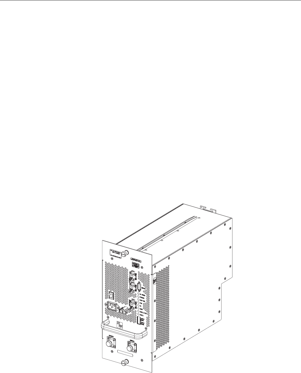
The Spectrum Transport Module (STM), shown in Figure 2-5,serves as the handset servicing
device for the Digivance LRCS. The STM provides the following basic functions:
• Provides an RF interface (antenna ports) to the remote antenna(s).
• Provides an optical interface to the HU.
•Convertsthe digitized forward path optical signal to adigitized RF signal.
•Convertsthe digitized RF signal to acomposite RF signal.
• Digitizes the reverse path composite RF signal.
•Convertsthe digitized reverse path RF signal to adigitized optical signal.
• Provides an RS-232 interface for connecting alocal EMS computer.
• Transports alarm, control, and monitoring information via the optical link.
• Provides AC power input and battery power input.
• Provides external alarm input.
Figure 2-5. Spectrum Transport Module
17528-A
NOTE: UNIT SHOWN INCLUDES
DIVERSITY OPTION
FCC ID: F8I-DVLRCSPCS - User Manual - Part 2

ADCP-75-126 • Issue B • April 2002 • Section 2: Description
Page 2-13
©2002, ADC Telecommunications, Inc.
4.1 Primary Components
The STM consists of an electronic circuit board assembly, power supply, duplexer, and fan
assembly that are mounted within apowder-coated sheet metal enclosure. The metal enclosure
provides amounting point for the electronic components and controls RF emissions. Except for
the fan unit, the electronic components are not user replaceable. The STM is designed for use
within the RU cabinet. Except for the LPA interface connector, all controls, connectors,
indicators, and switches are mounted on the STM front panel for easy access. Acarrying handle
is provided on the front of the STM to facilitate installation and transport.
4.2 Mounting
The STM mounts on ashelf within the RU cabinet. Arunner on the bottom of the STM meshes
with atrack on the mounting shelf. The runner and track guide the STM into the installed
position. The electrical interface between the STM and LPA is supported by aD-sub female
connector located on the rear side of the STM. Acorresponding D-sub male connector mounted
at the rear of the RU cabinet mounting shelf mates with the STM connector. Captive screws are
provided for securing the STM to the mounting shelf.
4.3 Fault Detection and Alarm Reporting
The STM detects and reports various faults including remote unit fault, optical fault, power
fault, temperature fault, power amplifier fault, and external (door open) fault. Various front
panel Light Emitting Diode (LED) indicators turn from green to red or yellow if afault is
detected. The status of the STM, the alarm state (major or minor), and other alarm information
is summarized and reported over the optical fiber to the HU and also over the service interface.
In addition, the alarm state of the HU is received over the optical fiber and reported to the
service interface. This information may be accessed remotely through the NOC/NEM interface
or locally through the EMS software GUI.
4.4 Antenna Cable Connection
The antenna cable connections between the STM and the antenna are supported through either
one (non-diversity unit) or two (diversity unit) N-type female connectors. On non-diversity
units, asingle connector is used for the antenna cable which carries both the forward and
primary reverse path RF signals. On diversity units, asecond connector is used for the diversity
antenna cable which carries only the diversity reverse path RF signals. The STM does not
connect directly to the antenna but instead connects to alightning protector that is mounted on
the bottom of the RU cabinet (see Section 3.5). Acoaxial jumper cable is provided (included
with the enclosure) for connecting the STM connector to the lightning protector.
4.5 RF Signal Level Adjustment
The STM is equipped with adigital attenuator for adjusting the signal level of the forward path
RF output signal. The remote forward path attenuator adjusts the level of the output RF signal
at the RU antenna port and will add from 0to 30 dB of attenuation to the output signal level.

ADCP-75-126 • Issue B • April 2002 • Section 2: Description
Page 2-14
©2002, ADC Telecommunications, Inc.
The attenuator can be set in 1dB increments. The attenuator is software controlled and is
adjusted through the NOC/NEM interface or the EMS software GUI.
4.6 Optical Connection
Fiber optic connections between the STM and the HU are supported through either two (non-
diversity unit) or three (diversity unit) SC-type optical connector ports. On non-diversity units,
one port is used for connecting the forward path optical signal and the other port is used for
connecting the primary reverse path optical signal. On diversity units, athird optical port is used
for connecting the diversity reverse path optical signal.
4.7 Service Interface Connection
The service interface connection between the STM and alocal laptop computer loaded with the
EMS software is supported by asingle DB-9 female connector. The service interface connector
provides an RS-232 DTE interface. The STM service interface connector supports local
communications with both the STM and the corresponding HU.
4.8 Powering
The STM is powered by 120 or 240 Vac (50 or 60 Hz) power which is supplied through athree-
conductor AC power cord. The power cord is provided with the RU cabinet. One end of the cord
is hard-wired to the AC power outlet box and the other end is terminated with amolded-on plug
cap. The power cord connects to a3-wire AC cord connector mounted on the STM front panel.
Aswitch on the STM front panel provides AC power On/Off control.
The STM (and the connected LPA) may be powered by a24 Vdc back-up battery system which
is available as an accessory kit. Aconnector is provided on the STM front panel for connecting
the wiring harness for the back-up battery system.
4.9 Cooling
Continuous air-flow for cooling is provided by asingle fan mounted on the rear side of the STM
housing. An alarm is provided that indicates if ahigh temperature condition (>50º C/122º F)
occurs. If the temperature falls below 32º F(0º C), the fan automatically shuts off. The fan may
be field replaced if it fails.
4.10 User Interface
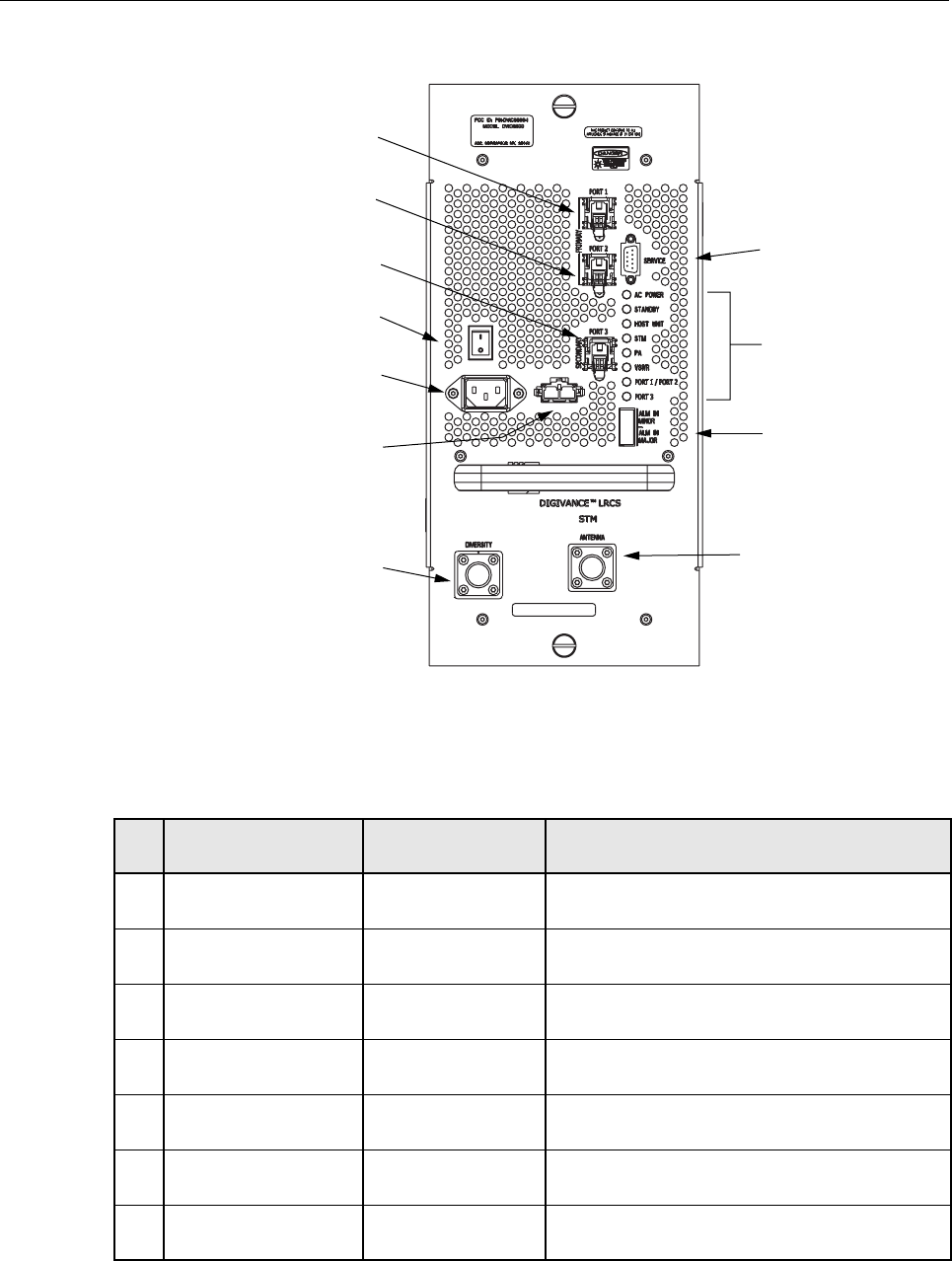
The STM user interface consists of the various connectors, switches, and LEDs that are
provided on the STM front panel. The STM user interface points are indicated in Figure 2-6 and
described in Table 2-3.
ADCP-75-126 • Issue B • April 2002 • Section 2: Description
Page 2-15
©2002, ADC Telecommunications, Inc.
Figure 2-6. Spectrum Transport Module User Interface
Table 2-3. Spectrum Transport Module User Interface
REF
NO
USER INTERFACE
DESIGNATION DEVICE FUNCTIONAL
DESCRIPTION
1PORT1SCconnector
(single-mode) Connection point for the forward path optical
fiber.
2PORT2SCconnector
(single-mode) Connection point for the reverse path primary
optical fiber.
3PORT3
(diversity unit only) SC connector
(single-mode) Connection point for the reverse path diversity
optical fiber.
41/0 On/Offrocker
switch Provides AC power on/off control.
5Nodesignation 3-wire AC power
cord connector Connection point for the AC power cord.
6Nodesignation 2- wire DC power
cord connector Connection point for the back-up battery power
cord.
7 SERVICE DB-9 connector
(female) Connection point for the RS-232 service inter-
face cable.
17527-A
(4) ON/OFF
SWITCH
(5) AC POWER
CONNECTOR
(6) DC POWER
CONNECTOR
(1) PORT 1
CONNECTOR
(2) PORT 2
CONNECTOR
(3) PORT 3
CONNECTOR
NOTE: UNIT SHOWN INCLUDES
DIVERSITY OPTION
(7) SERVICE
CONNECTOR
(8-15) LED
INDICATORS
(16) ALARM
CONNECTOR
(17) DIVERSITY
ANTENNA
CONNECTOR
(18) ANTENNA
CONNECTOR

ADCP-75-126 • Issue B • April 2002 • Section 2: Description
Page 2-16
©2002, ADC Telecommunications, Inc.
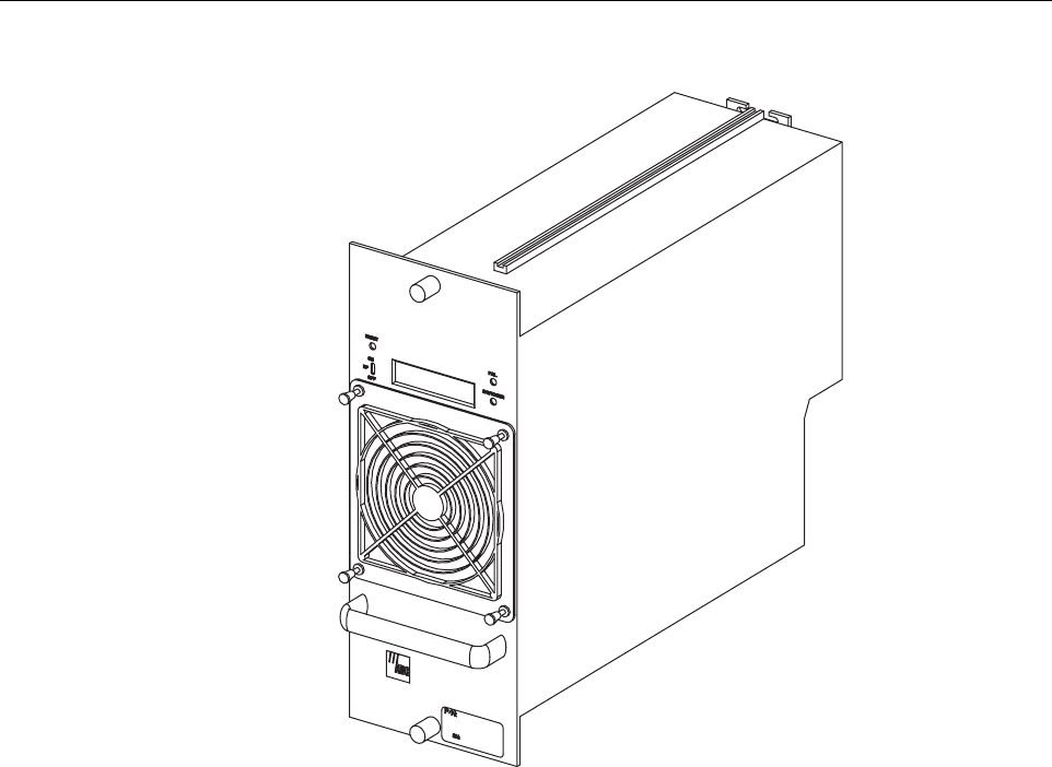
5 LINEAR POWER AMPLIFIER
The Linear Power Amplifier (LPA), shown in Figure 2-7,works is conjunction with the STM to
amplify the forward path RF output signal. The STM is interfaced with the LPA through the D-
sub connectors and wiring harness located at the rear of the RU cabinet. The RF signal is passed
to the LPA for amplification and then passed back to the STM for output via the STM’s
ANTENNA port. The STM also supplies DC power to the LPA through the same interface.
8ACPOWER Multi-colored LED
(green/red)
Indicates if the STM is powered by the AC power
source (green) or the back-up battery system
(red). See Note.
9 STANDBY Multi-colored LED
(green/yellow/red)
Indicates if the system is in the Normal state (off)
Standby state (blinking green), Test state (blink-
ing red), or Program Load state (blinking yel-
low). See Note.
10 HOST UNIT Multi-colored LED
(green/yellow/red)
Indicates if no alarms (green), aminor alarm
(yellow), or amajor alarm (red) is detected at the
HU. See Note.
11 STM Multi-colored LED
(green/yellow/red)
Indicates if the STM is normal (green) or faulty
(red). See Note.
12 PA Multi-colored LED
(green/yellow/red)
Indicates if the power amplifier is normal
(green), over temperature (yellow), has afan fail-
ure (yellow), or is faulty (red). See Note.
13 VSWR Multi-colored LED
(green/yellow/red)
Indicates if the forward path VSWR is above
(red) or below (green) the fault threshold.
14 PORT 1/PORT 2 Multi-colored LED
(green/yellow/red)
Indicates if the forward path optical signal
received from the HU is normal (green), if no sig-
nal is detected (red), or if errors are detected
(red). See Note.
15 PORT 3
(diversity unit only)
Multi-colored LED
(green/yellow)
Indicates if the diversity reverse path optical sig-
nal received by the HU is normal (green), if no
signal is detected (yellow), or if errors are
detected (yellow). See Note.
16 ALARM IN MINOR
ALARM IN MAJOR
Screw-type terminal
connector (14–26
AWG)
Connection point for two external alarm inputs.
The door-open switch lead wires are typically
connected to the major alarm terminals.
17 DIVERSITY
(diversity unit only)
N-type female RF
coaxial connector Connection point for the diversity antenna.
18 ANTENNA N-type female RF
coaxial connector Connection point for the primary antenna.
Note: Amore detailed description of LED operation is provided in Section 5.
Table 2-3. Spectrum Transport Module User Interface, continued
REF
NO
USER INTERFACE
DESIGNATION DEVICE FUNCTIONAL
DESCRIPTION
ADCP-75-126 • Issue B • April 2002 • Section 2: Description
Page 2-17
©2002, ADC Telecommunications, Inc.
Figure 2-7. Linear Power Amplifier
5.1 Primary Components
The LPA consists of several electronic circuit board assemblies and two fan assemblies that are
mounted within apowder-coated sheet metal enclosure. The metal enclosure provides a
mounting point for the electronic components and controls RF emissions. Except for the fan
units, the electronic components are not user replaceable. The LPA is designed for use within
the RU cabinet. Except for the STM interface connector, all controls, indicators, and switches
are mounted on the LPA front panel for easy access. Acarrying handle is provided on the front
of the LPA to facilitate installation and transport.
5.2 Mounting
The LPA mounts on ashelf within the RU cabinet. Runners on the top and bottom of the LPA
mesh with tracks on the mounting shelf. The runners and tracks guide the LPA into the installed
position. The electrical interface between the STM and LPA is supported by aD-sub female
connector located on the rear side of the LPA. Acorresponding D-sub male connector mounted
at the rear of the RU cabinet mounting shelf mates with the LPA connector. Captive screws are
provided for securing the LPA to the mounting shelf.
17546-A
LPA 1940

ADCP-75-126 • Issue B • April 2002 • Section 2: Description
Page 2-18
©2002, ADC Telecommunications, Inc.
5.3 Fault Detection and Alarm Reporting
The LPA in conjunction with the STM detects and reports various faults including power
amplifier fault, output power fault, temperature fault, and fan fault. Various Light Emitting
Diode (LED) indicators, located on the front panels of both the STM and LPA, turn from green
to red or yellow if an LPA fault is detected. In addition, adigital display located on the LPA
front panel provides various fault messages. The status of the LPA, the alarm state (major or
minor), and other more detailed information is summarized and reported (by the STM) over the
optical fiber to the HU and also to the service interface. This detailed information may be
accessed remotely through the NOC/NEM interface or locally through the EMU software GUI.
5.4 Powering
The LPA is powered by various DC voltages which are supplied by the STM over the electrical
interface provided by the D-sub connectors and wiring harness mounted within the RU cabinet.
5.5 Cooling
Continuous air-flow for cooling is provided by apair of fans mounted at the front and the rear
side of the LPA housing. The front fan pulls cool air into the module and the rear fan exhausts
heated air out of the module. An alarm is provided that indicates if ahigh temperature condition
(>50º C/122º F) occurs or if afan failure occurs. Either fan may be field replaced if it fails.
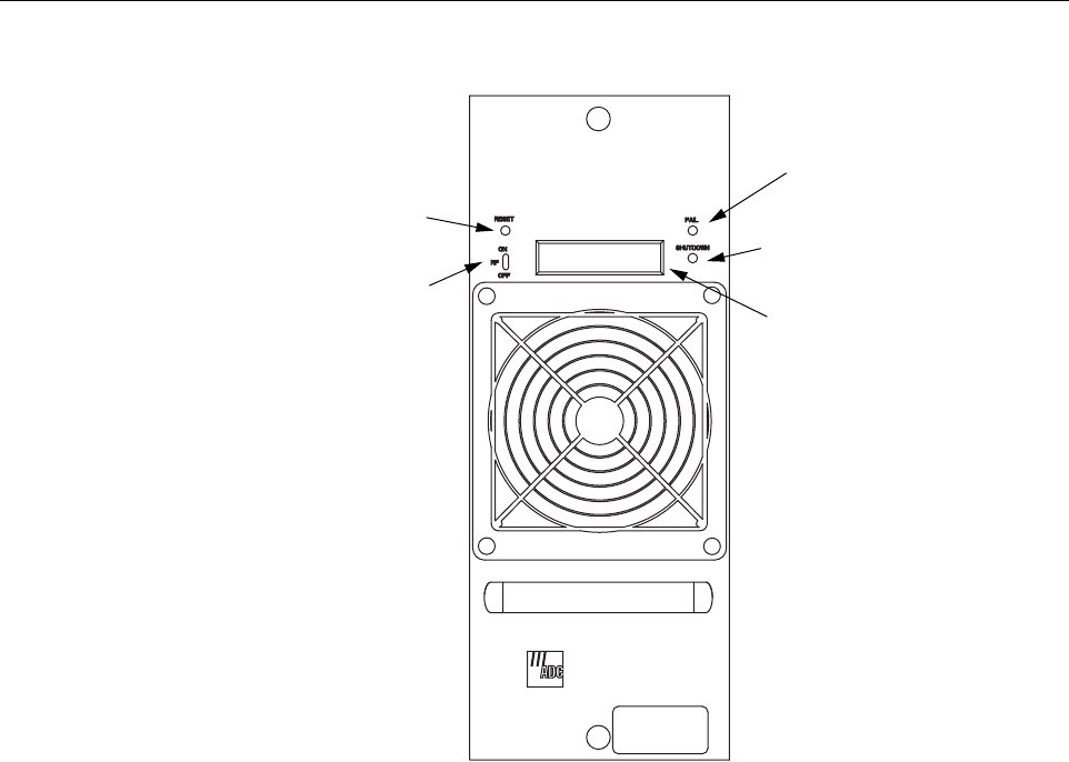
5.6 User Interface
The LPA user interface consists of the various LEDs, message displays, and switches that are
provided on the LPA front panel. The LPA user interface points are described in Table 2-4 and
indicated in Figure 2-8.
Table 2-4. Linear Power Amplifier User Interface
REF
NO
USER INTERFACE
DESIGNATION DEVICE FUNCTIONAL
DESCRIPTION
1 RESET Momentary contact
push button switch Momentarily pressing the switch push button
clears all alarms and restarts the amplifier
2RFON OFF 2-position switch Placing the switch in the OFF position puts the
LPA in astandby state with RF output disabled.
Placing the switch in the ON position puts the
LPA in the normal state with RF output enabled.
3FAIL LEDindicator
(yellow) Indicates the LPA is normal (off) or faulty
(yellow).
4 SHUTDOWN LED indicator (red) Indicates the LPA is in service (off) or shutdown
(red).
5Nodesignation Digital display Provides status and alarm messages. See Note.
Note: Amore detailed description of the digital display messages is provided in Section 5.
ADCP-75-126 • Issue B • April 2002 • Section 2: Description
Page 2-19
©2002, ADC Telecommunications, Inc.
Figure 2-8. Linear Power Amplifier User Interface
6 DIGIVANCE ELEMENT MANAGEMENT SYSTEM
The Digivance Element Management System (EMS) is anetwork management tool that provides
control and monitoring functions for the Digivance LRCS system. The EMS is used to provision
and configure new systems for operation, set system operating parameters, get system alarm and
status messages, and upgrade the system software. The EMS supports both local control by an
on-site service technician and remote control by aNetwork Operations Center (NOC).
6.1 Primary Components
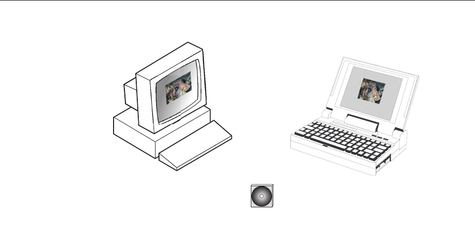
The EMS, shown in Figure 2-9,consists of aPC-type desk-top computer (not provided) that is
loaded with the EMS software. The EMS software is stored on aCD-ROM that is shipped with
the HU. The EMS software must be installed on the EMS computer along with the Java 2
Version 1.3.1 Runtime Environment software which is also provided. Installation consists of
inserting the CD-ROM into the computer’s CD-ROM drive and then running the software install
programs. This places the Java 2Runtime Environment and EMS software files in assigned
folders on the computer’s hard drive.
(1) RESET
SWITCH
(2) RF ON/OFF
SWITCH
(3) FAIL
LED
(4) SHUTDOWN
LED
(5) DIGITAL
DISPLAY
17545-A
LPA 1940
ADCP-75-126 • Issue B • April 2002 • Section 2: Description
Page 2-20
©2002, ADC Telecommunications, Inc.
Figure 2-9. Alarm Network Unit
The EMS software may also be installed on aPC-type lap-top computer (not provided). Alap-
top version of the EMS computer can be used as aportable network management tool for
service and maintenance purposes. Alaptop EMS can be connected temporarily to asystem to
enter the initial configuration data or to trouble-shoot problems and then removed when the task
is completed. Permanent control and monitoring functions would be provided by the desk-top
EMS computer.
6.2 Service Interface Connection
The service interface connection between the EMS computer and the HU or RU requires that
the EMS computer be equipped with aDB-9 connector that is configured to provide an RS-232
DCE interface. Astraight-through RS-232 interface cable (accessory item) equipped with a
male DB-9 connector on one end and aPC-compatible connector on the other end is required to
link the EMS computer to the HU. When multiple HUs are networked together, the EMS
computer may be connected to the service connector on any one of the networked HUs.
6.3 NOC Interface Connection
The NOC interface connection between the EMS computer and the NOC requires that the EMS
computer be equipped with aconnector that is configured to provide an RS-232 ASCII
interface. The link between the EMS computer and the NOC would generally be supported by a
data network or dial-up modem. Cables and equipment (not provided) to support the RS-232
interface connection between the EMS computer and the data network or dial-up modem are
required.
CD-ROM WITH EMS
SOFTWARE
OR
PLUS
16803-A
ADCP-75-126 • Issue B • April 2002 • Section 2: Description
Page 2-21
©2002, ADC Telecommunications, Inc.
6.4 EMS Software User Interface
The EMS software provides two user interfaces: the Graphical User Interface (GUI) and the
Network Operation Center-Network Element Manager (NOC/NEM) interface. Both interfaces
provide essentially the same functionality except only the GUI can upgrade the LRCS system
with new system software. In addition, only the NOC/NEM interface can record and playback
alarm data.
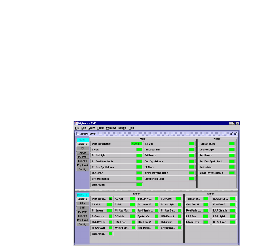
The GUI is presented at the EMS computer or on alaptop computer. The GUI is used for local
control and monitoring operations. The GUI consists of aseries of displays and screens, such as
the one shown in Figure 2-10,that provide the user with alarm and status information and that
allow the user to set various operating parameters.
Figure 2-10. EMS Graphical User Interface Host/Remote Display
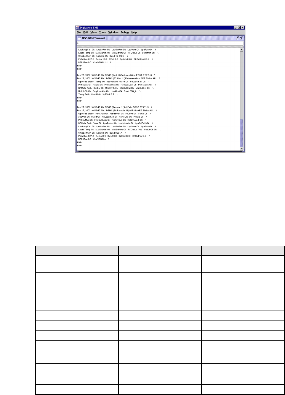
The NOC/NEM interface is acommand line interface that is presented at an NOC terminal. The
NOC/NEM interface is used for remote control and monitoring operations. The NOC/NEM
interface consists of ASCII text strings that are input as SET or GET commands which are
followed by the action or information required. Atext string response is received from the
specified LRCS system or systems to confirm the requested action or to report the requested
information. Examples of several typical NOC-NEM interface commands and the responses
received are shown in Figure 2-11.The NOC/NEM interface requires only aVT100 terminal/
emulator or aPC-type computer that is loaded with acommunication software such as
Procomm Plus. While primarily intended for use at the NOC, the NOC/NEM interface
commands may also be input from the EMS computer.
ADCP-75-126 • Issue B • April 2002 • Section 2: Description
Page 2-22
©2002, ADC Telecommunications, Inc.
Figure 2-11. NOC/NEM Interface Typical Commands
7 SPECIFICATIONS
Refer to Table 2-5 for the Digivance 1900 MHz LRCS system nominal specifications. All
specifications apply after afive minute warm-up period.
Table 2-5. 1900 MHz System Nominal Specifications
PARAMETER SPECIFICATION REMARKS
Optical - Host and Remote Unit
Fiber type 9/125, single-mode
Number of fibers required
Non-diversity with WDM
Diversity with WDM
Non-diversity without WDM
Diversity without WDM
1
2
2
3
The wavelength division multi-
plexer (WDM) is an accessory
item.
Forward path wavelength 1550 nm
Reverse path wavelength 1310 nm
Diversity path wavelength 1310 nm
Optical transmit power output
Host Unit
Remote Unit 0dBm
+2 dBm
Optical budget 25 dB For optical BER of 10–6
Optical Receive Input –15 dBm
Optical connectors Industry standard SC Host, remote, and WDM

ADCP-75-126 • Issue B • April 2002 • Section 2: Description
Page 2-23
©2002, ADC Telecommunications, Inc.
RF Forward Path - 1900 MHz
System bandwidth 20 MHz AD band, 25 MHz
DBE,BEF, and EFC bands
Frequency range
AD
DBE
BEF
EFC
1930 to 1950 MHz
1945 to 1970 MHz
1950 to 1975 MHz
1965 to 1990 MHz
Out-of-band emissions
Primary
Secondary (see Note 1)
–13 dBm per 1MHz bandwidth
from 10 kHz to 20 GHz
–98 dBm per 100 kHz from 824
to 849 MHz and from 1850 to
1910 MHz
Gain of forward path
(Host input to Remote primary
antenna port)
83.5 dB at band center, room
temperature, and 0dB attenua-
tion setting
Includes power amplifier.
Gain flatness
Band flatness
Channel flatness ±1.5 dB across freq. range
±1 dB variation across any 1.25
MHz channel
Gain variation ± 3dB over temp and unit-to-
unit
Out-of-band rejection –40 dB at >±17.5 MHz from
881.5 MHz
Propagation delay 2.2 µs Excludes fiber delay
Configurable propagation delay
Range
Step size Up to 63 µs
1µs ± 100 ns
Plus standard propagation delay
Spurious
In-band self generated
Free dynamic range –13 dBm at remote output
60 dB at 30 kHz bandwidth
Transmit peak-to-average 10 dB
Two-tone Intermodulation –55 dBc at remote output Two tones at 5Watts each
CDMA Intermodulation
885 kHz to 1.25 MHz
1.25 to 1.98 MHz
1.98 to 2.25 MHz
–45 dBc per 30 kHz
–8 dBm per 30 kHz
–55 dBc per 30 kHz Absolute level
Nominal composite RF input
signal level –40 dBm at 0dB attenuation
–10 dBm at max. attenuation An input signal level of –40 dBm
provides maximumoutput power
Configurable input level
Range
Step size 30 dB
1 ± 0.5 dB ±10% of attenuation
monotonic
Table 2-5. 1900 MHz System Nominal Specifications, continued
PARAMETER SPECIFICATION REMARKS

ADCP-75-126 • Issue B • April 2002 • Section 2: Description
Page 2-24
©2002, ADC Telecommunications, Inc.
Composite RF Output power 43.5 dBm (22.4 Watts) at remote
antenna port with –40 dBm input 40 Watts at power amplifier out-
put
Configurable RF Output
Range
Step size 30 dB at remote unit
1±0.5 dB ±10% of attenuation
monotonic
Transmit path insertion loss 2.5 dB
RF Reverse Path - 1900 MHz
System bandwidth 20 MHz AD band, 25 MHz
DBE,BEF, and EFC bands
Frequency range
AD
DBE
BEF
EFC
1850 to 1870 MHz
1865 to 1890 MHz
1870 to 1895 MHz
1885 to 1910 MHz
In band spurs (caused by an indi-
vidual out-of-band signal) –75 dBc (1 MHz to 20 GHz
and >10 MHz out-of-band)
–120 dBc (1930 to 1990 MHz)
–120 dBc (869 to 894 MHz) Required for dual band
Propagation delay 2.2 µs Excludes fiber delay
Configurable propagation delay
Range
Step size Up to 60 µs
1µs
Plus standard propagation delay
Gain flatness
Band flatness
Channel flatness
1.5 dB across frequency range
±1 dB variation across any 1.25
MHz channel
Gain of reverse path
Overall gain
Gain variation
30 dB at band center at room
temperature
3dB over temperature
ALC not invoked
ALC not invoked
Out-of-band rejection –40 dB at >±17.5 MHz from
836.6 MHz ALC not invoked
Spurious (in-band self gener-
ated) –110 dBm referred to input ALC not invoked
Intermodulation –62 dBc two tones at –50 dBm
System noise figure 8 dB ALC not invoked
Configurable RF output
Range
Step size 30 dB
1±0.5 dB ±10% of attenuation
monotonic
Blocking dynamic range 70 dB
Level limiting ALC threshold –40 dBm instantaneous
Level limiting ALC range 30 dB
Table 2-5. 1900 MHz System Nominal Specifications, continued
PARAMETER SPECIFICATION REMARKS

ADCP-75-126 • Issue B • April 2002 • Section 2: Description
Page 2-25
©2002, ADC Telecommunications, Inc.
Physical/Environmental/
Electrical - Host Unit
Dimensions (H×W×D) 3.5 × 17.2 × 15.3 inches
(89 ×437 ×389 mm) Dimension for width does not
include the mounting brackets
which can be installed for either
19- or 23-inch racks.
Mounting 19- or 23-inch rack EIA or WECO
Weight 18 lbs. (8.2 kg)
Weather resistance Indoor installation only
Operating temperature 0º to 50º C(32º to 122º F)
Storage temperature –40º to 70º C(–40º to 158ºF)
Humidity 10% to 90% No condensation
External alarm connector Screw-type terminals NO and NC relay contacts
DC power connector Screw-type terminal strip
RF coaxial cable connectors N-type (female)
Service connector DB-9 (female) RS-232 DTE interface
CAN connectors RJ-45 jack
Power input ± 24 or ±48 Vdc
Power consumption 55 watts
Current rating 1 Amp at –48 Vdc
Reliability at 25ºC MTBF 80,000 hours Excluding fans
Physical/Environmental/
Electrical - Remote Unit
Cabinet dimensions (H×W×D) 28.4 × 17.4 × 24.9 inches
(721 ×442 ×632 mm)
Mounting Wall or pole Pole mounting requires the pole
mount kit. (accessory)
Weight 120 lbs (54.4 kg) Includes modules but not battery
Weather resistance NEMA-3R, removable dust filter
Operating temperature –30º to 50º C(–22º to 122º F)
Storage temperature –40º to 70º C(–40º to 158ºF)
Humidity 10% to 90% No condensation
External alarm connector Screw-type terminals External alarm inputs
AC power connection 3/4- or 1/2-inch conduit Per local code or practice.
Antenna cable connector N-type (female)
Fiber optic cable size 0.375 to 0.875 inch (10 to 22
mm) diameter cable 9/125, single-mode
Table 2-5. 1900 MHz System Nominal Specifications, continued
PARAMETER SPECIFICATION REMARKS

ADCP-75-126 • Issue B • April 2002 • Section 2: Description
Page 2-26
©2002, ADC Telecommunications, Inc.
Note 1: Required for co-located sites such as dual band. Otherwise, the emissions from one unit
can limit the sensitivity of the other.
Lightning protection 20 kA IEC 1000-4-5 8/20 µs
waveform
Service connector DB-9 (female) RS-232 DTE interface
Battery backup operation 1 hour
Power input 120 or 240 VAC , 50 or 60 Hz Operation on 240 VAC requires
removal of the 120 VAC outlet.
Power consumption 1200 watts
Current rating 9 Amps at 120 Vac
Reliability at 25ºC MTBF 50,000 hours Excluding fans, battery, and air
filter
Table 2-5. 1900 MHz System Nominal Specifications, continued
PARAMETER SPECIFICATION REMARKS

ADCP-75-126 • Issue B • April 2002 • Section 3: Host Unit Installation
Page 3-1
©2002, ADC Telecommunications, Inc.
SECTION 3: HOST UNIT INSTALLATION
1 BEFORE STARTING INSTALLATION . . . . . . . . . . . . . . . . . . . . . . . . . . . . . . . . . . . . . . . . . . . . . . . . . . . . . . . . . .3-1
1.1 Tools and Materials . . . . . . . . . . . . . . . . . . . . . . . . . . . . . . . . . . . . . . . . . . . . . . . . . . . . . . . . . . . . . . .3-1
1.2 Unpacking and Inspection. . . . . . . . . . . . . . . . . . . . . . . . . . . . . . . . . . . . . . . . . . . . . . . . . . . . . . . . . . .3-2
2 OSP FIBER CABLE INSTALLATION GUIDELINES . . . . . . . . . . . . . . . . . . . . . . . . . . . . . . . . . . . . . . . . . . . . . . . . . .3-2
3 WDM MOUNTING PROCEDURE (OPTIONAL ACCESSORY) . . . . . . . . . . . . . . . . . . . . . . . . . . . . . . . . . . . . . . . . . . .3-4
4 HU MOUNTING PROCEDURE . . . . . . . . . . . . . . . . . . . . . . . . . . . . . . . . . . . . . . . . . . . . . . . . . . . . . . . . . . . . . . .3-6
5 CHASSIS GROUND CONNECTION . . . . . . . . . . . . . . . . . . . . . . . . . . . . . . . . . . . . . . . . . . . . . . . . . . . . . . . . . . . .3-8
6 COAXIAL CABLE CONNECTIONS. . . . . . . . . . . . . . . . . . . . . . . . . . . . . . . . . . . . . . . . . . . . . . . . . . . . . . . . . . . . .3-8
7 OPTICAL CONNECTIONS. . . . . . . . . . . . . . . . . . . . . . . . . . . . . . . . . . . . . . . . . . . . . . . . . . . . . . . . . . . . . . . . . 3-10
7.1 Optical Connections Without WDM. . . . . . . . . . . . . . . . . . . . . . . . . . . . . . . . . . . . . . . . . . . . . . . . . . . . 3-10
7.2 Optical Connections With WDM . . . . . . . . . . . . . . . . . . . . . . . . . . . . . . . . . . . . . . . . . . . . . . . . . . . . . . 3-11
8 CONTROLLER AREA NETWORK CONNECTIONS . . . . . . . . . . . . . . . . . . . . . . . . . . . . . . . . . . . . . . . . . . . . . . . . . 3-13
9 SERVICE INTERFACE CONNECTION . . . . . . . . . . . . . . . . . . . . . . . . . . . . . . . . . . . . . . . . . . . . . . . . . . . . . . . . . 3-14
10 EXTERNAL ALARM SYSTEM CONNECTIONS . . . . . . . . . . . . . . . . . . . . . . . . . . . . . . . . . . . . . . . . . . . . . . . . . . . 3-15
11 DC POWER CONNECTIONS . . . . . . . . . . . . . . . . . . . . . . . . . . . . . . . . . . . . . . . . . . . . . . . . . . . . . . . . . . . . . . . 3-16
_________________________________________________________________________________________________________
1 BEFORE STARTING INSTALLATION
This section provides the installation procedures for the HU, the WDM mounting shelf
(accessory item), and the WDM (accessory item). Installation of the RU cabinet and RU
electronic modules may proceed separately from installation of the HU. The installation
procedures for the single band remote cabinet are provided in the Digivance Long-Range
Coverage Solution Single Band Remote Cabinet Mounting Instructions (ADCP-75-117) which
are shipped with the cabinet. The installation procedures for the STM and LPA electronic
modules are provided in the Digivance Long-Range Coverage Solution Remote Unit
Installation Instructions which are shipped with the STM. When all units of the Digivance
LRCS have been installed, refer to Section 4of this manual for the system turn-up and test
procedures.
Before beginning the installation, review the system design plan with the system engineer.
Make sure each equipment installation site is identified and located and all cable runs are
mapped out.
1.1 Tools and Materials
The following tools are required to complete the procedures in this section:
•Boxcutter
• Pencil or scribe
•Mediumsize flat-bladed screwdriver
• Phillips screwdriver (#2)
Content Page

ADCP-75-126 • Issue B • April 2002 • Section 3: Host Unit Installation
Page 3-2
©2002, ADC Telecommunications, Inc.
•TORXscrewdriver (T20 bit)
• Pliers
•Wirecutters
•Wirestripper
• Tool kit for attaching N-type male connectors to coaxial cable
• Multimeter
•Opticalpower meter
• Laser light source
The following materials are required to complete the procedures in this section:
• #18 AWG (1.0 mm) insulated stranded copper wire (for chassis grounding wire)
• #18 AWG (1.0 mm) red and black insulated copper wire (for DC power wires)
• Category 3or 5cable (for external alarm system wires)
•#6ring terminal (1) for #18 wire (for chassis ground wire connection)
•#6fork terminals (2) for #18 wire (for DC power wiring connection)
• Single-mode patch cord(s) with SC connectors (1, 2or 3depending on the application)
•Highperformance, flexible, low-loss 50-ohm coaxial cable
• N-type male connectors
•Wireties
1.2 Unpacking and Inspection
This section provides instructions for opening the shipping boxes, verifying that all parts have
been received, and verifying that no shipping damage has occurred. Use the following
procedure to unpack and inspect the HU and any accessories:
1. Open the shipping cartons and carefully unpack each component from the protective
packing material.
2. Check each component for broken or missing parts. If there are damages, contact ADC
(see section 6at the end of this manual) for an RMA (Return Material Authorization) and
to reorder if replacement is required.
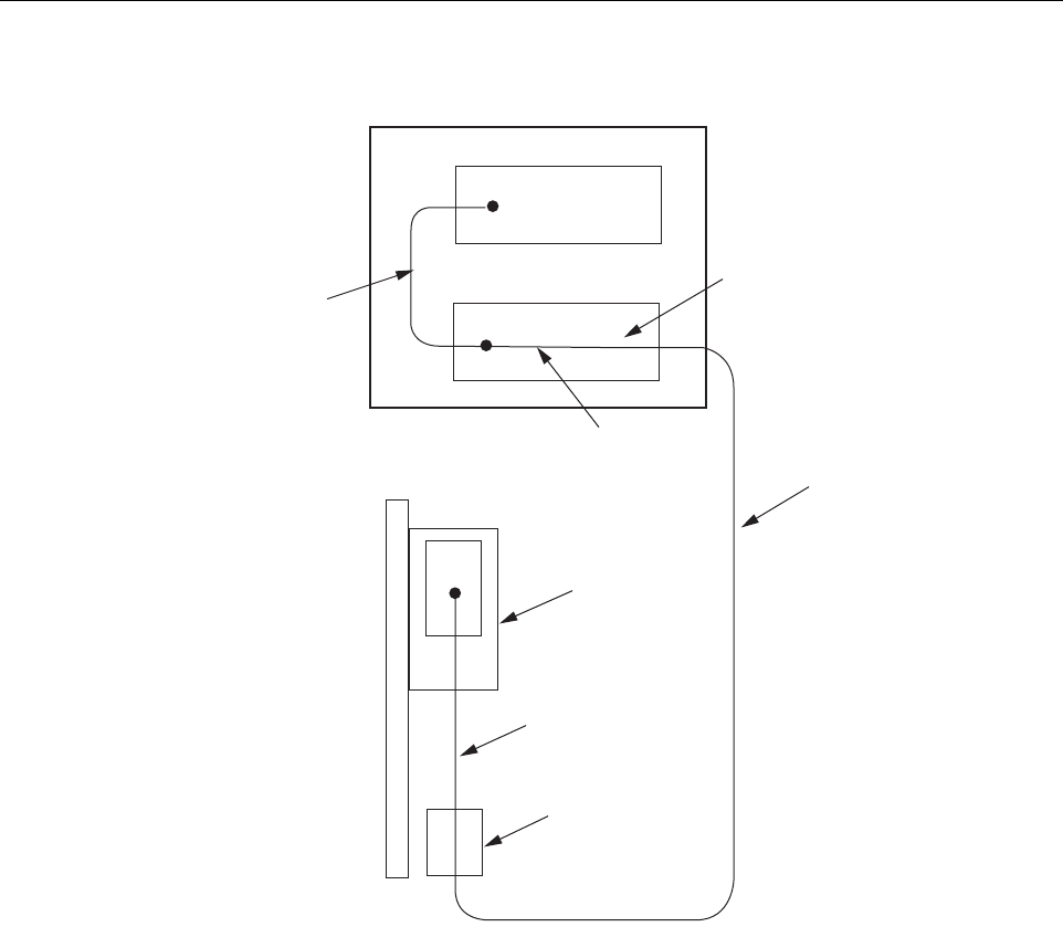
2 OSP FIBER CABLE INSTALLATION GUIDELINES
The outside plant (OSP) fiber optic cables should be routed between the HU and RU and
terminated before the equipment is installed. Adiagram of atypical OSP cable routing is shown
in Figure 3-1.At the HU, the OSP cable should be terminated at afiber distribution panel and
spliced to pigtails. Jumper patch cords may then be used to link the HU optical ports to the OSP
cable terminations. Whenever possible, aguideway such as the FiberGuide system should be
provided to protect the fiber optic patch cords from damage and to prevent excessive bending.
The procedures for connecting the OSP cable optical fibers to the HU is provided in Section 7.
ADCP-75-126 • Issue B • April 2002 • Section 3: Host Unit Installation
Page 3-3
©2002, ADC Telecommunications, Inc.
Figure 3-1. Typical OSP Cable Routing
At the RU, the OSP fiber optic cable should be spliced to aconnectorized outdoor-rated cable
(consisting of individual jacketed pigtails) which is routed into the RU cabinet. The individual
pigtails can then be connected directly to the STM optical ports. Aconnector is provided on the
bottom of the RU cabinet to seal the cable entry point and provide strain relief. The procedure
for routing the fiber cable into the RU cabinet and for connecting the pigtail leads to the STM is
provided in the Digivance LRCS Single Band SMR Remote Unit Installation Instructions
(ADCP-75-122).
When all splices and terminations are completed, test each fiber for optical loss as described in
Section 5 of this document. The optical loss budget for 9/125, single-mode fiber is 25 dB
minimum for an optical BER of 10-6.The power level of the received optical signal should not
exceed –15 dBm to avoid overdriving the optical receiver. If necessary, use an in-line optical
attenuator to adjust the signal level.
HOST UNIT
FIBER DISTRIBUTION PANEL
X
X
STM
REMOTE SITE
HOST SITE
PATCH
CORD
SPLICE
PIGTAIL
SPLICE
ENCLOSURE
INDOOR/OUTDOOR
CABLE WITH
PIGTAIL LEADS
OUTSIDE PLANT
CABLE
REMOTE UNIT
CABINET
16889-A
ADCP-75-126 • Issue B • April 2002 • Section 3: Host Unit Installation
Page 3-4
©2002, ADC Telecommunications, Inc.
3 WDM MOUNTING PROCEDURE (OPTIONAL ACCESSORY)
Abi-directional wavelength division multiplexer (WDM) is available as an accessory item for
non-diversity versions of the Digivance LRCS. If the application does not require the use of a
WDM, skip this section and proceed to Section 4.
The version of the WDM that is used with the HU consists of one or two WDM modules and a
WDM mounting shelf. Each WDM module can support two HU’s and each WDM mounting
shelf can hold two WDM modules. Afully loaded WDM mounting shelf can therefore support
four HU’s.
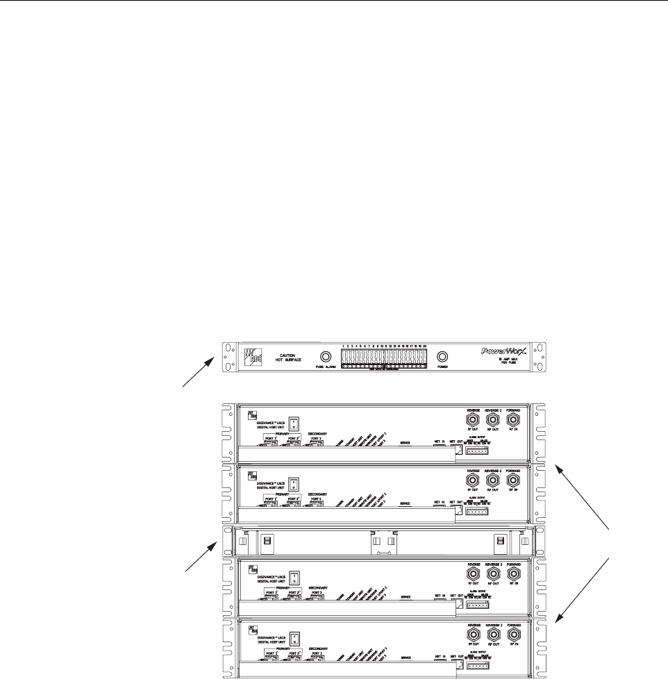
When multiple HU’s require connection to aWDM, the WDM mounting shelf and the HU’s
should be mounted in the equipment rack as shown in Figure 3-2.This configuration allows the
pigtail leads from the two WDM modules to be connected directly to the optical ports on any
one of the four HU’s.
Figure 3-2. Typical WDM and HU Configuration
The WDM mounting shelf may be mounted in either a19-inch or 23-inch EIA or WECO
equipment rack. Four #12-24 screws are provided for securing the mounting shelf to the rack.
Use the following procedure to install the WDM mounting shelf in the equipment rack and to
mount the WDM modules in the WDM mounting shelf:
1. The WDM mounting shelf is shipped with the mounting brackets installed for 19-inch EIA
rack installations. If installing the mounting shelf in a19-inch EIA rack, proceed to step 5.
If installing the mounting shelf in a19-inch WECO rack, a23-inch EIA rack, or a23-inch
WECO rack, proceed to step 2.
WDM MOUNTING
SHELF
(WITHOUT MODULES)
16886-A
POWERWORX
FUSE PANEL
HOST UNITS
ADCP-75-126 • Issue B • April 2002 • Section 3: Host Unit Installation
Page 3-5
©2002, ADC Telecommunications, Inc.
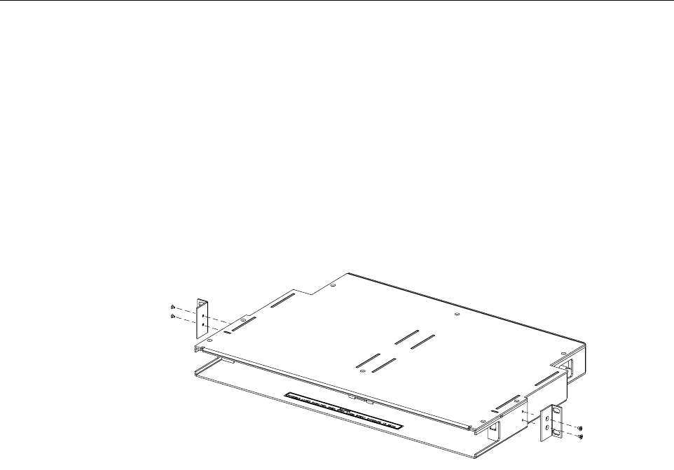
2. Remove both mounting brackets from the mounting shelf (requires Phillips screwdriver)
and save screws for reuse.
3. Locate the extra mounting brackets that are provided with the mounting shelf and select
the brackets that correspond to the rack type. Each mounting shelf includes extra brackets
for installing the mounting shelf in the rack types specified in step 1.
4. Install the replacement mounting brackets as shown in Figure 3-3.Use the screws
removed in step 2to attach the new brackets to the mounting shelf.
Figure 3-3. Installing the Replacement Mounting Brackets
5. Position the WDM mounting shelf in the designated mounting space in the rack (per
system design plan) and then secure the mounting brackets to the rack using the four #12-
24 machine screws provided as shown in Figure 3-4.
6. Install each WDM module in the mounting shelf (see Figure 3-4). Arail on the side of the
module fits into aguide within the mounting.
7. Secure each WDM module to the mounting shelf by twisting the handle on each quarter-
turn fastener 90º.
8. Carefully store the pigtail leads from each WDM module. The routing and connection
procedures for the pigtails are provided in Section 7.
16885-A