ADC Telecommunications DVLRCSPCS Digivance Long-Range Coverage Solution Single Band User Manual 75126
ADC Telecommunications Inc Digivance Long-Range Coverage Solution Single Band 75126
Contents
- 1. manual 1
- 2. manual 2
- 3. manual
manual
ADCP-75-126 • Issue B • April 2002 • Section 3: Host Unit Installation
Page 3-6
©2002, ADC Telecommunications, Inc.
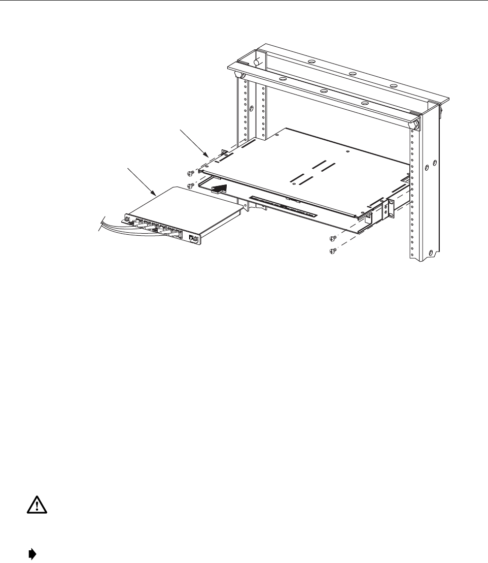
Figure 3-4. WDM Mounting Shelf and WDM Module Installation
4 HU MOUNTING PROCEDURE
The HU may be mounted in either a19-inch or 23-inch EIA or WECO equipment rack. Both
US standard and metric machine screws are included for rack mounting the HU. When loading
the HU in arack, make sure the mechanical loading of the rack is even to avoid ahazardous
condition such as aseverely unbalanced rack. The rack should safety support the combined
weight of all the equipment it holds. In addition, maximum recommended ambient temperature
for the HU is 50º C(122º F). Allow sufficient air circulation or space between units when the
HU is installed in amulti-rack assembly because the operating ambient temperature of the rack
environment might be greater than room ambient.
Use the following procedure to install the HU in the equipment rack:
1. The HU is shipped with the mounting brackets installed for 19-inch rack installations. If
mounting the HU in a19-inch rack, proceed to step 4. If mounting the HU in a23-inch
rack, proceed to step 2.
2. Remove both mounting brackets from the HU (requires TORX screwdriver with T20 bit)
and save screws for reuse.
Warning: Wet conditions increase the potential for receiving an electrical shock when
installing or using electrically powered equipment. To prevent electrical shock, never install or
use electrical equipment in awet location or during alightning storm.
Note: To insure that all optical connectors remain dust-free during installation, leave all dust
caps and dust protectors in place until directed to remove them for connection.
16888-A
WDM MODULE
WDM MOUNTING
SHELF
FCC ID: F8I-DVLRCSPCS - User Manual - Part 3
ADCP-75-126 • Issue B • April 2002 • Section 3: Host Unit Installation
Page 3-7
©2002, ADC Telecommunications, Inc.
3. Reinstall both mounting brackets so the long side of the bracket is flush with the HU front
panel as shown in Figure 3-5.Use the screws removed in step 2to re-attach the brackets to
the HU chassis.
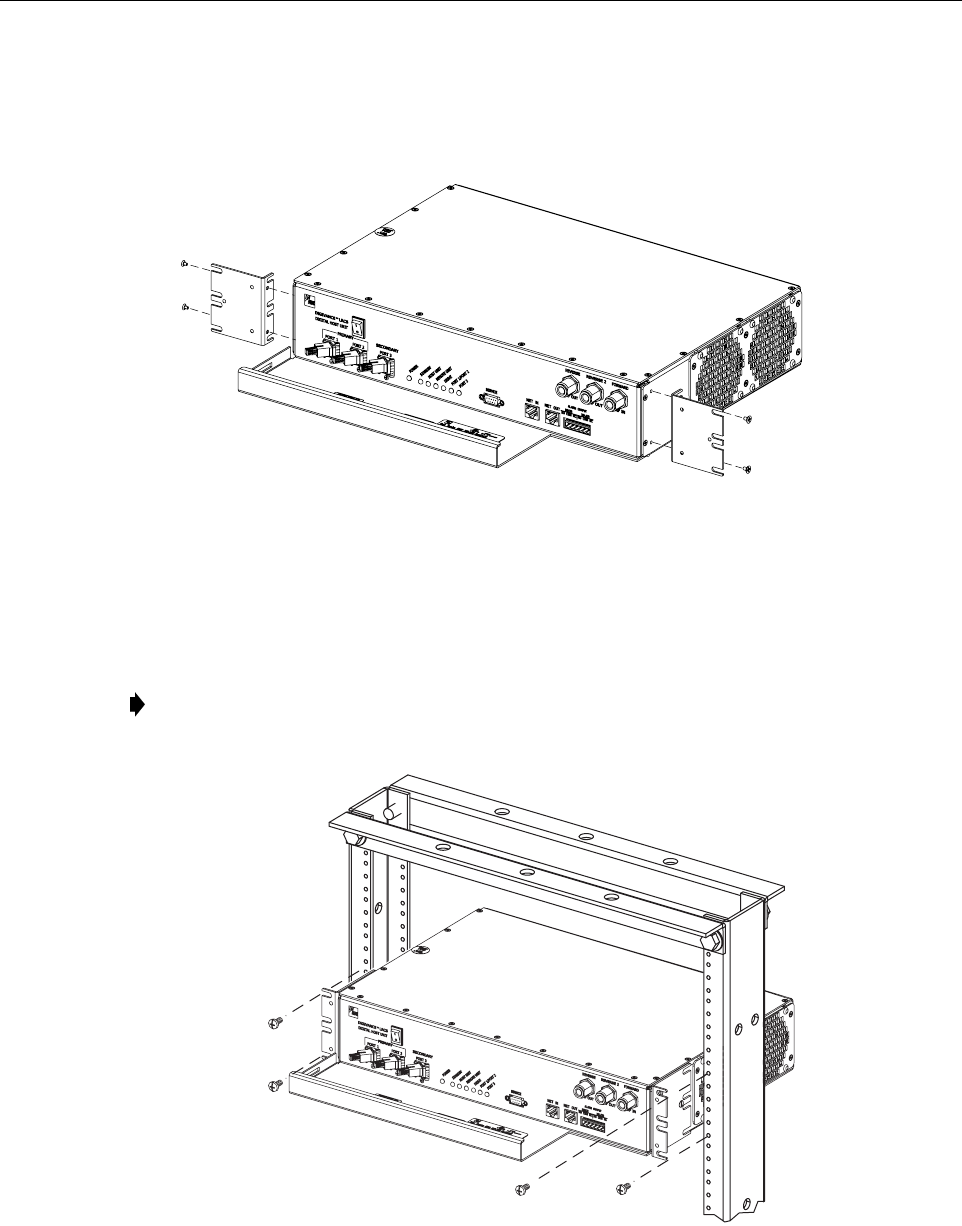
Figure 3-5. Installing the Mounting Brackets for 23-Inch Rack Installations
4. Position the HU in the designated mounting space in the rack (per system design plan) and
then secure the mounting brackets to the rack using the four machine screws provided (use
#12-24 or M6 x10 screws, whichever is appropriate) as shown in Figure 3-6.
Figure 3-6. HU Rack Mount Installation
Note: Provide aminimum of 3inches (76 mm) of clearance space on both the left and
right sides of the HU for air intake and exhaust.
16882-A
REMOVE AND REINSTALL MOUNTING
BRACKETS AS SHOWN FOR
INSTALLATION IN 23-INCH RACKS
16883-A
ADCP-75-126 • Issue B • April 2002 • Section 3: Host Unit Installation
Page 3-8
©2002, ADC Telecommunications, Inc.
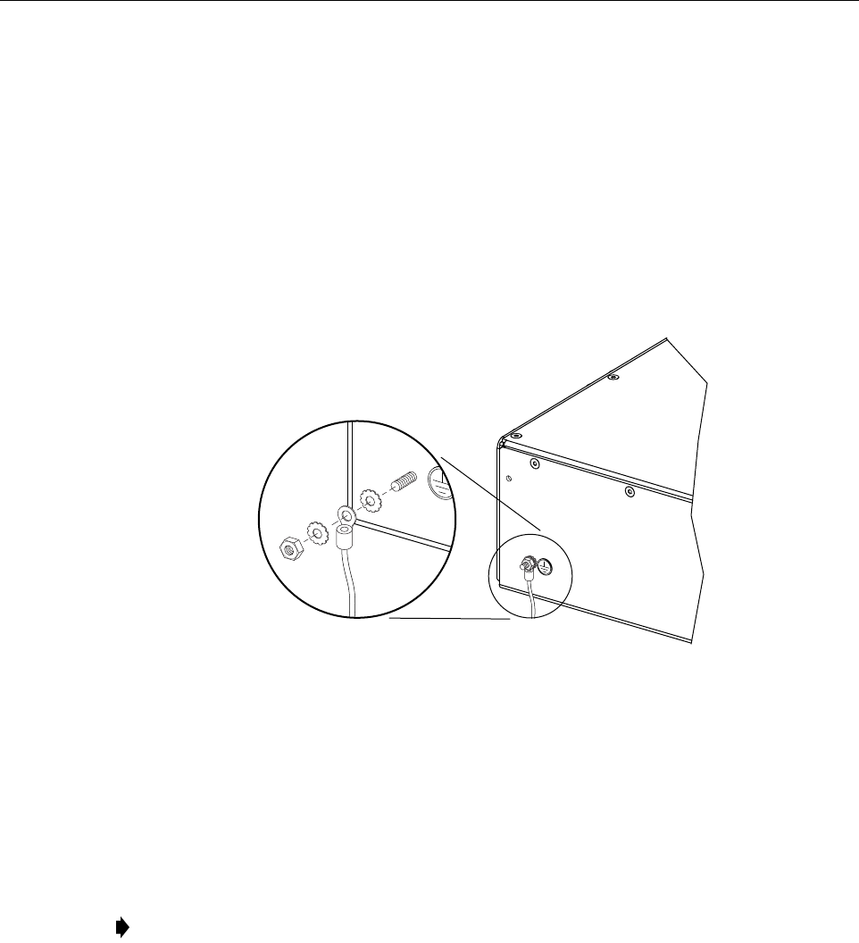
5 CHASSIS GROUND CONNECTION
Astud is provided on the rear side of the chassis for connecting agrounding wire to the chassis.
Use the following procedure to connect the grounding wire to the chassis and to route the
grounding wire to an approved earth ground source.
1. Obtain alength of #18 AWG (1.00 mm) insulated stranded copper wire for use as a
chassis grounding wire.
2. Terminate one end of the wire with aring terminal.
3. Locate the chassis ground stud at the rear of the HU as shown in Figure 3-7.
Figure 3-7. Chassis Ground Stud
4. Attach the ring end of the wire to the chassis ground stud (see Figure 3-7).
5. Route the free end of the chassis grounding wire to an approved (per local code or
practice) earth ground source.
6. Cut the chassis grounding wire to length and connect it to the approved ground source as
required by local code or practice.
6 COAXIAL CABLE CONNECTIONS
The RF interface between the HU and the BTS is supported through either two (non-diversity)
or three (diversity) type Nfemale connectors mounted on the HU front panel. On non-diversity
units, one connector provides the coaxial cable connection for the forward path (downlink)
signal and the other connector provides the coaxial cable connection for the reverse path
(uplink) signal. On diversity units, athird connector provides the coaxial cable connection for
the diversity reverse path (uplink) signal.
Note: Be sure to maintain reliable grounding. Pay particular attention to ground source
connections.
16169-A
ADCP-75-126 • Issue B • April 2002 • Section 3: Host Unit Installation
Page 3-9
©2002, ADC Telecommunications, Inc.
In many installations, it is usually necessary to install an external attenuator in the forward path
link between the HU and the BTS. The procedure for determining the value of the external
attenuator is provided in SECTION 4: OPERATION. The HU should be mounted as close as
possible to the BTS to minimize cable losses. Use the following procedure to route the forward
and reverse path coaxial cables and connect them to the HU:
1. Obtain the required lengths of high performance, flexible, low loss 50-ohm coaxial
communications cable (RG-400 or equivalent) for all coaxial connections.
2. Route the forward and reverse path coaxial cables and the diversity reverse path cable (if
the HU supports diversity) between the HU and the BTS interface (per system design plan)
and cut to the required length. Allow sufficient slack for dressing and organizing cables at
the HU and for installing an external attenuator in the forward path link.
3. Terminate each cable with atype Nmale connector following the connector supplier’s
recommendations.
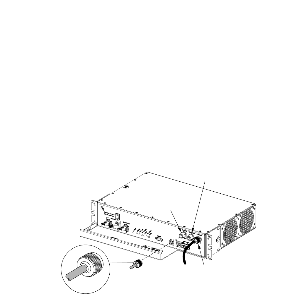
4. Connect the forward path cable to the FORWARD RF IN connector on the HU front
panel as shown in Figure 3-8.
Figure 3-8. Forward and Reverse Path Coaxial Cable Connections
5. Connect the reverse path cable to the REVERSE RF OUT connector on the HU front
panel (see Figure 3-8).
6. If the HU supports diversity, connect the diversity reverse path cable to the REVERSE 2
RF OUT connector on the HU front panel (see Figure 3-8).
7. Dress and secure cables at the HU.
8. Complete all remaining coaxial connections at the BTS interface as specified in the system
design plan.
16887-A
TYPE-N MALE
CONNECTOR
FORWARD RF IN
CONNECTOR
(FORWARD PATH)
REVERSE
RF OUT CONNECTOR
(REVERSE PATH)
REVERSE 2
RF OUT CONNECTOR
(DIVERSITY REVERSE PATH)

ADCP-75-126 • Issue B • April 2002 • Section 3: Host Unit Installation
Page 3-10
©2002, ADC Telecommunications, Inc.
7 OPTICAL CONNECTIONS
The optical interface between the HU and the RU is supported by either two (non-diversity) or
three (diversity) optical ports. Each optical port consists of an SC optical adapter which is
mounted on the HU front panel. Port 1provides the optical fiber connection for the forward path
(downlink) signal. Port 2provides the optical fiber connection for the reverse path (uplink)
signal. Port 3provides the optical fiber connection for the diversity reverse path (uplink) signal.
The optical connections are dependent on whether or not aWDM (optional accessory) is
installed. If the installation does not include aWDM, proceed to Section 7.1 for the optical
connections procedure. If the installation does include aWDM, proceed to Section 7.2 for the
optical connections procedure.
7.1 Optical Connections Without WDM
Use the following procedure to connect the optical fibers when aWDM is not installed with the
HU:
1. Obtain two (non-diversity) or three (diversity) patch cords that are of sufficient length to
reach from the HU to the fiber distribution panel.
2. Designate one of the patch cords as the forward path link and the other as the reverse
path link and attach an identification label or tag next to the connector. For diversity
systems, designate and label or tag athird patch cord as the diversity reverse path link.
3. Remove the dust caps from the HU optical ports and from the patch cord connectors that
will be connected to the HU.
4. Clean each patch cord connector (follow connector supplier’s recommendations) and then
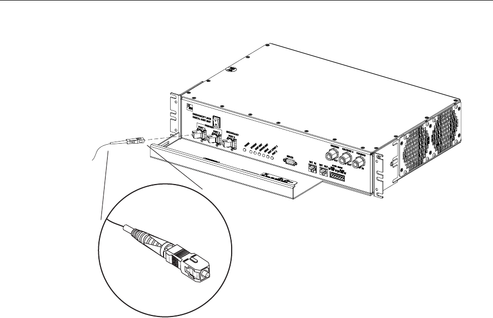
insert the connector into the appropriate optical port as shown in Figure 3-9 and as
specified by the following:
Port 1 - Forward path patch cord
Port 2 - Reverse path patch cord
Port 3 - Diversity reverse path patch cord
5. Route the patch cords from the HU to the fiber distribution panel.
Danger: This equipment uses aClass 1Laser according to FDA/CDRH rules. Laser radiation
can seriously damage the retina of the eye. Do not look into the ends of any optical fiber. Do not
look directly into the optical transmitter of any unit or exposure to laser radiation may result.
An optical power meter should be used to verify active fibers. Aprotective cap or hood MUST
be immediately placed over any radiating transmitter or optical fiber connector to avoid the
potential of dangerous amounts of radiation exposure. This practice also prevents dirt particles
from entering the connector.
Note: The HU optical adapters are angled to the left.Therefore, patch cords should always
be routed to the HU from the left side of the rack. Routing patch cords to the HU from the
right side of the rack may exceed the bend radius limitations for the optical fiber.
ADCP-75-126 • Issue B • April 2002 • Section 3: Host Unit Installation
Page 3-11
©2002, ADC Telecommunications, Inc.
Figure 3-9. Fiber Optic Cable Connections To Host Unit
6. Identify the OSP cable optical fiber terminations that correspond to the RU.
7. Designate one of the OSP fibers as the forward path link and the other as the reverse
path link and attach an identification label or tag next to the connector. For diversity
systems, designate and label or tag athird fiber as the diversity reverse path link.
8. Remove the dust caps from the OSP cable optical fiber adapters and from the patch cord connectors.
9. Clean each patch cord connector (follow connector supplier’s recommendations) and then
mate the connector with the appropriate OSP cable adapter.
10. Store any excess patch cord slack at the fiber distribution panel.
7.2 Optical Connections With WDM
Use the following procedure to connect the optical fibers when aWDM module is installed with
the HU:
1. Obtain apatch cord that is of sufficient length to reach from the WDM module to the fiber
distribution panel.
2. Remove the dust cap from one of the two optical ports on the WDM module and from the
patch cord connector that will be connected to the WDM module.
16893-A
ADCP-75-126 • Issue B • April 2002 • Section 3: Host Unit Installation
Page 3-12
©2002, ADC Telecommunications, Inc.
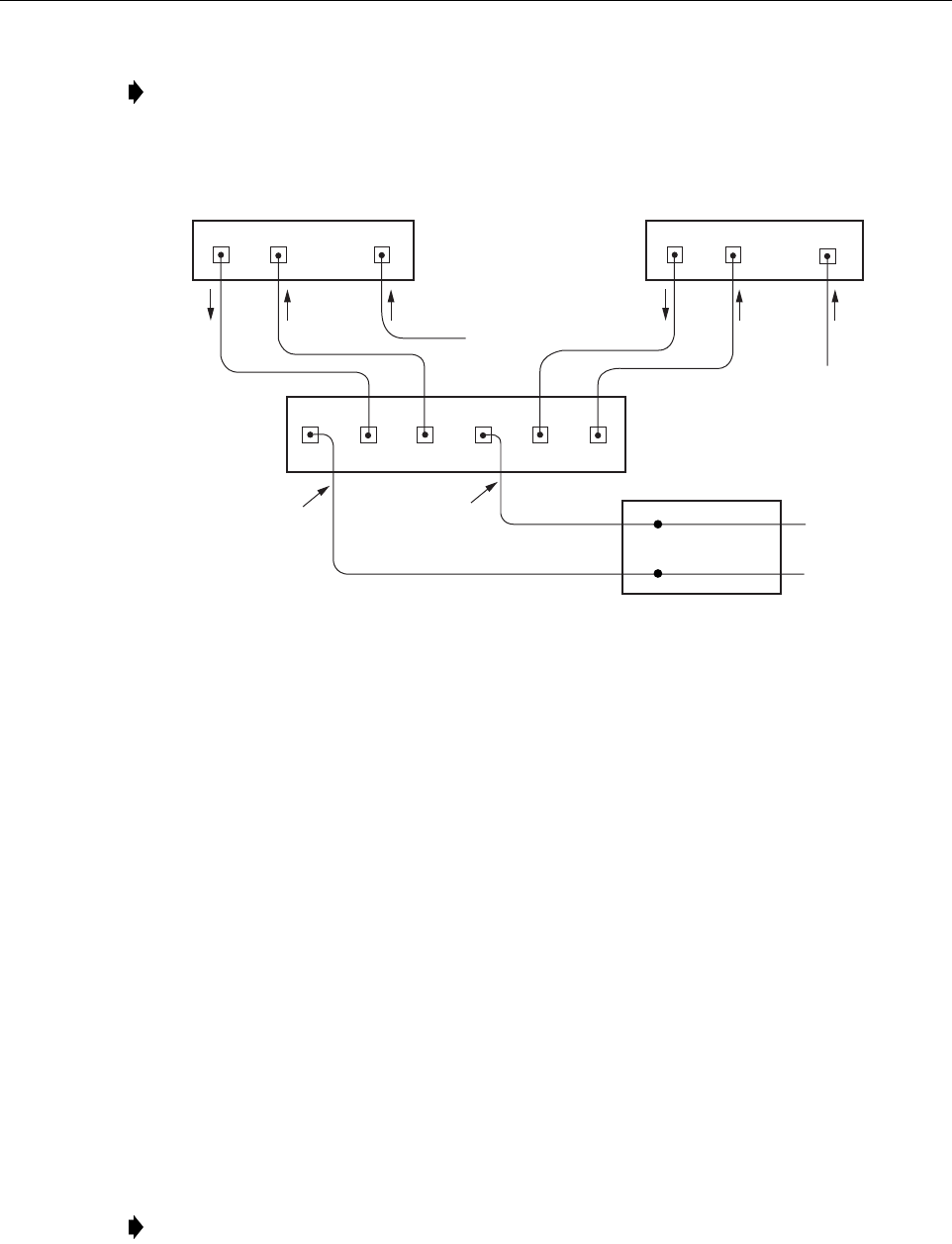
Figure 3-10. Fiber Optic Connections To WDM Module
3. Clean the patch cord connector (follow connector supplier’s recommendations) and then
insert the connector into one of the WDM module’s optical ports (port 1or 4).
4. Route the patch cord from the WDM to the fiber distribution panel.
5. Identify the OSP cable optical fiber termination that corresponds to the RU.
6. Remove the dust cap from the OSP cable optical adapter and from the patch cord
connector.
7. Clean the patch cord connector (follow connector supplier’s recommendations) and then
mate the connector with the appropriate OSP cable adapter.
8. Store any excess patch cord slack at the fiber distribution panel.
9. Remove the dust caps from the HU optical ports and from the WDM pigtails that will be
connected to the HU.
10. Clean each pigtail connector (follow connector supplier’s recommendations) and then
insert the connector into the appropriate optical port on the HU as shown in Figure 3-9 and
as diagramed in Figure 3-10.
Note: Each WDM module can support two separate HU’s. The WDM module ports are
numbered from 1through 6as shown in Figure 3-10.Ports 1through 3are used for HU #1
and Ports 4through 6are used for HU #2.
Note: The HU optical adapters are angled to the left.Therefore, pigtails should always be
routed to the HU from the left side of the rack. Routing pigtails to the HU from the right
side of the rack may exceed the bend radius limitations for the optical fiber.
PORT 1 PORT 2
HOST UNIT 1 HOST UNIT 2
PORT 1 PORT 2
PORT 3
PORT 3
16892-B
REVERSE
PATH
REVERSE
PATH
FORWARD
PATH
FORWARD
PATH
WAVELENGTH DIVISION
MULTIPLEXER
OSP CABLE
OPTICAL FIBERS
HOST UNIT 1
(BI-DIRECTIONAL FIBER
LINK WITH REMOTE UNIT)
HOST UNIT 2
(BI-DIRECTIONAL FIBER
LINK WITH REMOTE UNIT)
FIBER DISTRIBUTION
PANEL (FDP)
X
X
123 45 6
DIVERSITY
REVERSE PATH
DIVERSITY
REVERSE PATH
TO FDP
TO FDP
ADCP-75-126 • Issue B • April 2002 • Section 3: Host Unit Installation
Page 3-13
©2002, ADC Telecommunications, Inc.
8 CONTROLLER AREA NETWORK CONNECTIONS
Controller area Network (CAN) interface connections between multiple HU’s are supported by
apair of RJ-45 jacks. One of the jacks is designated as the NET IN port and the other jack is
designated as the NET OUT port. The CAN interface allows up to 24 HU’s to be connected
together (in daisy-chain fashion) and controlled through asingle Digivance EMS computer. A
one meter long cable is provided with each HU for CAN connections. Use the following
procedure to connect CAN interface cables between multiple HU’s:
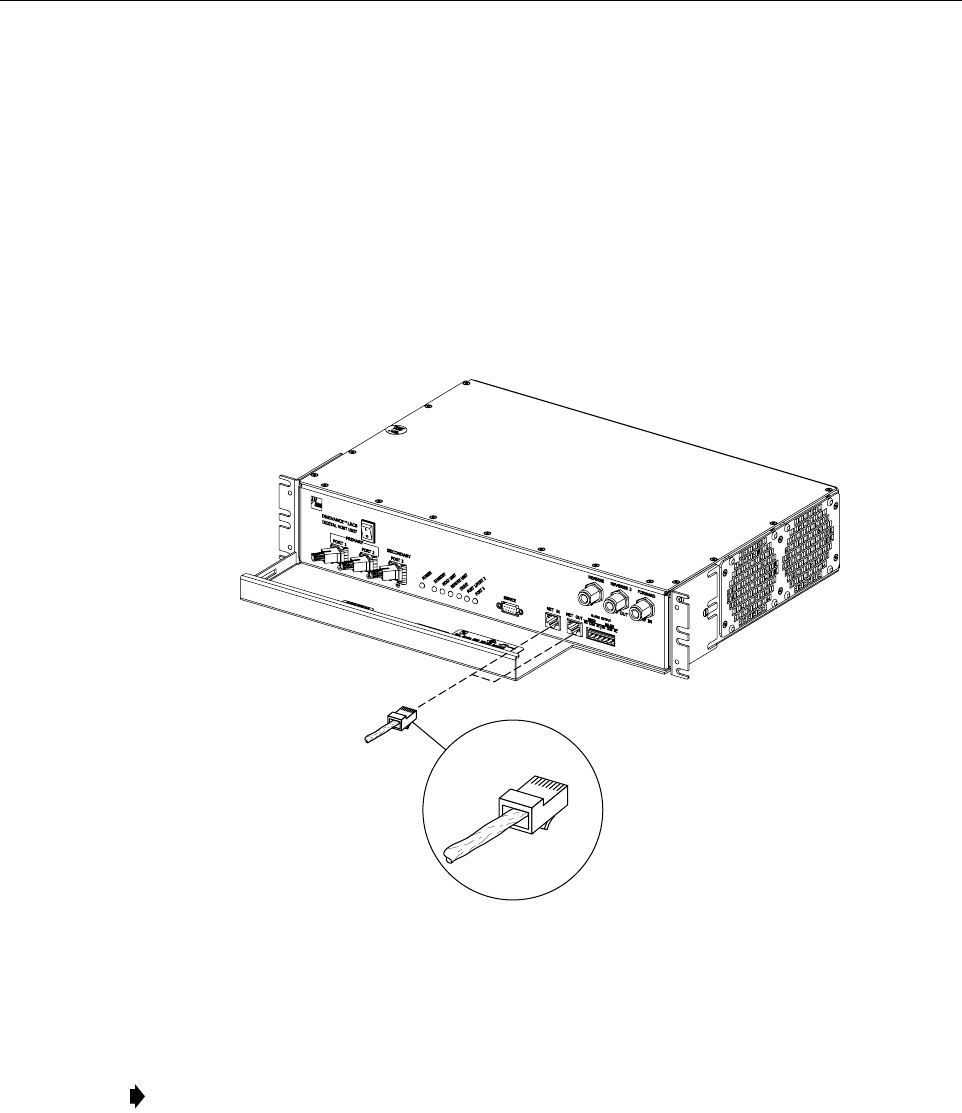
1. Connect one end of the CAN interface cable (provided with the HU) to either the NET IN
or NET OUT port on HU #1 as shown in Figure 3-11.
Figure 3-11. Controller Area Network Connections
2. Route the CAN interface cable to HU #2 and connect the cable’s free end to the port that is
the logical opposite of the network port the cable was connected to at HU #1.
3. If athird HU will be connected to the network, connect asecond CAN interface cable to
the remaining network port on HU #2.
4. Route the second CAN interface cable to HU #3 and connect the cable’s free end to the
port that is the logical opposite of the port that the cable is connected to at HU #2.
5. Repeat steps 3and 4for each additional HU that is added to the network up to atotal of 24
HU’s. Adiagram of typical CAN interface connections is shown in Figure 3-12.
Note: If connected to aNET OUT port at HU #1, connect to the NET IN port at HU #2. If
connected to aNET IN port at HU #1, connect to aNet OUT port at HU #2.
16901-A
RJ-45 CONNECTOR
DETAIL
ADCP-75-126 • Issue B • April 2002 • Section 3: Host Unit Installation
Page 3-14
©2002, ADC Telecommunications, Inc.
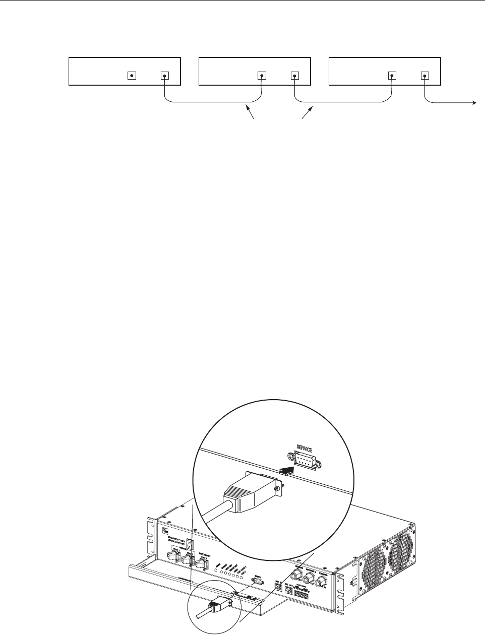
Figure 3-12. Configuring CAN Connections with Multiple Host Units
9 SERVICE INTERFACE CONNECTION
The service interface connection between the HU and the Digivance EMS computer is
supported by asingle DB-9 female connector. The service connector provides an RS-232 DTE
interface. Athree meter long straight-through RS-232 interface cable is provided with the HU
for connecting the EMS computer to the HU. Use the following procedure to install the service
interface cable:
1. Connect one end of the service interface cable (provided with HU) to the SERVICE port as
shown in Figure 3-13.
2. Route the service interface cable to the EMS computer and connect the free end of the
cable to the computer’s RS-232 DCE port. Refer to the user manual provided with the
computer to locate the required port.
Figure 3-13. Service Interface Connection
HOST UNIT 1 HOST UNIT 2 HOST UNIT 3
NET IN NET OUT NET IN NET OUT NET IN NET OUT
16900-A
CONTROLLER AREA NETWORK
INTERFACE CABLES
TO NEXT HOST UNIT
16890-A
ADCP-75-126 • Issue B • April 2002 • Section 3: Host Unit Installation
Page 3-15
©2002, ADC Telecommunications, Inc.
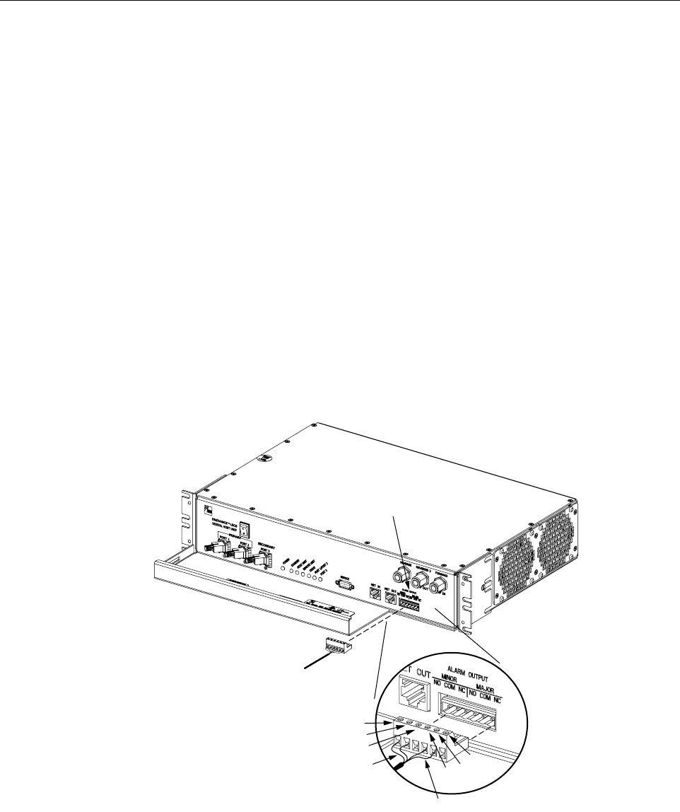
10 EXTERNAL ALARM SYSTEM CONNECTIONS
The alarm interface between the HU and an external alarm system is supported by asix-terminal
plug (with screw-type terminals) that connects to areceptacle mounted on the HU front panel.
The terminal plug provides connections to normally open (NO) and normally closed (NC) dry
type alarm contacts for both major and minor alarms. Acategory 3or 5cable is typically used to
connect the HU to the external alarm system. Use the following procedure to install the alarm
wiring and connect it to the HU:
1. Obtain the required length of category 3or 5cable.
2. Route the cable between the HU and the external alarm system (if not already routed) and
then cut to the required length. Allow sufficient slack for dressing and organizing the cable
at the HU.
3. Strip back the outer cable sheath and insulation to expose the wires at both ends of the
cable and strip back 0.2 inches (5 mm) of insulation from each wire.
4. Connect the Major alarm wire pair to the MAJOR COM/NC or MAJOR COM/NO
terminals (whichever is required by the external alarm system) on the HU alarm terminal
connector (supplied with HU) as shown in Figure 3-14.
Figure 3-14. External Alarm System Connections
5. Connect the Minor alarm wire pair to the MINOR COM/NC or MINOR COM/NO
terminals (whichever is required by the external alarm system) on the HU alarm terminal
connector (see Figure 3-14).
16884-B
ALARM
CONNECTOR
MAJOR ALARM WIRES
MINOR ALARM WIRES
ALARM CONNECTOR
DETAIL
NO
COM
NC
NO COM
NC
ADCP-75-126 • Issue B • April 2002 • Section 3: Host Unit Installation
Page 3-16
©2002, ADC Telecommunications, Inc.
6. Connect the Major and Minor alarm wire pairs to the appropriate terminals on the external
alarm system.
7. Dress and secure cable per standard industry practice.
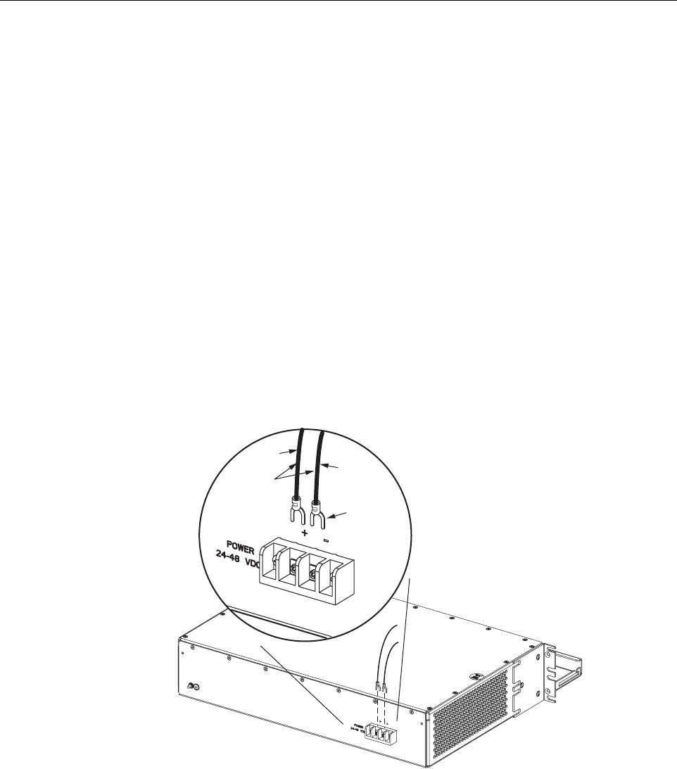
11 DC POWER CONNECTIONS
The HU is powered by ±24 or ±48 Vdc power. The power is fed to the HU through ascrew-
down type terminal strip located on the rear side of the unit. Power to the HU must be supplied
through afuse panel such as the 20 position PowerWorx fuse panel (available separately) and
the power must be protected with a 3 Amp GMT fuse. Use the following procedure to install the
power wiring:
1. Obtain one pair of #18 AWG (1.00 mm) red and black insulated copper wire for use as the
power wiring.
2. Terminate one end of each wire with afork terminal as shown in Figure 3-15.
3. Connect the power wires to the power terminal strip at the rear of the HU.
Figure 3-15. DC Power Connections
4. Route the free ends of the wires to the fuse panel and locate the terminals that will be used
for the power feed. Refer to the user manual provided with the fuse panel for specific
information.
5. Remove the fuse from the circuit that will power the HU.
FORK
TERMINALS
#18 AWG
(1.0mm)
COPPER
WIRE
+ (RED)
– (BLACK)
16891-A

ADCP-75-126 • Issue B • April 2002 • Section 3: Host Unit Installation
Page 3-17
©2002, ADC Telecommunications, Inc.
6. Connect the power wires to the appropriate terminals as specified in the fuse panel user
manual.
7. Dress and secure the power wiring at the fuse panel and the HU. The procedure for
checking the voltage level and verifying that the HU is ready to power up is provided in
SECTION 4: OPERATION.

ADCP-75-126 • Issue B • April 2002 • Section 3: Host Unit Installation
Page 3-18
©2002, ADC Telecommunications, Inc.
Blank

ADCP-75-126 • Issue B • April 2002 • Section 4: Operation
Page 4-1
©2002, ADC Telecommunications, Inc.
SECTION 4: OPERATION
1 BEFORE STARTING OPERATION . . . . . . . . . . . . . . . . . . . . . . . . . . . . . . . . . . . . . . . . . . . . . . . . . . . . . . . . . . . .4-1
1.1 Tools and Materials . . . . . . . . . . . . . . . . . . . . . . . . . . . . . . . . . . . . . . . . . . . . . . . . . . . . . . . . . . . . . . .4-1
1.2 Readiness Check. . . . . . . . . . . . . . . . . . . . . . . . . . . . . . . . . . . . . . . . . . . . . . . . . . . . . . . . . . . . . . . . .4-2
2 TURN-UP SYSTEM AND VERIFY OPERATION . . . . . . . . . . . . . . . . . . . . . . . . . . . . . . . . . . . . . . . . . . . . . . . . . . . .4-2
2.1 Turn-Up Procedure. . . . . . . . . . . . . . . . . . . . . . . . . . . . . . . . . . . . . . . . . . . . . . . . . . . . . . . . . . . . . . . .4-3
2.2 Download HU and RU System Software . . . . . . . . . . . . . . . . . . . . . . . . . . . . . . . . . . . . . . . . . . . . . . . . .4-6
2.3 Determine Forward Path Input Signal Level . . . . . . . . . . . . . . . . . . . . . . . . . . . . . . . . . . . . . . . . . . . . . .4-7
2.4 Enter Site Name and Site Number . . . . . . . . . . . . . . . . . . . . . . . . . . . . . . . . . . . . . . . . . . . . . . . . . . . . 4-10
2.5 Enter Host Forward Attenuation . . . . . . . . . . . . . . . . . . . . . . . . . . . . . . . . . . . . . . . . . . . . . . . . . . . . . . 4-11
2.6 Determine Output Signal Level at STM Antenna Port . . . . . . . . . . . . . . . . . . . . . . . . . . . . . . . . . . . . . . . 4-12
2.7 Enter Remote Forward Attenuation. . . . . . . . . . . . . . . . . . . . . . . . . . . . . . . . . . . . . . . . . . . . . . . . . . . . 4-13
2.8 Enter Host Reverse Attenuation . . . . . . . . . . . . . . . . . . . . . . . . . . . . . . . . . . . . . . . . . . . . . . . . . . . . . . 4-15
2.9 Enter Host Forward and Reverse Delay . . . . . . . . . . . . . . . . . . . . . . . . . . . . . . . . . . . . . . . . . . . . . . . . . 4-17
_________________________________________________________________________________________________________
1 BEFORE STARTING OPERATION
This section provides guidelines for turning-up the Digivance LRCS, verifying that all units are
operating properly, testing to ensure that all performance requirements are satisfied, and
correcting any installation problems. This process assumes that the various units have been
installed in accordance with the system design plan.
1.1 Tools and Materials
The following tools and materials are required in order to complete the procedures in this
section:
• Portable spectrum analyzer or RF power meter
•AC/DCvoltmeter
• External attenuators (if specified in system design plan)
• PC-type computer with Digivance Element Management System (EMS) software installed
• Straight-through RS-232 DB-9 interface cable (ADC part #1192835)
• Handset
• Pencil or pen
• Writing pad
Content Page

ADCP-75-126 • Issue B • April 2002 • Section 4: Operation
Page 4-2
©2002, ADC Telecommunications, Inc.
1.2 Readiness Check
Before starting the turn-up process, inspect the complete LRCS system to verify that all
components of the system are ready to be powered-up. This will ensure that no units of the
system will be damaged during turn-up and that all existing systems will continue to function
properly.
1.2.1 Host Unit Installation Checks
Complete the following checks at the HU prior to starting the turn-up process:
1. Verify that the ON/OFF switch on the HU is in the OFF position (press O).
2. At the fuse panel, install a 3 Amp GMT fuse in the circuit that supplies DC power to the HU.
3. Using aDC voltmeter, verify that the DC voltage level at the HU power terminals is
between ±24 or ±48 Vdc (can be either polarity).
4. Verify that all electrical and optical connections have been completed and that all optical
fibers, coaxial cables, and wires are properly routed and secured.
1.2.2 Remote Unit Installation Checks
Complete the following checks at the RU prior to starting the turn-up process:
1. Verify that the ON/OFF switch on the STM is in the OFF position (press O).
2. Verify that the RF ON/OF switch on the LPA in the OFF position.
3. At the AC breaker box, close the circuit breaker for the circuit that supplies AC power to
the RU.
4. Using an AC voltmeter, verify that the AC voltage level at the AC outlet is between 110
and 120 Vac (for 120 Vac powered systems) or between 220 and 240 Vac (for 240 Vac
powered systems).
5. Verify that all electrical and optical connections have been completed and that all optical
fibers, coaxial cables, and wires are properly routed and secured.
2 TURN-UP SYSTEM AND VERIFY OPERATION
The process of turning-up the system and verifying operation involves powering up the various
system components, verifying that the LED indicators show normal operation, setting the site
number and name, adjusting the RF signal levels, and adjusting the path delay.