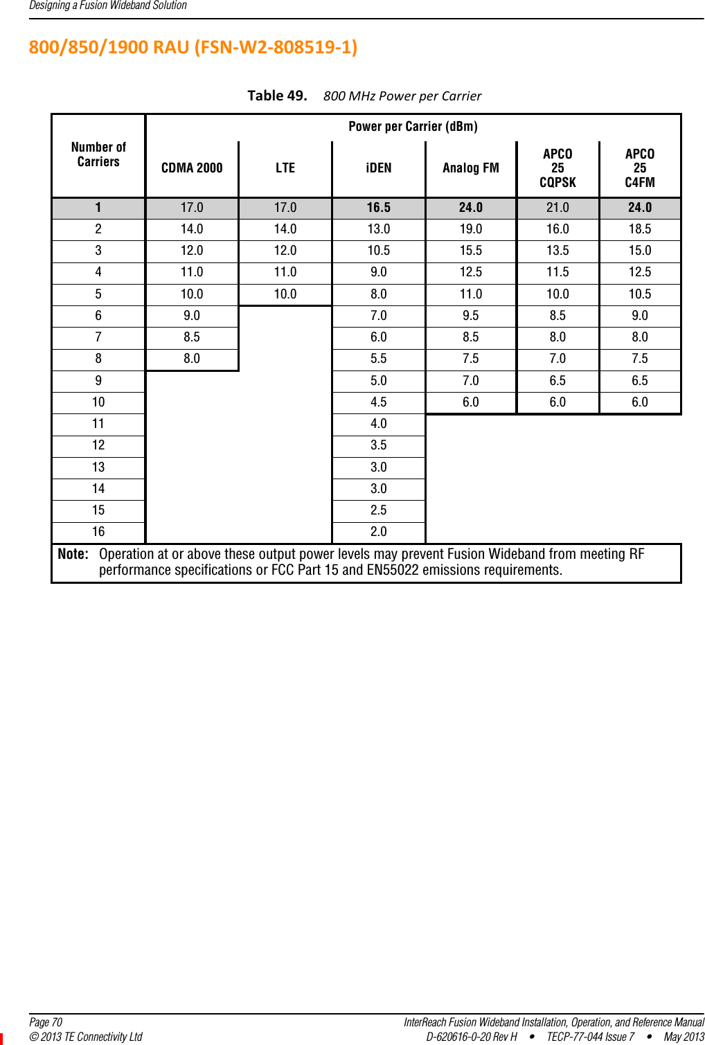
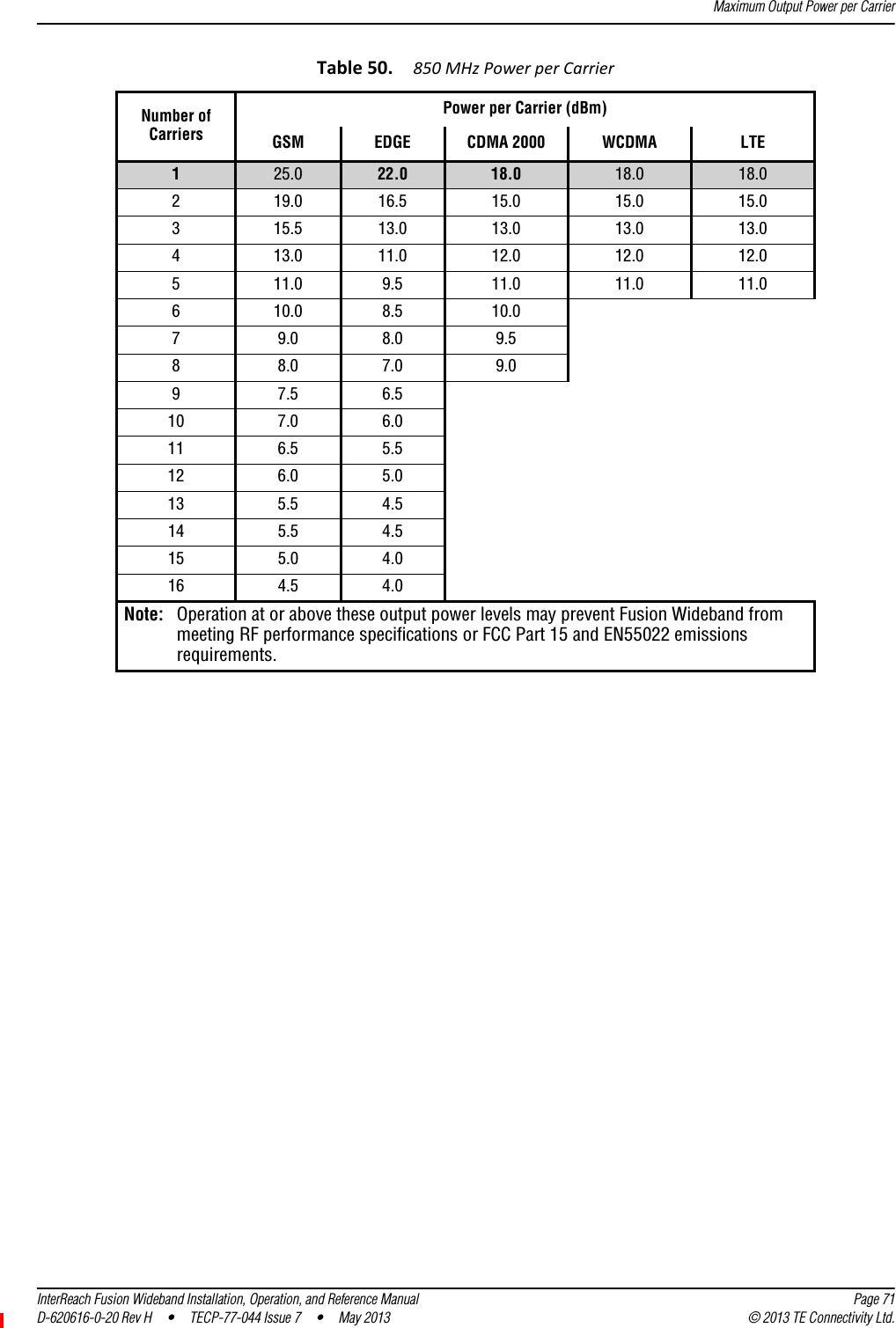
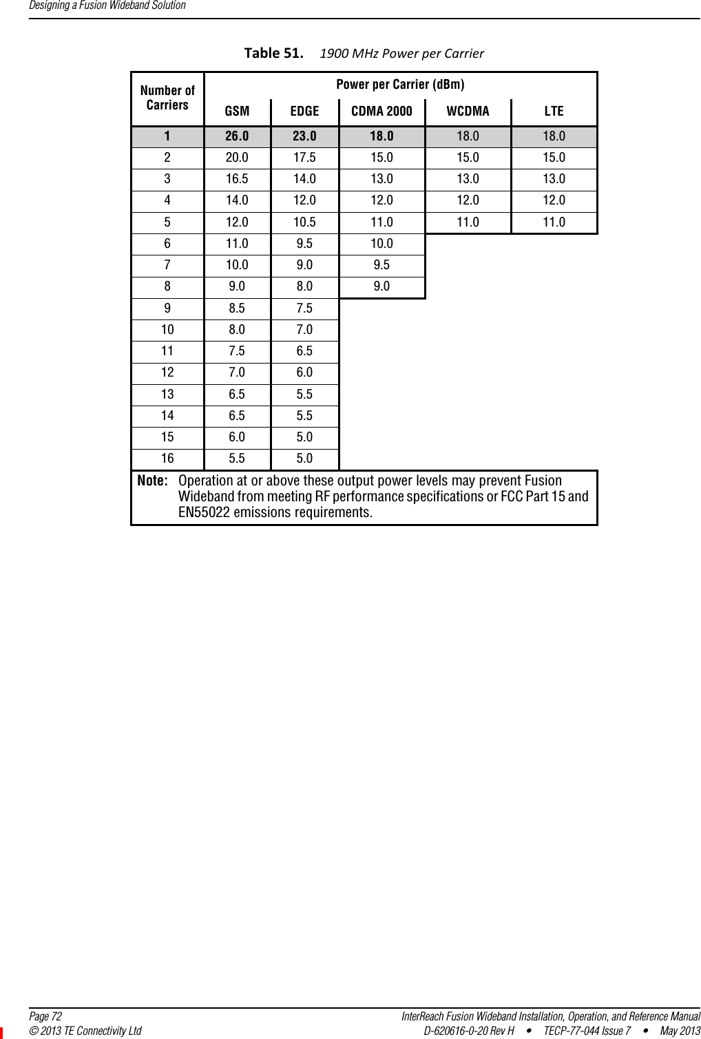
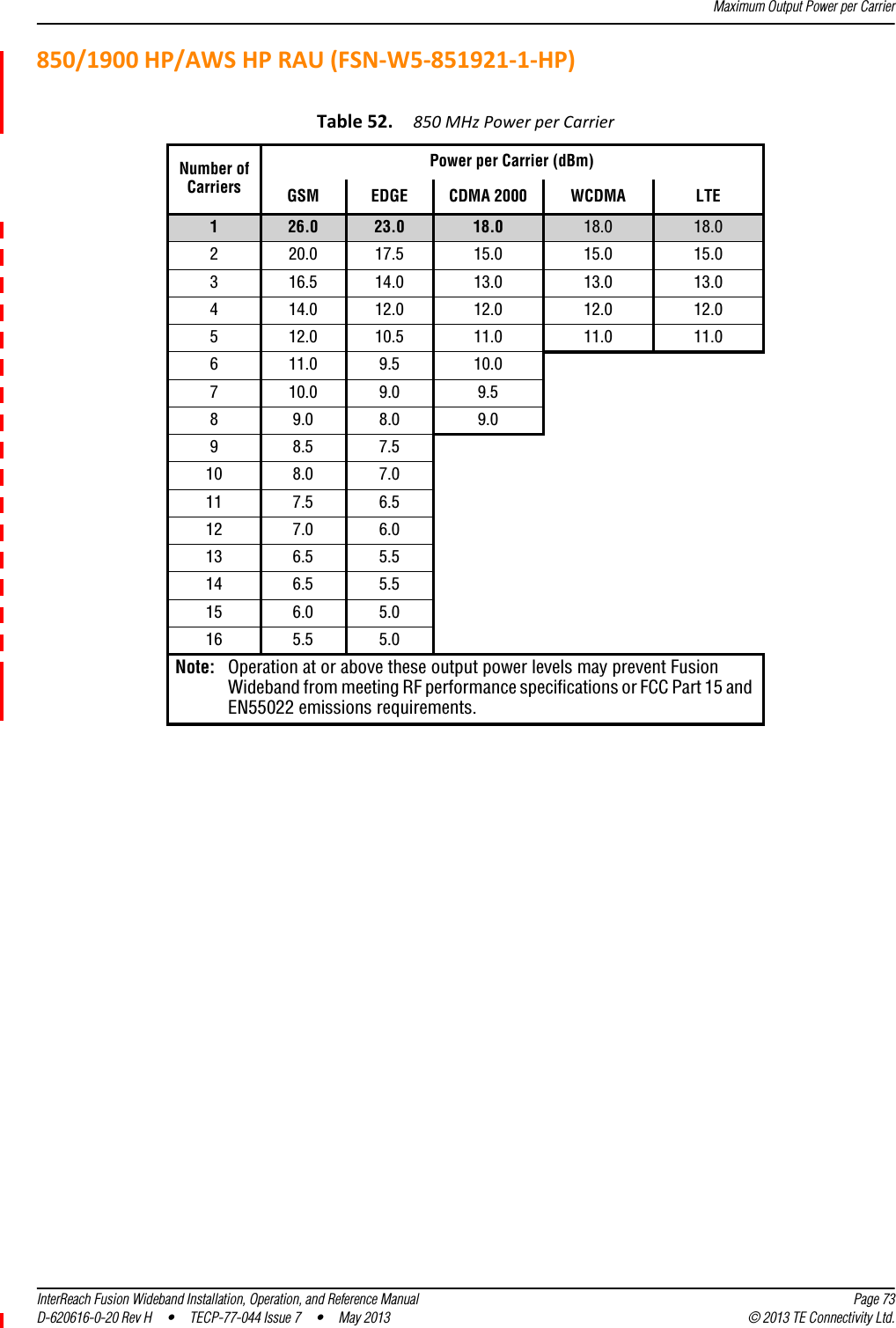
ADC Telecommunications F0674-011 Tri-Band Remote Antenna Unit User Manual 77044p7

ADC Telecommunications Inc. Tri-Band Remote Antenna Unit 77044p7

Contents

Users Manual Part I

TECP-77-044 · Issue 7 · May 2013D-620616-0-20 Rev HInterReach Fusion® WidebandInstallation, Operation, and Reference Manual
Copyright©2013TEConnectivity,Inc.AllRightsReserved.InformationcontainedinthisdocumentiscompanyprivatetoTEConnectivityLtd.,andshallnotbemodified,used,copied,reproducedordisclosedinwholeorinpartwithoutthewrittenconsentofTE.Trademark InformationFlexWave,FlexWavePrism,InterReachSpectrum,InterReachUnison,UniversalRadioHead,TEConnectivity,andTEconnectivity(logo)aretrademarks.All other logos, products and/orcompany names referred to herein might be trademarks of their respectiveowners.Disclaimer of LiabilityTEisaregisteredtrademarkandInterReach,InterReachUnison,InterReachFusion,WAVEXchange,FlexWaveareregisteredtrademarksandtrademarksofTEConnectivity.Allotherproducts,companynames,servicemarks,andtrademarksmentionedinthisdocumentorwebsiteareusedforidentificationpurposesonlyandmaybeownedbyothercompanies.REVISION HISTORYLIST OF CHANGESThe technical changes incorporated into this issue are listed below.ISSUE DATE REASON FOR CHANGE1 7/2008 First release2 10/2008 Add Fusion Wideband 1900/AWS product content3 8/2009 Add Fusion Wideband 700/AWS  and 700 MIMO product content4 5/2010 Add Fusion Wideband 700 (Lower ABC) MIMO product content5 9/2011 Add Fusion Wideband 2600 MIMO product content6 11/2012 Add Fusion Wideband 700 ABC/AWS HP/AWS HP and Fusion Wideband 700 UC/AWS HP/AWS HP product content7 4/2013 Add Fusion Wideband 2100 HP/1800 HP and Fusion Wideband 850/1900 HP/AWP HP product contentPAGE IDENTIFIER DESCRIPTION OF CHANGEAdd Fusion Wideband 2100 HP/1800 HP and Fusion Wideband 850/1900 HP/AWP HP product content
InterReach Fusion Wideband Installation, Operation, and Reference Manual Page iiiD-620616-0-20 Rev H • TECP-77-044 Issue 7  •  May 2013 ©2013 TE Connectivity Ltd.TABLEOFCONTENTSPreface ______________________________________________________________________ 1PurposeandScope .................................................................................................................................................................. 2TECustomerPortal .................................................................................................................................................................. 3ConventionsinthisManual ..................................................................................................................................................... 4Measurements ...........................................................................................................................................................................4DocumentCautionsandNotes...................................................................................................................................................4DocumentFonts .........................................................................................................................................................................4StandardsConformance........................................................................................................................................................... 5RelatedPublications ................................................................................................................................................................ 6InterReachFusionWidebandSystemDescription ____________________________________ 7SystemOverview ..................................................................................................................................................................... 8SystemHardwareDescription................................................................................................................................................ 10SystemOA&MCapabilitiesOverview..................................................................................................................................... 12SystemMonitoringandReporting ...........................................................................................................................................13UsingAlarmContacts ...............................................................................................................................................................14SystemConnectivity .............................................................................................................................................................. 15SystemOperation .................................................................................................................................................................. 16SystemSpecifications ............................................................................................................................................................ 17RFEnd‐to‐EndPerformance ................................................................................................................................................... 202100/1800RAU(FSN‐W1‐2118‐1)............................................................................................................................................202100HP/1800HP(FSN‐W1‐2118‐1‐HP)...................................................................................................................................212100HighPowerRAU(FSN‐W1‐21HP‐1) .................................................................................................................................221900/AWSRAU(FSN‐W1‐1921‐1)............................................................................................................................................22800/850/1900RAU(FSN‐W2‐808519‐1) ..................................................................................................................................23700/AWSRAU(FSN‐W2‐7021‐1) ..............................................................................................................................................24700/700(UpperC)MIMORAU(FSN‐W2‐7575‐1)....................................................................................................................25700/700(LowerABC)MIMORAU(FSN‐W2‐7070‐1)................................................................................................................25700ABC/AWSHP/AWSHPRAU(FSN‐W4‐702121‐1‐HP).........................................................................................................25700UC/AWSHP/AWSHPRAU(FSN‐W4‐752121‐1‐HP)...........................................................................................................26850/1900HP/AWSHPRAU(FSN‐W5‐851921‐1‐HP)................................................................................................................272500/2500RAU(FSN‐2500‐2‐WMAX)......................................................................................................................................282600/2600RAU(FSN‐W3‐2626‐1)............................................................................................................................................28FusionWidebandMainHub ____________________________________________________ 29FusionWidebandMainHubOverview ................................................................................................................................... 30FusionWidebandMainHubFrontPanel ................................................................................................................................ 32OpticalFiberUplink/DownlinkPorts ........................................................................................................................................33CommunicationsRS‐232SerialConnector ...............................................................................................................................33MainHubLEDIndicators ..........................................................................................................................................................33UnitStatusLEDs................................................................................................................................................................34FiberPortLEDs .................................................................................................................................................................34FusionWidebandMainHubRearPanel...................................................................................................................................35FusionWidebandMainHubRearPanelConnectors........................................................................................................369‐pinD‐subConnector..............................................................................................................................................36N‐typeFemaleConnectors .......................................................................................................................................36MainHubSpecifications ........................................................................................................................................................ 37Faults,Warnings,andStatusMessages.................................................................................................................................. 38Events .......................................................................................................................................................................................38ViewPreference .......................................................................................................................................................................38
Table of Contents  Page iv InterReach Fusion Wideband Installation, Operation, and Reference Manual© 2013 TE Connectivity Ltd D-620616-0-20 Rev H  •  TECP-77-044 Issue 7  •  May 2013FusionWidebandExpansionHub ________________________________________________ 41ExpansionHubOverview ....................................................................................................................................................... 42ExpansionHubFrontPanel ......................................................................................................................................................4475OhmTypeFConnectors ......................................................................................................................................................45ManufacturingRS‐232SerialConnector ..................................................................................................................................45ConsolePort ..................................................................................................................................................................... 45LocalMonitoring .............................................................................................................................................................. 45OpticalFiberUplink/DownlinkConnectors .............................................................................................................................. 45LEDIndicators........................................................................................................................................................................... 46UnitStatusandDL/ULStatusLEDs................................................................................................................................... 46RJ‐45PortLEDs ................................................................................................................................................................. 48ExpansionHubRearPanel ..................................................................................................................................................... 49Faults,Warnings,andStatusMessages.................................................................................................................................. 50ExpansionHubSpecifications................................................................................................................................................. 51RemoteAccessUnit ___________________________________________________________ 53Overview ............................................................................................................................................................................... 54RemoteAccessUnitConnectors............................................................................................................................................. 5750OhmType‐NConnector....................................................................................................................................................... 5775OhmType‐FConnector ....................................................................................................................................................... 57RAULEDIndicators ................................................................................................................................................................ 58StatusLEDs ............................................................................................................................................................................... 58FaultsandWarnings .............................................................................................................................................................. 59RemoteAccessUnitSpecifications......................................................................................................................................... 60DesigningaFusionWidebandSolution ___________________________________________ 61Overview ............................................................................................................................................................................... 62DownlinkRSSIDesignGoal .................................................................................................................................................... 64MaximumOutputPowerperCarrier...................................................................................................................................... 65700/AWSRAU(FSN‐W2‐7021‐1)..............................................................................................................................................65700MHz(UpperC)MIMORAU(FSN‐W2‐7575‐1) ................................................................................................................... 67700MHz(LowerABC)MIMORAU(FSN‐W2‐7070‐1)............................................................................................................... 67700ABC/AWSHP/AWSHPRAU(FSN‐W4‐702121‐1‐HP)......................................................................................................... 68700UC/AWSHP/AWSHPRAU(FSN‐W4‐752121‐1‐HP) .......................................................................................................... 69800/850/1900RAU(FSN‐W2‐808519‐1).................................................................................................................................. 70850/1900HP/AWSHPRAU(FSN‐W5‐851921‐1‐HP)................................................................................................................ 731900/AWSRAU(FSN‐W1‐1921‐1)............................................................................................................................................ 752100/1800RAU(FSN‐W1‐2118‐1) ........................................................................................................................................... 772100HP/1800HPRAU(FSN‐W1‐2118‐1‐HP)........................................................................................................................... 782100HighPowerRAU(FSN‐W1‐21HP‐1) ................................................................................................................................. 792500/2500WiMAXRAU(FSN‐2500‐2‐WMAX)......................................................................................................................... 792600MHzMIMORAU(FSN‐W3‐2626‐1) ................................................................................................................................. 79DesigningforCapacityGrowth................................................................................................................................................. 80SystemGain........................................................................................................................................................................... 81EstimatingRFCoverage.......................................................................................................................................................... 82Equation1................................................................................................................................................................................ 82Equation2—PathLossEquation ..............................................................................................................................................83RAUCoverageDistance ............................................................................................................................................................ 84Equation3................................................................................................................................................................................ 84Equation4—PathLossEquation ..............................................................................................................................................85ExampleDesignEstimateforan1900MHzCDMAApplication ............................................................................................... 87LinkBudgetAnalysis .............................................................................................................................................................. 89ElementsofaLinkBudgetforNarrowbandStandards ............................................................................................................ 89NarrowbandLinkBudgetAnalysisforaMicrocellApplication ................................................................................................ 91ElementsofaLinkBudgetforCDMAStandards ...................................................................................................................... 93OtherCDMAIssues................................................................................................................................................................... 95CDMALinkBudgetAnalysisforaMicrocellApplication .......................................................................................................... 96ConsiderationsforRe‐Radiation(Over‐the‐Air)Systems ......................................................................................................... 99
Table of ContentsInterReach Fusion Wideband Installation, Operation, and Reference Manual Page vD-620616-0-20 Rev H • TECP-77-044 Issue 7  •  May 2013 © 2013 TE Connectivity Ltd.OpticalPowerBudget .......................................................................................................................................................... 100ConnectingaMainHubtoaBaseStation............................................................................................................................. 101UplinkAttenuation .................................................................................................................................................................102RAUAttenuationandALC.......................................................................................................................................................102UsingtheRAU10dBAttenuationSetting ......................................................................................................................103UsingtheUplinkALCSetting ..........................................................................................................................................104InstallingFusionWideband ____________________________________________________ 105InstallationRequirements.................................................................................................................................................... 107ComponentLocationRequirements.......................................................................................................................................107CableandConnectorRequirements.......................................................................................................................................107DistanceRequirements ..........................................................................................................................................................108SafetyPrecautions ............................................................................................................................................................... 109InstallationGuidelines............................................................................................................................................................109GeneralSafetyPrecautions ....................................................................................................................................................109FiberPortSafetyPrecautions .................................................................................................................................................110PreparingforSystemInstallation ......................................................................................................................................... 111Pre‐InstallationInspection .....................................................................................................................................................111InstallationChecklist...............................................................................................................................................................111ToolsandMaterialsRequired.................................................................................................................................................113OptionalAccessories ..............................................................................................................................................................114InstallingaFusionWidebandMainHub ............................................................................................................................... 115InstallingaFusionWidebandMainHubinaRack..................................................................................................................115InstallinganOptionalCableManagerintheRack..................................................................................................................116InstallingaMainHubUsingthe12”Wall‐MountedRack(PN4712) .....................................................................................116InstallingaFusionWidebandMainHubDirectlytotheWall.................................................................................................117ConnectingtheFiberCablestotheMainHub .......................................................................................................................118PreparingtheFiberCables .............................................................................................................................................118CleaningtheFiberPorts .................................................................................................................................................118UsingCompressedAir.............................................................................................................................................118UsingIsopropylAlcohol ..........................................................................................................................................118CleaningtheFiberEnds ..................................................................................................................................................119TestingtheFiberCables .................................................................................................................................................119ConnectingtheFiberCables...........................................................................................................................................119Ifthefiberjumperislabeledwith1or2...................................................................................................................119IftheFiberJumperisColor‐Coded .........................................................................................................................120MakingPowerConnections....................................................................................................................................................120ACPoweredMainHub ...................................................................................................................................................120DCPoweredMainHubandExpansionHub....................................................................................................................120OptionalConnectiontoDCPowerSource..............................................................................................................................124PoweringontheMainHub....................................................................................................................................................126InstallingExpansionHubs .................................................................................................................................................... 127InstallinganExpansionHubinaRack ....................................................................................................................................127InstallinganExpansionHubUsingthe12”Wall‐MountedRack ............................................................................................127InstallinganExpansionHubDirectlytotheWall ...................................................................................................................128InstallinganOptionalCableManagerintheRack..................................................................................................................129PoweringontheExpansionHub ............................................................................................................................................129ConnectingtheFiberCablestotheExpansionHub ...............................................................................................................130PreparingtheFiberCables .............................................................................................................................................130ConnectingtheFiberCables...........................................................................................................................................130IftheFiberJumperIsLabeledwith1or2.................................................................................................................130IftheFiberJumperIsColor‐Coded .........................................................................................................................131Connectingthe75OhmCATVCables.....................................................................................................................................131TroubleshootingExpansionHubLEDsDuringInstallation .....................................................................................................132
Table of Contents  Page vi InterReach Fusion Wideband Installation, Operation, and Reference Manual© 2013 TE Connectivity Ltd D-620616-0-20 Rev H  •  TECP-77-044 Issue 7  •  May 2013InstallingRAUs..................................................................................................................................................................... 133InstallingRAUs........................................................................................................................................................................133InstallingPassiveAntennas ....................................................................................................................................................133Location ..........................................................................................................................................................................133800/850MHzIsolationRequirements ...........................................................................................................................134800MHziDENDownlinkand850MHzCellularUplink ..................................................................................................135850MHzCellularDownlinkand900MHziDENUplink .................................................................................................. 135ConnectingtheAntennatotheRAU ......................................................................................................................................135ConnectingtheCATVCable....................................................................................................................................................136TroubleshootingUsingRAULEDsDuringInstallation ............................................................................................................137ConfiguringtheFusionWidebandSystem ............................................................................................................................ 138ConnectingthePCtotheMainHubtoRunAdminBrowser ..................................................................................................138ProgrammingtheMainHubUsingAdminBrowser ................................................................................................................139UsingAdminBrowser..............................................................................................................................................................140SplicingFiberOpticCable..................................................................................................................................................... 145FusionWidebandSplicingofFiberandPigtail .......................................................................................................................145OptionA:FusionWidebandSplicetheFiber‐OpticCabletotheSC/APCPigtail............................................................145OptionB:FusionWidebandSplicetheFiber‐OpticCabletotheSC/APCPigtail ............................................................146InterfacingtheFusionWidebandMainHubtoanRFSource ................................................................................................ 147ConnectingaSingleFusionWidebandMainHubtoanRFSource ........................................................................................147ConnectingaFusionWidebandMainHubtoanIn‐BuildingBTS...........................................................................................147ConnectingaSimplexBaseStationtoaFusionWidebandMainHubRFBand..............................................................148ConnectingaDuplexBaseStationtoaFusionWidebandMainHub ............................................................................. 149ConnectingaFusionWidebandMainHubRFBandtoMultipleBTSs....................................................................................150ConnectingaFusionWidebandMainHubtoaRoof‐TopAntenna .......................................................................................151ConnectingaFusionWidebandMainHubtoFlexwaveFocus...............................................................................................152ConnectingMultipleFusionWidebandMainHubstoanRFSource......................................................................................152ConnectingMultipleFusionWidebandMainHubstoaSimplexRepeaterorBTS ........................................................152ConnectingMultipleFusionWidebandMainHubstoaDuplexRepeaterorBTS..........................................................154ConnectingContactAlarmstoaFusionWidebandSystem ................................................................................................... 156AlarmSource ..........................................................................................................................................................................157UsingFlexWaveFocustoMonitorFusionWideband.....................................................................................................157UsingaBaseStationtoMonitorFusionWideband........................................................................................................158UsingaBaseStationandAdminBrowsertoMonitorFusionWideband........................................................................159AlarmSense............................................................................................................................................................................160AlarmCables...........................................................................................................................................................................161AlarmMonitoringConnectivityOptions............................................................................................................................... 162DirectConnection...................................................................................................................................................................162ModemConnection................................................................................................................................................................162SettingUpFusionWidebandModem(USRModem)UsingAdminBrowser ..................................................................163SettingUpaPCModemUsingWindows........................................................................................................................ 164100BASE‐TPortExpanderConnection ..................................................................................................................................169POTSLineSharingSwitchConnection....................................................................................................................................170EthernetRFModem ...............................................................................................................................................................171EthernetLANConnection.......................................................................................................................................................172SNMPInterface ......................................................................................................................................................................172
Table of ContentsInterReach Fusion Wideband Installation, Operation, and Reference Manual Page viiD-620616-0-20 Rev H • TECP-77-044 Issue 7  •  May 2013 © 2013 TE Connectivity Ltd.ReplacingFusionWidebandComponents ________________________________________ 175ReplacinganRAU................................................................................................................................................................. 176ReplacetheRAU.....................................................................................................................................................................176PerformSystemTest ..............................................................................................................................................................176ChecktheRAULEDs ...............................................................................................................................................................177ReplacingaFusionWidebandExpansionHub ...................................................................................................................... 178ReplaceaFusionWidebandExpansionHub...........................................................................................................................178AdminBrowserTasks ..............................................................................................................................................................178ChecktheExpansionHubLEDs...............................................................................................................................................178ReplacingaFusionWidebandMainHub .............................................................................................................................. 179ReplaceaFusionWidebandMainHub...................................................................................................................................179ConfiguretheNewFusionWidebandMainHub....................................................................................................................179ChecktheLEDsontheNewMainHub ...................................................................................................................................180Maintenance,Troubleshooting,andTechnicalAssistance ___________________________ 181Service................................................................................................................................................................................. 182Maintenance ....................................................................................................................................................................... 183CleaningtheFiberPorts .........................................................................................................................................................183Considerations................................................................................................................................................................183UsingCompressedAir.....................................................................................................................................................183UsingIsopropylAlcohol ..................................................................................................................................................183Troubleshooting .................................................................................................................................................................. 184TroubleshootingUsingAdminBrowser...................................................................................................................................185SystemTroubleshooting.................................................................................................................................................185TroubleshootingRecommendations ..............................................................................................................................185Fault/Warning/StatusIndications ..................................................................................................................................186TroubleshootingUsingLEDs ...................................................................................................................................................186TroubleshootingMainHubLEDsDuringNormalOperation ..........................................................................................186TroubleshootingExpansionHubLEDsDuringNormalOperation ..................................................................................188TroubleshootingCATV ......................................................................................................................................................... 189TechnicalAssistance ............................................................................................................................................................ 190AppendixA:CablesandConnectors _____________________________________________ 19175OhmCATVCable ............................................................................................................................................................. 192GeneralSpecifications ............................................................................................................................................................192RecommendedCATVCableLengths.......................................................................................................................................192ConnectorsandToolsforCableEnds .....................................................................................................................................196FiberOpticalCables ............................................................................................................................................................. 197CoaxialCable ....................................................................................................................................................................... 198StandardModemCable ....................................................................................................................................................... 199TCP/IPCross‐OverCable ...................................................................................................................................................... 200DB‐9toDB‐9NullModemCable .......................................................................................................................................... 201AppendixB:Compliance ______________________________________________________ 203FusionWidebandSystemApprovalStatus ........................................................................................................................... 204700MHzLTEProducts............................................................................................................................................................204800SMR/iDENProducts .........................................................................................................................................................204850CellularProducts..............................................................................................................................................................2041800DCSProducts .................................................................................................................................................................2041900PCSProducts..................................................................................................................................................................2042100UMTSProducts ..............................................................................................................................................................2051700/2100AWSProducts ......................................................................................................................................................2052500WiMAXProducts............................................................................................................................................................2052600MHzLTEProducts..........................................................................................................................................................205InterReachFusionWidebandMainHubandExpansionHub.................................................................................................206HumanExposuretoRF......................................................................................................................................................... 207
Table of Contents  Page viii InterReach Fusion Wideband Installation, Operation, and Reference Manual© 2013 TE Connectivity Ltd D-620616-0-20 Rev H  •  TECP-77-044 Issue 7  •  May 2013AppendixC:Faults,Warnings,StatusTablesforFusion,FusionWideband,FusionSingleStar _________________________________________________________ 209FaultsReportedbyMainHubs ............................................................................................................................................. 210FaultsReportedforSystemCPU........................................................................................................................................... 213FaultsforExpansionHubs.................................................................................................................................................... 214FaultsforRAUs .................................................................................................................................................................... 216MessagesforMainHubs...................................................................................................................................................... 217WarningMessages .................................................................................................................................................................217StatusMessages .....................................................................................................................................................................217MessagesforSystemCPUs................................................................................................................................................... 222MessagesforExpansionHubs .............................................................................................................................................. 223MessagesforRAUs .............................................................................................................................................................. 226AppendixD:ContactingTEConnectivity _________________________________________ 229ContactingTEConnectivitybyTelephone.............................................................................................................................. 229OnlineAccesstoTEConnectivity ...........................................................................................................................................229
InterReach Fusion Wideband Installation, Operation, and Reference Manual Page 1D-620616-0-20 Rev H • TECP-77-044 Issue 7  •  May 2013 ©2013 TE Connectivity Ltd.PREFACEPurposeandScope ...............................................................................................................................................2TECustomerPortal ...............................................................................................................................................3ConventionsinthisManual ..................................................................................................................................4Measurements ....................................................................................................................................................... 4DocumentCautionsandNotes .............................................................................................................................. 4DocumentFonts ..................................................................................................................................................... 4StandardsConformance .......................................................................................................................................5RelatedPublications .............................................................................................................................................6Topics Page
Preface  Page 2 InterReach Fusion Wideband Installation, Operation, and Reference Manual© 2013 TE Connectivity Ltd D-620616-0-20 Rev H  •  TECP-77-044 Issue 7  •  May 2013PURPOSEANDSCOPEThisdocumentdescribestheInterReachFusionWidebandsystem.•“InterReachFusionWidebandSystemDescription”onpage7ThissectionprovidesanoverviewoftheFusionWidebandhardwareandOA&Mcapabilities.ThissectionalsocontainssystemspecificationsandRFend‐to‐endperformancetables.•“FusionWidebandMainHub”onpage29ThissectionillustratesanddescribestheFusionWidebandMainHub.ThissectionincludesconnectorandLEDdescriptions,andunitspecifications.•“FusionWidebandExpansionHub”onpage41ThissectionillustratesanddescribestheExpansionHub,aswellasconnectorandLEDdescriptions,andunitspecification.•“RemoteAccessUnit”onpage53ThissectionillustratesanddescribestheRemoteAccessUnit.ThissectionalsoincludesconnectorandLEDdescriptions,andunitspecifications.•“DesigningaFusionWidebandSolution”onpage61ThissectionprovidestoolstoaidyouindesigningyourFusionWidebandsystem,includingtablesofthemaximumoutputpowerpercarrierattheRAUandformulasandtablesforcalculatingpathloss,coveragedistance,andlinkbudget.•“InstallingFusionWideband”onpage105Thissectionprovidesinstallationprocedures,requirements,safetyprecautions,andchecklists.TheinstallationproceduresincludeguidelinesfortroubleshootingusingtheLEDsasyouinstalltheunits.•“ReplacingFusionWidebandComponents”onpage175ThissectionprovidesinstallationproceduresandconsiderationswhenyouarereplacinganFusionWidebandcomponentinanoperatingsystem.•“Maintenance,Troubleshooting,andTechnicalAssistance”onpage181Thissectionprovidescontactinformationandtroubleshootingtables.•“AppendixA:CablesandConnectors”onpage191Thisappendixprovidesconnectorandcabledescriptionsandrequirements.Italsoincludescablestrapping,connectorcrimpingtools,anddiagrams.•“AppendixB:Compliance”onpage203Thisappendixlistssafetyandradio/EMCapprovals.•“AppendixC:Faults,Warnings,StatusTablesforFusion,FusionWideband,FusionSingleStar”onpage209Thisappendixlistsallsystemalarmmessages.
TE Customer PortalInterReach Fusion Wideband Installation, Operation, and Reference Manual Page 3D-620616-0-20 Rev H • TECP-77-044 Issue 7  •  May 2013 © 2013 TE Connectivity Ltd.TECUSTOMERPORTALForthelatestSoftwareandFirmwareReleaseanduserdocumentation,accesstheTECustomerPortal.1ClickonthefollowingURLlink:https://www.te.com/portal/wireless/ (Alternatively,entertheprecedingURLintoyourwebbrowser,andthenpressENTERonyourkeyboard.)2AccesstotheCustomerPortalrequiresauseraccountandpassword.OntheSign Inpage,dooneofthefollowing:3OntheWirelessCustomerPortalhomepageintheKnowledge Centerpanel,clicktheManualsandDataSheetslink.4OntheManualsandDataSheetspage,dothefollowing:aIntheDocument Repositorypanel,scrolltothesectionfortheproductlineofthedocumentthatyouwanttoaccess.bClickonthetitleofthemanualthatyouwishtoopen.c(Optional)SavethePDFtoyourPCorlaptop.If you have anaccount, enteryour Email andPassword and click Sign In.If you don’t have anaccount, click Register Now and follow the prompts.
Preface  Page 4 InterReach Fusion Wideband Installation, Operation, and Reference Manual© 2013 TE Connectivity Ltd D-620616-0-20 Rev H  •  TECP-77-044 Issue 7  •  May 2013CONVENTIONSINTHISMANUALThefollowingtableliststhetypestyleconventionsusedinthismanual.MeasurementsThismanuallistsmeasurementsfirstinmetricunits,andtheninU.S.CustomarySystemofunitsinparentheses.Forexample:0°to45°C(32°to113°F).DocumentCautionsandNotesTwotypesofmessages,identifiedbelow,appearinthetext:CAUTION! Cautiontextindicatesoperationsorstepsthatcouldcausepersonalinjury,induceasafetyprobleminamanageddevice,destroyorcorruptinformation,orinterruptorstopservices.NOTE: Notetextcontainsinformationaboutspecialcircumstances.DocumentFontsYouwillfindthefollowingfontconventionsinusethroughoutthedocument.•ThisfontrepresentsareferencetoanEMSdialogbox,menuitem,configurationoption,orotherparameter.•<This Font>inanglebracketsrepresentsareferencetoanEMSdialogbox,menuitem,configurationoption,orotherparameterthatisavariable.Thetextwithintheanglebracketschangesaccordingtoagetorsetcommand.Forexample:–ThePasswordfor<username>hasbeenchangedmessagedisplays.–ThePasswordforJohnSmithhasbeenchangedmessagedisplays.•This fontrepresentsnon‐variabletextthatyoutypeataprompt.•THIS FONTrepresentskeysthatyouneedtopressonyourkeyboard.
Standards ConformanceInterReach Fusion Wideband Installation, Operation, and Reference Manual Page 5D-620616-0-20 Rev H • TECP-77-044 Issue 7  •  May 2013 © 2013 TE Connectivity Ltd.STANDARDSCONFORMANCE•FusionWidebandusestheTIA‐570‐Bcablingstandardsforeaseofinstallation.•Referto“AppendixB:Compliance”onpage203forcomplianceinformation.CAUTION! Theuseriscautionedthatchangesormodificationsnotexpresslyapprovedbythepartyresponsibleforcompliancecouldvoidtheuser’sauthoritytooperatetheequipment.
Preface  Page 6 InterReach Fusion Wideband Installation, Operation, and Reference Manual© 2013 TE Connectivity Ltd D-620616-0-20 Rev H  •  TECP-77-044 Issue 7  •  May 2013RELATEDPUBLICATIONS•AdminBrowserUserManual,TEpartnumberD‐620607‐0‐20•FlexWaveFocusConfiguration,Installation,andReferenceManual;TEpartnumber8500‐10•InterReachUnisonInstallation,Operation,andReferenceManual;TEpartnumber8700‐50YoucandownloadFusionuserdocumentationfromtheTECustomerPortal(see“TECustomerPortal”onpage3).
InterReach Fusion Wideband Installation, Operation, and Reference Manual Page 7D-620616-0-20 Rev H • TECP-77-044 Issue 7  •  May 2013 ©2013 TE Connectivity Ltd.INTERREACHFUSIONWIDEBANDSYSTEMDESCRIPTIONSystemOverview..................................................................................................................................................8SystemHardwareDescription.............................................................................................................................10SystemOA&MCapabilitiesOverview .................................................................................................................12SystemMonitoringandReporting .......................................................................................................................13UsingAlarmContacts ........................................................................................................................................... 14SystemConnectivity ...........................................................................................................................................15SystemOperation...............................................................................................................................................16SystemSpecifications .........................................................................................................................................17RFEnd‐to‐EndPerformance ................................................................................................................................202100/1800RAU(FSN‐W1‐2118‐1) ....................................................................................................................... 202100HP/1800HP(FSN‐W1‐2118‐1‐HP)............................................................................................................... 212100HighPowerRAU(FSN‐W1‐21HP‐1) ............................................................................................................. 221900/AWSRAU(FSN‐W1‐1921‐1)........................................................................................................................ 22800/850/1900RAU(FSN‐W2‐808519‐1).............................................................................................................. 23700/AWSRAU(FSN‐W2‐7021‐1).......................................................................................................................... 24700/700(UpperC)MIMORAU(FSN‐W2‐7575‐1)................................................................................................ 25700/700(LowerABC)MIMORAU ........................................................................................................................ 25700ABC/AWSHP/AWSHPRAU(FSN‐W4‐702121‐1‐HP) .................................................................................... 25700UC/AWSHP/AWSHPRAU(FSN‐W4‐752121‐1‐HP) ...................................................................................... 26850/1900HP/AWSHPRAU(FSN‐W5‐851921‐1‐HP)............................................................................................ 272500/2500RAU(FSN‐2500‐2‐WMAX).................................................................................................................. 282600/2600RAU(FSN‐W3‐2626‐1) ....................................................................................................................... 28Topics Page
InterReach Fusion Wideband System Description  Page 8 InterReach Fusion Wideband Installation, Operation, and Reference Manual© 2013 TE Connectivity Ltd D-620616-0-20 Rev H  •  TECP-77-044 Issue 7  •  May 2013SYSTEMOVERVIEWInterReachFusionWidebandisanintelligentfiberoptics/CATV,multi‐band(frequencies)wirelessnetworkingsystemdesignedtohandlebothwirelessvoiceanddatacommunicationsoverlicensedfrequencies.Itprovideshigh‐quality,ubiquitous,seamlessaccesstothewirelessnetworkinlargerbuildings.FusionWidebandprovidesRFcharacteristicsdesignedforlargepublicandprivatefacilitiessuchascampusenvironments,airports,shoppingmalls,subways,conventioncenters,sportsvenues,andsoon.FusionWidebandusesmicroprocessorstoenablekeycapabilitiessuchassoftware‐selectablebandsettings,automaticgaincontrol,abilitytoincrementallyadjustdownlink/uplinkgain,end‐to‐endalarmingofallcomponentsandtheassociatedcableinfrastructure,andahostofadditionalcapabilities.TheFusionWidebandsystemsupportsmajorwirelessstandardsandairinterfaceprotocolsinusearoundtheworld,including:•Frequencies:700MHz,800MHz,850MHz,1700MHz,1800MHz,1900MHz,2100MHz,2500MHz,2600MHz.•VoiceProtocols:AMPS,TDMA,CDMA,GSM/EGSM,WCDMA,LTE,WiMAX•DataProtocols:CDPD,EDGE,GPRS,WCDMA,CDMA2000,1xRTT,EV‐DO,LTE,Paging,andWiMAXTheFusionWidebandsystemsupportsthreeconfigurablebands:•Band1in60MHzandcanbeconfiguredfor700MHz,800MHz,1900MHz,2100MHz,2500MHz,or2600MHz•Band2in75MHzandcanbeconfiguredfor1700MHz,1800MHz,1900MHz,2100MHz,2500MHz,or2600MHzBothbandssupportallprotocols.FusionWidebandremoteaccessunits(RAUs)containcombinationsofBand1,Band2,andBand3frequenciestosupportvariousworldareas.Thesefrequenciesare1800MHz/2100MHzforEurope,theMiddleEast,andAsia,or800MHz/850MHz/1900MHzforNorthAmerica.RefertoTable4onpage19foraspecificlistofsupportedRAUs.•Band3(onlyusedforNorthAmerica:FSN‐W2‐808519‐1,FSN‐W2‐7021‐1,FSN‐W2‐7070‐1,FSN‐W2‐7575‐1,FSN‐W4‐702121‐1‐HP,FSN‐W4‐752121‐1‐HP,andFSN‐W5‐851921‐1‐HP).Forexample,theFSN‐W2‐808519‐1RAUBand3isa25MHzsub‐bandofthe60MHzBandandBand1isan18MHzsub‐bandofthe60MHzBand.TheFusionWidebandsystemhasthefollowingkeysystemfeatures•Multi‐Band,supportstwoormorefullbandfrequenciesforspectrumgrowth.•SuperiorRFperformance,particularlyintheareasofIP3andnoisefigure.•Highdownlinkcompositepowerandlowuplinknoisefigureenablessupportofalargenumberofchannelsandlargercoveragefootprintperantenna.•SoftwareconfigurableMainandExpansionHubsallowthefrequencybandstobeconfiguredinthefield.
System OverviewInterReach Fusion Wideband Installation, Operation, and Reference Manual Page 9D-620616-0-20 Rev H • TECP-77-044 Issue 7  •  May 2013 © 2013 TE Connectivity Ltd.•Eithersingle‐modeormulti‐modefibercanbeused,supportingflexiblecablingalternatives(inadditiontostandardCATV75Ohmcabling).Youcanselectthecablingtypetomettheresidentcablinginfrastructureofthefacilityanduniquebuildingtopologies.•Extendedsystem“reach.”Usingsingle‐modefiber,fiberrunscanbealongas6kilometers(creatingatotalsystem“wingspan”of12kilometers).Alternatively,withmulti‐modefiber,fiberrunscanbeaslongas500meters.•Standard75OhmCATVcable,canberunupto130metersforRG‐59cable;140metersforRG‐6;235metersforRG‐11usingCommScope2065V,2279V,and2293Kcables.•FlexibleRFconfigurationcapabilities,including:–Systemgain:Abilitytomanuallysetgainin1dBsteps,from0to15dB,onbothdownlinkanduplink.–RAU:RAUuplinkanddownlinkgaincanbeindependentlyattenuated0or10dB.Uplinklevelcontrolprotectsthesystemfrominputoverloadandcanbeoptimizedforeitherasingleoperatorormultipleoperators/protocols.VSWRcheckonRAUreportsifthereisadisconnectedantenna.•Firmwareupdatesaredownloaded(eitherlocallyorremotely)tothesystemwhenanymodificationsaremadetotheproduct,includingtheadditionofnewsoftwarecapabilitiesandservices.•OA&Mcapabilities,includingfaultisolationtothefieldreplaceableunit,reportingofallfaultandwarningconditions,anduser‐friendlywebbrowseruserinterfaceOA&Msoftwarepackage.
InterReach Fusion Wideband System Description  Page 10 InterReach Fusion Wideband Installation, Operation, and Reference Manual© 2013 TE Connectivity Ltd D-620616-0-20 Rev H  •  TECP-77-044 Issue 7  •  May 2013SYSTEMHARDWAREDESCRIPTIONTheInterReachFusionWidebandsystemconsistsofthreemodularcomponents:•19"rack‐mountableMainHub(connectstoupto4ExpansionHubs,exceptfortheOnePortMainHubconfigurationthatsupports1ExpansionHub)–ConvertsRFsignalstoopticalIFonthedownlink;opticalIF‐to‐RFontheuplink–Microprocessorcontrolled(foralarms,monitoring,andcontrol)–Auto‐configurablebands–SimplexinterfacetoRFsource–PeriodicallypollsalldownstreamRAUsforsystemstatus,andautomaticallyreportsanyfaultorwarningconditions•19”rackmountableExpansionHub(connectstoupto8RemoteAccessUnits)–Opticalsignalconversiontoelectricalonthedownlink;electricaltoopticalontheuplink–Microprocessorcontrolled(foralarms,monitoring,andcontrol)–Softwareconfigurableband(basedoncommandsfromtheMainHub)–SuppliesDCpowertoRAUsoverCATVcable.•RemoteAccessUnit(RAU)–ConvertsIFsignalstoRFonthedownlink;RF‐to‐IFontheuplink–Microprocessorcontrolled(foralarms,monitoring,andcontrol)–Multi‐bandprotocolindependent,frequencyspecificunitsTheminimumconfigurationofaFusionWidebandsystemisoneMainHub,oneExpansionHub,andoneRAU(1‐1‐1).ThemaximumconfigurationofasystemisoneMainHub,fourExpansionHubs,and32RAUs(1‐4‐32).Multiplesystemscanbecombinedtoprovidelargerconfigurations.NOTE: TheFusionWidebandOnePortMainHub(PN:FSN‐W1‐MH‐2‐1P,FSN‐W2‐MH‐3‐1P,FSN‐W3‐MH‐1P,FSN‐W4‐MH‐1P,andFSN‐W5‐MH‐1P)configurationisacostreducedversionoftheFusionWidebandMainHubandsupportsonlyoneExpansionHub(upto8RAUs).TheFusionWidebandOnePortMainHubis“softwarelocked”to1port2fiberports.Additionalportsaredisabledinternally.Pleasedonotattempttoremovethefrontpanelfiberportplate,sincedoingsowillvoidtheproductwarranty.
System Hardware DescriptionInterReach Fusion Wideband Installation, Operation, and Reference Manual Page 11D-620616-0-20 Rev H • TECP-77-044 Issue 7  •  May 2013 © 2013 TE Connectivity Ltd.Figure1.Fusion Wideband System HardwareFigure2.Fusion Wideband One Port System Hardware
InterReach Fusion Wideband System Description  Page 12 InterReach Fusion Wideband Installation, Operation, and Reference Manual© 2013 TE Connectivity Ltd D-620616-0-20 Rev H  •  TECP-77-044 Issue 7  •  May 2013SYSTEMOA&MCAPABILITIESOVERVIEWInterReachFusionWidebandismicroprocessorcontrolledandcontainsfirmwaretoenablemuchoftheoperations,administration,andmaintenance(OA&M)functionality.Completealarming,downtothefieldreplaceableunit(thatis,FusionWidebandMainHub,ExpansionHub,andRemoteAccessUnit)andthecablinginfrastructure,isavailable.Alleventsoccurringinasystem,definedasaFusionWidebandMainHubandallofitsassociatedExpansionHubsandRemoteAccessUnits,areautomaticallyreportedtotheMainHub.TheMainHubmonitorssystemstatusandcommunicatesthatstatususingthefollowingmethods:•Normallyclosed(NC)alarmcontactclosurescanbetiedtostandardNCalarmmonitoringsystemsordirectlytoabasestationforbasicalarmmonitoring.•ConnectionMethods:–TheMainHub’sfrontpanelRJ‐45portconnectsdirectlytoaPC(forlocalEthernetaccess).–TheMainHub’sfrontpanelRS‐232serialportconnectsdirectlytoamodem(forremoteaccess).–Remoteaccessisalsoavailablewithanoptional100BASE‐TLANswitchconnectionstotheRJ‐45port.Figure3.Three Methods for OA&M CommunicationsRS-232 ModemLANSwitchEthernet TCP/IPRS-232ModemRJ-45EthernetAdminBrowserEthernetFusion WidebandMain Hub ModemFusion Wideband Main HubPSTNUse AdminBrowser to configure or monitor a local or remote Fusion Wideband system.PC/Laptop running aStandard BrowserFusion WidebandMain HubFusion WidebandMain Hub
System OA&M Capabilities OverviewInterReach Fusion Wideband Installation, Operation, and Reference Manual Page 13D-620616-0-20 Rev H • TECP-77-044 Issue 7  •  May 2013 © 2013 TE Connectivity Ltd.AdminBrowserOA&MsoftwarerunsontheFusionWidebandMainHubmicroprocessorandcommunicatestoitsdownstreamExpansionHubsandassociatedRAUs.UsingAdminBrowser,youcanperformthefollowingfromanystandardwebbrowser(InternetExplorer)runningonyourPC/laptopsystem:•Configureanewlyinstalledsystem•Changesystemparameters•Performanend‐to‐endsystemtest•QuerysystemstatusRefertotheAdminBrowserUserManual(D‐620607‐0‐20)forinformationaboutinstallingandusingAdminBrowsersoftware.SystemMonitoringandReportingEachFusionWidebandMainHubinthesystemconstantlymonitorsitself,itsExpansionHubs,andtheirdownstreamRAUsforinternalfaultandwarningconditions.Theresultsofthismonitoringarestoredinmemoryandcomparedagainstnewresults.WhenaMainorExpansionHubdetectsachangeinstatus,itreportsafaultorwarningalarm.FaultsarealsoindicatedlocallybyredstatusLEDs.BothfaultsandwarningsarereportedtoAdminBrowsersoftwareanddisplayedonaPC/laptopconnectedtotheMainHub’sRJ‐45port.PassiveantennasconnectedtotheRAUsarenotmonitoredautomatically.PerformaSystemTesttoretrievestatusinformationaboutantennas.UsingAdminBrowser,youcaninstallanewsystemornewcomponents,changesystemparameters,andquerysystemstatus.Figure2‐4illustrateshowthesystemreportsitsstatustoAdminBrowser.Figure4.System Monitoring and Reporting PC/Laptoprunning astandardweb browserFusion WidebandMain HubAdminBrowserFusion WidebandExpansion HubAdminBrowserRAURAUUse a standardbrowser to communicatewith remotely or locally installed Fusion Widebandsystems running AdminBrowser. If a fault or warning condition is reported, the AdminBrowser graphical user interface indicates the problem on your standard PC browser.The Main Hub queries status of each Expansion Hub and each RAU and compares it to previously stored status. If a fault is detected, LEDs on the front panel turn red.The Expansion Hub queries the status of each RAU and compares it to the previously stored status.If a fault is detected, LEDs on the front panel turn red.Each RAU passes its status to the Hub.If a fault is detected, the Alarm LED is red. If no fault is detected, the LED is green.
InterReach Fusion Wideband System Description  Page 14 InterReach Fusion Wideband Installation, Operation, and Reference Manual© 2013 TE Connectivity Ltd D-620616-0-20 Rev H  •  TECP-77-044 Issue 7  •  May 2013UsingAlarmContactsYoucanconnecttheDB‐9femaleconnectorontherearpaneloftheFusionWidebandMainHubtoalocalbasestationortoadaisy‐chainedseriesofFusionand/orFlexWaveFocussystems.WhenyouconnectFlexWaveFocusoraBTStotheFusionWideband,theFusionWidebandMainHuboutputsthealarms(alarmsource)andFlexWaveFocusortheBTSreceivesthealarms(alarmsense).ThisisdescribedinSection7.7.1onpage7‐59.
System ConnectivityInterReach Fusion Wideband Installation, Operation, and Reference Manual Page 15D-620616-0-20 Rev H • TECP-77-044 Issue 7  •  May 2013 © 2013 TE Connectivity Ltd.SYSTEMCONNECTIVITYThedoublestararchitectureoftheFusionWidebandsystem,illustratedinFigure2‐5,providesexcellentsystemscalabilityandreliability.Thesystemrequiresonlyonepairoffibersforeightantennapoints.Thismakesanysystemexpansion,suchasaddinganextraantennaforadditionalcoverage,potentiallyaseasyaspullinganextraCATVcable.Figure5.Fusion Wideband’s Double Star ArchitecturePORT 1 PORT 2 PORT 3 PORT 4RS-232 RJ-45RAU RAU RAUExpansion HubMain HubExpansion HubExpansion HubExpansion HubFiberCATV (RG-59, 6, or 11) CATV CATVUp to 8 RAUs per Expansion Hub
InterReach Fusion Wideband System Description  Page 16 InterReach Fusion Wideband Installation, Operation, and Reference Manual© 2013 TE Connectivity Ltd D-620616-0-20 Rev H  •  TECP-77-044 Issue 7  •  May 2013SYSTEMOPERATIONFigure6.Downlink (Base Station to Wireless Devices)Figure7.Uplink (Wireless Devices to Base Station)Main HubExpansion HubRAUThe Main Hub receives downlinkRF signals from a base station using50 Ohm coaxial cable.The Main Hub converts the RF signals to IF, thento optical signals and sends them to Expansion Hubs (up to four) using optical fiber cable.The Expansion Hub converts the optical signalsto electrical signals and sends them to RAUs (up to eight) using 75 Ohm CATV cable.The RAU converts the IF signalsto RF and sends them to passiveantennas using 50 Ohm coaxialcable.Main HubExpansion HubRAUThe Main Hub sendsuplink RF signals to a base station using 50 Ohm coaxial cable.The Main Hub receivesthe optical signals from the Expansion Hubs (up to four) using optical fiber cable and con-verts them to RF sig-nals.The Expansion Hub receivesthe IF signals from the RAUs (up to eight) using CATV cable and converts them to optical signals.The RAU receives uplink RF signals from the passive antenna using 50 Ohm coaxial cable and converts them to IF signals.
System SpecificationsInterReach Fusion Wideband Installation, Operation, and Reference Manual Page 17D-620616-0-20 Rev H • TECP-77-044 Issue 7  •  May 2013 © 2013 TE Connectivity Ltd.SYSTEMSPECIFICATIONSNOTE: Note:TheFusionWidebandMainHub’stypicalpowerconsumptionassumesthattheCATVRG‐59cablelengthisnomorethan130meters,theRG‐6cablelengthisnomorethan140meters,andRG‐11cablelengthisnomorethan235metersusingCommScope2065V,2279V,and2293Kcables.Table1.PhysicalSpecificationsParameter Main Hub Expansion Hub Remote Access UnitIF/RF Connectors 4-type “N” female(a) (50 Ohm), 1 Downlink/Uplink pair per band8-type “F”, female (CATV 75 Ohm)One F, female (CATV -75 Ohm)One N, female(b) (antenna-50 Ohm)External Alarm Connector (contact source)One, 9-pin D-sub, female One, 9-pin D-sub, female —ADMIN/LAN Interface ConnectorsOne RJ-45, femaleOne 9-pin D-sub, male for optional modemOne RJ-45, femaleOne 9-pin D-sub, male—Fiber Connectors(c) 4 pair, SC/APC (d) One pair, SC/APC —LED Alarm and Status IndicatorsUnit Status (One pair):•Power• Main Hub StatusDownstream Unit Status (One per fiber port):• Expansion Hub/RAUUnit Status (One pair):•Power• Expansion Hub StatusFiber Link Status (One pair):•DL Status•UL StatusPort Status:• One per F connector port•Link/RAUUnit Status (One pair):•Link•AlarmPower (AC Option) Rating: 100–240V AC, 1A, 50–60 HzOperating Range: 90–132V AC/170-250V AC auto-rangingRating: 100–240V AC, 6A, 50–60 HzOperating Range: 90–132V AC/170-250V AC auto-ranging—Power (DC Option) Rating: 38–64V DC, 2.5A Rating: 38-64V DC, 14APower Consumption (W) 30 4 RAUs: 290 typical, 360 max.8 RAUs: 500 typical, 630 Max.—Enclosure Dimensions (e)(height ´ width ´ depth)89 mm × 438 mm × 381 mm(3.5 in. × 17.25 in. × 15 in.)2U89 mm × 438 mm × 381 mm(3.5 in. × 17.25 in. × 15 in.)2U54 mm x 286 mm x 281 mm(2.13 in. × 11.25 in. × 11.13 in.)Weight < 5.5 kg (< 12 lbs.) < 6.6 kg (< 14.5 lbs.) < 2.1 kg (< 4.6 lbs.)a 6-type N, female connectors for FSN-W2-MH-1, FSN-W2-MH-3, FSN-W4-MH-1, and FSN-W5-MH-1 Main Hub.b 2-type N, female connectors for FSN-W1-1921-1, FSN-W2-808519-1, FSN-W2-7575-1, FSN-W2-7070-1, FSN-W3-2626-1, FSN-W4-702121-1-HP, FSN-W4-752121-1-HP, FSN-W5-851921-1-HP, and FSN-2500-2-WMAX RAUs.c It is critical to system performance that only SC/APC fiber connectors are used throughout the fiber network, including fiber distribution panels.d FSN-W1-MH-2-1P, FSN-W2-MH-3-1P, FSN-W3-MH-1P, FSN-W4-MH-1P, and FSN-W5-MH-1P support only one pair, SP/APC fibers.e Excluding angle-brackets for 19'' rack hub mounting of the hub.
InterReach Fusion Wideband System Description  Page 18 InterReach Fusion Wideband Installation, Operation, and Reference Manual© 2013 TE Connectivity Ltd D-620616-0-20 Rev H  •  TECP-77-044 Issue 7  •  May 2013Table2.WavelengthandLaserPowerSpecificationsMeasured Output PowerWavelength Main Hub  Expansion Hub1310 nm +20 nm 890 uW 3.8 mWTable3.EnvironmentalSpecificationsParameter Main Hub and Expansion Hub RAUOperating Temperature  0° to +45°C (+32° to +113°F) –25° to +45°C (–13° to +113°F)Non-operating Temperature  –20° to +85°C (–4° to +185°F) –25° to +85°C (–13° to +185°F)Operating Humidity; non-condensing  5% to 95% 5% to 95%
System SpecificationsInterReach Fusion Wideband Installation, Operation, and Reference Manual Page 19D-620616-0-20 Rev H • TECP-77-044 Issue 7  •  May 2013 © 2013 TE Connectivity Ltd.Table4.FrequencyBandsCoveredbyFusionWidebandRAUsFusion RAU Part Number FusionBandRF PassbandDownlink (MHz)  Uplink (MHz) MAIN HUB/RAU BandRAUBandwidth2100/1800 FSN-W1-2118-1 2100 2110-2170 1920-1980 1 60 MHz2100 HP/1800 HP FSN-W1-2118-1-HP 1800 1805-1880 1710-1785 2 75 MHz2100 High Power(single-band RAU)FSN-W1-21HP-1 2100 2110-2170 1920-1980 1 60 MHz1900/AWS FSN-W1-1921-1 1900 (A-F) 1930-1990 1850-1910 1 60 MHzAWS 2110-2155 1710-1755 2 45 MHz800/850/1900 FSN-W2-808519-1 800 851-869 806-824 1(sub-band 1A)18 MHz850 869-894 824-849 3(sub-band 1B)25 MHz1900 (A - F) 1930-1990 1850-1910 2 60 MHz700/AWS FSN-W2-7021-1 700 (Upper C) 746-757 776-787 1(sub-band 1A)11 MHz700(Lower ABC)728-746 698-716 3(sub-band 1B)18 MHzAWS 2110-2155 1710-1755 2 45 MHz700/700 MIMO(Upper C)FSN-W2-7575-1 700 (Upper C) 746-757 776-787 1(sub-band 1A)11 MHz700 (Upper C) 746-757 776-787 3(sub-band 1B)11 MHz700/700 MIMO(Lower ABC)FSN-W2-7070-1 700(Lower ABC)728-746 698-716 1(sub-band 1A)18 MHz700(Lower ABC)728-746 698-716 3(sub-band 1B)18 MHz700 ABC/AWS HP/AWS HPFSN-W4-702121-1-HP AWS 2110-2155 1710-1755 1(sub-band 1A)45 MHz700(Lower ABC)728-746 698-716 3(sub-band 1B)18 MHzAWS 2110-2155 1710-1755 2 45 MHz700 UC/AWS HP/AWS HPFSN-W4-752121-1-HP AWS 2110-2155 1710-1755 1(sub-band 1A)45 MHz700 (Upper C) 746-757 776-787 3(sub-band 1B)11 MHzAWS 2110-2155 1710-1755 2 45 MHz850/1900 HP/AWS HPFSN-W5-851921-1-HPAWS 2110-2155 1710-1755 1(sub-band 1A)45 MHz850 869-894 824-849 3(sub-band 1B)25 MHz1900 (A - G) 1930-1995 1850-1915 2 65 MHz2500/2500 FSN-2500-2-WMAX 2500 2496-2690 2496-2690 1 30 MHz2500 2496-2690 2496-2690 2 30 MHz2600/2600 FSN-W3-2626-1 2600 2620-2690 2500-2570 1 70 MHz2600 2620-2690 2500-2570 2 70 MHz
InterReach Fusion Wideband System Description  Page 20 InterReach Fusion Wideband Installation, Operation, and Reference Manual© 2013 TE Connectivity Ltd D-620616-0-20 Rev H  •  TECP-77-044 Issue 7  •  May 2013RFEND‐TO‐ENDPERFORMANCEThefollowingtableslisttheRFend‐to‐endperformanceofeachprotocol.NOTE: Thesystemgainisadjustablein1dBstepsfrom0to15dB,andthegainofeachRAUcanbeattenuated0or10dB.2100/1800RAU(FSN‐W1‐2118‐1)Table5.2100MHzRFEnd‐to‐EndPerformanceParameterTypicalDownlink UplinkAverage gain with 130 m RG-59 at 25°C (77°F) (dB) 15 15Ripple with 130 m RG-59 (dB) 4.5 4.5Output IP3 (dBm) 38Input IP3 (dBm) -5Output 1 dB Compression Point (dBm) 26Noise Figure 1 MH, 1 EH, 8 RAUs (dB) 17Noise Figure 1 MH, 4 EH, 32 RAUs (dB) 23Table6.1800MHzRFEnd‐to‐EndPerformanceParameterTypicalDownlink UplinkAverage gain with 130 m RG-59 at 25°C (77°F) (dB) 15 15Ripple with 130 m RG-59 (dB) 4.5 4.5Output IP3 (dBm) 38Input IP3 (dBm) –5Output 1 dB Compression Point (dBm) 26Noise Figure 1 MH, 1 EH, 8 RAUs (dB) 17Noise Figure 1 MH, 4 EH, 32 RAUs (dB) 23
RF End-to-End PerformanceInterReach Fusion Wideband Installation, Operation, and Reference Manual Page 21D-620616-0-20 Rev H • TECP-77-044 Issue 7  •  May 2013 © 2013 TE Connectivity Ltd.2100HP/1800HP(FSN‐W1‐2118‐1‐HP)Table7.2100MHzRFEnd‐to‐EndPerformanceParameterTypicalDownlink UplinkAverage gain with 130 m RG-59 at 25°C (77°F) (dB) 20 15Ripple with 130 m RG-59 (dB) 4.5 4.5Output IP3 (dBm) 42Input IP3 (dBm) -5Output 1 dB Compression Point (dBm) 30Noise Figure 1 MH, 1 EH, 8 RAUs (dB) 17Noise Figure 1 MH, 4 EH, 32 RAUs (dB) 23Table8.1800MHzRFEnd‐to‐EndPerformanceParameterTypicalDownlink UplinkAverage gain with 130 m RG-59 at 25°C (77°F) (dB) 18 15Ripple with 130 m RG-59 (dB) 4.5 4.5Output IP3 (dBm) 42Input IP3 (dBm) –5Output 1 dB Compression Point (dBm) 30Noise Figure 1 MH, 1 EH, 8 RAUs (dB) 17Noise Figure 1 MH, 4 EH, 32 RAUs (dB) 23
InterReach Fusion Wideband System Description  Page 22 InterReach Fusion Wideband Installation, Operation, and Reference Manual© 2013 TE Connectivity Ltd D-620616-0-20 Rev H  •  TECP-77-044 Issue 7  •  May 20132100HighPowerRAU(FSN‐W1‐21HP‐1)1900/AWSRAU(FSN‐W1‐1921‐1)Table9.2100MHzHighPowerRFEnd‐to‐EndPerformanceParameterTypicalDownlink UplinkAverage gain with 130 m RG-59 at 25°C (77°F) (dB)  a,b  22 15Ripple with 130 m RG-59 (dB) 4.5 5Output IP3 (dBm) 44Input IP3 (dBm) –5Output 1 dB Compression Point (dBm) 33Noise Figure 1 MH, 1 EH, 8 RAUs (dB) 17Noise Figure 1 MH, 4 EH, 32 RAUs (dB) 23a The system Downlink gain is adjustable in 1 dB steps from 7 to 22 dB (the High Power RAU adds 7 dB of Downlink gain).b The system Uplink gain is adjustable in 1 dB steps from 0 to 15 dB.Table10.1900MHzRFEnd‐to‐EndPerformanceParameterTypicalDownlink UplinkAverage gain with 130 m RG-59 at 25°C (77°F) (dB) 15 15Ripple with 130 m RG-59 (dB) 3.5 4Output IP3 (dBm) 38Input IP3 (dBm) –5Output 1 dB Compression Point (dBm) 26Noise Figure 1 MH, 1 EH, 8 RAUs (dB) 17Noise Figure 1 MH, 4 EH, 32 RAUs (dB) 23Table11.AWSRFEnd‐to‐EndPerformanceParameterTypicalDownlink UplinkAverage gain with 130 m RG-59 at 25°C (77°F) (dB) 15 15Ripple with 130 m RG-59 (dB) 3.5 4Output IP3 (dBm) 38Input IP3 (dBm) –5Output 1 dB Compression Point (dBm) 26Noise Figure 1 MH, 1 EH, 8 RAUs (dB) 17Noise Figure 1 MH, 4 EH, 32 RAUs (dB) 23
RF End-to-End PerformanceInterReach Fusion Wideband Installation, Operation, and Reference Manual Page 23D-620616-0-20 Rev H • TECP-77-044 Issue 7  •  May 2013 © 2013 TE Connectivity Ltd.800/850/1900RAU(FSN‐W2‐808519‐1)Table12.800MHzRFEnd‐to‐EndPerformanceParameterTypicalDownlink UplinkAverage gain with 130 m RG-59 at 25°C (77°F) (dB) 15 15Ripple with 130 m RG-59 (dB) 2.5 3Output IP3 (dBm) 37Input IP3 (dBm) –5Output 1 dB Compression Point (dBm) 25Noise Figure 1 MH, 1 EH, 8 RAUs (dB) 17Noise Figure 1 MH, 4 EH, 32 RAUs (dB) 23Table13.850MHzRFEnd‐to‐EndPerformanceParameterTypicalDownlink UplinkAverage gain with 130 m RG-59 at 25°C (77°F) (dB) 15 15Ripple with 130 m RG-59 (dB) 2.5 3Output IP3 (dBm) 37Input IP3 (dBm) –5Output 1 dB Compression Point (dBm) 25Noise Figure 1 MH, 1 EH, 8 RAUs (dB) 17Noise Figure 1 MH, 4 EH, 32 RAUs (dB) 23Table14.1900MHzRFEnd‐to‐EndPerformanceParameterTypicalDownlink UplinkAverage gain with 130 m RG-59 at 25°C (77°F) (dB) 15 15Ripple with 130 m RG-59 (dB) 3.5 4Output IP3 (dBm) 38Input IP3 (dBm) –5Output 1 dB Compression Point (dBm) 26Noise Figure 1 MH, 1 EH, 8 RAUs (dB) 17Noise Figure 1 MH, 4 EH, 32 RAUs (dB) 23
InterReach Fusion Wideband System Description  Page 24 InterReach Fusion Wideband Installation, Operation, and Reference Manual© 2013 TE Connectivity Ltd D-620616-0-20 Rev H  •  TECP-77-044 Issue 7  •  May 2013700/AWSRAU(FSN‐W2‐7021‐1)Table15.700MHz(LowerABC)RFEnd‐to‐EndPerformanceParameterTypicalDownlink UplinkAverage gain with 130 m RG-59 at 25°C (77°F) (dB) 15 15Ripple with 130 m RG-59 (dB) 2.5 3Output IP3 (dBm) 34Input IP3 (dBm) –5Output 1 dB Compression Point (dBm) 22Noise Figure 1 MH, 1 EH, 8 RAUs (dB) 20Noise Figure 1 MH, 4 EH, 32 RAUs (dB) 26Table16.700MHz(UpperC)RFEnd‐to‐EndPerformanceParameterTypicalDownlink UplinkAverage gain with 130 m RG-59 at 25°C (77°F) (dB) 15 15Ripple with 130 m RG-59 (dB) 2.5 3Output IP3 (dBm) 34Input IP3 (dBm) –5Output 1 dB Compression Point (dBm) 22Noise Figure 1 MH, 1 EH, 8 RAUs (dB) 20Noise Figure 1 MH, 4 EH, 32 RAUs (dB) 26Table17.AWSRFEnd‐to‐EndPerformanceParameterTypicalDownlink UplinkAverage gain with 130 m RG-59 at 25°C (77°F) (dB) 15 15Ripple with 130 m RG-59 (dB) 3.5 4Output IP3 (dBm) 38Input IP3 (dBm) –5Output 1 dB Compression Point (dBm) 26Noise Figure 1 MH, 1 EH, 8 RAUs (dB) 17Noise Figure 1 MH, 4 EH, 32 RAUs (dB) 23
RF End-to-End PerformanceInterReach Fusion Wideband Installation, Operation, and Reference Manual Page 25D-620616-0-20 Rev H • TECP-77-044 Issue 7  •  May 2013 © 2013 TE Connectivity Ltd.700/700(UpperC)MIMORAU(FSN‐W2‐7575‐1)700/700(LowerABC)MIMORAU(FSN‐W2‐7070‐1)700ABC/AWSHP/AWSHPRAU(FSN‐W4‐702121‐1‐HP)Table18.700MHz(UpperC)RFEnd‐to‐EndPerformanceParameterTypicalDownlink UplinkAverage gain with 130 m RG-59 at 25°C (77°F) (dB) 15 15Ripple with 130 m RG-59 (dB) 2.5 3Output IP3 (dBm) 38Input IP3 (dBm) –5Output 1 dB Compression Point (dBm) 26Noise Figure 1 MH, 1 EH, 8 RAUs (dB) 17Noise Figure 1 MH, 4 EH, 32 RAUs (dB) 23Table19.700MHz(LowerABC)RFEnd‐to‐EndPerformanceParameterTypicalDownlink UplinkAverage gain with 130 m RG-59 at 25°C (77°F) (dB) 15 15Ripple with 130 m RG-59 (dB) 2.5 3Output IP3 (dBm) 38Input IP3 (dBm) –5Output 1 dB Compression Point (dBm) 26Noise Figure 1 MH, 1 EH, 8 RAUs (dB) 17Noise Figure 1 MH, 4 EH, 32 RAUs (dB) 23Table20.700MHz(LowerABC)RFEnd‐to‐EndPerformanceParameterTypicalDownlink UplinkAverage gain with 130 m RG-59 at 25°C (77°F) (dB) 15 15Ripple with 130 m RG-59 (dB) 2.5 3Output IP3 (dBm) 38Input IP3 (dBm) –5Output 1 dB Compression Point (dBm) 26Noise Figure 1 MH, 1 EH, 8 RAUs (dB) 16Noise Figure 1 MH, 4 EH, 32 RAUs (dB) 22
InterReach Fusion Wideband System Description  Page 26 InterReach Fusion Wideband Installation, Operation, and Reference Manual© 2013 TE Connectivity Ltd D-620616-0-20 Rev H  •  TECP-77-044 Issue 7  •  May 2013700UC/AWSHP/AWSHPRAU(FSN‐W4‐752121‐1‐HP)Table21.AWSRFEnd‐to‐EndPerformanceParameterTypicalDownlink UplinkAverage gain with 130 m RG-59 at 25°C (77°F) (dB) 20 15Ripple with 130 m RG-59 (dB) 3.5 4Output IP3 (dBm) 43Input IP3 (dBm) –5Output 1 dB Compression Point (dBm) 31Noise Figure 1 MH, 1 EH, 8 RAUs (dB) 17Noise Figure 1 MH, 4 EH, 32 RAUs (dB) 23Table22.700MHz(UpperC)RFEnd‐to‐EndPerformanceParameterTypicalDownlink UplinkAverage gain with 130 m RG-59 at 25°C (77°F) (dB) 15 15Ripple with 130 m RG-59 (dB) 2.5 3Output IP3 (dBm) 38Input IP3 (dBm) –5Output 1 dB Compression Point (dBm) 26Noise Figure 1 MH, 1 EH, 8 RAUs (dB) 16Noise Figure 1 MH, 4 EH, 32 RAUs (dB) 22Table23.AWSRFEnd‐to‐EndPerformanceParameterTypicalDownlink UplinkAverage gain with 130 m RG-59 at 25°C (77°F) (dB) 20 15Ripple with 130 m RG-59 (dB) 3.5 4Output IP3 (dBm) 43Input IP3 (dBm) –5Output 1 dB Compression Point (dBm) 31Noise Figure 1 MH, 1 EH, 8 RAUs (dB) 17Noise Figure 1 MH, 4 EH, 32 RAUs (dB) 23
RF End-to-End PerformanceInterReach Fusion Wideband Installation, Operation, and Reference Manual Page 27D-620616-0-20 Rev H • TECP-77-044 Issue 7  •  May 2013 © 2013 TE Connectivity Ltd.850/1900HP/AWSHPRAU(FSN‐W5‐851921‐1‐HP)Table24.850MHzRFEnd‐to‐EndPerformanceParameterTypicalDownlink UplinkAverage gain with 130 m RG-59 at 25°C (77°F) (dB) 15 15Ripple with 130 m RG-59 (dB) 2.5 3Output IP3 (dBm) 38Input IP3 (dBm) –5Output 1 dB Compression Point (dBm) 26Noise Figure 1 MH, 1 EH, 8 RAUs (dB) 16Noise Figure 1 MH, 4 EH, 32 RAUs (dB) 22Table25.1900MHzRFEnd‐to‐EndPerformanceParameterTypicalDownlink UplinkAverage gain with 130 m RG-59 at 25°C (77°F) (dB) 20 15Ripple with 130 m RG-59 (dB) 3.5 4Output IP3 (dBm) 43Input IP3 (dBm) –5Output 1 dB Compression Point (dBm) 31Noise Figure 1 MH, 1 EH, 8 RAUs (dB) 17Noise Figure 1 MH, 4 EH, 32 RAUs (dB) 23Table26.AWSRFEnd‐to‐EndPerformanceParameterTypicalDownlink UplinkAverage gain with 130 m RG-59 at 25°C (77°F) (dB) 20 15Ripple with 130 m RG-59 (dB) 3.5 4Output IP3 (dBm) 43Input IP3 (dBm) –5Output 1 dB Compression Point (dBm) 31Noise Figure 1 MH, 1 EH, 8 RAUs (dB) 17Noise Figure 1 MH, 4 EH, 32 RAUs (dB) 23
InterReach Fusion Wideband System Description  Page 28 InterReach Fusion Wideband Installation, Operation, and Reference Manual© 2013 TE Connectivity Ltd D-620616-0-20 Rev H  •  TECP-77-044 Issue 7  •  May 20132500/2500RAU(FSN‐2500‐2‐WMAX)2600/2600RAU(FSN‐W3‐2626‐1)Table27.2500MHzWiMAXRFEnd‐to‐EndPerformanceParameterTypicalDownlink UplinkAverage gain with 130 m RG-59 at 25°C (77°F) (dB) 15 15Ripple with 130 m RG-59 (dB) 4.5 4.5Output IP3 (dBm) 42.5Input IP3 (dBm) –5Output 1 dB Compression Point (dBm) 32Noise Figure 1 MH, 1 EH, 8 RAUs (dB) 17Noise Figure 1 MH, 4 EH, 32 RAUs (dB) 23Table28.2600MHzRFEnd‐to‐EndPerformanceParameterTypicalDownlink UplinkAverage gain with 130 m RG-59 at 25°C (77°F) (dB) 15 15Ripple with 130 m RG-59 (dB) 4.5 5Output IP3 (dBm) 38Input IP3 (dBm) –5Output 1 dB Compression Point (dBm) 26Noise Figure 1 MH, 1 EH, 8 RAUs (dB) 17Noise Figure 1 MH, 4 EH, 32 RAUs (dB) 23
InterReach Fusion Wideband Installation, Operation, and Reference Manual Page 29D-620616-0-20 Rev H • TECP-77-044 Issue 7  •  May 2013 ©2013 TE Connectivity Ltd.FUSIONWIDEBANDMAINHUBFusionWidebandMainHubOverview................................................................................................................30FusionWidebandMainHubFrontPanel.............................................................................................................32OpticalFiberUplink/DownlinkPorts.................................................................................................................... 33CommunicationsRS‐232SerialConnector........................................................................................................... 33MainHubLEDIndicators ...................................................................................................................................... 33UnitStatusLEDs................................................................................................................................................................34FiberPortLEDs .................................................................................................................................................................34FusionWidebandMainHubRearPanel............................................................................................................... 35FusionWidebandMainHubRearPanelConnectors........................................................................................................369‐pinD‐subConnector..............................................................................................................................................36N‐typeFemaleConnectors .......................................................................................................................................36MainHubSpecifications .....................................................................................................................................37Faults,Warnings,andStatusMessages...............................................................................................................38Events ................................................................................................................................................................... 38ViewPreference ................................................................................................................................................... 38Topics Page
Fusion Wideband Main Hub  Page 30 InterReach Fusion Wideband Installation, Operation, and Reference Manual© 2013 TE Connectivity Ltd D-620616-0-20 Rev H  •  TECP-77-044 Issue 7  •  May 2013FUSIONWIDEBANDMAINHUBOVERVIEWTheFusionWidebandMainHub(showninFigure8)distributesuptothreeindividual(Band1,2,and3)downlinkRFsignalsfromabasestation,repeater,orFlexWaveFocussystemtouptofourExpansionHubs,whichinturndistributethesignalstoupto32RemoteAccessUnits.TheMainHubalsocombinesuplinksignalsfromtheassociatedExpansionHubs.FusionWidebandisamulti‐bandsystem.OneRFsource(Band1orRF1)goestothe60MHzbandandtheotherRFsource(Band2orRF2)goestothe75MHzband.Band3(orRF3)goestoa25MHzsub‐bandofthe60MHzbandandisfunctionalonlywiththe800/850/1900,700/AWS,700/700(UpperC)MIMO,700/700(LowerABC)MIMO,700ABC/AWSHP/AWSHP,700UC/AWSHP/AWSHP,and850/1900HP/AWSHPRAU.Thesysteminstallsina19"equipmentrackandisusuallyco‐locatedwiththeRFsourceinatelecommunicationscloset.Figure8.Main Hub in a Fusion Wideband SystemFigure9onpage31showsadetailedviewofthemajorRFandopticalfunctionalblocksoftheMainHub.TheFusionWidebandOnePortMainHub(PNs:FSN‐W1‐MH‐2‐1P,FSN‐W2‐MH‐3‐1P,FSN‐W3‐MH‐1P,FSN‐W4‐MH‐1P,andFSN‐W5‐MH‐1P)configurationisacostreducedversionoftheFusionWidebandMainHubandsupportsonlyoneExpansionHub(upto8RAUs).Downlink Path: The Main Hub receives up to 3 individual (Band1, 2, or 3) downlink RF signals from a base station, repeater, or FlexWave Focus system using 50 Ohm coaxial cable. It converts the signals to IF then to optical and sends them to up to four Expansion Hubs using fiber optic cable.The Main Hub also sends OA&M communication to the Expansion Hubs using the fiber optic cable. The Expansion Hubs, in turn, communicate the OA&M information to the RAUs using CATV cable.Uplink Path: The Main Hub receives uplink optical signals from up to four Expansion Hubs using fiber optic cables. It converts the signals to IF then to RF and sends them to the respective Band1, 2, or 3 base station, repeater, or FlexWave Focus system using 50 Ohm coaxial cable.The Main Hub also receives status information from the Expansion Hubs and all RAUs using the fiber optic cable.RF1, 2, and 3Downlink to Main HubUplink from Main HubRF1, 2, and 3Downlink to Main HubUplink from Main HubFusion WidebandMain HubFusion WidebandMain Hub RAU
Fusion Wideband Main Hub OverviewInterReach Fusion Wideband Installation, Operation, and Reference Manual Page 31D-620616-0-20 Rev H • TECP-77-044 Issue 7  •  May 2013 © 2013 TE Connectivity Ltd.Figure9.Main Hub Block DiagramDownlinkRF InBand 1DownlinkRF InBand 2DownlinkRF InBand 3UplinkRF OutBand 1UplinkRF OutBand 2UplinkRF OutBand 3DiplexerDiplexeriRF to IFSection B1RF to IFSection B2RF to IFSection B3CAL ToneIF to RFSection B1IF to RFSection B2IF to RFSection B3Power SupplySingle-Board Computer AlarmInterfaceIF Section IF to OpticalOpticalSplitterDownlinkOpticalOUTClock,FSK,PilotMicro FSKIFSectionPiolt Det,FSKCombinerOptical to IFOptical to IFOptical to IFOptical to IFUplinkOpticalInputAlarm
Fusion Wideband Main Hub  Page 32 InterReach Fusion Wideband Installation, Operation, and Reference Manual© 2013 TE Connectivity Ltd D-620616-0-20 Rev H  •  TECP-77-044 Issue 7  •  May 2013FUSIONWIDEBANDMAINHUBFRONTPANELFigure10.Fusion Wideband Main Hub Front PanelNOTE: TheFusionWidebandOnePortMainHub(PNs:FSN‐W1‐MH‐2‐1P,FSN‐W2‐MH‐3‐1P,FSN‐W3‐MH‐1P,FSN‐W4‐MH‐1P,andFSN‐W5‐MH‐1P)configurationisacostreducedversionoftheFusionWidebandMainHubandsupportsonlyoneExpansionHub(upto8RAUs).Ref # Description1Four fiber optic ports (labeled PORT 1, PORT 2, PORT 3, PORT 4) with corresponding fiber port LEDs (one LED per port)• One standard female SC/APC connector per port for MMF/SMF input (labeled UPLINK)• One standard female SC/APC connector per port for MMF/SMF output (labeled DOWNLINK)• One LED per port for port link status and downstream unit status 2One set of unit status LEDs• One LED for unit power status (labeled POWER)• One LED for unit status (labeled MAIN HUB STATUS)3One 9-pin D-sub male connector for system remote dial-up communication and diagnostics using a modem (labeled MODEM)4One RJ-45 female connector for system communication and diagnostics using a PC/laptop with direct connect or using a LAN switch (labeled ADMIN/LAN)5Power switchPOWERMAIN HUBSTATUSUPLINKDOWNLINKPORT 1 PORT 2 PORT 3 PORT 4POWER InterReach Wideband FusionMain HubADMIN LANMODEM12345 Unit is not shown to scale.
Fusion Wideband Main Hub Front PanelInterReach Fusion Wideband Installation, Operation, and Reference Manual Page 33D-620616-0-20 Rev H • TECP-77-044 Issue 7  •  May 2013 © 2013 TE Connectivity Ltd.OpticalFiberUplink/DownlinkPortsTheopticalfiberuplink/downlinkportstransmitandreceiveopticalsignalsbetweentheMainHubanduptofourExpansionHubsusingindustry‐standardSMForMMFcable.TherearefourfiberportsonthefrontpaneloftheMainHub;oneportperExpansionHub.EachfiberporthastwofemaleSC/APCconnectors:•OpticalFiberUplinkConnector—Thisconnector(labeledUPlink)isusedtoreceivetheuplinkopticalsignalsfromanExpansionHub.•OpticalFiberDownlinkConnector—Thisconnector(labeledDOWNlink)isusedtotransmitthedownlinkopticalsignalstoanExpansionHub.CAUTION! ToavoiddamagingtheMainHub’sfiberconnectorports,useonlySC/APCfibercableconnectorswhenusingeithersingle‐modeormulti‐modefiber.Additionally,itiscriticaltosystemperformancethatonlySC/APCfiberconnectorsareusedthroughoutthefibernetwork,includingfiberdistributionpanels.CommunicationsRS‐232SerialConnector•RemoteMonitoring—Useastandardserialcabletoconnectamodemtothe9‐pinD‐submaleserialconnectorforremotemonitoringorconfiguring.ThecabletypicallyhasaDB‐9femaleandaDB‐9femaleconnector.Refer“DB‐9toDB‐9NullModemCable”onpage201toforthecablepinoutdiagram.RemotemonitoringisalsoavailablebyconnectingtheRJ‐45(ADMIN/LAN)porttoaLANswitchforremoteEthernetLANaccessordirectdial‐uprouteraccess.•LocalMonitoring—UseacrossoverEthernetcable(PN‐4069‐ADB)toconnectalaptoporPCtotheRJ‐45femaleconnectorforlocalmonitoringorconfiguringusingtheAdminBrowserresidentsoftware.ThecabletypicallyhasaRJ‐45maleconnectoronbothends.Referto“TCP/IPCross‐OverCable”onpage200forthecablepinout.MainHubLEDIndicatorsTheunit’sfrontpanelLEDsindicatefaultsandcommandedorfaultlockouts.TheLEDsdonotindicatewarningsorwhetherthesystemtesthasbeenperformed.UsetheLEDstoprovidebasicinformationonly,orasabackupwhenyouarenotusingAdminBrowser.Uponpowerup,theMainHubgoesthrougha20‐secondtesttochecktheLEDlamps.Duringthistime,theLEDsblinkthroughthestatesshowninTable3‐1,lettingyouvisuallyverifythattheLEDlampsandthefirmwarearefunctioningproperly.Uponcompletionofinitialization,theLEDsstayinoneofthefirsttwostatesshowninTable3‐1.TheMainHubautomaticallysendstheprogrambandscommandtoallconnectedRAUs.AmismatchedbandcausesafaultmessagetobedisplayedinAdminBrowserandplacestheRAUinadisabledcondition.NOTE: Referto“TroubleshootingUsingLEDs”onpage186fortroubleshootingusingtheLEDs.NOTE: AdminBrowsershouldbeusedfortroubleshootingthesystem.OnlyuseLEDsforbackuporconfirmation.However,iftherearecommunicationproblemswithinthesystem,theLEDsmayprovideadditionalinformationthatisnotavailableusingAdminBrowser.
Fusion Wideband Main Hub  Page 34 InterReach Fusion Wideband Installation, Operation, and Reference Manual© 2013 TE Connectivity Ltd D-620616-0-20 Rev H  •  TECP-77-044 Issue 7  •  May 2013UnitStatusLEDsTheMainHubhasonepairofstatusLEDs,labeledpowerandstatus,whichcanbeinoneofthestatesshowninTable29.TheseLEDscanbe:Thereisnooffstatewhentheunit’spowerison.FiberPortLEDsTheMainHubhasonefiberportLEDforeachofthefourfiberports.TheLEDcanbeinoneofthestatesshowninTable30onpage35.ThisLEDcanbe:•Steadygreen•Steadred•Off—nocolor(validonlyduring90secondpowercycle)•Flashingredat60PulsesperMinute(PPM)Table29.FusionWidebandHubStatusLEDStatesLED State Indicates•Green•Green• The Main Hub is connected to power and all power supplies are operating.• The Main Hub is not reporting a fault; however, the system test may need to be performed or a warning condition may exist. Use AdminBrowser to determine this.•Green•Red• The Main Hub is connected to power and all power supplies are operating. Use AdminBrowser to power status.• The Main Hub is reporting a fault.•Green•Flashing green• The Main Hub is connected to power and all power supplies are operating.Use Admin Browser to determine power status.• The Main Hub is reporting a lockout condition; flashes green at 60 Pulses per Minute (PPM).•Green•Red• The Main Hub is connected to power and all power supplies are operating.• The Main Hub DL input signal level is too high; flashes red at 60 Pulses per Minute (PPM).•Red•Red• One or more power supplies are out-of-specification.•Green•Red/Green(alternating)• After the System CPU is rebooted, the MH status LED blinks red/green while the system tree data is built, power up system test is executed, and all units have their current status updated.• Should the MH status LED blink red/green after initial power up, either the System CPU has rebooted or a component of the software has reset.•Off•Steadygreen•Steadyred•Flashingred(60ppm)POWERSTATUSPOWERSTATUSPOWERSTATUSPOWERSTATUSPOWERSTATUSPOWERSTATUS
Fusion Wideband Main Hub Front PanelInterReach Fusion Wideband Installation, Operation, and Reference Manual Page 35D-620616-0-20 Rev H • TECP-77-044 Issue 7  •  May 2013 © 2013 TE Connectivity Ltd.FusionWidebandMainHubRearPanelFigure11.Fusion Wideband Main Hub Rear PanelTable30.FusionWidebandHubPortLEDStatesLED State IndicatesOff • The Expansion Hub is not connected.Green• The Expansion Hub is connected.•There are no faults from the Expansion Hub or any connected RAU.Red (60 PPM)• There was a loss of communications with the Expansion Hub.Red (Steady)• The Expansion Hub is disconnected.•The Expansion Hub or any connected RAU reported a fault.Green (60-ppm)• The Expansion Hub or any connected RAU reported a lockout condition.Ref # Description1One 9-pin D-sub female connector labeled “Alarms” for contact alarm monitoring2Three N-type, female connectors for each band (Band 1, Band 2, and Band 3):• Uplink (labeled Ul1, Ul2, and UL3)•Downlink (labeled DL1, Dl2, and DL3)3Two air exhaust vents4AC power cord connector5Ground lug labeled “Ground” that connects the unit to frame groundPORTPORTPORTPORTPORT1 43Unit is not shown to scale.Alarms AC PowerBand 1 Band 2 Band 3UL1 UL2 UL3DL1 DL2 DL325
Fusion Wideband Main Hub  Page 36 InterReach Fusion Wideband Installation, Operation, and Reference Manual© 2013 TE Connectivity Ltd D-620616-0-20 Rev H  •  TECP-77-044 Issue 7  •  May 2013FusionWidebandMainHubRearPanelConnectors9‐pinD‐subConnectorThe9‐pinD‐subconnector(labeledAlarms)providesacontactalarmforfaultandwarningsystemalarmmonitoring.Table31liststhepinfunctiononthe9‐pinD‐subconnector.Thisinterfacecanbothgeneratetwosourcecontactalarms(FaultandWarning)andsense3singleexternalalarmcontacts(AlarmSenseInput1through3).N‐typeFemaleConnectorsTherearetwo50OhmN‐typeconnectorpairsforeachofthe3bandsontherearpaneloftheHub:•ThedownlinkconnectorreceivesdownlinkRFsignalsfromarepeater,localbasestation,orFlexWaveFocussystem.•TheuplinkconnectortransmitsuplinkRFsignalstoarepeater,localbasestation,orFlexWaveFocussystem.CAUTION! TheuplinkanddownlinkportscannothandleaDCpowerfeedfromthelocalbasestation.IfDCpowerispresent,aDCblockmustbeusedortheFusionWidebandhubmaybedamaged.Table31.9‐PinD‐SubPinConnectorFunctionsPin Function1Alarm Sense Input (DC Ground)2Alarm Sense Input 33Alarm Sense Input 24Warning Source Contact (positive connection)5Warning Source Contact (negative connection)6DC Ground (common)7Fault Source Contact (positive connection)8Alarm Sense Input 19Fault Source Contact (negative connection)
Main Hub SpecificationsInterReach Fusion Wideband Installation, Operation, and Reference Manual Page 37D-620616-0-20 Rev H • TECP-77-044 Issue 7  •  May 2013 © 2013 TE Connectivity Ltd.MAINHUBSPECIFICATIONSNOTE: TheFusionWidebandOnePortMainHub(PNs:FSN‐W1‐MH‐2‐1P,FSN‐W2‐MH‐3‐1P,FSN‐W3‐MH‐1P,FSN‐W4‐MH‐1P,andFSN‐W5‐MH‐1P)configurationisacostreducedversionoftheFusionWidebandMainHubandsupportsonlyoneExpansionHub(upto8RAUs).Table32.MainHubSpecificationsSpecification DescriptionEnclosure Dimensions (a) (H x W x D)89 mm x 438 mm x 381 mm3.5 in. x 17.25 in. x 15 in.2UWeight <5.5 kg <12 lbOperating Temperature 0° to +45°C+32° to +113°FNon-operating Temperature –20° to +85°C–4° to +185°FOperating Humidity, non-condensing 5% to 95%External Alarm Connector (contact closure) One 9-pin D-sub, femaleMaximum: 40 mA @ 40V DCTypical: 4 mA @ 12V DCADMIN/LAN Interface Connector One RJ-45, femaleOne 9-pin D-sub, male for optional modemFiber Connectors Four Pair, SC/APC (b) RF Connectors Four N(c), female (50 Ohm), 1 Downlink/Uplink pair per bandLED Fault and Status Indicators Unit Status (One pair):•Power•Main Hub StatuDownstream Unit/Link Status (One per fiber port):• Link/E-Hub/RAUAC Power Rating 100/240V AC, 1A, 50-60 HzOperating Range: 90-132V AC/170-250V AC auto-rangingPower Consumption 30 WattsMTBF 133,829 hoursa Excluding angle brackets for the 19” rack mounting of the Hub.b It is critical to system performance that only SC/APC fiber connectors are used throughout the fiber network, including fiber distribution panels.c 6 N, female connectors for FSN-W2-MH-1, FSN-W2-MH-3, FSN-W4-MH-1, and FSN-W5-MH-1
Fusion Wideband Main Hub  Page 38 InterReach Fusion Wideband Installation, Operation, and Reference Manual© 2013 TE Connectivity Ltd D-620616-0-20 Rev H  •  TECP-77-044 Issue 7  •  May 2013FAULTS,WARNINGS,ANDSTATUSMESSAGESTheFusionWidebandMainHubmonitorsandreportschangesoreventsinsystemperformanceto:•Ensurethatfiberreceivers,amplifiersandIF/RFpathsarefunctioningproperly.•EnsurethatExpansionHubsandRemoteAccessUnitsareconnectedandfunctioningproperly.EventsAneventisclassifiedasfault,warning,orstatusmessage.•Faultsareserviceimpacting.•Warningsindicateapossibleserviceimpact.•Statusandinformationalmessagesaregenerallynotserviceimpacting.TheFusionWidebandMainHubperiodicallyqueriesattachedExpansionHubandRemoteAccessUnitsfortheirstatus.BothfaultsandwarningsarereportedtoaconnectedPC/laptoprunningastandardbrowsercommunicatingwiththeAdminBrowsersoftware.OnlyfaultsareindicatedbythefaceplateLEDs.Formoreinformationregardingtheevents,referto:•“AppendixC:Faults,Warnings,StatusTablesforFusion,FusionWideband,FusionSingleStar”onpage209for–MainHubfaults–MainHubwarnings–MainHubstatusmessages•“Maintenance,Troubleshooting,andTechnicalAssistance”onpage181fortroubleshootingMainHubLEDs.ViewPreferenceAdminBrowser1.0orhigherenablesyoutoselect(usingthescreenshowninFigure12)thetypeofeventstobedisplayed.
Faults, Warnings, and Status MessagesInterReach Fusion Wideband Installation, Operation, and Reference Manual Page 39D-620616-0-20 Rev H • TECP-77-044 Issue 7  •  May 2013 © 2013 TE Connectivity Ltd.Figure12.Preferences Check BoxesTomodifythesetting,usingAdminBrowser,selectAlarmsgSetAlarmPreferenceandselectthedesiredchoice.AfteryouclickOK,AdminBrowserrefreshesandupdatesthetreeviewaccordingtothenewsetting.NOTE: ThesettingisstrictlyvisualandonlyinAdminBrowser.Thereisnoaffectonthehardwareitself.Bydefault,theeventfilteringissetto“EnableviewingofFaultsonly”.TheonlyexceptiontowhentheeventfilteringisignoredisduringtheInstall/Configurecommand.Alleventsaredisplayedregardlessoftheeventfilteringsetting.Thisensuresasmoothinstallation.
Fusion Wideband Main Hub  Page 40 InterReach Fusion Wideband Installation, Operation, and Reference Manual© 2013 TE Connectivity Ltd D-620616-0-20 Rev H  •  TECP-77-044 Issue 7  •  May 2013
InterReach Fusion Wideband Installation, Operation, and Reference Manual Page 41D-620616-0-20 Rev H • TECP-77-044 Issue 7  •  May 2013 ©2013 TE Connectivity Ltd.FUSIONWIDEBANDEXPANSIONHUBExpansionHubOverview ....................................................................................................................................42ExpansionHubFrontPanel .................................................................................................................................. 4475OhmTypeFConnectors .................................................................................................................................. 45ManufacturingRS‐232SerialConnector .............................................................................................................. 45ConsolePort .....................................................................................................................................................................45LocalMonitoring...............................................................................................................................................................45OpticalFiberUplink/DownlinkConnectors.......................................................................................................... 45LEDIndicators....................................................................................................................................................... 46UnitStatusandDL/ULStatusLEDs ...................................................................................................................................46RJ‐45PortLEDs .................................................................................................................................................................48ExpansionHubRearPanel ..................................................................................................................................49Faults,Warnings,andStatusMessages...............................................................................................................50ExpansionHubSpecifications .............................................................................................................................51Topics Page
Fusion Wideband Expansion Hub  Page 42 InterReach Fusion Wideband Installation, Operation, and Reference Manual© 2013 TE Connectivity Ltd D-620616-0-20 Rev H  •  TECP-77-044 Issue 7  •  May 2013EXPANSIONHUBOVERVIEWTheExpansionHubactsaninterfacebetweentheMainHubandtheRemoteAccessUnit(s)byconvertingopticalsignalstoelectricalsignalsandviceversa,asshowninFigure13.ItalsosuppliescontrolsignalsandDCpowertooperatetheRemoteAccessUnit(s)aswellaspassingstatusinformationfromtheRAUstotheMainHub.Figure13.Expansion Hub in a Fusion Wideband SystemDownlink Path: The Expansion Hub receives downlink (Band 1, 2, and 3) optical signals from the Main Hub using fiber optic cable. It converts the signals to electrical and sends them to up to eight Remote Access Units (RAUs) using CATV cables. The Expansion Hub also receives configuration information from the Main Hub using the fiber optic cable and relays it to the RAUs using CATV cable.Uplink Path: The Expansion Hub receives uplink (Band 1, 2, and 3) IF signals from up to eight RAUs using CATV cables. It converts the signals to optical and sends them to a Main Hub using fiber optic cable.The Expansion Hub also receives RAU status information using CATV cable and sends it and its own status information to the Main Hub using the fiber optic cable.RF1, 2, and 3Downlink to Main HubUplink from Main HubRF1, 2, and 3Downlink to Main HubUplink from Main HubFusion WidebandMain HubFusion WidebandMain HubRAU
Expansion Hub OverviewInterReach Fusion Wideband Installation, Operation, and Reference Manual Page 43D-620616-0-20 Rev H • TECP-77-044 Issue 7  •  May 2013 © 2013 TE Connectivity Ltd.Figure14.Expansion Hub Block DiagramDownlinkOptical InOpticalto IFIFSectionClock,FSK,Pilot DetUplinkOptical OutIF toOpticalACInputEthernetInterfacePower SupplyIFSectionRegeratedUL Pilot8 WaySpliiter8 WaySpliiterMicro ControllerIFSectionIFSectionAlarmInterfaceIFDetectorDCPowerFSKDiplexerCATVConnectorSignalsDL IFUL IFDC PowerFSKRef ClockAlarm
Fusion Wideband Expansion Hub  Page 44 InterReach Fusion Wideband Installation, Operation, and Reference Manual© 2013 TE Connectivity Ltd D-620616-0-20 Rev H  •  TECP-77-044 Issue 7  •  May 2013ExpansionHubFrontPanelFigure15.Expansion Hub Front PanelRef # Description1One port LED and connector pair for 8 ports (labeled Port n, where n = 1 - 8):• One port LED per type F connector port for link status and downstream RAU status (8 pair total).• Eight CATV cable, type F connectors 2One pair of unit status LEDs• One LED for unit power status (labeled POWER)•One LED for unit status (labeled E-HUB STATUS)3One set of fiber status LEDs• One LED for fiber uplink status (labeled UL STATUS)•One LED for fiber downlink status (labeled DL STATUS)4One fiber optic port which has two connectors• One standard female SC/APC connector for MMF/SMF output (labeled Uplink)• One standard female SC/APC connector for MMF/SMF input (labeled Downlink)5One 9-pin D-sub male connector for TE factory testing (labeled Console)6One RJ-45 female connector for system communication and diagnostics using a PC/laptop with direct connect or using a LAN switch (labeled Admin/Lan)7Power Switch1Unit is not shown to scale.Port 1CONSOLEPort 2 Port 3 Port 4 Port 5 Port 6 Port 7 Port 8UPLINKDOWNLINKInterReach FusionExpansion HubADMIN/LANPOWEREH STATUSDL STATUSUL STATUSPort 12 3 4567
Expansion Hub OverviewInterReach Fusion Wideband Installation, Operation, and Reference Manual Page 45D-620616-0-20 Rev H • TECP-77-044 Issue 7  •  May 2013 © 2013 TE Connectivity Ltd.75OhmTypeFConnectorsTheeighttypeFconnectorsontheExpansionHubarefortheCATVcablesusedtotransmitandreceivesignalstoandfromRAUs.Useonly75ohmtypeFconnectorsontheCATVcable.TheCATVcablealsodeliversDCelectricalpowertotheRAUs.TheExpansionHub’sDCvoltageoutputis54VDCnominal.AcurrentlimitingcircuitprotectstheHubifanyportdrawsexcessivepower.NOTE: Forsystemperformance,itisimportanttouseonlylowlosssolidcoppercenterconductorCATVcablewithqualitytypeFconnectorsthatusecaptivecenterpinconnectors.Referto“AppendixA:CablesandConnectors”onpage191forapprovedcablesandconnectors.ManufacturingRS‐232SerialConnectorConsolePortThisconsoleportisonlyusedbyTEmanufacturingtestpurposes.DONOTCONNECTANYTHINGTOIT.LocalMonitoringUseacrossoverEthernetcable(PN‐4069‐ADB)todirectlyconnectalaptoporPCtotheRJ‐45femaleconnectorforlocalmonitoringorconfiguringtheExpansionHubandassociatedRAUsusingtheAdminBrowser‐EHresidentsoftware.ThecabletypicallyhasaRJ‐45maleconnectoronbothends.Referto“TCP/IPCross‐OverCable”onpage200forthecablepinoutandtheAdminBrowsermanual.OpticalFiberUplink/DownlinkConnectorsTheopticalfiberuplink/downlinkporttransmitsandreceivesopticalsignalsbetweentheExpansionHubandtheMainHubusingindustry‐standardSMForMMFcable.ThefiberporthastwofemaleSC/APCconnectors:•OpticalFiberUplinkConnector—Thisconnector(labeledUPLINK)isusedtotransmit(output)uplinkopticalsignalstotheMainHub.•OpticalFiberDownlinkConnector—Thisconnector(labeledDOWNLINK)isusedtoreceive(input)downlinkopticalsignalsfromtheMainHub.CAUTION! ToavoiddamagingtheExpansionHub’sfiberconnectorports,useonlySC/APCfibercableconnectors.Additionally,useonlySC/APCfiberconnectorsthroughoutthefibernetwork,includingfiberdistributionpanels.Thisiscriticalforensuringsystemperformance.
Fusion Wideband Expansion Hub  Page 46 InterReach Fusion Wideband Installation, Operation, and Reference Manual© 2013 TE Connectivity Ltd D-620616-0-20 Rev H  •  TECP-77-044 Issue 7  •  May 2013LEDIndicatorsTheunit’sfrontpanelLEDsindicatefaultconditionsandcommandedorfaultlockouts.TheLEDsdonotindicatewarningsorwhetherthesystemtesthasbeenperformed.OnlyusetheLEDstoprovidebasicinformationorasabackupwhenyouarenotusingAdminBrowser.Uponpowerup,theExpansionHubgoesthroughafive‐secondtesttochecktheLEDlamps.Duringthistime,theLEDsblinkthroughthestatesshowninTable4‐2,lettingyouvisuallyverifythattheLEDlampsandthefirmwarearefunctioningproperly.NOTE: Referto“Maintenance,Troubleshooting,andTechnicalAssistance”onpage181fortroubleshootingusingtheLEDs.UnitStatusandDL/ULStatusLEDsTheExpansionHubunitstatusandDL/ULstatusLEDscanbeinoneofthestatesshowninTable4‐1.TheseLEDscanbe:Steady greenStead redOffTable33.ExpansionHubUnitStatusandDL/ULStatusLEDStatesLED State IndicatesGreen/GreenGreen/Green• The Expansion Hub is connected to power and all power supplies are operating.• The Expansion Hub is not reporting a fault or lockout condition; but the system test may need to be performed or a warning condition could exist (use AdminManager to determine this).• Optical power received is above minimum (the Main Hub is connected) although the cable optical loss may be greater than recommended maximum.• Optical power transmitted (uplink laser) is normal and communications with the Main Hub are normal.Green/GreenRed/Green• Optical power received is above minimum (the Main Hub is connected) although the cable optical loss may be greater than recommended maximum.• Optical power transmitted (uplink laser) is normal and communications with the Main Hub are normal.• The Expansion Hub is reporting a fault.Green/GreenGreen/Green (60-ppm)• Optical power received is above minimum (the Main Hub is connected) although the cable optical loss may be greater than recommended maximum.• Optical power transmitted (uplink laser) is normal and communications with the Main Hub are normal.• The Expansion Hub is reporting a commanded lockout.Green/RedRed/Green• A fault condition was detected; optical power received is below minimum. (The Main Hub is not connected, is not powered, or the Main Hub’s downlink laser has failed, or the downlink fiber is disconnected or damaged.)POWEREH STATUS DL STATUSUL STATUSPOWEREH STATUS DL STATUSUL STATUSPOWEREH STATUS DL STATUSUL STATUSPOWEREH STATUS DL STATUSUL STATUS
Expansion Hub OverviewInterReach Fusion Wideband Installation, Operation, and Reference Manual Page 47D-620616-0-20 Rev H • TECP-77-044 Issue 7  •  May 2013 © 2013 TE Connectivity Ltd.Green/GreenRed/Red• The Expansion Hub is reporting a fault condition.• Optical power received is above minimum (Main Hub is connected) although the cable optical loss may be greater than recommended maximum.• Optical power transmitted is below minimum (Expansion Hub uplink laser has failed; unable to communicate with Main Hub). UL STATUS LED state must be checked within the first 90 seconds after power on. If initially green, then red after 90 seconds, it means that there is no communication with the Main Hub. If red on power up, replace the Expansion Hub.Green/RedRed/Red• Optical power received is below minimum (the Main Hub is not connected, is not powered, or the Main Hub’s downlink laser has failed, or the downlink fiber is disconnected or damaged.)• Optical power transmitted is below minimum (the Expansion Hub uplink laser has failed; is unable to communicate with the Main Hub). UL STATUS LED state must be checked within the first 90 seconds after power on. If initially green, then red after 90 seconds, it means that there is no communication with the Main Hub. If red on power up, the uplink laser has failed, replace the Expansion Hub.Green/OffGreen/Off• Expansion Hub is in factory test mode, return it to the factory.Red/Don’t CareRed/Don’t Care• One or more power supplies are out of specification. The hub needs to be replaced.Green/RedOff/Off• Expansion Hub failure. The Hub must be replaced.Table33.ExpansionHubUnitStatusandDL/ULStatusLEDStates(Cont.)LED State IndicatesPOWEREH STATUS DL STATUSUL STATUSPOWEREH STATUS DL STATUSUL STATUSPOWEREH STATUS DL STATUSUL STATUSPOWEREH STATUS DL STATUSUL STATUSPOWEREH STATUS DL STATUSUL STATUS
Fusion Wideband Expansion Hub  Page 48 InterReach Fusion Wideband Installation, Operation, and Reference Manual© 2013 TE Connectivity Ltd D-620616-0-20 Rev H  •  TECP-77-044 Issue 7  •  May 2013RJ‐45PortLEDsTheExpansionHubhasaportLED,labeledPORT,foreachoftheeight75Ohm,TypeFports.TheportLEDscanbeinoneofthestatesshowninTable4‐2.TheseLEDscanbe:OffSteady greenStead redOff—no color (valid only during 90 second power cycle)Flashing red at 60 Pulses per Minute (PPM)Table34.FusionExpansionHubPortLEDStatesLED State IndicatesOff The RAU is not connected.Green The RAU is connected or there are no faults from the RAU.Flashing red  Flashing red at 60 Pulses per Minute (PPM).•The RAU was disconnected.•The RAU is not communicating.•The RAU port power is tripped.Red  The RAU is disconnected or the RAU is reporting a fault.Flashing green Flashing green at 60 Pulses per Minute (PPM).•The RAU is disconnected.•The RAU is reporting a lockout condition.PORTPORTPORTPORTPORT
Expansion Hub Rear PanelInterReach Fusion Wideband Installation, Operation, and Reference Manual Page 49D-620616-0-20 Rev H • TECP-77-044 Issue 7  •  May 2013 © 2013 TE Connectivity Ltd.EXPANSIONHUBREARPANELFigure16.Expansion Hub Rear PanelThisinterfacecanmonitorthreesingleexternalalarmcontacts(AlarmSenseInput1ThisinterfacemonitorstheoutputcontactclosuresfromaUniversalPowerSupply(UPS).Verifytheoutputcontactclosurestate(normallyclosedornormallyopen)oftheUPS,andsettheappropriatecontactdefinitionusingAdminBrowser.•Faultsareserviceimpacting.•Warningsindicateapossibleserviceimpact.•Statusmessagesaregenerallynotserviceimpacting.Ref # Description1AC power cord connector2Two air exhaust vents3One 9-pin D-sub female connector labeled ALARMS for contact alarm monitoring; for pinouts, see Table 354Ground lug labeled GROUND for connecting unit to frame groundTable35.9‐PinD‐SubPinConnectorFunctionsPin Function1Alarm Sense Input (DC Ground)2Alarm Sense Input 33Alarm Sense Input 24N/C5N/C6DC Ground (common)7N/C8Alarm Sense Input 19N/CAC POWERALARMS GND1234
Fusion Wideband Expansion Hub  Page 50 InterReach Fusion Wideband Installation, Operation, and Reference Manual© 2013 TE Connectivity Ltd D-620616-0-20 Rev H  •  TECP-77-044 Issue 7  •  May 2013FAULTS,WARNINGS,ANDSTATUSMESSAGESBothfaultandwarningconditionsoftheExpansionHubandattachedRAUsarereportedtotheMainHub.OnlyfaultsareindicatedbyLEDs.Formoreinformation,referto“AppendixC:Faults,Warnings,StatusTablesforFusion,FusionWideband,FusionSingleStar”onpage209.NOTE: YoucanselectwhattypeofeventsAdminBrowserdisplays.Referto“ViewPreference”onpage38.
Expansion Hub SpecificationsInterReach Fusion Wideband Installation, Operation, and Reference Manual Page 51D-620616-0-20 Rev H • TECP-77-044 Issue 7  •  May 2013 © 2013 TE Connectivity Ltd.EXPANSIONHUBSPECIFICATIONSTable36.ExpansionHubSpecificationsSpecification DescriptionEnclosure Dimensions (H  W  D) 89 mm x 438 mm x 381 mm 3.5 in. x 17.25 in. x 15 in.2UWeight < 6.6 kg < 14.5 lb.Operating Temperature 0° to +45°C +32° to +113°FNon-operating Temperature –20° to +85°C –4° to +185°FOperating Humidity, non-condensing 5% to 95%CATV Connectors (a) 8 F, female (CATV - 75 Ohm)Fiber Connectors (b) 1 Pair, SC/APCLED Alarm and Status Indicators Unit Status (1 pair):•POWER• E-HUB STATUSFiber Link Status (1 pair):• DL STATUS•UL STATUSPort Status (1 pair per CATV port):•Link/RAUExternal Alarm Connector (contact sense monitor)1 9-pin D-sub, femaleAC Power (Volts) (47–63 Hz) Rating: 100/240V AC, 6A, 50-60 HzOperating Range: 90-132V AC/170-250V AC auto-rangingPower Consumption (W) 4 RAUs: 290 typical, 360 maximum8 RAUs: 500 typical, 630 maximumMTBF 54,477 hoursa It is important that you use only recommended CATV 75 Ohm cable with quality F connectors.b It is critical to system performance that only SC/APC fiber connectors are used throughout the fiber network, including fiber distribution panels.
Fusion Wideband Expansion Hub  Page 52 InterReach Fusion Wideband Installation, Operation, and Reference Manual© 2013 TE Connectivity Ltd D-620616-0-20 Rev H  •  TECP-77-044 Issue 7  •  May 2013
InterReach Fusion Wideband Installation, Operation, and Reference Manual Page 53D-620616-0-20 Rev H • TECP-77-044 Issue 7  •  May 2013 ©2013 TE Connectivity Ltd.REMOTEACCESSUNITOverview............................................................................................................................................................54RemoteAccessUnitConnectors .........................................................................................................................5750OhmType‐NConnector................................................................................................................................... 5775OhmType‐FConnector ................................................................................................................................... 57RAULEDIndicators .............................................................................................................................................58StatusLEDs ........................................................................................................................................................... 58FaultsandWarnings ...........................................................................................................................................59RemoteAccessUnitSpecifications......................................................................................................................60Topics Page
Remote Access Unit  Page 54 InterReach Fusion Wideband Installation, Operation, and Reference Manual© 2013 TE Connectivity Ltd D-620616-0-20 Rev H  •  TECP-77-044 Issue 7  •  May 2013OVERVIEWTheRemoteAccessUnit(RAU)isanactivetransceiverthatconnectstoanExpansionHubusingindustry‐standardCATVcable,whichdeliversRFsignals,configurationinformation,andelectricalpowertotheRAU.AnRAUpassesconverted1FtoRF(Downlink)andconvertedRFto1F(Uplink)signalsbetweenanExpansionHubandanattachedpassiveantennawherethesignalsaretransmittedtowirelessdevicesasshowninFigure17.Figure17.Remote Access Unit in a Fusion Wideband SystemFigure18.Remote Access Unit Block Diagram (Multiband)Downlink Path: The RAU receives downlink IF signals from a Fusion Wideband Hub using 75 Ohm CATV cable. It converts the signals to RF and sends them to a passive RF antenna using 50 Ohm coaxial cable. Also, the RAU receives configuration information from the Fusion Wideband Hub using the 75 Ohm CATV cable.Uplink Path: The RAU receives uplink RF signals from a passive RF antenna using 50 Ohm coaxial cable. It converts the signals to IF and sends them to a Fusion Wideband Hub using 75 Ohm CATV cable. Also, the RAU sends its status information to the Fusion Wideband Hub using CATV cable.The RAU receives 54VDC power from the Fusion Wideband Hub port through the 75 Ohm CATV cable center pin.Downlinkto RAUUplink from RAUFusion WidebandMain Hub RAUFusion WidebandMain HubDownlinkto antennaUplink fromantennaDiplexerGainControlGainControlGainControlGainControlDCPowerFSK&MicroGain, RF Filter &Power AmplifierPLLPLLGain & RF FilterGain, RF Filter &Power AmplifierGain & RF FilterBand 1DiplexerBand 2DiplexerDiplexer RFConnectorCATVConnectorSignalsDL IFUL IFDC PowerFSKRef ClockBand 1/3*Band 2* For FSN-W2-80519-1 RAU when Band 3 is active.
OverviewInterReach Fusion Wideband Installation, Operation, and Reference Manual Page 55D-620616-0-20 Rev H • TECP-77-044 Issue 7  •  May 2013 © 2013 TE Connectivity Ltd.TheFusionWidebandRAUsaremanufacturedtoaspecificsetofbands:one60MHzBand1(splitintotwosub‐bands1Aand1BfortheFSN‐W2‐808519‐1RAU),andone75MHzBand2.Table5‐1liststheFusionWidebandRAUs,theFusionWidebandBand,andthefrequencybandstheycover.Table37.FrequencyBandsCoveredbyFusionWidebandRAUsFusion Wideband RAU Part Number Fusion Wide-bandBandRF PassbandDownlink (MHz) Uplink (MHz)MAIN HUB/RAU BandRAU Band-width2100/1800 FSN-W1-2118-1 2100 2110-2170 1920-1980 1 60 MHz2100 HP/1800 HP FSN-W1-2118-1-HP 1800 1805-1880 1710-1785 2 75 MHz2100 High Power (single-band RAU)FSN-W1-21HP-1 2100 2110-2170 1920-1980 1 60 MHz1900/AWS FSN-W1-1921-1 1900 (A-F) 1930-1990 1850-1910 1 60 MHzAWS 2110-2155 1710-1755 2 45 MHz800/850/1900 FSN-W2-808519-1 800  851-869 806-824 1 (sub-band 1A) 18 MHz850  869-894 824-849 3 (sub-band 1B) 25 MHz1900 (A-F) 1930-1990 1850-1910 2 60 MHz700/AWS FSN-W2-7021-1 700(Upper C)746-757 776-787 1 (sub-band 1A) 11 MHz700(Lower ABC)728-746 698-716 3 (sub-band 1B) 18 MHzAWS 2110-2155 1710-1755 2 45 MHz700/700 MIMO (Upper C) FSN-W2-7575-1 700 (Upper C)746-757 776-787 1 (sub- band 1A) 11 MHz700 (Upper C)746-757 776-787 3 (sub- band 1B) 11 MHz700/700 MIMO (Lower ABC) FSN-W2-7070-1 700 (Lower ABC)728-746 698-716 1 (sub- band 1A) 18 MHz700 (Lower ABC)728-746 698-716 3 (sub- band 1B) 18 MHz700 ABC/AWS HP/AWS HP FSN-W4-702121-1-HP AWS 2110-2155 1710-1755 1 (sub-band 1A) 45 MHz700(Lower ABC)728-746 698-716 3 (sub-band 1B) 18 MHzAWS 2110-2155 1710-1755 245 MHz700 UC/AWS HP/AWS HP FSN-W4-752121-1-HP AWS 2110-2155 1710-1755 1 (sub-band 1A) 45 MHz700(Upper C)746-757 776-787 3 (sub-band 1B) 11 MHzAWS 2110-2155 1710-1755 2 45 MHz850/1900 HP/AWS HP FSN-W5-851921-1-HP AWS 2110-2155 1710-1755 1(sub-band 1A)45 MHz850 869-894 824-849 3(sub-band 1B)25 MHz1900 (A - G)1930-1995 1850-1915 2 65 MHz
Remote Access Unit  Page 56 InterReach Fusion Wideband Installation, Operation, and Reference Manual© 2013 TE Connectivity Ltd D-620616-0-20 Rev H  •  TECP-77-044 Issue 7  •  May 20132500/2500 FSN-2500-2-WMAX 2500 2496-2690 2496-2690 1 30 MHz2500 2496-2690 2496-2690 2 30 MHz2600/2600 FSN-W3-2626-1 2600 2620-2690 2500-2570 1 70 MHz2600 2620-2690 2500-2570 2 70 MHzTable38.SystemGain(Loss)RelativetoCATVCableLengthCable TypeCommScope Part NumberPlenum RatedSolid Copper ConductorCopper Clad ConductorZero-loss RF Maximum Length (meters)DistanceRF is 10dB Below Input RF (meters)RG-59 2065V Yes X 130 1802022V Yes X 100 100*5572R No X 95 95*5565 No X 130 180RG-6 2279V Yes X 140 1902275V Yes X 140 150*5726 No X 140 140*5765 No X 140 190RG-11 2293K Yes X 235 3202285K Yes X 235 300*5913 No X 235 300**  Exceeding the distance of copper-clad cable will result in the attached RAU becoming non-functional. If the distance of a cable run is at its maximum and is of concern, TE recommends the use of solid copper cable to ensure successful operationTable37.FrequencyBandsCoveredbyFusionWidebandRAUs(Cont.)Fusion Wideband RAU Part Number Fusion Wide-bandBandRF PassbandDownlink (MHz) Uplink (MHz)MAIN HUB/RAU BandRAU Band-width
Remote Access Unit ConnectorsInterReach Fusion Wideband Installation, Operation, and Reference Manual Page 57D-620616-0-20 Rev H • TECP-77-044 Issue 7  •  May 2013 © 2013 TE Connectivity Ltd.REMOTEACCESSUNITCONNECTORS50OhmType‐NConnectorTheRAUhasonefemaletype‐Nconnector(twofemaletype‐NconnectorsforFSN‐W1‐1921‐1,FSN‐W2‐808519‐1,FSN‐W2‐7070‐1,FSN‐W2‐7575‐1,FSN‐W3‐2626‐1,FSN‐W4‐702121‐1‐HP,FSN‐W4‐752121‐1‐HP,FSN‐W5‐851921‐1‐HP,andFSN‐2500‐2‐WMAXRAUs).TheconnectorisaduplexedRFinput/outputportthatconnectstoastandard50Wpassiveantennausingcoaxialcable.75OhmType‐FConnectorTheRAUhasonetype‐FfemaleconnectorthatconnectsittoaFusionWidebandHubusingCATV75Ohmcable.UseRG‐59,6,or11solidcoppercenterconductorcables.NOTE: Forsystemperformance,itisimportantthatyouuseonlylowloss,solidcoppercenterconductorCATVcablewithqualityFconnectorsthatusecaptivecenterpinconductors.Referto“AppendixA:CablesandConnectors”onpage191forspecificinformation.
Remote Access Unit  Page 58 InterReach Fusion Wideband Installation, Operation, and Reference Manual© 2013 TE Connectivity Ltd D-620616-0-20 Rev H  •  TECP-77-044 Issue 7  •  May 2013RAULEDINDICATORSUponpowerup,theRAUgoesthroughatwo‐secondtesttochecktheLEDlamps.Duringthistime,theLEDsblinkgreen/greenred/red,lettingyouvisuallyverifythattheLEDlampsandthefirmwarearefunctioningproperly.NOTE: Referto“Maintenance,Troubleshooting,andTechnicalAssistance”onpage181fortroubleshootingusingtheLEDs.StatusLEDsTheRAUstatusLEDscanbeinoneofthestatesshowninTable5‐3.TheseLEDscanbe:Steady greenSteady redOffTable 0-1 Remote Access Unit LED StatesLED State IndicatesOffOffThe RAU is not receiving DC power.GreenGreenThe RAU is powered and is not indicating a fault condition. Communication with the Fusion Wideband Hub is normal; however, the system test may need to be performed or a warning condition may exist (use AdminBrowser to determine this).GreenRedThe RAU is indicating a fault or lockout condition, but communication with the Fusion Wideband Hub is normal.RedRedThe RAU is reporting a fault and is not able to communicate with the Fusion Wideband HubGreen (60-ppm)Green (60-ppm)The RAU is reporting a lockout condition, but communication with the Fusion Wideband Hub is normal.LINKALARMLINKALARMLINKALARMLINKALARMLINKALARM
Faults and WarningsInterReach Fusion Wideband Installation, Operation, and Reference Manual Page 59D-620616-0-20 Rev H • TECP-77-044 Issue 7  •  May 2013 © 2013 TE Connectivity Ltd.FAULTSANDWARNINGSBothfaultandwarningconditionsarereportedtotheFusionWidebandHubwheretheyarestored.OnlyfaultsareindicatedbythefaceplateLEDs.Formoreinformation,referto“AppendixC:Faults,Warnings,StatusTablesforFusion,FusionWideband,FusionSingleStar”onpage209.
Remote Access Unit  Page 60 InterReach Fusion Wideband Installation, Operation, and Reference Manual© 2013 TE Connectivity Ltd D-620616-0-20 Rev H  •  TECP-77-044 Issue 7  •  May 2013REMOTEACCESSUNITSPECIFICATIONSNOTE: Forsystemperformance,itisimportantthatyouuseonlylowloss,solidcoppercenterconductorCATVcablewithqualityFconnectorsthatusecaptivecenterpinconductors.Referto“AppendixA:CablesandConnectors”onpage191formoreinformation.Table39.RemoteAccessUnitSpecificationsSpecification DescriptionDimensions (H  W  D) 54 mm × 286 mm × 281 mm(2.13 in. × 11.25 in. × 11.13 in.)Weight < 2.1 kg (< 4.6 lb.)Operating Temperature –25° to +45°C (–13° to +113°F)Non-operating Temperature –25° to +85°C (–13° to +185°F)Operating Humidity, non-condensing 5% to 95%RF Connectors One Type-F, female (CATV - 75 ohms)One Type-N, female* (coaxial 50 ohms) LED Alarm and Status Indicators Unit Status (1 pair):•Link•AlarmMaximum Heat Dissipation (W) 50 typical, 64 max (from the Hub)MTBF 202,684 hours *Two type N female connectors for FSN-W1-1921-1, FSN-W2-808519-1, FSN-W2-7070-1, FSN-W2-7575-1, FSN-W3-2626-1, FSN-W4-702121-1-HP, FSN-W4-752121-1-HP, FSN-W5-851921-1-HP, and FSN-2500-2-WMAX RAUs
InterReach Fusion Wideband Installation, Operation, and Reference Manual Page 61D-620616-0-20 Rev H • TECP-77-044 Issue 7  •  May 2013 ©2013 TE Connectivity Ltd.DESIGNINGAFUSIONWIDEBANDSOLUTIONOverview ............................................................................................................................................................................... 62DownlinkRSSIDesignGoal .................................................................................................................................................... 64MaximumOutputPowerperCarrier...................................................................................................................................... 65700/AWSRAU(FSN‐W2‐7021‐1) ..............................................................................................................................................65700MHz(UpperC)MIMORAU(FSN‐W2‐7575‐1) ...................................................................................................................67700MHz(LowerABC)MIMORAU(FSN‐W2‐7070‐1)...............................................................................................................67700ABC/AWSHP/AWSHPRAU(FSN‐W4‐702121‐1‐HP).........................................................................................................68700UC/AWSHP/AWSHPRAU(FSN‐W4‐752121‐1‐HP)...........................................................................................................69800/850/1900RAU(FSN‐W2‐808519‐1) ..................................................................................................................................70850/1900HP/AWSHPRAU(FSN‐W5‐851921‐1‐HP)................................................................................................................731900/AWSRAU(FSN‐W1‐1921‐1)............................................................................................................................................752100/1800RAU(FSN‐W1‐2118‐1)............................................................................................................................................772100HP/1800HPRAU(FSN‐W1‐2118‐1‐HP) ...........................................................................................................................782100HighPowerRAU(FSN‐W1‐21HP‐1) .................................................................................................................................792500/2500WiMAXRAU(FSN‐2500‐2‐WMAX).........................................................................................................................792600MHzMIMORAU(FSN‐W3‐2626‐1) .................................................................................................................................79DesigningforCapacityGrowth.................................................................................................................................................80SystemGain........................................................................................................................................................................... 81EstimatingRFCoverage.......................................................................................................................................................... 82Equation1 ................................................................................................................................................................................82Equation2—PathLossEquation ..............................................................................................................................................83RAUCoverageDistance ............................................................................................................................................................84Equation3 ................................................................................................................................................................................84Equation4—PathLossEquation ..............................................................................................................................................85ExampleDesignEstimateforan1900MHzCDMAApplication ...............................................................................................87LinkBudgetAnalysis .............................................................................................................................................................. 89ElementsofaLinkBudgetforNarrowbandStandards ............................................................................................................89NarrowbandLinkBudgetAnalysisforaMicrocellApplication ................................................................................................91ElementsofaLinkBudgetforCDMAStandards ...................................................................................................................... 93OtherCDMAIssues...................................................................................................................................................................95CDMALinkBudgetAnalysisforaMicrocellApplication...........................................................................................................96ConsiderationsforRe‐Radiation(Over‐the‐Air)Systems .........................................................................................................99OpticalPowerBudget .......................................................................................................................................................... 100ConnectingaMainHubtoaBaseStation............................................................................................................................. 101UplinkAttenuation .................................................................................................................................................................102RAUAttenuationandALC.......................................................................................................................................................102UsingtheRAU10dBAttenuationSetting ......................................................................................................................103UsingtheUplinkALCSetting ..........................................................................................................................................104Topics Page
Designing a Fusion Wideband Solution  Page 62 InterReach Fusion Wideband Installation, Operation, and Reference Manual© 2013 TE Connectivity Ltd D-620616-0-20 Rev H  •  TECP-77-044 Issue 7  •  May 2013OVERVIEWDesigningaFusionWidebandsolutionisamatterofdeterminingcoverageandcapacityneeds.Thisrequiresthefollowingsteps:1Determinethewirelessserviceprovider’srequirements;referto“DownlinkRSSIDesignGoal”onpage64.Thefollowinginformationistypicallyprovidedbytheserviceprovider:•Frequency(forexample,1900MHz)•Band(forexample,“A‐F”bandinthePCSspectrum)•Protocol(forexample,CDMA,GSM,1xRTT,GPRS,andsoon)•Numberofsectorsandpeakcapacitypersector(translatestothenumberofRFcarriersthatthesystemwillhavetotransmit)•DownlinkRSSIdesigngoal(RSSI,receivedsignalstrengthatthewirelesshandset,forexample,–85dBm)Thedesigngoalisalwaysastrongersignalthanthemobilephoneneeds.Itincludesinherentfactorswhichaffectperformance.•RFsource(basestationorbidirectionalamplifierorrepeater),typeofequipmentifpossible.2DeterminethedownlinkpowerpercarrierfromtheRFsourcethroughtheDAS;referto“MaximumOutputPowerperCarrier”onpage65.Themaximumpowerpercarrierisafunctionofmodulationtype,thenumberofRFcarriers,signalqualityissues,regulatoryemissionsrequirements,andFusionWideband’sRFperformance.Powerpercarrierdecreasesasthenumberofcarriersincreases.3DevelopanRFlinkbudget;referto“EstimatingRFCoverage”onpage82.KnowingboththepowerpercarrierandRSSIdesigngoal,youcandevelopanRFdownlinklinkbudgetwhichestimatestheallowablepathlossfromanRAU’santennatothewirelesshandset.allowablepathloss=powerpercarrier+antennagain–designgoalSatisfactoryperformancecanbeexpectedaslongaspathlossisbelowthislevel.
OverviewInterReach Fusion Wideband Installation, Operation, and Reference Manual Page 63D-620616-0-20 Rev H • TECP-77-044 Issue 7  •  May 2013 © 2013 TE Connectivity Ltd.4Determinethein‐buildingenvironment;referto“EstimatingRFCoverage”onpage82.•Determinewhichareasofthebuildingrequirecoverage(entirebuilding,publicareas,parkinglevels,andsoon.)•Obtainfloorplanstodeterminefloorspaceofbuildingandthewalllayoutoftheproposedareastobecovered.Floorplansarealsousefulwhenyouareselectingantennalocations.•Ifpossible,determinethebuilding’sconstructionmaterials(sheetrock,metal,concrete,andsoon.)•Determinethetypeofenvironment:–Openlayout(forexample,aconventioncenter)–Dense,closewalls(forexample,ahospital)–Mixeduse(forexample,anofficebuildingwithhardwallofficesandcubicles)5Determinetheappropriateestimatedpathlossslopethatcorrespondstothetypeofbuildinganditslayout,andestimatethecoveragedistanceforeachRAU;referto“EstimatingRFCoverage”onpage82.Usethepathlossslope(PLS),whichgivesavaluetotheRFpropagationcharacteristicswithinthebuilding,toconverttheRFlinkbudgetintoanestimateofthecoveragedistanceperantenna.ThishelpsestablishthequantitiesofFusionWidebandequipmentyouneed.TheactualpathlossslopethatcorrespondstothespecificRFenvironmentinsidethebuildingcanalsobedeterminedempiricallybyperforminganRFsite‐surveyofthebuilding.Thisinvolvestransmittingacalibratedtoneforafixedantennaandmakingmeasurementswithamobileantennathroughouttheareasurroundingthetransmitter.6Determinetheitemsrequiredtoconnecttothebasestation;referto“ConnectingaMainHubtoaBaseStation”onpage101.OnceyouknowthequantitiesofFusionWidebandequipmenttobeused,youcandeterminetheaccessories(combiners/dividers,surgesuppressors,repeaters,attenuators,circulators,andsoon.)requiredtoconnectthesystemtothebasestation.TheindividualelementsthatmustbeconsideredindesigningaFusionWidebandsolutionareexplainedinthefollowingsections.NOTE: AccesstheTECustomerPortalforon‐linedimensioninganddesigntools;see“TECustomerPortal”onpage3.
Designing a Fusion Wideband Solution  Page 64 InterReach Fusion Wideband Installation, Operation, and Reference Manual© 2013 TE Connectivity Ltd D-620616-0-20 Rev H  •  TECP-77-044 Issue 7  •  May 2013DOWNLINKRSSIDESIGNGOALWirelessserviceproviderstypicallyprovideaminimumdownlinksignallevelandanassociatedconfidencefactorwhenspecifyingcoveragerequirements.Thesetwofiguresofmeritareafunctionofwirelesshandsetsensitivityandmarginsforfadingandbodyloss.Wirelesshandsetsensitivityistheweakestsignalthatthehandsetcanprocessreliablyandisacombinationofthethermalnoiseinthechannel,noisefigureofthehandsetreceiverfrontendandminimumrequiredSNR.Fademarginsformultipathfading(fastorsmall‐scale)andlog‐normalshadowfading(sloworlarge‐scale)aredeterminedbythedesiredconfidencefactor,andotherfactors.DownlinkRSSIdesigngoalcalculationsfortheGSMprotocolareshownbelowfora95%areacoverageconfidencefactor.Downlinkdesigngoalsontheorderof–85dBmaretypicalforprotocols,suchasGSM.Wirelessserviceprovidersmaychooseahigherleveltoensurethatin‐buildingsignaldominatesanymacrosignalthatmaybeleakingintothebuilding.Noise Power10 Log (KT)+10 Log (200 KHz); K=1.38X10⁻²³, T=300 degrees Kelvin-121 dBmWireless Handset Noise Figure 8 dBRequired SNR 9 dBMultipath Fade Margin95% Reliability for Rician K=6 dB6 dBLog-normal Fade Margin95% Area/87% Edge Reliability for 35 dB PLS and 9 dB Sigma10 dBBody Attenuation + 3 dBDownlink RSSI Design Goal (PDesignGoal)Signal level received by wireless handset at edge of coverage area-85 dBm
Maximum Output Power per CarrierInterReach Fusion Wideband Installation, Operation, and Reference Manual Page 65D-620616-0-20 Rev H • TECP-77-044 Issue 7  •  May 2013 © 2013 TE Connectivity Ltd.MAXIMUMOUTPUTPOWERPERCARRIERThefollowingtablesshowtherecommendedmaximumpowerpercarrieroutoftheRAU50OhmType‐Nconnectorfordifferentfrequencies,protocols,andnumbersofcarriers.ThesemaximumlevelsaredictatedbyRFsignalqualityandregulatoryemissionsissues.Ingeneral,asthenumberofRFcarrierincreases,themaximumpowerpercarrierdecreases.Iftheselevelsareexceeded,signalqualitywillbedegradedand/orregulatorrequirementswillbeviolated.ThemaximuminputpowertotheHubisdeterminedbysubtractingthesystemgainfromthemaximumoutputpoweroftheRAU.Systemgainissoftwareselectablefrom0dBto15dBin1dBsteps.Additionally,boththeuplinkanddownlinkgainofeachRAUcanbeattenuated0or10dB.WhenconnectingaHubtoabasestationorrepeater,attenuationonthedownlinkistypicallyrequiredtoavoidexceedingFusionWideband’smaximumoutputpowerrecommendations.CAUTION! ExceedingthemaximuminputpowermaycausepermanentdamagetotheHub.Donotexceedthemaximumcompositeinputpowerof1W(+30dBm)totheHubatanytime.NOTE: ThesespecificationsarefordownlinkpowerattheRAUoutput(excludingantenna).700/AWSRAU(FSN‐W2‐7021‐1)Table40.700MHz(LowerA,B,C)PowerperCarrierNumber of CarriersPower per Carrier (dBm)WCDMA LTE114.0 14.0211.0 11.039.0 9.048.0 8.057.0 7.0Note: Operation at or above these output power levels may prevent Fusion Wideband from meeting RF performance specifications or FCC Part 15 and EN55022 emissions requirements.
Designing a Fusion Wideband Solution  Page 66 InterReach Fusion Wideband Installation, Operation, and Reference Manual© 2013 TE Connectivity Ltd D-620616-0-20 Rev H  •  TECP-77-044 Issue 7  •  May 2013Table41.700MHz(UpperC)PowerperCarrierNumber of CarriersPower per Carrier (dBm)LTE114.0211.039.048.057.0Note: Operation at or above these output power levels may prevent Fusion Wideband from meeting RF performance specifications or FCC Part 15 and EN55022 emissions requirements. Table42.AWSPowerperCarrierNumber of CarriersPower per Carrier (dBm)WCDMA LTE118.0 18.0215.0 15.0313.0 13.0412.0 12.0511.0 11.0Note: Operation at or above these output power levels may prevent Fusion Wideband from meeting RF performance specifications or FCC Part 15 and EN55022 emissions requirements.
Maximum Output Power per CarrierInterReach Fusion Wideband Installation, Operation, and Reference Manual Page 67D-620616-0-20 Rev H • TECP-77-044 Issue 7  •  May 2013 © 2013 TE Connectivity Ltd.700MHz(UpperC)MIMORAU(FSN‐W2‐7575‐1)700MHz(LowerABC)MIMORAU(FSN‐W2‐7070‐1)Table43.700MHz(UpperC)PowerperCarrierNumber of CarriersPower per Carrier (dBm)LTE118.0215.0313.0412.0511.0Note: Operation at or above these output power levels may prevent Fusion Wideband from meeting RF performance specifications or FCC Part 15 and EN55022 emissions requirements. Table44.700MHz(LowerABC)PowerperCarrierNumber of CarriersPower per Carrier (dBm)WCDMA LTE118.0 18.0215.0 15.0313.0 13.0412.0 12.0511.0 11.0Note: Operation at or above these output power levels may prevent Fusion Wideband from meeting RF performance specifications or FCC Part 15 and EN55022 emissions requirements.
Designing a Fusion Wideband Solution  Page 68 InterReach Fusion Wideband Installation, Operation, and Reference Manual© 2013 TE Connectivity Ltd D-620616-0-20 Rev H  •  TECP-77-044 Issue 7  •  May 2013700ABC/AWSHP/AWSHPRAU(FSN‐W4‐702121‐1‐HP)Table45.700MHz(LowerA,B,C)PowerperCarrierNumber of CarriersPower per Carrier (dBm)LTE118.0215.0313.0412.0511.0Note: Operation at or above these output power levels may prevent Fusion Wideband from meeting RF performance specifications or FCC Part 15 and EN55022 emissions requirements. Table46.AWSPowerperCarrierNumber of CarriersPower per Carrier (dBm)WCDMA LTE123.0 23.0220.0 20.0318.0 18.0417.0 17.0516.0 16.0Note: Operation at or above these output power levels may prevent Fusion Wideband from meeting RF performance specifications or FCC Part 15 and EN55022 emissions requirements.
Maximum Output Power per CarrierInterReach Fusion Wideband Installation, Operation, and Reference Manual Page 69D-620616-0-20 Rev H • TECP-77-044 Issue 7  •  May 2013 © 2013 TE Connectivity Ltd.700UC/AWSHP/AWSHPRAU(FSN‐W4‐752121‐1‐HP)Table47.700MHz(UpperC)PowerperCarrierNumber of CarriersPower per Carrier (dBm)LTE118.0215.0313.0412.0511.0Note: Operation at or above these output power levels may prevent Fusion Wideband from meeting RF performance specifications or FCC Part 15 and EN55022 emissions requirements. Table48.AWSPowerperCarrierNumber of CarriersPower per Carrier (dBm)WCDMA LTE123.0 23.0220.0 20.0318.0 18.0417.0 17.0516.0 16.0Note: Operation at or above these output power levels may prevent Fusion Wideband from meeting RF performance specifications or FCC Part 15 and EN55022 emissions requirements.
Designing a Fusion Wideband Solution  Page 70 InterReach Fusion Wideband Installation, Operation, and Reference Manual© 2013 TE Connectivity Ltd D-620616-0-20 Rev H  •  TECP-77-044 Issue 7  •  May 2013800/850/1900RAU(FSN‐W2‐808519‐1)Table49.800MHzPowerperCarrierNumber ofCarriersPower per Carrier (dBm)CDMA 2000 LTE iDEN Analog FMAPCO25 CQPSKAPCO25 C4FM117.0 17.0 16.5 24.0 21.0 24.0214.0 14.0 13.0 19.0 16.0 18.5312.0 12.0 10.5 15.5 13.5 15.0411.0 11.0 9.0 12.5 11.5 12.5510.0 10.0 8.0 11.0 10.0 10.569.0 7.0 9.5 8.5 9.078.5 6.0 8.5 8.0 8.088.0 5.5 7.5 7.0 7.595.0 7.0 6.5 6.510 4.5 6.0 6.0 6.011 4.012 3.513 3.014 3.015 2.516 2.0Note: Operation at or above these output power levels may prevent Fusion Wideband from meeting RF performance specifications or FCC Part 15 and EN55022 emissions requirements.
Maximum Output Power per CarrierInterReach Fusion Wideband Installation, Operation, and Reference Manual Page 71D-620616-0-20 Rev H • TECP-77-044 Issue 7  •  May 2013 © 2013 TE Connectivity Ltd.Table50.850MHzPowerperCarrierNumber ofCarriersPower per Carrier (dBm)GSM EDGE CDMA 2000 WCDMA LTE125.0 22.0 18.0 18.0 18.0219.0 16.5 15.0 15.0 15.0315.5 13.0 13.0 13.0 13.0413.0 11.0 12.0 12.0 12.0511.0 9.5 11.0 11.0 11.0610.0 8.5 10.079.0 8.0 9.588.0 7.0 9.097.5 6.510 7.0 6.011 6.5 5.512 6.0 5.013 5.5 4.514 5.5 4.515 5.0 4.016 4.5 4.0Note: Operation at or above these output power levels may prevent Fusion Wideband from meeting RF performance specifications or FCC Part 15 and EN55022 emissions requirements.
Designing a Fusion Wideband Solution  Page 72 InterReach Fusion Wideband Installation, Operation, and Reference Manual© 2013 TE Connectivity Ltd D-620616-0-20 Rev H  •  TECP-77-044 Issue 7  •  May 2013Table51.1900MHzPowerperCarrierNumber ofCarriersPower per Carrier (dBm)GSM EDGE CDMA 2000 WCDMA LTE126.0 23.0 18.0 18.0 18.0220.0 17.5 15.0 15.0 15.0316.5 14.0 13.0 13.0 13.0414.0 12.0 12.0 12.0 12.0512.0 10.5 11.0 11.0 11.0611.0 9.5 10.0710.0 9.0 9.589.0 8.0 9.098.5 7.510 8.0 7.011 7.5 6.512 7.0 6.013 6.5 5.514 6.5 5.515 6.0 5.016 5.5 5.0Note: Operation at or above these output power levels may prevent Fusion Wideband from meeting RF performance specifications or FCC Part 15 and EN55022 emissions requirements.
Maximum Output Power per CarrierInterReach Fusion Wideband Installation, Operation, and Reference Manual Page 73D-620616-0-20 Rev H • TECP-77-044 Issue 7  •  May 2013 © 2013 TE Connectivity Ltd.850/1900HP/AWSHPRAU(FSN‐W5‐851921‐1‐HP)Table52.850MHzPowerperCarrierNumber ofCarriersPower per Carrier (dBm)GSM EDGE CDMA 2000 WCDMA LTE126.0 23.0 18.0 18.0 18.0220.0 17.5 15.0 15.0 15.0316.5 14.0 13.0 13.0 13.0414.0 12.0 12.0 12.0 12.0512.0 10.5 11.0 11.0 11.0611.0 9.5 10.0710.0 9.0 9.589.0 8.0 9.098.5 7.510 8.0 7.011 7.5 6.512 7.0 6.013 6.5 5.514 6.5 5.515 6.0 5.016 5.5 5.0Note: Operation at or above these output power levels may prevent Fusion Wideband from meeting RF performance specifications or FCC Part 15 and EN55022 emissions requirements.
Designing a Fusion Wideband Solution  Page 74 InterReach Fusion Wideband Installation, Operation, and Reference Manual© 2013 TE Connectivity Ltd D-620616-0-20 Rev H  •  TECP-77-044 Issue 7  •  May 2013Table53.1900MHzPowerperCarrierNumber ofCarriersPower per Carrier (dBm)GSM EDGE CDMA 2000 WCDMA LTE126.0 26.0 23.0 23.0 23.0223.0 22.5 20.0 20.0 20.0321.0 19.0 18.0 18.0 18.0419.0 17.0 17.0 17.0 17.0517.0 15.5 16.0 16.0 16.0616.0 14.5 15.0715.0 14.0 14.5814.0 13.0 14.0913.5 12.510 13.0 12.011 12.5 11.512 12.0 11.013 11.5 11.014 11.5 10.515 11.0 10.016 10.5 10.0Note: Operation at or above these output power levels may prevent Fusion Wideband from meeting RF performance specifications or FCC Part 15 and EN55022 emissions requirements. Table54.AWSPowerperCarrierNumber of CarriersPower per Carrier (dBm)WCDMA LTE123.0 23.0220.0 20.0318.0 18.0417.0 17.0516.0 16.0Note: Operation at or above these output power levels may prevent Fusion Wideband from meeting RF performance specifications or FCC Part 15 and EN55022 emissions requirements.
Maximum Output Power per CarrierInterReach Fusion Wideband Installation, Operation, and Reference Manual Page 75D-620616-0-20 Rev H • TECP-77-044 Issue 7  •  May 2013 © 2013 TE Connectivity Ltd.1900/AWSRAU(FSN‐W1‐1921‐1)Table55.1900MHzPowerperCarrierNumber ofCarriersPower per Carrier (dBm)GSM EDGE CDMA 2000 WCDMA LTE126.0 23.0 18.0 18.0 18.0220.0 17.5 15.0 15.0 15.0316.5 14.0 13.0 13.0 13.0414.0 12.0 12.0 12.0 12.0512.0 10.5 11.0 11.0 11.0611.0 9.5 10.0710.0 9.0 9.589.0 8.0 9.098.5 7.510 8.0 7.011 7.5 6.512 7.0 6.013 6.5 5.514 6.5 5.515 6.0 5.016 5.5 5.0Note: Operation at or above these output power levels may prevent Fusion Wideband from meeting RF performance specifications or FCC Part 15 and EN55022 emissions requirements.
Designing a Fusion Wideband Solution  Page 76 InterReach Fusion Wideband Installation, Operation, and Reference Manual© 2013 TE Connectivity Ltd D-620616-0-20 Rev H  •  TECP-77-044 Issue 7  •  May 2013Table56.AWSPowerperCarrierNumber ofCarriersPower per Carrier (dBm)GSM EDGE CDMA 2000 WCDMA LTE126.0 23.0 18.0 18.0 18.0220.0 17.5 15.0 15.0 15.0316.5 14.0 13.0 13.0 13.0414.0 12.0 12.0 12.0 12.0512.0 10.5 11.0 11.0 11.0611.0 9.5 10.0710.0 9.0 9.589.0 8.0 9.098.5 7.510 8.0 7.011 7.5 6.512 7.0 6.013 6.5 5.514 6.5 5.515 6.0 5.016 5.5 5.0Note: Operation at or above these output power levels may prevent Fusion Wideband from meeting RF performance specifications or FCC Part 15 and EN55022 emissions requirements.
Maximum Output Power per CarrierInterReach Fusion Wideband Installation, Operation, and Reference Manual Page 77D-620616-0-20 Rev H • TECP-77-044 Issue 7  •  May 2013 © 2013 TE Connectivity Ltd.2100/1800RAU(FSN‐W1‐2118‐1)Table57.1800MHzPowerperCarrierNumber ofCarriersPower per Carrier (dBm)GSM EDGE LTE116.5 16.5 15.0214.5 14.5 12.0312.5 12.5 10.0411.5 11.5 9.0510.5 10.5 8.069.5 9.5 7.079.0 9.0 6.588.5 8.0 6.098.0 7.510 7.5 7.011 7.0 6.512 6.5 6.013 6.5 6.014 6.0 5.515 5.5 5.016 5.5 5.020 4.5 4.030 2.5 2.0Note: Operation at or above these output power levels may prevent Fusion Wideband from meeting RF performance specifications or FCC Part 15 and EN55022 emissions requirements. Table58.2100MHzPowerperCarrierNumber of CarriersPower per Carrier (dBm)WCDMA LTE115.0 15.0212.0 12.0310.0 10.049.0 9.058.0 8.067.0 7.076.5 6.586.0 6.0Note: Measurements were taken with no baseband clipping.Note: Operation at or above these output power levels may prevent Fusion Wideband from meeting RF performance specifications or FCC Part 15 and EN55022 emissions requirements.
Designing a Fusion Wideband Solution  Page 78 InterReach Fusion Wideband Installation, Operation, and Reference Manual© 2013 TE Connectivity Ltd D-620616-0-20 Rev H  •  TECP-77-044 Issue 7  •  May 20132100HP/1800HPRAU(FSN‐W1‐2118‐1‐HP)Table59.1800MHzPowerperCarrierNumber ofCarriersPower per Carrier (dBm)GSM EDGE LTE120.0 20.0 20.0217.0 17.0 17.0315.0 15.0 15.0414.0 14.0 14.0513.0 13.0 13.0612.0 12.0 12.0711.5 11.5 11.5811.0 11.0 11.0910.5 10.510 10.0 10.011 9.5 9.512 9.0 9.013 8.5 8.514 8.5 8.515 8.0 8.016 7.5 7.520 6.5 6.530 5.0 5.0Note: Operation at or above these output power levels may prevent Fusion Wideband from meeting RF performance specifications or FCC Part 15 and EN55022 emissions requirements. Table60.2100MHzPowerperCarrierNumber of CarriersPower per Carrier (dBm)WCDMA LTE120.0 20.0217.0 17.0315.0 15.0414.0 14.0513.0 13.0612.0 12.0711.5 11.5811.0 11.0Note: Measurements were taken with no baseband clipping.Note: Operation at or above these output power levels may prevent Fusion Wideband from meeting RF performance specifications or FCC Part 15 and EN55022 emissions requirements.
Maximum Output Power per CarrierInterReach Fusion Wideband Installation, Operation, and Reference Manual Page 79D-620616-0-20 Rev H • TECP-77-044 Issue 7  •  May 2013 © 2013 TE Connectivity Ltd.2100HighPowerRAU(FSN‐W1‐21HP‐1)2500/2500WiMAXRAU(FSN‐2500‐2‐WMAX)2600MHzMIMORAU(FSN‐W3‐2626‐1)Table61.2100MHzPowerperCarrierNumber of Carriers Power per Carrier (dBm)WCDMA122.0219.0317.0416.0515.0614.0713.5813.0Note: Measurements were taken with no baseband clipping.Note: Operation at or above these output power levels may prevent Fusion Wideband from meeting RF performance specifications or FCC Part 15 and EN55022 emissions requirements. Table62.2500MHzWiMAXPowerperCarrierNumber of Carriers Power per Carrier (dBm)WCDMA120.0Note: Measurements taken with no baseband clipping.Note: Operation at or above these output power levels may prevent Fusion Wideband from meeting RF performance specifications or FCC Part 15 and EN55022 emissions requirements. Table63.2600MHzPowerperCarrierNumber of CarriersPower per Carrier (dBm)WCDMA LTE118.0 18.0215.0 15.0313.0 13.0412.0 12.0511.0 11.0Note: Operation at or above these output power levels may prevent Fusion Wideband from meeting RF performance specifications or FCC Part 15 and EN55022 emissions requirements.
Designing a Fusion Wideband Solution  Page 80 InterReach Fusion Wideband Installation, Operation, and Reference Manual© 2013 TE Connectivity Ltd D-620616-0-20 Rev H  •  TECP-77-044 Issue 7  •  May 2013DesigningforCapacityGrowthFusionWidebandsystemsaredeployedtoenhancein‐buildingcoverageand/ortooff‐loadcapacityfromamacrocellsite.Inmanyinstances,subscriberusageincreaseswithtimeandthewirelessproviderrespondsbyincreasingtheloadontheinstalledFusionWidebandsystem.Forexample,theinitialdeploymentmightonlyrequiretwoRFcarriers,butfourRFcarriersmaybeneededinthefuturebasedoncapacitygrowthforecasts.Therearetwooptionsfordealingwiththisscenario:1DesigntheinitialcoveragewithamaximumpowerpercarrierforfourRFcarriers.ThiswilllikelyresultinadditionalRAUs.2DesigntheinitialcoveragefortwoRFcarriers,butreserveRAUportsontheHubforfutureuse.Theseportscanbeusedtofillpotentialcoverageholesoncethepowerpercarrierisloweredtoaccommodatethetwoadditionalcarriers.
System GainInterReach Fusion Wideband Installation, Operation, and Reference Manual Page 81D-620616-0-20 Rev H • TECP-77-044 Issue 7  •  May 2013 © 2013 TE Connectivity Ltd.SYSTEMGAINThesystemgainoftheFusionWidebanddefaultsto0dBorcanbesetupto15dBin1dBincrements.Inaddition,uplinkanddownlinkgainsofeachRAUcanbeindependentlyattenuatedby0or10dBusingAdminBrowser.TherecommendedmaximumlengthsofCATVcableareasfollows:•ForRG‐59cable130metersforCommScopePN2065V.•ForRG‐6cable140metersforCommScopePN2279V.•ForRG‐11cable235metersforCommScopePN2293K.Ifthemaximumdistanceisnotrequired,thencopper‐cladoversteelcenter‐conductorcablemaybeusetoreducecablecosts.IftheCATVcableislongerthantherecommendeddistancepercabletype,thegainofthesystemwilldecrease,asshowninTable6‐18.Table64.SystemGain(Loss)RelativetoCATVCableLengthCable TypeComm-Scope Part NumberPlenum RatedSolid Copper ConductorCopper Clad ConductorZero-loss RF Maximum Length (meters)Distance Where RF is 10dB Below Input RF (meters)RG-59 2065V Yes X 130 1802022V Yes X 100 100*5572R No X 95 95*5565 No X 130 180RG-6 2279V Yes X 140 1902275V Yes X 140 150*5726 No X 140 140*5765 No X 140 190RG-11 2293K Yes X 235 3202285K Yes X 235 300*5913 No X 235 300** Exceeding the distance of copper-clad cable will result in the attached RAU becoming non-functional. If the distance of a cable run is at its maximum and is of concern, TE recommends the use of solid copper cable to ensure successful operation.
Designing a Fusion Wideband Solution  Page 82 InterReach Fusion Wideband Installation, Operation, and Reference Manual© 2013 TE Connectivity Ltd D-620616-0-20 Rev H  •  TECP-77-044 Issue 7  •  May 2013ESTIMATINGRFCOVERAGEThemaximumoutputpowerpercarrier(basedonthenumberandtypeofRFcarriersbeingtransmitted)andtheminimumacceptablereceivedpoweratthewirelessdevice(thatis,theRSSIdesigngoal)essentiallyestablishtheRFdownlinkbudgetand,consequently,themaximumallowablepathloss(APL)betweentheRAU’santennaandthewirelessdevice.Sincein‐buildingsystems,suchastheFusionWideband,aregenerallydownlink‐limited,thisapproachisapplicableinthemajorityofdeployments.Figure19.Determining APL between the Antenna and the Wireless DeviceEquation1Equation1isasfollows:APL=(P–Lcoax+G)–RSSIwhere:•APL=themaximumallowablepathlossindB•P=thepowerpercarriertransmittedbytheRAUindBm•Lcoax=thecoaxialcablelossbetweentheRAUandpassiveantennaindB•G=thegainofthepassiveantennaindBiCoaxialcableisusedtoconnecttheRAUtoanantenna.Table65listscoaxialcablelossforvariouscablelengths.Table65.CoaxialCableLosses(Lcoax)Length of Cable (.195 in. diameter) Loss at 850 MHz (dB) Loss at 1900 MHz (dB)0.9 m (3 ft) 0.6 0.81.8 m (6 ft) 1.0 1.53.0 m (10 ft) 1.5 2.3RAURSSI =  power at thewireless deviceDistance = dG = Antenna GainP = power per carrierfrom the RAULcoax = Coaxial cable loss
Estimating RF CoverageInterReach Fusion Wideband Installation, Operation, and Reference Manual Page 83D-620616-0-20 Rev H • TECP-77-044 Issue 7  •  May 2013 © 2013 TE Connectivity Ltd.Youcancalculatethedistance,d,correspondingtothemaximumallowablepathlossusingequationsintroducedinthefollowingsections.Equation2—PathLossEquationIn‐buildingpathlossobeysthedistancepowerlawinEquation2:PL=20log10(40f/c)+10nlog10(d/d0)+Xswhere:•PListhepathlossatadistance,d,fromtheantenna•d=thedistanceexpressedinmeters•d0=free‐spacepathlossdistanceinmeters•f=theoperatingfrequencyinHertz.•c=thespeedoflightinavacuum(3.0×108m/sec).•n=thepathlossexponentanddependsonthebuilding“clutter”andfrequencyofoperation•Xs=anormalrandomvariablethatdependsonpartitionmaterialandgeometriesinsidethebuildingandisaccountedforbythelog‐normalfademarginusedinthedownlinkRSSIdesigngoalcalculationAsareference,Table66providesestimatesofsignallossforsomeRFbarriers1.1 Rappaport,TheodoreS.WirelessCommunications,Principles,andPractice.PrenticeHallPTR,1996.Table66.AverageSignalLossofCommonBuildingMaterialsPartition Type Loss (dB) Frequency (MHz)Metal wall 26 815Aluminum siding 20 815Foil insulation 4 815Cubicle walls 1.4 900Concrete block wall 13 1300Concrete floor 10 1300Sheetrock 1 to 2 1300Light machinery 3 1300General machinery 7 1300Heavy machinery 11 1300Equipment racks 7 1300Assembly line 6 1300Ceiling duct 5 1300Metal stairs 5 1300
Designing a Fusion Wideband Solution  Page 84 InterReach Fusion Wideband Installation, Operation, and Reference Manual© 2013 TE Connectivity Ltd D-620616-0-20 Rev H  •  TECP-77-044 Issue 7  •  May 2013RAUCoverageDistanceUse“Equation1”onpage82and“Equation2—PathLossEquation”onpage83,respectively,toestimatethedistancefromtheantennatowheretheRFsignaldecreasestotheminimumacceptablelevelatthewirelessdevice.Equation3Equation2canbesimplifiedtoEquation3,withd0settoonemeterandpathlossslope(PLS)definedas10n:PL(d)=20log10(4/c)+PLS·log10(d)Table67givesthevalueofthefirsttermofEquation3(thatis,(20log10(4f/c))forvariousfrequencybands.Table68showsestimatedPLSforvariousenvironmentsthathavedifferent“clutter”(thatis,objectsthatattenuatetheRFsignals,suchaswalls,partitions,stairwells,equipmentracks,andsoforth).Table67.FrequencyBandsandtheValueoftheFirstTerminEquation3Frequency Band (MHz) Mid-BandFrequency (MHz)20log10(4/c)Uplink Downlink800 MHz SMR 806-824 851-869 838 30.9850 MHz Cellular 824-849 869-894 859 31.11800 MHz DCS 1710-1785 1805-1880 1795 37.51900 MHz PCS 1850-1910 1930-1990 1920 38.12.1 GHz UMTS 1920–1980 2110–2170 2045 38.71.7/2.1 GHz AWS 1710-1755 2110-2155 2132.5* 39.02.5 GHz WiMAX 2496-2690 2496-2690 2595 40.7* Due to the wide frequency spread between the Uplink and Downlink bands, the mid-band frequency of the Downlink band was chosen for 1.7/2.1 GHz AWS.Table68.EstimatedPathLossSlopeforDifferentIn‐BuildingEnvironmentsEnvironment Type Example PLS for 850/900 MHzPLS for 1800/1900/2100/2500 MHzOpen Environmentvery few RF obstructionsParking Garage, Convention Center 33.7 30.1Moderately Open Environmentlow-to-medium amount of RF obstructionsWarehouse, Airport, Manufacturing 35 32Mildly Dense Environmentmedium-to-high amount of RF obstructionsRetail, Office Space with approximately 80% cubicles and 20% hard walled offices36.1 33.1Moderately Dense Environmentmedium-to-high amount of RF obstructionsOffice Space with approximately 50% cubicles and 50% hard walled offices37.6 34.8Dense Environmentlarge amount of RF obstructionsHospital, Office Space with approximately 20% cubicles and 80% hard walled offices39.4 38.1
Estimating RF CoverageInterReach Fusion Wideband Installation, Operation, and Reference Manual Page 85D-620616-0-20 Rev H • TECP-77-044 Issue 7  •  May 2013 © 2013 TE Connectivity Ltd.Equation4—PathLossEquationBysettingthepathlosstothemaximumallowablelevel(PL=APL),Equation3canbeusedtoestimatethemaximumcoveragedistanceofanantennaconnectedtoanRAU,foragivenfrequencyandtypeofin‐buildingenvironment,whichisEquation4.d=10^((APL‐20log10(4/c))/PLS)Forreference,Table69throughTable75onpage87showthedistancecoveredbyanantennaforvariousin‐buildingenvironments,inwhichthefollowingassumptionsweremade:•PathLossEquation4•6dBmoutputpercarrierattheRAUoutput•3dBiantennagain•RSSIdesigngoalisequalto–85dBm,whichistypicalfornarrowbandprotocols,butnotforspread‐spectrumprotocols.Table69.ApproximateRadiatedDistancefromAntennafor800MHzSMRApplicationsEnvironment Type Distance from AntennaMeters FeetOpen Environment 75 244Moderately Open Environment 64 208Mildly Dense Environment 56 184Moderately Dense Environment 48 156Dense Environment 40 131Table70.ApproximateRadiatedDistancefromAntennafor850MHzCellularApplicationsEnvironment Type Distance from AntennaMeters FeetOpen Environment 73 241Moderately Open Environment 63 205Mildly Dense Environment 55 181Moderately Dense Environment 47 154Dense Environment 39 129
Designing a Fusion Wideband Solution  Page 86 InterReach Fusion Wideband Installation, Operation, and Reference Manual© 2013 TE Connectivity Ltd D-620616-0-20 Rev H  •  TECP-77-044 Issue 7  •  May 2013Table71.ApproximateRadiatedDistancefromAntennafor1800MHzDCSApplicationsFacilityDistance from AntennaMeters FeetOpen Environment 75 246Moderately Open Environment 58 191Mildly Dense Environment 50 166Moderately Dense Environment 42 137Dense Environment 30 100Table72.ApproximateRadiatedDistancefromAntennafor1900MHzPCSApplicationsFacilityDistance from AntennaMeters FeetOpen Environment 72 236Moderately Open Environment 56 183Mildly Dense Environment 49 160Moderately Dense Environment 40 132Dense Environment 29 96Table73.ApproximateRadiatedDistancefromAntennafor2.1GHzUMTSApplicationsFacilityDistance from AntennaMeters FeetOpen Environment 69 226Moderately Open Environment 54 176Mildly Dense Environment 47 154Moderately Dense Environment 39 128Dense Environment 28 93Table74.ApproximateRadiatedDistancefromAntennafor1.7/2.1GHzAWSApplicationsFacilityDistance from AntennaMeters FeetOpen Environment 67 220Moderately Open Environment 52 172Mildly Dense Environment 46 150Moderately Dense Environment 38 125Dense Environment 28 91
Estimating RF CoverageInterReach Fusion Wideband Installation, Operation, and Reference Manual Page 87D-620616-0-20 Rev H • TECP-77-044 Issue 7  •  May 2013 © 2013 TE Connectivity Ltd.ExampleDesignEstimateforan1900MHzCDMAApplication1Designgoals:•PCS(1920MHz=averageofthelowestuplinkandthehighestdownlinkfrequencyin1900MHzPCSband)•CDMAprovider•8CDMAcarriersinthesystem•–85dBmdesigngoal(to95%ofthebuilding);theminimumreceivedpoweratthewirelessdevice•BasestationwithsimplexRFconnections.2PowerPerCarrier:Thetablesin“MaximumOutputPowerperCarrier”onpage65providemaximumpowerpercarrierinformation.The1900MHzCDMAtableindicatesthatFusionWidebandcansupporteightcarrierswitharecommendedmaximumpowerpercarrierof6.5dBm.Theinputpowershouldbesettothedesiredoutputpowerminusthesystemgain.3Buildinginformation:•16floorbuildingwith9,290sq.meters(100,000sq.ft.)perfloor;total148,640sq.meters(1,600,000sq.ft.).•Wallsaresheetrockconstruction,suspendedceilingtiles.•Antennasusedareomni‐directional,ceilingmounted.•Standardofficeenvironment,80%hardwallofficesand20%cubicles.4LinkBudget:Inthisexample,adesigngoalof–85dBmisused.Suppose3dBiomni‐directionalantennasareusedinthedesign.Then,themaximumRFpropagationlossshouldbenomorethan94.5dB(6.5dBm+3dBi+85dBm)over95%oftheareabeingcovered.Itisimportanttonotethatadesigngoalsuchas–85dBmisusuallyderivedtakingintoaccountmultipathfadingandlog‐normalshadowingcharacteristics.Thus,thisdesigngoalwillonlybemet“onaverage”over95%oftheareabeingcovered.Atanygivenpoint,afademaybringthesignallevelunderneaththedesigngoal.Notethatthismethodofcalculatingalinkbudgetisonlyforthedownlinkpath.Forinformationtocalculatelinkbudgetsforboththedownlinkanduplinkpaths,referto“LinkBudgetAnalysis”onpage89.Table75.ApproximateRadiatedDistancefromAntennafor2.5GHzWiMAXApplicationsFacilityDistance from AntennaMeters FeetOpen Environment 59 194Moderately Open Environment 47 152Mildly Dense Environment 41 134Moderately Dense Environment 35 112Dense Environment 25 83
Designing a Fusion Wideband Solution  Page 88 InterReach Fusion Wideband Installation, Operation, and Reference Manual© 2013 TE Connectivity Ltd D-620616-0-20 Rev H  •  TECP-77-044 Issue 7  •  May 20135PathLossSlope:Foraroughestimate,Table68onpage84showsthatabuildingwith80%hardwallofficesand20%cubicles,at1920MHz,hasanapproximatepathlossslope(PLS)of38.1.GiventheRFlinkbudgetof94.5dB,thedistanceofcoveragefromeachRAUwillbe30.2meters(99ft).Thiscorrespondstoacoverageareaof2,868sq.meters(30,854sq.ft.)perRAU(referto“Equation2—PathLossEquation”onpage83fordetailsonpathlossestimation).Forthiscaseweassumedacircularradiationpattern,thoughtheactualareacovereddependsuponthepatternoftheantennaandtheobstructionsinthefacility.6EquipmentRequired:Sinceyouknowthebuildingsize,youcannowestimatetheFusionWidebandequipmentquantitiesneeded.BeforeyoutestanyRFlevelsinthebuilding,youcanestimatethatfourantennasperlevelwillbeneeded.Thisassumesnopropagationbetweenfloors.Ifthereispropagation,youmaynotneedantennasoneveryfloor.•4antennasperfloor×16floors=64RAUs•64RAUs÷8=8ExpansionHubs,asthereisamaximumof8RAUsperExpansionHub•8ExpansionHubs÷4=2MainHubs,asthereisamaximumof4ExpansionHubsperMainHubCheckthatthefiberandCATVcabledistancesareasrecommended.Ifthedistancesdiffer,usethetablesinSection6.4,“SystemGain,”onpage6‐16todeterminesystemgainsorlosses.Thepathlossmayneedtoberecalculatedtoassureadequatesignallevelsintherequiredcoveragedistance.Theaboveestimatesassumethatallcablelengthrequirementsaremet.IfExpansionHubscannotbeplacedsothattheRAUsarewithinthedistancerequirement,additionalExpansionHubsmayneedtobeplacedclosertotherequiredRAUslocations.AnRFSiteSurveyandBuildingEvaluationisrequiredtoaccuratelyestablishtheFusionWidebandequipmentquantitiesrequiredforthebuilding.ThesitesurveymeasurestheRFlosseswithinthebuildingtodeterminetheactualPLS,usedinthefinalpathlossformulatodeterminetheactualrequirementsoftheFusionWidebandsystem.
Link Budget AnalysisInterReach Fusion Wideband Installation, Operation, and Reference Manual Page 89D-620616-0-20 Rev H • TECP-77-044 Issue 7  •  May 2013 © 2013 TE Connectivity Ltd.LINKBUDGETANALYSISAlinkbudgetisamethodicalwaytoaccountforthegainsandlossesinanRFsystemsothatthequalityofcoveragecanbepredicted.Theendresultcanoftenbestatedasa“designgoal”inwhichthecoverageisdeterminedbythemaximumdistancefromeachRAUbeforethesignalstrengthfallsbeneaththatgoal.OnekeyfeatureofthelinkbudgetisthemaximumpowerpercarrierexplainedinSection6.3.Whilethemaximumpowerpercarrierisimportantasfarasemissionsandsignalqualityrequirementsareconcerned,itiscriticalthatthemaximumsignalintotheMainHubneverexceed1W(+30dBm).CompositepowerlevelsabovethislimitwillcausedamagetotheMainHub.CAUTION! Exceedingthemaximuminputpowerof1W(+30dBm)couldcausepermanentdamagetotheMainHub.NOTE: VisittheTEcustomerportalfortheon‐lineLinkBudgetTool;see“TECustomerPortal”onpage3.ElementsofaLinkBudgetforNarrowbandStandardsThelinkbudgetrepresentsatypicalcalculationthatmightbeusedtodeterminehowmuchpathlosscanbeaffordedinaFusionWidebanddesign.Thislinkbudgetanalyzesboththedownlinkanduplinkpaths.Formostconfigurations,thedownlinkrequireslowerpathlossandisthereforethelimitingfactorinthesystemdesign.Itisforthisreasonthatapredetermined“designgoal”forthedownlinkissufficienttopredictcoveragedistance.Thelinkbudgetisorganizedinasimplemanner:thetransmittedpoweriscalculated,theairlinklossesduetofadingandbodylossaresummed,andthereceiversensitivity(minimumlevelasignalcanbereceivedforacceptablecallquality)iscalculated.Themaximumallowablepathloss(indB)isthedifferencebetweenthetransmittedpower,lesstheairlinklosses,andthereceiversensitivity.Fromthepathloss,themaximumcoveragedistancecanbeestimatedusingthepathlossformulapresentedinSection6.5.1.Table76onpage90provideslinkbudgetconsiderationsfornarrowbandsystems.
Designing a Fusion Wideband Solution  Page 90 InterReach Fusion Wideband Installation, Operation, and Reference Manual© 2013 TE Connectivity Ltd D-620616-0-20 Rev H  •  TECP-77-044 Issue 7  •  May 2013Table76.LinkBudgetConsiderationsforNarrowbandSystemsConsideration DescriptionBTS Transmit Power The power per carrier transmitted from the base station outputAttenuation between BTS and Fusion WidebandThis includes all losses: cable, attenuator, splitter/combiner, and so forth. On the downlink, attenuation must be chosen so that the maximum power per carrier going into the Main Hub does not exceed the levels given in “Maximum Output Power per Carrier” on page 65. On the uplink, attenuation is chosen to keep the maximum uplink signal and noise level low enough to prevent base station alarms but small enough not to cause degradation in the system sensitivity.If the Fusion Wideband noise figure minus the attenuation is at least 10 dB higher than the BTS noise figure, the system noise figure is approximately that of Fusion Wideband alone. Refer to “Connecting a Main Hub to a Base Station” on page 101 for ways to independently set the uplink and downlink attenuations between the base station and Fusion Wideband.Antenna Gain The radiated output power includes antenna gain. For example, if you use a 3 dBi antenna at the RAU that is transmitting 0 dBm per carrier, the effective radiated power (relative to an isotropic radiator) is 3 dBm per carrier.BTS Noise Figure This is the effective noise floor of the base station input (usually base station sensitivity is this effective noise floor plus a certain C/I ratio).Fusion Wideband Noise FigureThis is Fusion Wideband’s uplink noise figure, which varies depending on the number of Expansion Hubs and RAUs, and the frequency band. Fusion Wideband’s uplink noise figure is specified for a 1-1-8 configuration. Thus, the noise figure for a Fusion Wideband system (or multiple systems whose uplink ports are power combined) is NF(1-1-8) + 10*log(# of Expansion Hubs). This represents an upper-bound because the noise figure is lower if any of the Expansion Hub’s RAU ports are not used.Thermal Noise This is the noise level in the signal bandwidth (BW). Thermal noise power = –174 dBm/Hz + 10Log(BW).Required C/I ratio For each wireless standard, a certain C/I (carrier to interference) ratio is needed to obtain acceptable demodulation performance. For narrowband systems, (TDMA, GSM, EDGE, iDEN, AMPS) this level varies from about 9 dB to 20 dB.Mobile Transmit Power The maximum power the mobile can transmit (power transmitted at highest power level setting).Multipath Fade MarginThis margin allows for a certain level of fading due to multipath interference. Inside buildings there is often one or more fairly strong signals and many weaker signals arriving from reflections and diffraction. Signals arriving from multiple paths add constructively or destructively. This margin accounts for the possibility of destructive multipath interference. In RF site surveys the effects of multipath fading are typically not accounted for because such fading is averaged out over power level samples taken over many locations.Log-normal Fade MarginThis margin adds an allowance for RF shadowing due to objects obstructing the direct path between the mobile equipment and the RAU. In RF site surveys, the effects of shadowing are partially accounted for since it is characterized by relatively slow changes in power level.Body Loss This accounts for RF attenuation caused by the user’s head and body.Minimum Received Signal LevelThis is also referred to as the “design goal”. The link budget says that you can achieve adequate coverage if the signal level is, on average, above this level over 95% of the area covered, for example.Protocol Signal BandwidthThermal NoiseTDMA 30 kHz –129 dBmGSM 200 kHz –121 dBmiDEN 25 kHz –130 dBm
Link Budget AnalysisInterReach Fusion Wideband Installation, Operation, and Reference Manual Page 91D-620616-0-20 Rev H • TECP-77-044 Issue 7  •  May 2013 © 2013 TE Connectivity Ltd.NarrowbandLinkBudgetAnalysisforaMicrocellApplication•c=a+b•f=c+d+e•j=g+h+i•n=k+l+m•k:inthisexample,krepresentsthethermalnoiseforaTDMAsignal,whichhasabandwidthof30kHz•p=f–j–nTable77.NarrowbandLinkBudgetAnalysis:DownlinkLine DownlinkTransmittera. BTS transmit power per carrier (dBm) 33b. Attenuation between BTS and Fusion Wideband (dB) –23c. Power into Fusion Wideband (dBm) 10d. Fusion Wideband gain (dB) 0e. Antenna gain (dBi) 3f. Radiated power per carrier (dBm) 13Airlinkg. Multipath fade margin (dB) 6h. Log-normal fade margin with 9 dB std. deviation, 95% area coverage, 87% edge coverage10i. Body loss (dB) 3j. Airlink losses (not including facility path loss) 19Receiverk. Thermal noise (dBm/30 kHz) –129l. Mobile noise figure (dB) 7m. Required C/I ratio (dB) 17n. Minimum received signal (dBm) –105p. Maximum path loss (dB) +99
Designing a Fusion Wideband Solution  Page 92 InterReach Fusion Wideband Installation, Operation, and Reference Manual© 2013 TE Connectivity Ltd D-620616-0-20 Rev H  •  TECP-77-044 Issue 7  •  May 2013•e:enterthenoisefigureandgainofeachsystemcomponent(a,b,c,andd)intothestandardcascadednoisefigureformula•i=f+e+g–h•m=j+k+l•p=n–m–iTherefore,thesystemisdownlinklimitedbutthedownlinkanduplinkarealmostbalanced,whichisadesirablecondition.Table78.NarrowbandLinkBudgetAnalysis:UplinkLine UplinkReceiver a. BTS noise figure (dB) 4b. Attenuation between BTS and Fusion Wideband (dB) –10c. Fusion Wideband gain (dB) 0d. Fusion Wideband noise figure (dB) 1-4-32 22e. System noise figure (dB) 22.6f. Thermal noise (dBm/30 kHz) –129g. Required C/I ratio (dB) 12h. Antenna gain (dBi) 3i. Receive sensitivity (dBm) –97.4Airlink j. Multipath fade margin (dB) 6k. Log-normal fade margin with 9 dB std. deviation, 95% area coverage, 87% edge coverage 10l. Body loss (dB) 3m. Airlink losses (not including facility path loss) 19Transmitter n. Mobile transmit power (dBm) 28p. Maximum path loss (dB) 106.4Fsys = F1 + + + ....F2 – 1G1F3 – 1G1G2whereF = 10(See Rappaport, Theodore S. Wireless Communications, Principles, and Practice. Prentice Hall PTR, 1996.)(Noise Figure/10)G = 10(Gain/10)
Link Budget AnalysisInterReach Fusion Wideband Installation, Operation, and Reference Manual Page 93D-620616-0-20 Rev H • TECP-77-044 Issue 7  •  May 2013 © 2013 TE Connectivity Ltd.ElementsofaLinkBudgetforCDMAStandardsACDMAlinkbudgetisslightlymorecomplicatedbecauseyoumustconsiderthespreadspectrumnatureofCDMA.UnlikenarrowbandstandardssuchasTDMAandGSM,CDMAsignalsarespreadoverarelativelywidefrequencyband.Uponreception,theCDMAsignalisde‐spread.Inthede‐spreadingprocessthepowerinthereceivedsignalbecomesconcentratedintoanarrowband,whereasthenoiselevelremainsunchanged.Hence,thesignal‐to‐noiseratioofthede‐spreadsignalishigherthanthatoftheCDMAsignalbeforede‐spreading.Thisincreaseiscalledprocessinggain.ForIS‐95andJ‐STD‐008,theprocessinggainis21dBor19dBdependingontheuserdatarate(9.6Kbpsforrateset1and14.4Kbpsforrateset2,respectively).Becauseoftheprocessinggain,aCDMAsignal(comprisingoneWalshcodechannelwithinthecompositeCDMAsignal)canbereceivedatalowerlevelthanthatrequiredfornarrowbandsignals.Areasonablelevelis–95dBm,whichresultsinabout–85dBmcompositeasshownbelow.AnimportantissuetokeepinmindisthatthedownlinkCDMAsignaliscomposedofmanyorthogonalchannels:pilot,paging,sync,andtraffic.Thecompositepowerlevelisthesumofthepowersfromtheindividualchannels.Table79showsanexample.Thistableassumesthatthereare15activetrafficchannelsoperatingwith50%voiceactivity(sothatthetotalpoweraddsupto100%).Noticethatthepilotandsyncchannelstogethercontributeabout25%ofthepower.WhenmeasuringthepowerinaCDMAsignalyoumustbeawarethatifonlythepilotandsyncchannelsareactive,thepowerlevelwillbeabout6to7dBlowerthanthemaximumpowerlevelyoucanexpectwhenallvoicechannelsareactive.Theimplicationisthatifonlythepilotandsyncchannelsareactive,andthemaximumpowerpercarriertablesaysthatyoushouldnotexceed10dBmforaCDMAsignal,forexample,thenyoushouldsettheattenuationbetweenthebasestationandtheMainHubsothattheMainHubreceives3dBm(assuming0dBsystemgain).AnadditionalconsiderationforCDMAsystemsisthattheuplinkanddownlinkpathsshouldbegainandnoisebalanced.Thisisrequiredforproperoperationofsoft‐handofftotheoutdoornetworkaswellaspreventingexcessinterferencethatiscausedbymobilesontheindoorsystemtransmittingatpowerlevelsthatarenotcoordinatedwiththeoutdoormobiles.Thisbalanceisachievedifthepowerleveltransmittedbythemobilesunderclose‐looppowercontrolissimilartothepowerleveltransmittedunderopen‐looppowercontrol.Theopen‐looppowercontrolequationisasfollows:wherePTXisthemobile’stransmittedpowerandPRXisthepowerreceivedbythemobile.Table79.DistributionofPowerwithinaCDMASignalChannel Walsh Code Number Relative Power LevelPilot 0 20% –7.0 dBSync 32 5% –13.3 dBPrimary Paging 1 19% –7.3 dBTraffic 8–31, 33–63 9% (per traffic channel) –10.3 dBforCellular,IS‐95: PTX+PRX=–73dBmforPCS,J‐STD‐008: PTX+PRX=–76dBm
Designing a Fusion Wideband Solution  Page 94 InterReach Fusion Wideband Installation, Operation, and Reference Manual© 2013 TE Connectivity Ltd D-620616-0-20 Rev H  •  TECP-77-044 Issue 7  •  May 2013Thepowerleveltransmittedunderclosed‐looppowercontrolisadjustedbythebasestationtoachieveacertainEb/N0(explainedinTable6‐34onpage6‐32).Thedifferencebetweenthesepowerlevels,P,canbeestimatedbycomparingthepowerradiatedfromtheRAU,Pdownink,totheminimumreceivedsignal,Puplink,attheRAU:It’sagoodideatokeep–12dB<P<12dB.Table80provideslinkbudgetconsiderationsforCDMAsystems.forCellular: P=Pdownink+Puplink+73dBmforPCS: P=Pdownink+Puplink+76dBmTable80.AdditionalLinkBudgetConsiderationsforCDMAConsideration DescriptionMultipath Fade MarginThe multipath fade margin can be reduced (by at least 3 dB) by using different lengths of optical fiber (this is called “delay diversity”). The delay over fiber is approximately 5µS/km. If the difference in fiber lengths to Expansion Hubs with overlapping coverage areas produces at least 1 chip (0.8µS) delay of one path relative to the other, then the multipaths’ signals can be resolved and processed independently by the base station’s rake receiver. A CDMA signal traveling through 163 meters of MMF cable is delayed by approximately one chip. Power per carrier, downlinkThis depends on how many channels are active. For example, the signal is about 7 dB lower if only the pilot, sync, and paging channels are active compared to a fully-loaded CDMA signal. Furthermore, in the CDMA forward link, voice channels are turned off when the user is not speaking. On average this is assumed to be about 50% of the time. So, in the spreadsheet, both the power per Walsh code channel (representing how much signal a mobile will receive on the Walsh code that it is de-spreading) and the total power are used.The channel power is needed to determine the maximum path loss, and the total power is needed to determine how hard the Fusion Wideband system is being driven.The total power for a fully-loaded CDMA signal is given by (approximately):total power = voice channel power + 13 dB + 10log10 (50%)= voice channel power + 10 dBInformation Rate This is simply 10log10(9.6 Kbps) = 40 dB for rate set 110log10(14.4 Kbps) = 42 dB for rate set 2Process Gain The process of de-spreading the desired signal boosts that signal relative to the noise and interference. This gain needs to be included in the link budget. In the following formulas, PG = process gain:PG = 10log10(1.25 MHz / 9.6 Kbps) = 21 dB rate set 1PG = 10log10(1.25 MHz / 14.4 Kbps) = 19 dB rate set 2Note that the process gain can also be expressed as 10log10 (CDMA bandwidth) minus the information rate.Eb/No This is the energy-per-bit divided by the received noise and interference. It’s the CDMA equivalent of signal-to-noise ratio (SNR). This figure depends on the mobile’s receiver and the multipath environment. For example, the multipath delays inside a building are usually too small for a rake receiver in the mobile (or base station) to resolve and coherently combine multipath components. However, if artificial delay can be introduced by, for instance, using different lengths of cable, then the required Eb/No is lower and the multipath fade margin in the link budget can be reduced in some cases.If the receiver noise figure is NF (dB), then the receive sensitivity (dBm) is given by:Psensitivity = NF + Eb/No + thermal noise in a 1.25 MHz band – PG= NF + Eb/No – 113 (dBm/1.25 MHz) – PG
Link Budget AnalysisInterReach Fusion Wideband Installation, Operation, and Reference Manual Page 95D-620616-0-20 Rev H • TECP-77-044 Issue 7  •  May 2013 © 2013 TE Connectivity Ltd.OtherCDMAIssuesOtherCDMAissuesareasfollows:•Nevercombinemultiplesectors(morethanoneCDMAsignalatthesamefrequency)intoaFusionWidebandsystem.ThecombinedCDMAsignalswillinterferewitheachother.•Trytominimizeoverlapbetweenin‐buildingcoverageareasthatutilizedifferentsectors,aswellasin‐buildingcoverageandoutdoorcoverageareas.Thisisimportantbecauseanyareainwhichmorethanonedominantpilotsignal(atthesamefrequency)ismeasuredbythemobilewillresultinsoft‐handoff.Soft‐handoffdecreasestheoverallnetworkcapacitybyallocatingmultiplechannelresourcestoasinglemobilephone.Noise Rise On the uplink, the noise floor is determined not only by the Fusion Wideband system, but also by the number of mobiles that are transmitting. This is because when the base station attempts to de-spread a particular mobile’s signal, all other mobile signals appear to be noise. Because the noise floor rises as more mobiles try to communicate with a base station, the more mobiles there are, the more power they have to transmit. Hence, the noise floor rises rapidly:noise rise = 10log10(1 / (1 – loading))where loading is the number of users as a percentage of the theoretical maximum number of users.Typically, a base station is set to limit the loading to 75%. This noise ratio must be included in the link budget as a worst-case condition for uplink sensitivity. If there are less users than 75% of the maximum, then the uplink coverage will be better than predicted.Hand-off Gain CDMA supports soft hand-off, a process by which the mobile communicates simultaneously with more than one base station or more than one sector of a base station. Soft hand-off provides improved receive sensitivity because there are two or more receivers or transmitters involved. A line for hand-off gain is included in the CDMA link budgets worksheet although the gain is set to 0 dB because the in-building system will probably be designed to limit soft-handoff.Table80.AdditionalLinkBudgetConsiderationsforCDMA(Cont.)Consideration Description
Designing a Fusion Wideband Solution  Page 96 InterReach Fusion Wideband Installation, Operation, and Reference Manual© 2013 TE Connectivity Ltd D-620616-0-20 Rev H  •  TECP-77-044 Issue 7  •  May 2013CDMALinkBudgetAnalysisforaMicrocellApplicationTable81.CDMALinkBudgetAnalysis:DownlinkLine DownlinkTransmitter a. BTS transmit power per traffic channel (dBm) 30.0b. Voice activity factor 50%c. Composite power (dBm) 40.0d. Attenuation between BTS and Fusion Wideband (dB) –24e. Power per channel into Fusion Wideband (dBm) 9.0f. Composite power into Fusion Wideband (dBm) 16.0g. Fusion Wideband gain (dB) 0.0h. Antenna gain (dBi) 3.0i. Radiated power per channel (dBm) 12.0j. Composite radiated power (dBm) 19.0Airlink k. Handoff gain (dB) 0.0l. Multipath fade margin (dB) 6.0m. Log-normal fade margin with 9 dB std. deviation, 95% area coverage, 87% edge coverage 10.0n. Additional loss (dB) 0.0o. Body loss (dB) 3.0p. Airlink losses (not including facility path loss) 19.0Receiver q. Mobile noise figure (dB) 7.0r. Thermal noise (dBm/Hz) –174.0s. Receiver interference density (dBm/Hz) –167.0t. Information ratio (dB/Hz) 41.6u. Required Eb/(No+lo)7.0v. Minimum received signal (dBm) –118.4w. Maximum path loss (dB) +99.4
Link Budget AnalysisInterReach Fusion Wideband Installation, Operation, and Reference Manual Page 97D-620616-0-20 Rev H • TECP-77-044 Issue 7  •  May 2013 © 2013 TE Connectivity Ltd.•bandc:seenotesinTable6‐34regardingpowerpercarrier,downlink•e=a+d•f=c+d•i=e+g+h•j=f+g+h•p=–k+l+m+n+o•s=q+r•v=s+t+u•w=j–p–v•x=j(downlink)+m(uplink)+PwhereP=Ptx+Prx=–73dBforCellular–76dBforPCS
Designing a Fusion Wideband Solution  Page 98 InterReach Fusion Wideband Installation, Operation, and Reference Manual© 2013 TE Connectivity Ltd D-620616-0-20 Rev H  •  TECP-77-044 Issue 7  •  May 2013•e:enterthenoisefigureandgainofeachsystemcomponent(a,b,c,andd)intothestandardcascadednoisefigureformula•h=e+f+g•m=h+i+j–k–l•r=n+o+p+q•t=s–r–mTable82.CDMALinkBudgetAnalysis:UplinkLine UplinkReceiver a. BTS noise figure (dB) 3.0b. Attenuation between BTS and Fusion Wideband (dB) –30.0c. Fusion Wideband gain (dB) 0.0d. Fusion Wideband noise figure (dB) 22.0e. System noise figure (dB) 33.3f. Thermal noise (dBm/Hz) –174.0g. Noise rise 75% loading (dB) 6.0h. Receiver interference density (dBm/Hz) –134.6i. Information rate (dB/Hz) 41.6j. Required Eb/(No+lo)5.0k. Handoff gain (dB) 0.0l. Antenna gain (dBi) 3.0m. Minimum received signal (dBm) –91.1Airlink n. Multipath fade margin (dB) 6.0o. Log-normal fade margin with 9 dB std. deviation, 95% area coverage, 87% edge coverage 10.0p. Additional loss (dB) 0.0q. Body loss (dB) 3.0r. Airlink losses (not including facility path loss) 19.0Transmitter s. Mobile transmit power (dBm) 28.0t. Maximum path loss (dB) 100.1Fsys = F1 + + + ....F2 – 1G1F3 – 1G1G2whereF = 10(See Rappaport, Theodore S. Wireless Communications, Principles, and Practice. Prentice Hall PTR, 1996.)(Noise Figure/10)G = 10(Gain/10)
Link Budget AnalysisInterReach Fusion Wideband Installation, Operation, and Reference Manual Page 99D-620616-0-20 Rev H • TECP-77-044 Issue 7  •  May 2013 © 2013 TE Connectivity Ltd.ConsiderationsforRe‐Radiation(Over‐the‐Air)SystemsFusionWidebandcanbeusedtoextendthecoverageoftheoutdoornetworkbyconnectingtoaroof‐topdonorantennapointedtowardanoutdoorbasestation.AdditionalconsiderationsforsuchanapplicationofFusionWidebandare:•Sizingthegainandoutputpowerrequirementsforabi‐directionalamplifier(repeater).•Ensuringthatnoiseradiatedontheuplinkfromthein‐buildingsystemdoesnotcausetheoutdoorbasestationtobecomedesensitizedtowirelesshandsetsintheoutdoornetwork.•Filteringoutsignalsthatlieinadjacentfrequencybands.Forinstance,ifyouareprovidingcoverageforCellularB‐bandoperationitmaybenecessarytofilterouttheA,A’andA”bandswhichmaycontainstrongsignalsfromotheroutdoorbasestations.FurtherinformationontheseissuescanbefoundinTEapplicationnotesforre‐radiationapplications.
Designing a Fusion Wideband Solution  Page 100 InterReach Fusion Wideband Installation, Operation, and Reference Manual© 2013 TE Connectivity Ltd D-620616-0-20 Rev H  •  TECP-77-044 Issue 7  •  May 2013OPTICALPOWERBUDGETFusionWidebandusesSC/APCconnectors.Theconnectorlossesassociatedwithmatingtotheseconnectorsisaccountedforinthedesignandshouldnotbeincludedaselementsoftheopticalpowerbudget.Thereasonisthatwhentheopticalpowerbudgetisdefined,measurementsaretakenwiththeseconnectorsinplace.TheFusionWidebandopticalpowerbudgetforbothmulti‐modeandsingle‐modefibercableis3.0dB(optical).Themaximumlossthroughthefibercannotexceed3dB(optical).Themaximumlengthsofthefibercableshouldnotexceed500m(1,640ft)formulti‐modeand6km(19,685ft)forsingle‐mode.Boththeopticalbudgetandthemaximumcablelengthmustbetakenintoconsiderationwhendesigningthesystem.NOTE: ItiscriticaltosystemperformancethatonlySC/APCfiberconnectorsareusedthroughoutthefibernetwork,includingfiberdistributionpanels.
Connecting a Main Hub to a Base StationInterReach Fusion Wideband Installation, Operation, and Reference Manual Page 101D-620616-0-20 Rev H • TECP-77-044 Issue 7  •  May 2013 © 2013 TE Connectivity Ltd.CONNECTINGAMAINHUBTOABASESTATIONTheFusionWidebandsystemsupportsuptothreeRFsources:oneforBand1,oneforBand2andoneforBand3.Thissectionexplainshoweachbandcanbeconnectedtoitsassociatedbasestation.EachFusionMainHubbandhasseparatesystemgainparameters.Forexample,Band1canbesetfor+5dBofdownlinksystemgainwhileBand2canhave+15dBofdownlinksystemgain.Thus,eachbandcanbeconfiguredasaseparatesystemtoallowforfullintegrationtoitsassociatedbasestation.WhenconnectingeachoftheFusionWidebandMainHubbandstoitsbasestation,thefollowingequipmentmayberequired:•circulators•filterdiplexers•directionalcouplers•combiner/splitters•attenuators•coaxcables•connectors.Inaddition,usethefollowingconsiderationstoachieveoptimalperformance:•ThedownlinkpowerfromthebasestationsmustbeattenuatedenoughsothatthepowerradiatedbytheRAUdoesnotexceedthemaximumpowerpercarrierlistedinSection6.3,“MaximumOutputPowerperCarrier,”onpage6‐4.•TheuplinkattenuationshouldbesmallenoughthatthesensitivityoftheoverallsystemislimitedbyFusionWideband,notbytheattenuator.However,somebasestationstriggeralarmsifthenoiseorsignallevelsaretoohigh.Inthiscasetheattenuationmustbelargeenoughtopreventthisfromhappening.CAUTION! TheUPLINKandDOWNLINKportscannothandleaDCpowerfeedfromaBTS.IfDCpowerispresent,aDCblockmustbeusedortheFusionWidebandMainHubmaybedamaged.If,inanareacoveredbyFusionWideband,amobilephoneindicatesgoodsignalstrengthbutconsistentlyhasdifficultycompletingcalls,itispossiblethattheattenuationbetweenFusionWidebandandthebasestationneedstobeadjusted.Inotherwords,itispossiblethatiftheuplinkisover‐attenuated,thedownlinkpowerwillprovidegoodcoverage,buttheuplinkcoveragedistancewillbesmall.WhenthereisanexcessiveamountoflossbetweentheFusionWidebandMainHubuplinkanditsassociatedband’sbasestation,theuplinksystemgaincanbeincreasedtoasmuchas15dBtopreventareductionintheoverallsystemsensitivity.
Designing a Fusion Wideband Solution  Page 102 InterReach Fusion Wideband Installation, Operation, and Reference Manual© 2013 TE Connectivity Ltd D-620616-0-20 Rev H  •  TECP-77-044 Issue 7  •  May 2013UplinkAttenuationTheattenuationbetweentheMainHub’suplinkportandtheassociatedband’sbasestationreducesboththenoiselevelandthedesiredsignalsoutofFusionWideband.Settingtheattenuationontheuplinkisatrade‐offbetweenkeepingthenoiseandmaximumsignallevelstransmittedfromFusionWidebandtothebasestationreceiverlowwhilenotreducingtheSNR(signal‐to‐noiseratio)ofthepathfromtheRAUinputstothebasestationinputs.ThisSNRcannotbebetterthantheSNRofFusionWidebandbyitself,althoughitcanbesignificantlyworse.AgoodruleofthumbistosettheuplinkattenuationsuchthatthenoiseleveloutofFusionWidebandiswithin10dBofthebasestation’ssensitivity.RAUAttenuationandALCTheRAUattenuationandALCaresetusingtheAdminBrowserEditUnitPropertiesscreen.EmbeddedwithintheuplinkRFfront‐endofeachFusionWidebandRAUbandisanALCcircuit.ThisALCcircuitprotectstheFusionWidebandsystemfromoverloadandexcessiveintermodulationproductsduetohigh‐poweredmobilesorothersignalsourcesthatarewithinthesupportedfrequencybandandareincloseproximitytotheRAU.EachindividualBand(1or2)ofaFusionWidebandRAUhasanuplinkALCcircuitthatoperatesasafeedbackloop.Apowerdetectormeasuresthelevelofeachband’suplinkRFinputandifthatlevelexceeds–30dBm,anRFattenuatorisactivated.Thelevelofattenuationisequaltotheamountthattheinputexceeds–30dBm.ThefollowingsequencedescribestheoperationoftheALCcircuit,asillustratedinFigure6‐2.1TheRFsignallevelintoeitherBandoftheRAUrisesabovetheactivationthreshold(–30dBm),causingthatALClooptoenterintotheattackphase.2Duringtheattackphase,theALCloopincreasestheattenuation(0to30dB)untilthedetectorreadingisreducedtotheactivationthreshold.Thedurationofthisattackphaseiscalledtheattacktime.3Aftertheattacktime,theALCloopenterstheholdphaseandmaintainsafixedattenuationsolongasthehigh‐levelRFsignalispresent.4TheRFsignalleveldropsbelowthereleasethreshold(–45dBm)andtheALCloopentersthereleasephase.5Duringthereleasephase,theALCloopholdstheattenuationforafixedperiodthenquicklyreleasestheattenuation.AnimportantfeatureoftheALCloopisthatinStep3,theattenuationismaintainedatafixedleveluntilthesignaldropsbyasignificantamount.ThispreventstheALCloopfromtrackingvariationsintheRFsignalitselfanddistortingthewaveformmodulation.
Connecting a Main Hub to a Base StationInterReach Fusion Wideband Installation, Operation, and Reference Manual Page 103D-620616-0-20 Rev H • TECP-77-044 Issue 7  •  May 2013 © 2013 TE Connectivity Ltd.Figure20.ALC OperationUsingtheRAU10dBAttenuationSettingEachRAUbandcan,independentlyoftheotherRAUsinasystem,haveitsuplinkordownlinkgainattenuatedby0or10dBforeachRAUband(1,2or3).ThisisaccomplishedbyselectingtheappropriateUPLINKand/orDOWNLINKattenuationforeachRAUbandintheEditUnitPropertiesscreenofAdminBrowserfortheselectedRAU.•DownlinkAttenuation:ThedownlinkattenuatorprovidesamechanismtoreducethesignalstrengthfromanRAUband.Forinstance,thiscouldbeforanRAUbandlocatednearawindowinatallbuildingthatiscausingexcessiveleakagetothemacro‐network.Insuchacaseitisimportanttoattenuatethedownlinkonly.Theuplinkshouldnotbeattenuated.Iftheuplinkisattenuated,theuplinksensitivityisreducedandmobilephonesintheareaofthatRAUbandwillhavetotransmitatahigherpower.Thiswouldincreaseinterferencetotheoutdoornetworkfromsuchmobiles.•UplinkAttenuation:TheuplinkattenuatorattenuatesenvironmentalnoisepickedupbyanRAUbandlocatedinanareawhereheavyelectricalmachineryisoperating.Insuchenvironmentstheelectricalnoisecanbequitehighanditisusefultoreducetheamountofsuchnoisethatgetspropagatedthroughthedistributedantennasystem.AttenuatingtheuplinkofanRAUbandlocatedinareasofhighelectricalnoisehelpspreservethesensitivityoftherestofthesystem.AttackPhaseReleasePhaseHoldPhaseOutput SignalLevelActivationLevel-30 dBmInput SignalLevelReleaseLevel-45 dBmTime11523
Designing a Fusion Wideband Solution  Page 104 InterReach Fusion Wideband Installation, Operation, and Reference Manual© 2013 TE Connectivity Ltd D-620616-0-20 Rev H  •  TECP-77-044 Issue 7  •  May 2013TheeffectofactivatingtheuplinkordownlinkattenuatorsistoreducethecoverageareaoftheadjustedRAUband.Thecoverageradiuswillbereducedbyroughlyafactorof2.Morespecifically,ifdisthecoveragedistancewithoutattenuationandd’isthecoverageradiuswiththeattenuation,thenwherePLSispathlossslope(dBm).UsingtheUplinkALCSettingUplinkautomaticlevelcontrol(ULALC)circuitryforeachbandwithintheRAUprovidesautomaticlevelcontrolonhigh‐powersignalsintheuplinkpath.ThisfunctionalityisrequiredtopreventRFsignalcompressioncausedbyasingleormultiplewirelessdevicesinverycloseproximitytotheRAUband.Compressioncausessignaldegradationand,ultimately,droppedcallsanddataerrors,andshouldbeprevented.TwosettingsareavailabletooptimizeULALCperformance:•MultipleOperators:Usewhenmorethanoneoperatorand/orprotocolispresentintheFusionWidebandsystem’sbandfrequencyoradjacentfrequencybands.Thissettingismostcommonlyused.•SingleOperatorandProtocol:Usewhenonlyoneoperatorandprotocolison‐the‐airwithintheFusionWidebandsystem’sconfiguredandadjacentfrequencybands.Thissettingisseldomused.
InterReach Fusion Wideband Installation, Operation, and Reference Manual Page 105D-620616-0-20 Rev H • TECP-77-044 Issue 7  •  May 2013 ©2013 TE Connectivity Ltd.INSTALLINGFUSIONWIDEBANDInstallationRequirements.................................................................................................................................................... 107ComponentLocationRequirements.......................................................................................................................................107CableandConnectorRequirements.......................................................................................................................................107DistanceRequirements ..........................................................................................................................................................108SafetyPrecautions ............................................................................................................................................................... 109InstallationGuidelines............................................................................................................................................................109GeneralSafetyPrecautions ....................................................................................................................................................109FiberPortSafetyPrecautions .................................................................................................................................................110PreparingforSystemInstallation ......................................................................................................................................... 111Pre‐InstallationInspection .....................................................................................................................................................111InstallationChecklist...............................................................................................................................................................111ToolsandMaterialsRequired.................................................................................................................................................113OptionalAccessories ..............................................................................................................................................................114InstallingaFusionWidebandMainHub ............................................................................................................................... 115InstallingaFusionWidebandMainHubinaRack..................................................................................................................115InstallinganOptionalCableManagerintheRack..................................................................................................................116InstallingaMainHubUsingthe12”Wall‐MountedRack(PN4712) .....................................................................................116InstallingaFusionWidebandMainHubDirectlytotheWall.................................................................................................117ConnectingtheFiberCablestotheMainHub .......................................................................................................................118PreparingtheFiberCables .............................................................................................................................................118CleaningtheFiberPorts .................................................................................................................................................118UsingCompressedAir.............................................................................................................................................118UsingIsopropylAlcohol ..........................................................................................................................................118CleaningtheFiberEnds ..................................................................................................................................................119TestingtheFiberCables .................................................................................................................................................119ConnectingtheFiberCables...........................................................................................................................................119Ifthefiberjumperislabeledwith1or2...................................................................................................................119IftheFiberJumperisColor‐Coded .........................................................................................................................120MakingPowerConnections....................................................................................................................................................120ACPoweredMainHub ...................................................................................................................................................120DCPoweredMainHubandExpansionHub....................................................................................................................120OptionalConnectiontoDCPowerSource..............................................................................................................................124PoweringontheMainHub....................................................................................................................................................126InstallingExpansionHubs .................................................................................................................................................... 127InstallinganExpansionHubinaRack ....................................................................................................................................127InstallinganExpansionHubUsingthe12”Wall‐MountedRack ............................................................................................127InstallinganExpansionHubDirectlytotheWall ...................................................................................................................128InstallinganOptionalCableManagerintheRack..................................................................................................................129PoweringontheExpansionHub ............................................................................................................................................129ConnectingtheFiberCablestotheExpansionHub ...............................................................................................................130PreparingtheFiberCables .............................................................................................................................................130ConnectingtheFiberCables...........................................................................................................................................130IftheFiberJumperIsLabeledwith1or2.................................................................................................................130IftheFiberJumperIsColor‐Coded .........................................................................................................................131Connectingthe75OhmCATVCables.....................................................................................................................................131TroubleshootingExpansionHubLEDsDuringInstallation .....................................................................................................132Topics Page

Navigation menu