ADC Telecommunications F0674-011 Tri-Band Remote Antenna Unit User Manual 77044p7
ADC Telecommunications Inc. Tri-Band Remote Antenna Unit 77044p7
Contents
- 1. Users Manual Part I
- 2. Users Manual Part II
Users Manual Part I
TECP-77-044 · Issue 7 · May 2013
D-620616-0-20 Rev H
InterReach Fusion® Wideband
Installation, Operation, and Reference Manual

Copyright
©2013TEConnectivity,Inc.AllRightsReserved.
InformationcontainedinthisdocumentiscompanyprivatetoTEConnectivityLtd.,andshallnotbemodified,
used,copied,reproducedordisclosedinwholeorinpartwithoutthewrittenconsentofTE.
Trademark Information
FlexWave,FlexWavePrism,InterReachSpectrum,InterReachUnison,UniversalRadioHead,TEConnectivity,and
TEconnectivity(logo)aretrademarks.
All other logos, products and/orcompany names referred to herein might be trademarks of their respective
owners.
Disclaimer of Liability
TEisaregisteredtrademarkandInterReach,InterReachUnison,InterReachFusion,WAVEXchange,FlexWaveare
registeredtrademarksandtrademarksofTEConnectivity.Allotherproducts,companynames,servicemarks,and
trademarksmentionedinthisdocumentorwebsiteareusedforidentificationpurposesonlyandmaybeowned
byothercompanies.
REVISION HISTORY
LIST OF CHANGES
The technical changes incorporated into this issue are listed below.
ISSUE DATE REASON FOR CHANGE
1 7/2008 First release
2 10/2008 Add Fusion Wideband 1900/AWS product content
3 8/2009 Add Fusion Wideband 700/AWS and 700 MIMO product content
4 5/2010 Add Fusion Wideband 700 (Lower ABC) MIMO product content
5 9/2011 Add Fusion Wideband 2600 MIMO product content
6 11/2012 Add Fusion Wideband 700 ABC/AWS HP/AWS HP and Fusion Wideband 700 UC/AWS HP/AWS HP
product content
7 4/2013 Add Fusion Wideband 2100 HP/1800 HP and Fusion Wideband 850/1900 HP/AWP HP product content
PAGE IDENTIFIER DESCRIPTION OF CHANGE
Add Fusion Wideband 2100 HP/1800 HP and Fusion Wideband 850/1900 HP/AWP HP product
content

InterReach Fusion Wideband Installation, Operation, and Reference Manual Page iii
D-620616-0-20 Rev H • TECP-77-044 Issue 7 • May 2013 ©2013 TE Connectivity Ltd.
TABLEOFCONTENTS
Preface ______________________________________________________________________ 1
PurposeandScope .................................................................................................................................................................. 2
TECustomerPortal .................................................................................................................................................................. 3
ConventionsinthisManual ..................................................................................................................................................... 4
Measurements ...........................................................................................................................................................................4
DocumentCautionsandNotes...................................................................................................................................................4
DocumentFonts .........................................................................................................................................................................4
StandardsConformance........................................................................................................................................................... 5
RelatedPublications ................................................................................................................................................................ 6
InterReachFusionWidebandSystemDescription ____________________________________ 7
SystemOverview ..................................................................................................................................................................... 8
SystemHardwareDescription................................................................................................................................................ 10
SystemOA&MCapabilitiesOverview..................................................................................................................................... 12
SystemMonitoringandReporting ...........................................................................................................................................13
UsingAlarmContacts ...............................................................................................................................................................14
SystemConnectivity .............................................................................................................................................................. 15
SystemOperation .................................................................................................................................................................. 16
SystemSpecifications ............................................................................................................................................................ 17
RFEnd‐to‐EndPerformance ................................................................................................................................................... 20
2100/1800RAU(FSN‐W1‐2118‐1)............................................................................................................................................20
2100HP/1800HP(FSN‐W1‐2118‐1‐HP)...................................................................................................................................21
2100HighPowerRAU(FSN‐W1‐21HP‐1) .................................................................................................................................22
1900/AWSRAU(FSN‐W1‐1921‐1)............................................................................................................................................22
800/850/1900RAU(FSN‐W2‐808519‐1) ..................................................................................................................................23
700/AWSRAU(FSN‐W2‐7021‐1) ..............................................................................................................................................24
700/700(UpperC)MIMORAU(FSN‐W2‐7575‐1)....................................................................................................................25
700/700(LowerABC)MIMORAU(FSN‐W2‐7070‐1)................................................................................................................25
700ABC/AWSHP/AWSHPRAU(FSN‐W4‐702121‐1‐HP).........................................................................................................25
700UC/AWSHP/AWSHPRAU(FSN‐W4‐752121‐1‐HP)...........................................................................................................26
850/1900HP/AWSHPRAU(FSN‐W5‐851921‐1‐HP)................................................................................................................27
2500/2500RAU(FSN‐2500‐2‐WMAX)......................................................................................................................................28
2600/2600RAU(FSN‐W3‐2626‐1)............................................................................................................................................28
FusionWidebandMainHub ____________________________________________________ 29
FusionWidebandMainHubOverview ................................................................................................................................... 30
FusionWidebandMainHubFrontPanel ................................................................................................................................ 32
OpticalFiberUplink/DownlinkPorts ........................................................................................................................................33
CommunicationsRS‐232SerialConnector ...............................................................................................................................33
MainHubLEDIndicators ..........................................................................................................................................................33
UnitStatusLEDs................................................................................................................................................................34
FiberPortLEDs .................................................................................................................................................................34
FusionWidebandMainHubRearPanel...................................................................................................................................35
FusionWidebandMainHubRearPanelConnectors........................................................................................................36
9‐pinD‐subConnector..............................................................................................................................................36
N‐typeFemaleConnectors .......................................................................................................................................36
MainHubSpecifications ........................................................................................................................................................ 37
Faults,Warnings,andStatusMessages.................................................................................................................................. 38
Events .......................................................................................................................................................................................38
ViewPreference .......................................................................................................................................................................38

Table of Contents
Page iv InterReach Fusion Wideband Installation, Operation, and Reference Manual
© 2013 TE Connectivity Ltd D-620616-0-20 Rev H • TECP-77-044 Issue 7 • May 2013
FusionWidebandExpansionHub ________________________________________________ 41
ExpansionHubOverview ....................................................................................................................................................... 42
ExpansionHubFrontPanel ......................................................................................................................................................44
75OhmTypeFConnectors ......................................................................................................................................................45
ManufacturingRS‐232SerialConnector ..................................................................................................................................45
ConsolePort ..................................................................................................................................................................... 45
LocalMonitoring .............................................................................................................................................................. 45
OpticalFiberUplink/DownlinkConnectors .............................................................................................................................. 45
LEDIndicators........................................................................................................................................................................... 46
UnitStatusandDL/ULStatusLEDs................................................................................................................................... 46
RJ‐45PortLEDs ................................................................................................................................................................. 48
ExpansionHubRearPanel ..................................................................................................................................................... 49
Faults,Warnings,andStatusMessages.................................................................................................................................. 50
ExpansionHubSpecifications................................................................................................................................................. 51
RemoteAccessUnit ___________________________________________________________ 53
Overview ............................................................................................................................................................................... 54
RemoteAccessUnitConnectors............................................................................................................................................. 57
50OhmType‐NConnector....................................................................................................................................................... 57
75OhmType‐FConnector ....................................................................................................................................................... 57
RAULEDIndicators ................................................................................................................................................................ 58
StatusLEDs ............................................................................................................................................................................... 58
FaultsandWarnings .............................................................................................................................................................. 59
RemoteAccessUnitSpecifications......................................................................................................................................... 60
DesigningaFusionWidebandSolution ___________________________________________ 61
Overview ............................................................................................................................................................................... 62
DownlinkRSSIDesignGoal .................................................................................................................................................... 64
MaximumOutputPowerperCarrier...................................................................................................................................... 65
700/AWSRAU(FSN‐W2‐7021‐1)..............................................................................................................................................65
700MHz(UpperC)MIMORAU(FSN‐W2‐7575‐1) ................................................................................................................... 67
700MHz(LowerABC)MIMORAU(FSN‐W2‐7070‐1)............................................................................................................... 67
700ABC/AWSHP/AWSHPRAU(FSN‐W4‐702121‐1‐HP)......................................................................................................... 68
700UC/AWSHP/AWSHPRAU(FSN‐W4‐752121‐1‐HP) .......................................................................................................... 69
800/850/1900RAU(FSN‐W2‐808519‐1).................................................................................................................................. 70
850/1900HP/AWSHPRAU(FSN‐W5‐851921‐1‐HP)................................................................................................................ 73
1900/AWSRAU(FSN‐W1‐1921‐1)............................................................................................................................................ 75
2100/1800RAU(FSN‐W1‐2118‐1) ........................................................................................................................................... 77
2100HP/1800HPRAU(FSN‐W1‐2118‐1‐HP)........................................................................................................................... 78
2100HighPowerRAU(FSN‐W1‐21HP‐1) ................................................................................................................................. 79
2500/2500WiMAXRAU(FSN‐2500‐2‐WMAX)......................................................................................................................... 79
2600MHzMIMORAU(FSN‐W3‐2626‐1) ................................................................................................................................. 79
DesigningforCapacityGrowth................................................................................................................................................. 80
SystemGain........................................................................................................................................................................... 81
EstimatingRFCoverage.......................................................................................................................................................... 82
Equation1................................................................................................................................................................................ 82
Equation2—PathLossEquation ..............................................................................................................................................83
RAUCoverageDistance ............................................................................................................................................................ 84
Equation3................................................................................................................................................................................ 84
Equation4—PathLossEquation ..............................................................................................................................................85
ExampleDesignEstimateforan1900MHzCDMAApplication ............................................................................................... 87
LinkBudgetAnalysis .............................................................................................................................................................. 89
ElementsofaLinkBudgetforNarrowbandStandards ............................................................................................................ 89
NarrowbandLinkBudgetAnalysisforaMicrocellApplication ................................................................................................ 91
ElementsofaLinkBudgetforCDMAStandards ...................................................................................................................... 93
OtherCDMAIssues................................................................................................................................................................... 95
CDMALinkBudgetAnalysisforaMicrocellApplication .......................................................................................................... 96
ConsiderationsforRe‐Radiation(Over‐the‐Air)Systems ......................................................................................................... 99

Table of Contents
InterReach Fusion Wideband Installation, Operation, and Reference Manual Page v
D-620616-0-20 Rev H • TECP-77-044 Issue 7 • May 2013 © 2013 TE Connectivity Ltd.
OpticalPowerBudget .......................................................................................................................................................... 100
ConnectingaMainHubtoaBaseStation............................................................................................................................. 101
UplinkAttenuation .................................................................................................................................................................102
RAUAttenuationandALC.......................................................................................................................................................102
UsingtheRAU10dBAttenuationSetting ......................................................................................................................103
UsingtheUplinkALCSetting ..........................................................................................................................................104
InstallingFusionWideband ____________________________________________________ 105
InstallationRequirements.................................................................................................................................................... 107
ComponentLocationRequirements.......................................................................................................................................107
CableandConnectorRequirements.......................................................................................................................................107
DistanceRequirements ..........................................................................................................................................................108
SafetyPrecautions ............................................................................................................................................................... 109
InstallationGuidelines............................................................................................................................................................109
GeneralSafetyPrecautions ....................................................................................................................................................109
FiberPortSafetyPrecautions .................................................................................................................................................110
PreparingforSystemInstallation ......................................................................................................................................... 111
Pre‐InstallationInspection .....................................................................................................................................................111
InstallationChecklist...............................................................................................................................................................111
ToolsandMaterialsRequired.................................................................................................................................................113
OptionalAccessories ..............................................................................................................................................................114
InstallingaFusionWidebandMainHub ............................................................................................................................... 115
InstallingaFusionWidebandMainHubinaRack..................................................................................................................115
InstallinganOptionalCableManagerintheRack..................................................................................................................116
InstallingaMainHubUsingthe12”Wall‐MountedRack(PN4712) .....................................................................................116
InstallingaFusionWidebandMainHubDirectlytotheWall.................................................................................................117
ConnectingtheFiberCablestotheMainHub .......................................................................................................................118
PreparingtheFiberCables .............................................................................................................................................118
CleaningtheFiberPorts .................................................................................................................................................118
UsingCompressedAir.............................................................................................................................................118
UsingIsopropylAlcohol ..........................................................................................................................................118
CleaningtheFiberEnds ..................................................................................................................................................119
TestingtheFiberCables .................................................................................................................................................119
ConnectingtheFiberCables...........................................................................................................................................119
Ifthefiberjumperislabeledwith1or2...................................................................................................................119
IftheFiberJumperisColor‐Coded .........................................................................................................................120
MakingPowerConnections....................................................................................................................................................120
ACPoweredMainHub ...................................................................................................................................................120
DCPoweredMainHubandExpansionHub....................................................................................................................120
OptionalConnectiontoDCPowerSource..............................................................................................................................124
PoweringontheMainHub....................................................................................................................................................126
InstallingExpansionHubs .................................................................................................................................................... 127
InstallinganExpansionHubinaRack ....................................................................................................................................127
InstallinganExpansionHubUsingthe12”Wall‐MountedRack ............................................................................................127
InstallinganExpansionHubDirectlytotheWall ...................................................................................................................128
InstallinganOptionalCableManagerintheRack..................................................................................................................129
PoweringontheExpansionHub ............................................................................................................................................129
ConnectingtheFiberCablestotheExpansionHub ...............................................................................................................130
PreparingtheFiberCables .............................................................................................................................................130
ConnectingtheFiberCables...........................................................................................................................................130
IftheFiberJumperIsLabeledwith1or2.................................................................................................................130
IftheFiberJumperIsColor‐Coded .........................................................................................................................131
Connectingthe75OhmCATVCables.....................................................................................................................................131
TroubleshootingExpansionHubLEDsDuringInstallation .....................................................................................................132

Table of Contents
Page vi InterReach Fusion Wideband Installation, Operation, and Reference Manual
© 2013 TE Connectivity Ltd D-620616-0-20 Rev H • TECP-77-044 Issue 7 • May 2013
InstallingRAUs..................................................................................................................................................................... 133
InstallingRAUs........................................................................................................................................................................133
InstallingPassiveAntennas ....................................................................................................................................................133
Location ..........................................................................................................................................................................133
800/850MHzIsolationRequirements ...........................................................................................................................134
800MHziDENDownlinkand850MHzCellularUplink ..................................................................................................135
850MHzCellularDownlinkand900MHziDENUplink .................................................................................................. 135
ConnectingtheAntennatotheRAU ......................................................................................................................................135
ConnectingtheCATVCable....................................................................................................................................................136
TroubleshootingUsingRAULEDsDuringInstallation ............................................................................................................137
ConfiguringtheFusionWidebandSystem ............................................................................................................................ 138
ConnectingthePCtotheMainHubtoRunAdminBrowser ..................................................................................................138
ProgrammingtheMainHubUsingAdminBrowser ................................................................................................................139
UsingAdminBrowser..............................................................................................................................................................140
SplicingFiberOpticCable..................................................................................................................................................... 145
FusionWidebandSplicingofFiberandPigtail .......................................................................................................................145
OptionA:FusionWidebandSplicetheFiber‐OpticCabletotheSC/APCPigtail............................................................145
OptionB:FusionWidebandSplicetheFiber‐OpticCabletotheSC/APCPigtail ............................................................146
InterfacingtheFusionWidebandMainHubtoanRFSource ................................................................................................ 147
ConnectingaSingleFusionWidebandMainHubtoanRFSource ........................................................................................147
ConnectingaFusionWidebandMainHubtoanIn‐BuildingBTS...........................................................................................147
ConnectingaSimplexBaseStationtoaFusionWidebandMainHubRFBand..............................................................148
ConnectingaDuplexBaseStationtoaFusionWidebandMainHub ............................................................................. 149
ConnectingaFusionWidebandMainHubRFBandtoMultipleBTSs....................................................................................150
ConnectingaFusionWidebandMainHubtoaRoof‐TopAntenna .......................................................................................151
ConnectingaFusionWidebandMainHubtoFlexwaveFocus...............................................................................................152
ConnectingMultipleFusionWidebandMainHubstoanRFSource......................................................................................152
ConnectingMultipleFusionWidebandMainHubstoaSimplexRepeaterorBTS ........................................................152
ConnectingMultipleFusionWidebandMainHubstoaDuplexRepeaterorBTS..........................................................154
ConnectingContactAlarmstoaFusionWidebandSystem ................................................................................................... 156
AlarmSource ..........................................................................................................................................................................157
UsingFlexWaveFocustoMonitorFusionWideband.....................................................................................................157
UsingaBaseStationtoMonitorFusionWideband........................................................................................................158
UsingaBaseStationandAdminBrowsertoMonitorFusionWideband........................................................................159
AlarmSense............................................................................................................................................................................160
AlarmCables...........................................................................................................................................................................161
AlarmMonitoringConnectivityOptions............................................................................................................................... 162
DirectConnection...................................................................................................................................................................162
ModemConnection................................................................................................................................................................162
SettingUpFusionWidebandModem(USRModem)UsingAdminBrowser ..................................................................163
SettingUpaPCModemUsingWindows........................................................................................................................ 164
100BASE‐TPortExpanderConnection ..................................................................................................................................169
POTSLineSharingSwitchConnection....................................................................................................................................170
EthernetRFModem ...............................................................................................................................................................171
EthernetLANConnection.......................................................................................................................................................172
SNMPInterface ......................................................................................................................................................................172

Table of Contents
InterReach Fusion Wideband Installation, Operation, and Reference Manual Page vii
D-620616-0-20 Rev H • TECP-77-044 Issue 7 • May 2013 © 2013 TE Connectivity Ltd.
ReplacingFusionWidebandComponents ________________________________________ 175
ReplacinganRAU................................................................................................................................................................. 176
ReplacetheRAU.....................................................................................................................................................................176
PerformSystemTest ..............................................................................................................................................................176
ChecktheRAULEDs ...............................................................................................................................................................177
ReplacingaFusionWidebandExpansionHub ...................................................................................................................... 178
ReplaceaFusionWidebandExpansionHub...........................................................................................................................178
AdminBrowserTasks ..............................................................................................................................................................178
ChecktheExpansionHubLEDs...............................................................................................................................................178
ReplacingaFusionWidebandMainHub .............................................................................................................................. 179
ReplaceaFusionWidebandMainHub...................................................................................................................................179
ConfiguretheNewFusionWidebandMainHub....................................................................................................................179
ChecktheLEDsontheNewMainHub ...................................................................................................................................180
Maintenance,Troubleshooting,andTechnicalAssistance ___________________________ 181
Service................................................................................................................................................................................. 182
Maintenance ....................................................................................................................................................................... 183
CleaningtheFiberPorts .........................................................................................................................................................183
Considerations................................................................................................................................................................183
UsingCompressedAir.....................................................................................................................................................183
UsingIsopropylAlcohol ..................................................................................................................................................183
Troubleshooting .................................................................................................................................................................. 184
TroubleshootingUsingAdminBrowser...................................................................................................................................185
SystemTroubleshooting.................................................................................................................................................185
TroubleshootingRecommendations ..............................................................................................................................185
Fault/Warning/StatusIndications ..................................................................................................................................186
TroubleshootingUsingLEDs ...................................................................................................................................................186
TroubleshootingMainHubLEDsDuringNormalOperation ..........................................................................................186
TroubleshootingExpansionHubLEDsDuringNormalOperation ..................................................................................188
TroubleshootingCATV ......................................................................................................................................................... 189
TechnicalAssistance ............................................................................................................................................................ 190
AppendixA:CablesandConnectors _____________________________________________ 191
75OhmCATVCable ............................................................................................................................................................. 192
GeneralSpecifications ............................................................................................................................................................192
RecommendedCATVCableLengths.......................................................................................................................................192
ConnectorsandToolsforCableEnds .....................................................................................................................................196
FiberOpticalCables ............................................................................................................................................................. 197
CoaxialCable ....................................................................................................................................................................... 198
StandardModemCable ....................................................................................................................................................... 199
TCP/IPCross‐OverCable ...................................................................................................................................................... 200
DB‐9toDB‐9NullModemCable .......................................................................................................................................... 201
AppendixB:Compliance ______________________________________________________ 203
FusionWidebandSystemApprovalStatus ........................................................................................................................... 204
700MHzLTEProducts............................................................................................................................................................204
800SMR/iDENProducts .........................................................................................................................................................204
850CellularProducts..............................................................................................................................................................204
1800DCSProducts .................................................................................................................................................................204
1900PCSProducts..................................................................................................................................................................204
2100UMTSProducts ..............................................................................................................................................................205
1700/2100AWSProducts ......................................................................................................................................................205
2500WiMAXProducts............................................................................................................................................................205
2600MHzLTEProducts..........................................................................................................................................................205
InterReachFusionWidebandMainHubandExpansionHub.................................................................................................206
HumanExposuretoRF......................................................................................................................................................... 207

Table of Contents
Page viii InterReach Fusion Wideband Installation, Operation, and Reference Manual
© 2013 TE Connectivity Ltd D-620616-0-20 Rev H • TECP-77-044 Issue 7 • May 2013
AppendixC:Faults,Warnings,StatusTablesforFusion,FusionWideband,
FusionSingleStar _________________________________________________________ 209
FaultsReportedbyMainHubs ............................................................................................................................................. 210
FaultsReportedforSystemCPU........................................................................................................................................... 213
FaultsforExpansionHubs.................................................................................................................................................... 214
FaultsforRAUs .................................................................................................................................................................... 216
MessagesforMainHubs...................................................................................................................................................... 217
WarningMessages .................................................................................................................................................................217
StatusMessages .....................................................................................................................................................................217
MessagesforSystemCPUs................................................................................................................................................... 222
MessagesforExpansionHubs .............................................................................................................................................. 223
MessagesforRAUs .............................................................................................................................................................. 226
AppendixD:ContactingTEConnectivity _________________________________________ 229
ContactingTEConnectivitybyTelephone.............................................................................................................................. 229
OnlineAccesstoTEConnectivity ...........................................................................................................................................229

InterReach Fusion Wideband Installation, Operation, and Reference Manual Page 1
D-620616-0-20 Rev H • TECP-77-044 Issue 7 • May 2013 ©2013 TE Connectivity Ltd.
PREFACE
PurposeandScope ...............................................................................................................................................2
TECustomerPortal ...............................................................................................................................................3
ConventionsinthisManual ..................................................................................................................................4
Measurements ....................................................................................................................................................... 4
DocumentCautionsandNotes .............................................................................................................................. 4
DocumentFonts ..................................................................................................................................................... 4
StandardsConformance .......................................................................................................................................5
RelatedPublications .............................................................................................................................................6
Topics Page

Preface
Page 2 InterReach Fusion Wideband Installation, Operation, and Reference Manual
© 2013 TE Connectivity Ltd D-620616-0-20 Rev H • TECP-77-044 Issue 7 • May 2013
PURPOSEANDSCOPE
ThisdocumentdescribestheInterReachFusionWidebandsystem.
•“InterReachFusionWidebandSystemDescription”onpage7
ThissectionprovidesanoverviewoftheFusionWidebandhardwareandOA&Mcapabilities.
ThissectionalsocontainssystemspecificationsandRFend‐to‐endperformancetables.
•“FusionWidebandMainHub”onpage29
ThissectionillustratesanddescribestheFusionWidebandMainHub.Thissectionincludes
connectorandLEDdescriptions,andunitspecifications.
•“FusionWidebandExpansionHub”onpage41
ThissectionillustratesanddescribestheExpansionHub,aswellasconnectorandLED
descriptions,andunitspecification.
•“RemoteAccessUnit”onpage53
ThissectionillustratesanddescribestheRemoteAccessUnit.Thissectionalsoincludes
connectorandLEDdescriptions,andunitspecifications.
•“DesigningaFusionWidebandSolution”onpage61
ThissectionprovidestoolstoaidyouindesigningyourFusionWidebandsystem,including
tablesofthemaximumoutputpowerpercarrierattheRAUandformulasandtablesfor
calculatingpathloss,coveragedistance,andlinkbudget.
•“InstallingFusionWideband”onpage105
Thissectionprovidesinstallationprocedures,requirements,safetyprecautions,and
checklists.TheinstallationproceduresincludeguidelinesfortroubleshootingusingtheLEDs
asyouinstalltheunits.
•“ReplacingFusionWidebandComponents”onpage175
Thissectionprovidesinstallationproceduresandconsiderationswhenyouarereplacingan
FusionWidebandcomponentinanoperatingsystem.
•“Maintenance,Troubleshooting,andTechnicalAssistance”onpage181
Thissectionprovidescontactinformationandtroubleshootingtables.
•“AppendixA:CablesandConnectors”onpage191
Thisappendixprovidesconnectorandcabledescriptionsandrequirements.Italsoincludes
cablestrapping,connectorcrimpingtools,anddiagrams.
•“AppendixB:Compliance”onpage203
Thisappendixlistssafetyandradio/EMCapprovals.
•“AppendixC:Faults,Warnings,StatusTablesforFusion,FusionWideband,FusionSingleStar”
onpage209
Thisappendixlistsallsystemalarmmessages.
TE Customer Portal
InterReach Fusion Wideband Installation, Operation, and Reference Manual Page 3
D-620616-0-20 Rev H • TECP-77-044 Issue 7 • May 2013 © 2013 TE Connectivity Ltd.
TECUSTOMERPORTAL
ForthelatestSoftwareandFirmwareReleaseanduserdocumentation,accesstheTECustomer
Portal.
1ClickonthefollowingURLlink:
https://www.te.com/portal/wireless/
(Alternatively,entertheprecedingURLintoyourwebbrowser,andthenpressENTERonyour
keyboard.)
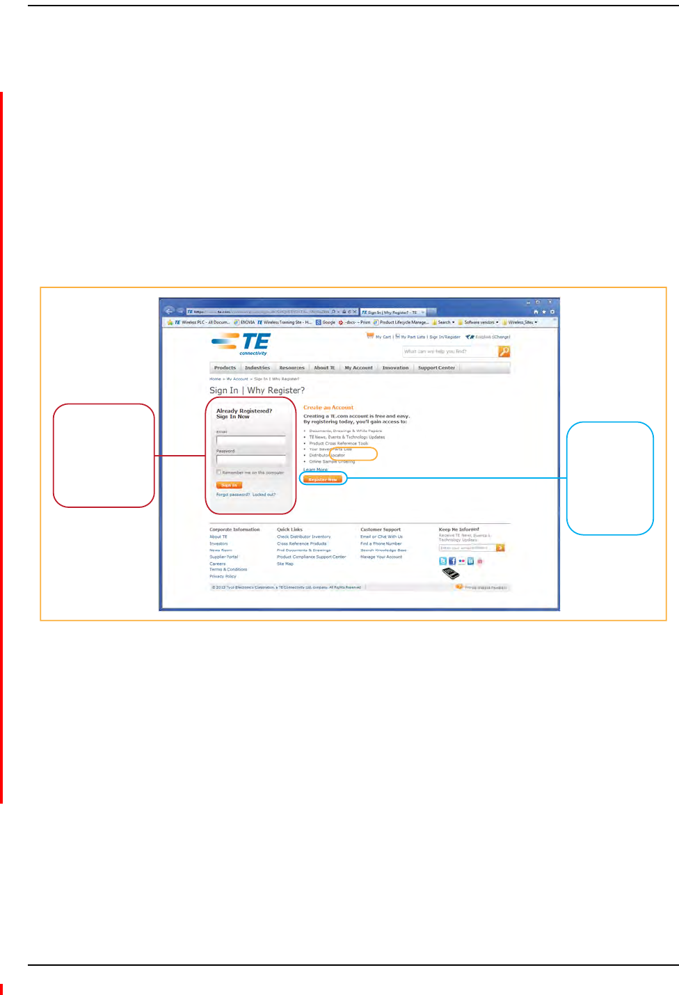
2AccesstotheCustomerPortalrequiresauseraccountandpassword.OntheSign Inpage,do
oneofthefollowing:
3OntheWirelessCustomerPortalhomepageintheKnowledge Centerpanel,clicktheManualsand
DataSheetslink.
4OntheManualsandDataSheetspage,dothefollowing:
aIntheDocument Repositorypanel,scrolltothesectionfortheproductlineofthedocument
thatyouwanttoaccess.
bClickonthetitleofthemanualthatyouwishtoopen.
c(Optional)SavethePDFtoyourPCorlaptop.
If you have an
account, enter
your Email and
Password and
click Sign In.
If you don’t
have an
account, click
Register Now
and follow the
prompts.

Preface
Page 4 InterReach Fusion Wideband Installation, Operation, and Reference Manual
© 2013 TE Connectivity Ltd D-620616-0-20 Rev H • TECP-77-044 Issue 7 • May 2013
CONVENTIONSINTHISMANUAL
Thefollowingtableliststhetypestyleconventionsusedinthismanual.
Measurements
Thismanuallistsmeasurementsfirstinmetricunits,andtheninU.S.CustomarySystemofunits
inparentheses.Forexample:0°to45°C(32°to113°F).
DocumentCautionsandNotes
Twotypesofmessages,identifiedbelow,appearinthetext:
CAUTION! Cautiontextindicatesoperationsorstepsthatcouldcausepersonalinjury,induceasafety
probleminamanageddevice,destroyorcorruptinformation,orinterruptorstopservices.
NOTE: Notetextcontainsinformationaboutspecialcircumstances.
DocumentFonts
Youwillfindthefollowingfontconventionsinusethroughoutthedocument.
•ThisfontrepresentsareferencetoanEMSdialogbox,menuitem,configurationoption,or
otherparameter.
•<This Font>inanglebracketsrepresentsareferencetoanEMSdialogbox,menuitem,
configurationoption,orotherparameterthatisavariable.Thetextwithintheanglebrackets
changesaccordingtoagetorsetcommand.Forexample:
–ThePasswordfor<username>hasbeenchangedmessagedisplays.
–ThePasswordforJohnSmithhasbeenchangedmessagedisplays.
•This fontrepresentsnon‐variabletextthatyoutypeataprompt.
•THIS FONTrepresentskeysthatyouneedtopressonyourkeyboard.

Standards Conformance
InterReach Fusion Wideband Installation, Operation, and Reference Manual Page 5
D-620616-0-20 Rev H • TECP-77-044 Issue 7 • May 2013 © 2013 TE Connectivity Ltd.
STANDARDSCONFORMANCE
•FusionWidebandusestheTIA‐570‐Bcablingstandardsforeaseofinstallation.
•Referto“AppendixB:Compliance”onpage203forcomplianceinformation.
CAUTION! Theuseriscautionedthatchangesormodificationsnotexpresslyapprovedbytheparty
responsibleforcompliancecouldvoidtheuser’sauthoritytooperatetheequipment.

Preface
Page 6 InterReach Fusion Wideband Installation, Operation, and Reference Manual
© 2013 TE Connectivity Ltd D-620616-0-20 Rev H • TECP-77-044 Issue 7 • May 2013
RELATEDPUBLICATIONS
•AdminBrowserUserManual,TEpartnumberD‐620607‐0‐20
•FlexWaveFocusConfiguration,Installation,andReferenceManual;TEpartnumber8500‐10
•InterReachUnisonInstallation,Operation,andReferenceManual;TEpartnumber8700‐50
YoucandownloadFusionuserdocumentationfromtheTECustomerPortal(see“TECustomer
Portal”onpage3).

InterReach Fusion Wideband Installation, Operation, and Reference Manual Page 7
D-620616-0-20 Rev H • TECP-77-044 Issue 7 • May 2013 ©2013 TE Connectivity Ltd.
INTERREACHFUSIONWIDEBANDSYSTEMDESCRIPTION
SystemOverview..................................................................................................................................................8
SystemHardwareDescription.............................................................................................................................10
SystemOA&MCapabilitiesOverview .................................................................................................................12
SystemMonitoringandReporting .......................................................................................................................13
UsingAlarmContacts ........................................................................................................................................... 14
SystemConnectivity ...........................................................................................................................................15
SystemOperation...............................................................................................................................................16
SystemSpecifications .........................................................................................................................................17
RFEnd‐to‐EndPerformance ................................................................................................................................20
2100/1800RAU(FSN‐W1‐2118‐1) ....................................................................................................................... 20
2100HP/1800HP(FSN‐W1‐2118‐1‐HP)............................................................................................................... 21
2100HighPowerRAU(FSN‐W1‐21HP‐1) ............................................................................................................. 22
1900/AWSRAU(FSN‐W1‐1921‐1)........................................................................................................................ 22
800/850/1900RAU(FSN‐W2‐808519‐1).............................................................................................................. 23
700/AWSRAU(FSN‐W2‐7021‐1).......................................................................................................................... 24
700/700(UpperC)MIMORAU(FSN‐W2‐7575‐1)................................................................................................ 25
700/700(LowerABC)MIMORAU ........................................................................................................................ 25
700ABC/AWSHP/AWSHPRAU(FSN‐W4‐702121‐1‐HP) .................................................................................... 25
700UC/AWSHP/AWSHPRAU(FSN‐W4‐752121‐1‐HP) ...................................................................................... 26
850/1900HP/AWSHPRAU(FSN‐W5‐851921‐1‐HP)............................................................................................ 27
2500/2500RAU(FSN‐2500‐2‐WMAX).................................................................................................................. 28
2600/2600RAU(FSN‐W3‐2626‐1) ....................................................................................................................... 28
Topics Page

InterReach Fusion Wideband System Description
Page 8 InterReach Fusion Wideband Installation, Operation, and Reference Manual
© 2013 TE Connectivity Ltd D-620616-0-20 Rev H • TECP-77-044 Issue 7 • May 2013
SYSTEMOVERVIEW
InterReachFusionWidebandisanintelligentfiberoptics/CATV,multi‐band(frequencies)
wirelessnetworkingsystemdesignedtohandlebothwirelessvoiceanddatacommunications
overlicensedfrequencies.Itprovideshigh‐quality,ubiquitous,seamlessaccesstothewireless
networkinlargerbuildings.
FusionWidebandprovidesRFcharacteristicsdesignedforlargepublicandprivatefacilitiessuch
ascampusenvironments,airports,shoppingmalls,subways,conventioncenters,sportsvenues,
andsoon.FusionWidebandusesmicroprocessorstoenablekeycapabilitiessuchas
software‐selectablebandsettings,automaticgaincontrol,abilitytoincrementallyadjust
downlink/uplinkgain,end‐to‐endalarmingofallcomponentsandtheassociatedcable
infrastructure,andahostofadditionalcapabilities.
TheFusionWidebandsystemsupportsmajorwirelessstandardsandairinterfaceprotocolsin
usearoundtheworld,including:
•Frequencies:700MHz,800MHz,850MHz,1700MHz,1800MHz,1900MHz,2100MHz,2500
MHz,2600MHz.
•VoiceProtocols:AMPS,TDMA,CDMA,GSM/EGSM,WCDMA,LTE,WiMAX
•DataProtocols:CDPD,EDGE,GPRS,WCDMA,CDMA2000,1xRTT,EV‐DO,LTE,Paging,and
WiMAX
TheFusionWidebandsystemsupportsthreeconfigurablebands:
•Band1in60MHzandcanbeconfiguredfor700MHz,800MHz,1900MHz,2100MHz,2500
MHz,or2600MHz
•Band2in75MHzandcanbeconfiguredfor1700MHz,1800MHz,1900MHz,2100MHz,
2500MHz,or2600MHz
Bothbandssupportallprotocols.
FusionWidebandremoteaccessunits(RAUs)containcombinationsofBand1,Band2,and
Band3frequenciestosupportvariousworldareas.Thesefrequenciesare1800MHz/2100
MHzforEurope,theMiddleEast,andAsia,or
800MHz/850MHz/1900MHzforNorthAmerica.RefertoTable4onpage19foraspecific
listofsupportedRAUs.
•Band3(onlyusedforNorthAmerica:FSN‐W2‐808519‐1,FSN‐W2‐7021‐1,FSN‐W2‐7070‐1,
FSN‐W2‐7575‐1,FSN‐W4‐702121‐1‐HP,FSN‐W4‐752121‐1‐HP,and
FSN‐W5‐851921‐1‐HP).Forexample,theFSN‐W2‐808519‐1RAUBand3isa25MHz
sub‐bandofthe60MHzBandandBand1isan18MHzsub‐bandofthe60MHzBand.
TheFusionWidebandsystemhasthefollowingkeysystemfeatures
•Multi‐Band,supportstwoormorefullbandfrequenciesforspectrumgrowth.
•SuperiorRFperformance,particularlyintheareasofIP3andnoisefigure.
•Highdownlinkcompositepowerandlowuplinknoisefigureenablessupportofalarge
numberofchannelsandlargercoveragefootprintperantenna.
•SoftwareconfigurableMainandExpansionHubsallowthefrequencybandstobe
configuredinthefield.

System Overview
InterReach Fusion Wideband Installation, Operation, and Reference Manual Page 9
D-620616-0-20 Rev H • TECP-77-044 Issue 7 • May 2013 © 2013 TE Connectivity Ltd.
•Eithersingle‐modeormulti‐modefibercanbeused,supportingflexiblecabling
alternatives(inadditiontostandardCATV75Ohmcabling).Youcanselectthecablingtype
tomettheresidentcablinginfrastructureofthefacilityanduniquebuildingtopologies.
•Extendedsystem“reach.”Usingsingle‐modefiber,fiberrunscanbealongas6kilometers
(creatingatotalsystem“wingspan”of12kilometers).Alternatively,withmulti‐modefiber,
fiberrunscanbeaslongas500meters.
•Standard75OhmCATVcable,canberunupto130metersforRG‐59cable;140metersfor
RG‐6;235metersforRG‐11usingCommScope2065V,2279V,and2293Kcables.
•FlexibleRFconfigurationcapabilities,including:
–Systemgain:Abilitytomanuallysetgainin1dBsteps,from0to15dB,onbothdownlink
anduplink.
–RAU:
RAUuplinkanddownlinkgaincanbeindependentlyattenuated0or10dB.
Uplinklevelcontrolprotectsthesystemfrominputoverloadandcanbeoptimizedfor
eitherasingleoperatorormultipleoperators/protocols.
VSWRcheckonRAUreportsifthereisadisconnectedantenna.
•Firmwareupdatesaredownloaded(eitherlocallyorremotely)tothesystemwhenany
modificationsaremadetotheproduct,includingtheadditionofnewsoftwarecapabilities
andservices.
•OA&Mcapabilities,includingfaultisolationtothefieldreplaceableunit,reportingofallfault
andwarningconditions,anduser‐friendlywebbrowseruserinterfaceOA&Msoftware
package.

InterReach Fusion Wideband System Description
Page 10 InterReach Fusion Wideband Installation, Operation, and Reference Manual
© 2013 TE Connectivity Ltd D-620616-0-20 Rev H • TECP-77-044 Issue 7 • May 2013
SYSTEMHARDWAREDESCRIPTION
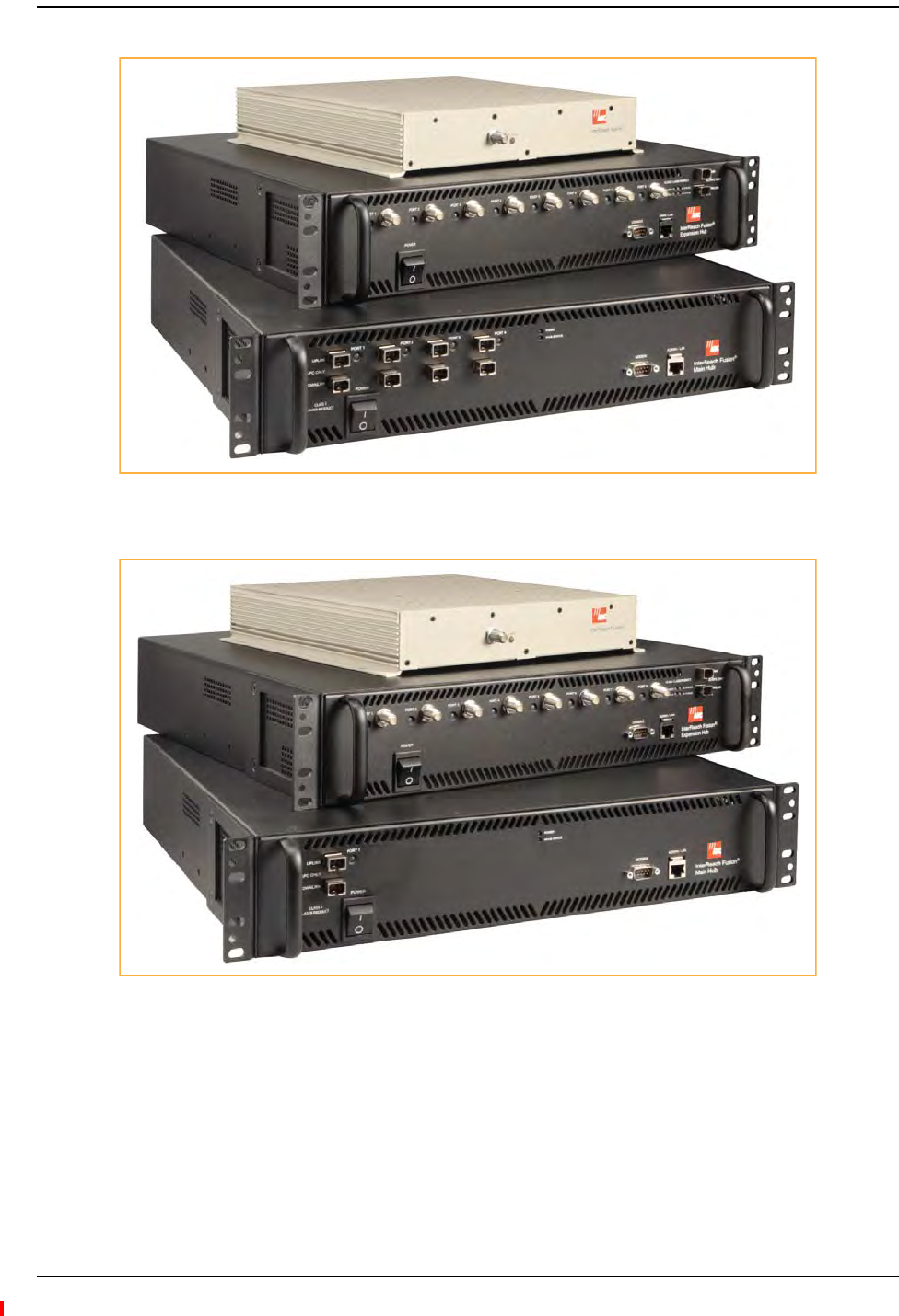
TheInterReachFusionWidebandsystemconsistsofthreemodularcomponents:
•19"rack‐mountableMainHub(connectstoupto4ExpansionHubs,exceptfortheOnePort
MainHubconfigurationthatsupports1ExpansionHub)
–ConvertsRFsignalstoopticalIFonthedownlink;opticalIF‐to‐RFontheuplink
–Microprocessorcontrolled(foralarms,monitoring,andcontrol)
–Auto‐configurablebands
–SimplexinterfacetoRFsource
–PeriodicallypollsalldownstreamRAUsforsystemstatus,andautomaticallyreportsany
faultorwarningconditions
•19”rackmountableExpansionHub(connectstoupto8RemoteAccessUnits)
–Opticalsignalconversiontoelectricalonthedownlink;electricaltoopticalontheuplink
–Microprocessorcontrolled(foralarms,monitoring,andcontrol)
–Softwareconfigurableband(basedoncommandsfromtheMainHub)
–SuppliesDCpowertoRAUsoverCATVcable.
•RemoteAccessUnit(RAU)
–ConvertsIFsignalstoRFonthedownlink;RF‐to‐IFontheuplink
–Microprocessorcontrolled(foralarms,monitoring,andcontrol)
–Multi‐bandprotocolindependent,frequencyspecificunits
TheminimumconfigurationofaFusionWidebandsystemisoneMainHub,oneExpansionHub,
andoneRAU(1‐1‐1).ThemaximumconfigurationofasystemisoneMainHub,fourExpansion
Hubs,and32RAUs(1‐4‐32).Multiplesystemscanbecombinedtoprovidelargerconfigurations.
NOTE: TheFusionWidebandOnePortMainHub(PN:FSN‐W1‐MH‐2‐1P,FSN‐W2‐MH‐3‐1P,
FSN‐W3‐MH‐1P,FSN‐W4‐MH‐1P,andFSN‐W5‐MH‐1P)configurationisacostreducedversionof
theFusionWidebandMainHubandsupportsonlyoneExpansionHub(upto8RAUs).
TheFusionWidebandOnePortMainHubis“softwarelocked”to1port2fiberports.
Additionalportsaredisabledinternally.Pleasedonotattempttoremovethefront
panelfiberportplate,sincedoingsowillvoidtheproductwarranty.
System Hardware Description
InterReach Fusion Wideband Installation, Operation, and Reference Manual Page 11
D-620616-0-20 Rev H • TECP-77-044 Issue 7 • May 2013 © 2013 TE Connectivity Ltd.
Figure1.Fusion Wideband System Hardware
Figure2.Fusion Wideband One Port System Hardware
InterReach Fusion Wideband System Description
Page 12 InterReach Fusion Wideband Installation, Operation, and Reference Manual
© 2013 TE Connectivity Ltd D-620616-0-20 Rev H • TECP-77-044 Issue 7 • May 2013
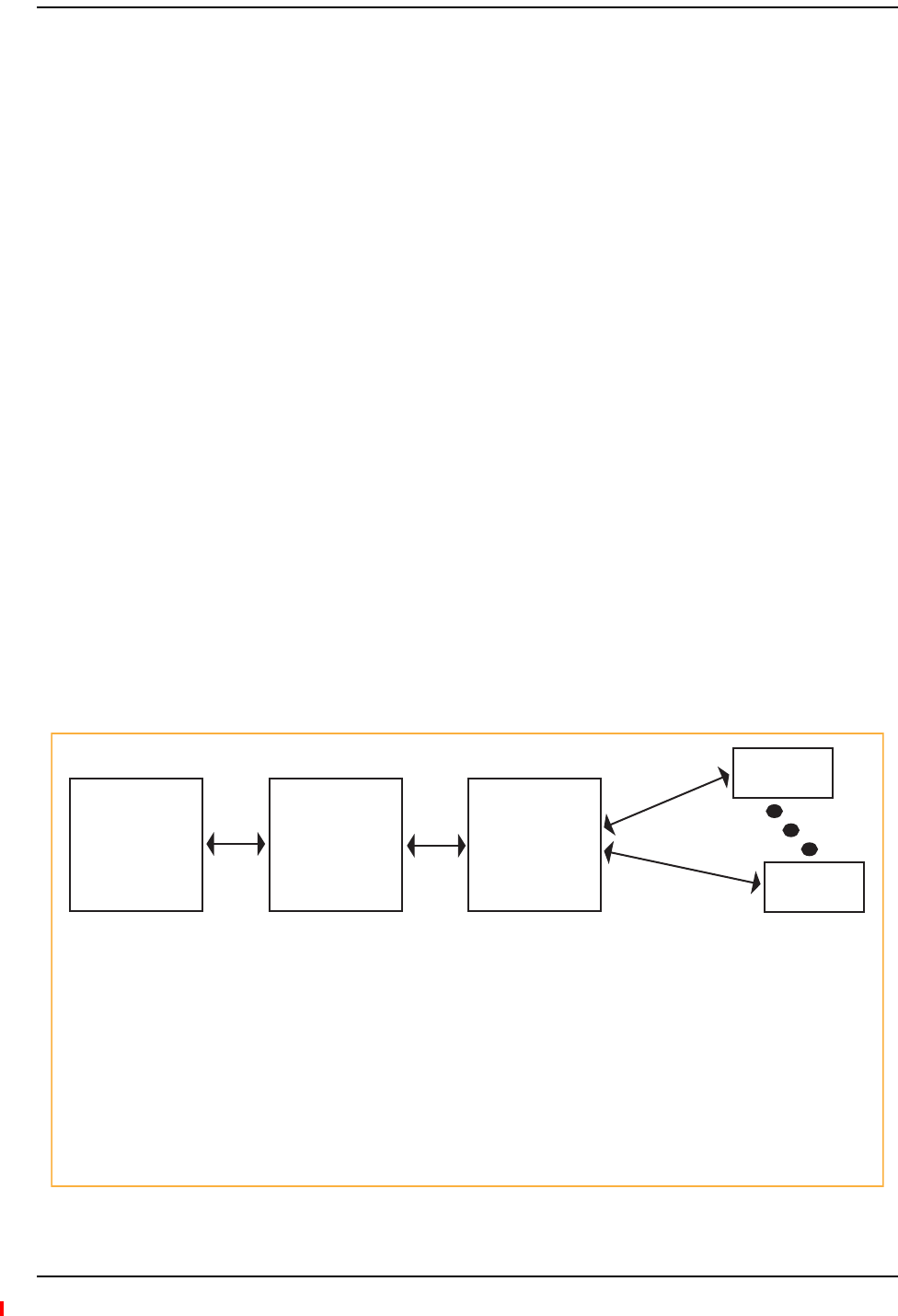
SYSTEMOA&MCAPABILITIESOVERVIEW
InterReachFusionWidebandismicroprocessorcontrolledandcontainsfirmwaretoenablemuch
oftheoperations,administration,andmaintenance(OA&M)functionality.
Completealarming,downtothefieldreplaceableunit(thatis,FusionWidebandMainHub,
ExpansionHub,andRemoteAccessUnit)andthecablinginfrastructure,isavailable.Allevents
occurringinasystem,definedasaFusionWidebandMainHubandallofitsassociatedExpansion
HubsandRemoteAccessUnits,areautomaticallyreportedtotheMainHub.TheMainHub
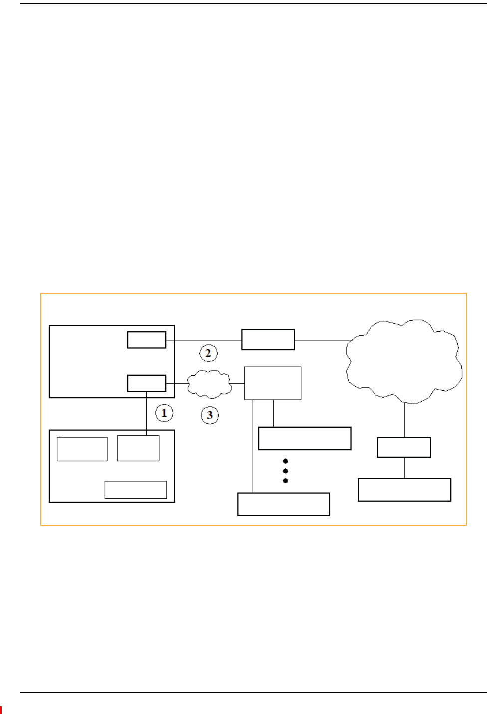
monitorssystemstatusandcommunicatesthatstatususingthefollowingmethods:
•Normallyclosed(NC)alarmcontactclosurescanbetiedtostandardNCalarmmonitoring
systemsordirectlytoabasestationforbasicalarmmonitoring.
•ConnectionMethods:
–TheMainHub’sfrontpanelRJ‐45portconnectsdirectlytoaPC(forlocalEthernetaccess).
–TheMainHub’sfrontpanelRS‐232serialportconnectsdirectlytoamodem(forremote
access).
–Remoteaccessisalsoavailablewithanoptional100BASE‐TLANswitchconnectionsto
theRJ‐45port.
Figure3.Three Methods for OA&M Communications
RS-232 Modem
LAN
Switch
Ethernet TCP/IP
RS-232
Modem
RJ-45
Ethernet
AdminBrowser
Ethernet
Fusion Wideband
Main Hub Modem
Fusion Wideband Main Hub
PSTN
Use AdminBrowser to configure or monitor a local or remote Fusion Wideband system.
PC/Laptop running a
Standard Browser
Fusion Wideband
Main Hub
Fusion Wideband
Main Hub
System OA&M Capabilities Overview
InterReach Fusion Wideband Installation, Operation, and Reference Manual Page 13
D-620616-0-20 Rev H • TECP-77-044 Issue 7 • May 2013 © 2013 TE Connectivity Ltd.
AdminBrowserOA&MsoftwarerunsontheFusionWidebandMainHubmicroprocessorand
communicatestoitsdownstreamExpansionHubsandassociatedRAUs.UsingAdminBrowser,
youcanperformthefollowingfromanystandardwebbrowser(InternetExplorer)runningon
yourPC/laptopsystem:
•Configureanewlyinstalledsystem
•Changesystemparameters
•Performanend‐to‐endsystemtest
•Querysystemstatus
RefertotheAdminBrowserUserManual(D‐620607‐0‐20)forinformationaboutinstallingand
usingAdminBrowsersoftware.
SystemMonitoringandReporting
EachFusionWidebandMainHubinthesystemconstantlymonitorsitself,itsExpansionHubs,
andtheirdownstreamRAUsforinternalfaultandwarningconditions.Theresultsofthis
monitoringarestoredinmemoryandcomparedagainstnewresults.
WhenaMainorExpansionHubdetectsachangeinstatus,itreportsafaultorwarningalarm.
FaultsarealsoindicatedlocallybyredstatusLEDs.Bothfaultsandwarningsarereportedto
AdminBrowsersoftwareanddisplayedonaPC/laptopconnectedtotheMainHub’sRJ‐45port.
PassiveantennasconnectedtotheRAUsarenotmonitoredautomatically.PerformaSystemTest
toretrievestatusinformationaboutantennas.
UsingAdminBrowser,youcaninstallanewsystemornewcomponents,changesystem
parameters,andquerysystemstatus.Figure2‐4illustrateshowthesystemreportsitsstatusto
AdminBrowser.
Figure4.System Monitoring and Reporting
PC/Laptop
running a
standard
web browser
Fusion Wideband
Main Hub
AdminBrowser
Fusion Wideband
Expansion Hub
AdminBrowser
RAU
RAU
Use a standard
browser to communicate
with remotely or locally
installed Fusion Wideband
systems running
AdminBrowser.
If a fault or warning
condition is reported,
the AdminBrowser
graphical user interface
indicates the problem
on your standard PC
browser.
The Main Hub queries status
of each Expansion Hub and
each RAU and compares it
to previously stored
status.
If a fault is detected,
LEDs on the front panel turn
red.
The Expansion Hub queries
the status of each RAU and
compares it to the previously
stored status.
If a fault is detected, LEDs
on the front panel turn red.
Each RAU passes its status to
the Hub.
If a fault is detected, the
Alarm LED is red. If no
fault is detected, the LED
is green.

InterReach Fusion Wideband System Description
Page 14 InterReach Fusion Wideband Installation, Operation, and Reference Manual
© 2013 TE Connectivity Ltd D-620616-0-20 Rev H • TECP-77-044 Issue 7 • May 2013
UsingAlarmContacts
YoucanconnecttheDB‐9femaleconnectorontherearpaneloftheFusionWidebandMainHub
toalocalbasestationortoadaisy‐chainedseriesofFusionand/orFlexWaveFocussystems.
WhenyouconnectFlexWaveFocusoraBTStotheFusionWideband,theFusionWidebandMain
Huboutputsthealarms(alarmsource)andFlexWaveFocusortheBTSreceivesthealarms
(alarmsense).ThisisdescribedinSection7.7.1onpage7‐59.
System Connectivity
InterReach Fusion Wideband Installation, Operation, and Reference Manual Page 15
D-620616-0-20 Rev H • TECP-77-044 Issue 7 • May 2013 © 2013 TE Connectivity Ltd.
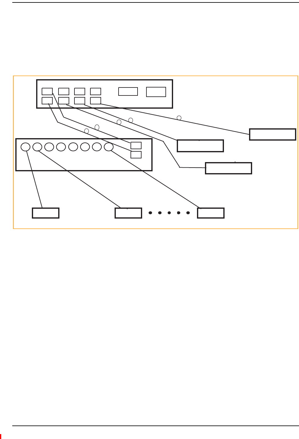
SYSTEMCONNECTIVITY
ThedoublestararchitectureoftheFusionWidebandsystem,illustratedinFigure2‐5,provides
excellentsystemscalabilityandreliability.Thesystemrequiresonlyonepairoffibersforeight
antennapoints.Thismakesanysystemexpansion,suchasaddinganextraantennaforadditional
coverage,potentiallyaseasyaspullinganextraCATVcable.
Figure5.Fusion Wideband’s Double Star Architecture
PORT 1 PORT 2 PORT 3 PORT 4
RS-232 RJ-45
RAU RAU RAU
Expansion Hub
Main Hub
Expansion Hub
Expansion Hub
Expansion Hub
Fiber
CATV (RG-59, 6, or 11) CATV CATV
Up to 8 RAUs per Expansion Hub
InterReach Fusion Wideband System Description
Page 16 InterReach Fusion Wideband Installation, Operation, and Reference Manual
© 2013 TE Connectivity Ltd D-620616-0-20 Rev H • TECP-77-044 Issue 7 • May 2013
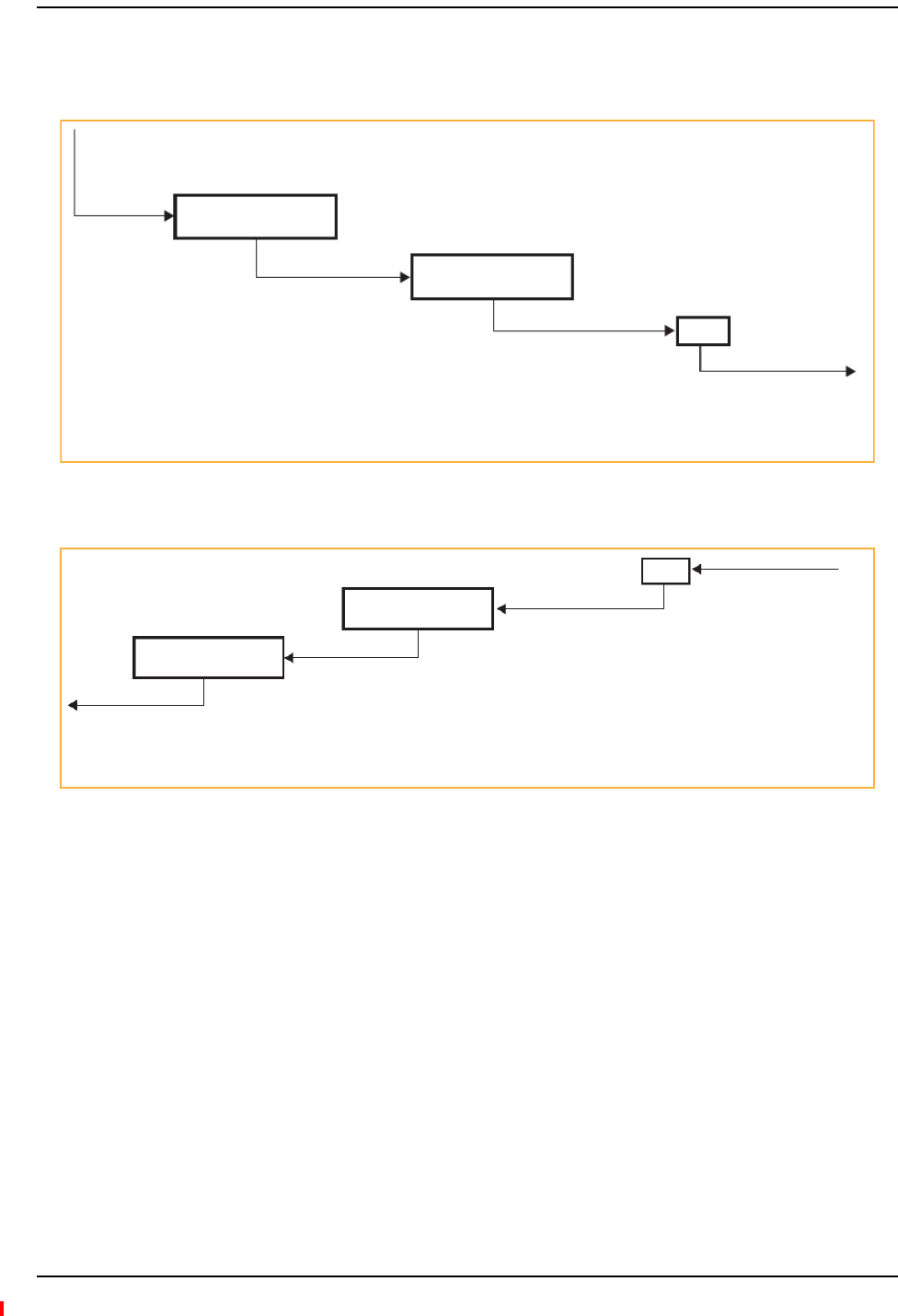
SYSTEMOPERATION
Figure6.Downlink (Base Station to Wireless Devices)
Figure7.Uplink (Wireless Devices to Base Station)
Main Hub
Expansion Hub
RAU
The Main Hub receives downlink
RF signals from a base station using
50 Ohm coaxial cable.
The Main Hub converts the RF signals to IF, then
to optical signals and sends them to Expansion
Hubs (up to four) using optical fiber cable.
The Expansion Hub converts the optical signals
to electrical signals and sends them to RAUs
(up to eight) using 75 Ohm CATV cable.
The RAU converts the IF signals
to RF and sends them to passive
antennas using 50 Ohm coaxial
cable.
Main Hub
Expansion Hub
RAU
The Main Hub sends
uplink RF signals to a
base station using
50 Ohm coaxial cable.
The Main Hub receives
the optical signals from
the Expansion Hubs (up
to four) using optical fiber
cable and con-verts them
to RF sig-nals.
The Expansion Hub receives
the IF signals from the RAUs
(up to eight) using CATV cable
and converts them to optical
signals.
The RAU receives uplink
RF signals from the
passive antenna using
50 Ohm coaxial cable and
converts them to IF signals.

System Specifications
InterReach Fusion Wideband Installation, Operation, and Reference Manual Page 17
D-620616-0-20 Rev H • TECP-77-044 Issue 7 • May 2013 © 2013 TE Connectivity Ltd.
SYSTEMSPECIFICATIONS
NOTE: Note:TheFusionWidebandMainHub’stypicalpowerconsumptionassumesthattheCATV
RG‐59cablelengthisnomorethan130meters,theRG‐6cablelengthisnomorethan140
meters,andRG‐11cablelengthisnomorethan235metersusingCommScope2065V,2279V,and
2293Kcables.
Table1.PhysicalSpecifications
Parameter Main Hub Expansion Hub Remote Access Unit
IF/RF Connectors 4-type “N” female(a)
(50 Ohm),
1 Downlink/Uplink pair per
band
8-type “F”, female
(CATV 75 Ohm)
One F, female (CATV -75 Ohm)
One N, female(b)
(antenna-50 Ohm)
External Alarm Connector
(contact source)
One, 9-pin D-sub, female One, 9-pin D-sub, female —
ADMIN/LAN Interface
Connectors
One RJ-45, female
One 9-pin D-sub, male for
optional modem
One RJ-45, female
One 9-pin D-sub, male
—
Fiber Connectors(c) 4 pair, SC/APC (d) One pair, SC/APC —
LED Alarm and Status
Indicators
Unit Status (One pair):
•Power
• Main Hub Status
Downstream Unit Status
(One per fiber port):
• Expansion Hub/RAU
Unit Status (One pair):
•Power
• Expansion Hub Status
Fiber Link Status (One pair):
•DL Status
•U
L Status
Port Status:
• One per F connector port
•L
ink/RAU
Unit Status (One pair):
•Link
•A
larm
Power (AC Option) Rating: 100–240V AC, 1A,
50–60 Hz
Operating Range: 90–132V
AC/170-250V
AC auto-ranging
Rating: 100–240V AC, 6A,
50–60 Hz
Operating Range: 90–132V
AC/170-250V AC
auto-ranging
—
Power (DC Option) Rating: 38–64V DC, 2.5A Rating: 38-64V DC, 14A
Power Consumption (W) 30 4 RAUs: 290 typical, 360 max.
8 RAUs: 500 typical, 630 Max.
—
Enclosure Dimensions (e)
(height ´ width ´ depth)
89 mm × 438 mm × 381 mm
(3.5 in. × 17.25 in. × 15 in.)
2U
89 mm × 438 mm × 381 mm
(3.5 in. × 17.25 in. × 15 in.)
2U
54 mm x 286 mm x 281 mm
(2.13 in. × 11.25 in. × 11.13 in.)
Weight < 5.5 kg (< 12 lbs.) < 6.6 kg (< 14.5 lbs.) < 2.1 kg (< 4.6 lbs.)
a 6-type N, female connectors for FSN-W2-MH-1, FSN-W2-MH-3, FSN-W4-MH-1, and FSN-W5-MH-1 Main Hub.
b 2-type N, female connectors for FSN-W1-1921-1, FSN-W2-808519-1, FSN-W2-7575-1, FSN-W2-7070-1, FSN-W3-2626-1,
FSN-W4-702121-1-HP, FSN-W4-752121-1-HP, FSN-W5-851921-1-HP, and FSN-2500-2-WMAX RAUs.
c It is critical to system performance that only SC/APC fiber connectors are used throughout the fiber network, including fiber
distribution panels.
d FSN-W1-MH-2-1P, FSN-W2-MH-3-1P, FSN-W3-MH-1P, FSN-W4-MH-1P, and FSN-W5-MH-1P support only one pair, SP/APC
fibers.
e Excluding angle-brackets for 19'' rack hub mounting of the hub.

InterReach Fusion Wideband System Description
Page 18 InterReach Fusion Wideband Installation, Operation, and Reference Manual
© 2013 TE Connectivity Ltd D-620616-0-20 Rev H • TECP-77-044 Issue 7 • May 2013
Table2.WavelengthandLaserPowerSpecifications
Measured Output Power
Wavelength Main Hub Expansion Hub
1310 nm +20 nm 890 uW 3.8 mW
Table3.EnvironmentalSpecifications
Parameter Main Hub and Expansion Hub RAU
Operating Temperature 0° to +45°C (+32° to +113°F) –25° to +45°C (–13° to +113°F)
Non-operating Temperature –20° to +85°C (–4° to +185°F) –25° to +85°C (–13° to +185°F)
Operating Humidity; non-condensing 5% to 95% 5% to 95%

System Specifications
InterReach Fusion Wideband Installation, Operation, and Reference Manual Page 19
D-620616-0-20 Rev H • TECP-77-044 Issue 7 • May 2013 © 2013 TE Connectivity Ltd.
Table4.FrequencyBandsCoveredbyFusionWidebandRAUs
Fusion RAU Part Number Fusion
Band
RF Passband
Downlink (MHz) Uplink (MHz) MAIN HUB/
RAU Band
RAU
Bandwidth
2100/1800 FSN-W1-2118-1 2100 2110-2170 1920-1980 1 60 MHz
2100 HP/1800 HP FSN-W1-2118-1-HP 1800 1805-1880 1710-1785 2 75 MHz
2100 High Power
(single-band RAU)
FSN-W1-21HP-1 2100 2110-2170 1920-1980 1 60 MHz
1900/AWS FSN-W1-1921-1 1900 (A-F) 1930-1990 1850-1910 1 60 MHz
AWS 2110-2155 1710-1755 2 45 MHz
800/850/1900 FSN-W2-808519-1 800 851-869 806-824 1
(sub-band 1A)
18 MHz
850 869-894 824-849 3
(sub-band 1B)
25 MHz
1900 (A - F) 1930-1990 1850-1910 2 60 MHz
700/AWS FSN-W2-7021-1 700 (Upper C) 746-757 776-787 1
(sub-band 1A)
11 MHz
700
(Lower ABC)
728-746 698-716 3
(sub-band 1B)
18 MHz
AWS 2110-2155 1710-1755 2 45 MHz
700/700 MIMO
(Upper C)
FSN-W2-7575-1 700 (Upper C) 746-757 776-787 1
(sub-band 1A)
11 MHz
700 (Upper C) 746-757 776-787 3
(sub-band 1B)
11 MHz
700/700 MIMO
(Lower ABC)
FSN-W2-7070-1 700
(Lower ABC)
728-746 698-716 1
(sub-band 1A)
18 MHz
700
(Lower ABC)
728-746 698-716 3
(sub-band 1B)
18 MHz
700 ABC/AWS HP/
AWS HP
FSN-W4-702121-1-HP AWS 2110-2155 1710-1755 1
(sub-band 1A)
45 MHz
700
(Lower ABC)
728-746 698-716 3
(sub-band 1B)
18 MHz
AWS 2110-2155 1710-1755 2 45 MHz
700 UC/AWS HP/
AWS HP
FSN-W4-752121-1-HP AWS 2110-2155 1710-1755 1
(sub-band 1A)
45 MHz
700 (Upper C) 746-757 776-787 3
(sub-band 1B)
11 MHz
AWS 2110-2155 1710-1755 2 45 MHz
850/1900 HP/
AWS HP
FSN-W5-851921-1-
HP
AWS 2110-2155 1710-1755 1
(sub-band 1A)
45 MHz
850 869-894 824-849 3
(sub-band 1B)
25 MHz
1900 (A - G) 1930-1995 1850-1915 2 65 MHz
2500/2500 FSN-2500-2-WMAX 2500 2496-2690 2496-2690 1 30 MHz
2500 2496-2690 2496-2690 2 30 MHz
2600/2600 FSN-W3-2626-1 2600 2620-2690 2500-2570 1 70 MHz
2600 2620-2690 2500-2570 2 70 MHz

InterReach Fusion Wideband System Description
Page 20 InterReach Fusion Wideband Installation, Operation, and Reference Manual
© 2013 TE Connectivity Ltd D-620616-0-20 Rev H • TECP-77-044 Issue 7 • May 2013
RFEND‐TO‐ENDPERFORMANCE
ThefollowingtableslisttheRFend‐to‐endperformanceofeachprotocol.
NOTE: Thesystemgainisadjustablein1dBstepsfrom0to15dB,andthegainofeachRAUcanbe
attenuated0or10dB.
2100/1800RAU(FSN‐W1‐2118‐1)
Table5.2100MHzRFEnd‐to‐EndPerformance
Parameter
Typical
Downlink Uplink
Average gain with 130 m RG-59 at 25°C (77°F) (dB) 15 15
Ripple with 130 m RG-59 (dB) 4.5 4.5
Output IP3 (dBm) 38
Input IP3 (dBm) -5
Output 1 dB Compression Point (dBm) 26
Noise Figure 1 MH, 1 EH, 8 RAUs (dB) 17
Noise Figure 1 MH, 4 EH, 32 RAUs (dB) 23
Table6.1800MHzRFEnd‐to‐EndPerformance
Parameter
Typical
Downlink Uplink
Average gain with 130 m RG-59 at 25°C (77°F) (dB) 15 15
Ripple with 130 m RG-59 (dB) 4.5 4.5
Output IP3 (dBm) 38
Input IP3 (dBm) –5
Output 1 dB Compression Point (dBm) 26
Noise Figure 1 MH, 1 EH, 8 RAUs (dB) 17
Noise Figure 1 MH, 4 EH, 32 RAUs (dB) 23

RF End-to-End Performance
InterReach Fusion Wideband Installation, Operation, and Reference Manual Page 21
D-620616-0-20 Rev H • TECP-77-044 Issue 7 • May 2013 © 2013 TE Connectivity Ltd.
2100HP/1800HP(FSN‐W1‐2118‐1‐HP)
Table7.2100MHzRFEnd‐to‐EndPerformance
Parameter
Typical
Downlink Uplink
Average gain with 130 m RG-59 at 25°C (77°F) (dB) 20 15
Ripple with 130 m RG-59 (dB) 4.5 4.5
Output IP3 (dBm) 42
Input IP3 (dBm) -5
Output 1 dB Compression Point (dBm) 30
Noise Figure 1 MH, 1 EH, 8 RAUs (dB) 17
Noise Figure 1 MH, 4 EH, 32 RAUs (dB) 23
Table8.1800MHzRFEnd‐to‐EndPerformance
Parameter
Typical
Downlink Uplink
Average gain with 130 m RG-59 at 25°C (77°F) (dB) 18 15
Ripple with 130 m RG-59 (dB) 4.5 4.5
Output IP3 (dBm) 42
Input IP3 (dBm) –5
Output 1 dB Compression Point (dBm) 30
Noise Figure 1 MH, 1 EH, 8 RAUs (dB) 17
Noise Figure 1 MH, 4 EH, 32 RAUs (dB) 23

InterReach Fusion Wideband System Description
Page 22 InterReach Fusion Wideband Installation, Operation, and Reference Manual
© 2013 TE Connectivity Ltd D-620616-0-20 Rev H • TECP-77-044 Issue 7 • May 2013
2100HighPowerRAU(FSN‐W1‐21HP‐1)
1900/AWSRAU(FSN‐W1‐1921‐1)
Table9.2100MHzHighPowerRFEnd‐to‐EndPerformance
Parameter
Typical
Downlink Uplink
Average gain with 130 m RG-59 at 25°C (77°F) (dB) a,b 22 15
Ripple with 130 m RG-59 (dB) 4.5 5
Output IP3 (dBm) 44
Input IP3 (dBm) –5
Output 1 dB Compression Point (dBm) 33
Noise Figure 1 MH, 1 EH, 8 RAUs (dB) 17
Noise Figure 1 MH, 4 EH, 32 RAUs (dB) 23
a The system Downlink gain is adjustable in 1 dB steps from 7 to 22 dB (the
High Power RAU adds 7 dB of Downlink gain).
b The system Uplink gain is adjustable in 1 dB steps from 0 to 15 dB.
Table10.1900MHzRFEnd‐to‐EndPerformance
Parameter
Typical
Downlink Uplink
Average gain with 130 m RG-59 at 25°C (77°F) (dB) 15 15
Ripple with 130 m RG-59 (dB) 3.5 4
Output IP3 (dBm) 38
Input IP3 (dBm) –5
Output 1 dB Compression Point (dBm) 26
Noise Figure 1 MH, 1 EH, 8 RAUs (dB) 17
Noise Figure 1 MH, 4 EH, 32 RAUs (dB) 23
Table11.AWSRFEnd‐to‐EndPerformance
Parameter
Typical
Downlink Uplink
Average gain with 130 m RG-59 at 25°C (77°F) (dB) 15 15
Ripple with 130 m RG-59 (dB) 3.5 4
Output IP3 (dBm) 38
Input IP3 (dBm) –5
Output 1 dB Compression Point (dBm) 26
Noise Figure 1 MH, 1 EH, 8 RAUs (dB) 17
Noise Figure 1 MH, 4 EH, 32 RAUs (dB) 23

RF End-to-End Performance
InterReach Fusion Wideband Installation, Operation, and Reference Manual Page 23
D-620616-0-20 Rev H • TECP-77-044 Issue 7 • May 2013 © 2013 TE Connectivity Ltd.
800/850/1900RAU(FSN‐W2‐808519‐1)
Table12.800MHzRFEnd‐to‐EndPerformance
Parameter
Typical
Downlink Uplink
Average gain with 130 m RG-59 at 25°C (77°F) (dB) 15 15
Ripple with 130 m RG-59 (dB) 2.5 3
Output IP3 (dBm) 37
Input IP3 (dBm) –5
Output 1 dB Compression Point (dBm) 25
Noise Figure 1 MH, 1 EH, 8 RAUs (dB) 17
Noise Figure 1 MH, 4 EH, 32 RAUs (dB) 23
Table13.850MHzRFEnd‐to‐EndPerformance
Parameter
Typical
Downlink Uplink
Average gain with 130 m RG-59 at 25°C (77°F) (dB) 15 15
Ripple with 130 m RG-59 (dB) 2.5 3
Output IP3 (dBm) 37
Input IP3 (dBm) –5
Output 1 dB Compression Point (dBm) 25
Noise Figure 1 MH, 1 EH, 8 RAUs (dB) 17
Noise Figure 1 MH, 4 EH, 32 RAUs (dB) 23
Table14.1900MHzRFEnd‐to‐EndPerformance
Parameter
Typical
Downlink Uplink
Average gain with 130 m RG-59 at 25°C (77°F) (dB) 15 15
Ripple with 130 m RG-59 (dB) 3.5 4
Output IP3 (dBm) 38
Input IP3 (dBm) –5
Output 1 dB Compression Point (dBm) 26
Noise Figure 1 MH, 1 EH, 8 RAUs (dB) 17
Noise Figure 1 MH, 4 EH, 32 RAUs (dB) 23

InterReach Fusion Wideband System Description
Page 24 InterReach Fusion Wideband Installation, Operation, and Reference Manual
© 2013 TE Connectivity Ltd D-620616-0-20 Rev H • TECP-77-044 Issue 7 • May 2013
700/AWSRAU(FSN‐W2‐7021‐1)
Table15.700MHz(LowerABC)RFEnd‐to‐EndPerformance
Parameter
Typical
Downlink Uplink
Average gain with 130 m RG-59 at 25°C (77°F) (dB) 15 15
Ripple with 130 m RG-59 (dB) 2.5 3
Output IP3 (dBm) 34
Input IP3 (dBm) –5
Output 1 dB Compression Point (dBm) 22
Noise Figure 1 MH, 1 EH, 8 RAUs (dB) 20
Noise Figure 1 MH, 4 EH, 32 RAUs (dB) 26
Table16.700MHz(UpperC)RFEnd‐to‐EndPerformance
Parameter
Typical
Downlink Uplink
Average gain with 130 m RG-59 at 25°C (77°F) (dB) 15 15
Ripple with 130 m RG-59 (dB) 2.5 3
Output IP3 (dBm) 34
Input IP3 (dBm) –5
Output 1 dB Compression Point (dBm) 22
Noise Figure 1 MH, 1 EH, 8 RAUs (dB) 20
Noise Figure 1 MH, 4 EH, 32 RAUs (dB) 26
Table17.AWSRFEnd‐to‐EndPerformance
Parameter
Typical
Downlink Uplink
Average gain with 130 m RG-59 at 25°C (77°F) (dB) 15 15
Ripple with 130 m RG-59 (dB) 3.5 4
Output IP3 (dBm) 38
Input IP3 (dBm) –5
Output 1 dB Compression Point (dBm) 26
Noise Figure 1 MH, 1 EH, 8 RAUs (dB) 17
Noise Figure 1 MH, 4 EH, 32 RAUs (dB) 23

RF End-to-End Performance
InterReach Fusion Wideband Installation, Operation, and Reference Manual Page 25
D-620616-0-20 Rev H • TECP-77-044 Issue 7 • May 2013 © 2013 TE Connectivity Ltd.
700/700(UpperC)MIMORAU(FSN‐W2‐7575‐1)
700/700(LowerABC)MIMORAU(FSN‐W2‐7070‐1)
700ABC/AWSHP/AWSHPRAU(FSN‐W4‐702121‐1‐HP)
Table18.700MHz(UpperC)RFEnd‐to‐EndPerformance
Parameter
Typical
Downlink Uplink
Average gain with 130 m RG-59 at 25°C (77°F) (dB) 15 15
Ripple with 130 m RG-59 (dB) 2.5 3
Output IP3 (dBm) 38
Input IP3 (dBm) –5
Output 1 dB Compression Point (dBm) 26
Noise Figure 1 MH, 1 EH, 8 RAUs (dB) 17
Noise Figure 1 MH, 4 EH, 32 RAUs (dB) 23
Table19.700MHz(LowerABC)RFEnd‐to‐EndPerformance
Parameter
Typical
Downlink Uplink
Average gain with 130 m RG-59 at 25°C (77°F) (dB) 15 15
Ripple with 130 m RG-59 (dB) 2.5 3
Output IP3 (dBm) 38
Input IP3 (dBm) –5
Output 1 dB Compression Point (dBm) 26
Noise Figure 1 MH, 1 EH, 8 RAUs (dB) 17
Noise Figure 1 MH, 4 EH, 32 RAUs (dB) 23
Table20.700MHz(LowerABC)RFEnd‐to‐EndPerformance
Parameter
Typical
Downlink Uplink
Average gain with 130 m RG-59 at 25°C (77°F) (dB) 15 15
Ripple with 130 m RG-59 (dB) 2.5 3
Output IP3 (dBm) 38
Input IP3 (dBm) –5
Output 1 dB Compression Point (dBm) 26
Noise Figure 1 MH, 1 EH, 8 RAUs (dB) 16
Noise Figure 1 MH, 4 EH, 32 RAUs (dB) 22

InterReach Fusion Wideband System Description
Page 26 InterReach Fusion Wideband Installation, Operation, and Reference Manual
© 2013 TE Connectivity Ltd D-620616-0-20 Rev H • TECP-77-044 Issue 7 • May 2013
700UC/AWSHP/AWSHPRAU(FSN‐W4‐752121‐1‐HP)
Table21.AWSRFEnd‐to‐EndPerformance
Parameter
Typical
Downlink Uplink
Average gain with 130 m RG-59 at 25°C (77°F) (dB) 20 15
Ripple with 130 m RG-59 (dB) 3.5 4
Output IP3 (dBm) 43
Input IP3 (dBm) –5
Output 1 dB Compression Point (dBm) 31
Noise Figure 1 MH, 1 EH, 8 RAUs (dB) 17
Noise Figure 1 MH, 4 EH, 32 RAUs (dB) 23
Table22.700MHz(UpperC)RFEnd‐to‐EndPerformance
Parameter
Typical
Downlink Uplink
Average gain with 130 m RG-59 at 25°C (77°F) (dB) 15 15
Ripple with 130 m RG-59 (dB) 2.5 3
Output IP3 (dBm) 38
Input IP3 (dBm) –5
Output 1 dB Compression Point (dBm) 26
Noise Figure 1 MH, 1 EH, 8 RAUs (dB) 16
Noise Figure 1 MH, 4 EH, 32 RAUs (dB) 22
Table23.AWSRFEnd‐to‐EndPerformance
Parameter
Typical
Downlink Uplink
Average gain with 130 m RG-59 at 25°C (77°F) (dB) 20 15
Ripple with 130 m RG-59 (dB) 3.5 4
Output IP3 (dBm) 43
Input IP3 (dBm) –5
Output 1 dB Compression Point (dBm) 31
Noise Figure 1 MH, 1 EH, 8 RAUs (dB) 17
Noise Figure 1 MH, 4 EH, 32 RAUs (dB) 23

RF End-to-End Performance
InterReach Fusion Wideband Installation, Operation, and Reference Manual Page 27
D-620616-0-20 Rev H • TECP-77-044 Issue 7 • May 2013 © 2013 TE Connectivity Ltd.
850/1900HP/AWSHPRAU(FSN‐W5‐851921‐1‐HP)
Table24.850MHzRFEnd‐to‐EndPerformance
Parameter
Typical
Downlink Uplink
Average gain with 130 m RG-59 at 25°C (77°F) (dB) 15 15
Ripple with 130 m RG-59 (dB) 2.5 3
Output IP3 (dBm) 38
Input IP3 (dBm) –5
Output 1 dB Compression Point (dBm) 26
Noise Figure 1 MH, 1 EH, 8 RAUs (dB) 16
Noise Figure 1 MH, 4 EH, 32 RAUs (dB) 22
Table25.1900MHzRFEnd‐to‐EndPerformance
Parameter
Typical
Downlink Uplink
Average gain with 130 m RG-59 at 25°C (77°F) (dB) 20 15
Ripple with 130 m RG-59 (dB) 3.5 4
Output IP3 (dBm) 43
Input IP3 (dBm) –5
Output 1 dB Compression Point (dBm) 31
Noise Figure 1 MH, 1 EH, 8 RAUs (dB) 17
Noise Figure 1 MH, 4 EH, 32 RAUs (dB) 23
Table26.AWSRFEnd‐to‐EndPerformance
Parameter
Typical
Downlink Uplink
Average gain with 130 m RG-59 at 25°C (77°F) (dB) 20 15
Ripple with 130 m RG-59 (dB) 3.5 4
Output IP3 (dBm) 43
Input IP3 (dBm) –5
Output 1 dB Compression Point (dBm) 31
Noise Figure 1 MH, 1 EH, 8 RAUs (dB) 17
Noise Figure 1 MH, 4 EH, 32 RAUs (dB) 23

InterReach Fusion Wideband System Description
Page 28 InterReach Fusion Wideband Installation, Operation, and Reference Manual
© 2013 TE Connectivity Ltd D-620616-0-20 Rev H • TECP-77-044 Issue 7 • May 2013
2500/2500RAU(FSN‐2500‐2‐WMAX)
2600/2600RAU(FSN‐W3‐2626‐1)
Table27.2500MHzWiMAXRFEnd‐to‐EndPerformance
Parameter
Typical
Downlink Uplink
Average gain with 130 m RG-59 at 25°C (77°F) (dB) 15 15
Ripple with 130 m RG-59 (dB) 4.5 4.5
Output IP3 (dBm) 42.5
Input IP3 (dBm) –5
Output 1 dB Compression Point (dBm) 32
Noise Figure 1 MH, 1 EH, 8 RAUs (dB) 17
Noise Figure 1 MH, 4 EH, 32 RAUs (dB) 23
Table28.2600MHzRFEnd‐to‐EndPerformance
Parameter
Typical
Downlink Uplink
Average gain with 130 m RG-59 at 25°C (77°F) (dB) 15 15
Ripple with 130 m RG-59 (dB) 4.5 5
Output IP3 (dBm) 38
Input IP3 (dBm) –5
Output 1 dB Compression Point (dBm) 26
Noise Figure 1 MH, 1 EH, 8 RAUs (dB) 17
Noise Figure 1 MH, 4 EH, 32 RAUs (dB) 23

InterReach Fusion Wideband Installation, Operation, and Reference Manual Page 29
D-620616-0-20 Rev H • TECP-77-044 Issue 7 • May 2013 ©2013 TE Connectivity Ltd.
FUSIONWIDEBANDMAINHUB
FusionWidebandMainHubOverview................................................................................................................30
FusionWidebandMainHubFrontPanel.............................................................................................................32
OpticalFiberUplink/DownlinkPorts.................................................................................................................... 33
CommunicationsRS‐232SerialConnector........................................................................................................... 33
MainHubLEDIndicators ...................................................................................................................................... 33
UnitStatusLEDs................................................................................................................................................................34
FiberPortLEDs .................................................................................................................................................................34
FusionWidebandMainHubRearPanel............................................................................................................... 35
FusionWidebandMainHubRearPanelConnectors........................................................................................................36
9‐pinD‐subConnector..............................................................................................................................................36
N‐typeFemaleConnectors .......................................................................................................................................36
MainHubSpecifications .....................................................................................................................................37
Faults,Warnings,andStatusMessages...............................................................................................................38
Events ................................................................................................................................................................... 38
ViewPreference ................................................................................................................................................... 38
Topics Page
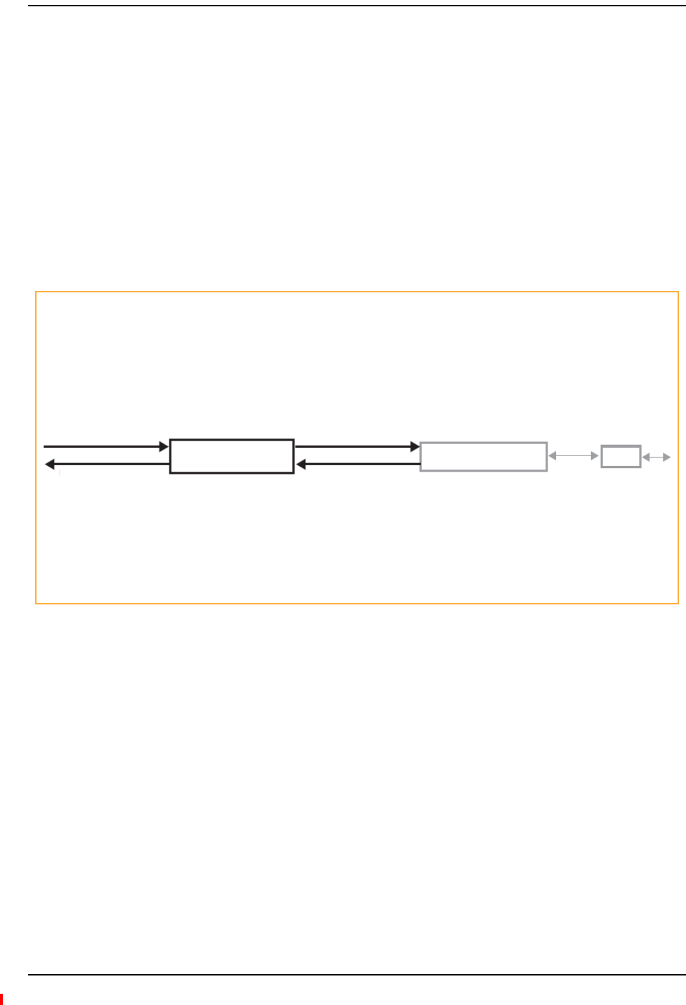
Fusion Wideband Main Hub
Page 30 InterReach Fusion Wideband Installation, Operation, and Reference Manual
© 2013 TE Connectivity Ltd D-620616-0-20 Rev H • TECP-77-044 Issue 7 • May 2013
FUSIONWIDEBANDMAINHUBOVERVIEW
TheFusionWidebandMainHub(showninFigure8)distributesuptothreeindividual(Band1,2,
and3)downlinkRFsignalsfromabasestation,repeater,orFlexWaveFocussystemtouptofour
ExpansionHubs,whichinturndistributethesignalstoupto32RemoteAccessUnits.TheMain
HubalsocombinesuplinksignalsfromtheassociatedExpansionHubs.
FusionWidebandisamulti‐bandsystem.OneRFsource(Band1orRF1)goestothe60MHzband
andtheotherRFsource(Band2orRF2)goestothe75MHzband.Band3(orRF3)goestoa25
MHzsub‐bandofthe60MHzbandandisfunctionalonlywiththe800/850/1900,700/AWS,
700/700(UpperC)MIMO,700/700(LowerABC)MIMO,700ABC/AWSHP/AWSHP,700
UC/AWSHP/AWSHP,and850/1900HP/AWSHPRAU.Thesysteminstallsina19"equipment
rackandisusuallyco‐locatedwiththeRFsourceinatelecommunicationscloset.
Figure8.Main Hub in a Fusion Wideband System
Figure9onpage31showsadetailedviewofthemajorRFandopticalfunctionalblocksofthe
MainHub.
TheFusionWidebandOnePortMainHub(PNs:FSN‐W1‐MH‐2‐1P,FSN‐W2‐MH‐3‐1P,
FSN‐W3‐MH‐1P,FSN‐W4‐MH‐1P,andFSN‐W5‐MH‐1P)configurationisacostreducedversionof
theFusionWidebandMainHubandsupportsonlyoneExpansionHub(upto8RAUs).
Downlink Path: The Main Hub receives up to 3 individual (Band1, 2, or 3) downlink RF signals from a base station, repeater,
or FlexWave Focus system using 50 Ohm coaxial cable. It converts the signals to IF then to optical and sends them to up to
four Expansion Hubs using fiber optic cable.
The Main Hub also sends OA&M communication to the Expansion Hubs using the fiber optic cable. The Expansion Hubs,
in turn, communicate the OA&M information to the RAUs using CATV cable.
Uplink Path: The Main Hub receives uplink optical signals from up to four Expansion Hubs using fiber optic cables. It converts
the signals to IF then to RF and sends them to the respective Band1, 2, or 3 base station, repeater, or FlexWave Focus system
using 50 Ohm coaxial cable.
The Main Hub also receives status information from the Expansion Hubs and all RAUs using the fiber optic cable.
RF1, 2, and 3
Downlink to Main Hub
Uplink from Main Hub
RF1, 2, and 3
Downlink to Main Hub
Uplink from Main Hub
Fusion Wideband
Main Hub
Fusion Wideband
Main Hub RAU
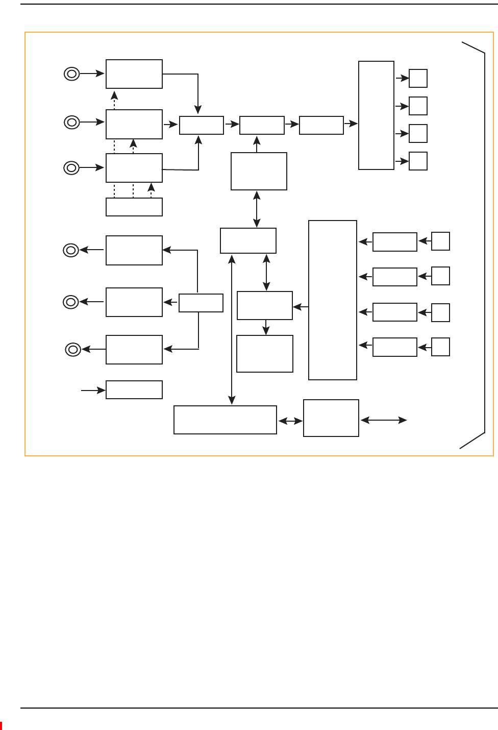
Fusion Wideband Main Hub Overview
InterReach Fusion Wideband Installation, Operation, and Reference Manual Page 31
D-620616-0-20 Rev H • TECP-77-044 Issue 7 • May 2013 © 2013 TE Connectivity Ltd.
Figure9.Main Hub Block Diagram
Downlink
RF In
Band 1
Downlink
RF In
Band 2
Downlink
RF In
Band 3
Uplink
RF Out
Band 1
Uplink
RF Out
Band 2
Uplink
RF Out
Band 3
Diplexer
Diplexer
i
RF to IF
Section B1
RF to IF
Section B2
RF to IF
Section B3
CAL Tone
IF to RF
Section B1
IF to RF
Section B2
IF to RF
Section B3
Power Supply
Single-Board Computer Alarm
Interface
IF Section IF to Optical
Optical
Splitter
Downlink
Optical
OUT
Clock,
FSK,
Pilot
Micro FSK
IF
Section
Piolt Det,
FSK
Combiner
Optical to IF
Optical to IF
Optical to IF
Optical to IF
Uplink
Optical
Input
Alarm
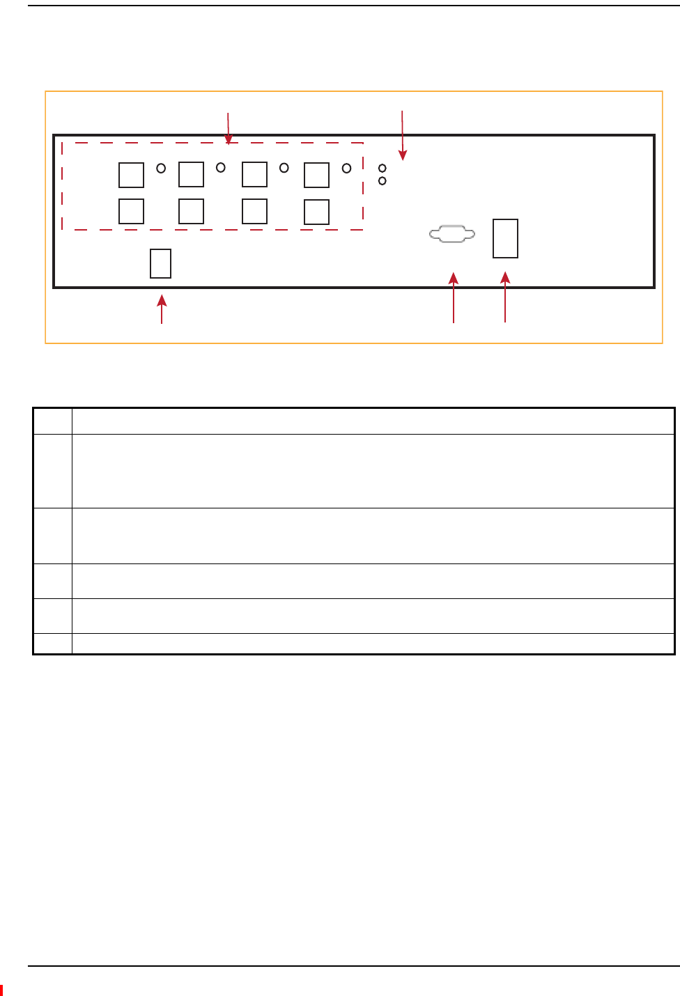
Fusion Wideband Main Hub
Page 32 InterReach Fusion Wideband Installation, Operation, and Reference Manual
© 2013 TE Connectivity Ltd D-620616-0-20 Rev H • TECP-77-044 Issue 7 • May 2013
FUSIONWIDEBANDMAINHUBFRONTPANEL
Figure10.Fusion Wideband Main Hub Front Panel
NOTE: TheFusionWidebandOnePortMainHub(PNs:FSN‐W1‐MH‐2‐1P,FSN‐W2‐MH‐3‐1P,
FSN‐W3‐MH‐1P,FSN‐W4‐MH‐1P,andFSN‐W5‐MH‐1P)configurationisacostreducedversionof
theFusionWidebandMainHubandsupportsonlyoneExpansionHub(upto8RAUs).
Ref # Description
1Four fiber optic ports (labeled PORT 1, PORT 2, PORT 3, PORT 4) with corresponding fiber port LEDs (one LED per port)
• One standard female SC/APC connector per port for MMF/SMF input (labeled UPLINK)
• One standard female SC/APC connector per port for MMF/SMF output (labeled DOWNLINK)
• One LED per port for port link status and downstream unit status
2One set of unit status LEDs
• One LED for unit power status (labeled POWER)
• One LED for unit status (labeled MAIN HUB STATUS)
3One 9-pin D-sub male connector for system remote dial-up communication and diagnostics using a modem (labeled
MODEM)
4One RJ-45 female connector for system communication and diagnostics using a PC/laptop with direct connect or using
a LAN switch (labeled ADMIN/LAN)
5Power switch
POWER
MAIN HUB
STATUS
UPLINK
DOWNLINK
PORT 1 PORT 2 PORT 3 PORT 4
POWER InterReach
Wideband Fusion
Main Hub
ADMIN LANMODEM
12
345 Unit is not shown to scale.

Fusion Wideband Main Hub Front Panel
InterReach Fusion Wideband Installation, Operation, and Reference Manual Page 33
D-620616-0-20 Rev H • TECP-77-044 Issue 7 • May 2013 © 2013 TE Connectivity Ltd.
OpticalFiberUplink/DownlinkPorts
Theopticalfiberuplink/downlinkportstransmitandreceiveopticalsignalsbetweentheMain
HubanduptofourExpansionHubsusingindustry‐standardSMForMMFcable.Therearefour
fiberportsonthefrontpaneloftheMainHub;oneportperExpansionHub.Eachfiberporthas
twofemaleSC/APCconnectors:
•OpticalFiberUplinkConnector—Thisconnector(labeledUPlink)isusedtoreceivethe
uplinkopticalsignalsfromanExpansionHub.
•OpticalFiberDownlinkConnector—Thisconnector(labeledDOWNlink)isusedto
transmitthedownlinkopticalsignalstoanExpansionHub.
CAUTION! ToavoiddamagingtheMainHub’sfiberconnectorports,useonlySC/APCfibercableconnectors
whenusingeithersingle‐modeormulti‐modefiber.Additionally,itiscriticaltosystem
performancethatonlySC/APCfiberconnectorsareusedthroughoutthefibernetwork,including
fiberdistributionpanels.
CommunicationsRS‐232SerialConnector
•RemoteMonitoring—Useastandardserialcabletoconnectamodemtothe9‐pinD‐sub
maleserialconnectorforremotemonitoringorconfiguring.ThecabletypicallyhasaDB‐9
femaleandaDB‐9femaleconnector.Refer“DB‐9toDB‐9NullModemCable”onpage201to
forthecablepinoutdiagram.
RemotemonitoringisalsoavailablebyconnectingtheRJ‐45(ADMIN/LAN)porttoaLAN
switchforremoteEthernetLANaccessordirectdial‐uprouteraccess.
•LocalMonitoring—UseacrossoverEthernetcable(PN‐4069‐ADB)toconnectalaptoporPC
totheRJ‐45femaleconnectorforlocalmonitoringorconfiguringusingtheAdminBrowser
residentsoftware.ThecabletypicallyhasaRJ‐45maleconnectoronbothends.Referto
“TCP/IPCross‐OverCable”onpage200forthecablepinout.
MainHubLEDIndicators
Theunit’sfrontpanelLEDsindicatefaultsandcommandedorfaultlockouts.TheLEDsdonot
indicatewarningsorwhetherthesystemtesthasbeenperformed.UsetheLEDstoprovidebasic
informationonly,orasabackupwhenyouarenotusingAdminBrowser.
Uponpowerup,theMainHubgoesthrougha20‐secondtesttochecktheLEDlamps.Duringthis
time,theLEDsblinkthroughthestatesshowninTable3‐1,lettingyouvisuallyverifythattheLED
lampsandthefirmwarearefunctioningproperly.Uponcompletionofinitialization,theLEDsstay
inoneofthefirsttwostatesshowninTable3‐1.
TheMainHubautomaticallysendstheprogrambandscommandtoallconnectedRAUs.A
mismatchedbandcausesafaultmessagetobedisplayedinAdminBrowserandplacestheRAUin
adisabledcondition.
NOTE: Referto“TroubleshootingUsingLEDs”onpage186fortroubleshootingusingtheLEDs.
NOTE: AdminBrowsershouldbeusedfortroubleshootingthesystem.OnlyuseLEDsforbackupor
confirmation.However,iftherearecommunicationproblemswithinthesystem,theLEDsmay
provideadditionalinformationthatisnotavailableusingAdminBrowser.

Fusion Wideband Main Hub
Page 34 InterReach Fusion Wideband Installation, Operation, and Reference Manual
© 2013 TE Connectivity Ltd D-620616-0-20 Rev H • TECP-77-044 Issue 7 • May 2013
UnitStatusLEDs
TheMainHubhasonepairofstatusLEDs,labeledpowerandstatus,whichcanbeinoneofthe
statesshowninTable29.TheseLEDscanbe:
Thereisnooffstatewhentheunit’spowerison.
FiberPortLEDs
TheMainHubhasonefiberportLEDforeachofthefourfiberports.TheLEDcanbeinoneofthe
statesshowninTable30onpage35.ThisLEDcanbe:
•Steadygreen
•Steadred
•Off—nocolor(validonlyduring90secondpowercycle)
•Flashingredat60PulsesperMinute(PPM)
Table29.FusionWidebandHubStatusLEDStates
LED State Indicates
•Green
•G
reen
• The Main Hub is connected to power and all power supplies are operating.
• The Main Hub is not reporting a fault; however, the system test may need to be performed
or a warning condition may exist. Use AdminBrowser to determine this.
•Green
•R
ed
• The Main Hub is connected to power and all power supplies are operating. Use
AdminBrowser to power status.
• The Main Hub is reporting a fault.
•Green
•Flashing green
• The Main Hub is connected to power and all power supplies are operating.
Use Admin Browser to determine power status.
• The Main Hub is reporting a lockout condition; flashes green at 60 Pulses per Minute
(PPM).
•Green
•R
ed
• The Main Hub is connected to power and all power supplies are operating.
• The Main Hub DL input signal level is too high; flashes red at 60 Pulses per Minute (PPM).
•Red
•R
ed
• One or more power supplies are out-of-specification.
•Green
•Red/Green
(alternating)
• After the System CPU is rebooted, the MH status LED blinks red/green while the system
tree data is built, power up system test is executed, and all units have their current status
updated.
• Should the MH status LED blink red/green after initial power up, either the System CPU
has rebooted or a component of the software has reset.
•Off
•Steadygreen
•Steadyred
•Flashingred(60ppm)
POWER
STATUS
POWER
STATUS
POWER
STATUS
POWER
STATUS
POWER
STATUS
POWER
STATUS
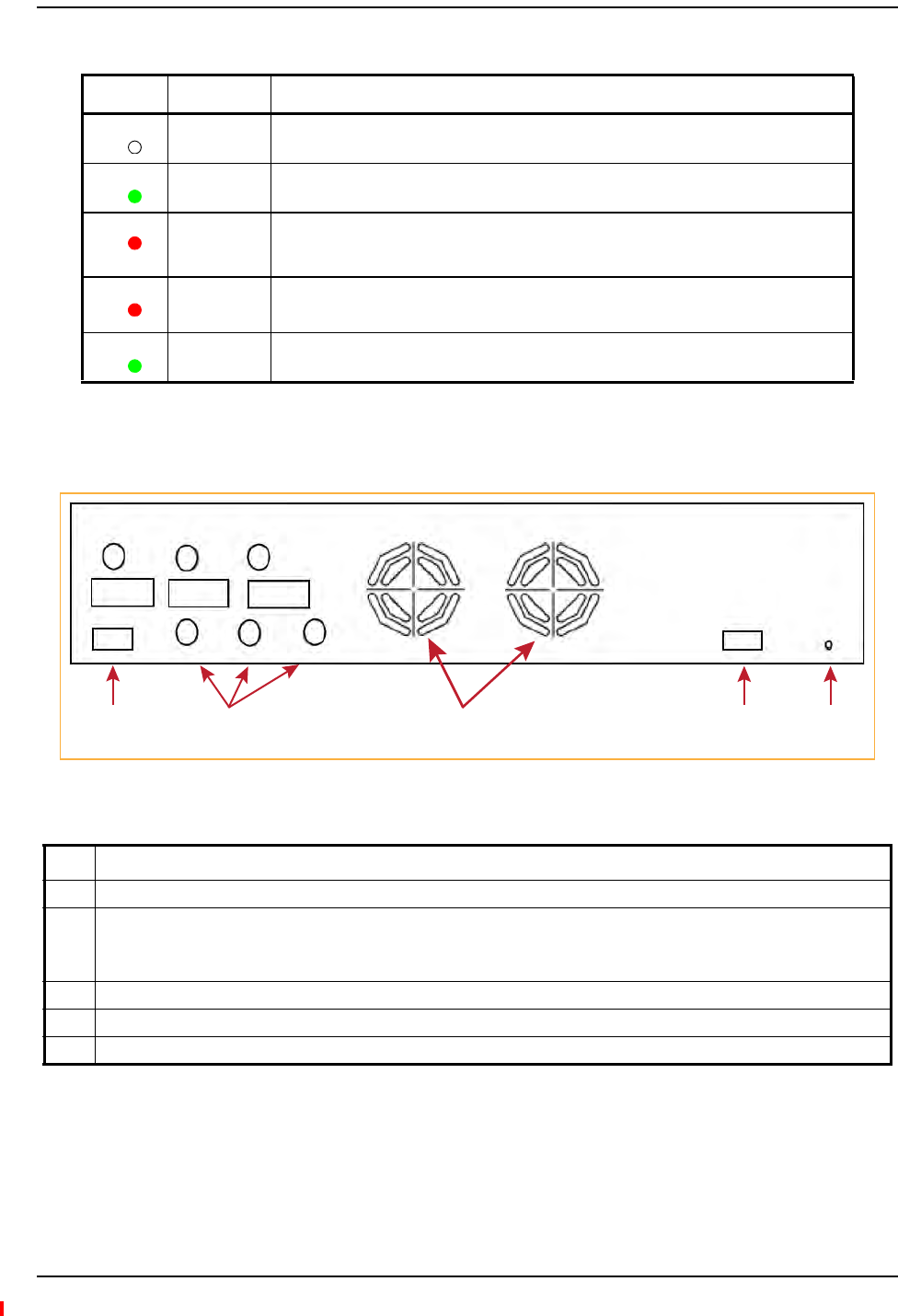
Fusion Wideband Main Hub Front Panel
InterReach Fusion Wideband Installation, Operation, and Reference Manual Page 35
D-620616-0-20 Rev H • TECP-77-044 Issue 7 • May 2013 © 2013 TE Connectivity Ltd.
FusionWidebandMainHubRearPanel
Figure11.Fusion Wideband Main Hub Rear Panel
Table30.FusionWidebandHubPortLEDStates
LED State Indicates
Off • The Expansion Hub is not connected.
Green
• The Expansion Hub is connected.
•There are no faults from the Expansion Hub or any connected RAU.
Red
(60 PPM)
• There was a loss of communications with the Expansion Hub.
Red
(Steady)
• The Expansion Hub is disconnected.
•The Expansion Hub or any connected RAU reported a fault.
Green
(60-ppm)
• The Expansion Hub or any connected RAU reported a lockout condition.
Ref # Description
1One 9-pin D-sub female connector labeled “Alarms” for contact alarm monitoring
2Three N-type, female connectors for each band (Band 1, Band 2, and Band 3):
• Uplink (labeled Ul1, Ul2, and UL3)
•Downlink (labeled DL1, Dl2, and DL3)
3Two air exhaust vents
4AC power cord connector
5Ground lug labeled “Ground” that connects the unit to frame ground
PORT
PORT
PORT
PORT
PORT
1 43
Unit is not shown to scale.
Alarms AC Power
Band 1 Band 2 Band 3
UL1 UL2 UL3
DL1 DL2 DL3
25

Fusion Wideband Main Hub
Page 36 InterReach Fusion Wideband Installation, Operation, and Reference Manual
© 2013 TE Connectivity Ltd D-620616-0-20 Rev H • TECP-77-044 Issue 7 • May 2013
FusionWidebandMainHubRearPanelConnectors
9‐pinD‐subConnector
The9‐pinD‐subconnector(labeledAlarms)providesacontactalarmforfaultandwarning
systemalarmmonitoring.Table31liststhepinfunctiononthe9‐pinD‐subconnector.
Thisinterfacecanbothgeneratetwosourcecontactalarms(FaultandWarning)andsense3
singleexternalalarmcontacts(AlarmSenseInput1through3).
N‐typeFemaleConnectors
Therearetwo50OhmN‐typeconnectorpairsforeachofthe3bandsontherearpaneloftheHub:
•ThedownlinkconnectorreceivesdownlinkRFsignalsfromarepeater,localbasestation,or
FlexWaveFocussystem.
•TheuplinkconnectortransmitsuplinkRFsignalstoarepeater,localbasestation,or
FlexWaveFocussystem.
CAUTION! TheuplinkanddownlinkportscannothandleaDCpowerfeedfromthelocalbasestation.IfDC
powerispresent,aDCblockmustbeusedortheFusionWidebandhubmaybedamaged.
Table31.9‐PinD‐SubPinConnectorFunctions
Pin Function
1Alarm Sense Input (DC Ground)
2Alarm Sense Input 3
3Alarm Sense Input 2
4Warning Source Contact (positive connection)
5Warning Source Contact (negative connection)
6DC Ground (common)
7Fault Source Contact (positive connection)
8Alarm Sense Input 1
9Fault Source Contact (negative connection)

Main Hub Specifications
InterReach Fusion Wideband Installation, Operation, and Reference Manual Page 37
D-620616-0-20 Rev H • TECP-77-044 Issue 7 • May 2013 © 2013 TE Connectivity Ltd.
MAINHUBSPECIFICATIONS
NOTE: TheFusionWidebandOnePortMainHub(PNs:FSN‐W1‐MH‐2‐1P,FSN‐W2‐MH‐3‐1P,
FSN‐W3‐MH‐1P,FSN‐W4‐MH‐1P,andFSN‐W5‐MH‐1P)configurationisacostreducedversionof
theFusionWidebandMainHubandsupportsonlyoneExpansionHub(upto8RAUs).
Table32.MainHubSpecifications
Specification Description
Enclosure Dimensions (a)
(H x W x D)
89 mm x 438 mm x 381 mm
3.5 in. x 17.25 in. x 15 in.
2U
Weight <5.5 kg
<12 lb
Operating Temperature 0° to +45°C
+32° to +113°F
Non-operating Temperature –20° to +85°C
–4° to +185°F
Operating Humidity, non-condensing 5% to 95%
External Alarm Connector (contact closure) One 9-pin D-sub, female
Maximum: 40 mA @ 40V DC
Typical: 4 mA @ 12V DC
ADMIN/LAN Interface Connector One RJ-45, female
One 9-pin D-sub, male for optional modem
Fiber Connectors Four Pair, SC/APC (b)
RF Connectors Four N(c), female (50 Ohm), 1 Downlink/Uplink pair per band
LED Fault and Status Indicators Unit Status (One pair):
•Power
•Main Hub Statu
Downstream Unit/Link Status (One per fiber port):
• Link/E-Hub/RAU
AC Power Rating 100/240V AC, 1A, 50-60 Hz
Operating Range: 90-132V AC/170-250V AC auto-ranging
Power Consumption 30 Watts
MTBF 133,829 hours
a Excluding angle brackets for the 19” rack mounting of the Hub.
b It is critical to system performance that only SC/APC fiber connectors are used throughout the fiber network, including fiber
distribution panels.
c 6 N, female connectors for FSN-W2-MH-1, FSN-W2-MH-3, FSN-W4-MH-1, and FSN-W5-MH-1

Fusion Wideband Main Hub
Page 38 InterReach Fusion Wideband Installation, Operation, and Reference Manual
© 2013 TE Connectivity Ltd D-620616-0-20 Rev H • TECP-77-044 Issue 7 • May 2013
FAULTS,WARNINGS,ANDSTATUSMESSAGES
TheFusionWidebandMainHubmonitorsandreportschangesoreventsinsystemperformance
to:
•Ensurethatfiberreceivers,amplifiersandIF/RFpathsarefunctioningproperly.
•EnsurethatExpansionHubsandRemoteAccessUnitsareconnectedandfunctioning
properly.
Events
Aneventisclassifiedasfault,warning,orstatusmessage.
•Faultsareserviceimpacting.
•Warningsindicateapossibleserviceimpact.
•Statusandinformationalmessagesaregenerallynotserviceimpacting.
TheFusionWidebandMainHubperiodicallyqueriesattachedExpansionHubandRemoteAccess
Unitsfortheirstatus.BothfaultsandwarningsarereportedtoaconnectedPC/laptoprunninga
standardbrowsercommunicatingwiththeAdminBrowsersoftware.Onlyfaultsareindicatedby
thefaceplateLEDs.
Formoreinformationregardingtheevents,referto:
•“AppendixC:Faults,Warnings,StatusTablesforFusion,FusionWideband,FusionSingleStar”
onpage209for
–MainHubfaults
–MainHubwarnings
–MainHubstatusmessages
•“Maintenance,Troubleshooting,andTechnicalAssistance”onpage181fortroubleshooting
MainHubLEDs.
ViewPreference
AdminBrowser1.0orhigherenablesyoutoselect(usingthescreenshowninFigure12)thetype
ofeventstobedisplayed.

Faults, Warnings, and Status Messages
InterReach Fusion Wideband Installation, Operation, and Reference Manual Page 39
D-620616-0-20 Rev H • TECP-77-044 Issue 7 • May 2013 © 2013 TE Connectivity Ltd.
Figure12.Preferences Check Boxes
Tomodifythesetting,usingAdminBrowser,selectAlarmsgSetAlarmPreferenceandselectthe
desiredchoice.AfteryouclickOK,AdminBrowserrefreshesandupdatesthetreeviewaccording
tothenewsetting.
NOTE: ThesettingisstrictlyvisualandonlyinAdminBrowser.Thereisnoaffectonthehardwareitself.
Bydefault,theeventfilteringissetto“EnableviewingofFaultsonly”.
TheonlyexceptiontowhentheeventfilteringisignoredisduringtheInstall/Configure
command.Alleventsaredisplayedregardlessoftheeventfilteringsetting.Thisensuresasmooth
installation.

Fusion Wideband Main Hub
Page 40 InterReach Fusion Wideband Installation, Operation, and Reference Manual
© 2013 TE Connectivity Ltd D-620616-0-20 Rev H • TECP-77-044 Issue 7 • May 2013

InterReach Fusion Wideband Installation, Operation, and Reference Manual Page 41
D-620616-0-20 Rev H • TECP-77-044 Issue 7 • May 2013 ©2013 TE Connectivity Ltd.
FUSIONWIDEBANDEXPANSIONHUB
ExpansionHubOverview ....................................................................................................................................42
ExpansionHubFrontPanel .................................................................................................................................. 44
75OhmTypeFConnectors .................................................................................................................................. 45
ManufacturingRS‐232SerialConnector .............................................................................................................. 45
ConsolePort .....................................................................................................................................................................45
LocalMonitoring...............................................................................................................................................................45
OpticalFiberUplink/DownlinkConnectors.......................................................................................................... 45
LEDIndicators....................................................................................................................................................... 46
UnitStatusandDL/ULStatusLEDs ...................................................................................................................................46
RJ‐45PortLEDs .................................................................................................................................................................48
ExpansionHubRearPanel ..................................................................................................................................49
Faults,Warnings,andStatusMessages...............................................................................................................50
ExpansionHubSpecifications .............................................................................................................................51
Topics Page
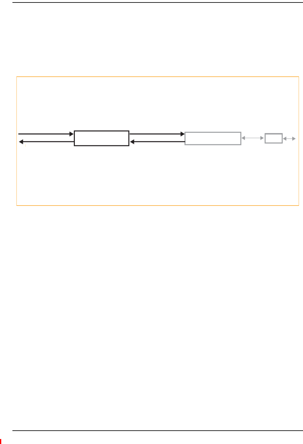
Fusion Wideband Expansion Hub
Page 42 InterReach Fusion Wideband Installation, Operation, and Reference Manual
© 2013 TE Connectivity Ltd D-620616-0-20 Rev H • TECP-77-044 Issue 7 • May 2013
EXPANSIONHUBOVERVIEW
TheExpansionHubactsaninterfacebetweentheMainHubandtheRemoteAccessUnit(s)by
convertingopticalsignalstoelectricalsignalsandviceversa,asshowninFigure13.Italso
suppliescontrolsignalsandDCpowertooperatetheRemoteAccessUnit(s)aswellaspassing
statusinformationfromtheRAUstotheMainHub.
Figure13.Expansion Hub in a Fusion Wideband System
Downlink Path: The Expansion Hub receives downlink (Band 1, 2, and 3) optical signals from the Main Hub using fiber optic
cable. It converts the signals to electrical and sends them to up to eight Remote Access Units (RAUs) using CATV cables. The
Expansion Hub also receives configuration information from the Main Hub using the fiber optic cable and relays it to the RAUs
using CATV cable.
Uplink Path: The Expansion Hub receives uplink (Band 1, 2, and 3) IF signals from up to eight RAUs using CATV cables. It
converts the signals to optical and sends them to a Main Hub using fiber optic cable.
The Expansion Hub also receives RAU status information using CATV cable and sends it and its own status information to the
Main Hub using the fiber optic cable.
RF1, 2, and 3
Downlink to Main Hub
Uplink from Main Hub
RF1, 2, and 3
Downlink to Main Hub
Uplink from Main Hub
Fusion Wideband
Main Hub
Fusion Wideband
Main Hub
RAU
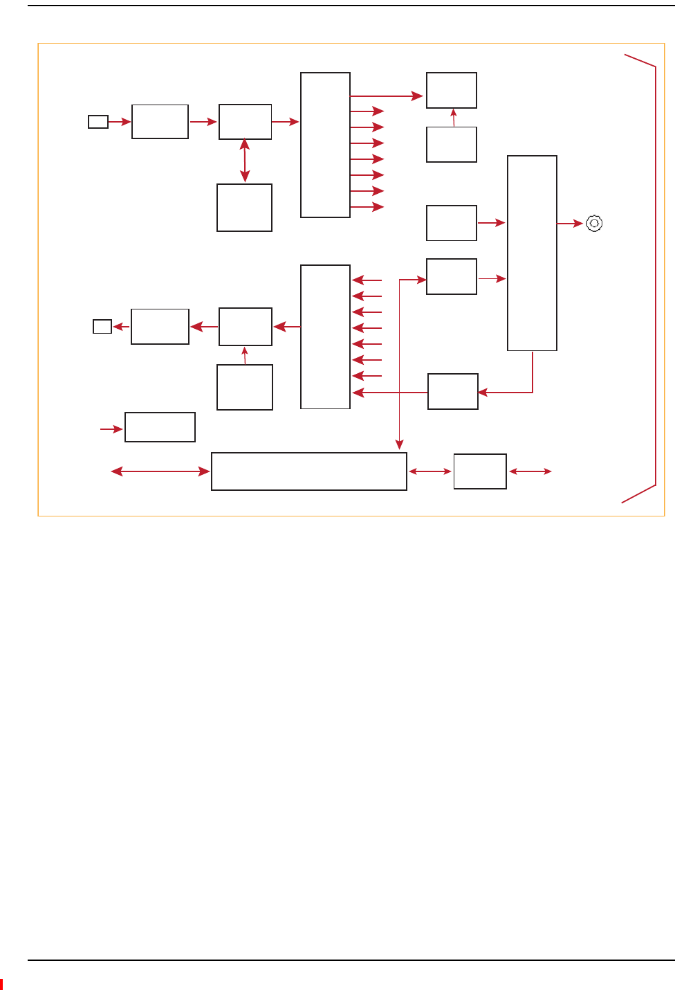
Expansion Hub Overview
InterReach Fusion Wideband Installation, Operation, and Reference Manual Page 43
D-620616-0-20 Rev H • TECP-77-044 Issue 7 • May 2013 © 2013 TE Connectivity Ltd.
Figure14.Expansion Hub Block Diagram
Downlink
Optical In
Optical
to IF
IF
Section
Clock,
FSK,
Pilot Det
Uplink
Optical Out
IF to
Optical
AC
Input
Ethernet
Interface
Power Supply
IF
Section
Regerated
UL Pilot
8 Way
Spliiter
8 Way
Spliiter
Micro Controller
IF
Section
IF
Section
Alarm
Interface
IF
Detector
DC
Power
FSK
Diplexer
CATV
Connector
Signals
DL IF
UL IF
DC Power
FSK
Ref Clock
Alarm
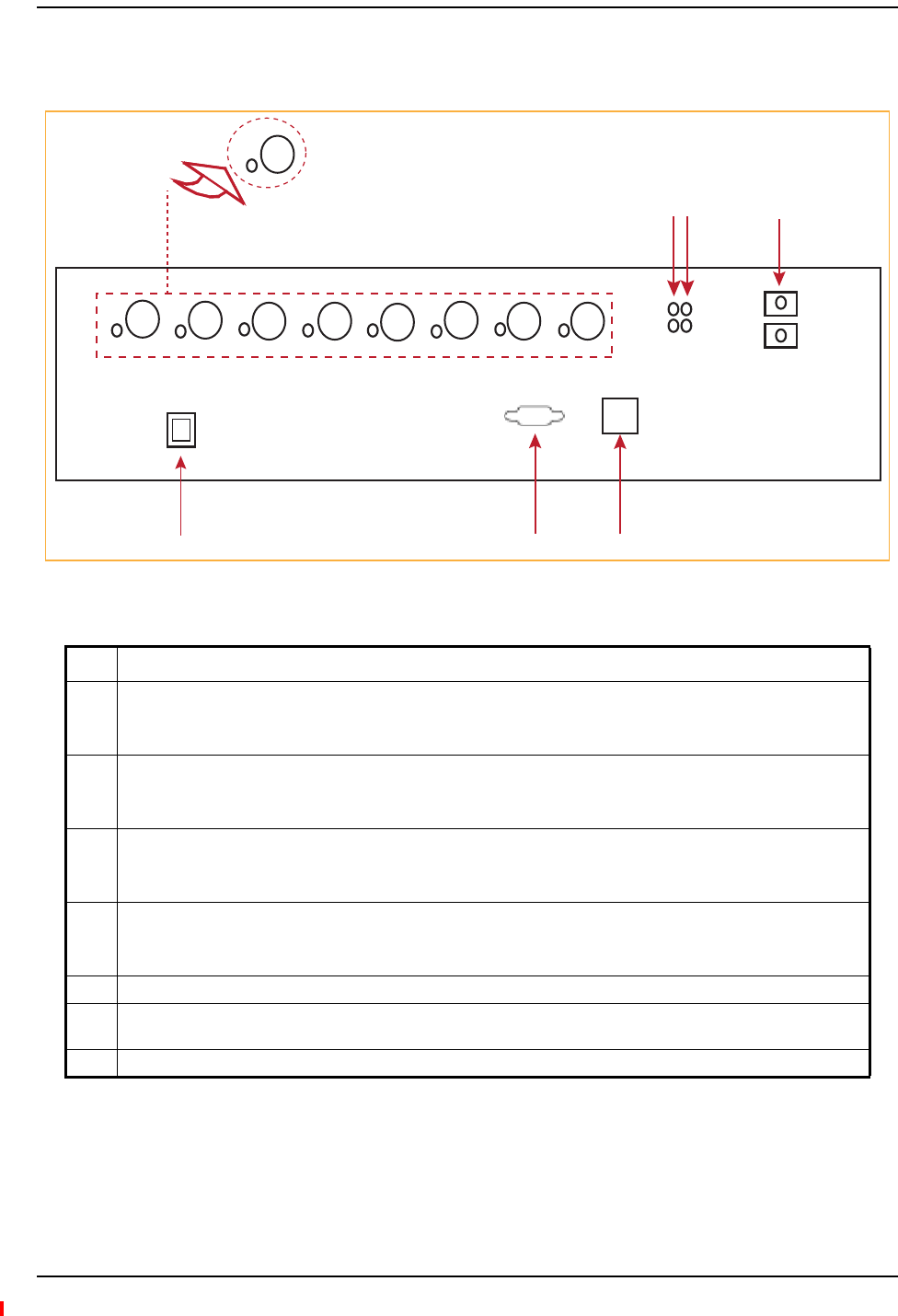
Fusion Wideband Expansion Hub
Page 44 InterReach Fusion Wideband Installation, Operation, and Reference Manual
© 2013 TE Connectivity Ltd D-620616-0-20 Rev H • TECP-77-044 Issue 7 • May 2013
ExpansionHubFrontPanel
Figure15.Expansion Hub Front Panel
Ref # Description
1One port LED and connector pair for 8 ports (labeled Port n, where n = 1 - 8):
• One port LED per type F connector port for link status and downstream RAU status (8 pair total).
• Eight CATV cable, type F connectors
2One pair of unit status LEDs
• One LED for unit power status (labeled POWER)
•One LED for unit status (labeled E-HUB STATUS)
3One set of fiber status LEDs
• One LED for fiber uplink status (labeled UL STATUS)
•One LED for fiber downlink status (labeled DL STATUS)
4One fiber optic port which has two connectors
• One standard female SC/APC connector for MMF/SMF output (labeled Uplink)
• One standard female SC/APC connector for MMF/SMF input (labeled Downlink)
5One 9-pin D-sub male connector for TE factory testing (labeled Console)
6One RJ-45 female connector for system communication and diagnostics using a PC/laptop with direct connect or
using a LAN switch (labeled Admin/Lan)
7Power Switch
1
Unit is not shown to scale.
Port 1
CONSOLE
Port 2 Port 3 Port 4 Port 5 Port 6 Port 7 Port 8
UPLINK
DOWNLINK
InterReach Fusion
Expansion Hub
ADMIN/LAN
POWER
EH STATUS
DL STATUS
UL STATUS
Port 1
2 3 4
5
6
7

Expansion Hub Overview
InterReach Fusion Wideband Installation, Operation, and Reference Manual Page 45
D-620616-0-20 Rev H • TECP-77-044 Issue 7 • May 2013 © 2013 TE Connectivity Ltd.
75OhmTypeFConnectors
TheeighttypeFconnectorsontheExpansionHubarefortheCATVcablesusedtotransmitand
receivesignalstoandfromRAUs.Useonly75ohmtypeFconnectorsontheCATVcable.
TheCATVcablealsodeliversDCelectricalpowertotheRAUs.TheExpansionHub’sDCvoltage
outputis54VDCnominal.AcurrentlimitingcircuitprotectstheHubifanyportdrawsexcessive
power.
NOTE: Forsystemperformance,itisimportanttouseonlylowlosssolidcoppercenterconductorCATV
cablewithqualitytypeFconnectorsthatusecaptivecenterpinconnectors.Referto“Appendix
A:CablesandConnectors”onpage191forapprovedcablesandconnectors.
ManufacturingRS‐232SerialConnector
ConsolePort
ThisconsoleportisonlyusedbyTEmanufacturingtestpurposes.DONOTCONNECTANYTHING
TOIT.
LocalMonitoring
UseacrossoverEthernetcable(PN‐4069‐ADB)todirectlyconnectalaptoporPCtotheRJ‐45
femaleconnectorforlocalmonitoringorconfiguringtheExpansionHubandassociatedRAUs
usingtheAdminBrowser‐EHresidentsoftware.ThecabletypicallyhasaRJ‐45maleconnectoron
bothends.Referto“TCP/IPCross‐OverCable”onpage200forthecablepinoutandthe
AdminBrowsermanual.
OpticalFiberUplink/DownlinkConnectors
Theopticalfiberuplink/downlinkporttransmitsandreceivesopticalsignalsbetweenthe
ExpansionHubandtheMainHubusingindustry‐standardSMForMMFcable.Thefiberporthas
twofemaleSC/APCconnectors:
•OpticalFiberUplinkConnector—Thisconnector(labeledUPLINK)isusedtotransmit
(output)uplinkopticalsignalstotheMainHub.
•OpticalFiberDownlinkConnector—Thisconnector(labeledDOWNLINK)isusedtoreceive
(input)downlinkopticalsignalsfromtheMainHub.
CAUTION! ToavoiddamagingtheExpansionHub’sfiberconnectorports,useonlySC/APCfibercable
connectors.Additionally,useonlySC/APCfiberconnectorsthroughoutthefibernetwork,
includingfiberdistributionpanels.Thisiscriticalforensuringsystemperformance.
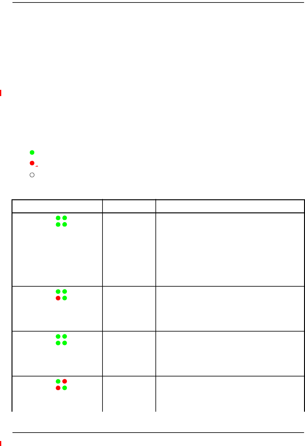
Fusion Wideband Expansion Hub
Page 46 InterReach Fusion Wideband Installation, Operation, and Reference Manual
© 2013 TE Connectivity Ltd D-620616-0-20 Rev H • TECP-77-044 Issue 7 • May 2013
LEDIndicators
Theunit’sfrontpanelLEDsindicatefaultconditionsandcommandedorfaultlockouts.TheLEDs
donotindicatewarningsorwhetherthesystemtesthasbeenperformed.OnlyusetheLEDsto
providebasicinformationorasabackupwhenyouarenotusingAdminBrowser.
Uponpowerup,theExpansionHubgoesthroughafive‐secondtesttochecktheLEDlamps.
Duringthistime,theLEDsblinkthroughthestatesshowninTable4‐2,lettingyouvisuallyverify
thattheLEDlampsandthefirmwarearefunctioningproperly.
NOTE: Referto“Maintenance,Troubleshooting,andTechnicalAssistance”onpage181for
troubleshootingusingtheLEDs.
UnitStatusandDL/ULStatusLEDs
TheExpansionHubunitstatusandDL/ULstatusLEDscanbeinoneofthestatesshownin
Table4‐1.TheseLEDscanbe:
Steady green
Stead red
Off
Table33.ExpansionHubUnitStatusandDL/ULStatusLEDStates
LED State Indicates
Green/Green
Green/Green
• The Expansion Hub is connected to power and all power
supplies are operating.
• The Expansion Hub is not reporting a fault or lockout condition;
but the system test may need to be performed or a warning
condition could exist (use AdminManager to determine this).
• Optical power received is above minimum (the Main Hub is
connected) although the cable optical loss may be greater than
recommended maximum.
• Optical power transmitted (uplink laser) is normal and
communications with the Main Hub are normal.
Green/Green
Red/Green
• Optical power received is above minimum (the Main Hub is
connected) although the cable optical loss may be greater than
recommended maximum.
• Optical power transmitted (uplink laser) is normal and
communications with the Main Hub are normal.
• The Expansion Hub is reporting a fault.
Green/Green
Green/Green
(60-ppm)
• Optical power received is above minimum (the Main Hub is
connected) although the cable optical loss may be greater than
recommended maximum.
• Optical power transmitted (uplink laser) is normal and
communications with the Main Hub are normal.
• The Expansion Hub is reporting a commanded lockout.
Green/Red
Red/Green
• A fault condition was detected; optical power received is below
minimum.
(The Main Hub is not connected, is not powered, or the Main
Hub’s downlink laser has failed, or the downlink fiber is
disconnected or damaged.)
POWER
EH STATUS DL STATUS
UL STATUS
POWER
EH STATUS DL STATUS
UL STATUS
POWER
EH STATUS DL STATUS
UL STATUS
POWER
EH STATUS DL STATUS
UL STATUS

Expansion Hub Overview
InterReach Fusion Wideband Installation, Operation, and Reference Manual Page 47
D-620616-0-20 Rev H • TECP-77-044 Issue 7 • May 2013 © 2013 TE Connectivity Ltd.
Green/Green
Red/Red
• The Expansion Hub is reporting a fault condition.
• Optical power received is above minimum (Main Hub is
connected) although the cable optical loss may be greater than
recommended maximum.
• Optical power transmitted is below minimum (Expansion Hub
uplink laser has failed; unable to communicate with Main Hub).
UL STATUS LED state must be checked within the first 90
seconds after power on. If initially green, then red after 90
seconds, it means that there is no communication with the
Main Hub. If red on power up, replace the Expansion Hub.
Green/Red
Red/Red
• Optical power received is below minimum (the Main Hub is not
connected, is not powered, or the Main Hub’s downlink laser
has failed, or the downlink fiber is disconnected or damaged.)
• Optical power transmitted is below minimum (the Expansion
Hub uplink laser has failed; is unable to communicate with the
Main Hub). UL STATUS LED state must be checked within the
first 90 seconds after power on. If initially green, then red after
90 seconds, it means that there is no communication with the
Main Hub. If red on power up, the uplink laser has failed,
replace the Expansion Hub.
Green/Off
Green/Off
• Expansion Hub is in factory test mode, return it to the factory.
Red/Don’t Care
Red/Don’t Care
• One or more power supplies are out of specification. The hub
needs to be replaced.
Green/Red
Off/Off
• Expansion Hub failure. The Hub must be replaced.
Table33.ExpansionHubUnitStatusandDL/ULStatusLEDStates(Cont.)
LED State Indicates
POWER
EH STATUS DL STATUS
UL STATUS
POWER
EH STATUS DL STATUS
UL STATUS
POWER
EH STATUS DL STATUS
UL STATUS
POWER
EH STATUS DL STATUS
UL STATUS
POWER
EH STATUS DL STATUS
UL STATUS

Fusion Wideband Expansion Hub
Page 48 InterReach Fusion Wideband Installation, Operation, and Reference Manual
© 2013 TE Connectivity Ltd D-620616-0-20 Rev H • TECP-77-044 Issue 7 • May 2013
RJ‐45PortLEDs
TheExpansionHubhasaportLED,labeledPORT,foreachoftheeight75Ohm,TypeFports.The
portLEDscanbeinoneofthestatesshowninTable4‐2.TheseLEDscanbe:
Off
Steady green
Stead red
Off—no color (valid only during 90 second power cycle)
Flashing red at 60 Pulses per Minute (PPM)
Table34.FusionExpansionHubPortLEDStates
LED State Indicates
Off The RAU is not connected.
Green The RAU is connected or there are no faults from the RAU.
Flashing red Flashing red at 60 Pulses per Minute (PPM).
•The RAU was disconnected.
•The RAU is not communicating.
•The RAU port power is tripped.
Red The RAU is disconnected or the RAU is reporting a fault.
Flashing
green
Flashing green at 60 Pulses per Minute (PPM).
•The RAU is disconnected.
•The RAU is reporting a lockout condition.
PORT
PORT
PORT
PORT
PORT
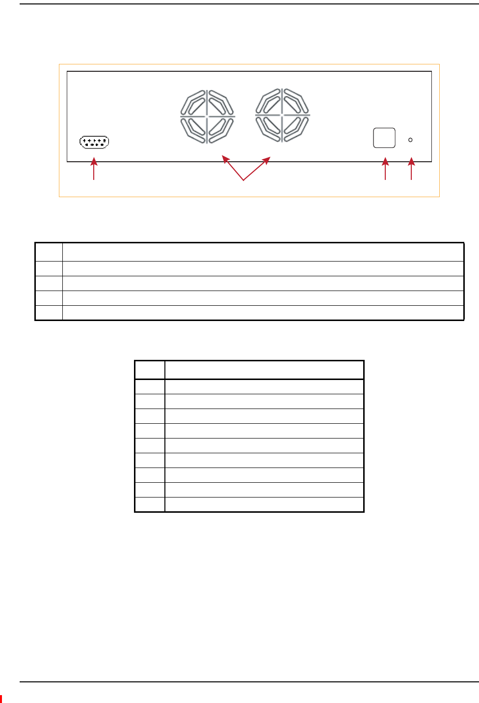
Expansion Hub Rear Panel
InterReach Fusion Wideband Installation, Operation, and Reference Manual Page 49
D-620616-0-20 Rev H • TECP-77-044 Issue 7 • May 2013 © 2013 TE Connectivity Ltd.
EXPANSIONHUBREARPANEL
Figure16.Expansion Hub Rear Panel
Thisinterfacecanmonitorthreesingleexternalalarmcontacts(AlarmSenseInput1This
interfacemonitorstheoutputcontactclosuresfromaUniversalPowerSupply(UPS).Verifythe
outputcontactclosurestate(normallyclosedornormallyopen)oftheUPS,andsetthe
appropriatecontactdefinitionusingAdminBrowser.
•Faultsareserviceimpacting.
•Warningsindicateapossibleserviceimpact.
•Statusmessagesaregenerallynotserviceimpacting.
Ref # Description
1AC power cord connector
2Two air exhaust vents
3One 9-pin D-sub female connector labeled ALARMS for contact alarm monitoring; for pinouts, see Table 35
4Ground lug labeled GROUND for connecting unit to frame ground
Table35.9‐PinD‐SubPinConnectorFunctions
Pin Function
1Alarm Sense Input (DC Ground)
2Alarm Sense Input 3
3Alarm Sense Input 2
4N/C
5N/C
6DC Ground (common)
7N/C
8Alarm Sense Input 1
9N/C
AC POWER
ALARMS GND
1234

Fusion Wideband Expansion Hub
Page 50 InterReach Fusion Wideband Installation, Operation, and Reference Manual
© 2013 TE Connectivity Ltd D-620616-0-20 Rev H • TECP-77-044 Issue 7 • May 2013
FAULTS,WARNINGS,ANDSTATUSMESSAGES
BothfaultandwarningconditionsoftheExpansionHubandattachedRAUsarereportedtothe
MainHub.OnlyfaultsareindicatedbyLEDs.
Formoreinformation,referto“AppendixC:Faults,Warnings,StatusTablesforFusion,Fusion
Wideband,FusionSingleStar”onpage209.
NOTE: YoucanselectwhattypeofeventsAdminBrowserdisplays.Referto“ViewPreference”on
page38.

Expansion Hub Specifications
InterReach Fusion Wideband Installation, Operation, and Reference Manual Page 51
D-620616-0-20 Rev H • TECP-77-044 Issue 7 • May 2013 © 2013 TE Connectivity Ltd.
EXPANSIONHUBSPECIFICATIONS
Table36.ExpansionHubSpecifications
Specification Description
Enclosure Dimensions (H W D) 89 mm x 438 mm x 381 mm
3.5 in. x 17.25 in. x 15 in.
2U
Weight < 6.6 kg
< 14.5 lb.
Operating Temperature 0° to +45°C
+32° to +113°F
Non-operating Temperature –20° to +85°C
–4° to +185°F
Operating Humidity, non-condensing 5% to 95%
CATV Connectors (a) 8 F, female (CATV - 75 Ohm)
Fiber Connectors (b) 1 Pair, SC/APC
LED Alarm and Status Indicators Unit Status (1 pair):
•POWER
• E-HUB STATUS
Fiber Link Status (1 pair):
• DL STATUS
•UL STATUS
Port Status (1 pair per CATV port):
•Link/RAU
External Alarm Connector (contact sense
monitor)
1 9-pin D-sub, female
AC Power (Volts) (47–63 Hz) Rating: 100/240V AC, 6A, 50-60 Hz
Operating Range: 90-132V AC/170-250V AC auto-ranging
Power Consumption (W) 4 RAUs: 290 typical, 360 maximum
8 RAUs: 500 typical, 630 maximum
MTBF 54,477 hours
a It is important that you use only recommended CATV 75 Ohm cable with quality F connectors.
b It is critical to system performance that only SC/APC fiber connectors are used throughout the fiber network,
including fiber distribution panels.

Fusion Wideband Expansion Hub
Page 52 InterReach Fusion Wideband Installation, Operation, and Reference Manual
© 2013 TE Connectivity Ltd D-620616-0-20 Rev H • TECP-77-044 Issue 7 • May 2013

InterReach Fusion Wideband Installation, Operation, and Reference Manual Page 53
D-620616-0-20 Rev H • TECP-77-044 Issue 7 • May 2013 ©2013 TE Connectivity Ltd.
REMOTEACCESSUNIT
Overview............................................................................................................................................................54
RemoteAccessUnitConnectors .........................................................................................................................57
50OhmType‐NConnector................................................................................................................................... 57
75OhmType‐FConnector ................................................................................................................................... 57
RAULEDIndicators .............................................................................................................................................58
StatusLEDs ........................................................................................................................................................... 58
FaultsandWarnings ...........................................................................................................................................59
RemoteAccessUnitSpecifications......................................................................................................................60
Topics Page
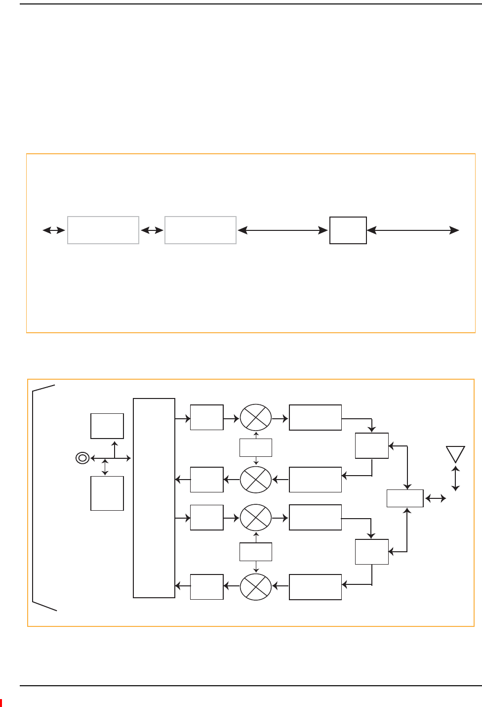
Remote Access Unit
Page 54 InterReach Fusion Wideband Installation, Operation, and Reference Manual
© 2013 TE Connectivity Ltd D-620616-0-20 Rev H • TECP-77-044 Issue 7 • May 2013
OVERVIEW
TheRemoteAccessUnit(RAU)isanactivetransceiverthatconnectstoanExpansionHubusing
industry‐standardCATVcable,whichdeliversRFsignals,configurationinformation,and
electricalpowertotheRAU.
AnRAUpassesconverted1FtoRF(Downlink)andconvertedRFto1F(Uplink)signalsbetween
anExpansionHubandanattachedpassiveantennawherethesignalsaretransmittedtowireless
devicesasshowninFigure17.
Figure17.Remote Access Unit in a Fusion Wideband System
Figure18.Remote Access Unit Block Diagram (Multiband)
Downlink Path: The RAU receives downlink IF signals from a Fusion Wideband Hub using 75 Ohm CATV cable. It converts
the signals to RF and sends them to a passive RF antenna using 50 Ohm coaxial cable. Also, the RAU receives configuration
information from the Fusion Wideband Hub using the 75 Ohm CATV cable.
Uplink Path: The RAU receives uplink RF signals from a passive RF antenna using 50 Ohm coaxial cable. It converts the
signals to IF and sends them to a Fusion Wideband Hub using 75 Ohm CATV cable. Also, the RAU sends its status information
to the Fusion Wideband Hub using CATV cable.
The RAU receives 54VDC power from the Fusion Wideband Hub port through the 75 Ohm CATV cable center pin.
Downlink
to RAU
Uplink
from RAU
Fusion Wideband
Main Hub RAU
Fusion Wideband
Main Hub
Downlink
to antenna
Uplink from
antenna
Diplexer
Gain
Control
Gain
Control
Gain
Control
Gain
Control
DC
Power
FSK
&
Micro
Gain, RF Filter &
Power Amplifier
PLL
PLL
Gain & RF Filter
Gain, RF Filter &
Power Amplifier
Gain & RF Filter
Band 1
Diplexer
Band 2
Diplexer
Diplexer RF
Connector
CATV
Connector
Signals
DL IF
UL IF
DC Power
FSK
Ref Clock
Band 1/3*
Band 2
* For FSN-W2-80519-1 RAU when Band 3 is active.

Overview
InterReach Fusion Wideband Installation, Operation, and Reference Manual Page 55
D-620616-0-20 Rev H • TECP-77-044 Issue 7 • May 2013 © 2013 TE Connectivity Ltd.
TheFusionWidebandRAUsaremanufacturedtoaspecificsetofbands:one60MHzBand1(split
intotwosub‐bands1Aand1BfortheFSN‐W2‐808519‐1RAU),andone75MHzBand2.Table5‐1
liststheFusionWidebandRAUs,theFusionWidebandBand,andthefrequencybandstheycover.
Table37.FrequencyBandsCoveredbyFusionWidebandRAUs
Fusion Wideband RAU Part Number Fusion
Wide-
band
Band
RF Passband
Downlink
(MHz)
Uplink
(MHz)
MAIN HUB/
RAU Band
RAU
Band-
width
2100/1800 FSN-W1-2118-1 2100 2110-2170 1920-1980 1 60 MHz
2100 HP/1800 HP FSN-W1-2118-1-HP 1800 1805-1880 1710-1785 2 75 MHz
2100 High Power
(single-band RAU)
FSN-W1-21HP-1 2100 2110-2170 1920-1980 1 60 MHz
1900/AWS FSN-W1-1921-1 1900 (A-F) 1930-1990 1850-1910 1 60 MHz
AWS 2110-2155 1710-1755 2 45 MHz
800/850/1900 FSN-W2-808519-1 800 851-869 806-824 1 (sub-band 1A) 18 MHz
850 869-894 824-849 3 (sub-band 1B) 25 MHz
1900 (A-F) 1930-1990 1850-1910 2 60 MHz
700/AWS FSN-W2-7021-1 700
(Upper C)
746-757 776-787 1 (sub-band 1A) 11 MHz
700
(Lower
ABC)
728-746 698-716 3 (sub-band 1B) 18 MHz
AWS 2110-2155 1710-1755 2 45 MHz
700/700 MIMO (Upper C) FSN-W2-7575-1 700
(Upper C)
746-757 776-787 1 (sub- band 1A) 11 MHz
700
(Upper C)
746-757 776-787 3 (sub- band 1B) 11 MHz
700/700 MIMO (Lower ABC) FSN-W2-7070-1 700
(Lower
ABC)
728-746 698-716 1 (sub- band 1A) 18 MHz
700
(Lower
ABC)
728-746 698-716 3 (sub- band 1B) 18 MHz
700 ABC/AWS HP/AWS HP FSN-W4-702121-1-HP AWS 2110-2155 1710-1755 1 (sub-band 1A) 45 MHz
700
(Lower
ABC)
728-746 698-716 3 (sub-band 1B) 18 MHz
AWS 2110-2155 1710-1755 245 MHz
700 UC/AWS HP/AWS HP FSN-W4-752121-1-HP AWS 2110-2155 1710-1755 1 (sub-band 1A) 45 MHz
700
(Upper C)
746-757 776-787 3 (sub-band 1B) 11 MHz
AWS 2110-2155 1710-1755 2 45 MHz
850/1900 HP/AWS HP FSN-W5-851921-1-HP AWS 2110-2155 1710-1755 1
(sub-band 1A)
45 MHz
850 869-894 824-849 3
(sub-band 1B)
25 MHz
1900 (A -
G)
1930-1995 1850-1915 2 65 MHz

Remote Access Unit
Page 56 InterReach Fusion Wideband Installation, Operation, and Reference Manual
© 2013 TE Connectivity Ltd D-620616-0-20 Rev H • TECP-77-044 Issue 7 • May 2013
2500/2500 FSN-2500-2-WMAX 2500 2496-2690 2496-2690 1 30 MHz
2500 2496-2690 2496-2690 2 30 MHz
2600/2600 FSN-W3-2626-1 2600 2620-2690 2500-2570 1 70 MHz
2600 2620-2690 2500-2570 2 70 MHz
Table38.SystemGain(Loss)RelativetoCATVCableLength
Cable
Type
CommScope
Part Number
Plenum
Rated
Solid Copper
Conductor
Copper Clad
Conductor
Zero-loss RF
Maximum
Length
(meters)
DistanceRF is
10dB Below
Input RF
(meters)
RG-59 2065V Yes X 130 180
2022V Yes X 100 100*
5572R No X 95 95*
5565 No X 130 180
RG-6 2279V Yes X 140 190
2275V Yes X 140 150*
5726 No X 140 140*
5765 No X 140 190
RG-11 2293K Yes X 235 320
2285K Yes X 235 300*
5913 No X 235 300*
* Exceeding the distance of copper-clad cable will result in the attached RAU becoming non-functional. If
the distance of a cable run is at its maximum and is of concern, TE recommends the use of solid copper
cable to ensure successful operation
Table37.FrequencyBandsCoveredbyFusionWidebandRAUs(Cont.)
Fusion Wideband RAU Part Number Fusion
Wide-
band
Band
RF Passband
Downlink
(MHz)
Uplink
(MHz)
MAIN HUB/
RAU Band
RAU
Band-
width

Remote Access Unit Connectors
InterReach Fusion Wideband Installation, Operation, and Reference Manual Page 57
D-620616-0-20 Rev H • TECP-77-044 Issue 7 • May 2013 © 2013 TE Connectivity Ltd.
REMOTEACCESSUNITCONNECTORS
50OhmType‐NConnector
TheRAUhasonefemaletype‐Nconnector(twofemaletype‐NconnectorsforFSN‐W1‐1921‐1,
FSN‐W2‐808519‐1,FSN‐W2‐7070‐1,FSN‐W2‐7575‐1,FSN‐W3‐2626‐1,FSN‐W4‐702121‐1‐HP,
FSN‐W4‐752121‐1‐HP,FSN‐W5‐851921‐1‐HP,andFSN‐2500‐2‐WMAXRAUs).Theconnectoris
aduplexedRFinput/outputportthatconnectstoastandard50Wpassiveantennausingcoaxial
cable.
75OhmType‐FConnector
TheRAUhasonetype‐FfemaleconnectorthatconnectsittoaFusionWidebandHubusingCATV
75Ohmcable.UseRG‐59,6,or11solidcoppercenterconductorcables.
NOTE: Forsystemperformance,itisimportantthatyouuseonlylowloss,solidcoppercenterconductor
CATVcablewithqualityFconnectorsthatusecaptivecenterpinconductors.Referto“Appendix
A:CablesandConnectors”onpage191forspecificinformation.
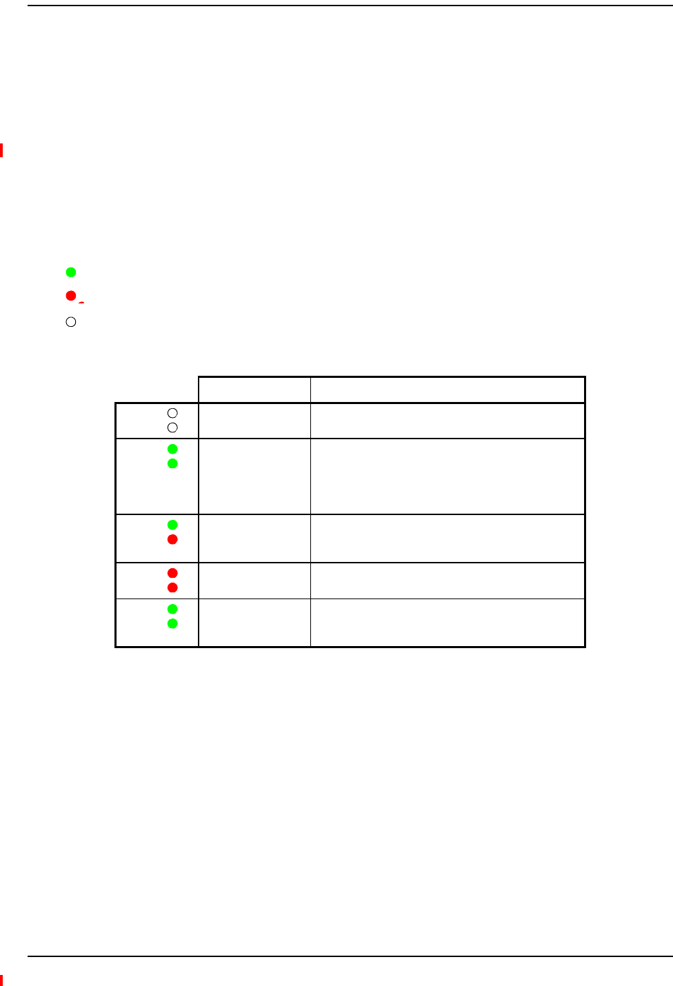
Remote Access Unit
Page 58 InterReach Fusion Wideband Installation, Operation, and Reference Manual
© 2013 TE Connectivity Ltd D-620616-0-20 Rev H • TECP-77-044 Issue 7 • May 2013
RAULEDINDICATORS
Uponpowerup,theRAUgoesthroughatwo‐secondtesttochecktheLEDlamps.Duringthistime,
theLEDsblinkgreen/greenred/red,lettingyouvisuallyverifythattheLEDlampsandthe
firmwarearefunctioningproperly.
NOTE: Referto“Maintenance,Troubleshooting,andTechnicalAssistance”onpage181for
troubleshootingusingtheLEDs.
StatusLEDs
TheRAUstatusLEDscanbeinoneofthestatesshowninTable5‐3.TheseLEDscanbe:
Steady green
Steady red
Off
Table 0-1 Remote Access Unit LED States
LED State Indicates
Off
Off
The RAU is not receiving DC power.
Green
Green
The RAU is powered and is not indicating a fault
condition. Communication with the Fusion Wideband
Hub is normal; however, the system test may need to
be performed or a warning condition may exist (use
AdminBrowser to determine this).
Green
Red
The RAU is indicating a fault or lockout condition, but
communication with the Fusion Wideband Hub is
normal.
Red
Red
The RAU is reporting a fault and is not able to
communicate with the Fusion Wideband Hub
Green (60-ppm)
Green (60-ppm)
The RAU is reporting a lockout condition, but
communication with the Fusion Wideband Hub is
normal.
LINK
ALARM
LINK
ALARM
LINK
ALARM
LINK
ALARM
LINK
ALARM

Faults and Warnings
InterReach Fusion Wideband Installation, Operation, and Reference Manual Page 59
D-620616-0-20 Rev H • TECP-77-044 Issue 7 • May 2013 © 2013 TE Connectivity Ltd.
FAULTSANDWARNINGS
BothfaultandwarningconditionsarereportedtotheFusionWidebandHubwheretheyare
stored.OnlyfaultsareindicatedbythefaceplateLEDs.
Formoreinformation,referto“AppendixC:Faults,Warnings,StatusTablesforFusion,Fusion
Wideband,FusionSingleStar”onpage209.

Remote Access Unit
Page 60 InterReach Fusion Wideband Installation, Operation, and Reference Manual
© 2013 TE Connectivity Ltd D-620616-0-20 Rev H • TECP-77-044 Issue 7 • May 2013
REMOTEACCESSUNITSPECIFICATIONS
NOTE: Forsystemperformance,itisimportantthatyouuseonlylowloss,solidcoppercenterconductor
CATVcablewithqualityFconnectorsthatusecaptivecenterpinconductors.Referto“Appendix
A:CablesandConnectors”onpage191formoreinformation.
Table39.RemoteAccessUnitSpecifications
Specification Description
Dimensions (H W D) 54 mm × 286 mm × 281 mm
(2.13 in. × 11.25 in. × 11.13 in.)
Weight < 2.1 kg (< 4.6 lb.)
Operating Temperature –25° to +45°C (–13° to +113°F)
Non-operating Temperature –25° to +85°C (–13° to +185°F)
Operating Humidity, non-condensing 5% to 95%
RF Connectors One Type-F, female (CATV - 75 ohms)
One Type-N, female* (coaxial 50 ohms)
LED Alarm and Status Indicators Unit Status (1 pair):
•Link
•Alarm
Maximum Heat Dissipation (W) 50 typical, 64 max (from the Hub)
MTBF 202,684 hours
*T
wo type N female connectors for FSN-W1-1921-1, FSN-W2-808519-1, FSN-W2-7070-1,
FSN-W2-7575-1, FSN-W3-2626-1, FSN-W4-702121-1-HP, FSN-W4-752121-1-HP,
FSN-W5-851921-1-HP, and FSN-2500-2-WMAX RAUs

InterReach Fusion Wideband Installation, Operation, and Reference Manual Page 61
D-620616-0-20 Rev H • TECP-77-044 Issue 7 • May 2013 ©2013 TE Connectivity Ltd.
DESIGNINGAFUSIONWIDEBANDSOLUTION
Overview ............................................................................................................................................................................... 62
DownlinkRSSIDesignGoal .................................................................................................................................................... 64
MaximumOutputPowerperCarrier...................................................................................................................................... 65
700/AWSRAU(FSN‐W2‐7021‐1) ..............................................................................................................................................65
700MHz(UpperC)MIMORAU(FSN‐W2‐7575‐1) ...................................................................................................................67
700MHz(LowerABC)MIMORAU(FSN‐W2‐7070‐1)...............................................................................................................67
700ABC/AWSHP/AWSHPRAU(FSN‐W4‐702121‐1‐HP).........................................................................................................68
700UC/AWSHP/AWSHPRAU(FSN‐W4‐752121‐1‐HP)...........................................................................................................69
800/850/1900RAU(FSN‐W2‐808519‐1) ..................................................................................................................................70
850/1900HP/AWSHPRAU(FSN‐W5‐851921‐1‐HP)................................................................................................................73
1900/AWSRAU(FSN‐W1‐1921‐1)............................................................................................................................................75
2100/1800RAU(FSN‐W1‐2118‐1)............................................................................................................................................77
2100HP/1800HPRAU(FSN‐W1‐2118‐1‐HP) ...........................................................................................................................78
2100HighPowerRAU(FSN‐W1‐21HP‐1) .................................................................................................................................79
2500/2500WiMAXRAU(FSN‐2500‐2‐WMAX).........................................................................................................................79
2600MHzMIMORAU(FSN‐W3‐2626‐1) .................................................................................................................................79
DesigningforCapacityGrowth.................................................................................................................................................80
SystemGain........................................................................................................................................................................... 81
EstimatingRFCoverage.......................................................................................................................................................... 82
Equation1 ................................................................................................................................................................................82
Equation2—PathLossEquation ..............................................................................................................................................83
RAUCoverageDistance ............................................................................................................................................................84
Equation3 ................................................................................................................................................................................84
Equation4—PathLossEquation ..............................................................................................................................................85
ExampleDesignEstimateforan1900MHzCDMAApplication ...............................................................................................87
LinkBudgetAnalysis .............................................................................................................................................................. 89
ElementsofaLinkBudgetforNarrowbandStandards ............................................................................................................89
NarrowbandLinkBudgetAnalysisforaMicrocellApplication ................................................................................................91
ElementsofaLinkBudgetforCDMAStandards ...................................................................................................................... 93
OtherCDMAIssues...................................................................................................................................................................95
CDMALinkBudgetAnalysisforaMicrocellApplication...........................................................................................................96
ConsiderationsforRe‐Radiation(Over‐the‐Air)Systems .........................................................................................................99
OpticalPowerBudget .......................................................................................................................................................... 100
ConnectingaMainHubtoaBaseStation............................................................................................................................. 101
UplinkAttenuation .................................................................................................................................................................102
RAUAttenuationandALC.......................................................................................................................................................102
UsingtheRAU10dBAttenuationSetting ......................................................................................................................103
UsingtheUplinkALCSetting ..........................................................................................................................................104
Topics Page

Designing a Fusion Wideband Solution
Page 62 InterReach Fusion Wideband Installation, Operation, and Reference Manual
© 2013 TE Connectivity Ltd D-620616-0-20 Rev H • TECP-77-044 Issue 7 • May 2013
OVERVIEW
DesigningaFusionWidebandsolutionisamatterofdeterminingcoverageandcapacityneeds.
Thisrequiresthefollowingsteps:
1Determinethewirelessserviceprovider’srequirements;referto“DownlinkRSSI
DesignGoal”onpage64.
Thefollowinginformationistypicallyprovidedbytheserviceprovider:
•Frequency(forexample,1900MHz)
•Band(forexample,“A‐F”bandinthePCSspectrum)
•Protocol(forexample,CDMA,GSM,1xRTT,GPRS,andsoon)
•Numberofsectorsandpeakcapacitypersector(translatestothenumberofRFcarriers
thatthesystemwillhavetotransmit)
•DownlinkRSSIdesigngoal(RSSI,receivedsignalstrengthatthewirelesshandset,for
example,–85dBm)
Thedesigngoalisalwaysastrongersignalthanthemobilephoneneeds.Itincludes
inherentfactorswhichaffectperformance.
•RFsource(basestationorbidirectionalamplifierorrepeater),typeofequipmentif
possible.
2DeterminethedownlinkpowerpercarrierfromtheRFsourcethroughtheDAS;refer
to“MaximumOutputPowerperCarrier”onpage65.
Themaximumpowerpercarrierisafunctionofmodulationtype,thenumberofRFcarriers,
signalqualityissues,regulatoryemissionsrequirements,andFusionWideband’sRF
performance.Powerpercarrierdecreasesasthenumberofcarriersincreases.
3DevelopanRFlinkbudget;referto“EstimatingRFCoverage”onpage82.
KnowingboththepowerpercarrierandRSSIdesigngoal,youcandevelopanRFdownlink
linkbudgetwhichestimatestheallowablepathlossfromanRAU’santennatothewireless
handset.
allowablepathloss=powerpercarrier+antennagain–designgoal
Satisfactoryperformancecanbeexpectedaslongaspathlossisbelowthislevel.

Overview
InterReach Fusion Wideband Installation, Operation, and Reference Manual Page 63
D-620616-0-20 Rev H • TECP-77-044 Issue 7 • May 2013 © 2013 TE Connectivity Ltd.
4Determinethein‐buildingenvironment;referto“EstimatingRFCoverage”onpage82.
•Determinewhichareasofthebuildingrequirecoverage(entirebuilding,publicareas,
parkinglevels,andsoon.)
•Obtainfloorplanstodeterminefloorspaceofbuildingandthewalllayoutoftheproposed
areastobecovered.Floorplansarealsousefulwhenyouareselectingantennalocations.
•Ifpossible,determinethebuilding’sconstructionmaterials(sheetrock,metal,concrete,
andsoon.)
•Determinethetypeofenvironment:
–Openlayout(forexample,aconventioncenter)
–Dense,closewalls(forexample,ahospital)
–Mixeduse(forexample,anofficebuildingwithhardwallofficesandcubicles)
5Determinetheappropriateestimatedpathlossslopethatcorrespondstothetypeof
buildinganditslayout,andestimatethecoveragedistanceforeachRAU;referto
“EstimatingRFCoverage”onpage82.
Usethepathlossslope(PLS),whichgivesavaluetotheRFpropagationcharacteristicswithin
thebuilding,toconverttheRFlinkbudgetintoanestimateofthecoveragedistanceper
antenna.ThishelpsestablishthequantitiesofFusionWidebandequipmentyouneed.The
actualpathlossslopethatcorrespondstothespecificRFenvironmentinsidethebuildingcan
alsobedeterminedempiricallybyperforminganRFsite‐surveyofthebuilding.Thisinvolves
transmittingacalibratedtoneforafixedantennaandmakingmeasurementswithamobile
antennathroughouttheareasurroundingthetransmitter.
6Determinetheitemsrequiredtoconnecttothebasestation;referto“Connectinga
MainHubtoaBaseStation”onpage101.
OnceyouknowthequantitiesofFusionWidebandequipmenttobeused,youcandetermine
theaccessories(combiners/dividers,surgesuppressors,repeaters,attenuators,circulators,
andsoon.)requiredtoconnectthesystemtothebasestation.
TheindividualelementsthatmustbeconsideredindesigningaFusionWidebandsolutionare
explainedinthefollowingsections.
NOTE: AccesstheTECustomerPortalforon‐linedimensioninganddesigntools;see“TECustomer
Portal”onpage3.

Designing a Fusion Wideband Solution
Page 64 InterReach Fusion Wideband Installation, Operation, and Reference Manual
© 2013 TE Connectivity Ltd D-620616-0-20 Rev H • TECP-77-044 Issue 7 • May 2013
DOWNLINKRSSIDESIGNGOAL
Wirelessserviceproviderstypicallyprovideaminimumdownlinksignallevelandanassociated
confidencefactorwhenspecifyingcoveragerequirements.Thesetwofiguresofmeritarea
functionofwirelesshandsetsensitivityandmarginsforfadingandbodyloss.Wirelesshandset
sensitivityistheweakestsignalthatthehandsetcanprocessreliablyandisacombinationofthe
thermalnoiseinthechannel,noisefigureofthehandsetreceiverfrontendandminimum
requiredSNR.Fademarginsformultipathfading(fastorsmall‐scale)andlog‐normalshadow
fading(sloworlarge‐scale)aredeterminedbythedesiredconfidencefactor,andotherfactors.
DownlinkRSSIdesigngoalcalculationsfortheGSMprotocolareshownbelowfora95%area
coverageconfidencefactor.
Downlinkdesigngoalsontheorderof–85dBmaretypicalforprotocols,suchasGSM.Wireless
serviceprovidersmaychooseahigherleveltoensurethatin‐buildingsignaldominatesany
macrosignalthatmaybeleakingintothebuilding.
Noise Power
10 Log (KT)+10 Log (200 KHz); K=1.38X10⁻²³, T=300 degrees Kelvin
-121 dBm
Wireless Handset Noise Figure 8 dB
Required SNR 9 dB
Multipath Fade Margin
95% Reliability for Rician K=6 dB
6 dB
Log-normal Fade Margin
95% Area/87% Edge Reliability for 35 dB PLS and 9 dB Sigma
10 dB
Body Attenuation + 3 dB
Downlink RSSI Design Goal (PDesignGoal)
Signal level received by wireless handset at edge of coverage area
-85 dBm

Maximum Output Power per Carrier
InterReach Fusion Wideband Installation, Operation, and Reference Manual Page 65
D-620616-0-20 Rev H • TECP-77-044 Issue 7 • May 2013 © 2013 TE Connectivity Ltd.
MAXIMUMOUTPUTPOWERPERCARRIER
ThefollowingtablesshowtherecommendedmaximumpowerpercarrieroutoftheRAU50Ohm
Type‐Nconnectorfordifferentfrequencies,protocols,andnumbersofcarriers.Thesemaximum
levelsaredictatedbyRFsignalqualityandregulatoryemissionsissues.Ingeneral,asthenumber
ofRFcarrierincreases,themaximumpowerpercarrierdecreases.Iftheselevelsareexceeded,
signalqualitywillbedegradedand/orregulatorrequirementswillbeviolated.Themaximum
inputpowertotheHubisdeterminedbysubtractingthesystemgainfromthemaximumoutput
poweroftheRAU.Systemgainissoftwareselectablefrom0dBto15dBin1dBsteps.
Additionally,boththeuplinkanddownlinkgainofeachRAUcanbeattenuated0or10dB.
WhenconnectingaHubtoabasestationorrepeater,attenuationonthedownlinkistypically
requiredtoavoidexceedingFusionWideband’smaximumoutputpowerrecommendations.
CAUTION! ExceedingthemaximuminputpowermaycausepermanentdamagetotheHub.Donotexceed
themaximumcompositeinputpowerof1W(+30dBm)totheHubatanytime.
NOTE: ThesespecificationsarefordownlinkpowerattheRAUoutput(excludingantenna).
700/AWSRAU(FSN‐W2‐7021‐1)
Table40.700MHz(LowerA,B,C)PowerperCarrier
Number of
Carriers
Power per Carrier (dBm)
WCDMA LTE
114.0 14.0
211.0 11.0
39.0 9.0
48.0 8.0
57.0 7.0
Note: Operation at or above these
output power levels may prevent
Fusion Wideband from meeting
RF performance specifications
or FCC Part 15 and EN55022
emissions requirements.

Designing a Fusion Wideband Solution
Page 66 InterReach Fusion Wideband Installation, Operation, and Reference Manual
© 2013 TE Connectivity Ltd D-620616-0-20 Rev H • TECP-77-044 Issue 7 • May 2013
Table41.700MHz(UpperC)PowerperCarrier
Number of Carriers
Power per Carrier (dBm)
LTE
114.0
211.0
39.0
48.0
57.0
Note: Operation at or above these output power
levels may prevent Fusion Wideband from
meeting RF performance specifications or
FCC Part 15 and EN55022 emissions
requirements.
Table42.AWSPowerperCarrier
Number of
Carriers
Power per Carrier (dBm)
WCDMA LTE
118.0 18.0
215.0 15.0
313.0 13.0
412.0 12.0
511.0 11.0
Note: Operation at or above these output power
levels may prevent Fusion Wideband from
meeting RF performance specifications or
FCC Part 15 and EN55022 emissions
requirements.

Maximum Output Power per Carrier
InterReach Fusion Wideband Installation, Operation, and Reference Manual Page 67
D-620616-0-20 Rev H • TECP-77-044 Issue 7 • May 2013 © 2013 TE Connectivity Ltd.
700MHz(UpperC)MIMORAU(FSN‐W2‐7575‐1)
700MHz(LowerABC)MIMORAU(FSN‐W2‐7070‐1)
Table43.700MHz(UpperC)PowerperCarrier
Number of Carriers
Power per Carrier (dBm)
LTE
118.0
215.0
313.0
412.0
511.0
Note: Operation at or above these output power levels
may prevent Fusion Wideband from meeting RF
performance specifications or FCC Part 15 and
EN55022 emissions requirements.
Table44.700MHz(LowerABC)PowerperCarrier
Number of
Carriers
Power per Carrier (dBm)
WCDMA LTE
118.0 18.0
215.0 15.0
313.0 13.0
412.0 12.0
511.0 11.0
Note: Operation at or above these output power
levels may prevent Fusion Wideband from
meeting RF performance specifications or
FCC Part 15 and EN55022 emissions
requirements.

Designing a Fusion Wideband Solution
Page 68 InterReach Fusion Wideband Installation, Operation, and Reference Manual
© 2013 TE Connectivity Ltd D-620616-0-20 Rev H • TECP-77-044 Issue 7 • May 2013
700ABC/AWSHP/AWSHPRAU(FSN‐W4‐702121‐1‐HP)
Table45.700MHz(LowerA,B,C)PowerperCarrier
Number of Carriers
Power per Carrier (dBm)
LTE
118.0
215.0
313.0
412.0
511.0
Note: Operation at or above these output power
levels may prevent Fusion Wideband from
meeting RF performance specifications or
FCC Part 15 and EN55022 emissions
requirements.
Table46.AWSPowerperCarrier
Number of
Carriers
Power per Carrier (dBm)
WCDMA LTE
123.0 23.0
220.0 20.0
318.0 18.0
417.0 17.0
516.0 16.0
Note: Operation at or above these output power
levels may prevent Fusion Wideband from
meeting RF performance specifications or
FCC Part 15 and EN55022 emissions
requirements.

Maximum Output Power per Carrier
InterReach Fusion Wideband Installation, Operation, and Reference Manual Page 69
D-620616-0-20 Rev H • TECP-77-044 Issue 7 • May 2013 © 2013 TE Connectivity Ltd.
700UC/AWSHP/AWSHPRAU(FSN‐W4‐752121‐1‐HP)
Table47.700MHz(UpperC)PowerperCarrier
Number of Carriers
Power per Carrier (dBm)
LTE
118.0
215.0
313.0
412.0
511.0
Note: Operation at or above these output power
levels may prevent Fusion Wideband from
meeting RF performance specifications or
FCC Part 15 and EN55022 emissions
requirements.
Table48.AWSPowerperCarrier
Number of
Carriers
Power per Carrier (dBm)
WCDMA LTE
123.0 23.0
220.0 20.0
318.0 18.0
417.0 17.0
516.0 16.0
Note: Operation at or above these output power
levels may prevent Fusion Wideband from
meeting RF performance specifications or
FCC Part 15 and EN55022 emissions
requirements.

Designing a Fusion Wideband Solution
Page 70 InterReach Fusion Wideband Installation, Operation, and Reference Manual
© 2013 TE Connectivity Ltd D-620616-0-20 Rev H • TECP-77-044 Issue 7 • May 2013
800/850/1900RAU(FSN‐W2‐808519‐1)
Table49.800MHzPowerperCarrier
Number of
Carriers
Power per Carrier (dBm)
CDMA 2000 LTE iDEN Analog FM
APCO
25
CQPSK
APCO
25
C4FM
117.0 17.0 16.5 24.0 21.0 24.0
214.0 14.0 13.0 19.0 16.0 18.5
312.0 12.0 10.5 15.5 13.5 15.0
411.0 11.0 9.0 12.5 11.5 12.5
510.0 10.0 8.0 11.0 10.0 10.5
69.0 7.0 9.5 8.5 9.0
78.5 6.0 8.5 8.0 8.0
88.0 5.5 7.5 7.0 7.5
95.0 7.0 6.5 6.5
10 4.5 6.0 6.0 6.0
11 4.0
12 3.5
13 3.0
14 3.0
15 2.5
16 2.0
Note: Operation at or above these output power levels may prevent Fusion Wideband from meeting RF
performance specifications or FCC Part 15 and EN55022 emissions requirements.

Maximum Output Power per Carrier
InterReach Fusion Wideband Installation, Operation, and Reference Manual Page 71
D-620616-0-20 Rev H • TECP-77-044 Issue 7 • May 2013 © 2013 TE Connectivity Ltd.
Table50.850MHzPowerperCarrier
Number of
Carriers
Power per Carrier (dBm)
GSM EDGE CDMA 2000 WCDMA LTE
125.0 22.0 18.0 18.0 18.0
219.0 16.5 15.0 15.0 15.0
315.5 13.0 13.0 13.0 13.0
413.0 11.0 12.0 12.0 12.0
511.0 9.5 11.0 11.0 11.0
610.0 8.5 10.0
79.0 8.0 9.5
88.0 7.0 9.0
97.5 6.5
10 7.0 6.0
11 6.5 5.5
12 6.0 5.0
13 5.5 4.5
14 5.5 4.5
15 5.0 4.0
16 4.5 4.0
Note: Operation at or above these output power levels may prevent Fusion Wideband from
meeting RF performance specifications or FCC Part 15 and EN55022 emissions
requirements.

Designing a Fusion Wideband Solution
Page 72 InterReach Fusion Wideband Installation, Operation, and Reference Manual
© 2013 TE Connectivity Ltd D-620616-0-20 Rev H • TECP-77-044 Issue 7 • May 2013
Table51.1900MHzPowerperCarrier
Number of
Carriers
Power per Carrier (dBm)
GSM EDGE CDMA 2000 WCDMA LTE
126.0 23.0 18.0 18.0 18.0
220.0 17.5 15.0 15.0 15.0
316.5 14.0 13.0 13.0 13.0
414.0 12.0 12.0 12.0 12.0
512.0 10.5 11.0 11.0 11.0
611.0 9.5 10.0
710.0 9.0 9.5
89.0 8.0 9.0
98.5 7.5
10 8.0 7.0
11 7.5 6.5
12 7.0 6.0
13 6.5 5.5
14 6.5 5.5
15 6.0 5.0
16 5.5 5.0
Note: Operation at or above these output power levels may prevent Fusion
Wideband from meeting RF performance specifications or FCC Part 15 and
EN55022 emissions requirements.

Maximum Output Power per Carrier
InterReach Fusion Wideband Installation, Operation, and Reference Manual Page 73
D-620616-0-20 Rev H • TECP-77-044 Issue 7 • May 2013 © 2013 TE Connectivity Ltd.
850/1900HP/AWSHPRAU(FSN‐W5‐851921‐1‐HP)
Table52.850MHzPowerperCarrier
Number of
Carriers
Power per Carrier (dBm)
GSM EDGE CDMA 2000 WCDMA LTE
126.0 23.0 18.0 18.0 18.0
220.0 17.5 15.0 15.0 15.0
316.5 14.0 13.0 13.0 13.0
414.0 12.0 12.0 12.0 12.0
512.0 10.5 11.0 11.0 11.0
611.0 9.5 10.0
710.0 9.0 9.5
89.0 8.0 9.0
98.5 7.5
10 8.0 7.0
11 7.5 6.5
12 7.0 6.0
13 6.5 5.5
14 6.5 5.5
15 6.0 5.0
16 5.5 5.0
Note: Operation at or above these output power levels may prevent Fusion
Wideband from meeting RF performance specifications or FCC Part 15 and
EN55022 emissions requirements.

Designing a Fusion Wideband Solution
Page 74 InterReach Fusion Wideband Installation, Operation, and Reference Manual
© 2013 TE Connectivity Ltd D-620616-0-20 Rev H • TECP-77-044 Issue 7 • May 2013
Table53.1900MHzPowerperCarrier
Number of
Carriers
Power per Carrier (dBm)
GSM EDGE CDMA 2000 WCDMA LTE
126.0 26.0 23.0 23.0 23.0
223.0 22.5 20.0 20.0 20.0
321.0 19.0 18.0 18.0 18.0
419.0 17.0 17.0 17.0 17.0
517.0 15.5 16.0 16.0 16.0
616.0 14.5 15.0
715.0 14.0 14.5
814.0 13.0 14.0
913.5 12.5
10 13.0 12.0
11 12.5 11.5
12 12.0 11.0
13 11.5 11.0
14 11.5 10.5
15 11.0 10.0
16 10.5 10.0
Note: Operation at or above these output power levels may prevent Fusion
Wideband from meeting RF performance specifications or FCC Part 15 and
EN55022 emissions requirements.
Table54.AWSPowerperCarrier
Number of
Carriers
Power per Carrier (dBm)
WCDMA LTE
123.0 23.0
220.0 20.0
318.0 18.0
417.0 17.0
516.0 16.0
Note: Operation at or above these output power
levels may prevent Fusion Wideband from
meeting RF performance specifications or
FCC Part 15 and EN55022 emissions
requirements.

Maximum Output Power per Carrier
InterReach Fusion Wideband Installation, Operation, and Reference Manual Page 75
D-620616-0-20 Rev H • TECP-77-044 Issue 7 • May 2013 © 2013 TE Connectivity Ltd.
1900/AWSRAU(FSN‐W1‐1921‐1)
Table55.1900MHzPowerperCarrier
Number of
Carriers
Power per Carrier (dBm)
GSM EDGE CDMA 2000 WCDMA LTE
126.0 23.0 18.0 18.0 18.0
220.0 17.5 15.0 15.0 15.0
316.5 14.0 13.0 13.0 13.0
414.0 12.0 12.0 12.0 12.0
512.0 10.5 11.0 11.0 11.0
611.0 9.5 10.0
710.0 9.0 9.5
89.0 8.0 9.0
98.5 7.5
10 8.0 7.0
11 7.5 6.5
12 7.0 6.0
13 6.5 5.5
14 6.5 5.5
15 6.0 5.0
16 5.5 5.0
Note: Operation at or above these output power levels may prevent Fusion
Wideband from meeting RF performance specifications or FCC Part 15 and
EN55022 emissions requirements.

Designing a Fusion Wideband Solution
Page 76 InterReach Fusion Wideband Installation, Operation, and Reference Manual
© 2013 TE Connectivity Ltd D-620616-0-20 Rev H • TECP-77-044 Issue 7 • May 2013
Table56.AWSPowerperCarrier
Number of
Carriers
Power per Carrier (dBm)
GSM EDGE CDMA 2000 WCDMA LTE
126.0 23.0 18.0 18.0 18.0
220.0 17.5 15.0 15.0 15.0
316.5 14.0 13.0 13.0 13.0
414.0 12.0 12.0 12.0 12.0
512.0 10.5 11.0 11.0 11.0
611.0 9.5 10.0
710.0 9.0 9.5
89.0 8.0 9.0
98.5 7.5
10 8.0 7.0
11 7.5 6.5
12 7.0 6.0
13 6.5 5.5
14 6.5 5.5
15 6.0 5.0
16 5.5 5.0
Note: Operation at or above these output power levels may prevent Fusion
Wideband from meeting RF performance specifications or FCC Part 15 and
EN55022 emissions requirements.

Maximum Output Power per Carrier
InterReach Fusion Wideband Installation, Operation, and Reference Manual Page 77
D-620616-0-20 Rev H • TECP-77-044 Issue 7 • May 2013 © 2013 TE Connectivity Ltd.
2100/1800RAU(FSN‐W1‐2118‐1)
Table57.1800MHzPowerperCarrier
Number of
Carriers
Power per Carrier (dBm)
GSM EDGE LTE
116.5 16.5 15.0
214.5 14.5 12.0
312.5 12.5 10.0
411.5 11.5 9.0
510.5 10.5 8.0
69.5 9.5 7.0
79.0 9.0 6.5
88.5 8.0 6.0
98.0 7.5
10 7.5 7.0
11 7.0 6.5
12 6.5 6.0
13 6.5 6.0
14 6.0 5.5
15 5.5 5.0
16 5.5 5.0
20 4.5 4.0
30 2.5 2.0
Note: Operation at or above these output power levels may prevent
Fusion Wideband from meeting RF performance specifications
or FCC Part 15 and EN55022 emissions requirements.
Table58.2100MHzPowerperCarrier
Number of Carriers
Power per Carrier (dBm)
WCDMA LTE
115.0 15.0
212.0 12.0
310.0 10.0
49.0 9.0
58.0 8.0
67.0 7.0
76.5 6.5
86.0 6.0
Note: Measurements were taken with no baseband clipping.
Note: Operation at or above these output power levels may prevent
Fusion Wideband from meeting RF performance specifications
or FCC Part 15 and EN55022 emissions requirements.

Designing a Fusion Wideband Solution
Page 78 InterReach Fusion Wideband Installation, Operation, and Reference Manual
© 2013 TE Connectivity Ltd D-620616-0-20 Rev H • TECP-77-044 Issue 7 • May 2013
2100HP/1800HPRAU(FSN‐W1‐2118‐1‐HP)
Table59.1800MHzPowerperCarrier
Number of
Carriers
Power per Carrier (dBm)
GSM EDGE LTE
120.0 20.0 20.0
217.0 17.0 17.0
315.0 15.0 15.0
414.0 14.0 14.0
513.0 13.0 13.0
612.0 12.0 12.0
711.5 11.5 11.5
811.0 11.0 11.0
910.5 10.5
10 10.0 10.0
11 9.5 9.5
12 9.0 9.0
13 8.5 8.5
14 8.5 8.5
15 8.0 8.0
16 7.5 7.5
20 6.5 6.5
30 5.0 5.0
Note: Operation at or above these output power levels may prevent
Fusion Wideband from meeting RF performance specifications
or FCC Part 15 and EN55022 emissions requirements.
Table60.2100MHzPowerperCarrier
Number of Carriers
Power per Carrier (dBm)
WCDMA LTE
120.0 20.0
217.0 17.0
315.0 15.0
414.0 14.0
513.0 13.0
612.0 12.0
711.5 11.5
811.0 11.0
Note: Measurements were taken with no baseband clipping.
Note: Operation at or above these output power levels may prevent
Fusion Wideband from meeting RF performance specifications
or FCC Part 15 and EN55022 emissions requirements.

Maximum Output Power per Carrier
InterReach Fusion Wideband Installation, Operation, and Reference Manual Page 79
D-620616-0-20 Rev H • TECP-77-044 Issue 7 • May 2013 © 2013 TE Connectivity Ltd.
2100HighPowerRAU(FSN‐W1‐21HP‐1)
2500/2500WiMAXRAU(FSN‐2500‐2‐WMAX)
2600MHzMIMORAU(FSN‐W3‐2626‐1)
Table61.2100MHzPowerperCarrier
Number of Carriers Power per Carrier (dBm)
WCDMA
122.0
219.0
317.0
416.0
515.0
614.0
713.5
813.0
Note: Measurements were taken with no baseband clipping.
Note: Operation at or above these output power levels may prevent
Fusion Wideband from meeting RF performance specifications
or FCC Part 15 and EN55022 emissions requirements.
Table62.2500MHzWiMAXPowerperCarrier
Number of Carriers Power per Carrier (dBm)
WCDMA
120.0
Note: Measurements taken with no baseband clipping.
Note: Operation at or above these output power levels may prevent
Fusion Wideband from meeting RF performance specifications
or FCC Part 15 and EN55022 emissions requirements.
Table63.2600MHzPowerperCarrier
Number of Carriers
Power per Carrier (dBm)
WCDMA LTE
118.0 18.0
215.0 15.0
313.0 13.0
412.0 12.0
511.0 11.0
Note: Operation at or above these output power levels may prevent Fusion Wideband
from meeting RF performance specifications or FCC Part 15 and EN55022
emissions requirements.

Designing a Fusion Wideband Solution
Page 80 InterReach Fusion Wideband Installation, Operation, and Reference Manual
© 2013 TE Connectivity Ltd D-620616-0-20 Rev H • TECP-77-044 Issue 7 • May 2013
DesigningforCapacityGrowth
FusionWidebandsystemsaredeployedtoenhancein‐buildingcoverageand/ortooff‐load
capacityfromamacrocellsite.Inmanyinstances,subscriberusageincreaseswithtimeandthe
wirelessproviderrespondsbyincreasingtheloadontheinstalledFusionWidebandsystem.For
example,theinitialdeploymentmightonlyrequiretwoRFcarriers,butfourRFcarriersmaybe
neededinthefuturebasedoncapacitygrowthforecasts.Therearetwooptionsfordealingwith
thisscenario:
1DesigntheinitialcoveragewithamaximumpowerpercarrierforfourRFcarriers.Thiswill
likelyresultinadditionalRAUs.
2DesigntheinitialcoveragefortwoRFcarriers,butreserveRAUportsontheHubforfuture
use.Theseportscanbeusedtofillpotentialcoverageholesoncethepowerpercarrieris
loweredtoaccommodatethetwoadditionalcarriers.

System Gain
InterReach Fusion Wideband Installation, Operation, and Reference Manual Page 81
D-620616-0-20 Rev H • TECP-77-044 Issue 7 • May 2013 © 2013 TE Connectivity Ltd.
SYSTEMGAIN
ThesystemgainoftheFusionWidebanddefaultsto0dBorcanbesetupto15dBin1dB
increments.Inaddition,uplinkanddownlinkgainsofeachRAUcanbeindependentlyattenuated
by0or10dBusingAdminBrowser.
TherecommendedmaximumlengthsofCATVcableareasfollows:
•ForRG‐59cable130metersforCommScopePN2065V.
•ForRG‐6cable140metersforCommScopePN2279V.
•ForRG‐11cable235metersforCommScopePN2293K.
Ifthemaximumdistanceisnotrequired,thencopper‐cladoversteelcenter‐conductorcablemay
beusetoreducecablecosts.
IftheCATVcableislongerthantherecommendeddistancepercabletype,thegainofthesystem
willdecrease,asshowninTable6‐18.
Table64.SystemGain(Loss)RelativetoCATVCableLength
Cable
Type
Comm-Sc
ope Part
Number
Plenum
Rated
Solid Copper
Conductor
Copper Clad
Conductor
Zero-loss RF
Maximum
Length
(meters)
Distance
Where RF
is 10dB
Below Input
RF
(meters)
RG-59 2065V Yes X 130 180
2022V Yes X 100 100*
5572R No X 95 95*
5565 No X 130 180
RG-6 2279V Yes X 140 190
2275V Yes X 140 150*
5726 No X 140 140*
5765 No X 140 190
RG-11 2293K Yes X 235 320
2285K Yes X 235 300*
5913 No X 235 300*
* Exceeding the distance of copper-clad cable will result in the attached RAU becoming
non-functional. If the distance of a cable run is at its maximum and is of concern, TE recommends
the use of solid copper cable to ensure successful operation.
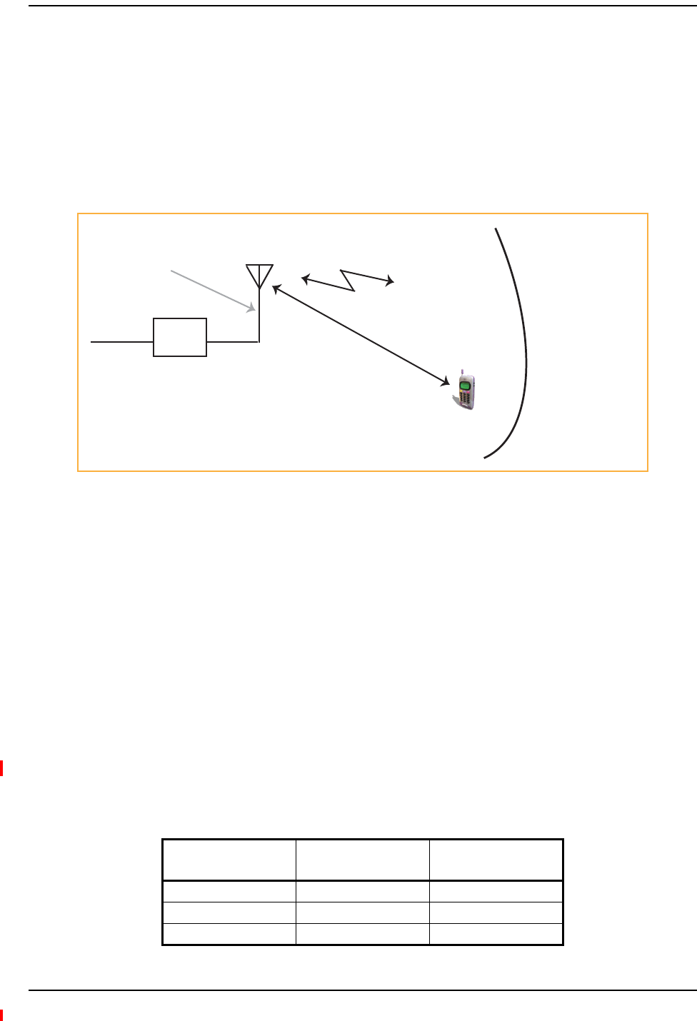
Designing a Fusion Wideband Solution
Page 82 InterReach Fusion Wideband Installation, Operation, and Reference Manual
© 2013 TE Connectivity Ltd D-620616-0-20 Rev H • TECP-77-044 Issue 7 • May 2013
ESTIMATINGRFCOVERAGE
Themaximumoutputpowerpercarrier(basedonthenumberandtypeofRFcarriersbeing
transmitted)andtheminimumacceptablereceivedpoweratthewirelessdevice(thatis,theRSSI
designgoal)essentiallyestablishtheRFdownlinkbudgetand,consequently,themaximum
allowablepathloss(APL)betweentheRAU’santennaandthewirelessdevice.Sincein‐building
systems,suchastheFusionWideband,aregenerallydownlink‐limited,thisapproachis
applicableinthemajorityofdeployments.
Figure19.Determining APL between the Antenna and the Wireless Device
Equation1
Equation1isasfollows:
APL=(P–Lcoax+G)–RSSI
where:
•APL=themaximumallowablepathlossindB
•P=thepowerpercarriertransmittedbytheRAUindBm
•Lcoax=thecoaxialcablelossbetweentheRAUandpassiveantennaindB
•G=thegainofthepassiveantennaindBi
CoaxialcableisusedtoconnecttheRAUtoanantenna.Table65listscoaxialcablelossforvarious
cablelengths.
Table65.CoaxialCableLosses(Lcoax)
Length of Cable
(.195 in. diameter) Loss at 850 MHz (dB) Loss at 1900 MHz (dB)
0.9 m (3 ft) 0.6 0.8
1.8 m (6 ft) 1.0 1.5
3.0 m (10 ft) 1.5 2.3
RAU
RSSI = power at the
wireless device
Distance = d
G = Antenna Gain
P = power per carrier
from the RAU
Lcoax = Coaxial cable loss

Estimating RF Coverage
InterReach Fusion Wideband Installation, Operation, and Reference Manual Page 83
D-620616-0-20 Rev H • TECP-77-044 Issue 7 • May 2013 © 2013 TE Connectivity Ltd.
Youcancalculatethedistance,d,correspondingtothemaximumallowablepathlossusing
equationsintroducedinthefollowingsections.
Equation2—PathLossEquation
In‐buildingpathlossobeysthedistancepowerlawinEquation2:
PL=20log10(40f/c)+10nlog10(d/d0)+Xs
where:
•PListhepathlossatadistance,d,fromtheantenna
•d=thedistanceexpressedinmeters
•d0=free‐spacepathlossdistanceinmeters
•f=theoperatingfrequencyinHertz.
•c=thespeedoflightinavacuum(3.0×10⁸m/sec).
•n=thepathlossexponentanddependsonthebuilding“clutter”andfrequencyofoperation
•Xs=anormalrandomvariablethatdependsonpartitionmaterialandgeometriesinsidethe
buildingandisaccountedforbythelog‐normalfademarginusedinthedownlinkRSSIdesign
goalcalculation
Asareference,Table66providesestimatesofsignallossforsomeRFbarriers1.
1 Rappaport,TheodoreS.WirelessCommunications,Principles,andPractice.PrenticeHallPTR,1996.
Table66.AverageSignalLossofCommonBuildingMaterials
Partition Type Loss (dB) Frequency (MHz)
Metal wall 26 815
Aluminum siding 20 815
Foil insulation 4 815
Cubicle walls 1.4 900
Concrete block wall 13 1300
Concrete floor 10 1300
Sheetrock 1 to 2 1300
Light machinery 3 1300
General machinery 7 1300
Heavy machinery 11 1300
Equipment racks 7 1300
Assembly line 6 1300
Ceiling duct 5 1300
Metal stairs 5 1300

Designing a Fusion Wideband Solution
Page 84 InterReach Fusion Wideband Installation, Operation, and Reference Manual
© 2013 TE Connectivity Ltd D-620616-0-20 Rev H • TECP-77-044 Issue 7 • May 2013
RAUCoverageDistance
Use“Equation1”onpage82and“Equation2—PathLossEquation”onpage83,respectively,to
estimatethedistancefromtheantennatowheretheRFsignaldecreasestotheminimum
acceptablelevelatthewirelessdevice.
Equation3
Equation2canbesimplifiedtoEquation3,withd0settoonemeterandpathlossslope(PLS)
definedas10n:
PL(d)=20log10(4/c)+PLS·log10(d)
Table67givesthevalueofthefirsttermofEquation3(thatis,(20log10(4f/c))forvarious
frequencybands.
Table68showsestimatedPLSforvariousenvironmentsthathavedifferent“clutter”(thatis,
objectsthatattenuatetheRFsignals,suchaswalls,partitions,stairwells,equipmentracks,andso
forth).
Table67.FrequencyBandsandtheValueoftheFirstTerminEquation3
Frequency Band (MHz) Mid-Band
Frequency
(MHz)
20log10(4/c)
Uplink Downlink
800 MHz SMR 806-824 851-869 838 30.9
850 MHz Cellular 824-849 869-894 859 31.1
1800 MHz DCS 1710-1785 1805-1880 1795 37.5
1900 MHz PCS 1850-1910 1930-1990 1920 38.1
2.1 GHz UMTS 1920–1980 2110–2170 2045 38.7
1.7/2.1 GHz AWS 1710-1755 2110-2155 2132.5* 39.0
2.5 GHz WiMAX 2496-2690 2496-2690 2595 40.7
* Due to the wide frequency spread between the Uplink and Downlink bands,
the mid-band frequency of the Downlink band was chosen for 1.7/2.1 GHz
AWS.
Table68.EstimatedPathLossSlopeforDifferentIn‐BuildingEnvironments
Environment Type Example PLS for
850/900 MHz
PLS for
1800/1900/
2100/2500 MHz
Open Environment
very few RF obstructions
Parking Garage, Convention Center 33.7 30.1
Moderately Open Environment
low-to-medium amount of RF obstructions
Warehouse, Airport, Manufacturing 35 32
Mildly Dense Environment
medium-to-high amount of RF obstructions
Retail, Office Space with approximately 80%
cubicles and 20% hard walled offices
36.1 33.1
Moderately Dense Environment
medium-to-high amount of RF obstructions
Office Space with approximately 50% cubicles and
50% hard walled offices
37.6 34.8
Dense Environment
large amount of RF obstructions
Hospital, Office Space with approximately 20%
cubicles and 80% hard walled offices
39.4 38.1

Estimating RF Coverage
InterReach Fusion Wideband Installation, Operation, and Reference Manual Page 85
D-620616-0-20 Rev H • TECP-77-044 Issue 7 • May 2013 © 2013 TE Connectivity Ltd.
Equation4—PathLossEquation
Bysettingthepathlosstothemaximumallowablelevel(PL=APL),Equation3canbeusedto
estimatethemaximumcoveragedistanceofanantennaconnectedtoanRAU,foragiven
frequencyandtypeofin‐buildingenvironment,whichisEquation4.
d=10^((APL‐20log10(4/c))/PLS)
Forreference,Table69throughTable75onpage87showthedistancecoveredbyanantennafor
variousin‐buildingenvironments,inwhichthefollowingassumptionsweremade:
•PathLossEquation4
•6dBmoutputpercarrierattheRAUoutput
•3dBiantennagain
•RSSIdesigngoalisequalto–85dBm,whichistypicalfornarrowbandprotocols,butnotfor
spread‐spectrumprotocols.
Table69.ApproximateRadiatedDistancefromAntennafor800MHzSMRApplications
Environment Type Distance from Antenna
Meters Feet
Open Environment 75 244
Moderately Open Environment 64 208
Mildly Dense Environment 56 184
Moderately Dense Environment 48 156
Dense Environment 40 131
Table70.ApproximateRadiatedDistancefromAntennafor850MHzCellularApplications
Environment Type Distance from Antenna
Meters Feet
Open Environment 73 241
Moderately Open Environment 63 205
Mildly Dense Environment 55 181
Moderately Dense Environment 47 154
Dense Environment 39 129

Designing a Fusion Wideband Solution
Page 86 InterReach Fusion Wideband Installation, Operation, and Reference Manual
© 2013 TE Connectivity Ltd D-620616-0-20 Rev H • TECP-77-044 Issue 7 • May 2013
Table71.ApproximateRadiatedDistancefromAntennafor1800MHzDCSApplications
Facility
Distance from Antenna
Meters Feet
Open Environment 75 246
Moderately Open Environment 58 191
Mildly Dense Environment 50 166
Moderately Dense Environment 42 137
Dense Environment 30 100
Table72.ApproximateRadiatedDistancefromAntennafor1900MHzPCSApplications
Facility
Distance from Antenna
Meters Feet
Open Environment 72 236
Moderately Open Environment 56 183
Mildly Dense Environment 49 160
Moderately Dense Environment 40 132
Dense Environment 29 96
Table73.ApproximateRadiatedDistancefromAntennafor2.1GHzUMTSApplications
Facility
Distance from Antenna
Meters Feet
Open Environment 69 226
Moderately Open Environment 54 176
Mildly Dense Environment 47 154
Moderately Dense Environment 39 128
Dense Environment 28 93
Table74.ApproximateRadiatedDistancefromAntennafor1.7/2.1GHzAWSApplications
Facility
Distance from Antenna
Meters Feet
Open Environment 67 220
Moderately Open Environment 52 172
Mildly Dense Environment 46 150
Moderately Dense Environment 38 125
Dense Environment 28 91

Estimating RF Coverage
InterReach Fusion Wideband Installation, Operation, and Reference Manual Page 87
D-620616-0-20 Rev H • TECP-77-044 Issue 7 • May 2013 © 2013 TE Connectivity Ltd.
ExampleDesignEstimateforan1900MHzCDMAApplication
1Designgoals:
•PCS(1920MHz=averageofthelowestuplinkandthehighestdownlinkfrequencyin
1900MHzPCSband)
•CDMAprovider
•8CDMAcarriersinthesystem
•–85dBmdesigngoal(to95%ofthebuilding);theminimumreceivedpoweratthe
wirelessdevice
•BasestationwithsimplexRFconnections.
2PowerPerCarrier:Thetablesin“MaximumOutputPowerperCarrier”onpage65provide
maximumpowerpercarrierinformation.The1900MHzCDMAtableindicatesthatFusion
Widebandcansupporteightcarrierswitharecommendedmaximumpowerpercarrierof6.5
dBm.Theinputpowershouldbesettothedesiredoutputpowerminusthesystemgain.
3Buildinginformation:
•16floorbuildingwith9,290sq.meters(100,000sq.ft.)perfloor;total148,640sq.meters
(1,600,000sq.ft.).
•Wallsaresheetrockconstruction,suspendedceilingtiles.
•Antennasusedareomni‐directional,ceilingmounted.
•Standardofficeenvironment,80%hardwallofficesand20%cubicles.
4LinkBudget:Inthisexample,adesigngoalof–85dBmisused.Suppose3dBi
omni‐directionalantennasareusedinthedesign.Then,themaximumRFpropagationloss
shouldbenomorethan94.5dB(6.5dBm+3dBi+85dBm)over95%oftheareabeing
covered.Itisimportanttonotethatadesigngoalsuchas–85dBmisusuallyderivedtakinginto
accountmultipathfadingandlog‐normalshadowingcharacteristics.Thus,thisdesigngoalwill
onlybemet“onaverage”over95%oftheareabeingcovered.Atanygivenpoint,afademay
bringthesignallevelunderneaththedesigngoal.
Notethatthismethodofcalculatingalinkbudgetisonlyforthedownlinkpath.For
informationtocalculatelinkbudgetsforboththedownlinkanduplinkpaths,referto“Link
BudgetAnalysis”onpage89.
Table75.ApproximateRadiatedDistancefromAntennafor2.5GHzWiMAXApplications
Facility
Distance from Antenna
Meters Feet
Open Environment 59 194
Moderately Open Environment 47 152
Mildly Dense Environment 41 134
Moderately Dense Environment 35 112
Dense Environment 25 83

Designing a Fusion Wideband Solution
Page 88 InterReach Fusion Wideband Installation, Operation, and Reference Manual
© 2013 TE Connectivity Ltd D-620616-0-20 Rev H • TECP-77-044 Issue 7 • May 2013
5PathLossSlope:Foraroughestimate,Table68onpage84showsthatabuildingwith80%
hardwallofficesand20%cubicles,at1920MHz,hasanapproximatepathlossslope(PLS)of
38.1.GiventheRFlinkbudgetof94.5dB,thedistanceofcoveragefromeachRAUwillbe30.2
meters(99ft).Thiscorrespondstoacoverageareaof2,868sq.meters(30,854sq.ft.)per
RAU(referto“Equation2—PathLossEquation”onpage83fordetailsonpathloss
estimation).Forthiscaseweassumedacircularradiationpattern,thoughtheactualarea
covereddependsuponthepatternoftheantennaandtheobstructionsinthefacility.
6EquipmentRequired:Sinceyouknowthebuildingsize,youcannowestimatetheFusion
Widebandequipmentquantitiesneeded.BeforeyoutestanyRFlevelsinthebuilding,youcan
estimatethatfourantennasperlevelwillbeneeded.Thisassumesnopropagationbetween
floors.Ifthereispropagation,youmaynotneedantennasoneveryfloor.
•4antennasperfloor×16floors=64RAUs
•64RAUs÷8=8ExpansionHubs,asthereisamaximumof8RAUsperExpansionHub
•8ExpansionHubs÷4=2MainHubs,asthereisamaximumof4ExpansionHubsperMain
Hub
CheckthatthefiberandCATVcabledistancesareasrecommended.Ifthedistancesdiffer,use
thetablesinSection6.4,“SystemGain,”onpage6‐16todeterminesystemgainsorlosses.The
pathlossmayneedtoberecalculatedtoassureadequatesignallevelsintherequired
coveragedistance.
Theaboveestimatesassumethatallcablelengthrequirementsaremet.IfExpansionHubs
cannotbeplacedsothattheRAUsarewithinthedistancerequirement,additionalExpansion
HubsmayneedtobeplacedclosertotherequiredRAUslocations.
AnRFSiteSurveyandBuildingEvaluationisrequiredtoaccuratelyestablishtheFusion
Widebandequipmentquantitiesrequiredforthebuilding.ThesitesurveymeasurestheRF
losseswithinthebuildingtodeterminetheactualPLS,usedinthefinalpathlossformulato
determinetheactualrequirementsoftheFusionWidebandsystem.

Link Budget Analysis
InterReach Fusion Wideband Installation, Operation, and Reference Manual Page 89
D-620616-0-20 Rev H • TECP-77-044 Issue 7 • May 2013 © 2013 TE Connectivity Ltd.
LINKBUDGETANALYSIS
AlinkbudgetisamethodicalwaytoaccountforthegainsandlossesinanRFsystemsothatthe
qualityofcoveragecanbepredicted.Theendresultcanoftenbestatedasa“designgoal”inwhich
thecoverageisdeterminedbythemaximumdistancefromeachRAUbeforethesignalstrength
fallsbeneaththatgoal.
OnekeyfeatureofthelinkbudgetisthemaximumpowerpercarrierexplainedinSection6.3.
Whilethemaximumpowerpercarrierisimportantasfarasemissionsandsignalquality
requirementsareconcerned,itiscriticalthatthemaximumsignalintotheMainHubneverexceed
1W(+30dBm).CompositepowerlevelsabovethislimitwillcausedamagetotheMainHub.
CAUTION! Exceedingthemaximuminputpowerof1W(+30dBm)couldcausepermanentdamagetothe
MainHub.
NOTE: VisittheTEcustomerportalfortheon‐lineLinkBudgetTool;see“TECustomerPortal”onpage3.
ElementsofaLinkBudgetforNarrowbandStandards
Thelinkbudgetrepresentsatypicalcalculationthatmightbeusedtodeterminehowmuchpath
losscanbeaffordedinaFusionWidebanddesign.Thislinkbudgetanalyzesboththedownlink
anduplinkpaths.Formostconfigurations,thedownlinkrequireslowerpathlossandistherefore
thelimitingfactorinthesystemdesign.Itisforthisreasonthatapredetermined“designgoal”for
thedownlinkissufficienttopredictcoveragedistance.
Thelinkbudgetisorganizedinasimplemanner:thetransmittedpoweriscalculated,theairlink
lossesduetofadingandbodylossaresummed,andthereceiversensitivity(minimumlevela
signalcanbereceivedforacceptablecallquality)iscalculated.Themaximumallowablepathloss
(indB)isthedifferencebetweenthetransmittedpower,lesstheairlinklosses,andthereceiver
sensitivity.Fromthepathloss,themaximumcoveragedistancecanbeestimatedusingthepath
lossformulapresentedinSection6.5.1.
Table76onpage90provideslinkbudgetconsiderationsfornarrowbandsystems.

Designing a Fusion Wideband Solution
Page 90 InterReach Fusion Wideband Installation, Operation, and Reference Manual
© 2013 TE Connectivity Ltd D-620616-0-20 Rev H • TECP-77-044 Issue 7 • May 2013
Table76.LinkBudgetConsiderationsforNarrowbandSystems
Consideration Description
BTS Transmit Power The power per carrier transmitted from the base station output
Attenuation between
BTS and Fusion
Wideband
This includes all losses: cable, attenuator, splitter/combiner, and so forth.
On the downlink, attenuation must be chosen so that the maximum power per carrier going into the Main
Hub does not exceed the levels given in “Maximum Output Power per Carrier” on page 65.
On the uplink, attenuation is chosen to keep the maximum uplink signal and noise level low enough to
prevent base station alarms but small enough not to cause degradation in the system sensitivity.
If the Fusion Wideband noise figure minus the attenuation is at least 10 dB higher than the BTS noise
figure, the system noise figure is approximately that of Fusion Wideband alone. Refer to “Connecting a
Main Hub to a Base Station” on page 101 for ways to independently set the uplink and downlink
attenuations between the base station and Fusion Wideband.
Antenna Gain The radiated output power includes antenna gain. For example, if you use a 3 dBi antenna at the RAU that
is transmitting 0 dBm per carrier, the effective radiated power (relative to an isotropic radiator) is 3 dBm
per carrier.
BTS Noise Figure This is the effective noise floor of the base station input (usually base station sensitivity is this effective
noise floor plus a certain C/I ratio).
Fusion Wideband Noise
Figure
This is Fusion Wideband’s uplink noise figure, which varies depending on the number of Expansion Hubs
and RAUs, and the frequency band. Fusion Wideband’s uplink noise figure is specified for a 1-1-8
configuration. Thus, the noise figure for a Fusion Wideband system (or multiple systems whose uplink
ports are power combined) is NF(1-1-8) + 10*log(# of Expansion Hubs). This represents an upper-bound
because the noise figure is lower if any of the Expansion Hub’s RAU ports are not used.
Thermal Noise This is the noise level in the signal bandwidth (BW).
Thermal noise power = –174 dBm/Hz + 10Log(BW).
Required C/I ratio For each wireless standard, a certain C/I (carrier to interference) ratio is needed to obtain acceptable
demodulation performance. For narrowband systems, (TDMA, GSM, EDGE, iDEN, AMPS) this level
varies from about 9 dB to 20 dB.
Mobile Transmit Power The maximum power the mobile can transmit (power transmitted at highest power level setting).
Multipath Fade
Margin
This margin allows for a certain level of fading due to multipath interference. Inside buildings there is
often one or more fairly strong signals and many weaker signals arriving from reflections and diffraction.
Signals arriving from multiple paths add constructively or destructively. This margin accounts for the
possibility of destructive multipath interference. In RF site surveys the effects of multipath fading are
typically not accounted for because such fading is averaged out over power level samples taken over
many locations.
Log-normal Fade
Margin
This margin adds an allowance for RF shadowing due to objects obstructing the direct path between the
mobile equipment and the RAU. In RF site surveys, the effects of shadowing are partially accounted for
since it is characterized by relatively slow changes in power level.
Body Loss This accounts for RF attenuation caused by the user’s head and body.
Minimum Received
Signal Level
This is also referred to as the “design goal”. The link budget says that you can achieve adequate coverage
if the signal level is, on average, above this level over 95% of the area covered, for example.
Protocol Signal
Bandwidth
Thermal Noise
TDMA 30 kHz –129 dBm
GSM 200 kHz –121 dBm
iDEN 25 kHz –130 dBm

Link Budget Analysis
InterReach Fusion Wideband Installation, Operation, and Reference Manual Page 91
D-620616-0-20 Rev H • TECP-77-044 Issue 7 • May 2013 © 2013 TE Connectivity Ltd.
NarrowbandLinkBudgetAnalysisforaMicrocellApplication
•c=a+b
•f=c+d+e
•j=g+h+i
•n=k+l+m
•k:inthisexample,krepresentsthethermalnoiseforaTDMAsignal,whichhasabandwidth
of30kHz
•p=f–j–n
Table77.NarrowbandLinkBudgetAnalysis:Downlink
Line Downlink
Transmitter
a. BTS transmit power per carrier (dBm) 33
b. Attenuation between BTS and Fusion Wideband (dB) –23
c. Power into Fusion Wideband (dBm) 10
d. Fusion Wideband gain (dB) 0
e. Antenna gain (dBi) 3
f. Radiated power per carrier (dBm) 13
Airlink
g. Multipath fade margin (dB) 6
h. Log-normal fade margin with 9 dB std. deviation, 95% area
coverage, 87% edge coverage
10
i. Body loss (dB) 3
j. Airlink losses (not including facility path loss) 19
Receiver
k. Thermal noise (dBm/30 kHz) –129
l. Mobile noise figure (dB) 7
m. Required C/I ratio (dB) 17
n. Minimum received signal (dBm) –105
p. Maximum path loss (dB) +99

Designing a Fusion Wideband Solution
Page 92 InterReach Fusion Wideband Installation, Operation, and Reference Manual
© 2013 TE Connectivity Ltd D-620616-0-20 Rev H • TECP-77-044 Issue 7 • May 2013
•e:enterthenoisefigureandgainofeachsystemcomponent(a,b,c,andd)intothestandard
cascadednoisefigureformula
•i=f+e+g–h
•m=j+k+l
•p=n–m–i
Therefore,thesystemisdownlinklimitedbutthedownlinkanduplinkarealmostbalanced,
whichisadesirablecondition.
Table78.NarrowbandLinkBudgetAnalysis:Uplink
Line Uplink
Receiver
a. BTS noise figure (dB) 4
b. Attenuation between BTS and Fusion Wideband (dB) –10
c. Fusion Wideband gain (dB) 0
d. Fusion Wideband noise figure (dB) 1-4-32 22
e. System noise figure (dB) 22.6
f. Thermal noise (dBm/30 kHz) –129
g. Required C/I ratio (dB) 12
h. Antenna gain (dBi) 3
i. Receive sensitivity (dBm) –97.4
Airlink
j. Multipath fade margin (dB) 6
k. Log-normal fade margin with 9 dB std. deviation, 95% area coverage, 87% edge coverage 10
l. Body loss (dB) 3
m. Airlink losses (not including facility path loss) 19
Transmitter
n. Mobile transmit power (dBm) 28
p. Maximum path loss (dB) 106.4
Fsys = F1 + + + ....
F2 – 1
G1
F3 – 1
G1G2
where
F = 10
(See Rappaport, Theodore S. Wireless Communications, Principles, and Practice. Prentice Hall PTR, 1996.)
(Noise Figure/10)
G = 10(Gain/10)

Link Budget Analysis
InterReach Fusion Wideband Installation, Operation, and Reference Manual Page 93
D-620616-0-20 Rev H • TECP-77-044 Issue 7 • May 2013 © 2013 TE Connectivity Ltd.
ElementsofaLinkBudgetforCDMAStandards
ACDMAlinkbudgetisslightlymorecomplicatedbecauseyoumustconsiderthespreadspectrum
natureofCDMA.UnlikenarrowbandstandardssuchasTDMAandGSM,CDMAsignalsarespread
overarelativelywidefrequencyband.Uponreception,theCDMAsignalisde‐spread.Inthe
de‐spreadingprocessthepowerinthereceivedsignalbecomesconcentratedintoanarrowband,
whereasthenoiselevelremainsunchanged.Hence,thesignal‐to‐noiseratioofthede‐spread
signalishigherthanthatoftheCDMAsignalbeforede‐spreading.Thisincreaseiscalled
processinggain.ForIS‐95andJ‐STD‐008,theprocessinggainis21dBor19dBdependingonthe
userdatarate(9.6Kbpsforrateset1and14.4Kbpsforrateset2,respectively).Becauseofthe
processinggain,aCDMAsignal(comprisingoneWalshcodechannelwithinthecompositeCDMA
signal)canbereceivedatalowerlevelthanthatrequiredfornarrowbandsignals.Areasonable
levelis–95dBm,whichresultsinabout–85dBmcompositeasshownbelow.
AnimportantissuetokeepinmindisthatthedownlinkCDMAsignaliscomposedofmany
orthogonalchannels:pilot,paging,sync,andtraffic.Thecompositepowerlevelisthesumofthe
powersfromtheindividualchannels.Table79showsanexample.
Thistableassumesthatthereare15activetrafficchannelsoperatingwith50%voiceactivity(so
thatthetotalpoweraddsupto100%).Noticethatthepilotandsyncchannelstogethercontribute
about25%ofthepower.WhenmeasuringthepowerinaCDMAsignalyoumustbeawarethatif
onlythepilotandsyncchannelsareactive,thepowerlevelwillbeabout6to7dBlowerthanthe
maximumpowerlevelyoucanexpectwhenallvoicechannelsareactive.Theimplicationisthat
ifonlythepilotandsyncchannelsareactive,andthemaximumpowerpercarriertablesaysthat
youshouldnotexceed10dBmforaCDMAsignal,forexample,thenyoushouldsettheattenuation
betweenthebasestationandtheMainHubsothattheMainHubreceives3dBm(assuming0dB
systemgain).
AnadditionalconsiderationforCDMAsystemsisthattheuplinkanddownlinkpathsshouldbe
gainandnoisebalanced.Thisisrequiredforproperoperationofsoft‐handofftotheoutdoor
networkaswellaspreventingexcessinterferencethatiscausedbymobilesontheindoorsystem
transmittingatpowerlevelsthatarenotcoordinatedwiththeoutdoormobiles.Thisbalanceis
achievedifthepowerleveltransmittedbythemobilesunderclose‐looppowercontrolissimilar
tothepowerleveltransmittedunderopen‐looppowercontrol.
Theopen‐looppowercontrolequationisasfollows:
wherePTXisthemobile’stransmittedpowerandPRXisthepowerreceivedbythemobile.
Table79.DistributionofPowerwithinaCDMASignal
Channel Walsh Code Number Relative Power Level
Pilot 0 20% –7.0 dB
Sync 32 5% –13.3 dB
Primary Paging 1 19% –7.3 dB
Traffic 8–31, 33–63 9% (per traffic channel) –10.3 dB
forCellular,IS‐95: PTX+PRX=–73dBm
forPCS,J‐STD‐008: PTX+PRX=–76dBm

Designing a Fusion Wideband Solution
Page 94 InterReach Fusion Wideband Installation, Operation, and Reference Manual
© 2013 TE Connectivity Ltd D-620616-0-20 Rev H • TECP-77-044 Issue 7 • May 2013
Thepowerleveltransmittedunderclosed‐looppowercontrolisadjustedbythebasestationto
achieveacertainEb/N0(explainedinTable6‐34onpage6‐32).Thedifferencebetweenthese
powerlevels,P,canbeestimatedbycomparingthepowerradiatedfromtheRAU,Pdownink,tothe
minimumreceivedsignal,Puplink,attheRAU:
It’sagoodideatokeep–12dB<P<12dB.
Table80provideslinkbudgetconsiderationsforCDMAsystems.
forCellular: P=Pdownink+Puplink+73dBm
forPCS: P=Pdownink+Puplink+76dBm
Table80.AdditionalLinkBudgetConsiderationsforCDMA
Consideration Description
Multipath Fade
Margin
The multipath fade margin can be reduced (by at least 3 dB) by using different lengths of optical fiber (this is
called “delay diversity”). The delay over fiber is approximately 5µS/km. If the difference in fiber lengths to
Expansion Hubs with overlapping coverage areas produces at least 1 chip (0.8µS) delay of one path relative
to the other, then the multipaths’ signals can be resolved and processed independently by the base station’s
rake receiver. A CDMA signal traveling through 163 meters of MMF cable is delayed by approximately one
chip.
Power per carrier,
downlink
This depends on how many channels are active. For example, the signal is about 7 dB lower if only the pilot,
sync, and paging channels are active compared to a fully-loaded CDMA signal. Furthermore, in the CDMA
forward link, voice channels are turned off when the user is not speaking. On average this is assumed to be
about 50% of the time. So, in the spreadsheet, both the power per Walsh code channel (representing how
much signal a mobile will receive on the Walsh code that it is de-spreading) and the total power are used.
The channel power is needed to determine the maximum path loss, and the total power is needed to
determine how hard the Fusion Wideband system is being driven.
The total power for a fully-loaded CDMA signal is given by (approximately):
total power = voice channel power + 13 dB + 10log10 (50%)
= voice channel power + 10 dB
Information Rate This is simply
10log10(9.6 Kbps) = 40 dB for rate set 1
10log10(14.4 Kbps) = 42 dB for rate set 2
Process Gain The process of de-spreading the desired signal boosts that signal relative to the noise and interference. This
gain needs to be included in the link budget. In the following formulas, PG = process gain:
PG = 10log10(1.25 MHz / 9.6 Kbps) = 21 dB rate set 1
PG = 10log10(1.25 MHz / 14.4 Kbps) = 19 dB rate set 2
Note that the process gain can also be expressed as 10log10 (CDMA bandwidth) minus the information rate.
Eb/No This is the energy-per-bit divided by the received noise and interference. It’s the CDMA equivalent of
signal-to-noise ratio (SNR). This figure depends on the mobile’s receiver and the multipath environment. For
example, the multipath delays inside a building are usually too small for a rake receiver in the mobile (or base
station) to resolve and coherently combine multipath components. However, if artificial delay can be
introduced by, for instance, using different lengths of cable, then the required Eb/No is lower and the multipath
fade margin in the link budget can be reduced in some cases.
If the receiver noise figure is NF (dB), then the receive sensitivity (dBm) is given by:
Psensitivity = NF + Eb/No + thermal noise in a 1.25 MHz band – PG
= NF + Eb/No – 113 (dBm/1.25 MHz) – PG

Link Budget Analysis
InterReach Fusion Wideband Installation, Operation, and Reference Manual Page 95
D-620616-0-20 Rev H • TECP-77-044 Issue 7 • May 2013 © 2013 TE Connectivity Ltd.
OtherCDMAIssues
OtherCDMAissuesareasfollows:
•Nevercombinemultiplesectors(morethanoneCDMAsignalatthesamefrequency)intoa
FusionWidebandsystem.ThecombinedCDMAsignalswillinterferewitheachother.
•Trytominimizeoverlapbetweenin‐buildingcoverageareasthatutilizedifferentsectors,as
wellasin‐buildingcoverageandoutdoorcoverageareas.Thisisimportantbecauseanyarea
inwhichmorethanonedominantpilotsignal(atthesamefrequency)ismeasuredbythe
mobilewillresultinsoft‐handoff.Soft‐handoffdecreasestheoverallnetworkcapacityby
allocatingmultiplechannelresourcestoasinglemobilephone.
Noise Rise On the uplink, the noise floor is determined not only by the Fusion Wideband system, but also by the number
of mobiles that are transmitting. This is because when the base station attempts to de-spread a particular
mobile’s signal, all other mobile signals appear to be noise. Because the noise floor rises as more mobiles
try to communicate with a base station, the more mobiles there are, the more power they have to transmit.
Hence, the noise floor rises rapidly:
noise rise = 10log10(1 / (1 – loading))
where loading is the number of users as a percentage of the theoretical maximum number of users.
Typically, a base station is set to limit the loading to 75%. This noise ratio must be included in the link budget
as a worst-case condition for uplink sensitivity. If there are less users than 75% of the maximum, then the
uplink coverage will be better than predicted.
Hand-off Gain CDMA supports soft hand-off, a process by which the mobile communicates simultaneously with more than
one base station or more than one sector of a base station. Soft hand-off provides improved receive
sensitivity because there are two or more receivers or transmitters involved. A line for hand-off gain is
included in the CDMA link budgets worksheet although the gain is set to 0 dB because the in-building system
will probably be designed to limit soft-handoff.
Table80.AdditionalLinkBudgetConsiderationsforCDMA(Cont.)
Consideration Description

Designing a Fusion Wideband Solution
Page 96 InterReach Fusion Wideband Installation, Operation, and Reference Manual
© 2013 TE Connectivity Ltd D-620616-0-20 Rev H • TECP-77-044 Issue 7 • May 2013
CDMALinkBudgetAnalysisforaMicrocellApplication
Table81.CDMALinkBudgetAnalysis:Downlink
Line Downlink
Transmitter
a. BTS transmit power per traffic channel (dBm) 30.0
b. Voice activity factor 50%
c. Composite power (dBm) 40.0
d. Attenuation between BTS and Fusion Wideband (dB) –24
e. Power per channel into Fusion Wideband (dBm) 9.0
f. Composite power into Fusion Wideband (dBm) 16.0
g. Fusion Wideband gain (dB) 0.0
h. Antenna gain (dBi) 3.0
i. Radiated power per channel (dBm) 12.0
j. Composite radiated power (dBm) 19.0
Airlink
k. Handoff gain (dB) 0.0
l. Multipath fade margin (dB) 6.0
m. Log-normal fade margin with 9 dB std. deviation, 95% area coverage, 87% edge coverage 10.0
n. Additional loss (dB) 0.0
o. Body loss (dB) 3.0
p. Airlink losses (not including facility path loss) 19.0
Receiver
q. Mobile noise figure (dB) 7.0
r. Thermal noise (dBm/Hz) –174.0
s. Receiver interference density (dBm/Hz) –167.0
t. Information ratio (dB/Hz) 41.6
u. Required Eb/(No+lo)7.0
v. Minimum received signal (dBm) –118.4
w. Maximum path loss (dB) +99.4

Link Budget Analysis
InterReach Fusion Wideband Installation, Operation, and Reference Manual Page 97
D-620616-0-20 Rev H • TECP-77-044 Issue 7 • May 2013 © 2013 TE Connectivity Ltd.
•bandc:seenotesinTable6‐34regardingpowerpercarrier,downlink
•e=a+d
•f=c+d
•i=e+g+h
•j=f+g+h
•p=–k+l+m+n+o
•s=q+r
•v=s+t+u
•w=j–p–v
•x=j(downlink)+m(uplink)+P
where
P=Ptx+Prx=–73dBforCellular
–76dBforPCS

Designing a Fusion Wideband Solution
Page 98 InterReach Fusion Wideband Installation, Operation, and Reference Manual
© 2013 TE Connectivity Ltd D-620616-0-20 Rev H • TECP-77-044 Issue 7 • May 2013
•e:enterthenoisefigureandgainofeachsystemcomponent(a,b,c,andd)intothestandard
cascadednoisefigureformula
•h=e+f+g
•m=h+i+j–k–l
•r=n+o+p+q
•t=s–r–m
Table82.CDMALinkBudgetAnalysis:Uplink
Line Uplink
Receiver
a. BTS noise figure (dB) 3.0
b. Attenuation between BTS and Fusion Wideband (dB) –30.0
c. Fusion Wideband gain (dB) 0.0
d. Fusion Wideband noise figure (dB) 22.0
e. System noise figure (dB) 33.3
f. Thermal noise (dBm/Hz) –174.0
g. Noise rise 75% loading (dB) 6.0
h. Receiver interference density (dBm/Hz) –134.6
i. Information rate (dB/Hz) 41.6
j. Required Eb/(No+lo)5.0
k. Handoff gain (dB) 0.0
l. Antenna gain (dBi) 3.0
m. Minimum received signal (dBm) –91.1
Airlink
n. Multipath fade margin (dB) 6.0
o. Log-normal fade margin with 9 dB std. deviation, 95% area coverage, 87% edge coverage 10.0
p. Additional loss (dB) 0.0
q. Body loss (dB) 3.0
r. Airlink losses (not including facility path loss) 19.0
Transmitter
s. Mobile transmit power (dBm) 28.0
t. Maximum path loss (dB) 100.1
Fsys = F1 + + + ....
F2 – 1
G1
F3 – 1
G1G2
where
F = 10
(See Rappaport, Theodore S. Wireless Communications, Principles, and Practice. Prentice Hall PTR, 1996.)
(Noise Figure/10)
G = 10(Gain/10)

Link Budget Analysis
InterReach Fusion Wideband Installation, Operation, and Reference Manual Page 99
D-620616-0-20 Rev H • TECP-77-044 Issue 7 • May 2013 © 2013 TE Connectivity Ltd.
ConsiderationsforRe‐Radiation(Over‐the‐Air)Systems
FusionWidebandcanbeusedtoextendthecoverageoftheoutdoornetworkbyconnectingtoa
roof‐topdonorantennapointedtowardanoutdoorbasestation.Additionalconsiderationsfor
suchanapplicationofFusionWidebandare:
•Sizingthegainandoutputpowerrequirementsforabi‐directionalamplifier(repeater).
•Ensuringthatnoiseradiatedontheuplinkfromthein‐buildingsystemdoesnotcausethe
outdoorbasestationtobecomedesensitizedtowirelesshandsetsintheoutdoornetwork.
•Filteringoutsignalsthatlieinadjacentfrequencybands.Forinstance,ifyouareproviding
coverageforCellularB‐bandoperationitmaybenecessarytofilterouttheA,A’andA”bands
whichmaycontainstrongsignalsfromotheroutdoorbasestations.
FurtherinformationontheseissuescanbefoundinTEapplicationnotesforre‐radiation
applications.

Designing a Fusion Wideband Solution
Page 100 InterReach Fusion Wideband Installation, Operation, and Reference Manual
© 2013 TE Connectivity Ltd D-620616-0-20 Rev H • TECP-77-044 Issue 7 • May 2013
OPTICALPOWERBUDGET
FusionWidebandusesSC/APCconnectors.Theconnectorlossesassociatedwithmatingtothese
connectorsisaccountedforinthedesignandshouldnotbeincludedaselementsoftheoptical
powerbudget.Thereasonisthatwhentheopticalpowerbudgetisdefined,measurementsare
takenwiththeseconnectorsinplace.
TheFusionWidebandopticalpowerbudgetforbothmulti‐modeandsingle‐modefiber
cableis3.0dB(optical).
Themaximumlossthroughthefibercannotexceed3dB(optical).Themaximumlengthsofthe
fibercableshouldnotexceed500m(1,640ft)formulti‐modeand6km(19,685ft)for
single‐mode.Boththeopticalbudgetandthemaximumcablelengthmustbetakeninto
considerationwhendesigningthesystem.
NOTE: ItiscriticaltosystemperformancethatonlySC/APCfiberconnectorsareusedthroughoutthe
fibernetwork,includingfiberdistributionpanels.

Connecting a Main Hub to a Base Station
InterReach Fusion Wideband Installation, Operation, and Reference Manual Page 101
D-620616-0-20 Rev H • TECP-77-044 Issue 7 • May 2013 © 2013 TE Connectivity Ltd.
CONNECTINGAMAINHUBTOABASESTATION
TheFusionWidebandsystemsupportsuptothreeRFsources:oneforBand1,oneforBand2and
oneforBand3.Thissectionexplainshoweachbandcanbeconnectedtoitsassociatedbase
station.
EachFusionMainHubbandhasseparatesystemgainparameters.Forexample,Band1canbeset
for+5dBofdownlinksystemgainwhileBand2canhave+15dBofdownlinksystemgain.Thus,
eachbandcanbeconfiguredasaseparatesystemtoallowforfullintegrationtoitsassociated
basestation.
WhenconnectingeachoftheFusionWidebandMainHubbandstoitsbasestation,thefollowing
equipmentmayberequired:
•circulators
•filterdiplexers
•directionalcouplers
•combiner/splitters
•attenuators
•coaxcables
•connectors.
Inaddition,usethefollowingconsiderationstoachieveoptimalperformance:
•Thedownlinkpowerfromthebasestationsmustbeattenuatedenoughsothatthepower
radiatedbytheRAUdoesnotexceedthemaximumpowerpercarrierlistedinSection6.3,
“MaximumOutputPowerperCarrier,”onpage6‐4.
•Theuplinkattenuationshouldbesmallenoughthatthesensitivityoftheoverallsystemis
limitedbyFusionWideband,notbytheattenuator.However,somebasestationstrigger
alarmsifthenoiseorsignallevelsaretoohigh.Inthiscasetheattenuationmustbelarge
enoughtopreventthisfromhappening.
CAUTION! TheUPLINKandDOWNLINKportscannothandleaDCpowerfeedfromaBTS.IfDCpoweris
present,aDCblockmustbeusedortheFusionWidebandMainHubmaybedamaged.
If,inanareacoveredbyFusionWideband,amobilephoneindicatesgoodsignalstrengthbut
consistentlyhasdifficultycompletingcalls,itispossiblethattheattenuationbetweenFusion
Widebandandthebasestationneedstobeadjusted.Inotherwords,itispossiblethatiftheuplink
isover‐attenuated,thedownlinkpowerwillprovidegoodcoverage,buttheuplinkcoverage
distancewillbesmall.
WhenthereisanexcessiveamountoflossbetweentheFusionWidebandMainHubuplinkandits
associatedband’sbasestation,theuplinksystemgaincanbeincreasedtoasmuchas15dBto
preventareductionintheoverallsystemsensitivity.

Designing a Fusion Wideband Solution
Page 102 InterReach Fusion Wideband Installation, Operation, and Reference Manual
© 2013 TE Connectivity Ltd D-620616-0-20 Rev H • TECP-77-044 Issue 7 • May 2013
UplinkAttenuation
TheattenuationbetweentheMainHub’suplinkportandtheassociatedband’sbasestation
reducesboththenoiselevelandthedesiredsignalsoutofFusionWideband.Settingthe
attenuationontheuplinkisatrade‐offbetweenkeepingthenoiseandmaximumsignallevels
transmittedfromFusionWidebandtothebasestationreceiverlowwhilenotreducingtheSNR
(signal‐to‐noiseratio)ofthepathfromtheRAUinputstothebasestationinputs.ThisSNRcannot
bebetterthantheSNRofFusionWidebandbyitself,althoughitcanbesignificantlyworse.
AgoodruleofthumbistosettheuplinkattenuationsuchthatthenoiseleveloutofFusion
Widebandiswithin10dBofthebasestation’ssensitivity.
RAUAttenuationandALC
TheRAUattenuationandALCaresetusingtheAdminBrowserEditUnitPropertiesscreen.
EmbeddedwithintheuplinkRFfront‐endofeachFusionWidebandRAUbandisanALCcircuit.
ThisALCcircuitprotectstheFusionWidebandsystemfromoverloadandexcessive
intermodulationproductsduetohigh‐poweredmobilesorothersignalsourcesthatarewithin
thesupportedfrequencybandandareincloseproximitytotheRAU.
EachindividualBand(1or2)ofaFusionWidebandRAUhasanuplinkALCcircuitthatoperates
asafeedbackloop.Apowerdetectormeasuresthelevelofeachband’suplinkRFinputandifthat
levelexceeds–30dBm,anRFattenuatorisactivated.Thelevelofattenuationisequaltothe
amountthattheinputexceeds–30dBm.Thefollowingsequencedescribestheoperationofthe
ALCcircuit,asillustratedinFigure6‐2.
1TheRFsignallevelintoeitherBandoftheRAUrisesabovetheactivationthreshold(–30
dBm),causingthatALClooptoenterintotheattackphase.
2Duringtheattackphase,theALCloopincreasestheattenuation(0to30dB)untilthedetector
readingisreducedtotheactivationthreshold.Thedurationofthisattackphaseiscalledthe
attacktime.
3Aftertheattacktime,theALCloopenterstheholdphaseandmaintainsafixedattenuationso
longasthehigh‐levelRFsignalispresent.
4TheRFsignalleveldropsbelowthereleasethreshold(–45dBm)andtheALCloopentersthe
releasephase.
5Duringthereleasephase,theALCloopholdstheattenuationforafixedperiodthenquickly
releasestheattenuation.
AnimportantfeatureoftheALCloopisthatinStep3,theattenuationismaintainedatafixedlevel
untilthesignaldropsbyasignificantamount.ThispreventstheALCloopfromtrackingvariations
intheRFsignalitselfanddistortingthewaveformmodulation.
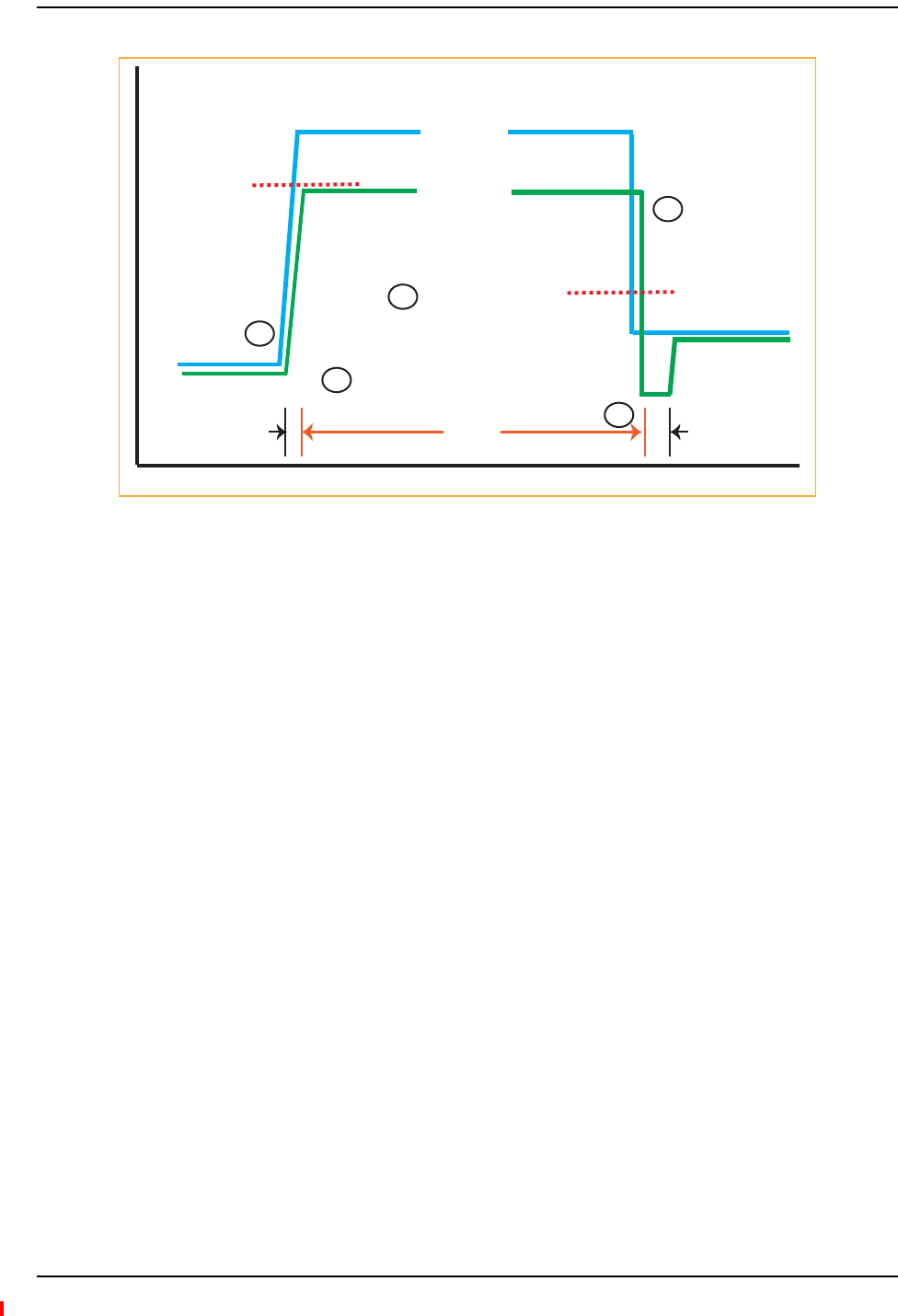
Connecting a Main Hub to a Base Station
InterReach Fusion Wideband Installation, Operation, and Reference Manual Page 103
D-620616-0-20 Rev H • TECP-77-044 Issue 7 • May 2013 © 2013 TE Connectivity Ltd.
Figure20.ALC Operation
UsingtheRAU10dBAttenuationSetting
EachRAUbandcan,independentlyoftheotherRAUsinasystem,haveitsuplinkordownlinkgain
attenuatedby0or10dBforeachRAUband(1,2or3).Thisisaccomplishedbyselectingthe
appropriateUPLINKand/orDOWNLINKattenuationforeachRAUbandintheEditUnit
PropertiesscreenofAdminBrowserfortheselectedRAU.
•DownlinkAttenuation:Thedownlinkattenuatorprovidesamechanismtoreducethesignal
strengthfromanRAUband.Forinstance,thiscouldbeforanRAUbandlocatedneara
windowinatallbuildingthatiscausingexcessiveleakagetothemacro‐network.Insucha
caseitisimportanttoattenuatethedownlinkonly.Theuplinkshouldnotbeattenuated.Ifthe
uplinkisattenuated,theuplinksensitivityisreducedandmobilephonesintheareaofthat
RAUbandwillhavetotransmitatahigherpower.Thiswouldincreaseinterferencetothe
outdoornetworkfromsuchmobiles.
•UplinkAttenuation:Theuplinkattenuatorattenuatesenvironmentalnoisepickedupbyan
RAUbandlocatedinanareawhereheavyelectricalmachineryisoperating.Insuch
environmentstheelectricalnoisecanbequitehighanditisusefultoreducetheamountof
suchnoisethatgetspropagatedthroughthedistributedantennasystem.Attenuatingthe
uplinkofanRAUbandlocatedinareasofhighelectricalnoisehelpspreservethesensitivity
oftherestofthesystem.
Attack
Phase
Release
Phase
Hold
Phase
Output Signal
Level
Activation
Level
-30 dBm
Input Signal
Level
Release
Level
-45 dBm
Time
1
1
5
2
3

Designing a Fusion Wideband Solution
Page 104 InterReach Fusion Wideband Installation, Operation, and Reference Manual
© 2013 TE Connectivity Ltd D-620616-0-20 Rev H • TECP-77-044 Issue 7 • May 2013
Theeffectofactivatingtheuplinkordownlinkattenuatorsistoreducethecoverageareaofthe
adjustedRAUband.Thecoverageradiuswillbereducedbyroughlyafactorof2.More
specifically,ifdisthecoveragedistancewithoutattenuationandd’isthecoverageradiuswith
theattenuation,then
wherePLSispathlossslope(dBm).
UsingtheUplinkALCSetting
Uplinkautomaticlevelcontrol(ULALC)circuitryforeachbandwithintheRAUprovides
automaticlevelcontrolonhigh‐powersignalsintheuplinkpath.Thisfunctionalityisrequiredto
preventRFsignalcompressioncausedbyasingleormultiplewirelessdevicesinveryclose
proximitytotheRAUband.Compressioncausessignaldegradationand,ultimately,droppedcalls
anddataerrors,andshouldbeprevented.TwosettingsareavailabletooptimizeULALC
performance:
•MultipleOperators:Usewhenmorethanoneoperatorand/orprotocolispresentinthe
FusionWidebandsystem’sbandfrequencyoradjacentfrequencybands.Thissettingismost
commonlyused.
•SingleOperatorandProtocol:Usewhenonlyoneoperatorandprotocolison‐the‐airwithin
theFusionWidebandsystem’sconfiguredandadjacentfrequencybands.Thissettingis
seldomused.

InterReach Fusion Wideband Installation, Operation, and Reference Manual Page 105
D-620616-0-20 Rev H • TECP-77-044 Issue 7 • May 2013 ©2013 TE Connectivity Ltd.
INSTALLINGFUSIONWIDEBAND
InstallationRequirements.................................................................................................................................................... 107
ComponentLocationRequirements.......................................................................................................................................107
CableandConnectorRequirements.......................................................................................................................................107
DistanceRequirements ..........................................................................................................................................................108
SafetyPrecautions ............................................................................................................................................................... 109
InstallationGuidelines............................................................................................................................................................109
GeneralSafetyPrecautions ....................................................................................................................................................109
FiberPortSafetyPrecautions .................................................................................................................................................110
PreparingforSystemInstallation ......................................................................................................................................... 111
Pre‐InstallationInspection .....................................................................................................................................................111
InstallationChecklist...............................................................................................................................................................111
ToolsandMaterialsRequired.................................................................................................................................................113
OptionalAccessories ..............................................................................................................................................................114
InstallingaFusionWidebandMainHub ............................................................................................................................... 115
InstallingaFusionWidebandMainHubinaRack..................................................................................................................115
InstallinganOptionalCableManagerintheRack..................................................................................................................116
InstallingaMainHubUsingthe12”Wall‐MountedRack(PN4712) .....................................................................................116
InstallingaFusionWidebandMainHubDirectlytotheWall.................................................................................................117
ConnectingtheFiberCablestotheMainHub .......................................................................................................................118
PreparingtheFiberCables .............................................................................................................................................118
CleaningtheFiberPorts .................................................................................................................................................118
UsingCompressedAir.............................................................................................................................................118
UsingIsopropylAlcohol ..........................................................................................................................................118
CleaningtheFiberEnds ..................................................................................................................................................119
TestingtheFiberCables .................................................................................................................................................119
ConnectingtheFiberCables...........................................................................................................................................119
Ifthefiberjumperislabeledwith1or2...................................................................................................................119
IftheFiberJumperisColor‐Coded .........................................................................................................................120
MakingPowerConnections....................................................................................................................................................120
ACPoweredMainHub ...................................................................................................................................................120
DCPoweredMainHubandExpansionHub....................................................................................................................120
OptionalConnectiontoDCPowerSource..............................................................................................................................124
PoweringontheMainHub....................................................................................................................................................126
InstallingExpansionHubs .................................................................................................................................................... 127
InstallinganExpansionHubinaRack ....................................................................................................................................127
InstallinganExpansionHubUsingthe12”Wall‐MountedRack ............................................................................................127
InstallinganExpansionHubDirectlytotheWall ...................................................................................................................128
InstallinganOptionalCableManagerintheRack..................................................................................................................129
PoweringontheExpansionHub ............................................................................................................................................129
ConnectingtheFiberCablestotheExpansionHub ...............................................................................................................130
PreparingtheFiberCables .............................................................................................................................................130
ConnectingtheFiberCables...........................................................................................................................................130
IftheFiberJumperIsLabeledwith1or2.................................................................................................................130
IftheFiberJumperIsColor‐Coded .........................................................................................................................131
Connectingthe75OhmCATVCables.....................................................................................................................................131
TroubleshootingExpansionHubLEDsDuringInstallation .....................................................................................................132
Topics Page