ADC Telecommunications F0674-011 Tri-Band Remote Antenna Unit User Manual 77044p7
ADC Telecommunications Inc. Tri-Band Remote Antenna Unit 77044p7
Contents
- 1. Users Manual Part I
- 2. Users Manual Part II
Users Manual Part II

Installing Fusion Wideband
Page 106 InterReach Fusion Wideband Installation, Operation, and Reference Manual
© 2013 TE Connectivity Ltd D-620616-0-20 Rev H • TECP-77-044 Issue 7 • May 2013
InstallingRAUs..................................................................................................................................................................... 133
InstallingRAUs........................................................................................................................................................................133
InstallingPassiveAntennas ....................................................................................................................................................133
Location ..........................................................................................................................................................................133
800/850MHzIsolationRequirements ........................................................................................................................... 134
800MHziDENDownlinkand850MHzCellularUplink ..................................................................................................135
850MHzCellularDownlinkand900MHziDENUplink ..................................................................................................135
ConnectingtheAntennatotheRAU ......................................................................................................................................135
ConnectingtheCATVCable....................................................................................................................................................136
TroubleshootingUsingRAULEDsDuringInstallation ............................................................................................................137
ConfiguringtheFusionWidebandSystem............................................................................................................................ 138
ConnectingthePCtotheMainHubtoRunAdminBrowser ..................................................................................................138
ProgrammingtheMainHubUsingAdminBrowser ................................................................................................................139
UsingAdminBrowser..............................................................................................................................................................140
SplicingFiberOpticCable..................................................................................................................................................... 145
FusionWidebandSplicingofFiberandPigtail .......................................................................................................................145
OptionA:FusionWidebandSplicetheFiber‐OpticCabletotheSC/APCPigtail............................................................145
OptionB:FusionWidebandSplicetheFiber‐OpticCabletotheSC/APCPigtail ............................................................146
InterfacingtheFusionWidebandMainHubtoanRFSource ................................................................................................ 147
ConnectingaSingleFusionWidebandMainHubtoanRFSource ........................................................................................147
ConnectingaFusionWidebandMainHubtoanIn‐BuildingBTS...........................................................................................147
ConnectingaSimplexBaseStationtoaFusionWidebandMainHubRFBand..............................................................148
ConnectingaDuplexBaseStationtoaFusionWidebandMainHub .............................................................................149
ConnectingaFusionWidebandMainHubRFBandtoMultipleBTSs....................................................................................150
ConnectingaFusionWidebandMainHubtoaRoof‐TopAntenna .......................................................................................151
ConnectingaFusionWidebandMainHubtoFlexwaveFocus...............................................................................................152
ConnectingMultipleFusionWidebandMainHubstoanRFSource......................................................................................152
ConnectingMultipleFusionWidebandMainHubstoaSimplexRepeaterorBTS ........................................................152
ConnectingMultipleFusionWidebandMainHubstoaDuplexRepeaterorBTS..........................................................154
ConnectingContactAlarmstoaFusionWidebandSystem ................................................................................................... 156
AlarmSource ..........................................................................................................................................................................157
UsingFlexWaveFocustoMonitorFusionWideband.....................................................................................................157
UsingaBaseStationtoMonitorFusionWideband........................................................................................................158
UsingaBaseStationandAdminBrowsertoMonitorFusionWideband........................................................................159
AlarmSense............................................................................................................................................................................160
AlarmCables...........................................................................................................................................................................161
AlarmMonitoringConnectivityOptions............................................................................................................................... 162
DirectConnection...................................................................................................................................................................162
ModemConnection................................................................................................................................................................162
SettingUpFusionWidebandModem(USRModem)UsingAdminBrowser ..................................................................163
SettingUpaPCModemUsingWindows........................................................................................................................ 164
100BASE‐TPortExpanderConnection .................................................................................................................................. 169
POTSLineSharingSwitchConnection....................................................................................................................................170
EthernetRFModem ...............................................................................................................................................................171
EthernetLANConnection.......................................................................................................................................................172
SNMPInterface ......................................................................................................................................................................172

Installation Requirements
InterReach Fusion Wideband Installation, Operation, and Reference Manual Page 107
D-620616-0-20 Rev H • TECP-77-044 Issue 7 • May 2013 © 2013 TE Connectivity Ltd.
INSTALLATIONREQUIREMENTS
Beforeandduringinstallation,keepinmindthesesourcesofpotentialproblems:
•Faultycabling/connector
•Dirtyconnectorsandports
•MalfunctionofoneormoreFusionWidebandcomponents
•Antenna,basestation,orrepeaterproblem
•ExternalRFinterface
•Trippedcircuitbreaker
•Equipmentisnotgrounded
•UsingacrossoverEthernetcablethatdoesnotsupportfullhardwarehandshakingwhen
usingAdminBrowser
NOTE: Faultycablingisthecauseofavastmajorityofproblems.AllCATVcableshouldbetestedto
TIA‐570‐Bspecifications.
ComponentLocationRequirements
FusionWidebandcomponentsareintendedtobeinstalledinindoorlocationsonly.
Ifoutdoorinstallationisdesired,suchasaparkinggarage,theFusionWidebandcomponents
mustbeinstalledintheappropriateenvironmentalenclosures.
CableandConnectorRequirements
FusionWidebandequipmentoperatesoverthefollowing:
•CATV75OhmcablewithFconnectors
•Single‐modefiber(SMF)ormulti‐mode(MMF)cablewithSC/APCfiberconnectors
throughoutthefibernetwork,includingfiberdistributionpanels
Thesecablesarewidely‐used,industrystandardsforthecableTVindustry.Theregulationsand
guidelinesforFusionWidebandcableinstallationareidenticaltothosespecifiedbytheTIA/EIA
568‐BstandardandtheTIA/EIA/570‐Astandards.
TErecommendssolidcoppercenterconductor,plenum‐ratedCATVcableandconnectorsfor
conformitytobuildingcodes,standards,andtoensurestatedperformanceofmaximumdistance
andRFspecifications.
CommScope2065VcableorequivalentisrequiredforRG‐59.
CommScope2279VcableorequivalentisrequiredforRG‐6.
CommScope2293KcablemayalsobeusedforRG‐11.
NOTE: Referto“AppendixA:CablesandConnectors”onpage191formoreinformationrelatedto75
OhmCATV.

Installing Fusion Wideband
Page 108 InterReach Fusion Wideband Installation, Operation, and Reference Manual
© 2013 TE Connectivity Ltd D-620616-0-20 Rev H • TECP-77-044 Issue 7 • May 2013
TErecommendsconnectorswithfixedcenterpinstoensureproperseatingandtoeliminate
oxidation,whichoccurswithbarecenterconductors.RecommendedarethefollowingCANARE
connectors:
•FP‐C4FforcommScope2065Vcable
•FP‐C55AforCommScope2279Vcable
•FP‐C71AforCommScope2293Kcable
CAUTION! Thepropercrimptoolanddiemustbematchedbytheconnectortype.
DistanceRequirements
Table83showsthedistancesbetweenFusionWidebandcomponentsandrelatedequipment.
Table83.DistanceRequirements
Equipment
Combination
Cable Type Cable Length Additional Information
Repeater/BTS to
Fusion Wideband
Main Hub
Coaxial; N male
connectors
3–6 m (10–20 ft) typical Limited by loss and noise.
Refer to your link budget
calculation.
10 m (33 ft) maximum Limited by CE Mark
requirements.
Fusion Wideband
Expansion Hub to
RAU
CATV 75 Ohm;
shielded F male
connectors
Minimum: 10 meters (33 ft)
Maximum:
150 meters (492 ft) for RG-59;
170 meters (558 ft) for RG-6;
275 meters (902 ft) for RG-11
Refer to Table 37 on page 55 and Table 38 on
page 56.
Refer to “System Gain” on
page 81.
Main Hub to
Expansion Hub
Multi-mode fiber:
Single-mode fiber:
SC/APC male
connectors
500 m (1640 ft.) maximum
6 km (19,685 ft.) maximum
Limited by 3 dB optical
attenuation
RAU to passive
antenna
Coaxial; N male
connectors
1–3.5 m (3–12 ft) typical Limited by loss and noise.
Refer to your link budget
calculation.

Safety Precautions
InterReach Fusion Wideband Installation, Operation, and Reference Manual Page 109
D-620616-0-20 Rev H • TECP-77-044 Issue 7 • May 2013 © 2013 TE Connectivity Ltd.
SAFETYPRECAUTIONS
InstallationGuidelines
UsethefollowingguidelineswheninstallingTEequipment:
1Providesufficientairflowandcoolingtotheequipmenttopreventheatbuild‐upfrom
exceedingthemaximumambientairtemperaturespecification.Donotcompromisethe
amountofairflowrequiredforsafeoperationoftheequipment.
2Ifyouareremovingthesystem,turnitoffandremovethepowercordfirst.Thereareno
user‐serviceablepartsinsidethecomponents.
3Theinternalpowersupplieshaveinternalfusesthatarenotuserreplaceable.Considerthe
worst‐casepowerconsumptionshownontheproductlabelswhenprovisioningthe
equipment’sACpowersourceanddistribution.
4VerifythattheHubisgroundedproperlyusingtheACpowercordthirdwireground.
CAUTION! Becarefulwiththemechanicalloadingoftherackmountedhub.Mounttheequipmentinthe
rackinsuchawaythatahazardouscondition,duetounevenmechanicalloading,doesnot
result.
GeneralSafetyPrecautions
ThefollowingprecautionsapplytoTEproducts:
•Theunitshavenouser‐serviceableparts.Faultyorfailedunitsarefullyreplaceablethrough
TE.TocontactTE,see“AppendixD:ContactingTEConnectivity”onpage229.
•Whenyouconnectthefiberopticcable,cleanallopticalfiberSC/APCconnectorsaccordingto
thecablemanufacturer’sinstructions.
•WhenyouconnectaradiatingantennatoanRAU,firmlyhand‐tightentheNconnector–
DONOTover‐tightentheconnector.
CAUTION! Toreducetheriskoffireorelectricshock,donotexposethisequipmenttorainormoisture.The
componentsareintendedforindooruseonly.DonotinstalltheRAUoutdoors.Donotconnect
anRAUtoanantennathatislocatedoutdoorswhereitcouldbesubjecttolightningstrikes,
powercrosses,orwind.
•TheExpansionHubandRAUunitsaredesignedforintra‐buildingcablingonly.Outdoor
routingofanycablingtotheseunitsshallnotexceed140feet.
CAUTION! Outdoorcablesfartherthan140feetmustbeinstalledwithproperlightningprotection.

Installing Fusion Wideband
Page 110 InterReach Fusion Wideband Installation, Operation, and Reference Manual
© 2013 TE Connectivity Ltd D-620616-0-20 Rev H • TECP-77-044 Issue 7 • May 2013
FiberPortSafetyPrecautions
Thefollowingaresuggestedsafetyprecautionsforworkingwithfiberports.Forinformation
aboutsystemcompliancewithsafetystandards,referto“AppendixB:Compliance”onpage203.
CAUTION! Observethefollowingwarningaboutviewingfiberendsinports.Donotstarewithunprotected
eyesattheconnectorendsofthefibersortheportsofthehubs.Invisibleinfraredradiationis
presentatthefrontpaneloftheMainHubandtheExpansionHub.Donotremovethefiberport
dustcapsunlesstheportisgoingtobeused.Donotstaredirectlyintoafiberport.
•Testfibercables:Whenyoutestfiberopticcables,connecttheopticalpowersourcelastand
disconnectitfirst.UseClass1testequipment.
•Fiberends:Coveranyunconnectedfiberendswithanapprovedcap.Donotusetape.
•Brokenfibercables:Donotstarewithunprotectedeyesatanybrokenendsofthefibers.
Laserlightemittedfromfibersourcescancauseeyeinjury.Avoidcontactwithbrokenfibers;
theyaresharpandcanpiercetheskin.Reportanybrokenfibercablesandhavethem
replaced.
•Cleaning:Besuretheconnectorsarecleanandfreeofdustoroils.Useonlyapproved
methodsforcleaningopticalfiberconnectors.
•Modifications:Donotmakeanyunauthorizedmodificationstothisfiberopticsystemor
associatedequipment.
•Livework:LiveworkispermittedbecauseTEequipmentisaClass1hazard.
•Signs:Nowarningsignsarerequired.
•Class1laserproduct:ThesystemmeetsthecriteriaforaClass1laserproductperIEC
60825‐1:1993+A1:+A2:2001andIEC106825‐2.
Complieswith21CFR1040.10and1040.11exceptfordeviationspursuanttoLaserNotice
No.50,datedJuly26,2001.
ThehazardlevelatalllocationswithintheequipmentisHazardLevel1.
CAUTION! Useofcontrolsoradjustmentsorperformanceofproceduresotherthanthosespecifiedherein
mayresultinhazardousradiationexposure.

Preparing for System Installation
InterReach Fusion Wideband Installation, Operation, and Reference Manual Page 111
D-620616-0-20 Rev H • TECP-77-044 Issue 7 • May 2013 © 2013 TE Connectivity Ltd.
PREPARINGFORSYSTEMINSTALLATION
Pre‐InstallationInspection
FollowthisprocedurebeforeinstallingFusionWidebandequipment:
1Verifythenumberofpackagesreceivedagainstthepackinglist.
2Checkallpackagesforexternaldamage;reportanyexternaldamagetotheshippingcarrier.
Ifthereisdamage,ashippingagentshouldbepresentbeforeyouunpackandinspectthe
contentsbecausedamagecausedduringtransitistheresponsibilityoftheshippingagent.
3Openandcheckeachpackageagainstthepackinglist.Ifanyitemsaremissing,contactTE
customerservice(see“AppendixD:ContactingTEConnectivity”onpage229).
4Ifdamageisdiscoveredatthetimeofinstallation,contacttheshippingagent.
InstallationChecklist
Table84.InstallationChecklist
Installation Requirement Consideration
Floor Plans Installation location of equipment clearly marked
System Design Used to verify frequency bands after installation
Power available:
Fusion Wideband Main Hub (AC)
Fusion Wideband Expansion Hub (AC)
To RAU (DC)
Fusion Wideband Main Hub (DC)
Fusion Wideband Expansion Hub (DC)
Hub’s power cord is 2 m (6.5 ft) long.
115/230V, 2/1A, 50–60 Hz
115/230V, 6/3A, 50-60 Hz
54V (from the Hub)
38–64VDC, 2.5A
38–64VDC, 14A
Rack space available
(Main and Expansion Hub)
89 mm (3.5 in.) high (2U)
Wall-Mount Fusion Wideband Main Hub Hub must be mounted on 3/4” plywood backboard.
Clearance for air circulation:
Fusion Wideband Main or Expansion Hub
RAU
76 mm (3 in.) front and rear, 51 mm (2 in.) sides
76 mm (3 in.) all around
Suitable operating environment:
Fusion Wideband Main or Expansion Hub
Indoor location only
0° to +45°C (+32° to +113°F)
5% to 95% non-condensing humidity
RAUs –25° to +45°C (–13° to +113°F)
5% to 95% non-condensing humidity
Donor Antenna-to-Fusion Wideband Configuration (for each Fusion Wideband Band)
Donor Antenna Installed, inspected; N-male to N-male coaxial cable to lightning
arrestor/surge suppressor
Lightning Arrestor or
Surge Suppressor
Installed between roof-top antenna and repeater; N-male to N-male 50
Ohm coaxial cable and outdoor cables longer than 140 feet.
Repeater Installed between lightning arrestor/surge suppressor and Hub; N-male
to N-male coaxial cable. The Repeater must be a UL listed product.
Attenuator Installed between the circulator and the Hub downlink port to prevent
overload. Optionally, it may be installed between the uplink port and the
circulator.

Installing Fusion Wideband
Page 112 InterReach Fusion Wideband Installation, Operation, and Reference Manual
© 2013 TE Connectivity Ltd D-620616-0-20 Rev H • TECP-77-044 Issue 7 • May 2013
Circulator or Duplexer Installed between the repeater and the Hub uplink and downlink ports
Base Station-to-Fusion Wideband Configuration (for each Fusion Wideband Band)
Base Station Installed, inspected; verify RF power (see tables in “Maximum Output
Power per Carrier” on page 65); N-male to N-male coaxial cable
Attenuator Attenuation may be required to achieve the desired RF output at the
RAU, and the desired uplink noise floor level
Circulator or Duplexer When using a duplex BTS: Installed between the BTS and the Hub uplink
and downlink ports. Not used with a simplex BTS
Connecting Multiple Fusion Wideband Main Hubs Together
5-port Alarm Daisy-Chain Cable
(PN 4024-3)
For contact alarm monitoring of fault and warning alarms. Used to feed
the alarms from multiple Fusion Wideband Main Hubs into a BTS or
FlexWave Focus. N.C. Operation.
Cabling
Coaxial: repeater, base station, Smart Source
to Fusion Wideband Main Hub
Coax approved; N-type male connectors.
Coaxial: RAU to passive
antennas
Use low-loss cable; N male connector; typical 1 m (3.3 ft) using RG142
coaxial cable.
Fiber: Main Hub to Expansion Hubs SC/APC (angle-polished) male connectors for entire fiber run (can use
SC/APC pigtails, PN 4012SCAPC-10 for MMF or 4013SCAPC-10 for
SMF);
Use jumper fiber cables for collocated Main and Expansion Hubs (3
m/10 ft.):
Multi-mode: PN 4017SCAPC-10
Single-mode: PN 4018SCAPC-10
Distance limited by optical loss of 3 dB
Multi-mode up to 500 m (1640 ft.)
Single-mode up to 6 km (19,685 ft.)
CATV TIA-570-B approved; centerpin F male connectors. CATV connectors
must be connected to the shield at both ends. The RAU will be damaged
if it is mis-wired.
Tie-off cables to avoid damaging the connectors because of cable
strain.
Fusion Wideband Expansion Hub to RAUs • Minimum: 0 meters (0 ft)
• Maximum: RG-59: 150 meters (492 ft)
RG-6: 170 meters (557 ft)
RG-11: 275 meters (902 ft)
For cable requirements, see “Appendix A: Cables and Connectors” on
page 191.
Configuring the System
PC/laptop running
standard browser software
Refer to the AdminBrowser User Manual (PN D-620607-0-20)
Miscellaneous
Cross-over Ethernet cable Male connectors; Fusion Wideband Main Hub to a PC/laptop running a
standard browser to the Fusion Wideband AdminBrowser software;
local connection or LAN switch connector for remote connections.
Straight-through cable Female/male connectors; Fusion Wideband Main Hub to a modem for a
remote connection.
Table84.InstallationChecklist(Cont.)
Installation Requirement Consideration

Preparing for System Installation
InterReach Fusion Wideband Installation, Operation, and Reference Manual Page 113
D-620616-0-20 Rev H • TECP-77-044 Issue 7 • May 2013 © 2013 TE Connectivity Ltd.
ToolsandMaterialsRequired
Distances
Fusion Wideband Main Hub is within 3–6m
(10–20 ft) of connecting
repeater/BTS/FlexWave
If longer distance, determine the loss of the cable used for this
connection and adjust the RF signal for each Band into the Fusion
Wideband Main Hub accordingly. This can be done by readjusting the
power from the base station, or by changing the attenuation value
between the base station/repeater and the Hub Bands (1 and 2).
Table85.ToolsandMaterialsRequiredforComponentInstallation
Description
Cable ties
Screwdriver
Mounting screws and spring nuts
Screws, anchors (for mounting RAUs)
Drill
Fiber connector cleaning kit
Fusion Wideband splicer
Splicing tool kit (including snips, cladding strippers, fiber cleaver, isopropyl alcohol,
lint-free wipes)
Fusion Wideband splicing sleeves
Table84.InstallationChecklist(Cont.)
Installation Requirement Consideration

Installing Fusion Wideband
Page 114 InterReach Fusion Wideband Installation, Operation, and Reference Manual
© 2013 TE Connectivity Ltd D-620616-0-20 Rev H • TECP-77-044 Issue 7 • May 2013
OptionalAccessories
Table86.OptionalAccessoriesforComponentInstallation
Description
Wall-mount bracket (PN 4712)
When using this bracket with an Fusion Wideband Main Hub, the Hub’s mounting bracket must be moved
to the alternate mounting position (refer to “Installing a Fusion Wideband Main Hub in a Rack” on page 115).
Cable management (Cable manager: PN 4759; Tie wrap bar: PN 4757)
Splice trays
Pigtails with SC/APC connectors, 3 m (10 ft.)
Multi-mode fiber SC/APC pigtail: PN 4012SCAPC-10
Single-mode fiber SC/APC pigtail: PN 4013SCAPC-10
Jumper cable when Main and Expansion Hubs are collocated, 3 m (10 ft.)
Multi-mode fiber SC/APC: PN 4018SCAPC-10
Line Sharing Switch:
When using a single POTS line with multiple Fusion Wideband Main Hubs, connect up to four or eight
modems to a line sharing switch:
4-port (240031-0)
8-port (240052-0)
Alarm Cables:
5-port Alarm Daisy-Chain Cable (PN 4024-3)
Alarm Sense Adapter Cable (PN 4025-1)
Installing a Fusion Wideband Main Hub
InterReach Fusion Wideband Installation, Operation, and Reference Manual Page 115
D-620616-0-20 Rev H • TECP-77-044 Issue 7 • May 2013 © 2013 TE Connectivity Ltd.
INSTALLINGAFUSIONWIDEBANDMAINHUB
CAUTION! InstallFusionWidebandMainHubsinindoorlocationsonly.
NOTE: Thefollowingprocedureassumesthatthesystemisnewfromthefactoryandthatithasnot
beenprogrammedwithbands.Ifyouarereplacingcomponentsinapre‐installedsystemwith
eithernewunitsorunitsthatmayalreadybeprogrammed(forexample,re‐usingunitsfrom
anothersystem),referto“ReplacingFusionWidebandComponents”onpage175.
TheFusionWidebandMainHub(2Uhigh)mountsinastandard19in.(483mm)equipmentrack.
Allowclearanceof76mm(3in.)frontandrear,and51mm(2in.)onbothsidesforaircirculation.
Notoporbottomclearanceisrequired.
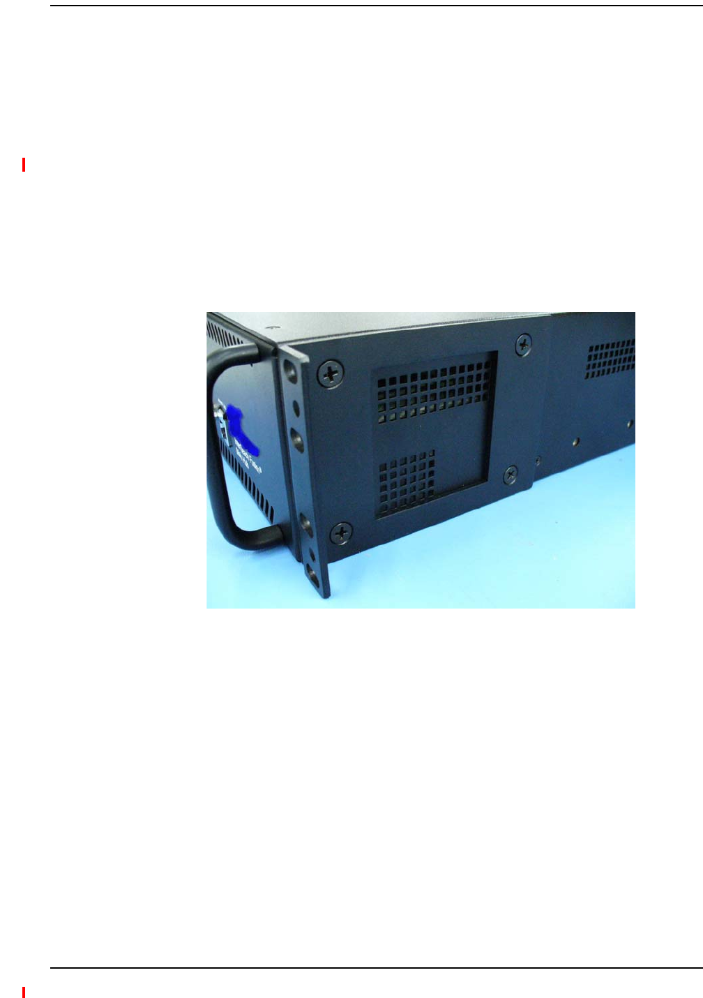
Figure21.Flush Mounting Bracket Detail
DothefollowingtoinstalltheHubinarack:
1Confirmthatthemountingscrewsmatchtherack’sthreads.(TheFusionWidebandMainHub
shipswith#10‐32mountingscrews;anothercommonrackthreadis#12‐24.)
2Insertspringnutsintorackwhereneededoruseexistingthreadedholes.
3PlacetheHubintotherackfromthefront.
4AligntheflangeholeswiththespringnutsinstalledinStep2.
5Insertthemountingscrewsintheappropriatepositionsintherack.
6Tightenthemountingscrews.
InstallingaFusionWidebandMainHubinaRack
Installing Fusion Wideband
Page 116 InterReach Fusion Wideband Installation, Operation, and Reference Manual
© 2013 TE Connectivity Ltd D-620616-0-20 Rev H • TECP-77-044 Issue 7 • May 2013
Usethescrewsprovidedtofastenthecablemanagertotherack,immediatelyaboveorbelowthe
MainHub.
NOTE: Themaximumweightthebracketcanholdis22.5kg(50lbs).
NOTE: ThebracketisdesignedtoaccommodateaFusionWidebandMainHub(12lbs.)oranExpansion
Hub(14.5lbs.).
NOTE: Thewallmountbracketshouldbesecurelymountedtowall,usingthefourkeyslotmounting
holesonthebracket.
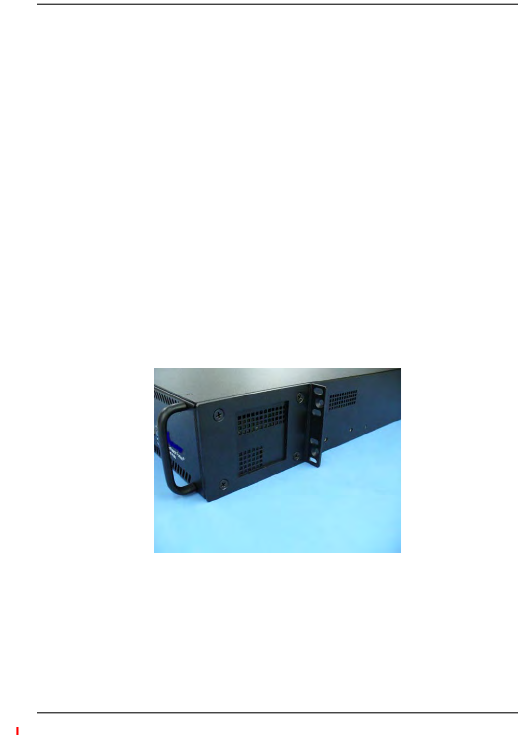
NOTE: Therack‐mountingbracketsontheFusionWidebandMainHubmustbemovedtotherecessed
mountingposition(showninFigure22)toallowfortherequired76mm(3in.)rearclearance.
1Attachthewallbracket(PN4712)towalltheusing#10PanHeadwoodscrews,1‐1/2”
minimumlengthformountinginwoodstudsor3/4“thickplywood.Thebracketmustbe
positionedsothattheHubwillbeinahorizontalpositionwhenitisinstalled.(Referto
Figure22.)
NOTE: Ifwallstudspacingof16”isnotavailable,pre‐install3/4”plywoodtothewall.Youcanthen
attachthebrackettotheplywoodusingthewoodscrews.
Figure22.Bracket Detail For Wall Mount Rack (PN 4712)
2RemovebothoftherackmountingbracketsfromtheHub.
3Reattacheachoftherackmountingbracketstotherecessedwallmountposition.
4InstalltheHubintherackusingtherackmountingscrews.
InstallinganOptionalCableManagerintheRack
InstallingaMainHubUsingthe12”Wall‐MountedRack(PN4712)
Installing a Fusion Wideband Main Hub
InterReach Fusion Wideband Installation, Operation, and Reference Manual Page 117
D-620616-0-20 Rev H • TECP-77-044 Issue 7 • May 2013 © 2013 TE Connectivity Ltd.
DothefollowingtoinstalltheHubdirectlytothewall:
1Pre‐install3/4”plywoodtothewall.
2Mountbothoftherackmountingbracketsusing#10‐32machinescrews,asshownin
Figure23.
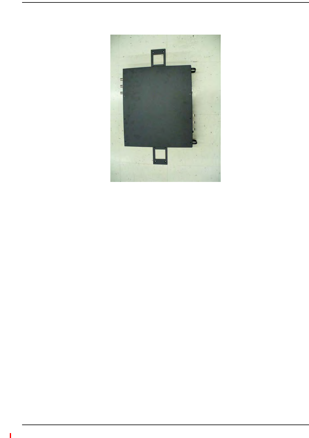
Figure23.Using Hub Rack-Mounting Brackets for Direct Wall Installation
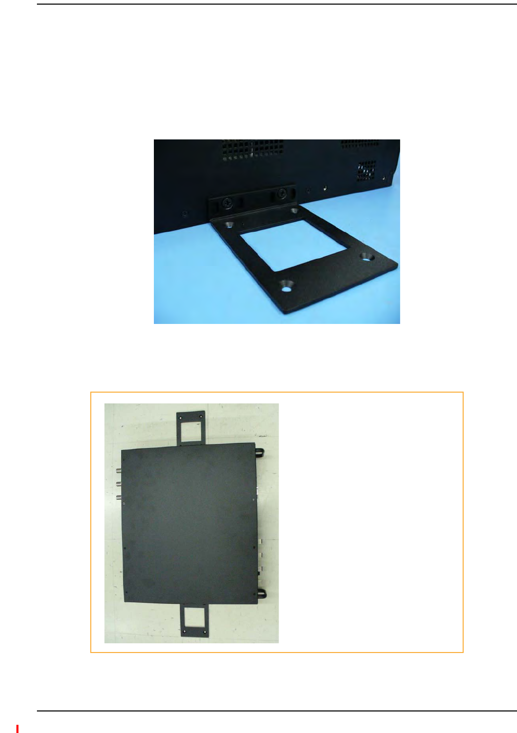
3AttachtheHubtothewallsothemountingbracketsareorientatedatthetopandbottomof
thewallmountedhub,asshowninFigure24.
Figure24.Installing Directly to the Wall
InstallingaFusionWidebandMainHubDirectlytotheWall
Use two #10 Pan Head wood screws,
1-1/2” length, to secure each bracket
to the plywood. In this orientation the
enclosure fans will face to the left.

Installing Fusion Wideband
Page 118 InterReach Fusion Wideband Installation, Operation, and Reference Manual
© 2013 TE Connectivity Ltd D-620616-0-20 Rev H • TECP-77-044 Issue 7 • May 2013
CAUTION! ObserveallFiberPortSafetyPrecautionslistedin“SafetyPrecautions”onpage109.
PreparingtheFiberCables
Dothefollowingbeforeconnectingthefibercables:
1Confirmthattheiropticallossdoesnotexceedthe3dBopticalbudget.
2Ifyouareusingfiberdistributionpanels,confirmthatthetotalopticallossoffibercable,from
theMainHubthroughdistributionpanelsandpatchcordstotheExpansionHub,doesnot
exceedtheopticalbudget.
3Makesurethefibercable’sconnectorsareSC/APC(angle‐polished).Usinganyother
connectortypewillresultindegradedsystemperformanceandmaydamagethe
equipment.(YoucanuseanSC/APCpigtailifthefibercable’sconnectorsarenotSC/APC.
Referto“FusionWidebandSplicingofFiberandPigtail”onpage145.Or,youcanchangethe
fiber’sconnectortoSC/APC.)
CleaningtheFiberPorts
YoucancleantheHub’sfiberportsusingcannedcompressedairorisopropylalcoholandfoam
tippedswabs.
•Ifusingcompressedair,theairmustbefreeofdust,water,andoil.
•Holdthecanlevelduringuse.
•Ifusingisopropylalcoholandfoamtippedswabs,useonly98%pureormorealcohol.
UsingCompressedAir
1Removetheport’sdustcap.
2Spraythecompressedairawayfromtheunitforafewsecondstocleanoutthenozzleand
thenblowdustparticlesoutofeachfiberport.
UsingIsopropylAlcohol
1Removetheconnector’sdustcap.
2Dipa2.5mmlint‐free,foam‐tippedswabinisopropylalcoholandslowlyinsertthetipintothe
connector.
3Gentlytwisttheswabtocleantheport.
4Insertadryswabintotheporttodryit.
5Additionally,youcanusecompressedairafterthealcoholhascompletelyevaporated.
ConnectingtheFiberCablestotheMainHub

Installing a Fusion Wideband Main Hub
InterReach Fusion Wideband Installation, Operation, and Reference Manual Page 119
D-620616-0-20 Rev H • TECP-77-044 Issue 7 • May 2013 © 2013 TE Connectivity Ltd.
CleaningtheFiberEnds
Besurethatthefibercable’sSC/APCconnectorsarecleanandfreeofdustandoils.Youneed
lint‐freecloths,isopropylalcohol,andcompressedair.
1Moistenalint‐freeclothwithisopropylalcohol.
2Gentlywipethefiberendwiththemoistenedcloth.
3Usingadrylint‐freecloth,gentlywipethefiberend.
4Spraythecompressedairawayfromtheconnectorforafewsecondstocleanoutthenozzle
andthenuseittocompletelydrytheconnector.
TestingtheFiberCables
Performcabletestingandrecordtheresults.TestresultsarerequiredforthefinalAs‐Built
Document.
ConnectingtheFiberCables
Thefibercableislabeledwitheither1or2,oriscolor‐coded.Inadditiontotheselabels,you
shouldaddacodethatidentifieswhichportontheMainHubisbeingusedandwhichExpansion
Hubthecablesareintendedfor.Thisdifferentiatestheconnectorsforproperconnectionbetween
theMainHubandExpansionHubs.
Forexample:
FirstpairtoMainHubport1:11(uplink),12(downlink);
SecondpairtoMainHubport2:21(uplink),22(downlink);
ThirdpairtoMainHubport3:31(uplink),32(downlink);andsoon.
NOTE: TheFusionWidebandOnePortMainHub(PN:FSN‐1‐MH‐1PandFSN‐2‐MH‐2‐1P)configuration
isacostreducedversionoftheFusionWidebandMainHubandsupportsonlyoneExpansionHub
(upto8RAUs).
Ifthefiberjumperislabeledwith1or2
1Connect1stoUPLINKportsontheMainHub.
2Connect2stoDOWNLINKportsontheMainHub.
3RecordwhichcablenumberandportnumberyouconnectedtoUPLINKandDOWNLINK.
ThisinformationisneededwhenconnectingtheotherendofthefibercabletotheExpansion
Hub’sfiberports.
ThefiberportLEDsshouldbeoff,indicatingthattheExpansionHub(s)arenotconnected.

Installing Fusion Wideband
Page 120 InterReach Fusion Wideband Installation, Operation, and Reference Manual
© 2013 TE Connectivity Ltd D-620616-0-20 Rev H • TECP-77-044 Issue 7 • May 2013
IftheFiberJumperisColor‐Coded
1Connect“blue”toUPLINKportsontheMainHub.
2Connect“red”toDOWNLINKportsontheMainHub.
3RecordwhichcolorandportnumberyouconnectedtoUPLINKandDOWNLINK.
ThisinformationisneededwhenconnectingtheotherendofthefibercabletotheExpansion
Hub’sfiberports.
ThefiberportLEDsshouldbeoff,indicatingthattheExpansionHub(s)arenotconnected.
CAUTION! Onlytrainedandqualifiedpersonnelshouldbeallowedtoinstallorreplacethisequipment.
ACPoweredMainHub
ToconnectACpowertoaMainHub:
1ConnecttheACpowercordtotheMainHub.
2PlugthepowercordintoanACpoweroutlet.
DCPoweredMainHubandExpansionHub
CAUTION! Theprotectiveearthconnectionshouldbeconnectedbeforeproceedingwithpower
connections.ConfirmtheDCpowersourceispoweredoffduringinstallation.Damagetohubs
mayresultifpowerisconnectedimproperly.
TheDCpoweredMainHubandExpansionHubareintendedtobepoweredbya+48VDCpower
source.Thehubsaredesignedfor14AWGto6AWGwiresizeconnections.UseonlyULlisted
AWMwire,rated600Vand90degreesC.
Ifwireslargerthan6AWGareneededfromtheDCpowersource,followlocalcodesforreducing
thewiresizeathubconnectionpoint.
Followlocalcodesforroutingofpowercablestopowersource.
TheunitshouldbeconnectedtoaDCbranchcircuitbreaker.Asuitabledisconnectdevicemust
beprovidedintheDCbranch,eitheracircuitbreakerorswitch,thatcanbeemployedto
disconnectpowertothesystemduringservicing.
MakingPowerConnections

Installing a Fusion Wideband Main Hub
InterReach Fusion Wideband Installation, Operation, and Reference Manual Page 121
D-620616-0-20 Rev H • TECP-77-044 Issue 7 • May 2013 © 2013 TE Connectivity Ltd.
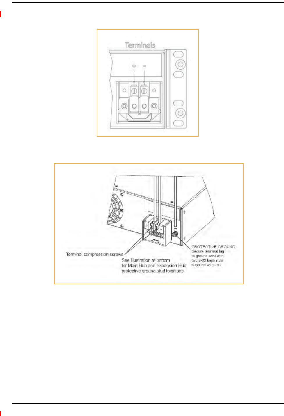
ToconnectDCpowertoaMainHuborExpansionHub:
1Strip5/8”(16mm)ofwireinsulationmaterialoffeachpowerwire.
2Insertthe+48VDCwireintothecompressionterminalatthe“+”location.
3Insertthe‐48VDCwireintothecompressionterminalatthe“‐”location.
4Barewireendsshouldbefullyinsertedintoterminal.
5Useaflatbladescrewdrivertofastenthewireinsidethecompressionterminal.
6FortheProtectiveGroundWire(Figure25),use14AWGminimumwirewitha#8‐32stud
sizeringlug.
Figure25.Protective Ground-Wire Connection
CAUTION! ThewarningcolorcodeofthepowercablesdependsonthecolorcodingoftheDCpowersource
installedatyoursite.ColorcodestandardsforDCwiringdonotexist.Toensurethatthecorrect
polarityisconnectedtothehubs,confirmtheconnectionofthepowercablestothe+(positive)
and‐(negative)leads(Figure25)atthepowersource.
Installing Fusion Wideband
Page 122 InterReach Fusion Wideband Installation, Operation, and Reference Manual
© 2013 TE Connectivity Ltd D-620616-0-20 Rev H • TECP-77-044 Issue 7 • May 2013
7UsetheillustrationsinFigure26andFigure27onpage122toconnectthepower.
Figure26.DC Terminals
Figure27.Locations of the Power Screws
Installing a Fusion Wideband Main Hub
InterReach Fusion Wideband Installation, Operation, and Reference Manual Page 123
D-620616-0-20 Rev H • TECP-77-044 Issue 7 • May 2013 © 2013 TE Connectivity Ltd.
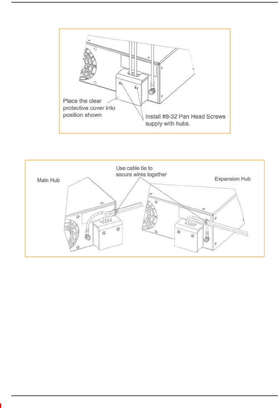
8InstalltheclearprotectivecoverwiththepanheadscrewsasshowninFigure28.
Figure28.Pan Head Screw Location
Figure29.Recommended Hub-Wire Routing
Installing Fusion Wideband
Page 124 InterReach Fusion Wideband Installation, Operation, and Reference Manual
© 2013 TE Connectivity Ltd D-620616-0-20 Rev H • TECP-77-044 Issue 7 • May 2013
OptionalConnectiontoDCPowerSource
Thisisanoptionalconnectionmethodusingringtonguelugsinsteadofthecompressionlugsthat
arepre‐mountedontheterminalblock.Usewireselectioninstructionspreviouslyexplained.
CAUTION! Beforeconnectingpowerwires,besurethepowersourceisshutoff,andthepowerswitchof
thehubsareintheOFFposition.Connectthegroundwiresbeforeconnectingthepowerwires.
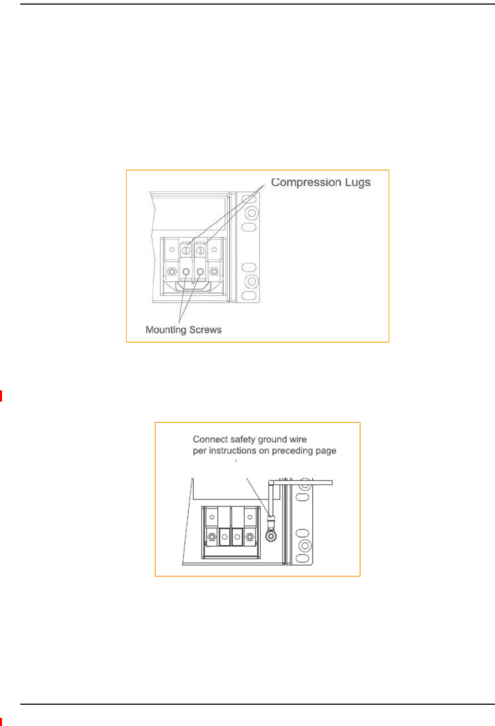
1Removetheexistingcompressionlugsbyfirstremovingthemountingscrewsasshownin
Figure30.
Figure30.Locations of the Compression Lug and Mounting Screw
2ConnectthesafetygroundwireaspreviouslyexplainedandshowninFigure31.Use14AWG
minimumwirewitha#8‐32studsizeringlugasshowninFigure32onpage125.
Figure31.Grounding Wire Connection
Installing a Fusion Wideband Main Hub
InterReach Fusion Wideband Installation, Operation, and Reference Manual Page 125
D-620616-0-20 Rev H • TECP-77-044 Issue 7 • May 2013 © 2013 TE Connectivity Ltd.
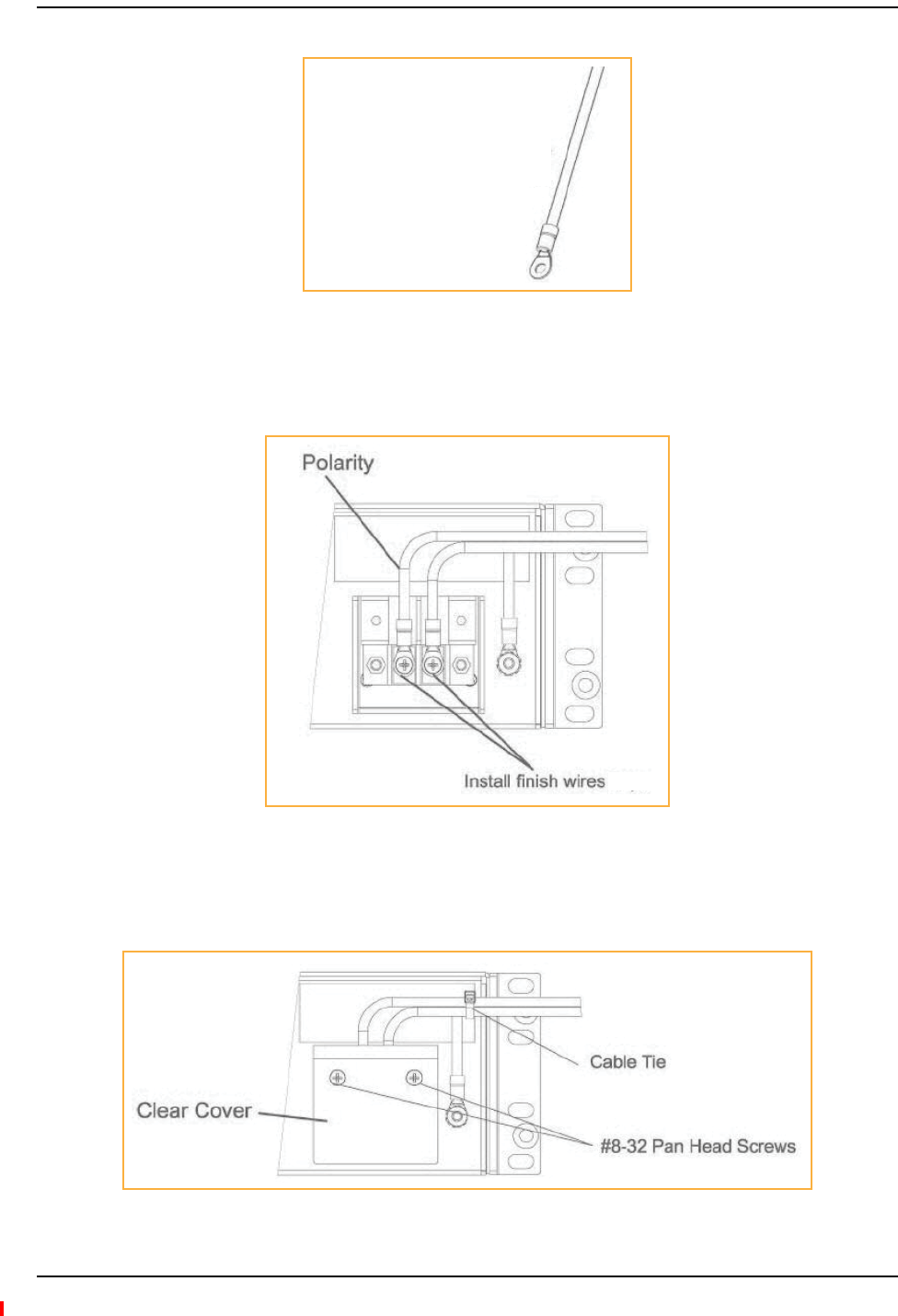
Figure32.Power Wires and Studs
3Installthefinishwiresusingtheproperpolarityandsecurethemwith#8‐32panheadscrews
previouslyremovedasillustratedinFigure33.
Figure33.Wire Polarity
4Attachtheclearprotectivecoverandsecureitwiththetwo#8‐32panheadscrewssupplied
withtheHubasshowninFigure34.
Figure34.DC Installation
Power Wires
14 AWG minimum wire
with a #8-32 stud size ring
lug.

Installing Fusion Wideband
Page 126 InterReach Fusion Wideband Installation, Operation, and Reference Manual
© 2013 TE Connectivity Ltd D-620616-0-20 Rev H • TECP-77-044 Issue 7 • May 2013
1ConnecttheACorDCpowerasexplainedin“MakingPowerConnections”onpage120.
2TurnonthepowertotheMainHubandcheckthatalltheLEDlampsarefunctioningproperly.
Uponpower‐up,theLEDsblinksforfivesecondsasavisualcheckthattheyarefunctioning.
Afterthefive‐secondtest,LEDstatesduringpoweronwillvary,dependingonwhether
ExpansionHubsareconnected.RefertoTable87forpossiblecombinations.
PoweringontheMainHub
Table87.TroubleshootingMainHubLEDsDuringInstallation
During
Installation
Power On
LED State Action Impact
1Main Hub
power is On
with no
Expansion
Hubs
connected.
POWER Off Check AC power; check that the Main Hub power-on
switch is on; replace the Main Hub
The Main Hub is not
powering on.
POWER Red Replace the Main Hub The power supply is
out-of-specification.
PORT LEDs are on
but didn’t blink
through all
states
Replace the Main Hub. The micro controller is
not resetting properly;
flash memory
corrupted.
PORT Red The port is unusable; replace the Main Hub when
possible.
Fiber sensor fault, do
not use the port.
Off
2Main Hub
power is On
with
Expansion
Hubs
connected
and powered
on.
PORT Off • If the port LEDs do not illuminate, check the fiber
uplink for excessive optical loss.
• If Expansion Hub’s DL Status LED is red:
- Verify that the fiber is connected to the
correct port (that is, uplink/downlink)
- Swap the uplink and downlink cables.
• Connect the fiber pair to another port. If the
second port’s LEDs do not illuminate Green/Red,
replace the Main Hub.
- If the second port works, flag the first port as
unusable; replace the Main Hub when
possible.
No uplink optical
power, the Expansion
Hub is not recognized
as being present.
No communication
with the Expansion
Hub.
PORT Red (60 ppm) • If the Expansion Hub DL Status LED is red, check
the downlink fiber cable for excessive optical loss.
• Connect the fiber pair to another port. If the
second port’s LEDs do not illuminate Green/Red,
replace the Main Hub.
- If the second port works, flag the first port as
unusable; replace the Main Hub when
possible.
No communication
with the Expansion
Hub.
PORT Red The Expansion Hub or connected RAU reports a fault
Use AdminManager to determine the problem.
The Expansion Hub or
one or more RAUs are
off-line.

Installing Expansion Hubs
InterReach Fusion Wideband Installation, Operation, and Reference Manual Page 127
D-620616-0-20 Rev H • TECP-77-044 Issue 7 • May 2013 © 2013 TE Connectivity Ltd.
INSTALLINGEXPANSIONHUBS
TheExpansionHub(2Uhigh)canbeinstalledinastandard19in.(483mm)equipmentrackor
inawall‐mountableequipmentrackthatisavailablefromTE.Allowaclearanceof76mm(3in.)
frontandrearand51mm(2in.)sidesforaircirculation.Notopandbottomclearanceisrequired.
CAUTION! InstallExpansionHubsinindoorlocationsonly.
NOTE: Thefollowingproceduresassumethatthesystemisnewfromthefactoryandthatithasnot
beenprogrammedwithbands.Ifyouarereplacingcomponentsinapre‐installedsystemwith
eithernewunitsorunitsthatmayalreadybeprogrammed(forexample,re‐usingunitsfrom
anothersystem),referto“ReplacingFusionWidebandComponents”onpage175.
Dothefollowingtoinstallthehubinarack:
1Confirmthatthemountingscrewsmatchtherack’sthreads.(TheExpansionHubisshipped
with#10‐32mountingscrews;anothercommonrackthreadis#12‐24.)
2Insertspringnutsintotherackwhereneededoruseexistingthreadedholes.
3PlacetheExpansionHubintotherackfromthefront.
4AligntheflangeholeswiththespringnutsinstalledinStep2.
5Insertthemountingscrewsintheappropriatepositionsintherack.
6Tightenthemountingscrews.
CAUTION! Themaximumweighttherackcanholdis22.5kg(50lbs).
NOTE: Therack(PN4712)is305mm(12in.)deep.TheExpansionHubis381mm(15in.)deep.
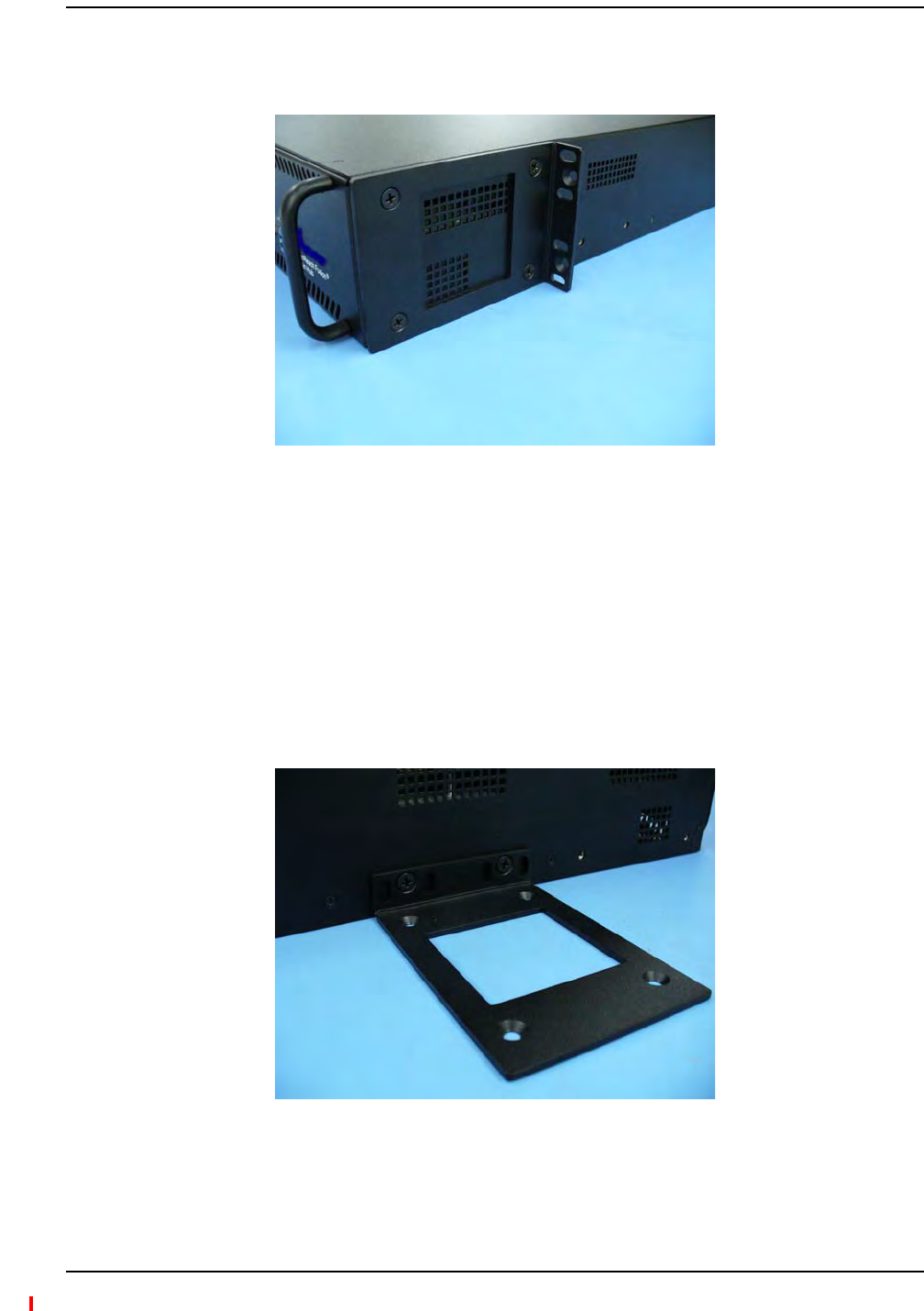
1MovetherackmountingbracketsontheExpansionHub,asshowninFigure35)tothecenter
mountingpositiontoallowforthe76mm(3in.)rearclearancethatisrequired.
2Attachtheequipmentracktothewallusingthescrewsthatareprovided.
3TherackmustbepositionedsothattheExpansionHubwillbeinahorizontalpositionwhen
itisinstalled.
NOTE: Ifwallstudspacingof16”isnotavailable,TErecommendsthat3/4”plywoodbepre‐installedto
thewall.Youcanthenattachthebrackettotheplywoodusingthewoodscrews.
InstallinganExpansionHubinaRack
InstallinganExpansionHubUsingthe12”Wall‐MountedRack
Installing Fusion Wideband
Page 128 InterReach Fusion Wideband Installation, Operation, and Reference Manual
© 2013 TE Connectivity Ltd D-620616-0-20 Rev H • TECP-77-044 Issue 7 • May 2013
4RemovebothoftherackmountingbracketsfromtheHub.
5Reattacheachoftherackmountingbracketstotherecessedwallmountposition(Figure35).
Figure35.Bracket Detail For Wall Mount Rack (PN 4712)
6InstalltheHubintherackusingtherackmountingscrews.
7Tightenthemountingscrews.
DothefollowingtoinstalltheHubdirectlytothewall:
1Pre‐install3/4”plywoodtothewall.
2Mountbothoftherackmountingbracketsusing#10‐32machinescrews(seeFigure36).
Figure36.Using Hub Rack-Mounting Brackets for Direct Wall Installation
InstallinganExpansionHubDirectlytotheWall
Installing Expansion Hubs
InterReach Fusion Wideband Installation, Operation, and Reference Manual Page 129
D-620616-0-20 Rev H • TECP-77-044 Issue 7 • May 2013 © 2013 TE Connectivity Ltd.
3AttachtheHubtothewallsothemountingbracketsareorientatedatthetopandbottomof
thewallmountedhub.(RefertoFigure37.)
Figure37.Installing Directly to the Wall
4Leavethedustcapsonthefiberportsuntilyouarereadytoconnectthefiberopticcables.
Usethescrewsprovidedtofastenthecablemanagertotherack,immediatelyaboveorbelowthe
ExpansionHub.
1ConnecttheACorDCpowerasexplainedin“MakingPowerConnections”onpage7‐18.
2TurnonthepowertotheExpansionHubandcheckthatalltheLEDlampsarefunctioning
properly.
Uponpower‐up,theLEDsblinksforfivesecondsasavisualcheckthattheyarefunctioning.
Afterthefive‐secondtest:
•ThePOWERandUL STATUSLEDsshouldbegreen.
•Iftheuplinkfiberisnotconnected,theUL STATUS LEDturnsredindicatingthatthereisno
communicationwiththeMainHub.
•TheE-HUB STATUSandDL STATUS LEDsshouldbered.
•AllportLEDsshouldbeoffbecausenoRAUsareconnectedyet.
InstallinganOptionalCableManagerintheRack
PoweringontheExpansionHub

Installing Fusion Wideband
Page 130 InterReach Fusion Wideband Installation, Operation, and Reference Manual
© 2013 TE Connectivity Ltd D-620616-0-20 Rev H • TECP-77-044 Issue 7 • May 2013
CAUTION! ObserveallFiberPortSafetyPrecautionslistedin“SafetyPrecautions”onpage109.
PreparingtheFiberCables
1Confirmthattheiropticallossdoesnotexceed3dBopticalbudget.RLislessthan‐60dB.
2Iffiberdistributionpanelsareused,confirmthatthetotalopticallossoffibercable,fromthe
MainHubthroughdistributionpanelsandpatchcordstotheExpansionHub,doesnotexceed
theopticalbudget.
3Makesurethefibercable’sconnectorsareSC/APC(angle‐polished).Usinganyother
connectortypewillresultindegradedsystemperformanceandmaydamagethe
equipment.(YoucanuseanSC/APCpigtailifthefibercable’sconnectorsarenotSC/APC,
referto“FusionWidebandSplicingofFiberandPigtail”onpage145,orreplacethe
connectors.)
ConnectingtheFiberCables
Thefibercableislabeledwitheither1or2,oriscolor‐coded.Forproperconnectionbetweenthe
MainHubportsandtheExpansionHubports,refertothenumberingorcolor‐codedconnections
yourecordedwheninstallingtheMainHub(s).
IftheFiberJumperIsLabeledwith1or2
1Connect2toDOWNLINKontheExpansionHub.
TheDL STATUSLEDshouldturngreenassoonasyouconnectthefiber.Ifitdoesnot,thereisa
downlinkproblem.Makesureyouareconnectingthecorrectcabletotheport.
2Connect1toUPLINKonExpansionHub.
TheUL STATUSLEDturnsgreenonthefirstMainHubcommunication.Itmaytakeupto20
secondstoestablishcommunication.
TheExpansionHub’sE-HUB STATUSLEDturnsgreenwhentheMainHubsendsitthefrequency
bandcommand.
3IftheUL STATUSandE-HUB STATUSLEDsdonotturngreen/green,checktheMainHubLEDs;
seeStep2inTable87onpage126.
ConnectingtheFiberCablestotheExpansionHub

Installing Expansion Hubs
InterReach Fusion Wideband Installation, Operation, and Reference Manual Page 131
D-620616-0-20 Rev H • TECP-77-044 Issue 7 • May 2013 © 2013 TE Connectivity Ltd.
IftheFiberJumperIsColor‐Coded
1Connect“red”toDOWNLINKonExpansionHub.
TheDL STATUSLEDshouldturngreenassoonasyouconnectthefiber.Ifitdoesnot,thereisa
downlinkproblem.Makesureyouareconnectingthecorrectcabletotheport.
2Connect“blue”toUPLINKonExpansionHub.
TheUL STATUSLEDturnsgreenonthefirstMainHubcommunication.Itmaytakeupto20
secondstoestablishcommunication.
TheExpansionHub’sE-HUB STATUSLEDturnsgreenwhentheMainHubsendsitthefrequency
bandcommand.
3IftheUL STATUSandE-HUB STATUSLEDsdonotturngreen/green,checktheMainHubLEDs;
seeStep2inTable87onpage126.
1Verifythatthecablehasbeentestedandthetestresultsarerecorded.Thisinformationis
requiredfortheAs‐BuiltDocument.
2VerifythatonlycaptivecenterpinFconnectorsareusedonthesolidcoppercenterconductor
CATVcablefromCommScope(orequivalent).
3VerifythattheCATVcableislabeledwith:
•FusionWidebandExpansionHubportnumberbeingused
•RAUidentifier
•Carrier(formultipleoperatorsystems)
4ConnecttheCATVcablestotheFportsaccordingtothelabelsonthecables.
TheSTATUSLEDsshouldbeoffbecausetheRAUsarenotconnectedattheotherendofthe
CATVcable.
5Recordwhichcableyouareconnectingtowhichport(thatis,fromthelabelonthecable),as
thisinformationisrequiredfortheAs‐BuiltDocument.
6Tie‐offthecablesorusetheoptionalcablemanagertoavoiddamagingtheconnectors
becauseofcablestrain.
Connectingthe75OhmCATVCables

Installing Fusion Wideband
Page 132 InterReach Fusion Wideband Installation, Operation, and Reference Manual
© 2013 TE Connectivity Ltd D-620616-0-20 Rev H • TECP-77-044 Issue 7 • May 2013
•AllExpansionHubPORTLEDswithRAUsconnectedshouldindicateGreen/Red.Thisindicates
thattheRAUispoweredonandcommunicationhasbeenestablished.
•TheExpansionHubUL STATUSLEDshouldbeGreen.
TroubleshootingExpansionHubLEDsDuringInstallation
Table88.TroubleshootingExpansionHubLEDsDuringInstallation
During
Installation
LED State Action Impact
1Expansion Hub
power is On
and no RAUs
are connected
POWER Off Check AC power; make sure the
Expansion Hub power-on switch is
on; replace the Expansion Hub.
The Expansion Hub is not
powering on.
PORT LEDs are on but didn’t
blink through all
states.
Replace the Expansion Hub. The Microcontroller is not
resetting properly; flash
memory corrupted.
PORT Flashing Red
(6 PPM)
Port unusable; replace the
Expansion Hub when possible.
Current sensor fault; do not
use the port.
UL STATUS Red, after power-up
blink
Replace the Expansion Hub. The Expansion Hub laser is not
operational; no uplink between
the Expansion Hub and Main
Hub.
UL STATUS Red Check the Main Hub LEDs—refer to
Step 2 in Table 87 on page 126.
Use AdminBrowser to determine the
problem.
No communication with Main
Hub.
DL STATUS Red Check the downlink fiber for optical
power; verify that the cables are
connected to correct ports (that is,
uplink/downlink)
Check the Main Hub LEDs—refer to
Step 2 in Table 87 on page 126.
No downlink between the
Expansion Hub and Main Hub.
2Expansion Hub
power is On
and RAUs are
connected
PORT Off Check the CATV cable. Power is not getting to the
RAU.
PORT Flashing Red
(60 PPM)
Test the CATV cable. If the cable
tests OK, try another port. If the
second port’s LEDs are Red/Off,
replace the RAU. If the second RAU
doesn’t work; replace the Expansion
Hub.
Power levels to RAU are not
correct; communications are
not established.
If the second port works, flag
the first port as unusable;
replace EH when possible.
PORT Red Use AdminBrowser to determine the
problem.
RAU is off-line.

Installing RAUs
InterReach Fusion Wideband Installation, Operation, and Reference Manual Page 133
D-620616-0-20 Rev H • TECP-77-044 Issue 7 • May 2013 © 2013 TE Connectivity Ltd.
INSTALLINGRAUS
CAUTION! InstallRAUsinindoorlocationsonly.Donotconnectanantennathatisinstalledinanoutdoor
locationtoanRAU.Foroutdoorinstallations,aprotectiveenclosureisrequired.
NOTE: Thefollowingproceduresassumethatthesystemisnewfromthefactoryandthatithasnot
beenprogrammedwithbands.Ifyouarereplacingcomponentsinapre‐installedsystemwith
eithernewunitsorunitsthatmayalreadybeprogrammed(forexample,re‐usingunitsfrom
anothersystem),referto“ReplacingFusionWidebandComponents”onpage175.
MountallRAUsinthelocationsmarkedonthefloorplans.
•Install800iDENand850/1900MHzRAUssothattheirantennaswillbeseparatedbyenough
spacetoreducesignalinterferencebetweenthe800and850bands.Referto“800/850MHz
IsolationRequirements”onpage134forrecommendeddistancebetweenantennas.
•Youcanplacetheunit,withoutitsfasteninghardware,onaflatsurface,suchasashelf,desk,
cabinet,oranyotherhorizontalsurfacethatallowsstableplacementwiththemountingbase
facingdowntothemountingsurface.Formountingtootherlocations(thatis,walls,ceilings,
poles)theRAUmustbesecurelymountedusingthe4slottedmountingholesprovidedwith
#6diameterfasteners.Thismethodofmountingmustsecurelyholdaminimumof7lbs.load.
•AttachtheRAUsecurelytoastationaryobject(thatis,awall,pole,orceilingtile).
•Forproperventilation:
–Keepatleast76mm(3in.)clearancearoundtheRAUtoensureproperventing.
–DonotstackRAUsontopofeachother.
–AlwaysmounttheRAUwiththesolidface(containingthemountingholes)againstthe
mountingsurface.
Refertothemanufacturer’sinstallationinstructionstoinstallpassiveantennas.
Location
Passiveantennasareusuallyinstalledbelowtheceiling.Iftheyareinstalledabovetheceiling,you
mustconsidertheadditionallossduetotheceilingmaterialwhenestimatingtheantenna
coveragearea.
InstallingRAUs
InstallingPassiveAntennas
Installing Fusion Wideband
Page 134 InterReach Fusion Wideband Installation, Operation, and Reference Manual
© 2013 TE Connectivity Ltd D-620616-0-20 Rev H • TECP-77-044 Issue 7 • May 2013
800/850MHzIsolationRequirements
WhendeployinganyRFsystem,givespecialattentiontopreventingreceiverblockingor
desensitizationbyout‐of‐bandtransmitters.Typically,sharpfiltersinthereceiverfront‐endwill
reducetheinterferingtransmitterstotolerablelevels.Inselectcases,theinterferersmayoccupy
afrequencybandthatisdirectlyadjacenttothereceivingbandandcannotbeadequatelyrejected
byfiltering.Theonlyrecourseinthesesituationsistoprovidesufficientisolationbyphysically
separatingtheinterferingtransmittersandreceivers.
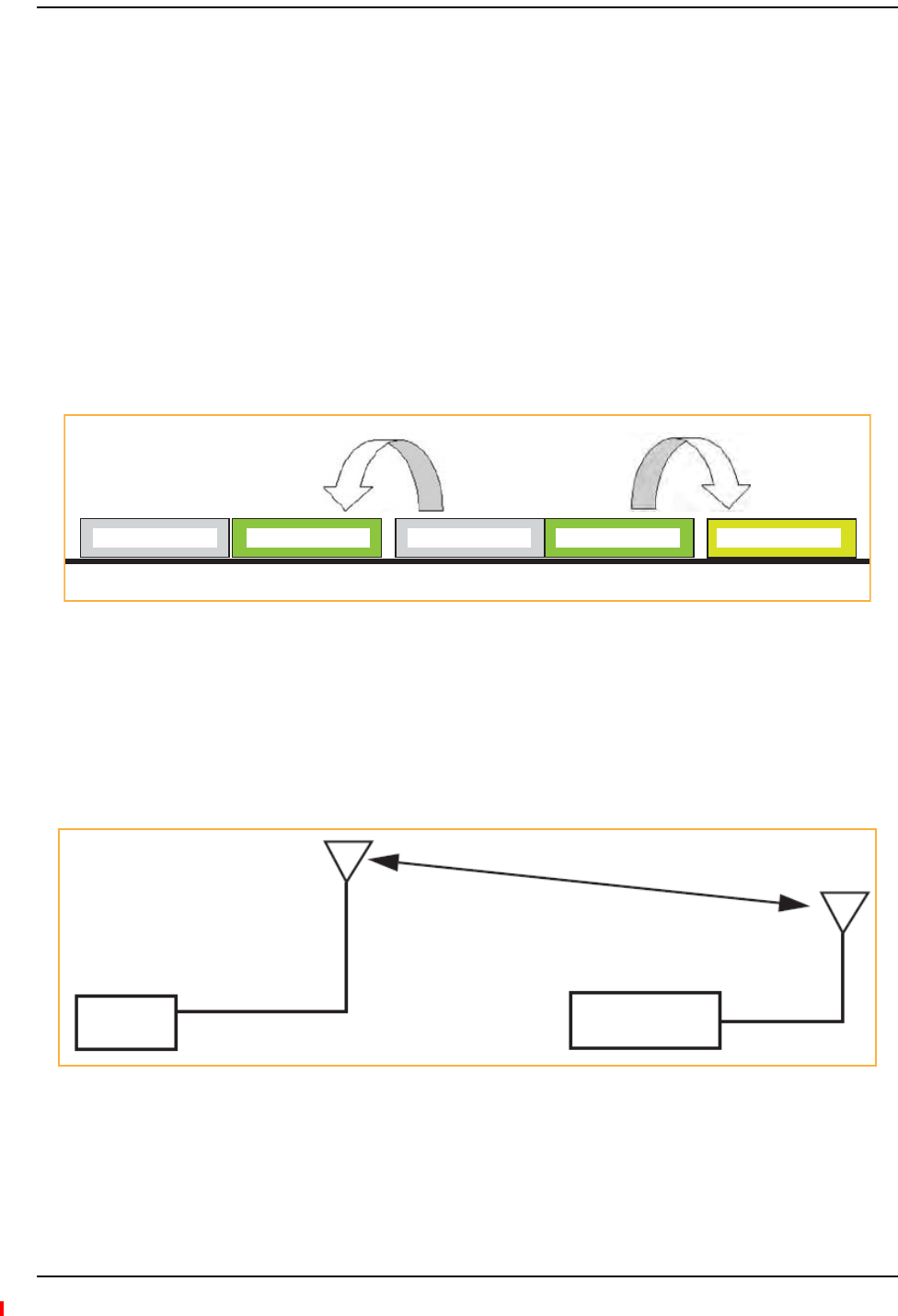
iDENoccupiesspectrumatboth800MHzand900MHz(Tx:851–869/Rx:806–824and
Tx:935–941/Rx:896–902),whiletheCellularAandBcarriersshareasingle850MHzblock
(Tx:869–894/Rx:824–849).Thecombinationofthesefrequencybands,800/900MHziDENand
850MHzCellular,resultinuplink(BTSreceive)bandsthatareadjacenttodownlink(BTS
transmit)bands.Figure38depictsthesenearlycontiguousbands,witharrowsindicatingthe
interferingdownlinkandreceivinguplinkbands.
Figure38.800/850 MHz Spectrum
Installationofanin‐buildingdistributedantennasystem(DAS)toprovidecoverageforboth
800/900MHziDENand850MHzCellularmustaccountforthesedownlink‐to‐uplink
interferenceissuesandprovideadequateisolation.
TEoffersthefollowingguidelinestowardachievingtheproperamountofisolationwhen
deployingTEFusionWidebandDASproducts.
Figure39.Fusion Wideband 800/850/1900 MHz RAU Antenna Placement Guideline
824 849 851 869 894 896 - 902
800/iDEN Uplink 850 Cellular Uplink 800/iDEN Downlink 850 Cellular Downlink 900/iDEN Uplink
Band 1
800 MHz
Band 2/3
850/1900 MHz
>d

Installing RAUs
InterReach Fusion Wideband Installation, Operation, and Reference Manual Page 135
D-620616-0-20 Rev H • TECP-77-044 Issue 7 • May 2013 © 2013 TE Connectivity Ltd.
800MHziDENDownlinkand850MHzCellularUplink
A2MHzfrequencygap(851–849MHz)separatesthe800iDENdownlinkand850Cellular
uplinkfrequencybands.Becauseofthisnarrowspacing,800iDENdownlinkintermodulation
productsmayfallwithinthe850Cellularuplinkband.Inaddition,800iDENdownlinksignals
neartheloweredgeofthebandat851MHzmaycausethe850Cellularuplinkautomaticlevel
control(ALC)circuitryintheRAUtoengageandtherebyreduceuplinkgain.
Topreventeitheroftheseconditions,usethefollowingguidelines:
•In‐band800iDENintermodulationproducts<‐90dBm
•Lowerfrequency800iDENsignals<–30dBmforFusionWideband
GivenatypicalDASconfiguration(4iDENcarriers,omni‐directionalantennas,lineofsight),these
guidelinestranslatetoanantennaspacing(d1)of6–9meters.
850MHzCellularDownlinkand900MHziDENUplink
A2MHzfrequencygap(896–894MHz)separatesthe850Cellulardownlinkand900iDEN
uplinkfrequencybands.Becauseofthisnarrowspacing,850Cellulardownlinkintermodulation
productsmayfallwithinthe900iDENuplinkband.Inaddition,850Cellulardownlinksignals
neartheupperedgeofthebandat894MHzmaycausethe900iDENuplinkALCtoengageand
therebyreduceuplinkgain.
Topreventeitheroftheseconditions,usethefollowingguidelines:
•In‐band850Cellularintermodulationproducts<‐90dBm
•Upperfrequency850Cellularsignals<–30dBmforFusionWideband
GivenatypicalDASconfiguration(6CDMAcarriersforFusionWideband,omni‐directional
antennas,lineofsight),theseguidelinestranslatetoanantennaspacing(d2)of8‐14meters.
SpacingbetweenRAUsFSN‐8519‐1andFSN‐809019‐2shouldbeinarangeoffrom8to14
meters.
Connectapassivemulti‐bandantennatotheNconnectorontheRAUusingcoaxialcablewiththe
leastamountoflosspossible.
CAUTION! Firmlyhand‐tightentheNconnector–DONOTover‐tightentheconnector.
ConnectingtheAntennatotheRAU

Installing Fusion Wideband
Page 136 InterReach Fusion Wideband Installation, Operation, and Reference Manual
© 2013 TE Connectivity Ltd D-620616-0-20 Rev H • TECP-77-044 Issue 7 • May 2013
1Verifythatthecablehasbeentestedandthetestresultsarerecorded.Thisinformationis
requiredfortheAs‐BuiltDocument.
2Verifythatonlycaptivecenterpin75OhmType‐Fconnectorsareusedonthesolidcopper
centerconductorCATV75Ohmcable.
3VerifythattheCATVcableislabeledwith:
•FusionWidebandMainHubportnumberbeingused
•RAUidentifier
•Carrier(formultipleoperatorsystems)
4ConnecttheCATVcablestotheFfemaleportontheRAUaccordingtothelabelonthecable.
PowerissuppliedbytheFusionWidebandMainHubovertheCATVcableconductors.Upon
powerup,theLEDswillblinkfortwosecondsasavisualcheckthattheyarefunctioning.After
thetwo‐secondtest:
•TheLINKLEDshouldbegreenindicatingitisreceivingpowerandcommunicationsfrom
theFusionWidebandMainHub.
•TheALARMLEDshouldbereduntiltheFusionWidebandMainHubissuestheband
command,withinabout20seconds,thenitshouldbegreen.
5RecordwhichcableyouareconnectingtotheRAU(fromthelabelonthecable);this
informationisrequiredfortheAs‐BuiltDocument.
6Tie‐offcablesorusetheoptionalcablemanagertoavoiddamagingtheconnectorsbecauseof
cablestrain.
ConnectingtheCATVCable

Installing RAUs
InterReach Fusion Wideband Installation, Operation, and Reference Manual Page 137
D-620616-0-20 Rev H • TECP-77-044 Issue 7 • May 2013 © 2013 TE Connectivity Ltd.
TroubleshootingUsingRAULEDsDuringInstallation
TheLINKLEDshouldbegreenandremaingreenforlongerthan90seconds.TheALARM LEDsare
redwhenthesystembandhasnotbeenprogrammed.
Table89.TroubleshootingRAULEDsDuringInstallation
During
Installation
LED State Action Impact
The RAU is connected to
the Fusion Wideband
Expansion Hub, which is
powered on
LINK Off Check CATV cable. No power to the RAU.
ALARM Off
LINK Green • Check CATV cable
•Check the Main Hub LEDs—refer to
Step 2 in Table 87 on page 126.
• Use AdminBrowser to determine the
problem.
The RAU is off-line.
ALARM Red
LINK Red from
green, after
cables are
connected for
60 seconds
• Check CATV cable.
• Check the Hub LEDs.
• Use AdminBrowser to determine the
problem.
No communications between
the RAU and the Hub.
ALARM Red

Installing Fusion Wideband
Page 138 InterReach Fusion Wideband Installation, Operation, and Reference Manual
© 2013 TE Connectivity Ltd D-620616-0-20 Rev H • TECP-77-044 Issue 7 • May 2013
CONFIGURINGTHEFUSIONWIDEBANDSYSTEM
Beforethesystemcanoperateproperly,useAdminBrowsertoprogramtheFusionWideband
MainHubwiththefrequencybandsthataretobedistributed.TheHubmustbeprogrammedwith
thesamefrequenciesastheRAUused.
TheAdminBrowsersoftware,describedintheAdminBrowserUserManual(PND‐620607‐0‐20),
mustberunningonaPC/laptop.
NOTE: Thefrequencybandsshouldautomaticallybesetonpowerupandthisstepshouldnotbe
required.
NOTE: CrossoverEthernetcablewithmaleconnectorsrequired.
NOTE: Thefollowingproceduresassumethatthesystemisnewfromthefactoryandthatithasnot
beenprogrammedwithbands.Ifyouarereplacingcomponentsinapre‐installedsystemwith
eithernewunitsorunitsthatmayalreadybeprogrammed(forexample,re‐usingunitsfrom
anothersystem),referto“ReplacingFusionWidebandComponents”onpage175.
1ConnecttheACpowercordtotheHub.
CAUTION! MakesuretheHubisgroundedthroughthegroundlugontheACpowerandtheframeground
lugasrequired.ThewarrantydoesnotcoverdamagecausedwhenanungroundedHubis
poweredon.
2PlugthepowercordintoanACpoweroutlet.
3VerifythatallcablesareproperlyconnectedontheHub.
4TurnonthepowertotheHub.
AllLEDsblinkthroughthepowerupsequence.AteachportwhereanRAUisdetected
(drawingcurrent),theportLEDslightsgreen.TheFusionWidebandSTATUSLEDisorange
duringsystembootandshouldturngreenafterabout90secondsifitfindsnofaults.This
stateindicatestheband’sarenotprogrammedandprovidesfeedbackonthestatusofthe
RAUconnections.
TheLEDsblinkfor20secondsasavisualcheckthattheyarefunctioning.
5Connectthecross‐overEthernetcabletothePC/laptopandthentotheRJ-45 100-BASE-T port
ontheHub’sfrontpanel.
ConnectingthePCtotheMainHubtoRunAdminBrowser
Configuring the Fusion Wideband System
InterReach Fusion Wideband Installation, Operation, and Reference Manual Page 139
D-620616-0-20 Rev H • TECP-77-044 Issue 7 • May 2013 © 2013 TE Connectivity Ltd.
1ConnecttheprovidedTCP/IPcrossovercabletothelaptopandthentotheAdmin/LANRJ-45
portontheFusionWidebandMainHub’sfrontpanel.
2TurnonthelaptopandstarttheFusionWidebandMainHub.
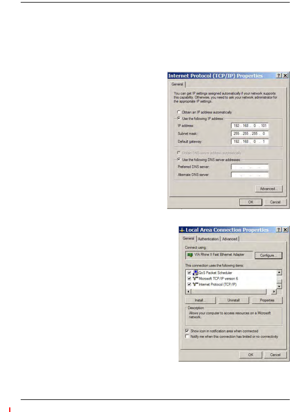
3Dooneofthefollowing:
•ForWindows2000:
aRight‐clickMy Network Placesand
selectProperties.
bHighlightInternet Protocol (TCP/IP)
andclickProperties.Ascreensimilar
totheoneshowntotherightopens.
•ForwindowsXP:
aClickStart>Settings>Network
Connections>LocalAreaConnection.The
windowshowntotherightopens.
bIntheThis connection uses the following
items,scrolldowntoandselectInternet
Protocol (TCP/IP)andclickProperties.
ProgrammingtheMainHubUsingAdminBrowser
Installing Fusion Wideband
Page 140 InterReach Fusion Wideband Installation, Operation, and Reference Manual
© 2013 TE Connectivity Ltd D-620616-0-20 Rev H • TECP-77-044 Issue 7 • May 2013
4MakenoteofthecurrentIPaddress,Subnetmask,andDefaultgateway,iftheyareconfigured.
Youwillneedtore‐enterthemafteryouhaveconfiguredtheFusionWidebandMainHub.
5SelectUse the following IP address.
6ChangetheIP addressto192.168.0.101
7ChangetheSubnet maskto255.255.255.0
8ChangetheDefault gateway to192.168.0.1
9ClickOKtwice.Youmaybeaskedifyouwanttorebootyourcomputer.Ifso,clickYes.
UsingAdminBrowser
ToaccessFusionWidebandusingAdminBrowser,usethefollowingsteps:
1MakesuretheMainHubStatusLEDisgreen.
2TypethefollowingintheURLline:
Https://192.168.0.100
3ClickGo.
4WhenAdminBrowserappears,loginusingthedefaultuserID:operator,andthedefault
password:password.
5WhenAdminBrowserappears,loginusingthedefaultuserIDandthepassword,whichare
respectively:operatorandpassword.
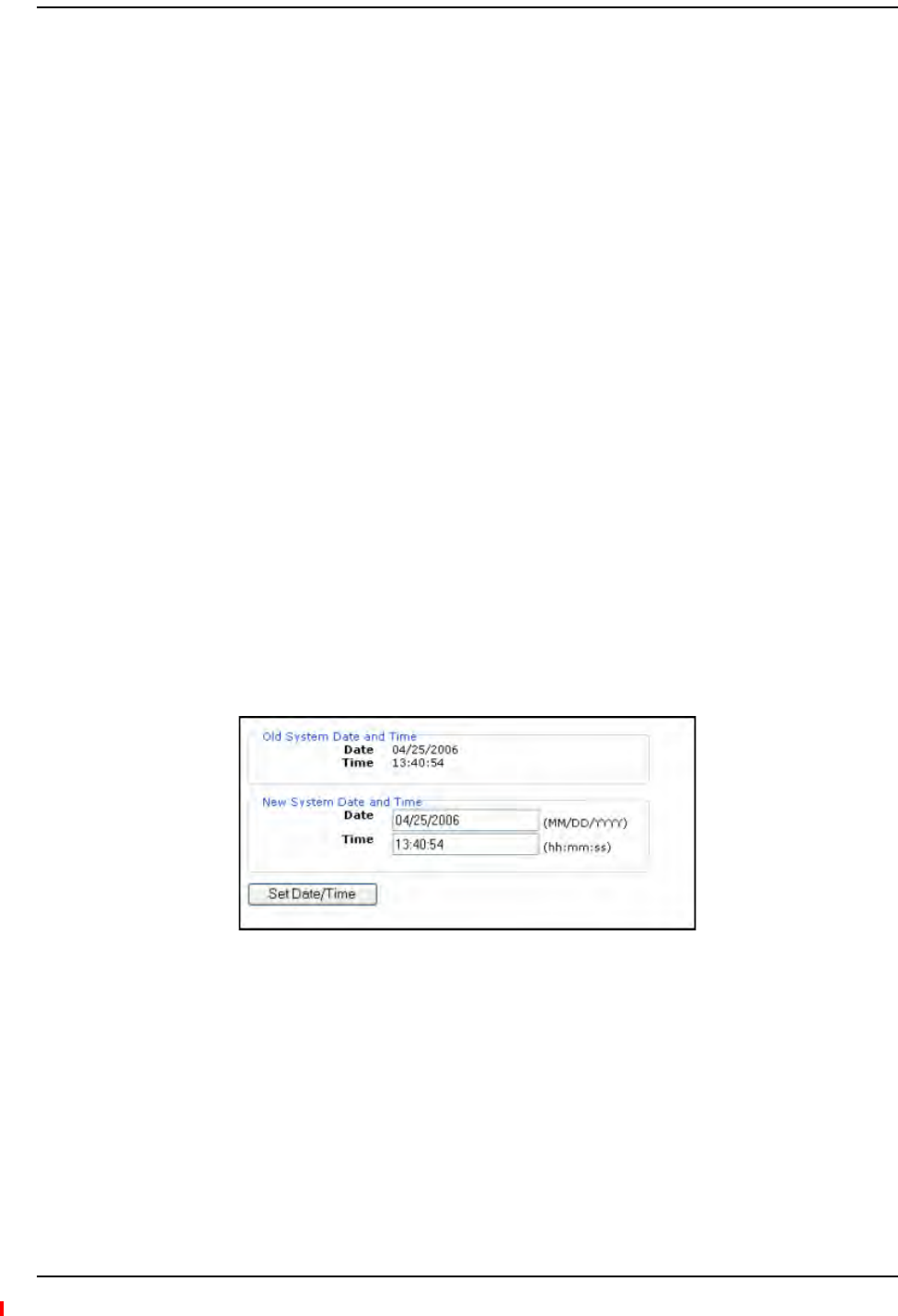
6ClickSystemConfigurationandthenclickSetDate/Time.Apagesimilartooneshownbelow
opens.
7EnterthedesiredtimeanddateintheformatindicatedonthepageandclickSetDate/Time.
Apageappearsrequiringyoutorebootthesystemforthenewdateandtimetotakeeffect.

Configuring the Fusion Wideband System
InterReach Fusion Wideband Installation, Operation, and Reference Manual Page 141
D-620616-0-20 Rev H • TECP-77-044 Issue 7 • May 2013 © 2013 TE Connectivity Ltd.
8SelecttheFusionMainHubandclickInstall/ConfigureSystem.Ascreensimilartotheone
shownbelowopens.
9Ifdesired,typeinaLabel.
Thelabelisthesystemnamedisplayednexttotheiconsandusedinmessages.Itcanbeupto
32characterslongdependinguponthefirmwareversion.
ThedefaultsystemlabelisFusion,andwillbeusedifyouenternothing.
10 UsethenextsectiontoscheduleaSystemTest.
Thissectionallowsyoutodothefollowing:
•Clickthecheckboxtoenablethisfeature.
•Clickthecheckboxtocausesystemtestonpowerup.
•Entervaluestoschedulethedateandtimeofthenextsystemtest.
•Entervaluestospecifytherecurrenceofthetestbydayorbyweek.
ScheduleSystemTestallowsperiodic,automaticexecutionofthesystemend‐to‐endtest.Just
likePerformSystemTest,aScheduleSystemTestsuspendsnormalservicefortheduration
ofthetest;callsaredropped,andnonewcallscanbeestablishedduringthetest.Test
durationdependsontheconfiguration(numberofRAUs)andrequiresoneortwominutesto
complete.
Aftercompletionofthesystemtest,thescheduledsystemtesttimeisupdatedtothenexttest
time,andaneventlogentryismade.
Installing Fusion Wideband
Page 142 InterReach Fusion Wideband Installation, Operation, and Reference Manual
© 2013 TE Connectivity Ltd D-620616-0-20 Rev H • TECP-77-044 Issue 7 • May 2013
11 Usethescrollbarontheleftsideofthepagetoscrolldowntoviewtherestofthepageas
shownbelow.
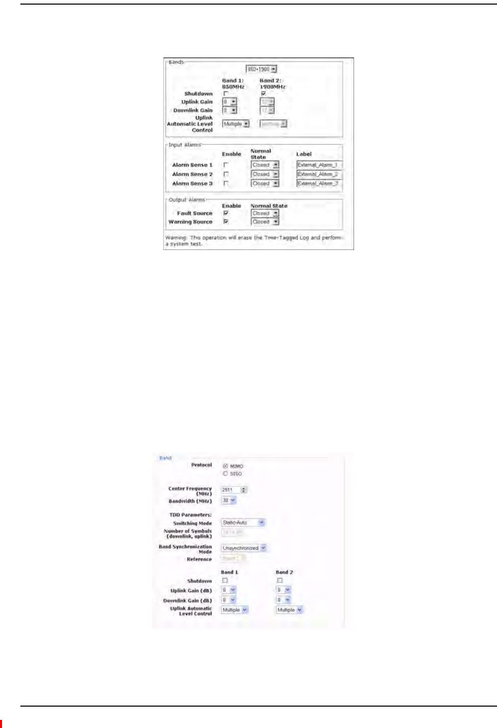
12 IntheBandspanel,dothefollowing:
•Youshouldnothavetoselectthebands.Thesystemselfconfiguresthebandbyvalidating
thatalltheRAUsconnectedarethesametype.
•Whenbothbandsarenotconfigured,usetheShutdowncheckbox.Thesystemwillignore
anyalarmsgeneratedfromtheshutdownbands.
•UsetheUplinkandDownlinkmenustoselectthegainforeachband.Youcansetsystem
gainwithinthespecifiedrangein1dBincrements.
•UsetheUplinkAutomaticLevelControlmenutoselecteitherSingleorMultiple(default)
foreachbandinthesystem.
13 FORWiMAXINSTALLATIONSONLY:Usethescrollbarontheleftsideofthepagetoscroll
downtoviewthenextpartofthewindowsshownbelow.

Configuring the Fusion Wideband System
InterReach Fusion Wideband Installation, Operation, and Reference Manual Page 143
D-620616-0-20 Rev H • TECP-77-044 Issue 7 • May 2013 © 2013 TE Connectivity Ltd.
IntheBandarea,dothefollowing:
•SelecttheProtocolmode:ThisconfiguresthesystemtosupportWiMAXradiosthatare
oneofthefollowing:
MIMO(multiplein‐multipleout)
SISO(singlein‐singleout).Thedefaultis“MIMO”.
•SelecttheCenterFrequencyandBandwidthusingthearrowsnexttothefields.Thecenter
frequencyisthefrequencyofWiMAXradiosbeingusedforBand1andBand2.
NOTE: InMIMOmode,thefrequenciesarethesame.Thesystemcanbeconfiguredtosupport2‐SISO
radios,oneperband,acrossany30MHzwithintheWiMAXband.
•Usethepull‐downtoselecttheSwitchingMode.Thisindicateswhetherornotthe
downlink‐to‐uplinkframedurationisknown.Thetwooptionsareasfollows:
–Static‐Selected:Thismodespecifiesthenumberofsymbols.Usethepull‐downto
selectthesymbolinthedownlinkanduplinkportionsoftheframe.(Thedefaultis
“29,18”.)Inthismode,thesystemalwaysswitchesfromthedownlinktotheuplink
pathafterthedownlinkportionoftheframehaselapsed.
–Static‐Auto:Thismodecausesthesystemtoattempttodeterminethecorrect
switchingtime,thenenforceit.(Thedefaultis“Static‐Auto”)
•SelecttheBandSynchronizationModewiththepull‐down.Thisparametercanbe
configuredtooperateasoneofthefollowing:
–Synchronized:ThismodeisforcaseslikeMIMO,wherethetimingforbothbandsis
thesame.Inthismode,thesystemalwaysswitchesbetweenuplinkanddownlink
simultaneouslyforbothbands.
–Unsynchronized:Inthismode,thetwoWiMAXbandsswitchindependentlyfrom
eachother.(Thedefaultis“Unsynchronized”)
•Reference:SelectwhichWiMAXradiobandwillbeusedforframereference.
•Whenanybandisnotconfigured,usetheShutdowncheckbox.Thesystemignoresany
alarmsgeneratedfromtheshutdownbands.
•Usethepull‐downtospecifytheUplinkandDownlinkgainforeachband.Youcanset
systemgainwithinthespecifiedrangein1dBincrements.
•Usethepull‐downtosettheUplinkAutomaticLevelControltoeither“Single”or
“Multiple”foreachbandinthesystem.(Thedefaultis“Multiple.”)
14 Usethescrollbarontheleftsideofthewindowtoscrolldowntoviewtherestofthewindow
asshownbelow.

Installing Fusion Wideband
Page 144 InterReach Fusion Wideband Installation, Operation, and Reference Manual
© 2013 TE Connectivity Ltd D-620616-0-20 Rev H • TECP-77-044 Issue 7 • May 2013
15 IntheInput/OutputAlarmspanel,dothefollowingforeachAlarmSense:
•EnableeachAlarmSensebyusingthecheckbox.
•Usethepull‐downtosettheNormalStatetoClosedorOpened.(Thedefaultis“Closed.”
•Assignalabeltoeachalarmsense.
16 Whenyouhavecompletedinputtingthedesiredinformation,clickInstall System toconfigure
thesystem.
DuringconfigurationalldisconnectstatusesareclearedforattachedRAUs;thefrequency
band,gain,andsystemlabelareset;logsarecleared;thesystemtestisperformed;andfinally
thesystemtreeisrefreshed.Theiconsshouldbe:
Ifthereareproblems,theiconswillbedifferentandamessageisdisplayedintheMessages
pane.
17 ConnecttheMainHubtotheRFsource(forexample,BTSorBDA).
CAUTION! DonotexceedthemaximuminputRFpower(1Watt)totheFusionWidebandMainHub.
ExceedingthelimitcouldcausepermanentdamagetotheHub.
CAUTION! OnlycarriersandtheirapprovedinstallersorTE‐authorizedinstallersareallowedtoconnectto
theRFsource.Seriousdamagetotheequipmentcanoccurifitisover‐driven.
TheFusionWidebandsystemshouldnowbeoperational.Usingamobilephone,walkyour
siteandtestthesignalstrength.
18 MakesuretochangetheTCP/IPsettinginyourlaptopbacktotheiroriginalvalues.
NOTE: TEequipmentisdesignedtooperateinthelicensedfrequencybandsofmobileoperators.Inthe
USA,theEU,andmostcountriesthisequipmentmayonlybeusedbythelicensee,hisauthorized
agentsorthosewithwrittenauthorizationtodoso.Similarly,unauthorizeduseisillegal,and
subjectstheownertothecorrespondinglegalsanctionsofthenationaljurisdictioninvolved.
OwnershipofTEequipmentcarriesnoautomaticrightofuse.
Indicates that the band is correctly set on the Main Hub.
Indicates that the band is correctly set on the Expansion Hub.
Indicates that communications are OK.

Splicing Fiber Optic Cable
InterReach Fusion Wideband Installation, Operation, and Reference Manual Page 145
D-620616-0-20 Rev H • TECP-77-044 Issue 7 • May 2013 © 2013 TE Connectivity Ltd.
SPLICINGFIBEROPTICCABLE
ThefibercablemusthaveSC/APCconnectorsfortheentirerun.Ifitdoesnot,youcansplicea
pigtail,whichhasSC/APCconnectors,tothefibercable.
TEofferstwopigtails:oneforsingle‐modefiber(PN4013SCAPC‐3)andoneformulti‐modefiber
(PN4012SCAPC‐3).
TErecommendsFusionWidebandsplicesbecausetheyhavethelowestsplicelossandreturn
loss.MechanicalspliceshavehigherlossesandhigherbackreflectionthanFusionWideband
splicesandarenotrecommended.
UsingaFusionWidebandsplicerinvolvesfusingtogethertwobuttedandcleavedendsoffiber.
TheFusionWidebandspliceralignsthefibersandmaintainsalignmentduringtheFusion
Widebandprocess.FusionWidebandspliceshaveverylowloss(typicallylessthan0.05dB)and
verylowbackreflection(returnloss).FusionWidebandsplicesshouldbeorganizedinasplice
traydesignedtostoreandprotectthesplices.
NOTE: Thefollowingproceduresassumethatthesystemisnewfromthefactoryandthatithasnot
beenprogrammedwithbands.Ifyouarereplacingcomponentsinapre‐installedsystemwith
eithernewunitsorunitsthatmayalreadybeprogrammed(forexample,re‐usingunitsfrom
anothersystem),referto“ReplacingFusionWidebandComponents”onpage175.
OptionA:FusionWidebandSplicetheFiber‐OpticCabletotheSC/APCPigtail
1MakesuretheFusionWidebandsplicerissettothepropermode(thatis,single‐or
multi‐mode).
2SecureboththefibercableandtheSC/APCpigtailinasplicetraythatisinstalledimmediately
adjacenttotheHub.
3Preparethefiberendbycuttingbackthepolyethylenejacket,thekevlarorfiberglassstrength
members,theextrudedcoating,andthebuffercoatinginordertoexposethe“barefiber”–
claddingpluscore.
4EnsurethatsufficientslackismaintainedinordertobeabletoreachtheFusionWideband
splicer.
5Cleantheuncladfibercoreusingisopropylalcoholandlint‐freewipes.
6CleavetheuncladfibertothelengthprescribedbytheFusionWidebandsplicer’s
specificationsheets.
7RepeatStep4throughStep6fortheSC/APCpigtail.
8Passthesplicesleeveontothefiberstrand.
9PositionbothfiberendsintheFusionWidebandsplicerandcompletespliceinaccordance
withtheFusionWidebandsplicer’soperationinstructions.
10 EnsurethattheestimatedlossforthespliceasmeasuredbytheFusionWidebandspliceris
0.10dBorbetter.
11 SlidetheFusionWidebandsplicingsleeveoverthepointoftheFusionWidebandsplice.
FusionWidebandSplicingofFiberandPigtail

Installing Fusion Wideband
Page 146 InterReach Fusion Wideband Installation, Operation, and Reference Manual
© 2013 TE Connectivity Ltd D-620616-0-20 Rev H • TECP-77-044 Issue 7 • May 2013
12 PlacethesleeveandfusedfiberintotheFusionWidebandsplicer’sheater.
13 Allowtimeforthesplicesleevetocure.
14 Returnfibersplicetothesplicetray,storethesleeveinaspliceholderwithinthetray,and
storeexcesscablelengthinaccordancewiththetraymanufacture’sdirections.
15 Aftersuccessfullytestingthefiber,plugtheSC/APCpigtailintotheproperopticalportonthe
Hub.
OptionB:FusionWidebandSplicetheFiber‐OpticCabletotheSC/APCPigtail
1MakesuretheFusionWidebandsplicerissettothepropermode(thatis,single‐or
multi‐mode).
2SecureboththefibercableandtheSC/APCpigtailinasplicetrayportionofafiber
distributionpanel.
3Preparethefiberendbycuttingbackthepolyethylenejacket,thekevlarorfiberglassstrength
members,theextrudedcoating,andthebuffercoatinginordertoexposethe“barefiber”–
claddingpluscore.
4EnsurethatsufficientslackismaintainedinordertobeabletoreachtheFusionWideband
splicer.
5Cleantheuncladfibercoreusingisopropylalcoholandlint‐freewipes.
6CleavetheuncladfibertothelengthprescribedbytheFusionWidebandsplicer’s
specificationsheets.
7RepeatStep3throughStep6fortheSC/APCpigtail.
8Passthesplicesleeveontothefiberstrand.
9PositionbothfiberendsintheFusionWidebandsplicerandcompletespliceinaccordance
withtheFusionWidebandsplicer’soperationinstructions.
10 EnsurethattheestimatedlossforthespliceasmeasuredbytheFusionWidebandspliceris
0.10dBorbetter.
11 SlidetheFusionWidebandsplicingsleeveoverthepointoftheFusionWidebandsplice.
12 PlacethesleeveandfusedfiberintotheFusionWidebandsplicer’sheater.
13 Allowtimeforthesplicesleevetocure.
14 Returnfibersplicetothesplicetray,storethesleeveinaspliceholderwithinthetray,and
storeexcesscablelengthinaccordancewiththetraymanufacture’sdirections.
15 Aftersuccessfullytestingthefibercable,plugtheSC/APCpigtailintothebacksideofthe
SC/APCbulkheadintheFiberDistributionPanel.
16 InstallaSC/APCpatchcordbetweenthefrontsideoftheSC/APCbulkheadandtheproper
opticalportontheHub.
NOTE: Forinformationontroubleshooting,see“Maintenance,Troubleshooting,andTechnical
Assistance”onpage181.

Interfacing the Fusion Wideband Main Hub to an RF Source
InterReach Fusion Wideband Installation, Operation, and Reference Manual Page 147
D-620616-0-20 Rev H • TECP-77-044 Issue 7 • May 2013 © 2013 TE Connectivity Ltd.
INTERFACINGTHEFUSIONWIDEBANDMAINHUBTOANRFSOURCE
CAUTION! OnlyTEpersonnelorTE‐authorizedinstallationpersonnelshouldconnecttheFusionWideband
MainHubtoitsBandassociatedbasestationorrepeater.Exceedingthemaximuminputpower
couldcausefailureoftheFusionWidebandMainHub(referto“RemoteAccessUnitConnectors”
onpage57formaximumpowerspecifications).Ifthemaximumcompositepoweristoohigh,
attenuationisrequired.
NOTE: Thefollowingproceduresassumethatthesystemisinstalledandhasbeenprogrammedwith
bands.
ConnectingaSingleFusionWidebandMainHubtoanRFSource
TheFusionWidebandsystemsupportsthreeRFsources,oneforBand1,Band2,andBand3.This
sectionexplainshoweachBandcanbeconnectedtoitsassociatedRFsource.
CAUTION! OnlyTEpersonnelorTE‐authorizedinstallationpersonnelshouldconnecttheFusionWideband
MainHubtoabasestationorrepeater.Exceedingthemaximuminputpowercouldcausefailure
oftheFusionWidebandMainHub(referto“RemoteAccessUnitConnectors”onpage57for
maximumpowerspecifications).Ifthemaximumcompositepoweristoohigh,attenuationis
required.
CAUTION! TheUPLINKandDOWNLINK portscannothandleaDCpowerfeedfromthebasestation.IfDC
powerispresent,aDCblockmustbeusedorthehubmaybedamaged.
ConnectingaFusionWidebandMainHubtoanIn‐BuildingBTS
Installing Fusion Wideband
Page 148 InterReach Fusion Wideband Installation, Operation, and Reference Manual
© 2013 TE Connectivity Ltd D-620616-0-20 Rev H • TECP-77-044 Issue 7 • May 2013
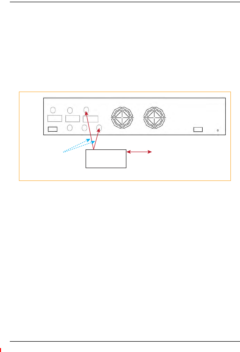
ConnectingaSimplexBaseStationtoaFusionWidebandMainHubRFBand
1ConnectanN‐maletoN‐malecoaxialcabletothetransmitsimplexconnectoronthebase
station.
2ConnecttheotherendoftheN‐maletoN‐malecoaxialcabletotheDOWNLINKconnectoronthe
HubforthecorrespondingBand1,Band2,orBand3.
3ConnectanN‐maletoN‐malecoaxialcabletothereceivesimplexconnectoronthebase
station.
4ConnecttheotherendoftheN‐maletoN‐malecoaxialcabletotheUPLINKconnectoronthe
HubforthecorrespondingBand1,Band2,orBand3.
Figure40.Simplex Base Station to a Fusion Wideband Main Hub
Simplex
Base Station
Band 3
Band 1 Band 2 Band 3
UL1 UL2 UL3
Alarms
DL1 DL2 DL3
AC Power
N-male to N-male
coaxial cable
T1/E1 to
Mobile
Switching
Center
Insert attenuator
(if needed)
NOTE: This applies to Band 1, Band 2, and Band 3.
Interfacing the Fusion Wideband Main Hub to an RF Source
InterReach Fusion Wideband Installation, Operation, and Reference Manual Page 149
D-620616-0-20 Rev H • TECP-77-044 Issue 7 • May 2013 © 2013 TE Connectivity Ltd.
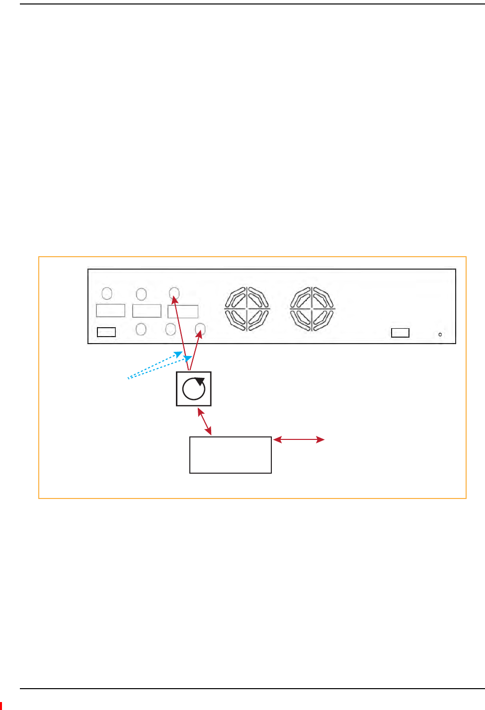
ConnectingaDuplexBaseStationtoaFusionWidebandMainHub
NOTE: Whenconnectingtoaduplexbasestation,useacirculatororduplexerbetweenitandtheFusion
WidebandMainHub.
NOTE: YoucaninsertattenuatorsbetweenthecirculatororduplexerandHubasneeded.
1ConnectanN‐maletoN‐malecoaxialcabletotheduplexconnectoronthebasestation.
2ConnecttheotherN‐maleconnectororduplexertoacirculator.
3ConnectanN‐maletoN‐malecoaxialcabletotheDOWNLINKconnectorontheHubforBand1,
Band2,andBand3.
4ConnecttheotherendoftheN‐malecoaxialcabletothetransmitconnectoronthecirculator.
5ConnectanN‐maletoN‐malecoaxialcabletotheUPLINKconnectorontheHubforBand1,
Band2,andBand3.
6ConnecttheotherendoftheN‐malecoaxialcabletothereceive connector onthecirculator.
Figure41.Duplex Base Station to a Fusion Wideband Main Hub
Duplex
Base Station
Band 1 Band 2 Band 3
UL1 UL2 UL3
Alarms
DL1 DL2 DL3
AC Power
N-male to N-male
coaxial cable
T1/E1 to
Mobile
Switching
Center
Insert attenuator
(if needed)
NOTE: This applies to Band 1, Band 2, and Band 3.
Circulator
N-male to N-male
coaxial cable
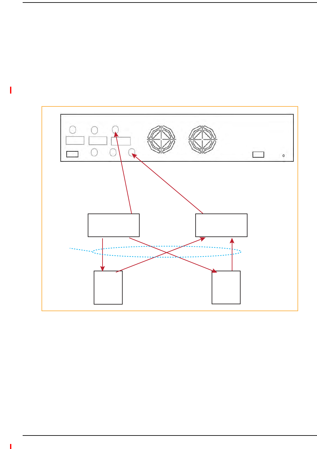
Installing Fusion Wideband
Page 150 InterReach Fusion Wideband Installation, Operation, and Reference Manual
© 2013 TE Connectivity Ltd D-620616-0-20 Rev H • TECP-77-044 Issue 7 • May 2013
CAUTION! OnlyTEpersonnelorTE‐authorizedinstallationpersonnelshouldconnecttheFusionWideband
MainHubtoabasestationorrepeater.Exceedingthemaximuminputpowercouldcausefailure
oftheFusionWidebandMainHub(referto“RemoteAccessUnitConnectors”onpage57for
maximumpowerspecifications).Ifthemaximumcompositepoweristoohigh,attenuationis
required.
Youcanusepowercombiner/splitterstoconnectaFusionWidebandMainHubRFBandto
multiplebasestations,asshowninFigure42onpage150.
Figure42.Connecting a Fusion Wideband Main Hub to Multiple Base Stations
ConnectingaFusionWidebandMainHubRFBandtoMultipleBTSs
Band 1 Band 2 Band 3
UL1 UL2 UL3
Alarms
DL1 DL2 DL3
AC Power
Insert attenuators
(if needed)
2 x 1 Power
Combiner/Splitter
N-male to N-male
coaxial-jumper cables
between Combiner/Splitter and
Fusion Main Hub’s Uplink Port
for each on Band 1, Band 2, or Band 3
2 x 1 Power
Combiner/Splitter
N-male to N-male
coaxial-jumper cables
between Combiner/Splitter and
Fusion Main Hub’s Downlink Port
for either Band 1, Band 2, or Band 3
BTS 1
UL DL
BTS 2
UL DL
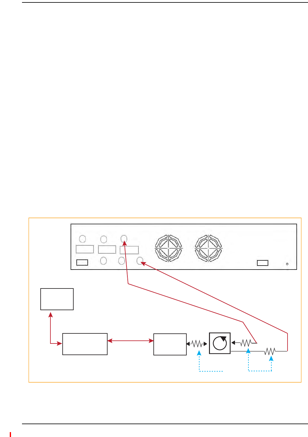
Interfacing the Fusion Wideband Main Hub to an RF Source
InterReach Fusion Wideband Installation, Operation, and Reference Manual Page 151
D-620616-0-20 Rev H • TECP-77-044 Issue 7 • May 2013 © 2013 TE Connectivity Ltd.
CAUTION! TErecommendsthatyouusealightningarrestororsurgeprotectorinaroof‐topantenna
configuration.Insertthelightningarrestororsurgeprotectorbetweentheroof‐topantennaand
therepeaterconnectedtotheFusionWidebandMainHubRFBand.
1ConnectanN‐maletoN‐malecoaxialcabletotheroof‐topantenna.
2ConnecttheotherendoftheN‐maletoN‐malecoaxialcabletothegroundedsurge
suppressor.
3ConnectanN‐maletoN‐malecoaxialcabletothegroundedsurgesuppressor.
4ConnecttheotherendoftheN‐maletoN‐malecoaxialcabletotherepeater.
5ConnectanN‐maletoN‐malecoaxialcabletotherepeater.
6ConnecttheotherendoftheN‐maletoN‐malecoaxialcabletothecirculator1connector.
7ConnectanN‐maletoN‐malecoaxialcabletothecirculator2connector.
8ConnecttheotherendoftheN‐maletoN‐malecoaxialcabletotheDOWNLINKconnectoronthe
HubforeitherBand1,Band2,orBand3.(Attenuationmayberequiredtoachievethedesired
RFoutputattheRAU.)
9ConnectanN‐maletoN‐malecoaxialcabletothecirculator3connector.
10 ConnecttheotherendoftheN‐maletoN‐malecoaxialcabletotheUPLINKconnectoronthe
HubforeitherBand1,Band2,orBand3.
Figure43.Connecting a Fusion Wideband Main Hub to a Roof-top Antenna
ConnectingaFusionWidebandMainHubtoaRoof‐TopAntenna
Band 1 Band 2 Band 3
UL1 UL2 UL3
Alarms
DL1 DL2 DL3
AC Power
Attenuator
(optional)
NOTE: This applies to Band 1, Band 2, and Band 3.
N-male to N-male
coaxial cable
Rooftop
Antenna
N-male to N-male
coaxial cable
Grounded
Surge Suppressor
Rooftop
Antenna
Circulator
12

Installing Fusion Wideband
Page 152 InterReach Fusion Wideband Installation, Operation, and Reference Manual
© 2013 TE Connectivity Ltd D-620616-0-20 Rev H • TECP-77-044 Issue 7 • May 2013
RefertotheFlexWaveFocusmanualforinformation.
ConnectingMultipleFusionWidebandMainHubstoanRFSource
Youcanusepowercombiner/splittersassplitterstoconnectmultipleFusionWidebandMain
HubsinordertoincreasethetotalnumberofRAUsinasystem.Youcanalsousepower
combiner/splitterstocombinebasestationchannelsinordertoincreasethenumberofRF
carriersthesystemtransports.
CAUTION! OnlyTEpersonnelorTE‐authorizedinstallationpersonnelshouldconnecttheFusionWideband
MainHubtoabasestationorrepeater.Exceedingthemaximuminputpowercouldcausefailure
oftheFusionWidebandMainHub(referto“RemoteAccessUnitConnectors”onpage57for
maximumpowerspecifications).Ifthemaximumcompositepoweristoohigh,attenuationis
required.
1Makesureyouhavethefollowingcomponents:
2Connectthepowercombiner/splitterstotherepeaterorbasestationusingN‐maletoN‐male
coaxialjumpercables:
aFromthefirstpowercombiner/splittertotherepeaterorbasestationUPLINK
bFromthesecondpowercombiner/splittertotherepeaterorbasestationDOWNLINK
3Connectthepowercombiner/splitterstotheHubs:
aFromthefirstHub’sUPLINK port(Band1,Band2,orBand3)tothefirstpower
combiner/splitter
bFromthefirstHub’sDOWNLINK port(Band1,Band2,orBand3)tothesecondpower
combiner/splitter
cFromthesecondHub’sUPLINK port(Band1,Band2,orBand3)tothefirstpower
combiner/splitter
dFromthesecondHub’sDOWNLINK port(Band1,Band2,orBand3)tothesecondpower
combiner/splitter
NOTE: ConnectionsshouldnotcrossBands.Forexample,allBand1connectionsshouldbemadetothe
samehybridpowercombiner/splitterconnectedtotherepeaterBTSthatmatchestheBand1
frequency.
ConnectingaFusionWidebandMainHubtoFlexwaveFocus
ConnectingMultipleFusionWidebandMainHubstoaSimplexRepeaterorBTS
Quantity Item
2hybrid power combiner/splitters—one for uplink and one for downlink (2x1 for two Fusion Wideband Main
Hubs, 3x1 for three, 4x1 for four, and so on)
1N-male to N-male coaxial jumper cable between each power combiner/splitter and the base station
2N-male to N-male coaxial jumper cables between each power combiner/splitter and each Fusion Wideband
Main Hub RF Band (either Band 1 or Band 2)
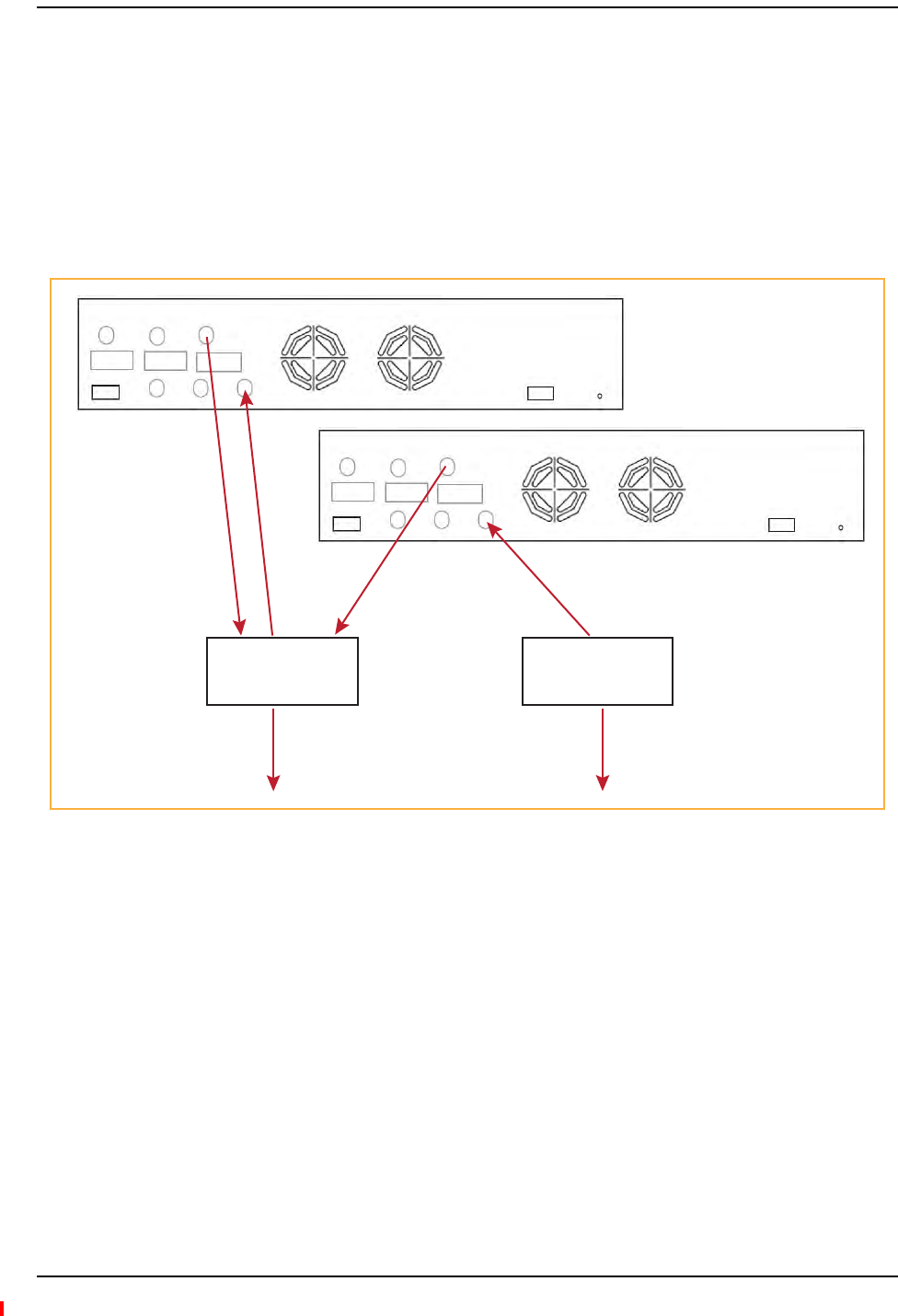
Interfacing the Fusion Wideband Main Hub to an RF Source
InterReach Fusion Wideband Installation, Operation, and Reference Manual Page 153
D-620616-0-20 Rev H • TECP-77-044 Issue 7 • May 2013 © 2013 TE Connectivity Ltd.
4CheckHubLEDs—AfterconnectingandpoweringontheHub,checkallLEDstoensurethat
thesystemisoperatingproperly.
5MakesuretheHubisgrounded.Thewarrantydoesnotcoverdamagecausedwhenan
ungroundedHubispoweredon.
NOTE: Usea50ohmterminatoronanyunusedpowercombiner/splitterports.
Figure44showshowtoconnecttwoMainHubstoasimplexrepeaterorbasestation.Connecting
twoHubsincreasesthetotalnumberofsupportableRAUsfrom8to16.
Figure44.Connecting Two Fusion Wideband Main Hub’s RF Band Ports to a Simplex Repeater or Base Station
Band 1 Band 2 Band 3
UL1 UL2 UL3
Alarms
DL1 DL2 DL3
AC Power
N-male to N-male
coaxial-jumper cables
between Combiner/Splitter
and Fusion Main Hub’s
Uplink Port for either Band 1,
Band 2, or Band 3
2 x 1 Power
Combiner/Splitter
2 x 1 Power
Combiner/Splitter
N-male to N-male
coaxial-jumper cables
between Combiner/Splitter and
Fusion Main Hub’s Downlink Port
for either Band 1, Band 2, or Band 3
Band 1 Band 2 Band 3
UL1 UL2 UL3
Alarms
DL1 DL2 DL3
AC Power
N-male to N-male
coaxial-jumper cable
to Repeater or
Base Station
N-male to N-male
coaxial-jumper cable
to Repeater or
Base Station

Installing Fusion Wideband
Page 154 InterReach Fusion Wideband Installation, Operation, and Reference Manual
© 2013 TE Connectivity Ltd D-620616-0-20 Rev H • TECP-77-044 Issue 7 • May 2013
CAUTION! OnlyTEpersonnelorTE‐authorizedinstallationpersonnelshouldconnecttheFusionWideband
MainHubtoabasestationorrepeater.Exceedingthemaximuminputpowercouldcausefailure
oftheFusionWidebandMainHub(referto“RemoteAccessUnitConnectors”onpage57for
maximumpowerspecifications).Ifthemaximumcompositepoweristoohigh,attenuationis
required.
1Makesureyouhavethefollowingcomponents:
2ConnectthecirculatortotherepeaterorbasestationusingoneN‐maletoN‐malecoaxial
jumpercable.
3Connecteachpowercombiner/splittertothecirculatorusingoneN‐maletoN‐malecoaxial
jumpercablepercombiner/splitter.
4Connectthepowercombiner/splittertotheHubsusingN‐maletoN‐malecoaxialjumper
cable:
aFromthefirstHub’sUPLINK (Band1,Band2,orBand3)porttothefirstpower
combiner/splitter
bFromthefirstHub’sDOWNLINK (Band1,Band2,orBand3)porttothesecondpower
combiner/splitter
cFromthesecondHub’sUPLINK (Band1,Band2,orBand3)porttothefirstpower
combiner/splitter
dFromthesecondHub’sDOWNLINK (Band1,Band2,orBand3)porttothesecondpower
combiner/splitter
NOTE: ConnectionsshouldnotcrossBands.Forexample,allBand1connectionsshouldbemadetothe
samehybridpowercombiner/splitterconnectedtotherepeaterBTSthatmatchestheBand1
frequency.
5CheckHubLEDs.—AfterconnectingandpoweringontheHub,checkallLEDstoensurethat
thesystemisoperatingproperly.
6MakesuretheMainHubisgrounded.Thewarrantydoesnotcoverdamagecausedwhen
anungroundedHubispoweredon.
NOTE: Usea50ohmterminatoronanyunusedpowercombiner/splitterports.
ConnectingMultipleFusionWidebandMainHubstoaDuplexRepeaterorBTS
Quantity Item
2hybrid power combiner/splitters—one for uplink and one for downlink (2x1 for two Fusion Wideband Main
Hubs, 3x1 for three, 4x1 for four, and so on)
1N-male to N-male coaxial jumper cables to connect each Fusion Wideband Main Hub’s RF Band to the power
combiner/splitters
2circulator
1N-male to N-male coaxial jumper cable between each circulator and the repeater or base station
N-male to N-male coaxial jumper cable between each circulator and power combiner/splitter
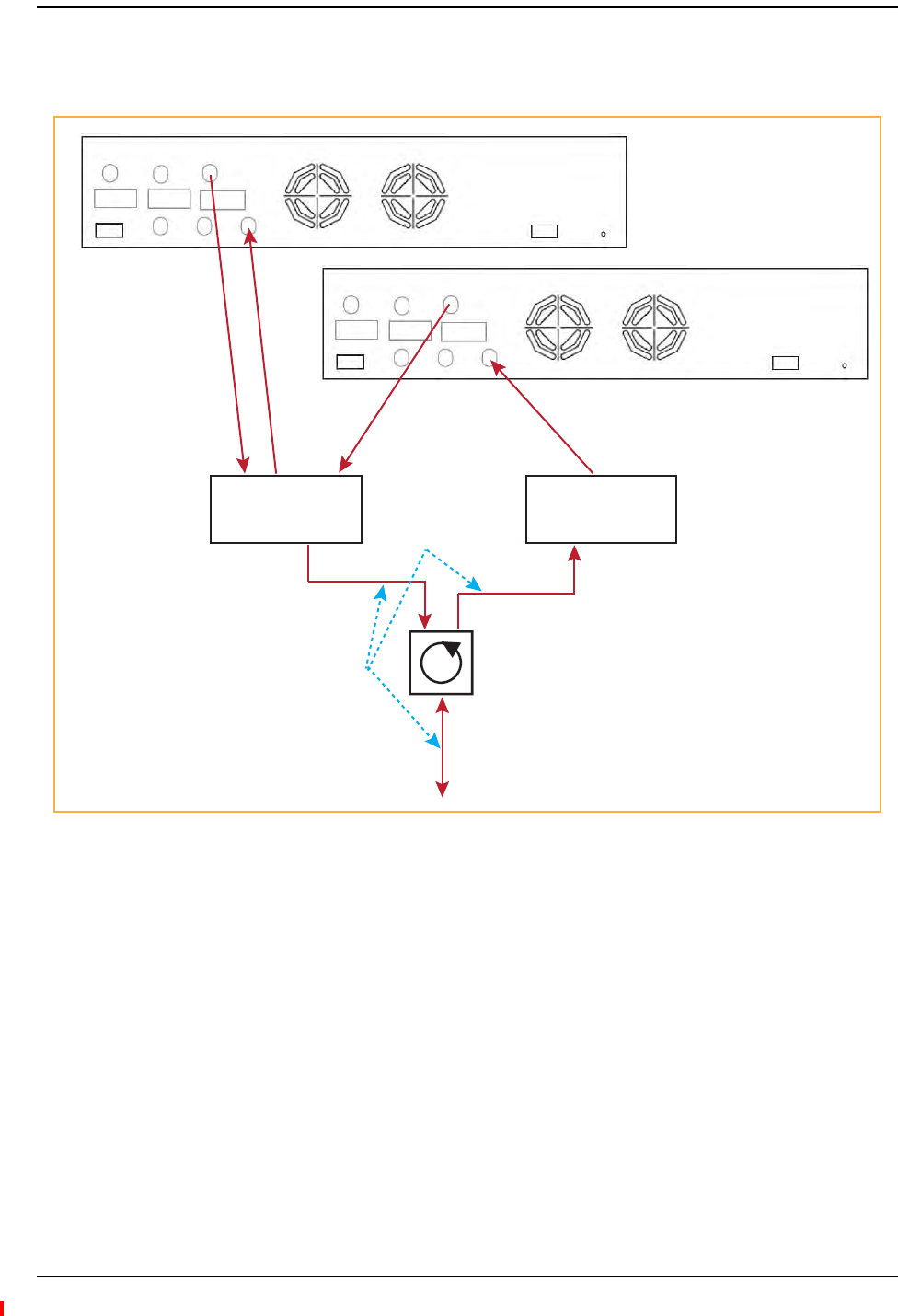
Interfacing the Fusion Wideband Main Hub to an RF Source
InterReach Fusion Wideband Installation, Operation, and Reference Manual Page 155
D-620616-0-20 Rev H • TECP-77-044 Issue 7 • May 2013 © 2013 TE Connectivity Ltd.
Figure45showshowtoconnecttwoHubstoaduplexrepeaterorbasestation.Youneedtouse
onecirculatorandonemorecoaxialjumpercable,asshown.
Figure45.Connecting Two Fusion Wideband Main Hub’s RF Band Ports to a Duplex Repeater or Base Station
Band 1 Band 2 Band 3
UL1 UL2 UL3
Alarms
DL1 DL2 DL3
AC Power
N-male to N-male
coaxial-jumper cables
between Combiner/Splitter
and Fusion Main Hub’s
Uplink Port for either Band 1,
Band 2, or Band 3
2 x 1 Power
Combiner/Splitter
2 x 1 Power
Combiner/Splitter
N-male to N-male
coaxial-jumper cables
between Combiner/Splitter and
Fusion Main Hub’s Downlink Port
for either Band 1, Band 2, or Band 3
Band 1 Band 2 Band 3
UL1 UL2 UL3
Alarms
DL1 DL2 DL3
AC Power
Circulator
Base Station
to Repeater or
N-male to N-male
coaxial-jumper cable
N-male to N-male
coaxial-jumper cable
N-male to N-male
coaxial-jumper cable
Insert attenuator
(if needed)

Installing Fusion Wideband
Page 156 InterReach Fusion Wideband Installation, Operation, and Reference Manual
© 2013 TE Connectivity Ltd D-620616-0-20 Rev H • TECP-77-044 Issue 7 • May 2013
CONNECTINGCONTACTALARMSTOAFUSIONWIDEBANDSYSTEM
TheFusionWidebandMainHubcangenerate(source)twocontactalarmsaswellassensethree
externalcontactalarm.
•AlarmSource—TheFusionWidebandMainHubhastwoalarmcontacts,fault(major)and
warning(minor).Thesecontactsarenormally‐closed(NC)andwillopenwhenaninternal
alarmisdetected.Forfurtherinformation,see“AlarmSource”onpage157.
NOTE: Thecontactcanbechangedtonormally‐open(NO)withAdminBrowser.Thisisnot
recommendedsincenoalarmwouldbesentifpowertotheFusionWidebandMainHubfails.
–Faultisactivatedwhenanyfaultsordisconnectsaredetected.
–Warningisactivatedwhenanywarningconditionsaredetectedexceptlockoutorwhen
theend‐to‐endsystemtestisnotvalid.
•AlarmSense—TheFusionWidebandMainHubcanmonitor3externalalarmcontacts.Each
portcanbeconfiguredfornormally‐open(NO)ornormally‐closed(NC)contacts.The
interfaceexpectsasetoffloatingcontacts,andanexternalvoltagesourceisnotrequiredfor
thisinterface.UseAdminBrowsertomonitortheportstatus.Forfurtherinformation,see
“A la r m S e n s e ” o n p a g e 1 6 0 .
Table90liststhealarmtypes,equipmenttowhichtheFusionWidebandMainHubisconnected,
cable(s)used,andthefaultsandwarningsthataredetected.
NotethatFlexWaveFocussupportsonlyfaults(majorerrors).
Table90.AlarmTypes
Alarm
Type
Fusion Wideband
Connected to
Cable(s) Used Errors Detected
Source FlexWave 5-port Alarm Daisy-Chain Cable Faults
Source BTS 5-port Alarm Daisy-Chain Cable Faults and Warnings
In addition, a custom daisy-chain cable-to-BTS interface cable
is required. Make this interface cable to the desired length and
with the appropriate pin placement.
Sense Unison 5-port Alarm Daisy-Chain Cable
and the Alarm Sense Adapter Cable
Faults
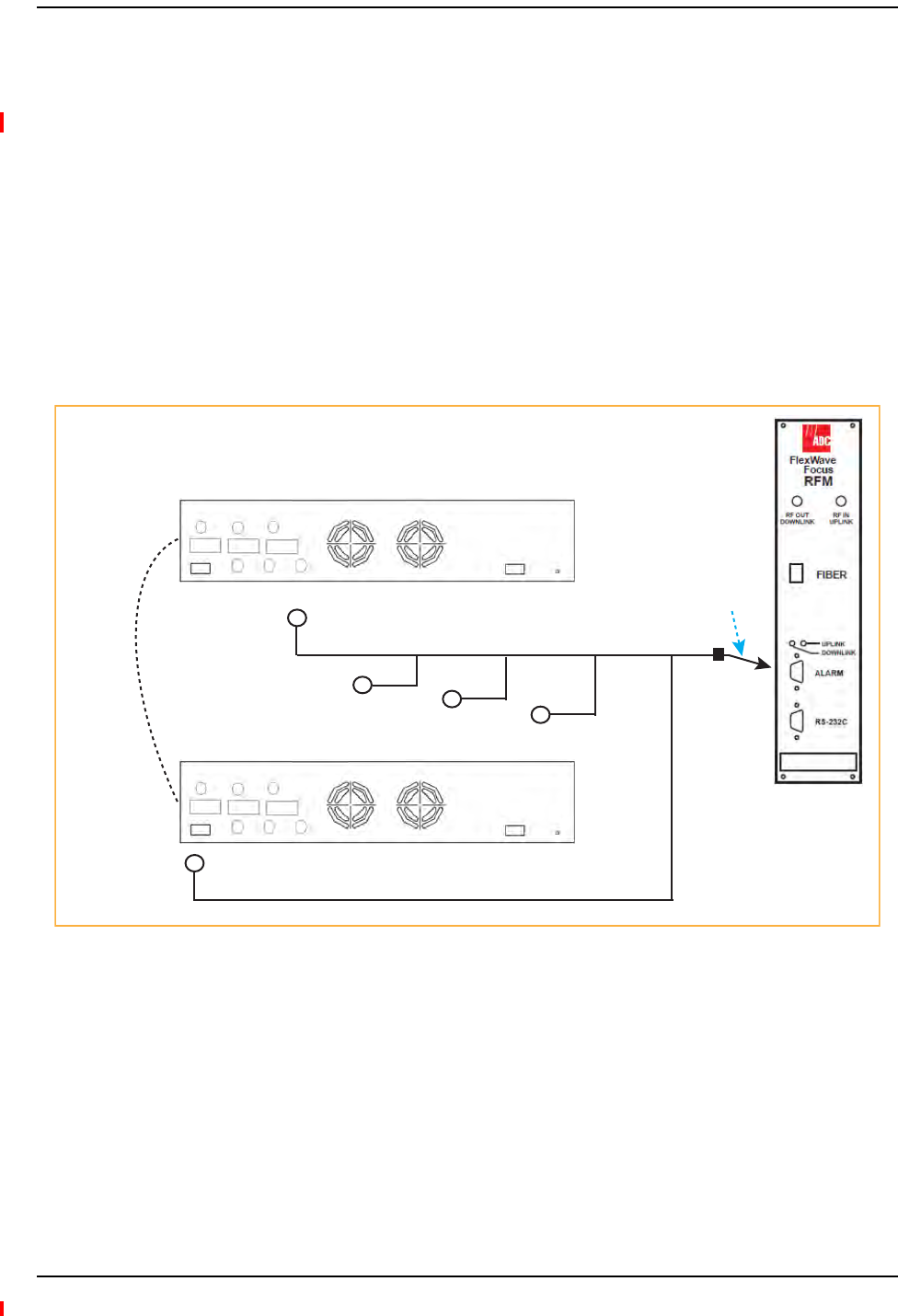
Connecting Contact Alarms to a Fusion Wideband System
InterReach Fusion Wideband Installation, Operation, and Reference Manual Page 157
D-620616-0-20 Rev H • TECP-77-044 Issue 7 • May 2013 © 2013 TE Connectivity Ltd.
AlarmSource
FusionWidebandalwaysactsasanalarmsource,nomatterwhattypeofequipmentyouare
connectingto.Referto“AlarmSense”onpage160ifyouwantFusionWidebandtosenseUnison
contactclosuresorotherexternalalarms.
NOTE: Thefollowingproceduresassumethatthesystemisinstalledandthathasbeenprogrammed
withbands.
UsingFlexWaveFocustoMonitorFusionWideband
WhenyouconnectFlexWaveFocustotheFusionWideband,theFusionWidebandMainHubis
theoutputofthealarms(alarmsource)andFocusistheinput(alarmsense),asshownin
Figure46.Focussupportsonlyfaults(majorerrors).
Figure46.Connecting FlexWave to Fusion Wideband
Band 1 Band 2 Band 3
UL1 UL2 UL3
Alarms
DL1 DL2 DL3
AC Power
Band 1 Band 2 Band 3
UL1 UL2 UL3
Alarms
DL1 DL2 DL3
AC Power
Fusion Main Hub
May need
9-pin Adapter
that ships
with the cable
Alarm
Sense
5-port Alarm Daisy-Chain Cable
Alarm
Source
Alarm
Source
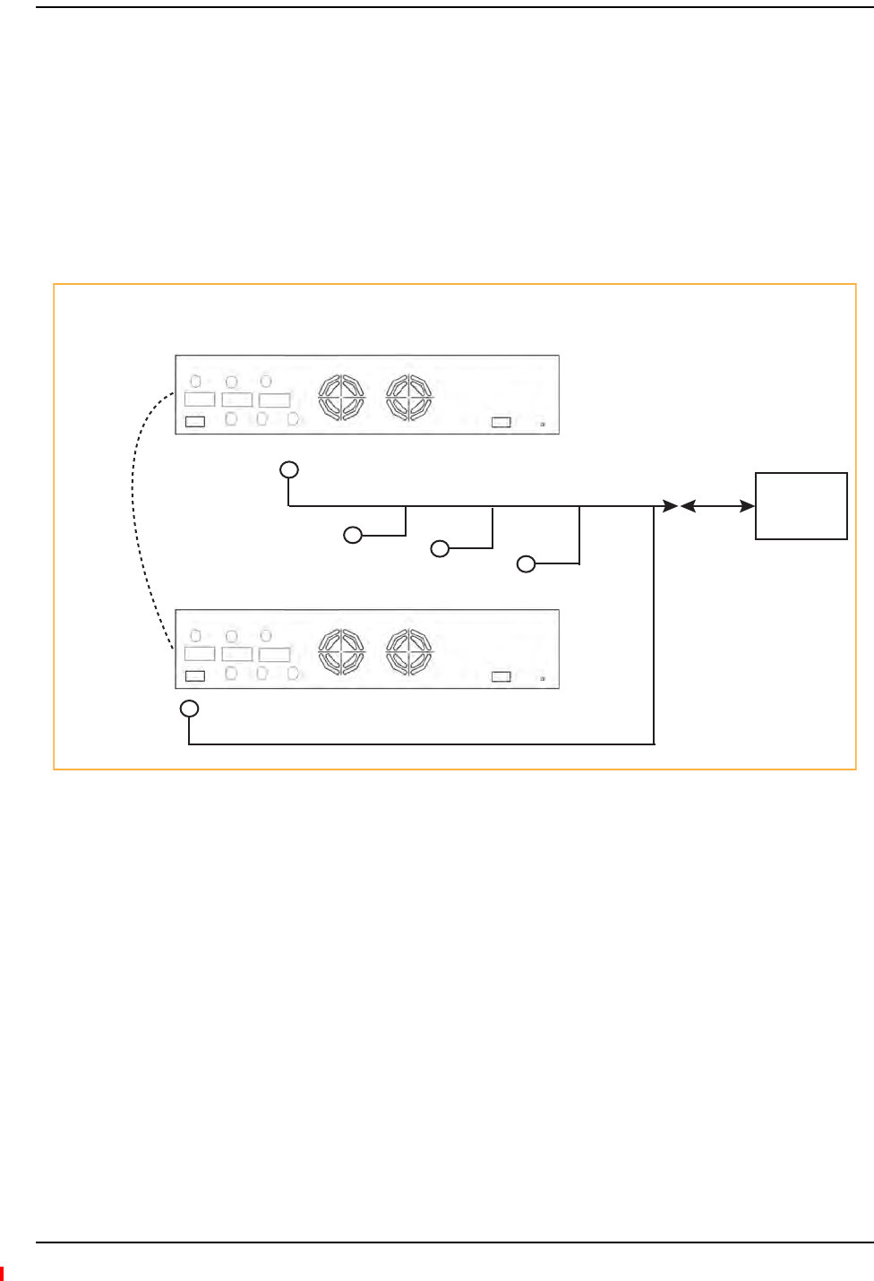
Installing Fusion Wideband
Page 158 InterReach Fusion Wideband Installation, Operation, and Reference Manual
© 2013 TE Connectivity Ltd D-620616-0-20 Rev H • TECP-77-044 Issue 7 • May 2013
UsingaBaseStationtoMonitorFusionWideband
NOTE: TheBTSmustbeconfigured,bythecarrier,forcontactclosuremonitoringpriortoconnectinga
FusionWidebandMainHubtoit.
WhenyouconnectaBTStoFusionWideband,theFusionWidebandMainHubistheoutputofthe
alarms(alarmsource)andtheBTSistheinput(alarmsense),asshowninFigure47.Aninterface
cableisrequiredbetweenthedaisy‐chaincableandtheBTS.BecauseBTSalarminterfacepinouts
andFusionWideband‐to‐BTSdistancesvary,thiscableisoftencustomandwiredon‐site.Refer
to“OpticalFiberUplink/DownlinkPorts”onpage33forAlarmContactdetails(NormallyClosed).
Figure47.Using a BTS to Monitor Fusion Wideband
NOTE: Fornormallyopencontacts,thefaultandwarningcontactsneedtobewiredinparallelwith
otherMainHubs.
NOTE: TEdoesnotrecommendusingnormallyopencontacts.
Band 1 Band 2 Band 3
UL1 UL2 UL3
Alarms
DL1 DL2 DL3
AC Power
Band 1 Band 2 Band 3
UL1 UL2 UL3
Alarms
DL1 DL2 DL3
AC Power
Fusion Main Hub
Alarm
Sense
5-port Alarm Daisy-Chain Cable
Alarm
Source
BTS
Alarm
Source Interface
Cable
(custom-made, on-site)
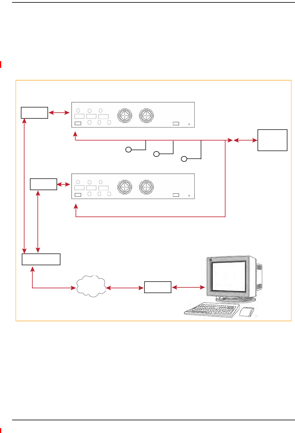
Connecting Contact Alarms to a Fusion Wideband System
InterReach Fusion Wideband Installation, Operation, and Reference Manual Page 159
D-620616-0-20 Rev H • TECP-77-044 Issue 7 • May 2013 © 2013 TE Connectivity Ltd.
UsingaBaseStationandAdminBrowsertoMonitorFusionWideband
NOTE: TheBTSmustbeconfigured,bythecarrier,forcontactclosuremonitoringpriortoconnectinga
FusionWidebandMainHubtoit.
InordertotakefulladvantageofFusionWideband’sOA&McapabilitiesyoucanuseTE
AdminBrowsersoftwareinadditiontoaBTStomonitorthesystem,asshowninFigure48.Refer
to“SNMPInterface”onpage172forSNMPoptionalfeaturecapabilities.
Figure48.Using a BTS and AdminBrowserto Monitor Fusion Wideband
Band 1 Band 2 Band 3
UL1 UL2 UL3
Alarms
DL1 DL2 DL3
AC Power
Fusion Main Hub
Alarm
Sense
5-port Alarm Daisy-Chain Cable
Alarm
Source
BTS
PSTN
Interface
Cable
(custom-made, on-site)
PC running
Standard
Browser
Software
Modem
Line Switch
Modem
Band 1 Band 2 Band 3
UL1 UL2 UL3
Alarms
DL1 DL2 DL3
AC Power
Modem
Alarm
Source
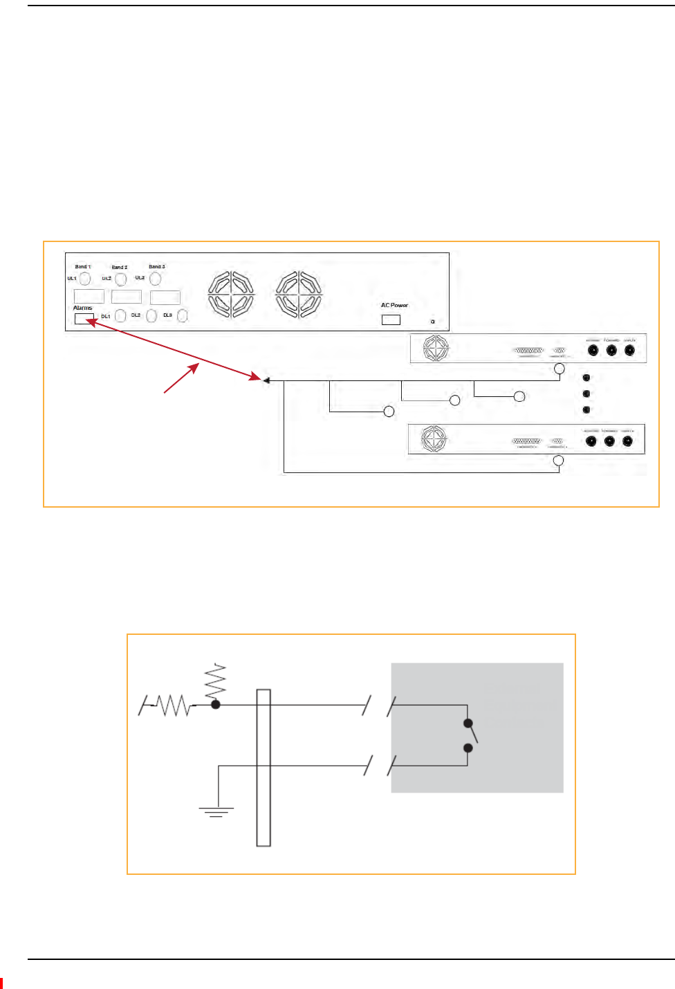
Installing Fusion Wideband
Page 160 InterReach Fusion Wideband Installation, Operation, and Reference Manual
© 2013 TE Connectivity Ltd D-620616-0-20 Rev H • TECP-77-044 Issue 7 • May 2013
AlarmSense
UseAdminBrowsertoenabletheFusionWidebandsystemfor“alarmsense”whenconnectingto
thecontactclosureofUnisonMainHubsorotherexternalalarms(refertoSetContactSense
PropertiesintheAdminBrowserUserManual).
NOTE: Thisprocedureassumesthatthesystemisinstalledandthathasbeenprogrammedwithbands.
WhenyouconnectUnisontoFusionWideband,theFusionWidebandMainHubistheinputofthe
alarms(alarmsense)andtheUnisonistheoutput(alarmsource),asshowninFigure49.The
inputalarmsenseneedstobesettonormallyclosed(NC).
Figure49.Using Fusion Wideband to Monitor Unison
Unisonsupportsonlyfaults.YoumustusetheAlarmSenseAdapterCabletointerfacethe
daisy‐chaincabletoFusionWideband.Theadaptercableisrequiredbecauseittranslatesthe
UnisonfaultpinouttothesenseinputpinsontheFusionWidebandMainHub.
Figure50.Alarm Sense Contacts
5-port Alarm Daisy-Chain Cable
Up to 5 Unison Main Hubs
Alarm
Source
Alarm
Source
Alarm
Sense
Fusion Main Hub
Alarm Sense
Adapter Cable
+5V
8
1
External
Equipment
Contacts
Diagnostic 1
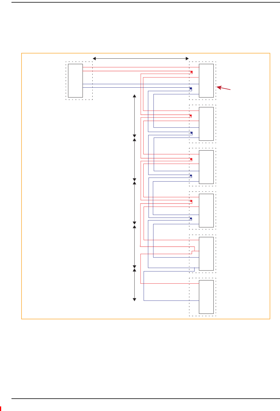
Connecting Contact Alarms to a Fusion Wideband System
InterReach Fusion Wideband Installation, Operation, and Reference Manual Page 161
D-620616-0-20 Rev H • TECP-77-044 Issue 7 • May 2013 © 2013 TE Connectivity Ltd.
AlarmCables
Figure51showsthe5‐portAlarmDaisy‐ChainCable(PN4024‐3),whichsupportsfaultand
warningconditions.
Figure51.5-port Alarm Daisy-Chain Cable
1.2 meters (4 feet)
J1
Female
J2
Male
J3
Male
J4
Male
J5
Male
J6
Male
J7
Female
Terminator
NOTE: Do not daisy-chain
Fusion Main Hubs
with FlexWave Focus
if you want both faults
and warnings from Fusion.
Only faults are reported if
you combine Fusion with
FlexWave in the same daisy
chain.
7
9
4
5
DB-9 female to
Base Station,
FlexWave Focus,
or the Alarm Sense
Adapter Cable when
connecting Unison
7
9
4
5
Splice
Splice
DB-9 male to Fusion,
Unison, FlexWave Focus,
Alarm Port
Connector
Hood
DB-9 male to Fusion,
Unison, FlexWave Focus,
Alarm Port
DB-9 male to Fusion,
Unison, FlexWave Focus,
Alarm Port
DB-9 male to Fusion,
Unison, FlexWave Focus,
Alarm Port
7
9
4
5
Splice
Splice
7
9
4
5
Splice
Splice
7
9
4
5
Splice
Splice
7
9
4
5
7
4
Option 1: DB-9 to Fusion,
Unison, FlexWave Focus
Alarm Port. J7 not used.
Option 2: Use J2-J5
for Alarm ports. Use J6 to
connect to an additional
Alarm Daisy-Chain Cable.
Do not use J7.
Option 3: Connect
fewer than 5 ports and
connect J7 to the lowest
unused port to terminate
the daisy chain.
.5 meter
(1.5 feet)
.5 meter
(1.5 feet)
.5 meter
(1.5 feet)
.5 meter
(1.5 feet)
.25 meter
(.75 feet)
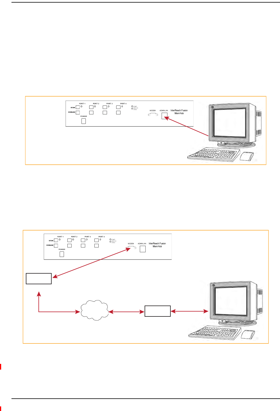
Installing Fusion Wideband
Page 162 InterReach Fusion Wideband Installation, Operation, and Reference Manual
© 2013 TE Connectivity Ltd D-620616-0-20 Rev H • TECP-77-044 Issue 7 • May 2013
ALARMMONITORINGCONNECTIVITYOPTIONS
NOTE: Thefollowingproceduresassumethatthesystemisinstalledandthathasbeenprogrammed
withbands.
DirectConnection
Inthisconfiguration,thePCconnectsdirectlytotheRJ-45 100 BASE-T portontheFusionWideband
MainHub’sfrontpanelusinganEthernetcross‐overcable.
Figure52.OA&M Direct Connection
ModemConnection
Inthisconfiguration,thePCandtheFusionWidebandMainHubconnecttoanalogmodemsand
communicateusingastandarddial‐uptelephoneconnection.
Figure53.OA&M Modem Connection
NOTE: Referto“CoaxialCable”onpage198forthemodemcablewiringinformation.
PC running
Standard
Browser
Software
Cross-over
100 BASE-T Cable
AdminBrowser is
resident in Fusion.
PSTN
PC running
Standard
Browser
Software
Modem
#140272-0
Modem
#140272-0
#4028-10
Straight-Through
Modem cable
#4028-10
Straight-Through
Modem cable
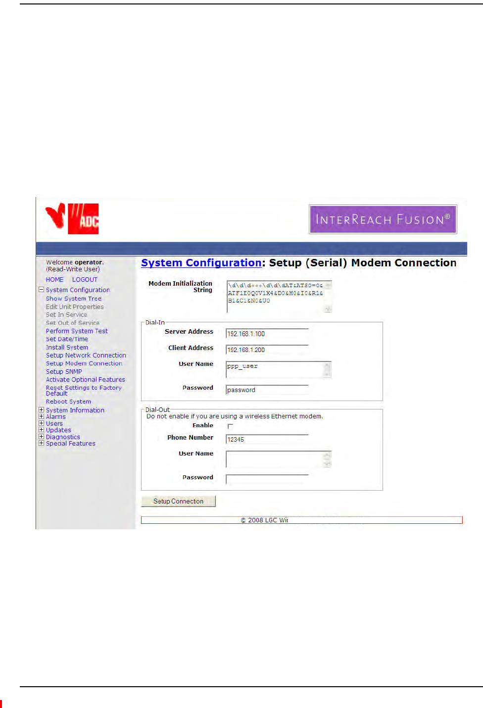
Alarm Monitoring Connectivity Options
InterReach Fusion Wideband Installation, Operation, and Reference Manual Page 163
D-620616-0-20 Rev H • TECP-77-044 Issue 7 • May 2013 © 2013 TE Connectivity Ltd.
ModemswitchsettingsareasfollowsforUSRoboticsmodem:
•PC‐side:1,2and6Up
•FusionWidebandHub‐side:2and6Up.
SettingUpFusionWidebandModem(USRModem)UsingAdminBrowser
UsethefollowingstepstosetupaPPPDial‐InonFusionWideband:
1StartAdminBrowserasexplainedintheAdminBrowsermanual.
2SelectSystemConfiguration.
3SelectSetupModemConnection.thewindowshownbelowopens:
4Makesurethemodemtypeis:None.
•ThemodeminitstringisforaUSRmodem
•TheserveraddressistheIPaddressoftheMH
5ClickSetupConnection.
TE
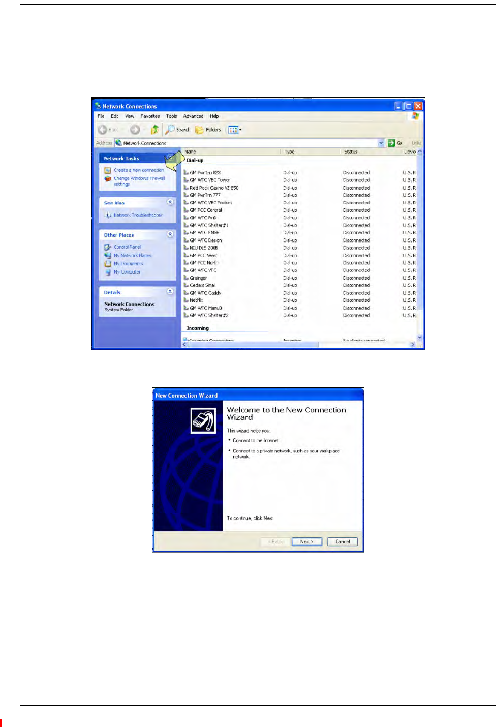
Installing Fusion Wideband
Page 164 InterReach Fusion Wideband Installation, Operation, and Reference Manual
© 2013 TE Connectivity Ltd D-620616-0-20 Rev H • TECP-77-044 Issue 7 • May 2013
SettingUpaPCModemUsingWindows
Usethefollowingsetstosetupadial‐upconnectiononyourPC.
1ClickStart,Settings,NetworkConnections.Thewindowshownbelowopens.
2ClickCreateanewconnection.Thewindowshownbelowopens.
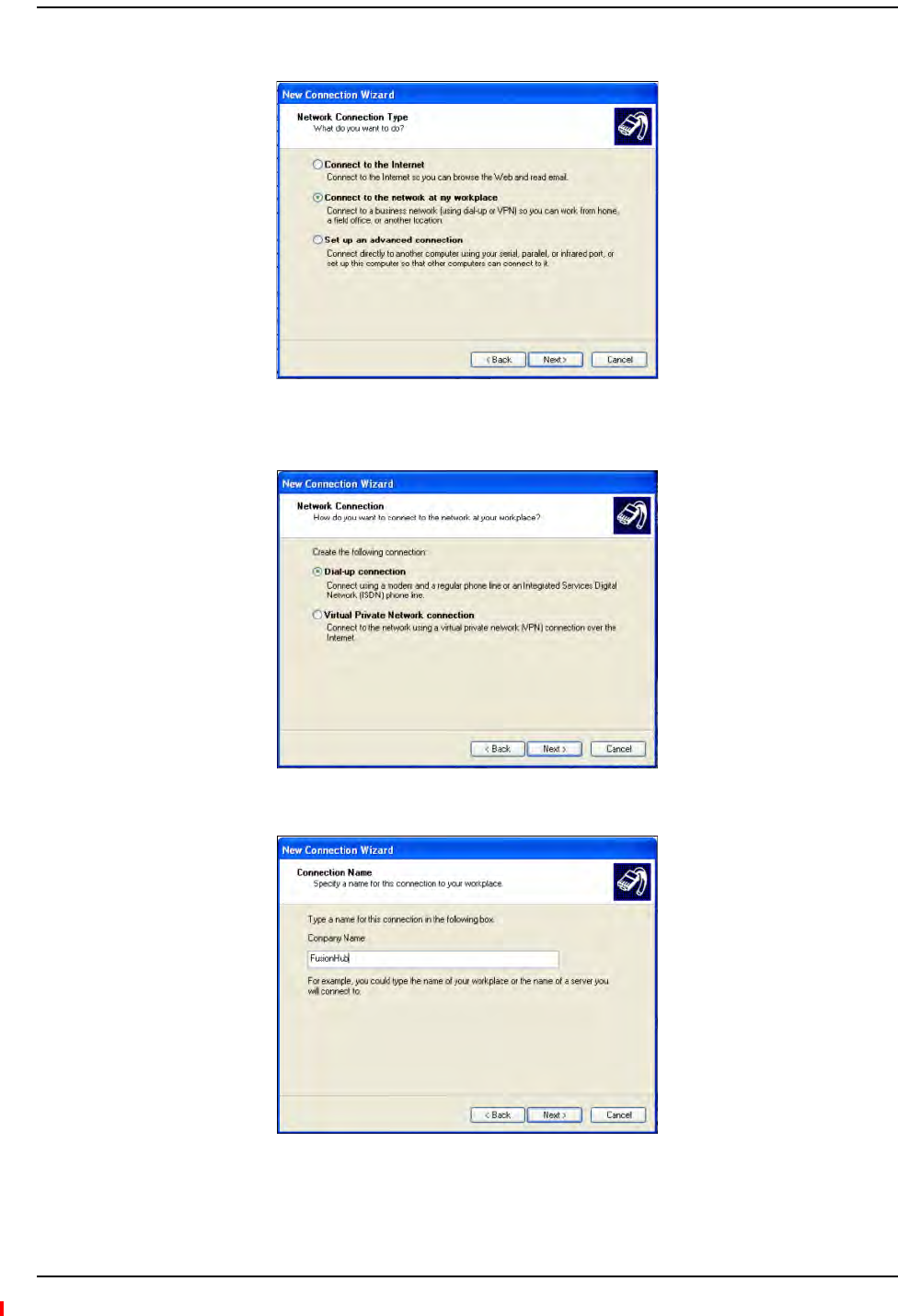
Alarm Monitoring Connectivity Options
InterReach Fusion Wideband Installation, Operation, and Reference Manual Page 165
D-620616-0-20 Rev H • TECP-77-044 Issue 7 • May 2013 © 2013 TE Connectivity Ltd.
3ClickNext.Thewindowshowninthefollowinggraphicopens.
4SelectConnecttothenetworkatmyworkplaceandclickNext;thewindowshownbelow
opens.
5SelectDial‐upconnectionandclickNext;thewindowshownbelowopens.
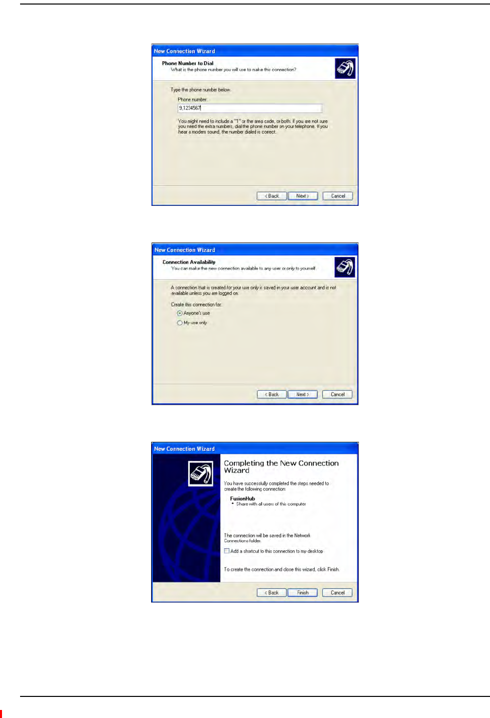
Installing Fusion Wideband
Page 166 InterReach Fusion Wideband Installation, Operation, and Reference Manual
© 2013 TE Connectivity Ltd D-620616-0-20 Rev H • TECP-77-044 Issue 7 • May 2013
6TypeanameforthisconnectionandclickNext;thewindowshownbelowopens.
7TypethedesireddialinPhonenumberandclickNext;thewindowshownbelowopens.
8SelectAnyone’suseandclickNext;thewindowshownbelowopens.
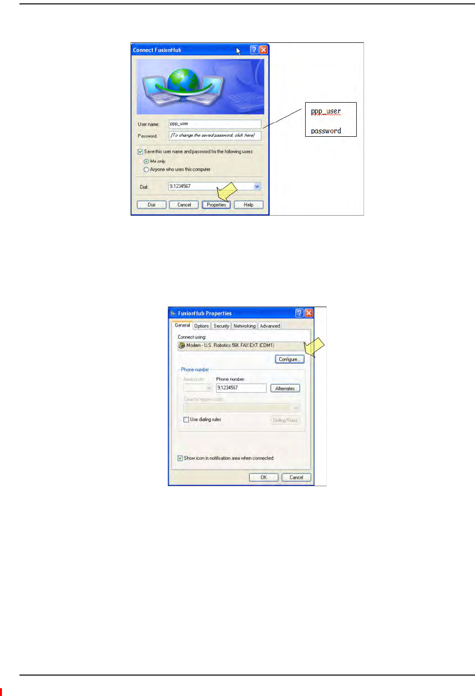
Alarm Monitoring Connectivity Options
InterReach Fusion Wideband Installation, Operation, and Reference Manual Page 167
D-620616-0-20 Rev H • TECP-77-044 Issue 7 • May 2013 © 2013 TE Connectivity Ltd.
9ClickFinish;thewindowshownbelowopens.
10 TypeapasswordasindicatedandclickProperties;thewindowshownbelowopens.
Thedefaultparametersareasfollows:
•Username:ppp_user
•Password(oneword,alllowercase):password
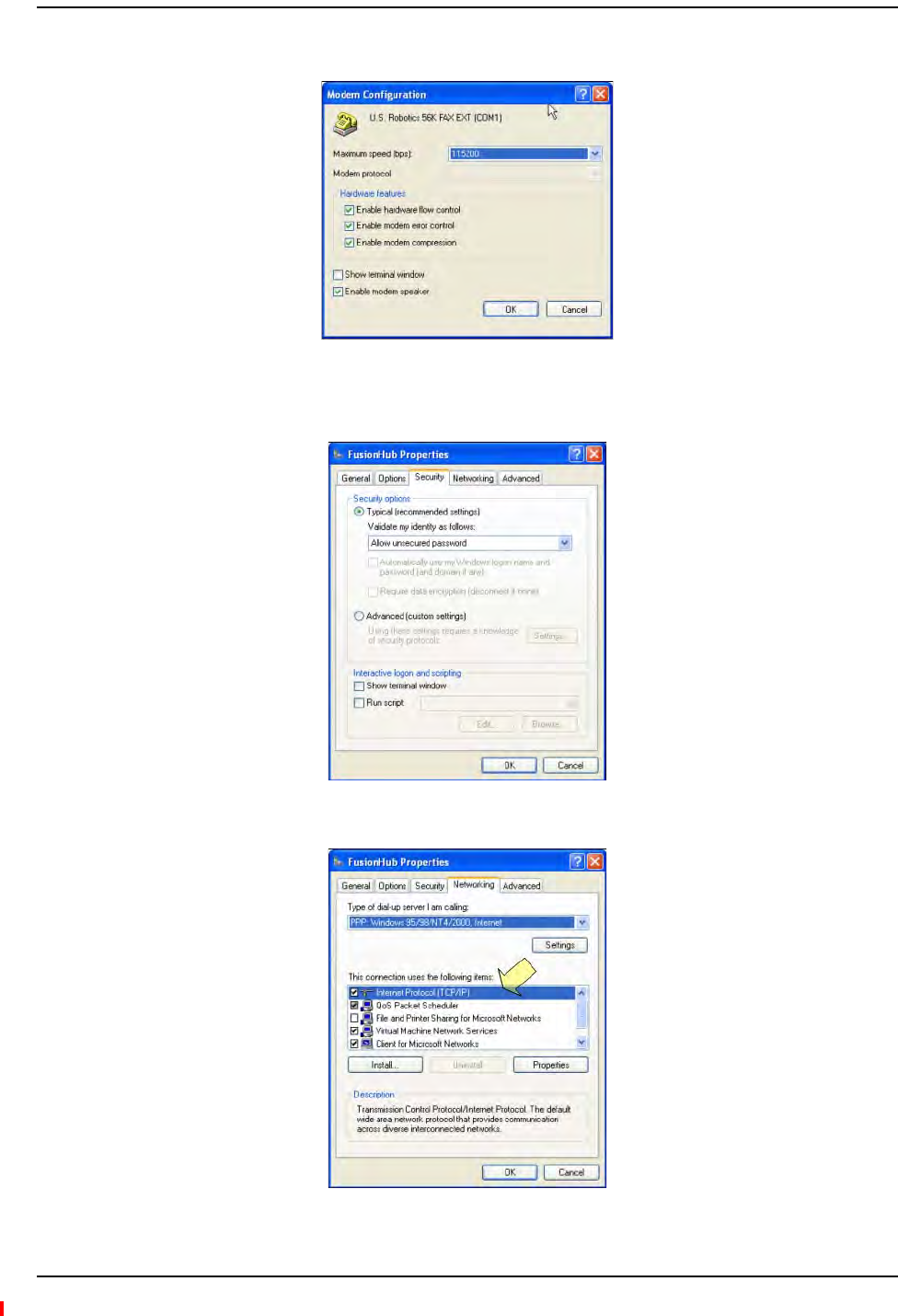
Installing Fusion Wideband
Page 168 InterReach Fusion Wideband Installation, Operation, and Reference Manual
© 2013 TE Connectivity Ltd D-620616-0-20 Rev H • TECP-77-044 Issue 7 • May 2013
11 ClickConfigure...Thewindowshownbelowopens.
12 SelectthemodemspeedandotherparametersforyourmodemasdesiredandclickOK.
13 SelecttheSecuritytab;thewindowshownbelowopens.
14 SelectTypicalandthenclicktheNetworkingtab;thewindowshownbelowopens.
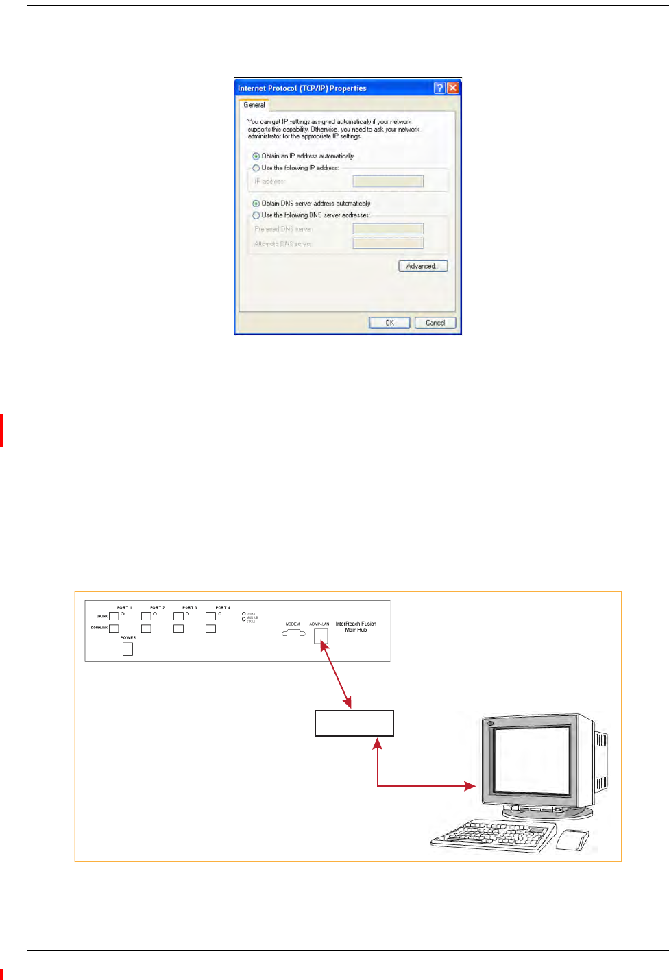
Alarm Monitoring Connectivity Options
InterReach Fusion Wideband Installation, Operation, and Reference Manual Page 169
D-620616-0-20 Rev H • TECP-77-044 Issue 7 • May 2013 © 2013 TE Connectivity Ltd.
15 SelectInternetProtocol(TCP/IP)asshownandclickProperties;thewindowshownbelow
opens.
16 SelectObtainanIPaddressautomaticallyandObtainDNSserveraddressautomatically,and
thenclickOK.
17 ToconnecttotheFusionWidebandHubovertheDial‐upconnection,startyouwebbrowser
andthenintheaddressbar,typetheserverIPaddressconfiguredin“SettingUpFusion
WidebandModem(USRModem)UsingAdminBrowser”onpage163.
100BASE‐TPortExpanderConnection
InthisconfigurationaLANswitchisusedtoallowtheconnectionofmultipledevicestoasingle
PCwitha100BASE‐Tport.TestingwasperformedwithaLinksys4‐portswitch.EachFusion
WidebandMHmusthaveauniqueIPaddress.
Figure54.OA&M Connection using a 232 Port Expander
PC running
Standard
Browser
Software
LAN Switch
100 BASE-T
Ethernet connection
AdminBrowser is
resident in Fusion.
100 BASE-T Cable
RJ-45 Male to RJ-45 Male
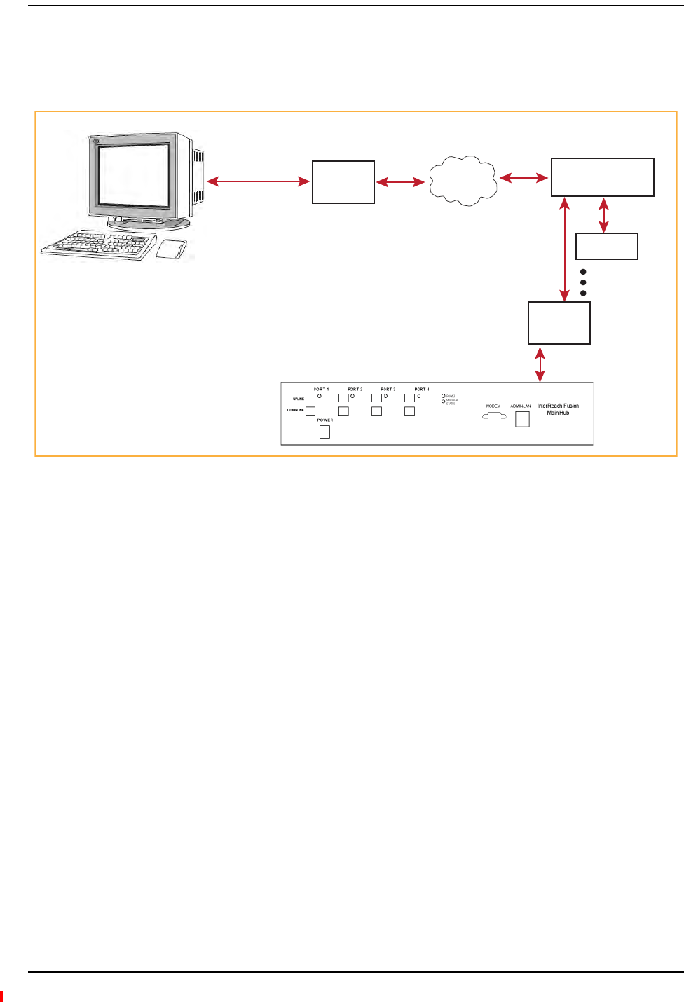
Installing Fusion Wideband
Page 170 InterReach Fusion Wideband Installation, Operation, and Reference Manual
© 2013 TE Connectivity Ltd D-620616-0-20 Rev H • TECP-77-044 Issue 7 • May 2013
POTSLineSharingSwitchConnection
Usingalinesharingswitch,youcanconnecttwoormoremodemstoasingletelephoneline.
Figure55.OA&M Connection Using a POTS Line Sharing Switch
Modem
#4028-10 Straight-Through
Modem cable
PC running
Standard
Browser
Software
PSTN
Modem
#140272-0
#4028-10
Straight-Through
Modem cable
Line Sharing Switch
4- or 8-port
4-port: #240031-0
8-port: #240052-0
Standard
phone
cable
Up to 4 modems
per switch
Modem
#140272-0
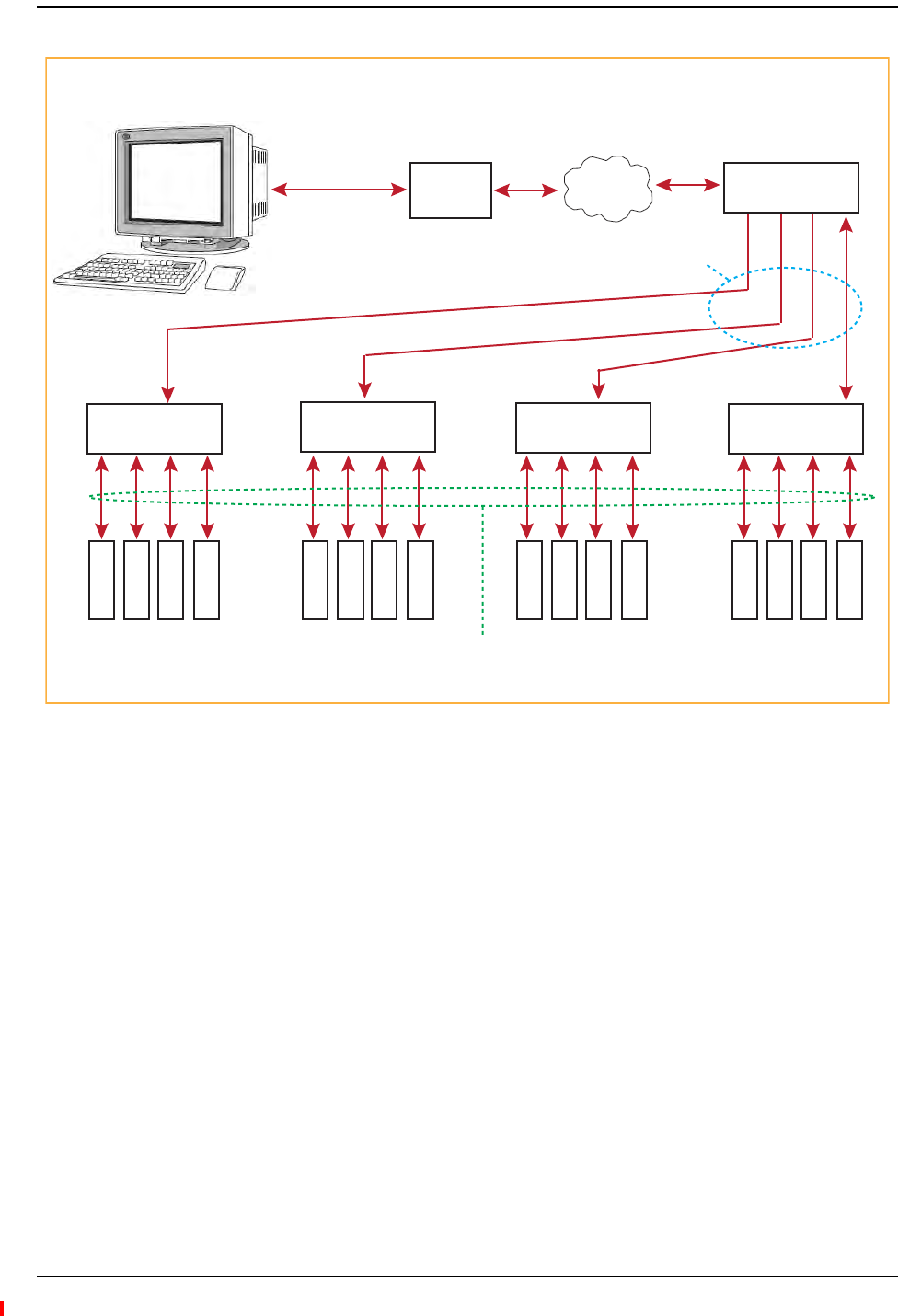
Alarm Monitoring Connectivity Options
InterReach Fusion Wideband Installation, Operation, and Reference Manual Page 171
D-620616-0-20 Rev H • TECP-77-044 Issue 7 • May 2013 © 2013 TE Connectivity Ltd.
Figure56.Cascading Line Sharing Switches
EthernetRFModem
FusionWidebandcanalsouseanEthernet‐basedRFmodem.JustaboutanyRFmodemwillwork,
althoughmodemsthatsupportPortAddressTranslationarebest.
#4028-10
Straight-Through
Modem cable
PC running
Standard
Browser
Software
PSTN
Modem
#140272-0
#4028-10
Straight-Through
Modem cable
4- or 8-Port
Line Sharing Switch
4- or 8-port
Line Sharing Switch PNs:
4-port: #240031-0
8-port: #240052-0
Standard phone cable
4- or 8-Port
Line Sharing Switch
4- or 8-Port
Line Sharing Switch
4- or 8-Port
Line Sharing Switch
4- or 8-Port
Line Sharing Switch
M
o
d
e
m
M
o
d
e
m
M
o
d
e
m
M
o
d
e
m
M
o
d
e
m
M
o
d
e
m
M
o
d
e
m
M
o
d
e
m
M
o
d
e
m
M
o
d
e
m
M
o
d
e
m
M
o
d
e
m
M
o
d
e
m
M
o
d
e
m
M
o
d
e
m
M
o
d
e
m
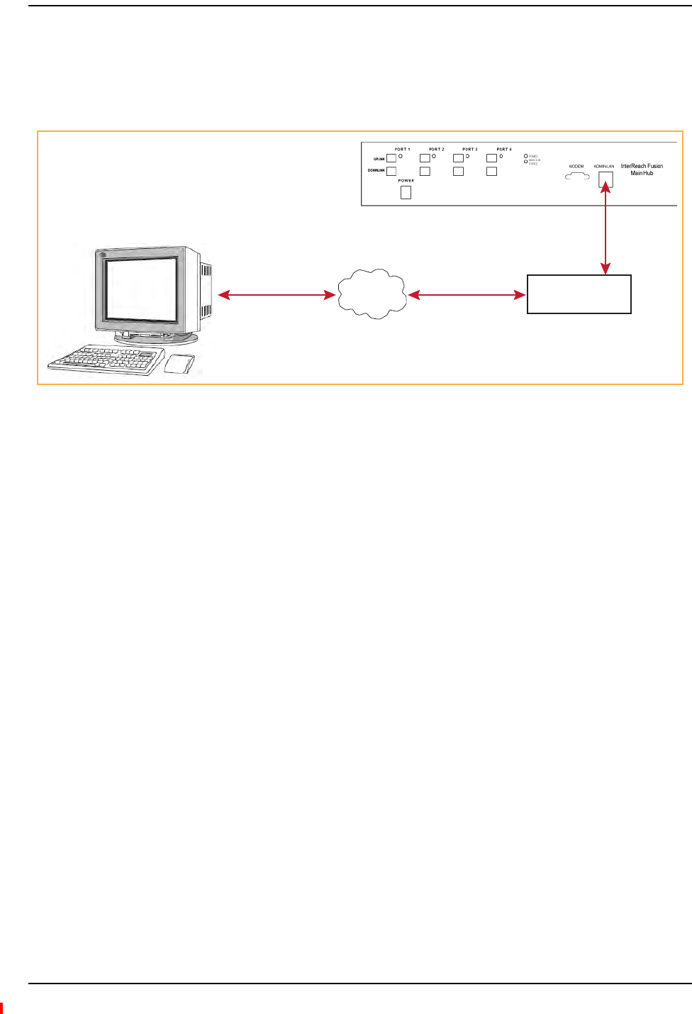
Installing Fusion Wideband
Page 172 InterReach Fusion Wideband Installation, Operation, and Reference Manual
© 2013 TE Connectivity Ltd D-620616-0-20 Rev H • TECP-77-044 Issue 7 • May 2013
EthernetLANConnection
AnEthernetLANconnectioncanbeusedtocommunicatebetweenthePCandFusionWideband.
TestingwasperformedwithanLinksys4‐portLANswitch.
Figure57.OA&M Connection Using Ethernet and ENET/232 Serial Hub
SNMPInterface
FaultsandwarningscanalsobediagnosedwithSNMPusingastandard(NMS)network
managementsystem(optional).SNMPresidentsoftwareinFusionWidebandprovidesSNMP
interactionsforTrapsandNotification.
TheFusionWidebandSNMPincludesaMIBforintegratingintotheNetworkManagementSystem
(NMS)andsupportsSNMPv1andSNMPv2c.
PC running
Standard
Browser
Software
TCP/IP LAN Switch
Ethernet Ethernet
100 BASE-T Cable
Male RJ-45 to Male RJ-45
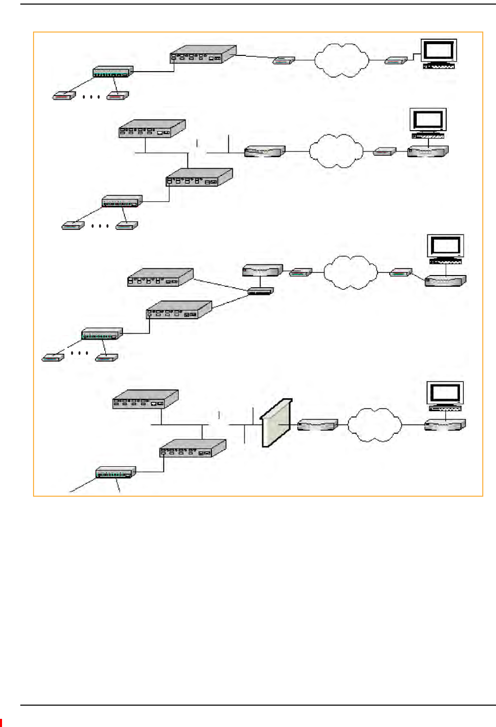
Alarm Monitoring Connectivity Options
InterReach Fusion Wideband Installation, Operation, and Reference Manual Page 173
D-620616-0-20 Rev H • TECP-77-044 Issue 7 • May 2013 © 2013 TE Connectivity Ltd.
Figure58.Fusion Wideband SNMP Configuration Options
Remote Unit Remote Unit
Expansion Hub
Expansion Hub
Main Hub
RS-232
Modem Port
PPP Modem PSTN
PPP Modem
Remote Unit Remote Unit
Expansion Hub
Main Hub
PSTN
(b) Connection to multiple systems through Dial-in router
Remote Unit Remote Unit
(c) DSL Modem through internet
(d) Connection to corporate LAN through firewall
LAN
Ethernet
Port Ethernet
Port
Dialup Router/
Firewall Modem
PPP PPP
Router
Main Hub Ethernet
Port
Ethernet
Port
Router
Switch
DSL Modem DSL Modem
Router
PSTN/
Internet
Ethernet
Port
Ethernet Port
Main Hub
LAN
Firewall
Router Router
Internet

Installing Fusion Wideband
Page 174 InterReach Fusion Wideband Installation, Operation, and Reference Manual
© 2013 TE Connectivity Ltd D-620616-0-20 Rev H • TECP-77-044 Issue 7 • May 2013

InterReach Fusion Wideband Installation, Operation, and Reference Manual Page 175
D-620616-0-20 Rev H • TECP-77-044 Issue 7 • May 2013 ©2013 TE Connectivity Ltd.
REPLACINGFUSIONWIDEBANDCOMPONENTS
ReplacinganRAU................................................................................................................................................................. 176
ReplacetheRAU .....................................................................................................................................................................176
PerformSystemTest ..............................................................................................................................................................176
ChecktheRAULEDs ...............................................................................................................................................................177
ReplacingaFusionWidebandExpansionHub ...................................................................................................................... 178
ReplaceaFusionWidebandExpansionHub...........................................................................................................................178
AdminBrowserTasks ..............................................................................................................................................................178
ChecktheExpansionHubLEDs...............................................................................................................................................178
ReplacingaFusionWidebandMainHub .............................................................................................................................. 179
ReplaceaFusionWidebandMainHub...................................................................................................................................179
ConfiguretheNewFusionWidebandMainHub....................................................................................................................179
ChecktheLEDsontheNewMainHub ...................................................................................................................................180
Topics Page

Replacing Fusion Wideband Components
Page 176 InterReach Fusion Wideband Installation, Operation, and Reference Manual
© 2013 TE Connectivity Ltd D-620616-0-20 Rev H • TECP-77-044 Issue 7 • May 2013
REPLACINGANRAU
CAUTION! ThenewRAUmustsupportthesamebandsastheoneyouarereplacing.IftheRAUisofthe
wrongbandcombination,itwillnotoperateproperlyinthesystem.
1UsingAdminBrowser,loginandclickSYSTEM INFORMATION.
2ClickSHOW SYSTEM TREE,selectFusionWidebandMainHub,andclickGET SYSTEM INFORMATION.
AllsystemsettingsforHubsandRAUswillbedisplayed.WritedownorsavetheUplinkand
DownlinkAttenuationsettingsoyoucansetthenewRAUwiththesamesettings.
3ClickCANCELtoclosethewindow.
4VerifythatthenewRAUisofthesamefrequencybandsastheonereplaced.
5DisconnecttheCATVcableandantennacablefromtheunittobereplaced.
6InstallthenewRAU.
7ConnecttheantennacableandthentheCATVcabletothenewRAU.
8ClickSYSTEM CONFIGURATION.
9ClickSHOW SYSTEM TREE.
10 SelecttheFusionWidebandRAUreplacedandclickEDIT UNIT PROPERTIES.
11 SettheattenuationofeachbandastheoldRAUwasprogrammedandclickSAVE PROPERTIES.
Whenconvenient,performSystemTesttooptimizeperformance.
CAUTION! DuringSystemTest,theentiresystemistemporarilyoff‐lineandnoRFisbeingtransmitted.
ReplacetheRAU
PerformSystemTest

Replacing an RAU
InterReach Fusion Wideband Installation, Operation, and Reference Manual Page 177
D-620616-0-20 Rev H • TECP-77-044 Issue 7 • May 2013 © 2013 TE Connectivity Ltd.
1TheRAU’sLINKandALARMLEDsshouldblink(green/red)onpowerup.
IftheLEDsdonotblinkonpowerup,replacetheRAU.
2AfterseveralsecondsbothLEDsshouldchangetogreen,whichindicatesthattheunithas
beensuccessfullyreplaced,thereiscommunicationwiththeHub,andtheRAUbandis
correct.
aIftheLINKLEDremainsgreenandtheALARMLEDremainsred,verifythattheRAUmodel
iscorrectfortheintendedfrequencyband.
Disconnectthecableandthenreconnectitonce;doingthismorethanoncewillnot
changetheresult.
bIfbothLEDsstilldon’tchangetogreen,useAdminBrowsertodeterminetheexactnature
ofthefaultandseearecommendationofhowtocorrectit.
cIfbothLEDsturnred(after90seconds),theHubhasterminatedcommunications.
ChecktheRAULEDs

Replacing Fusion Wideband Components
Page 178 InterReach Fusion Wideband Installation, Operation, and Reference Manual
© 2013 TE Connectivity Ltd D-620616-0-20 Rev H • TECP-77-044 Issue 7 • May 2013
REPLACINGAFUSIONWIDEBANDEXPANSIONHUB
1TurnoffthepowertotheExpansionHub.
2DisconnectallCATVcables,bothfibercables,andtheACpowercord.
3ReplacetheExpansionHubwithanewone.
4ConnecttheACpowercord,allCATVcables,andbothfibercables–rememberingtocleanand
correctlyconnecttheuplinkanddownlinkfiber.
5TurnonthepowertotheExpansionHub.
•TheMainHubautomaticallyissuesthebandsetting.
•Whenconvenient,useAdminBrowsertoperformSystemTestinordertooptimize
performance.
CAUTION! DuringSystemTest,theentiresystemistemporarilyoff‐lineandnoRFisbeingtransmitted.For
afullyloadedsystem(oneMainHub,fourExpansionHubs,and32RAUs),itcantakeupto90
secondstocompletethetest.
•TheLEDsshouldblinkthroughallstatesonpowerup.
–IftheLEDsdonotblinkonpowerup,replacetheExpansionHub.
–IftheLEDsdonotilluminateatall,makesuretheACpowercableisconnected.
•TheUL STATUSandDL STATUSLEDsshouldbegreen.
•TheE-HUB STATUS andPOWERLEDsshouldbegreen.
•ForeachCATVportthathasanRAUconnectedtheLEDsshouldbegreen.
ItcantakeseveralsecondsforeachCATVconnectionfortheLEDstodisplayproperly.
NOTE: Referto“TroubleshootingUsingLEDs”onpage186fortroubleshootingusingtheLEDs.
ReplaceaFusionWidebandExpansionHub
AdminBrowserTasks
ChecktheExpansionHubLEDs

Replacing a Fusion Wideband Main Hub
InterReach Fusion Wideband Installation, Operation, and Reference Manual Page 179
D-620616-0-20 Rev H • TECP-77-044 Issue 7 • May 2013 © 2013 TE Connectivity Ltd.
REPLACINGAFUSIONWIDEBANDMAINHUB
YoumustrecordthesystemconfigurationsettingsfromtheoldFusionWidebandMainHub’s
memorybeforereplacingtheunit.YouwillprogramthenewMainHubwiththisinformation.If
theMainHubisprogrammedincorrectly,thesystemwillnotwork.IftheHubtobereplacedis
notfunctioningandyoucannotuseAdminBrowser,gettheconfigurationsettingsfromthe
As‐BuiltDocumentthatwascreatedaspartoftheoriginalinstallation.
1UsingAdminBrowser,login,clickSYSTEM INFORMATION,clickSHOW SYSTEM TREE,selectFusion
WidebandHub,clickGET SYSTEM INFORMATION.
2TurnoffthepowertotheFusionWidebandMainHub.
3DisconnectallcablesandtheACpowercord.
4ReplacetheMainHubwithanewone.
5ConnecttheACpowercordandallcables.
6ConnectthecrossoverEthernetcabletothePCandthentotheMainHub’sfrontpanel
100Base‐Tconnector.ADMIN/LANport)
7StartthestandardbrowseronthePCtocommunicatewithAdminBrowsersoftware.
8TurnonthepowertotheMainHub.
9ObservetheLEDsafterturningonthepower.
AlltheLEDsblinkduringtheinitialpowerupsequence.AllLEDsshouldturngreenafterthe
poweronsequenceiscomplete.Powerupsequencetakesbetween1and2minutes
dependingonthenumberofRAUs.
CAUTION! DuringSystemTest,theentiresystemistemporarilyoff‐lineandnoRFisbeingtransmitted.
1UsingAdminBrowserandlogintotheMainHub.
2ClickSYSTEM CONFIGURATION.
3ClickSET DATE/TIMEandenterthecurrentdateandtime.
4ClickSET DATE/TIME.
5Followtheinstructionstoeventuallyrebootthesystemtosetthedateandtime.
6UsingAdminBrowser,loginandclickSYSTEM CONFIGURATION.
7ClickINSTALL SYSTEM.
8SetthenewMainHubparametersfromtheoldMainHubandclickINSTALL SYSTEM (thatis,
uplinkanddownlinkgain,systemlabels,andsoon).
9FollowtheinstructionstoperformaSystemTest.
10 ClickSYSTEM CONFIGURATIONandclickonSETUP NETWORK CONNECTION OR MODEM CONNECTIONifthe
MainHubhasNetworkorModemequipmentconnectedtoit.
ReplaceaFusionWidebandMainHub
ConfiguretheNewFusionWidebandMainHub

Replacing Fusion Wideband Components
Page 180 InterReach Fusion Wideband Installation, Operation, and Reference Manual
© 2013 TE Connectivity Ltd D-620616-0-20 Rev H • TECP-77-044 Issue 7 • May 2013
•TheLEDsshouldblinkthrougha5‐secondtestonpowerup.
–IftheLEDsdonotblinkonpowerup,replacetheMainHub.
–IftheLEDsdonotilluminateatall,makesuretheACpowercableisconnected.
•ForeachfiberopticportthathasaconnectedExpansionHub,whichhasbeenprogrammed
withaband,thePORTLEDshouldbegreen.
•Referto“TroubleshootingUsingLEDs”onpage186formoreLEDstates.
NOTE: IfthereisnocommunicationbetweentheMainHubandtheExpansionHubs,usethe
AdminBrowsertoisolatesystemproblems.
ChecktheLEDsontheNewMainHub

InterReach Fusion Wideband Installation, Operation, and Reference Manual Page 181
D-620616-0-20 Rev H • TECP-77-044 Issue 7 • May 2013 ©2013 TE Connectivity Ltd.
MAINTENANCE,TROUBLESHOOTING,ANDTECHNICAL
ASSISTANCE
Service................................................................................................................................................................................. 182
Maintenance ....................................................................................................................................................................... 183
CleaningtheFiberPorts .........................................................................................................................................................183
Considerations................................................................................................................................................................183
UsingCompressedAir.....................................................................................................................................................183
UsingIsopropylAlcohol ..................................................................................................................................................183
Troubleshooting .................................................................................................................................................................. 184
TroubleshootingUsingAdminBrowser...................................................................................................................................185
SystemTroubleshooting.................................................................................................................................................185
TroubleshootingRecommendations ..............................................................................................................................185
Fault/Warning/StatusIndications ..................................................................................................................................186
TroubleshootingUsingLEDs ...................................................................................................................................................186
TroubleshootingMainHubLEDsDuringNormalOperation ..........................................................................................186
TroubleshootingExpansionHubLEDsDuringNormalOperation ..................................................................................188
TroubleshootingCATV ......................................................................................................................................................... 189
TechnicalAssistance ............................................................................................................................................................ 190
Topics Page

Maintenance, Troubleshooting, and Technical Assistance
Page 182 InterReach Fusion Wideband Installation, Operation, and Reference Manual
© 2013 TE Connectivity Ltd D-620616-0-20 Rev H • TECP-77-044 Issue 7 • May 2013
SERVICE
Therearenouser‐serviceablepartsinanyoftheFusioncomponents.Faultyorfailedcomponents
arefullyreplaceablethroughTE.Allunitsshouldbereplacedandreturnedtothefactoryfor
serviceifneeded.
Address 541 E. Trimble Road
San Jose, California
95131-1224 USA
Help Hot Line
U.S. and Canada 1-800-530-9960
All Others +1-952-917-0761
Help Web URL http://www.te.com/WirelessSupport

Maintenance
InterReach Fusion Wideband Installation, Operation, and Reference Manual Page 183
D-620616-0-20 Rev H • TECP-77-044 Issue 7 • May 2013 © 2013 TE Connectivity Ltd.
MAINTENANCE
Keepthefiberportscleanandfreeofdust.NootherperiodicmaintenanceoftheFusion
equipmentisrequired.
CleaningtheFiberPorts
YoucancleantheHub’sfiberportsusingcannedcompressedairorisopropylalcoholandcotton
swabs.
Considerations
•Ifyouusecompressedair:
–Theairmustbefreeofdust,water,andoil.
–Holdthecanlevelduringuse.
•Ifusingisopropylalcoholandfoam‐tippedswab:
–Useonly98%pureormorealcohol.
UsingCompressedAir
1Removetheconnector’sdustcap.
2Spraythecompressedairawayfromtheunitforafewsecondstocleanoutthenozzleand
thenblowdustparticlesoutofeachfiberport.
UsingIsopropylAlcohol
1Removetheconnector’sdustcap.
2Dipa2.5mmlint‐free,foam‐tippedswabinisopropylalcoholandslowlyinsertthetipintothe
connector.
3Gentlytwisttheswabtocleantheconnector.
4Insertadryswabtodrytheconnector.
Additionally,youcanusecompressedairafterthealcoholhascompletelyevaporated.

Maintenance, Troubleshooting, and Technical Assistance
Page 184 InterReach Fusion Wideband Installation, Operation, and Reference Manual
© 2013 TE Connectivity Ltd D-620616-0-20 Rev H • TECP-77-044 Issue 7 • May 2013
TROUBLESHOOTING
NOTE: Fusionhasnouser‐serviceableparts.FaultyorfailedunitsarefullyreplaceablethroughTE;see
“Service”onpage182.
Sourcesofpotentialproblemsinclude:
•Faultycabling/connector
•MalfunctionofoneormoreFusioncomponents
•Antenna,basestation,orrepeaterproblem
•ExternalRFinterface
•Trippedcircuitbreaker
•Equipmentisnotgrounded
•UsinganEthernetcrossovercablethatdoesnotsupportfullhardwarehandshakingwhen
usingAdminBrowser
NOTE: Faultycablingisthecauseofavastmajorityofproblems.AllCATV75Ohmcableshouldbetested
toTIA‐570‐Bspecifications.TheRAUwillbedamagedifthecableconnectorisnotinstalled
properly.
YoumustuseAdminBrowserfortroubleshootingthesystem,usetheLEDsonlyasbackuporfor
confirmation.
Ifyoucannotdeterminethecauseofaproblemafterfollowingtherecommendedprocedures,call
theTECustomerSupportTeam.Forinformationonhowtocontactus,see“Service”onpage182.
Pleaseprovidethefollowinginformation:
•Serialnumberoftheunit
•Descriptionoftheproblem
•UseAdminBrowser1.00toaccessSpecialFeatures,thentheGetServiceInformationwindow.
SaveandemailthisfiletoTE.
•WhatisthelengthoftheCATVcable?Whattypeisit(forexampleRG‐6)?
•StatusoftheLEDsontheunit
•Wastheunitpowercycled?

Troubleshooting
InterReach Fusion Wideband Installation, Operation, and Reference Manual Page 185
D-620616-0-20 Rev H • TECP-77-044 Issue 7 • May 2013 © 2013 TE Connectivity Ltd.
TroubleshootingUsingAdminBrowser
UseAdminBrowsersoftwaretodeterminethecurrentfaultsandwarningsforalloftheunitsin
thesystem.Totroubleshoot,startwiththeFusionMainHub’sfaultsANDwarnings,thenproceed
toeachoftheExpansionHubs,finishingwitheachoftheRAUs.
NOTE: AdminBrowserv1.00displaysevents(faults,warnings,orstatusmessages)dependingonyour
viewpreference.Tochangeyourviewpreference,referto“ViewPreference”onpage38.
SystemTroubleshooting
UsingAdminBrowser,clickSYSTEM INFORMATION,thenclickGET FAULTS, WARNINGS AND STATUSES.This
givesthepresentstatusofthesystem,dependinguponViewPreferencesforallcomponents.
Faultsusuallyimpactservice;warningsmayimpactservice;statusmessagescontaininformation
thatshouldnotbeignored,butindicateconditionsthatdonotgenerallyimpactservice.
NOTE: Systemcommandscantakelongertoexecutecomparedtocomponentcommands.
NOTE: ThisRAUicon indicatesthereisfaultontheRAU.Thisicon indicatesadisconnected
device.Youcannotrequeststatusonadisconnecteddevice.
TroubleshootingRecommendations
Someactionsthatyoucantake,dependingonthedevicefaultorwarninginclude,areasfollows:
•HardwarefaultsonExpansionHub.
–TryswappingfiberwithanotherExpansionHubattheMainHub.
–Trycleaningthefiberandthefiberportswithalcoholfoamtipswabandcompressedair;
see“CleaningtheFiberPorts”onpage183.
–PowercycletheExpansionHub.
•UnderAlarms,click CLEAR ALL DISCONNECTSattheFusionMainHub.
•PowercycletheFusionMainHub.
•RAUhardwarefaults.TrymovingaworkingCATVtothesuspectportandverifyingthatthe
RAUcomesupOK.
•Tryisolatingthesystemcomponents:
–Checktoseeifthewholesystemiseffectedoraportionofthesystem.
–Ifthewholesystemiseffected,disconnecttheDASsystemfromtheRFsourceandseeif
theRFsourceisworking.
–Continuetoisolatebydisablingportionsofthesystem.UnderSystemConfiguration,click
SHOW SYSTEM TREEandselectacomponent.ThenclickSET OUT OF SERVICE/SET IN SERVICE.

Maintenance, Troubleshooting, and Technical Assistance
Page 186 InterReach Fusion Wideband Installation, Operation, and Reference Manual
© 2013 TE Connectivity Ltd D-620616-0-20 Rev H • TECP-77-044 Issue 7 • May 2013
Fault/Warning/StatusIndications
Oncealloftheunitsarepoweredonandthecableconnectionsaremade,thefaultsfromeachunit
canberequestedusingAdminBrowser.StartwiththeFusionMainHubandworkdownstream.
Resolveallfaultsfirstandthencheckthewarnings.Takeappropriateactiontoresolvethefaults,
asindicatedinthefollowingtables.Incaseswherethereismorethanonepossiblecause,theyare
listedfromthe“mostlikely”tothe“leastlikely”cause.Actionsarelistedintheorderthatthey
shouldbeperformed;notallactionsmayneedtobedone.
NOTE: IfyouhavearedSTATUSLEDwithoutafaultmessage,itprobablyindicatesthattheunitislocked
out.
RefertoAppendixCfortablescontainingFault,Warning,andStatusmessagesandtheir
meanings.
TroubleshootingUsingLEDs
ThefollowingtroubleshootingguideisfromtheperspectivethatallFusionequipmentis
installed,theircablesareconnected,andtheyarepoweredon;itisassumedthatthesystemwas
operatingnormallybeforetheproblemtobediagnosedoccurred.
AlwaysuseAdminBrowser,ifpossible,totroubleshootthesystem.TheFusionMainHuband
ExpansionHubLEDsareforbackuptroubleshooting.TheRAULEDsprobablywillnotprovide
additionalinformationfortroubleshooting.
TroubleshootingMainHubLEDsDuringNormalOperation
AlloftheMainHub’sLEDsshouldbegreenduringnormaloperation.IfanyLEDsarered,get
statususingAdminBrowsertodeterminetheexactcauseandrecommendations.

Troubleshooting
InterReach Fusion Wideband Installation, Operation, and Reference Manual Page 187
D-620616-0-20 Rev H • TECP-77-044 Issue 7 • May 2013 © 2013 TE Connectivity Ltd.
Table91.TroubleshootingMainHubPortLEDsDuringNormalOperation
During
Normal
Operation
Main Hub
Port LEDs
State Action Impact
Expansion
Hub Not
Connected
PORT Red If the Expansion Hub was disconnected
accidentally, re-connect the cables. The
LEDs should change to Green/Red
(then Green/Green, after 20 seconds, if
the Main Hub band has been
programmed).
When the Expansion Hub is to be
removed from service permanently,
use AdminBrowser’s ‘Clear All
Disconnect Status’ command to clear
all disconnect states to no connect
states.
The Expansion Hub was previously
connected, but it is not currently
connected; the Expansion Hub uplink
cable disconnected.
AdminBrowser clears all disconnects
caused by installation as part of the
clean-up process. After installation,
power cycle the Main Hub or use
AdminBrowser’s “Clear All Disconnect
Status” command.
Changes the Main Hub’s port LEDs to
Off/Off.
Expansion
Hub
Connected
PORT Flashing Red
(60 ppm)
Use AdminBrowser to determine the
exact cause of the Main Hub’s faults.
Lost communication with Expansion Hub;
could be Expansion Hub problem or fiber
cable problem.
The Expansion Hub communication
problems delay MH responses to
AdminBrowser commands, resulting in
command time-outs. You can disconnect
the offending Expansion Hub initially to
obtain status from the rest of the system,
then connect the Expansion Hub and
resolve the communication problem.
PORT Red The Expansion Hub or connected RAU
reports a fault condition; use
AdminBrowser to determine the exact
cause of the Expansion Hub and RAU’s
faults.
Degraded performance or unit may be
off-line.
Depends on fault condition.
Table92.TroubleshootingMainHubStatusLEDsDuringNormalOperation
During
Normal
Operation
Main Hub
Status LEDs
State Action Impact
At Any Time main hub
status
Red Use AdminBrowser to determine the
exact cause of the fault.
Power cycle one time. If the fault
remains, replace the Main Hub.
Internal Main Hub fault.
Use AdminBrowser to check if the Main
Hub is commanded Out-of-Service
(every Expansion Hub port status LED
will be red as well).
A power cycle will not clear a
commanded Out-of-Service, you must
use AdminBrowser to clear this state.
The Main Hub and all downstream units
are off-line.
main hub
status
Flashing Red
(60ppm)
Reduce input signal power. Signal compression.
At Any Time Power Red Replace the Main Hub. One or more power supplies are out of
specification.

Maintenance, Troubleshooting, and Technical Assistance
Page 188 InterReach Fusion Wideband Installation, Operation, and Reference Manual
© 2013 TE Connectivity Ltd D-620616-0-20 Rev H • TECP-77-044 Issue 7 • May 2013
TroubleshootingExpansionHubLEDsDuringNormalOperation
•AlloftheExpansionHubLINKandE-HUB/RAULEDsthathaveRAUsconnectedshouldbe
Green/Green,indicatingthattheRAUispoweredon,communicationisestablished,and
operationisnormal.
•ThePOWER, EHUB STATUS,DL STATUS,and UL STATUS LEDsshouldallbeGreen.
Table93.TroubleshootingExpansionHubPortLEDsDuringNormalOperation
During
Normal
Operation
Expansion
Hub Port
LEDs
State Action Impact
RAU is not
connected
PORT Off If the RAU was disconnected
accidentally, re-connect the CATV
cable. The Expansion Hub’s port LEDs
should change to Green/Red (then
Green/Green, after 20 seconds, if the
Main Hub is connected, powered on,
and has band programmed).
Use AdminBrowser’s “Clear All
Disconnect Status” command if you
are permanently removing the RAU
from service. The Expansion Hub’s
port LEDs should change to Off/Off.
The RAU was previously connected, but it
is not currently connected; the RAU cable
is disconnected.
RAU is
connected
PORT Red Disconnect/reconnect the CATV cable
to force power-on reset to the RAU. If
the port LEDs remain Red check for
the exact cause of Expansion Hub
faults using AdminBrowser.
Lost communications with the RAU. The
RAU could have powered down due to
over current; cable could have been
damaged.
PORT Flashing
Red (60
ppm)
The RAU reports a fault condition;
check for the exact cause of
Expansion Hub and RAU faults using
AdminBrowser.
Depends on the fault condition.
PORT Flashing
Red (60
ppm)
The Expansion Hub reports no
connection, cable shorts, or a current
port trap condition.
Expansion Hub communications with the
RAU. The Expansion Hub is at fault. The
cable could have been damaged. The cable
leads may be shorted.
Table94.TroubleshootingExpansionHubStatusLEDsDuringNormalOperation
During
Normal
Operation
Expansion
Hub Status
LEDs
State Action Impact
At Any Time ul status Red Check uplink fiber for optical loss.
Power cycle Expansion Hub one time
to check uplink laser.
No communications between the Main Hub
and the Expansion Hub.
Uplink laser failure.
dl status Red Check the downlink fiber for optical
loss
No communications with the Main Hub.
E-h
status
Red If either the UL STATUS or the DL
STATUS are also red, see above.
Cycle power on the Expansion Hub. If
fault remains, replace the Expansion
Hub.
Internal Expansion Hub fault (including
either of the above UL STATUS or DL
STATUS states).

Troubleshooting CATV
InterReach Fusion Wideband Installation, Operation, and Reference Manual Page 189
D-620616-0-20 Rev H • TECP-77-044 Issue 7 • May 2013 © 2013 TE Connectivity Ltd.
TROUBLESHOOTINGCATV
ThefollowingtablesummarizesCATVproblems,asreportedbyAdminBrowserifacableiscutor
miswired.
NOTE: RecommendedminimumandmaximumCATVcablelengthsvarydependinguponthetypeof
CATVcableused.Referto“CableandConnectorRequirements”onpage107.
Table95.SummaryofCATVCableWiringProblems
Problem Type Message Icon Impact
Loose connector,
shorted conductor
or improper
connection to the
shield.
None High phase noise, degraded signal on both
Downlink and Uplink (high bit error rate)
No communication with RAUn RAU unable to communicate with Hub,
degraded performance or RAU off-line
Portn UL RF path loss is too high Increased ripple in the uplink path, decreased
UL gain, or no UL gain
The DL RF path loss is too high Increased ripple in the downlink path, RAU
off-line
RAUn over current or port short RAU will not power on.

Maintenance, Troubleshooting, and Technical Assistance
Page 190 InterReach Fusion Wideband Installation, Operation, and Reference Manual
© 2013 TE Connectivity Ltd D-620616-0-20 Rev H • TECP-77-044 Issue 7 • May 2013
TECHNICALASSISTANCE
Callourhelphotlinefortechnicalassistance;see“Service”onpage182.
Pleaseprovideyourname,phonenumber,ande‐mailaddress,alongwiththefollowing
information.ATEcustomerservicerepresentativewillcontactyouwithassistance.
•Companyname
•Endusername
•Typeofsystem,modelnumber,frequency
•Approximatetimeinservice(warranty),salesordernumber
•Descriptionofproblem
•LEDstatus
•AdminBrowserfaults,warnings,andstatusmessages

InterReach Fusion Wideband Installation, Operation, and Reference Manual Page 191
D-620616-0-20 Rev H • TECP-77-044 Issue 7 • May 2013 ©2013 TE Connectivity Ltd.
APPENDIXA:CABLESANDCONNECTORS
75OhmCATVCable ............................................................................................................................................................. 192
GeneralSpecifications ............................................................................................................................................................192
RecommendedCATVCableLengths.......................................................................................................................................192
ConnectorsandToolsforCableEnds .....................................................................................................................................196
FiberOpticalCables ............................................................................................................................................................. 197
CoaxialCable ....................................................................................................................................................................... 198
StandardModemCable ....................................................................................................................................................... 199
TCP/IPCross‐OverCable ...................................................................................................................................................... 200
DB‐9toDB‐9NullModemCable .......................................................................................................................................... 201
Topics Page

Appendix A: Cables and Connectors
Page 192 InterReach Fusion Wideband Installation, Operation, and Reference Manual
© 2013 TE Connectivity Ltd D-620616-0-20 Rev H • TECP-77-044 Issue 7 • May 2013
75OHMCATVCABLE
GeneralSpecifications
•ConnectstheExpansionHubtotheRAU(s)
•Transmitsmultiband(downlink)andreceives(uplink)IFsignals
•DeliversDCelectricalpowertotheRAUs.TheFusionHub’sDCvoltageoutputis54VDC
nominal.AcurrentlimitingcircuitisusedtoprotecttheHubifitreachesitscurrentlimit
•Carriesconfigurationandstatusinformation
•Use75Ohmtype‐Fconnectorswithcaptivecenterpins
•Lengths
–RG‐59:
•Minimum:0meters(0ft.)
•Maximum:150meters(492ft.)
–RG‐6:
•Minimum:0meters(0ft.)
•Maximum:170meters(558ft.)
–RG‐11:
•Minimum:0meters(0ft.)
•Maximum:275meters(902ft.)
RecommendedCATVCableLengths
RecommendedminimumandmaximumCATVcablelengthsvarydependinguponwhichCATV
cableyouuse.(Besuretotestcableterminationbeforeinstallingthecable.)
•CommScopeCATVcableorequivalentisrequired:
•CommScope20655VforRG‐59.ThiscableisillustratedinFigureA‐1.
•CommScope2279VforRG‐6.ThiscableisillustratedinFigureA‐2.
•CommScope2293KforRG‐11.ThiscableisillustratedinFigureA‐3.
•CommScope2065VforRG‐59
•CommScope2279VforRG‐6
•CommScope2293KforRG‐11
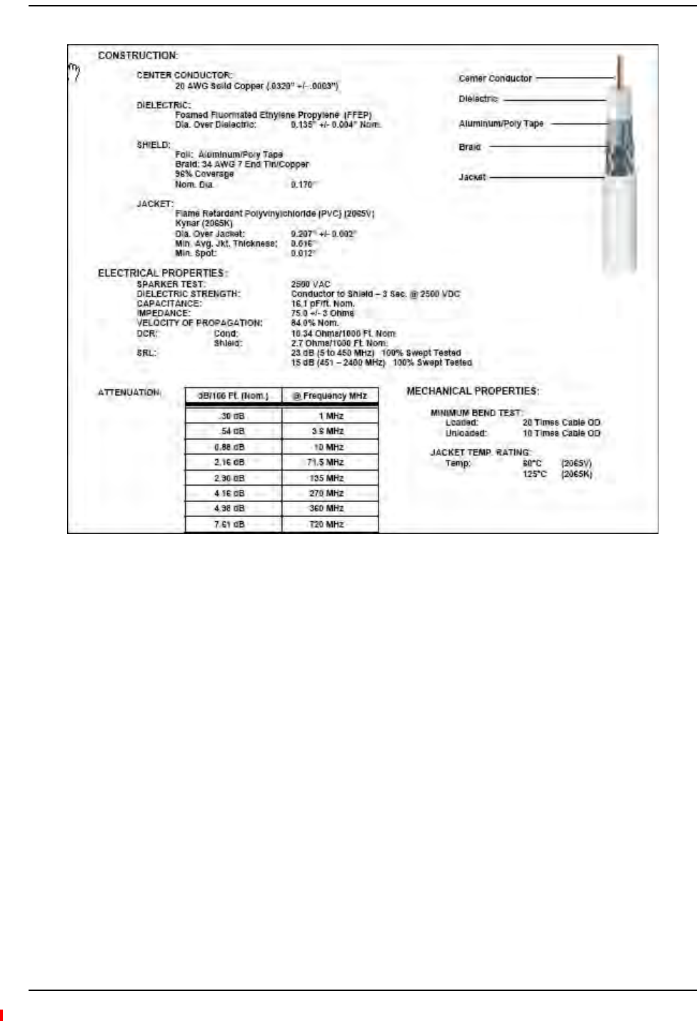
75 Ohm CATV Cable
InterReach Fusion Wideband Installation, Operation, and Reference Manual Page 193
D-620616-0-20 Rev H • TECP-77-044 Issue 7 • May 2013 © 2013 TE Connectivity Ltd.
Figure59.CommScope 2065V for RG-59
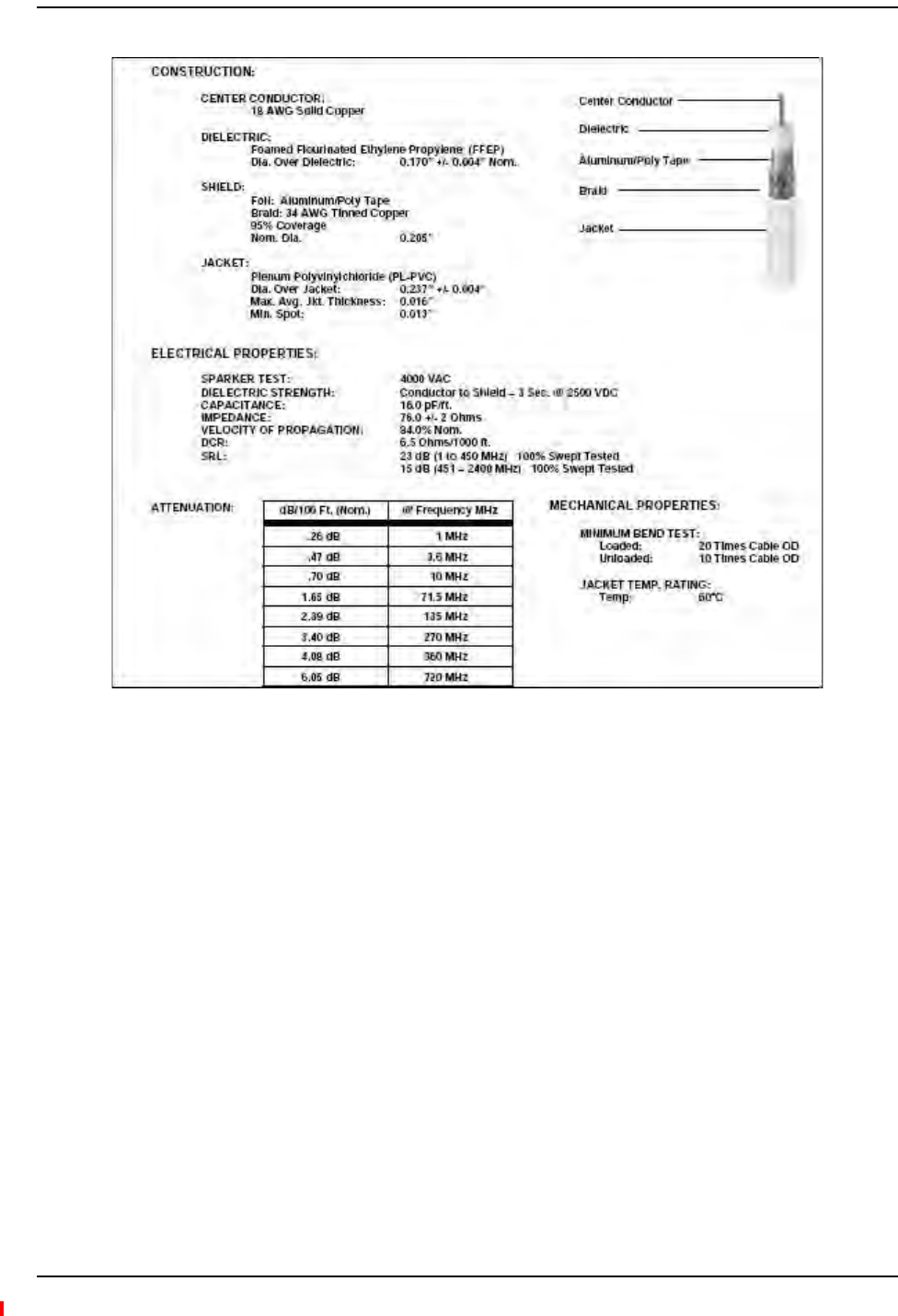
Appendix A: Cables and Connectors
Page 194 InterReach Fusion Wideband Installation, Operation, and Reference Manual
© 2013 TE Connectivity Ltd D-620616-0-20 Rev H • TECP-77-044 Issue 7 • May 2013
Figure60.CommScope 2079V for RG-6

75 Ohm CATV Cable
InterReach Fusion Wideband Installation, Operation, and Reference Manual Page 195
D-620616-0-20 Rev H • TECP-77-044 Issue 7 • May 2013 © 2013 TE Connectivity Ltd.
Figure61.CommScope 2293K for RG-11
NOTE: TErequiressolidcoppercenterconductorCATVcableforproperDCvoltagetotheRAUand
maximumdistances.

Appendix A: Cables and Connectors
Page 196 InterReach Fusion Wideband Installation, Operation, and Reference Manual
© 2013 TE Connectivity Ltd D-620616-0-20 Rev H • TECP-77-044 Issue 7 • May 2013
ConnectorsandToolsforCableEnds
Usethefollowingconnectorsandtoolstopreparethecableends:
•CommScopecablepartnumber:2065V
•Canarepartnumber:FconnectorFP‐C4F
•CrimpToolTC‐1,CrimpDieTCD‐4C,CableStrippreparationtoolTS100E
•CommScopecablepartnumber:2279V
•Canarepartnumber:FconnectorFP‐C55A
•CrimpToolTC‐1,CrimpDieTCD‐35CA,CableStrippreparationtoolTS100E
•CommScopecablepartnumber:2293V
•Canarepartnumber:FconnectorFP‐C71A
•CrimpToolTC‐1,CrimpDieTCD‐7CA,CableStrippreparationtoolTS100E
Ifthemaximumdistanceisnotrequired,thencopper‐cladoversteel‐centerconductorcablemay
beusedtoreducecablecosts.
Table96showCommScopecablechoicesofplenum,non‐plenum,solidcopperconductor,and
copper‐cladover‐steelconductorcablewiththeirpartnumbersandmaximumdistances.
Table96.SystemGain(Loss)RelativetoCATVCableLength
Cable
Type
CommScope
Part Number
Plenum
Rated
Solid Copper
Conductor
Copper Clad
Conductor
Zero-loss RF
Maximum
Length
(meters)
Distance
Where RF
is 10dB
Below Input
RF
(meters)
RG-59 2065V Yes X 130 180
2022V Yes X 100 100*
5572R No X 95 95*
5565 No X 130 180
RG-6 2279V Yes X 140 190
2275V Yes X 140 150*
5726 No X 140 140*
5765 No X 140 190
RG-11 2293K Yes X 235 320
2285K Yes X 235 300*
5913 No X 235 300*
* Exceeding the distance of copper-clad cable will result in the attached RAU becoming non-functional.
If the distance of a cable run is at its maximum and is of concern, TE recommends the use of solid
copper cable to ensure successful operation.

Fiber Optical Cables
InterReach Fusion Wideband Installation, Operation, and Reference Manual Page 197
D-620616-0-20 Rev H • TECP-77-044 Issue 7 • May 2013 © 2013 TE Connectivity Ltd.
FIBEROPTICALCABLES
•ConnectstheMainHubtoExpansionHub(s)
•Transmits(downlink)andreceives(uplink)opticalsignals
•Carriesconfigurationandstatusinformation
•Useindustry‐standard62.5µm/125µmMMForCorningSMF‐28fiber,orequivalent.
•SC/APC(angle‐polished)connectorsarerequiredthroughoutthefibernetwork
(port‐to‐port),includingfiberdistributionpanels
•Distances:
–Multi‐modeFiber:upto500m(1,640ft)–3dBopticallossmaximum
–Single‐modeFiber:upto6km(19,685ft)–3dBopticallossmaximum

Appendix A: Cables and Connectors
Page 198 InterReach Fusion Wideband Installation, Operation, and Reference Manual
© 2013 TE Connectivity Ltd D-620616-0-20 Rev H • TECP-77-044 Issue 7 • May 2013
COAXIALCABLE
•ConnectsaFusionHubtoarepeaterorbasestation(N‐typeconnectors)
•ConnectsanRAUtoapassiveantenna(N‐typeconnectors)

Standard Modem Cable
InterReach Fusion Wideband Installation, Operation, and Reference Manual Page 199
D-620616-0-20 Rev H • TECP-77-044 Issue 7 • May 2013 © 2013 TE Connectivity Ltd.
STANDARDMODEMCABLE
Thiscable(PN4028‐10)connectsamodemtotheFusionHub’sfrontpanelserialport.
Figure62.Standard Modem Cable Pinouts
DB-9 Connector
Pin
DB-25 Connector
Pin
1
2
3
4
5
6
7
8
9
8
3
2
20
7
6
4
5
22
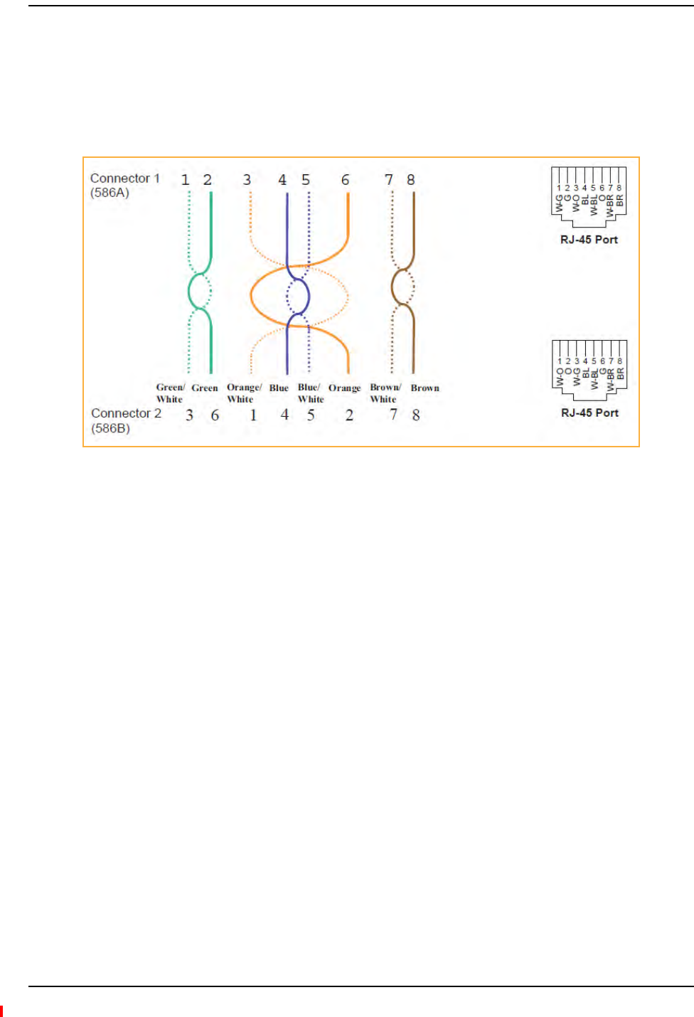
Appendix A: Cables and Connectors
Page 200 InterReach Fusion Wideband Installation, Operation, and Reference Manual
© 2013 TE Connectivity Ltd D-620616-0-20 Rev H • TECP-77-044 Issue 7 • May 2013
TCP/IPCROSS‐OVERCABLE
ATCP/IPcross‐overcable(PN4069‐ADB)isusedtoconnectastandardbrowserPCtothe
AdminBrowserwithaFusionHub.AcableisincludedwiththeFusionHub.Thepinoutsforthis
cableareillustratedinFigure63.
Figure63.Wiring Map for TCP/IP Cable
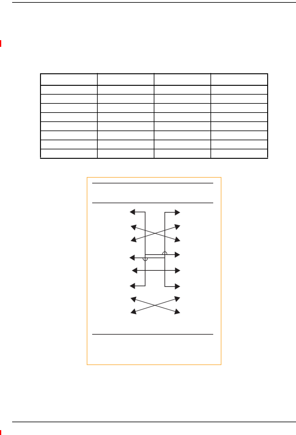
DB-9 to DB-9 Null Modem Cable
InterReach Fusion Wideband Installation, Operation, and Reference Manual Page 201
D-620616-0-20 Rev H • TECP-77-044 Issue 7 • May 2013 © 2013 TE Connectivity Ltd.
DB‐9TODB‐9NULLMODEMCABLE
UseaDB‐9femaletoDB‐9femalenullmodemcabletoconnectthecraftperson’sPC/Laptopto
theRS‐232portonthefrontoftheFusionHubforIPaddressconfiguration.Table97liststhe
cablepinoutandFigure64showsadiagramofitswiring.
Figure64.DB-9 Female to DB-9 Female Null Modem Cable Diagram
Table97.DB‐9FemaletoDB‐9FemaleNullModemCablePinout
From Signal To Signal
P1-4 DTR P2-6, P2-1 DSR, DCD
P1-6 DSR P1-1, P2-4 DCD, DTR
P1-3 TXD P2-2 RXD
P1-2 RXD P2-3 TXD
P1-5 GND P2-5 GND
P1-7 RTS P2-8 CTS
P1-8 CTS P2-7 RTS
P1-9 N/C N/C N/C
DB-9 Connector
Pin
DB-9 Connector
Pin
1
2
3
4
5
6
7
8
9
1
2
3
4
5
6
7
8
9
Note that for each DB-9 connector, pins 1 and 6 are tied
together and sent to pin 4 of the opposite connector,
providing the required handshake signals.

Appendix A: Cables and Connectors
Page 202 InterReach Fusion Wideband Installation, Operation, and Reference Manual
© 2013 TE Connectivity Ltd D-620616-0-20 Rev H • TECP-77-044 Issue 7 • May 2013

InterReach Fusion Wideband Installation, Operation, and Reference Manual Page 203
D-620616-0-20 Rev H • TECP-77-044 Issue 7 • May 2013 ©2013 TE Connectivity Ltd.
APPENDIXB:COMPLIANCE
FusionWidebandSystemApprovalStatus ........................................................................................................................... 204
700MHzLTEProducts............................................................................................................................................................204
800SMR/iDENProducts .........................................................................................................................................................204
850CellularProducts..............................................................................................................................................................204
1800DCSProducts .................................................................................................................................................................204
1900PCSProducts..................................................................................................................................................................204
2100UMTSProducts ..............................................................................................................................................................205
1700/2100AWSProducts ......................................................................................................................................................205
2500WiMAXProducts............................................................................................................................................................205
2600MHzLTEProducts..........................................................................................................................................................205
InterReachFusionWidebandMainHubandExpansionHub.................................................................................................206
HumanExposuretoRF......................................................................................................................................................... 207
Topics Page

Appendix B: Compliance
Page 204 InterReach Fusion Wideband Installation, Operation, and Reference Manual
© 2013 TE Connectivity Ltd D-620616-0-20 Rev H • TECP-77-044 Issue 7 • May 2013
FUSIONWIDEBANDSYSTEMAPPROVALSTATUS
InterReachFusionWidebandhasbeenapprovedasshownbelow.
700MHzLTEProducts
•Safety:UL,CSA,CBSchemecertificatetoIEC60950,3rdEdition,andIEC60950‐1,1stEdition,
withallnationaldeviations.
•EMC:FCCpart15classA
•Radio:FCCpart27
800SMR/iDENProducts
•Safety:UL,CSA,CBSchemecertificatetoIEC60950,3rdEdition,andIEC60950‐1,1stEdition,
withallnationaldeviations.
•EMC:FCCpart15classA
•Radio:FCCpart90
850CellularProducts
•Safety:UL,CSA,CBSchemecertificatetoIEC60950,3rdEdition,andIEC60950‐1,1stEdition,
withallnationaldeviations.
•EMC:FCCpart15classA
•Radio:FCCpart22
1800DCSProducts
•Safety:UL,CSA,CBSchemecertificatetoIEC60950,3rdEdition,andIEC60950‐1,1stEdition,
withallnationaldeviations.
•EMC:EN301489‐8V1.2.1
•Radio:EN300609‐4V9.2.1
1900PCSProducts
•Safety:UL,CSA,CBSchemecertificatetoIEC60950,3rdEdition,andIEC60950‐1,1stEdition,
withallnationaldeviations.
•EMC:FCCpart15classA
•Radio:FCCpart24

Fusion Wideband System Approval Status
InterReach Fusion Wideband Installation, Operation, and Reference Manual Page 205
D-620616-0-20 Rev H • TECP-77-044 Issue 7 • May 2013 © 2013 TE Connectivity Ltd.
2100UMTSProducts
•Safety:UL,CSA,CBSchemecertificatetoIEC60950,3rdEdition,andIEC60950‐1,1stEdition,
withallnationaldeviations.
•EMC:EN301489‐23V1.2.1
•Radio:EN301908‐11V2.3.1
1700/2100AWSProducts
•Safety:UL,CSA,CBSchemecertificatetoIEC60950,3rdEdition,andIEC60950‐1,1stEdition,
withallnationaldeviations.
•EMC:FCCpart15classA
•Radio:FCCpart27
2500WiMAXProducts
•Safety:UL,CSA,CBSchemecertificatetoIEC60950,3rdEdition,andIEC60950‐1,1stEdition,
withallnationaldeviations.
•EMC:FCCpart15classA
•Radio:FCCpart27
2600MHzLTEProducts
•Safety:UL,CSA,CBSchemecertificatetoIEC60950,3rdEdition,andIEC60950‐1,1stEdition,
withallnationaldeviations.
•EMC:EN301489‐23V1.2.1
•Radio:EN301908‐11V2.3.1

Appendix B: Compliance
Page 206 InterReach Fusion Wideband Installation, Operation, and Reference Manual
© 2013 TE Connectivity Ltd D-620616-0-20 Rev H • TECP-77-044 Issue 7 • May 2013
InterReachFusionWidebandMainHubandExpansionHub
•Safety:UL,CSA,CBSchemecertificatetoIEC60950‐1,FirstEdition,withallnational
deviations.
•EMC:CISPR22A
•EMC:CISPR24
NOTE: ForCanadiancustomers,theManufacturer’sratedoutputpower1ofthisequipmentisforsingle
carrieroperation.Forsituationswhenmultiplecarriersignalsarepresent,theratingwouldhave
tobereducedby3.5dB,especiallywheretheoutputsignalisre‐radiatedandcancause
interferencetoadjacentbandusers.Thispowerreductionistobebymeansofinputpoweror
gainreductionandnotbyanattenuatorattheoutputofthedevice.
NOTE: ThisdevicecomplieswithPart15oftheFCCRules.Operationissubjecttothefollowingtwo
conditions:(1)thisdevicemaynotcauseharmfulinterference,and(2)thisdevicemustaccept
anyinterferencereceived,includinginterferencethatmaycauseundesiredoperation.
NOTE: ThisequipmenthasbeentestedandfoundtocomplywiththelimitsforaClassAdigitaldevice,
pursuanttoPart15oftheFCCRules.Theselimitsaredesignedtoprovidereasonableprotection
againstharmfulinterferencewhentheequipmentisoperatedinacommercialenvironment.
Thisequipmentgenerates,uses,andcanradiateradiofrequencyenergyand,ifnotinstalledand
usedinaccordancewiththeinstructionmanual,maycauseharmfulinterferencetoradio
communications.
ThisequipmentcomplieswiththeFCCradiationexposurelimitsforgeneral
population/uncontrolledexposureenvironments.
ChangesormodificationsnotapprovedandperformedbyTEmayvoidtheuser’sauthorityto
operatetheequipment.
1 “Manufacturer’s rated output power” refers to Fusion Wideband’s downlink P1dB. The power per carrier tables take
into account this power reduction for multiple carriers.
WARNING.ThisisNOTaCONSUMERdevice.ItisdesignedforinstallationbyFCC
LICENSEESandQUALIFIEDINSTALLERS.YouMUSThaveanFCCLicenseorexpress
consentofanFCClicenseetooperatethisdevice.Unauthorizedusemayresultinsignificant
forfeiturepenalties,includingpenaltiesinexcessof$100,000foreachcontinuingviolation.
Part 90 Signal Boosters
WARNING.ThisisNOTaCONSUMERdevice.ItisdesignedforinstallationbyFCC
LICENSEESandQUALIFIEDINSTALLERS.YouMUSThaveanFCCLicenseorexpress
consentofanFCClicenseetooperatethisdevice.YouMUSTregisterClassBsignalboosters
(asdefinedin47CFR90.219)onlineatwww.fcc.gov/signal‐boosters/registration.
Unauthorizedusemayresultinsignificantforfeiturepenalties,includingpenaltiesinexcess
of$100,000foreachcontinuingviolation.

Human Exposure to RF
InterReach Fusion Wideband Installation, Operation, and Reference Manual Page 207
D-620616-0-20 Rev H • TECP-77-044 Issue 7 • May 2013 © 2013 TE Connectivity Ltd.
HUMANEXPOSURETORF
TheU.S.FederalCommunicationsCommission(FCC)hasdevelopedguidelinesforevaluationof
humanexposuretoRFemissions.TheguidelinesincorporatelimitsforMaximumPermissible
Exposure(MPE)forpowerdensityoftransmittersoperatingatfrequenciesbetween300kHzand
100GHz.Limitshavebeensetforportable,mobile,andfixedequipment.TEproductsfallinthe
categoryoffixedequipment;productsintendedtobepermanentlysecuredandexposuresare
evaluatedfordistancesgreaterthan20cm(77/8”).Portabledevicesfallintoexposuresofless
than20cm,areSARevaluationsareused.
Antennagainisrestrictedto1.5WERP(2.49WEIRP)inordertosatisfyRFexposurecompliance
requirements.Ifhigherthan1.5WERP,routineMPEevaluationisneeded.Theantennasshould
beinstalledtoprovideatleast20cmfromallpersonstosatisfyMPErequirementsofFCCPart2,
2.1091.
BasicMPEevaluationisperformedbytakingthemaximumpoweroutputoftheequipment,the
gainoftheantennatobeused,anddistancefromtheantenna,referencedinFCCOETBulletin65
“EvaluationCompliancewithFCCGuidelinesforHumanExposuretoRadioFrequencyforElectric
Fields”.
TEproductstransmitwellbelowtheFCCpowerdensitylimits.FCCdefinespoweroutputlimits
at20cmdistanceforvariousfrequencyranges:
•Over300mHzto1.5GHzthelimitisdeterminedbyfrequency/1500
•Above1.5GHzthelimitis1mW/cm2
Thebasicequationfordeterminingpowerdensityis:
S = PG / 4R2
WhereSispowerdensityinmW/cm2
PG,thetransmittedpowerfromtheantennaidentifiedasEIRP(EquivalentIsotropicallyRadiated
Power),istheproductofpoweroutputofdeviceandantennagain,inmW.
Risthedistanceofinterestfromtheantenna.
TypicalInstallationExample:
Assuminganantennaisplacedona10footceiling,foraperson6feettall,thedistancefrom
antennatobodyis4feet(112cm.).
ForaPCS1900remoteunit,themaximumpoweroutput,accordingtothepowertablein
Section6.3MaximumOutputPowerperCarrier6‐4,is16.5dB.
Assuminga7dBiantennaisused,PGintheequationisequalto23.5dB(224mW)EIRP.
UsingS=PG/4R2
S=224/(4x3.14)x(122)2=0.001mW/cm2
Also,assumingaminimumdistanceof20cmaccordingtoFCCregulations:
S=224/(4x3.14)x(20)2=0.04mW/cm2

Appendix B: Compliance
Page 208 InterReach Fusion Wideband Installation, Operation, and Reference Manual
© 2013 TE Connectivity Ltd D-620616-0-20 Rev H • TECP-77-044 Issue 7 • May 2013

InterReach Fusion Wideband Installation, Operation, and Reference Manual Page 209
D-620616-0-20 Rev H • TECP-77-044 Issue 7 • May 2013 ©2013 TE Connectivity Ltd.
APPENDIXC:FAULTS,WARNINGS,STATUSTABLESFOR
FUSION,FUSIONWIDEBAND,FUSIONSINGLESTAR
FaultsReportedbyMainHubs ............................................................................................................................................. 210
FaultsReportedforSystemCPU........................................................................................................................................... 213
FaultsforExpansionHubs.................................................................................................................................................... 214
FaultsforRAUs .................................................................................................................................................................... 216
MessagesforMainHubs...................................................................................................................................................... 217
WarningMessages .................................................................................................................................................................217
StatusMessages .....................................................................................................................................................................217
MessagesforSystemCPUs................................................................................................................................................... 222
MessagesforExpansionHubs .............................................................................................................................................. 223
MessagesforRAUs .............................................................................................................................................................. 226
Thefollowingtablescontainmessagesforallversionsoffirmware,butallmessagesarenot
displayedbyagivenfirmwareversion.
Topics Page

Appendix C: Faults, Warnings, Status Tables for Fusion, Fusion Wideband, Fusion SingleStar
Page 210 InterReach Fusion Wideband Installation, Operation, and Reference Manual
© 2013 TE Connectivity Ltd D-620616-0-20 Rev H • TECP-77-044 Issue 7 • May 2013
FAULTSREPORTEDBYMAINHUBS
Faultsindicateservice‐impactingconditionsandshouldbegivenimmediateattention.
Oncealloftheunitsarepoweredonandthecableconnectionsaremade,thefaultsfromeachunit
canberequestedusingAdminBrowser.StartwiththeFusionorFusionWidebandMainHuband
workdownstream.
Resolveallfaultsfirstandthencheckthewarnings.Takeappropriateactiontoresolvethefaults,
asindicatedinthefollowingtables.Incaseswherethereismorethanonepossiblecause,theyare
listedfromthe“mostlikely”tothe“leastlikely”cause.Actionsarelistedintheorderthatthey
shouldbeperformed;notallactionsmayneedtobedone.
NOTE: IfyouhavearedSTATUSLEDwithoutafaultmessage,itprobablyindicatesthattheunitislocked
out.
Table98.FaultMessagesforMainHubs
Message
Number
Description Reason/Action
{MF01} Software error occurred and recovered. If this happens repeatedly, replace the Hub.
{MF02} Software error occurred and recovered. If this happens repeatedly, replace the Hub.
{MF03} Software error occurred and recovered. If this happens repeatedly, replace the Hub.
{MF04} Software reset occurred and recovered, or firmware
download.
If this happens repeatedly, replace the Hub.
{MF05} Software error occurred and recovered. If this happens repeatedly, replace the Hub.
{MF06} Problem detected in the Hub. Internal communication
reset.
Contact TE Support for more information.
{MF07} Hub power cycle. Hub power cycle.
{MF08} Internal communications failure. No internal communications in preceding 15 minutes.
{MF09} Hardware Reset. Commanded hardware power on reset
{MF10} Band not programmed. Use AdminBrowser to program the band.
{MF11} Hardware failure (DL Pilot PLL). Cycle power once. If fault persists, replace the Hub
{MF12} Hardware failure (DL Pilot Too High). Cycle power once. If fault persists, replace the Hub.
{MF13} Hardware failure (DL Pilot Too Low). Cycle power once. If fault persists, replace the Hub.
{MF14} Hardware failure (54 VDC). 54 VDC power supply is out of range, replace the Hub
{MF15} Hardware failure (RF VDC Power). Loss of DC power to RF circuits, replace the Hub.
{MF16} Self Lockout (All Bands). Hub has shutdown the system due to an internal fault.
System is offline.
{MF17} Hardware failure (DL PLL Band 1). Cycle power once. If fault persists, replace the Hub.
{MF18} Hardware failure (UL PLL Band 1). Cycle power once. If fault persists, replace the Hub
{ML19} Commanded Out-of-service (Band 1). Band 1 commanded out-of-service by User.
{MF20} Hardware failure (UL1 LO2 Band 1). Cycle power once. If the fault persists, replace the Hub.
{MF21} Problem detected in the Hub. Contact TE Support for more information.
{MF22} Problem detected in the Hub. Contact TE Support for more information.
{MF23} Problem detected in the Hub Contact TE Support for more information.
{MF24} Problem detected in the Hub. Contact TE Support for more information.
{MF25} Hardware failure (DL PLL Band 2). Cycle power once. If fault persists, replace the Hub.

Faults Reported by Main Hubs
InterReach Fusion Wideband Installation, Operation, and Reference Manual Page 211
D-620616-0-20 Rev H • TECP-77-044 Issue 7 • May 2013 © 2013 TE Connectivity Ltd.
{MF26} Hardware failure (UL PLL Band 2). Cycle power once. If fault persists, replace the Hub.
{ML27} Commanded Out-of-service (Band 2). Band 2 commanded out-of-service by User.
{MF28} Problem detected in the Hub. Contact TE Support for more information.
{MF29} Problem detected in the Hub. Contact TE Support for more information.
{MF30} Problem detected in the Hub. Contact TE Support for more information.
{MF31} Problem detected in the Hub. Contact TE Support for more information.
{MF32} Problem detected in the Hub. Contact TE Support for more information.
{MF33} Hardware failure (DL PLL Band 3). Cycle power once. If fault persists, replace the Hub.
{MF34} Hardware failure (UL PLL Band 3). Cycle power once. If fault persists, replace the Hub.
{ML35} Commanded Out-of-service (Band 3). Band 3 commanded out-of-service by User.
{MF36} Hardware failure (638 MHz PLL). Cycle power once. If fault persists, replace the Hub.
{MF37} Hardware failure (638 MHz PLL). Cycle power once. If fault persists, replace the Hub.
{MF38} Problem detected in the Hub. Contact TE Support for more information.
{MF39} Problem detected in the Hub. Contact TE Support for more information.
{MF40} Problem detected in the Hub. Contact TE Support for more information.
{MF41} Hardware failure (Optical Power Out). Cycle power once. If the fault persists, replace the Hub.
{MF42} Unable to sync with TDD frame (Band 1). Check input signal and/or user TDD settings.
{MF43} Unable to sync with TDD frame (Band 2). Check input signal and/or user TDD settings.
{MF44} Problem detected in the Hub. Contact TE Support for more information
{MF45} Problem detected in the Hub. Contact TE Support for more information.
{MF46} Problem detected in the Hub. Contact TE Support for more information.
{MF47} Problem detected in the Hub Contact TE Support for more information.
{MF48} Problem detected in the Hub. Contact TE Support for more information.
{MD129} Port 1 Disconnected. Unit is disconnected.
{MD130} Port 2 Disconnected. Unit is disconnected.
{MD131} Port 3 Disconnected. Unit is disconnected.
{MD132} Port 4 Disconnected. Unit is disconnected.
{MD133} Port 5 Disconnected. Unit is disconnected.
{MD134} Port 6 Disconnected. Unit is disconnected.
{MD135} Port 7 Disconnected. Unit is disconnected.
{MD136} Port 8 Disconnected. Unit is disconnected.
{MC137} Port 1 No Communications. No communications with remote unit.
{MC138} Port 2 No Communications. No communications with remote unit.
{MC139} Port 3 No Communications. No communications with remote unit.
{MC140} Port 4 No Communications. No communications with remote unit.
{MC141} Port 5 No Communications. No communications with remote unit.
{MC142} Port 6 No Communications. No communications with remote unit.
{MC143} Port 7 No Communications. No communications with remote unit.
{MC144} Port 8 No Communications. No communications with remote unit.
{MT145} Port 1 Cable Fault. Possible electrical short in the coax cable, or RAU problem.
Table98.FaultMessagesforMainHubs(Cont.)
Message
Number
Description Reason/Action

Appendix C: Faults, Warnings, Status Tables for Fusion, Fusion Wideband, Fusion SingleStar
Page 212 InterReach Fusion Wideband Installation, Operation, and Reference Manual
© 2013 TE Connectivity Ltd D-620616-0-20 Rev H • TECP-77-044 Issue 7 • May 2013
{MT146} Port 2 Cable Fault. Possible electrical short in the coax cable, or RAU problem.
{MT147} Port 3 Cable Fault. Possible electrical short in the coax cable, or RAU problem.
{MT148} Port 4 Cable Fault. Possible electrical short in the coax cable, or RAU problem.
{MT149} Port 5 Cable Fault. Possible electrical short in the coax cable, or RAU problem.
{MT150} Port 6 Cable Fault. Possible electrical short in the coax cable, or RAU problem.
{MT151} Port 7 Cable Fault. Possible electrical short in the coax cable, or RAU problem.
{MT152} Port 8 Cable Fault. Possible electrical short in the coax cable, or RAU problem.
{MT153} Port 1 Trip. Remote Unit is drawing too much current.
{MT154} Port 2 Trip. Remote Unit is drawing too much current.
{MT155} Port 3 Trip. Remote Unit is drawing too much current.
{MT156} Port 4 Trip. Remote Unit is drawing too much current.
{MT157} Port 5 Trip. Remote Unit is drawing too much current.
{MT158} Port 6 Trip. Remote Unit is drawing too much current.
{MT159} Port 7 Trip. Remote Unit is drawing too much current.
{MT160} Port 8 Trip. Remote Unit is drawing too much current.
{MF161} Problem detected in the Hub. Contact TE Support for more information.
{MF162} Problem detected in the Hub. Contact TE Support for more information.
{MF163} Problem detected in the Hub. Contact TE Support for more information.
{MF164} Problem detected in the Hub. Contact TE Support for more information.
{MF165} Problem detected in the Hub. Contact TE Support for more information.
{MF166} Problem detected in the Hub. Contact TE Support for more information.
{MF167} Problem detected in the Hub. Contact TE Support for more information.
{MF168} Problem detected in the Hub. Contact TE Support for more information.
{MF169} Problem detected in the Hub. Contact TE Support for more information.
{MF170} Problem detected in the Hub. Contact TE Support for more information.
{MF171} Problem detected in the Hub. Contact TE Support for more information.
{MF172} Problem detected in the Hub. Contact TE Support for more information.
{MF173} Problem detected in the Hub. Contact TE Support for more information.
{MF174} Problem detected in the Hub. Contact TE Support for more information.
{MF175} Problem detected in the Hub. Contact TE Support for more information.
{MF176} Problem detected in the Hub. Contact TE Support for more information.
Table98.FaultMessagesforMainHubs(Cont.)
Message
Number
Description Reason/Action

Faults Reported for System CPU
InterReach Fusion Wideband Installation, Operation, and Reference Manual Page 213
D-620616-0-20 Rev H • TECP-77-044 Issue 7 • May 2013 © 2013 TE Connectivity Ltd.
FAULTSREPORTEDFORSYSTEMCPU
Table99.FaultsforSystemCPU
Message
Number
Description Reason/Action
{SF01} No internal communications. No internal communications in preceding 2 minutes. Power cycle to
clear.
{SF02} Unable to open file (sysinfo). System CPU rebooted.
{SF03} Unable to open file (sysstat). System CPU rebooted.
{SF04} Invalid internal response. System CPU rebooted, internal command does not return valid response
after 4 retries.
{SF05} No MAC address. System CPU rebooted, unable to read MAC address from the Ethernet
driver.
{SF06} Unable to open file (sysinfo_org). System CPU rebooted.
{SF07} Unable to open file (sbc_status). System CPU rebooted.
{SF08} Invalid internal field response. System CPU rebooted, internal command format invalid.
{SF09} Unable to open file (fileTTL). System CPU rebooted.
{SF10} Invalid internal ASCII response. System CPU rebooted, illegal number of bytes.
{SF11} Unable to open file (sysalarm). System CPU rebooted.
{SF12} Unable to open file (password_etb). System CPU rebooted.
{SF13} Unable to open file (CRC). System CPU rebooted.
{SF14} Problem detected in the System CPU. Contact TE Support for more information.
{SF15} pThread not executing. System CPU rebooted.
{SF16} Problem detected in the System CPU. Contact TE Support for more information.
{SF17} Problem detected in the System CPU. Contact TE Support for more information.
{SF18} Problem detected in the System CPU. Contact TE Support for more information.
{SF19} Problem detected in the System CPU. Contact TE Support for more information.
{SF20} Problem detected in the System CPU. Contact TE Support for more information.
{SF21} Problem detected in the System CPU. Contact TE Support for more information.
{SF22} Problem detected in the System CPU. Contact TE Support for more information.
{SF23} Problem detected in the System CPU. Contact TE Support for more information.
{SF24} Problem detected in the System CPU. Contact TE Support for more information.
{SF25} Problem detected in the System CPU. Contact TE Support for more information.
{SF26} Problem detected in the System CPU. Contact TE Support for more information.
{SF27} Problem detected in the System CPU. Contact TE Support for more information.
{SF28} Problem detected in the System CPU. Contact TE Support for more information.
{SF29} Problem detected in the System CPU. Contact TE Support for more information.
{SF30} Problem detected in the System CPU. Contact TE Support for more information.
{SF31} Problem detected in the System CPU. Contact TE Support for more information.
{SF32} Problem detected in the System CPU. Contact TE Support for more information.

Appendix C: Faults, Warnings, Status Tables for Fusion, Fusion Wideband, Fusion SingleStar
Page 214 InterReach Fusion Wideband Installation, Operation, and Reference Manual
© 2013 TE Connectivity Ltd D-620616-0-20 Rev H • TECP-77-044 Issue 7 • May 2013
FAULTSFOREXPANSIONHUBS
Table100.FaultMessagesforExpansionHubs
Message
Number
Description Reason/Action
{EF01} Software error occurred and recovered. If this happens repeatedly, replace the Hub.
{EF02} Software reset occurred and recovered, or
firmware download.
If this happens repeatedly, replace the Hub.
{EF03} Software reset occurred and recovered. If this happens repeatedly, replace the Hub.
{EF04} Software reset occurred and recovered. If this happens repeatedly, replace the Hub.
{EF05} Software error occurred and recovered. If this happens repeatedly, replace the Hub.
{EF06} Firmware download. Firmware download.
{EF07} Hub power cycle. Hub power cycle.
{EF08} MH communications failure. No communications from MH in THE preceding 90 seconds.
{EF09} MH communications failure. EH uplink messages not getting to the MH.
{EF10} Hardware failure (PLL). Cycle power once. If the fault persists, replace the Hub.
{EF11} Hardware failure (54 VDC). 54 VDC power supply is out of range, replace the Hub.
{EF12} Problem detected in the EH. Contact TE Support for more information.
{EF13} Band not programmed. Cycle power once. If the fault persists, replace the Hub.
{EF14} Low optical input power. Check downlink fiber connections.
{EF15} Hardware failure (Optical Output Power). Cycle power once. If the fault persists, replace the Hub.
{EF16} Self Lockout (All Bands). The Hub has shutdown the system due to an internal fault. The
system is offline.
{EF17} Commanded Out-of-service (Band 1). Band 1 commanded out-of-service by the user.
{EF18} Fault lockout (Band 1). Band 1 out-of-service due to an MH fault.
{EF19} Problem detected in the EH. Contact TE Support for more information.
{EF20} Problem detected in the EH. Contact TE Support for more information.
{EF21} Problem detected in the EH. Contact TE Support for more information.
{EF22} Problem detected in the EH. Contact TE Support for more information.
{EF23} Problem detected in the EH. Contact TE Support for more information.
{EF24} Problem detected in the EH. Contact TE Support for more information.
{EF25} Commanded Out-of-service (Band 2). Band 2 commanded out-of-service by the user.
{EF26} Fault lockout (Band 2). Band 2 out-of-service due to MH fault.
{EF27} Problem detected in the EH. Contact TE Support for more information.
{EF28} Problem detected in the EH. Contact TE Support for more information.
{EF29} Problem detected in the EH. Contact TE Support for more information.
{EF30} Problem detected in the EH. Contact TE Support for more information.
{EF31} Problem detected in the EH. Contact TE Support for more information.
{EF32} Problem detected in the EH. Contact TE Support for more information.
{EF33} Commanded Out-of-service (Band 3). Band 3 commanded out-of-service by the user.
{EF34} Fault lockout (Band 3). Band 3 out-of-service due to an MH fault.
{EF35} Problem detected in the EH. Contact TE Support for more information.
{EF36} Problem detected in the EH. Contact TE Support for more information.

Faults for Expansion Hubs
InterReach Fusion Wideband Installation, Operation, and Reference Manual Page 215
D-620616-0-20 Rev H • TECP-77-044 Issue 7 • May 2013 © 2013 TE Connectivity Ltd.
{EF37} Problem detected in the EH. Contact TE Support for more information.
{EF38} Problem detected in the EH. Contact TE Support for more information.
{EF39} Problem detected in the EH. Contact TE Support for more information.
{EF40} Problem detected in the EH. Contact TE Support for more information.
{ED129} Port 1 Disconnected. Unit is disconnected.
{ED130} Port 2 Disconnected. Unit is disconnected.
{ED131} Port 3 Disconnected. Unit is disconnected.
{ED132} Port 4 Disconnected. Unit is disconnected.
{ED133} Port 5 Disconnected. Unit is disconnected.
{ED134} Port 6 Disconnected. Unit is disconnected.
{ED135} Port 7 Disconnected. Unit is disconnected.
{ED136} Port 8 Disconnected. Unit is disconnected.
{EC137} Port 1 No Communications. No communications with remote unit.
{EC138} Port 2 No Communications. No communications with remote unit.
{EC139} Port 3 No Communications. No communications with remote unit.
{EC140} Port 4 No Communications. No communications with remote unit.
{EC141} Port 5 No Communications. No communications with remote unit.
{EC142} Port 6 No Communications. No communications with remote unit.
{EC143} Port 7 No Communications. No communications with remote unit.
{EC144} Port 8 No Communications. No communications with remote unit.
{ET145} Port 1 Cable Fault. Possible electrical short in the coaxial cable, or an RAU problem.
{ET146} Port 2 Cable Fault. Possible electrical short in the coaxial cable, or an RAU problem.
{ET147} Port 3 Cable Fault. Possible electrical short in the coaxial cable, or an RAU problem.
{ET148} Port 4 Cable Fault. Possible electrical short in the coaxial cable, or an RAU problem.
{ET149} Port 5 Cable Fault. Possible electrical short in the coaxial cable, or an RAU problem.
{ET150} Port 6 Cable Fault. Possible electrical short in the coaxial cable, or an RAU problem.
{ET151} Port 7 Cable Fault. Possible electrical short in the coaxial cable, or an RAU problem.
{ET152} Port 8 Cable Fault. Possible electrical short in the coaxial cable, or an RAU problem.
{ET153} Port 1 Trip. The Remote Unit is drawing too much current.
{ET154} Port 2 Trip. The Remote Unit is drawing too much current.
{ET155} Port 3 Trip. The Remote Unit is drawing too much current.
{ET156} Port 4 Trip. The Remote Unit is drawing too much current.
{ET157} Port 5 Trip. The Remote Unit is drawing too much current.
{ET158} Port 6 Trip. The Remote Unit is drawing too much current.
{ET159} Port 7 Trip. The Remote Unit is drawing too much current.
{ET160} Port 8 Trip. The Remote Unit is drawing too much current.
Table100.FaultMessagesforExpansionHubs(Cont.)
Message
Number
Description Reason/Action

Appendix C: Faults, Warnings, Status Tables for Fusion, Fusion Wideband, Fusion SingleStar
Page 216 InterReach Fusion Wideband Installation, Operation, and Reference Manual
© 2013 TE Connectivity Ltd D-620616-0-20 Rev H • TECP-77-044 Issue 7 • May 2013
FAULTSFORRAUS
Table101.FaultsforRAUs
Message
Number
Description Reason/Action
{RF01} Software error occurred and recovered. If this happens repeatedly, replace the RAU.
{RF02} Software error occurred and recovered. If this happens repeatedly, replace the RAU.
{RF03} Software error occurred and recovered. If this happens repeatedly, replace the RAU.
{RF04} Software reset occurred and recovered, or firmware
download.
If this happens repeatedly, replace the RAU.
{RF05} Software error occurred and recovered. If this happens repeatedly, replace the RAU.
{RF06} Problem detected in the RAU. Contact TE Support for more information.
{RF07} RAU power cycle. RAU power cycle.
{RF08} Problem detected in the RAU. Contact TE Support for more information.
{RF09} Invalid band. The RAU doesn't support programmed band. Check the
RAU type against the band programmed in the hub.
{RF10} Low input DC voltage. Check the coaxial cable for high RF loss. Try another Hub
port. If the fault persists, replace the RAU. If the fault clears,
mark the Hub port as unusable and replace the Hub when
possible.
{RF11} Hardware Failure (DL PLL Band 1). Cycle power once. If the fault persists, replace the RAU.
{RF12} Hardware Failure (DL PLL Band 2). Cycle power once. If the fault persists, replace the RAU.
{RF13} Hardware Failure (DL PLL Band 3). Cycle power once. If the fault persists, replace the RAU.
{RF14} Hardware Failure (UL PLL Band 1). Cycle power once. If the fault persists, replace the RAU.
{RF15} Hardware Failure (UL PLL Band 2). Cycle power once. If the fault persists, replace the RAU.
{RF16} Hardware Failure (UL PLL Band 3). Cycle power once. If the fault persists, replace the RAU.
{RF17} Hardware Failure (PA Band 1). Cycle power once. If the fault persists, replace the RAU.
{RF18} Hardware Failure (PA Band 2). Cycle power once. If the fault persists, replace the RAU.
{RF19} Hardware Failure (PA Band 3). Cycle power once. If the fault persists, replace the RAU.
{RF20} Hardware Failure (UL Pilot). Cycle power once. If the fault persists, replace the RAU.
{RL21} Commanded Out-of-service (Band 1). Band 1 commanded out-of-service by User. Command
In-Service on Band 1 to restore service.
{RL22} Commanded Out-of-service (Band 2). Band 2 commanded out-of-service by User. Command
In-Service on Band 2 to restore service.
{RL23} Commanded Out-of-service (Band 3). Band 3 commanded out-of-service by User. Command
In-Service on Band 3 to restore service.
{RF24} Problem detected in the RAU. Contact TE Support for more information.
{RX25} Commanded shutdown (Band 1). Check the status of hub to which the RAU is connected.
{RX26} Commanded shutdown (Band 2). Check the status of hub to which the RAU is connected.
{RX27} Commanded shutdown (Band 3). Check the status of the hub to which the RAU is connected.
{RF28} Internal shutdown (Band 1). RAU Fault condition in band 1 path (or common path).
{RF29} Internal shutdown (Band 2). RAU Fault condition in band 2 path (or common path).
{RF30} Internal shutdown (Band 3). RAU Fault condition in band 3 path (or common path).
{RF31} Problem detected in the system. Contact TE Support for more information.
{RF32} Problem detected in the RAU. Contact TE Support for more information.

Messages for Main Hubs
InterReach Fusion Wideband Installation, Operation, and Reference Manual Page 217
D-620616-0-20 Rev H • TECP-77-044 Issue 7 • May 2013 © 2013 TE Connectivity Ltd.
MESSAGESFORMAINHUBS
WarningMessages
Warningsalertyoutoconditionsthatindicatepossibleserviceimpact.Warningsaredisplayedin
theMessagespaneinredlettering.
Beforeaddressingwarnings,ensurethatallfaultsareresolved.Takeappropriateactionto
resolvethewarnings,asindicatedinthefollowingtables.
NOTE: AdminBrowserv000007orhigherdisplaysevents(faults,warnings,orstatusmessages)
dependingonyourviewpreference.Tochangeyourviewpreference,refertoSection3.5,
“Faults,Warnings,andStatusMessages”oftheFusionInstallation,Operation,andMaintenance
Manual.
StatusMessages
Statusmessagesalertyoutoconditionsthatareimportant,butgenerallydonotimpactservice.
Statusmessagesalertyoutoconditionsthatareimportant,butgenerallydonotimpactservice.
StatusmessagesaredisplayedintheMessagespaneinbluelettering.
NOTE: AdminBrowserv000007orhigherdisplaysevents(faults,warnings,orstatusmessages)
dependingonyourviewpreference.Tochangeyourviewpreference,refertoSection3.5,
“Faults,Warnings,andStatusMessages”oftheFusionInstallation,Operation,andMaintenance
Manual.
NOTE: Theiconsdisplayedinthesystemstatustreeassumethattherearenootherfaults,warnings,or
statuspresent.
InTable102onpage218,themessagenumberisinthefollowingform:
[Mnn]/X
where
•nnequalsthemessagenumber
•Xequalsthedefaultofoneofthefollowing
–S—Status
–W—Warning.

Appendix C: Faults, Warnings, Status Tables for Fusion, Fusion Wideband, Fusion SingleStar
Page 218 InterReach Fusion Wideband Installation, Operation, and Reference Manual
© 2013 TE Connectivity Ltd D-620616-0-20 Rev H • TECP-77-044 Issue 7 • May 2013
Table102.Warnings/StatusMessagesforMainHubs
Message
Number/
Default
Description Reason/Action
[M01]/S Fan 1 failure. Check the fan for rotation, air flow blockage, and dust. Replace the
Hub on high temperature warning.
[M02]/S Fan 2 failure. Check the fan for rotation, air flow blockage, and dust. Replace the
Hub on high temperature warning.
[M03]/S 54 VDC Pwr Supply Fan failure. Check the fan for rotation, air flow blockage, and dust. Replace the
Hub on high temperature warning.
[M04]/W 5 VDC Monitor. DC power out of range, replace the Hub.
[M05]/W 9 VDC Monitor. DC power out of range, replace the Hub.
[M06]/W 54 VDC Monitor. DC power out of range, replace the Hub.
[M07]/W 3 VDC Monitor. DC power out of range, replace the Hub.
[M08]/W 12 VDC Monitor. DC power out of range, replace the Hub.
[M09]/W Temperature High. Reduce ambient temperature, check for air flow blockage, fan
rotation.
[M10]/W -5 VDC Monitor. DC power is out of range, replace the Hub.
[M11]/W High laser current. Output laser failure possible, replace the Hub when possible.
[M12]/W DL path loss is too high Replace the Hub.
[M13]/S Low input optical (Port 1). Check the uplink fiber.
[M14]/S Low input optical (Port 2). Check the uplink fiber.
[M15]/S Low input optical (Port 3). Check the uplink fiber.
[M16]/S Low input optical (Port 4). Check the uplink fiber.
[M17]/S Hardware failure (Test Tone PLL Band 1). Unable to perform DL system test.
[M18]/S Hardware failure (Test Tone Too High Band 1). Unable to perform DL system test.
[M19]/S Hardware failure (Test Tone Too Low Band 1). Unable to perform DL system test.
[M20]/W Overdrive limiter active (Band 1). Reduce input signal power to avoid potential component damage.
[M21]/W CEMark limiter at maximum (Band 1). Reduce input signal power to avoid drop in system gain.
[M22]/W No DL test tone (Band 1). Hub DL gain is low.
[M23]/S No UL test tone (Band 1). Hub UL path gain is low.
[M24]/S Problem detected in the system. Contact TE Support for more information.
[M25]/S Hardware failure (Test Tone PLL Band 2). Unable to perform DL system test. Replace the hub when possible.
[M26]/S Hardware failure (Test Tone Too High Band 2). Unable to perform DL system test. Replace the hub when possible.
[M27]/S Hardware failure (Test Tone Too Low Band 2). Unable to perform DL system test. Replace the hub when possible.
[M28]/W Overdrive limiter active (Band 2). Reduce input signal power to avoid potential component damage.
[M29]/W CEMark limiter at maximum (Band 2). Reduce input signal power to avoid drop in system gain.
[M30]/W No DL test tone (Band 2). Hub DL path gain is low.
[M31]/S No UL test tone (Band 2). Hub UL path gain is low.
[M32]/S Problem detected in the system. Contact TE Support for more information.
[M33]/S Hardware failure (Test Tone PLL Band 3). Unable to perform DL system test.
[M34]/S Hardware failure (Test Tone Too High Band 3). Unable to perform DL system test.
[M35]/S Hardware failure (Test Tone Too Low Band 3). Unable to perform DL system test.
[M36]/W Overdrive limiter active (Band 3). Reduce input signal power to avoid potential component damage.

Messages for Main Hubs
InterReach Fusion Wideband Installation, Operation, and Reference Manual Page 219
D-620616-0-20 Rev H • TECP-77-044 Issue 7 • May 2013 © 2013 TE Connectivity Ltd.
[M37]/W CEMark limiter at maximum (Band 3). Reduce input signal power to avoid drop in system gain.
[M38]/W No DL test tone (Band 3). Hub DL path gain is low.
[M39]/S No UL test tone (Band 3). Hub UL path gain is low.
[M40]/S Problem detected in the Hub. Contact TE Support for more information.
[M41]/W Port 1 No DL test tone (Band 1). Hub/Port DL path gain is low.
[M42]/W Port 2 No DL test tone (Band 1). Hub/Port DL path gain is low.
[M43]/W Port 3 No DL test tone (Band 1). Hub/Port DL path gain is low.
[M44]/W Port 4 No DL test tone (Band 1). Hub/Port DL path gain is low.
[M45]/W Port 5 No DL test tone (Band 1). Hub/Port DL path gain is low.
[M46]/W Port 6 No DL test tone (Band 1). Hub/Port DL path gain is low.
[M47]/W Port 7 No DL test tone (Band 1). Hub/Port DL path gain is low.
[M48]/W Port 8 No DL test tone (Band 1). Hub/Port DL path gain is low.
[M49]/W Port 1 No DL test tone (Band 2). Hub/Port DL path gain is low.
[M50]/W Port 2 No DL test tone (Band 2). Hub/Port DL path gain is low.
[M51]/W Port 3 No DL test tone (Band 2). Hub/Port DL path gain is low.
[M52]/W Port 4 No DL test tone (Band 2). Hub/Port DL path gain is low.
[M53]/W Port 5 No DL test tone (Band 2). Hub/Port DL path gain is low.
[M54]/W Port 6 No DL test tone (Band 2). Hub/Port DL path gain is low.
[M55]/W Port 7 No DL test tone (Band 2). Hub/Port DL path gain is low.
[M56]/W Port 8 No DL test tone (Band 2). Hub/Port DL path gain is low.
[M57]/W Port 1 No DL test tone (Band 3). Hub/Port DL path gain is low.
[M58]/W Port 2 No DL test tone (Band 3). Hub/Port DL path gain is low.
[M59]/W Port 3 No DL test tone (Band 3). Hub/Port DL path gain is low.
[M60]/W Port 4 No DL test tone (Band 3). Hub/Port DL path gain is low.
[M61]/W Port 5 No DL test tone (Band 3). Hub/Port DL path gain is low.
[M62]/W Port 6 No DL test tone (Band 3). Hub/Port DL path gain is low.
[M63]/W Port 7 No DL test tone (Band 3). Hub/Port DL path gain is low.
[M64]/W Port 8 No DL test tone (Band 3). Hub/Port DL path gain is low.
[M65]/S No UL test tone Port 1 (Band 1). Hub/Port UL path gain is low.
[M66]/S No UL test tone Port 2 (Band 1). Hub/Port UL path gain is low.
[M67]/S No UL test tone Port 3 (Band 1). Hub/Port UL path gain is low.
[M68]/S No UL test tone Port 4 (Band 1). Hub/Port UL path gain is low.
[M69]/S No UL test tone Port 1 (Band 2). Hub/Port UL path gain is low.
[M70]/S No UL test tone Port 2 (Band 2). Hub/Port UL path gain is low.
[M71]/S No UL test tone Port 3 (Band 2). Hub/Port UL path gain is low.
[M72]/S No UL test tone Port 4 (Band 2). Hub/Port UL path gain is low.
[M73]/S No UL test tone Port 1 (Band 3). Hub/Port UL path gain is low.
[M74]/S No UL test tone Port 2 (Band 3). Hub/Port UL path gain is low.
[M75]/S No UL test tone Port 3 (Band 3). Hub/Port UL path gain is low.
Table102.Warnings/StatusMessagesforMainHubs(Cont.)
Message
Number/
Default
Description Reason/Action

Appendix C: Faults, Warnings, Status Tables for Fusion, Fusion Wideband, Fusion SingleStar
Page 220 InterReach Fusion Wideband Installation, Operation, and Reference Manual
© 2013 TE Connectivity Ltd D-620616-0-20 Rev H • TECP-77-044 Issue 7 • May 2013
[M76]/S No UL test tone Port 4 (Band 3). Hub/Port UL path gain is low.
[M77]/S Problem detected in the Hub. Contact TE Support for more information.
[M78]/S Problem detected in the Hub. Contact TE Support for more information.
[M79]/S Problem detected in the Hub. Contact TE Support for more information.
[M80]/S Problem detected in the Hub. Contact TE Support for more information.
[M81]/W Port 1 DL path loss is high. If the problem is on more than one port, replace the Hub. Switch
the cable connection to a different hub port until the Hub can be
replaced.
[M82]/W Port 2 DL path loss is high. If the problem is on more than one port, replace the Hub. Switch
the cable connection to a different hub port until the Hub can be
replaced.
[M83]/W Port 3 DL path loss is high. If the problem is on more than one port, replace the Hub. Switch
the cable connection to a different hub port until the Hub can be
replaced.
[M84]/W Port 4 DL path loss is high. If the problem is on more than one port, replace the Hub. Switch
the cable connection to a different hub port until the Hub can be
replaced.
[M85]/W Port 5 DL path loss is high. If the problem is on more than one port, replace the Hub. Switch
the cable connection to a different hub port until the Hub can be
replaced.
[M86]/W Port 6 DL path loss is high. If the problem is on more than one port, replace the Hub. Switch
the cable connection to a different hub port until the Hub can be
replaced.
[M87]/W Port 7 DL path loss is high. If the problem is on more than one port, replace the Hub. Switch
the cable connection to a different hub port until the Hub can be
replaced.
[M88]/W Port 8 DL path loss is high. If the problem is on more than one port, replace the Hub. Switch
the cable connection to a different hub port until the Hub can be
replaced.
[M89]/W Port 1 UL path loss is high. Check the cable for high RF loss. Switch the cable connection to a
different hub port. If the problem on more than one port, replace
the Hub, otherwise replace the RAU.
[M90]/W Port 2 UL path loss is high. Check the cable for high RF loss. Switch the cable connection to a
different hub port. If the problem is on more than one port, replace
the Hub, otherwise replace the RAU.
[M91]/W Port 3 UL path loss is high. Check the cable for high RF loss. Switch the cable connection to a
different hub port. If the problem is on more than one port, replace
the Hub, otherwise replace the RAU.
[M92]/W Port 4 UL path loss is high. Check the cable for high RF loss. Switch the cable connection to a
different hub port. If the problem is on more than one port, replace
the Hub, otherwise replace the RAU.
[M93]/W Port 5 UL path loss is high. Check the cable for high RF loss. Switch the cable connection to a
different hub port. If the problem is on more than one port, replace
the Hub, otherwise replace the RAU.
[M94]/W Port 6 UL path loss is high. Check the cable for high RF loss. Switch the cable connection to a
different hub port. If the problem is on more than one port, replace
the Hub, otherwise replace the RAU.
Table102.Warnings/StatusMessagesforMainHubs(Cont.)
Message
Number/
Default
Description Reason/Action

Messages for Main Hubs
InterReach Fusion Wideband Installation, Operation, and Reference Manual Page 221
D-620616-0-20 Rev H • TECP-77-044 Issue 7 • May 2013 © 2013 TE Connectivity Ltd.
[M95]/W Port 7 UL path loss is high. Check the cable for high RF loss. Switch the cable connection to a
different hub port. If the problem is on more than one port, replace
the Hub, otherwise replace the RAU.
[M96]/W Port 8 UL path loss is high. Check the cable for high RF loss. Switch the cable connection to a
different hub port. If the problem is on more than one port, replace
the Hub, otherwise replace the RAU.
[M97]/W Port 1 UL path exceeds maximum gain. If the problem is common to more than one port, replace the Hub,
otherwise check the RAU.
[M98]/W Port 2 UL path exceeds maximum gain. If the problem is common to more than one port, replace the Hub,
otherwise check the RAU.
[M99]/W Port 2 UL path exceeds maximum gain. If the problem is common to more than one port, replace the Hub,
otherwise check the RAU.
[M100]/W Port 2 UL path exceeds maximum gain. If the problem is common to more than one port, replace the Hub,
otherwise check the RAU.
[M101]/W Port 2 UL path exceeds maximum gain. If the problem is common to more than one port, replace the Hub,
otherwise check the RAU.
[M102]/W Port 2 UL path exceeds maximum gain. If the problem is common to more than one port, replace the Hub,
otherwise check the RAU.
[M103]/W Port 2 UL path exceeds maximum gain. If the problem is common to more than one port, replace the Hub,
otherwise check the RAU.
[M104]/W Port 8 UL path exceeds maximum gain. If the problem is common to more than one port, replace the Hub,
otherwise check the RAU.
[M105]/W Port 1 54 VDC Power Enabled. Caution: Port 54 VDC power may be present at the output.
[M106]/W Port 2 54 VDC Power Enabled. Caution: Port 54 VDC power may be present at the output.
[M107]/W Port 3 54 VDC Power Enabled. Caution: Port 54 VDC power may be present at the output.
[M108]/W Port 4 54 VDC Power Enabled. Caution: Port 54 VDC power may be present at the output.
[M109]/W Port 5 54 VDC Power Enabled. Caution: Port 54 VDC power may be present at the output.
[M110]/W Port 6 54 VDC Power Enabled. Caution: Port 54 VDC power may be present at the output.
[M111]/W Port 7 54 VDC Power Enabled. Caution: Port 54 VDC power may be present at the output.
[M112]/W Port 8 54 VDC Power Enabled. Caution: Port 54 VDC power may be present at the output.
Table102.Warnings/StatusMessagesforMainHubs(Cont.)
Message
Number/
Default
Description Reason/Action

Appendix C: Faults, Warnings, Status Tables for Fusion, Fusion Wideband, Fusion SingleStar
Page 222 InterReach Fusion Wideband Installation, Operation, and Reference Manual
© 2013 TE Connectivity Ltd D-620616-0-20 Rev H • TECP-77-044 Issue 7 • May 2013
MESSAGESFORSYSTEMCPUS
InTable103,themessagenumberisinthefollowingform:
[Snn]/X
where
•nnequalsthemessagenumber
•Xequalsthedefaultofoneofthefollowing
–S—Status
–W—Warning.
Table103.Warning/StatusMessagesforSystemCPUs
Message
Number/
Default
Description Reason/Action
[S01]/W Alarm Input 1. Check equipment connected to alarm input 1.
[S02]/W Alarm Input 2. Check equipment connected to alarm input 2.
[S03]/W Alarm Input 3. Check equipment connected to alarm input 3.
[S04]/S Performed System Test System has just performed system test.
[S05]/S Problem detected in the System CPU. Contact TE Support for more information.
[S06]/S Loaded default etb file. Contact TE Support for more information.
[S07]/S Loaded default SBC status file. Contact TE Support for more information.
[S08]/S Problem detected in the System CPU. Contact TE Support for more information.
[S09]/S TTL is full. Retrieve the TTL and erase.
[S10]/S Problem detected in the System CPU. Contact TE Support for more information.
[S11]/S Problem detected in the System CPU. Contact TE Support for more information.
[S12]/S Loaded default Password file. Contact TE Support for more information.
[S13]/S Loaded default sys config file. Contact TE Support for more information.
[S14]/S Communication retries exceeded. Attempted command three times without response.
[S15]/S Problem detected in the System CPU. Contact TE Support for more information.
[S16]/S Problem detected in the System CPU. Contact TE Support for more information.

Messages for Expansion Hubs
InterReach Fusion Wideband Installation, Operation, and Reference Manual Page 223
D-620616-0-20 Rev H • TECP-77-044 Issue 7 • May 2013 © 2013 TE Connectivity Ltd.
MESSAGESFOREXPANSIONHUBS
Table104.Warning/StatusMessageforExpansionHubs
Message
Number/De
fault
Description Reason/Action
[E01]/W Alarm Input 1. Check the equipment connected to alarm input 1.
[E02]/W Alarm Input 2. Check the equipment connected to alarm input 2.
[E03]/W Alarm Input 3. Check the equipment connected to alarm input 3.
[E04]/S Problem detected in the EH. Contact TE Support for more information.
[E05]/W SNMP Trap #1. TBD.
[E06]/W SNMP Trap #2. TBD.
[E07]/W SNMP Trap #3. TBD.
[E08]/S Problem detected in the EH. Contact TE Support for more information.
[E09]/S Fan 1 failure. Check the fan for proper rotation, air flow blockage, and dust accumulation.
Replace the Hub on high temperature warning.
[E10]/S Fan 2 failure. Check the fan for proper rotation, air flow blockage, and dust accumulation.
Replace the Hub on high temperature warning.
[E11]/W -5 VDC Monitor. DC power out of range, replace the Hub.
[E12]/W 5 VDC Monitor. DC power out of range, replace the Hub.
[E13]/W 9 VDC Monitor. DC power out of range, replace the Hub.
[E14]/W 54 VDC Pwr Supply failure. DC port power supply out of range, replace the Hub.
[E15]/W 3 VDC Monitor. DC power out of range, replace the Hub.
[E16]/W 12 VDC Monitor. DC power out of range, replace the Hub.
[E17]/W Temperature High. Reduce the ambient temperature, check for air flow blockage, fan rotation.
[E18]/W DL path exceeds maximum gain. If the problem is common to more than one port, replace the MH, otherwise
check the EH.
[E19]/W DL path loss is high. Check the cable for high RF loss. Switch the cable connection to a different
MH port. If the problem is on more than one port, replace the EH, otherwise
replace the RAU.
[E20]/W Hardware Failure (High UL Pilot). Cycle power once. If the fault persists, replace the EH.
[E21]/W Hardware Failure (Low UL Pilot). Cycle power once. If the fault persists, replace the EH.
[E22]/W Low optical input power. Check the downlink fiber connection.
[E23]/W High laser current. Contact TE Support for more information.
[E24]/S Problem detected in the EH. Contact TE Support for more information.
[E25]/W Port 1 No DL test tone (Band 1). Hub/Port DL path gain is low.
[E26]/W Port 2 No DL test tone (Band 1). Hub/Port DL path gain is low.
[E27]/W Port 3 No DL test tone (Band 1). Hub/Port DL path gain is low.
[E28]/W Port 4 No DL test tone (Band 1). Hub/Port DL path gain is low.
[E29]/W Port 5 No DL test tone (Band 1). Hub/Port DL path gain is low.
[E30]/W Port 6 No DL test tone (Band 1). Hub/Port DL path gain is low.
[E31]/W Port 7 No DL test tone (Band 1). Hub/Port DL path gain is low.
[E32]/W Port 8 No DL test tone (Band 1). Hub/Port DL path gain is low.
[E33]/W Port 1 No DL test tone (Band 2). Hub/Port DL path gain is low.
[E34]/W Port 2 No DL test tone (Band 2). Hub/Port DL path gain is low.

Appendix C: Faults, Warnings, Status Tables for Fusion, Fusion Wideband, Fusion SingleStar
Page 224 InterReach Fusion Wideband Installation, Operation, and Reference Manual
© 2013 TE Connectivity Ltd D-620616-0-20 Rev H • TECP-77-044 Issue 7 • May 2013
[E35]/W Port 3 No DL test tone (Band 2). Hub/Port DL path gain is low.
[E36]/W Port 4 No DL test tone (Band 2). Hub/Port DL path gain is low.
[E37]/W Port 5 No DL test tone (Band 2). Hub/Port DL path gain is low.
[E38]/W Port 6 No DL test tone (Band 2). Hub/Port DL path gain is low.
[E39]/W Port 7 No DL test tone (Band 2). Hub/Port DL path gain is low.
[E40]/W Port 8 No DL test tone (Band 2). Hub/Port DL path gain is low.
[E41]/W Port 1 No DL test tone (Band 3). Hub/Port DL path gain is low.
[E42]/W Port 2 No DL test tone (Band 3). Hub/Port DL path gain is low.
[E43]/W Port 3 No DL test tone (Band 3). Hub/Port DL path gain is low.
[E44]/W Port 4 No DL test tone (Band 3). Hub/Port DL path gain is low.
[E45]/W Port 5 No DL test tone (Band 3). Hub/Port DL path gain is low.
[E46]/W Port 6 No DL test tone (Band 3). Hub/Port DL path gain is low.
[E47]/W Port 7 No DL test tone (Band 3). Hub/Port DL path gain is low.
[E48]/W Port 8 No DL test tone (Band 3). Hub/Port DL path gain is low.
[E49]/W Port 1 DL path loss is high. If the problem is on more than one port, replace the Hub. Switch the cable
connection to a different hub port until the Hub can be replaced.
[E50]/W Port 2 DL path loss is high. If the problem is on more than one port, replace the Hub. Switch the cable
connection to a different hub port until the Hub can be replaced.
[E51]/W Port 3 DL path loss is high. If the problem is on more than one port, replace the Hub. Switch the cable
connection to a different hub port until the Hub can be replaced.
[E52]/W Port 4 DL path loss is high. If the problem is on more than one port, replace the Hub. Switch the cable
connection to a different hub port until the Hub can be replaced.
[E53]/W Port 5 DL path loss is high. If the problem is on more than one port, replace the Hub. Switch the cable
connection to a different hub port until the Hub can be replaced.
[E54]/W Port 6 DL path loss is high. If the problem is on more than one port, replace the Hub. Switch the cable
connection to a different hub port until the Hub can be replaced.
[E55]/W Port 7 DL path loss is high. If the problem is on more than one port, replace the Hub. Switch the cable
connection to a different hub port until the Hub can be replaced.
[E56]/W Port 8 DL path loss is high. If the problem is on more than one port, replace the Hub. Switch the cable
connection to a different hub port until the Hub can be replaced.
[E57]/W Port 1 UL path loss is high. Check the cable for high RF loss. Switch the cable connection to a different
hub port. If the problem is on more than one port, replace the Hub,
otherwise replace the RAU.
[E58]/W Port 2 UL path loss is high. Check the cable for high RF loss. Switch the cable connection to a different
hub port. If the problem is on more than one port, replace the Hub,
otherwise replace the RAU.
[E59]/W Port 3 UL path loss is high. Check the cable for high RF loss. Switch the cable connection to a different
hub port. If the problem is on more than one port, replace the Hub,
otherwise replace the RAU.
[E60]/W Port 4 UL path loss is high. Check the cable for high RF loss. Switch the cable connection to a different
hub port. If the problem is on more than one port, replace the Hub,
otherwise replace the RAU.
[E61]/W Port 5 UL path loss is high. Check the cable for high RF loss. Switch the cable connection to a different
hub port. If the problem is on more than one port, replace the Hub,
otherwise replace the RAU.
Table104.Warning/StatusMessageforExpansionHubs(Cont.)
Message
Number/De
fault
Description Reason/Action

Messages for Expansion Hubs
InterReach Fusion Wideband Installation, Operation, and Reference Manual Page 225
D-620616-0-20 Rev H • TECP-77-044 Issue 7 • May 2013 © 2013 TE Connectivity Ltd.
[E62]/W Port 6 UL path loss is high. Check the cable for high RF loss. Switch the cable connection to a different
hub port. If the problem is on more than one port, replace the Hub,
otherwise replace the RAU.
[E63]/W Port 7 UL path loss is high. Check the cable for high RF loss. Switch the cable connection to a different
hub port. If the problem is on more than one port, replace the Hub,
otherwise replace the RAU.
[E64]/W Port 8 UL path loss is high. Check the cable for high RF loss. Switch the cable connection to a different
hub port. If the problem is on more than one port, replace the Hub,
otherwise replace the RAU.
[E65]/W Port 1 UL path exceeds maximum gain. If the problem is common to more than one port, replace the Hub,
otherwise check RAU.
[E66]/W Port 2 UL path exceeds maximum gain. If the problem is common to more than one port, replace the Hub,
otherwise check RAU.
[E67]/W Port 3 UL path exceeds maximum gain. If the problem is common to more than one port, replace the Hub,
otherwise check RAU.
[E68]/W Port 4 UL path exceeds maximum gain. If the problem is common to more than one port, replace the Hub,
otherwise check RAU.
[E69]/W Port 5 UL path exceeds maximum gain. If the problem is common to more than one port, replace the Hub,
otherwise check RAU.
[E70]/W Port 6 UL path exceeds maximum gain. If the problem is common to more than one port, replace the Hub,
otherwise check RAU.
[E71]/W Port 7 UL path exceeds maximum gain. If problem is common to more than one port, replace the Hub, otherwise
check RAU.
[E72]/W Port 8 UL path exceeds maximum gain. If the problem is common to more than one port, replace the Hub,
otherwise check RAU.
[E73]/W Port 1 54 VDC Power Enabled. Caution: Port 54 VDC power may be present at the output.
[E74]/W Port 2 54 VDC Power Enabled. Caution: Port 54 VDC power may be present at the output.
[E75]/W Port 3 54 VDC Power Enabled. Caution: Port 54 VDC power may be present at the output.
[E76]/W Port 4 54 VDC Power Enabled. Caution: Port 54 VDC power may be present at the output.
[E77]/W Port 5 54 VDC Power Enabled. Caution: Port 54 VDC power may be present at the output.
[E78]/W Port 6 54 VDC Power Enabled. Caution: Port 54 VDC power may be present at the output.
[E79]/W Port 7 54 VDC Power Enabled. Caution: Port 54 VDC power may be present at the output.
[E80]/W Port 8 54 VDC Power Enabled. Caution: Port 54 VDC power may be present at the output.
Table104.Warning/StatusMessageforExpansionHubs(Cont.)
Message
Number/De
fault
Description Reason/Action

Appendix C: Faults, Warnings, Status Tables for Fusion, Fusion Wideband, Fusion SingleStar
Page 226 InterReach Fusion Wideband Installation, Operation, and Reference Manual
© 2013 TE Connectivity Ltd D-620616-0-20 Rev H • TECP-77-044 Issue 7 • May 2013
MESSAGESFORRAUS
InTable105,themessagenumberisinthefollowingform:
[Rnn]/X
where
•nnequalsthemessagenumber
•Xequalsthedefaultofoneofthefollowing
–S—Status
–W—Warning.
Table105.Warning/StatusMessagesforRAUs
Message
Number
Default
Description Reason/Action
[R01]/W Temperature High. Check RAU location for excessive temperature; check for air flow
blockage and/or incorrect installation. Move the RAU to a cooler
environment.
[R02]/W No communications from Hub. Check the cable for high RF loss. Switch the cable connection to a
different hub port. If the problem persists, replace the RAU.
[R03]/W DL RF path loss is too high. Check the cable for high RF loss. Switch the cable connection to a
different hub port. If the problem persists, replace the RAU.
[R04]/W DL RF path exceeds maximum gain. Check the Hub for proper operation; switch the cable connection
to a different hub port. If the problem persists, replace the RAU.
[R05]/S DL RF path problem (Band 1). Unable to complete the DL system end-to-end test, replace the
RAU when possible.
[R06]/S DL RF path problem (Band 2). Unable to complete the DL system end-to-end test, replace the
RAU when possible.
[R07]/S DL RF path problem (Band 3). Unable to complete the DL system end-to-end test, replace the
RAU when possible.
[R08]/S System test required. Run system test.
[R09]/W Antenna Disconnected. Check RAU antenna connection; re-run system test.
[R10]/S UL RF path problem (Band 1). Unable to complete the UL system end-to-end test, replace the
RAU when possible.
[R11]/S UL RF path problem (Band 2). Unable to complete the UL system end-to-end test, replace the
RAU when possible.
[R12]/S UL RF path problem (Band 3). Unable to complete the UL system end-to-end test, replace the
RAU when possible.
[R13]/S Problem detected in the RAU. Contact TE Support for more information.
[R14]/S Problem detected in the RAU. Contact TE Support for more information.
[R15]/S Problem detected in the RAU. Contact TE Support for more information.
[R16]/S Problem detected in the RAU. Contact TE Support for more information.
[R17]/S Antenna disconnected (Band 1). Check the RAU Band 1 antenna, then rerun the system test.
[R18]/S Antenna disconnected (Band 2). Check the RAU Band 2 antenna, then rerun the system test.
[R19]/S Hardware Failure (UL FD PLL Band 1). Unable to complete a UL system end-to-end test. Replace the RAU
when possible.
[R20]/W TDD signaling tone outside valid range (Band 1). If the Main Hub and Expansion Hub are okay, replace the RAU.

Messages for RAUs
InterReach Fusion Wideband Installation, Operation, and Reference Manual Page 227
D-620616-0-20 Rev H • TECP-77-044 Issue 7 • May 2013 © 2013 TE Connectivity Ltd.
[R21]/W TDD signaling tone outside valid range (Band 2). If the Main Hub and Expansion Hub are okay, replace the RAU.
[R22]/S High PA current (Band 1). The unit is operating with reduced gain. Verify that the input signal
is at the appropriate level. If the problem persists, replace the RAU
when possible.
[R23]/S High PA current (Band 2). The unit is operating with reduced gain. Verify that the input signal
is at the appropriate level. If the problem persists, replace the RAU
when possible.
Table105.Warning/StatusMessagesforRAUs(Cont.)
Message
Number
Default
Description Reason/Action

Appendix C: Faults, Warnings, Status Tables for Fusion, Fusion Wideband, Fusion SingleStar
Page 228 InterReach Fusion Wideband Installation, Operation, and Reference Manual
© 2013 TE Connectivity Ltd D-620616-0-20 Rev H • TECP-77-044 Issue 7 • May 2013

InterReach Fusion Wideband Installation, Operation, and Reference Manual Page 229
D-620616-0-20 Rev H • TECP-77-044 Issue 7 • May 2013 ©2013 TE Connectivity Ltd.
APPENDIXD:CONTACTINGTECONNECTIVITY
ContactingTEConnectivitybyTelephone
OnlineAccesstoTEConnectivity
Sales
Asia Pacific +65-6294-9948
France 0800 914032
Germany 0180 2232923
Italy 0800 782374
Spain 900 983291
United Kingdom 0800 960236
USA or Canada 1-800-366-3891
Extension 73000
Connectivity Extension 73475
Wireless Extension 73476
Technical Support
USA or Canada 1-800-530-9960
Elsewhere +1-952-917-0761
Customer Portal
https://www.te.com/commerce/uso/myaccount.do
Technical Support for Wireless Products
http://www.te.com/WirelessSupport

Appendix D: Contacting TE Connectivity
Page 230 InterReach Fusion Wideband Installation, Operation, and Reference Manual
© 2013 TE Connectivity Ltd D-620616-0-20 Rev H • TECP-77-044 Issue 7 • May 2013

www.te.com/wireless