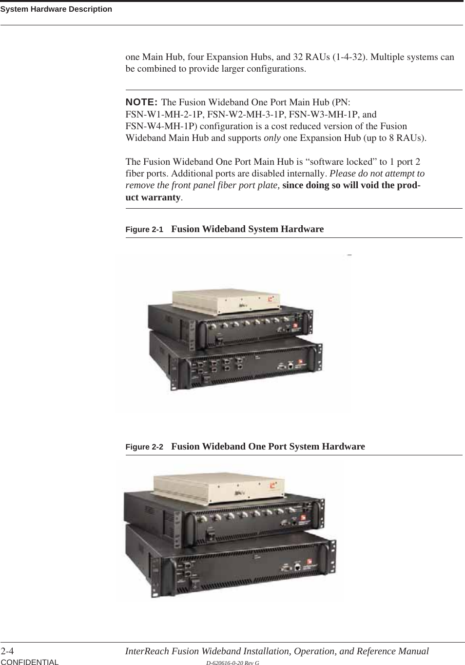
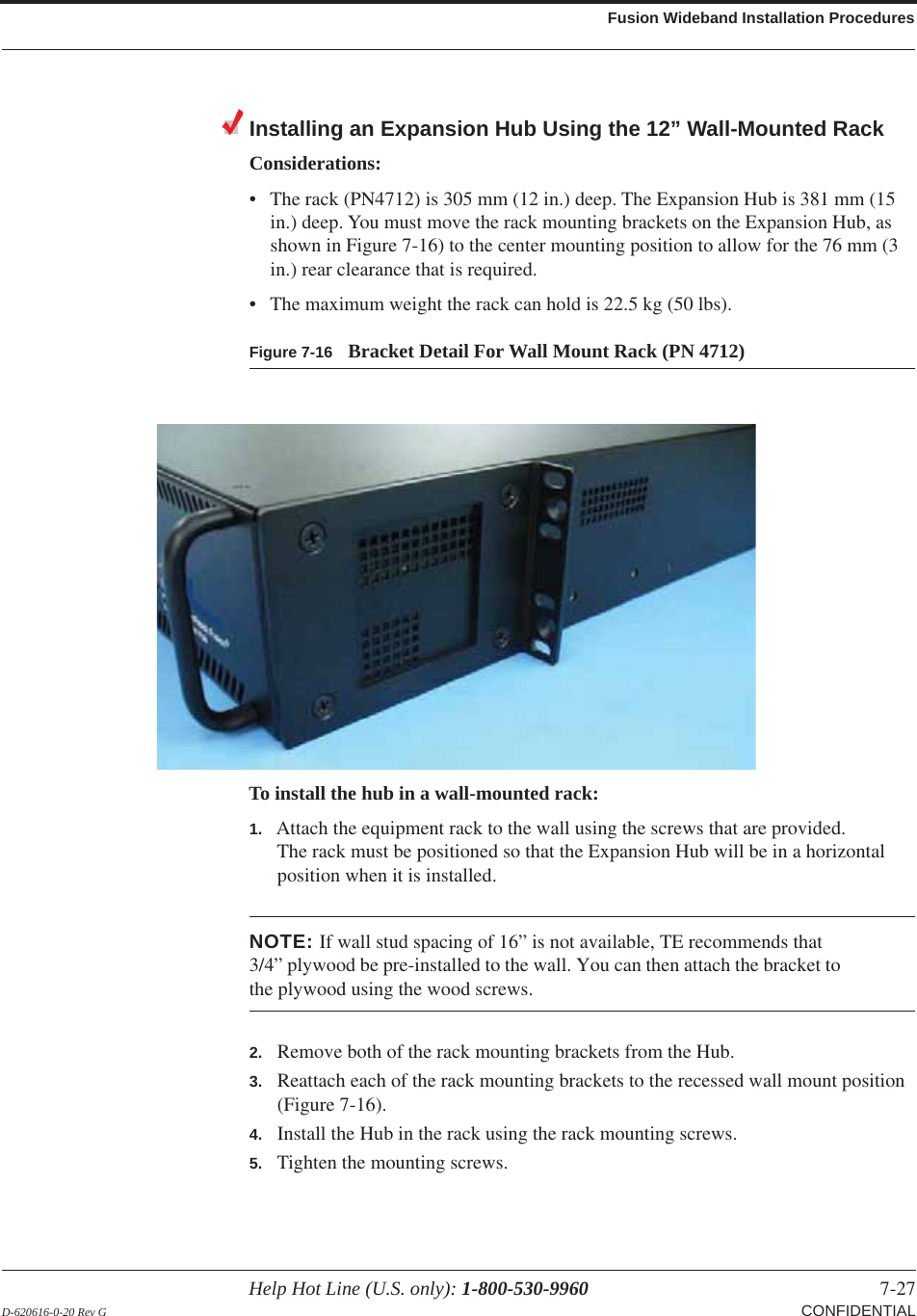
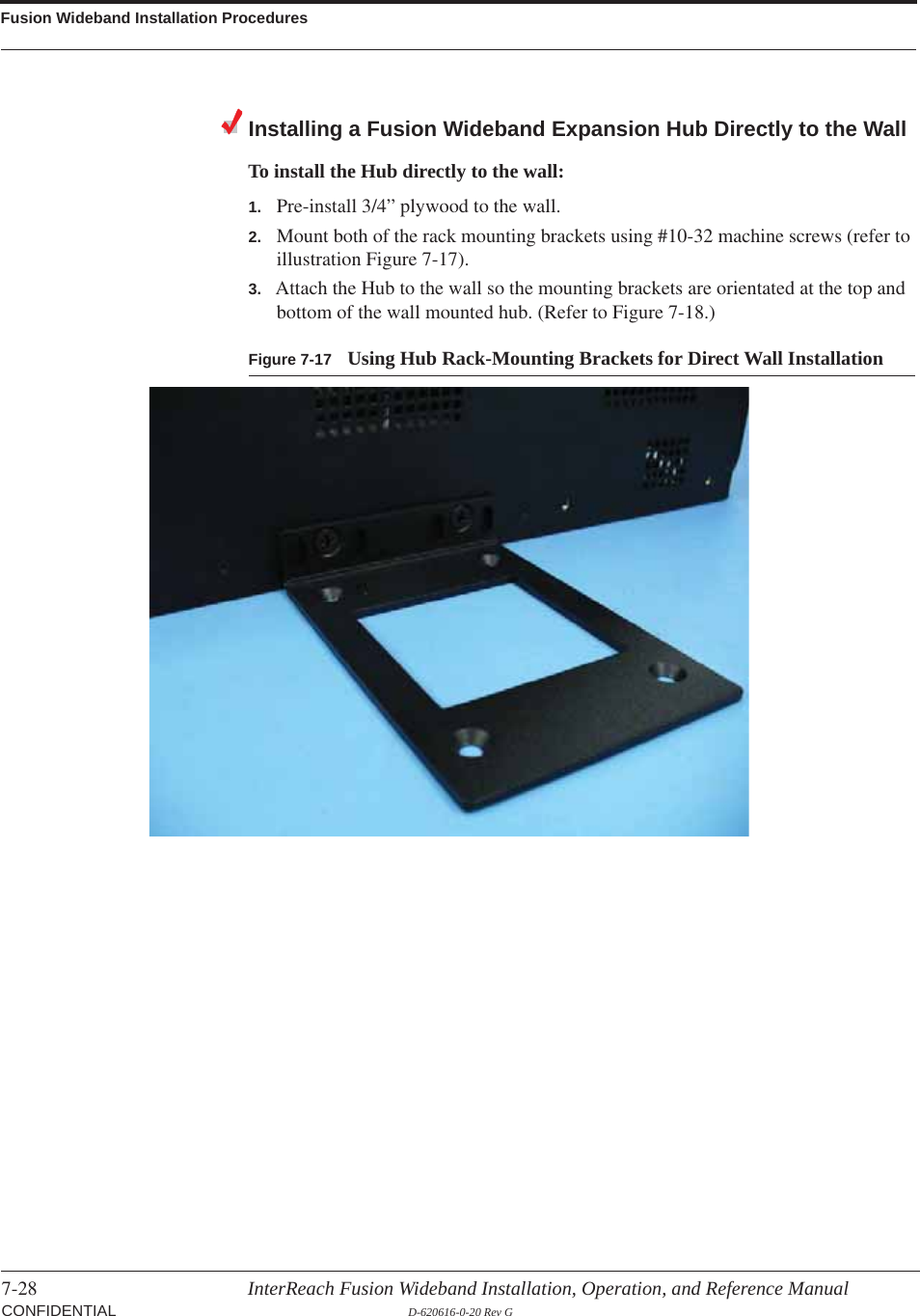
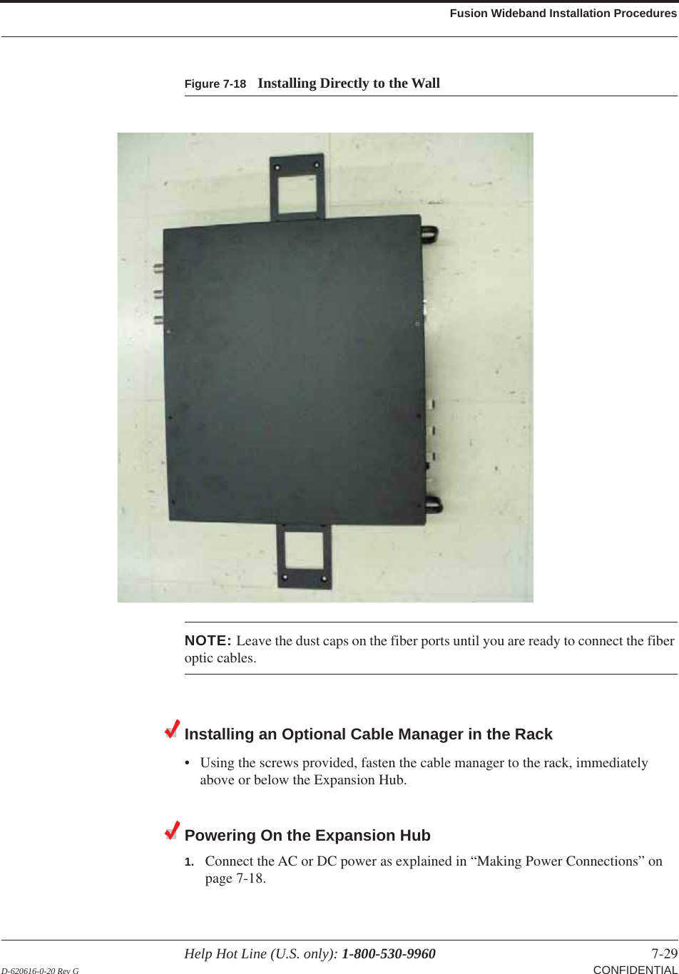
ADC Telecommunications F0699-011 InterReach Fusion® 700 MHz (Lower ABC), AWSMIMO HP User Manual
ADC Telecommunications Inc. InterReach Fusion® 700 MHz (Lower ABC), AWSMIMO HP
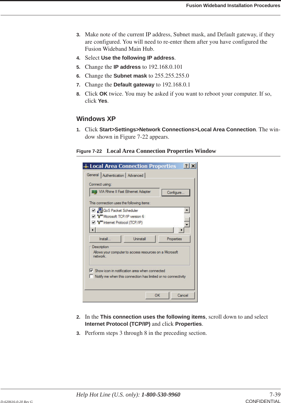
UserManual.wiki
>
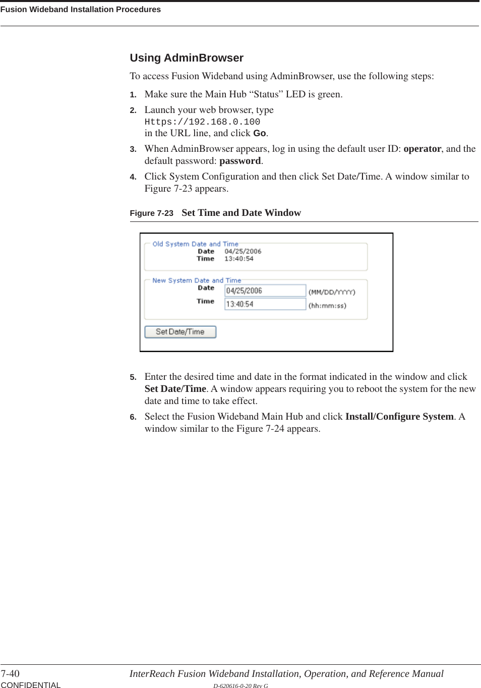
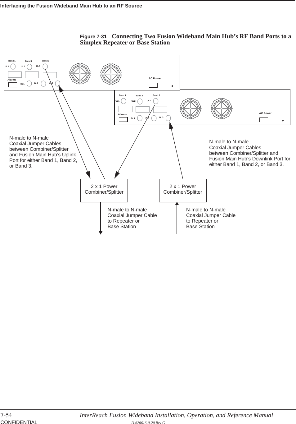
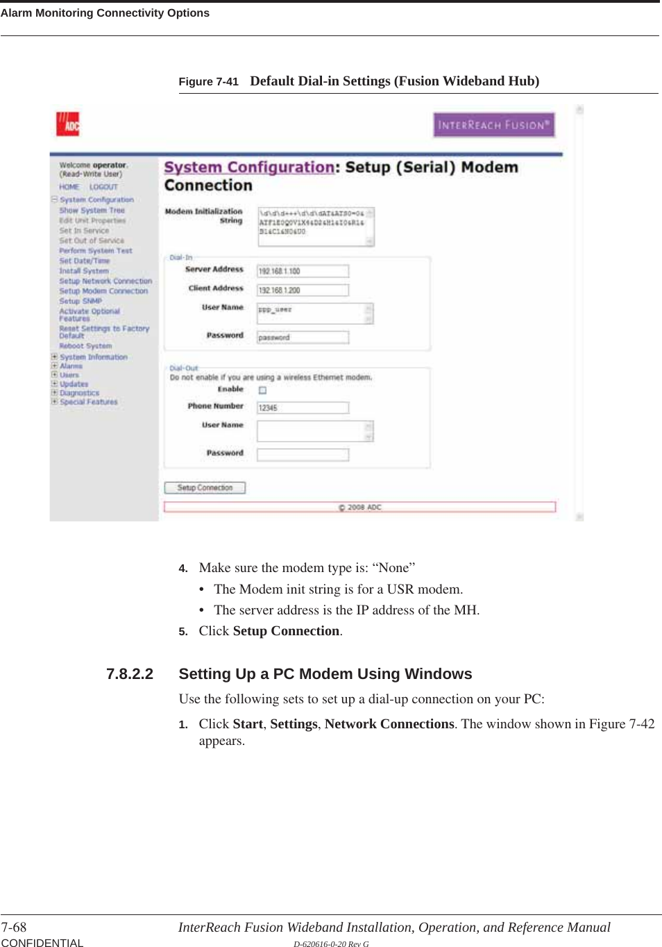
ADC Telecommunications
>
F0699 011 User Manual
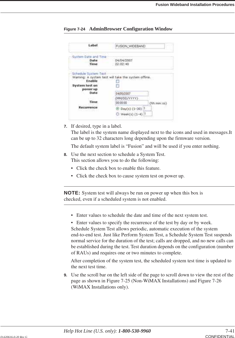
revised manual RE 0.5
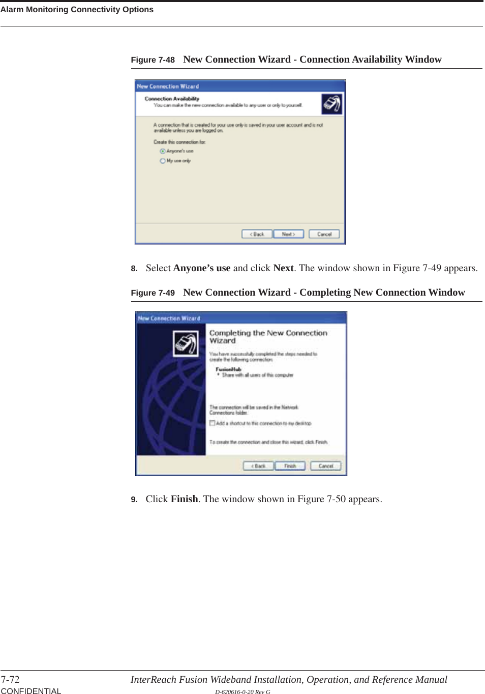
Navigation menu
Upload a User Manual
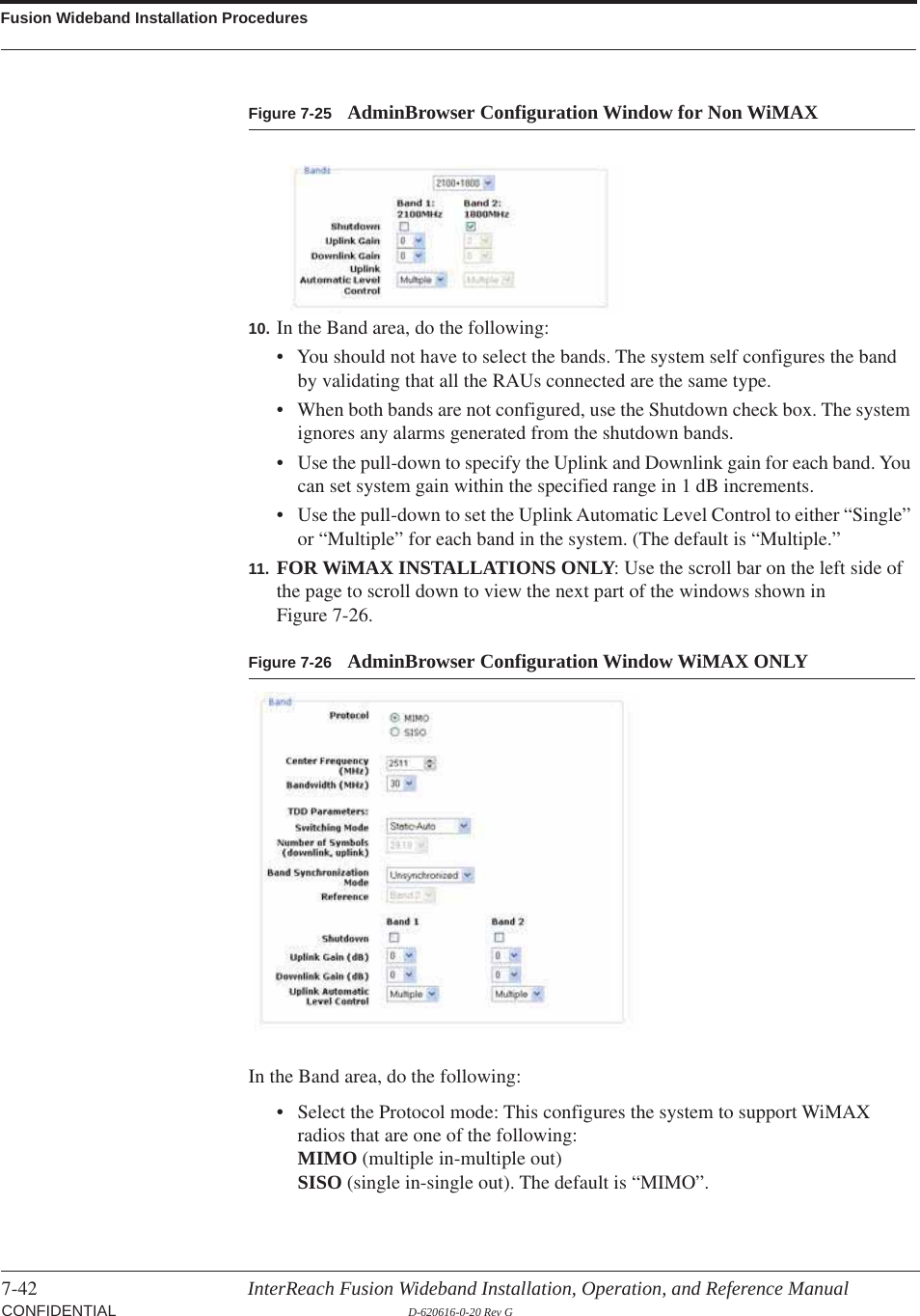
Namespaces
Wiki Guide
HTML
PDF
Info
Views
User Manual
Discussion / Help
Navigation


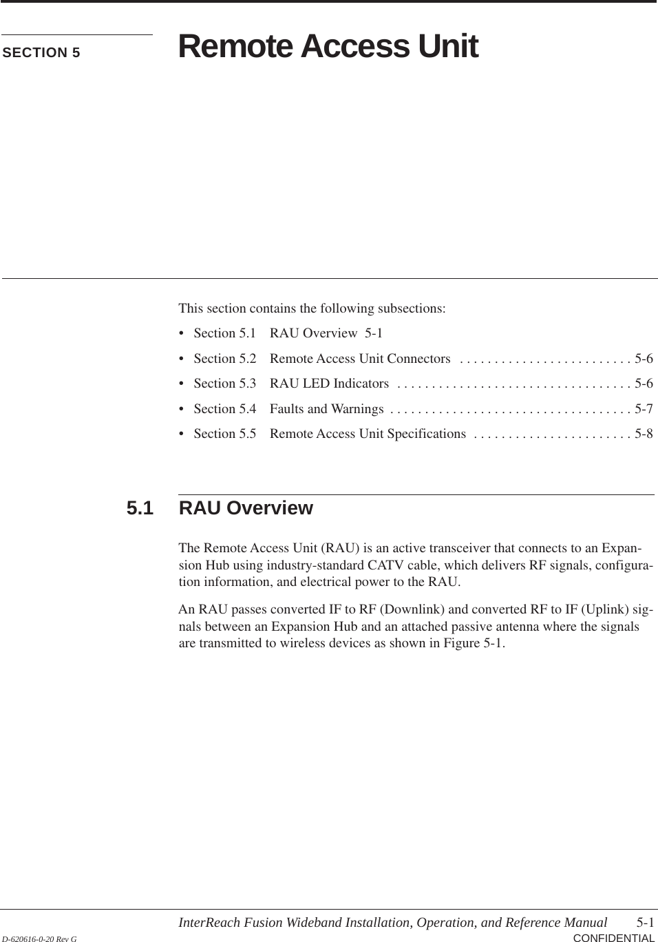
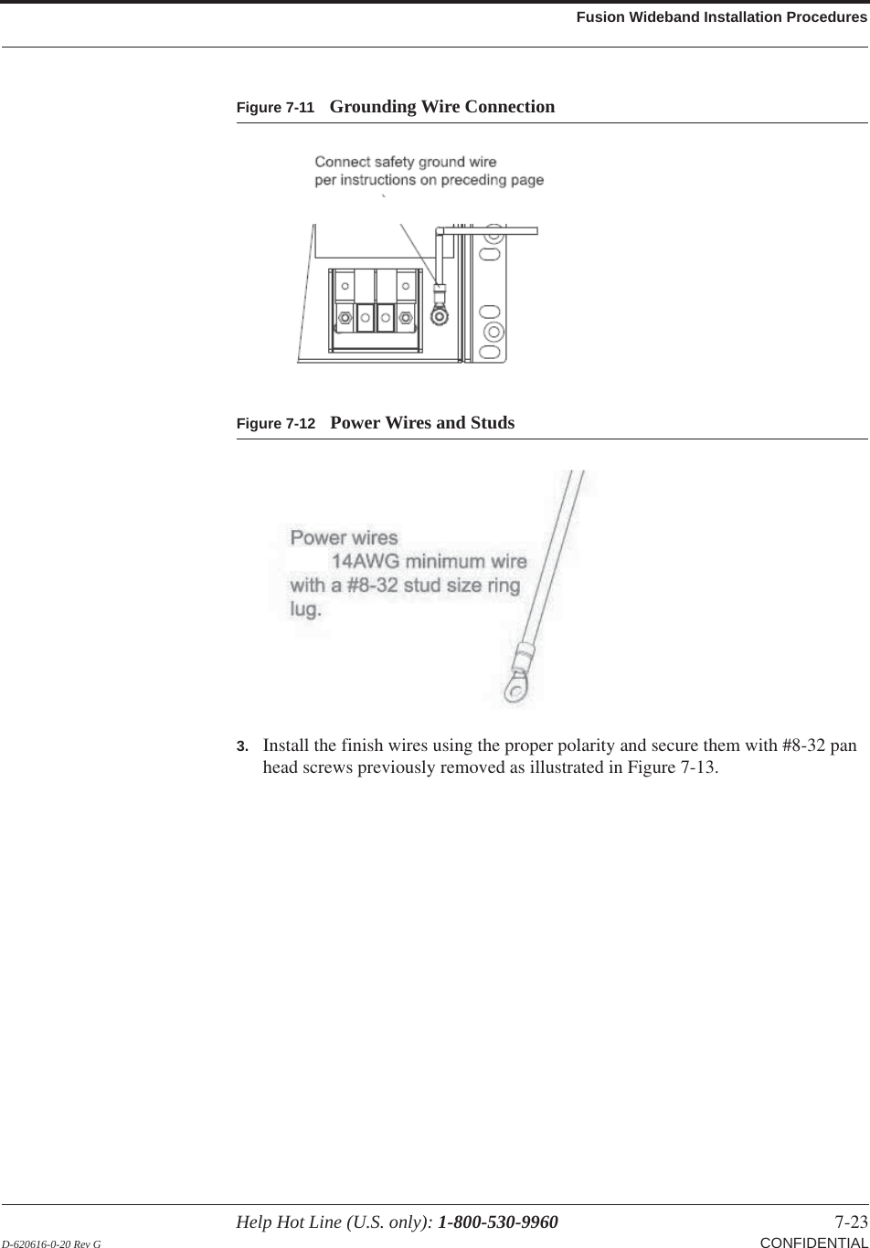
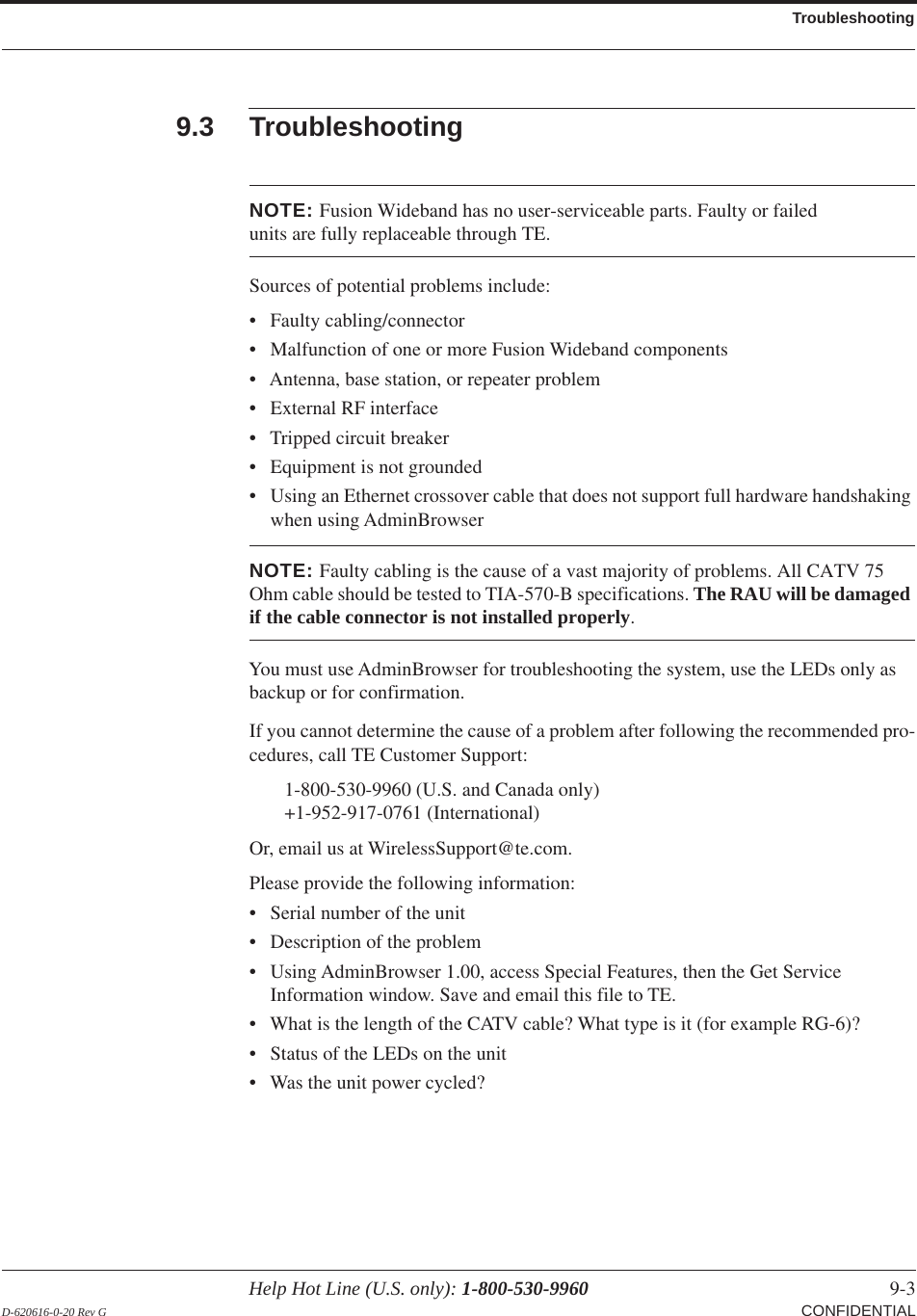
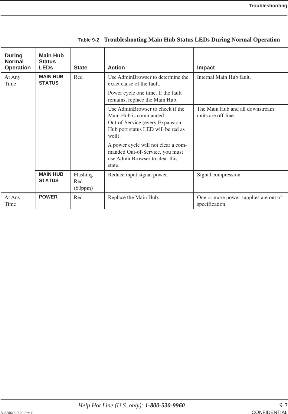
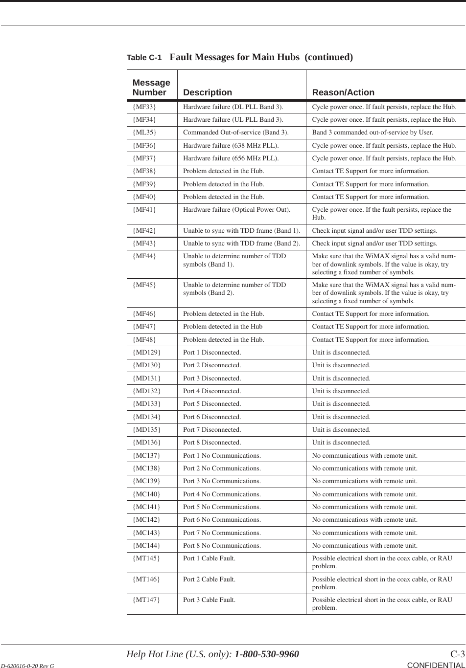
![Help Hot Line (U.S. only): 1-800-530-9960 4-7 D-620616-0-20 Rev G CONFIDENTIALExpansion Hub Front PanelRJ-45 Port LEDsThe Expansion Hub has a port LED, labeled PORT, for each of the eight 75 Ohm, Type F ports. The port LEDs can be in one of the states shown in Table 4-2. These LEDs can be:offsteady greensteady redflashing red (60 pulses per minute [PPM])Table 4-2 Fusion Wideband Expansion Hub Port LED StatesLED State IndicatesOff • The RAU is not connected. Green• The RAU is connected.• No faults from the RAU.Red (60 PPM) • The RAU was disconnected.• The RAU is not communicating.• The RAU port power is tripped.Red (Steady)• The RAU is disconnected.• The RAU is reporting a fault.Green (60-ppm)• The RAU is disconnected.• The RAU is reporting a lockout condition.PORTPORTPORTPORTPORT](https://usermanual.wiki/ADC-Telecommunications/F0699-011/User-Guide-1884358-Page-60.png)


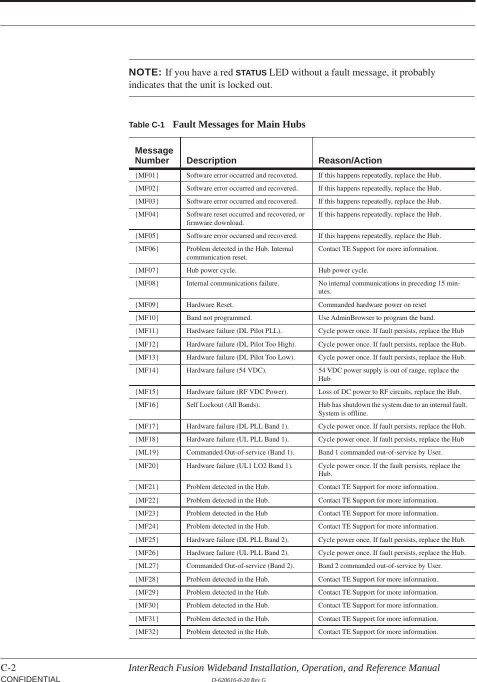
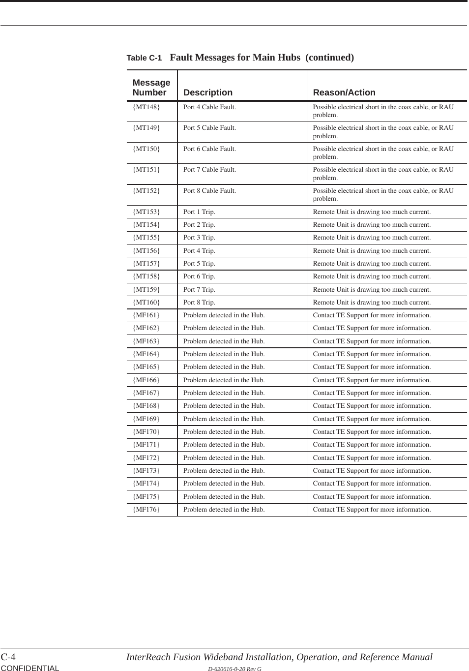
![C-10 InterReach Fusion Wideband Installation, Operation, and Reference Manual CONFIDENTIAL D-620616-0-20 Rev GC.5 Messages for Main HubsWarning MessagesWarnings alert you to conditions that indicate possible service impact. Warnings are displayed in the Messages pane in red lettering.Before addressing warnings, ensure that all faults are resolved. Take appropriate action to resolve the warnings, as indicated in the following tables.NOTE: AdminBrowser v000007 or higher displays events (faults, warn-ings, or status messages) depending on your view preference. To change your view preference, refer to Section 3.5, “Faults, Warnings, and Status Messages” of the Fusion Installation, Operation, and Maintenance Manual.Status MessagesStatus messages alert you to conditions that are important, but generally do not impact service. Status messages alert you to conditions that are important, but gener-ally do not impact service. Status messages are displayed in the Messages pane in blue lettering.NOTE: AdminBrowser v000007 or higher displays events (faults, warn-ings, or status messages) depending on your view preference. To change your view preference, refer to Section 3.5, “Faults, Warnings, and Status Messages” of the Fusion Installation, Operation, and Maintenance Manual.NOTE: The icons displayed in the system status tree assume that there are no other faults, warnings, or status present.In Table C-5, the message number is in the following form:[Mnn]/X where nn equals the message number, and X equals the default of either Sta-tus (S) or Warning (W).](https://usermanual.wiki/ADC-Telecommunications/F0699-011/User-Guide-1884358-Page-235.png)
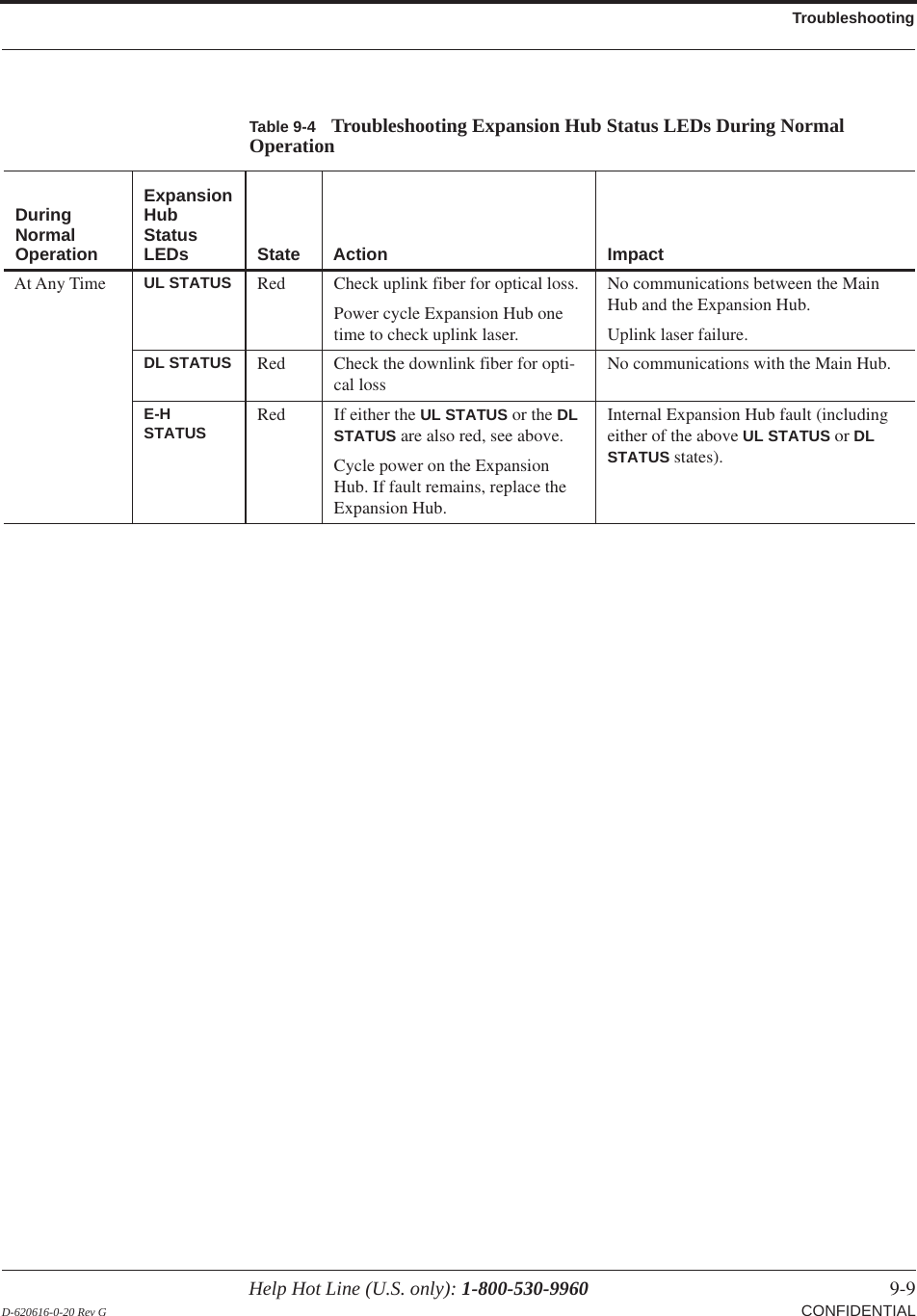
![Help Hot Line (U.S. only): 1-800-530-9960 C-11 D-620616-0-20 Rev G CONFIDENTIALTable C-5 Warnings/Status Messages for Main HubsMessageNumber/Default Description Reason/Action[M01]/S Fan 1 failure. Check the fan for rotation, air flow blockage, and dust. Replace the Hub on high temperature warning.[M02]/S Fan 2 failure. Check the fan for rotation, air flow blockage, and dust. Replace the Hub on high temperature warning.[M03]/S 54 VDC Pwr Supply Fan failure. Check the fan for rotation, air flow blockage, and dust. Replace the Hub on high temperature warning.[M04]/W 5 VDC Monitor. DC power out of range, replace the Hub.[M05]/W 9 VDC Monitor. DC power out of range, replace the Hub.[M06]/W 54 VDC Monitor. DC power out of range, replace the Hub.[M07]/W 3 VDC Monitor. DC power out of range, replace the Hub.[M08]/W 12 VDC Monitor. DC power out of range, replace the Hub.[M09]/W Temperature High. Reduce ambient temperature, check for air flow blockage, fan rotation.[M10]/W -5 VDC Monitor. DC power is out of range, replace the Hub.[M11]/W High laser current. Output laser failure possible, replace the Hub when possi-ble.[M12]/W DL path loss is too high Replace the Hub.[M13]/S Low input optical (Port 1). Check the uplink fiber.[M14]/S Low input optical (Port 2). Check the uplink fiber.[M15]/S Low input optical (Port 3). Check the uplink fiber.[M16]/S Low input optical (Port 4). Check the uplink fiber.[M17]/S Hardware failure (Test Tone PLL Band 1). Unable to perform DL system test.[M18]/S Hardware failure (Test Tone Too High Band 1). Unable to perform DL system test.[M19]/S Hardware failure (Test Tone Too Low Band 1). Unable to perform DL system test.[M20]/W Overdrive limiter active (Band 1). Reduce input signal power to avoid potential component damage.[M21]/W CEMark limiter at maximum (Band 1). Reduce input signal power to avoid drop in system gain.[M22]/W No DL test tone (Band 1). Hub DL gain is low.[M23]/S No UL test tone (Band 1). Hub UL path gain is low.[M24]/S Problem detected in the system. Contact TE Support for more information.[M25]/S Hardware failure (Test Tone PLL Band 2). Unable to perform DL system test. Replace the hub when possible.[M26]/S Hardware failure (Test Tone Too High Band 2). Unable to perform DL system test. Replace the hub when possible.[M27]/S Hardware failure (Test Tone Too Low Band 2). Unable to perform DL system test. Replace the hub when possible.[M28]/W Overdrive limiter active (Band 2). Reduce input signal power to avoid potential component damage.[M29]/W CEMark limiter at maximum (Band 2). Reduce input signal power to avoid drop in system gain.](https://usermanual.wiki/ADC-Telecommunications/F0699-011/User-Guide-1884358-Page-236.png)
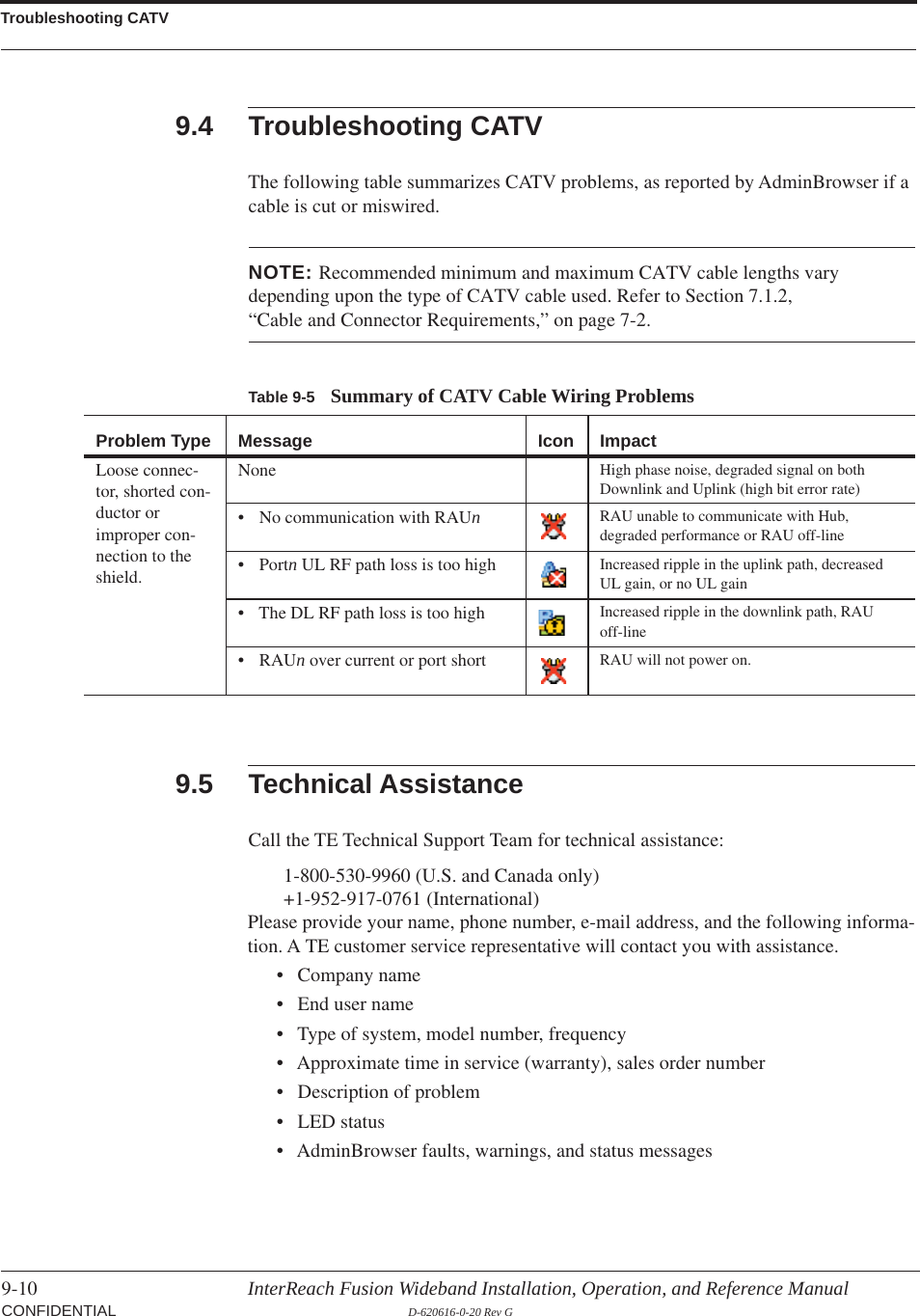
![C-12 InterReach Fusion Wideband Installation, Operation, and Reference Manual CONFIDENTIAL D-620616-0-20 Rev G[M30]/W No DL test tone (Band 2). Hub DL path gain is low.[M31]/S No UL test tone (Band 2). Hub UL path gain is low.[M32]/S Problem detected in the system. Contact TE Support for more information.[M33]/S Hardware failure (Test Tone PLL Band 3). Unable to perform DL system test.[M34]/S Hardware failure (Test Tone Too High Band 3). Unable to perform DL system test.[M35]/S Hardware failure (Test Tone Too Low Band 3). Unable to perform DL system test.[M36]/W Overdrive limiter active (Band 3). Reduce input signal power to avoid potential component damage.[M37]/W CEMark limiter at maximum (Band 3). Reduce input signal power to avoid drop in system gain.[M38]/W No DL test tone (Band 3). Hub DL path gain is low.[M39]/S No UL test tone (Band 3). Hub UL path gain is low.[M40]/S Problem detected in the Hub. Contact TE Support for more information.[M41]/W Port 1 No DL test tone (Band 1). Hub/Port DL path gain is low.[M42]/W Port 2 No DL test tone (Band 1). Hub/Port DL path gain is low.[M43]/W Port 3 No DL test tone (Band 1). Hub/Port DL path gain is low.[M44]/W Port 4 No DL test tone (Band 1). Hub/Port DL path gain is low.[M45]/W Port 5 No DL test tone (Band 1). Hub/Port DL path gain is low.[M46]/W Port 6 No DL test tone (Band 1). Hub/Port DL path gain is low.[M47]/W Port 7 No DL test tone (Band 1). Hub/Port DL path gain is low.[M48]/W Port 8 No DL test tone (Band 1). Hub/Port DL path gain is low.[M49]/W Port 1 No DL test tone (Band 2). Hub/Port DL path gain is low.[M50]/W Port 2 No DL test tone (Band 2). Hub/Port DL path gain is low.[M51]/W Port 3 No DL test tone (Band 2). Hub/Port DL path gain is low.[M52]/W Port 4 No DL test tone (Band 2). Hub/Port DL path gain is low.[M53]/W Port 5 No DL test tone (Band 2). Hub/Port DL path gain is low.[M54]/W Port 6 No DL test tone (Band 2). Hub/Port DL path gain is low.[M55]/W Port 7 No DL test tone (Band 2). Hub/Port DL path gain is low.[M56]/W Port 8 No DL test tone (Band 2). Hub/Port DL path gain is low.[M57]/W Port 1 No DL test tone (Band 3). Hub/Port DL path gain is low.[M58]/W Port 2 No DL test tone (Band 3). Hub/Port DL path gain is low.[M59]/W Port 3 No DL test tone (Band 3). Hub/Port DL path gain is low.[M60]/W Port 4 No DL test tone (Band 3). Hub/Port DL path gain is low.[M61]/W Port 5 No DL test tone (Band 3). Hub/Port DL path gain is low.[M62]/W Port 6 No DL test tone (Band 3). Hub/Port DL path gain is low.[M63]/W Port 7 No DL test tone (Band 3). Hub/Port DL path gain is low.[M64]/W Port 8 No DL test tone (Band 3). Hub/Port DL path gain is low.[M65]/S No UL test tone Port 1 (Band 1). Hub/Port UL path gain is low.Table C-5 Warnings/Status Messages for Main Hubs (continued)MessageNumber/Default Description Reason/Action](https://usermanual.wiki/ADC-Telecommunications/F0699-011/User-Guide-1884358-Page-237.png)
![Help Hot Line (U.S. only): 1-800-530-9960 C-13 D-620616-0-20 Rev G CONFIDENTIAL[M66]/S No UL test tone Port 2 (Band 1). Hub/Port UL path gain is low.[M67]/S No UL test tone Port 3 (Band 1). Hub/Port UL path gain is low.[M68]/S No UL test tone Port 4 (Band 1). Hub/Port UL path gain is low.[M69]/S No UL test tone Port 1 (Band 2). Hub/Port UL path gain is low.[M70]/S No UL test tone Port 2 (Band 2). Hub/Port UL path gain is low.[M71]/S No UL test tone Port 3 (Band 2). Hub/Port UL path gain is low.[M72]/S No UL test tone Port 4 (Band 2). Hub/Port UL path gain is low.[M73]/S No UL test tone Port 1 (Band 3). Hub/Port UL path gain is low.[M74]/S No UL test tone Port 2 (Band 3). Hub/Port UL path gain is low.[M75]/S No UL test tone Port 3 (Band 3). Hub/Port UL path gain is low.[M76]/S No UL test tone Port 4 (Band 3). Hub/Port UL path gain is low.[M77]/S Problem detected in the Hub. Contact TE Support for more information.[M78]/S Problem detected in the Hub. Contact TE Support for more information.[M79]/S Problem detected in the Hub. Contact TE Support for more information.[M80]/S Problem detected in the Hub. Contact TE Support for more information.[M81]/W Port 1 DL path loss is high. If the problem is on more than one port, replace the Hub. Switch the cable connection to a different hub port until the Hub can be replaced.[M82]/W Port 2 DL path loss is high. If the problem is on more than one port, replace the Hub. Switch the cable connection to a different hub port until the Hub can be replaced.[M83]/W Port 3 DL path loss is high. If the problem is on more than one port, replace the Hub. Switch the cable connection to a different hub port until the Hub can be replaced.[M84]/W Port 4 DL path loss is high. If the problem is on more than one port, replace the Hub. Switch the cable connection to a different hub port until the Hub can be replaced.[M85]/W Port 5 DL path loss is high. If the problem is on more than one port, replace the Hub. Switch the cable connection to a different hub port until the Hub can be replaced.[M86]/W Port 6 DL path loss is high. If the problem is on more than one port, replace the Hub. Switch the cable connection to a different hub port until the Hub can be replaced.[M87]/W Port 7 DL path loss is high. If the problem is on more than one port, replace the Hub. Switch the cable connection to a different hub port until the Hub can be replaced.[M88]/W Port 8 DL path loss is high. If the problem is on more than one port, replace the Hub. Switch the cable connection to a different hub port until the Hub can be replaced.[M89]/W Port 1 UL path loss is high. Check the cable for high RF loss. Switch the cable connec-tion to a different hub port. If the problem on more than one port, replace the Hub, otherwise replace the RAU.[M90]/W Port 2 UL path loss is high. Check the cable for high RF loss. Switch the cable connec-tion to a different hub port. If the problem is on more than one port, replace the Hub, otherwise replace the RAU.[M91]/W Port 3 UL path loss is high. Check the cable for high RF loss. Switch the cable connec-tion to a different hub port. If the problem is on more than one port, replace the Hub, otherwise replace the RAU.Table C-5 Warnings/Status Messages for Main Hubs (continued)MessageNumber/Default Description Reason/Action](https://usermanual.wiki/ADC-Telecommunications/F0699-011/User-Guide-1884358-Page-238.png)
![C-14 InterReach Fusion Wideband Installation, Operation, and Reference Manual CONFIDENTIAL D-620616-0-20 Rev G[M92]/W Port 4 UL path loss is high. Check the cable for high RF loss. Switch the cable connec-tion to a different hub port. If the problem is on more than one port, replace the Hub, otherwise replace the RAU.[M93]/W Port 5 UL path loss is high. Check the cable for high RF loss. Switch the cable connec-tion to a different hub port. If the problem is on more than one port, replace the Hub, otherwise replace the RAU.[M94]/W Port 6 UL path loss is high. Check the cable for high RF loss. Switch the cable connec-tion to a different hub port. If the problem is on more than one port, replace the Hub, otherwise replace the RAU.[M95]/W Port 7 UL path loss is high. Check the cable for high RF loss. Switch the cable connec-tion to a different hub port. If the problem is on more than one port, replace the Hub, otherwise replace the RAU.[M96]/W Port 8 UL path loss is high. Check the cable for high RF loss. Switch the cable connec-tion to a different hub port. If the problem is on more than one port, replace the Hub, otherwise replace the RAU.[M97]/W Port 1 UL path exceeds maximum gain. If the problem is common to more than one port, replace the Hub, otherwise check the RAU.[M98]/W Port 2 UL path exceeds maximum gain. If the problem is common to more than one port, replace the Hub, otherwise check the RAU.[M99]/W Port 2 UL path exceeds maximum gain. If the problem is common to more than one port, replace the Hub, otherwise check the RAU.[M100]/W Port 2 UL path exceeds maximum gain. If the problem is common to more than one port, replace the Hub, otherwise check the RAU.[M101]/W Port 2 UL path exceeds maximum gain. If the problem is common to more than one port, replace the Hub, otherwise check the RAU.[M102]/W Port 2 UL path exceeds maximum gain. If the problem is common to more than one port, replace the Hub, otherwise check the RAU.[M103]/W Port 2 UL path exceeds maximum gain. If the problem is common to more than one port, replace the Hub, otherwise check the RAU.[M104]/W Port 8 UL path exceeds maximum gain. If the problem is common to more than one port, replace the Hub, otherwise check the RAU.[M105]/W Port 1 54 VDC Power Enabled. Caution: Port 54 VDC power may be present at the output.[M106]/W Port 2 54 VDC Power Enabled. Caution: Port 54 VDC power may be present at the output.[M107]/W Port 3 54 VDC Power Enabled. Caution: Port 54 VDC power may be present at the output.[M108]/W Port 4 54 VDC Power Enabled. Caution: Port 54 VDC power may be present at the output.[M109]/W Port 5 54 VDC Power Enabled. Caution: Port 54 VDC power may be present at the output.[M110]/W Port 6 54 VDC Power Enabled. Caution: Port 54 VDC power may be present at the output.[M111]/W Port 7 54 VDC Power Enabled. Caution: Port 54 VDC power may be present at the output.[M112]/W Port 8 54 VDC Power Enabled. Caution: Port 54 VDC power may be present at the output.[M113)/S Port 1 UL Pilot Invalid Enable. Check all downstream units for uplink pilot control.[M114)/S Port 2 UL Pilot Invalid Enable. Check all downstream units for uplink pilot control.[M115)/S Port 3 UL Pilot Invalid Enable. Check all downstream units for uplink pilot control.[M116)/S Port 4 UL Pilot Invalid Enable. Check all downstream units for uplink pilot control.[M117)/S Port 5 UL Pilot Invalid Enable. Check all downstream units for uplink pilot control.[M118)/S Port 6 UL Pilot Invalid Enable. Check all downstream units for uplink pilot control.[M119)/S Port 7 UL Pilot Invalid Enable. Check all downstream units for uplink pilot control.Table C-5 Warnings/Status Messages for Main Hubs (continued)MessageNumber/Default Description Reason/Action](https://usermanual.wiki/ADC-Telecommunications/F0699-011/User-Guide-1884358-Page-239.png)
![Help Hot Line (U.S. only): 1-800-530-9960 C-15 D-620616-0-20 Rev G CONFIDENTIALC.6 Messages for System CPUsIn Table C-6, the message number is in the following form:[Snn]/X where nn equals the message number, and X equals the default of either Sta-tus (S) or Warning (W).Table C-6 Warning/Status Messages for System CPUsMessageNumber/Default Description Reason/Action[S01]/W Alarm Input 1. Check equipment connected to alarm input 1.[S02]/W Alarm Input 2. Check equipment connected to alarm input 2.[S03]/W Alarm Input 3. Check equipment connected to alarm input 3.[S04]/S Performed System Test System has just performed system test.[S05]/S Problem detected in the System CPU. Contact TE Support for more information.[S06]/S Loaded default etb file. Contact TE Support for more information.[S07]/S Loaded default SBC status file. Contact TE Support for more information.[S08]/S Problem detected in the System CPU. Contact TE Support for more information.[S09]/S TTL is full. Retrieve the TTL and erase.[S10]/S Problem detected in the System CPU. Contact TE Support for more information.[S11]/S Problem detected in the System CPU. Contact TE Support for more information.[S12]/S Loaded default Password file. Contact TE Support for more information.[S13]/S Loaded default sys config file. Contact TE Support for more information.[S14]/S Communication retries exceeded. Attempted command three times without response.[S15]/S Problem detected in the System CPU. Contact TE Support for more information.[S16]/S Problem detected in the System CPU. Contact TE Support for more information.[M120)/S Port 8 UL Pilot Invalid Enable. Check all downstream units for uplink pilot control.[M121)/S 3.3 VDC Monitor. Possible 3.3 VDC failure.[M122)/W TDD signaling tone outside valid range (Band 1). Replace the Hub.[M123)/W TDD signaling tone outside valid range (Band 2). Replace the Hub.Table C-5 Warnings/Status Messages for Main Hubs (continued)MessageNumber/Default Description Reason/Action](https://usermanual.wiki/ADC-Telecommunications/F0699-011/User-Guide-1884358-Page-240.png)
![C-16 InterReach Fusion Wideband Installation, Operation, and Reference Manual CONFIDENTIAL D-620616-0-20 Rev GC.7 Messages for Expansion HubsTable C-7 Warning/Status Message for Expansion Hubs MessageNumber/Default Description Reason/Action[E01]/W Alarm Input 1. Check the equipment connected to alarm input 1.[E02]/W Alarm Input 2. Check the equipment connected to alarm input 2.[E03]/W Alarm Input 3. Check the equipment connected to alarm input 3.[E04]/S Problem detected in the EH. Contact TE Support for more information.[E05]/W SNMP Trap #1. TBD.[E06]/W SNMP Trap #2. TBD.[E07]/W SNMP Trap #3. TBD.[E08]/S Problem detected in the EH. Contact TE Support for more information.[E09]/S Fan 1 failure. Check the fan for proper rotation, air flow blockage, and dust accumulation. Replace the Hub on high temperature warning.[E10]/S Fan 2 failure. Check the fan for proper rotation, air flow blockage, and dust accumulation. Replace the Hub on high temperature warning.[E11]/W -5 VDC Monitor. DC power out of range, replace the Hub.[E12]/W 5 VDC Monitor. DC power out of range, replace the Hub.[E13]/W 9 VDC Monitor. DC power out of range, replace the Hub.[E14]/W 54 VDC Pwr Supply failure. DC port power supply out of range, replace the Hub.[E15]/W 3 VDC Monitor. DC power out of range, replace the Hub.[E16]/W 12 VDC Monitor. DC power out of range, replace the Hub.[E17]/W Temperature High. Reduce the ambient temperature, check for air flow blockage, fan rotation.[E18]/W DL path exceeds maximum gain. If the problem is common to more than one port, replace the MH, otherwise check the EH.[E19]/W DL path loss is high. Check the cable for high RF loss. Switch the cable connec-tion to a different MH port. If the problem is on more than one port, replace the EH, otherwise replace the RAU.[E20]/W Hardware Failure (High UL Pilot). Cycle power once. If the fault persists, replace the EH.[E21]/W Hardware Failure (Low UL Pilot). Cycle power once. If the fault persists, replace the EH.[E22]/W Low optical input power. Check the downlink fiber connection.[E23]/W High laser current. Contact TE Support for more information.[E24]/S Problem detected in the EH. Contact TE Support for more information.[E25]/W Port 1 No DL test tone (Band 1). Hub/Port DL path gain is low.[E26]/W Port 2 No DL test tone (Band 1). Hub/Port DL path gain is low.[E27]/W Port 3 No DL test tone (Band 1). Hub/Port DL path gain is low.[E28]/W Port 4 No DL test tone (Band 1). Hub/Port DL path gain is low.[E29]/W Port 5 No DL test tone (Band 1). Hub/Port DL path gain is low.[E30]/W Port 6 No DL test tone (Band 1). Hub/Port DL path gain is low.[E31]/W Port 7 No DL test tone (Band 1). Hub/Port DL path gain is low.[E32]/W Port 8 No DL test tone (Band 1). Hub/Port DL path gain is low.](https://usermanual.wiki/ADC-Telecommunications/F0699-011/User-Guide-1884358-Page-241.png)
![Help Hot Line (U.S. only): 1-800-530-9960 C-17 D-620616-0-20 Rev G CONFIDENTIAL[E33]/W Port 1 No DL test tone (Band 2). Hub/Port DL path gain is low.[E34]/W Port 2 No DL test tone (Band 2). Hub/Port DL path gain is low.[E35]/W Port 3 No DL test tone (Band 2). Hub/Port DL path gain is low.[E36]/W Port 4 No DL test tone (Band 2). Hub/Port DL path gain is low.[E37]/W Port 5 No DL test tone (Band 2). Hub/Port DL path gain is low.[E38]/W Port 6 No DL test tone (Band 2). Hub/Port DL path gain is low.[E39]/W Port 7 No DL test tone (Band 2). Hub/Port DL path gain is low.[E40]/W Port 8 No DL test tone (Band 2). Hub/Port DL path gain is low.[E41]/W Port 1 No DL test tone (Band 3). Hub/Port DL path gain is low.[E42]/W Port 2 No DL test tone (Band 3). Hub/Port DL path gain is low.[E43]/W Port 3 No DL test tone (Band 3). Hub/Port DL path gain is low.[E44]/W Port 4 No DL test tone (Band 3). Hub/Port DL path gain is low.[E45]/W Port 5 No DL test tone (Band 3). Hub/Port DL path gain is low.[E46]/W Port 6 No DL test tone (Band 3). Hub/Port DL path gain is low.[E47]/W Port 7 No DL test tone (Band 3). Hub/Port DL path gain is low.[E48]/W Port 8 No DL test tone (Band 3). Hub/Port DL path gain is low.[E49]/W Port 1 DL path loss is high. If the problem is on more than one port, replace the Hub. Switch the cable connection to a different hub port until the Hub can be replaced.[E50]/W Port 2 DL path loss is high. If the problem is on more than one port, replace the Hub. Switch the cable connection to a different hub port until the Hub can be replaced.[E51]/W Port 3 DL path loss is high. If the problem is on more than one port, replace the Hub. Switch the cable connection to a different hub port until the Hub can be replaced.[E52]/W Port 4 DL path loss is high. If the problem is on more than one port, replace the Hub. Switch the cable connection to a different hub port until the Hub can be replaced.[E53]/W Port 5 DL path loss is high. If the problem is on more than one port, replace the Hub. Switch the cable connection to a different hub port until the Hub can be replaced.[E54]/W Port 6 DL path loss is high. If the problem is on more than one port, replace the Hub. Switch the cable connection to a different hub port until the Hub can be replaced.[E55]/W Port 7 DL path loss is high. If the problem is on more than one port, replace the Hub. Switch the cable connection to a different hub port until the Hub can be replaced.[E56]/W Port 8 DL path loss is high. If the problem is on more than one port, replace the Hub. Switch the cable connection to a different hub port until the Hub can be replaced.[E57]/W Port 1 UL path loss is high. Check the cable for high RF loss. Switch the cable connec-tion to a different hub port. If the problem is on more than one port, replace the Hub, otherwise replace the RAU.[E58]/W Port 2 UL path loss is high. Check the cable for high RF loss. Switch the cable connec-tion to a different hub port. If the problem is on more than one port, replace the Hub, otherwise replace the RAU.Table C-7 Warning/Status Message for Expansion Hubs (continued)MessageNumber/Default Description Reason/Action](https://usermanual.wiki/ADC-Telecommunications/F0699-011/User-Guide-1884358-Page-242.png)
![C-18 InterReach Fusion Wideband Installation, Operation, and Reference Manual CONFIDENTIAL D-620616-0-20 Rev G[E59]/W Port 3 UL path loss is high. Check the cable for high RF loss. Switch the cable connec-tion to a different hub port. If the problem is on more than one port, replace the Hub, otherwise replace the RAU.[E60]/W Port 4 UL path loss is high. Check the cable for high RF loss. Switch the cable connec-tion to a different hub port. If the problem is on more than one port, replace the Hub, otherwise replace the RAU.[E61]/W Port 5 UL path loss is high. Check the cable for high RF loss. Switch the cable connec-tion to a different hub port. If the problem is on more than one port, replace the Hub, otherwise replace the RAU.[E62]/W Port 6 UL path loss is high. Check the cable for high RF loss. Switch the cable connec-tion to a different hub port. If the problem is on more than one port, replace the Hub, otherwise replace the RAU.[E63]/W Port 7 UL path loss is high. Check the cable for high RF loss. Switch the cable connec-tion to a different hub port. If the problem is on more than one port, replace the Hub, otherwise replace the RAU.[E64]/W Port 8 UL path loss is high. Check the cable for high RF loss. Switch the cable connec-tion to a different hub port. If the problem is on more than one port, replace the Hub, otherwise replace the RAU.[E65]/W Port 1 UL path exceeds maxi-mum gain. If the problem is common to more than one port, replace the Hub, otherwise check RAU.[E66]/W Port 2 UL path exceeds maxi-mum gain. If the problem is common to more than one port, replace the Hub, otherwise check RAU.[E67]/W Port 3 UL path exceeds maxi-mum gain. If the problem is common to more than one port, replace the Hub, otherwise check RAU.[E68]/W Port 4 UL path exceeds maxi-mum gain. If the problem is common to more than one port, replace the Hub, otherwise check RAU.[E69]/W Port 5 UL path exceeds maxi-mum gain. If the problem is common to more than one port, replace the Hub, otherwise check RAU.[E70]/W Port 6 UL path exceeds maxi-mum gain. If the problem is common to more than one port, replace the Hub, otherwise check RAU.[E71]/W Port 7 UL path exceeds maxi-mum gain. If problem is common to more than one port, replace the Hub, otherwise check RAU.[E72]/W Port 8 UL path exceeds maxi-mum gain. If the problem is common to more than one port, replace the Hub, otherwise check RAU.[E73]/W Port 1 54 VDC Power Enabled. Caution: Port 54 VDC power may be present at the output.[E74]/W Port 2 54 VDC Power Enabled. Caution: Port 54 VDC power may be present at the output.[E75]/W Port 3 54 VDC Power Enabled. Caution: Port 54 VDC power may be present at the output.[E76]/W Port 4 54 VDC Power Enabled. Caution: Port 54 VDC power may be present at the output.[E77]/W Port 5 54 VDC Power Enabled. Caution: Port 54 VDC power may be present at the output.[E78]/W Port 6 54 VDC Power Enabled. Caution: Port 54 VDC power may be present at the output.[E79]/W Port 7 54 VDC Power Enabled. Caution: Port 54 VDC power may be present at the output.[E80]/W Port 8 54 VDC Power Enabled. Caution: Port 54 VDC power may be present at the output.Table C-7 Warning/Status Message for Expansion Hubs (continued)MessageNumber/Default Description Reason/Action](https://usermanual.wiki/ADC-Telecommunications/F0699-011/User-Guide-1884358-Page-243.png)
![Help Hot Line (U.S. only): 1-800-530-9960 C-19 D-620616-0-20 Rev G CONFIDENTIALC.8 Messages for RAUsIn Table C-8, the message number is in the following form:[Rnn]/X where nn equals the message number, and X equals the default of either Sta-tus (S) or Warning (W).Table C-8 Warning/Status Messages for RAUsMessageNumberDefault Description Reason/Action[R01]/W Temperature High. Check RAU location for excessive temperature; check for air flow blockage and/or incorrect installation. Move the RAU to a cooler environment.[R02]/W No communications from Hub. Check the cable for high RF loss. Switch the cable connec-tion to a different hub port. If the problem persists, replace the RAU.[R03]/W DL RF path loss is too high. Check the cable for high RF loss. Switch the cable connec-tion to a different hub port. If the problem persists, replace the RAU.[R04]/W DL RF path exceeds maximum gain. Check the Hub for proper operation; switch the cable con-nection to a different hub port. If the problem persists, replace the RAU.[R05]/S DL RF path problem (Band 1). Unable to complete the DL system end-to-end test, replace the RAU when possible.[R06]/S DL RF path problem (Band 2). Unable to complete the DL system end-to-end test, replace the RAU when possible.[R07]/S DL RF path problem (Band 3). Unable to complete the DL system end-to-end test, replace the RAU when possible.[R08]/S System test required. Run system test.[R09]/W Antenna Disconnected. Check RAU antenna connection; re-run system test.[R10]/S UL RF path problem (Band 1). Unable to complete the UL system end-to-end test, replace the RAU when possible.[R11]/S UL RF path problem (Band 2). Unable to complete the UL system end-to-end test, replace the RAU when possible.[R12]/S UL RF path problem (Band 3). Unable to complete the UL system end-to-end test, replace the RAU when possible.[R13]/S Problem detected in the RAU. Contact TE Support for more information.[R14]/S Problem detected in the RAU. Contact TE Support for more information.[R15]/S Problem detected in the RAU. Contact TE Support for more information.[R16]/S Problem detected in the RAU. Contact TE Support for more information.[R17]/S Antenna disconnected (Band 1). Check the RAU Band 1 antenna, then rerun the system test.[R18]/S Antenna disconnected (Band 2). Check the RAU Band 2 antenna, then rerun the system test.[R19]/S Hardware Failure (UL FD PLL Band 1). Unable to complete a UL system end-to-end test. Replace the RAU when possible.[R20]/W TDD signaling tone outside valid range (Band 1). If the Main Hub and Expansion Hub are okay, replace the RAU.[R21]/W TDD signaling tone outside valid range (Band 2). If the Main Hub and Expansion Hub are okay, replace the RAU.](https://usermanual.wiki/ADC-Telecommunications/F0699-011/User-Guide-1884358-Page-244.png)
![C-20 InterReach Fusion Wideband Installation, Operation, and Reference Manual CONFIDENTIAL D-620616-0-20 Rev G[R22]/S High PA current (Band 1). The unit is operating with reduced gain. Verify that the input signal is at the appropriate level. If the problem per-sists, replace the RAU when possible.[R23]/S High PA current (Band 2). The unit is operating with reduced gain. Verify that the input signal is at the appropriate level. If the problem per-sists, replace the RAU when possible.Table C-8 Warning/Status Messages for RAUs (continued)MessageNumberDefault Description Reason/Action](https://usermanual.wiki/ADC-Telecommunications/F0699-011/User-Guide-1884358-Page-245.png)