ADC Telecommunications F0699-011 InterReach Fusion® 700 MHz (Lower ABC), AWSMIMO HP User Manual
ADC Telecommunications Inc. InterReach Fusion® 700 MHz (Lower ABC), AWSMIMO HP
revised manual RE 0.5
ADCP-77-044 x Issue 6 x November 2012
D-620616-0-20 Rev G
InterReach Fusion® Wideband
Installation, Operation, and Reference Manual

COPYRIGHT
© 2012, TE Connectivity
All Rights Reserved
REVISION HISTORY
ISSUE DATE REASON FOR CHANGE
1 7/2008 First release
2 10/2008 Add Fusion Wideband 1900/AWS product content
3 8/2009 Add Fusion Wideband 700/AWS and 700 MIMO product content
4 5/2010 Add Fusion Wideband 700 (Lower ABC) MIMO product content
5 9/2011 Add Fusion Wideband 2600 MIMO product content
6 11/2012 Add Fusion Wideband 700 ABC/AWS HP/AWS HP and Fusion Wideband 700 UC/AWS HP/AWS HP
product content
LIST OF CHANGES
The technical changes incorporated into this issue are listed below.
PAGE IDENTIFIER DESCRIPTION OF CHANGE
Add Fusion Wideband 700 ABC/AWS HP/AWS HP and Fusion Wideband 700 UC/AWS HP/AWS
HP product content
TRADEMARK INFORMATION
TE is a registered trademark and InterReach, InterReach Unison, InterReach Fusion, WAVEXchange, FlexWave are registered
trademarks and trademarks of TE Connectivity. All other products, company names, service marks, and trademarks mentioned in
this document or website are used for identification purposes only and may be owned by other companies.
DISCLAIMER OF LIABILITY
Contents herein are current as of the date of publication. TE reserves the right to change the contents without prior notice. In no
event shall TE be liable for any damages resulting from loss of data, loss of use, or loss of profits and TE further disclaims
any and all liability for indirect, incidental, special, consequential or other similar damages. This disclaimer of liability
applies to all products, publications and services during and after the warranty period.
This publication may be verified at any time by contacting TE’s Technical Support Team at 1-800-530-9960 (in U.S.A. or Canada)
or +1-952-917-0761 (outside U.S.A. and Canada), or visit www.te.com/WirelessSupport.
ADC Telecommunications, Inc.
P.O. Box 1101, Minneapolis, Minnesota 55440-1101
In U.S.A. and Canada: 1-800-366-3891
Outside U.S.A. and Canada: (952) 938-8080
Fax: (952) 917-1717
TE Connectivity
541 E. Trimble Road, San Jose, California 95131-1224 USA
In U.S.A. and Canada: 1-800-530-9960
Outside U.S.A. and Canada: +1-952-917-0761

InterReach Spectrum Expansion Module Group Installation Guide iii
Proprietary text field.

InterReach Fusion Wideband Installation, Operation, and Reference Manual iii
D-620616-0-20 Rev G CONFIDENTIAL
Table of Contents
SECTION 1 General Information . . . . . . . . . . . . . . . . . . . . . . 1-1
1.1 Firmware Release . . . . . . . . . . . . . . . . . . . . . . . . . . . . . . . . . . 1-1
1.2 Purpose and Scope . . . . . . . . . . . . . . . . . . . . . . . . . . . . . . . . . 1-1
1.3 Conventions in this Manual . . . . . . . . . . . . . . . . . . . . . . . . . . 1-2
1.4 Standards Conformance . . . . . . . . . . . . . . . . . . . . . . . . . . . . . 1-3
1.5 Related Publications . . . . . . . . . . . . . . . . . . . . . . . . . . . . . . . . 1-3
SECTION 2 InterReach Fusion Wideband
System Description 2-1
2.1 System Overview . . . . . . . . . . . . . . . . . . . . . . . . . . . . . . . . . . 2-1
2.2 System Hardware Description . . . . . . . . . . . . . . . . . . . . . . . . 2-3
2.3 System OA&M Capabilities Overview . . . . . . . . . . . . . . . . . 2-5
2.3.1 System Monitoring and Reporting . . . . . . . . . . . . . . . . . . . . . 2-6
2.3.2 Using Alarm Contacts . . . . . . . . . . . . . . . . . . . . . . . . . . . . . . . 2-6
2.4 System Connectivity . . . . . . . . . . . . . . . . . . . . . . . . . . . . . . . . 2-7
2.5 System Operation . . . . . . . . . . . . . . . . . . . . . . . . . . . . . . . . . . 2-8
2.6 System Specifications . . . . . . . . . . . . . . . . . . . . . . . . . . . . . . . 2-9
2.6.1 RF End-to-End Performance . . . . . . . . . . . . . . . . . . . . . . . . . 2-12
SECTION 3 Fusion Wideband Main Hub . . . . . . . . . . . . . . . . 3-1
3.1 Fusion Wideband Main Hub Overview . . . . . . . . . . . . . . . . . 3-1
3.2 Fusion Wideband Main Hub Front Panel . . . . . . . . . . . . . . . . 3-4
3.2.1 Optical Fiber Uplink/Downlink Ports . . . . . . . . . . . . . . . . . . . 3-5
3.2.2 Communications RS-232 Serial Connector . . . . . . . . . . . . . . . 3-5
3.2.3 Main Hub LED Indicators . . . . . . . . . . . . . . . . . . . . . . . . . . . . 3-5
3.3 Fusion Wideband Main Hub Rear Panel . . . . . . . . . . . . . . . . 3-8
3.3.1 Fusion Wideband Main Hub Rear Panel Connectors . . . . . . . 3-8
3.3.1.1 9-pin D-sub Connector . . . . . . . . . . . . . . . . . . . . . . . . . 3-8
3.3.1.2 N-type Female Connectors . . . . . . . . . . . . . . . . . . . . . . 3-9
3.4 Main Hub Specifications . . . . . . . . . . . . . . . . . . . . . . . . . . . 3-10

CONFIDENTIAL
iv InterReach Fusion Wideband Installation, Operation, and Reference Manual
D-620616-0-20 Rev G
3.5 Faults, Warnings, and Status Messages . . . . . . . . . . . . . . . . . 3-11
3.5.1 Description . . . . . . . . . . . . . . . . . . . . . . . . . . . . . . . . . . . . . . . 3-11
3.5.2 View Preference . . . . . . . . . . . . . . . . . . . . . . . . . . . . . . . . . . . 3-12
SECTION 4 Fusion Wideband
Expansion Hub 4-1
4.1 Expansion Hub Overview . . . . . . . . . . . . . . . . . . . . . . . . . . . . 4-1
4.2 Expansion Hub Front Panel . . . . . . . . . . . . . . . . . . . . . . . . . . 4-3
4.2.1 75 Ohm Type F Connectors . . . . . . . . . . . . . . . . . . . . . . . . . . . 4-4
4.2.2 Manufacturing RS-232 Serial Connector . . . . . . . . . . . . . . . . . 4-4
4.2.3 Optical Fiber Uplink/Downlink Connectors . . . . . . . . . . . . . . 4-4
4.2.4 LED Indicators . . . . . . . . . . . . . . . . . . . . . . . . . . . . . . . . . . . . . 4-5
4.3 Expansion Hub Rear Panel . . . . . . . . . . . . . . . . . . . . . . . . . . . 4-8
4.4 Faults, Warnings, and Status Messages . . . . . . . . . . . . . . . . . . 4-9
4.5 Expansion Hub Specifications . . . . . . . . . . . . . . . . . . . . . . . 4-10
SECTION 5 Remote Access Unit . . . . . . . . . . . . . . . . . . . . . . 5-1
5.1 RAU Overview . . . . . . . . . . . . . . . . . . . . . . . . . . . . . . . . . . . . 5-1
5.2 Remote Access Unit Connectors . . . . . . . . . . . . . . . . . . . . . . . 5-6
5.2.1 50 Ohm Type-N Connector . . . . . . . . . . . . . . . . . . . . . . . . . . . 5-6
5.2.2 75 Ohm Type-F Connector . . . . . . . . . . . . . . . . . . . . . . . . . . . 5-6
5.3 RAU LED Indicators . . . . . . . . . . . . . . . . . . . . . . . . . . . . . . . 5-6
5.4 Faults and Warnings . . . . . . . . . . . . . . . . . . . . . . . . . . . . . . . . 5-7
5.5 Remote Access Unit Specifications . . . . . . . . . . . . . . . . . . . . 5-8
SECTION 6 Designing a
Fusion Wideband Solution 6-1
6.1 Overview . . . . . . . . . . . . . . . . . . . . . . . . . . . . . . . . . . . . . . . . . 6-1
6.2 Downlink RSSI Design Goal . . . . . . . . . . . . . . . . . . . . . . . . . 6-3
6.3 Maximum Output Power per Carrier . . . . . . . . . . . . . . . . . . . 6-4
6.3.1 700/AWS RAU . . . . . . . . . . . . . . . . . . . . . . . . . . . . . . . . . . . . 6-5
6.3.2 700 MHz (Upper C) MIMO RAU . . . . . . . . . . . . . . . . . . . . . . 6-6
6.3.3 700 MHz (Lower ABC) MIMO RAU . . . . . . . . . . . . . . . . . . . 6-6
6.3.4 700 ABC/AWS HP/AWS HP RAU . . . . . . . . . . . . . . . . . . . . . 6-7
6.3.5 700 UC/AWS HP/AWS HP RAU . . . . . . . . . . . . . . . . . . . . . . 6-8
6.3.6 800 MHz SMR . . . . . . . . . . . . . . . . . . . . . . . . . . . . . . . . . . . . . 6-9
6.3.7 850 MHz Cellular . . . . . . . . . . . . . . . . . . . . . . . . . . . . . . . . . 6-10
6.3.8 1800 MHz DCS . . . . . . . . . . . . . . . . . . . . . . . . . . . . . . . . . . . 6-11
6.3.9 1900 MHz PCS . . . . . . . . . . . . . . . . . . . . . . . . . . . . . . . . . . . 6-12
6.3.10 2100 MHz AWS . . . . . . . . . . . . . . . . . . . . . . . . . . . . . . . . . . . 6-13
6.3.11 2.1 GHz UMTS . . . . . . . . . . . . . . . . . . . . . . . . . . . . . . . . . . . 6-14
6.3.12 2.1 GHz UMTS High Power . . . . . . . . . . . . . . . . . . . . . . . . . 6-14
6.3.13 2500 MHz WiMAX . . . . . . . . . . . . . . . . . . . . . . . . . . . . . . . . 6-14
6.3.14 2600 MHz MIMO RAU . . . . . . . . . . . . . . . . . . . . . . . . . . . . 6-15
6.4 System Gain . . . . . . . . . . . . . . . . . . . . . . . . . . . . . . . . . . . . . 6-16

CONFIDENTIAL
InterReach Fusion Wideband Installation, Operation, and Reference Manual v
D-620616-0-20 Rev G
6.5 Estimating RF Coverage . . . . . . . . . . . . . . . . . . . . . . . . . . . . 6-18
6.5.1 Path Loss Equation . . . . . . . . . . . . . . . . . . . . . . . . . . . . . . . . 6-19
6.5.2 RAU Coverage Distance . . . . . . . . . . . . . . . . . . . . . . . . . . . . 6-20
6.5.3 Examples of Design Estimates . . . . . . . . . . . . . . . . . . . . . . . 6-24
6.6 Link Budget Analysis . . . . . . . . . . . . . . . . . . . . . . . . . . . . . . 6-26
6.6.1 Elements of a Link Budget for Narrowband Standards . . . . . 6-26
6.6.2 Narrowband Link Budget Analysis for a Microcell Application 6-
29
6.6.3 Elements of a Link Budget for CDMA Standards . . . . . . . . . 6-31
6.6.4 CDMA Link Budget Analysis for a Microcell Application . . 6-34
6.6.5 Considerations for Re-Radiation (Over-the-Air) Systems . . 6-37
6.7 Optical Power Budget . . . . . . . . . . . . . . . . . . . . . . . . . . . . . . 6-38
6.8 Connecting a Main Hub to a Base Station . . . . . . . . . . . . . . 6-39
6.8.1 Uplink Attenuation . . . . . . . . . . . . . . . . . . . . . . . . . . . . . . . . 6-39
6.8.2 RAU Attenuation and ALC . . . . . . . . . . . . . . . . . . . . . . . . . . 6-40
6.8.2.1 Using the RAU 10 dB Attenuation Setting . . . . . . . . . 6-41
6.8.2.2 Using the Uplink ALC Setting . . . . . . . . . . . . . . . . . 6-42
SECTION 7 Installing Fusion Wideband . . . . . . . . . . . . . . . . 7-1
7.1 Installation Requirements . . . . . . . . . . . . . . . . . . . . . . . . . . . . 7-1
7.1.1 Component Location Requirements . . . . . . . . . . . . . . . . . . . . 7-2
7.1.2 Cable and Connector Requirements . . . . . . . . . . . . . . . . . . . . 7-2
7.1.3 Distance Requirements . . . . . . . . . . . . . . . . . . . . . . . . . . . . . . 7-3
7.2 Safety Precautions . . . . . . . . . . . . . . . . . . . . . . . . . . . . . . . . . 7-3
7.2.1 Installation Guidelines . . . . . . . . . . . . . . . . . . . . . . . . . . . . . . . 7-3
7.2.2 General Safety Precautions . . . . . . . . . . . . . . . . . . . . . . . . . . . 7-4
7.2.3 Fiber Port Safety Precautions . . . . . . . . . . . . . . . . . . . . . . . . . 7-4
7.3 Preparing for System Installation . . . . . . . . . . . . . . . . . . . . . . 7-6
7.3.1 Pre-Installation Inspection . . . . . . . . . . . . . . . . . . . . . . . . . . . . 7-6
7.3.2 Installation Checklist . . . . . . . . . . . . . . . . . . . . . . . . . . . . . . . . 7-6
7.3.3 Tools and Materials Required . . . . . . . . . . . . . . . . . . . . . . . . . 7-8
7.3.4 Optional Accessories . . . . . . . . . . . . . . . . . . . . . . . . . . . . . . . . 7-9
7.4 Fusion Wideband Installation Procedures . . . . . . . . . . . . . . 7-10
7.4.1 Installing a Fusion Wideband Main Hub . . . . . . . . . . . . . . . . 7-11
7.4.2 Installing Expansion Hubs . . . . . . . . . . . . . . . . . . . . . . . . . . . 7-26
7.4.3 Installing RAUs . . . . . . . . . . . . . . . . . . . . . . . . . . . . . . . . . . . 7-33
7.4.3.1 Troubleshooting Using RAU LEDs During Installation . 7-
36
7.4.4 Configuring the Fusion Wideband System . . . . . . . . . . . . . . 7-37
7.5 Splicing Fiber Optic Cable . . . . . . . . . . . . . . . . . . . . . . . . . . 7-45
7.6 Interfacing the Fusion Wideband Main Hub
to an RF Source 7-47
7.6.1 Connecting a Single Fusion Wideband Main Hub to an RF
Source 7-47
7.6.2 Connecting Multiple Fusion Wideband Main Hubs to an RF
Source 7-52

CONFIDENTIAL
vi InterReach Fusion Wideband Installation, Operation, and Reference Manual
D-620616-0-20 Rev G
7.7 Connecting Contact Alarms to a Fusion Wideband System . 7-58
7.7.1 Alarm Source . . . . . . . . . . . . . . . . . . . . . . . . . . . . . . . . . . . . . 7-59
7.7.2 Alarm Sense . . . . . . . . . . . . . . . . . . . . . . . . . . . . . . . . . . . . . . 7-62
7.7.3 Alarm Cables . . . . . . . . . . . . . . . . . . . . . . . . . . . . . . . . . . . . . 7-64
7.8 Alarm Monitoring Connectivity Options . . . . . . . . . . . . . . . 7-66
7.8.1 Direct Connection . . . . . . . . . . . . . . . . . . . . . . . . . . . . . . . . . 7-66
7.8.2 Modem Connection . . . . . . . . . . . . . . . . . . . . . . . . . . . . . . . . 7-67
7.8.2.1 Setting Up Fusion Wideband Modem (USR Modem) Using
AdminBrowser 7-67
7.8.2.2 Setting Up a PC Modem Using Windows . . . . . . . . . . 7-68
7.8.3 100 BASE-T Port Expander Connection . . . . . . . . . . . . . . . . 7-76
7.8.4 POTS Line Sharing Switch Connection . . . . . . . . . . . . . . . . 7-77
7.8.5 Ethernet RF Modem . . . . . . . . . . . . . . . . . . . . . . . . . . . . . . . . 7-78
7.8.6 Ethernet LAN Connection . . . . . . . . . . . . . . . . . . . . . . . . . . . 7-79
7.8.7 SNMP Interface . . . . . . . . . . . . . . . . . . . . . . . . . . . . . . . . . . . 7-80
SECTION 8 Replacing Fusion Wideband Components . . . . 8-1
8.1 Replacing an RAU . . . . . . . . . . . . . . . . . . . . . . . . . . . . . . . . . 8-1
8.2 Replacing a Fusion Wideband Expansion Hub . . . . . . . . . . . . 8-3
8.3 Replacing a Fusion Wideband Main Hub . . . . . . . . . . . . . . . . 8-4
SECTION 9 Maintenance, Troubleshooting, and Technical
Assistance 9-1
9.1 Service . . . . . . . . . . . . . . . . . . . . . . . . . . . . . . . . . . . . . . . . . . . 9-1
9.2 Maintenance . . . . . . . . . . . . . . . . . . . . . . . . . . . . . . . . . . . . . . 9-2
9.3 Troubleshooting . . . . . . . . . . . . . . . . . . . . . . . . . . . . . . . . . . . 9-3
9.3.1 Troubleshooting Using AdminBrowser . . . . . . . . . . . . . . . . . . 9-4
9.3.1.1 Troubleshooting Recommendations . . . . . . . . . . . . . . . . 9-4
9.3.1.2 Fault/Warning/Status Indications . . . . . . . . . . . . . . . . . . 9-5
9.3.2 Troubleshooting Using LEDs . . . . . . . . . . . . . . . . . . . . . . . . . 9-5
9.4 Troubleshooting CATV . . . . . . . . . . . . . . . . . . . . . . . . . . . . . 9-10
9.5 Technical Assistance . . . . . . . . . . . . . . . . . . . . . . . . . . . . . . . 9-10
APPENDIX A Cables and Connectors . . . . . . . . . . . . . . . . . . . A-1
A.1 75 Ohm CATV Cable . . . . . . . . . . . . . . . . . . . . . . . . . . . . . . .A-1
A.2 Fiber Optical Cables . . . . . . . . . . . . . . . . . . . . . . . . . . . . . . . .A-6
A.3 Coaxial Cable . . . . . . . . . . . . . . . . . . . . . . . . . . . . . . . . . . . . .A-7
A.4 Standard Modem Cable . . . . . . . . . . . . . . . . . . . . . . . . . . . . .A-7
A.5 TCP/IP Cross-over Cable . . . . . . . . . . . . . . . . . . . . . . . . . . . .A-8
A.6 DB-9 to DB-9 Null Modem Cable . . . . . . . . . . . . . . . . . . . . .A-9
APPENDIX B Compliance . . . . . . . . . . . . . . . . . . . . . . . . . . . . . B-1
B.1 Fusion Wideband System Approval Status . . . . . . . . . . . . . . .B-1
B.2 Human Exposure to RF . . . . . . . . . . . . . . . . . . . . . . . . . . . . .B-4

CONFIDENTIAL
InterReach Fusion Wideband Installation, Operation, and Reference Manual vii
D-620616-0-20 Rev G
APPENDIX C Faults, Warnings, Status Tables for Fusion, Fusion
Wideband, Fusion SingleStar A-1
C.1 Faults Reported by Main Hubs . . . . . . . . . . . . . . . . . . . . . . . .A-1
C.2 Faults Reported for System CPU . . . . . . . . . . . . . . . . . . . . . .A-5
C.3 Faults for Expansion Hubs . . . . . . . . . . . . . . . . . . . . . . . . . . .A-6
C.4 Faults for RAUs . . . . . . . . . . . . . . . . . . . . . . . . . . . . . . . . . . .A-9
C.5 Messages for Main Hubs . . . . . . . . . . . . . . . . . . . . . . . . . . .A-10
C.6 Messages for System CPUs . . . . . . . . . . . . . . . . . . . . . . . . .A-15
C.7 Messages for Expansion Hubs . . . . . . . . . . . . . . . . . . . . . . .A-16
C.8 Messages for RAUs . . . . . . . . . . . . . . . . . . . . . . . . . . . . . . .A-19

CONFIDENTIAL
viii InterReach Fusion Wideband Installation, Operation, and Reference Manual
D-620616-0-20 Rev G

InterReach Fusion Wideband Installation, Operation, and Reference Manual -ix
D-620616-0-20 Rev G CONFIDENTIAL
List of Figures
Figure 2-1 Fusion Wideband System Hardware . . . . . . . . . . . . . . . . . . . . . . . . . . . . 4
Figure 2-2 Fusion Wideband One Port System Hardware. . . . . . . . . . . . . . . . . . . . . 4
Figure 2-3 Three Methods for OA&M Communications . . . . . . . . . . . . . . . . . . . . . 5
Figure 2-4 System Monitoring and Reporting . . . . . . . . . . . . . . . . . . . . . . . . . . . . . 6
Figure 2-5 Fusion Wideband’s Double Star Architecture . . . . . . . . . . . . . . . . . . . . . 7
Figure 2-6 Downlink (Base Station to Wireless Devices) . . . . . . . . . . . . . . . . . . . 8
Figure 2-7 Uplink (Wireless Devices to Base Station) . . . . . . . . . . . . . . . . . . . . . . 8
Figure 3-1 Main Hub in a Fusion Wideband System . . . . . . . . . . . . . . . . . . . . . . . . 2
Figure 3-2 Main Hub Block Diagram . . . . . . . . . . . . . . . . . . . . . . . . . . . . . . . . . . . . 3
Figure 3-3 Fusion Wideband Main Hub Front Panel. . . . . . . . . . . . . . . . . . . . . . . . . 4
Figure 3-4 Fusion Wideband Main Hub Rear Panel . . . . . . . . . . . . . . . . . . . . . . . . . 8
Figure 3-5 Preferences Check Boxes. . . . . . . . . . . . . . . . . . . . . . . . . . . . . . . . . . . . 12
Figure 4-1 Expansion Hub in a Fusion Wideband System . . . . . . . . . . . . . . . . . . . . 1
Figure 4-2 Expansion Hub Block Diagram . . . . . . . . . . . . . . . . . . . . . . . . . . . . . . . . 2
Figure 4-3 Expansion Hub Front Panel . . . . . . . . . . . . . . . . . . . . . . . . . . . . . . . . . . . 3
Figure 4-4 Expansion Hub Rear Panel. . . . . . . . . . . . . . . . . . . . . . . . . . . . . . . . . . . . 8
Figure 5-1 Remote Access Unit in a Fusion Wideband System . . . . . . . . . . . . . . . . 2
Figure 5-2 Remote Access Unit Block Diagram (Multiband). . . . . . . . . . . . . . . . . . 2
Figure 6-1 Determining APL between the Antenna and the Wireless Device . . . . 18
Figure 6-2 ALC Operation. . . . . . . . . . . . . . . . . . . . . . . . . . . . . . . . . . . . . . . . . . . . 41
Figure 7-1 Flush Mounting Bracket Detail . . . . . . . . . . . . . . . . . . . . . . . . . . . . . . . 12
Figure 7-2 Bracket Detail For Wall Mount Rack (PN 4712). . . . . . . . . . . . . . . . . . 13
Figure 7-3 Installing Directly to the Wall . . . . . . . . . . . . . . . . . . . . . . . . . . . . . . . . 14
Figure 7-4 Using Hub Rack-Mounting Brackets for Direct Wall Installation. . . . . 15
Figure 7-5 Protective Ground Wire Connection . . . . . . . . . . . . . . . . . . . . . . . . . . . 19
Figure 7-6 DC Terminals. . . . . . . . . . . . . . . . . . . . . . . . . . . . . . . . . . . . . . . . . . . . . 19
Figure 7-7 Power Screw Locations . . . . . . . . . . . . . . . . . . . . . . . . . . . . . . . . . . . . . 20
Figure 7-8 Pan Head Screw Location . . . . . . . . . . . . . . . . . . . . . . . . . . . . . . . . . . . 20

CONFIDENTIAL
-x InterReach Fusion Wideband Installation, Operation, and Reference Manual
D-620616-0-20 Rev G
Figure 7-9 Recommended Hub Wire Routing . . . . . . . . . . . . . . . . . . . . . . . . . . . . . 21
Figure 7-10 Compression Lug and Mounting Screw Locations . . . . . . . . . . . . . . . . 22
Figure 7-11 Grounding Wire Connection . . . . . . . . . . . . . . . . . . . . . . . . . . . . . . . . . 23
Figure 7-12 Power Wires and Studs. . . . . . . . . . . . . . . . . . . . . . . . . . . . . . . . . . . . . . 23
Figure 7-13 Wire Polarity Illustration . . . . . . . . . . . . . . . . . . . . . . . . . . . . . . . . . . . . 24
Figure 7-14 DC Illustration Detail . . . . . . . . . . . . . . . . . . . . . . . . . . . . . . . . . . . . . . . 24
Figure 7-15 Flush Mounting Bracket Detail . . . . . . . . . . . . . . . . . . . . . . . . . . . . . . . 26
Figure 7-16 Bracket Detail For Wall Mount Rack (PN 4712). . . . . . . . . . . . . . . . . . 27
Figure 7-17 Using Hub Rack-Mounting Brackets for Direct Wall Installation. . . . . 28
Figure 7-18 Installing Directly to the Wall . . . . . . . . . . . . . . . . . . . . . . . . . . . . . . . . 29
Figure 7-19 800/850 MHz Spectrum . . . . . . . . . . . . . . . . . . . . . . . . . . . . . . . . . . . . . 34
Figure 7-20 Fusion Wideband 800/850/1900 MHz RAU Antenna Placement Guideline34
Figure 7-21 Internet Protocol (TCP/IP) Properties Window . . . . . . . . . . . . . . . . . . . 38
Figure 7-22 Local Area Connection Properties Window. . . . . . . . . . . . . . . . . . . . . . 39
Figure 7-23 Set Time and Date Window . . . . . . . . . . . . . . . . . . . . . . . . . . . . . . . . . . 40
Figure 7-24 AdminBrowser Configuration Window . . . . . . . . . . . . . . . . . . . . . . . . . 41
Figure 7-25 AdminBrowser Configuration Window for Non WiMAX . . . . . . . . . . 42
Figure 7-26 AdminBrowser Configuration Window WiMAX ONLY . . . . . . . . . . . 42
Figure 7-27 Simplex Base Station to a Fusion Wideband Main Hub . . . . . . . . . . . . 48
Figure 7-28 Duplex Base Station to a Fusion Wideband Main Hub . . . . . . . . . . . . . 49
Figure 7-29 Connecting a Fusion Wideband Main Hub to Multiple Base Stations. . 50
Figure 7-30 Connecting a Fusion Wideband Main Hub to a Roof-top Antenna . . . . 51
Figure 7-31 Connecting Two Fusion Wideband Main Hub’s RF Band Ports to a Simplex
Repeater or Base Station 54
Figure 7-32 Connecting Two Fusion Wideband Main Hub’s RF Band Ports to a Duplex
Repeater or Base Station 57
Figure 7-33 Connecting FlexWave to Fusion Wideband . . . . . . . . . . . . . . . . . . . . . 59
Figure 7-34 Using a BTS to Monitor Fusion Wideband . . . . . . . . . . . . . . . . . . . . . . 60
Figure 7-35 Using a BTS and AdminBrowser to Monitor Fusion Wideband . . . . . . 61
Figure 7-36 Using Fusion Wideband to Monitor Unison . . . . . . . . . . . . . . . . . . . . . 62
Figure 7-37 Alarm Sense Contacts. . . . . . . . . . . . . . . . . . . . . . . . . . . . . . . . . . . . . . . 63
Figure 7-38 5-port Alarm Daisy-Chain Cable . . . . . . . . . . . . . . . . . . . . . . . . . . . . . . 65
Figure 7-39 OA&M Direct Connection . . . . . . . . . . . . . . . . . . . . . . . . . . . . . . . . . . . 66
Figure 7-40 OA&M Modem Connection . . . . . . . . . . . . . . . . . . . . . . . . . . . . . . . . . 67
Figure 7-41 Default Dial-in Settings (Fusion Wideband Hub) . . . . . . . . . . . . . . . . . 68
Figure 7-42 Network Connections Window . . . . . . . . . . . . . . . . . . . . . . . . . . . . . . . 69
Figure 7-43 New Connection Wizard - Welcome Window. . . . . . . . . . . . . . . . . . . . 69
Figure 7-44 New Connection Wizard - Network Connection Type Window . . . . . . 70
Figure 7-45 New Connection Wizard - Network Connection Window. . . . . . . . . . . 70

CONFIDENTIAL
InterReach Fusion Wideband Installation, Operation, and Reference Manual -xi
D-620616-0-20 Rev G
Figure 7-46 New Connection Wizard - Connection Name Window. . . . . . . . . . . . . 71
Figure 7-47 New Connection Wizard - Phone Number to Dial Window . . . . . . . . . 71
Figure 7-48 New Connection Wizard - Connection Availability Window . . . . . . . . 72
Figure 7-49 New Connection Wizard - Completing New Connection Window. . . . 72
Figure 7-50 Connect Fusion Wideband Hub Window . . . . . . . . . . . . . . . . . . . . . . . 73
Figure 7-51 Fusion Wideband Hub Properties Window . . . . . . . . . . . . . . . . . . . . . . 73
Figure 7-52 Modem Configuration Window . . . . . . . . . . . . . . . . . . . . . . . . . . . . . . . 74
Figure 7-53 Fusion Wideband Hub Properties - Security Tab Window . . . . . . . . . . 74
Figure 7-54 Fusion Wideband Hub Properties - Networking Tab Window . . . . . . . 75
Figure 7-55 Internet Protocol Properties Window. . . . . . . . . . . . . . . . . . . . . . . . . . . 75
Figure 7-56 OA&M Connection using a 232 Port Expander . . . . . . . . . . . . . . . . . . 76
Figure 7-57 OA&M Connection Using a POTS Line Sharing Switch . . . . . . . . . . . 77
Figure 7-58 Cascading Line Sharing Switches . . . . . . . . . . . . . . . . . . . . . . . . . . . . . 78
Figure 7-59 OA&M Connection Using Ethernet and ENET/232 Serial Hub . . . . . . 79
Figure 7-60 Fusion Wideband SNMP Configuration Options . . . . . . . . . . . . . . . . . 80
Figure 0-1 CommScope 2065V for RG-59 . . . . . . . . . . . . . . . . . . . . . . . . . . . . . . . . 2
Figure 0-2 CommScope 2279V for RG-6 . . . . . . . . . . . . . . . . . . . . . . . . . . . . . . . . . 3
Figure 0-3 CommScope 2293K for RG-11 . . . . . . . . . . . . . . . . . . . . . . . . . . . . . . . . 4
Standard Modem Cable Pinout 7
Figure A-2 Wiring Map for TCP/IP Cable . . . . . . . . . . . . . . . . . . . . . . . . . . . . . . . . . 8
DB-9 Female to DB-9 Female Null Modem Cable Diagram 9

CONFIDENTIAL
-xii InterReach Fusion Wideband Installation, Operation, and Reference Manual
D-620616-0-20 Rev G

InterReach Fusion Wideband Installation, Operation, and Reference Manual xiii
D-620616-0-20 Rev G CONFIDENTIAL
List of Tables
Table 2-1 Physical Specifications . . . . . . . . . . . . . . . . . . . . . . . . . . . . . . . . . . . . . 2-9
Table 2-2 Wavelength and Laser Power Specifications . . . . . . . . . . . . . . . . . . . 2-10
Table 2-3 Environmental Specifications . . . . . . . . . . . . . . . . . . . . . . . . . . . . . . . 2-10
Table 2-4 Frequency Bands Covered by Fusion Wideband RAUs . . . . . . . . . . . 2-10
Table 2-5 2100 MHz RF End-to-End Performance . . . . . . . . . . . . . . . . . . . . . . . 2-12
Table 2-6 1800 MHz RF End-to-End Performance . . . . . . . . . . . . . . . . . . . . . . . 2-12
Table 2-7 2100 MHz High Power RF End-to-End Performance . . . . . . . . . . . . 2-13
Table 2-8 1900 MHz RF End-to-End Performance . . . . . . . . . . . . . . . . . . . . . . . 2-13
Table 2-9 AWS RF End-to-End Performance . . . . . . . . . . . . . . . . . . . . . . . . . . . 2-13
Table 2-10 800 MHz RF End-to-End Performance . . . . . . . . . . . . . . . . . . . . . . . . 2-14
Table 2-11 850 MHz RF End-to-End Performance . . . . . . . . . . . . . . . . . . . . . . . . 2-14
Table 2-12 1900 MHz RF End-to-End Performance . . . . . . . . . . . . . . . . . . . . . . . 2-15
Table 2-13 700 MHz (Lower ABC) RF End-to-End Performance . . . . . . . . . . . . 2-15
Table 2-14 700 MHz (Upper C) RF End-to-End Performance . . . . . . . . . . . . . . . 2-15
Table 2-15 AWS RF End-to-End Performance . . . . . . . . . . . . . . . . . . . . . . . . . . . 2-16
Table 2-16 700 MHz (Upper C) RF End-to-End Performance . . . . . . . . . . . . . . . 2-16
Table 2-17 700 MHz (Lower ABC) RF End-to-End Performance . . . . . . . . . . . . 2-16
Table 2-18 700 MHz (Lower ABC) RF End-to-End Performance . . . . . . . . . . . . 2-17
Table 2-19 AWS RF End-to-End Performance . . . . . . . . . . . . . . . . . . . . . . . . . . . 2-17
Table 2-20 700 MHz (Upper C) RF End-to-End Performance . . . . . . . . . . . . . . . 2-17
Table 2-21 AWS RF End-to-End Performance . . . . . . . . . . . . . . . . . . . . . . . . . . . 2-18
Table 2-22 2500 MHz RF End-to-End Performance . . . . . . . . . . . . . . . . . . . . . . . 2-19
Table 2-23 2600 MHz RF End-to-End Performance . . . . . . . . . . . . . . . . . . . . . . . 2-19
Table 3-1 Fusion Wideband Hub Status LED States . . . . . . . . . . . . . . . . . . . . . . . 3-6
Table 3-2 Fusion Wideband Hub Port LED States . . . . . . . . . . . . . . . . . . . . . . . . 3-7
Table 3-3 9-pin D-sub Pin Connector Functions . . . . . . . . . . . . . . . . . . . . . . . . . . 3-8
Table 3-4 Main Hub Specifications . . . . . . . . . . . . . . . . . . . . . . . . . . . . . . . . . . . 3-10
Table 4-1 Expansion Hub Unit Status and DL/UL Status LED States . . . . . . . . . 4-5

CONFIDENTIAL
xiv InterReach Fusion Wideband Installation, Operation, and Reference Manual
D-620616-0-20 Rev G
Table 4-2 Fusion Wideband Expansion Hub Port LED States . . . . . . . . . . . . . . .4-7
Table 4-3 9-pin D-sub Pin Connector Functions . . . . . . . . . . . . . . . . . . . . . . . . . .4-8
Table 4-4 Expansion Hub Specifications . . . . . . . . . . . . . . . . . . . . . . . . . . . . . . .4-10
Table 5-1 Frequency Bands Covered by Fusion Wideband RAUs . . . . . . . . . . . .5-3
Table 5-2 System Gain (Loss) Relative to CATV Cable Length . . . . . . . . . . . . . .5-5
Table 5-3 Remote Access Unit LED States . . . . . . . . . . . . . . . . . . . . . . . . . . . . . .5-7
Table 5-4 Remote Access Unit Specifications . . . . . . . . . . . . . . . . . . . . . . . . . . . .5-8
Table 6-1 700 MHz (Lower A, B, C) Power per Carrier . . . . . . . . . . . . . . . . . . . . 6-5
Table 6-2 700 MHz (Upper C) Power per Carrier . . . . . . . . . . . . . . . . . . . . . . . . . 6-5
Table 6-3 AWS Power per Carrier . . . . . . . . . . . . . . . . . . . . . . . . . . . . . . . . . . . . .6-5
Table 6-4 700 MHz (Upper C) Power per Carrier . . . . . . . . . . . . . . . . . . . . . . . . . 6-6
Table 6-5 700 MHz (Lower ABC) Power per Carrier . . . . . . . . . . . . . . . . . . . . . .6-6
Table 6-6 700 MHz (Lower A, B, C) Power per Carrier . . . . . . . . . . . . . . . . . . . . 6-7
Table 6-7 AWS Power per Carrier . . . . . . . . . . . . . . . . . . . . . . . . . . . . . . . . . . . . .6-7
Table 6-8 700 MHz (Upper C) Power per Carrier . . . . . . . . . . . . . . . . . . . . . . . . . 6-8
Table 6-9 AWS Power per Carrier . . . . . . . . . . . . . . . . . . . . . . . . . . . . . . . . . . . . .6-8
Table 6-10 Power per Carrier . . . . . . . . . . . . . . . . . . . . . . . . . . . . . . . . . . . . . . . . . . 6-9
Table 6-11 Cellular Power per Carrier . . . . . . . . . . . . . . . . . . . . . . . . . . . . . . . . . .6-10
Table 6-12 DCS Power per Carrier . . . . . . . . . . . . . . . . . . . . . . . . . . . . . . . . . . . . 6-11
Table 6-13 PCS Power per Carrier . . . . . . . . . . . . . . . . . . . . . . . . . . . . . . . . . . . .6-12
Table 6-14 AWS Power per Carrier . . . . . . . . . . . . . . . . . . . . . . . . . . . . . . . . . . . .6-13
Table 6-15 UMTS Power per Carrier . . . . . . . . . . . . . . . . . . . . . . . . . . . . . . . . . .6-14
Table 6-16 UMTS Power per Carrier . . . . . . . . . . . . . . . . . . . . . . . . . . . . . . . . . .6-14
Table 6-17 WiMAX Power per Carrier . . . . . . . . . . . . . . . . . . . . . . . . . . . . . . . . .6-14
Table 6-18 System Gain (Loss) Relative to CATV Cable Length . . . . . . . . . . . . .6-17
Table 6-19 Coaxial Cable Losses (Lcoax) . . . . . . . . . . . . . . . . . . . . . . . . . . . . . . .6-18
Table 6-20 Average Signal Loss of Common Building Materials . . . . . . . . . . . . .6-19
Table 6-21 Frequency Bands and the Value of the First Term in Equation (3) . . .6-20
Table 6-22 Estimated Path Loss Slope for Different In-Building Environments .6-20
Table 6-23 Approximate Radiated Distance from Antenna
for 800 MHz SMR Applications 6-21
Table 6-24 Approximate Radiated Distance from Antenna
for 850 MHz Cellular Applications 6-22
Table 6-25 Approximate Radiated Distance from Antenna
for 1800 MHz DCS Applications 6-22
Table 6-26 Approximate Radiated Distance from Antenna
for 1900 MHz PCS Applications 6-22
Table 6-27 Approximate Radiated Distance from Antenna
for 2.1 GHz UMTS Applications 6-23

CONFIDENTIAL
InterReach Fusion Wideband Installation, Operation, and Reference Manual xv
D-620616-0-20 Rev G
Table 6-28 Approximate Radiated Distance from Antenna
for 1.7/2.1 GHz AWS Applications 6-23
Table 6-29 Approximate Radiated Distance from Antenna
for 2.5 GHz WiMAX Applications 6-23
Table 6-30 Link Budget Considerations for Narrowband Systems . . . . . . . . . . . . 6-27
Table 6-31 Narrowband Link Budget Analysis: Downlink . . . . . . . . . . . . . . . . . . 6-29
Table 6-32 Narrowband Link Budget Analysis: Uplink . . . . . . . . . . . . . . . . . . . . 6-30
Table 6-33 Distribution of Power within a CDMA Signal . . . . . . . . . . . . . . . . . . 6-31
Table 6-34 Additional Link Budget Considerations for CDMA . . . . . . . . . . . . . . 6-32
Table 6-35 CDMA Link Budget Analysis: Downlink . . . . . . . . . . . . . . . . . . . . . . 6-34
Table 6-36 CDMA Link Budget Analysis: Uplink . . . . . . . . . . . . . . . . . . . . . . . . 6-36
Table 7-1 Distance Requirements . . . . . . . . . . . . . . . . . . . . . . . . . . . . . . . . . . . . . 7-3
Table 7-2 Installation Checklist . . . . . . . . . . . . . . . . . . . . . . . . . . . . . . . . . . . . . . . 7-6
Table 7-3 Tools and Materials Required for Component Installation . . . . . . . . . . 7-8
Table 7-4 Optional Accessories for Component Installation . . . . . . . . . . . . . . . . . 7-9
Table 7-5 Troubleshooting Main Hub LEDs During Installation . . . . . . . . . . . . 7-25
Table 7-6 Troubleshooting Expansion Hub LEDs During Installation . . . . . . . . 7-32
Table 7-7 Troubleshooting RAU LEDs During Installation . . . . . . . . . . . . . . . . 7-37
Table 7-8 Alarm Types . . . . . . . . . . . . . . . . . . . . . . . . . . . . . . . . . . . . . . . . . . . . 7-58
Table 9-1 Troubleshooting Main Hub Port LEDs During Normal Operation . . . . 9-6
Table 9-2 Troubleshooting Main Hub Status LEDs During Normal Operation . . 9-7
Table 9-3 Troubleshooting Expansion Hub Port LEDs During Normal Operation 9-8
Table 9-4 Troubleshooting Expansion Hub Status LEDs During Normal Operation .
9-9
Table 9-5 Summary of CATV Cable Wiring Problems . . . . . . . . . . . . . . . . . . . . 9-10
Table C-2 Faults for System CPU . . . . . . . . . . . . . . . . . . . . . . . . . . . . . . . . . . . . .A-5
Table C-4 Faults for RAUs . . . . . . . . . . . . . . . . . . . . . . . . . . . . . . . . . . . . . . . . . .A-9
Table C-5 Warnings/Status Messages for Main Hubs . . . . . . . . . . . . . . . . . . . . .A-11
Table C-6 Warning/Status Messages for System CPUs . . . . . . . . . . . . . . . . . . . .A-15
Table C-8 Warning/Status Messages for RAUs . . . . . . . . . . . . . . . . . . . . . . . . . .A-19

CONFIDENTIAL
xvi InterReach Fusion Wideband Installation, Operation, and Reference Manual
D-620616-0-20 Rev G

InterReach Fusion Wideband Installation, Operation, and Reference Manual 1-1
D-620616-0-20 Rev G CONFIDENTIAL
SECTION 1 General Information
This section contains the following subsections:
• Section 1.1 Firmware Release . . . . . . . . . . . . . . . . . . . . . . . . . . . . . . . . . . . . . 1-1
• Section 1.2 Purpose and Scope . . . . . . . . . . . . . . . . . . . . . . . . . . . . . . . . . . . . 1-1
• Section 1.3 Conventions in this Manual . . . . . . . . . . . . . . . . . . . . . . . . . . . . . 1-2
• Section 1.4 Standards Conformance . . . . . . . . . . . . . . . . . . . . . . . . . . . . . . . . 1-3
• Section 1.5 Related Publications . . . . . . . . . . . . . . . . . . . . . . . . . . . . . . . . . . . 1-3
1.1 Firmware Release
For the latest Software and Firmware Release and associated documentation, access
the TE Customer Portal at http://www.te.com/adc.
1.2 Purpose and Scope
This document describes the InterReach Fusion Wideband system.
• Section 2 InterReach Fusion Wideband System Description
This section provides an overview of the Fusion Wideband hardware and OA&M
capabilities. This section also contains system specifications and RF end-to-end
performance tables.
• Section 3 Fusion Wideband Main Hub
This section illustrates and describes the Fusion Wideband Main Hub. This section
includes connector and LED descriptions, and unit specifications.

Conventions in this Manual
1-2 InterReach Fusion Wideband Installation, Operation, and Reference Manual
CONFIDENTIAL D-620616-0-20 Rev G
• Section 4 Fusion Wideband Expansion Hub
This section illustrates and describes the Expansion Hub, as well as connector and
LED descriptions, and unit specification.
• Section 5 Remote Access Unit
This section illustrates and describes the Remote Access Unit. This section also
includes connector and LED descriptions, and unit specifications.
• Section 6 Designing a Fusion Wideband Solution
This section provides tools to aid you in designing your Fusion Wideband system,
including tables of the maximum output power per carrier at the RAU and formu-
las and tables for calculating path loss, coverage distance, and link budget.
• Section 7 Installing Fusion Wideband
This section provides installation procedures, requirements, safety precautions,
and checklists. The installation procedures include guidelines for troubleshooting
using the LEDs as you install the units.
• Section 8 Replacing Fusion Wideband Components
This section provides installation procedures and considerations when you are
replacing an Fusion Wideband component in an operating system.
• Section 9 Maintenance, Troubleshooting, and Technical Assistance
This section provides contact information and troubleshooting tables.
• Appendix A Cables and Connectors
This appendix provides connector and cable descriptions and requirements. It also
includes cable strapping, connector crimping tools, and diagrams.
• Appendix B Compliance
This section lists safety and radio/EMC approvals.
• Appendix C Faults, Warnings, Status Tables
This section lists all system alarm messages.
1.3 Conventions in this Manual
The following table lists the type style conventions used in this manual.
Convention Description
bold Used for emphasis
BOLD CAPS Labels on equipment
SMALL CAPS Software menu and window selections
Help Hot Line (U.S. only): 1-800-530-9960 1-3
D-620616-0-20 Rev G CONFIDENTIAL
Standards Conformance
This manual lists measurements first in metric units, and then in U.S. Customary Sys-
tem of units in parentheses. For example:
0° to 45°C (32° to 113°F)
This manual uses the following symbols to highlight certain information as described.
NOTE: This format emphasizes text with special significance or impor-
tance, and provides supplemental information.
CAUTION: This format indicates when a given action or omitted
action can cause or contribute to a hazardous condition. Damage
to the equipment can occur.
WARNING: This format indicates when a given action or omitted
action can result in catastrophic damage to the equipment or cause
injury to the user.
Procedure
This format highlights a procedure.
1.4 Standards Conformance
• Fusion Wideband uses the TIA-570-B cabling standards for ease of installation.
• Refer to Appendix B for compliance information.
1.5 Related Publications
• AdminBrowser User Manual; TE part number D-620607-0-20
•FlexWave Focus Configuration, Installation, and Reference Manual; TE part num-
ber 8500-10
•InterReach Unison Installation, Operation, and Reference Manual; TE part num-
ber 8700-50

Related Publications
1-4 InterReach Fusion Wideband Installation, Operation, and Reference Manual
CONFIDENTIAL D-620616-0-20 Rev G

InterReach Fusion Wideband Installation, Operation, and Reference Manual 2-1
D-620616-0-20 Rev G CONFIDENTIAL
SECTION 2 InterReach Fusion Wideband
System Description
This section contains the following subsections:
• Section 2.1 System Overview . . . . . . . . . . . . . . . . . . . . . . . . . . . . . . . . . . . . . 2-1
• Section 2.2 System Hardware Description . . . . . . . . . . . . . . . . . . . . . . . . . . . 2-3
• Section 2.3 System OA&M Capabilities Overview . . . . . . . . . . . . . . . . . . . . 2-5
• Section 2.4 System Connectivity . . . . . . . . . . . . . . . . . . . . . . . . . . . . . . . . . . . 2-7
• Section 2.5 System Operation . . . . . . . . . . . . . . . . . . . . . . . . . . . . . . . . . . . . . 2-8
• Section 2.6 System Specifications . . . . . . . . . . . . . . . . . . . . . . . . . . . . . . . . . . 2-9
2.1 System Overview
InterReach Fusion Wideband is an intelligent fiber optics/CATV, multi-band (fre-
quencies) wireless networking system designed to handle both wireless voice and
data communications over licensed frequencies. It provides high-quality, ubiquitous,
seamless access to the wireless network in larger buildings.
Fusion Wideband provides RF characteristics designed for large public and private
facilities such as campus environments, airports, shopping malls, subways, conven-
tion centers, sports venues, and so on. Fusion Wideband uses microprocessors to
enable key capabilities such as software-selectable band settings, automatic gain con-
trol, ability to incrementally adjust downlink/uplink gain, end-to-end alarming of all
components and the associated cable infrastructure, and a host of additional capabili-
ties.
The Fusion Wideband system supports major wireless standards and air interface pro-
tocols in use around the world, including:
• Frequencies: 700 MHz, 800 MHz, 850 MHz, 1700 MHz, 1800 MHz, 1900 MHz,
2100 MHz, 2500 MHz, 2600 MHz.
• Voice Protocols: AMPS, TDMA, CDMA, GSM/EGSM, WCDMA, LTE, WiMAX

System Overview
2-2 InterReach Fusion Wideband Installation, Operation, and Reference Manual
CONFIDENTIAL D-620616-0-20 Rev G
• Data Protocols: CDPD, EDGE, GPRS, WCDMA, CDMA2000, 1xRTT, EV-DO,
LTE, Paging, and WiMAX
The Fusion Wideband system supports three configurable bands:
• Band 1 in 60 MHz and can be configured for 700 MHz, 800 MHz, 1900 MHz,
2100 MHz, 2500 MHz, or 2600 MHz
• Band 2 in 75 MHz and can be configured for 1700 MHz, 1800 MHz, 1900 MHz,
2100 MHz, 2500 MHz, or 2600 MHz
Both bands support all protocols.
Fusion Wideband remote access units (RAUs) contain combinations of Band 1,
Band 2, and Band 3 frequencies to support various world areas. These frequencies
are 1800 MHz/2100 MHz for Europe, the Middle East, and Asia, or
800 MHz/850 MHz/1900 MHz for North America. Refer to Table 2-4 on
page 2-10 for a specific list of supported RAUs.
• Band 3 (only used for North America: FSN-W2-808519-1, FSN-W2-7021-1,
FSN-W2-7070-1, FSN-W2-7575-1, FSN-W4-702121-1-HP and
FSN-W4-752121-1-HP). For example, the FSN-W2-808519-1 RAU Band 3 is a
25 MHz sub-band of the 60 MHz Band and Band 1 is an 18 MHz sub-band of the
60 MHz Band.
Key System Features
• Multi-Band, supports two or more full band frequencies for spectrum growth.
•Superior RF performance, particularly in the areas of IP3 and noise figure.
•High downlink composite power and low uplink noise figure enables support of
a large number of channels and larger coverage footprint per antenna.
•Software configurable Main and Expansion Hubs allow the frequency bands to be
configured in the field.
•Either single-mode or multi-mode fiber can be used, supporting flexible cabling
alternatives (in addition to standard CATV 75 Ohm cabling). You can select the
cabling type to met the resident cabling infrastructure of the facility and unique
building topologies.
•Extended system “reach.” Using single-mode fiber, fiber runs can be a long as 6
kilometers (creating a total system “wingspan” of 12 kilometers). Alternatively,
with multi-mode fiber, fiber runs can be as long as 500 meters.
•Standard 75 Ohm CATV cable, can be run up to 130 meters for RG-59 cable;
140 meters for RG-6; 235 meters for RG-11 using CommScope 2065V, 2279V, and
2293K cables.
•Flexible RF configuration capabilities, including:
• System gain: Ability to manually set gain in 1 dB steps, from 0 to 15 dB, on
both downlink and uplink.

Help Hot Line (U.S. only): 1-800-530-9960 2-3
D-620616-0-20 Rev G CONFIDENTIAL
System Hardware Description
• RAU:
– RAU uplink and downlink gain can be independently attenuated 0 or 10 dB.
– Uplink level control protects the system from input overload and can be
optimized for either a single operator or multiple operators/protocols.
– VSWR check on RAU reports if there is a disconnected antenna.
•Firmware Updates are downloaded (either locally or remotely) to the system
when any modifications are made to the product, including the addition of new
software capabilities and services.
•OA&M capabilities, including fault isolation to the field replaceable unit, report-
ing of all fault and warning conditions, and user-friendly web browser user inter-
face OA&M software package.
2.2 System Hardware Description
The InterReach Fusion Wideband system consists of three modular components:
• 19" rack-mountable Main Hub (connects to up to 4 Expansion Hubs, except for
the One Port Main Hub configuration that supports 1 Expansion Hub)
• Converts RF signals to optical IF on the downlink; optical IF-to-RF on the
uplink
• Microprocessor controlled (for alarms, monitoring, and control)
• Auto-configurable bands
• Simplex interface to RF source
• Periodically polls all downstream RAUs for system status, and automatically
reports any fault or warning conditions
•19” rack mountable Expansion Hub (connects to up to 8 Remote Access Units)
• Optical signal conversion to electrical on the downlink; electrical to optical on
the uplink
• Microprocessor controlled (for alarms, monitoring, and control)
• Software configurable band (based on commands from the Main Hub)
• Supplies DC power to RAUs over CATV cable.
•Remote Access Unit (RAU)
• Converts IF signals to RF on the downlink; RF-to-IF on the uplink
• Microprocessor controlled (for alarms, monitoring, and control)
• Multi-band protocol independent, frequency specific units
The minimum configuration of a Fusion Wideband system is one Main Hub, one
Expansion Hub, and one RAU (1-1-1). The maximum configuration of a system is
System Hardware Description
2-4 InterReach Fusion Wideband Installation, Operation, and Reference Manual
CONFIDENTIAL D-620616-0-20 Rev G
one Main Hub, four Expansion Hubs, and 32 RAUs (1-4-32). Multiple systems can
be combined to provide larger configurations.
NOTE: The Fusion Wideband One Port Main Hub (PN:
FSN-W1-MH-2-1P, FSN-W2-MH-3-1P, FSN-W3-MH-1P, and
FSN-W4-MH-1P) configuration is a cost reduced version of the Fusion
Wideband Main Hub and supports only one Expansion Hub (up to 8 RAUs).
The Fusion Wideband One Port Main Hub is “software locked” to 1 port 2
fiber ports. Additional ports are disabled internally. Please do not attempt to
remove the front panel fiber port plate, since doing so will void the prod-
uct warranty.
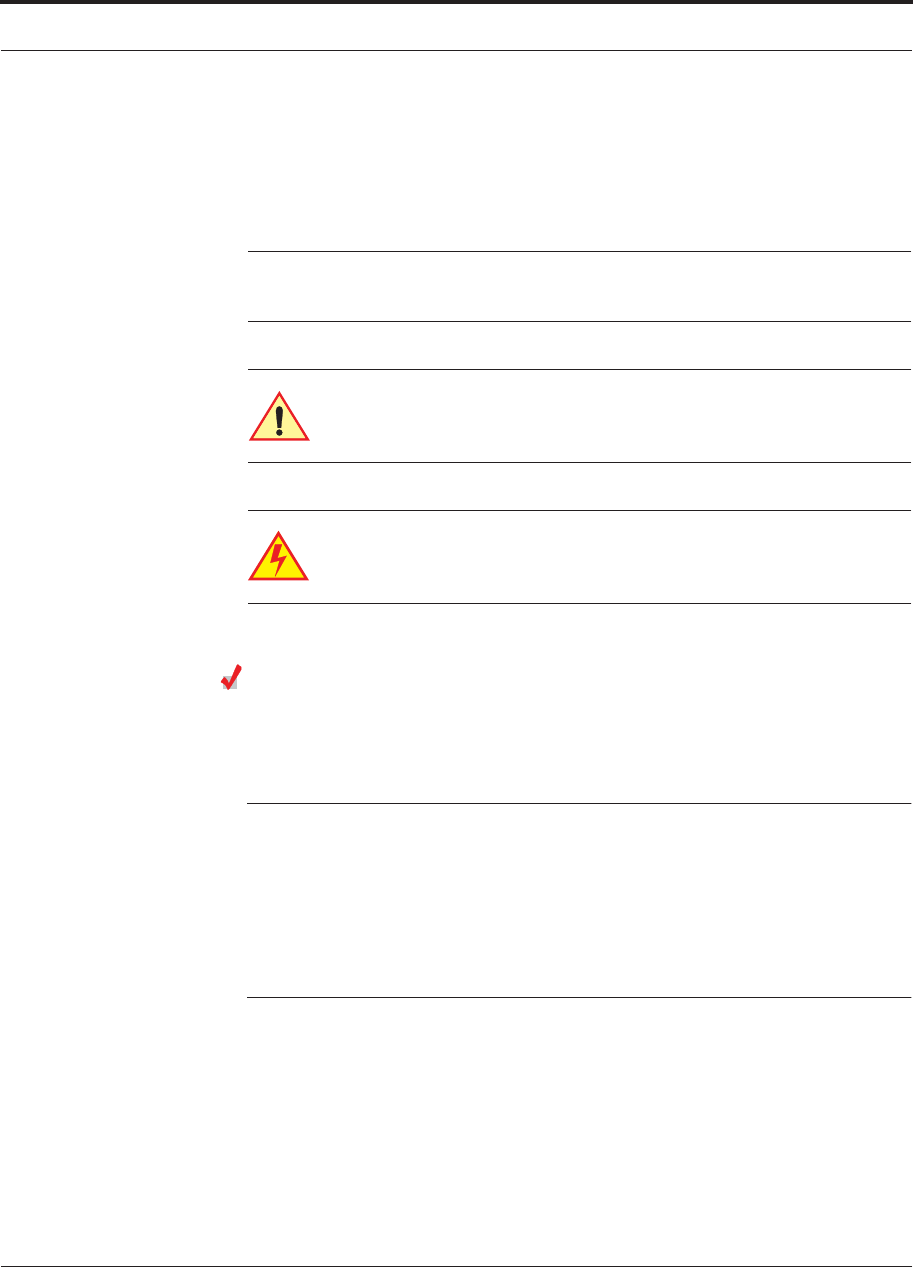
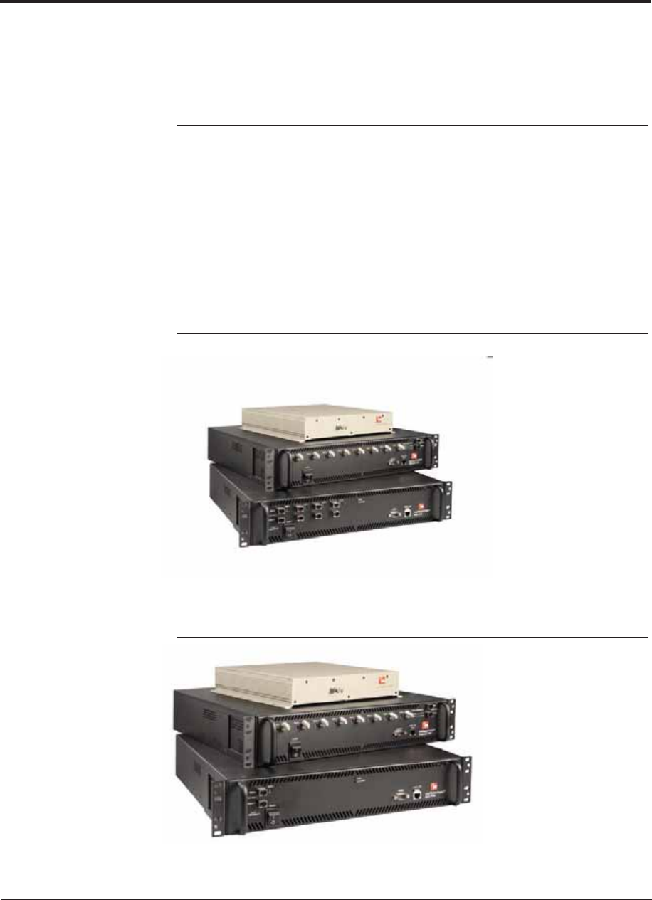
Figure 2-1 Fusion Wideband System Hardware
Figure 2-2 Fusion Wideband One Port System Hardware
Help Hot Line (U.S. only): 1-800-530-9960 2-5
D-620616-0-20 Rev G CONFIDENTIAL
System OA&M Capabilities Overview
2.3 System OA&M Capabilities Overview
InterReach Fusion Wideband is microprocessor controlled and contains firmware to
enable much of the operations, administration, and maintenance (OA&M) functionality.
Complete alarming, down to the field replaceable unit (that is, Fusion Wideband
Main Hub, Expansion Hub, and Remote Access Unit) and the cabling infrastructure,
is available. All events occurring in a system, defined as a Fusion Wideband Main
Hub and all of its associated Expansion Hubs and Remote Access Units, are automat-
ically reported to the Main Hub. The Main Hub monitors system status and communi-
cates that status using the following methods:
• Normally closed (NC) alarm contact closures can be tied to standard NC alarm
monitoring systems or directly to a base station for basic alarm monitoring.
• Connection Methods:
• The Main Hub’s front panel RJ-45 port connects directly to a PC (for local
Ethernet access).
• The Main Hub’s front panel RS-232 serial port connects directly to a modem
(for remote access).
• Remote access is also available with an optional 100BASE-T LAN switch con-
nections to the RJ-45 port.
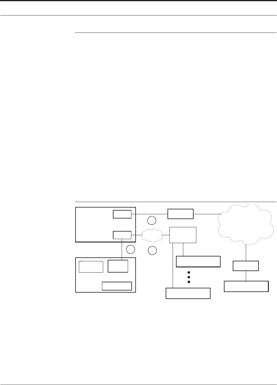
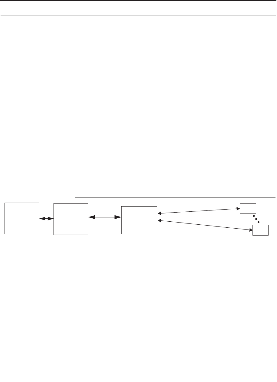
Figure 2-3 Three Methods for OA&M Communications
PSTN
RS-232
RS-232 Ethernet
PC/Laptop
running a
Modem
Fusion Wideband Main Hub
Modem
Fusion Wideband Main Hub
Ethernet
LAN
Switch
F-conn.
Fusion Wideband Main Hub
Fusion Wideband Main Hub
Standard Browser
Use AdminBrowser to configure
or monitor a local or a remote
Fusion Wideband system.
TCP/IP
1
2
3
RJ-45
Ethernet
Admin Browser
RS-232
Modem
AdminBrowser OA&M software runs on the Fusion Wideband Main Hub micropro-
cessor and communicates to its downstream Expansion Hubs and associated RAUs.
Using AdminBrowser, you can perform the following from any standard web browser
(Internet Explorer) running on your PC/laptop system:
• Configure a newly installed system
• Change system parameters
System OA&M Capabilities Overview
2-6 InterReach Fusion Wideband Installation, Operation, and Reference Manual
CONFIDENTIAL D-620616-0-20 Rev G
• Perform an end-to-end system test
• Query system status
Refer to the AdminBrowser User Manual (D-620607-0-20) for information about
installing and using AdminBrowser software.
2.3.1 System Monitoring and Reporting
Each Fusion Wideband Main Hub in the system constantly monitors itself, its Expan-
sion Hubs, and their downstream RAUs for internal fault and warning conditions. The
results of this monitoring are stored in memory and compared against new results.
When a Main or Expansion Hub detects a change in status, it reports a fault or warn-
ing alarm. Faults are also indicated locally by red status LEDs. Both faults and warn-
ings are reported to AdminBrowser software and displayed on a PC/laptop connected
to the Main Hub’s RJ-45 port. Passive antennas connected to the RAUs are not moni-
tored automatically. Perform a System Test to retrieve status information about anten-
nas.
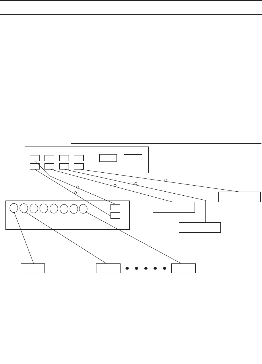
Using AdminBrowser, you can install a new system or new components, change sys-
tem parameters, and query system status. Figure 2-4 illustrates how the system
reports its status to AdminBrowser.
Figure 2-4 System Monitoring and Reporting
Each RAU passes its status to
the Hub.
If a fault is detected, the
ALARM LED is red. If no fault
is detected, the LED is green.
The Expansion Hub queries
the status of each RAU and
compares it to the previously
stored status.
If a fault is detected, LEDs on
the front panel turn red.
Fusion Wideband
Main Hub
AdminBrowser
RAU
RAU
Use a standard
browser to communi-
cate with remotely or
locally installed Fusion
Wideband systems run-
ning AdminBrowser.
If a fault or warning
condition is reported,
the AdminBrowser
graphical user inter-
face indicates the prob-
lem on your standard
PC browser.
web browser
Fusion Wideband
Expansion
Hub
PC/Laptop
running a
standard
The Main Hub queries
status of each Expan-
sion Hub and each
RAU and compares it
to previously stored
status.
If a fault is detected,
LEDs on the front panel
turn red.
AdminBrowser
2.3.2 Using Alarm Contacts
You can connect the DB-9 female connector on the rear panel of the Fusion Wide-
band Main Hub to a local base station or to a daisy-chained series of Fusion and/or
FlexWave Focus systems.
Help Hot Line (U.S. only): 1-800-530-9960 2-7
D-620616-0-20 Rev G CONFIDENTIAL
System Connectivity
When you connect FlexWave Focus or a BTS to the Fusion Wideband, the Fusion
Wideband Main Hub outputs the alarms (alarm source) and FlexWave Focus or the
BTS receives the alarms (alarm sense). This is described in Section 7.7.1 on page
7-59.
2.4 System Connectivity
The double star architecture of the Fusion Wideband system, illustrated in Figure 2-5,
provides excellent system scalability and reliability. The system requires only one
pair of fibers for eight antenna points. This makes any system expansion, such as add-
ing an extra antenna for additional coverage, potentially as easy as pulling an extra
CATV cable.
Figure 2-5 Fusion Wideband’s Double Star Architecture
Main Hub
RS-232
PORT 1 PORT 2 PORT 3 PORT 4
Expansion Hub Expansion Hub
Fiber
Expansion Hub
Expansion Hub
CATVCATV (RG-59, 6, or 11) CATV
up to 8 RAUs per Expansion Hub
RAU RAU RAU
RJ-45
System Operation
2-8 InterReach Fusion Wideband Installation, Operation, and Reference Manual
CONFIDENTIAL D-620616-0-20 Rev G
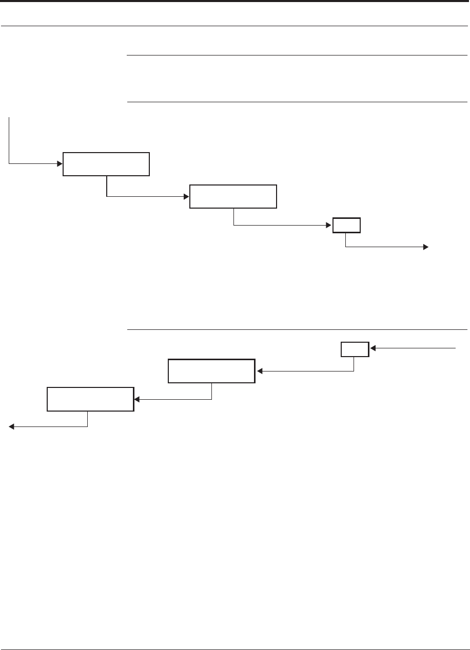
2.5 System Operation
Figure 2-6 Downlink (Base Station to Wireless Devices)
Main Hub
RAU
The Main Hub receives downlink RF signals from
a base station using 50 Ohm coaxial cable.
The Main Hub converts the RF signals to IF, then
to optical signals and sends them to Expansion
Hubs (up to four) using optical fiber cable.
The Expansion Hub converts the optical sig-
nals to electrical signals and sends them to
RAUs (up to eight) using 75 Ohm CATV cable.
The RAU converts the IF signals
to RF and sends them to passive
antennas using 50 Ohm coaxial
cable.
Expansion Hub
Figure 2-7 Uplink (Wireless Devices to Base Station)
Main Hub
RAU
The Main Hub sends
uplink RF signals to a
base station using
50 Ohm coaxial cable.
The Main Hub receives
the optical signals from
the Expansion Hubs (up
to four) using optical
fiber cable and con-
verts them to RF sig-
nals.
The Expansion Hub
receives the IF signals
from the RAUs (up to
eight) using CATV cable
and converts them to
optical signals.
The RAU receives uplink RF
signals from the passive
antenna using 50 Ohm coaxial
cable and converts them to IF
signals.
Expansion Hub

Help Hot Line (U.S. only): 1-800-530-9960 2-9
D-620616-0-20 Rev G CONFIDENTIAL
System Specifications
2.6 System Specifications
Table 2-1 Physical Specifications
Parameter Main Hub Expansion Hub Remote Access
Unit
IF/RF Connectors 4-type N, femalea (50 Ohm),
1 Downlink/Uplink pair per band
8-type F, female (CATV 75 Ohm) One F, female
(CATV -75 Ohm)
One N, femaleb
(antenna - 50 Ohm)
External Alarm Connector
(contact source)
One, 9-pin D-sub, female One, 9-pin D-sub, female —
ADMIN/LAN Interface
Connectors
One RJ-45, female
One 9-pin D-sub, male for
optional modem
One RJ-45, female
One 9-pin D-sub, male
—
Fiber Connectorsc4 pair, SC/APCdOne pair, SC/APC —
LED Alarm and Status
Indicators
Unit Status (One pair):
• Power
• Main Hub Status
Downstream Unit Status
(One per fiber port):
• Expansion Hub/RAU
Unit Status (One pair):
Power and Expansion Hub Status
Fiber Link Status (One pair):
DL Status and UL Status
Port Status:
One per F connector port and
Link/RAU
Unit Status (One
pair):
• Link
• Alarm
Power (AC Option)
Rating: 100–240V AC, 1A,
50–60 Hz
Operating Range: 90–132V
AC/170-250V AC auto-ranging
Rating: 100–240V AC, 6A,
50–60 Hz
Operating Range: 90–132V
AC/170-250V AC auto-ranging
—
Power (DC Option) Rating: 38–64V DC, 2.5A Rating: 38-64V DC, 14A —
Power Consumption (W) 30 4 RAUs: 290 typical, 360 Max.
8 RAUs: 500 typical, 630 Max.
—
Enclosure Dimen-
sionse
(HuWuD) (Excluding
angle- brackets for 19''
rack mounting of hub)
89 mm × 438 mm × 381 mm
(3.5 in. × 17.25 in. × 15 in.) (2U)
89 mm × 438 mm × 381 mm
(3.5 in. × 17.25 in. × 15 in.) (2U)
54 mm x 286 mm x
281 mm
(2.13 in. × 11.25 in.
× 11.13 in.)
Weight < 5.5 kg (< 12 lbs.) < 6.6 kg (< 14.5 lbs.) < 2.1 kg (< 4.6 lbs.)
a. 6-type N, female connectors for FSN-W2-MH-1, FSN-W2-MH-3, and FSN-W4-MH-1 Main Hub.
b. 2-type N, female connectors for FSN-W1-1921-1, FSN-W2-808519-1, FSN-W2-7575-1, FSN-W2-7070-1, FSN-W3-2626-1,
FSN-W4-702121-1-HP, FSN-W4-752121-1-HP, and FSN-2500-2-WMAX RAUs.
c. It is critical to system performance that only SC/APC fiber connectors are used throughout the fiber network, including fiber distribu-
tion panels.
d. FSN-W1-MH-2-1P, FSN-W2-MH-3-1P, FSN-W3-MH-1P, and FSN-W4-MH-1P support only one pair, SP/APC fibers.
e. Excluding angle-brackets for 19” rack mounting of hub.
Note: The Fusion Wideband Main Hub’s typical power consumption assumes that the CATV RG-59 cable length is no more than 130

System Specifications
2-10 InterReach Fusion Wideband Installation, Operation, and Reference Manual
CONFIDENTIAL D-620616-0-20 Rev G
meters, the RG-6 cable length is no more than 140 meters, and RG-11 cable length is no more than 235 meters using CommScope
2065V, 2279V, and 2293K cables.
Table 2-2 Wavelength and Laser Power Specifications
Measured Output Power
Wavelength Main Hub Expansion Hub
1310 nm +20 nm 890 uW 3.8 mW
Table 2-3 Environmental Specifications
Parameter Main Hub and Expansion Hub RAU
Operating Temperature 0° to +45°C (+32° to +113°F) –25° to +45°C (–13°
to +113°F)
Non-operating Tempera-
ture
–20° to +85°C (–4° to +185°F) –25° to +85°C (–13°
to +185°F)
Operating Humidity;
non-condensing
5% to 95% 5% to 95%
Table 2-4 Frequency Bands Covered by Fusion Wideband RAUs
Fusion Wideband RAU Part Number
Fusion
Wide-
band
Band
RF Passband
Downlink
(MHz) Uplink
(MHz)
MAIN
HUB/
RAU
Band
RAU
Band-
width
2100/1800 FSN-W1-2118-1 2100 2110-2170 1920-1980 1 60 MHz
1800 1805-1880 1710-1785 2 75 MHz
2100 High Power (single-band
RAU)
FSN-W1-21HP-1 2100 2110-2170 1920-1980 1 60 MHz
1900/AWS FSN-W1-1921-1 1900
(A-F)
1930-1990 1850-1910 1 60 MHz
AWS 2110-2155 1710-1755 2 45 MHz
800/850/1900 FSN-W2-808519-1 800 851-869 806-824 1
(sub-band
1A)
18 MHz
850 869-894 824-849 3
(sub-band
1B)
25 MHz
1900
(A-F)
1930-1990 1850-1910 2 60 MHz

Help Hot Line (U.S. only): 1-800-530-9960 2-11
D-620616-0-20 Rev G CONFIDENTIAL
System Specifications
700/AWS FSN-W2-7021-1 700
(Upper C)
746-757 776-787 1
(sub-band
1A)
11 MHz
700
(Lower
ABC)
728-746 698-716 3
(sub-band
1B)
18 MHz
AWS 2110-2155 1710-1755 2 45 MHz
700/700 MIMO (Upper C) FSN-W2-7575-1 700
(Upper C)
746-757 776-787 1 (sub-
band 1A)
11 MHz
700
(Upper C)
746-757 776-787 3 (sub-
band 1B)
11 MHz
700/700 MIMO (Lower ABC) FSN-W2-7070-1 700
(Lower
ABC)
728-746 698-716 1 (sub-
band 1A)
18 MHz
700
(Lower
ABC)
728-746 698-716 3 (sub-
band 1B)
18 MHz
700 ABC/AWS HP/AWS HP FSN-W4-702121-1-HP AWS 2110-2155 1710-1755 1
(sub-band
1A)
45 MHz
700
(Lower
ABC)
728-746 698-716 3
(sub-band
1B)
18 MHz
AWS 2110-2155 1710-1755 2 45 MHz
700 UC/AWS HP/AWS HP FSN-W4-752121-1-HP AWS 2110-2155 1710-1755 1
(sub-band
1A)
45 MHz
700
(Upper C)
746-757 776-787 3
(sub-band
1B)
11 MHz
AWS 2110-2155 1710-1755 2 45 MHz
2500/2500 FSN-2500-2-WMAX 2500 2496-2690 2496-2690 1 30 MHz
2500 2496-2690 2496-2690 2 30 MHz
2600/2600 FSN-W3-2626-1 2600 2620-2690 2500-2570 1 70 MHz
2600 2620-2690 2500-2570 2 70 MHz
Table 2-4 Frequency Bands Covered by Fusion Wideband RAUs (continued)
Fusion Wideband RAU Part Number
Fusion
Wide-
band
Band
RF Passband
Downlink
(MHz) Uplink
(MHz)
MAIN
HUB/
RAU
Band
RAU
Band-
width

System Specifications
2-12 InterReach Fusion Wideband Installation, Operation, and Reference Manual
CONFIDENTIAL D-620616-0-20 Rev G
2.6.1 RF End-to-End Performance
The following tables list the RF end-to-end performance of each protocol.
NOTE: The system gain is adjustable in 1 dB steps from 0 to 15 dB, and the
gain of each RAU can be attenuated 0 or 10 dB.
2100/1800 RAU
Table 2-5 2100 MHz RF End-to-End Performance
Typical
Parameter Downlink Uplink
Average gain with 130 m RG-59 at 25°C (77°F) (dB)
15 15
Ripple with 130 m RG-59 (dB)
55
Output IP3 (dBm)
38
Input IP3 (dBm)
-5
Output 1 dB Compression Point (dBm)
26
Noise Figure 1 MH, 1 EH, 8 RAUs (dB)
17
Noise Figure 1 MH, 4 EH, 32 RAUs (dB)
23
Table 2-6 1800 MHz RF End-to-End Performance
Typical
Parameter Downlink Uplink
Average gain with 130 m RG-59 at 25°C (77°F) (dB)
15 15
Ripple with 130 m RG-59 (dB)
4.5 5
Output IP3 (dBm)
38
Input IP3 (dBm)
–5
Output 1 dB Compression Point (dBm)
26
Noise Figure 1 MH, 1 EH, 8 RAUs (dB)
17
Noise Figure 1 MH, 4 EH, 32 RAUs (dB)
23

Help Hot Line (U.S. only): 1-800-530-9960 2-13
D-620616-0-20 Rev G CONFIDENTIAL
System Specifications
2100 High Power RAU
Table 2-7 2100 MHz High Power RF End-to-End Performance
Typical
Parameter Downlink Uplink
Average gain with 130 m RG-59 at 25°C (77°F) (dB) *
* The system Downlink gain is adjustable in 1 dB steps from 7 to 22 dB (the High Power RAU adds 7
dB of Downlink gain).
†
† The system Uplink gain is adjustable in 1 dB steps from 0 to 15 dB.
22 15
Ripple with 130 m RG-59 (dB)
4.5 5
Output IP3 (dBm)
44
Input IP3 (dBm)
–5
Output 1 dB Compression Point (dBm)
33
Noise Figure 1 MH, 1 EH, 8 RAUs (dB)
17
Noise Figure 1 MH, 4 EH, 32 RAUs (dB)
23
1900/AWS RAU
Table 2-8 1900 MHz RF End-to-End Performance
Typical
Parameter Downlink Uplink
Average gain with 130 m RG-59 at 25°C (77°F) (dB)
15 15
Ripple with 130 m RG-59 (dB)
3.5 4
Output IP3 (dBm)
38
Input IP3 (dBm)
–5
Output 1 dB Compression Point (dBm)
26
Noise Figure 1 MH, 1 EH, 8 RAUs (dB)
17
Noise Figure 1 MH, 4 EH, 32 RAUs (dB)
23
Table 2-9 AWS RF End-to-End Performance
Typical
Parameter Downlink Uplink
Average gain with 130 m RG-59 at 25°C (77°F) (dB)
15 15
Ripple with 130 m RG-59 (dB)
3.5 4
Output IP3 (dBm)
38
Input IP3 (dBm)
–5
Output 1 dB Compression Point (dBm)
26

System Specifications
2-14 InterReach Fusion Wideband Installation, Operation, and Reference Manual
CONFIDENTIAL D-620616-0-20 Rev G
800/850/1900 RAU
Table 2-10 800 MHz RF End-to-End Performance
Typical
Parameter Downlink Uplink
Average gain with 130 m RG-59 at 25°C (77°F) (dB)
15 15
Ripple with 130 m RG-59 (dB)
2.5 3
Output IP3 (dBm)
37
Input IP3 (dBm)
–5
Output 1 dB Compression Point (dBm)
25
Noise Figure 1 MH, 1 EH, 8 RAUs (dB)
17
Noise Figure 1 MH, 4 EH, 32 RAUs (dB)
23
Table 2-11 850 MHz RF End-to-End Performance
Typical
Parameter Downlink Uplink
Average gain with 130 m RG-59 at 25°C (77°F) (dB)
15 15
Ripple with 130 m RG-59 (dB)
2.5 3
Output IP3 (dBm)
37
Input IP3 (dBm)
–5
Output 1 dB Compression Point (dBm)
25
Noise Figure 1 MH, 1 EH, 8 RAUs (dB)
17
Noise Figure 1 MH, 4 EH, 32 RAUs (dB)
23
Noise Figure 1 MH, 1 EH, 8 RAUs (dB)
17
Noise Figure 1 MH, 4 EH, 32 RAUs (dB)
23
Table 2-9 AWS RF End-to-End Performance
Typical
Parameter Downlink Uplink

Table 2-12 1900 MHz RF End-to-End Performance
Typical
Parameter Downlink Uplink
Average gain with 130 m RG-59 at 25°C (77°F) (dB)
15 15
Ripple with 130 m RG-59 (dB)
3.5 4
Output IP3 (dBm)
38
Input IP3 (dBm)
–5
Output 1 dB Compression Point (dBm)
26
Noise Figure 1 MH, 1 EH, 8 RAUs (dB)
17
Noise Figure 1 MH, 4 EH, 32 RAUs (dB)
23
Help Hot Line (U.S. only): 1-800-530-9960 2-15
D-620616-0-20 Rev G CONFIDENTIAL
System Specifications
700/AWS RAU
Table 2-13 700 MHz (Lower ABC) RF End-to-End Performance
Typical
Parameter Downlink Uplink
Average gain with 130 m RG-59 at 25°C (77°F) (dB)
15 15
Ripple with 130 m RG-59 (dB)
2.5 3
Output IP3 (dBm)
34
Input IP3 (dBm)
–5
Output 1 dB Compression Point (dBm)
22
Noise Figure 1 MH, 1 EH, 8 RAUs (dB)
20
Noise Figure 1 MH, 4 EH, 32 RAUs (dB)
26
Table 2-14 700 MHz (Upper C) RF End-to-End Performance
Typical
Parameter Downlink Uplink
Average gain with 130 m RG-59 at 25°C (77°F) (dB)
15 15
Ripple with 130 m RG-59 (dB)
2.5 3
Output IP3 (dBm)
34
Input IP3 (dBm)
–5
Output 1 dB Compression Point (dBm)
22
Noise Figure 1 MH, 1 EH, 8 RAUs (dB)
20
Noise Figure 1 MH, 4 EH, 32 RAUs (dB)
26

Table 2-15 AWS RF End-to-End Performance
Typical
Parameter Downlink Uplink
Average gain with 130 m RG-59 at 25°C (77°F) (dB)
15 15
Ripple with 130 m RG-59 (dB)
3.5 4
Output IP3 (dBm)
38
Input IP3 (dBm)
–5
Output 1 dB Compression Point (dBm)
26
Noise Figure 1 MH, 1 EH, 8 RAUs (dB)
17
Noise Figure 1 MH, 4 EH, 32 RAUs (dB)
23
System Specifications
2-16 InterReach Fusion Wideband Installation, Operation, and Reference Manual
CONFIDENTIAL D-620616-0-20 Rev G
700/700 (Upper C) MIMO RAU
Table 2-16 700 MHz (Upper C) RF End-to-End Performance
Typical
Parameter Downlink Uplink
Average gain with 130 m RG-59 at 25°C (77°F) (dB)
15 15
Ripple with 130 m RG-59 (dB)
2.5 3
Output IP3 (dBm)
38
Input IP3 (dBm)
–5
Output 1 dB Compression Point (dBm)
26
Noise Figure 1 MH, 1 EH, 8 RAUs (dB)
17
Noise Figure 1 MH, 4 EH, 32 RAUs (dB)
23
700/700 (Lower ABC) MIMO RAU
Table 2-17 700 MHz (Lower ABC) RF End-to-End Performance
Typical
Parameter Downlink Uplink
Average gain with 130 m RG-59 at 25°C (77°F) (dB)
15 15
Ripple with 130 m RG-59 (dB)
2.5 3
Output IP3 (dBm)
38
Input IP3 (dBm)
–5
Output 1 dB Compression Point (dBm)
26
Noise Figure 1 MH, 1 EH, 8 RAUs (dB)
17
Noise Figure 1 MH, 4 EH, 32 RAUs (dB)
23

Help Hot Line (U.S. only): 1-800-530-9960 2-17
D-620616-0-20 Rev G CONFIDENTIAL
System Specifications
700 ABC/AWS HP/AWS HP RAU
Table 2-18 700 MHz (Lower ABC) RF End-to-End Performance
Typical
Parameter Downlink Uplink
Average gain with 130 m RG-59 at 25°C (77°F) (dB)
15 15
Ripple with 130 m RG-59 (dB)
2.5 3
Output IP3 (dBm)
38
Input IP3 (dBm)
–5
Output 1 dB Compression Point (dBm)
26
Noise Figure 1 MH, 1 EH, 8 RAUs (dB)
16
Noise Figure 1 MH, 4 EH, 32 RAUs (dB)
22
Table 2-19 AWS RF End-to-End Performance
Typical
Parameter Downlink Uplink
Average gain with 130 m RG-59 at 25°C (77°F) (dB)
20 15
Ripple with 130 m RG-59 (dB)
3.5 4
Output IP3 (dBm)
43
Input IP3 (dBm)
–5
Output 1 dB Compression Point (dBm)
31
Noise Figure 1 MH, 1 EH, 8 RAUs (dB)
17
Noise Figure 1 MH, 4 EH, 32 RAUs (dB)
23
700 UC/AWS HP/AWS HP RAU
Table 2-20 700 MHz (Upper C) RF End-to-End Performance
Typical
Parameter Downlink Uplink
Average gain with 130 m RG-59 at 25°C (77°F) (dB)
15 15
Ripple with 130 m RG-59 (dB)
2.5 3
Output IP3 (dBm)
38
Input IP3 (dBm)
–5
Output 1 dB Compression Point (dBm)
26
Noise Figure 1 MH, 1 EH, 8 RAUs (dB)
16
Noise Figure 1 MH, 4 EH, 32 RAUs (dB)
22

Table 2-21 AWS RF End-to-End Performance
Typical
Parameter Downlink Uplink
Average gain with 130 m RG-59 at 25°C (77°F) (dB)
20 15
Ripple with 130 m RG-59 (dB)
3.5 4
Output IP3 (dBm)
43
Input IP3 (dBm)
–5
Output 1 dB Compression Point (dBm)
31
Noise Figure 1 MH, 1 EH, 8 RAUs (dB)
17
Noise Figure 1 MH, 4 EH, 32 RAUs (dB)
23
System Specifications
2-18 InterReach Fusion Wideband Installation, Operation, and Reference Manual
CONFIDENTIAL D-620616-0-20 Rev G

Help Hot Line (U.S. only): 1-800-530-9960 2-19
D-620616-0-20 Rev G CONFIDENTIAL
System Specifications
2500/2500 RAU
Table 2-22
Typical
Parameter Downlink Uplink
Average gain with 130 m RG-59 at 25°C (77°F) (dB)
15 15
Ripple with 130 m RG-59 (dB)
4.5 4.5
Output IP3 (dBm)
42.5
Input IP3 (dBm)
–5
Output 1 dB Compression Point (dBm)
32
Noise Figure 1 MH, 1 EH, 8 RAUs (dB)
17
Noise Figure 1 MH, 4 EH, 32 RAUs (dB)
23
2500 MHz RF End-to-End Performance
2600/2600 RAU
Table 2-23
Typical
Parameter Downlink Uplink
Average gain with 130 m RG-59 at 25°C (77°F) (dB)
15 15
Ripple with 130 m RG-59 (dB)
4.5 5
Output IP3 (dBm)
38
Input IP3 (dBm)
–5
Output 1 dB Compression Point (dBm)
26
Noise Figure 1 MH, 1 EH, 8 RAUs (dB)
17
Noise Figure 1 MH, 4 EH, 32 RAUs (dB)
23
2600 MHz RF End-to-End Performance

System Specifications
2-20 InterReach Fusion Wideband Installation, Operation, and Reference Manual
CONFIDENTIAL D-620616-0-20 Rev G

InterReach Fusion Wideband Installation, Operation, and Reference Manual 3-1
D-620616-0-20 Rev G CONFIDENTIAL
SECTION 3 Fusion Wideband Main Hub
This section contains the following subsections:
• Section 3.1 Fusion Wideband Main Hub Overview . . . . . . . . . . . . . . . . . . . . 3-1
• Section 3.2 Fusion Wideband Main Hub Front Panel . . . . . . . . . . . . . . . . . . . 3-4
• Section 3.3 Fusion Wideband Main Hub Rear Panel . . . . . . . . . . . . . . . . . . . 3-8
• Section 3.4 Main Hub Specifications . . . . . . . . . . . . . . . . . . . . . . . . . . . . . . 3-10
• Section 3.5 Faults, Warnings, and Status Messages . . . . . . . . . . . . . . . . . . . 3-11
3.1 Fusion Wideband Main Hub Overview
The Fusion Wideband Main Hub (shown in Figure 3-1) distributes up to three indi-
vidual (Band 1, 2, and 3) downlink RF signals from a base station, repeater, or Flex-
Wave Focus system to up to four Expansion Hubs, which in turn distribute the signals
to up to 32 Remote Access Units. The Main Hub also combines uplink signals from
the associated Expansion Hubs.
Fusion Wideband is a multi-band system. One RF source (Band 1 or RF1) goes to the
60 MHz band and the other RF source (Band 2 or RF2) goes to the 75 MHz band.
Band 3 (or RF3) goes to a 25 MHz sub-band of the 60 MHz band and is functional
only with the 800/850/1900, 700/AWS, 700/700 (Upper C) MIMO, 700/700 (Lower
ABC) MIMO, 700 ABC/AWS HP/AWS HP, and 700 UC/AWS HP/AWS HP RAU.
The system installs in a 19" equipment rack and is usually co-located with the RF
source in a telecommunications closet.
Fusion Wideband Main Hub Overview
3-2 InterReach Fusion Wideband Installation, Operation, and Reference Manual
CONFIDENTIAL D-620616-0-20 Rev G
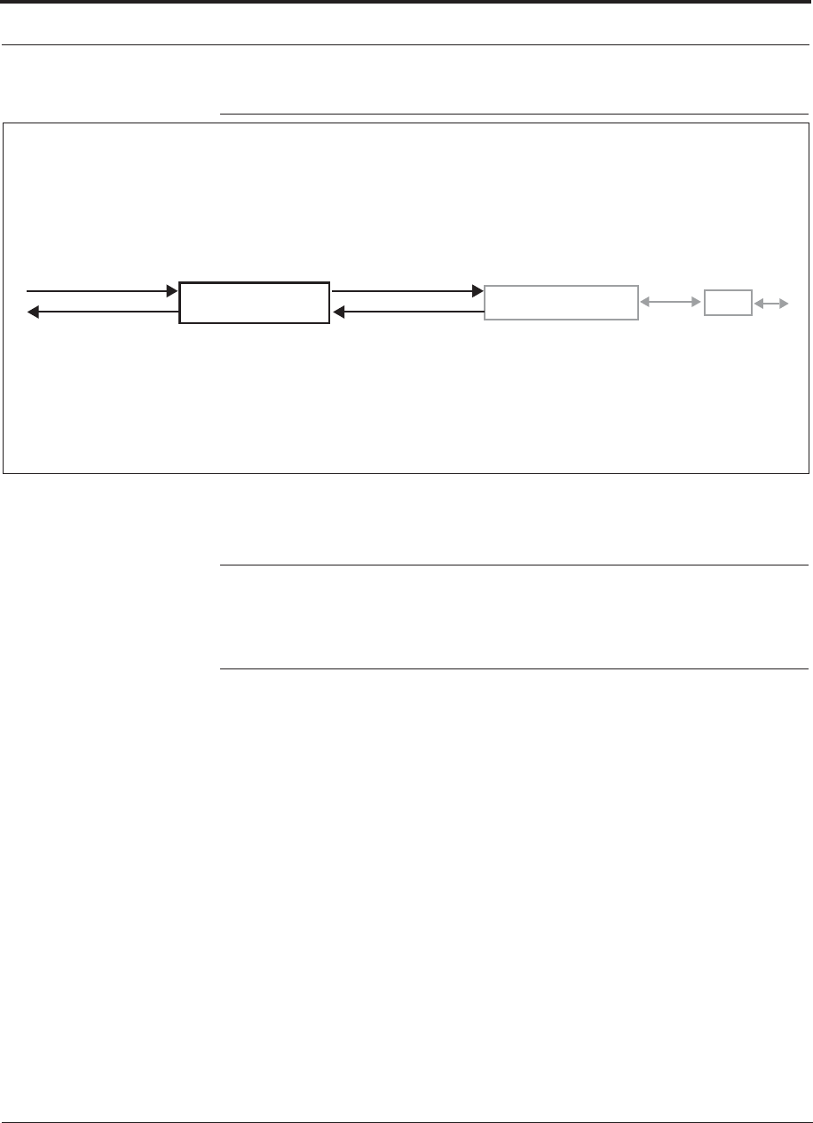
Figure 3-1 Main Hub in a Fusion Wideband System
Fusion Wideband Main Hub Fusion Wideband Expansion Hub RAU
Downlink Path: The Main Hub receives up to 3 individual (Band1, 2, and 3) downlink RF signals from a base station,
repeater, or FlexWave Focus system using 50 Ohm coaxial cable. It converts the signals to IF then to optical and sends them
to up to four Expansion Hubs using fiber optic cable.
The Main Hub also sends OA&M communication to the Expansion Hubs using the fiber optic cable. The Expansion Hubs, in
turn, communicate the OA&M information to the RAUs using CATV cable.
Uplink Path: The Main Hub receives uplink optical signals from up to four Expansion Hubs using fiber optic cables. It con-
verts the signals to IF then to RF and sends them to the respective Band1, 2, and 3 base station, repeater, or FlexWave
Focus system using 50 Ohm coaxial cable.
The Main Hub also receives status information from the Expansion Hubs and all RAUs using the fiber optic cable.
Downlink to Main Hub
Uplink from Main Hub
Downlink from Main Hub
Uplink to Main Hub
RF1, 2, and 3
RF1, 2, and 3
Figure 3-2 shows a detailed view of the major RF and optical functional blocks of the
Main Hub.
NOTE: The Fusion Wideband One Port Main Hub (PNs:
FSN-W1-MH-2-1P, FSN-W2-MH-3-1P, FSN-W3-MH-1P, and
FSN-W4-MH-1P) configuration is a cost reduced version of the Fusion
Wideband Main Hub and supports only one Expansion Hub (up to 8 RAUs).
Help Hot Line (U.S. only): 1-800-530-9960 3-3
D-620616-0-20 Rev G CONFIDENTIAL
Fusion Wideband Main Hub Overview
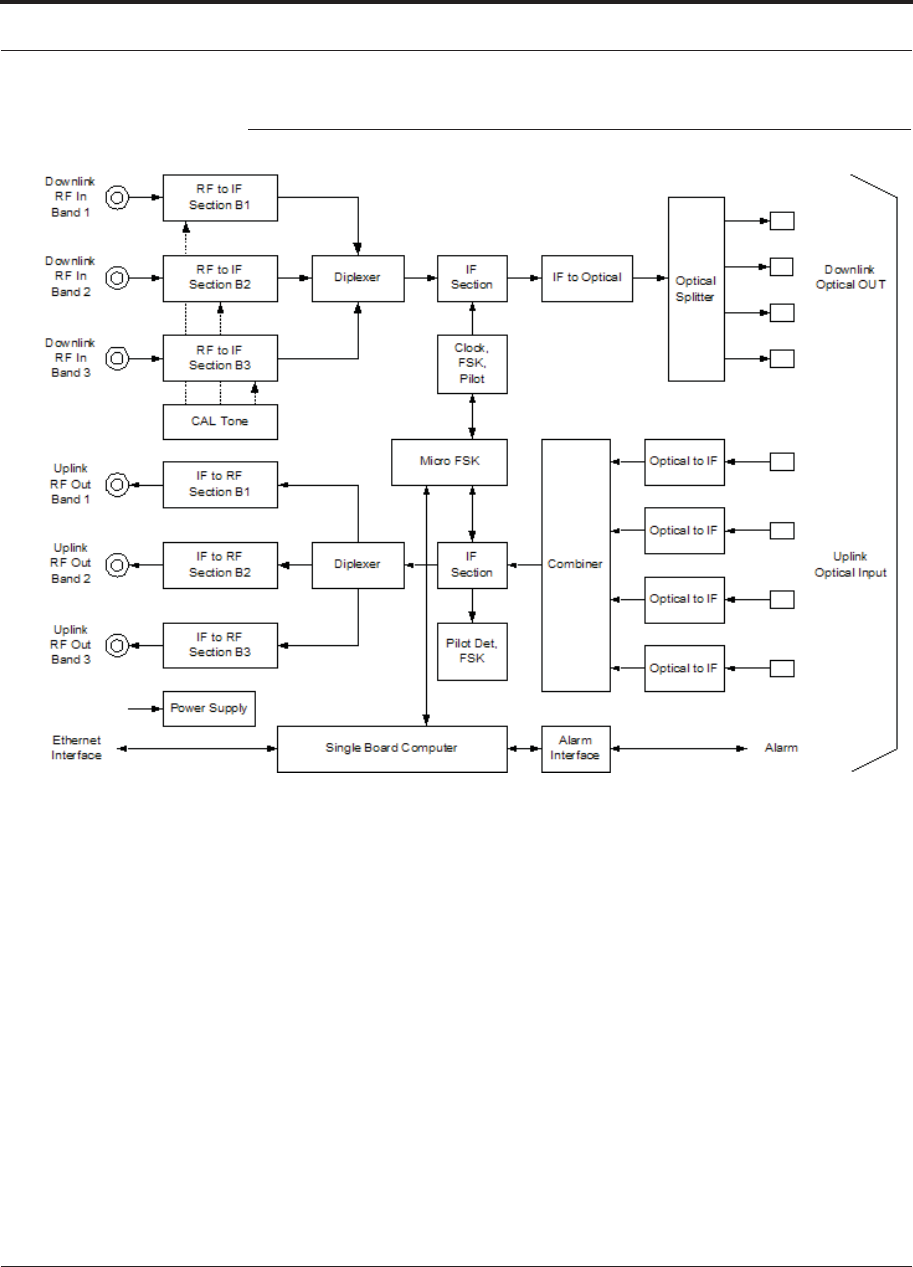
Figure 3-2 Main Hub Block Diagram
CAL Tone
Fusion Wideband Main Hub Front Panel
3-4 InterReach Fusion Wideband Installation, Operation, and Reference Manual
CONFIDENTIAL D-620616-0-20 Rev G
3.2 Fusion Wideband Main Hub Front Panel
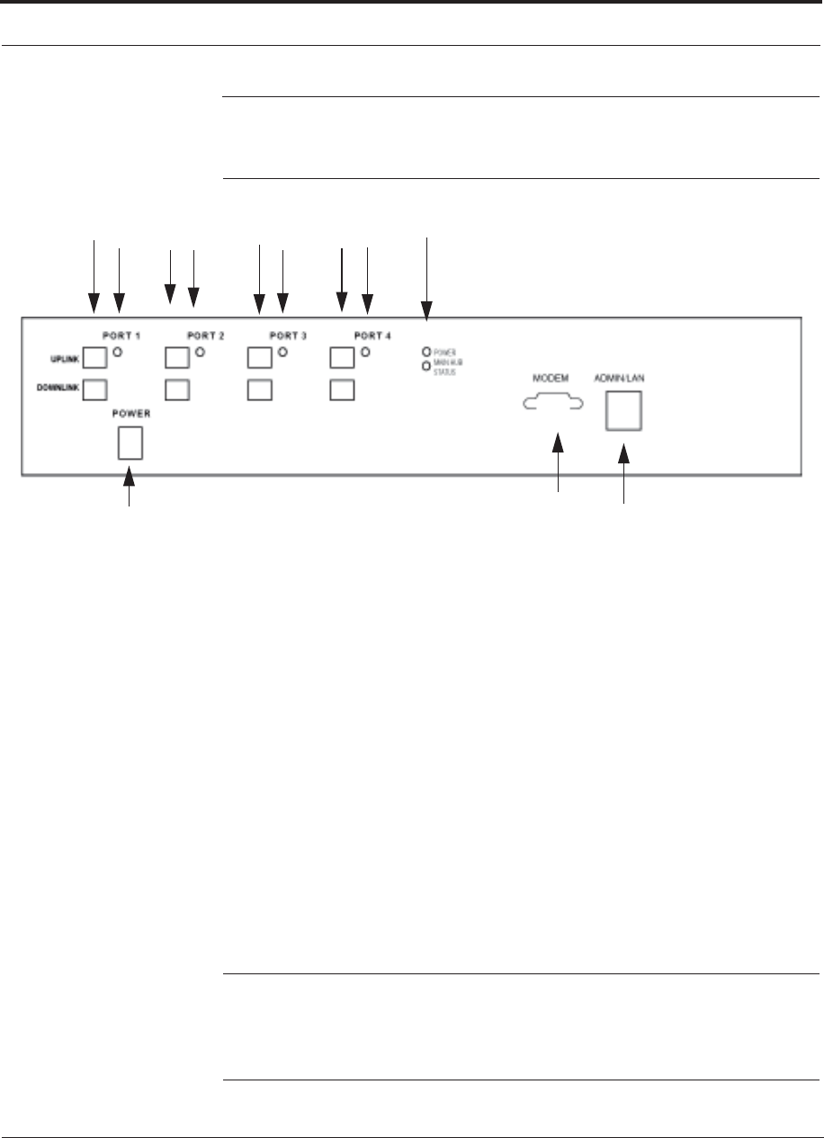
Figure 3-3 Fusion Wideband Main Hub Front Panel
123
6
45
121212
InterReach
Wideband Fusion
Main Hub
1. Four fiber optic ports (labeled PORT 1, PORT 2, PORT 3, PORT 4)
• One standard female SC/APC connector per port for MMF/SMF input (labeled
UPLINK)
• One standard female SC/APC connector per port for MMF/SMF output
(labeled DOWNLINK)
2. Four sets of fiber port LEDs (one set per port)
• One LED per port for port link status and downstream unit status
3. One set of unit status LEDs
• One LED for unit power status (labeled POWER)
• One LED for unit status (labeled MAIN HUB STATUS)
4. One 9-pin D-sub male connector for system remote dial-up communication and
diagnostics using a modem (labeled MODEM)
5. One RJ-45 female connector for system communication and diagnostics using a
PC/laptop with direct connect or using a LAN switch (labeled ADMIN/LAN)
6. Power switch
NOTE: The Fusion Wideband One Port Main Hub (PNs:
FSN-W1-MH-2-1P, FSN-W2-MH-3-1P, FSN-W3-MH-1P, and
FSN-W4-MH-1P) configuration is a cost reduced version of the Fusion
Wideband Main Hub and supports only one Expansion Hub (up to 8 RAUs).

Help Hot Line (U.S. only): 1-800-530-9960 3-5
D-620616-0-20 Rev G CONFIDENTIAL
Fusion Wideband Main Hub Front Panel
3.2.1 Optical Fiber Uplink/Downlink Ports
The optical fiber uplink/downlink ports transmit and receive optical signals between
the Main Hub and up to four Expansion Hubs using industry-standard SMF or MMF
cable. There are four fiber ports on the front panel of the Main Hub; one port per
Expansion Hub. Each fiber port has two female SC/APC connectors:
• Optical Fiber Uplink Connector
This connector (labeled UPLINK) is used to receive the uplink optical signals from
an Expansion Hub.
• Optical Fiber Downlink Connector
This connector (labeled DOWNLINK) is used to transmit the downlink optical sig-
nals to an Expansion Hub.
CAUTION: To avoid damaging the Main Hub’s fiber connector ports,
use only SC/APC fiber cable connectors when using either single-mode
or multi-mode fiber. Additionally, it is critical to system performance
that only SC/APC fiber connectors are used throughout the fiber network, includ-
ing fiber distribution panels.
3.2.2 Communications RS-232 Serial Connector
Remote Monitoring
Use a standard serial cable to connect a modem to the 9-pin D-sub male serial con-
nector for remote monitoring or configuring. The cable typically has a DB-9 female
and a DB-9 female connector. Refer to Appendix A.6 on page A-9 for the cable pin-
out diagram.
Remote monitoring is also available by connecting the RJ-45 (ADMIN/LAN) port to
a LAN switch for remote Ethernet LAN access or direct dial-up router access.
Local Monitoring
Use a crossover Ethernet cable (PN-4069-ADB) to connect a laptop or PC to the
RJ-45 female connector for local monitoring or configuring using the AdminBrowser
resident software. The cable typically has a RJ-45 male connector on both ends. Refer
to Appendix A.5 on page A-8 for the cable pinout.
3.2.3 Main Hub LED Indicators
The unit’s front panel LEDs indicate faults and commanded or fault lockouts. The
LEDs do not indicate warnings or whether the system test has been performed. Use the
LEDs to provide basic information only, or as a backup when you are not using Admin-
Browser.

Fusion Wideband Main Hub Front Panel
3-6 InterReach Fusion Wideband Installation, Operation, and Reference Manual
CONFIDENTIAL D-620616-0-20 Rev G
Upon power up, the Main Hub goes through a 20-second test to check the LED
lamps. During this time, the LEDs blink through the states shown in Table 3-1, letting
you visually verify that the LED lamps and the firmware are functioning properly.
Upon completion of initialization, the LEDs stay in one of the first two states shown
in Table 3-1.
The Main Hub automatically sends the program bands command to all connected
RAUs. A mismatched band causes a fault message to be displayed in AdminBrowser
and places the RAU in a disabled condition.
NOTE: Refer to Section 9.3.2 for troubleshooting using the LEDs.
NOTE: AdminBrowser should be used for troubleshooting the system.
Only use LEDs for backup or confirmation. However, if there are communi-
cation problems within the system, the LEDs may provide additional infor-
mation that is not available using AdminBrowser.
Unit Status LEDs
The Main Hub has one pair of status LEDs, labeled POWER and STATUS, which can
be in one of the states shown in Table 3-1. These LEDs can be:
steady green
steady red
off - no color (valid only during 90 second power cycle)
flashing red (60 ppm)
There is no off state when the unit’s power is on.
Table 3-1 Fusion Wideband Hub Status LED States
LED State Indicates
POWER
STATUS Green
Green
• The Main Hub is connected to power and all power supplies are operating.
• The Main Hub is not reporting a fault; however, the system test may need to
be performed or a warning condition may exist. Use AdminBrowser to deter-
mine this.
POWER
STATUS Green
Red
• The Main Hub is connected to power and all power supplies are operating.
Use AdminBrowser to power status.
• The Main Hub is reporting a fault.
POWER
STATUS Green
Green
(60-ppm)
• The Main Hub is connected to power and all power supplies are operating.
Use Admin Browser to determine power status.
• The Main Hub is reporting a lockout condition.
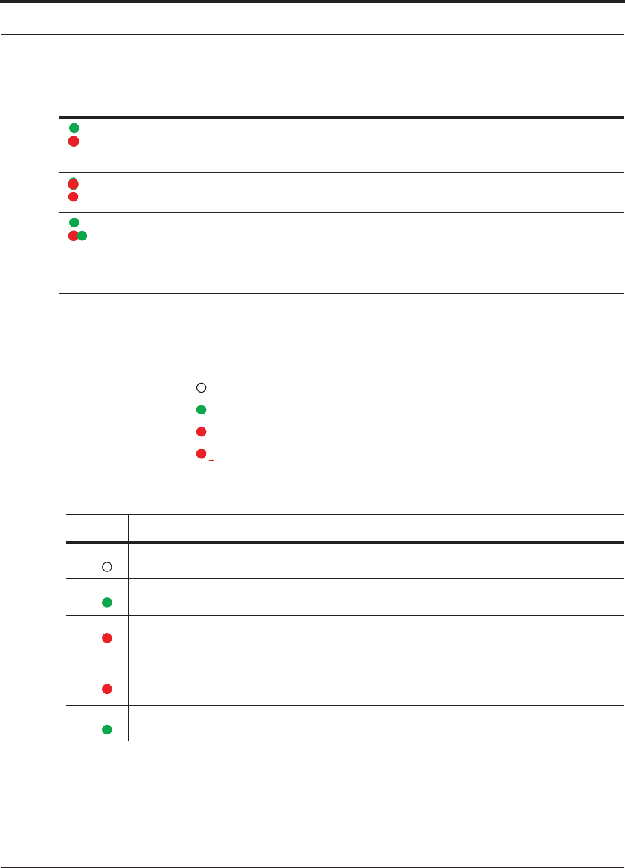
POWER
STATUS
Help Hot Line (U.S. only): 1-800-530-9960 3-7
D-620616-0-20 Rev G CONFIDENTIAL
Fusion Wideband Main Hub Front Panel
Fiber Port LEDs
The Main Hub has one fiber port LED for each of the four fiber ports. The LED can
be in one of the states shown in Table 3-2. This LED can be:
off
steady green
steady red
flashing red (60 ppm)
Green
Red
(60-ppm)
• The Main Hub is connected to power and all power supplies are operating.
• The Main Hub DL input signal level is too high.
POWER
STATUS Red
Red
• One or more power supplies are out-of-specification.
POWER
STATUS Green
Red/Green
(alternating)
• After the System CPU is rebooted, the MH status LED blinks red/green
while the system tree data is built, power up system test is executed, and all
units have their current status updated.
• Should the MH status LED blink red/green after initial power up, either the
System CPU has rebooted or a component of the software has reset.
Table 3-2 Fusion Wideband Hub Port LED States
LED State Indicates
Off • The Expansion Hub is not connected.
Green
• The Expansion Hub is connected.
• There are no faults from the Expansion Hub or any connected RAU.
Red
(60 PPM)
• There was a loss of communications with the Expansion Hub.
Red
(Steady)
• The Expansion Hub is disconnected.
• The Expansion Hub or any connected RAU reported a fault.
Green
(60-ppm)
• The Expansion Hub or any connected RAU reported a lockout condition.
Table 3-1 Fusion Wideband Hub Status LED States (continued)
LED State Indicates
PORT
PORT
PORT
PORT
PORT
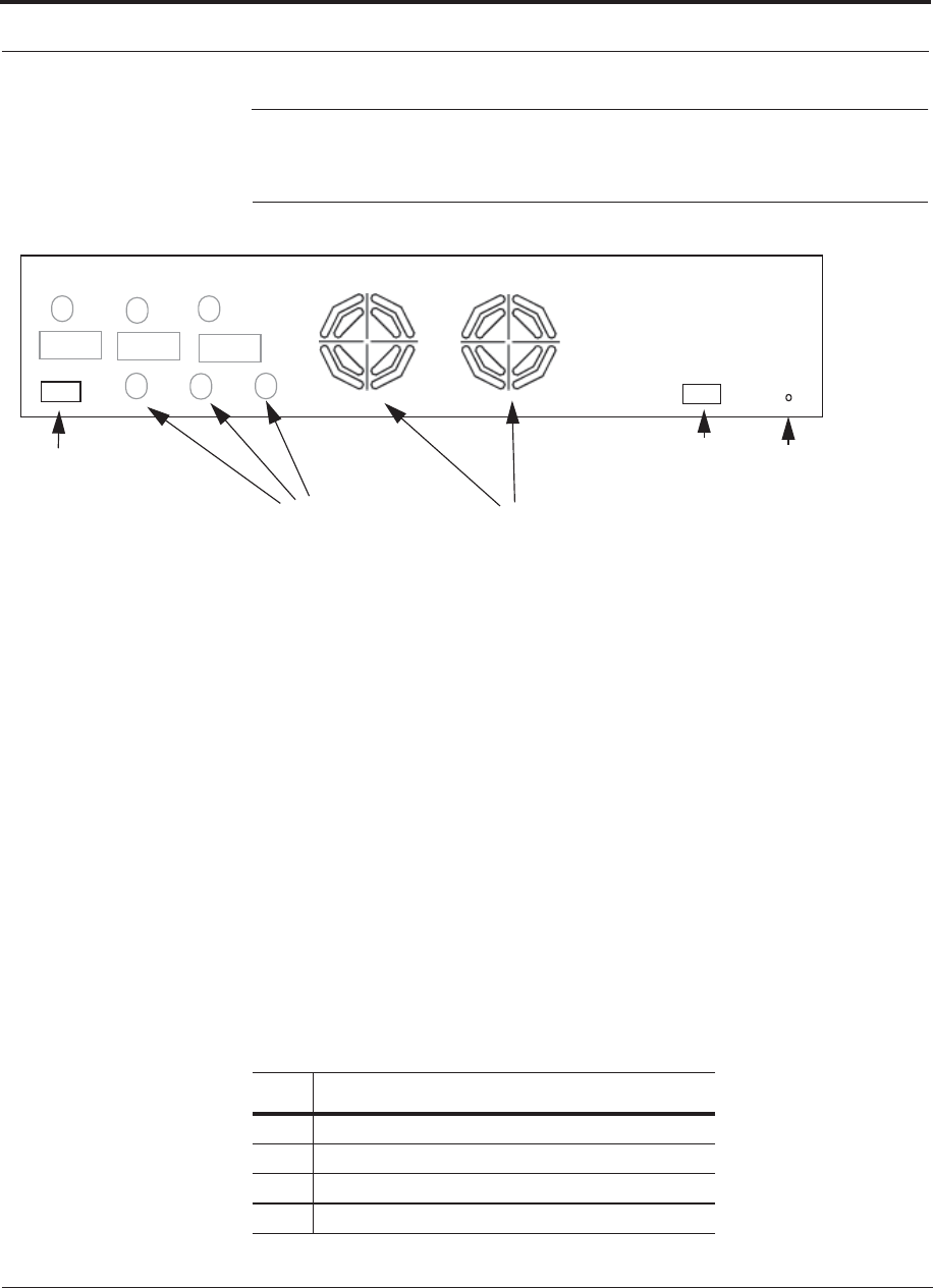
Fusion Wideband Main Hub Rear Panel
3-8 InterReach Fusion Wideband Installation, Operation, and Reference Manual
CONFIDENTIAL D-620616-0-20 Rev G
3.3 Fusion Wideband Main Hub Rear Panel
Figure 3-4 Fusion Wideband Main Hub Rear Panel
1
2
3
Band 1 Band 2 Band 3
UL1 UL2 UL3
DL1 DL2 DL3
45
AC Power
Alarms
1. AC power cord connector
2. Two air exhaust vents
3. Three N-type, female connectors for each band (Band 1, Band 2, and Band 3):
• Uplink (labeled UL1, UL2, and UL3)
• Downlink (labeled DL1, DL2, and DL3)
4. One 9-pin D-sub female connector for contact alarm monitoring (labeled
ALARMS)
5. Ground lug for connecting unit to frame ground (labeled GROUND)
3.3.1 Fusion Wideband Main Hub Rear Panel Connectors
3.3.1.1 9-pin D-sub Connector
The 9-pin D-sub connector (labeled ALARMS) provides a contact alarm for fault and
warning system alarm monitoring.
Table 3-3 lists the function of each pin on the 9-pin D-sub connector.
Table 3-3 9-pin D-sub Pin Connector Functions
Pin Function
1 Alarm Sense Input (DC Ground)
2 Alarm Sense Input 3
3 Alarm Sense Input 2
4 Warning Source Contact (positive connection)

Help Hot Line (U.S. only): 1-800-530-9960 3-9
D-620616-0-20 Rev G CONFIDENTIAL
Fusion Wideband Main Hub Rear Panel
This interface can both generate two source contact alarms (Fault and Warning) and
sense 3 single external alarm contacts (Alarm Sense Input 1 through 3).
3.3.1.2 N-type Female Connectors
There are two 50 Ohm N-type connector pairs for each of the 3 bands on the rear
panel of the Hub:
• The DOWNLINK connector receives downlink RF signals from a repeater, local
base station, or FlexWave Focus system.
• The UPLINK connector transmits uplink RF signals to a repeater, local base sta-
tion, or FlexWave Focus system.
CAUTION:The UPLINK and DOWNLINK ports cannot handle a DC power
feed from the local base station. If DC power is present, a DC block must be
used or the Fusion Wideband hub may be damaged.
5 Warning Source Contact (negative connection)
6 DC Ground (common)
7 Fault Source Contact (positive connection)
8 Alarm Sense Input 1
9 Fault Source Contact (negative connection)
Table 3-3 9-pin D-sub Pin Connector Functions
Pin Function

Main Hub Specifications
3-10 InterReach Fusion Wideband Installation, Operation, and Reference Manual
CONFIDENTIAL D-620616-0-20 Rev G
3.4 Main Hub Specifications
Table 3-4 Main Hub Specifications
Specification Description
Enclosure Dimensions (H u W u D)a:
a. Excluding angle brackets for the 19” rack mounting of the Hub.
89 mm x 438 mm x 381 mm (3.5 in. x 17.25 in. x 15 in.) 2U
Weight <5.5 kg (<12 lb)
Operating Temperature 0° to +45°C (+32° to +113°F)
Non-operating Temperature –20° to +85°C (–4° to +185°F)
Operating Humidity, non-condensing 5% to 95%
External Alarm Connector
(contact closure)
1 9-pin D-sub, female
Maximum: 40 mA @ 40V DC
Typical: 4 mA @ 12V DC
ADMIN/LAN Interface Connector 1 RJ-45, female
1 9-pin D-sub, male for optional modem
Fiber Connectors 4 Pair, SC/APCb
b. It is critical to system performance that only SC/APC fiber connectors are used throughout the fiber network, including
fiber distribution panels.
RF Connectors 4 Nc
c. 6 N, female connectors for FSN-W2-MH-1, FSN-W2-MH-2, and FSN-W2-MH-3
NOTE: The Fusion Wideband One Port Main Hub (PNs:
FSN-W1-MH-2-1P, FSN-W2-MH-3-1P, FSN-W3-MH-1P,
and FSN-W4-MH-1P) configuration is a cost reduced version
of the Fusion Wideband Main Hub and supports only one
Expansion Hub (up to 8 RAUs).
, female (50 Ohm), 1 Downlink/Uplink pair per band
LED Fault and Status Indicators Unit Status (1 pair):
•Power
• Main Hub Status
Downstream Unit/Link Status (1 per fiber port):
• Link/E-Hub/RAU
AC Power Rating 100/240V AC, 1A, 50-60 Hz
Operating Range: 90-132V AC/170-250V AC auto-ranging
Power Consumption (W) 30
MTBF 133,829 hours

Help Hot Line (U.S. only): 1-800-530-9960 3-11
D-620616-0-20 Rev G CONFIDENTIAL
Faults, Warnings, and Status Messages
3.5 Faults, Warnings, and Status Messages
3.5.1 Description
The Fusion Wideband Main Hub monitors and reports changes or events in system
performance to:
• Ensure that fiber receivers, amplifiers and IF/RF paths are functioning properly.
• Ensure that Expansion Hubs and Remote Access Units are connected and function-
ing properly.
An event is classified as fault, warning, or status message.
• Faults are service impacting.
• Warnings indicate a possible service impact.
• Status and informational messages are generally not service impacting.
The Fusion Wideband Main Hub periodically queries attached Expansion Hub and
Remote Access Units for their status. Both faults and warnings are reported to a con-
nected PC/laptop running a standard browser communicating with the Admin-
Browser software. Only faults are indicated by the faceplate LEDs.
For more information regarding the events, refer to:
• Appendix C for Main Hub faults.
• Appendix C for Main Hub warnings.
• Appendix C for Main Hub status messages.
• Section 9 for troubleshooting Main Hub LEDs.
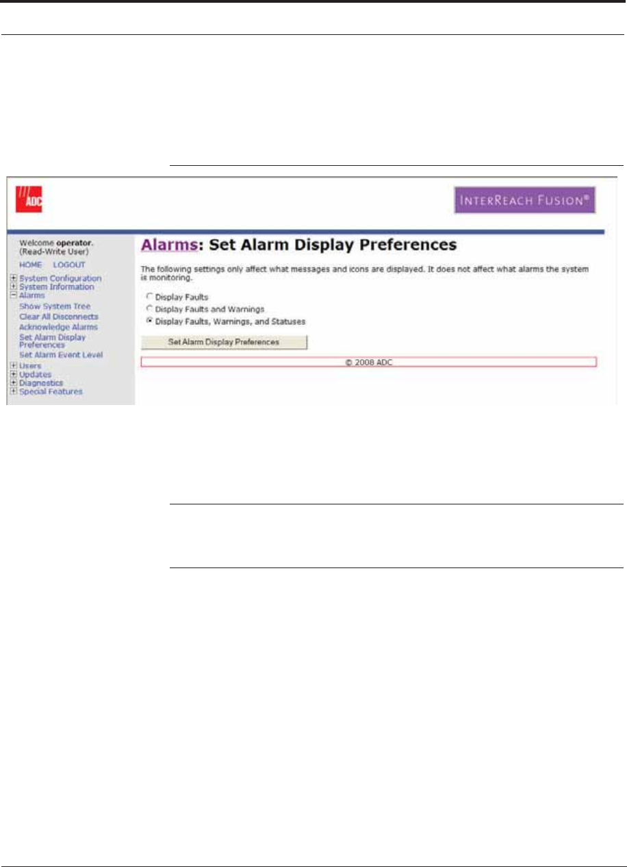
Faults, Warnings, and Status Messages
3-12 InterReach Fusion Wideband Installation, Operation, and Reference Manual
CONFIDENTIAL D-620616-0-20 Rev G
3.5.2 View Preference
AdminBrowser 1.0 or higher enables you to select (using the screen shown in
Figure 3-5) the type of events to be displayed.
Figure 3-5 Preferences Check Boxes
To modify the setting, using AdminBrowser, select Alarms J Set Alarm Preference
and select the desired choice. After you click OK, AdminBrowser refreshes and
updates the tree view according to the new setting.
NOTE: The setting is strictly visual and only in AdminBrowser. There is
no affect on the hardware itself. By default, the event filtering is set to
“Enable viewing of Faults only”.
The only exception to when the event filtering is ignored is during the Install/Config-
ure command. All events are displayed regardless of the event filtering setting. This
ensures a smooth installation.

InterReach Fusion Wideband Installation, Operation, and Reference Manual 4-1
D-620616-0-20 Rev G CONFIDENTIAL
SECTION 4 Fusion Wideband
Expansion Hub
This section contains the following subsections:
• Section 4.1 Expansion Hub Overview . . . . . . . . . . . . . . . . . . . . . . . . . . . . . . 4-1
• Section 4.2 Expansion Hub Front Panel . . . . . . . . . . . . . . . . . . . . . . . . . . . . . 4-3
• Section 4.3 Expansion Hub Rear Panel . . . . . . . . . . . . . . . . . . . . . . . . . . . . . . 4-8
• Section 4.4 Faults, Warnings, and Status Messages . . . . . . . . . . . . . . . . . . . . 4-9
• Section 4.5 Expansion Hub Specifications . . . . . . . . . . . . . . . . . . . . . . . . . . 4-10
4.1 Expansion Hub Overview
The Expansion Hub acts an interface between the Main Hub and the Remote Access
Unit(s) by converting optical signals to electrical signals and vice versa, as shown in
Figure 4-1. It also supplies control signals and DC power to operate the Remote
Access Unit(s) as well as passing status information from the RAUs to the Main Hub.
Figure 4-1 Expansion Hub in a Fusion Wideband System
Fusion Wideband Expansion Hub
Fusion Wideband Main Hub
RAU
Downlink Path: The Expansion Hub receives downlink (Band 1, 2, and 3) optical signals from the Main Hub using fiber
optic cable. It converts the signals to electrical and sends them to up to eight Remote Access Units (RAUs) using CATV
cables. The Expansion Hub also receives configuration information from the Main Hub using the fiber optic cable and
relays it to the RAUs using CATV cable.
Uplink Path: The Expansion Hub receives uplink (Band 1, 2, and 3) IF signals from up to eight RAUs using CATV cables.
It converts the signals to optical and sends them to a Main Hub using fiber optic cable.
The Expansion Hub also receives RAU status information using CATV cable and sends it and its own status information to
the Main Hub using the fiber optic cable.
Downlink to Expansion Hub
Uplink from Expansion Hub
Downlink from Expansion Hub
Uplink to Expansion Hub
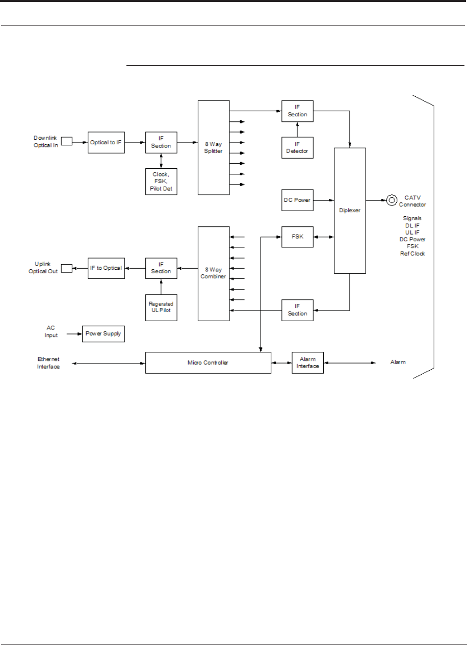
Expansion Hub Overview
4-2 InterReach Fusion Wideband Installation, Operation, and Reference Manual
CONFIDENTIAL D-620616-0-20 Rev G
Figure 4-2 Expansion Hub Block Diagram
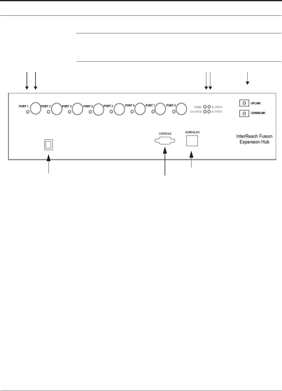
Help Hot Line (U.S. only): 1-800-530-9960 4-3
D-620616-0-20 Rev G CONFIDENTIAL
Expansion Hub Front Panel
4.2 Expansion Hub Front Panel
Figure 4-3 Expansion Hub Front Panel
1 2 3 4 5
86
7
1. One port LED per type F connector port for link status and downstream RAU sta-
tus (8 pair total).
2. Eight CATV cable, type F connectors (labeled PORT 1, 2, 3, 4, 5, 6, 7, 8)
3. One pair of unit status LEDs
• One LED for unit power status (labeled POWER)
• One LED for unit status (labeled E-HUB STATUS)
4. One set of fiber connection status LEDs
• One LED for fiber downlink status (labeled DL STATUS)
• One LED for fiber uplink status (labeled UL STATUS)
5. One fiber optic port which has two connectors
• One standard female SC/APC connector for MMF/SMF output (labeled
UPLINK)
• One standard female SC/APC connector for MMF/SMF input (labeled
DOWNLINK)
6. One 9-pin D-sub male connector for TE factory testing (labeled CONSOLE)
7. One RJ-45 female connector for system communication and diagnostics using a
PC/laptop with direct connect or using a LAN switch (labeled ADMIN/LAN)
8. Power Switch

Expansion Hub Front Panel
4-4 InterReach Fusion Wideband Installation, Operation, and Reference Manual
CONFIDENTIAL D-620616-0-20 Rev G
4.2.1 75 Ohm Type F Connectors
The eight type F connectors on the Expansion Hub are for the CATV cables used to
transmit and receive signals to and from RAUs. Use only 75 ohm type F connectors
on the CATV cable.
The CATV cable also delivers DC electrical power to the RAUs. The Expansion
Hub’s DC voltage output is 54V DC nominal. A current limiting circuit protects the
Hub if any port draws excessive power.
NOTE: For system performance, it is important to use only low loss solid cop-
per center conductor CATV cable with quality type F connectors that use captive
centerpin connectors. Refer to Appendix A for approved cables and connectors.
4.2.2 Manufacturing RS-232 Serial Connector
Console Port
This console port is only used by TE manufacturing test purposes. DO NOT CON-
NECT ANYTHING TO IT.
Local Monitoring
Use a crossover Ethernet cable (PN-4069-ADB) to directly connect a laptop or PC to
the RJ-45 female connector for local monitoring or configuring the Expansion Hub
and associated RAUs using the AdminBrowser-EH resident software. The cable typi-
cally has a RJ-45 male connector on both ends. Refer to Appendix A.5 on page A-8
for the cable pinout and the AdminBrowser manual.
4.2.3 Optical Fiber Uplink/Downlink Connectors
The optical fiber uplink/downlink port transmits and receives optical signals between
the Expansion Hub and the Main Hub using industry-standard SMF or MMF cable.
The fiber port has two female SC/APC connectors:
• Optical Fiber Uplink Connector
This connector (labeled UPLINK) is used to transmit (output) uplink optical signals
to the Main Hub.
• Optical Fiber Downlink Connector
This connector (labeled DOWNLINK) is used to receive (input) downlink optical sig-
nals from the Main Hub.
CAUTION: To avoid damaging the Expansion Hub’s fiber connector
ports, use only SC/APC fiber cable connectors. Additionally, use only
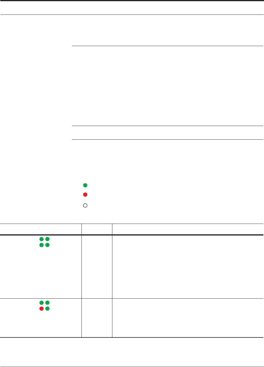
Help Hot Line (U.S. only): 1-800-530-9960 4-5
D-620616-0-20 Rev G CONFIDENTIAL
Expansion Hub Front Panel
SC/APC fiber connectors throughout the fiber network, including fiber distribu-
tion panels. This is critical for ensuring system performance.
4.2.4 LED Indicators
The unit’s front panel LEDs indicate fault conditions and commanded or fault lockouts.
The LEDs do not indicate warnings or whether the system test has been performed.
Only use the LEDs to provide basic information or as a backup when you are not using
AdminBrowser.
Upon power up, the Expansion Hub goes through a five-second test to check the LED
lamps. During this time, the LEDs blink through the states shown in Table 4-2, letting
you visually verify that the LED lamps and the firmware are functioning properly.
NOTE: Refer to Section 9 for troubleshooting using the LEDs.
Unit Status and DL/UL Status LEDs
The Expansion Hub unit status and DL/UL status LEDs can be in one of the states
shown in Table 4-1. These LEDs can be:
steady green
steady red
off
Table 4-1 Expansion Hub Unit Status and DL/UL Status LED States
LED State Indicates
POWER
EH STATUS DL STATUS
UL STATUS
Green / Green
Green / Green
• The Expansion Hub is connected to power and all power supplies are
operating.
• The Expansion Hub is not reporting a fault or lockout condition; but
the system test may need to be performed or a warning condition
could exist (use AdminManager to determine this).
• Optical power received is above minimum (the Main Hub is con-
nected) although the cable optical loss may be greater than recom-
mended maximum.
• Optical power transmitted (uplink laser) is normal and communica-
tions with the Main Hub are normal.
POWER
EH STATUS DL STATUS
UL STATUS
Green / Green
Red / Green
• Optical power received is above minimum (the Main Hub is con-
nected) although the cable optical loss may be greater than recom-
mended maximum.
• Optical power transmitted (uplink laser) is normal and communica-
tions with the Main Hub are normal.
• The Expansion Hub is reporting a fault.

POWER
EH STATUS DL STATUS
UL STATUS
Expansion Hub Front Panel
4-6 InterReach Fusion Wideband Installation, Operation, and Reference Manual
CONFIDENTIAL D-620616-0-20 Rev G
Green / Green
Green / Green
(60-ppm)
• Optical power received is above minimum (the Main Hub is con-
nected) although the cable optical loss may be greater than recom-
mended maximum.
• Optical power transmitted (uplink laser) is normal and communica-
tions with the Main Hub are normal.
• The Expansion Hub is reporting a commanded lockout.
POWER
EH STATUS DL STATUS
UL STATUS
Green / Red
Red / Green
Green / Red
(60-ppm)
• A fault condition was detected, optical power received is below mini-
mum.
• The Main Hub is not connected, is not powered, or the Main Hub’s
downlink laser has failed, or the downlink fiber is disconnected or
damaged.
• An optical signal was detected, but there has been no valid communi-
cation from the MH in the preceeding 90 seconds.
POWER
EH STATUS DL STATUS
UL STATUS
Green / Green
Red / Red
Red / Red
(60-ppm)
• The Expansion Hub is reporting a fault condition.
• Optical power received is above minimum (Main Hub is connected)
although the cable optical loss may be greater than recommended
maximum.
• Optical power transmitted is below minimum (Expansion Hub uplink
laser has failed; unable to communicate with Main Hub). UL STATUS
LED state must be checked within the first 90 seconds after power on.
If initially green, then red after 90 seconds, it means that there is no
communication with the Main Hub. If red on power up, replace the
Expansion Hub.
• No optical faults have been detected, but no valid message was
received from the MH in the preceeding 90 seconds.
POWER
EH STATUS DL STATUS
UL STATUS
Green / Red
Red / Red
• Optical power received is below minimum (the Main Hub is not con-
nected, is not powered, or the Main Hub’s downlink laser has failed,
or the downlink fiber is disconnected or damaged.)
• Optical power transmitted is below minimum (the Expansion Hub
uplink laser has failed; is unable to communicate with the Main Hub).
UL STATUS LED state must be checked within the first 90 seconds
after power on. If initially green, then red after 90 seconds, it means
that there is no communication with the Main Hub. If red on power
up, the uplink laser has failed, replace the Expansion Hub.
POWER
EH STATUS DL STATUS
UL STATUS
Green /Off
Green / Off
• Expansion Hub is in factory test mode, return it to the factory.
POWER
EH STATUS DL STATUS
UL STATUS
Red/ Don’t
Care
Red/ Don’t
Care
• One or more power supplies are out of specification. The hub needs to
be replaced.
POWER
EH STATUS DL STATUS
UL STATUS
Green/ Red
Off/ Off
• Expansion Hub failure. The Hub must be replaced.
Table 4-1 Expansion Hub Unit Status and DL/UL Status LED States
LED State Indicates
Help Hot Line (U.S. only): 1-800-530-9960 4-7
D-620616-0-20 Rev G CONFIDENTIAL
Expansion Hub Front Panel
RJ-45 Port LEDs
The Expansion Hub has a port LED, labeled PORT, for each of the eight 75 Ohm,
Type F ports. The port LEDs can be in one of the states shown in Table 4-2. These
LEDs can be:
off
steady green
steady red
flashing red (60 pulses per minute [PPM])
Table 4-2 Fusion Wideband Expansion Hub Port LED States
LED State Indicates
Off • The RAU is not connected.
Green
• The RAU is connected.
• No faults from the RAU.
Red
(60 PPM)
• The RAU was disconnected.
• The RAU is not communicating.
• The RAU port power is tripped.
Red
(Steady)
• The RAU is disconnected.
• The RAU is reporting a fault.
Green
(60-ppm)
• The RAU is disconnected.
• The RAU is reporting a lockout condition.
PORT
PORT
PORT
PORT
PORT
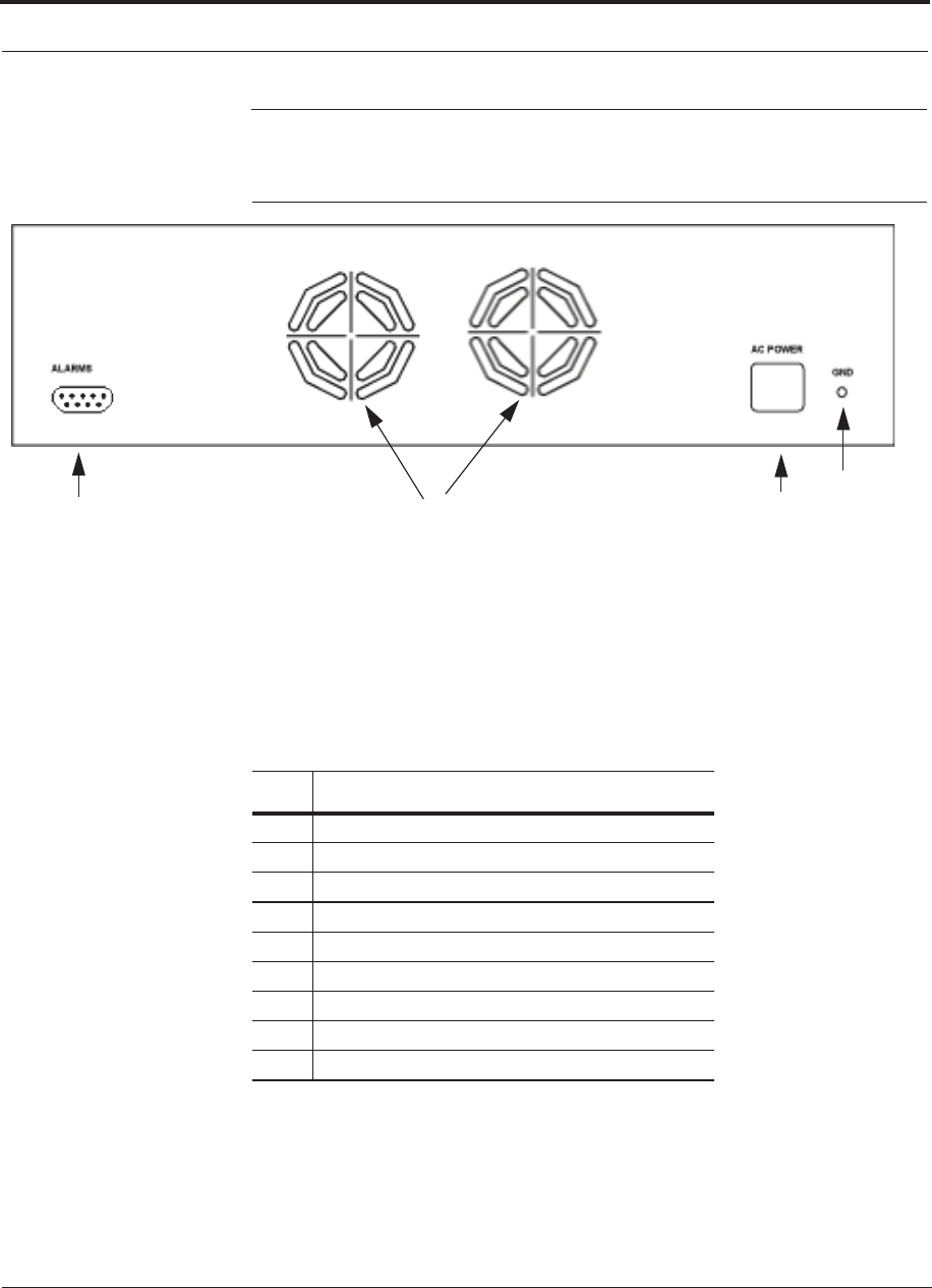
Expansion Hub Rear Panel
4-8 InterReach Fusion Wideband Installation, Operation, and Reference Manual
CONFIDENTIAL D-620616-0-20 Rev G
4.3 Expansion Hub Rear Panel
Figure 4-4 Expansion Hub Rear Panel
1234
1. AC power cord connector
2. Two air exhaust vents
3. One 9-pin D-sub female connector for contact alarm monitoring (labeled
ALARMS)
4. Ground lug for connecting unit to frame ground (labeled GROUND)
Table 4-3 9-pin D-sub Pin Connector Functions
Pin Function
1 Alarm Sense Input (DC Ground)
2 Alarm Sense Input 3
3 Alarm Sense Input 2
4N/C
5N/C
6 DC Ground (common)
7N/C
8 Alarm Sense Input 1
9N/C
This interface can monitor three single external alarm contacts (Alarm Sense Input 1
This interface monitors the output contact closures from a Universal Power Supply
(UPS). Verify the output contact closure state (normally closed or normally open) of
the UPS, and set the appropriate contact definition using AdminBrowser.
• Faults are service impacting.

Help Hot Line (U.S. only): 1-800-530-9960 4-9
D-620616-0-20 Rev G CONFIDENTIAL
Faults, Warnings, and Status Messages
• Warnings indicate a possible service impact.
• Status messages are generally not service impacting.
4.4 Faults, Warnings, and Status Messages
Both fault and warning conditions of the Expansion Hub and attached RAUs are
reported to the Main Hub. Only faults are indicated by LEDs.
For more information, refer to Appendix C, “Faults, Warnings, Status Tables,” on
page C-1.
NOTE: You can select what type of events AdminBrowser displays. Refer
to Section 3.5.2 View Preference 3-12.

Expansion Hub Specifications
4-10 InterReach Fusion Wideband Installation, Operation, and Reference Manual
CONFIDENTIAL D-620616-0-20 Rev G
4.5 Expansion Hub Specifications
Table 4-4 Expansion Hub Specifications
Specification Description
Enclosure Dimensions (H u W u D) 89 mm x 438 mm x 381 mm
(3.5 in. x 17.25 in. x 15 in.) 2U
Weight < 6.6 kg (< 14.5 lb.)
Operating Temperature 0° to +45°C (+32° to +113°F)
Non-operating Temperature –20° to +85°C (–4° to +185°F)
Operating Humidity, non-condensing 5% to 95%
CATV Connectorsa
a. It is important that you use only recommended CATV 75 Ohm cable with quality F connectors.
8 F, female (CATV - 75 Ohm)
Fiber Connectorsb
b. It is critical to system performance that only SC/APC fiber connectors are used throughout the fiber network, including
fiber distribution panels.
1 Pair, SC/APC
LED Alarm and Status Indicators Unit Status (1 pair):
•Power
• E-Hub Status
Fiber Link Status (1 pair):
• DL Status
• UL Status
Port Status (1 pair per CATV port):
• Link/RAU
External Alarm Connector (contact sense
monitor)
1 9-pin D-sub, female
AC Power (Volts) (47–63 Hz) Rating: 100/240V AC, 6A, 50-60 Hz
Operating Range: 90-132V AC/170-250V AC auto-ranging
Power Consumption (W) 4 RAUs: 290 typical, 360 max.
8 RAUs: 500 typical, 630 max.
MTBF 54,539 hours

InterReach Fusion Wideband Installation, Operation, and Reference Manual 5-1
D-620616-0-20 Rev G CONFIDENTIAL
SECTION 5 Remote Access Unit
This section contains the following subsections:
• Section 5.1 RAU Overview 5-1
• Section 5.2 Remote Access Unit Connectors . . . . . . . . . . . . . . . . . . . . . . . . . 5-6
• Section 5.3 RAU LED Indicators . . . . . . . . . . . . . . . . . . . . . . . . . . . . . . . . . . 5-6
• Section 5.4 Faults and Warnings . . . . . . . . . . . . . . . . . . . . . . . . . . . . . . . . . . . 5-7
• Section 5.5 Remote Access Unit Specifications . . . . . . . . . . . . . . . . . . . . . . . 5-8
5.1 RAU Overview
The Remote Access Unit (RAU) is an active transceiver that connects to an Expan-
sion Hub using industry-standard CATV cable, which delivers RF signals, configura-
tion information, and electrical power to the RAU.
An RAU passes converted IF to RF (Downlink) and converted RF to IF (Uplink) sig-
nals between an Expansion Hub and an attached passive antenna where the signals
are transmitted to wireless devices as shown in Figure 5-1.
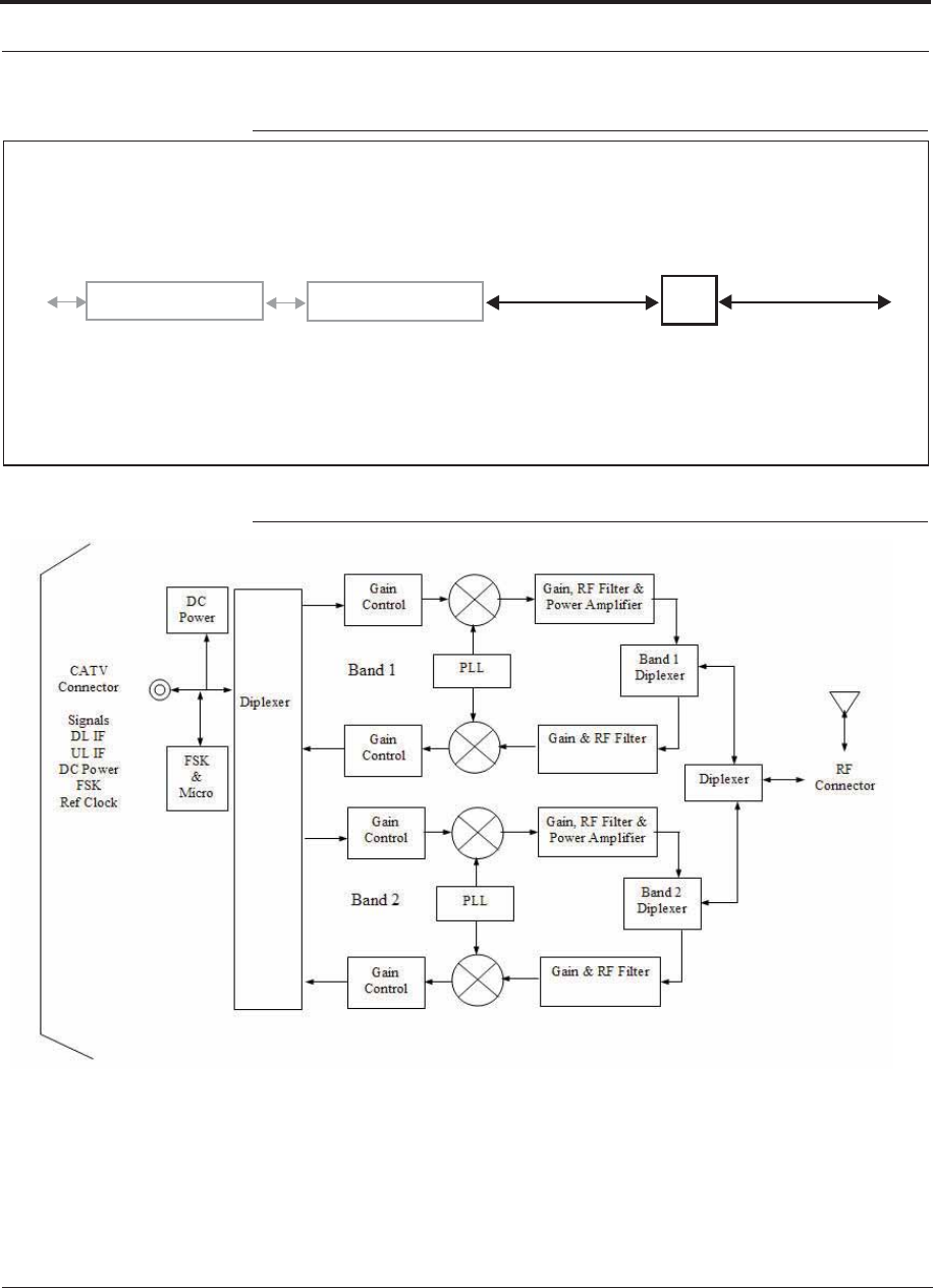
RAU Overview
5-2 InterReach Fusion Wideband Installation, Operation, and Reference Manual
CONFIDENTIAL D-620616-0-20 Rev G
Figure 5-1 Remote Access Unit in a Fusion Wideband System
Fusion Wideband Expansion Hub RAU
Downlink Path: The RAU receives downlink IF signals from a Fusion Wideband Hub using 75 Ohm CATV cable. It con-
verts the signals to RF and sends them to a passive RF antenna using 50 Ohm coaxial cable. Also, the RAU receives con-
figuration information from the Fusion Wideband Hub using the 75 Ohm CATV cable.
Uplink Path: The RAU receives uplink RF signals from a passive RF antenna using 50 Ohm coaxial cable. It converts the
signals to IF and sends them to a Fusion Wideband Hub using 75 Ohm CATV cable. Also, the RAU sends its status infor-
mation to the Fusion Wideband Hub using CATV cable.
The RAU receives 54VDC power from the Fusion Wideband Hub port through the 75 Ohm CATV cable center pin.
Downlink to RAU
Uplink from RAU
Fusion Wideband Main Hub
Downlink to antenna
Uplink from antenna
Figure 5-2 Remote Access Unit Block Diagram
, 3*
(Multiband)
* For FSN-W2-808519-1 RAU when Band 3 is active.

Help Hot Line (U.S. only): 1-800-530-9960 5-3
D-620616-0-20 Rev G CONFIDENTIAL
RAU Overview
The Fusion Wideband RAUs are manufactured to a specific set of bands: one 60 MHz
Band 1 (split into two sub-bands 1A and 1B for the FSN-W2-808519-1 RAU), and
one 75 MHz Band 2. Table 5-1 lists the Fusion Wideband RAUs, the Fusion Wide-
band Band, and the frequency bands they cover.
Table 5-1 Frequency Bands Covered by Fusion Wideband RAUs
Fusion Wideband RAU Part Number
Fusion
Wide-
band
Band
RF Passband
Downlink
(MHz) Uplink
(MHz)
MAIN
HUB/
RAU
Band
RAU
Band-
width
2100/1800 FSN-W1-2118-1 2100 2110-2170 1920-1980 1 60 MHz
1800 1805-1880 1710-1785 2 75 MHz
2100 High Power
(single-band RAU)
FSN-W1-21HP-1 2100 2110-2170 1920-1980 1 60 MHz
1900/AWS FSN-W1-1921-1 1900
(A-F)
1930-1990 1850-1910 1 60 MHz
AWS 2110-2155 1710-1755 2 45 MHz
800/850/1900 FSN-W2-808519-1 800 851-869 806-824 1
(sub-band
1A)
18 MHz
850 869-894 824-849 3
(sub-band
1B)
25 MHz
1900
(A-F)
1930-1990 1850-1910 2 60 MHz
700/AWS FSN-W2-7021-1 700
(Upper C)
746-757 776-787 1
(sub-band
1A)
11 MHz
700
(Lower
ABC)
728-746 698-716 3
(sub-band
1B)
18 MHz
AWS 2110-2155 1710-1755 2 45 MHz
700/700 MIMO (Upper C) FSN-W2-7575-1 700
(Upper C)
746-757 776-787 1 (sub-
band 1A)
11 MHz
700
(Upper C)
746-757 776-787 3 (sub-
band 1B)
11 MHz
700/700 MIMO (Lower ABC) FSN-W2-7070-1 700
(Lower
ABC)
728-746 698-716 1 (sub-
band 1A)
18 MHz
700
(Lower
ABC)
728-746 698-716 3 (sub-
band 1B)
18 MHz

RAU Overview
5-4 InterReach Fusion Wideband Installation, Operation, and Reference Manual
CONFIDENTIAL D-620616-0-20 Rev G
700 ABC/AWS HP/AWS HP FSN-W4-702121-1-HP AWS 2110-2155 1710-1755 1
(sub-band
1A)
45 MHz
700
(Lower
ABC)
728-746 698-716 3
(sub-band
1B)
18 MHz
AWS 2110-2155 1710-1755 2 45 MHz
700 UC/AWS HP/AWS HP FSN-W4-752121-1-HP AWS 2110-2155 1710-1755 1
(sub-band
1A)
45 MHz
700
(Upper C)
746-757 776-787 3
(sub-band
1B)
11 MHz
AWS 2110-2155 1710-1755 2 45 MHz
2500/2500 FSN-2500-2-WMAX 2500 2496-2690 2496-2690 1 30 MHz
2500 2496-2690 2496-2690 2 30 MHz
2600/2600 FSN-W3-2626-1 2600 2620-2690 2500-2570 1 70 MHz
2600 2620-2690 2500-2570 2 70 MHz
Table 5-1 Frequency Bands Covered by Fusion Wideband RAUs (continued)
Fusion Wideband RAU Part Number
Fusion
Wide-
band
Band
RF Passband
Downlink
(MHz) Uplink
(MHz)
MAIN
HUB/
RAU
Band
RAU
Band-
width

Table 5-2 System Gain (Loss) Relative to CATV Cable Length
Cable
Type
Comm-
Scope
Part
Number Plenum
Rated
Solid
Copper
Conductor
Copper
Clad
Conductor
Zero-loss
RF
Maximum
Length
(meters)
Distance
RF is
10dB
Below
Input RF
(meters)
RG-59
2065V Yes X 130 180
2022V Yes X 100 100*
5572R No X 95 95*
5565 No X 130 180
2279V Yes X 140 190
2275V Yes X 140 150*
5726 No X 140 140*
5765 No X 140 190
RG-11
2293K Yes X 235 320
2285K Yes X 235 300*
5913 No X 235 300*
Help Hot Line (U.S. only): 1-800-530-9960 5-5
D-620616-0-20 Rev G CONFIDENTIAL
RAU Overview
* Exceeding the distance of copper-clad cable will result in the attached RAU becoming
non-functional. If the distance of a cable run is at its maximum and is of concern, TE recom-
mends the use of solid copper cable to ensure successful operation.
RG-6

Remote Access Unit Connectors
5-6 InterReach Fusion Wideband Installation, Operation, and Reference Manual
CONFIDENTIAL D-620616-0-20 Rev G
5.2 Remote Access Unit Connectors
5.2.1 50 Ohm Type-N Connector
The RAU has one female type-N connector (two female type-N connectors for
FSN-W1-1921-1, FSN-W2-808519-1, FSN-W2-7070-1, FSN-W2-7575-1,
FSN-W3-2626-1, FSN-W4-702121-1-HP, FSN-W4-752121-1-HP and
FSN-2500-2-WMAX RAUs). The connector is a duplexed RF input/output port that
connects to a standard 50: passive antenna using coaxial cable.
5.2.2 75 Ohm Type-F Connector
The RAU has one type-F female connector that connects it to a Fusion Wideband
Hub using CATV 75 Ohm cable. Use RG-59, 6, or 11 solid copper center conductor
cables.
NOTE: For system performance, it is important that you use only low loss,
solid copper center conductor CATV cable with quality F connectors that use
captive centerpin conductors. Refer to Appendix A for specific information.
5.3 RAU LED Indicators
Upon power up, the RAU goes through a two-second test to check the LED lamps.
During this time, the LEDs blink green/green red/red, letting you visually verify that
the LED lamps and the firmware are functioning properly.
NOTE: Refer to Section 9 for troubleshooting using the LEDs.
Status LEDs
The RAU status LEDs can be in one of the states shown in Table 5-3. These LEDs
can be:
off
steady green
steady red
There is no off state when the unit’s power is on.

Table 5-3 Remote Access Unit LED States
LED State Indicates
LINK
ALARM Off
Off
• The RAU is not receiving DC power.
LINK
ALARM Green
Green
• The RAU is powered and is not indicating a fault
condition. Communication with the Fusion
Wideband Hub is normal; however, the system
test may need to be performed or a warning con-
dition may exist (use AdminBrowser to deter-
mine this).
LINK
ALARM Green
Red
• The RAU is indicating a fault or lockout condi-
tion, but communication with the Fusion Wide-
band Hub is normal.
LINK
ALARM Red
Red
• The RAU is reporting a fault and is not able to
communicate with the Fusion Wideband Hub
LINK
ALARM Green (60-ppm)
Green (60-ppm)
• The RAU is reporting a lockout condition, but
communication with the Fusion Wideband Hub
is normal.
Help Hot Line (U.S. only): 1-800-530-9960 5-7
D-620616-0-20 Rev G CONFIDENTIAL
Faults and Warnings
5.4 Faults and Warnings
Both fault and warning conditions are reported to the Fusion Wideband Hub where
they are stored. Only faults are indicated by the faceplate LEDs.
For more information, refer to Appendix C.

Remote Access Unit Specifications
5-8 InterReach Fusion Wideband Installation, Operation, and Reference Manual
CONFIDENTIAL D-620616-0-20 Rev G
5.5 Remote Access Unit Specifications
Table 5-4 Remote Access Unit Specifications
Specification Description
Dimensions (H u W u D) 54 mm × 286 mm × 281 mm
(2.13 in. × 11.25 in. × 11.13 in.)
Weight < 2.1 kg (< 4.6 lb.)
Operating Temperature –25° to +45°C (–13° to +113°F)
Non-operating Temperature –25° to +85°C (–13° to +185°F)
Operating Humidity, non-condensing 5% to 95%
RF Connectors One Type-F, female (CATV - 75 ohms)
One Type-N, femalea
a. Two type N female connectors for FSN-W1-1921-1, FSN-W2-808519-1, FSN-W2-7070-1,
FSN-W2-7575-1, FSN-W3-2626-1, FSN-W4-702121-1-HP, FSN-W4-752121-1-HP, and
FSN-2500-2-WMAX RAUs.
(coaxial 50 ohms)
LED Alarm and Status Indicators Unit Status (1 pair):
• Link
• Alarm
Maximum Heat Dissipation (W) 50 typical, 64 max (from the Hub)
MTBF 202,684 hours
NOTE: For system performance, it is important that you use only low loss,
solid copper center conductor CATV cable with quality F connectors that use
captive centerpin conductors. Refer to Appendix A for more information.

InterReach Fusion Wideband Installation, Operation, and Reference Manual 6-1
D-620616-0-20 Rev G CONFIDENTIAL
SECTION 6 Designing a
Fusion Wideband Solution
This section contains the following subsections:
• Section 6.1 Overview 6-1
• Section 6.2 Downlink RSSI Design Goal . . . . . . . . . . . . . . . . . . . . . . . . . . . . 6-3
• Section 6.3 Maximum Output Power per Carrier . . . . . . . . . . . . . . . . . . . . . . 6-4
• Section 6.4 System Gain . . . . . . . . . . . . . . . . . . . . . . . . . . . . . . . . . . . . . . . . 6-16
• Section 6.5 Estimating RF Coverage . . . . . . . . . . . . . . . . . . . . . . . . . . . . . . 6-18
• Section 6.6 Link Budget Analysis . . . . . . . . . . . . . . . . . . . . . . . . . . . . . . . . . 6-26
• Section 6.7 Optical Power Budget . . . . . . . . . . . . . . . . . . . . . . . . . . . . . . . . 6-38
• Section 6.8 Connecting a Main Hub to a Base Station . . . . . . . . . . . . . . . . . 6-39
6.1 Overview
Designing a Fusion Wideband solution is a matter of determining coverage and
capacity needs. This requires the following steps:
1. Determine the wireless service provider’s requirements: Refer to Section 6.2,
“Downlink RSSI Design Goal,” on page 6-3.
The following information is typically provided by the service provider:
• Frequency (for example, 1900 MHz)
• Band (for example, “A-F” band in the PCS spectrum)
• Protocol (for example, CDMA, GSM, 1xRTT, GPRS, and so on)
• Number of sectors and peak capacity per sector (translates to the number of RF
carriers that the system will have to transmit)
• Downlink RSSI design goal (RSSI, received signal strength at the wireless
handset, for example, –85 dBm)

Overview
6-2 InterReach Fusion Wideband Installation, Operation, and Reference Manual
CONFIDENTIAL D-620616-0-20 Rev G
The design goal is always a stronger signal than the mobile phone needs. It
includes inherent factors which affect performance.
• RF source (base station or bidirectional amplifier or repeater), type of equip-
ment if possible.
2. Determine the downlink power per carrier from the RF source through the
DAS: Refer to Section 6.3, “Maximum Output Power per Carrier,” on page
6-4.
The maximum power per carrier is a function of modulation type, the number of
RF carriers, signal quality issues, regulatory emissions requirements, and Fusion
Wideband’s RF performance. Power per carrier decreases as the number of carri-
ers increases.
3. Develop an RF link budget: Refer to Section 6.5, “Estimating RF Coverage,”
on page 6-18.
Knowing both the power per carrier and RSSI design goal, you can develop an RF
downlink link budget which estimates the allowable path loss from an RAU’s
antenna to the wireless handset.
allowable path loss = power per carrier + antenna gain – design goal
Satisfactory performance can be expected as long as path loss is below this level.
4. Determine the in-building environment: Refer to Section 6.5, “Estimating RF
Coverage,” on page 6-18.
• Determine which areas of the building require coverage (entire building, public
areas, parking levels, and so on.)
• Obtain floor plans to determine floor space of building and the wall layout of
the proposed areas to be covered. Floor plans are also useful when you are
selecting antenna locations.
• If possible, determine the building’s construction materials (sheetrock, metal,
concrete, and so on.)
• Determine the type of environment:
– Open layout (for example, a convention center)
– Dense, close walls (for example, a hospital)
– Mixed use (for example, an office building with hard wall offices and cubi-
cles)
5. Determine the appropriate estimated path loss slope that corresponds to the
type of building and its layout, and estimate the coverage distance for each
RAU: Refer to Section 6.5, “Estimating RF Coverage,” on page 6-18.
Use the path loss slope (PLS), which gives a value to the RF propagation charac-
teristics within the building, to convert the RF link budget into an estimate of the
coverage distance per antenna. This helps establish the quantities of Fusion Wide-
band equipment you need. The actual path loss slope that corresponds to the spe-
cific RF environment inside the building can also be determined empirically by
performing an RF site-survey of the building. This involves transmitting a cali-

Help Hot Line (U.S. only): 1-800-530-9960 6-3
D-620616-0-20 Rev G CONFIDENTIAL
Downlink RSSI Design Goal
brated tone for a fixed antenna and making measurements with a mobile antenna
throughout the area surrounding the transmitter.
6. Determine the items required to connect to the base station: Refer to
Section 6.8, “Connecting a Main Hub to a Base Station,” on page 6-39.
Once you know the quantities of Fusion Wideband equipment to be used, you can
determine the accessories (combiners/dividers, surge suppressors, repeaters,
attenuators, circulators, and so on.) required to connect the system to the base sta-
tion.
The individual elements that must be considered in designing a Fusion Wideband
solution are explained in the following sections.
NOTE: Access the TE Customer Portal at http://www.te.com/adc for
on-line dimensioning and design tools.
6.2 Downlink RSSI Design Goal
Wireless service providers typically provide a minimum downlink signal level and an
associated confidence factor when specifying coverage requirements. These two fig-
ures of merit are a function of wireless handset sensitivity and margins for fading and
body loss. Wireless handset sensitivity is the weakest signal that the handset can pro-
cess reliably and is a combination of the thermal noise in the channel, noise figure of
the handset receiver front end and minimum required SNR. Fade margins for mul-
tipath fading (fast or small-scale) and log-normal shadow fading (slow or large-scale)
are determined by the desired confidence factor, and other factors. Downlink RSSI
design goal calculations for the GSM protocol are shown below for a 95% area cover-
age confidence factor.
Noise Power
10 Log (KT)+10 Log (200 KHz); K=1.38X10⁻²³, T=300 degrees Kelvin
–121 dBm
Wireless Handset Noise Figure 8 dB
Required SNR 9 dB
Multipath Fade Margin
95% Reliability for Rician K=6 dB
6dB
Log-normal Fade Margin
95% Area/87% Edge Reliability for 35 dB PLS and 9 dB Sigma
10 dB
Body Attenuation + 3 dB
Downlink RSSI Design Goal (PDesignGoal)
Signal level received by wireless handset at edge of coverage area
–85 dBm

Maximum Output Power per Carrier
6-4 InterReach Fusion Wideband Installation, Operation, and Reference Manual
CONFIDENTIAL D-620616-0-20 Rev G
Downlink design goals on the order of –85 dBm are typical for protocols, such as
GSM. Wireless service providers may choose a higher level to ensure that in-building
signal dominates any macro signal that may be leaking into the building.
6.3 Maximum Output Power per Carrier
The following tables show the recommended maximum power per carrier out of the
RAU 50 Ohm Type-N connector for different frequencies, protocols, and numbers of
carriers. These maximum levels are dictated by RF signal quality and regulatory
emissions issues. In general, as the number of RF carrier increases, the maximum
power per carrier decreases. If these levels are exceeded, signal quality will be
degraded and/or regulator requirements will be violated. The maximum input power
to the Hub is determined by subtracting the system gain from the maximum output
power of the RAU. System gain is software selectable from 0 dB to 15 dB in 1 dB
steps. Additionally, both the uplink and downlink gain of each RAU can be attenuated
0 or 10 dB.
When connecting a Hub to a base station or repeater, attenuation on the downlink is
typically required to avoid exceeding Fusion Wideband’s maximum output power
recommendations.
WARNING: Exceeding the maximum input power may cause perma-
nent damage to the Hub. Do not exceed the maximum composite input
power of 1W (+30 dBm) to the Hub at any time.
NOTE: These specifications are for downlink power at the RAU output (excluding
antenna).
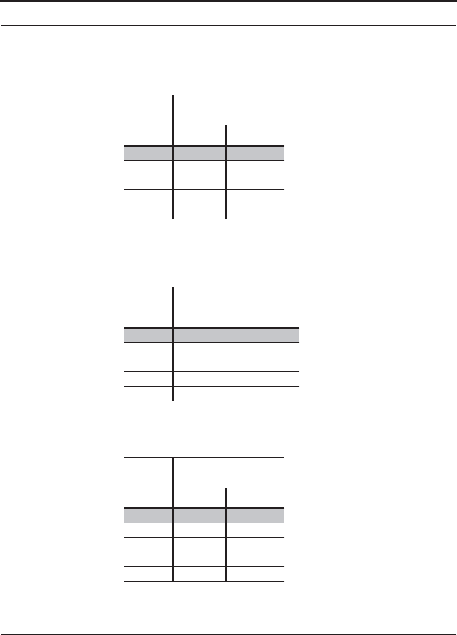
Help Hot Line (U.S. only): 1-800-530-9960 6-5
D-620616-0-20 Rev G CONFIDENTIAL
Maximum Output Power per Carrier
6.3.1 700/AWS RAU
Table 6-1 700 MHz (Lower A, B, C) Power per Carrier
No. of
Carriers
Power per Carrier
(dBm)
WCDMA LTE
1 14.0 14.0
2 11.0 11.0
3 9.0 9.0
4 8.0 8.0
5 7.0 7.0
Note: Operation at or above these output power levels may pre-
vent Fusion Wideband from meeting RF performance specifica-
tions or FCC Part 15 and EN55022 emissions requirements.
Table 6-2 700 MHz (Upper C) Power per Carrier
No. of
Carriers
Power per Carrier (dBm)
LTE
114.0
2 11.0
3 9.0
4 8.0
5 7.0
Note: Operation at or above these output power levels may prevent
Fusion Wideband from meeting RF performance specifications or
FCC Part 15 and EN55022 emissions requirements.
Table 6-3 AWS Power per Carrier
No. of
Carriers
Power per Carrier
(dBm)
WCDMA LTE
1 18.0 18.0
2 15.0 15.0
3 13.0 13.0
4 12.0 12.0
5 11.0 11.0
Note: Operation at or above these output power levels may pre-
vent Fusion Wideband from meeting RF performance specifica-
tions or FCC Part 15 and EN55022 emissions requirements.

Maximum Output Power per Carrier
6-6 InterReach Fusion Wideband Installation, Operation, and Reference Manual
CONFIDENTIAL D-620616-0-20 Rev G
6.3.2 700 MHz (Upper C) MIMO RAU
Table 6-4 700 MHz (Upper C) Power per Carrier
Number of Carriers Power per Carrier (dBm)
LTE
1 18.0
2 15.0
3 13.0
4 12.0
5 11.0
Note: Operation at or above these output power levels may prevent Fusion Wideband from
meeting RF performance specifications or FCC Part 15 and EN55022 emissions require-
ments.
6.3.3 700 MHz (Lower ABC) MIMO RAU
Table 6-5 700 MHz (Lower ABC) Power per Carrier
Number of Carriers Power per Carrier (dBm)
WCDMA LTE
1 18.0 18.0
2 15.0 15.0
3 13.0 13.0
4 12.0 12.0
5 11.0 11.0
Note: Operation at or above these output power levels may prevent Fusion Wideband from meeting RF performance
specifications or FCC Part 15 and EN55022 emissions requirements.
Help Hot Line (U.S. only): 1-800-530-9960 6-7
D-620616-0-20 Rev G CONFIDENTIAL
Maximum Output Power per Carrier
6.3.4 700 ABC/AWS HP/AWS HP RAU
(For use with FSN-W4-702121-1-HP only.)
Table 6-6 700 MHz (Lower A, B, C) Power per Carrier
No. of
Carriers
Power per
Carrier (dBm)
LTE
118.0
2 15.0
3 13.0
4 12.0
5 11.0
Note: Operation at or above these output power levels
may prevent Fusion Wideband from meeting RF per-
formance specifications or FCC Part 15 and EN55022
emissions requirements.
Table 6-7 AWS Power per Carrier
No. of
Carriers
Power per Carrier
(dBm)
WCDMA LTE
1 23.0 23.0
2 20.0 20.0
3 18.0 18.0
4 17.0 17.0
5 16.0 16.0
Note: Operation at or above these output power levels may pre-
vent Fusion Wideband from meeting RF performance specifica-
tions or FCC Part 15 and EN55022 emissions requirements.
Maximum Output Power per Carrier
6-8 InterReach Fusion Wideband Installation, Operation, and Reference Manual
CONFIDENTIAL D-620616-0-20 Rev G
6.3.5 700 UC/AWS HP/AWS HP RAU
(For use with FSN-W4-752121-1-HP only.)
Table 6-8 700 MHz (Upper C) Power per Carrier
No. of
Carriers
Power per Carrier (dBm)
LTE
118.0
2 15.0
3 13.0
4 12.0
5 11.0
Note: Operation at or above these output power levels may prevent
Fusion Wideband from meeting RF performance specifications or
FCC Part 15 and EN55022 emissions requirements.
Table 6-9 AWS Power per Carrier
No. of
Carriers
Power per Carrier
(dBm)
WCDMA LTE
1 23.0 23.0
2 20.0 20.0
3 18.0 18.0
4 17.0 17.0
5 16.0 16.0
Note: Operation at or above these output power levels may pre-
vent Fusion Wideband from meeting RF performance specifica-
tions or FCC Part 15 and EN55022 emissions requirements.

Help Hot Line (U.S. only): 1-800-530-9960 6-9
D-620616-0-20 Rev G CONFIDENTIAL
Maximum Output Power per Carrier
6.3.6 800 MHz SMR
Table 6-10 Power per Carrier
No. of
Carriers
Power per Carrier (dBm) - 800MHz
CDMA 2000 LTE iDEN Analog FM
APCO
25
CQPSK
APCO
25
C4FM
1 17.0 17.0 16.5 24.0 21.0 24.0
2 14.0 14.0 13.0 19.0 16.0 18.5
3 12.0 12.0 10.5 15.5 13.5 15.0
4 11.0 11.0 9.0 12.5 11.5 12.5
5 10.0 10.0 8.0 11.0 10.0 10.5
6 9.0 7.0 9.5 8.5 9.0
7 8.5 6.0 8.5 8.0 8.0
8 8.0 5.5 7.5 7.0 7.5
9 5.0 7.0 6.5 6.5
10 4.5 6.0 6.0 6.0
11 4.0
12 3.5
13 3.0
14 3.0
15 2.5
16 2.0
Note: Operation at or above these output power levels may prevent Fusion Wideband from meeting RF performance specifications or FCC Part 15 and EN55022 emissions
requirements.

Maximum Output Power per Carrier
6-10 InterReach Fusion Wideband Installation, Operation, and Reference Manual
CONFIDENTIAL D-620616-0-20 Rev G
6.3.7 850 MHz Cellular
Table 6-11 Cellular Power per Carrier
No. of
Carriers
Power per Carrier (dBm)
GSM EDGE CDMA 2000 WCDMA LTE
125.0 22.0 18.0 18.0 18.0
2 19.0 16.5 15.0 15.0 15.0
3 15.5 13.0 13.0 13.0 13.0
4 13.0 11.0 12.0 12.0 12.0
5 11.0 9.5 11.0 11.0 11.0
6 10.0 8.5 10.0
7 9.0 8.0 9.5
8 8.0 7.0 9.0
9 7.5 6.5
10 7.0 6.0
11 6.5 5.5
12 6.0 5.0
13 5.5 4.5
14 5.5 4.5
15 5.0 4.0
16 4.5 4.0
Note: Operation at or above these output power levels may prevent Fusion Wideband from meeting RF performance specifications or FCC Part 15 and
EN55022 emissions requirements.

Help Hot Line (U.S. only): 1-800-530-9960 6-11
D-620616-0-20 Rev G CONFIDENTIAL
Maximum Output Power per Carrier
6.3.8 1800 MHz DCS
Table 6-12 DCS Power per Carrier
No. of
Carriers
Power per Carrier (dBm)
GSM EDGE
1 16.5 16.5
2 14.5 14.5
3 12.5 12.5
4 11.5 11.5
5 10.5 10.5
6 9.5 9.5
7 9.0 9.0
8 8.5 8.0
9 8.0 7.5
10 7.5 7.0
11 7.0 6.5
12 6.5 6.0
13 6.5 6.0
14 6.0 5.5
15 5.5 5.0
16 5.5 5.0
20 4.5 4.0
30 2.5 2.0
Note: Operation at or above these output power levels may pre-
vent Fusion Wideband from meeting RF performance
specifications or FCC Part 15 and EN55022 emissions
requirements.

Maximum Output Power per Carrier
6-12 InterReach Fusion Wideband Installation, Operation, and Reference Manual
CONFIDENTIAL D-620616-0-20 Rev G
6.3.9 1900 MHz PCS
Table 6-13 PCS Power per Carrier
No. of
Carriers
Power per Carrier (dBm)
GSM EDGE CDMA
2000 WCDMA LTE
1 26.0 23.0 18.0 18.0 18.0
2 20.0 17.5 15.0 15.0 15.0
3 16.5 14.0 13.0 13.0 13.0
4 14.0 12.0 12.0 12.0 12.0
5 12.0 10.5 11.0 11.0 11.0
6 11.0 9.5 10.0
7 10.0 9.0 9.5
8 9.0 8.0 9.0
9 8.5 7.5
10 8.0 7.0
11 7.5 6.5
12 7.0 6.0
13 6.5 5.5
14 6.5 5.5
15 6.0 5.0
16 5.5 5.0
Note: Operation at or above these output power levels may prevent Fusion
Wideband from meeting RF performance specifications or FCC Part 15 and
EN55022 emissions requirements.

Help Hot Line (U.S. only): 1-800-530-9960 6-13
D-620616-0-20 Rev G CONFIDENTIAL
Maximum Output Power per Carrier
6.3.10 2100 MHz AWS
Table 6-14 AWS Power per Carrier
No. of
Carriers
Power per Carrier (dBm)
GSM EDGE CDMA
2000 WCDMA LTE
1 26.0 23.0 18.0 18.0 18.0
2 20.0 17.5 15.0 15.0 15.0
3 16.5 14.0 13.0 13.0 13.0
4 14.0 12.0 12.0 12.0 12.0
5 12.0 10.5 11.0 11.0 11.0
6 11.0 9.5 10.0
7 10.0 9.0 9.5
8 9.0 8.0 9.0
9 8.5 7.5
10 8.0 7.0
11 7.5 6.5
12 7.0 6.0
13 6.5 5.5
14 6.5 5.5
15 6.0 5.0
16 5.5 5.0
Note: Operation at or above these output power levels may prevent Fusion
Wideband from meeting RF performance specifications or FCC Part 15 and
EN55022 emissions requirements.

Maximum Output Power per Carrier
6-14 InterReach Fusion Wideband Installation, Operation, and Reference Manual
CONFIDENTIAL D-620616-0-20 Rev G
6.3.11 2.1 GHz UMTS
Table 6-15 UMTS Power per Carrier
No. of
Carriers
Power per
Carrier (dBm)
WCDMA
115.0
2 11.0
3 8.0
4 6.5
5 5.0
6 4.0
7 3.0
Note: Measurements were taken with no baseband clipping.
Note: Operation at or above these output power levels may prevent Fusion Wideband
from meeting RF performance specifications or FCC Part 15 and EN55022 emissions
requirements.
6.3.12 2.1 GHz UMTS High Power
Table 6-16 UMTS Power per Carrier
No. of
Carriers
Power per
Carrier (dBm)
WCDMA
122.0
2 18.0
3 15.0
4 13.5
5 12.0
6 11.0
7 10.0
Note: Measurements taken with no baseband clipping.
Note: Operation at or above these output power levels may prevent Fusion Wideband
from meeting RF performance specifications or FCC Part 15 and EN55022 emissions
requirements.
6.3.13 2500 MHz WiMAX
Table 6-17 WiMAX Power per Carrier
No. of
Carriers
Power per
Carrier (dBm)
WiMAX
120.0
Note: Measurements taken with no baseband clipping.
Note: Operation at or above these output power levels may prevent Fusion Wideband
from meeting RF performance specifications or FCC Part 15 and EN55022 emissions
requirements.

Help Hot Line (U.S. only): 1-800-530-9960 6-15
D-620616-0-20 Rev G CONFIDENTIAL
Maximum Output Power per Carrier
6.3.14 2600 MHz MIMO RAU
Number of Carriers Power per Carrier (dBm)
WCDMA LTE
118.0 18.0
2 15.0 15.0
3 13.0 13.0
4 12.0 12.0
5 11.0 11.0
Note: Operation at or above these output power levels may prevent Fusion Wideband from meeting RF performance specifications or
FCC Part 15 and EN55022 emissions requirements.
Designing for Capacity Growth
Fusion Wideband systems are deployed to enhance in-building coverage and/or to
off-load capacity from a macro cell site. In many instances, subscriber usage
increases with time and the wireless provider responds by increasing the load on the
installed Fusion Wideband system. For example, the initial deployment might only
require two RF carriers, but four RF carriers may be needed in the future based on
capacity growth forecasts. There are two options for dealing with this scenario:
1. Design the initial coverage with a maximum power per carrier for four RF carri-
ers. This will likely result in additional RAUs.
2. Design the initial coverage for two RF carriers, but reserve RAU ports on the Hub
for future use. These ports can be used to fill potential coverage holes once the
power per carrier is lowered to accommodate the two additional carriers.
2600 MHz Power per Carrier

System Gain
6-16 InterReach Fusion Wideband Installation, Operation, and Reference Manual
CONFIDENTIAL D-620616-0-20 Rev G
6.4 System Gain
The system gain of the Fusion Wideband defaults to 0 dB or can be set up to 15 dB in
1 dB increments. In addition, uplink and downlink gains of each RAU can be inde-
pendently attenuated by 0 or 10 dB using AdminBrowser.
The recommended maximum lengths of CATV cable are as follows:
• For RG-59 cable 130 meters for CommScope PN 2065V.
• For RG-6 cable 140 meters for CommScope PN 2279V.
• For RG-11 cable 235 meters for CommScope PN 2293K.
If the maximum distance is not required, then copper-clad over steel center-conductor
cable may be use to reduce cable costs.
If the CATV cable is longer than the recommended distance per cable type, the gain
of the system will decrease, as shown in Table 6-18.

Table 6-18 System Gain (Loss) Relative to CATV Cable Length
Cable
Type
Comm-
Scope
Part
Number Plenum
Rated
Solid
Copper
Conductor
Copper
Clad
Conductor
Zero-loss
RF
Maximum
Length
(meters)
Distance
Where
RF is
10dB
Below
Input RF
(meters)
RG-59
2065V Yes X 130 180
2022V Yes X 100 100*
5572R No X 95 95*
5565 No X 130 180
RG-6
2279V Yes X 140 190
2275V Yes X 140 150*
5726 No X 140 140*
5765 No X 140 190
RG-11
2293K Yes X 235 320
2285K Yes X 235 300*
5913 No X 235 300*
Help Hot Line (U.S. only): 1-800-530-9960 6-17
D-620616-0-20 Rev G CONFIDENTIAL
System Gain
* Exceeding the distance of copper-clad cable will result in the attached RAU becoming non-functional. If
the distance of a cable run is at its maximum and is of concern, TE recommends the use of solid copper
cable to ensure successful operation.
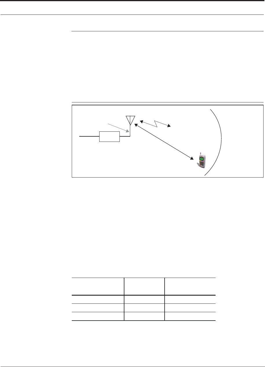
Estimating RF Coverage
6-18 InterReach Fusion Wideband Installation, Operation, and Reference Manual
CONFIDENTIAL D-620616-0-20 Rev G
6.5 Estimating RF Coverage
The maximum output power per carrier (based on the number and type of RF carriers
being transmitted) and the minimum acceptable received power at the wireless device
(that is, the RSSI design goal) essentially establish the RF downlink budget and, con-
sequently, the maximum allowable path loss (APL) between the RAU’s antenna and
the wireless device. Since in-building systems, such as the Fusion Wideband, are gen-
erally downlink-limited, this approach is applicable in the majority of deployments.
Figure 6-1 Determining APL between the Antenna and the Wireless Device
RAU
P = power per Distance = d
G = Antenna Gain
RSSI = power at the
wireless device
carrier from the RAU
Lcoax
= Coaxial cable loss
APL = (P – Lcoax + G) – RSSI (1)
where:
• APL = the maximum allowable path loss in dB
• P = the power per carrier transmitted by the RAU in dBm
•L
coax = the coaxial cable loss between the RAU and passive antenna in dB
• G = the gain of the passive antenna in dBi
Table 6-19 Coaxial Cable Losses (Lcoax)
Length of Cable
(.195 in. diameter) Loss at
850 MHz (dB) Loss at
1900 MHz (dB)
0.9 m (3 ft) 0.6 0.8
1.8 m (6 ft) 1.0 1.5
3.0 m (10 ft) 1.5 2.3
Coaxial cable is used to connect the RAU to an antenna. Table 6-19 lists coaxial cable
loss for various cable lengths.
You can calculate the distance, d, corresponding to the maximum allowable path loss
using equations introduced in the following sections.

Help Hot Line (U.S. only): 1-800-530-9960 6-19
D-620616-0-20 Rev G CONFIDENTIAL
Estimating RF Coverage
6.5.1 Path Loss Equation
In-building path loss obeys the distance power law1 in equation (2):
PL = 20log10(4Sd0f/c) + 10nlog10(d/d0) + &s(2)
where:
• PL is the path loss at a distance, d, from the antenna
• d = the distance expressed in meters
•d
0 = free-space path loss distance in meters
• f = the operating frequency in Hertz.
• c = the speed of light in a vacuum (3.0 × 10⁸ m/sec).
•n = the path loss exponent and depends on the building “clutter” and frequency
of operation
•&s= a normal random variable that depends on partition material and geome-
tries inside the building and is accounted for by the log-normal fade margin
used in the downlink RSSI design goal calculation
As a reference, Table 6-20 provides estimates of signal loss for some RF barriers1.
Table 6-20 Average Signal Loss of Common Building Materials
Partition Type Loss (dB) Frequency (MHz)
Metal wall 26 815
Aluminum siding 20 815
Foil insulation 4 815
Cubicle walls 1.4 900
Concrete block wall 13 1300
Concrete floor 10 1300
Sheetrock 1 to 2 1300
Light machinery 3 1300
General machinery 7 1300
Heavy machinery 11 1300
Equipment racks 7 1300
Assembly line 6 1300
Ceiling duct 5 1300
Metal stairs 5 1300
1. Rappaport, Theodore S. Wireless Communications, Principles, and Practice. Prentice Hall PTR, 1996.

Estimating RF Coverage
6-20 InterReach Fusion Wideband Installation, Operation, and Reference Manual
CONFIDENTIAL D-620616-0-20 Rev G
6.5.2 RAU Coverage Distance
Use equations (1) and (2), on pages 6-18 and 6-19, respectively, to estimate the dis-
tance from the antenna to where the RF signal decreases to the minimum acceptable
level at the wireless device.
With d0 set to one meter and path loss slope (PLS) defined as 10n, Equation (2) can
be simplified to:
PL(d) = 20log10(4Sf/c) + PLS·log10(d) (3)
Table 6-21 gives the value of the first term of Equation (3) (that is., (20log10(4Sf/c))
for various frequency bands.
Table 6-21 Frequency Bands and the Value of the First Term in Equation (3)
Frequency
Band (MHz) Mid-Band
Frequency
(MHz) 20log10(4Sf/c)
Uplink Downlink
800 MHz SMR 806-824 851-869 838 30.9
850 MHz Cellular 824-849 869-894 859 31.1
1800 MHz DCS 1710-1785 1805-1880 1795 37.5
1900 MHz PCS 1850-1910 1930-1990 1920 38.1
2.1 GHz UMTS 1920–1980 2110–2170 2045 38.7
1.7/2.1 GHz AWS 1710-1755 2110-2155 2132.5a
a. Due to the wide frequency spread between the Uplink and Downlink bands, the mid-band frequency
of the Downlink band was chosen for 1.7/2.1 GHz AWS.
39.0
2.5 GHz WiMAX 2496-2690 2496-2690 2595 40.7
Table 6-22 shows estimated PLS for various environments that have different “clut-
ter” (that is, objects that attenuate the RF signals, such as walls, partitions, stairwells,
equipment racks, and so.).
Table 6-22 Estimated Path Loss Slope for Different In-Building Environments
Environment Type Example PLS for
850/900 MHz PLS for 1800/1900/
2100/2500 MHz
Open Environment
very few RF obstructions
Parking Garage, Conven-
tion Center
33.7 30.1
Moderately Open Environment
low-to-medium amount of RF
obstructions
Warehouse, Airport, Man-
ufacturing
35 32
Mildly Dense Environment
medium-to-high amount of RF
obstructions
Retail, Office Space with
approximately 80% cubi-
cles and 20% hard walled
offices
36.1 33.1

Help Hot Line (U.S. only): 1-800-530-9960 6-21
D-620616-0-20 Rev G CONFIDENTIAL
Estimating RF Coverage
By setting the path loss to the maximum allowable level (PL = APL), equation (3) can
be used to estimate the maximum coverage distance of an antenna connected to an
RAU, for a given frequency and type of in-building environment.
d = 10^((APL - 20log10(4Sf/c))/PLS)(4)
For reference, Tables 6-24 through 6-29 show the distance covered by an antenna for
various in-building environments. The following assumptions were made:
• Path loss Equation (4)
• 6 dBm output per carrier at the RAU output
• 3 dBi antenna gain
• RSSI design goal = –85 dBm (typical for narrowband protocols, but not for
spread-spectrum protocols)
Table 6-23 Approximate Radiated Distance from Antenna
for 800 MHz SMR Applications
Environment Type
Distance from Antenna
Meters Feet
Open Environment 75 244
Moderately Open Environment 64 208
Mildly Dense Environment 56 184
Moderately Dense Environment 48 156
Dense Environment 40 131
Moderately Dense Environment
medium-to-high amount of RF
obstructions
Office Space with approx-
imately 50% cubicles and
50% hard walled offices
37.6 34.8
Dense Environment
large amount of RF obstructions
Hospital, Office Space
with approximately 20%
cubicles and 80% hard
walled offices
39.4 38.1
Table 6-22 Estimated Path Loss Slope for Different In-Building Environments
Environment Type Example PLS for
850/900 MHz PLS for 1800/1900/
2100/2500 MHz

Table 6-25 Approximate Radiated Distance from Antenna
for 1800 MHz DCS Applications
Facility
Distance from Antenna
Meters Feet
Open Environment 75 246
Moderately Open Environment 58 191
Mildly Dense Environment 50 166
Moderately Dense Environment 42 137
Dense Environment 30 100
Table 6-26 Approximate Radiated Distance from Antenna
for 1900 MHz PCS Applications
Facility
Distance from Antenna
Meters Feet
Open Environment 72 236
Moderately Open Environment 56 183
Mildly Dense Environment 49 160
Moderately Dense Environment 40 132
Dense Environment 29 96
Estimating RF Coverage
6-22 InterReach Fusion Wideband Installation, Operation, and Reference Manual
CONFIDENTIAL D-620616-0-20 Rev G
Table 6-24 Approximate Radiated Distance from Antenna
for 850 MHz Cellular Applications
Environment Type
Distance from Antenna
Meters Feet
Open Environment 73 241
Moderately Open Environment 63 205
Mildly Dense Environment 55 181
Moderately Dense Environment 47 154
Dense Environment 39 129

Table 6-27 Approximate Radiated Distance from Antenna
for 2.1 GHz UMTS Applications
Facility
Distance from Antenna
Meters Feet
Open Environment 69 226
Moderately Open Environment 54 176
Mildly Dense Environment 47 154
Moderately Dense Environment 39 128
Dense Environment 28 93
Help Hot Line (U.S. only): 1-800-530-9960 6-23
D-620616-0-20 Rev G CONFIDENTIAL
Estimating RF Coverage
Table 6-28 Approximate Radiated Distance from Antenna
for 1.7/2.1 GHz AWS Applications
Facility
Distance from Antenna
Meters Feet
Open Environment 67 220
Moderately Open Environment 52 172
Mildly Dense Environment 46 150
Moderately Dense Environment 38 125
Dense Environment 28 91
Table 6-29 Approximate Radiated Distance from Antenna
for 2.5 GHz WiMAX Applications
Facility
Distance from Antenna
Meters Feet
Open Environment 59 194
Moderately Open Environment 47 152
Mildly Dense Environment 41 134
Moderately Dense Environment 35 112
Dense Environment 25 83

Estimating RF Coverage
6-24 InterReach Fusion Wideband Installation, Operation, and Reference Manual
CONFIDENTIAL D-620616-0-20 Rev G
6.5.3 Examples of Design Estimates
Example Design Estimate for an 1900 MHz CDMA Application
1. Design goals:
• PCS (1920 MHz = average of the lowest uplink and the highest downlink fre-
quency in 1900 MHz PCS band)
• CDMA provider
• 8 CDMA carriers in the system
• –85 dBm design goal (to 95% of the building) — the minimum received power
at the wireless device
• Base station with simplex RF connections
2. Power Per Carrier: The tables in Section 6.3, “Maximum Output Power per Car-
rier,” on page 6-4 provide maximum power per carrier information. The 1900
MHz CDMA table indicates that Fusion Wideband can support eight carriers with
a recommended maximum power per carrier of 6.5 dBm. The input power should
be set to the desired output power minus the system gain.
3. Building information:
• 16 floor building with 9,290 sq. meters (100,000 sq. ft.) per floor; total
148,640 sq. meters (1,600,000 sq. ft.).
• Walls are sheetrock construction, suspended ceiling tiles.
• Antennas used are omni-directional, ceiling mounted.
• Standard office environment, 80% hard wall offices and 20% cubicles.
4. Link Budget: In this example, a design goal of –85 dBm is used. Suppose 3 dBi
omni-directional antennas are used in the design. Then, the maximum RF propa-
gation loss should be no more than 94.5 dB (6.5 dBm + 3 dBi + 85 dBm) over
95% of the area being covered. It is important to note that a design goal such as
–85 dBm is usually derived taking into account multipath fading and log-normal
shadowing characteristics. Thus, this design goal will only be met “on average”
over 95% of the area being covered. At any given point, a fade may bring the sig-
nal level underneath the design goal.
Note that this method of calculating a link budget is only for the downlink path.
For information to calculate link budgets for both the downlink and uplink paths,
refer to Section 6.6 on page 6-26.
5. Path Loss Slope: For a rough estimate, Table 6-22, “Estimated Path Loss Slope for
Different In-Building Environments” on page 6-20, shows that a building with 80%
hard wall offices and 20% cubicles, at 1920 MHz, has an approximate path loss
slope (PLS) of 38.1. Given the RF link budget of 94.5 dB, the distance of coverage
from each RAU will be 30.2 meters (99 ft). This corresponds to a coverage area
of 2,868 sq. meters (30,854 sq. ft.) per RAU (refer to Section 6.5.1 for details on
path loss estimation). For this case we assumed a circular radiation pattern, though
the actual area covered depends upon the pattern of the antenna and the obstructions
in the facility.

Help Hot Line (U.S. only): 1-800-530-9960 6-25
D-620616-0-20 Rev G CONFIDENTIAL
Estimating RF Coverage
6. Equipment Required: Since you know the building size, you can now estimate
the Fusion Wideband equipment quantities needed. Before you test any RF levels
in the building, you can estimate that four antennas per level will be needed. This
assumes no propagation between floors. If there is propagation, you may not need
antennas on every floor.
a. 4 antennas per floor × 16 floors = 64 RAUs
b. 64 RAUs ÷ 8 (maximum 8 RAUs per Expansion Hub) = 8 Expansion Hubs
c. 8 Expansion Hubs ÷ 4 (maximum 4 Expansion Hubs per Main Hub) = 2 Main
Hubs
Check that the fiber and CATV cable distances are as recommended. If the dis-
tances differ, use the tables in Section 6.4, “System Gain,” on page 6-16 to deter-
mine system gains or losses. The path loss may need to be recalculated to assure
adequate signal levels in the required coverage distance.
The above estimates assume that all cable length requirements are met. If Expansion
Hubs cannot be placed so that the RAUs are within the distance requirement, addi-
tional Expansion Hubs may need to be placed closer to the required RAUs locations.
An RF Site Survey and Building Evaluation is required to accurately establish the
Fusion Wideband equipment quantities required for the building. The site survey
measures the RF losses within the building to determine the actual PLS, used in the
final path loss formula to determine the actual requirements of the Fusion Wideband
system.

Link Budget Analysis
6-26 InterReach Fusion Wideband Installation, Operation, and Reference Manual
CONFIDENTIAL D-620616-0-20 Rev G
6.6 Link Budget Analysis
A link budget is a methodical way to account for the gains and losses in an RF system
so that the quality of coverage can be predicted. The end result can often be stated as
a “design goal” in which the coverage is determined by the maximum distance from
each RAU before the signal strength falls beneath that goal.
One key feature of the link budget is the maximum power per carrier explained in
Section 6.3. While the maximum power per carrier is important as far as emissions
and signal quality requirements are concerned, it is critical that the maximum signal
into the Main Hub never exceed 1W (+30 dBm). Composite power levels above this
limit will cause damage to the Main Hub.
WARNING: Exceeding the maximum input power of 1W (+30 dBm)
could cause permanent damage to the Main Hub.
NOTE: Visit the TE customer portal at http://www.te.com/adc for the
on-line Link Budget Tool.
6.6.1 Elements of a Link Budget for Narrowband Standards
The link budget represents a typical calculation that might be used to determine how
much path loss can be afforded in a Fusion Wideband design. This link budget ana-
lyzes both the downlink and uplink paths. For most configurations, the downlink
requires lower path loss and is therefore the limiting factor in the system design. It is
for this reason that a predetermined “design goal” for the downlink is sufficient to
predict coverage distance.
The link budget is organized in a simple manner: the transmitted power is calculated,
the airlink losses due to fading and body loss are summed, and the receiver sensitivity
(minimum level a signal can be received for acceptable call quality) is calculated. The
maximum allowable path loss (in dB) is the difference between the transmitted
power, less the airlink losses, and the receiver sensitivity. From the path loss, the
maximum coverage distance can be estimated using the path loss formula presented
in Section 6.5.1.
Table 6-30 provides link budget considerations for narrowband systems.

Help Hot Line (U.S. only): 1-800-530-9960 6-27
D-620616-0-20 Rev G CONFIDENTIAL
Link Budget Analysis
Table 6-30 Link Budget Considerations for Narrowband Systems
Consideration Description
BTS Transmit Power The power per carrier transmitted from the base station output
Attenuation between
BTS and Fusion
Wideband
This includes all losses: cable, attenuator, splitter/combiner, and so forth.
On the downlink, attenuation must be chosen so that the maximum power per carrier going into the
Main Hub does not exceed the levels given in Section 6.3.
On the uplink, attenuation is chosen to keep the maximum uplink signal and noise level low enough
to prevent base station alarms but small enough not to cause degradation in the system sensitivity.
If the Fusion Wideband noise figure minus the attenuation is at least 10 dB higher than the BTS
noise figure, the system noise figure is approximately that of Fusion Wideband alone. Refer to Sec-
tion 6.8 for ways to independently set the uplink and downlink attenuations between the base station
and Fusion Wideband.
Antenna Gain The radiated output power includes antenna gain. For example, if you use a 3 dBi antenna at the
RAU that is transmitting 0 dBm per carrier, the effective radiated power (relative to an isotropic radi-
ator) is 3 dBm per carrier.
BTS Noise Figure This is the effective noise floor of the base station input (usually base station sensitivity is this effec-
tive noise floor plus a certain C/I ratio).
Fusion Wideband
Noise Figure
This is Fusion Wideband’s uplink noise figure, which varies depending on the number of Expansion
Hubs and RAUs, and the frequency band. Fusion Wideband’s uplink noise figure is specified for a
1-1-8 configuration. Thus, the noise figure for a Fusion Wideband system (or multiple systems
whose uplink ports are power combined) is NF(1-1-8) + 10*log(# of Expansion Hubs). This repre-
sents an upper-bound because the noise figure is lower if any of the Expansion Hub’s RAU ports are
not used.
Thermal Noise This is the noise level in the signal bandwidth (BW).
Thermal noise power = –174 dBm/Hz + 10Log(BW).
Protocol Signal
Bandwidth Thermal
Noise
TDMA 30 kHz –129 dBm
GSM 200 kHz –121 dBm
iDEN 25 kHz –130 dBm
Required C/I ratio For each wireless standard, a certain C/I (carrier to interference) ratio is needed to obtain acceptable
demodulation performance. For narrowband systems, (TDMA, GSM, EDGE, iDEN, AMPS) this
level varies from about 9 dB to 20 dB.
Mobile Transmit
Power
The maximum power the mobile can transmit (power transmitted at highest power level setting).
Multipath Fade
Margin
This margin allows for a certain level of fading due to multipath interference. Inside buildings there
is often one or more fairly strong signals and many weaker signals arriving from reflections and dif-
fraction. Signals arriving from multiple paths add constructively or destructively. This margin
accounts for the possibility of destructive multipath interference. In RF site surveys the effects of
multipath fading are typically not accounted for because such fading is averaged out over power
level samples taken over many locations.

Link Budget Analysis
6-28 InterReach Fusion Wideband Installation, Operation, and Reference Manual
CONFIDENTIAL D-620616-0-20 Rev G
Log-normal Fade
Margin
This margin adds an allowance for RF shadowing due to objects obstructing the direct path between
the mobile equipment and the RAU. In RF site surveys, the effects of shadowing are partially
accounted for since it is characterized by relatively slow changes in power level.
Body Loss This accounts for RF attenuation caused by the user’s head and body.
Minimum Received
Signal Level
This is also referred to as the “design goal”. The link budget says that you can achieve adequate cov-
erage if the signal level is, on average, above this level over 95% of the area covered, for example.
Table 6-30 Link Budget Considerations for Narrowband Systems (continued)
Consideration Description

Help Hot Line (U.S. only): 1-800-530-9960 6-29
D-620616-0-20 Rev G CONFIDENTIAL
Link Budget Analysis
6.6.2 Narrowband Link Budget Analysis for a Microcell Application
Table 6-31 Narrowband Link Budget Analysis: Downlink
Line Downlink
Transmitter
a. BTS transmit power per carrier (dBm) 33
b. Attenuation between BTS and Fusion Wideband (dB) –23
c. Power into Fusion Wideband (dBm) 10
d. Fusion Wideband gain (dB) 0
e. Antenna gain (dBi) 3
f. Radiated power per carrier (dBm) 13
Airlink
g. Multipath fade margin (dB) 6
h. Log-normal fade margin with 9 dB std. deviation, 95% area coverage,
87% edge coverage
10
i. Body loss (dB) 3
j. Airlink losses (not including facility path loss) 19
Receiver
k. Thermal noise (dBm/30 kHz) –129
l. Mobile noise figure (dB) 7
m. Required C/I ratio (dB) 17
n. Minimum received signal (dBm) –105
p. Maximum path loss (dB) +99
• c = a + b
• f = c + d + e
• j = g + h + i
• n = k + l + m
• k: in this example, k represents the thermal noise for a TDMA signal, which
has a bandwidth of 30 kHz
• p = f – j – n

Table 6-32 Narrowband Link Budget Analysis: Uplink
Line Uplink
Receiver
a. BTS noise figure (dB) 4
b. Attenuation between BTS and Fusion Wideband (dB) –10
c. Fusion Wideband gain (dB) 0
d. Fusion Wideband noise figure (dB) 1-4-32 22
e. System noise figure (dB) 22.6
f. Thermal noise (dBm/30 kHz) –129
g. Required C/I ratio (dB) 12
h. Antenna gain (dBi) 3
i. Receive sensitivity (dBm) –97.4
Airlink
j. Multipath fade margin (dB) 6
k. Log-normal fade margin with 9 dB std. deviation, 95% area coverage,
87% edge coverage
10
l. Body loss (dB) 3
m. Airlink losses (not including facility path loss) 19
Transmitter
n. Mobile transmit power (dBm) 28
p. Maximum path loss (dB) 106.4
Link Budget Analysis
6-30 InterReach Fusion Wideband Installation, Operation, and Reference Manual
CONFIDENTIAL D-620616-0-20 Rev G
• e: enter the noise figure and gain of each system component (a, b, c, and d) into
the standard cascaded noise figure formula
Fsys = F1 + + + ....
F2 – 1
G1
F3 – 1
G1G2
where
F = 10
(See Rappaport, Theodore S. Wireless Communications, Principles, and Practice. Prentice Hall PTR, 1996.)
(Noise Figure/10)
G = 10(Gain/10)
• i = f + e + g – h
• m = j + k + l
• p = n – m – i
Therefore, the system is downlink limited but the downlink and uplink are almost
balanced, which is a desirable condition.

Help Hot Line (U.S. only): 1-800-530-9960 6-31
D-620616-0-20 Rev G CONFIDENTIAL
Link Budget Analysis
6.6.3 Elements of a Link Budget for CDMA Standards
A CDMA link budget is slightly more complicated because you must consider the
spread spectrum nature of CDMA. Unlike narrowband standards such as TDMA and
GSM, CDMA signals are spread over a relatively wide frequency band. Upon recep-
tion, the CDMA signal is de-spread. In the de-spreading process the power in the
received signal becomes concentrated into a narrow band, whereas the noise level
remains unchanged. Hence, the signal-to-noise ratio of the de-spread signal is higher
than that of the CDMA signal before de-spreading. This increase is called processing
gain. For IS-95 and J-STD-008, the processing gain is 21 dB or 19 dB depending on
the user data rate (9.6 Kbps for rate set 1 and 14.4 Kbps for rate set 2, respectively).
Because of the processing gain, a CDMA signal (comprising one Walsh code channel
within the composite CDMA signal) can be received at a lower level than that
required for narrowband signals. A reasonable level is –95 dBm, which results in
about –85 dBm composite as shown below.
Table 6-33 Distribution of Power within a CDMA Signal
Channel Walsh Code Number Relative Power Level
Pilot 0 20% –7.0 dB
Sync 32 5% –13.3 dB
Primary Paging 1 19% –7.3 dB
Traffic 8–31, 33–63 9% (per traffic channel) –10.3 dB
An important issue to keep in mind is that the downlink CDMA signal is composed of
many orthogonal channels: pilot, paging, sync, and traffic. The composite power
level is the sum of the powers from the individual channels. Table 6-33 shows an
example.
This table assumes that there are 15 active traffic channels operating with 50% voice
activity (so that the total power adds up to 100%). Notice that the pilot and sync chan-
nels together contribute about 25% of the power. When measuring the power in a
CDMA signal you must be aware that if only the pilot and sync channels are active,
the power level will be about 6 to 7 dB lower than the maximum power level you can
expect when all voice channels are active. The implication is that if only the pilot and
sync channels are active, and the maximum power per carrier table says that you
should not exceed 10 dBm for a CDMA signal, for example, then you should set the
attenuation between the base station and the Main Hub so that the Main Hub receives
3 dBm (assuming 0 dB system gain).
An additional consideration for CDMA systems is that the uplink and downlink paths
should be gain and noise balanced. This is required for proper operation of soft-hand-
off to the outdoor network as well as preventing excess interference that is caused by
mobiles on the indoor system transmitting at power levels that are not coordinated
with the outdoor mobiles. This balance is achieved if the power level transmitted by
the mobiles under close-loop power control is similar to the power level transmitted
under open-loop power control.

Link Budget Analysis
6-32 InterReach Fusion Wideband Installation, Operation, and Reference Manual
CONFIDENTIAL D-620616-0-20 Rev G
The open-loop power control equation is
PTX + PRX = –73 dBm (for Cellular, IS-95)
PTX + PRX = –76 dBm (for PCS, J-STD-008)
where PTX is the mobile’s transmitted power and PRX is the power received by the
mobile.
The power level transmitted under closed-loop power control is adjusted by the base
station to achieve a certain Eb/N0 (explained in Table 6-34 on page 6-32). The differ-
ence between these power levels, 'P, can be estimated by comparing the power radi-
ated from the RAU, Pdownink, to the minimum received signal, Puplink, at the RAU:
'P = Pdownink + Puplink + 73 dBm (for Cellular)
'P = Pdownink + Puplink + 76 dBm (for PCS)
It’s a good idea to keep –12 dB < 'P < 12 dB.
Table 6-34 provides link budget considerations for CDMA systems.
Table 6-34 Additional Link Budget Considerations for CDMA
Consideration Description
Multipath Fade
Margin
The multipath fade margin can be reduced (by at least 3 dB) by using different lengths of optical fiber (this
is called “delay diversity”). The delay over fiber is approximately 5S/km. If the difference in fiber
lengths to Expansion Hubs with overlapping coverage areas produces at least 1 chip (0.8S) delay of one
path relative to the other, then the multipaths’ signals can be resolved and processed independently by the
base station’s rake receiver. A CDMA signal traveling through 163 meters of MMF cable is delayed by
approximately one chip.
Power per car-
rier, downlink
This depends on how many channels are active. For example, the signal is about 7 dB lower if only the
pilot, sync, and paging channels are active compared to a fully-loaded CDMA signal. Furthermore, in the
CDMA forward link, voice channels are turned off when the user is not speaking. On average this is
assumed to be about 50% of the time. So, in the spreadsheet, both the power per Walsh code channel (rep-
resenting how much signal a mobile will receive on the Walsh code that it is de-spreading) and the total
power are used.
The channel power is needed to determine the maximum path loss, and the total power is needed to deter-
mine how hard the Fusion Wideband system is being driven.
The total power for a fully-loaded CDMA signal is given by (approximately):
total power = voice channel power + 13 dB + 10log10 (50%)
= voice channel power + 10 dB
Information Rate This is simply
10log10(9.6 Kbps) = 40 dB for rate set 1
10log10(14.4 Kbps) = 42 dB for rate set 2

Help Hot Line (U.S. only): 1-800-530-9960 6-33
D-620616-0-20 Rev G CONFIDENTIAL
Link Budget Analysis
Other CDMA Issues
• Never combine multiple sectors (more than one CDMA signal at the same fre-
quency) into a Fusion Wideband system. The combined CDMA signals will inter-
fere with each other.
• Try to minimize overlap between in-building coverage areas that utilize different
sectors, as well as in-building coverage and outdoor coverage areas. This is impor-
tant because any area in which more than one dominant pilot signal (at the same
frequency) is measured by the mobile will result in soft-handoff. Soft-handoff
decreases the overall network capacity by allocating multiple channel resources to
a single mobile phone.
Process Gain The process of de-spreading the desired signal boosts that signal relative to the noise and interference.
This gain needs to be included in the link budget. In the following formulas, PG = process gain:
PG = 10log10(1.25 MHz / 9.6 Kbps) = 21 dB rate set 1
PG = 10log10(1.25 MHz / 14.4 Kbps) = 19 dB rate set 2
Note that the process gain can also be expressed as 10log10 (CDMA bandwidth) minus the information
rate.
Eb/No This is the energy-per-bit divided by the received noise and interference. It’s the CDMA equivalent of sig-
nal-to-noise ratio (SNR). This figure depends on the mobile’s receiver and the multipath environment. For
example, the multipath delays inside a building are usually too small for a rake receiver in the mobile (or
base station) to resolve and coherently combine multipath components. However, if artificial delay can be
introduced by, for instance, using different lengths of cable, then the required Eb/No is lower and the mul-
tipath fade margin in the link budget can be reduced in some cases.
If the receiver noise figure is NF (dB), then the receive sensitivity (dBm) is given by:
Psensitivity = NF + Eb/No + thermal noise in a 1.25 MHz band – PG
= NF + Eb/No – 113 (dBm/1.25 MHz) – PG
Noise Rise On the uplink, the noise floor is determined not only by the Fusion Wideband system, but also by the num-
ber of mobiles that are transmitting. This is because when the base station attempts to de-spread a particu-
lar mobile’s signal, all other mobile signals appear to be noise. Because the noise floor rises as more
mobiles try to communicate with a base station, the more mobiles there are, the more power they have to
transmit. Hence, the noise floor rises rapidly:
noise rise = 10log10(1 / (1 – loading))
where loading is the number of users as a percentage of the theoretical maximum number of users.
Typically, a base station is set to limit the loading to 75%. This noise ratio must be included in the link
budget as a worst-case condition for uplink sensitivity. If there are less users than 75% of the maximum,
then the uplink coverage will be better than predicted.
Hand-off Gain CDMA supports soft hand-off, a process by which the mobile communicates simultaneously with more
than one base station or more than one sector of a base station. Soft hand-off provides improved receive
sensitivity because there are two or more receivers or transmitters involved. A line for hand-off gain is
included in the CDMA link budgets worksheet although the gain is set to 0 dB because the in-building
system will probably be designed to limit soft-handoff.
Table 6-34 Additional Link Budget Considerations for CDMA (continued)
Consideration Description

Link Budget Analysis
6-34 InterReach Fusion Wideband Installation, Operation, and Reference Manual
CONFIDENTIAL D-620616-0-20 Rev G
6.6.4 CDMA Link Budget Analysis for a Microcell Application
Table 6-35 CDMA Link Budget Analysis: Downlink
Line Downlink
Transmitter
a. BTS transmit power per traffic channel (dBm) 30.0
b. Voice activity factor 50%
c. Composite power (dBm) 40.0
d. Attenuation between BTS and Fusion Wideband (dB) –24
e. Power per channel into Fusion Wideband (dBm) 9.0
f. Composite power into Fusion Wideband (dBm) 16.0
g. Fusion Wideband gain (dB) 0.0
h. Antenna gain (dBi) 3.0
i. Radiated power per channel (dBm) 12.0
j. Composite radiated power (dBm) 19.0
Airlink
k. Handoff gain (dB) 0.0
l. Multipath fade margin (dB) 6.0
m. Log-normal fade margin with 9 dB std. deviation, 95% area cover-
age, 87% edge coverage
10.0
n. Additional loss (dB) 0.0
o. Body loss (dB) 3.0
p. Airlink losses (not including facility path loss) 19.0
Receiver
q. Mobile noise figure (dB) 7.0
r. Thermal noise (dBm/Hz) –174.0
s. Receiver interference density (dBm/Hz) –167.0
t. Information ratio (dB/Hz) 41.6
u. Required Eb/(No+lo) 7.0
v. Minimum received signal (dBm) –118.4
w. Maximum path loss (dB) +99.4

Help Hot Line (U.S. only): 1-800-530-9960 6-35
D-620616-0-20 Rev G CONFIDENTIAL
Link Budget Analysis
• b and c: see notes in Table 6-34 regarding power per carrier, downlink
• e = a + d
• f = c + d
• i = e + g + h
• j = f + g + h
• p = –k + l + m + n + o
• s = q + r
• v = s + t + u
• w = j – p – v
• x = j (downlink) + m (uplink) + P
where
P = Ptx + Prx = –73 dB for Cellular
–76 dB for PCS

Table 6-36 CDMA Link Budget Analysis: Uplink
Line Uplink
Receiver
a. BTS noise figure (dB) 3.0
b. Attenuation between BTS and Fusion Wideband (dB) –30.0
c. Fusion Wideband gain (dB) 0.0
d. Fusion Wideband noise figure (dB) 22.0
e. System noise figure (dB) 33.3
f. Thermal noise (dBm/Hz) –174.0
g. Noise rise 75% loading (dB) 6.0
h. Receiver interference density (dBm/Hz) –134.6
i. Information rate (dB/Hz) 41.6
j. Required Eb/(No+lo) 5.0
k. Handoff gain (dB) 0.0
l. Antenna gain (dBi) 3.0
m. Minimum received signal (dBm) –91.1
Airlink
n. Multipath fade margin (dB) 6.0
o. Log-normal fade margin with 9 dB std. deviation, 95% area cover-
age, 87% edge coverage
10.0
p. Additional loss (dB) 0.0
q. Body loss (dB) 3.0
r. Airlink losses (not including facility path loss) 19.0
Transmitter
s. Mobile transmit power (dBm) 28.0
t. Maximum path loss (dB) 100.1
Link Budget Analysis
6-36 InterReach Fusion Wideband Installation, Operation, and Reference Manual
CONFIDENTIAL D-620616-0-20 Rev G

Help Hot Line (U.S. only): 1-800-530-9960 6-37
D-620616-0-20 Rev G CONFIDENTIAL
Link Budget Analysis
• e: enter the noise figure and gain of each system component (a, b, c, and d) into
the standard cascaded noise figure formula
Fsys = F1 + + + ....
F2 – 1
G1
F3 – 1
G1G2
where
F = 10
(See Rappaport, Theodore S. Wireless Communications, Principles, and Practice. Prentice Hall PTR, 1996.)
(Noise Figure/10)
G = 10(Gain/10)
• h = e + f + g
• m = h + i + j –k – l
• r = n + o + p + q
• t = s – r – m
6.6.5 Considerations for Re-Radiation (Over-the-Air) Systems
Fusion Wideband can be used to extend the coverage of the outdoor network by con-
necting to a roof-top donor antenna pointed toward an outdoor base station. Addi-
tional considerations for such an application of Fusion Wideband are:
• Sizing the gain and output power requirements for a bi-directional amplifier
(repeater).
• Ensuring that noise radiated on the uplink from the in-building system does not
cause the outdoor base station to become desensitized to wireless handsets in the
outdoor network.
• Filtering out signals that lie in adjacent frequency bands. For instance, if you are
providing coverage for Cellular B-band operation it may be necessary to filter out
the A, A’ and A” bands which may contain strong signals from other outdoor base
stations.
Further information on these issues can be found in TE application notes for re-radia-
tion applications.

Optical Power Budget
6-38 InterReach Fusion Wideband Installation, Operation, and Reference Manual
CONFIDENTIAL D-620616-0-20 Rev G
6.7 Optical Power Budget
Fusion Wideband uses SC/APC connectors. The connector losses associated with
mating to these connectors is accounted for in the design and should not be included
as elements of the optical power budget. The reason is that when the optical power
budget is defined, measurements are taken with these connectors in place.
The Fusion Wideband optical power budget for both multi-mode and sin-
gle-mode fiber cable is 3.0 dB (optical).
The maximum loss through the fiber can not exceed 3 dB (optical). The maximum
lengths of the fiber cable should not exceed 500m (1,640 ft) for multi-mode and 6 km
(19,685 ft) for single-mode. Both the optical budget and the maximum cable length
must be taken into consideration when designing the system.
NOTE: It is critical to system performance that only SC/APC fiber connectors are
used throughout the fiber network, including fiber distribution panels.

Help Hot Line (U.S. only): 1-800-530-9960 6-39
D-620616-0-20 Rev G CONFIDENTIAL
Connecting a Main Hub to a Base Station
6.8 Connecting a Main Hub to a Base Station
The Fusion Wideband system supports up to three RF sources: one for Band 1, one
for Band 2 and one for Band 3. This section explains how each band can be connected
to its associated base station.
Each Fusion Main Hub band has separate system gain parameters. For example, Band
1 can be set for +5 dB of downlink system gain while Band 2 can have +15 dB of
downlink system gain. Thus, each band can be configured as a separate system to
allow for full integration to its associated base station.
When connecting each of the Fusion Wideband Main Hub bands to its base station,
the following equipment may be required: circulators, filter diplexers, directional
couplers, combiner/splitters, attenuators, coax cables, and connectors. In addition, use
the following considerations to achieve optimal performance:
1. The downlink power from the base stations must be attenuated enough so that the
power radiated by the RAU does not exceed the maximum power per carrier listed
in Section 6.3, “Maximum Output Power per Carrier,” on page 6-4.
2. The uplink attenuation should be small enough that the sensitivity of the overall
system is limited by Fusion Wideband, not by the attenuator. However, some base
stations trigger alarms if the noise or signal levels are too high. In this case the
attenuation must be large enough to prevent this from happening.
CAUTION:The UPLINK and DOWNLINK ports cannot handle a DC power
feed from a BTS. If DC power is present, a DC block must be used or the
Fusion Wideband Main Hub may be damaged.
If, in an area covered by Fusion Wideband, a mobile phone indicates good signal
strength but consistently has difficulty completing calls, it is possible that the attenua-
tion between Fusion Wideband and the base station needs to be adjusted. In other
words, it is possible that if the uplink is over-attenuated, the downlink power will pro-
vide good coverage, but the uplink coverage distance will be small.
When there is an excessive amount of loss between the Fusion Wideband Main Hub
uplink and its associated band’s base station, the uplink system gain can be increased
to as much as 15 dB to prevent a reduction in the overall system sensitivity.
6.8.1 Uplink Attenuation
The attenuation between the Main Hub’s uplink port and the associated band’s base
station reduces both the noise level and the desired signals out of Fusion Wideband.
Setting the attenuation on the uplink is a trade-off between keeping the noise and
maximum signal levels transmitted from Fusion Wideband to the base station
receiver low while not reducing the SNR (signal-to-noise ratio) of the path from the

Connecting a Main Hub to a Base Station
6-40 InterReach Fusion Wideband Installation, Operation, and Reference Manual
CONFIDENTIAL D-620616-0-20 Rev G
RAU inputs to the base station inputs. This SNR can not be better than the SNR of
Fusion Wideband by itself, although it can be significantly worse.
A good rule of thumb is to set the uplink attenuation such that the noise level out of
Fusion Wideband is within 10 dB of the base station’s sensitivity.
6.8.2 RAU Attenuation and ALC
The RAU attenuation and ALC are set using the AdminBrowser Edit Unit Proper-
ties screen.
Embedded within the uplink RF front-end of each Fusion Wideband RAU band is an
ALC circuit. This ALC circuit protects the Fusion Wideband system from overload
and excessive intermodulation products due to high-powered mobiles or other signal
sources that are within the supported frequency band and are in close proximity to the
RAU.
Each individual Band (1or 2) of a Fusion Wideband RAU has an uplink ALC circuit
that operates as a feedback loop. A power detector measures the level of each band’s
uplink RF input and if that level exceeds –30 dBm, an RF attenuator is activated. The
level of attenuation is equal to the amount that the input exceeds –30 dBm. The fol-
lowing sequence describes the operation of the ALC circuit, as illustrated in
Figure 6-2.
1. The RF signal level into either Band of the RAU rises above the activation thresh-
old (–30 dBm), causing that ALC loop to enter into the attack phase.
2. During the attack phase, the ALC loop increases the attenuation (0 to 30 dB) until
the detector reading is reduced to the activation threshold. The duration of this
attack phase is called the attack time.
3. After the attack time, the ALC loop enters the hold phase and maintains a fixed
attenuation so long as the high-level RF signal is present.
4. The RF signal level drops below the release threshold (–45 dBm) and the ALC
loop enters the release phase.
5. During the release phase, the ALC loop holds the attenuation for a fixed period
then quickly releases the attenuation.
An important feature of the ALC loop is that in Step 3, the attenuation is maintained
at a fixed level until the signal drops by a significant amount. This prevents the ALC
loop from tracking variations in the RF signal itself and distorting the waveform
modulation.
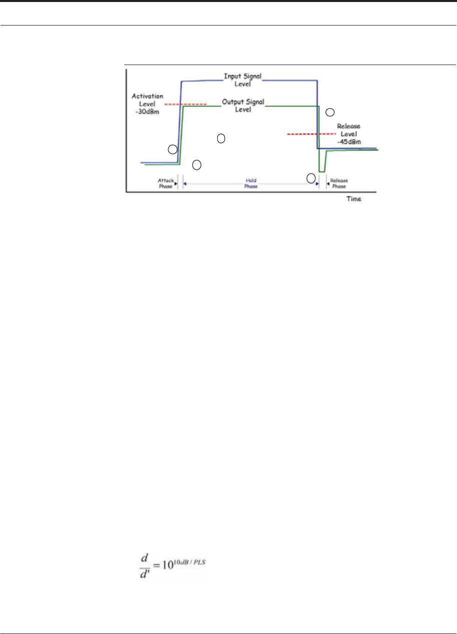
Help Hot Line (U.S. only): 1-800-530-9960 6-41
D-620616-0-20 Rev G CONFIDENTIAL
Connecting a Main Hub to a Base Station
Figure 6-2 ALC Operation
1
2
3
4
5
6.8.2.1 Using the RAU 10 dB Attenuation Setting
Each RAU band can, independently of the other RAUs in a system, have its uplink or
downlink gain attenuated by 0 or 10 dB for each RAU band (1, 2 or 3). This is accom-
plished by selecting the appropriate UPLINK and/or DOWNLINK attenuation for
each RAU band in the Edit Unit Properties screen of AdminBrowser for the selected
RAU.
•Downlink Attenuation: The downlink attenuator provides a mechanism to reduce
the signal strength from an RAU band. For instance, this could be for an RAU
band located near a window in a tall building that is causing excessive leakage to
the macro-network. In such a case it is important to attenuate the downlink only.
The uplink should not be attenuated. If the uplink is attenuated, the uplink sensitiv-
ity is reduced and mobile phones in the area of that RAU band will have to trans-
mit at a higher power. This would increase interference to the outdoor network
from such mobiles.
•Uplink Attenuation: The uplink attenuator attenuates environmental noise picked
up by an RAU band located in an area where heavy electrical machinery is operat-
ing. In such environments the electrical noise can be quite high and it is useful to
reduce the amount of such noise that gets propagated through the distributed
antenna system. Attenuating the uplink of an RAU band located in areas of high
electrical noise helps preserve the sensitivity of the rest of the system.
The effect of activating the uplink or downlink attenuators is to reduce the coverage
area of the adjusted RAU band. The coverage radius will be reduced by roughly a fac-
tor of 2. More specifically, if d is the coverage distance without attenuation and d’ is
the coverage radius with the attenuation, then
where PLS is path loss slope (dBm).

Connecting a Main Hub to a Base Station
6-42 InterReach Fusion Wideband Installation, Operation, and Reference Manual
CONFIDENTIAL D-620616-0-20 Rev G
6.8.2.2 Using the Uplink ALC Setting
Uplink automatic level control (UL ALC) circuitry for each band within the RAU
provides automatic level control on high-power signals in the uplink path. This func-
tionality is required to prevent RF signal compression caused by a single or multiple
wireless devices in very close proximity to the RAU band. Compression causes signal
degradation and, ultimately, dropped calls and data errors, and should be prevented.
Two settings are available to optimize UL ALC performance:
•Multiple Operators: Use when more than one operator and/or protocol is present
in the Fusion Wideband system’s band frequency or adjacent frequency bands.
This setting is most commonly used.
•Single Operator and Protocol: Use when only one operator and protocol is
on-the-air within the Fusion Wideband system’s configured and adjacent fre-
quency bands. This setting is seldom used.

InterReach Fusion Wideband Installation, Operation, and Reference Manual 7-1
D-620616-0-20 Rev G CONFIDENTIAL
SECTION 7 Installing Fusion Wideband
This section contains the following subsections:
• Section 7.1 Installation Requirements 7-1
• Section 7.2 Safety Precautions . . . . . . . . . . . . . . . . . . . . . . . . . . . . . . . . . . . . 7-3
• Section 7.3 Preparing for System Installation . . . . . . . . . . . . . . . . . . . . . . . . . 7-6
• Section 7.4 Fusion Wideband Installation Procedures . . . . . . . . . . . . . . . . . 7-10
• Section 7.5 Splicing Fiber Optic Cable . . . . . . . . . . . . . . . . . . . . . . . . . . . . . 7-45
• Section 7.6 Interfacing the Fusion Wideband Main Hub to an RF Source . . 7-47
• Section 7.7 Connecting Contact Alarms to a Fusion Wideband System . . . . 7-58
• Section 7.8 Alarm Monitoring Connectivity Options . . . . . . . . . . . . . . . . . . 7-66
7.1 Installation Requirements
Before and during installation, keep in mind these sources of potential problems:
• Faulty cabling/connector
• Dirty connectors and ports
• Malfunction of one or more Fusion Wideband components
• Antenna, base station, or repeater problem
• External RF interface
• Tripped circuit breaker
• Equipment is not grounded
• Using a crossover Ethernet cable that does not support full hardware handshaking
when using AdminBrowser

Installation Requirements
7-2 InterReach Fusion Wideband Installation, Operation, and Reference Manual
CONFIDENTIAL D-620616-0-20 Rev G
NOTE: Faulty cabling is the cause of a vast majority of problems. All CATV cable
should be tested to TIA-570-B specifications.
7.1.1 Component Location Requirements
Fusion Wideband components are intended to be installed in indoor locations only.
If outdoor installation is desired, such as a parking garage, the Fusion Wideband com-
ponents must be installed in the appropriate environmental enclosures.
7.1.2 Cable and Connector Requirements
Fusion Wideband equipment operates over the following:
• CATV 75 Ohm cable with F connectors
• Single-mode fiber (SMF) or multi-mode (MMF) cable with SC/APC fiber connec-
tors throughout the fiber network, including fiber distribution panels
These cables are widely-used, industry standards for the cable TV industry. The regu-
lations and guidelines for Fusion Wideband cable installation are identical to those
specified by the TIA/EIA 568-B standard and the TIA/EIA/570-A standards.
TE recommends solid copper center conductor, plenum-rated CATV cable and con-
nectors for conformity to building codes, standards, and to ensure stated performance
of maximum distance and RF specifications.
CommScope 2065V cable or equivalent is required for RG-59.
CommScope 2279V cable or equivalent is required for RG-6.
CommScope 2293K cable may also be used for RG-11.
NOTE: Refer to Appendix A for more information related to 75 Ohm
CATV.
TE recommends connectors with fixed centerpins to ensure proper seating and to
eliminate oxidation, which occurs with bare center conductors. Recommended con-
nectors are as follows:
CANARE Connectors
• FP-C4F for CommScope 2065V cable
• FP-C55A for CommScope 2279V cable
• FP-C71A for CommScope 2293K cable

Help Hot Line (U.S. only): 1-800-530-9960 7-3
D-620616-0-20 Rev G CONFIDENTIAL
Safety Precautions
NOTE: The proper crimp tool and die must be matched by the connector
type.
7.1.3 Distance Requirements
Table 7-1 shows the distances between Fusion Wideband components and related
equipment.
Table 7-1 Distance Requirements
Equipment
Combination Cable Type Cable Length Additional Information
Repeater/BTS to
Fusion Wideband
Main Hub
Coaxial; N male
connectors
3–6 m (10–20 ft) typical Limited by loss and noise.
Refer to your link budget
calculation.
10 m (33 ft) maximum Limited by CE Mark require-
ments.
Fusion Wideband
Expansion Hub to
RAU
CATV 75 Ohm;
shielded F male con-
nectors
• Minimum: 10 meters (33 ft)
• Maximum:
130 meters (426 ft) for RG-59;
140 meters (459 ft) for RG-6;
235 meters (771 ft) for RG-11
Refer to Table 5-1 and Table 5-2.
Refer to “System Gain” on
page 6-16.
Main Hub to Expan-
sion Hub
Multi-mode fiber:
Single-mode fiber:
SC/APC male con-
nectors
500 m (1640 ft.) maximum
6 km (19,685 ft.) maximum
Limited by 3 dB optical
attenuation
RAU to passive
antenna
Coaxial; N male
connectors
1–3.5 m (3–12 ft) typical Limited by loss and noise.
Refer to your link budget
calculation.
7.2 Safety Precautions
7.2.1 Installation Guidelines
Use the following guidelines when installing TE equipment:
1. Provide sufficient airflow and cooling to the equipment to prevent heat build-up
from exceeding the maximum ambient air temperature specification. Do not com-
promise the amount of airflow required for safe operation of the equipment.
2. If you are removing the system, turn it off and remove the power cord first. There
are no user-serviceable parts inside the components.

Safety Precautions
7-4 InterReach Fusion Wideband Installation, Operation, and Reference Manual
CONFIDENTIAL D-620616-0-20 Rev G
3. The internal power supplies have internal fuses that are not user replaceable. Con-
sider the worst-case power consumption shown on the product labels when provi-
sioning the equipment’s AC power source and distribution.
4. Verify that the Hub is grounded properly using the AC power cord third wire
ground.
NOTE: Be careful with the mechanical loading of the rack mounted hub.
Mount the equipment in the rack in such a way that a hazardous condition,
due to uneven mechanical loading, does not result.
7.2.2 General Safety Precautions
The following precautions apply to TE products:
• The units have no user-serviceable parts. Faulty or failed units are fully replaceable
through TE. Please contact us at:
1-800-530-9960 (U.S. and Canada only)
+1-952-917-0761 (International)
• When you connect the fiber optic cable, clean all optical fiber SC/APC connectors
according to the cable manufacturer’s instructions.
• When you connect a radiating antenna to an RAU, firmly hand-tighten the N con-
nector – DO NOT over-tighten the connector.
WARNING: To reduce the risk of fire or electric shock, do not
expose this equipment to rain or moisture. The components are
intended for indoor use only. Do not install the RAU outdoors. Do not
connect an RAU to an antenna that is located outdoors where it could
be subject to lightning strikes, power crosses, or wind.
• The Expansion Hub and RAU units are designed for intra-building cabling only.
Outdoor routing of any cabling to these units shall not exceed 140 feet.
NOTE: Outdoor cables farther than 140 feet must be installed with proper
lightning protection.
7.2.3 Fiber Port Safety Precautions
The following are suggested safety precautions for working with fiber ports. For
information about system compliance with safety standards, refer to Appendix B.

Help Hot Line (U.S. only): 1-800-530-9960 7-5
D-620616-0-20 Rev G CONFIDENTIAL
Safety Precautions
WARNING: Observe the following warning about viewing fiber
ends in ports. Do not stare with unprotected eyes at the connector
ends of the fibers or the ports of the hubs. Invisible infrared radia-
tion is present at the front panel of the Main Hub and the Expansion
Hub. Do not remove the fiber port dust caps unless the port is going
to be used. Do not stare directly into a fiber port.
•Test fiber cables: When you test fiber optic cables, connect the optical power
source last and disconnect it first. Use Class 1 test equipment.
•Fiber ends: Cover any unconnected fiber ends with an approved cap. Do not use
tape.
•Broken fiber cables: Do not stare with unprotected eyes at any broken ends of the
fibers. Laser light emitted from fiber sources can cause eye injury. Avoid contact
with broken fibers; they are sharp and can pierce the skin. Report any broken fiber
cables and have them replaced.
•Cleaning: Be sure the connectors are clean and free of dust or oils. Use only
approved methods for cleaning optical fiber connectors.
•Modifications: Do not make any unauthorized modifications to this fiber optic
system or associated equipment.
•Live work: Live work is permitted because TE equipment is a Class 1 hazard.
•Signs: No warning signs are required.
•Class 1 laser product: The system meets the criteria for a Class 1 laser product
per IEC 60825-1: 1993+A1:+A2:2001 and IEC106825-2.
This mark appears on the front panel of the
Main Hub and the Expansion Hub.
CLASS 1
LASER PRODUCT
CLASS 1
LASER PRODUCT
Complies with 21 CFR 1040.10 and 1040.11 except for deviations pursuant to
Laser Notice No. 50, dated July 26, 2001.
The hazard level at all locations within the equipment is Hazard Level 1.
•CAUTION: Use of controls or adjustments or performance of procedures other
than those specified herein may result in hazardous radiation exposure.

Preparing for System Installation
7-6 InterReach Fusion Wideband Installation, Operation, and Reference Manual
CONFIDENTIAL D-620616-0-20 Rev G
7.3 Preparing for System Installation
7.3.1 Pre-Installation Inspection
Follow this procedure before installing Fusion Wideband equipment:
1. Verify the number of packages received against the packing list.
2. Check all packages for external damage; report any external damage to the ship-
ping carrier. If there is damage, a shipping agent should be present before you
unpack and inspect the contents because damage caused during transit is the
responsibility of the shipping agent.
3. Open and check each package against the packing list. If any items are missing,
contact TE customer service (refer to Section 7.2.2 on page 7-4).
4. If damage is discovered at the time of installation, contact the shipping agent.
7.3.2 Installation Checklist
Table 7-2 Installation Checklist
3Installation Requirement Consideration
Floor Plans Installation location of equipment clearly marked
System Design Used to verify frequency bands after installation
Power available:
Fusion Wideband Main Hub (AC)
Fusion Wideband Expansion Hub (AC)
To RAU (DC)
Fusion Wideband Main Hub (DC)
Fusion Wideband Expansion Hub (DC)
Hub’s power cord is 2 m (6.5 ft) long.
100/240V, 1A, 50–60 Hz
100/240V, 6A, 50-60 Hz
54V (from the Hub)
38–64VDC, 2.5A
38–64VDC, 14A
Rack space available
(Main and Expansion Hub)
89 mm (3.5 in.) high (2U)
Wallmount Fusion Wideband Main Hub Hub must be mounted on 3/4” plywood backboard.
Clearance for air circulation:
Fusion Wideband Main or Expansion Hub
RAU
76 mm (3 in.) front and rear, 51 mm (2 in.) sides
76 mm (3 in.) all around
Suitable operating environment:
Fusion Wideband Main or Expansion Hub
RAUs
Indoor location only
0° to +45°C (+32° to +113°F)
5% to 95% non-condensing humidity
–25° to +45°C (–13° to +113°F)
5% to 95% non-condensing humidity
Donor Antenna-to-Fusion Wideband Configuration (for each Fusion Wideband Band)
Donor Antenna Installed, inspected; N-male to N-male coaxial cable to lightning arrestor/surge
suppressor
Lightning Arrestor or
Surge Suppressor
Installed between roof-top antenna and repeater; N-male to N-male 50 Ohm coax-
ial cable and outdoor cables longer than 140 feet.

Help Hot Line (U.S. only): 1-800-530-9960 7-7
D-620616-0-20 Rev G CONFIDENTIAL
Preparing for System Installation
Repeater Installed between lightning arrestor/surge suppressor and Hub; N-male to N-male
coaxial cable. The Repeater must be a UL listed product.
Attenuator Installed between the circulator and the Hub downlink port to prevent overload.
Optionally, it may be installed between the uplink port and the circulator.
Circulator or Duplexer Installed between the repeater and the Hub uplink and downlink ports
Base Station-to-Fusion Wideband Configuration (for each Fusion Wideband Band)
Base Station Installed, inspected; verify RF power (see tables in Section 6.3 on page 6-4);
N-male to N-male coaxial cable
Attenuator Attenuation may be required to achieve the desired RF output at the RAU, and the
desired uplink noise floor level
Circulator or Duplexer When using a duplex BTS: Installed between the BTS and the Hub uplink and
downlink ports. Not used with a simplex BTS
Connecting Multiple Fusion Wideband Main Hubs Together
5-port Alarm Daisy-Chain Cable
(PN 4024-3)
For contact alarm monitoring of fault and warning alarms. Used to feed the alarms
from multiple Fusion Wideband Main Hubs into a BTS or FlexWave Focus. N.C.
Operation.
Cabling
Coaxial: repeater, base station, Smart Source
to Fusion Wideband Main Hub
Coax approved; N-type male connectors.
Coaxial: RAU to passive
antennas
Use low-loss cable; N male connector; typical 1 m (3.3 ft) using RG142 coaxial
cable.
Fiber: Main Hub to Expansion Hubs SC/APC (angle-polished) male connectors for entire fiber run (can use SC/APC
pigtails, PN 4012SCAPC-10 for MMF or 4013SCAPC-10 for SMF);
Use jumper fiber cables for collocated Main and Expansion Hubs (3 m/10 ft.):
Multi-mode: PN 4017SCAPC-10
Single-mode: PN 4018SCAPC-10
Distance limited by optical loss of 3 dB
Multi-mode up to 500 m (1640 ft.)
Single-mode up to 6 km (19,685 ft.)
CATV TIA-570-B approved; centerpin F male connectors. CATV connectors must be
connected to the shield at both ends. The RAU will be damaged if it is mis-wired.
Tie-off cables to avoid damaging the connectors because of cable strain.
Fusion Wideband Expansion Hub to RAUs • Minimum: 0 meters (0 ft)
• Maximum: RG-59: 130 meters (426 ft) *
RG-6: 140 meters (459 ft)
RG-11: 235 meters (771 ft)
Table 7-2 Installation Checklist (continued)
3Installation Requirement Consideration

Preparing for System Installation
7-8 InterReach Fusion Wideband Installation, Operation, and Reference Manual
CONFIDENTIAL D-620616-0-20 Rev G
7.3.3 Tools and Materials Required
Table 7-3 Tools and Materials Required for Component Installation
3Description
Cable ties
Screwdriver
Mounting screws and spring nuts
Screws, anchors (for mounting RAUs)
Drill
Fiber connector cleaning kit
Fusion splicer
Splicing tool kit (including snips, cladding strippers, fiber cleaver, isopropyl alcohol,
lint-free wipes)
Fusion splicing sleeves
* Refer to Appendix A for CATV cable requirements.
Configuring the System
PC/laptop running
standard browser software
Refer to the AdminBrowser User Manual (PN D-620607-0-20)
Miscellaneous
Cross-over Ethernet cable Male connectors; Fusion Wideband Main Hub to a PC/laptop running a standard
browser to the Fusion Wideband AdminBrowser software; local connection or
LAN switch connector for remote connections.
Straight-through cable Female/male connectors; Fusion Wideband Main Hub to a modem for a remote
connection.
Distances
Fusion Wideband Main Hub is within 3–6m
(10–20 ft) of connecting repeater/BTS/Flex-
Wave
If longer distance, determine the loss of the cable used for this connection and
adjust the RF signal for each Band into the Fusion Wideband Main Hub accord-
ingly. This can be done by readjusting the power from the base station, or by
changing the attenuation value between the base station/repeater and the Hub
Bands (1 and 2).
Table 7-2 Installation Checklist (continued)
3Installation Requirement Consideration

Help Hot Line (U.S. only): 1-800-530-9960 7-9
D-620616-0-20 Rev G CONFIDENTIAL
Preparing for System Installation
7.3.4 Optional Accessories
Table 7-4 Optional Accessories for Component Installation
3Description
Wall-mount bracket (PN 4712)
When using this bracket with an Fusion Wideband Main Hub, the Hub’s mounting
bracket must be moved to the alternate mounting position (refer to the procedure on
page page 7-11).
Cable management (Cable manager: PN 4759; Tie wrap bar: PN 4757)
Splice trays
Pigtails with SC/APC connectors, 3 m (10 ft.)
Multi-mode fiber SC/APC pigtail: PN 4012SCAPC-10
Single-mode fiber SC/APC pigtail: PN 4013SCAPC-10
Jumper cable when Main and Expansion Hubs are collocated, 3 m (10 ft.)
Multi-mode fiber SC/APC: PN 4018SCAPC-10
Line Sharing Switch:
When using a single POTS line with multiple Fusion Wideband Main Hubs, connect
up to four or eight modems to a line sharing switch:
4-port (240031-0)
8-port (240052-0)
Alarm Cables:
5-port Alarm Daisy-Chain Cable (PN 4024-3)
Alarm Sense Adapter Cable (PN 4025-1)

Fusion Wideband Installation Procedures
7-10 InterReach Fusion Wideband Installation, Operation, and Reference Manual
CONFIDENTIAL D-620616-0-20 Rev G
7.4 Fusion Wideband Installation Procedures
The following procedures assume that the system is new from the factory and that it
has not been programmed with bands.
If you are replacing components in a pre-installed system with either new units or
units that may already be programmed (for example, re-using units from another sys-
tem), refer to Section 8.
• Installing a Fusion Wideband Main Hub . . . . . . . . . . . . . . . . . . . . . . . . . . . . . 7-11
• Installing a Fusion Wideband Main Hub in a Rack . . . . . . . . . . . . . . . . . . 7-11
• Using the Wall Rack-Mounting Option . . . . . . . . . . . . . . . . . . . . . . . . . . . 7-13
• Installing an Optional Cable Manager in the Rack . . . . . . . . . . . . . . . . . . 7-12
• Installing a Main Hub Using the 12” Wall-Mounted Rack (PN 4712) . . . . 7-12
• Installing a Fusion Wideband Main Hub Directly to the Wall . . . . . . . . . . 7-14
• Connecting the Fiber Cables to the Main Hub . . . . . . . . . . . . . . . . . . . . . . 7-15
• Making Power Connections . . . . . . . . . . . . . . . . . . . . . . . . . . . . . . . . . . . . 7-18
• Powering On the Main Hub . . . . . . . . . . . . . . . . . . . . . . . . . . . . . . . . . . . . 7-24
• Installing Expansion Hubs . . . . . . . . . . . . . . . . . . . . . . . . . . . . . . . . . . . . . . . . 7-26
• Installing an Expansion Hub in a Rack . . . . . . . . . . . . . . . . . . . . . . . . . . . 7-26
• Installing an Expansion Hub Using the 12” Wall-Mounted Rack . . . . . . . 7-27
• Installing a Fusion Wideband Expansion Hub Directly to the Wall . . . . . . 7-28
• Installing an Optional Cable Manager in the Rack . . . . . . . . . . . . . . . . . . 7-29
• Powering On the Expansion Hub . . . . . . . . . . . . . . . . . . . . . . . . . . . . . . . . 7-29
• Connecting the Fiber Cables to the Expansion Hub . . . . . . . . . . . . . . . . . . 7-30
• Connecting the 75 Ohm CATV Cables . . . . . . . . . . . . . . . . . . . . . . . . . . . 7-31
• Troubleshooting Expansion Hub LEDs During Installation . . . . . . . . . . . 7-32
• Installing RAUs . . . . . . . . . . . . . . . . . . . . . . . . . . . . . . . . . . . . . . . . . . . . . . . . 7-33
• Installing RAUs . . . . . . . . . . . . . . . . . . . . . . . . . . . . . . . . . . . . . . . . . . . . . 7-33
• Installing Passive Antennas . . . . . . . . . . . . . . . . . . . . . . . . . . . . . . . . . . . . 7-33
• Connecting the Antenna to the RAU . . . . . . . . . . . . . . . . . . . . . . . . . . . . . 7-35
• Connecting the CATV Cable . . . . . . . . . . . . . . . . . . . . . . . . . . . . . . . . . . . 7-35
• Troubleshooting Using RAU LEDs During Installation . . . . . . . . . . . . . . 7-36
• Configuring the Fusion Wideband System . . . . . . . . . . . . . . . . . . . . . . . . . . . . 7-37
• Connecting a PC to the Main Hub to Run AdminBrowser . . . . . . . . . . . . 7-37
• Programming the Main Hub Using AdminBrowser . . . . . . . . . . . . . . . . . . 7-38
• Fusion Splicing of Fiber and Pigtail . . . . . . . . . . . . . . . . . . . . . . . . . . . . . . . . . 7-45
Help Hot Line (U.S. only): 1-800-530-9960 7-11
D-620616-0-20 Rev G CONFIDENTIAL
Fusion Wideband Installation Procedures
The following procedures assume that the system is installed and programmed.
• Interfacing the Fusion Wideband Main Hub to an RF Source . . . . . . . . . . . . . 7-47
• Connecting a Single Fusion Wideband Main Hub to an RF Source . . . . . 7-47
• Connecting a Fusion Wideband Main Hub to a Roof-top Antenna . . . . . . 7-51
• Connecting Multiple Fusion Wideband Main Hubs to an RF Source . . . . 7-52
• Connecting Multiple Wideband Main Hubs to a Duplex Repeater or BTS 7-55
• Connecting Contact Alarms to a Fusion Wideband System . . . . . . . . . . . . . . . 7-58
• Alarm Source . . . . . . . . . . . . . . . . . . . . . . . . . . . . . . . . . . . . . . . . . . . . . . . 7-59
• Alarm Sense . . . . . . . . . . . . . . . . . . . . . . . . . . . . . . . . . . . . . . . . . . . . . . . . 7-62
• Alarm Cables . . . . . . . . . . . . . . . . . . . . . . . . . . . . . . . . . . . . . . . . . . . . . . . 7-64
• Alarm Monitoring Connectivity Options . . . . . . . . . . . . . . . . . . . . . . . . . . . . . 7-66
• Direct Connection . . . . . . . . . . . . . . . . . . . . . . . . . . . . . . . . . . . . . . . . . . . . 7-66
• Modem Connection . . . . . . . . . . . . . . . . . . . . . . . . . . . . . . . . . . . . . . . . . . 7-67
• 100 BASE-T Port Expander Connection . . . . . . . . . . . . . . . . . . . . . . . . . . 7-76
• POTS Line Sharing Switch Connection . . . . . . . . . . . . . . . . . . . . . . . . . . . 7-77
• Ethernet LAN Connection . . . . . . . . . . . . . . . . . . . . . . . . . . . . . . . . . . . . . 7-79
• SNMP Interface . . . . . . . . . . . . . . . . . . . . . . . . . . . . . . . . . . . . . . . . . . . . . 7-80
7.4.1 Installing a Fusion Wideband Main Hub
CAUTION: Install Fusion Wideband Main Hubs in indoor loca-
tions only.
Installing a Fusion Wideband Main Hub in a Rack
The Fusion Wideband Main Hub (2U high) mounts in a standard 19 in. (483 mm)
equipment rack. Allow clearance of 76 mm (3 in.) front and rear, and 51 mm (2 in.)
on both sides for air circulation. No top or bottom clearance is required.
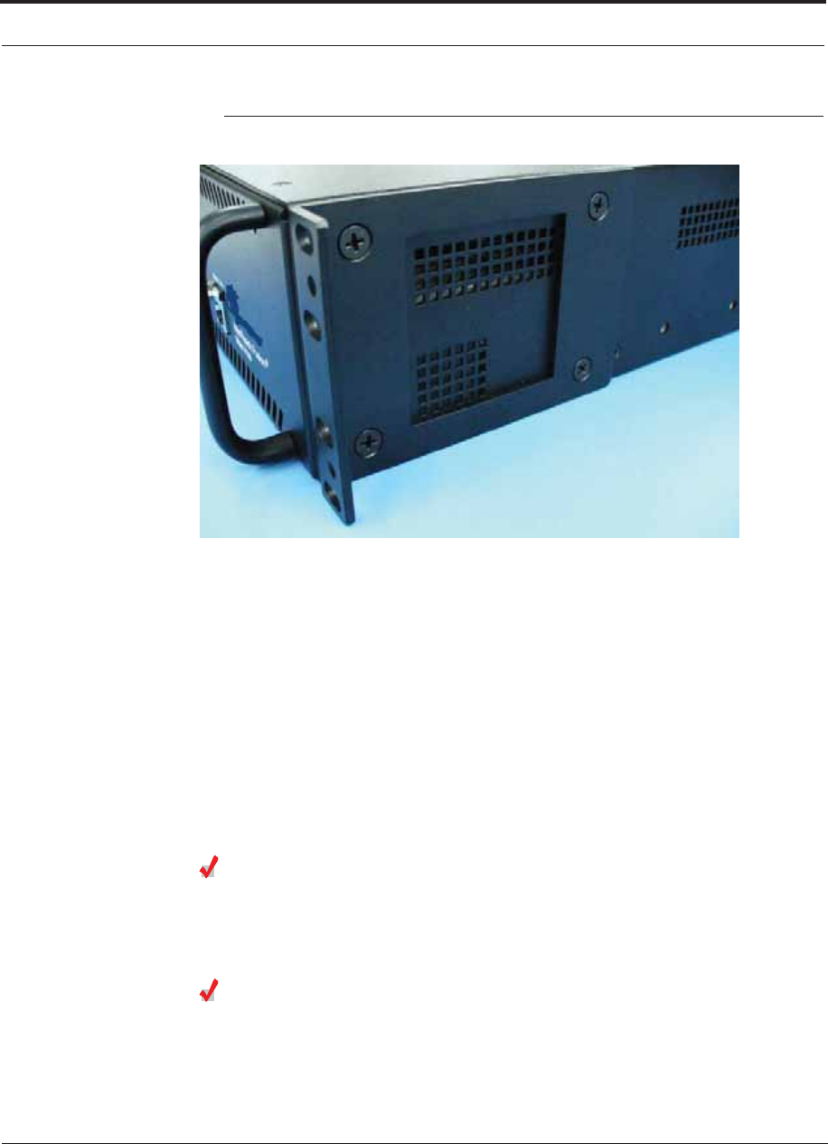
Fusion Wideband Installation Procedures
7-12 InterReach Fusion Wideband Installation, Operation, and Reference Manual
CONFIDENTIAL D-620616-0-20 Rev G
Figure 7-1 Flush Mounting Bracket Detail
Consideration:
• The Fusion Wideband Main Hub is shipped with #10-32 mounting screws.
Another common rack thread is #12-24. Confirm that the mounting screws match
the rack’s threads.
To install the Hub in a rack:
1. Insert spring nuts into rack where needed or use existing threaded holes.
2. Place the Hub into the rack from the front.
3. Align the flange holes with the spring nuts installed in Step 1.
4. Insert the mounting screws in the appropriate positions in the rack.
5. Tighten the mounting screws.
Installing an Optional Cable Manager in the Rack
• Using the screws provided, fasten the cable manager to the rack, immediately
above or below the Main Hub.
Installing a Main Hub Using the 12” Wall-Mounted Rack (PN 4712)
Considerations:
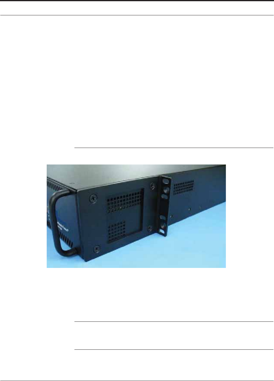
Help Hot Line (U.S. only): 1-800-530-9960 7-13
D-620616-0-20 Rev G CONFIDENTIAL
Fusion Wideband Installation Procedures
• The rack-mounting brackets on the Fusion Wideband Main Hub must be moved to
the recessed mounting position (shown in Figure 7-2) to allow for the required 76
mm (3 in.) rear clearance.
• The maximum weight the bracket can hold is 22.5 kg (50 lbs).
• The bracket is designed to accommodate a Fusion Wideband Main Hub (12 lbs.) or
an Expansion Hub (14.5 lbs.).
• The wall mount bracket should be securely mounted to wall, using the four key slot
mounting holes on the bracket.
Using the Wall Rack-Mounting Option
You can flip the rack mounting brackets, as shown in Figure 7-2, so the hub can be
mounted 76 mm (3 in.) forward in the rack.
Figure 7-2 Bracket Detail For Wall Mount Rack (PN 4712)
To install the Hub to the wall-mounted rack:
1. Attach the wall bracket (PN 4712) to wall the using #10 Pan Head wood screws,
1-1/2” minimum length for mounting in wood studs or 3/4“thick plywood.
The bracket must be positioned so that the Hub will be in a horizontal position
when it is installed. (Refer to Figure 7-2.)
NOTE: If wall stud spacing of 16” is not available, TE recommends that
3/4” plywood be pre-installed to the wall. You can then attach the bracket to
the plywood using the wood screws.
2. Remove both of the rack mounting brackets from the Hub.
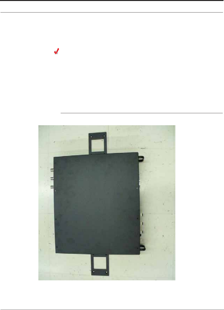
Fusion Wideband Installation Procedures
7-14 InterReach Fusion Wideband Installation, Operation, and Reference Manual
CONFIDENTIAL D-620616-0-20 Rev G
3. Reattach each of the rack mounting brackets to the recessed wall mount position.
4. Install the Hub in the rack using the rack mounting screws.
Installing a Fusion Wideband Main Hub Directly to the Wall
To install the Hub directly to the wall:
1. Pre-install 3/4” plywood to the wall.
2. Mount both of the rack mounting brackets using #10-32 machine screws (refer to
illustration Figure 7-4).
3. Attach the Hub to the wall so the mounting brackets are orientated at the top and
bottom of the wall mounted hub. (Refer to Figure 7-3.)
Figure 7-3 Installing Directly to the Wall
Use two #10 Pan Head wood screws, 1-1/2” length, to secure each bracket to the
plywood. In this orientation the enclosure fans shall face to the left.
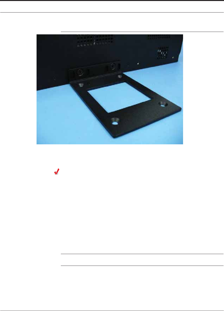
Help Hot Line (U.S. only): 1-800-530-9960 7-15
D-620616-0-20 Rev G CONFIDENTIAL
Fusion Wideband Installation Procedures
Figure 7-4 Using Hub Rack-Mounting Brackets for Direct Wall Installation
Connecting the Fiber Cables to the Main Hub
Considerations:
• Before connecting the fiber cables, confirm that their optical loss does not exceed
the 3 dB optical budget.
• If you are using fiber distribution panels, confirm that the total optical loss of fiber
cable, from the Main Hub through distribution panels and patch cords to the
Expansion Hub, does not exceed the optical budget.
• Make sure the fiber cable’s connectors are SC/APC (angle-polished). Using any
other connector type will result in degraded system performance and may damage
the equipment. (You can use an SC/APC pigtail if the fiber cable’s connectors are
not SC/APC. Refer to“Fusion Splicing of Fiber and Pigtail” on page 7-45. Or, you
can change the fiber’s connector to SC/APC.)
NOTE: Observe all Fiber Port Safety Precautions listed in Section 7.2.3 on page 7-4.

Fusion Wideband Installation Procedures
7-16 InterReach Fusion Wideband Installation, Operation, and Reference Manual
CONFIDENTIAL D-620616-0-20 Rev G
To clean the fiber ports:
You can clean the Hub’s fiber ports using canned compressed air or isopropyl alcohol
and foam tipped swabs.
Considerations:
• If using compressed air:
• The air must be free of dust, water, and oil.
• Hold the can level during use.
• If using isopropyl alcohol and foam tipped swabs:
• Use only 98% pure or more alcohol
Procedure using compressed air:
1. Remove the port’s dust cap.
2. Spray the compressed air away from the unit for a few seconds to clean out the
nozzle and then blow dust particles out of each fiber port.
Procedure using isopropyl alcohol:
1. Remove the connector’s dust cap.
2. Dip a 2.5mm lint-free, foam-tipped swab in isopropyl alcohol and slowly insert
the tip into the connector.
3. Gently twist the swab to clean the port.
4. Insert a dry swab into the port to dry it.
Additionally, you can use compressed air after the alcohol has completely evapo-
rated.
To clean the fiber ends:
Be sure that the fiber cable’s SC/APC connectors are clean and free of dust and oils.
You need lint-free cloths, isopropyl alcohol, and compressed air
1. Moisten a lint-free cloth with isopropyl alcohol.
2. Gently wipe the fiber end with the moistened cloth.
3. Using a dry lint-free cloth, gently wipe the fiber end.
4. Spray the compressed air away from the connector for a few seconds to clean out
the nozzle and then use it to completely dry the connector.
To test the fiber cables:
Perform cable testing and record the results. Test results are required for the final
As-Built Document.

Help Hot Line (U.S. only): 1-800-530-9960 7-17
D-620616-0-20 Rev G CONFIDENTIAL
Fusion Wideband Installation Procedures
To connect the fiber cables:
The fiber cable is labeled with either 1 or 2, or is color-coded. In addition to these
labels, you should add a code that identifies which port on the Main Hub is being
used and which Expansion Hub the cables are intended for. This differentiates the
connectors for proper connection between the Main Hub and Expansion Hubs.
For example:
First pair to Main Hub port 1: 11 (uplink), 12 (downlink);
Second pair to Main Hub port 2: 21 (uplink), 22 (downlink);
Third pair to Main Hub port 3: 31 (uplink), 32 (downlink); and so on.
NOTE: The Fusion Wideband One Port Main Hub (PNs:
FSN-W1-MH-2-1P, FSN-W2-MH-3-1P, FSN-W3-MH-1P, and
FSN-W4-MH-1P) configuration is a cost reduced version of the Fusion
Wideband Main Hub and supports only one Expansion Hub (up to 8 RAUs).
If the fiber jumper is labeled with 1 or 2:
1. Connect 1s to UPLINK ports on the Main Hub.
2. Connect 2s to DOWNLINK ports on the Main Hub.
3. Record which cable number and port number you connected to UPLINK and
DOWNLINK.
This information is needed when connecting the other end of the fiber cable to the
Expansion Hub’s fiber ports.
The fiber port LEDs should be off, indicating that the Expansion Hub(s) are not
connected.
If the fiber jumper is color-coded (for example, “blue” or “red”):
1. Connect “blue” to UPLINK ports on the Main Hub.
2. Connect “red” to DOWNLINK ports on the Main Hub.
3. Record which color and port number you connected to UPLINK and DOWNLINK.
This information is needed when connecting the other end of the fiber cable to the
Expansion Hub’s fiber ports.
The fiber port LEDs should be off, indicating that the Expansion Hub(s) are not
connected.
Fusion Wideband Installation Procedures
7-18 InterReach Fusion Wideband Installation, Operation, and Reference Manual
CONFIDENTIAL D-620616-0-20 Rev G
Making Power Connections
Only trained and qualified personnel should be allowed to install or replace this
equipment.
AC Powered Main Hub
To connect AC power to a Main Hub:
1. Connect the AC power cord to the Main Hub.
2. Plug the power cord into an AC power outlet.
DC Powered Main Hub and Expansion Hub
WARNING: The protective earth connection should be connected
before proceeding with power connections. Confirm the DC power
source is powered off during installation. Damage to hubs may result
if power is connected improperly.
The DC powered Main Hub and Expansion Hub are intended to be powered by a
+48VDC power source. The hubs are designed for 14AWG to 6AWG wire size
connections. Use only UL listed AWM wire, rated 600V and 90 degrees C.
If wires larger than 6AWG are needed from the DC power source, follow local
codes for reducing the wire size at hub connection point.
Follow local codes for routing of power cables to power source.
The unit should be connected to a DC branch circuit breaker. A suitable discon-
nect device must be provided in the DC branch, either a circuit breaker or switch,
that can be employed to disconnect power to the system during servicing.
To connect DC power to a Main Hub or Expansion Hub:
1. Strip 5/8” (16mm) of wire insulation material off each power wire.
2. Insert the +48VDC wire into the compression terminal at the “+” location.
3. Insert the -48VDC wire into the compression terminal at the “-” location.
4. Bare wire ends should be fully inserted into terminal.
5. Use a flat blade screw driver to fasten the wire inside the compression terminal.
6. For the Protective Ground Wire (Figure 7-5), use 14AWG minimum wire with a
#8-32 stud size ring lug.
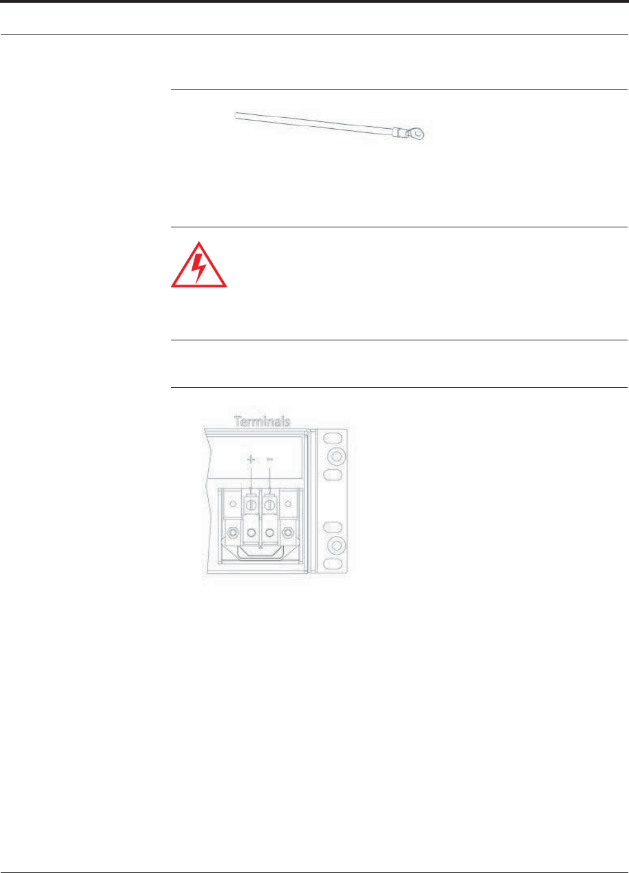
Help Hot Line (U.S. only): 1-800-530-9960 7-19
D-620616-0-20 Rev G CONFIDENTIAL
Fusion Wideband Installation Procedures
Figure 7-5 Protective Ground Wire Connection
WARNING: The warning color code of the power cables depends on
the color coding of the DC power source installed at your site. Color
code standards for DC wiring do not exist. To ensure that the correct
polarity is connected to the hubs, confirm the connection of the
power cables to the + (positive) and - (negative) leads (Figure 7-6) at
the power source.
Figure 7-6 DC Terminals
7. Use the illustrations in Figure 7-7 and Figure 7-9 to connect the power.
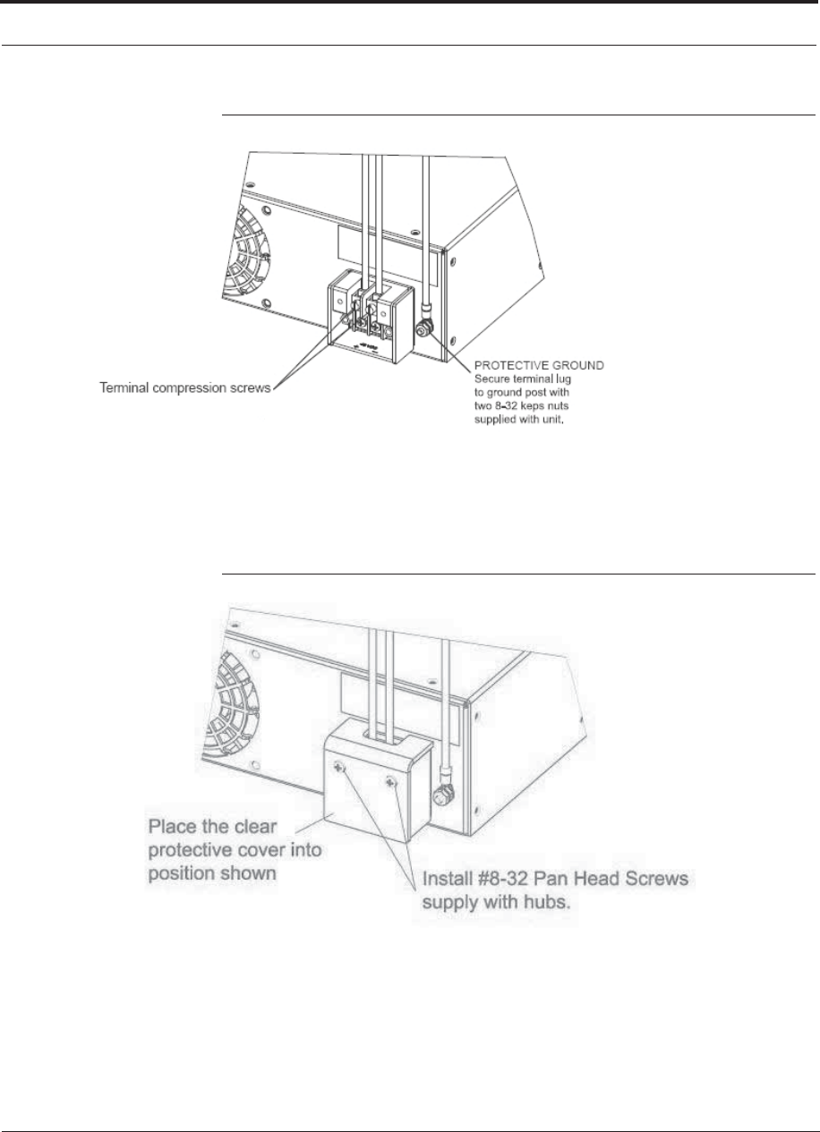
Fusion Wideband Installation Procedures
7-20 InterReach Fusion Wideband Installation, Operation, and Reference Manual
CONFIDENTIAL D-620616-0-20 Rev G
Figure 7-7 Power Screw Locations
8. Install the clear protective cover with the pan head screws as shown in Figure 7-8.
Figure 7-8 Pan Head Screw Location
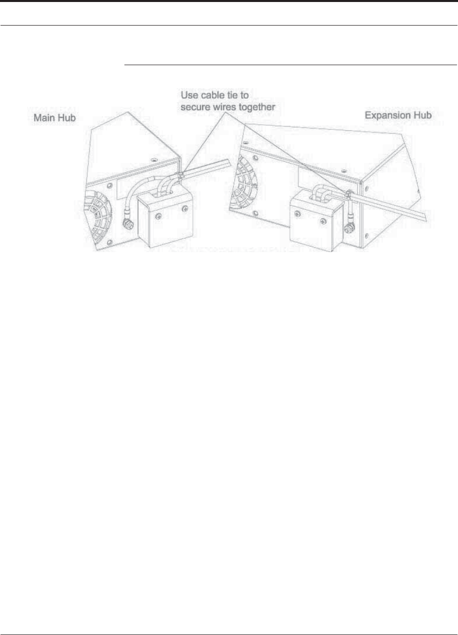
Help Hot Line (U.S. only): 1-800-530-9960 7-21
D-620616-0-20 Rev G CONFIDENTIAL
Fusion Wideband Installation Procedures
Figure 7-9 Recommended Hub Wire Routing
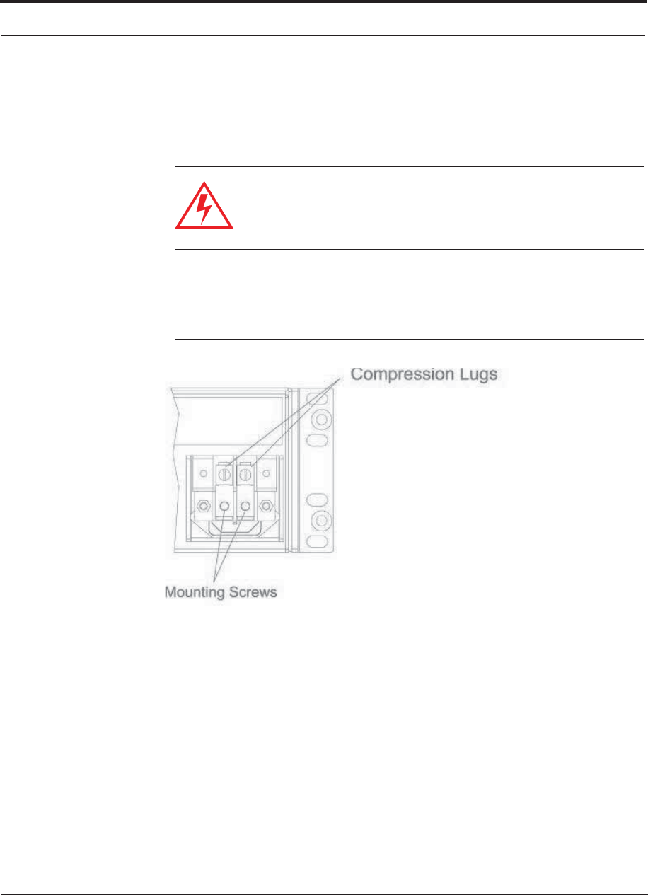
Fusion Wideband Installation Procedures
7-22 InterReach Fusion Wideband Installation, Operation, and Reference Manual
CONFIDENTIAL D-620616-0-20 Rev G
Optional Connection to DC Power Source
This is an optional connection method using ring tongue lugs instead of the com-
pression lugs that are premounted on the terminal block. Use wire selection
instructions previously explained.
WARNING: Before connecting power wires, be sure the power
source is shut off, and the power switch of the hubs are in the OFF
position. Connect the ground wires before connecting the power
wires.
1. Remove the existing compression lugs by first removing the mounting screws as
shown in Figure 7-10.
Figure 7-10 Compression Lug and Mounting Screw Locations
2. Connect the safety ground wire as previously explained and shown in
Figure 7-11. Use 14AWG minimum wire with a #8-32 stud size ring lug as shown
in Figure 7-12.
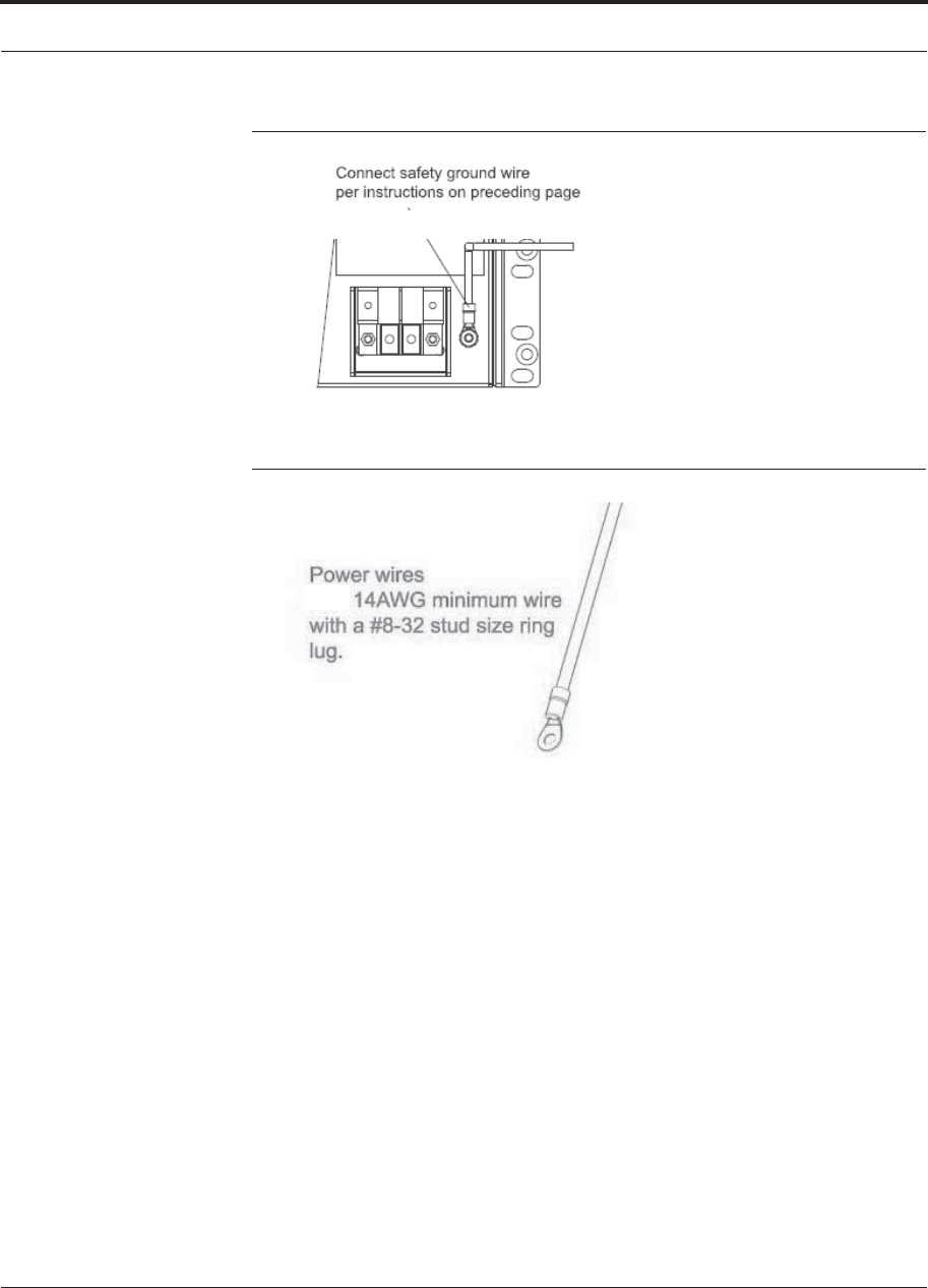
Help Hot Line (U.S. only): 1-800-530-9960 7-23
D-620616-0-20 Rev G CONFIDENTIAL
Fusion Wideband Installation Procedures
Figure 7-11 Grounding Wire Connection
Figure 7-12 Power Wires and Studs
3. Install the finish wires using the proper polarity and secure them with #8-32 pan
head screws previously removed as illustrated in Figure 7-13.
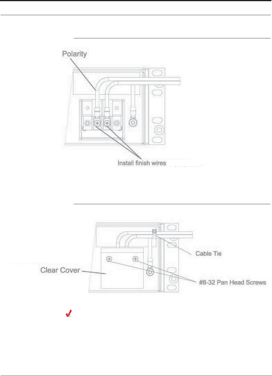
Fusion Wideband Installation Procedures
7-24 InterReach Fusion Wideband Installation, Operation, and Reference Manual
CONFIDENTIAL D-620616-0-20 Rev G
Figure 7-13 Wire Polarity Illustration
4. Attach the clear protective cover and secure it with the two #8-32 pan head screws
supplied with the Hub as shown in Figure 7-14.
Figure 7-14 DC Illustration Detail
Powering On the Main Hub
1. Connect the AC or DC power as explained in “Making Power Connections” on
page 7-18.
2. Turn on the power to the Main Hub and check that all the LED lamps are func-
tioning properly.

Help Hot Line (U.S. only): 1-800-530-9960 7-25
D-620616-0-20 Rev G CONFIDENTIAL
Fusion Wideband Installation Procedures
Upon power-up, the LEDs blinks for five seconds as a visual check that they are
functioning. After the five-second test:
LED states during power on will vary, depending on whether Expansion Hubs are
connected. Refer to Table 7-5 for possible combinations.
Table 7-5 Troubleshooting Main Hub LEDs During Installation
During
Installation
Power On LED State Action Impact
1. Main Hub
power is
On with no
Expansion
Hubs con-
nected.
POWER Off Check AC power; check that the Main Hub power-on
switch is on; replace the Main Hub
The Main Hub is not
powering on.
POWER Red Replace the Main Hub The power supply is
out-of-specification.
PORT LEDs are on
but they
didn’t blink
through all
states
Replace the Main Hub. The micro controller is
not resetting properly;
flash memory cor-
rupted.
PORT Red The port is unusable; replace the Main Hub when
possible.
Fiber sensor fault, do
not use the port.
Off
2. Main Hub
power is
On with
Expansion
Hubs con-
nected and
powered
on.
PORT Off • If the port LEDs do not illuminate, check the fiber
uplink for excessive optical loss.
• If Expansion Hub’s DL STATUS LED is red:
• Verify that the fiber is connected to the correct
port (that is, uplink/downlink)
• Swap the uplink and downlink cables.
• Connect the fiber pair to another port. If the sec-
ond port’s LEDs do not illuminate Green/Red,
replace the Main Hub.
• If the second port works, flag the first port as
unusable; replace the Main Hub when possible.
No uplink optical
power, the Expansion
Hub is not recognized
as being present.
No communication
with the Expansion
Hub.
PORT Red (60 ppm) • If the Expansion Hub DL STATUS LED is red,
check the downlink fiber cable for excessive opti-
cal loss.
• Connect the fiber pair to another port. If the sec-
ond port’s LEDs do not illuminate Green/Red,
replace the Main Hub.
• If the second port works, flag the first port as
unusable; replace the Main Hub when possible.
No communication
with the Expansion
Hub.
PORT Red The Expansion Hub or connected RAU reports a fault
Use AdminManager to determine the problem.
The Expansion Hub or
one or more RAUs are
off-line.
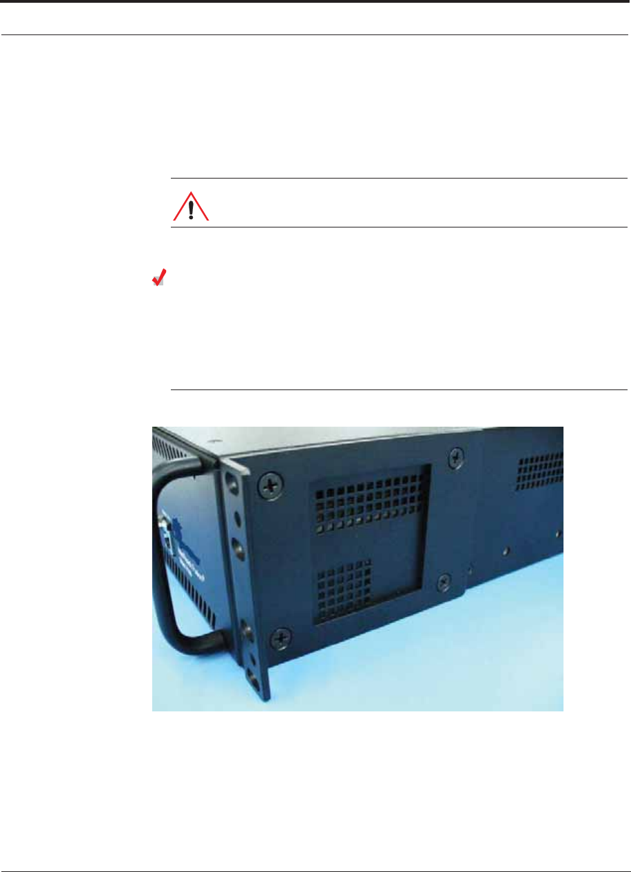
Fusion Wideband Installation Procedures
7-26 InterReach Fusion Wideband Installation, Operation, and Reference Manual
CONFIDENTIAL D-620616-0-20 Rev G
7.4.2 Installing Expansion Hubs
The Expansion Hub (2U high) can be installed in a standard 19 in. (483 mm) equip-
ment rack or in a wall-mountable equipment rack that is available from TE. Allow a
clearance of 76 mm (3 in.) front and rear and 51 mm (2 in.) sides for air circulation.
No top and bottom clearance is required.
CAUTION: Install Expansion Hubs in indoor locations only.
Installing an Expansion Hub in a Rack
Consideration:
• The Expansion Hub is shipped with #10-32 mounting screws. Another common
rack thread is #12-24. Confirm that the mounting screws match the rack’s threads.
Figure 7-15 Flush Mounting Bracket Detail
To install the hub in a rack:
1. Insert spring nuts into the rack where needed or use existing threaded holes.
2. Place the Expansion Hub into the rack from the front.
3. Align the flange holes with the spring nuts installed in Step 1.
4. Insert the mounting screws in the appropriate positions in the rack.
5. Tighten the mounting screws.
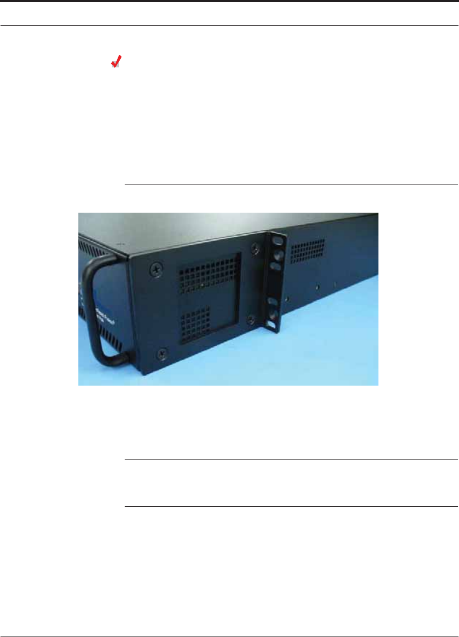
Help Hot Line (U.S. only): 1-800-530-9960 7-27
D-620616-0-20 Rev G CONFIDENTIAL
Fusion Wideband Installation Procedures
Installing an Expansion Hub Using the 12” Wall-Mounted Rack
Considerations:
• The rack (PN4712) is 305 mm (12 in.) deep. The Expansion Hub is 381 mm (15
in.) deep. You must move the rack mounting brackets on the Expansion Hub, as
shown in Figure 7-16) to the center mounting position to allow for the 76 mm (3
in.) rear clearance that is required.
• The maximum weight the rack can hold is 22.5 kg (50 lbs).
Figure 7-16 Bracket Detail For Wall Mount Rack (PN 4712)
To install the hub in a wall-mounted rack:
1. Attach the equipment rack to the wall using the screws that are provided.
The rack must be positioned so that the Expansion Hub will be in a horizontal
position when it is installed.
NOTE: If wall stud spacing of 16” is not available, TE recommends that
3/4” plywood be pre-installed to the wall. You can then attach the bracket to
the plywood using the wood screws.
2. Remove both of the rack mounting brackets from the Hub.
3. Reattach each of the rack mounting brackets to the recessed wall mount position
(Figure 7-16).
4. Install the Hub in the rack using the rack mounting screws.
5. Tighten the mounting screws.
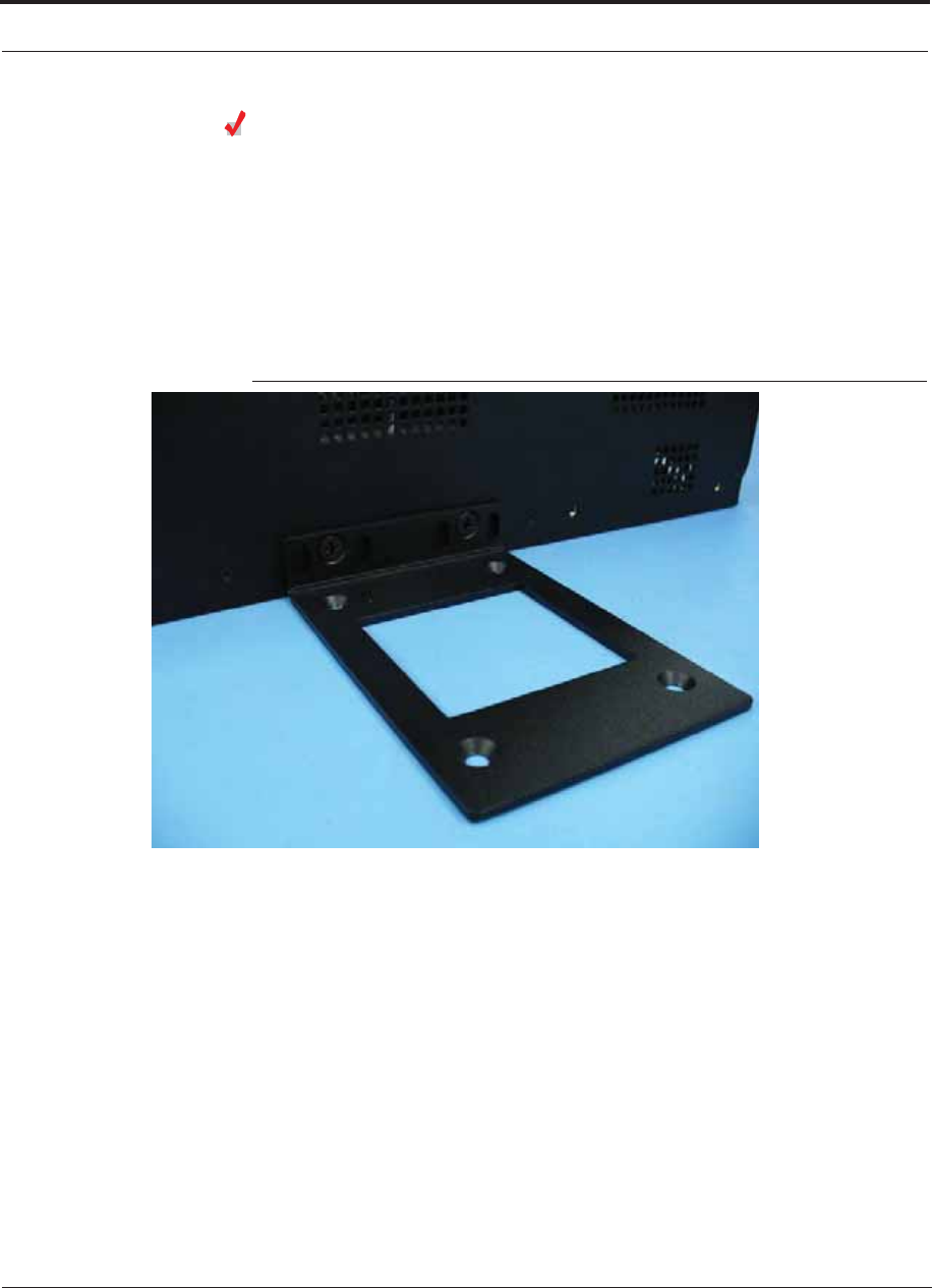
Fusion Wideband Installation Procedures
7-28 InterReach Fusion Wideband Installation, Operation, and Reference Manual
CONFIDENTIAL D-620616-0-20 Rev G
Installing a Fusion Wideband Expansion Hub Directly to the Wall
To install the Hub directly to the wall:
1. Pre-install 3/4” plywood to the wall.
2. Mount both of the rack mounting brackets using #10-32 machine screws (refer to
illustration Figure 7-17).
3. Attach the Hub to the wall so the mounting brackets are orientated at the top and
bottom of the wall mounted hub. (Refer to Figure 7-18.)
Figure 7-17 Using Hub Rack-Mounting Brackets for Direct Wall Installation
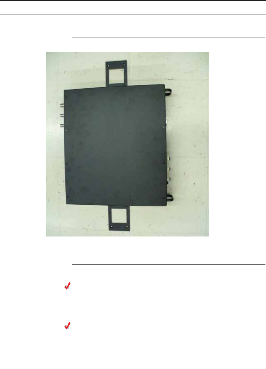
Help Hot Line (U.S. only): 1-800-530-9960 7-29
D-620616-0-20 Rev G CONFIDENTIAL
Fusion Wideband Installation Procedures
Figure 7-18 Installing Directly to the Wall
NOTE: Leave the dust caps on the fiber ports until you are ready to connect the fiber
optic cables.
Installing an Optional Cable Manager in the Rack
• Using the screws provided, fasten the cable manager to the rack, immediately
above or below the Expansion Hub.
Powering On the Expansion Hub
1. Connect the AC or DC power as explained in “Making Power Connections” on
page 7-18.

Fusion Wideband Installation Procedures
7-30 InterReach Fusion Wideband Installation, Operation, and Reference Manual
CONFIDENTIAL D-620616-0-20 Rev G
2. Turn on the power to the Expansion Hub and check that all the LED lamps are
functioning properly.
Upon power-up, the LEDs blinks for five seconds as a visual check that they are
functioning. After the five-second test:
• The POWER and UL STATUS LEDs should be green.
– If the uplink fiber is not connected, the UL STATUS LED turns red indicating
that there is no communication with the Main Hub.
• The E-HUB STATUS and DL STATUS LEDs should be red.
• All port LEDs should be off because no RAUs are connected yet.
Connecting the Fiber Cables to the Expansion Hub
Considerations:
• Before connecting the fiber cables, confirm that their optical loss does not exceed
3 dB optical budget. RL is less than -60dB.
• If fiber distribution panels are used, confirm that the total optical loss of fiber
cable, from the Main Hub through distribution panels and patch cords to the
Expansion Hub, does not exceed the optical budget.
• Make sure the fiber cable’s connectors are SC/APC (angle-polished).Using any
other connector type will result in degraded system performance and may damage
the equipment. (You can use an SC/APC pigtail if the fiber cable’s connectors are
not SC/APC, refer to “Fusion Splicing of Fiber and Pigtail” on page 7-45, or
replace the connectors.)
NOTE: Observe all Fiber Port Safety Precautions listed in Section 7.2.3 on page 7-4.
To connect the fiber cables:
The fiber cable is labeled with either 1 or 2, or is color-coded. For proper connection
between the Main Hub ports and the Expansion Hub ports, refer to the numbering or
color-coded connections you recorded when installing the Main Hub(s).
If the fiber jumper is labeled with 1 or 2:
1. Connect 2 to DOWNLINK on Expansion Hub.
The DL STATUS LED should turn green as soon as you connect the fiber. If it does
not, there is a downlink problem. Make sure you are connecting the correct cable
to the port.
2. Connect 1 to UPLINK on Expansion Hub.
The UL STATUS LED turns green on the first Main Hub communication. It may
take up to 20 seconds to establish communication.

Help Hot Line (U.S. only): 1-800-530-9960 7-31
D-620616-0-20 Rev G CONFIDENTIAL
Fusion Wideband Installation Procedures
The Expansion Hub’s E-HUB STATUS LED turns green when the Main Hub sends
it the frequency band command.
If the UL STATUS and E-HUB STATUS LEDs do not turn green/green, check the
Main Hub LEDs. Refer to page 7-25, item 2 in Table 7-5.
If the fiber jumper is color-coded (for example, “blue” or “red”):
1. Connect “red” to DOWNLINK on Expansion Hub.
The DL STATUS LED should turn green as soon as you connect the fiber. If it does
not, there is a downlink problem. Make sure you are connecting the correct cable
to the port.
2. Connect “blue” to UPLINK on Expansion Hub.
The UL STATUS LED turns green on the first Main Hub communication. It may
take up to 20 seconds to establish communication.
The Expansion Hub’s E-HUB STATUS LED turns green when the Main Hub sends
it the frequency band command.
If the UL STATUS and E-HUB STATUS LEDs do not turn green/green, check the
Main Hub LEDs. See page 7-25, item 2 in Table 7-5.
Connecting the 75 Ohm CATV Cables
Considerations:
• Verify that the cable has been tested and the test results are recorded. This informa-
tion is required for the As-Built Document.
• Verify that only captive centerpin F connectors are used on the solid copper center
conductor CATV cable from CommScope (or equivalent).
• Verify that the CATV cable is labeled with:
• Fusion Wideband Expansion Hub port number being used
• RAU identifier
• Carrier (for multiple operator systems)
To connect the CATV cables:
1. Connect the CATV cables to the F ports according to the labels on the cables.
The STATUS LEDs should be off because the RAUs are not connected at the other
end of the CATV cable.
2. Record which cable you are connecting to which port (that is, from the label on
the cable).
This information is required for the As-Built Document.
3. Tie-off the cables or use the optional cable manager to avoid damaging the con-
nectors because of cable strain.

Fusion Wideband Installation Procedures
7-32 InterReach Fusion Wideband Installation, Operation, and Reference Manual
CONFIDENTIAL D-620616-0-20 Rev G
Troubleshooting Expansion Hub LEDs During Installation
• All Expansion Hub PORT LEDs with RAUs connected should indicate Green/Red.
This indicates that the RAU is powered on and communication has been estab-
lished.
• The Expansion Hub UL STATUS LED should be Green.
Table 7-6 Troubleshooting Expansion Hub LEDs During Installation
During
Installation LED State Action Impact
1. Expansion
Hub power
is On and no
RAUs are
connected
POWER Off Check AC power; make sure the
Expansion Hub power-on switch
is on; replace the Expansion Hub.
The Expansion Hub is not
powering on.
PORT LEDs are on but
didn’t blink through
all states.
Replace the Expansion Hub. The Microcontroller is not
resetting properly; flash
memory corrupted.
PORT Flashing Red
(6 PPM)
Port unusable; replace the Expan-
sion Hub when possible.
Current sensor fault; do not
use the port.
UL STATUS Red, after power-up
blink
Replace the Expansion Hub. The Expansion Hub laser is
not operational; no uplink
between the Expansion Hub
and Main Hub.
UL STATUS
Red
Check the Main Hub LEDs
Refer to page 7-25, item 2 in
Table 7-5.
Use AdminBrowser to determine
the problem.
No communication with
Main Hub.
DL STATUS Red Check the downlink fiber for opti-
cal power; verify that the cables
are connected to correct ports
(that is, uplink/downlink)
Check the Main Hub LEDs. Refer
to page 7-25, item 2 in Table 7-5.
No downlink between the
Expansion Hub and Main
Hub.
2. Expansion
Hub power
is On and
RAUs are
connected
PORT Off Check the CATV cable. Power is not getting to the
RAU.
PORT Flashing Red
(60 PPM)
Test the CATV cable. If the cable
tests OK, try another port. If the
second port’s LEDs are Red/Off,
replace the RAU. If the second
RAU doesn’t work; replace the
Expansion Hub.
Power levels to RAU are not
correct; communications are
not established.
If the second port works, flag
the first port as unusable;
replace EH when possible.
PORT Red Use AdminBrowser to determine
the problem.
RAU is off-line.

Help Hot Line (U.S. only): 1-800-530-9960 7-33
D-620616-0-20 Rev G CONFIDENTIAL
Fusion Wideband Installation Procedures
7.4.3 Installing RAUs
CAUTION: Install RAUs in indoor locations only. Do not con-
nect an antenna that is installed in an outdoor location to an RAU.
For outdoor installations, a protective enclosure is required.
Installing RAUs
Mount all RAUs in the locations marked on the floor plans.
Considerations:
• You can place the unit, without its fastening hardware, on a flat surface, such as a
shelf, desk, cabinet, or any other horizontal surface that allows stable placement
with the mounting base facing down to the mounting surface. For mounting to
other locations (that is, walls, ceilings, poles) the RAU must be securely mounted
using the 4 slotted mounting holes provided with #6 diameter fasteners. This
method of mounting must securely hold a minimum of 7 lbs. load.
• Attach the RAU securely to a stationary object (that is, a wall, pole, or ceiling tile).
• For proper ventilation:
• Keep at least 76 mm (3 in.) clearance around the RAU to ensure proper venting.
• Do not stack RAUs on top of each other.
• Always mount the RAU with the solid face (containing the mounting holes)
against the mounting surface.
• For the 800/850/1900 MHz RAU (P/N: FSN-W2-808519-1), make sure the 800
MHz iDEN antenna and the 850/1900 MHz antenna are separated by enough space
to reduce signal interference between the 800 and 850 MHz bands. Refer to
“800/850 MHz Isolation Requirements” on page 7-34 for the recommended dis-
tance between antennas.
Installing Passive Antennas
Refer to the manufacturer’s installation instructions to install passive antennas.
Location
Passive antennas are usually installed below the ceiling. If they are installed above
the ceiling, you must consider the additional loss due to the ceiling material when
estimating the antenna coverage area.
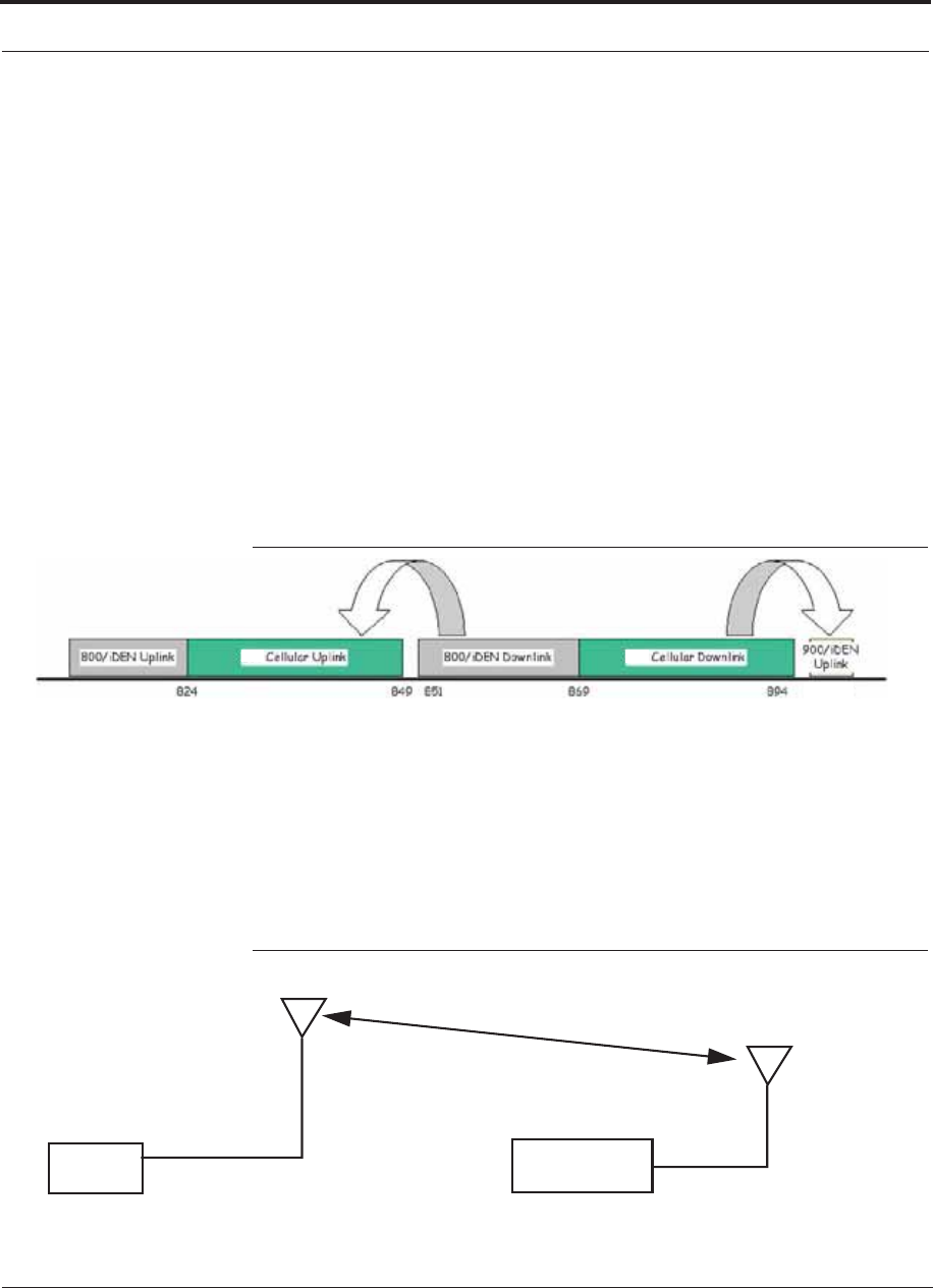
Fusion Wideband Installation Procedures
7-34 InterReach Fusion Wideband Installation, Operation, and Reference Manual
CONFIDENTIAL D-620616-0-20 Rev G
800/850 MHz Isolation Requirements
When deploying any RF system, give special attention to preventing receiver block-
ing or desensitization by out-of-band transmitters. Typically, sharp filters in the
receiver front-end will reduce the interfering transmitters to tolerable levels. In select
cases, the interferers may occupy a frequency band that is directly adjacent to the
receiving band and cannot be adequately rejected by filtering. The only recourse in
these situations is to provide sufficient isolation by physically separating the interfer-
ing transmitters and receivers.
iDEN occupies spectrum at both 800 MHz and 900 MHz (Tx:851–869/Rx:806–824
and Tx:935–941 /Rx:896–902), while the Cellular A and B carriers share a single 850
MHz block (Tx:869–894/Rx:824–849). The combination of these frequency bands,
800/900 MHz iDEN and 850 MHz Cellular, result in uplink (BTS receive) bands that
are adjacent to downlink (BTS transmit) bands. Figure 7-19 depicts these nearly con-
tiguous bands, with arrows indicating the interfering downlink and receiving uplink
bands.
Figure 7-19 800/850 MHz Spectrum
850 850
896-902
Installation of an in-building distributed antenna system (DAS) to provide coverage
for both 800/900 MHz iDEN and 850 MHz Cellular must account for these down-
link-to-uplink interference issues and provide adequate isolation.
TE offers the following guidelines toward achieving the proper amount of isolation
when deploying TE Fusion DAS products.
Figure 7-20 Fusion Wideband 800/850/1900 MHz RAU Antenna Placement
Guideline
>d
Band 1
800 MHz Band 2/3
850/1900 MHz

Help Hot Line (U.S. only): 1-800-530-9960 7-35
D-620616-0-20 Rev G CONFIDENTIAL
Fusion Wideband Installation Procedures
800 MHz iDEN Downlink and 850 MHz Cellular Uplink
A 2 MHz frequency gap (851 – 849 MHz) separates the 800 iDEN downlink and 850
Cellular uplink frequency bands. Because of this narrow spacing, 800 iDEN down-
link intermodulation products may fall within the 850 Cellular uplink band. In addi-
tion, 800 iDEN downlink signals near the lower edge of the band at 851 MHz may
cause the 850 Cellular uplink automatic level control (ALC) circuitry in the RAU to
engage and thereby reduce uplink gain.
To prevent either of these conditions, use the following guidelines:
• In-band 800 iDEN intermodulation products < -90dBm
• Lower frequency 800 iDEN signals < –30dBm for Fusion
Given a typical DAS configuration (4 iDEN carriers, omni-directional antennas, line
of sight), these guidelines translate to an antenna spacing (d) of 6 – 9 meters.
850 MHz Cellular Downlink and 900 MHz iDEN Uplink
A 2 MHz frequency gap (896 – 894 MHz) separates the 850 Cellular downlink and
900 iDEN uplink frequency bands. Because of this narrow spacing, 850 Cellular
downlink intermodulation products may fall within the 900 iDEN uplink band. In
addition, 850 Cellular downlink signals near the upper edge of the band at 894 MHz
may cause the 900 iDEN uplink ALC to engage and thereby reduce uplink gain.
To prevent either of these conditions, use the following guidelines:
• In-band 850 Cellular intermodulation products < -90dBm
• Upper frequency 850 Cellular signals < –30dBm for Fusion
Given a typical DAS configuration (6 CDMA carriers for Fusion, omni-directional
antennas, line of sight), these guidelines translate to an antenna spacing (d) of 8-14
meters.
Connecting the Antenna to the RAU
Connect a passive multi-band antenna to the N connector on the RAU using coaxial
cable with the least amount of loss possible.
CAUTION: Firmly hand-tighten the N connector – DO NOT
over-tighten the connector.
Connecting the CATV Cable
Considerations:
• Verify that the cable has been tested and the test results are recorded. This informa-
tion is required for the As-Built Document.

Fusion Wideband Installation Procedures
7-36 InterReach Fusion Wideband Installation, Operation, and Reference Manual
CONFIDENTIAL D-620616-0-20 Rev G
• Verify that only captive centerpin 75 Ohm Type-F connectors are used on the solid
copper center conductor CATV 75 Ohm cable.
• Verify that the CATV cable is labeled with:
• Fusion Wideband Main Hub port number being used
• RAU identifier
• Carrier (for multiple operator systems)
To connect the CATV cable:
1. Connect the CATV cables to the F female port on the RAU according to the label
on the cable.
Power is supplied by the Fusion Wideband Main Hub over the CATV cable con-
ductors. Upon power up, the LEDs will blink for two seconds as a visual check
that they are functioning. After the two-second test:
• The LINK LED should be green indicating it is receiving power and communi-
cations from the Fusion Wideband Main Hub.
• The ALARM LED should be red until the Fusion Wideband Main Hub issues the
band command, within about 20 seconds, then it should be green.
2. Record which cable you are connecting to the RAU (from the label on the cable).
This information is required for the As-Built Document.
3. Tie-off cables or use the optional cable manager to avoid damaging the connectors
because of cable strain.
7.4.3.1 Troubleshooting Using RAU LEDs During Installation
• The LINK LED should be green and remain green for longer than 90 seconds. The
ALARM LEDs are red when the system band has not been programmed.

Table 7-7 Troubleshooting RAU LEDs During Installation
During
Installation LED State Action Impact
The RAU is connected
to the Fusion Wide-
band Expansion Hub,
which is powered on
LINK Off Check CATV cable. No power to the RAU.
ALARM Off
LINK Green • Check CATV cable
• Check Hub LEDs
Refer to page 7-32, item 2 in
Table 7-6.
• Use AdminBrowser to determine the
problem.
The RAU is off-line.
ALARM Red
LINK Red from
green, after
cables are
connected for
60 seconds
• Check CATV cable.
• Check the Hub LEDs.
• Use AdminBrowser to determine the
problem.
No communications
between the RAU and the
Hub.
ALARM Red
Help Hot Line (U.S. only): 1-800-530-9960 7-37
D-620616-0-20 Rev G CONFIDENTIAL
Fusion Wideband Installation Procedures
7.4.4 Configuring the Fusion Wideband System
Before the system can operate properly, use AdminBrowser to program the Fusion
Wideband Main Hub with the frequency bands that are to be distributed. The Hub
must be programmed with the same frequencies as the RAU used.
NOTE: The frequency bands should automatically be set on power up and
this step should not be required.
Considerations:
• The AdminBrowser software, described in the AdminBrowser User Manual
(PN D-620607-0-20), must be running on a PC/laptop.
• Crossover Ethernet cable with male connectors required.
Connecting a PC to the Main Hub to Run AdminBrowser
1. Connect the AC power cord to the Hub.
Make sure the Hub is grounded through the ground lug on the AC power and
the frame ground lug as required. The warranty does not cover damage
caused when an ungrounded Hub is powered on.
2. Plug the power cord into an AC power outlet.
3. Verify that all cables are properly connected on the Hub.
4. Turn on the power to the Hub.
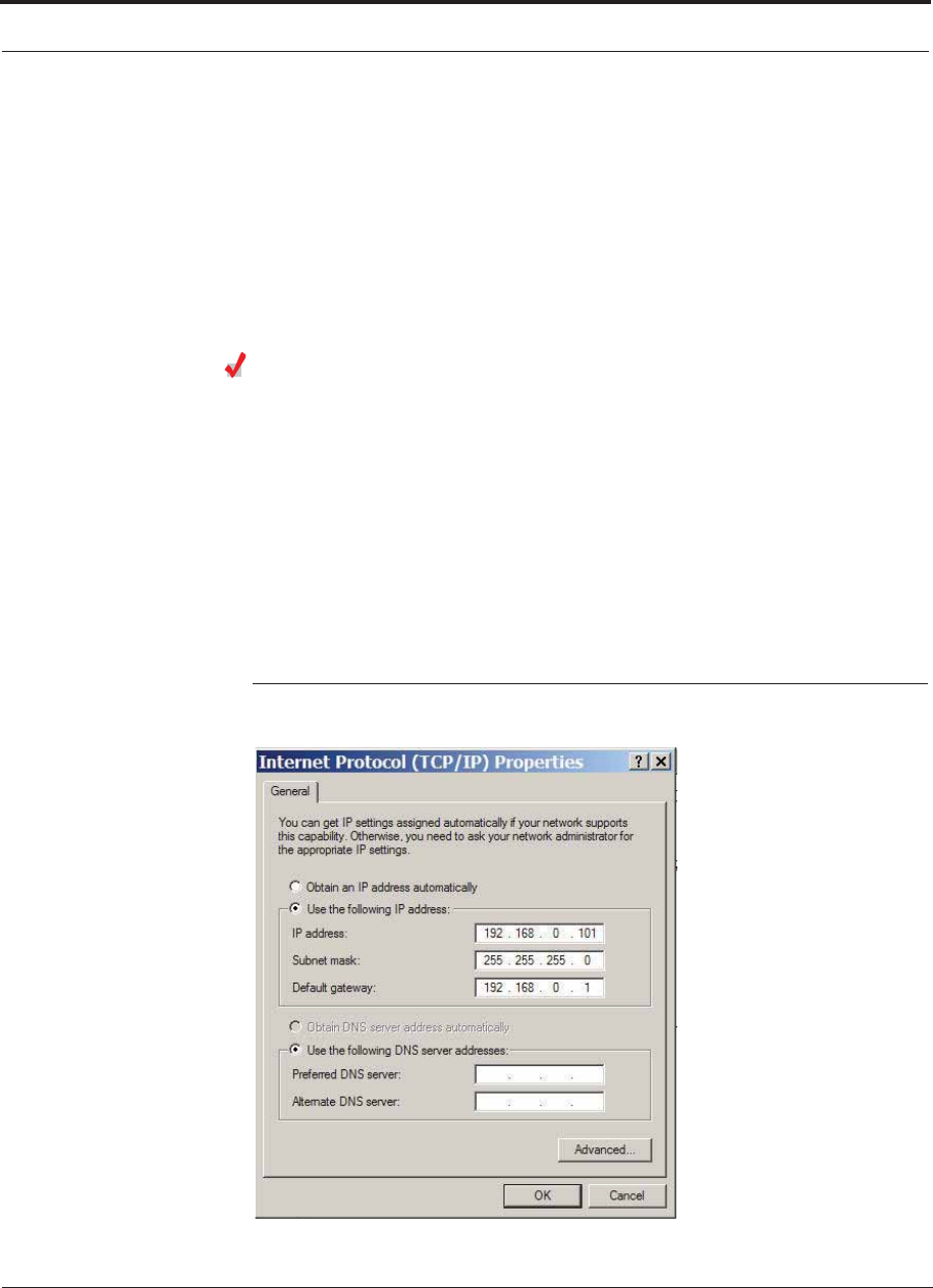
Fusion Wideband Installation Procedures
7-38 InterReach Fusion Wideband Installation, Operation, and Reference Manual
CONFIDENTIAL D-620616-0-20 Rev G
All LEDs blink through the power up sequence. At each port where an RAU is
detected (drawing current), the port LEDs lights green. The Fusion Wideband
STATUS LED is orange during system boot and should turn green after about 90
seconds if it finds no faults. This state indicates the band’s are not programmed
and provides feedback on the status of the RAU connections.
The LEDs blink for 20 seconds as a visual check that they are functioning.
5. Connect the cross-over Ethernet cable to the PC/laptop and then to the RJ-45
100-BASE-T port on the Hub’s front panel.
Programming the Main Hub Using AdminBrowser
• Connect the provided TCP/IP crossover cable to the laptop and then to the
Admin/LAN RJ-45 port on the Fusion Wideband Main Hub’s front panel.
• Turn on the laptop and start the Fusion Wideband Main Hub.
Windows 2000
1. Right-click My Network Places and select Properties.
2. Highlight Internet Protocol (TCP/IP) and click Properties. A window similar to
the Figure 7-21 appears.
Figure 7-21 Internet Protocol (TCP/IP) Properties Window
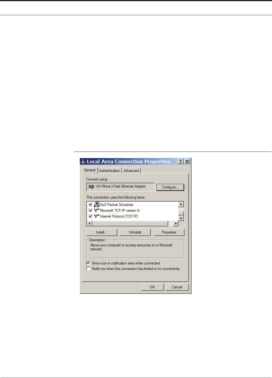
Help Hot Line (U.S. only): 1-800-530-9960 7-39
D-620616-0-20 Rev G CONFIDENTIAL
Fusion Wideband Installation Procedures
3. Make note of the current IP address, Subnet mask, and Default gateway, if they
are configured. You will need to re-enter them after you have configured the
Fusion Wideband Main Hub.
4. Select Use the following IP address.
5. Change the IP address to 192.168.0.101
6. Change the Subnet mask to 255.255.255.0
7. Change the Default gateway to 192.168.0.1
8. Click OK twice. You may be asked if you want to reboot your computer. If so,
click Yes.
Windows XP
1. Click Start>Settings>Network Connections>Local Area Connection. The win-
dow shown in Figure 7-22 appears.
Figure 7-22 Local Area Connection Properties Window
2. In the This connection uses the following items, scroll down to and select
Internet Protocol (TCP/IP) and click Properties.
3. Perform steps 3 through 8 in the preceding section.
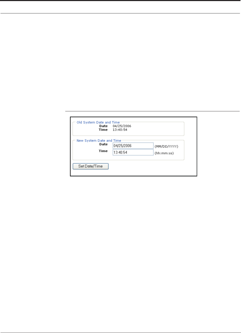
Fusion Wideband Installation Procedures
7-40 InterReach Fusion Wideband Installation, Operation, and Reference Manual
CONFIDENTIAL D-620616-0-20 Rev G
Using AdminBrowser
To access Fusion Wideband using AdminBrowser, use the following steps:
1. Make sure the Main Hub “Status” LED is green.
2. Launch your web browser, type
Https://192.168.0.100
in the URL line, and click Go.
3. When AdminBrowser appears, log in using the default user ID: operator, and the
default password: password.
4. Click System Configuration and then click Set Date/Time. A window similar to
Figure 7-23 appears.
Figure 7-23 Set Time and Date Window
5. Enter the desired time and date in the format indicated in the window and click
Set Date/Time. A window appears requiring you to reboot the system for the new
date and time to take effect.
6. Select the Fusion Wideband Main Hub and click Install/Configure System. A
window similar to the Figure 7-24 appears.
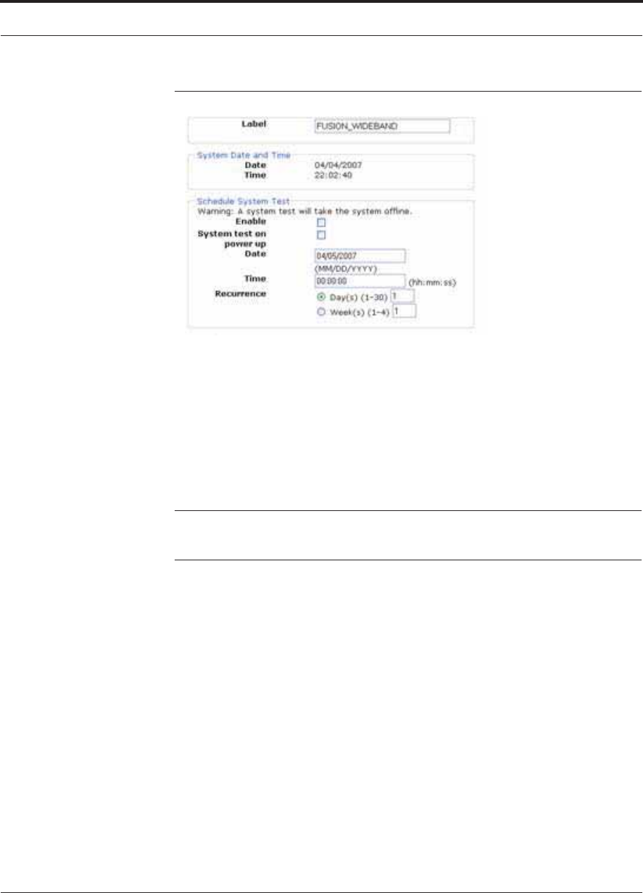
Help Hot Line (U.S. only): 1-800-530-9960 7-41
D-620616-0-20 Rev G CONFIDENTIAL
Fusion Wideband Installation Procedures
Figure 7-24 AdminBrowser Configuration Window
7. If desired, type in a label.
The label is the system name displayed next to the icons and used in messages.It
can be up to 32 characters long depending upon the firmware version.
The default system label is “Fusion” and will be used if you enter nothing.
8. Use the next section to schedule a System Test.
This section allows you to do the following:
• Click the check box to enable this feature.
• Click the check box to cause system test on power up.
NOTE: System test will always be run on power up when this box is
checked, even if a scheduled system is not enabled.
• Enter values to schedule the date and time of the next system test.
• Enter values to specify the recurrence of the test by day or by week.
Schedule System Test allows periodic, automatic execution of the system
end-to-end test. Just like Perform System Test, a Schedule System Test suspends
normal service for the duration of the test; calls are dropped, and no new calls can
be established during the test. Test duration depends on the configuration (number
of RAUs) and requires one or two minutes to complete.
After completion of the system test, the scheduled system test time is updated to
the next test time.
9. Use the scroll bar on the left side of the page to scroll down to view the rest of the
page as shown in Figure 7-25 (Non-WiMAX Installations) and Figure 7-26
(WiMAX Installations only).
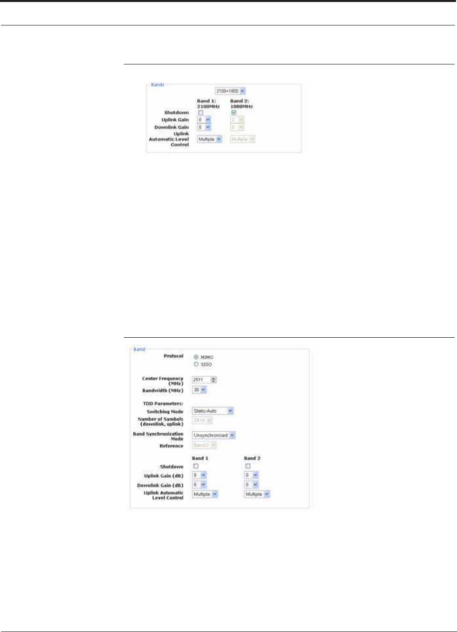
Fusion Wideband Installation Procedures
7-42 InterReach Fusion Wideband Installation, Operation, and Reference Manual
CONFIDENTIAL D-620616-0-20 Rev G
Figure 7-25 AdminBrowser Configuration Window for Non WiMAX
10. In the Band area, do the following:
• You should not have to select the bands. The system self configures the band
by validating that all the RAUs connected are the same type.
• When both bands are not configured, use the Shutdown check box. The system
ignores any alarms generated from the shutdown bands.
• Use the pull-down to specify the Uplink and Downlink gain for each band. You
can set system gain within the specified range in 1 dB increments.
• Use the pull-down to set the Uplink Automatic Level Control to either “Single”
or “Multiple” for each band in the system. (The default is “Multiple.”
11. FOR WiMAX INSTALLATIONS ONLY: Use the scroll bar on the left side of
the page to scroll down to view the next part of the windows shown in
Figure 7-26.
Figure 7-26 AdminBrowser Configuration Window WiMAX ONLY
In the Band area, do the following:
• Select the Protocol mode: This configures the system to support WiMAX
radios that are one of the following:
MIMO (multiple in-multiple out)
SISO (single in-single out). The default is “MIMO”.

Help Hot Line (U.S. only): 1-800-530-9960 7-43
D-620616-0-20 Rev G CONFIDENTIAL
Fusion Wideband Installation Procedures
• Select the Center Frequency and Bandwidth using the arrows next to the fields.
The center frequency is the frequency of WiMAX radios being used for Band 1
and Band 2.
NOTE: In MIMO mode, the frequencies are the same. The system can be
configured to support 2-SISO radios, one per band, across any 30 MHz
within the WiMAX band.
• Use the pull-down to select the Switching Mode. This indicates whether or not
the downlink-to-uplink frame duration is known. The two options are as fol-
lows:
–Static-Selected: This mode specifies the number of symbols. Use the
pull-down to select the symbol in the downlink and uplink portions of the
frame. (The default is “29,18”.) In this mode, the system always switches
from the downlink to the uplink path after the downlink portion of the frame
has elapsed.
–Static-Auto: This mode causes the system to attempt to determine the cor-
rect switching time, then enforce it. (The default is “Static-Auto”)
• Select the Band Synchronization Mode with the pull-down. This parameter can
be configured to operate as one of the following:
–Synchronized: This mode is for cases like MIMO, where the timing for
both bands is the same. In this mode, the system always switches between
uplink and downlink simultaneously for both bands.
–Unsynchronized: In this mode, the two WiMAX bands switch indepen-
dently from each other. (The default is “Unsynchronized”)
•Reference: Select which WiMAX radio band will be used for frame reference.
• When any band is not configured, use the Shutdown check box. The system
ignores any alarms generated from the shutdown bands.
• Use the pull-down to specify the Uplink and Downlink gain for each band. You
can set system gain within the specified range in 1 dB increments.
• Use the pull-down to set the Uplink Automatic Level Control to either “Single”
or “Multiple” for each band in the system. (The default is “Multiple.”)
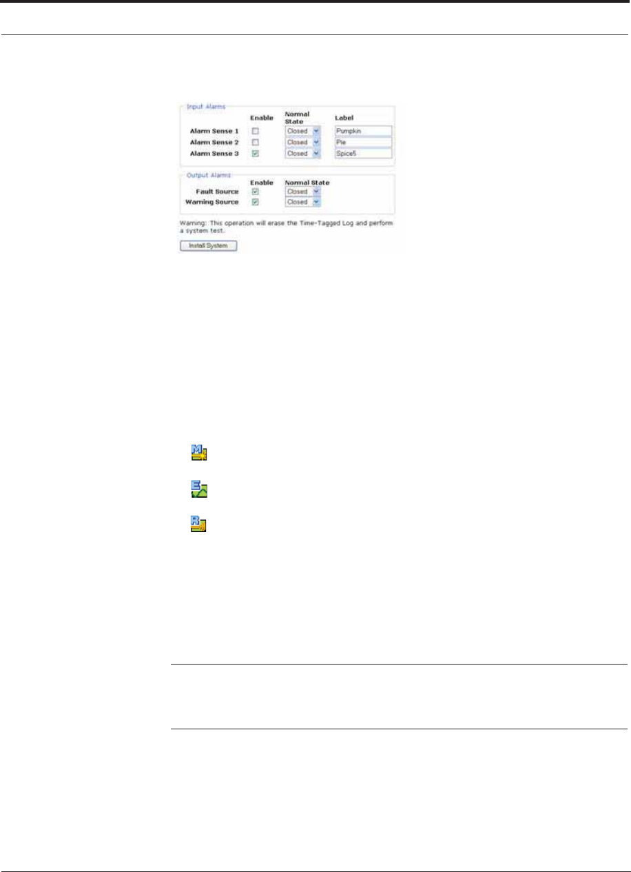
Fusion Wideband Installation Procedures
7-44 InterReach Fusion Wideband Installation, Operation, and Reference Manual
CONFIDENTIAL D-620616-0-20 Rev G
12. Use the scroll bar on the left side of the window to scroll down to view the rest of
the window as shown below.
13. In the Input/Output Alarms area, do the following for each Alarm Sense:
• Enable each Alarm Sense by using the check box.
• Use the pull-down to set the Normal State to Closed or Opened. (The default is
“Closed.”
• Assign a label to each alarm sense.
14. When you have completed inputting the desired information, click Install System
to configure the system.
During configuration all disconnect statuses are cleared for attached RAUs; the
frequency band, gain, and system label are set; logs are cleared; the system test is
performed; and finally the system tree is refreshed. The icons should be:
Indicating that the band is correctly set on the Main Hub.
Indicating that the band is correctly set on the Expansion Hub.
Indicating that communications are OK.
If there are problems, the icons will be different and a message is displayed in the
Messages pane.
15. Connect the Main Hub to the RF source (for example, BTS or BDA).
Do not exceed the maximum input RF power (1 Watt) to the Fusion Wide-
band Main Hub. Exceeding the limit could cause permanent damage to the
Hub.
CAUTION:Only carriers and their approved installers or TE-authorized
installers are allowed to connect to the RF source. Serious damage to the
equipment can occur if it is over-driven.
The Fusion Wideband system should now be operational. Using a mobile phone,
walk your site and test the signal strength.
16. Make sure to change the TCP/IP setting in your laptop back to their original val-
ues.

Help Hot Line (U.S. only): 1-800-530-9960 7-45
D-620616-0-20 Rev G CONFIDENTIAL
Splicing Fiber Optic Cable
NOTE: TE equipment is designed to operate in the licensed frequency
bands of mobile operators. In the USA, the EU, and most countries this
equipment may only be used by the licensee, his authorized agents or those
with written authorization to do so. Similarly, unauthorized use is illegal,
and subjects the owner to the corresponding legal sanctions of the national
jurisdiction involved. Ownership of TE equipment carries no automatic right
of use.
7.5 Splicing Fiber Optic Cable
The fiber cable must have SC/APC connectors for the entire run. If it does not, you
can splice a pigtail, which has SC/APC connectors, to the fiber cable.
TE offers two pigtails: one for single-mode fiber (PN 4013SCAPC-3) and one for
multi-mode fiber (PN 4012SCAPC-3).
TE recommends fusion splices because they have the lowest splice loss and return
loss. Mechanical splices have higher losses and higher back reflection than fusion
splices and are not recommended.
Using a fusion splicer involves fusing together two butted and cleaved ends of fiber.
The fusion splicer aligns the fibers and maintains alignment during the fusion pro-
cess. fusion splices have very low loss (typically less than 0.05 dB) and very low
back reflection (return loss). Fusion splices should be organized in a splice tray
designed to store and protect the splices.
Fusion Splicing of Fiber and Pigtail
Before you begin, make sure the fusion splicer is set to the proper mode (that is,
single- or multi-mode).
To fusion splice the fiber optic cable to the SC/APC pigtail: Option A
1. Secure both the fiber cable and the SC/APC pigtail in a splice tray that is installed
immediately adjacent to the Hub.
2. Prepare the fiber end by cutting back the polyethylene jacket, the kevlar or fiber-
glass strength members, the extruded coating, and the buffer coating in order to
expose the “bare fiber” – cladding plus core.
Ensure that sufficient slack is maintained in order to be able to reach the fusion
splicer.
3. Clean the unclad fiber core using isopropyl alcohol and lint-free wipes.
4. Cleave the unclad fiber to the length prescribed by the fusion splicer’s specifica-
tion sheets.

Splicing Fiber Optic Cable
7-46 InterReach Fusion Wideband Installation, Operation, and Reference Manual
CONFIDENTIAL D-620616-0-20 Rev G
5. Repeat steps 2 through 4 for the SC/APC pigtail.
6. Pass the splice sleeve onto the fiber strand.
7. Position both fiber ends in the fusion splicer and complete splice in accordance
with the fusion splicer’s operation instructions.
8. Ensure that the estimated loss for the splice as measured by the fusion splicer is
0.10 dB or better.
9. Slide the fusion splicing sleeve over the point of the fusion splice.
10. Place the sleeve and fused fiber into the fusion splicer’s heater.
11. Allow time for the splice sleeve to cure.
12. Return fiber splice to the splice tray, store the sleeve in a splice holder within the
tray, and store excess cable length in accordance with the tray manufacture’s
directions.
After successfully testing the fiber, plug the SC/APC pigtail into the proper opti-
cal port on the Hub.
To fusion splice the fiber optic cable to the SC/APC pigtail: Option B
1. Secure both the fiber cable and the SC/APC pigtail in a splice tray portion of a
fiber distribution panel.
2. Prepare the fiber end by cutting back the polyethylene jacket, the kevlar or fiber-
glass strength members, the extruded coating, and the buffer coating in order to
expose the “bare fiber” – cladding plus core.
Ensure that sufficient slack is maintained in order to be able to reach the fusion
splicer.
3. Clean the unclad fiber core using isopropyl alcohol and lint-free wipes.
4. Cleave the unclad fiber to the length prescribed by the fusion splicer’s specifica-
tion sheets.
5. Repeat steps 2 through 4 for the SC/APC pigtail.
6. Pass the splice sleeve onto the fiber strand.
7. Position both fiber ends in the fusion splicer and complete splice in accordance
with the fusion splicer’s operation instructions.
8. Ensure that the estimated loss for the splice as measured by the fusion splicer is
0.10 dB or better.
9. Slide the fusion splicing sleeve over the point of the fusion splice.
10. Place the sleeve and fused fiber into the fusion splicer’s heater.
11. Allow time for the splice sleeve to cure.
12. Return fiber splice to the splice tray, store the sleeve in a splice holder within the
tray, and store excess cable length in accordance with the tray manufacture’s
directions.
13. After successfully testing the fiber cable, plug the SC/APC pigtail into the back
side of the SC/APC bulkhead in the Fiber Distribution Panel.
Install a SC/APC patch cord between the front side of the SC/APC bulkhead and
the proper optical port on the Hub.
Help Hot Line (U.S. only): 1-800-530-9960 7-47
D-620616-0-20 Rev G CONFIDENTIAL
Interfacing the Fusion Wideband Main Hub to an RF Source
NOTE: Refer to Section 9 for troubleshooting.
7.6 Interfacing the Fusion Wideband Main Hub
to an RF Source
WARNING: Only TE personnel or TE-authorized installation person-
nel should connect the Fusion Wideband Main Hub to its Band associ-
ated base station or repeater. Exceeding the maximum input power
could cause failure of the Fusion Wideband Main Hub (refer to Section 5.2 on
page 5-6 for maximum power specifications). If the maximum composite power
is too high, attenuation is required.
7.6.1 Connecting a Single Fusion Wideband Main Hub to an RF Source
The Fusion Wideband system supports up to three RF sources, one for Band 1, one
for Band 2, and one for Band 3. This section explains how each Band can be con-
nected to its associated RF source.
Connecting a Fusion Wideband Main Hub to an In-Building BTS
WARNING: Only TE personnel or TE-authorized installation person-
nel should connect the Fusion Wideband Main Hub to a base station or
repeater. Exceeding the maximum input power could cause failure of
the Fusion Wideband Main Hub (refer to Section 5.2 on page 5-6 for maximum
power specifications). If the maximum composite power is too high, attenuation
is required.
CAUTION:The UPLINK and DOWNLINK ports cannot handle a DC power
feed from the base station. If DC power is present, a DC block must be used
or the hub may be damaged.
Connecting a Simplex Base Station to a Fusion Wideband Main Hub RF Band:
1. Connect an N-male to N-male coaxial cable to the transmit simplex connector on
the base station.
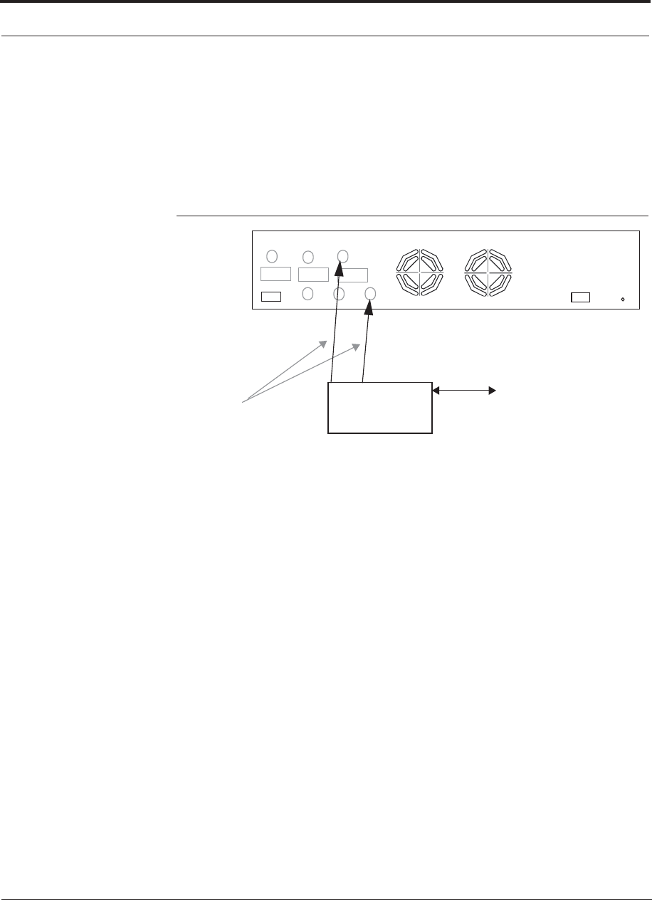
Interfacing the Fusion Wideband Main Hub to an RF Source
7-48 InterReach Fusion Wideband Installation, Operation, and Reference Manual
CONFIDENTIAL D-620616-0-20 Rev G
2. Connect the other end of the N-male to N-male coaxial cable to the DOWNLINK
connector on the Hub for the corresponding Band 1 or Band 2.
3. Connect an N-male to N-male coaxial cable to the receive simplex connector on
the base station.
4. Connect the other end of the N-male to N-male coaxial cable to the UPLINK con-
nector on the Hub for the corresponding Band 1 or Band 2.
Figure 7-27 Simplex Base Station to a Fusion Wideband Main Hub
N-male to N-male
Coaxial Cable
Base Station
Simplex T1/E1 to
Mobile
Switching
Center
Insert attenuator, if needed
Note: This applies to either Band 1, Band 2, and Band 3.
Band 1 Band 2 Band 3
UL1 UL2 UL3
DL1 DL2 DL3
AC Power
Alarms
Band 3
Connecting a Duplex Base Station to a Fusion Wideband Main Hub:
When connecting to a duplex base station, use a circulator or duplexer between it and
the Fusion Wideband Main Hub.
You can insert attenuators between the circulator or duplexer and Hub as needed.
1. Connect an N-male to N-male coaxial cable to the duplex connector on the base
station.
2. Connect the other N-male connector or duplexer to a circulator.
3. Connect an N-male to N-male coaxial cable to the DOWNLINK connector on the
Hub for Band 1, Band 2, and Band 3.
4. Connect the other end of the N-male coaxial cable to the transmit connector on the
circulator.
5. Connect an N-male to N-male coaxial cable to the UPLINK connector on the Hub
for Band 1, and Band 2, and Band 3.
6. Connect the other end of the N-male coaxial cable to the receive connector on the
circulator.
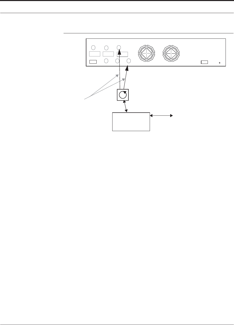
Help Hot Line (U.S. only): 1-800-530-9960 7-49
D-620616-0-20 Rev G CONFIDENTIAL
Interfacing the Fusion Wideband Main Hub to an RF Source
Figure 7-28 Duplex Base Station to a Fusion Wideband Main Hub
N-male to N-male
Coaxial Cable
Base Station
Duplex T1/E1 to
Mobile
Switching
Center
Insert attenuator, if needed N-male to N-male
Coaxial Cable
Note: This applies to either Band 1, Band 2, Band 3.
Band 1 Band 2 Band 3
UL1 UL2 UL3
DL1 DL2 DL3
AC Power
Alarms
Circulator
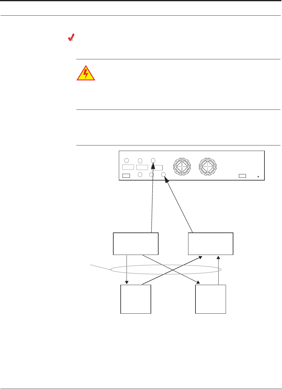
Interfacing the Fusion Wideband Main Hub to an RF Source
7-50 InterReach Fusion Wideband Installation, Operation, and Reference Manual
CONFIDENTIAL D-620616-0-20 Rev G
Connecting a Fusion Wideband Main Hub RF Band to Multiple
BTSs
WARNING: Only TE personnel or TE-authorized installation person-
nel should connect the Fusion Wideband Main Hub to a base station or
repeater. Exceeding the maximum input power could cause failure of
the Fusion Wideband Main Hub (refer to Section 5.2 on page 5-6 for
maximum power specifications). If the maximum composite power is
too high, attenuation is required.
You can use power combiner/splitters to connect a Fusion Wideband Main Hub RF
Band to multiple base stations, as shown in Figure 7-29.
Figure 7-29 Connecting a Fusion Wideband Main Hub to Multiple Base Stations
N-male to N-male
Coaxial Jumper Cables
between Combiner/Splitter and
Fusion Main Hub’s Downlink Port fo
r
N-male to N-male
Coaxial Jumper Cables
N-male to N-male
Coaxial Jumper Cable
to Repeater or
Base Station
between Combiner/Splitter and
Fusion Main Hub’s Uplink Port
2 x 1 Power
Combiner/Splitter 2 x 1 Power
Combiner/Splitter
BTS 1
UL DL
BTS 2
UL DL
Insert attenuators, if needed
for each on Band 1, Band 2, or Band 3 either Band 1, Band 2, or Band 3
Band 1 Band 2 Band 3
UL1 UL2 UL3
DL1 DL2 DL3
AC Power
Alarms
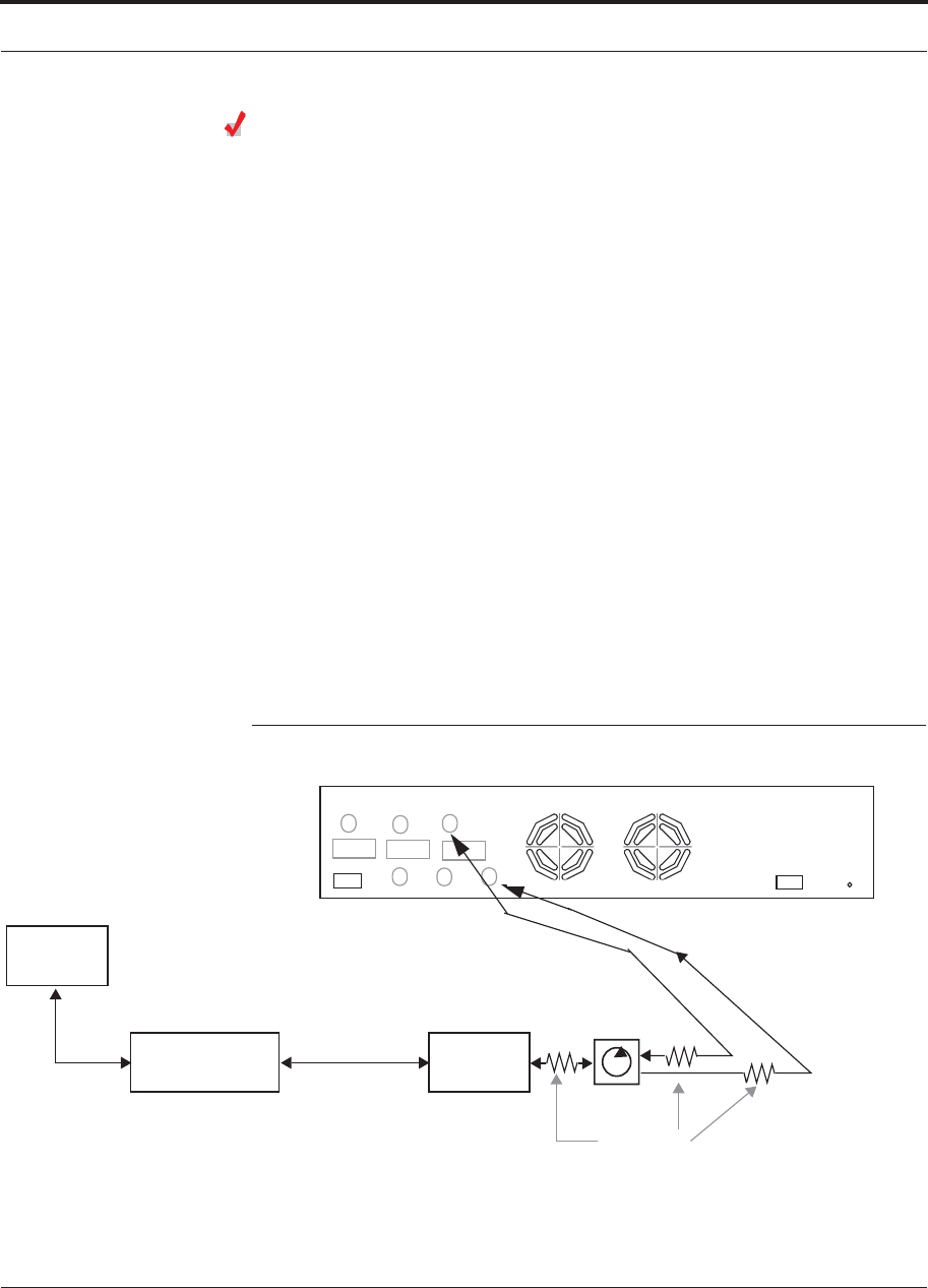
Help Hot Line (U.S. only): 1-800-530-9960 7-51
D-620616-0-20 Rev G CONFIDENTIAL
Interfacing the Fusion Wideband Main Hub to an RF Source
Connecting a Fusion Wideband Main Hub to a Roof-top Antenna
TE recommends that you use a lightning arrestor or surge protector in a roof-top
antenna configuration. Insert the lightning arrestor or surge protector between the
roof-top antenna and the repeater connected to the Fusion Wideband Main Hub RF
Band.
1. Connect an N-male to N-male coaxial cable to the roof-top antenna.
2. Connect the other end of the N-male to N-male coaxial cable to the grounded
surge suppressor.
3. Connect an N-male to N-male coaxial cable to the grounded surge suppressor.
4. Connect the other end of the N-male to N-male coaxial cable to the repeater.
5. Connect an N-male to N-male coaxial cable to the repeater.
6. Connect the other end of the N-male to N-male coaxial cable to the circulator
1 connector.
7. Connect an N-male to N-male coaxial cable to the circulator 2 connector.
8. Connect the other end of the N-male to N-male coaxial cable to the DOWNLINK
connector on the Hub for either Band 1 or Band 2.
Attenuation may be required to achieve the desired RF output at the RAU.
9. Connect an N-male to N-male coaxial cable to the circulator 3 connector.
10. Connect the other end of the N-male to N-male coaxial cable to the UPLINK con-
nector on the Hub for either Band 1 or Band 2.
Figure 7-30 Connecting a Fusion Wideband Main Hub to a Roof-top Antenna
Band 1 Band 2 Band 3
UL1 UL2 UL3
DL1 DL2 DL3
AC Power
Alarms
Roof-top
Antenna
Grounded
Surge Suppressor Repeater
N-male to N-male
Coaxial Cables
N-male to N-male
Coaxial Cable
N-male to N-male
Coaxial Cable Circulator
Attenuator
(optional)
Note: This applies to either Band 1 or Band 2.
12
3
Interfacing the Fusion Wideband Main Hub to an RF Source
7-52 InterReach Fusion Wideband Installation, Operation, and Reference Manual
CONFIDENTIAL D-620616-0-20 Rev G
Connecting a Fusion Wideband Main Hub to FlexWave Focus
Refer to the FlexWave Focus manual for information.
7.6.2 Connecting Multiple Fusion Wideband Main Hubs to an RF
Source
You can use power combiner/splitters as splitters to connect multiple Fusion Wide-
band Main Hubs in order to increase the total number of RAUs in a system. You can
also use power combiner/splitters to combine base station channels in order to
increase the number of RF carriers the system transports.
Connecting Multiple Fusion Wideband Main Hubs to a Simplex
Repeater or BTS
WARNING: Only TE personnel or TE-authorized installation person-
nel should connect the Fusion Wideband Main Hub to a base station or
repeater. Exceeding the maximum input power could cause failure of
the Fusion Wideband Main Hub (refer to Section 5.2 on page 5-6 for
maximum power specifications). If the maximum composite power is
too high, attenuation is required.
Considerations:
• 2 hybrid power combiner/splitters; one for uplink and one for downlink (2x1 for
two Fusion Wideband Main Hubs, 3x1 for three, 4x1 for four, and so on.)
• 1 N-male to N-male coaxial jumper cable between each power combiner/splitter
and the base station
• 2 N-male to N-male coaxial jumper cables between each power combiner/splitter
and each Fusion Wideband Main Hub RF Band (either Band 1, Band 2, or Band 3)
Procedure:
1. Connect the power combiner/splitters to the repeater or base station using N-male
to N-male coaxial jumper cables:
b. From the first power combiner/splitter to the repeater or base station UPLINK
c. From the second power combiner/splitter to the repeater or base station
DOWNLINK
4. Connect the power combiner/splitters to the Hubs:
a. From the first Hub’s UPLINK port (Band 1, Band 2, or Band 3) to the first
power combiner/splitter
b. From the first Hub’s DOWNLINK port (Band 1, Band 2, or Band 3 to the second
power combiner/splitter
c. From the second Hub’s UPLINK port (Band 1, Band 2, or Band 3) to the first
power combiner/splitter

Help Hot Line (U.S. only): 1-800-530-9960 7-53
D-620616-0-20 Rev G CONFIDENTIAL
Interfacing the Fusion Wideband Main Hub to an RF Source
d. From the second Hub’s DOWNLINK port (Band 1, Band 2, or Band 3) to the
second power combiner/splitter
NOTE: Connections should not cross Bands. For example, all Band 1 connections
should be made to the same hybrid power combiner/splitter connected to the repeater
BTS that matches the Band 1 frequency.
5. Check Hub LEDs.
After connecting and powering on the Hub, check all LEDs to ensure that the sys-
tem is operating properly.
Make sure the Hub is grounded. The warranty does not cover damage caused
when an ungrounded Hub is powered on.
NOTE: Use a 50 ohm terminator on any unused power combiner/splitter ports.
Figure 7-31 shows how to connect two Main Hubs to a simplex repeater or base sta-
tion. Connecting two Hubs increases the total number of supportable RAUs from 8 to
16.
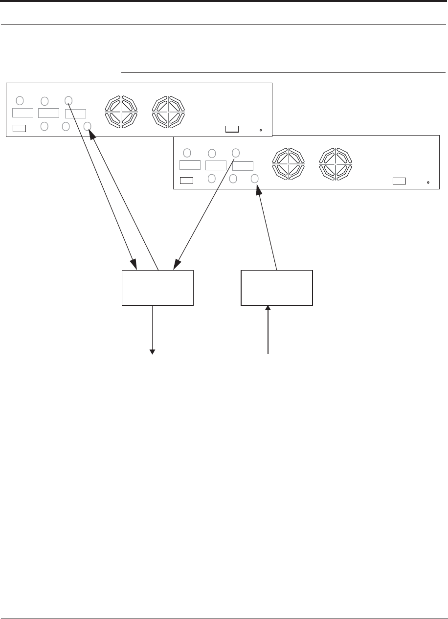
Interfacing the Fusion Wideband Main Hub to an RF Source
7-54 InterReach Fusion Wideband Installation, Operation, and Reference Manual
CONFIDENTIAL D-620616-0-20 Rev G
Figure 7-31 Connecting Two Fusion Wideband Main Hub’s RF Band Ports to a
Simplex Repeater or Base Station
N-male to N-male
Coaxial Jumper Cables
between Combiner/Splitter and
Fusion Main Hub’s Downlink Port for
Band 1 Band 2 Band 3
UL1 UL2 UL3
DL1 DL2 DL3
AC Power
Alarms
N-male to N-male
Coaxial Jumper Cable
to Repeater or
Base Station
2 x 1 Power
Combiner/Splitter
N-male to N-male
Coaxial Jumper Cable
to Repeater or
Base Station
2 x 1 Power
Combiner/Splitter
Band 1 Band 2 Band 3
UL1 UL2 UL3
DL1 DL2 DL3
AC Power
Alarms
N-male to N-male
Coaxial Jumper Cables
between Combiner/Splitter
and Fusion Main Hub’s Uplink
Port for either Band 1, Band 2,
or Band 3. either Band 1, Band 2, or Band 3.

Help Hot Line (U.S. only): 1-800-530-9960 7-55
D-620616-0-20 Rev G CONFIDENTIAL
Interfacing the Fusion Wideband Main Hub to an RF Source
Connecting Multiple Wideband Main Hubs to a Duplex Repeater
or BTS
WARNING: Only TE personnel or TE-authorized installation person-
nel should connect the Fusion Wideband Main Hub to a base station or
repeater. Exceeding the maximum input power could cause failure of
the Fusion Wideband Main Hub (refer to Section 5.2 on page 5-6 for
maximum power specifications). If the maximum composite power is
too high, attenuation is required.
Considerations:
• 2 hybrid power combiner/splitters; one for uplink and one for downlink (2x1 for
two Fusion Wideband Main Hubs, 3x1 for three, 4x1 for four, and so.)
• 2 N-male to N-male coaxial jumper cables to connect each Fusion Wideband Main
Hub’s RF Band to the power combiner/splitters
• 1 circulator
• 1 N-male to N-male coaxial jumper cable between each circulator and the repeater
or base station
• 1 N-male to N-male coaxial jumper cable between each circulator and power com-
biner/splitter
Procedure:
1. Connect the circulator to the repeater or base station using one N-male to N-male
coaxial jumper cable.
2. Connect each power combiner/splitter to the circulator using one N-male to
N-male coaxial jumper cable per combiner/splitter.
3. Connect the power combiner/splitter to the Hubs using N-male to N-male coaxial
jumper cable:
a. From the first Hub’s UPLINK (Band 1, Band 2, or Band 3) port to the first
power combiner/splitter
b. From the first Hub’s DOWNLINK (Band 1, Band 2, or Band 3) port to the sec-
ond power combiner/splitter
c. From the second Hub’s UPLINK (Band 1, Band 2, or Band 3) port to the first
power combiner/splitter
d. From the second Hub’s DOWNLINK (Band 1, Band 2, or Band 3) port to the
second power combiner/splitter

Interfacing the Fusion Wideband Main Hub to an RF Source
7-56 InterReach Fusion Wideband Installation, Operation, and Reference Manual
CONFIDENTIAL D-620616-0-20 Rev G
NOTE: Connections should not cross Bands. For example, all Band 1 connections
should be made to the same hybrid power combiner/splitter connected to the repeater
BTS that matches the Band 1 frequency.
5. Check Hub LEDs.
After connecting and powering on the Hub, check all LEDs to ensure that the sys-
tem is operating properly.
Make sure the Main Hub is grounded. The warranty does not cover damage
caused when an ungrounded Hub is powered on.
NOTE: Use a 50 ohm terminator on any unused power combiner/splitter ports.
Figure 7-32 shows how to connect two Hubs to a duplex repeater or base station. You
need to use one circulator and one more coaxial jumper cable, as shown.
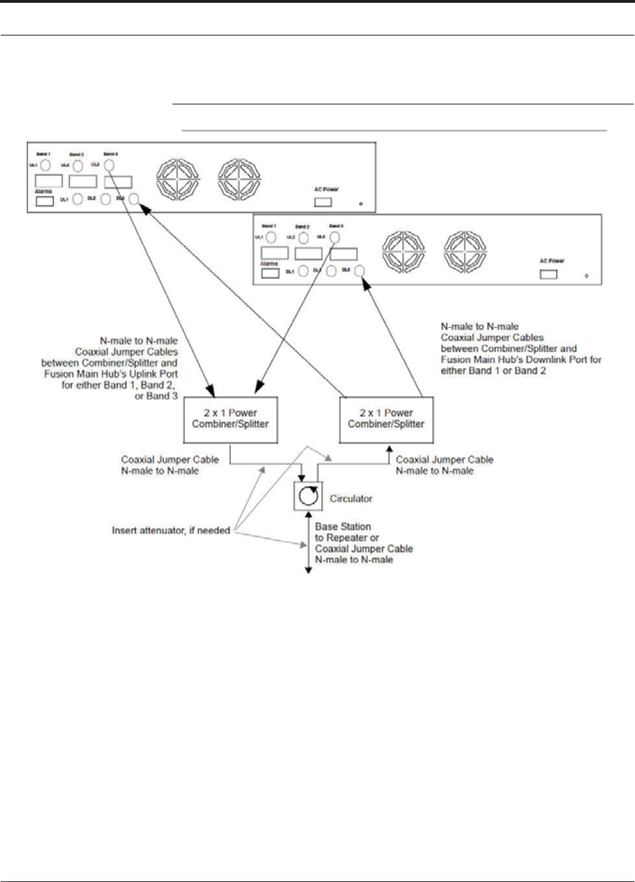
Help Hot Line (U.S. only): 1-800-530-9960 7-57
D-620616-0-20 Rev G CONFIDENTIAL
Interfacing the Fusion Wideband Main Hub to an RF Source
Figure 7-32 Connecting Two Fusion Wideband Main Hub’s RF Band Ports to a
Duplex Repeater or Base Station

Connecting Contact Alarms to a Fusion Wideband System
7-58 InterReach Fusion Wideband Installation, Operation, and Reference Manual
CONFIDENTIAL D-620616-0-20 Rev G
7.7 Connecting Contact Alarms to a Fusion Wideband
System
The Fusion Wideband Main Hub can generate (source) two contact alarms as well as
sense three external contact alarm.
• Alarm Source (refer to Section 7.7.1 on page 7-59)
The Fusion Wideband Main Hub has two alarm contacts, fault (major) and warn-
ing (minor). These contacts are normally-closed (NC) and will open when an inter-
nal alarm is detected.
NOTE: The contact can be changed to normally-open (NO) with Admin-
Browser. This is not recommended since no alarm would be sent if power to
the Fusion Wideband Main Hub fails.
• Fault is activated when any faults or disconnects are detected.
• Warning is activated when any warning conditions are detected
except lockout or when the end-to-end system test is not valid.
• Alarm Sense (refer to Section 7.7.2 on page 7-62)
The Fusion Wideband Main Hub can monitor 3 external alarm contacts. Each port
can be configured for normally-open (NO) or normally-closed (NC) contacts. The
interface expects a set of floating contacts, and an external voltage source is not
required for this interface. Use AdminBrowser to monitor the port status.
Table 7-8 lists the alarm types, equipment to which the Fusion Wideband Main Hub
is connected, cable(s) used, and the faults and warnings that are detected.
Table 7-8 Alarm Types
Alarm
Type
Fusion
Wideband
Connected to Cable(s) Used Errors Detected
Source FlexWave 5-port Alarm Daisy-Chain Cable Faults
Source BTS 5-port Alarm Daisy-Chain Cable Faults and Warnings
In addition, a custom daisy-chain cable-to-BTS interface
cable is required. Make this interface cable to the desired
length and with the appropriate pin placement.
Sense Unison 5-port Alarm Daisy-Chain Cable
and the Alarm Sense Adapter
Cable
Faults
Note that FlexWave Focus supports only faults (major errors).
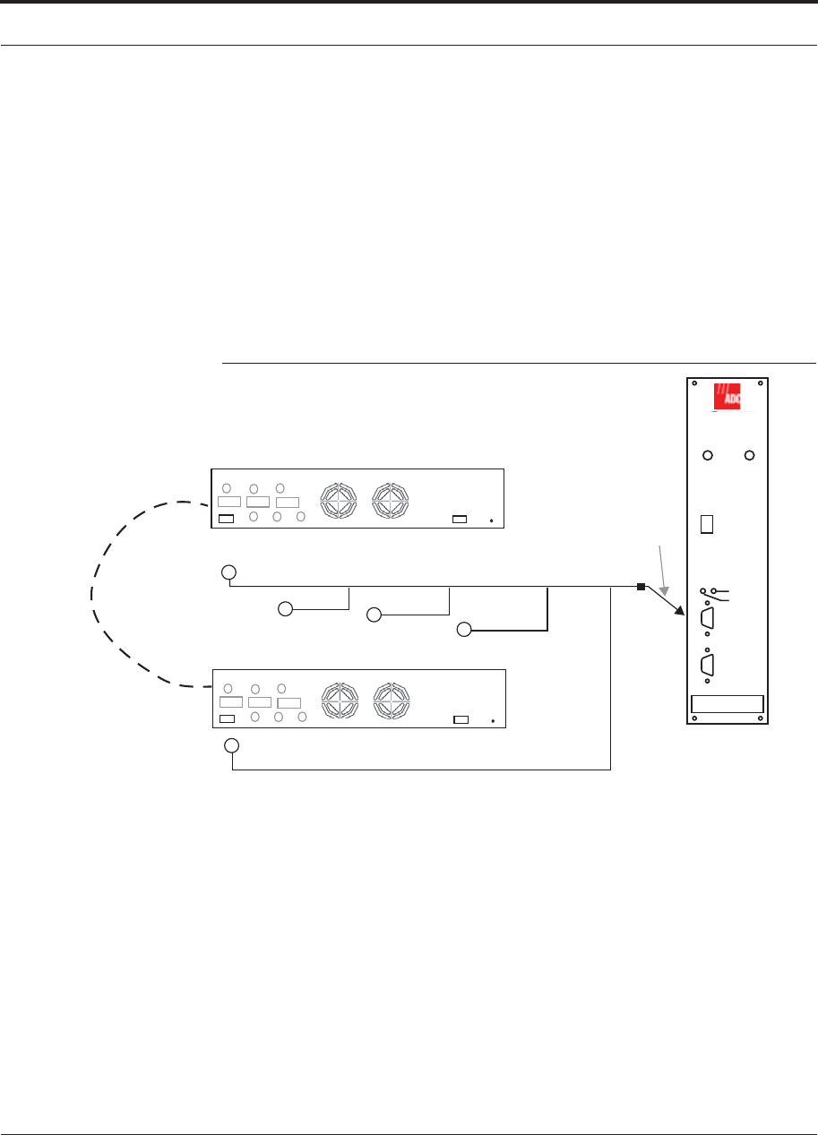
Help Hot Line (U.S. only): 1-800-530-9960 7-59
D-620616-0-20 Rev G CONFIDENTIAL
Connecting Contact Alarms to a Fusion Wideband System
7.7.1 Alarm Source
Fusion Wideband always acts as an alarm source, no matter what type of equipment
you are connecting to. Refer to Section 7.7.2 on page 7-62 if you want Fusion Wide-
band to sense Unison contact closures or other external alarms.
Using FlexWave Focus to Monitor Fusion Wideband
When you connect FlexWave Focus to the Fusion Wideband, the Fusion Wideband
Main Hub is the output of the alarms (alarm source) and Focus is the input (alarm
sense), as shown in Figure 7-33. Focus supports only faults (major errors).
Figure 7-33 Connecting FlexWave to Fusion Wideband
RF OUT
DOWNLINK RF IN
UPLINK
FIBER
UPLINK
DOWNLINK
ALARM
RS-232C
FlexWave
Focus
RFM
Alarm
Sense
Alarm
Source
Alarm
Source
5-port Alarm Daisy-Chain Cable
May need
9-pin Adapter,
which ships
with the cable
Fusion Main Hub
Band 1 Band 2 Band 3
UL1 UL2 UL3
DL1 DL2 DL3
AC Power
Alarms
Band 1 Band 2 Band 3
UL1 UL2 UL3
DL1 DL2 DL3
AC Power
Alarms
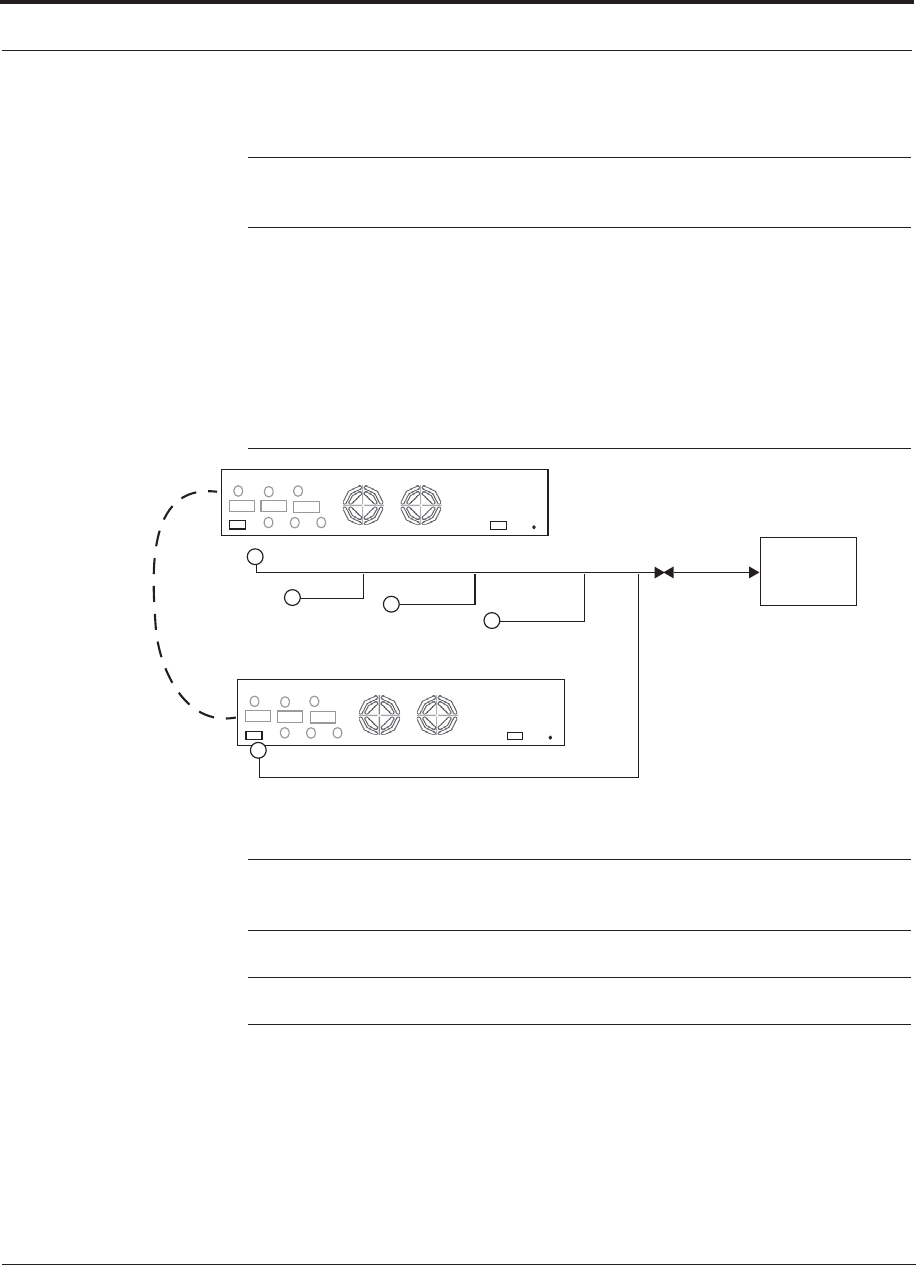
Connecting Contact Alarms to a Fusion Wideband System
7-60 InterReach Fusion Wideband Installation, Operation, and Reference Manual
CONFIDENTIAL D-620616-0-20 Rev G
Using a Base Station to Monitor Fusion Wideband
NOTE: The BTS must be configured, by the carrier, for contact closure monitoring
prior to connecting a Fusion Wideband Main Hub to it.
When you connect a BTS to Fusion Wideband, the Fusion Wideband Main Hub is the
output of the alarms (alarm source) and the BTS is the input (alarm sense), as shown
in Figure 7-34. An interface cable is required between the daisy-chain cable and the
BTS. Because BTS alarm interface pinouts and Fusion Wideband-to-BTS distances
vary, this cable is often custom and wired on-site. Refer to Section 3.2.1 for Alarm
Contact details (Normally Closed).
Figure 7-34 Using a BTS to Monitor Fusion Wideband
(custom made, on-site)
Band 1 Band 2 Band 3
UL1 UL2 UL3
DL1 DL2 DL3
AC Power
Alarms
Band 1 Band 2 Band 3
UL1 UL2 UL3
DL1 DL2 DL3
AC Power
Alarms
BTS
Interface
Cable
Alarm
Sense
Alarm
Source
Alarm
Source
5-port Alarm Daisy-Chain Cable
NOTE: For normally open contacts, the fault and warning contacts need to
be wired in parallel with other Main Hubs.
NOTE: TE does not recommend using normally open contacts.
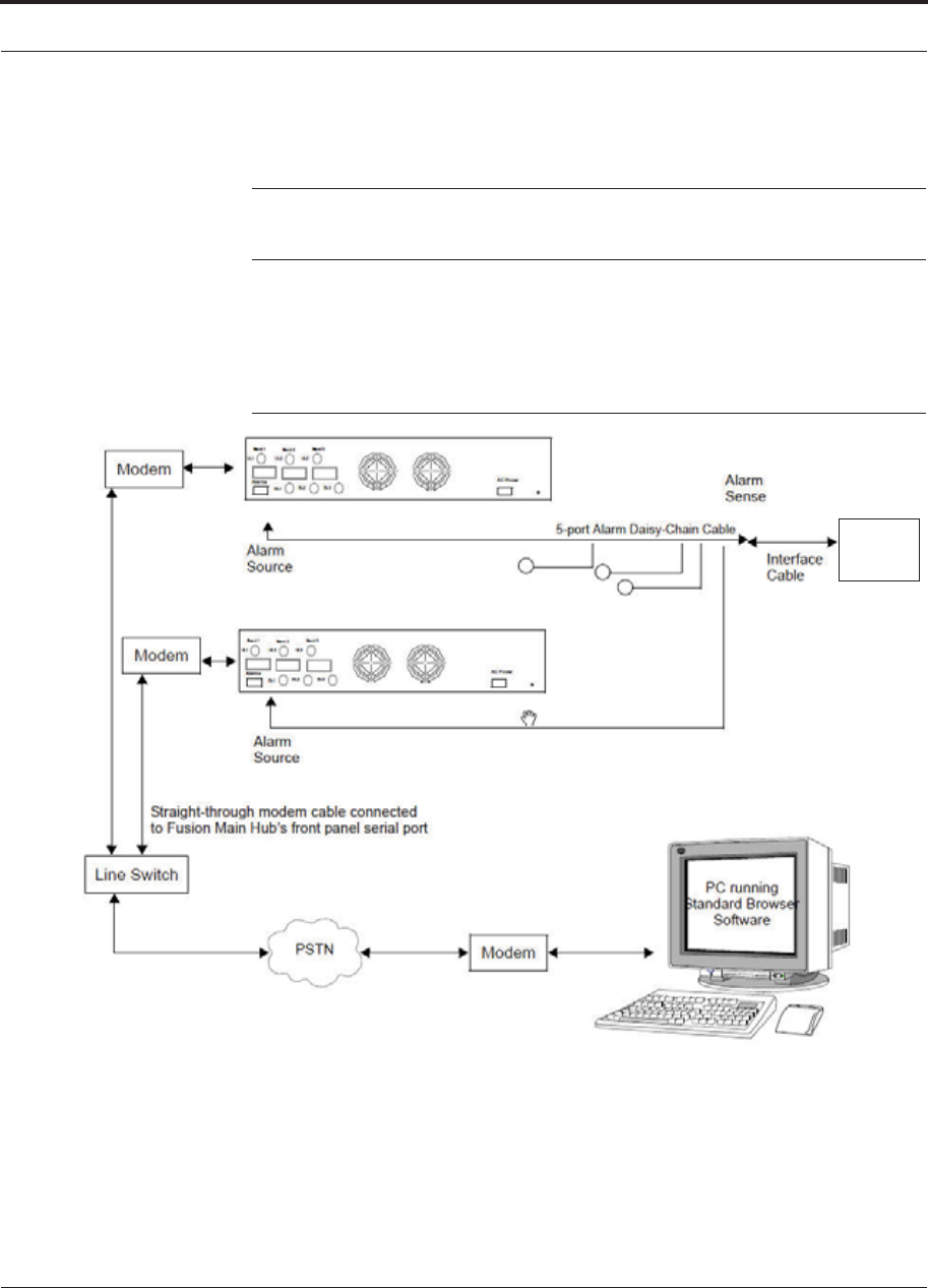
Help Hot Line (U.S. only): 1-800-530-9960 7-61
D-620616-0-20 Rev G CONFIDENTIAL
Connecting Contact Alarms to a Fusion Wideband System
Using a Base Station and AdminBrowser to Monitor Fusion
Wideband
NOTE: The BTS must be configured, by the carrier, for contact closure monitoring
prior to connecting a Fusion Wideband Main Hub to it.
In order to take full advantage of Fusion Wideband’s OA&M capabilities you can use
TE’s AdminBrowser software in addition to a BTS to monitor the system, as shown
in Figure 7-35. Refer to Section 7.8.7 for SNMP optional feature capabilities.
Figure 7-35 Using a BTS and AdminBrowser to Monitor Fusion Wideband
BTS
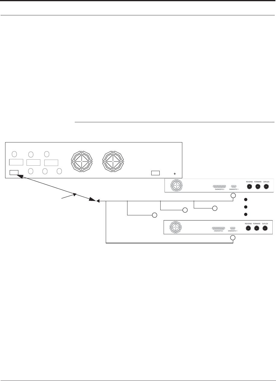
Connecting Contact Alarms to a Fusion Wideband System
7-62 InterReach Fusion Wideband Installation, Operation, and Reference Manual
CONFIDENTIAL D-620616-0-20 Rev G
7.7.2 Alarm Sense
Use AdminBrowser to enable the Fusion Wideband system for “alarm sense” when
connecting to the contact closure of Unison Main Hubs or other external alarms (refer
to Set Contact Sense Properties in the AdminBrowser User Manual).
Using Fusion Wideband to Monitor Unison
When you connect Unison to Fusion Wideband, the Fusion Wideband Main Hub is
the input of the alarms (alarm sense) and the Unison is the output (alarm source), as
shown in Figure 7-36. The input alarm sense needs to be set to normally closed (NC).
Figure 7-36 Using Fusion Wideband to Monitor Unison
Up to 5 Unison Main Hubs
Fusion Wideband Main Hub
Alarm
Source
Alarm
Sense Alarm
Source
Alarm Sense
Adapter Cable
5-port Alarm Daisy-Chain Cable
Band 1 Band 2 Band 3
UL1 UL2 UL3
DL1 DL2 DL3
AC Power
Alarms
Unison supports only faults. You must use the Alarm Sense Adapter Cable to inter-
face the daisy-chain cable to Fusion Wideband. The adapter cable is required because
it translates the Unison fault pinout to the sense input pins on the Fusion Wideband
Main Hub.

Help Hot Line (U.S. only): 1-800-530-9960 7-63
D-620616-0-20 Rev G CONFIDENTIAL
Connecting Contact Alarms to a Fusion Wideband System
Figure 7-37 Alarm Sense Contacts
8
1
Diagnostic I
External
Equipment
Contacts
+5V

Connecting Contact Alarms to a Fusion Wideband System
7-64 InterReach Fusion Wideband Installation, Operation, and Reference Manual
CONFIDENTIAL D-620616-0-20 Rev G
7.7.3 Alarm Cables
5-port Alarm Daisy-Chain Cable
Figure 7-38 shows the 5-port Alarm Daisy-Chain Cable (PN 4024-3), which supports
fault and warning conditions.
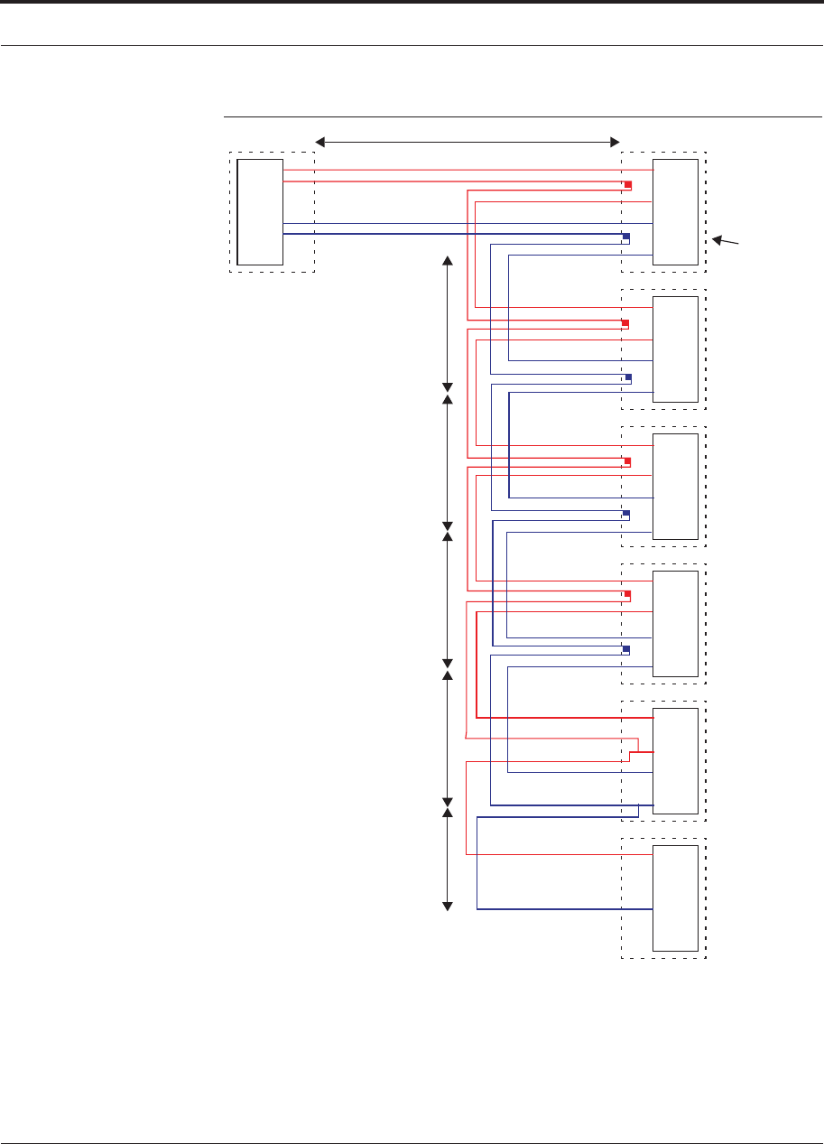
Help Hot Line (U.S. only): 1-800-530-9960 7-65
D-620616-0-20 Rev G CONFIDENTIAL
Connecting Contact Alarms to a Fusion Wideband System
Figure 7-38 5-port Alarm Daisy-Chain Cable
DB-9 female to
Base Station,
FlexWave Focus,
or J1
Female J2
Male
J3
Male
J4
Male
J5
Male
J6
Male
J7
Female
Terminator
Splice
Splice
Splice
Splice
Splice
Splice
Splice
Splice
7
9
4
5
7
9
4
5
7
9
4
5
7
9
4
5
7
9
4
5
7
4
1.2 meters (4 feet)
.5 meter
(1.5 feet)
DB-9 male to Fusion,
Unison, FlexWave
Focus, Alarm Port
DB-9 male to Fusion,
Unison, FlexWave
Focus Alarm Port
DB-9 male to Fusion,
Unison, FlexWave
Focus Alarm Port
DB-9 male to Fusion,
Unison, FlexWave
Focus Alarm Port
Option 1: DB-9 to Fusion,
Unison, FlexWave
Focus
Alarm Port.
J7 not used
Option 2: Use J2-J5
for alarm ports. J6 is used
to connect to an additional
Alarm Daisy-Chain Cable.
J7 is not used.
Option 3: Connect
fewer than 5 ports and
terminate the daisy chain
by connecting J7 to the
lowest unused port.
Connector
Hood
.5 meter
(1.5 feet)
.5 meter
(1.5 feet)
.5 meter
(1.5 feet)
.25 meter
(.75 feet)
the Alarm Sense
Adapter Cable when
connecting Unison
NOTE: Do not daisy-chain Fusion
Wideband Main Hubs with FlexWave
Focus if you want both faults and
warnings from Fusion. Only faults are
reported if you combine Fusion with
FlexWave in the same daisy chain.
7
9
4
5
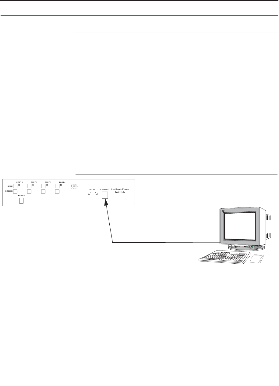
Alarm Monitoring Connectivity Options
7-66 InterReach Fusion Wideband Installation, Operation, and Reference Manual
CONFIDENTIAL D-620616-0-20 Rev G
7.8 Alarm Monitoring Connectivity Options
The following connectivity options are described:
• Section 7.8.1 Direct Connection . . . . . . . . . . . . . . . . . . . . . . . . . . . . . . . . . . . 7-66
• Section 7.8.2 Modem Connection . . . . . . . . . . . . . . . . . . . . . . . . . . . . . . . . . . 7-67
• Section 7.8.3 100 BASE-T Port Expander Connection . . . . . . . . . . . . . . . . . 7-76
• Section 7.8.4 POTS Line Sharing Switch Connection . . . . . . . . . . . . . . . . . . 7-77
• Section 7.8.6 Ethernet LAN Connection . . . . . . . . . . . . . . . . . . . . . . . . . . . . . 7-79
• Section 7.8.7 SNMP Interface . . . . . . . . . . . . . . . . . . . . . . . . . . . . . . . . . . . . . 7-80
7.8.1 Direct Connection
In this configuration, the PC connects directly to the RJ-45 100 BASE-T port on the
Fusion Wideband Main Hub’s front panel using an Ethernet cross-over cable.
Figure 7-39 OA&M Direct Connection
PC running
Software
Cross-over 100 BASE-T Cable
Standard Browser
AdminBrower is resident
in Fusion Wideband.
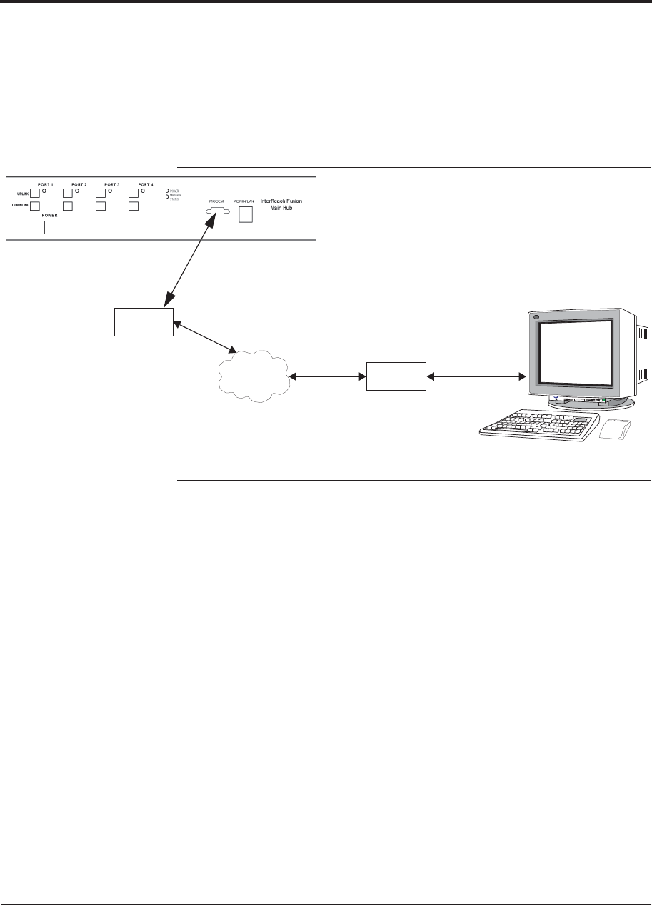
Help Hot Line (U.S. only): 1-800-530-9960 7-67
D-620616-0-20 Rev G CONFIDENTIAL
Alarm Monitoring Connectivity Options
7.8.2 Modem Connection
In this configuration, the PC and the Fusion Wideband Main Hub connect to analog
modems and communicate using a standard dial-up telephone connection.
Figure 7-40 OA&M Modem Connection
Straight-through
modem cable
PC running
Software
Standard Browser
Modem
Straight-through modem cable (#4028-10)
PSTN Modem
#140272-0
#4028-10
#140272-0
NOTE: Refer to Appendix A.3 on page A-7 for the modem cable wiring informa-
tion.
Modem switch settings are as follows for US Robotics modem:
• PC-side: 1, 2 and 6 Up
• Fusion Wideband Hub-side: 2 and 6 Up
7.8.2.1 Setting Up Fusion Wideband Modem (USR Modem) Using
AdminBrowser
Use the following steps to set up a PPP Dial-In on Fusion Wideband:
1. Start AdminBrowser as explained in the AdminBrowser manual.
2. Select System Configuration.
3. Select Setup Modem Connection. The window shown in Figure 7-41 appears.
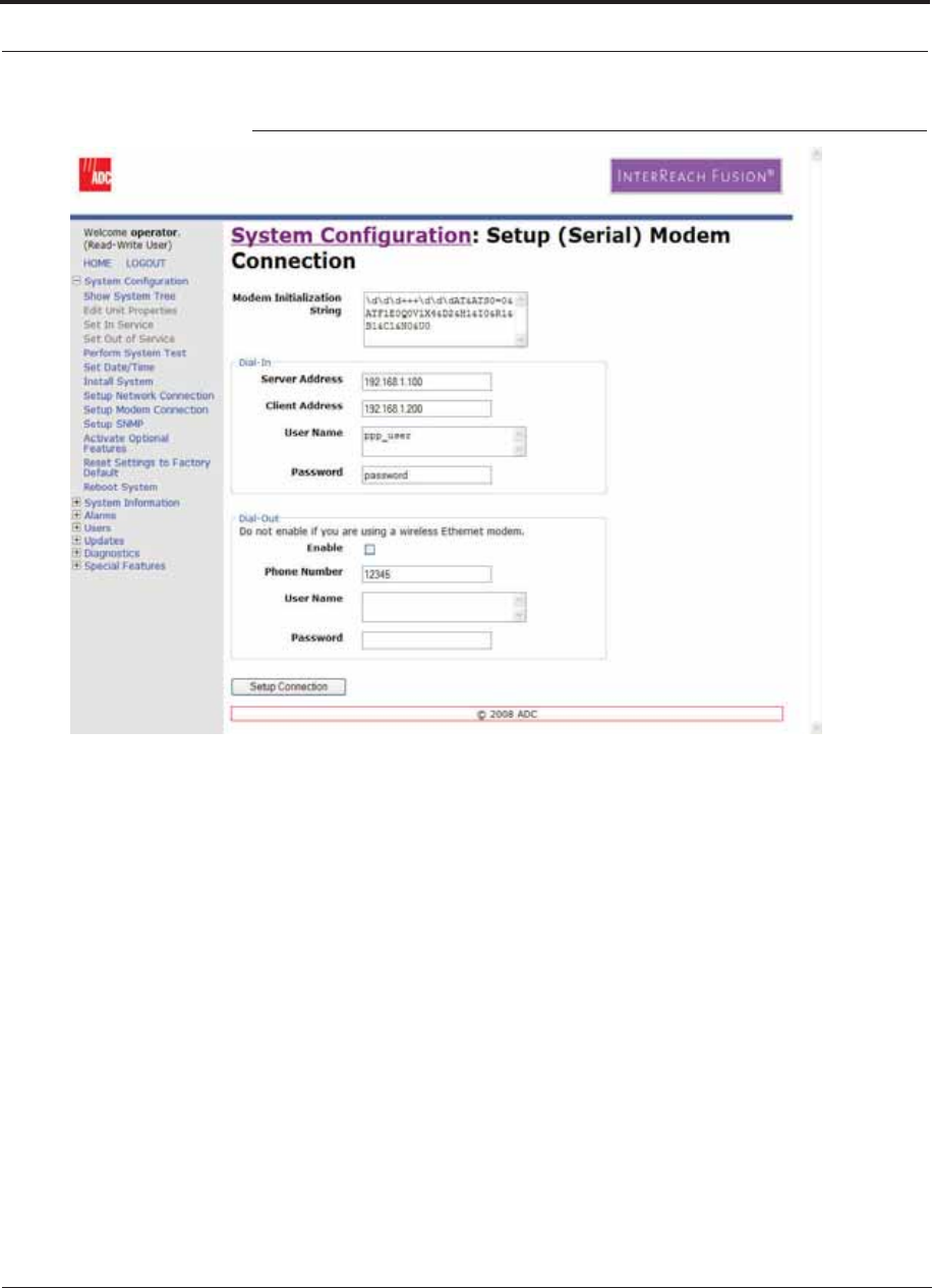
Alarm Monitoring Connectivity Options
7-68 InterReach Fusion Wideband Installation, Operation, and Reference Manual
CONFIDENTIAL D-620616-0-20 Rev G
Figure 7-41 Default Dial-in Settings (Fusion Wideband Hub)
4. Make sure the modem type is: “None”
• The Modem init string is for a USR modem.
• The server address is the IP address of the MH.
5. Click Setup Connection.
7.8.2.2 Setting Up a PC Modem Using Windows
Use the following sets to set up a dial-up connection on your PC:
1. Click Start, Settings, Network Connections. The window shown in Figure 7-42
appears.
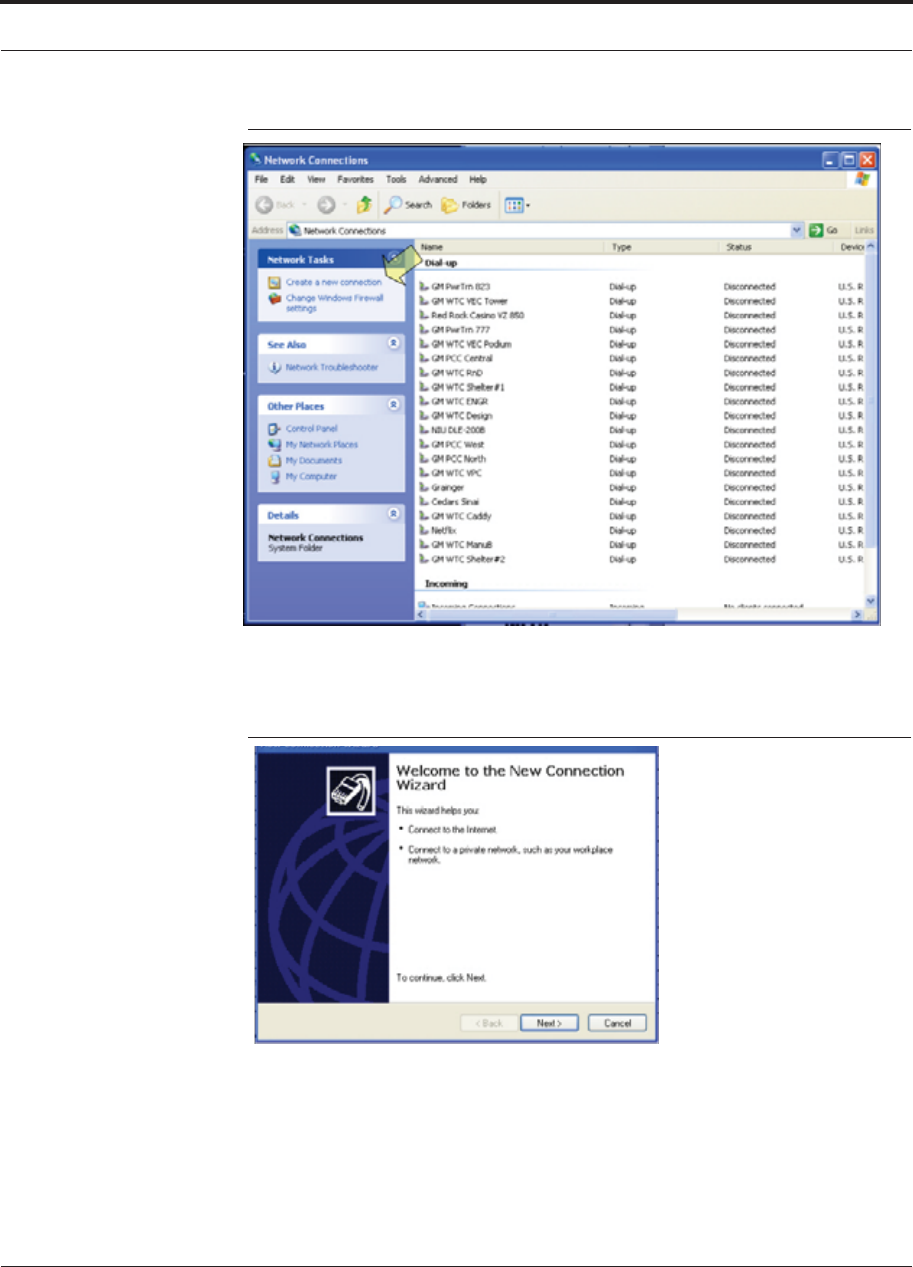
Help Hot Line (U.S. only): 1-800-530-9960 7-69
D-620616-0-20 Rev G CONFIDENTIAL
Alarm Monitoring Connectivity Options
Figure 7-42 Network Connections Window
2. Click Create a new connection. The window shown in Figure 7-43 appears.
Figure 7-43 New Connection Wizard - Welcome Window
3. Click Next. The window shown in Figure 7-44 appears.
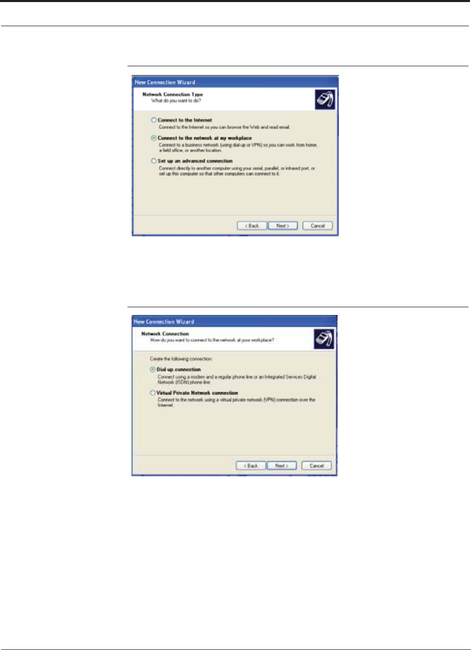
Alarm Monitoring Connectivity Options
7-70 InterReach Fusion Wideband Installation, Operation, and Reference Manual
CONFIDENTIAL D-620616-0-20 Rev G
Figure 7-44 New Connection Wizard - Network Connection Type Window
4. Select Connect to the network at my workplace and click Next. The window
shown in Figure 7-45 appears.
Figure 7-45 New Connection Wizard - Network Connection Window
5. Select Dial-up connection and click Next. The window shown in Figure 7-46
appears.
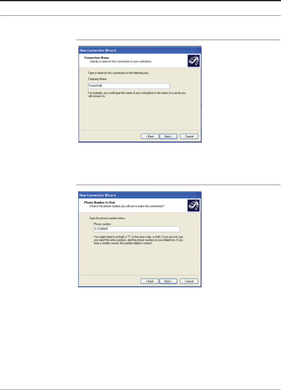
Help Hot Line (U.S. only): 1-800-530-9960 7-71
D-620616-0-20 Rev G CONFIDENTIAL
Alarm Monitoring Connectivity Options
Figure 7-46 New Connection Wizard - Connection Name Window
6. Type a name for this connection and click Next. The window shown in
Figure 7-47 appears.
Figure 7-47 New Connection Wizard - Phone Number to Dial Window
7. Type the desired dial in phone number and click Next. The window shown in
Figure 7-48 appears.
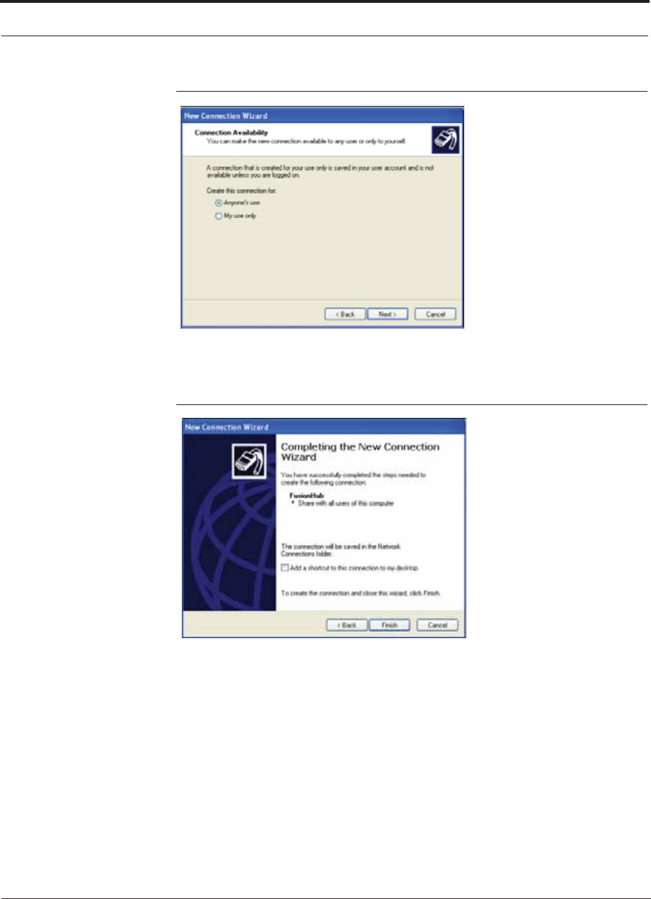
Alarm Monitoring Connectivity Options
7-72 InterReach Fusion Wideband Installation, Operation, and Reference Manual
CONFIDENTIAL D-620616-0-20 Rev G
Figure 7-48 New Connection Wizard - Connection Availability Window
8. Select Anyone’s use and click Next. The window shown in Figure 7-49 appears.
Figure 7-49 New Connection Wizard - Completing New Connection Window
9. Click Finish. The window shown in Figure 7-50 appears.
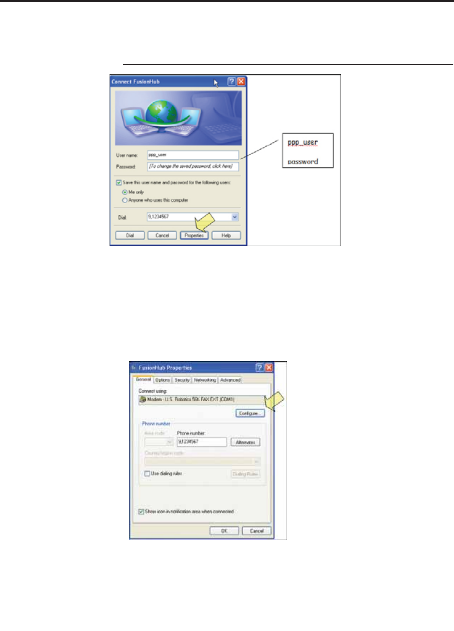
Help Hot Line (U.S. only): 1-800-530-9960 7-73
D-620616-0-20 Rev G CONFIDENTIAL
Alarm Monitoring Connectivity Options
Figure 7-50 Connect Fusion Wideband Hub Window
10. Type a password as indicated and click Properties. The window shown in
Figure 7-51 appears.
The default parameters are as follows:
• User name: ppp_user
• Password (one word, all lower case): password
Figure 7-51 Fusion Wideband Hub Properties Window
11. Click Configure... The window shown in Figure 7-52 appears.
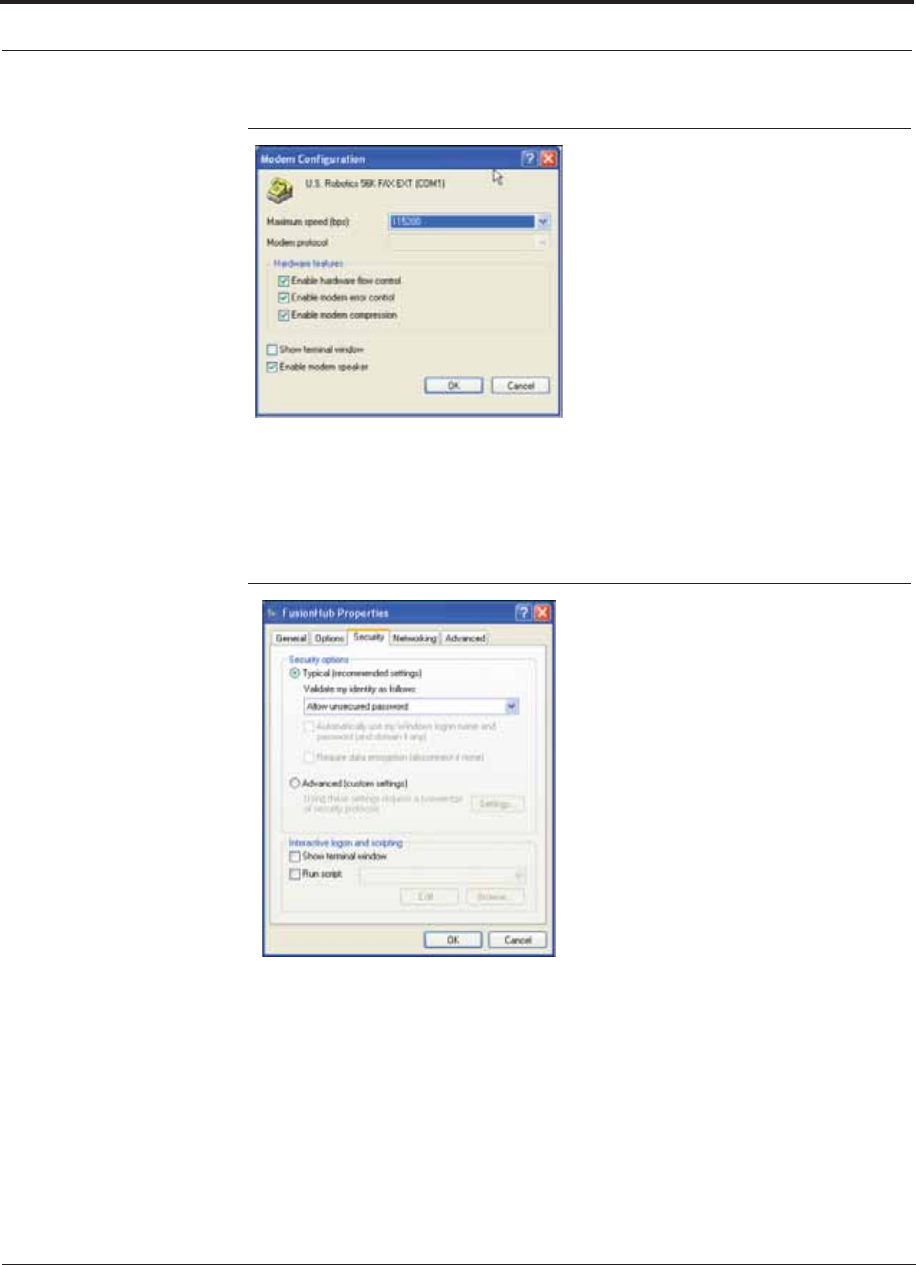
Alarm Monitoring Connectivity Options
7-74 InterReach Fusion Wideband Installation, Operation, and Reference Manual
CONFIDENTIAL D-620616-0-20 Rev G
Figure 7-52 Modem Configuration Window
12. Select the modem speed and other parameters for your modem as desired and
click OK.
13. Select the Security tab. The window shown in Figure 7-53 appears.
Figure 7-53 Fusion Wideband Hub Properties - Security Tab Window
14. Select Typical and then click the Networking tab. The window shown in
Figure 7-54 appears.
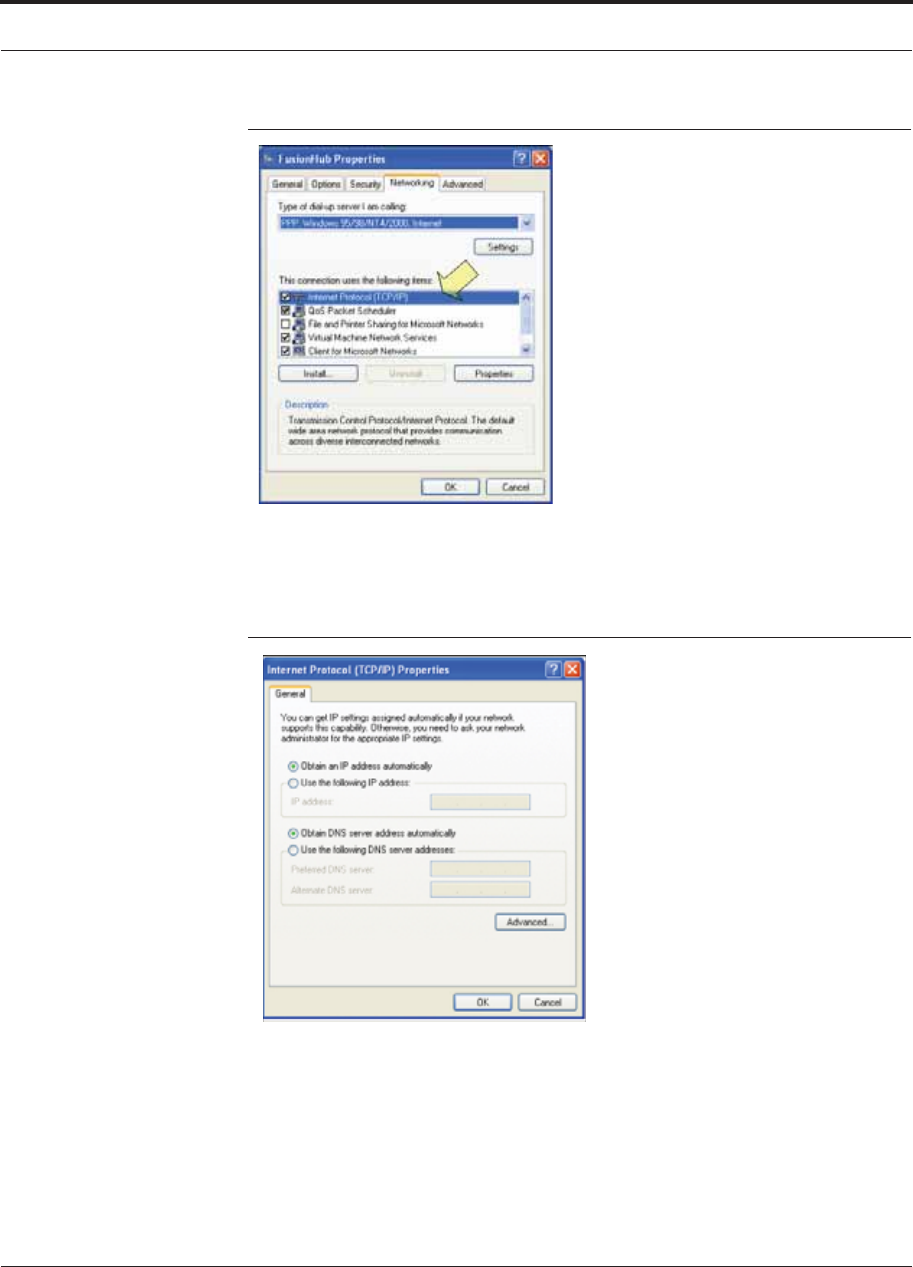
Help Hot Line (U.S. only): 1-800-530-9960 7-75
D-620616-0-20 Rev G CONFIDENTIAL
Alarm Monitoring Connectivity Options
Figure 7-54 Fusion Wideband Hub Properties - Networking Tab Window
15. Select Internet Protocol (TCP/IP) as shown and click Properties. The window
shown in Figure 7-55 appears.
Figure 7-55 Internet Protocol Properties Window
16. Select Obtain an IP address automatically and Obtain DNS server address
automatically and click OK.
17. To connect to the Fusion Wideband Hub over the Dial-up connection, start you
web browser and type the server IP address configured in Section 7.8.2.1 in the
address bar.
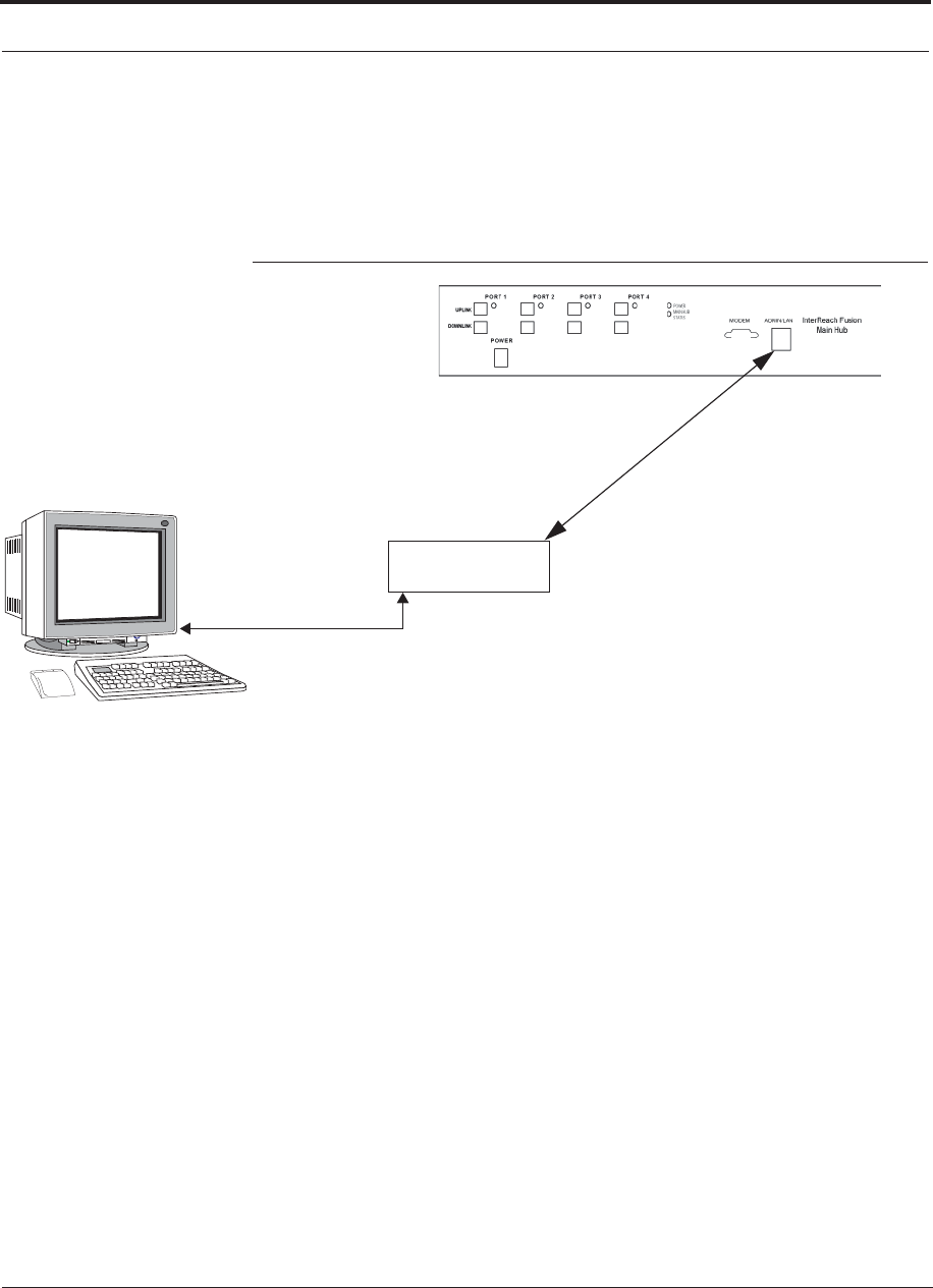
Alarm Monitoring Connectivity Options
7-76 InterReach Fusion Wideband Installation, Operation, and Reference Manual
CONFIDENTIAL D-620616-0-20 Rev G
7.8.3 100 BASE-T Port Expander Connection
In this configuration a LAN switch is used to allow the connection of multiple
devices to a single PC with a 100 BASE-T port. Testing was performed with a Link-
sys 4-port switch. Each Fusion Wideband MH must have a unique IP address.
Figure 7-56 OA&M Connection using a 232 Port Expander
LAN switch
100 BASE-T Ethernet connection
RJ-45 male to RJ-45 male
100 BASE-T Cable
PC running
Software
Standard Browser
AdminBrowser software is resident
in Fusion Wideband.
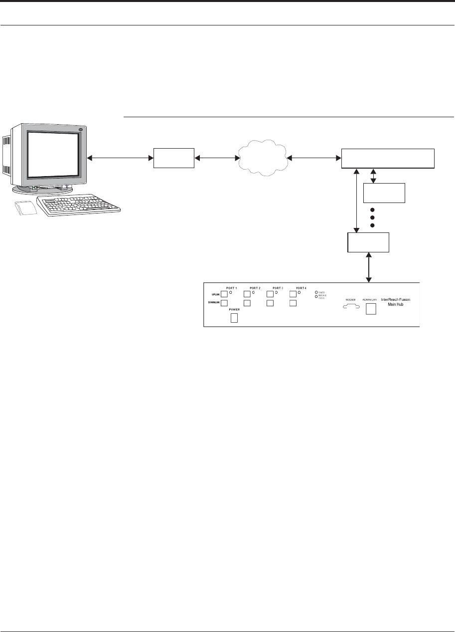
Help Hot Line (U.S. only): 1-800-530-9960 7-77
D-620616-0-20 Rev G CONFIDENTIAL
Alarm Monitoring Connectivity Options
7.8.4 POTS Line Sharing Switch Connection
Using a line sharing switch, you can connect two or more modems to a single tele-
phone line.
Figure 7-57 OA&M Connection Using a POTS Line Sharing Switch
Modem
PSTN
Line Sharing Switch
Up to 4 modems
per Switch
Modem
Modem
Straight-through
modem cable (#4028-10)
Straight-through
modem cable
PC running
Software
Standard Browser
Standard phone cable
#4028-10 #140272-0
4- or 8-port 4-port:
#240031-0
8-port
#240052-0
#140272-0
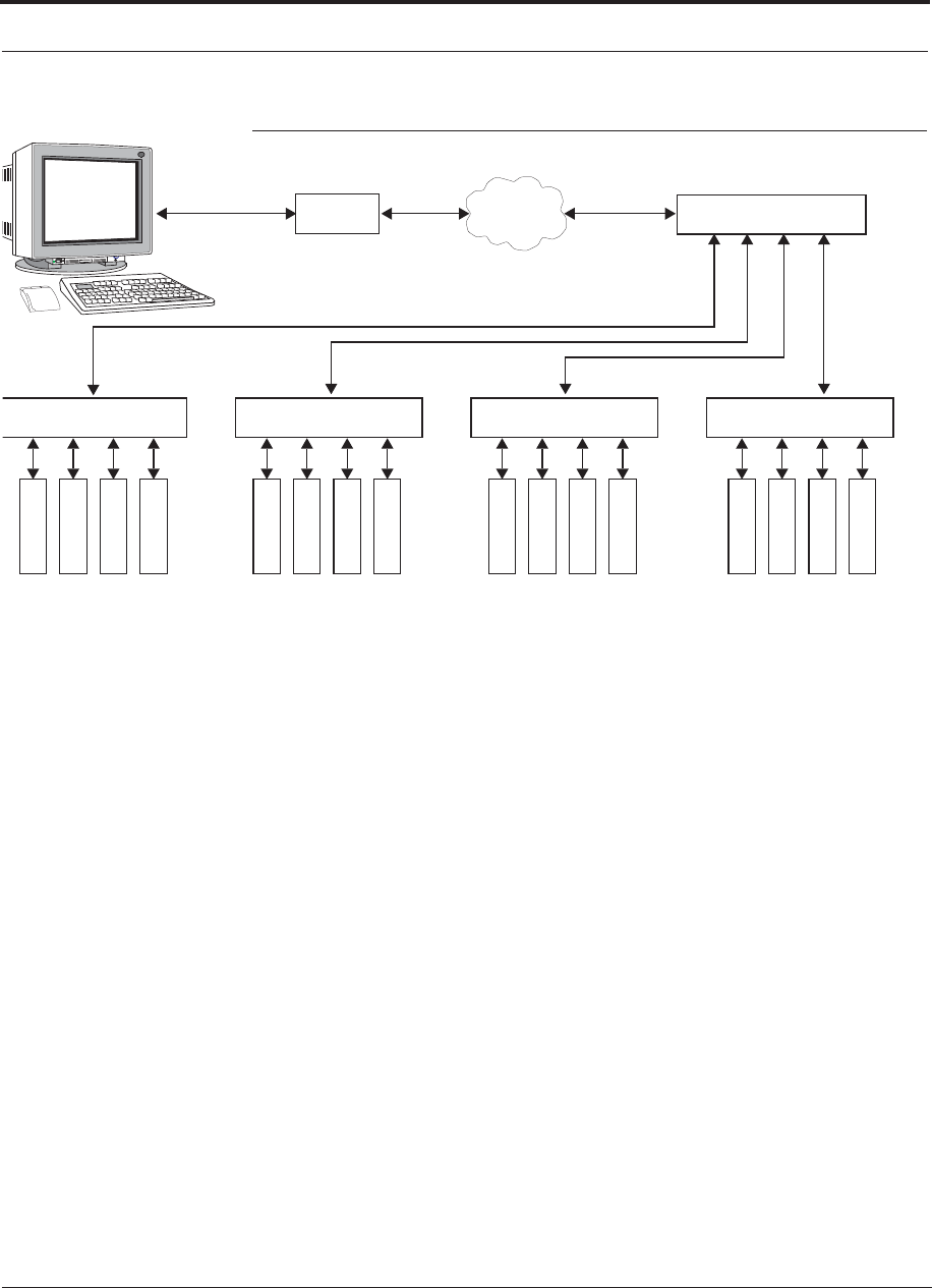
Alarm Monitoring Connectivity Options
7-78 InterReach Fusion Wideband Installation, Operation, and Reference Manual
CONFIDENTIAL D-620616-0-20 Rev G
Figure 7-58 Cascading Line Sharing Switches
Modem
PSTN
Line Sharing Switch
Line Sharing Switch Line Sharing Switch Line Sharing Switch Line Sharing Switch
M
o
d
e
m
M
o
d
e
m
M
o
d
e
m
M
o
d
e
m
M
o
d
e
m
M
o
d
e
m
M
o
d
e
m
M
o
d
e
m
M
o
d
e
m
M
o
d
e
m
M
o
d
e
m
M
o
d
e
m
M
o
d
e
m
M
o
d
e
m
M
o
d
e
m
M
o
d
e
m
Straight-through
modem cable
Straight-
through
modem
cables
PC running
Software
Standard Browser
Standard phone cable
4-port: #240031-0
8-port: #240052-0
4-port:
#240031-0
8-port:
#240052-0
7.8.5 Ethernet RF Modem
Fusion Wideband can also use an Ethernet-based RF modem. Just about any RF
modem will work, although modems that support Port Address Translation are best.
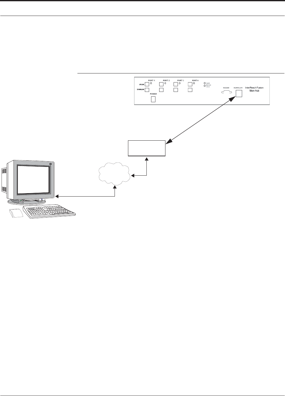
Help Hot Line (U.S. only): 1-800-530-9960 7-79
D-620616-0-20 Rev G CONFIDENTIAL
Alarm Monitoring Connectivity Options
7.8.6 Ethernet LAN Connection
An Ethernet LAN connection can be used to communicate between the PC and
Fusion Wideband. Testing was performed with an Linksys 4-port LAN switch.
Figure 7-59 OA&M Connection Using Ethernet and ENET/232 Serial Hub
LAN
Switch
TCP/IP
Ethernet
100 BASE-T Cable
RJ-45 to RJ-45 male
Ethernet
PC running
Software
Standard Browser
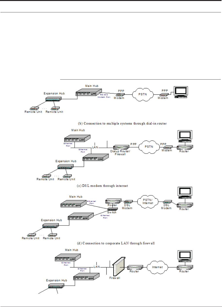
Alarm Monitoring Connectivity Options
7-80 InterReach Fusion Wideband Installation, Operation, and Reference Manual
CONFIDENTIAL D-620616-0-20 Rev G
7.8.7 SNMP Interface
Faults and warnings can also be diagnosed with SNMP using a standard (NMS) net-
work management system (optional). SNMP resident software in Fusion Wideband
provides SNMP interactions for Traps and Notification.
The Fusion Wideband SNMP includes a MIB for integrating into the Network Man-
agement System (NMS) and supports SNMPv1 and SNMPv2c.
Figure 7-60 Fusion Wideband SNMP Configuration Options

InterReach Fusion Wideband Installation, Operation, and Reference Manual 8-1
D-620616-0-20 Rev G CONFIDENTIAL
SECTION 8 Replacing Fusion Wideband
Components
This section contains the following subsections:
• Section 8.1 Replacing an RAU 8-1
• Section 8.2 Replacing a Fusion Wideband Expansion Hub . . . . . . . . . . . . . . 8-3
• Section 8.3 Replacing a Fusion Wideband Main Hub . . . . . . . . . . . . . . . . . . . 8-4
8.1 Replacing an RAU
Be aware that the new RAU must support the same bands as the one you are replac-
ing. If the RAU is of the wrong band combination, it will not operate properly in the
system.
Replacing an RAU
1. Using AdminBrowser, log in and click SYSTEM INFORMATION.
2. Click SHOW SYSTEM TREE, select Fusion Wideband Main Hub, and click GET SYS-
TEM INFORMATION.
All system settings for Hubs and RAUs will be displayed. Write down or save the
Uplink and Downlink Attenuation setting so you can set the new RAU with the
same settings.
3. Click CANCEL to close the window.
4. Verify that the new RAU is of the same frequency bands as the one replaced.
5. Disconnect the CATV cable and antenna cable from the unit to be replaced.
6. Install the new RAU.
7. Connect the antenna cable and then the CATV cable to the new RAU.
8. Click SYSTEM CONFIGURATION.
9. Click SHOW SYSTEM TREE.
10. Select the Fusion Wideband RAU replaced and click EDIT UNIT PROPERTIES.

Replacing an RAU
8-2 InterReach Fusion Wideband Installation, Operation, and Reference Manual
CONFIDENTIAL D-620616-0-20 Rev G
11. Set the attenuation of each band as the old RAU was programmed and click SAVE
PROPERTIES.
Perform System Test
When convenient, perform System Test to optimize performance.
During System Test, the entire system is temporarily off-line and no RF is
being transmitted.
Checking the RAU’s LEDs
1. The RAU’s LINK and ALARM LEDs should blink (green/red) on power up.
• If the LEDs do not blink on power up, replace the RAU.
2. After several seconds both LEDs should change to green, which indicates that the
unit has been successfully replaced, there is communication with the Hub, and the
RAU band is correct.
a. If the LINK LED remains green and the ALARM LED remains red, verify that
the RAU model is correct for the intended frequency band.
– Disconnect the cable and then reconnect it once; doing this more than once
will not change the result.
b. If both LEDs still don’t change to green, use AdminBrowser to determine the
exact nature of the fault and see a recommendation of how to correct it.
c. If both LEDs turn red (after 90 seconds), the Hub has terminated communica-
tions.

Help Hot Line (U.S. only): 1-800-530-9960 8-3
D-620616-0-20 Rev G CONFIDENTIAL
Replacing a Fusion Wideband Expansion Hub
8.2 Replacing a Fusion Wideband Expansion Hub
Replacing a Fusion Wideband Expansion Hub
1. Turn off the power to the Expansion Hub.
2. Disconnect all CATV cables, both fiber cables, and the AC power cord.
3. Replace the Expansion Hub with a new one.
4. Connect the AC power cord, all CATV cables, and both fiber cables – remember-
ing to clean and correctly connect the uplink and downlink fiber.
5. Turn on the power to the Expansion Hub.
AdminBrowser Tasks
• The Main Hub automatically issues the band setting.
• When convenient, use AdminBrowser to perform System Test in order to optimize
performance.
During System Test, the entire system is temporarily off-line and no RF is
being transmitted. For a fully loaded system (one Main Hub, four Expansion
Hubs, and 32 RAUs), it can take up to 1.5 minutes to complete the test.
Checking the Expansion Hub’s LEDs
• The LEDs should blink through all states on power up.
• If the LEDs do not blink on power up, replace the Expansion Hub.
• If the LEDs do not illuminate at all, make sure the AC power cable is con-
nected.
• The UL STATUS and DL STATUS LEDs should be green.
• The E-HUB STATUS and POWER LEDs should be green.
• For each CATV port that has an RAU connected the LEDs should be green.
It can take several seconds for each CATV connection for the LEDs to display
properly.
NOTE: Refer to Section 9 for troubleshooting using the LEDs.

Replacing a Fusion Wideband Main Hub
8-4 InterReach Fusion Wideband Installation, Operation, and Reference Manual
CONFIDENTIAL D-620616-0-20 Rev G
8.3 Replacing a Fusion Wideband Main Hub
You must record the system configuration settings from the old Fusion Wideband
Main Hub’s memory before replacing the unit. You will program the new Main Hub
with this information. If the Main Hub is programmed incorrectly, the system will not
work. If the Hub to be replaced is not functioning and you cannot use AdminBrowser,
get the configuration settings from the As-Built Document that was created as part of
the original installation.
Replacing a Fusion Wideband Main Hub
1. Using AdminBrowser, log in, click SYSTEM INFORMATION, click SHOW SYSTEM
TREE, select Fusion Wideband Hub, click GET SYSTEM INFORMATION.
2. Turn off the power to the Fusion Wideband Main Hub.
3. Disconnect all cables and the AC power cord.
4. Replace the Main Hub with a new one.
5. Connect the AC power cord and all cables.
6. Connect the crossover Ethernet cable to the PC and then to the Main Hub’s front
panel 100Base-T connector. ADMIN/LAN port)
7. Start the standard browser on the PC to communicate with AdminBrowser soft-
ware.
8. Turn on the power to the Main Hub.
9. Observe the LEDs after turning on the power.
All the LEDs blink during the initial power up sequence. All LEDs should turn
green after the power on sequence is complete. Power up sequence takes between
1 and 2 minutes depending on the number of RAUs.
Configure the New Fusion Wideband Main Hub
1. Using AdminBrowser and log in to the Main Hub.
2. Click SYSTEM CONFIGURATION.
3. Click SET DATE/TIME and enter the current date and time.
4. Click SET DATE/TIME.
5. Follow the instructions to eventually reboot the system to set the date and time.
6. Using AdminBrowser, log in and click SYSTEM CONFIGURATION.
7. Click INSTALL SYSTEM.
8. Set the new Main Hub parameters from the old Main Hub and click INSTALL SYS-
TEM (that is, uplink and downlink gain, system labels, and so on).
9. Follow the instructions to perform a System Test.

Help Hot Line (U.S. only): 1-800-530-9960 8-5
D-620616-0-20 Rev G CONFIDENTIAL
Replacing a Fusion Wideband Main Hub
10. Click SYSTEM CONFIGURATION and click on SETUP NETWORK CONNECTION OR
MODEM CONNECTION if the Main Hub has Network or Modem equipment con-
nected to it.
During System Test, the entire system is temporarily off-line and no RF is
being transmitted.
Checking the Main Hub’s LEDs
• The LEDs should blink through a 5-second test on power up.
• If the LEDs do not blink on power up, replace the Main Hub.
• If the LEDs do not illuminate at all, make sure the AC power cable is con-
nected.
• For each fiber optic port that has a connected Expansion Hub, which has been pro-
grammed with a band, the PORT LED should be green.
• Refer to Section 9.3, “Troubleshooting,” on page 9-3 for more LED states.
NOTE: If there is no communication between the Main Hub and the Expansion
Hubs, use the AdminBrowser to isolate system problems.

Replacing a Fusion Wideband Main Hub
8-6 InterReach Fusion Wideband Installation, Operation, and Reference Manual
CONFIDENTIAL D-620616-0-20 Rev G

InterReach Fusion Wideband Installation, Operation, and Reference Manual 9-1
D-620616-0-20 Rev G CONFIDENTIAL
SECTION 9 Maintenance, Troubleshooting,
and Technical Assistance
This section contains the following subsections:
• Section 9.1 Service . . . . . . . . . . . . . . . . . . . . . . . . . . . . . . . . . . . . . . . . . . . . . 9-1
• Section 9.2 Maintenance . . . . . . . . . . . . . . . . . . . . . . . . . . . . . . . . . . . . . . . . . 9-2
• Section 9.3 Troubleshooting . . . . . . . . . . . . . . . . . . . . . . . . . . . . . . . . . . . . . . 9-3
• Section 9.4 Troubleshooting CATV . . . . . . . . . . . . . . . . . . . . . . . . . . . . . . . 9-10
• Section 9.5 Technical Assistance . . . . . . . . . . . . . . . . . . . . . . . . . . . . . . . . . . 9-10
9.1 Service
There are no user-serviceable parts in any of the Fusion Wideband components.
Faulty or failed components are fully replaceable through TE. All units should be
replaced and returned to the factory for service if needed.
Address 541 E. Trimble Road
San Jose, California
95131-1224 USA
Technical Support 1-800-530-9960 (U.S. and Canada only)
+1-952-917-0761 (International)
Web Address http://www.te.com/WirelessSupport

Maintenance
9-2 InterReach Fusion Wideband Installation, Operation, and Reference Manual
CONFIDENTIAL D-620616-0-20 Rev G
9.2 Maintenance
Keep the fiber ports clean and free of dust. No other periodic maintenance of the
Fusion Wideband equipment is required.
To clean the fiber ports:
You can clean the Hub’s fiber ports using canned compressed air or isopropyl alcohol
and cotton swabs.
Considerations:
• If you use compressed air:
• The air must be free of dust, water, and oil.
• Hold the can level during use.
• If using isopropyl alcohol and foam-tipped swab:
• Use only 98% pure or more alcohol.
Procedure using compressed air:
1. Remove the connector’s dust cap.
2. Spray the compressed air away from the unit for a few seconds to clean out the
nozzle and then blow dust particles out of each fiber port.
Procedure using isopropyl alcohol:
1. Remove the connector’s dust cap.
2. Dip a 2.5mm lint-free, foam-tipped swab in isopropyl alcohol and slowly insert
the tip into the connector.
3. Gently twist the swab to clean the connector.
4. Insert a dry swab to dry the connector.
Additionally, you can use compressed air after the alcohol has completely evapo-
rated.

Help Hot Line (U.S. only): 1-800-530-9960 9-3
D-620616-0-20 Rev G CONFIDENTIAL
Troubleshooting
9.3 Troubleshooting
NOTE: Fusion Wideband has no user-serviceable parts. Faulty or failed
units are fully replaceable through TE.
Sources of potential problems include:
• Faulty cabling/connector
• Malfunction of one or more Fusion Wideband components
• Antenna, base station, or repeater problem
• External RF interface
• Tripped circuit breaker
• Equipment is not grounded
• Using an Ethernet crossover cable that does not support full hardware handshaking
when using AdminBrowser
NOTE: Faulty cabling is the cause of a vast majority of problems. All CATV 75
Ohm cable should be tested to TIA-570-B specifications. The RAU will be damaged
if the cable connector is not installed properly.
You must use AdminBrowser for troubleshooting the system, use the LEDs only as
backup or for confirmation.
If you cannot determine the cause of a problem after following the recommended pro-
cedures, call TE Customer Support:
1-800-530-9960 (U.S. and Canada only)
+1-952-917-0761 (International)
Or, email us at WirelessSupport@te.com.
Please provide the following information:
• Serial number of the unit
• Description of the problem
• Using AdminBrowser 1.00, access Special Features, then the Get Service
Information window. Save and email this file to TE.
• What is the length of the CATV cable? What type is it (for example RG-6)?
• Status of the LEDs on the unit
• Was the unit power cycled?

Troubleshooting
9-4 InterReach Fusion Wideband Installation, Operation, and Reference Manual
CONFIDENTIAL D-620616-0-20 Rev G
9.3.1 Troubleshooting Using AdminBrowser
Use AdminBrowser software to determine the current faults and warnings for all of
the units in the system. To troubleshoot, start with the Fusion Wideband Main Hub’s
faults AND warnings, then proceed to each of the Expansion Hubs, finishing with
each of the RAUs.
NOTE: AdminBrowser v1.00 displays events (faults, warnings, or status
messages) depending on your view preference. To change your view prefer-
ence, refer to Section 3.5.2, “View Preference,” on page 3-12.
System Troubleshooting
Using AdminBrowser, click SYSTEM INFORMATION, then click GET FAULTS, WARNINGS
AND STATUSES. This gives the present status of the system, depending upon View
Preferences for all components.
Faults usually impact service; warnings may impact service; status messages contain
information that should not be ignored, but indicate conditions that do not generally
impact service.
NOTE: System commands can take longer to execute compared to compo-
nent commands.
NOTE: This RAU icon indicates there is fault on the RAU. This icon
indicates a disconnected device. You cannot request status on a discon-
nected device.
9.3.1.1 Troubleshooting Recommendations
Some actions that you can take, depending on the device fault or warning include, are
as follows:
a. Hardware faults on Expansion Hub.
– Try swapping fiber with another Expansion Hub at the Main Hub.
– Try cleaning the fiber and the fiber ports with alcohol foam tip swab and
compressed air. See Section , “To clean the fiber ports:,” on page -2.
– Power cycle the Expansion Hub.

Help Hot Line (U.S. only): 1-800-530-9960 9-5
D-620616-0-20 Rev G CONFIDENTIAL
Troubleshooting
b. Under Alarms, click CLEAR ALL DISCONNECTS at the Fusion Wideband Main
Hub.
c. Power cycle the Fusion Wideband Main Hub.
d. RAU hardware faults. Try moving a working CATV to the suspect port and
verifying that the RAU comes up OK.
e. Try isolating the system components:
– Check to see if the whole system is effected or a portion of the system.
– If the whole system is effected, disconnect the DAS system from the RF
source and see if the RF source is working.
– Continue to isolate by disabling portions of the system. Under System Con-
figuration, click SHOW SYSTEM TREE and select a component. Then click SET
OUT OF SERVICE/SET IN SERVICE.
9.3.1.2 Fault/Warning/Status Indications
Once all of the units are powered on and the cable connections are made, the faults
from each unit can be requested using AdminBrowser. Start with the Fusion Wide-
band Main Hub and work downstream.
Resolve all faults first and then check the warnings. Take appropriate action to
resolve the faults, as indicated in the following tables. In cases where there is more
than one possible cause, they are listed from the “most likely” to the “least likely”
cause. Actions are listed in the order that they should be performed; not all actions
may need to be done.
NOTE: If you have a red STATUS LED without a fault message, it probably
indicates that the unit is locked out.
Refer to Appendix C for tables containing Fault, Warning, and Status messages and
their meanings.
9.3.2 Troubleshooting Using LEDs
The following troubleshooting guide is from the perspective that all Fusion Wideband
equipment is installed, their cables are connected, and they are powered on; it is
assumed that the system was operating normally before the problem to be diagnosed
occurred.
Always use AdminBrowser, if possible, to troubleshoot the system. The Fusion Wide-
band Main Hub and Expansion Hub LEDs are for backup troubleshooting. The RAU
LEDs probably will not provide additional information for troubleshooting.

Troubleshooting
9-6 InterReach Fusion Wideband Installation, Operation, and Reference Manual
CONFIDENTIAL D-620616-0-20 Rev G
9.3.2.1 Troubleshooting Main Hub LEDs During Normal Operation
Table 9-1 Troubleshooting Main Hub Port LEDs During Normal Operation
During
Normal
Operation Main Hub
Port LEDs State Action Impact
Expansion
Hub Not
Connected
PORT Red If the Expansion Hub was discon-
nected accidentally, re-connect the
cables. The LEDs should change to
Green/Red (then Green/Green, after
20 seconds, if the Main Hub band
has been programmed).
When the Expansion Hub is to be
removed from service permanently,
use AdminBrowser’s ‘Clear All Dis-
connect Status’ command to clear all
disconnect states to no connect
states.
The Expansion Hub was previously
connected, but it is not currently con-
nected; the Expansion Hub uplink
cable disconnected.
AdminBrowser clears all disconnects
caused by installation as part of the
clean-up process. After installation,
power cycle the Main Hub or use
AdminBrowser’s “Clear All Discon-
nect Status” command.
Changes the Main Hub’s port LEDs to
Off/Off.
Expansion
Hub
Connected
PORT Flashing
Red
(60 ppm)
Use AdminBrowser to determine the
exact cause of the Main Hub’s faults.
Lost communication with Expansion
Hub; could be Expansion Hub problem
or fiber cable problem.
The Expansion Hub communication
problems delay MH responses to
AdminBrowser commands, resulting in
command time-outs. You can discon-
nect the offending Expansion Hub ini-
tially to obtain status from the rest of
the system, then connect the Expansion
Hub and resolve the communication
problem.
PORT Red The Expansion Hub or connected
RAU reports a fault condition; use
AdminBrowser to determine the
exact cause of the Expansion Hub
and RAU’s faults.
Degraded performance or unit may be
off-line.
Depends on fault condition.
All of the Main Hub’s LEDs should be green during normal operation. If any LEDs
are red, get status using AdminBrowser to determine the exact cause and recommen-
dations.

Table 9-2 Troubleshooting Main Hub Status LEDs During Normal Operation
During
Normal
Operation
Main Hub
Status
LEDs State Action Impact
At Any
Time
MAIN HUB
STATUS Red Use AdminBrowser to determine the
exact cause of the fault.
Power cycle one time. If the fault
remains, replace the Main Hub.
Internal Main Hub fault.
Use AdminBrowser to check if the
Main Hub is commanded
Out-of-Service (every Expansion
Hub port status LED will be red as
well).
A power cycle will not clear a com-
manded Out-of-Service, you must
use AdminBrowser to clear this
state.
The Main Hub and all downstream
units are off-line.
MAIN HUB
STATUS Flashing
Red
(60ppm)
Reduce input signal power. Signal compression.
At Any
Time
POWER Red Replace the Main Hub. One or more power supplies are out of
specification.
Help Hot Line (U.S. only): 1-800-530-9960 9-7
D-620616-0-20 Rev G CONFIDENTIAL
Troubleshooting

Troubleshooting
9-8 InterReach Fusion Wideband Installation, Operation, and Reference Manual
CONFIDENTIAL D-620616-0-20 Rev G
9.3.2.2 Troubleshooting Expansion Hub LEDs During Normal Operation
• All of the Expansion Hub LINK and E-HUB/RAU LEDs that have RAUs connected
should be Green/Green, indicating that the RAU is powered on, communication is
established, and operation is normal.
• The POWER, EHUB STATUS, DL STATUS, and UL STATUS LEDs should all be Green.
Table 9-3 Troubleshooting Expansion Hub Port LEDs During Normal
Operation
During
Normal
Operation
Expansion
Hub Port
LEDs State Action Impact
RAU is not
connected
PORT Off If the RAU was disconnected acci-
dentally, re-connect the CATV
cable. The Expansion Hub’s port
LEDs should change to Green/Red
(then Green/Green, after 20 sec-
onds, if the Main Hub is connected,
powered on, and has band pro-
grammed).
Use AdminBrowser’s “Clear All
Disconnect Status” command if
you are permanently removing the
RAU from service. The Expansion
Hub’s port LEDs should change to
Off/Off.
The RAU was previously connected,
but it is not currently connected; the
RAU cable is disconnected.
RAU is
connected
PORT Red Disconnect/reconnect the CATV
cable to force power-on reset to the
RAU. If the port LEDs remain Red
check for the exact cause of Expan-
sion Hub faults using Admin-
Browser.
Lost communications with the RAU.
The RAU could have powered down
due to over current; cable could have
been damaged.
PORT Flashing
Red (60
ppm)
The RAU reports a fault condition;
check for the exact cause of Expan-
sion Hub and RAU faults using
AdminBrowser.
Depends on the fault condition.
PORT Flashing
Red (60
ppm)
The Expansion Hub reports no con-
nection, cable shorts, or a current
port trap condition.
Expansion Hub communications with
the RAU. The Expansion Hub is at
fault. The cable could have been dam-
aged. The cable leads may be shorted.

Table 9-4 Troubleshooting Expansion Hub Status LEDs During Normal
Operation
During
Normal
Operation
Expansion
Hub
Status
LEDs State Action Impact
At Any Time UL STATUS Red Check uplink fiber for optical loss.
Power cycle Expansion Hub one
time to check uplink laser.
No communications between the Main
Hub and the Expansion Hub.
Uplink laser failure.
DL STATUS Red Check the downlink fiber for opti-
cal loss
No communications with the Main Hub.
E-H
STATUS Red If either the UL STATUS or the DL
STATUS are also red, see above.
Cycle power on the Expansion
Hub. If fault remains, replace the
Expansion Hub.
Internal Expansion Hub fault (including
either of the above UL STATUS or DL
STATUS states).
Help Hot Line (U.S. only): 1-800-530-9960 9-9
D-620616-0-20 Rev G CONFIDENTIAL
Troubleshooting

Troubleshooting CATV
9-10 InterReach Fusion Wideband Installation, Operation, and Reference Manual
CONFIDENTIAL D-620616-0-20 Rev G
9.4 Troubleshooting CATV
The following table summarizes CATV problems, as reported by AdminBrowser if a
cable is cut or miswired.
Table 9-5 Summary of CATV Cable Wiring Problems
Problem Type Message Icon Impact
Loose connec-
tor, shorted con-
ductor or
improper con-
nection to the
shield.
None High phase noise, degraded signal on both
Downlink and Uplink (high bit error rate)
• No communication with RAUnRAU unable to communicate with Hub,
degraded performance or RAU off-line
• Portn UL RF path loss is too high Increased ripple in the uplink path, decreased
UL gain, or no UL gain
• The DL RF path loss is too high Increased ripple in the downlink path, RAU
off-line
•RAUn over current or port short RAU will not power on.
NOTE: Recommended minimum and maximum CATV cable lengths vary
depending upon the type of CATV cable used. Refer to Section 7.1.2,
“Cable and Connector Requirements,” on page 7-2.
9.5 Technical Assistance
Call the TE Technical Support Team for technical assistance:
1-800-530-9960 (U.S. and Canada only)
+1-952-917-0761 (International)
Please provide your name, phone number, e-mail address, and the following informa-
tion. A TE customer service representative will contact you with assistance.
• Company name
• End user name
• Type of system, model number, frequency
• Approximate time in service (warranty), sales order number
• Description of problem
• LED status
• AdminBrowser faults, warnings, and status messages

InterReach Fusion Wideband Installation, Operation, and Reference Manual A-1
D-620616-0-20 Rev G CONFIDENTIAL
APPENDIX A Cables and Connectors
A.1 75 Ohm CATV Cable
• Connects the Expansion Hub to the RAU(s)
• Transmits multiband (downlink) and receives (uplink) IF signals
• Delivers DC electrical power to the RAUs. The Fusion Wideband Hub’s DC volt-
age output is 54V DC nominal. A current limiting circuit is used to protect the Hub
if it reaches its current limit
• Carries configuration and status information
• Use 75 Ohm type-F connectors with captive centerpins
• Lengths:
RG-59:
• Minimum: 0 meters (0 ft.)
• Maximum: 130 meters (426 ft.)
RG-6:
• Minimum: 0 meters (0 ft.)
• Maximum: 140 meters (459 ft.)
RG-11:
• Minimum: 0 meters (0 ft.)
• Maximum: 235 meters (771 ft.)
Recommended minimum and maximum CATV cable lengths vary depending upon
which CATV cable you use.
Be sure to test cable termination before installing the cable.
CommScope CATV cable or equivalent is required:
CommScope 20655V for RG-59. This cable is illustrated in Figure 0-1.
CommScope 2279V for RG-6. This cable is illustrated in Figure 0-2.
CommScope 2293K for RG-11.This cable is illustrated in Figure 0-3.
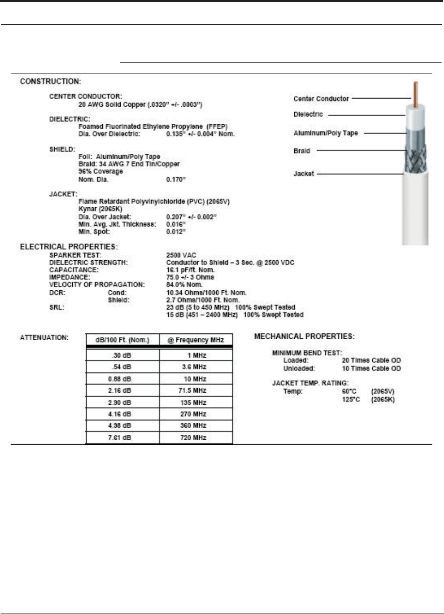
A-2 InterReach Fusion Wideband Installation, Operation, and Reference Manual
CONFIDENTIAL D-620616-0-20 Rev G
Figure 0-1 CommScope 2065V for RG-59
Help Hot Line (U.S. only): 1-800-530-9960 A-3
D-620616-0-20 Rev G CONFIDENTIAL
Figure 0-2 CommScope 2279V for RG-6
A-4 InterReach Fusion Wideband Installation, Operation, and Reference Manual
CONFIDENTIAL D-620616-0-20 Rev G
Figure 0-3 CommScope 2293K for RG-11
NOTE: TE requires solid copper center conductor CATV cable for proper
DC voltage to the RAU and maximum distances.

Help Hot Line (U.S. only): 1-800-530-9960 A-5
D-620616-0-20 Rev G CONFIDENTIAL
Use the following connectors and tools to prepare the cable ends:
CommScope cable part number: 2065V
Canare part number: F connector FP-C4F
Crimp Tool TC-1, Crimp Die TCD-4C, Cable Strip preparation tool TS100E
CommScope cable part number: 2279V
Canare part number: F connector FP-C55A
Crimp Tool TC-1, Crimp Die TCD-35CA, Cable Strip preparation tool TS100E
CommScope cable part number: 2293V
Canare part number: F connector FP-C71A
Crimp Tool TC-1, Crimp Die TCD-7CA, Cable Strip preparation tool TS100E
If the maximum distance is not required, then copper-clad over steel-center conductor
cable may be used to reduce cable costs.
Table A-2 shows CommScope cable choices of plenum, non-plenum, solid copper
conductor, and copper-clad over-steel conductor cable with their part numbers and
maximum distances.

Table A-1 System Gain (Loss) Relative to CATV Cable Length
Cable
Type
Comm-
Scope
Part
Number Plenum
Rated
Solid
Copper
Conductor
Copper
Clad
Conductor
Zero-loss
RF
Maximum
Length
(meters)
Distance
Where
RF is
10dB
Below
Input RF
(meters)
RG-59
2065V Yes X 130 180
2022V Yes X 100 100*
5572R No X 95 95*
5565 No X 130 180
RG-6
2279V Yes X 140 190
2275V Yes X 140 150*
5726 No X 140 140*
5765 No X 140 190
RG-11
2293K Yes X 235 320
2285K Yes X 235 300*
5913 No X 235 300*
A-6 InterReach Fusion Wideband Installation, Operation, and Reference Manual
CONFIDENTIAL D-620616-0-20 Rev G
* Exceeding the distance of copper-clad cable will result in the attached RAU becoming
non-functional. If the distance of a cable run is at its maximum and is of concern, TE recom-
mends the use of solid copper cable to ensure successful operation.
A.2 Fiber Optical Cables
• Connects the Main Hub to Expansion Hub(s)
• Transmits (downlink) and receives (uplink) optical signals
• Carries configuration and status information
• Use industry-standard 62.5m/125m MMF or Corning SMF-28 fiber, or equiva-
lent.
• SC/APC (angle-polished) connectors are required throughout the fiber network
(port-to-port), including fiber distribution panels

Help Hot Line (U.S. only): 1-800-530-9960 A-7
D-620616-0-20 Rev G CONFIDENTIAL
• Distances:
• Multi-mode Fiber: up to 500 m (1,640 ft) – 3 dB optical loss maximum
• Single-mode Fiber: up to 6 km (19,685 ft) – 3 dB optical loss maximum
A.3 Coaxial Cable
• Connects a Fusion Wideband Hub to a repeater or base station (N-type connectors)
• Connects an RAU to a passive antenna (N-type connectors)
A.4 Standard Modem Cable
This cable (PN 4028-10) connects a modem to the Fusion Wideband Hub’s front
panel serial port.
Figure A-1 Standard Modem Cable Pinout
DB-9 Connector
Pin DB-25 Connector
Pin
1
2
3
4
5
6
7
8
9
8
3
2
20
7
6
4
5
22
A-8 InterReach Fusion Wideband Installation, Operation, and Reference Manual
CONFIDENTIAL D-620616-0-20 Rev G
A.5 TCP/IP Cross-over Cable
A TCP/IP cross-over cable (PN 4069-ADB) is used to connect a standard browser PC
to the AdminBrowser with a Fusion Wideband Hub. A cable is included with the
Fusion Wideband Hub. The pinouts for this cable are illustrated in Figure A-2.
Figure A-2 Wiring Map for TCP/IP Cable
12 3 4 5 6 78
Brown
Brown/
White
Blue Blue/
White
Green/
White
Green Orange
Orange/
White
RJ-45 Port
12345678
W-G
G
W-O
BL
W-BL
O
W-BR
BR
RJ-45 Port
12345678
W-O
O
W-G
BL
W-BL
G
W-BR
BR
361
452 78
Connector 1
Connector 2
(586A)
(586B)

Help Hot Line (U.S. only): 1-800-530-9960 A-9
D-620616-0-20 Rev G CONFIDENTIAL
A.6 DB-9 to DB-9 Null Modem Cable
Use a DB-9 female to DB-9 female null modem cable to connect the craft person’s
PC/Laptop to the RS-232 port on the front of the Fusion Wideband Hub for IP
address configuration. Table A-2 lists the cable pinout and Figure A-3 shows a dia-
gram of its wiring.
Table A-2 DB-9 Female to DB-9 Female Null Modem Cable Pinout
From Signal To Signal
P1-4 DTR P2-6, P2-1 DSR, DCD
P1-6 DSR P1-1, P2-4 DCD, DTR
P1-3 TXD P2-2 RXD
P1-2 RXD P2-3 TXD
P1-5 GND P2-5 GND
P1-7 RTS P2-8 CTS
P1-8 CTS P2-7 RTS
P1-9 N/C N/C N/C
Figure A-3 DB-9 Female to DB-9 Female Null Modem Cable Diagram
Note that for each DB-9 connector, pins 1 and 6 are tied together and sent to pin 4
of the opposite connector, providing the required handshake signals.
DB-9
Connector
Pin
DB-9
Connector
Pin
1
2
3
4
5
6
7
8
9
1
2
3
4
5
6
7
8
9

A-10 InterReach Fusion Wideband Installation, Operation, and Reference Manual
CONFIDENTIAL D-620616-0-20 Rev G

InterReach Fusion Wideband Installation, Operation, and Reference Manual B-1
D-620616-0-20 Rev G CONFIDENTIAL
APPENDIX B Compliance
B.1 Fusion Wideband System Approval Status
InterReach Fusion Wideband has been approved as shown below.
700 MHz LTE Products
• Safety: UL, CSA, CB Scheme certificate to IEC 60950, 3rd Edition, and IEC
60950-1, 1st Edition, with all national deviations.
• EMC: FCC part 15 class A
• Radio: FCC part 27
800 SMR/iDEN Products
• Safety: UL, CSA, CB Scheme certificate to IEC 60950, 3rd Edition, and IEC
60950-1, 1st Edition, with all national deviations.
• EMC: FCC part 15 class A
• Radio: FCC part 90
850 Cellular Products
• Safety: UL, CSA, CB Scheme certificate to IEC 60950, 3rd Edition, and IEC
60950-1, 1st Edition, with all national deviations.
• EMC: FCC part 15 class A
• Radio: FCC part 22

B-2 InterReach Fusion Wideband Installation, Operation, and Reference Manual
CONFIDENTIAL D-620616-0-20 Rev G
1800 DCS Products
• Safety: UL, CSA, CB Scheme certificate to IEC 60950, 3rd Edition, and IEC
60950-1, 1st Edition, with all national deviations.
• EMC: EN 301 489-8 V1.2.1
• Radio: EN 301 502 V8.1.2
1900 PCS Products
• Safety: UL, CSA, CB Scheme certificate to IEC 60950, 3rd Edition, and IEC
60950-1, 1st Edition, with all national deviations.
• EMC: FCC part 15 class A
• Radio: FCC part 24
2100 UMTS Products
• Safety: UL, CSA, CB Scheme certificate to IEC 60950, 3rd Edition, and IEC
60950-1, 1st Edition, with all national deviations.
• EMC: EN 301 489-23 V1.2.1
• Radio: EN 301 908-11 V2.3.1
1700/2100 AWS Products
• Safety: UL, CSA, CB Scheme certificate to IEC 60950, 3rd Edition, and IEC
60950-1, 1st Edition, with all national deviations.
• EMC: FCC part 15 class A
• Radio: FCC part 27
2500 WiMAX Products
• Safety: UL, CSA, CB Scheme certificate to IEC 60950, 3rd Edition, and IEC
60950-1, 1st Edition, with all national deviations.
• EMC: FCC part 15 class A
• Radio: FCC part 27
2600 MHz LTE Products
• Safety: UL, CSA, CB Scheme certificate to IEC 60950, 3rd Edition, and IEC
60950-1, 1st Edition, with all national deviations.
• EMC: EN 301 489-23 V1.2.1
• Radio: EN 301 908-11 V2.3.1

Help Hot Line (U.S. only): 1-800-530-9960 B-3
D-620616-0-20 Rev G CONFIDENTIAL
InterReach Fusion Wideband Main Hub and Expansion Hub
• Safety: UL, CSA, CB Scheme certificate to IEC 60950-1, First Edition, with all
national deviations.
• EMC: CISPR 22A
• EMC: CISPR 24
NOTE: For Canadian customers, the Manufacturer’s rated output power1 of
this equipment is for single carrier operation. For situations when multiple
carrier signals are present, the rating would have to be reduced by 3.5 dB,
especially where the output signal is re-radiated and can cause interference
to adjacent band users. This power reduction is to be by means of input
power or gain reduction and not by an attenuator at the output of the device.
NOTE: This device complies with Part 15 of the FCC Rules. Operation is
subject to the following two conditions: (1) this device may not cause harm-
ful interference, and (2) this device must accept any interference received,
including interference that may cause undesired operation.
NOTE: This equipment has been tested and found to comply with the limits
for a Class A digital device, pursuant to Part 15 of the FCC Rules. These
limits are designed to provide reasonable protection against harmful interfer-
ence when the equipment is operated in a commercial environment. This
equipment generates, uses, and can radiate radio frequency energy and, if
not installed and used in accordance with the instruction manual, may cause
harmful interference to radio communications.
This equipment complies with the FCC radiation exposure limits for general popula-
tion/uncontrolled exposure environments.
Changes or modifications not approved and performed by TE may void the user’s
authority to operate the equipment.
1. “Manufacturer’s rated output power” refers to Fusion Wideband’s downlink P1dB. The power per carrier tables take
into account this power reduction for multiple carriers.

B-4 InterReach Fusion Wideband Installation, Operation, and Reference Manual
CONFIDENTIAL D-620616-0-20 Rev G
B.2 Human Exposure to RF
The U.S. Federal Communications Commission (FCC) has developed guidelines for
evaluation of human exposure to RF emissions. The guidelines incorporate limits for
Maximum Permissible Exposure (MPE) for power density of transmitters operating
at frequencies between 300 kHz and 100 GHz. Limits have been set for portable,
mobile, and fixed equipment. TE products fall in the category of fixed equipment;
products intended to be permanently secured and exposures are evaluated for dis-
tances greater than 20cm (7 7/8”). Portable devices fall into exposures of less than
20cm, are SAR evaluations are used.
Antenna gain is restricted to 1.45 W ERP (2.37 W EIRP) in order to satisfy RF expo-
sure compliance requirements. If higher than 1.45 W ERP, routine MPE evaluation is
needed. The antennas should be installed to provide at least 20 cm from all persons to
satisfy MPE requirements of FCC Part 2, 2.1091.
Basic MPE evaluation is performed by taking the maximum power output of the
equipment, the gain of the antenna to be used, and distance from the antenna, refer-
enced in FCC OET Bulletin 65 “Evaluation Compliance with FCC Guidelines for
Human Exposure to Radio Frequency for Electric Fields”.
TE products transmit well below the FCC power density limits. FCC defines power
output limits at 20cm distance for various frequency ranges:
• Over 300 mHz to 1.5 GHz the limit is determined by frequency/1500
• Above 1.5 GHz the limit is 1mW/cm2
The basic equation for determining power density is:
S = PG / 4SR2
Where S is power density in mW/cm2
PG, the transmitted power from the antenna identified as EIRP (Equivalent Isotropi-
cally Radiated Power), is the product of power output of device and antenna gain, in
mW.
R is the distance of interest from the antenna.
Typical Installation Example:
Assuming an antenna is placed on a 10 foot ceiling, for a person 6 feet tall, the dis-
tance from antenna to body is 4 feet (112 cm.).
For a PCS 1900 remote unit, the maximum power output, according to the power
Assuming a 7 dBi antenna is used, PG in the equation is equal to 25/30 dB (316/1000 mW)
EIRP.
The minimum separation distance of the equipment to the user is 20cm.
table in Section 6.3 Maximum Output Power per Carrier on page 6-4, is 18/23dB.

Help Hot Line (U.S. only): 1-800-530-9960 B-5
D-620616-0-20 Rev G CONFIDENTIAL
Using S = PG/4SR2
S = 316/(4x3.14) x (112)2 = 0.002 mW/cm2
Also, assuming a minimum distance of 20 cm according to FCC regulations”
S = 1000/(4x3.14) x (112)2 = 0.006 mW/cm 2
S = 316/(4x3.14) x (20)2 = 0.063 mW/cm
S = 1000/(4x3.14) x (20)2
= 0.199 mW/cm
1. Maximum conduction output power:P
max
(18/23dBm)
2. Maximum conduction output power allows output biggest antenna gain:
G
mpmax
(13.6dBD/10.75dBi)
3. Set the real power: P
4. Power deviation value( ) = Maximum conduction output power-Set the real power
5. Maximum allowable antenna gain( )=
ΔP=P
max
-P
ΔP
G
max
G
mpmax
+ΔP

B-6 InterReach Fusion Wideband Installation, Operation, and Reference Manual
CONFIDENTIAL D-620616-0-20 Rev G

InterReach Fusion Wideband Installation, Operation, and Reference Manual C-1
D-620616-0-20 Rev G CONFIDENTIAL
APPENDIX C Faults, Warnings, Status Tables
for Fusion, Fusion Wideband,
Fusion SingleStar
This appendix contains the following sections:
• Section C.1 Faults Reported by Main Hubs . . . . . . . . . . . . . . . . . . . . . . . . . . C-1
• Section C.2 Faults Reported for System CPU . . . . . . . . . . . . . . . . . . . . . . . . C-5
• Section C.3 Faults for Expansion Hubs . . . . . . . . . . . . . . . . . . . . . . . . . . . . . C-6
• Section C.4 Faults for RAUs . . . . . . . . . . . . . . . . . . . . . . . . . . . . . . . . . . . . . C-9
• Section C.5 Messages for Main Hubs . . . . . . . . . . . . . . . . . . . . . . . . . . . . . C-10
• Section C.6 Messages for System CPUs . . . . . . . . . . . . . . . . . . . . . . . . . . . C-15
• Section C.7 Messages for Expansion Hubs . . . . . . . . . . . . . . . . . . . . . . . . . C-16
• Section C.8 Messages for RAUs . . . . . . . . . . . . . . . . . . . . . . . . . . . . . . . . . C-19
The following tables contain messages for all versions of firmware, but all messages
are not displayed by a given firmware version.
C.1 Faults Reported by Main Hubs
Faults indicate service-impacting conditions and should be given immediate atten-
tion.
Once all of the units are powered on and the cable connections are made, the faults
from each unit can be requested using AdminBrowser. Start with the Fusion or Fusion
Wideband Main Hub and work downstream.
Resolve all faults first and then check the warnings. Take appropriate action to
resolve the faults, as indicated in the following tables. In cases where there is more
than one possible cause, they are listed from the “most likely” to the “least likely”
cause. Actions are listed in the order that they should be performed; not all actions
may need to be done.

C-2 InterReach Fusion Wideband Installation, Operation, and Reference Manual
CONFIDENTIAL D-620616-0-20 Rev G
NOTE: If you have a red STATUS LED without a fault message, it probably
indicates that the unit is locked out.
Table C-1 Fault Messages for Main Hubs
Message
Number Description Reason/Action
{MF01} Software error occurred and recovered. If this happens repeatedly, replace the Hub.
{MF02} Software error occurred and recovered. If this happens repeatedly, replace the Hub.
{MF03} Software error occurred and recovered. If this happens repeatedly, replace the Hub.
{MF04} Software reset occurred and recovered, or
firmware download. If this happens repeatedly, replace the Hub.
{MF05} Software error occurred and recovered. If this happens repeatedly, replace the Hub.
{MF06} Problem detected in the Hub. Internal
communication reset. Contact TE Support for more information.
{MF07} Hub power cycle. Hub power cycle.
{MF08} Internal communications failure. No internal communications in preceding 15 min-
utes.
{MF09} Hardware Reset. Commanded hardware power on reset
{MF10} Band not programmed. Use AdminBrowser to program the band.
{MF11} Hardware failure (DL Pilot PLL). Cycle power once. If fault persists, replace the Hub
{MF12} Hardware failure (DL Pilot Too High). Cycle power once. If fault persists, replace the Hub.
{MF13} Hardware failure (DL Pilot Too Low). Cycle power once. If fault persists, replace the Hub.
{MF14} Hardware failure (54 VDC). 54 VDC power supply is out of range, replace the
Hub
{MF15} Hardware failure (RF VDC Power). Loss of DC power to RF circuits, replace the Hub.
{MF16} Self Lockout (All Bands). Hub has shutdown the system due to an internal fault.
System is offline.
{MF17} Hardware failure (DL PLL Band 1). Cycle power once. If fault persists, replace the Hub.
{MF18} Hardware failure (UL PLL Band 1). Cycle power once. If fault persists, replace the Hub
{ML19} Commanded Out-of-service (Band 1). Band 1 commanded out-of-service by User.
{MF20} Hardware failure (UL1 LO2 Band 1). Cycle power once. If the fault persists, replace the
Hub.
{MF21} Problem detected in the Hub. Contact TE Support for more information.
{MF22} Problem detected in the Hub. Contact TE Support for more information.
{MF23} Problem detected in the Hub Contact TE Support for more information.
{MF24} Problem detected in the Hub. Contact TE Support for more information.
{MF25} Hardware failure (DL PLL Band 2). Cycle power once. If fault persists, replace the Hub.
{MF26} Hardware failure (UL PLL Band 2). Cycle power once. If fault persists, replace the Hub.
{ML27} Commanded Out-of-service (Band 2). Band 2 commanded out-of-service by User.
{MF28} Problem detected in the Hub. Contact TE Support for more information.
{MF29} Problem detected in the Hub. Contact TE Support for more information.
{MF30} Problem detected in the Hub. Contact TE Support for more information.
{MF31} Problem detected in the Hub. Contact TE Support for more information.
{MF32} Problem detected in the Hub. Contact TE Support for more information.

Help Hot Line (U.S. only): 1-800-530-9960 C-3
D-620616-0-20 Rev G CONFIDENTIAL
{MF33} Hardware failure (DL PLL Band 3). Cycle power once. If fault persists, replace the Hub.
{MF34} Hardware failure (UL PLL Band 3). Cycle power once. If fault persists, replace the Hub.
{ML35} Commanded Out-of-service (Band 3). Band 3 commanded out-of-service by User.
{MF36} Hardware failure (638 MHz PLL). Cycle power once. If fault persists, replace the Hub.
{MF37} Hardware failure (656 MHz PLL). Cycle power once. If fault persists, replace the Hub.
{MF38} Problem detected in the Hub. Contact TE Support for more information.
{MF39} Problem detected in the Hub. Contact TE Support for more information.
{MF40} Problem detected in the Hub. Contact TE Support for more information.
{MF41} Hardware failure (Optical Power Out). Cycle power once. If the fault persists, replace the
Hub.
{MF42} Unable to sync with TDD frame (Band 1). Check input signal and/or user TDD settings.
{MF43} Unable to sync with TDD frame (Band 2). Check input signal and/or user TDD settings.
{MF44} Unable to determine number of TDD
symbols (Band 1). Make sure that the WiMAX signal has a valid num-
ber of downlink symbols. If the value is okay, try
selecting a fixed number of symbols.
{MF45} Unable to determine number of TDD
symbols (Band 2). Make sure that the WiMAX signal has a valid num-
ber of downlink symbols. If the value is okay, try
selecting a fixed number of symbols.
{MF46} Problem detected in the Hub. Contact TE Support for more information.
{MF47} Problem detected in the Hub Contact TE Support for more information.
{MF48} Problem detected in the Hub. Contact TE Support for more information.
{MD129} Port 1 Disconnected. Unit is disconnected.
{MD130} Port 2 Disconnected. Unit is disconnected.
{MD131} Port 3 Disconnected. Unit is disconnected.
{MD132} Port 4 Disconnected. Unit is disconnected.
{MD133} Port 5 Disconnected. Unit is disconnected.
{MD134} Port 6 Disconnected. Unit is disconnected.
{MD135} Port 7 Disconnected. Unit is disconnected.
{MD136} Port 8 Disconnected. Unit is disconnected.
{MC137} Port 1 No Communications. No communications with remote unit.
{MC138} Port 2 No Communications. No communications with remote unit.
{MC139} Port 3 No Communications. No communications with remote unit.
{MC140} Port 4 No Communications. No communications with remote unit.
{MC141} Port 5 No Communications. No communications with remote unit.
{MC142} Port 6 No Communications. No communications with remote unit.
{MC143} Port 7 No Communications. No communications with remote unit.
{MC144} Port 8 No Communications. No communications with remote unit.
{MT145} Port 1 Cable Fault. Possible electrical short in the coax cable, or RAU
problem.
{MT146} Port 2 Cable Fault. Possible electrical short in the coax cable, or RAU
problem.
{MT147} Port 3 Cable Fault. Possible electrical short in the coax cable, or RAU
problem.
Table C-1 Fault Messages for Main Hubs (continued)
Message
Number Description Reason/Action

C-4 InterReach Fusion Wideband Installation, Operation, and Reference Manual
CONFIDENTIAL D-620616-0-20 Rev G
{MT148} Port 4 Cable Fault. Possible electrical short in the coax cable, or RAU
problem.
{MT149} Port 5 Cable Fault. Possible electrical short in the coax cable, or RAU
problem.
{MT150} Port 6 Cable Fault. Possible electrical short in the coax cable, or RAU
problem.
{MT151} Port 7 Cable Fault. Possible electrical short in the coax cable, or RAU
problem.
{MT152} Port 8 Cable Fault. Possible electrical short in the coax cable, or RAU
problem.
{MT153} Port 1 Trip. Remote Unit is drawing too much current.
{MT154} Port 2 Trip. Remote Unit is drawing too much current.
{MT155} Port 3 Trip. Remote Unit is drawing too much current.
{MT156} Port 4 Trip. Remote Unit is drawing too much current.
{MT157} Port 5 Trip. Remote Unit is drawing too much current.
{MT158} Port 6 Trip. Remote Unit is drawing too much current.
{MT159} Port 7 Trip. Remote Unit is drawing too much current.
{MT160} Port 8 Trip. Remote Unit is drawing too much current.
{MF161} Problem detected in the Hub. Contact TE Support for more information.
{MF162} Problem detected in the Hub. Contact TE Support for more information.
{MF163} Problem detected in the Hub. Contact TE Support for more information.
{MF164} Problem detected in the Hub. Contact TE Support for more information.
{MF165} Problem detected in the Hub. Contact TE Support for more information.
{MF166} Problem detected in the Hub. Contact TE Support for more information.
{MF167} Problem detected in the Hub. Contact TE Support for more information.
{MF168} Problem detected in the Hub. Contact TE Support for more information.
{MF169} Problem detected in the Hub. Contact TE Support for more information.
{MF170} Problem detected in the Hub. Contact TE Support for more information.
{MF171} Problem detected in the Hub. Contact TE Support for more information.
{MF172} Problem detected in the Hub. Contact TE Support for more information.
{MF173} Problem detected in the Hub. Contact TE Support for more information.
{MF174} Problem detected in the Hub. Contact TE Support for more information.
{MF175} Problem detected in the Hub. Contact TE Support for more information.
{MF176} Problem detected in the Hub. Contact TE Support for more information.
Table C-1 Fault Messages for Main Hubs (continued)
Message
Number Description Reason/Action

Help Hot Line (U.S. only): 1-800-530-9960 C-5
D-620616-0-20 Rev G CONFIDENTIAL
C.2 Faults Reported for System CPU
Table C-2 Faults for System CPU
Message
Number Description Reason/Action
{SF01} No internal communications. No internal communications in preceding 2 minutes.
Power cycle to clear.
{SF02} Unable to open file (sysinfo). System CPU rebooted.
{SF03} Unable to open file (sysstat). System CPU rebooted.
{SF04} Invalid internal response. System CPU rebooted, internal command does not
return valid response after 4 retries.
{SF05} No MAC address. System CPU rebooted, unable to read MAC address
from the Ethernet driver.
{SF06} Unable to open file (sysinfo_org). System CPU rebooted.
{SF07} Unable to open file (sbc_status). System CPU rebooted.
{SF08} Invalid internal field response. System CPU rebooted, internal command format
invalid.
{SF09} Unable to open file (fileTTL). System CPU rebooted.
{SF10} Invalid internal ASCII response. System CPU rebooted, illegal number of bytes.
{SF11} Unable to open file (sysalarm). System CPU rebooted.
{SF12} Unable to open file (password_etb). System CPU rebooted.
{SF13} Unable to open file (CRC). System CPU rebooted.
{SF14} Problem detected in the System CPU. Contact TE Support for more information.
{SF15} pThread not executing. System CPU rebooted.
{SF16} Problem detected in the System CPU. Contact TE Support for more information.
{SF17} Problem detected in the System CPU. Contact TE Support for more information.
{SF18} Problem detected in the System CPU. Contact TE Support for more information.
{SF19} Problem detected in the System CPU. Contact TE Support for more information.
{SF20} Problem detected in the System CPU. Contact TE Support for more information.
{SF21} Problem detected in the System CPU. Contact TE Support for more information.
{SF22} Problem detected in the System CPU. Contact TE Support for more information.
{SF23} Problem detected in the System CPU. Contact TE Support for more information.
{SF24} Problem detected in the System CPU. Contact TE Support for more information.
{SF25} Problem detected in the System CPU. Contact TE Support for more information.
{SF26} Problem detected in the System CPU. Contact TE Support for more information.
{SF27} Problem detected in the System CPU. Contact TE Support for more information.
{SF28} Problem detected in the System CPU. Contact TE Support for more information.
{SF29} Problem detected in the System CPU. Contact TE Support for more information.
{SF30} Problem detected in the System CPU. Contact TE Support for more information.
{SF31} Problem detected in the System CPU. Contact TE Support for more information.
{SF32} Problem detected in the System CPU. Contact TE Support for more information.

C-6 InterReach Fusion Wideband Installation, Operation, and Reference Manual
CONFIDENTIAL D-620616-0-20 Rev G
C.3 Faults for Expansion Hubs
Table C-3 Fault Messages for Expansion Hubs
Message
Number Description Reason/Action
{EF01} Software error occurred
and recovered. If this happens repeatedly, replace the Hub.
{EF02} Software reset occurred
and recovered, or firm-
ware download.
If this happens repeatedly, replace the Hub.
{EF03} Software reset occurred
and recovered. If this happens repeatedly, replace the Hub.
{EF04} Software reset occurred
and recovered. If this happens repeatedly, replace the Hub.
{EF05} Software error occurred
and recovered. If this happens repeatedly, replace the Hub.
{EF06} Firmware download. Firmware download.
{EF07} Hub power cycle. Hub power cycle.
{EF08} MH communications fail-
ure. No communications from MH in THE preceding 90 seconds.
{EF09} MH communications fail-
ure. EH uplink messages not getting to the MH.
{EF10} Hardware failure (PLL). Cycle power once. If the fault persists, replace the Hub.
{EF11} Hardware failure (54
VDC). 54 VDC power supply is out of range, replace the Hub.
{EF12} Problem detected in the
EH. Contact TE Support for more information.
{EF13} Band not programmed. Cycle power once. If the fault persists, replace the Hub.
{EF14} Low optical input power. Check downlink fiber connections.
{EF15} Hardware failure (Optical
Output Power). Cycle power once. If the fault persists, replace the Hub.
{EF16} Self Lockout (All Bands). The Hub has shutdown the system due to an internal fault. The sys-
tem is offline.
{EF17} Commanded Out-of-ser-
vice (Band 1). Band 1 commanded out-of-service by the user.
{EF18} Fault lockout (Band 1). Band 1 out-of-service due to an MH fault.
{EF19} Problem detected in the
EH. Contact TE Support for more information.
{EF20} Problem detected in the
EH. Contact TE Support for more information.
{EF21} Problem detected in the
EH. Contact TE Support for more information.
{EF22} Problem detected in the
EH. Contact TE Support for more information.
{EF23} Problem detected in the
EH. Contact TE Support for more information.
{EF24} Problem detected in the
EH. Contact TE Support for more information.
{EF25} Commanded Out-of-ser-
vice (Band 2). Band 2 commanded out-of-service by the user.

Help Hot Line (U.S. only): 1-800-530-9960 C-7
D-620616-0-20 Rev G CONFIDENTIAL
{EF26} Fault lockout (Band 2). Band 2 out-of-service due to MH fault.
{EF27} Problem detected in the
EH. Contact TE Support for more information.
{EF28} Problem detected in the
EH. Contact TE Support for more information.
{EF29} Problem detected in the
EH. Contact TE Support for more information.
{EF30} Problem detected in the
EH. Contact TE Support for more information.
{EF31} Problem detected in the
EH. Contact TE Support for more information.
{EF32} Problem detected in the
EH. Contact TE Support for more information.
{EF33} Commanded Out-of-ser-
vice (Band 3). Band 3 commanded out-of-service by the user.
{EF34} Fault lockout (Band 3). Band 3 out-of-service due to an MH fault.
{EF35} Problem detected in the
EH. Contact TE Support for more information.
{EF36} Problem detected in the
EH. Contact TE Support for more information.
{EF37} Problem detected in the
EH. Contact TE Support for more information.
{EF38} Problem detected in the
EH. Contact TE Support for more information.
{EF39} Problem detected in the
EH. Contact TE Support for more information.
{EF40} Problem detected in the
EH. Contact TE Support for more information.
{ED129} Port 1 Disconnected. Unit is disconnected.
{ED130} Port 2 Disconnected. Unit is disconnected.
{ED131} Port 3 Disconnected. Unit is disconnected.
{ED132} Port 4 Disconnected. Unit is disconnected.
{ED133} Port 5 Disconnected. Unit is disconnected.
{ED134} Port 6 Disconnected. Unit is disconnected.
{ED135} Port 7 Disconnected. Unit is disconnected.
{ED136} Port 8 Disconnected. Unit is disconnected.
{EC137} Port 1 No Communica-
tions. No communications with remote unit.
{EC138} Port 2 No Communica-
tions. No communications with remote unit.
{EC139} Port 3 No Communica-
tions. No communications with remote unit.
{EC140} Port 4 No Communica-
tions. No communications with remote unit.
{EC141} Port 5 No Communica-
tions. No communications with remote unit.
{EC142} Port 6 No Communica-
tions. No communications with remote unit.
Table C-3 Fault Messages for Expansion Hubs (continued)
Message
Number Description Reason/Action

C-8 InterReach Fusion Wideband Installation, Operation, and Reference Manual
CONFIDENTIAL D-620616-0-20 Rev G
{EC143} Port 7 No Communica-
tions. No communications with remote unit.
{EC144} Port 8 No Communica-
tions. No communications with remote unit.
{ET145} Port 1 Cable Fault. Possible electrical short in the coaxial cable, or an RAU problem.
{ET146} Port 2 Cable Fault. Possible electrical short in the coaxial cable, or an RAU problem.
{ET147} Port 3 Cable Fault. Possible electrical short in the coaxial cable, or an RAU problem.
{ET148} Port 4 Cable Fault. Possible electrical short in the coaxial cable, or an RAU problem.
{ET149} Port 5 Cable Fault. Possible electrical short in the coaxial cable, or an RAU problem.
{ET150} Port 6 Cable Fault. Possible electrical short in the coaxial cable, or an RAU problem.
{ET151} Port 7 Cable Fault. Possible electrical short in the coaxial cable, or an RAU problem.
{ET152} Port 8 Cable Fault. Possible electrical short in the coaxial cable, or an RAU problem.
{ET153} Port 1 Trip. The Remote Unit is drawing too much current.
{ET154} Port 2 Trip. The Remote Unit is drawing too much current.
{ET155} Port 3 Trip. The Remote Unit is drawing too much current.
{ET156} Port 4 Trip. The Remote Unit is drawing too much current.
{ET157} Port 5 Trip. The Remote Unit is drawing too much current.
{ET158} Port 6 Trip. The Remote Unit is drawing too much current.
{ET159} Port 7 Trip. The Remote Unit is drawing too much current.
{ET160} Port 8 Trip. The Remote Unit is drawing too much current.
Table C-3 Fault Messages for Expansion Hubs (continued)
Message
Number Description Reason/Action

Help Hot Line (U.S. only): 1-800-530-9960 C-9
D-620616-0-20 Rev G CONFIDENTIAL
C.4 Faults for RAUs
Table C-4 Faults for RAUs
Message
Number Description Reason/Action
{RF01} Software error occurred and recovered. If this happens repeatedly, replace the RAU.
{RF02} Software error occurred and recovered. If this happens repeatedly, replace the RAU.
{RF03} Software error occurred and recovered. If this happens repeatedly, replace the RAU.
{RF04} Software reset occurred and recovered,
or firmware download. If this happens repeatedly, replace the RAU.
{RF05} Software error occurred and recovered. If this happens repeatedly, replace the RAU.
{RF06} Problem detected in the RAU. Contact TE Support for more information.
{RF07} RAU power cycle. RAU power cycle.
{RF08} Problem detected in the RAU. Contact TE Support for more information.
{RF09} Invalid band. The RAU doesn't support programmed band. Check the
RAU type against the band programmed in the hub.
{RF10} Low input DC voltage. Check the coaxial cable for high RF loss. Try another
Hub port. If the fault persists, replace the RAU. If the
fault clears, mark the Hub port as unusable and replace
the Hub when possible.
{RF11} Hardware Failure (DL PLL Band 1). Cycle power once. If the fault persists, replace the RAU.
{RF12} Hardware Failure (DL PLL Band 2). Cycle power once. If the fault persists, replace the RAU.
{RF13} Hardware Failure (DL PLL Band 3). Cycle power once. If the fault persists, replace the RAU.
{RF14} Hardware Failure (UL PLL Band 1). Cycle power once. If the fault persists, replace the RAU.
{RF15} Hardware Failure (UL PLL Band 2). Cycle power once. If the fault persists, replace the RAU.
{RF16} Hardware Failure (UL PLL Band 3). Cycle power once. If the fault persists, replace the RAU.
{RF17} Hardware Failure (PA Band 1). Cycle power once. If the fault persists, replace the RAU.
{RF18} Hardware Failure (PA Band 2). Cycle power once. If the fault persists, replace the RAU.
{RF19} Hardware Failure (PA Band 3). Cycle power once. If the fault persists, replace the RAU.
{RF20} Hardware Failure (UL Pilot). Cycle power once. If the fault persists, replace the RAU.
{RL21} Commanded Out-of-service (Band 1). Band 1 commanded out-of-service by User. Command
In-Service on Band 1 to restore service.
{RL22} Commanded Out-of-service (Band 2). Band 2 commanded out-of-service by User. Command
In-Service on Band 2 to restore service.
{RL23} Commanded Out-of-service (Band 3). Band 3 commanded out-of-service by User. Command
In-Service on Band 3 to restore service.
{RF24} Problem detected in the RAU. Contact TE Support for more information.
{RX25} Commanded shutdown (Band 1). Check the status of hub to which the RAU is connected.
{RX26} Commanded shutdown (Band 2). Check the status of hub to which the RAU is connected.
{RX27} Commanded shutdown (Band 3). Check the status of the hub to which the RAU is con-
nected.
{RF28} Internal shutdown (Band 1). RAU Fault condition in band 1 path (or common path).
{RF29} Internal shutdown (Band 2). RAU Fault condition in band 2 path (or common path).
{RF30} Internal shutdown (Band 3). RAU Fault condition in band 3 path (or common path).
{RF31} Hardware Failure (UL PLL2 Band 1). Cycle power once. If the fault persists, replace the RAU.
{RF32} Problem detected in the RAU. Contact TE Support for more information.

C-10 InterReach Fusion Wideband Installation, Operation, and Reference Manual
CONFIDENTIAL D-620616-0-20 Rev G
C.5 Messages for Main Hubs
Warning Messages
Warnings alert you to conditions that indicate possible service impact. Warnings are
displayed in the Messages pane in red lettering.
Before addressing warnings, ensure that all faults are resolved. Take appropriate
action to resolve the warnings, as indicated in the following tables.
NOTE: AdminBrowser v000007 or higher displays events (faults, warn-
ings, or status messages) depending on your view preference. To change
your view preference, refer to Section 3.5, “Faults, Warnings, and Status
Messages” of the Fusion Installation, Operation, and Maintenance Manual.
Status Messages
Status messages alert you to conditions that are important, but generally do not
impact service. Status messages alert you to conditions that are important, but gener-
ally do not impact service. Status messages are displayed in the Messages pane in
blue lettering.
NOTE: AdminBrowser v000007 or higher displays events (faults, warn-
ings, or status messages) depending on your view preference. To change
your view preference, refer to Section 3.5, “Faults, Warnings, and Status
Messages” of the Fusion Installation, Operation, and Maintenance Manual.
NOTE: The icons displayed in the system status tree assume that there are
no other faults, warnings, or status present.
In Table C-5, the message number is in the following form:
[Mnn]/X where nn equals the message number, and X equals the default of either Sta-
tus (S) or Warning (W).

Help Hot Line (U.S. only): 1-800-530-9960 C-11
D-620616-0-20 Rev G CONFIDENTIAL
Table C-5 Warnings/Status Messages for Main Hubs
Message
Number/
Default Description Reason/Action
[M01]/S Fan 1 failure. Check the fan for rotation, air flow blockage, and dust.
Replace the Hub on high temperature warning.
[M02]/S Fan 2 failure. Check the fan for rotation, air flow blockage, and dust.
Replace the Hub on high temperature warning.
[M03]/S 54 VDC Pwr Supply Fan failure. Check the fan for rotation, air flow blockage, and dust.
Replace the Hub on high temperature warning.
[M04]/W 5 VDC Monitor. DC power out of range, replace the Hub.
[M05]/W 9 VDC Monitor. DC power out of range, replace the Hub.
[M06]/W 54 VDC Monitor. DC power out of range, replace the Hub.
[M07]/W 3 VDC Monitor. DC power out of range, replace the Hub.
[M08]/W 12 VDC Monitor. DC power out of range, replace the Hub.
[M09]/W Temperature High. Reduce ambient temperature, check for air flow blockage,
fan rotation.
[M10]/W -5 VDC Monitor. DC power is out of range, replace the Hub.
[M11]/W High laser current. Output laser failure possible, replace the Hub when possi-
ble.
[M12]/W DL path loss is too high Replace the Hub.
[M13]/S Low input optical (Port 1). Check the uplink fiber.
[M14]/S Low input optical (Port 2). Check the uplink fiber.
[M15]/S Low input optical (Port 3). Check the uplink fiber.
[M16]/S Low input optical (Port 4). Check the uplink fiber.
[M17]/S Hardware failure (Test Tone PLL
Band 1). Unable to perform DL system test.
[M18]/S Hardware failure (Test Tone Too
High Band 1). Unable to perform DL system test.
[M19]/S Hardware failure (Test Tone Too
Low Band 1). Unable to perform DL system test.
[M20]/W Overdrive limiter active (Band 1). Reduce input signal power to avoid potential component
damage.
[M21]/W CEMark limiter at maximum
(Band 1). Reduce input signal power to avoid drop in system gain.
[M22]/W No DL test tone (Band 1). Hub DL gain is low.
[M23]/S No UL test tone (Band 1). Hub UL path gain is low.
[M24]/S Problem detected in the system. Contact TE Support for more information.
[M25]/S Hardware failure (Test Tone PLL
Band 2). Unable to perform DL system test. Replace the hub when
possible.
[M26]/S Hardware failure (Test Tone Too
High Band 2). Unable to perform DL system test. Replace the hub when
possible.
[M27]/S Hardware failure (Test Tone Too
Low Band 2). Unable to perform DL system test. Replace the hub when
possible.
[M28]/W Overdrive limiter active (Band 2). Reduce input signal power to avoid potential component
damage.
[M29]/W CEMark limiter at maximum
(Band 2). Reduce input signal power to avoid drop in system gain.

C-12 InterReach Fusion Wideband Installation, Operation, and Reference Manual
CONFIDENTIAL D-620616-0-20 Rev G
[M30]/W No DL test tone (Band 2). Hub DL path gain is low.
[M31]/S No UL test tone (Band 2). Hub UL path gain is low.
[M32]/S Problem detected in the system. Contact TE Support for more information.
[M33]/S Hardware failure (Test Tone PLL
Band 3). Unable to perform DL system test.
[M34]/S Hardware failure (Test Tone Too
High Band 3). Unable to perform DL system test.
[M35]/S Hardware failure (Test Tone Too
Low Band 3). Unable to perform DL system test.
[M36]/W Overdrive limiter active (Band 3). Reduce input signal power to avoid potential component
damage.
[M37]/W CEMark limiter at maximum
(Band 3). Reduce input signal power to avoid drop in system gain.
[M38]/W No DL test tone (Band 3). Hub DL path gain is low.
[M39]/S No UL test tone (Band 3). Hub UL path gain is low.
[M40]/S Problem detected in the Hub. Contact TE Support for more information.
[M41]/W Port 1 No DL test tone (Band 1). Hub/Port DL path gain is low.
[M42]/W Port 2 No DL test tone (Band 1). Hub/Port DL path gain is low.
[M43]/W Port 3 No DL test tone (Band 1). Hub/Port DL path gain is low.
[M44]/W Port 4 No DL test tone (Band 1). Hub/Port DL path gain is low.
[M45]/W Port 5 No DL test tone (Band 1). Hub/Port DL path gain is low.
[M46]/W Port 6 No DL test tone (Band 1). Hub/Port DL path gain is low.
[M47]/W Port 7 No DL test tone (Band 1). Hub/Port DL path gain is low.
[M48]/W Port 8 No DL test tone (Band 1). Hub/Port DL path gain is low.
[M49]/W Port 1 No DL test tone (Band 2). Hub/Port DL path gain is low.
[M50]/W Port 2 No DL test tone (Band 2). Hub/Port DL path gain is low.
[M51]/W Port 3 No DL test tone (Band 2). Hub/Port DL path gain is low.
[M52]/W Port 4 No DL test tone (Band 2). Hub/Port DL path gain is low.
[M53]/W Port 5 No DL test tone (Band 2). Hub/Port DL path gain is low.
[M54]/W Port 6 No DL test tone (Band 2). Hub/Port DL path gain is low.
[M55]/W Port 7 No DL test tone (Band 2). Hub/Port DL path gain is low.
[M56]/W Port 8 No DL test tone (Band 2). Hub/Port DL path gain is low.
[M57]/W Port 1 No DL test tone (Band 3). Hub/Port DL path gain is low.
[M58]/W Port 2 No DL test tone (Band 3). Hub/Port DL path gain is low.
[M59]/W Port 3 No DL test tone (Band 3). Hub/Port DL path gain is low.
[M60]/W Port 4 No DL test tone (Band 3). Hub/Port DL path gain is low.
[M61]/W Port 5 No DL test tone (Band 3). Hub/Port DL path gain is low.
[M62]/W Port 6 No DL test tone (Band 3). Hub/Port DL path gain is low.
[M63]/W Port 7 No DL test tone (Band 3). Hub/Port DL path gain is low.
[M64]/W Port 8 No DL test tone (Band 3). Hub/Port DL path gain is low.
[M65]/S No UL test tone Port 1 (Band 1). Hub/Port UL path gain is low.
Table C-5 Warnings/Status Messages for Main Hubs (continued)
Message
Number/
Default Description Reason/Action

Help Hot Line (U.S. only): 1-800-530-9960 C-13
D-620616-0-20 Rev G CONFIDENTIAL
[M66]/S No UL test tone Port 2 (Band 1). Hub/Port UL path gain is low.
[M67]/S No UL test tone Port 3 (Band 1). Hub/Port UL path gain is low.
[M68]/S No UL test tone Port 4 (Band 1). Hub/Port UL path gain is low.
[M69]/S No UL test tone Port 1 (Band 2). Hub/Port UL path gain is low.
[M70]/S No UL test tone Port 2 (Band 2). Hub/Port UL path gain is low.
[M71]/S No UL test tone Port 3 (Band 2). Hub/Port UL path gain is low.
[M72]/S No UL test tone Port 4 (Band 2). Hub/Port UL path gain is low.
[M73]/S No UL test tone Port 1 (Band 3). Hub/Port UL path gain is low.
[M74]/S No UL test tone Port 2 (Band 3). Hub/Port UL path gain is low.
[M75]/S No UL test tone Port 3 (Band 3). Hub/Port UL path gain is low.
[M76]/S No UL test tone Port 4 (Band 3). Hub/Port UL path gain is low.
[M77]/S Problem detected in the Hub. Contact TE Support for more information.
[M78]/S Problem detected in the Hub. Contact TE Support for more information.
[M79]/S Problem detected in the Hub. Contact TE Support for more information.
[M80]/S Problem detected in the Hub. Contact TE Support for more information.
[M81]/W Port 1 DL path loss is high. If the problem is on more than one port, replace the Hub.
Switch the cable connection to a different hub port until the
Hub can be replaced.
[M82]/W Port 2 DL path loss is high. If the problem is on more than one port, replace the Hub.
Switch the cable connection to a different hub port until the
Hub can be replaced.
[M83]/W Port 3 DL path loss is high. If the problem is on more than one port, replace the Hub.
Switch the cable connection to a different hub port until the
Hub can be replaced.
[M84]/W Port 4 DL path loss is high. If the problem is on more than one port, replace the Hub.
Switch the cable connection to a different hub port until the
Hub can be replaced.
[M85]/W Port 5 DL path loss is high. If the problem is on more than one port, replace the Hub.
Switch the cable connection to a different hub port until the
Hub can be replaced.
[M86]/W Port 6 DL path loss is high. If the problem is on more than one port, replace the Hub.
Switch the cable connection to a different hub port until the
Hub can be replaced.
[M87]/W Port 7 DL path loss is high. If the problem is on more than one port, replace the Hub.
Switch the cable connection to a different hub port until the
Hub can be replaced.
[M88]/W Port 8 DL path loss is high. If the problem is on more than one port, replace the Hub.
Switch the cable connection to a different hub port until the
Hub can be replaced.
[M89]/W Port 1 UL path loss is high. Check the cable for high RF loss. Switch the cable connec-
tion to a different hub port. If the problem on more than one
port, replace the Hub, otherwise replace the RAU.
[M90]/W Port 2 UL path loss is high. Check the cable for high RF loss. Switch the cable connec-
tion to a different hub port. If the problem is on more than
one port, replace the Hub, otherwise replace the RAU.
[M91]/W Port 3 UL path loss is high. Check the cable for high RF loss. Switch the cable connec-
tion to a different hub port. If the problem is on more than
one port, replace the Hub, otherwise replace the RAU.
Table C-5 Warnings/Status Messages for Main Hubs (continued)
Message
Number/
Default Description Reason/Action

C-14 InterReach Fusion Wideband Installation, Operation, and Reference Manual
CONFIDENTIAL D-620616-0-20 Rev G
[M92]/W Port 4 UL path loss is high. Check the cable for high RF loss. Switch the cable connec-
tion to a different hub port. If the problem is on more than
one port, replace the Hub, otherwise replace the RAU.
[M93]/W Port 5 UL path loss is high. Check the cable for high RF loss. Switch the cable connec-
tion to a different hub port. If the problem is on more than
one port, replace the Hub, otherwise replace the RAU.
[M94]/W Port 6 UL path loss is high. Check the cable for high RF loss. Switch the cable connec-
tion to a different hub port. If the problem is on more than
one port, replace the Hub, otherwise replace the RAU.
[M95]/W Port 7 UL path loss is high. Check the cable for high RF loss. Switch the cable connec-
tion to a different hub port. If the problem is on more than
one port, replace the Hub, otherwise replace the RAU.
[M96]/W Port 8 UL path loss is high. Check the cable for high RF loss. Switch the cable connec-
tion to a different hub port. If the problem is on more than
one port, replace the Hub, otherwise replace the RAU.
[M97]/W Port 1 UL path exceeds maximum
gain. If the problem is common to more than one port, replace
the Hub, otherwise check the RAU.
[M98]/W Port 2 UL path exceeds maximum
gain. If the problem is common to more than one port, replace
the Hub, otherwise check the RAU.
[M99]/W Port 2 UL path exceeds maximum
gain. If the problem is common to more than one port, replace
the Hub, otherwise check the RAU.
[M100]/W Port 2 UL path exceeds maximum
gain. If the problem is common to more than one port, replace
the Hub, otherwise check the RAU.
[M101]/W Port 2 UL path exceeds maximum
gain. If the problem is common to more than one port, replace
the Hub, otherwise check the RAU.
[M102]/W Port 2 UL path exceeds maximum
gain. If the problem is common to more than one port, replace
the Hub, otherwise check the RAU.
[M103]/W Port 2 UL path exceeds maximum
gain. If the problem is common to more than one port, replace
the Hub, otherwise check the RAU.
[M104]/W Port 8 UL path exceeds maximum
gain. If the problem is common to more than one port, replace
the Hub, otherwise check the RAU.
[M105]/W Port 1 54 VDC Power Enabled. Caution: Port 54 VDC power may be present at the output.
[M106]/W Port 2 54 VDC Power Enabled. Caution: Port 54 VDC power may be present at the output.
[M107]/W Port 3 54 VDC Power Enabled. Caution: Port 54 VDC power may be present at the output.
[M108]/W Port 4 54 VDC Power Enabled. Caution: Port 54 VDC power may be present at the output.
[M109]/W Port 5 54 VDC Power Enabled. Caution: Port 54 VDC power may be present at the output.
[M110]/W Port 6 54 VDC Power Enabled. Caution: Port 54 VDC power may be present at the output.
[M111]/W Port 7 54 VDC Power Enabled. Caution: Port 54 VDC power may be present at the output.
[M112]/W Port 8 54 VDC Power Enabled. Caution: Port 54 VDC power may be present at the output.
[M113)/S Port 1 UL Pilot Invalid Enable. Check all downstream units for uplink pilot control.
[M114)/S Port 2 UL Pilot Invalid Enable. Check all downstream units for uplink pilot control.
[M115)/S Port 3 UL Pilot Invalid Enable. Check all downstream units for uplink pilot control.
[M116)/S Port 4 UL Pilot Invalid Enable. Check all downstream units for uplink pilot control.
[M117)/S Port 5 UL Pilot Invalid Enable. Check all downstream units for uplink pilot control.
[M118)/S Port 6 UL Pilot Invalid Enable. Check all downstream units for uplink pilot control.
[M119)/S Port 7 UL Pilot Invalid Enable. Check all downstream units for uplink pilot control.
Table C-5 Warnings/Status Messages for Main Hubs (continued)
Message
Number/
Default Description Reason/Action

Help Hot Line (U.S. only): 1-800-530-9960 C-15
D-620616-0-20 Rev G CONFIDENTIAL
C.6 Messages for System CPUs
In Table C-6, the message number is in the following form:
[Snn]/X where nn equals the message number, and X equals the default of either Sta-
tus (S) or Warning (W).
Table C-6 Warning/Status Messages for System CPUs
Message
Number/
Default Description Reason/Action
[S01]/W Alarm Input 1. Check equipment connected to alarm input 1.
[S02]/W Alarm Input 2. Check equipment connected to alarm input 2.
[S03]/W Alarm Input 3. Check equipment connected to alarm input 3.
[S04]/S Performed System Test System has just performed system test.
[S05]/S Problem detected in the System CPU. Contact TE Support for more information.
[S06]/S Loaded default etb file. Contact TE Support for more information.
[S07]/S Loaded default SBC status file. Contact TE Support for more information.
[S08]/S Problem detected in the System CPU. Contact TE Support for more information.
[S09]/S TTL is full. Retrieve the TTL and erase.
[S10]/S Problem detected in the System CPU. Contact TE Support for more information.
[S11]/S Problem detected in the System CPU. Contact TE Support for more information.
[S12]/S Loaded default Password file. Contact TE Support for more information.
[S13]/S Loaded default sys config file. Contact TE Support for more information.
[S14]/S Communication retries exceeded. Attempted command three times without response.
[S15]/S Problem detected in the System CPU. Contact TE Support for more information.
[S16]/S Problem detected in the System CPU. Contact TE Support for more information.
[M120)/S Port 8 UL Pilot Invalid Enable. Check all downstream units for uplink pilot control.
[M121)/S 3.3 VDC Monitor. Possible 3.3 VDC failure.
[M122)/W TDD signaling tone outside valid
range (Band 1). Replace the Hub.
[M123)/W TDD signaling tone outside valid
range (Band 2). Replace the Hub.
Table C-5 Warnings/Status Messages for Main Hubs (continued)
Message
Number/
Default Description Reason/Action

C-16 InterReach Fusion Wideband Installation, Operation, and Reference Manual
CONFIDENTIAL D-620616-0-20 Rev G
C.7 Messages for Expansion Hubs
Table C-7 Warning/Status Message for Expansion Hubs
Message
Number
/Default Description Reason/Action
[E01]/W Alarm Input 1. Check the equipment connected to alarm input 1.
[E02]/W Alarm Input 2. Check the equipment connected to alarm input 2.
[E03]/W Alarm Input 3. Check the equipment connected to alarm input 3.
[E04]/S Problem detected in the EH. Contact TE Support for more information.
[E05]/W SNMP Trap #1. TBD.
[E06]/W SNMP Trap #2. TBD.
[E07]/W SNMP Trap #3. TBD.
[E08]/S Problem detected in the EH. Contact TE Support for more information.
[E09]/S Fan 1 failure. Check the fan for proper rotation, air flow blockage, and dust
accumulation. Replace the Hub on high temperature warning.
[E10]/S Fan 2 failure. Check the fan for proper rotation, air flow blockage, and dust
accumulation. Replace the Hub on high temperature warning.
[E11]/W -5 VDC Monitor. DC power out of range, replace the Hub.
[E12]/W 5 VDC Monitor. DC power out of range, replace the Hub.
[E13]/W 9 VDC Monitor. DC power out of range, replace the Hub.
[E14]/W 54 VDC Pwr Supply failure. DC port power supply out of range, replace the Hub.
[E15]/W 3 VDC Monitor. DC power out of range, replace the Hub.
[E16]/W 12 VDC Monitor. DC power out of range, replace the Hub.
[E17]/W Temperature High. Reduce the ambient temperature, check for air flow blockage,
fan rotation.
[E18]/W DL path exceeds maximum gain. If the problem is common to more than one port, replace the
MH, otherwise check the EH.
[E19]/W DL path loss is high. Check the cable for high RF loss. Switch the cable connec-
tion to a different MH port. If the problem is on more than
one port, replace the EH, otherwise replace the RAU.
[E20]/W Hardware Failure (High UL
Pilot). Cycle power once. If the fault persists, replace the EH.
[E21]/W Hardware Failure (Low UL
Pilot). Cycle power once. If the fault persists, replace the EH.
[E22]/W Low optical input power. Check the downlink fiber connection.
[E23]/W High laser current. Contact TE Support for more information.
[E24]/S Problem detected in the EH. Contact TE Support for more information.
[E25]/W Port 1 No DL test tone (Band 1). Hub/Port DL path gain is low.
[E26]/W Port 2 No DL test tone (Band 1). Hub/Port DL path gain is low.
[E27]/W Port 3 No DL test tone (Band 1). Hub/Port DL path gain is low.
[E28]/W Port 4 No DL test tone (Band 1). Hub/Port DL path gain is low.
[E29]/W Port 5 No DL test tone (Band 1). Hub/Port DL path gain is low.
[E30]/W Port 6 No DL test tone (Band 1). Hub/Port DL path gain is low.
[E31]/W Port 7 No DL test tone (Band 1). Hub/Port DL path gain is low.
[E32]/W Port 8 No DL test tone (Band 1). Hub/Port DL path gain is low.

Help Hot Line (U.S. only): 1-800-530-9960 C-17
D-620616-0-20 Rev G CONFIDENTIAL
[E33]/W Port 1 No DL test tone (Band 2). Hub/Port DL path gain is low.
[E34]/W Port 2 No DL test tone (Band 2). Hub/Port DL path gain is low.
[E35]/W Port 3 No DL test tone (Band 2). Hub/Port DL path gain is low.
[E36]/W Port 4 No DL test tone (Band 2). Hub/Port DL path gain is low.
[E37]/W Port 5 No DL test tone (Band 2). Hub/Port DL path gain is low.
[E38]/W Port 6 No DL test tone (Band 2). Hub/Port DL path gain is low.
[E39]/W Port 7 No DL test tone (Band 2). Hub/Port DL path gain is low.
[E40]/W Port 8 No DL test tone (Band 2). Hub/Port DL path gain is low.
[E41]/W Port 1 No DL test tone (Band 3). Hub/Port DL path gain is low.
[E42]/W Port 2 No DL test tone (Band 3). Hub/Port DL path gain is low.
[E43]/W Port 3 No DL test tone (Band 3). Hub/Port DL path gain is low.
[E44]/W Port 4 No DL test tone (Band 3). Hub/Port DL path gain is low.
[E45]/W Port 5 No DL test tone (Band 3). Hub/Port DL path gain is low.
[E46]/W Port 6 No DL test tone (Band 3). Hub/Port DL path gain is low.
[E47]/W Port 7 No DL test tone (Band 3). Hub/Port DL path gain is low.
[E48]/W Port 8 No DL test tone (Band 3). Hub/Port DL path gain is low.
[E49]/W Port 1 DL path loss is high. If the problem is on more than one port, replace the Hub.
Switch the cable connection to a different hub port until the
Hub can be replaced.
[E50]/W Port 2 DL path loss is high. If the problem is on more than one port, replace the Hub.
Switch the cable connection to a different hub port until the
Hub can be replaced.
[E51]/W Port 3 DL path loss is high. If the problem is on more than one port, replace the Hub.
Switch the cable connection to a different hub port until the
Hub can be replaced.
[E52]/W Port 4 DL path loss is high. If the problem is on more than one port, replace the Hub.
Switch the cable connection to a different hub port until the
Hub can be replaced.
[E53]/W Port 5 DL path loss is high. If the problem is on more than one port, replace the Hub.
Switch the cable connection to a different hub port until the
Hub can be replaced.
[E54]/W Port 6 DL path loss is high. If the problem is on more than one port, replace the Hub.
Switch the cable connection to a different hub port until the
Hub can be replaced.
[E55]/W Port 7 DL path loss is high. If the problem is on more than one port, replace the Hub.
Switch the cable connection to a different hub port until the
Hub can be replaced.
[E56]/W Port 8 DL path loss is high. If the problem is on more than one port, replace the Hub.
Switch the cable connection to a different hub port until the
Hub can be replaced.
[E57]/W Port 1 UL path loss is high. Check the cable for high RF loss. Switch the cable connec-
tion to a different hub port. If the problem is on more than
one port, replace the Hub, otherwise replace the RAU.
[E58]/W Port 2 UL path loss is high. Check the cable for high RF loss. Switch the cable connec-
tion to a different hub port. If the problem is on more than
one port, replace the Hub, otherwise replace the RAU.
Table C-7 Warning/Status Message for Expansion Hubs (continued)
Message
Number
/Default Description Reason/Action

C-18 InterReach Fusion Wideband Installation, Operation, and Reference Manual
CONFIDENTIAL D-620616-0-20 Rev G
[E59]/W Port 3 UL path loss is high. Check the cable for high RF loss. Switch the cable connec-
tion to a different hub port. If the problem is on more than
one port, replace the Hub, otherwise replace the RAU.
[E60]/W Port 4 UL path loss is high. Check the cable for high RF loss. Switch the cable connec-
tion to a different hub port. If the problem is on more than
one port, replace the Hub, otherwise replace the RAU.
[E61]/W Port 5 UL path loss is high. Check the cable for high RF loss. Switch the cable connec-
tion to a different hub port. If the problem is on more than
one port, replace the Hub, otherwise replace the RAU.
[E62]/W Port 6 UL path loss is high. Check the cable for high RF loss. Switch the cable connec-
tion to a different hub port. If the problem is on more than
one port, replace the Hub, otherwise replace the RAU.
[E63]/W Port 7 UL path loss is high. Check the cable for high RF loss. Switch the cable connec-
tion to a different hub port. If the problem is on more than
one port, replace the Hub, otherwise replace the RAU.
[E64]/W Port 8 UL path loss is high. Check the cable for high RF loss. Switch the cable connec-
tion to a different hub port. If the problem is on more than
one port, replace the Hub, otherwise replace the RAU.
[E65]/W Port 1 UL path exceeds maxi-
mum gain. If the problem is common to more than one port, replace the
Hub, otherwise check RAU.
[E66]/W Port 2 UL path exceeds maxi-
mum gain. If the problem is common to more than one port, replace the
Hub, otherwise check RAU.
[E67]/W Port 3 UL path exceeds maxi-
mum gain. If the problem is common to more than one port, replace the
Hub, otherwise check RAU.
[E68]/W Port 4 UL path exceeds maxi-
mum gain. If the problem is common to more than one port, replace the
Hub, otherwise check RAU.
[E69]/W Port 5 UL path exceeds maxi-
mum gain. If the problem is common to more than one port, replace the
Hub, otherwise check RAU.
[E70]/W Port 6 UL path exceeds maxi-
mum gain. If the problem is common to more than one port, replace the
Hub, otherwise check RAU.
[E71]/W Port 7 UL path exceeds maxi-
mum gain. If problem is common to more than one port, replace the Hub,
otherwise check RAU.
[E72]/W Port 8 UL path exceeds maxi-
mum gain. If the problem is common to more than one port, replace the
Hub, otherwise check RAU.
[E73]/W Port 1 54 VDC Power Enabled. Caution: Port 54 VDC power may be present at the output.
[E74]/W Port 2 54 VDC Power Enabled. Caution: Port 54 VDC power may be present at the output.
[E75]/W Port 3 54 VDC Power Enabled. Caution: Port 54 VDC power may be present at the output.
[E76]/W Port 4 54 VDC Power Enabled. Caution: Port 54 VDC power may be present at the output.
[E77]/W Port 5 54 VDC Power Enabled. Caution: Port 54 VDC power may be present at the output.
[E78]/W Port 6 54 VDC Power Enabled. Caution: Port 54 VDC power may be present at the output.
[E79]/W Port 7 54 VDC Power Enabled. Caution: Port 54 VDC power may be present at the output.
[E80]/W Port 8 54 VDC Power Enabled. Caution: Port 54 VDC power may be present at the output.
Table C-7 Warning/Status Message for Expansion Hubs (continued)
Message
Number
/Default Description Reason/Action

Help Hot Line (U.S. only): 1-800-530-9960 C-19
D-620616-0-20 Rev G CONFIDENTIAL
C.8 Messages for RAUs
In Table C-8, the message number is in the following form:
[Rnn]/X where nn equals the message number, and X equals the default of either Sta-
tus (S) or Warning (W).
Table C-8 Warning/Status Messages for RAUs
Message
Number
Default Description Reason/Action
[R01]/W Temperature High. Check RAU location for excessive temperature; check for
air flow blockage and/or incorrect installation. Move the
RAU to a cooler environment.
[R02]/W No communications from Hub. Check the cable for high RF loss. Switch the cable connec-
tion to a different hub port. If the problem persists, replace
the RAU.
[R03]/W DL RF path loss is too high. Check the cable for high RF loss. Switch the cable connec-
tion to a different hub port. If the problem persists, replace
the RAU.
[R04]/W DL RF path exceeds maximum
gain. Check the Hub for proper operation; switch the cable con-
nection to a different hub port. If the problem persists,
replace the RAU.
[R05]/S DL RF path problem (Band 1). Unable to complete the DL system end-to-end test, replace
the RAU when possible.
[R06]/S DL RF path problem (Band 2). Unable to complete the DL system end-to-end test, replace
the RAU when possible.
[R07]/S DL RF path problem (Band 3). Unable to complete the DL system end-to-end test, replace
the RAU when possible.
[R08]/S System test required. Run system test.
[R09]/W Antenna Disconnected. Check RAU antenna connection; re-run system test.
[R10]/S UL RF path problem (Band 1). Unable to complete the UL system end-to-end test, replace
the RAU when possible.
[R11]/S UL RF path problem (Band 2). Unable to complete the UL system end-to-end test, replace
the RAU when possible.
[R12]/S UL RF path problem (Band 3). Unable to complete the UL system end-to-end test, replace
the RAU when possible.
[R13]/S Problem detected in the RAU. Contact TE Support for more information.
[R14]/S Problem detected in the RAU. Contact TE Support for more information.
[R15]/S Problem detected in the RAU. Contact TE Support for more information.
[R16]/S Problem detected in the RAU. Contact TE Support for more information.
[R17]/S Antenna disconnected (Band 1). Check the RAU Band 1 antenna, then rerun the system
test.
[R18]/S Antenna disconnected (Band 2). Check the RAU Band 2 antenna, then rerun the system
test.
[R19]/S Hardware Failure (UL FD PLL
Band 1). Unable to complete a UL system end-to-end test. Replace
the RAU when possible.
[R20]/W TDD signaling tone outside valid
range (Band 1). If the Main Hub and Expansion Hub are okay, replace the
RAU.
[R21]/W TDD signaling tone outside valid
range (Band 2). If the Main Hub and Expansion Hub are okay, replace the
RAU.

C-20 InterReach Fusion Wideband Installation, Operation, and Reference Manual
CONFIDENTIAL D-620616-0-20 Rev G
[R22]/S High PA current (Band 1). The unit is operating with reduced gain. Verify that the
input signal is at the appropriate level. If the problem per-
sists, replace the RAU when possible.
[R23]/S High PA current (Band 2). The unit is operating with reduced gain. Verify that the
input signal is at the appropriate level. If the problem per-
sists, replace the RAU when possible.
Table C-8 Warning/Status Messages for RAUs (continued)
Message
Number
Default Description Reason/Action

This device complies with part 15 of the FCC Rules. Operation is subject to the condition
that this device does not cause harmful interference.