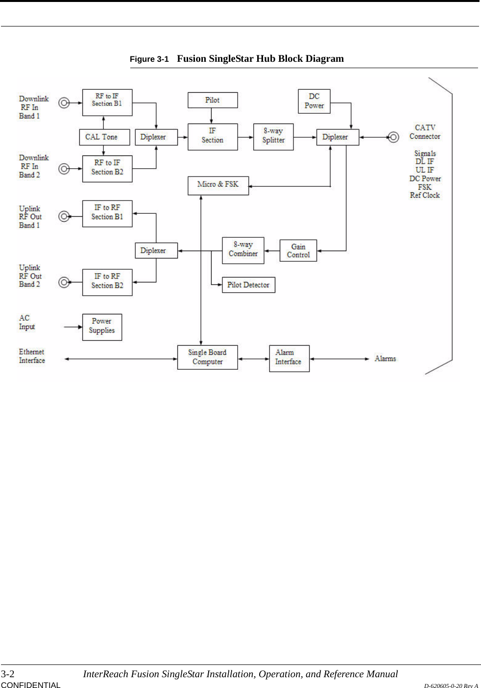
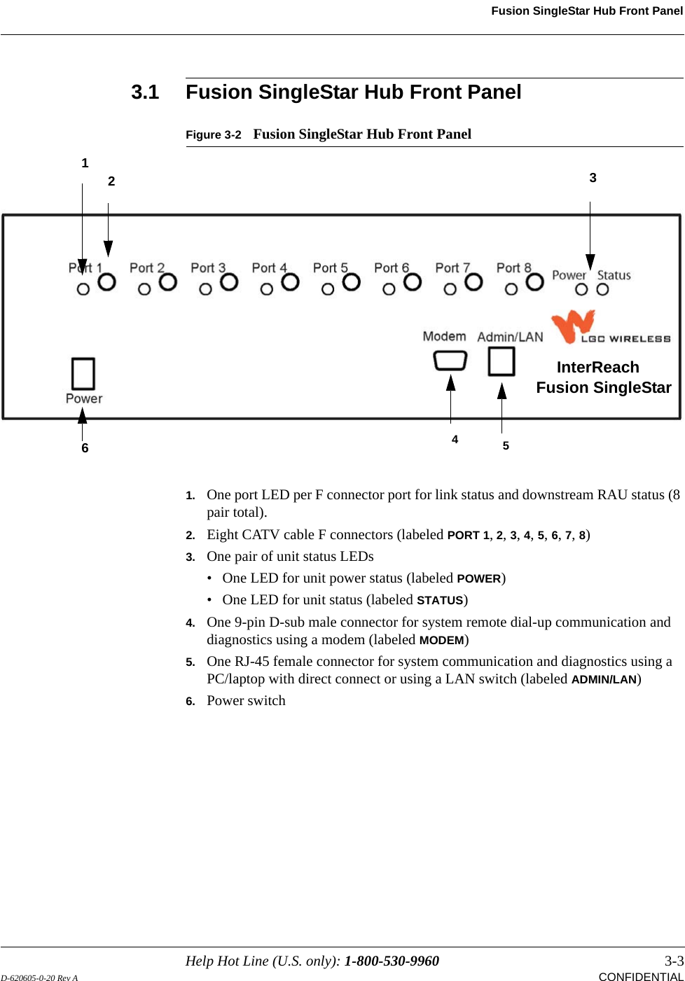
ADC Telecommunications FSN-8519-1 FSN-8519-1 InterReach Fusion Remote Unit User Manual accel
ADC Telecommunications Inc. FSN-8519-1 InterReach Fusion Remote Unit accel
UserManual.wiki
>
ADC Telecommunications
>
FSN-8519-1 User Manual
>
Users Manual
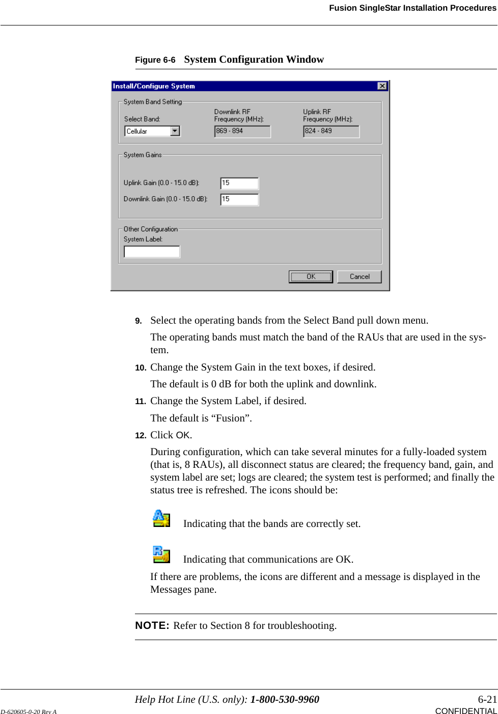
Contents
1.
Users Manual
2.
Manual
Users Manual
Navigation menu
Upload a User Manual
Namespaces
Wiki Guide
HTML
PDF
Info
Views
User Manual
Discussion / Help
Navigation

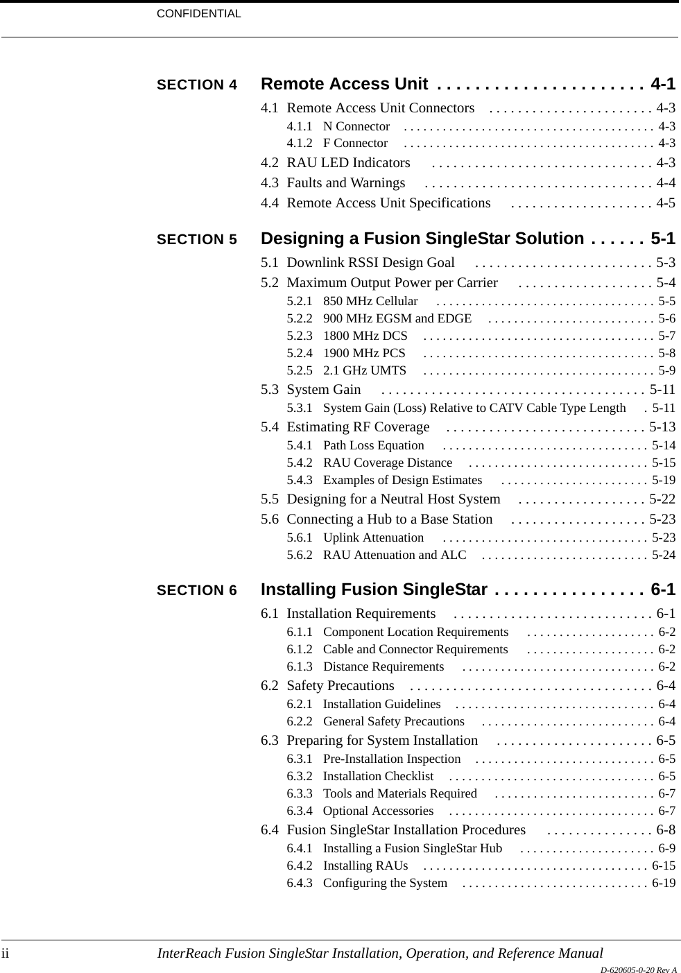
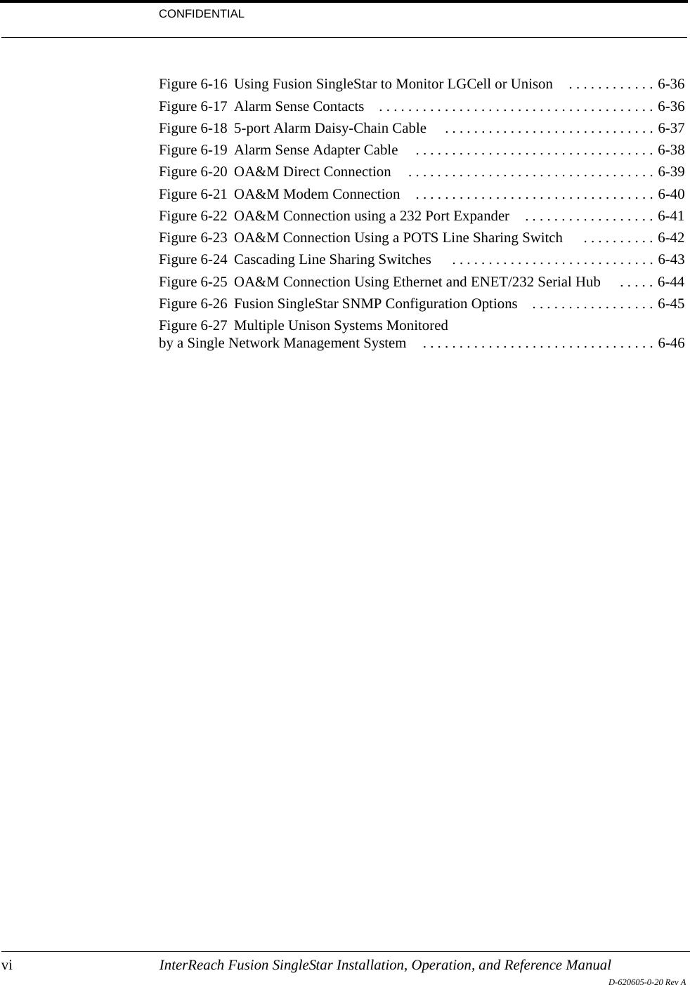
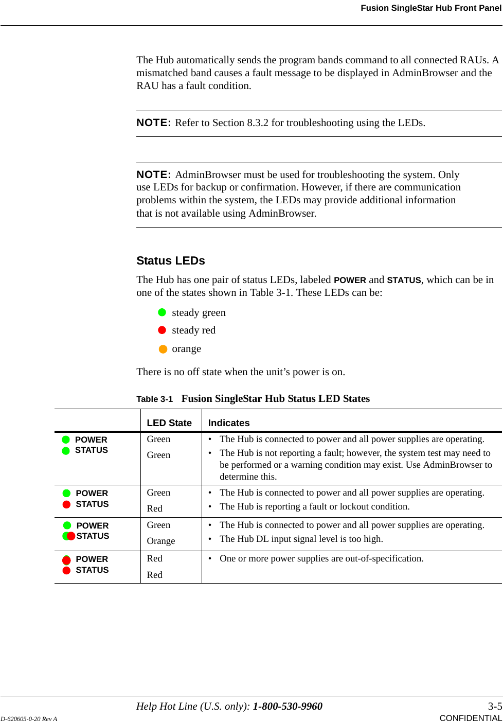
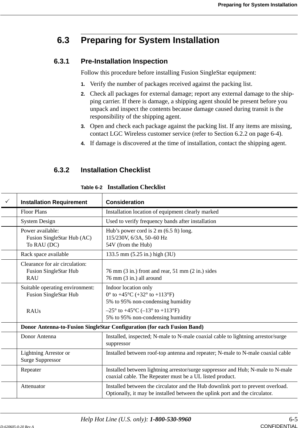
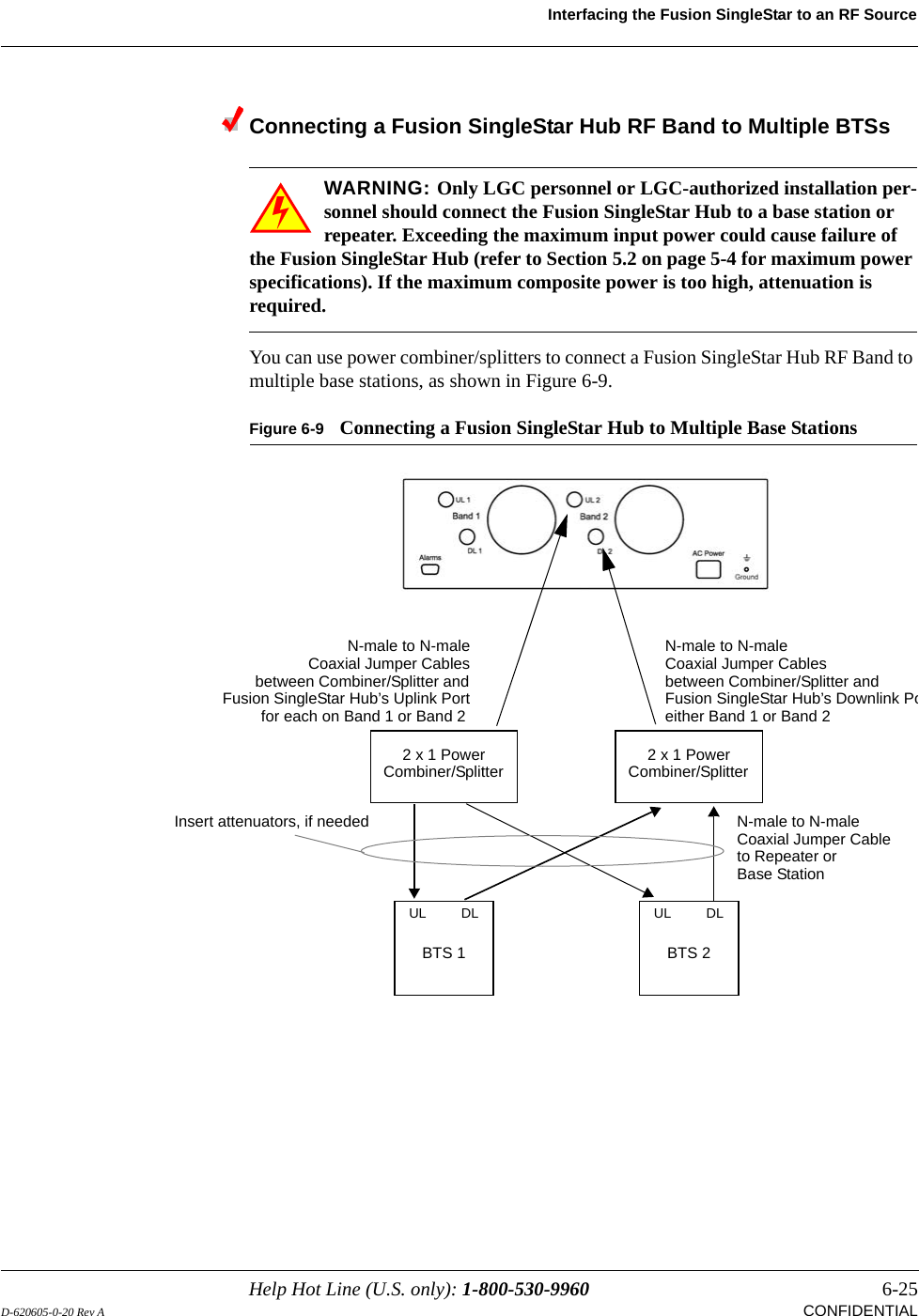
![Fusion SingleStar Hub Front Panel3-6 InterReach Fusion SingleStar Installation, Operation, and Reference ManualCONFIDENTIAL D-620605-0-20 Rev ARJ-45 Port LEDsThe Hub has a port LED, labeled PORT, for each of the eight RJ-45 ports. The port LEDs can be in one of the states shown in Table 3-2. These LEDs can be:offsteady greenflashing red (60 pulses per minute [PPM])Table 3-2 Fusion SingleStar Hub Port LED StatesLED State IndicatesOff • The RAU is not connected.Green• The RAU is connected.• No faults from the RAU.Red (60 PPM)• The RAU was disconnected.• The RAU is not communicating.• The RAU port power is tripped.• 54 VDC is shutdown due to an EH over-temperature condition.Red (Steady)• The RAU is connected.• The RAU is reporting a fault or lockout condition.PORTPORTPORTPORT](https://usermanual.wiki/ADC-Telecommunications/FSN-8519-1.Users-Manual/User-Guide-646373-Page-34.png)
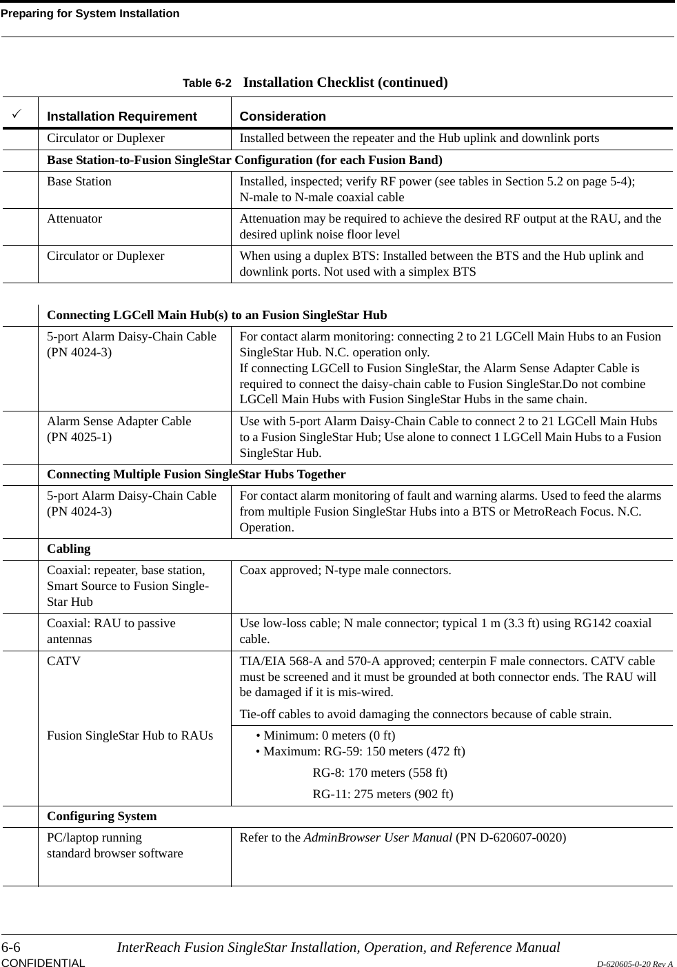
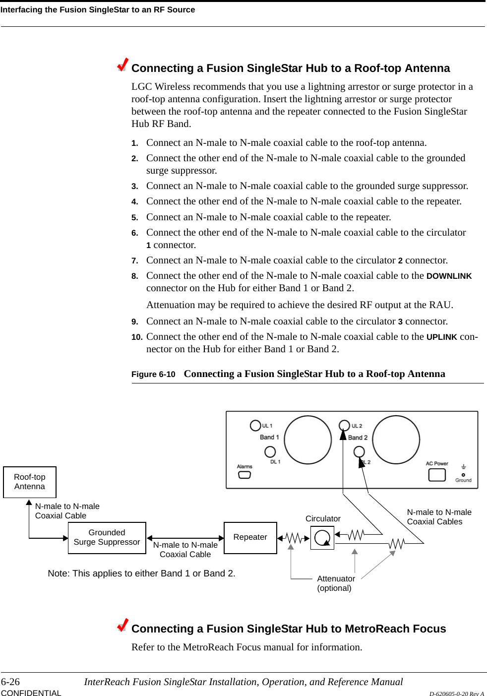
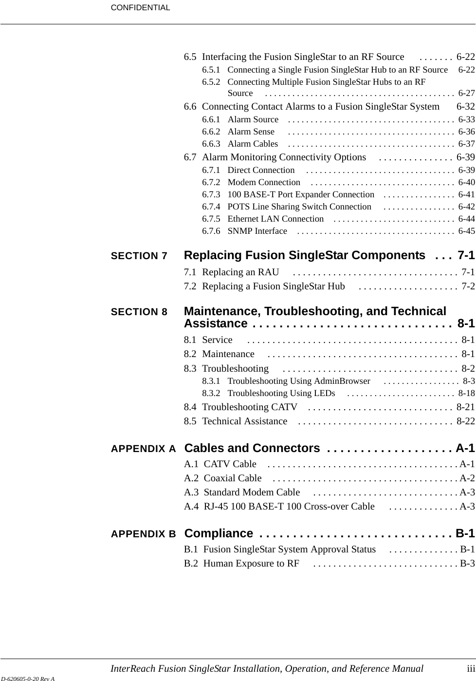
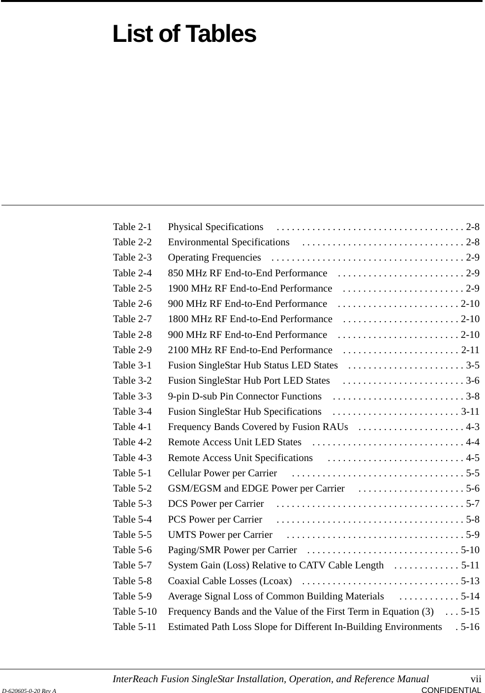
![Help Hot Line (U.S. only): 1-800-530-9960 8-15D-620605-0-20 Rev A CONFIDENTIALTroubleshootingFusion SingleStar Hub Status MessagesTable 8-5 Status Messages Reported by the Fusion SingleStar HubStatus Message Action[MS49]Hub/RAUs report fault condition Check Hub and RAU status.[MS05]Commanded Out-of-Service Command In-service to restore operation.[MS06]Factory special test mode Cycle power to clear test mode.[MS07]System Lockout Check the Hub for faults.[MS08]Unable to perform system test on power upCheck the Hub and RAUs for faults. Re-run system test.[MS09]Auxiliary Board/RAUs report warn-ing conditionCheck the Hub and RAUs for warnings.[MS17]Failed to perform system test (PLL unlock)Unable to perform system end-to-end test. Replace Hub when possible.[MS18]Failed to perform system test (Test tone too high)Unable to perform system end-to-end test. Replace Hub when possible.[MS19]Failed to perform system test (Test tone too low)Unable to perform system end-to-end test. Replace Hub when possible.[MS23]Scheduled System Test complete Scheduled system test competed. (Log entry only.)[MS33]Time Tagged Log Full Use AdminManger to dump and save the Time Tagged Log, then erase it.[MS34]Time of Day not initialized Use AdminBrowser to initialize the time and date.[MS36]Maximum auto recovery limit Maximum number of fault/warning auto-recovery attempts. Use Admin-Browser “Set-in-Service” to allow the MH to attempt additional auto-recovery attempts.[ES04]System test is required Run system test.[ES05]Temperature is high Check fan rotation, air flow blockage, and dust. Check room environmental controls.[ES06]Fan 1 failure Check fan rotation, air flow blockage, dust. Replace the Hub on temperature fault.[ES07]Fan 2 failure Check fan rotation, air flow blockage, dust. Replace the Hub on temperature fault.[ES08]Fan 3 failure Check fan rotation, air flow blockage, dust. Replace the Hub on temperature fault.[ES09]Port 1 UL RF path loss is above the recommended limitCheck the CATV cable, especially on new installations. Use a larger size CATV cable to improve coverage.[ES10]Port 2 UL RF path loss is above the recommended limitCheck the CATV cable, especially on new installations. Use a larger size CATV cable to improve coverage.[ES11]Port 3 UL RF path loss is above the recommended limitCheck the CATV cable, especially on new installations. Use a larger size CATV cable to improve coverage.[ES12]Port 4 UL RF path loss is above the recommended limitCheck the CATV cable, especially on new installations. Use a larger size CATV cable to improve coverage.](https://usermanual.wiki/ADC-Telecommunications/FSN-8519-1.Users-Manual/User-Guide-646373-Page-139.png)
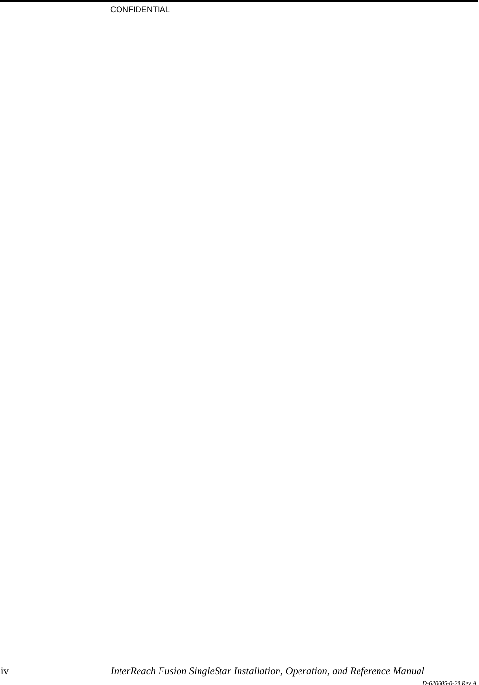
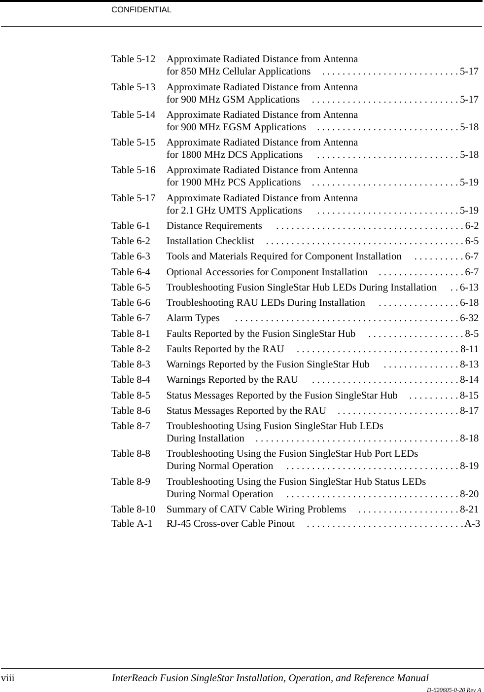
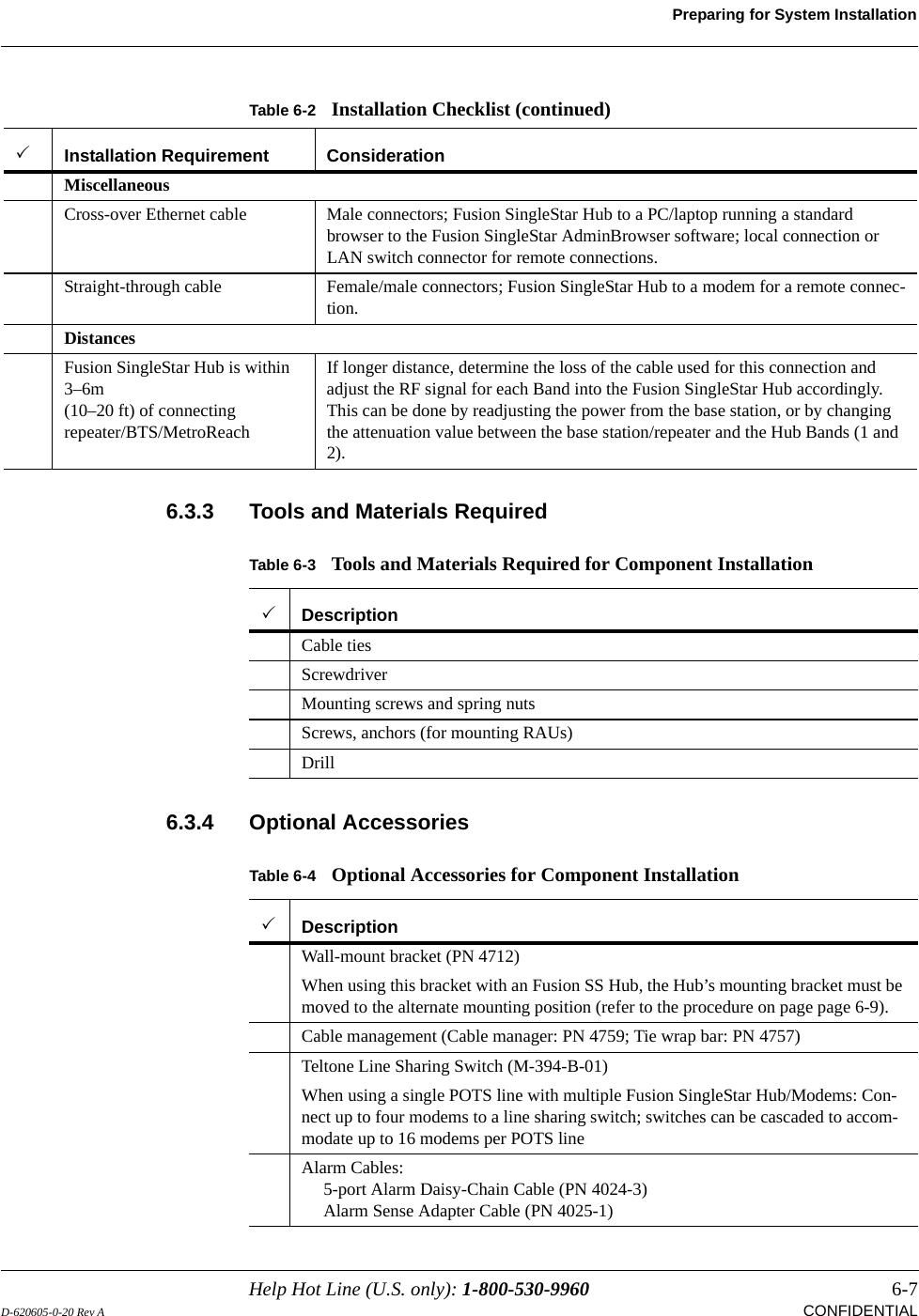
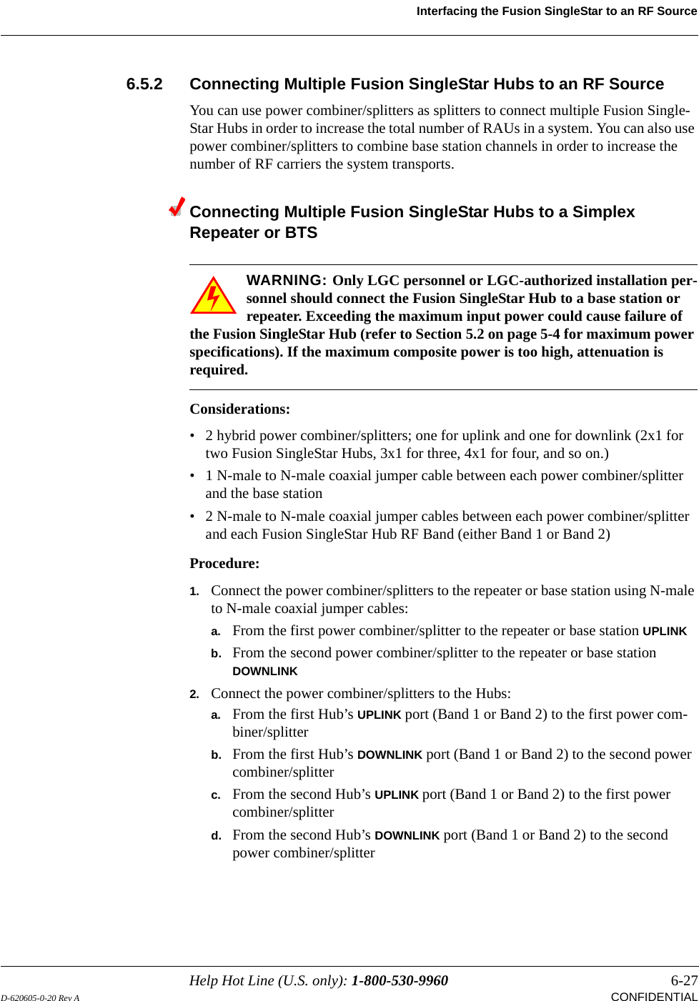
![Troubleshooting8-16 InterReach Fusion SS Installation, Operation, and Reference ManualCONFIDENTIAL D-620605-0-20 Rev A[ES13]Port 5 UL RF path loss is above the recommended limitCheck the CATV cable, especially on new installations. Use a larger size CATV cable to improve coverage.[ES14]Port 6 UL RF path loss is above the recommended limitCheck the CATV cable, especially on new installations.Use a larger size CATV cable to improve coverage.[ES15]Port 7 UL RF path loss is above the recommended limitCheck the CATV cable, especially on new installations. Use a larger size CATV cable to improve coverage.[ES16]Port 8 UL RF path loss is above the recommended limitCheck the CATV cable, especially on new installations. Use a larger size CATV cable to improve coverage.[ES17]Commanded Out-of-Service Command In-service to restore operation.[ES18]External fault lockout Check the Hub for faults.[ES20]Factory special test mode Cycle power to clear test mode[ES25]Port 1 DL RF path too low Try another port. If status persists, replace the Hub. Otherwise, flag the previ-ous port as unusable and replace the Hub when possible.[ES25]Port 2 DL RF path too low Try another port. If status persists, replace the Hub. Otherwise, flag the previ-ous port as unusable and replace the Hub when possible.[ES25]Port 3 DL RF path too low Try another port. If status persists, replace the Hub. Otherwise, flag the previ-ous port as unusable and replace the Hub when possible.[ES25]Port 4 DL RF path too low Try another port. If status persists, replace the Hub. Otherwise, flag the previ-ous port as unusable and replace the Hub when possible.[ES25]Port 5 DL RF path too low Try another port. If status persists, replace the Hub. Otherwise, flag the previ-ous port as unusable and replace the Hub when possible.[ES25]Port 6 DL RF path too low Try another port. If status persists, replace the Hub. Otherwise, flag the previ-ous port as unusable and replace the Hub when possible.[ES25]Port 7 DL RF path too low Try another port. If status persists, replace the Hub. Otherwise, flag the previ-ous port as unusable and replace the Hub when possible.[ES25]Port 8 DL RF path too low Try another port. If status persists, replace the Hub. Otherwise, flag the previ-ous port as unusable and replace the Hub when possible.](https://usermanual.wiki/ADC-Telecommunications/FSN-8519-1.Users-Manual/User-Guide-646373-Page-140.png)
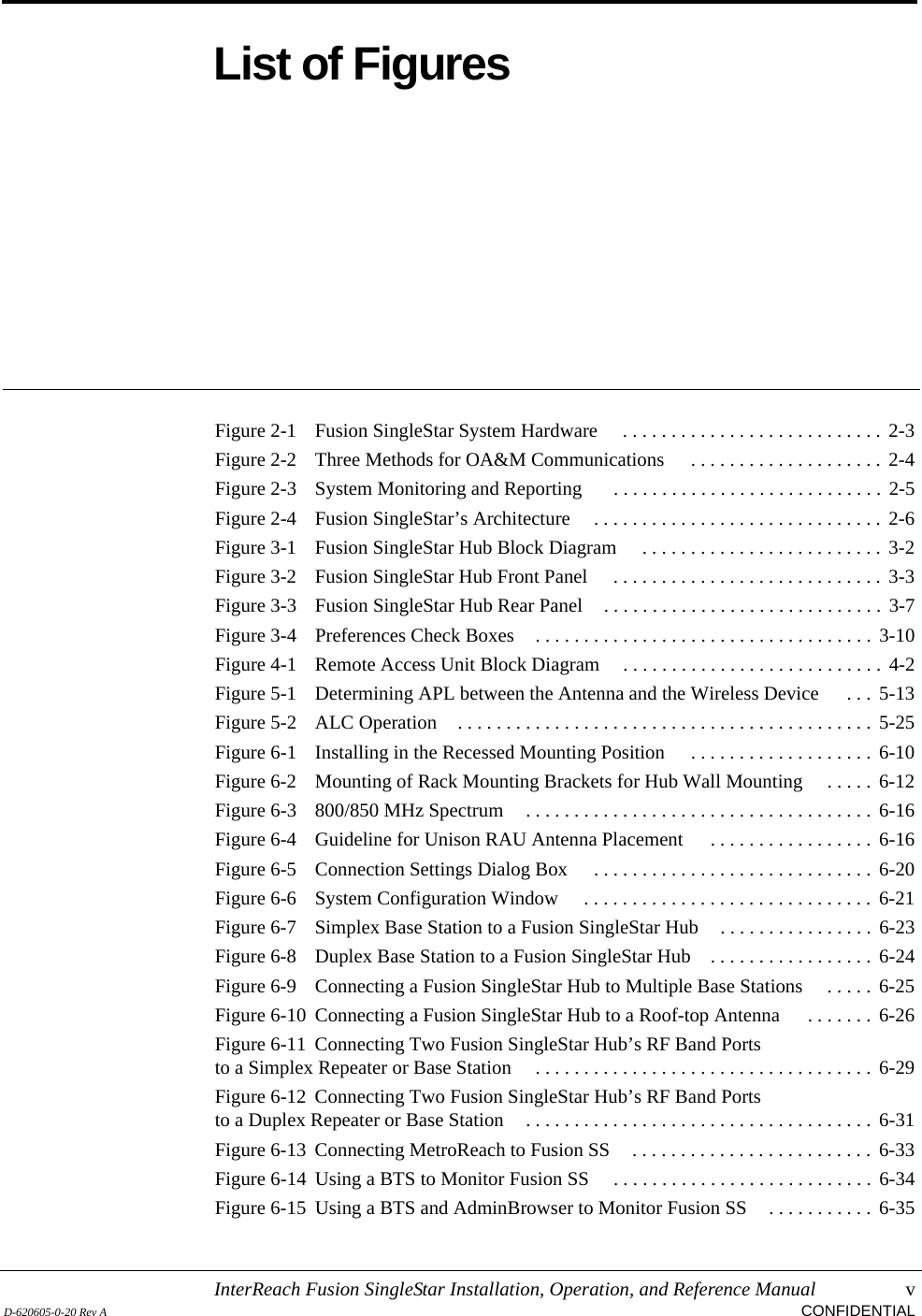
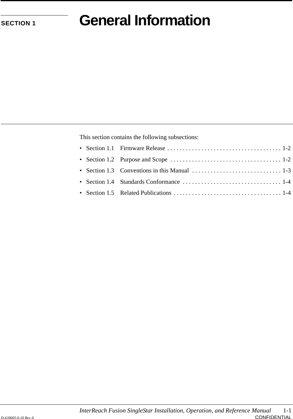
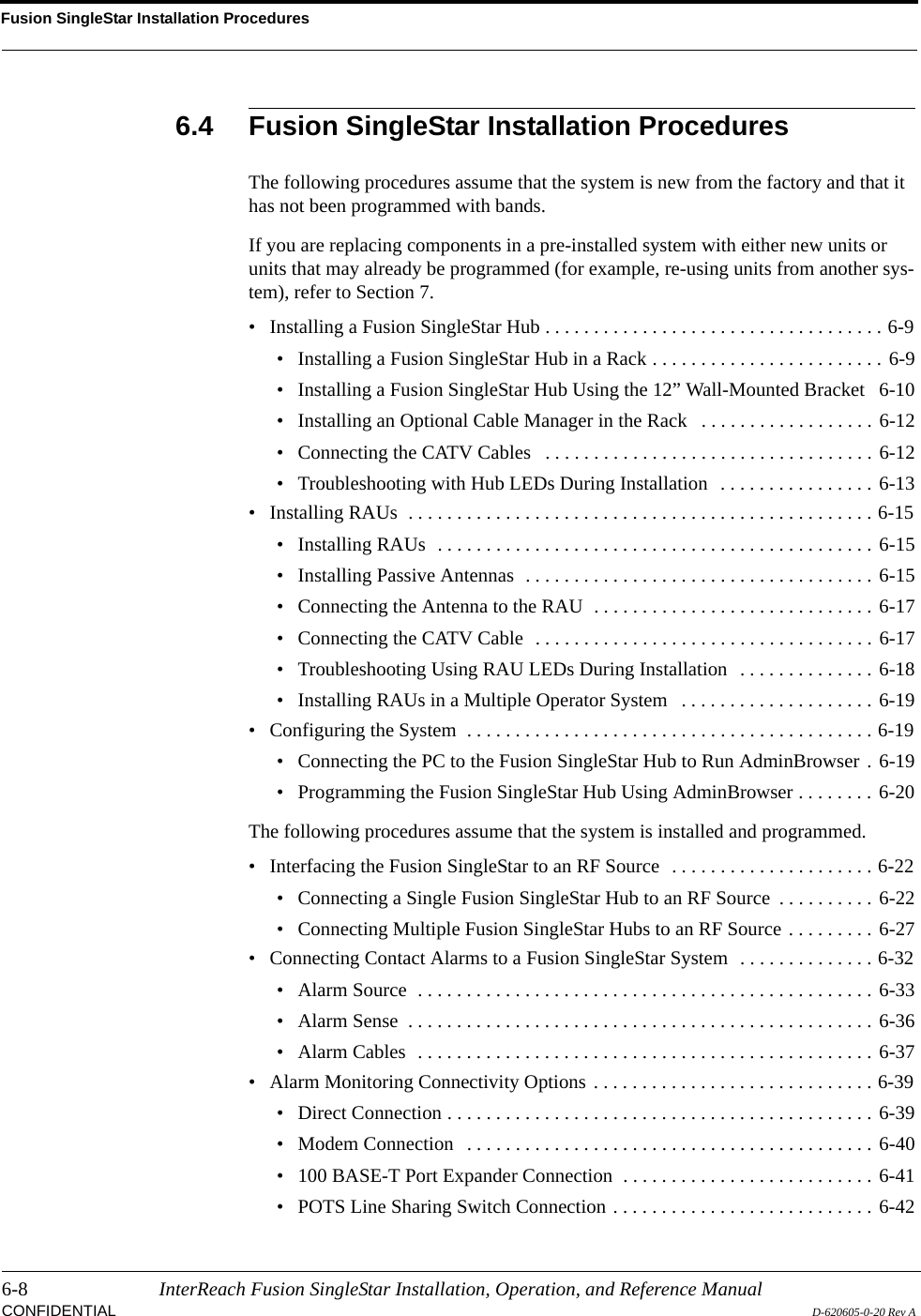
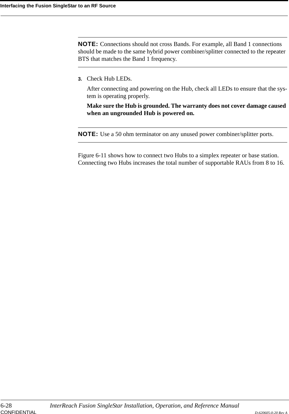
![Help Hot Line (U.S. only): 1-800-530-9960 8-17D-620605-0-20 Rev A CONFIDENTIALTroubleshootingRemote Access Unit Status MessagesTable 8-6 Status Messages Reported by the RAUStatus Message Action[RS01]Temperature is high Check for proper installation. Check environmental controls, move the RAU to a cooler environment.[RS02]DC voltage is low Check the CATV cable. Replace the RAU when possible.[RS03]Power amplifier is failing Replace the RAU when possible.[RS05]The cable loss between the EH/Fusion SingleStar Hub and RAU is above the recommended limitCheck the CATV cable for shorts/opens, especially on new install. If the status is common to more than one RAU, replace the Expansion/Fusion SingleStar Hub when possible. Use a larger size CATV cable to improve coverage. [RS06]System test required Run the system test.[RS07]Antenna disconnected Check the antenna connection and rerun the system test. (Antenna disconnect reporting level is user selectable between warnings and status.)[RS09]Commanded Out-of-Service Command In-service to restore operation.[RS10]External fault lockout Check the Hub for faults.[RS11]Internal fault lockout Check the RAU faults. The RAU is Out-of-Service.[RS13]DC Power supplied by the EH/Fusion SingleStar Hub is too highCheck the CATV cable for shorts/opens, especially on new installations. If sta-tus common to more than one RAU, replace the Expansion/Fusion SingleStar Hub when possible. Try another port. If no status is reported, flag the previous port as unusable and replace the Hub when possible. Otherwise, replace the RAU when possible.[RS14]Potential failure in the UL RF path Unable to complete system end-to-end test. Replace the RAU when possible[RS15]Potential failure in the DL RF path Unable to complete system end-to-end test. Check the RAU termination at SMA connector and re-test. Replace the RAU if no Hub alarms.](https://usermanual.wiki/ADC-Telecommunications/FSN-8519-1.Users-Manual/User-Guide-646373-Page-141.png)