ADC Telecommunications FSN-8519-1 FSN-8519-1 InterReach Fusion Remote Unit User Manual accel
ADC Telecommunications Inc. FSN-8519-1 InterReach Fusion Remote Unit accel
Contents
- 1. Users Manual
- 2. Manual
Users Manual
D-620605-0-20
Rev A
Installation, Operation, and Reference Manual
InterReach FusionTM SingleStar
®

D-620605-0-20 Help Hot Line (U.S. only): 1-800-530-9960
Rev A CONFIDENTIAL

D-620605-0-20 Help Hot Line (U.S. only): 1-800-530-9960
Rev A CONFIDENTIAL
This manual is produced for use by LGC Wireless personnel, licensees, and customers. The
information contained herein is the property of LGC Wireless. No part of this document
may be reproduced or transmitted in any form or by any means, electronic or mechanical,
for any purpose, without the express written permission of LGC Wireless.
LGC Wireless reserves the right to make changes, without notice, to the specifications and
materials contained herein, and shall not be responsible for any damages caused by reliance
on the material as presented, including, but not limited to, typographical and listing errors.
Your comments are welcome – they help us improve our products and documentation.
Please address your comments to LGC Wireless, Inc. corporate headquarters in San Jose,
California:
Address 2540 Junction Avenue
San Jose, California
95134-1902 USA
Attn: Marketing Dept.
Phone 1-408-952-2400
Fax 1-408-952-2410
Help Hot Line 1-800-530-9960 (U.S. only)
+1-408-952-2400 (International)
Web Address http://www.lgcwireless.com
e-mail info@lgcwireless.com
service@lgcwireless.com
Copyright © 2006 by LGC Wireless, Inc. Printed in USA. All rights reserved.
Trademarks
All trademarks identified by ™ or ® are trademarks or registered trademarks of LGC
Wireless, Inc. All other trademarks belong to their respective owners.

InterReach Fusion SingleStar Installation, Operation, and Reference Manual
CONFIDENTIAL D-620605-0-20 Rev D
Limited Warranty
Seller warrants articles of its manufacture against defective materials or workmanship for a
period of one year from the date of shipment to Purchaser, except as provided in any warranty
applicable to Purchaser on or in the package containing the Goods (which warranty takes
precedence over the following warranty). The liability of Seller under the foregoing warranty
is limited, at Seller’s option, solely to repair or replacement with equivalent Goods, or an
appropriate adjustment not to exceed the sales price to Purchaser, provided that (a) Seller is
notified in writing by Purchaser, within the one year warranty period, promptly upon
discovery of defects, with a detailed description of such defects, (b) Purchaser has obtained a
Return Materials Authorization (RMA) from Seller, which RMA Seller agrees to provide
Purchaser promptly upon request, (c) the defective Goods are returned to Seller,
transportation and other applicable charges prepaid by the Purchaser, and (d) Seller’s
examination of such Goods discloses to its reasonable satisfaction that defects were not
caused by negligence, misuse, improper installation, improper maintenance, accident or
unauthorized repair or alteration or any other cause outside the scope of Purchaser’s warranty
made hereunder. Notwithstanding the foregoing, Seller shall have the option to repair any
defective Goods at Purchaser’s facility. The original warranty period for any Goods that have
been repaired or replaced by seller will not thereby be extended. In addition, all sales will be
subject to standard terms and conditions on the sales contract.
Licensed Operators
LGC Wireless’ equipment is designed to operate in the licensed frequency bands of mobile,
cellular, and PCS operators. In the USA, the EU, and most countries this equipment may
only be used by the licensee, his authorized agents or those with written authorization to do
so. Similarly, unauthorized use is illegal, and subjects the owner to the corresponding legal
sanctions of the national jurisdiction involved. Ownership of LGC Wireless equipment
carries no automatic right of use.

InterReach Fusion SingleStar Installation, Operation, and Reference Manual i
D-620605-0-20 Rev A CONFIDENTIAL
Table of Contents
SECTION 1 General Information . . . . . . . . . . . . . . . . . . . . . . 1-1
1.1 Firmware Release . . . . . . . . . . . . . . . . . . . . . . . . . . . . . . . . . . 1-2
1.2 Purpose and Scope . . . . . . . . . . . . . . . . . . . . . . . . . . . . . . . . . 1-2
1.3 Conventions in this Manual . . . . . . . . . . . . . . . . . . . . . . . . . . 1-3
1.4 Standards Conformance . . . . . . . . . . . . . . . . . . . . . . . . . . . . . 1-4
1.5 Related Publications . . . . . . . . . . . . . . . . . . . . . . . . . . . . . . . . 1-4
SECTION 2 InterReach Fusion SingleStar
System Description . . . . . . . . . . . . . . . . . . . . . . 2-1
2.1 System Hardware Description . . . . . . . . . . . . . . . . . . . . . . . . 2-3
2.2 System OA&M Capabilities Overview . . . . . . . . . . . . . . . . . 2-4
2.2.1 System Monitoring and Reporting . . . . . . . . . . . . . . . . . . . . . 2-5
2.2.2 Using Alarm Contact Closures . . . . . . . . . . . . . . . . . . . . . . . . 2-5
2.3 System Connectivity . . . . . . . . . . . . . . . . . . . . . . . . . . . . . . . . 2-6
2.4 System Operation . . . . . . . . . . . . . . . . . . . . . . . . . . . . . . . . . . 2-7
2.5 System Specifications . . . . . . . . . . . . . . . . . . . . . . . . . . . . . . . 2-8
2.5.1 RF End-to-End Performance . . . . . . . . . . . . . . . . . . . . . . . . . . 2-9
SECTION 3 Fusion SingleStar Hub . . . . . . . . . . . . . . . . . . . . 3-1
3.1 Fusion SingleStar Hub Front Panel . . . . . . . . . . . . . . . . . . . . 3-3
3.1.1 F Connectors . . . . . . . . . . . . . . . . . . . . . . . . . . . . . . . . . . . . . . 3-4
3.1.2 Communications RS-232 Serial Connector . . . . . . . . . . . . . . 3-4
3.1.3 Hub LED Indicators . . . . . . . . . . . . . . . . . . . . . . . . . . . . . . . . 3-4
3.2 Fusion SingleStar Hub Rear Panel . . . . . . . . . . . . . . . . . . . . . 3-7
3.2.1 Fusion SingleStar Hub Rear Panel Connectors . . . . . . . . . . . . 3-8
3.3 Faults, Warnings, and Status Messages . . . . . . . . . . . . . . . . . 3-9
3.3.1 Description . . . . . . . . . . . . . . . . . . . . . . . . . . . . . . . . . . . . . . . 3-9
3.3.2 View Preference . . . . . . . . . . . . . . . . . . . . . . . . . . . . . . . . . . . 3-9
3.4 Fusion SingleStar Hub Specifications . . . . . . . . . . . . . . . . . 3-11

CONFIDENTIAL
ii InterReach Fusion SingleStar Installation, Operation, and Reference Manual
D-620605-0-20 Rev A
SECTION 4 Remote Access Unit . . . . . . . . . . . . . . . . . . . . . . 4-1
4.1 Remote Access Unit Connectors . . . . . . . . . . . . . . . . . . . . . . . 4-3
4.1.1 N Connector . . . . . . . . . . . . . . . . . . . . . . . . . . . . . . . . . . . . . . . 4-3
4.1.2 F Connector . . . . . . . . . . . . . . . . . . . . . . . . . . . . . . . . . . . . . . . 4-3
4.2 RAU LED Indicators . . . . . . . . . . . . . . . . . . . . . . . . . . . . . . . 4-3
4.3 Faults and Warnings . . . . . . . . . . . . . . . . . . . . . . . . . . . . . . . . 4-4
4.4 Remote Access Unit Specifications . . . . . . . . . . . . . . . . . . . . 4-5
SECTION 5 Designing a Fusion SingleStar Solution . . . . . . 5-1
5.1 Downlink RSSI Design Goal . . . . . . . . . . . . . . . . . . . . . . . . . 5-3
5.2 Maximum Output Power per Carrier . . . . . . . . . . . . . . . . . . . 5-4
5.2.1 850 MHz Cellular . . . . . . . . . . . . . . . . . . . . . . . . . . . . . . . . . . 5-5
5.2.2 900 MHz EGSM and EDGE . . . . . . . . . . . . . . . . . . . . . . . . . . 5-6
5.2.3 1800 MHz DCS . . . . . . . . . . . . . . . . . . . . . . . . . . . . . . . . . . . . 5-7
5.2.4 1900 MHz PCS . . . . . . . . . . . . . . . . . . . . . . . . . . . . . . . . . . . . 5-8
5.2.5 2.1 GHz UMTS . . . . . . . . . . . . . . . . . . . . . . . . . . . . . . . . . . . . 5-9
5.3 System Gain . . . . . . . . . . . . . . . . . . . . . . . . . . . . . . . . . . . . . 5-11
5.3.1 System Gain (Loss) Relative to CATV Cable Type Length . 5-11
5.4 Estimating RF Coverage . . . . . . . . . . . . . . . . . . . . . . . . . . . . 5-13
5.4.1 Path Loss Equation . . . . . . . . . . . . . . . . . . . . . . . . . . . . . . . . 5-14
5.4.2 RAU Coverage Distance . . . . . . . . . . . . . . . . . . . . . . . . . . . . 5-15
5.4.3 Examples of Design Estimates . . . . . . . . . . . . . . . . . . . . . . . 5-19
5.5 Designing for a Neutral Host System . . . . . . . . . . . . . . . . . . 5-22
5.6 Connecting a Hub to a Base Station . . . . . . . . . . . . . . . . . . . 5-23
5.6.1 Uplink Attenuation . . . . . . . . . . . . . . . . . . . . . . . . . . . . . . . . 5-23
5.6.2 RAU Attenuation and ALC . . . . . . . . . . . . . . . . . . . . . . . . . . 5-24
SECTION 6 Installing Fusion SingleStar . . . . . . . . . . . . . . . . 6-1
6.1 Installation Requirements . . . . . . . . . . . . . . . . . . . . . . . . . . . . 6-1
6.1.1 Component Location Requirements . . . . . . . . . . . . . . . . . . . . 6-2
6.1.2 Cable and Connector Requirements . . . . . . . . . . . . . . . . . . . . 6-2
6.1.3 Distance Requirements . . . . . . . . . . . . . . . . . . . . . . . . . . . . . . 6-2
6.2 Safety Precautions . . . . . . . . . . . . . . . . . . . . . . . . . . . . . . . . . . 6-4
6.2.1 Installation Guidelines . . . . . . . . . . . . . . . . . . . . . . . . . . . . . . . 6-4
6.2.2 General Safety Precautions . . . . . . . . . . . . . . . . . . . . . . . . . . . 6-4
6.3 Preparing for System Installation . . . . . . . . . . . . . . . . . . . . . . 6-5
6.3.1 Pre-Installation Inspection . . . . . . . . . . . . . . . . . . . . . . . . . . . . 6-5
6.3.2 Installation Checklist . . . . . . . . . . . . . . . . . . . . . . . . . . . . . . . . 6-5
6.3.3 Tools and Materials Required . . . . . . . . . . . . . . . . . . . . . . . . . 6-7
6.3.4 Optional Accessories . . . . . . . . . . . . . . . . . . . . . . . . . . . . . . . . 6-7
6.4 Fusion SingleStar Installation Procedures . . . . . . . . . . . . . . . 6-8
6.4.1 Installing a Fusion SingleStar Hub . . . . . . . . . . . . . . . . . . . . . 6-9
6.4.2 Installing RAUs . . . . . . . . . . . . . . . . . . . . . . . . . . . . . . . . . . . 6-15
6.4.3 Configuring the System . . . . . . . . . . . . . . . . . . . . . . . . . . . . . 6-19

CONFIDENTIAL
InterReach Fusion SingleStar Installation, Operation, and Reference Manual iii
D-620605-0-20 Rev A
6.5 Interfacing the Fusion SingleStar to an RF Source . . . . . . . 6-22
6.5.1 Connecting a Single Fusion SingleStar Hub to an RF Source 6-22
6.5.2 Connecting Multiple Fusion SingleStar Hubs to an RF
Source . . . . . . . . . . . . . . . . . . . . . . . . . . . . . . . . . . . . . . . . . . 6-27
6.6 Connecting Contact Alarms to a Fusion SingleStar System 6-32
6.6.1 Alarm Source . . . . . . . . . . . . . . . . . . . . . . . . . . . . . . . . . . . . . 6-33
6.6.2 Alarm Sense . . . . . . . . . . . . . . . . . . . . . . . . . . . . . . . . . . . . . 6-36
6.6.3 Alarm Cables . . . . . . . . . . . . . . . . . . . . . . . . . . . . . . . . . . . . . 6-37
6.7 Alarm Monitoring Connectivity Options . . . . . . . . . . . . . . . 6-39
6.7.1 Direct Connection . . . . . . . . . . . . . . . . . . . . . . . . . . . . . . . . . 6-39
6.7.2 Modem Connection . . . . . . . . . . . . . . . . . . . . . . . . . . . . . . . . 6-40
6.7.3 100 BASE-T Port Expander Connection . . . . . . . . . . . . . . . . 6-41
6.7.4 POTS Line Sharing Switch Connection . . . . . . . . . . . . . . . . 6-42
6.7.5 Ethernet LAN Connection . . . . . . . . . . . . . . . . . . . . . . . . . . . 6-44
6.7.6 SNMP Interface . . . . . . . . . . . . . . . . . . . . . . . . . . . . . . . . . . . 6-45
SECTION 7 Replacing Fusion SingleStar Components . . . 7-1
7.1 Replacing an RAU . . . . . . . . . . . . . . . . . . . . . . . . . . . . . . . . . 7-1
7.2 Replacing a Fusion SingleStar Hub . . . . . . . . . . . . . . . . . . . . 7-2
SECTION 8 Maintenance, Troubleshooting, and Technical
Assistance . . . . . . . . . . . . . . . . . . . . . . . . . . . . . . 8-1
8.1 Service . . . . . . . . . . . . . . . . . . . . . . . . . . . . . . . . . . . . . . . . . . 8-1
8.2 Maintenance . . . . . . . . . . . . . . . . . . . . . . . . . . . . . . . . . . . . . . 8-1
8.3 Troubleshooting . . . . . . . . . . . . . . . . . . . . . . . . . . . . . . . . . . . 8-2
8.3.1 Troubleshooting Using AdminBrowser . . . . . . . . . . . . . . . . . 8-3
8.3.2 Troubleshooting Using LEDs . . . . . . . . . . . . . . . . . . . . . . . . 8-18
8.4 Troubleshooting CATV . . . . . . . . . . . . . . . . . . . . . . . . . . . . . 8-21
8.5 Technical Assistance . . . . . . . . . . . . . . . . . . . . . . . . . . . . . . . 8-22
APPENDIX A Cables and Connectors . . . . . . . . . . . . . . . . . . . A-1
A.1 CATV Cable . . . . . . . . . . . . . . . . . . . . . . . . . . . . . . . . . . . . . . A-1
A.2 Coaxial Cable . . . . . . . . . . . . . . . . . . . . . . . . . . . . . . . . . . . . . A-2
A.3 Standard Modem Cable . . . . . . . . . . . . . . . . . . . . . . . . . . . . . A-3
A.4 RJ-45 100 BASE-T 100 Cross-over Cable . . . . . . . . . . . . . . A-3
APPENDIX B Compliance . . . . . . . . . . . . . . . . . . . . . . . . . . . . . B-1
B.1 Fusion SingleStar System Approval Status . . . . . . . . . . . . . . B-1
B.2 Human Exposure to RF . . . . . . . . . . . . . . . . . . . . . . . . . . . . . B-3

CONFIDENTIAL
iv InterReach Fusion SingleStar Installation, Operation, and Reference Manual
D-620605-0-20 Rev A

InterReach Fusion SingleStar Installation, Operation, and Reference Manual v
D-620605-0-20 Rev A CONFIDENTIAL
List of Figures
Figure 2-1 Fusion SingleStar System Hardware . . . . . . . . . . . . . . . . . . . . . . . . . . . 2-3
Figure 2-2 Three Methods for OA&M Communications . . . . . . . . . . . . . . . . . . . . 2-4
Figure 2-3 System Monitoring and Reporting . . . . . . . . . . . . . . . . . . . . . . . . . . . . 2-5
Figure 2-4 Fusion SingleStar’s Architecture . . . . . . . . . . . . . . . . . . . . . . . . . . . . . . 2-6
Figure 3-1 Fusion SingleStar Hub Block Diagram . . . . . . . . . . . . . . . . . . . . . . . . . 3-2
Figure 3-2 Fusion SingleStar Hub Front Panel . . . . . . . . . . . . . . . . . . . . . . . . . . . . 3-3
Figure 3-3 Fusion SingleStar Hub Rear Panel . . . . . . . . . . . . . . . . . . . . . . . . . . . . . 3-7
Figure 3-4 Preferences Check Boxes . . . . . . . . . . . . . . . . . . . . . . . . . . . . . . . . . . . 3-10
Figure 4-1 Remote Access Unit Block Diagram . . . . . . . . . . . . . . . . . . . . . . . . . . . 4-2
Figure 5-1 Determining APL between the Antenna and the Wireless Device . . . 5-13
Figure 5-2 ALC Operation . . . . . . . . . . . . . . . . . . . . . . . . . . . . . . . . . . . . . . . . . . . 5-25
Figure 6-1 Installing in the Recessed Mounting Position . . . . . . . . . . . . . . . . . . . 6-10
Figure 6-2 Mounting of Rack Mounting Brackets for Hub Wall Mounting . . . . . 6-12
Figure 6-3 800/850 MHz Spectrum . . . . . . . . . . . . . . . . . . . . . . . . . . . . . . . . . . . . 6-16
Figure 6-4 Guideline for Unison RAU Antenna Placement . . . . . . . . . . . . . . . . . 6-16
Figure 6-5 Connection Settings Dialog Box . . . . . . . . . . . . . . . . . . . . . . . . . . . . . 6-20
Figure 6-6 System Configuration Window . . . . . . . . . . . . . . . . . . . . . . . . . . . . . . 6-21
Figure 6-7 Simplex Base Station to a Fusion SingleStar Hub . . . . . . . . . . . . . . . . 6-23
Figure 6-8 Duplex Base Station to a Fusion SingleStar Hub . . . . . . . . . . . . . . . . . 6-24
Figure 6-9 Connecting a Fusion SingleStar Hub to Multiple Base Stations . . . . . 6-25
Figure 6-10 Connecting a Fusion SingleStar Hub to a Roof-top Antenna . . . . . . . 6-26
Figure 6-11 Connecting Two Fusion SingleStar Hub’s RF Band Ports
to a Simplex Repeater or Base Station . . . . . . . . . . . . . . . . . . . . . . . . . . . . . . . . . . . 6-29
Figure 6-12 Connecting Two Fusion SingleStar Hub’s RF Band Ports
to a Duplex Repeater or Base Station . . . . . . . . . . . . . . . . . . . . . . . . . . . . . . . . . . . . 6-31
Figure 6-13 Connecting MetroReach to Fusion SS . . . . . . . . . . . . . . . . . . . . . . . . . 6-33
Figure 6-14 Using a BTS to Monitor Fusion SS . . . . . . . . . . . . . . . . . . . . . . . . . . . 6-34
Figure 6-15 Using a BTS and AdminBrowser to Monitor Fusion SS . . . . . . . . . . . 6-35

CONFIDENTIAL
vi InterReach Fusion SingleStar Installation, Operation, and Reference Manual
D-620605-0-20 Rev A
Figure 6-16 Using Fusion SingleStar to Monitor LGCell or Unison . . . . . . . . . . . . 6-36
Figure 6-17 Alarm Sense Contacts . . . . . . . . . . . . . . . . . . . . . . . . . . . . . . . . . . . . . . 6-36
Figure 6-18 5-port Alarm Daisy-Chain Cable . . . . . . . . . . . . . . . . . . . . . . . . . . . . . 6-37
Figure 6-19 Alarm Sense Adapter Cable . . . . . . . . . . . . . . . . . . . . . . . . . . . . . . . . . 6-38
Figure 6-20 OA&M Direct Connection . . . . . . . . . . . . . . . . . . . . . . . . . . . . . . . . . . 6-39
Figure 6-21 OA&M Modem Connection . . . . . . . . . . . . . . . . . . . . . . . . . . . . . . . . . 6-40
Figure 6-22 OA&M Connection using a 232 Port Expander . . . . . . . . . . . . . . . . . . 6-41
Figure 6-23 OA&M Connection Using a POTS Line Sharing Switch . . . . . . . . . . 6-42
Figure 6-24 Cascading Line Sharing Switches . . . . . . . . . . . . . . . . . . . . . . . . . . . . 6-43
Figure 6-25 OA&M Connection Using Ethernet and ENET/232 Serial Hub . . . . . 6-44
Figure 6-26 Fusion SingleStar SNMP Configuration Options . . . . . . . . . . . . . . . . . 6-45
Figure 6-27 Multiple Unison Systems Monitored
by a Single Network Management System . . . . . . . . . . . . . . . . . . . . . . . . . . . . . . . . 6-46

InterReach Fusion SingleStar Installation, Operation, and Reference Manual vii
D-620605-0-20 Rev A CONFIDENTIAL
List of Tables
Table 2-1 Physical Specifications . . . . . . . . . . . . . . . . . . . . . . . . . . . . . . . . . . . . . 2-8
Table 2-2 Environmental Specifications . . . . . . . . . . . . . . . . . . . . . . . . . . . . . . . . 2-8
Table 2-3 Operating Frequencies . . . . . . . . . . . . . . . . . . . . . . . . . . . . . . . . . . . . . . 2-9
Table 2-4 850 MHz RF End-to-End Performance . . . . . . . . . . . . . . . . . . . . . . . . . 2-9
Table 2-5 1900 MHz RF End-to-End Performance . . . . . . . . . . . . . . . . . . . . . . . . 2-9
Table 2-6 900 MHz RF End-to-End Performance . . . . . . . . . . . . . . . . . . . . . . . . 2-10
Table 2-7 1800 MHz RF End-to-End Performance . . . . . . . . . . . . . . . . . . . . . . . 2-10
Table 2-8 900 MHz RF End-to-End Performance . . . . . . . . . . . . . . . . . . . . . . . . 2-10
Table 2-9 2100 MHz RF End-to-End Performance . . . . . . . . . . . . . . . . . . . . . . . 2-11
Table 3-1 Fusion SingleStar Hub Status LED States . . . . . . . . . . . . . . . . . . . . . . . 3-5
Table 3-2 Fusion SingleStar Hub Port LED States . . . . . . . . . . . . . . . . . . . . . . . . 3-6
Table 3-3 9-pin D-sub Pin Connector Functions . . . . . . . . . . . . . . . . . . . . . . . . . . 3-8
Table 3-4 Fusion SingleStar Hub Specifications . . . . . . . . . . . . . . . . . . . . . . . . . 3-11
Table 4-1 Frequency Bands Covered by Fusion RAUs . . . . . . . . . . . . . . . . . . . . . 4-3
Table 4-2 Remote Access Unit LED States . . . . . . . . . . . . . . . . . . . . . . . . . . . . . . 4-4
Table 4-3 Remote Access Unit Specifications . . . . . . . . . . . . . . . . . . . . . . . . . . . 4-5
Table 5-1 Cellular Power per Carrier . . . . . . . . . . . . . . . . . . . . . . . . . . . . . . . . . . 5-5
Table 5-2 GSM/EGSM and EDGE Power per Carrier . . . . . . . . . . . . . . . . . . . . . 5-6
Table 5-3 DCS Power per Carrier . . . . . . . . . . . . . . . . . . . . . . . . . . . . . . . . . . . . . 5-7
Table 5-4 PCS Power per Carrier . . . . . . . . . . . . . . . . . . . . . . . . . . . . . . . . . . . . . 5-8
Table 5-5 UMTS Power per Carrier . . . . . . . . . . . . . . . . . . . . . . . . . . . . . . . . . . . 5-9
Table 5-6 Paging/SMR Power per Carrier . . . . . . . . . . . . . . . . . . . . . . . . . . . . . . 5-10
Table 5-7 System Gain (Loss) Relative to CATV Cable Length . . . . . . . . . . . . . 5-11
Table 5-8 Coaxial Cable Losses (Lcoax) . . . . . . . . . . . . . . . . . . . . . . . . . . . . . . . 5-13
Table 5-9 Average Signal Loss of Common Building Materials . . . . . . . . . . . . 5-14
Table 5-10 Frequency Bands and the Value of the First Term in Equation (3) . . . 5-15
Table 5-11 Estimated Path Loss Slope for Different In-Building Environments . 5-16

CONFIDENTIAL
viii InterReach Fusion SingleStar Installation, Operation, and Reference Manual
D-620605-0-20 Rev A
Table 5-12 Approximate Radiated Distance from Antenna
for 850 MHz Cellular Applications . . . . . . . . . . . . . . . . . . . . . . . . . . . 5-17
Table 5-13 Approximate Radiated Distance from Antenna
for 900 MHz GSM Applications . . . . . . . . . . . . . . . . . . . . . . . . . . . . . 5-17
Table 5-14 Approximate Radiated Distance from Antenna
for 900 MHz EGSM Applications . . . . . . . . . . . . . . . . . . . . . . . . . . . . 5-18
Table 5-15 Approximate Radiated Distance from Antenna
for 1800 MHz DCS Applications . . . . . . . . . . . . . . . . . . . . . . . . . . . . 5-18
Table 5-16 Approximate Radiated Distance from Antenna
for 1900 MHz PCS Applications . . . . . . . . . . . . . . . . . . . . . . . . . . . . . 5-19
Table 5-17 Approximate Radiated Distance from Antenna
for 2.1 GHz UMTS Applications . . . . . . . . . . . . . . . . . . . . . . . . . . . . 5-19
Table 6-1 Distance Requirements . . . . . . . . . . . . . . . . . . . . . . . . . . . . . . . . . . . . . 6-2
Table 6-2 Installation Checklist . . . . . . . . . . . . . . . . . . . . . . . . . . . . . . . . . . . . . . . 6-5
Table 6-3 Tools and Materials Required for Component Installation . . . . . . . . . . 6-7
Table 6-4 Optional Accessories for Component Installation . . . . . . . . . . . . . . . . . 6-7
Table 6-5 Troubleshooting Fusion SingleStar Hub LEDs During Installation . . 6-13
Table 6-6 Troubleshooting RAU LEDs During Installation . . . . . . . . . . . . . . . .6-18
Table 6-7 Alarm Types . . . . . . . . . . . . . . . . . . . . . . . . . . . . . . . . . . . . . . . . . . . . 6-32
Table 8-1 Faults Reported by the Fusion SingleStar Hub . . . . . . . . . . . . . . . . . . . 8-5
Table 8-2 Faults Reported by the RAU . . . . . . . . . . . . . . . . . . . . . . . . . . . . . . . . 8-11
Table 8-3 Warnings Reported by the Fusion SingleStar Hub . . . . . . . . . . . . . . . 8-13
Table 8-4 Warnings Reported by the RAU . . . . . . . . . . . . . . . . . . . . . . . . . . . . . 8-14
Table 8-5 Status Messages Reported by the Fusion SingleStar Hub . . . . . . . . . . 8-15
Table 8-6 Status Messages Reported by the RAU . . . . . . . . . . . . . . . . . . . . . . . . 8-17
Table 8-7 Troubleshooting Using Fusion SingleStar Hub LEDs
During Installation . . . . . . . . . . . . . . . . . . . . . . . . . . . . . . . . . . . . . . . . 8-18
Table 8-8 Troubleshooting Using the Fusion SingleStar Hub Port LEDs
During Normal Operation . . . . . . . . . . . . . . . . . . . . . . . . . . . . . . . . . . 8-19
Table 8-9 Troubleshooting Using the Fusion SingleStar Hub Status LEDs
During Normal Operation . . . . . . . . . . . . . . . . . . . . . . . . . . . . . . . . . . 8-20
Table 8-10 Summary of CATV Cable Wiring Problems . . . . . . . . . . . . . . . . . . . . 8-21
Table A-1 RJ-45 Cross-over Cable Pinout . . . . . . . . . . . . . . . . . . . . . . . . . . . . . . .A-3

InterReach Fusion SingleStar Installation, Operation, and Reference Manual 1-1
D-620605-0-20 Rev A CONFIDENTIAL
SECTION 1 General Information
This section contains the following subsections:
• Section 1.1 Firmware Release . . . . . . . . . . . . . . . . . . . . . . . . . . . . . . . . . . . . . 1-2
• Section 1.2 Purpose and Scope . . . . . . . . . . . . . . . . . . . . . . . . . . . . . . . . . . . . 1-2
• Section 1.3 Conventions in this Manual . . . . . . . . . . . . . . . . . . . . . . . . . . . . . 1-3
• Section 1.4 Standards Conformance . . . . . . . . . . . . . . . . . . . . . . . . . . . . . . . . 1-4
• Section 1.5 Related Publications . . . . . . . . . . . . . . . . . . . . . . . . . . . . . . . . . . . 1-4

Firmware Release
1-2 InterReach Fusion SingleStar Installation, Operation, and Reference Manual
CONFIDENTIAL D-620605-0-20 Rev A
1.1 Firmware Release
For the latest Software and Firmware Release and associated documentation, access
the LGC Wireless customer portal at lgcwireless.com.
1.2 Purpose and Scope
This document describes the InterReach Fusion SingleStar system.
• Section 2 InterReach Fusion SingleStar System Description
This section provides an overview of the Fusion SingleStar hardware and OA&M
capabilities. This section also contains system specifications and RF end-to-end
performance tables.
• Section 3 Fusion SingleStar Hub
This section illustrates and describes the Fusion SingleStar Hub. This section
includes connector and LED descriptions, and unit specifications.
• Section 4 Remote Access Unit
This section illustrates and describes the Remote Access Unit. This section also
includes connector and LED descriptions, and unit specifications.
• Section 5 Designing a Fusion SingleStar Solution
This section provides tools to aid you in designing your Fusion SingleStar system,
including tables of the maximum output power per carrier at the RAU and formu-
las and tables for calculating path loss, coverage distance, and link budget.
• Section 6 Installing Fusion SingleStar
This section provides installation procedures, requirements, safety precautions,
and checklists. The installation procedures include guidelines for troubleshooting
using the LEDs as you install the units.
• Section 7 Replacing Fusion SingleStar Components
This section provides installation procedures and considerations when you are
replacing an Fusion SingleStar component in an operating system.
• Section 8 Maintenance, Troubleshooting, and Technical Assistance
This section provides contact information and troubleshooting tables.
• Appendix A Cables and Connectors
This appendix provides connector and cable descriptions and requirements. It also
includes cable strapping, connector crimping tools, and diagrams.
• Appendix B Compliance
This section lists safety and radio/EMC approvals.
Help Hot Line (U.S. only): 1-800-530-9960 1-3
D-620605-0-20 Rev A CONFIDENTIAL
Conventions in this Manual
1.3 Conventions in this Manual
The following table lists the type style conventions used in this manual.
This manual lists measurements first in metric units, and then in U.S. Customary Sys-
tem of units in parentheses. For example:
0° to 45°C (32° to 113°F)
This manual uses the following symbols to highlight certain information as described.
NOTE: This format emphasizes text with special significance or impor-
tance, and provides supplemental information.
CAUTION: This format indicates when a given action or omitted
action can cause or contribute to a hazardous condition. Damage
to the equipment can occur.
WARNING: This format indicates when a given action or omitted
action can result in catastrophic damage to the equipment or cause
injury to the user.
Procedure
This format highlights a procedure.
Convention Description
bold Used for emphasis
BOLD CAPS Labels on equipment
SMALL CAPS Software menu and window selections

Standards Conformance
1-4 InterReach Fusion SingleStar Installation, Operation, and Reference Manual
CONFIDENTIAL D-620605-0-20 Rev A
1.4 Standards Conformance
• Fusion SingleStar uses the TIA/EIA 568 and 570 cabling standards for ease of
installation.
• Refer to Appendix B for compliance information.
1.5 Related Publications
• AdminBrowser User Manual, LGC Wireless part number D-620607-0-20 Rev. A

InterReach Fusion SingleStar Installation, Operation, and Reference Manual 2-1
D-620605-0-20 Rev A CONFIDENTIAL
SECTION 2 InterReach Fusion SingleStar
System Description
InterReach Fusion SingleStar is a multi-band (frequencies) wireless networking sys-
tem designed to handle both wireless voice and data communications over licensed
frequencies. It provides high-quality, ubiquitous, seamless access to the wireless net-
work in smaller buildings.
Fusion SingleStar provides the same RF characteristics as InterReach Fusion, which
is designed for large public and private facilities such as campus environments, air-
ports, shopping malls, subways, convention centers, sports venues, and so on. Fusion
SingleStar uses microprocessors to enable key capabilities such as software-select-
able band settings, automatic gain control, ability to incrementally adjust down-
link/uplink gain, end-to-end alarming of all components and the associated cable
infrastructure, and a host of additional capabilities.
The Fusion SingleStar system supports major wireless standards and air interface pro-
tocols in use around the world, including:
• Frequencies: 800 MHz, 850 MHz, 900 MHz, 1800 MHz, 1900 MHz, 2100 MHz
• Voice Protocols: AMPS, TDMA, CDMA, GSM/EGSM
• Data Protocols: CDPD, EDGE, GPRS, WCDMA, CDMA2000, 1xRTT, EV-DO,
and Paging
The Fusion SingleStar system supports two configurable bands:
• Band 1 in 35 MHz and can be configured for 850 MHz, or 900 MHz.
• Band 2 in 75 MHz and can be configured for 1800 MHz, 1900 MHz, or 2100 MHz
Both bands support all protocols.
Fusion remote access units contain combinations of Band 1 and Band 2 frequenciesto
support various world areas, that is 850 MHz/1900MHz for North America or 900
MHz/2100 MHz for Europe and Asia. Refer to Table 4-1 on page 4-3 for a specific
list of these RAU frequency combinations.

2-2 InterReach Fusion SingleStar Installation, Operation, and Reference Manual
CONFIDENTIAL D-620605-0-20 Rev A
Key System Features
• Multi-Band, supports two or more full band frequencies for spectrum growth.
•Superior RF performance, particularly in the areas of IP3 and noise figure.
•High downlink composite power and low uplink noise figure enables support of
a large number of channels and larger coverage footprint per antenna.
•Software configurable Hub allows the frequency bands to be configured in the
field.
•Standard 75 CATV Ohm cable, can be run up to 150 meters for RG-59 cable
(170 meters for RG-6; 275 meters for RG-11).
•Flexible RF configuration capabilities, including:
• System gain:
– Ability to manually set gain in 1 dB steps, from 0 to 15 dB, on both down-
link and uplink.
•RAU:
– RAU uplink and downlink gain can be independently attenuated 10 dB in 1
dB steps.
– Uplink level control protects the system from input overload and can be
optimized for either a single operator or multiple operators/protocols.
– VSWR check on RAU reports if there is a disconnected antenna.
•Firmware Updates are downloaded (either locally or remotely) to the system
when any modifications are made to the product, including the addition of new
software capabilities and services.
•OA&M capabilities, including fault isolation to the field replaceable unit, report-
ing of all fault and warning conditions, and user-friendly web browser user inter-
face OA&M software package.
Help Hot Line (U.S. only): 1-800-530-9960 2-3
D-620605-0-20 Rev A CONFIDENTIAL
System Hardware Description
2.1 System Hardware Description
The InterReach Fusion SingleStar system consists of two modular components:
• 19" rack-mountable Hub (connects to up to 8 Remote Access Units)
• Converts RF signals to IF on the downlink; IF to RF on the uplink
• Microprocessor controlled (for alarms, monitoring, and control)
• Auto-configurable bands
• Simplex interface to RF source
• Periodically polls all downstream RAUs for system status, and automatically
reports any fault or warning conditions
• Supplies DC power to RAUs over CATV cable
•Remote Access Unit (RAU)
• Converts IF signals to RF on the downlink; RF to IF on the uplink
• Microprocessor controlled (for alarms, monitoring, and control)
• Multi-band protocol independent, frequency specific units
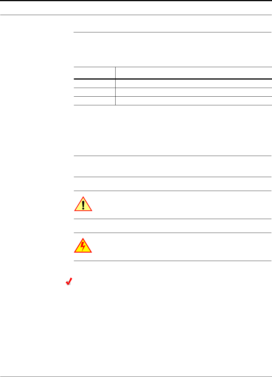
The minimum configuration of a Fusion SingleStar system is one Hub and one RAU
(1-1). The maximum configuration of a system is one Hub and 8 RAUs (1-8). Multi-
ple systems can be combined to provide larger configurations.
Figure 2-1 Fusion SingleStar System Hardware
System OA&M Capabilities Overview
2-4 InterReach Fusion SingleStar Installation, Operation, and Reference Manual
CONFIDENTIAL D-620605-0-20 Rev A
2.2 System OA&M Capabilities Overview
InterReach Fusion SingleStar is microprocessor controlled and contains firmware which
enables much of the operations, administration, and maintenance (OA&M) functionality.
Complete alarming, down to the field replaceable unit (that is, Fusion SingleStar Hub
and Remote Access Unit) and the cabling infrastructure, is available. All events
occurring in a system, defined as a Fusion SingleStar Hub and all of its associated
Remote Access Units, are automatically reported to the Hub. The Hub monitors sys-
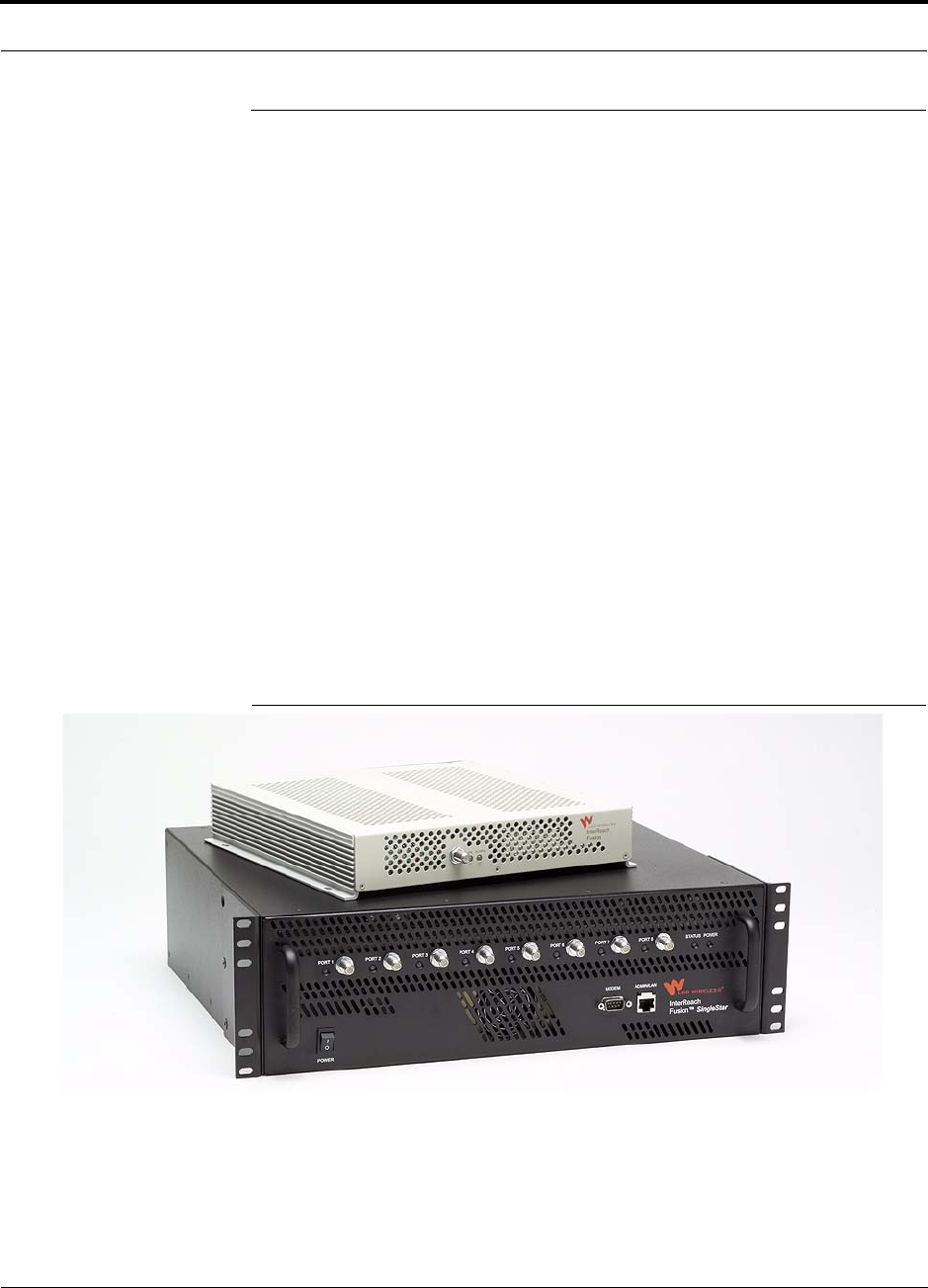
tem status and communicates that status using the following methods:
• Normally closed (NC) alarm contact closures can be tied to standard NC alarm
monitoring systems or directly to a base station for basic alarm monitoring.
• Connection Methods:
• The Hub’s front panel RJ-45 port connects directly to a PC (for local Ethernet
access).
• The Hub’s front panel RS-232 serial port connects directly to a modem (for
remote access).
• Remote access is also available with an optional 100BASE-T LAN switch con-
nections to the RJ-45 port.
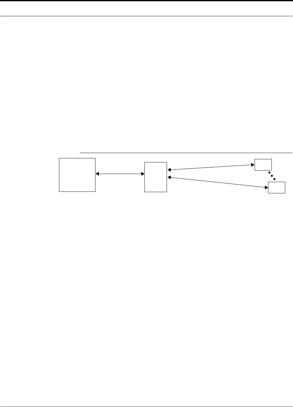
Figure 2-2 Three Methods for OA&M Communications
AdminBrowser OA&M software runs on the Fusion SingleStar Hub microprocessor
and communicates to its downstream RAUs. Using AdminBrowser, you can config-
ure a newly installed system, change system parameters, perform an end-to-end sys-
tem test, or query system status from any standard web browser (Internet Explorer)
running on your PC/laptop system.
Refer to the AdminBrowser User Manual (D-620607-0-20 Rev A) for information
about installing and using the AdminBrowser software.
PSTN
RS-232
RS-232 Ethernet
PC/Laptop
running a
Modem
Fusion SingleStar Hub
Modem
Fusion SingleStar Hub
Ethernet
LAN
Switch
F-conn.
Fusion SingleStar Hub
Fusion SingleStar Hub
Standard Browser
Use AdminBrowser to configure
or monitor a local or a remote
Fusion SingleStar system.
TCP/IP
RAU
1
2
3
R-J-45
t
Ethernet
Admin Browser
Help Hot Line (U.S. only): 1-800-530-9960 2-5
D-620605-0-20 Rev A CONFIDENTIAL
System OA&M Capabilities Overview
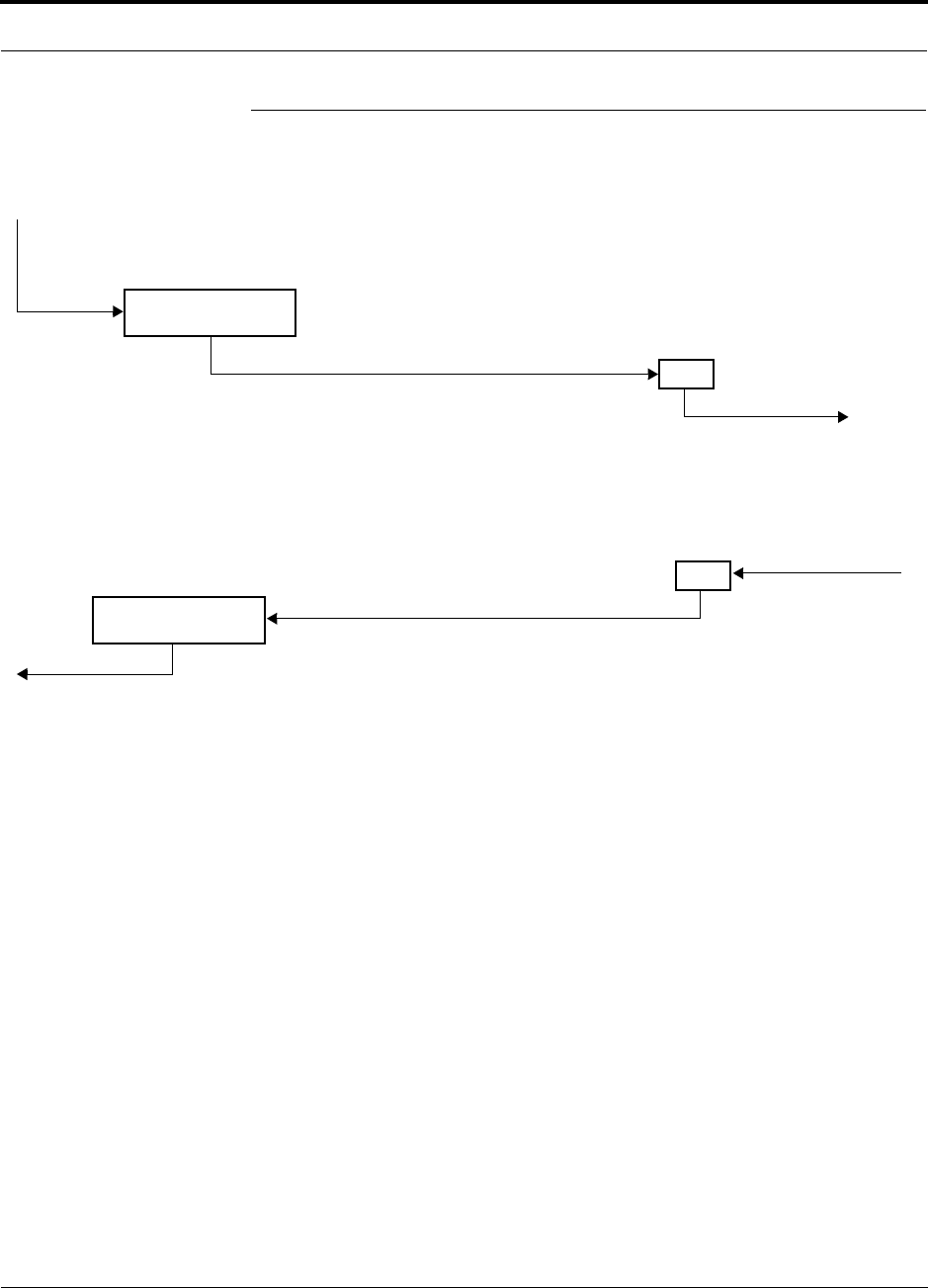
2.2.1 System Monitoring and Reporting
Each Fusion SingleStar Hub in the system constantly monitors itself and its down-
stream RAUs for internal fault and warning conditions. The results of this monitoring
are stored in memory and compared against new results.
When a Hub detects a change in status, it reports a fault or warning. Faults are indi-
cated locally by red status LEDs. Both faults and warnings are reported to Admin-
Browser software and displayed on a PC/laptop connected to the Hub’s RJ-45 port.
Passive antennas connected to the RAUs are not monitored automatically. Perform
the System Test in order to retrieve status information about antennas.
Using AdminBrowser, you can install a new system or new components, change sys-
tem parameters, and query system status. Figure 2-3 illustrates how the system
reports its status to AdminBrowser.
Figure 2-3 System Monitoring and Reporting
2.2.2 Using Alarm Contact Closures
You can connect the DB-9 female connector on the rear panel of the Fusion Single-
Star Hub to a local base station or to a daisy-chained series of Fusion, Unison,
LGCell, and/or MetroReach Focus systems.
• When you connect MetroReach Focus or a BTS to the Fusion SingleStar, the
Fusion SingleStar Hub outputs the alarms (alarm source) and MetroReach Focus
or the BTS receives the alarms (alarm sense). This is described in Section 6.6.1 on
page 6-33.
• When you connect LGCell to the Fusion SingleStar, the Fusion SingleStar Hub
receives the alarms (alarm sense) from LGCell (alarm source). This is described in
Section 6.6.2 on page 6-36.
Each RAU passes its status to
the Hub.
If a fault is detected, the
ALARM LED is red. If no fault
is detected, the LED is green.
The Hub queries the status of
each RAU and compares it to
the previously stored status.
If a fault is detected, LEDs on
the front panel turn red.
PC/Laptop
running a
standard
RAU
RAU
Use a standard browser to commu-
nicate with remotely or locally
installed SingleStarsystems running
AdminBrowser.
If a fault or warning condition is
reported, the AdminBrowser graphi-
cal user interface indicates the prob-
lem on your standard PC browser.
web browser
Fusion
SingleStar
Hub Admin-
Browser
System Connectivity
2-6 InterReach Fusion SingleStar Installation, Operation, and Reference Manual
CONFIDENTIAL D-620605-0-20 Rev A
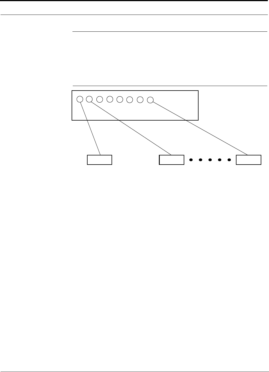
2.3 System Connectivity
The system uses standard 75 Ohm CATV cable. This makes any system expansion,
such as adding an extra antenna for additional coverage, as easy as pulling thin Ether-
net cable.
Figure 2-4 Fusion SingleStar’s Architecture
InterReach
CATVCATV CATV
up to 8 RAUs per Hub
RAU RAU RAU
Fusion SingleStar
(RG-59. 6, or 11)
Help Hot Line (U.S. only): 1-800-530-9960 2-7
D-620605-0-20 Rev A CONFIDENTIAL
System Operation
2.4 System Operation
• Downlink (Base Station to Wireless Devices)
• Uplink (Wireless Devices to Base Station)
Fusion SingleStar Hub
RAU
The Fusion SingleStar Hub receives down-
link RF signals from a base station using
The Hub converts the RF signals to IF
signals and sends them to RAUs (up to 8)
using CATV cable.
The RAU converts the IF signals
to RF and sends them to passive
antennas using coaxial cable.
Fusion SingleStar Hub
RAU
The Fusion SingleStar Hub
sends the RF signals to a
base station using coaxial
The Hub receives the IF signals from the
RAUs (up to 8) using CATV cable and con-
verts them to RF signals.
The RAU receives uplink RF
signals from the passive
antenna using coaxial cable an
converts them to IF signals.

System Specifications
2-8 InterReach Fusion SingleStar Installation, Operation, and Reference Manual
CONFIDENTIAL D-620605-0-20 Rev A
2.5 System Specifications
Table 2-1 Physical Specifications
Table 2-2 Environmental Specifications
Parameter Fusion SingleStar Hub Remote Access Unit
IF/RF Connectors 4N, female (50 ohms), 1 Downlink/Uplink pair per
band
8 F, female (CATV 75 Ohm)
1 F, female (CATV -75 Ohm)
1 N, female (coaxial) - 50 Ohm
External Alarm Connector
(contact closure)
1 9-pin D-sub, female
Maximum: 400 mA @ 60V AC/DC
Typical: 4 mA @ 12V DC
—
ADMIN/LAN Interface
Connectors
1 RJ-45, female
1 9-pin D-sub, male for optional modem
—
LED Alarm and
Status Indicators
Unit Status (1 pair):
•Power
• Status
Port Status (1 per SF connector port):
• Link/RAU
Unit Status (1 pair):
•Link
•Alarm
AC Power (Volts) Rating: 115/230V, 6/3A, 50–60 Hz
Operating Range: 90–132V/170–250V auto-ranging
—
DC Power (Volts) — 54V (from the Hub)
Power Consumption
(W)**
4 RAUs: 350 typical
8 RAUs: 5300 typical
64 max (from the Hub)
Enclosure Dimensions*
(height × width × depth)
*Excluding angle-brackets for 19'' rack mounting of hub.
**The Fusion SingleStar Hub’s typical power consumption assumes that the CATV RG-59 cable length is no more than 150 meters, the RG-6
cable length is no more than 170 meters, and RG-11 cable length is no more than 270 meters.
133.5 mm × 438 mm × 381 mm
(5.25 in. × 17.25 in. × 15 in.) (3U)
54 mm x 286 mm x 281 mm
(2.13 in. × 11.25 in. × 11.13 in.)
Weight < 9.5 kg (< 21 lbs.) < 2.1 kg (< 4.6 lbs.)
Parameter Unison Accel Hub RAU
Operating Temperature 0° to +45°C (+32° to +113°F) –25° to +45°C (–13° to +113°F)
Non-operating Temperature –20° to +85°C (–4° to +185°F) –25° to +85°C (–13° to +185°F)
Operating Humidity; non-condensing 5% to 95% 5% to 95%

Help Hot Line (U.S. only): 1-800-530-9960 2-9
D-620605-0-20 Rev A CONFIDENTIAL
System Specifications
Table 2-3 Operating Frequencies
2.5.1 RF End-to-End Performance
The following tables list the RF end-to-end performance of each protocol.
NOTE: The system gain is adjustable in 1 dB steps from 0 to 15 dB, and the
gain of each RAU can be attenuated up to 10 dB in 1dB steps.
850/1900 RAU
Fusion RAU Part Number Fusion
Band
RF Passband
Downlink
(MHz) Uplink
(MHz)
850/1900 FSN-8519-1 850 869–894 824–849
1900 1930–1990 1850–1910
900//1800 FSN-9018-1 900 925–960 880–915
1800 1805–1880 1710–1785
900/2100 FSN-9021-1 900 925–960 830–715
Table 2-4 850 MHz RF End-to-End Performance
Parameter
Typical
Downlink Uplink
Average gain with 75 m RG-59 at 25°C (77°F) (dB) 15 15
Ripple with 150 m RG-59 (dB) 2.5 3
Output IP3 (dBm) 38
Input IP3 (dBm) –5
Output 1 dB Compression Point (dBm) 26
Noise Figure 1 Hub-8 RAUs (dB) 16
Table 2-5 1900 MHz RF End-to-End Performance
Parameter
Typical
Downlink Uplink
Average gain with 75 m RG-59 at 25°C (77°F) (dB) 15 15
Ripple with 150 m RG-59 (dB) 3.5 4
Output IP3 (dBm) 38
Input IP3 (dBm) 5
Output 1 dB Compression Point (dBm) 26
Noise Figure 1 Hub-8 RAUs (dB) 17

System Specifications
2-10 InterReach Fusion SingleStar Installation, Operation, and Reference Manual
CONFIDENTIAL D-620605-0-20 Rev A
900/1800 RAU
900/2100 RAU
Table 2-8 900 MHz RF End-to-End Performance
Table 2-6 900 MHz RF End-to-End Performance
Typical
Parameter Downlink Uplink
Average Downlink gain with 75 m RG-59 at 25°C (77°F) (dB) 15 15
Ripple with 75 m RG-59 (dB) 3 4
Output IP3 (dBm) 38
Input IP3 (dBm) –5
Output 1 dB Compression Point (dBm) 26
Noise Figure 1 Hub-8 RAUs (dB) 16
Table 2-7 1800 MHz RF End-to-End Performance
Typical
Parameter Downlink Uplink
Average gain with 75 m RG-59 at 25°C (77°F) (dB) 15 15
Downlink ripple with 75 m Cat-5/5E/6 (dB) 2
Uplink ripple with 75 m RG-59 (dB) 2
Uplink gain roll off with 75 m RG-59 (dB)*
*Outside the center 60 MHz
2
Output IP3 (dBm) 38
Input IP3 (dBm) –12
Output 1 dB Compression Point (dBm) 26
Noise Figure 1 Hub-8 RAUs (dB) 17
Typical
Parameter Downlink Uplink
Average Downlink gain with 75 m RG-59 at 25°C (77°F) (dB) 15 15
Ripple with 75 m RG-59 (dB) 3 4
Output IP3 (dBm) 38
Input IP3 (dBm) –5
Output 1 dB Compression Point (dBm) 26
Noise Figure 1 Hub-8 RAUs (dB) 16

Help Hot Line (U.S. only): 1-800-530-9960 2-11
D-620605-0-20 Rev A CONFIDENTIAL
System Specifications
Table 2-9 2100 MHz RF End-to-End Performance
Parameter
Typical
Downlink Uplink
Average gain w/ 75 meters RG-59 @ 25
°
C (dB) 15 15
Ripple with 75 m RG-59 (dB) 2.5 4
Spurious Output Levels (dBm) <–30
UMTS TDD Band Spurious Output Level
1900–1920 MHz, 2010–2025 MHz (dBm/MHz) <–52
Output IP3 (dBm) 37
Input IP3 (dBm) –12
Output 1 dB Compression Point (dBm) 26
Noise Figure 1 Hub-8 RAUs (dB) 17

System Specifications
2-12 InterReach Fusion SingleStar Installation, Operation, and Reference Manual
CONFIDENTIAL D-620605-0-20 Rev A
This page is intentionally left blank.

InterReach Fusion SingleStar Installation, Operation, and Reference Manual 3-1
D-620605-0-20 Rev A CONFIDENTIAL
SECTION 3 Fusion SingleStar Hub
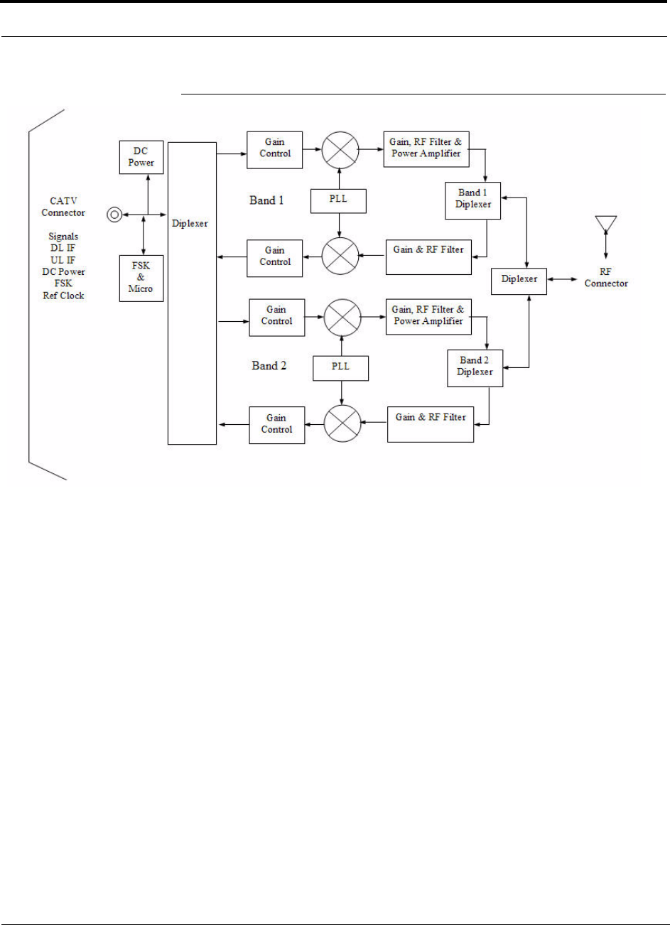
The Fusion SingleStar Hub interfaces between two individual RF sources (being base
station, repeater, or MetroReach Focus system) and up to eight Remote Access Units.
The Fusion SingleStar is a multi-band system. One RF source (Band 1 or RF1) goes
to the 35 MHz band and the other RF source (Band 2 or RF2) goes to the 75 MHz
band. The system installs in a 19" equipment rack and is usually collocated with the
RF source in a telecommunications closet.
• Downlink Path
The Fusion SingleStar Hub receives downlink RF signals from each RF source
(RF1, RF2) using coaxial cable. It converts the signals to IF and sends them to up
to eight RAUs using CATV cable. The Hub also sends OA&M communication to
the RAUs using the CATV cable.
• Uplink Path
The Fusion SingleStar Hub receives uplink IF signals from up to eight RAUs using
CATV cable. It converts the signals to RF and sends them to an RF source (RF1,
RF2) using coaxial cable. The Hub also receives status information from the RAUs
using the CATV cable.
Figure 3-1 shows a detailed view of the major RF and functional blocks of the Hub.
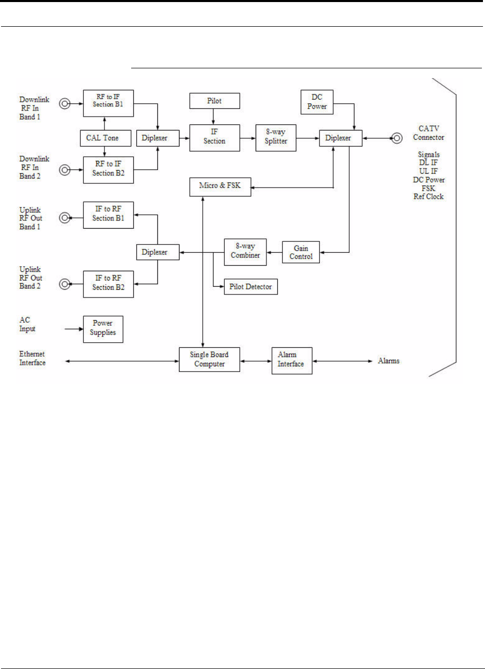
3-2 InterReach Fusion SingleStar Installation, Operation, and Reference Manual
CONFIDENTIAL D-620605-0-20 Rev A
Figure 3-1 Fusion SingleStar Hub Block Diagram
Help Hot Line (U.S. only): 1-800-530-9960 3-3
D-620605-0-20 Rev A CONFIDENTIAL
Fusion SingleStar Hub Front Panel
3.1 Fusion SingleStar Hub Front Panel
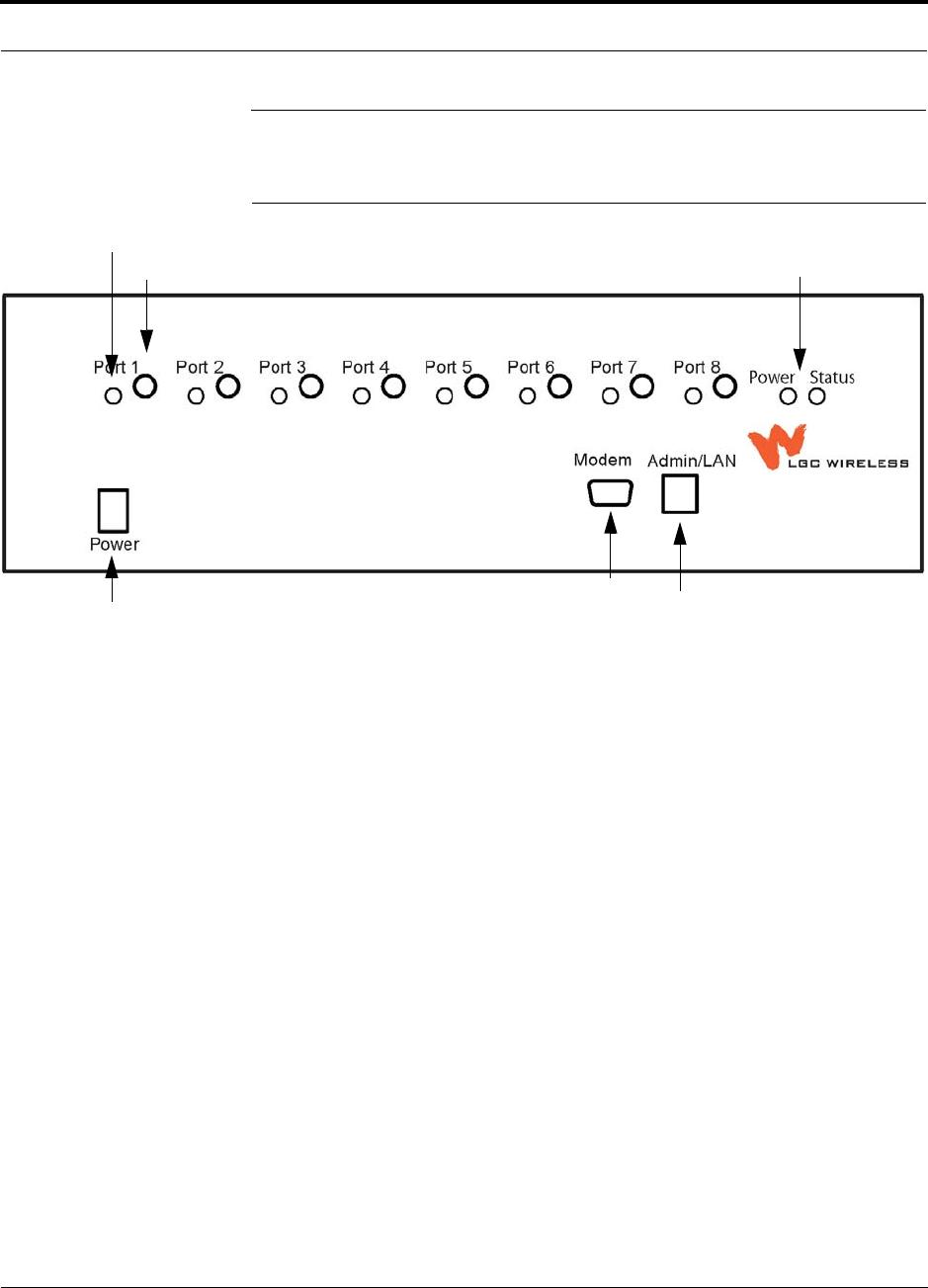
Figure 3-2 Fusion SingleStar Hub Front Panel
1. One port LED per F connector port for link status and downstream RAU status (8
pair total).
2. Eight CATV cable F connectors (labeled PORT 1, 2, 3, 4, 5, 6, 7, 8)
3. One pair of unit status LEDs
• One LED for unit power status (labeled POWER)
• One LED for unit status (labeled STATUS)
4. One 9-pin D-sub male connector for system remote dial-up communication and
diagnostics using a modem (labeled MODEM)
5. One RJ-45 female connector for system communication and diagnostics using a
PC/laptop with direct connect or using a LAN switch (labeled ADMIN/LAN)
6. Power switch
1
4
2 3
5
1
23
645
InterReach
Fusion SingleStar

Fusion SingleStar Hub Front Panel
3-4 InterReach Fusion SingleStar Installation, Operation, and Reference Manual
CONFIDENTIAL D-620605-0-20 Rev A
3.1.1 F Connectors
The eight F connectors on the Hub are for the CATV cables used to transmit and
receive signals to and from RAUs. Use only 75 ohm F connectors on the CATV
cable.
The CATV cable also delivers DC electrical power to the RAUs. The Hub’s DC volt-
age output is 54V DC nominal. A current limiting circuit protects the Hub if any port
draws excessive power.
NOTE: For system performance, it is important to use only low loss solid cop-
per center conductor CATV cable with quality F connectors that use captive cen-
terpin connectors. Refer to Appendix A for approved cables and connectors.
3.1.2 Communications RS-232 Serial Connector
Remote Monitoring
Use a standard serial cable to connect a modem to the 9-pin D-sub male serial con-
nector for remote monitoring or configuring. The cable typically has a DB-9 female
and a DB-25 male connector. Refer to Appendix A.3 on page A-3 for the cable pinout
Remote monitoring is also available by connecting the RJ-45 (ADMIN/LAN) port to
a LAN switch for remote Ethernet LAN access or direct dial-up router access.
Local Monitoring
Use a crossover Ethernet cable to connect a laptop or PC to the RJ-45 female connec-
tor for local monitoring or configuring using the AdminBrowser resident software.
The cable typically has a RJ-45 male connector on both ends. Refer to Appendix A.4
on page A-3 for the cable pinout.
3.1.3 Hub LED Indicators
The unit’s front panel LEDs indicate faults and commanded or fault lockouts. The
LEDs do not indicate warnings or whether the system test has been performed. Use the
LEDs to provide basic information only, or as a backup when you are not using Admin-
Browser.
Upon power up, the Hub goes through a 20-second test to check the LED lamps. Dur-
ing this time, the LEDs blink through the states shown in Table 3-1, letting you visu-
ally verify that the LED lamps and the firmware are functioning properly. Upon
completion of initialization, the LEDs stay in one of the first two states shown in
Table 3-1.
Help Hot Line (U.S. only): 1-800-530-9960 3-5
D-620605-0-20 Rev A CONFIDENTIAL
Fusion SingleStar Hub Front Panel
The Hub automatically sends the program bands command to all connected RAUs. A
mismatched band causes a fault message to be displayed in AdminBrowser and the
RAU has a fault condition.
NOTE: Refer to Section 8.3.2 for troubleshooting using the LEDs.
NOTE: AdminBrowser must be used for troubleshooting the system. Only
use LEDs for backup or confirmation. However, if there are communication
problems within the system, the LEDs may provide additional information
that is not available using AdminBrowser.
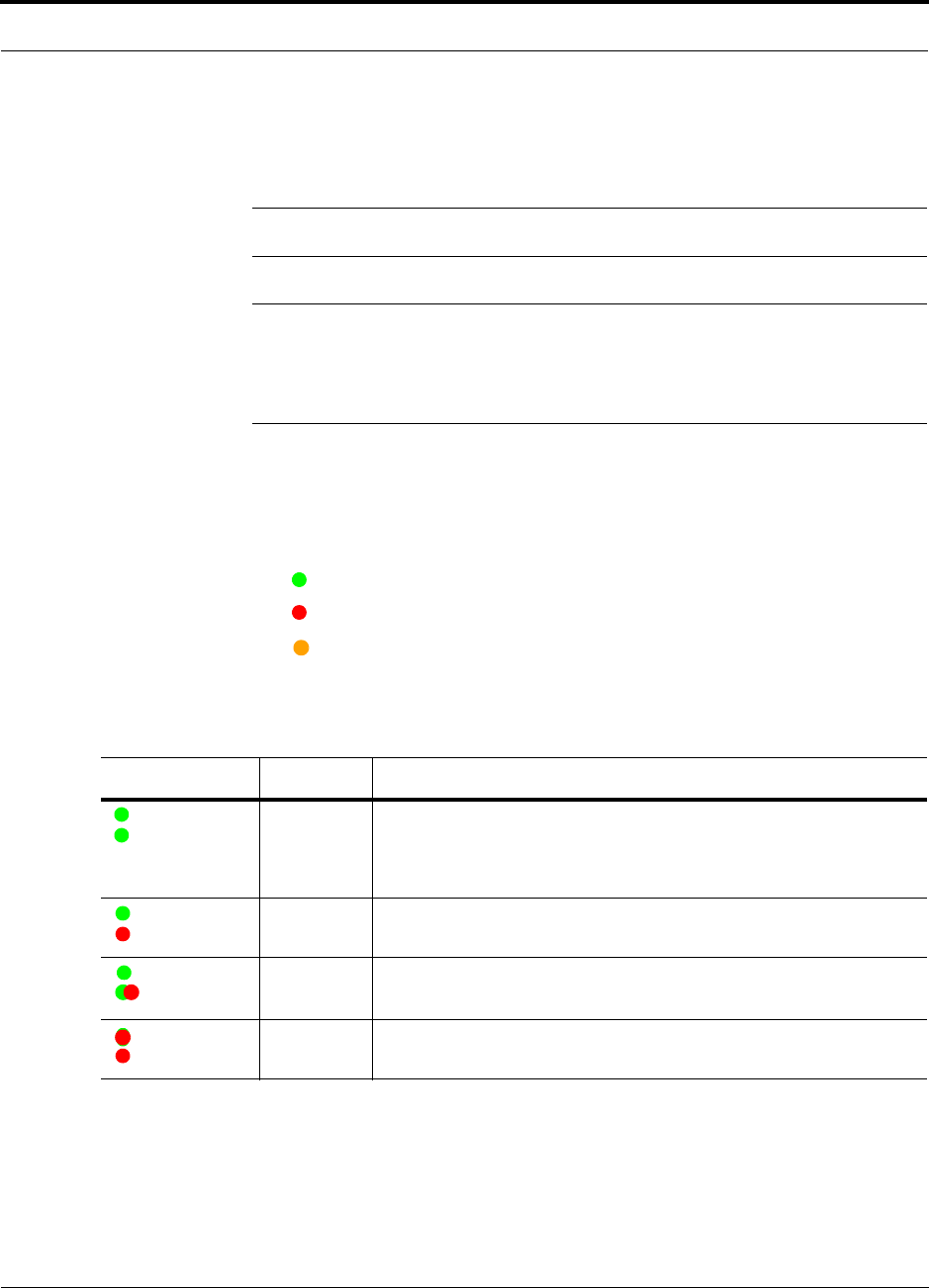
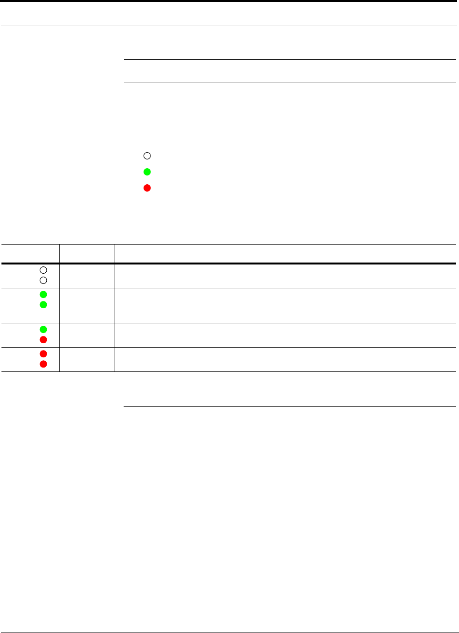
Status LEDs
The Hub has one pair of status LEDs, labeled POWER and STATUS, which can be in
one of the states shown in Table 3-1. These LEDs can be:
steady green
steady red
orange
There is no off state when the unit’s power is on.
Table 3-1 Fusion SingleStar Hub Status LED States
LED State Indicates
Green
Green
• The Hub is connected to power and all power supplies are operating.
• The Hub is not reporting a fault; however, the system test may need to
be performed or a warning condition may exist. Use AdminBrowser to
determine this.
Green
Red
• The Hub is connected to power and all power supplies are operating.
• The Hub is reporting a fault or lockout condition.
Green
Orange
• The Hub is connected to power and all power supplies are operating.
• The Hub DL input signal level is too high.
Red
Red
• One or more power supplies are out-of-specification.
POWER
STATUS
POWER
STATUS
POWER
STATUS
POWER
STATUS
Fusion SingleStar Hub Front Panel
3-6 InterReach Fusion SingleStar Installation, Operation, and Reference Manual
CONFIDENTIAL D-620605-0-20 Rev A
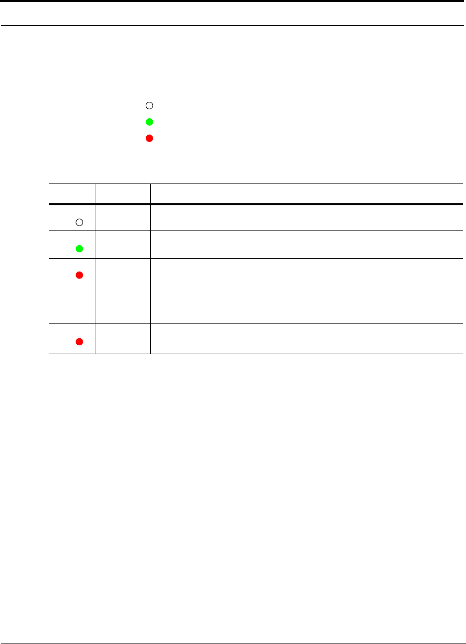
RJ-45 Port LEDs
The Hub has a port LED, labeled PORT, for each of the eight RJ-45 ports. The port
LEDs can be in one of the states shown in Table 3-2. These LEDs can be:
off
steady green
flashing red (60 pulses per minute [PPM])
Table 3-2 Fusion SingleStar Hub Port LED States
LED State Indicates
Off • The RAU is not connected.
Green
• The RAU is connected.
• No faults from the RAU.
Red
(60 PPM)
• The RAU was disconnected.
• The RAU is not communicating.
• The RAU port power is tripped.
• 54 VDC is shutdown due to an EH over-temperature condition.
Red
(Steady)
• The RAU is connected.
• The RAU is reporting a fault or lockout condition.
PORT
PORT
PORT
PORT
Help Hot Line (U.S. only): 1-800-530-9960 3-7
D-620605-0-20 Rev A CONFIDENTIAL
Fusion SingleStar Hub Rear Panel
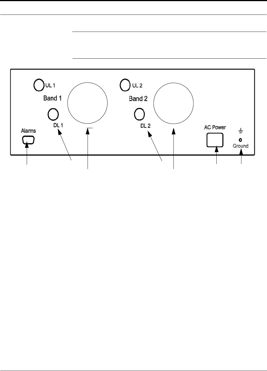
3.2 Fusion SingleStar Hub Rear Panel
Figure 3-3 Fusion SingleStar Hub Rear Panel
1. AC power cord connector
2. Two air exhaust vents
3. Two N-type, female connectors fore each band (Band 1 and Band 2):
• Uplink (labeled UL 1 and UL 2)
• Downlink (labeled DL ‘1 and DL 2)
4. One 9-pin D-sub female connector for contact alarm monitoring (labeled
ALARMS)
5. Ground lug for connecting unit to frame ground (labeled GROUND)
1
422
335

Fusion SingleStar Hub Rear Panel
3-8 InterReach Fusion SingleStar Installation, Operation, and Reference Manual
CONFIDENTIAL D-620605-0-20 Rev A
3.2.1 Fusion SingleStar Hub Rear Panel Connectors
3.2.1.1 9-pin D-sub Connector
The 9-pin D-sub connector (labeled DIAGNOSTIC 1) provides a contact alarm for fault
and warning system alarm monitoring.
Table 3-3 lists the function of each pin on the 9-pin D-sub connector.
Table 3-3 9-pin D-sub Pin Connector Functions
This interface can both generate two source contact alarms (Fault and Warning) and
sense 3 single external alarm contacts (Alarm Sense Input 1 through 3).
3.2.1.2 N-type Female Connectors
There are two N-type female connectors on the rear panel of the Hub:
• The DOWNLINK connector receives downlink RF signals from a repeater, local
base station, or MetroReach Focus system.
• The UPLINK connector transmits uplink RF signals to a repeater, local base sta-
tion, or MetroReach Focus system.
CAUTION:The UPLINK and DOWNLINK ports cannot handle a DC power
feed from the local base station. If the DC power is present, a DC block must
be used or the Fusion SingleStar hub may be damaged.
Pin Function
1 Alarm Sense Input Ground
2 Alarm Sense Input 3
3 Alarm Sense Input 2
4 Warning Source Contact (positive connection)
5 Warning Contact (negative connection)
6 DC Ground (common)
7 Fault Source Contact (positive connection)
8 Alarm Sense Input 1
9 Fault Source Contact (negative connection)

Help Hot Line (U.S. only): 1-800-530-9960 3-9
D-620605-0-20 Rev A CONFIDENTIAL
Faults, Warnings, and Status Messages
3.3 Faults, Warnings, and Status Messages
3.3.1 Description
The Fusion SingleStar Hub monitors and reports changes or events in system perfor-
mance to:
• Ensure that its amplifiers and IF/RF paths are functioning properly.
• Ensure that Remote Access Units are connected and functioning properly.
An event is classified as fault, warning, or status message.
• Faults are service impacting.
• Warnings indicate a possible service impact.
• Status messages are generally not service impacting.
The Fusion SingleStar Hub periodically queries attached Remote Access Units for
their status. Both faults and warnings are reported to a connected PC/laptop running a
standard browser communicating with the AdminBrowser software. Only faults are
indicated by LEDs.
For more information regarding the events, refer to:
• page 8-5 for Hub faults.
• page 8-13 for Hub warnings.
• page 8-15 for Hub status messages.
• page 8-19 for troubleshooting Hub LEDs.
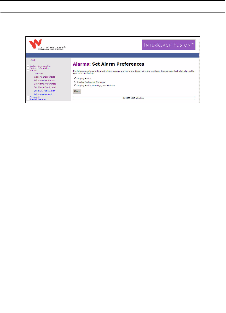
3.3.2 View Preference
AdminBrowser 1.0 or higher enables you to select (using the screen shown in
Figure 3-4) the type of events to be displayed.
Faults, Warnings, and Status Messages
3-10 InterReach Fusion SingleStar Installation, Operation, and Reference Manual
CONFIDENTIAL D-620605-0-20 Rev A
Figure 3-4 Preferences Check Boxes
To modify the setting, using AdminBrowser, select Alarms J Set Alarm Preference
and select the desired choice. After you click OK, AdminBrowser refreshes and
updates the tree view according to the new setting.
NOTE: The setting is strictly visual and only in AdminBrowser. There is no
affect on the hardware itself. By default, the event filtering is set to “Enable
viewing of Faults only”.
The only exception when the event filtering is ignored is during the Install/Configure
command. All events are displayed regardless of the event filtering setting. This
ensures a smooth installation.

Help Hot Line (U.S. only): 1-800-530-9960 3-11
D-620605-0-20 Rev A CONFIDENTIAL
Fusion SingleStar Hub Specifications
3.4 Fusion SingleStar Hub Specifications
Table 3-4 Fusion SingleStar Hub Specifications
Specification Description
Enclosure Dimensions (H × W × D) 133.5 mm × 438 mm × 381 mm
(5.25 in. × 17.25 in. × 15 in.) (3U)
Weight < 9.5 kg (< 21 lb)
Operating Temperature 0° to +45°C (+32° to +113°F)
Non-operating Temperature –20° to +85°C (–4° to +185°F)
Operating Humidity, non-condensing 5% to 95%
External Alarm Connector
(contact closure)
1 9-pin D-sub, female
Maximum: 400 mA @ 60V AC/DC
Typical: 4 mA @ 12V DC
ADMIN/LAN Interface Connector 1 RJ-45, female
1 9-pin D-sub, male for optional modem
RF Connectors 4N, female (50 ohms), 1 Downlink/Uplink pair per band
8 F, female (CATV 75 ohm)a
a. For system performance, it is important that you use only 75 Ohm CATV cable with solid copper center conductor.
LED Fault and Status Indicators Unit Status (1 pair):
•Power
• Status
Port Status (1 pair per SF-connector port):
• Link/RAU
AC Power Rating: 115/230V, 6/3A, 50–60 Hz
Operating Range: 90–132V/170–250V auto-ranging
Power Consumption (W) 4 RAUs: 305 typical
8 RAUs: 530 typical
MTBF 45,040 hours

Fusion SingleStar Hub Specifications
3-12 InterReach Fusion SingleStar Installation, Operation, and Reference Manual
CONFIDENTIAL D-620605-0-20 Rev A
This page is intentionally left blank.

InterReach Fusion SS Installation, Operation, and Reference Manual 4-1
D-620605-0-20 Rev A CONFIDENTIAL
SECTION 4 Remote Access Unit
The Remote Access Unit (RAU) is an active transceiver that interfaces between a
Fusion SingleStar Hub and passive antennas, which transmit the RF signals to wire-
less devices. The RAU is installed above ceiling tiles or attached to a wall or pole. It
is located at the site where RF is to be delivered.
•Downlink Path
The RAU receives downlink IF signals from a Fusion SingleStar Hub using CATV
cable. It converts the signals to RF and sends them to a passive RF antenna using
coaxial cable. Also, the RAU receives configuration information from the Fusion
SingleStar Hub using the CATV cable.
•Uplink Path
The RAU receives uplink RF signals from a passive RF antenna using coaxial
cable. It converts the signals to IF and sends them to a Fusion SingleStar Hub using
CATV cable. Also, the RAU sends its status information to the Fusion SingleStar
Hub using CATV cable.
4-2 InterReach Fusion SS Installation, Operation, and Reference Manual
CONFIDENTIAL D-620605-0-20 Rev A
Figure 4-1 Remote Access Unit Block Diagram

Help Hot Line (U.S. only): 1-800-530-9960 4-3
D-620605-0-20 Rev A CONFIDENTIAL
Remote Access Unit Connectors
The Fusion SingleStar RAUs are manufactured to a specific set of bands (one 35
MHz-Band 1, one 75 MHz-Band 2). Table 4-1 lists the Fusion RAUs, the Fusion
Band, and the frequency bands they cover.
4.1 Remote Access Unit Connectors
4.1.1 N Connector
The RAU has one female N connector. The connector is a duplexed RF input/output
port that connects to a standard 50Ω passive antenna using coaxial cable.
4.1.2 F Connector
The RAU has one F female connector that connects it to a Fusion SingleStar Hub
using CATV 75 Ohm cable. Use RG-59, 6, or 11 solid copper center conductor
cables.
NOTE: For system performance, it is important that you use only low loss,
solid copper center conductor CATV cable with quality F connectors that use
capture centerpin conductors. Refer to Appendix A for more information.
4.2 RAU LED Indicators
Upon power up, the RAU goes through a two-second test to check the LED lamps.
During this time, the LEDs blink green/green red/red, letting you visually verify that
the LED lamps and the firmware are functioning properly.
Table 4-1 Frequency Bands Covered by Fusion RAUs
Fusion
RAU Part Number Fusion
Band
RF Passband
Downlink
(MHz) Uplink
(MHz) RAU
Band RAU
Bandwidth
850/1900 FSN-8519-1 850 869–894 824–849 1 25 MHz
1900 1930–1990 1850–1910 2 60 MHz
900//1800 FSN-9018-1 900 925–960 880–915 1 35 MHz
1800 1805–1880 1710–1785 2 75 MHz
900/2100 FSN-9021-1 900 925–960 830–715 1 35 MHz
2100 2110–2170 1920–1980 2 60 MHz
Faults and Warnings
4-4 InterReach Fusion SS Installation, Operation, and Reference Manual
CONFIDENTIAL D-620605-0-20 Rev A
NOTE: Refer to Section 8 for troubleshooting using the LEDs.
Status LEDs
The RAU status LEDs can be in one of the states shown in Table 4-2. These LEDs
can be:
off
steady green
steady red
There is no off state when the unit’s power is on.
4.3 Faults and Warnings
Both fault and warning conditions are reported to the Fusion SingleStar Hub where
they are stored. Only faults are indicated by LEDs.
For more information, refer to:
• page 8-11 for RAU faults.
• page 8-14 for RAU warnings.
• page 8-17 for RAU status messages.
Table 4-2 Remote Access Unit LED States
LED State Indicates
Off
Off
• The RAU is not receiving DC power.
Green
Green
• The RAU is powered and is not indicating a fault condition. Communication with the
Fusion SingleStar Hub is normal; however, the system test may need to be performed or a
warning condition may exist (use AdminBrowser to determine this).
Green
Red
• The RAU is indicating a fault or lockout condition, but communication with the Fusion Sin-
gleStar Hub is normal.
Red
Red
• The RAU is reporting a fault or lockout condition and is not able to communicate with the
Fusion SingleStar Hub
LINK
ALARM
LINK
ALARM
LINK
ALARM
LINK
ALARM

Help Hot Line (U.S. only): 1-800-530-9960 4-5
D-620605-0-20 Rev A CONFIDENTIAL
Remote Access Unit Specifications
4.4 Remote Access Unit Specifications
NOTE: For system performance, it is important that you use only low loss,
solid copper center conductor CATV cable with quality F connectors that use
capture centerpin conductors. Refer to Appendix A for more information.
Table 4-3 Remote Access Unit Specifications
Specification Description
Dimensions (H × W × D) 133.5 mm × 438 mm × 381 mm
(5.25 in. × 17.25 in. × 15 in.)
Weight < 2.1 kg (< 4.6 lb.)
Operating Temperature –25° to +45°C (–13° to +113°F)
Non-operating Temperature –25° to +85°C (–13° to +185°F)
Operating Humidity, non-condensing 5% to 95%
RF Connectors 1 F, female (CATV - 75 ohms)
1 N, female (coaxial 50 ohms)
LED Alarm and Status Indicators Unit Status (1 pair):
•Link
•Alarm
Maximum Heat Dissipation (W) 50 typical, 64 max (from the Hub)
MTBF 211,600 hours

Remote Access Unit Specifications
4-6 InterReach Fusion SS Installation, Operation, and Reference Manual
CONFIDENTIAL D-620605-0-20 Rev A

InterReach Fusion SingleStar Installation, Operation, and Reference Manual 5-1
D-620605-0-20 Rev A CONFIDENTIAL
SECTION 5 Designing a Fusion SingleStar
Solution
Designing a Fusion SingleStar solution is a matter of determining coverage and
capacity needs. This requires the following steps:
1. Determine the wireless service provider’s requirements: Refer to Section 5.1,
“Downlink RSSI Design Goal,” on page 5-3.
The following information is typically provided by the service provider:
• Frequency (for example, 1900 MHz)
• Band (for example, “A-F” band in the PCS spectrum)
• Protocol (for example, COMA, GSM, 1xRTT, GPRS, and so on)
• Number of sectors and peak capacity per sector (translates to the umber of RF
carriers that the system will have to transmit)
• Downlink RSSI design goal (RSSI, received signal strength at the wireless
handset, for example, –85 dBm)
The design goal is always a stronger signal than the mobile phone needs. It
includes inherent factors which affect performance.
• RF source (base station or BDA), type of equipment if possible.
2. Determine the downlink power per carrier from the RF source through the
DAS: Refer to Section 5.2, “Maximum Output Power per Carrier,” on page
5-4.
The maximum power per carrier is a function of modulation type, the number of
RF carriers, signal quality issues, regulatory emissions requirements, and Fusion
SS’s RF performance. Power per carrier decreases as the number of carriers
increases.
3. Develop an RF link budget: Refer to Section 5.4, “Estimating RF Coverage,”
on page 5-13.
Knowing both the power per carrier and RSSI design goal, you can develop an RF
downlink link budget which estimates the allowable path loss from an RAU’s
antenna to the wireless handset.
allowable path loss = power per carrier + antenna gain – design goal
Satisfactory performance can be expected as long as path loss is below this level.

5-2 InterReach Fusion SingleStar Installation, Operation, and Reference Manual
CONFIDENTIAL D-620605-0-20 Rev A
4. Determine the in-building environment: Refer to Section 5.4, “Estimating RF
Coverage,” on page 5-13.
• Determine which areas of the building require coverage (entire building, public
areas, parking levels, and so on.)
• Obtain floor plans to determine floor space of building and the wall layout of
the proposed areas to be covered. Floor plans are also useful when you are
selecting antenna locations.
• If possible, determine the building’s construction materials (sheetrock, metal,
concrete, and so on.)
• Determine the type of environment:
– Open layout (for example, a convention center)
– Dense, close walls (for example, a hospital)
– Mixed use (for example, an office building with hard wall offices and cubi-
cles)
5. Determine the appropriate estimated path loss slope that corresponds to the
type of building and its layout, and estimate the coverage distance for each
RAU: Refer to Section 5.4, “Estimating RF Coverage,” on page 5-13.
Use the path loss slope (PLS), which gives a value to the RF propagation charac-
teristics within the building, to convert the RF link budget into an estimate of the
coverage distance per antenna. This helps establish the quantities of Fusion Sin-
gleStar equipment you need. The actual path loss slope that corresponds to the
specific RF environment inside the building can also be determined empirically
by performing an RF site-survey of the building. This involves transmitting a cal-
ibrated tone for a fixed antenna and making measurements with a mobile antenna
throughout the area surrounding the transmitter.
6. Determine the items required to connect to the base station: Refer to
Section 5.6, “Connecting a Hub to a Base Station,” on page 5-23.
Once you know the quantities of Fusion SingleStar equipment to be used, you can
determine the accessories (combiners/dividers, surge suppressors, repeaters,
attenuators, circulators, and so on.) required to connect the system to the base sta-
tion.
The individual elements that must be considered in designing a Fusion SingleStar
solution are explained in the following sections.
NOTE: Access the LGC Wireless portal at LGCWireless.com for on-line
dimensioning and design tools.

Help Hot Line (U.S. only): 1-800-530-9960 5-3
D-620605-0-20 Rev A CONFIDENTIAL
Downlink RSSI Design Goal
5.1 Downlink RSSI Design Goal
Wireless service providers typically provide a minimum downlink signal level and an
associated confidence factor when specifying coverage requirements. These two fig-
ures of merit are a function of wireless handset sensitivity and margins for fading and
body loss. Wireless handset sensitivity is the weakest signal that the handset can pro-
cess reliably and is a combination of the thermal noise in the channel, noise figure of
the handset receiver front end and minimum required SNR. Fade margins for multi-
path fading (fast or small-scale) and log-normal shadow fading (slow or large-scale)
are determined by the desired confidence factor, and other factors. Downlink RSSI
design goal calculations for the TDMA protocol are shown below for a 95% area cov-
erage confidence factor.
Downlink design goals on the order of –85 dBm are typical for protocols, such as
GSM and iDEN. Wireless service providers may choose a higher level to ensure that
in-building signal dominates any macro signal that may be leaking into the building.
Noise Power
10 Log (KT)+10 Log (30 KHz); K=1.38X10⁻²³, T=300 degrees Kelvin
–129 dBm
Wireless Handset Noise Figure 7 dB
Required SNR 17 dB
Multipath Fade Margin
95% Reliability for Rician K=7 dB
6dB
Log-normal Fade Margin
95% Area/88% Edge Reliability for 35 dB PLS and 9.5 dB Sigma
11 dB
Body Attenuation + 3 dB
Downlink RSSI Design Goal (PDesignGoal)
Signal level received by wireless handset at edge of coverage area
–85 dBm
Maximum Output Power per Carrier
5-4 InterReach Fusion SingleStar Installation, Operation, and Reference Manual
CONFIDENTIAL D-620605-0-20 Rev A
5.2 Maximum Output Power per Carrier
The following tables show the recommended maximum power per carrier out of the
RAU N connector for different frequencies, protocols, and numbers of carriers. These
maximum levels are dictated by RF signal quality and regulatory emissions issues. In
general, as the number of RF carrier increases, the maximum power per carrier
decreases. If these levels are exceeded, signal quality will be degraded and/or regula-
tor requirements will be violated. The maximum input power to the Hub is deter-
mined by subtracting the system gain from the maximum output power of the RAU.
System gain is software selectable from 0 dB to 15 dB in 1 dB steps. Additionally,
both the uplink and downlink gain of each RAU can be reduced by 10 dB in 1 dB
steps.
When connecting a Hub to a base station or repeater, attenuation on the downlink is
typically required to avoid exceeding Fusion SS’s maximum output power recom-
mendations.
WARNING: Exceeding the maximum input power may cause perma-
nent damage to the Hub. Do not exceed the maximum composite input
power of 1W (+30 dBm) to the Hub at any time.
NOTE: These specifications are for downlink power at the RAU output (excluding
antenna).

Help Hot Line (U.S. only): 1-800-530-9960 5-5
D-620605-0-20 Rev A CONFIDENTIAL
Maximum Output Power per Carrier
5.2.1 850 MHz Cellular
Table 5-1 Cellular Power per Carrier
No. of
Carriers
Power per Carrier (dBm)
AMPS TDMA GSM EDGE CDMA WCDMA
116.5 16.5 16.5 16.5 16 15
2
16.5 16.5 13.5 13.5 13 11
3
16.5 15.0 11.5 11.5 11 8
4
13.5 13 10.0 10.0 10.0 6.5
5
12.0 11.5 9.0 9.0 9.0 5.0
6
10.5 10.5 8.5 8.5 8.0
7
9.5 9.5 8.0 8.0 7.5
8
8.5 8.5 7.5 7.5 7.0
9
8.0 8.0 7.0 7.0
10
7.0 7.5 6.5 6.5
11
7.0 7.0 6.5 6.5
12
6.5 6.5 6.0 6.0
13
6.0 6.5 6.5 5.5
14
5.5 6.0 5.5 5.5
15
5.5 5.5 5.0 5.0
16
5.0 5.5 5.0 5.0
20
4.0 4.5 4.5 4.0
30
2.0 2.5 3.0 2.0
Note: Operation at or above these output power levels may prevent Fusion SingleStar from meeting RF performance specifications or FCC Part 15 and
EN55022 emissions requirements.

Maximum Output Power per Carrier
5-6 InterReach Fusion SingleStar Installation, Operation, and Reference Manual
CONFIDENTIAL D-620605-0-20 Rev A
5.2.2 900 MHz EGSM and EDGE
Table 5-2 GSM/EGSM and EDGE Power per Carrier
No. of
Carriers
Power per Carrier (dBm)
GSM EDGE
116.0 16.0
2 13.0 13.0
3 11.0 11.0
4 10.0 10.0
59.09.0
68.08.0
77.57.5
87.07.0
96.56.5
10 6.0 6.0
11 5.5 5.5
12 5.0 5.0
13 5.0 5.0
14 4.5 4.5
15 4.0 4.0
16 4.0 4.0
20 3 3
30 1 1
Note: Operation at or above these output power levels may prevent Fusion
SingleStar from meeting RF performance specifications or FCC Part 15 and
EN55022 emissions requirements.

Help Hot Line (U.S. only): 1-800-530-9960 5-7
D-620605-0-20 Rev A CONFIDENTIAL
Maximum Output Power per Carrier
5.2.3 1800 MHz DCS
Table 5-3 DCS Power per Carrier
No. of
Carriers
Power per Carrier (dBm)
GSM EDGE
116.5 16.5
2 14.5 14.5
3 12.5 12.5
4 11.5 11.5
5 10.5 10.5
69.5 9.5
79.0 9.0
88.5 8.0
98.0 7.5
10 7.5 7.0
11 7.0 6.5
12 6.5 6.0
13 6.5 6.0
14 6.0 5.5
15 5.5 5.0
16 5.5 5.0
20 4.5 4.0
30 2.5 2.0
Note: Operation at or above these output power levels may pre-
vent Fusion SingleStar from meeting RF performance specifica-
tions or FCC Part 15 and EN55022 emissions requirements.

Maximum Output Power per Carrier
5-8 InterReach Fusion SingleStar Installation, Operation, and Reference Manual
CONFIDENTIAL D-620605-0-20 Rev A
5.2.4 1900 MHz PCS
Table 5-4 PCS Power per Carrier
No. of
Carriers
Power per Carrier (dBm)
TDMA GSM EDGE CDMA WCDMA
116.5 16.5 16.5 16.0 15.0
2
16.5 15.5 15.5 13.0 11.0
3
15.0 13.5 13.5 11.0 8.0
4
13.0 12.0 12.0 10.0 6.5
5
11.5 11.0 10.5 9.0 5.0
6
10.5 10.5 9.5 8.0
7
9.5 10.0 9.0 7.5
8
8.5 9.0 8.0 7.0
9
8.0 8.5 7.5
10
7.5 8.0 7.0
11
7.0 7.5 6.5
12
6.5 7.0 6.0
13
6.5 6.5 6.0
14
6.0 6.5 5.5
15
5.5 6.0 5.0
16
5.5 5.5 5.0
20
4.5 4.5 4.0
30
2.5 3.0 2.0
Note: Operation at or above these output power levels may prevent Fusion SingleStar from meeting RF
performance specifications or FCC Part 15 and EN55022 emissions requirements.

Help Hot Line (U.S. only): 1-800-530-9960 5-9
D-620605-0-20 Rev A CONFIDENTIAL
Maximum Output Power per Carrier
5.2.5 2.1 GHz UMTS
Table 5-5 UMTS Power per Carrier
No. of
Carriers
Power per
Carrier (dBm)
WCDMA
1
15.0
211.0
38.0
46.5
55.0
64.0
73.0
Note: measurements taken with no baseband clipping.
Note: Operation at or above these output power levels may prevent Fusion SingleStar
from meeting RF performance specifications or FCC Part 15 and EN55022 emissions
requirements.
Maximum Output Power per Carrier
5-10 InterReach Fusion SingleStar Installation, Operation, and Reference Manual
CONFIDENTIAL D-620605-0-20 Rev A
900 MHz Paging/SMR
Designing for Capacity Growth
Fusion SingleStar systems are deployed to enhance in-building coverage and/or to
off-load capacity from a macro cell site. In many instances, subscriber usage
increases with time and the wireless provider responds by increasing the load on the
installed Fusion SingleStar system. For example, the initial deployment might only
require two RF carriers, but four RF carriers may be needed in the future based on
capacity growth forecasts. There are two options for dealing with this scenario:
1. Design the initial coverage with a maximum power per carrier for four RF carri-
ers. This will likely result in additional RAUs.
2. Design the initial coverage for two RF carriers, but reserve RAU ports on the Hub
for future use. These ports can be used to fill potential coverage holes once the
power per carrier is lowered to accommodate the two additional carriers.
Table 5-6 Paging/SMR Power per Carrier
No. of
Carriers
Power per Carrier (dBm)
iDEN Analog
FM CQPSK C4FM Mobitex POCSAG/
REFLEX
117.5 26.0 22.0 26.0 26.0 26.0
2
14.0 19.5 17.0 19.5 19.5 19.5
3
11.5 16.5 14.5 16.0 16.0 16.0
4
10.0 13.5 12.5 13.5 13.5 13.5
5
9.0 12.0 11.0 11.5
6
8.0 10.5 9.5 10.0
7
7.0 9.5 9.0 9.0
8
6.5 8.5 8.0 8.5
9
6.0 8.0 7.5 7.5
10
5.5 7.0 7.0 7.0
Note: Operation at or above these output power levels may prevent Fusion SingleStar from meeting RF performance specifications or FCC Part 15 and
EN55022 emissions requirements. Refer to the Fusion SingleStar Installation, Operation, and Reference manual for system design information.

Help Hot Line (U.S. only): 1-800-530-9960 5-11
D-620605-0-20 Rev A CONFIDENTIAL
System Gain
5.3 System Gain
The system gain of the Fusion SingleStar defaults to 0 dB or can be set up to 15 dB in
1 dB increments. In addition, uplink and downlink gains of each RAU can be inde-
pendently decreased by 10 dB in one dB steps using AdminBrowser.
5.3.1 System Gain (Loss) Relative to CATV Cable Type Length
The recommended minimum length of CATV cable is 10 meters (33 ft) and the rec-
ommended maximum lengths are as follows:
• For RG-59 cable 150 meters (492 ft).
• For RG-6 cable 200 meters (656 ft).
• For RG-6 cable 300 meters (984 ft).
If the system is operated with CATV cable less than 10 meters (33 ft) in length, sys-
tem performance will be greatly compromised.
If the CATV cable is longer than the recommended distance per cable type, the gain
of the system will decrease, as shown in Table 5-7.
Table 5-7 System Gain (Loss) Relative to CATV Cable Length
Typical change in system gain (dB)
RG-59 Downlink Uplink
800 MHz iDEN, 850 MHz GSM and CDMA; 900 MHz
GSM and EGSM, and iDEN
180 m –1.0 –0.7
190 m –3.2 –2.4
200 m –5.3 –4.1
220 m –7.5 –5.8
240 m –9.7 –7.6
1800 MHz GSM (DCS); 1900 MHz TDMA, CDMA, and
GSM
180 m –1.0 –0.7
190 m –4.0 –2.4
200 m –6.4 –4.1
220 m –8.8 –5.8
240 m –11.3 –7.6
2.1 GHz UMTS
180 m –1.0 –0.7
190 m –3.2 –2.4

System Gain
5-12 InterReach Fusion SingleStar Installation, Operation, and Reference Manual
CONFIDENTIAL D-620605-0-20 Rev A
200 m –5.3 –4.1
220 m –7.5 –5.8
240 m –9.7 –7.6
Table 5-7 System Gain (Loss) Relative to CATV Cable Length
Typical change in system gain (dB)
RG-59 Downlink Uplink
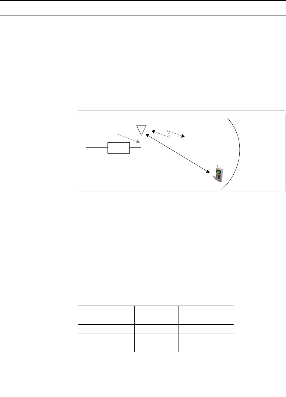
Help Hot Line (U.S. only): 1-800-530-9960 5-13
D-620605-0-20 Rev A CONFIDENTIAL
Estimating RF Coverage
5.4 Estimating RF Coverage
The maximum output power per carrier (based on the number and type of RF carriers
being transmitted) and the minimum acceptable received power at the wireless device
(that is, the RSSI design goal) essentially establish the RF downlink budget and, con-
sequently, the maximum allowable path loss (APL) between the RAU’s antenna and
the wireless device. Since in-building systems, such as the Fusion SS, are generally
downlink-limited, this approach is applicable in the majority of deployments.
Figure 5-1 Determining APL between the Antenna and the Wireless Device
APL = (P – Lcoax + G) – RSSI (1)
where:
• APL = the maximum allowable path loss in dB
• P = the power per carrier transmitted by the RAU in dBm
•L
coax = the coaxial cable loss between the RAU and passive antenna in dB
• G = the gain of the passive antenna in dBi
Coaxial cable is used to connect the RAU to an antenna. Table 5-8 lists coaxial cable
loss for various cable lengths.
You can calculate the distance, d, corresponding to the maximum allowable path loss
using equations introduced in the following sections.
Table 5-8 Coaxial Cable Losses (Lcoax)
Length of Cable
(.195 in. diameter) Loss at
850 MHz(dB) Loss at
1900 MHz (dB)
0.9 m (3 ft) 0.6 0.8
1.8 m (6 ft) 1.0 1.5
3.0 m (10 ft) 1.5 2.3
RAU
P = power per Distance = d
G = Antenna Gain
RSSI = power at the
wireless device
carrier from the RAU
Lcoax = Coaxial cable loss

Estimating RF Coverage
5-14 InterReach Fusion SingleStar Installation, Operation, and Reference Manual
CONFIDENTIAL D-620605-0-20 Rev A
5.4.1 Path Loss Equation
In-building path loss obeys the distance power law1 in equation (2):
PL = 20log10(4πd0f/c) + 10nlog10(d/d0) + Χs(2)
where:
• PL is the path loss at a distance, d, from the antenna
• d = the distance expressed in meters
•d
0 = free-space path loss distance in meters
• f = the operating frequency in Hertz.
• c = the speed of light in a vacuum (3.0 × 10⁸ m/sec).
•n = the path loss exponent and depends on the building “clutter” and frequency
of operation
•Χs = a normal random variable that depends on partition material and geome-
tries inside the building and is accounted for by the log-normal fade margin
used in the downlink RSSI design goal calculation
As a reference, Table 5-9 provides estimates of signal loss for some RF barriers1.
1. Rappaport, Theodore S. Wireless Communications, Principles, and Practice. Prentice Hall PTR, 1996.
Table 5-9 Average Signal Loss of Common Building Materials
Partition Type Loss (dB) Frequency (MHz)
Metal wall 26 815
Aluminum siding 20 815
Foil insulation 4 815
Cubicle walls 1.4 900
Concrete block wall 13 1300
Concrete floor 10 1300
Sheetrock 1 to 2 1300
Light machinery 3 1300
General machinery 7 1300
Heavy machinery 11 1300
Equipment racks 7 1300
Assembly line 6 1300
Ceiling duct 5 1300
Metal stairs 5 1300

Help Hot Line (U.S. only): 1-800-530-9960 5-15
D-620605-0-20 Rev A CONFIDENTIAL
Estimating RF Coverage
5.4.2 RAU Coverage Distance
Use equations (1) and (2), on pages 5-13 and 5-14, respectively, to estimate the dis-
tance from the antenna to where the RF signal decreases to the minimum acceptable
level at the wireless device.
With d0 set to one meter and path loss slope (PLS) defined as 10n, Equation (2) can
be simplified to:
PL(d) = 20log10(4πf/c) + PLS·log10(d) (3)
Table 5-10 gives the value of the first term of Equation (3) (that is., (20log10(4πf/c))
for various frequency bands.
Table 5-10 Frequency Bands and the Value of the First Term in Equation (3)
Frequency
Band (MHz) Mid-Band
Frequency
(MHz) 20log10(4πf/c)
Uplink Downlink
850 MHz Cellular 824–849 869–894 859 31.1
900 MHz GSM 890–915 935–960 92.5 31.8
900 MHz EGSM 880–915 925–960 920 31.7
1800 MHz DCS 1710–1785 1805–1880 1795 37.5
1900 MHz PCS 1850–1910 1930–1990 1920 38.1
2.1 GHz UMTS 1920–1980 2110–2170 2045 38.7

Estimating RF Coverage
5-16 InterReach Fusion SingleStar Installation, Operation, and Reference Manual
CONFIDENTIAL D-620605-0-20 Rev A
Table 5-11 shows estimated PLS for various environments that have different “clut-
ter” (that is, objects that attenuate the RF signals, such as walls, partitions, stairwells,
equipment racks, and so.).
By setting the path loss to the maximum allowable level (PL = APL), equation (3) can
be used to estimate the maximum coverage distance of an antenna connected to an
RAU, for a given frequency and type of in-building environment.
d = 10^((APL - 20log10(4πf/c))/PLS) (4)
Table 5-11 Estimated Path Loss Slope for Different In-Building Environments
Environment Type Example PLS for
800/850/900 MHz PLS for
1800/1900 MHz
Open Environment
very few RF obstructions
Parking Garage, Convention Center 33.7 30.1
Moderately Open Environment
low-to-medium amount of RF
obstructions
Warehouse, Airport, Manufacturing 35 32
Mildly Dense Environment
medium-to-high amount of RF
obstructions
Retail, Office Space with approxi-
mately 80% cubicles and 20% hard
walled offices
36.1 33.1
Moderately Dense Environment
medium-to-high amount of RF
obstructions
Office Space with approximately
50% cubicles and 50% hard walled
offices
37.6 34.8
Dense Environment
large amount of RF obstructions
Hospital, Office Space with approxi-
mately 20% cubicles and 80% hard
walled offices
39.4 38.1

Help Hot Line (U.S. only): 1-800-530-9960 5-17
D-620605-0-20 Rev A CONFIDENTIAL
Estimating RF Coverage
For reference, Tables 5-12 through 5-16 show the distance covered by an antenna for
various in-building environments. The following assumptions were made:
• Path loss Equation (4)
• 6 dBm output per carrier at the RAU output
• 3 dBi antenna gain
• RSSI design goal = –85 dBm (typical for narrowband protocols, but not for
spread-spectrum protocols)
Table 5-12 Approximate Radiated Distance from Antenna
for 850 MHz Cellular Applications
Environment Type
Distance from Antenna
Meters Feet
Open Environment 73 241
Moderately Open Environment 63 205
Mildly Dense Environment 55 181
Moderately Dense Environment 47 154
Dense Environment 39 129
Table 5-13 Approximate Radiated Distance from Antenna
for 900 MHz GSM Applications
Facility
Distance from Antenna
Meters Feet
Open Environment 70 230
Moderately Open Environment 60 197
Mildly Dense Environment 53 174
Moderately Dense Environment 45 148
Dense Environment 38 125

Estimating RF Coverage
5-18 InterReach Fusion SingleStar Installation, Operation, and Reference Manual
CONFIDENTIAL D-620605-0-20 Rev A
Table 5-14 Approximate Radiated Distance from Antenna
for 900 MHz EGSM Applications
Facility
Distance from Antenna
Meters Feet
Open Environment 70 231
Moderately Open Environment 60 197
Mildly Dense Environment 53 174
Moderately Dense Environment 45 149
Dense Environment 38 125
Table 5-15 Approximate Radiated Distance from Antenna
for 1800 MHz DCS Applications
Facility
Distance from Antenna
Meters Feet
Open Environment 75 246
Moderately Open Environment 58 191
Mildly Dense Environment 50 166
Moderately Dense Environment 42 137
Dense Environment 30 100

Help Hot Line (U.S. only): 1-800-530-9960 5-19
D-620605-0-20 Rev A CONFIDENTIAL
Estimating RF Coverage
5.4.3 Examples of Design Estimates
Example Design Estimate for an 850 MHz TDMA Application
1. Wireless service provider’s requirements:
• Cellular (859 MHz = average of the lowest uplink and the highest downlink
frequency in 850 MHz Cellular band)
•TDMA provider
• 12 TDMA carriers in the system
• –85 dBm design goal and 95% area coverage
• Base station with simplex RF connections
2. Power Per Carrier: The tables in Section 5.2, “Maximum Output Power per Car-
rier,” on page 5-4 provide maximum power per carrier information. The 800 MHz
TDMA table (on page 5-5) indicates that Fusion SingleStar can support 12 carri-
ers with a recommended maximum power per carrier of +7.5 dBm. The input
power should be set to the desired output power minus the system gain.
3. Link Budget: In this example, a design goal of –85 dBm is used. Suppose 3 dBi
omni-directional antennas are used in the design. Then, the maximum RF propa-
gation loss should be no more than 95.5 dB (+7.5 dBm + 3 dBi + 85 dBm) over
Table 5-16 Approximate Radiated Distance from Antenna
for 1900 MHz PCS Applications
Facility
Distance from Antenna
Meters Feet
Open Environment 72 236
Moderately Open Environment 56 183
Mildly Dense Environment 49 160
Moderately Dense Environment 40 132
Dense Environment 29 96
Table 5-17 Approximate Radiated Distance from Antenna
for 2.1 GHz UMTS Applications
Facility
Distance from Antenna
Meters Feet
Open Environment 69 226
Moderately Open Environment 54 176
Mildly Dense Environment 47 154
Moderately Dense Environment 39 128
Dense Environment 28 93

Estimating RF Coverage
5-20 InterReach Fusion SingleStar Installation, Operation, and Reference Manual
CONFIDENTIAL D-620605-0-20 Rev A
95% of the area being covered. It is important to note that a design goal such as
–85 dBm is derived by taking into account multipath fading and log-normal shad-
owing characteristics. Thus, this design goal will only be met “on average” over
95% of the area being covered. At any given point, a fade may drop the signal
level beneath the design goal.
4. Building information:
• Two floor building with 9,290 sq. meters (100,000 sq. ft.) per floor; total
18,580 sq. meters (200,000 sq. ft.)
• Walls are sheetrock construction; suspended ceiling tiles
• Antennas used will be omni-directional, ceiling mounted
• Standard office environment, 50% hard wall offices and 50% cubicles
5. Path Loss Slope: For a rough estimate, Table 5-11, “Estimated Path Loss Slope for
Different In-Building Environments” on page 5-16, shows that a building with 50%
hard wall offices and 50% cubicles, at 859 MHz, has an approximate path loss slope
(PLS) of 37.6. Given the RF link budget of 95.5 dB, the distance of coverage from
each RAU will be 52 meters (170.6 ft). This corresponds to a coverage area of
8,494 sq. meters (91,425 sq. ft.) per RAU (refer to Section 5.4.1 for details on path
loss estimation). For this case, assume a circular radiation pattern, though the actual
area covered will depend upon the pattern of the antenna and the obstructions in the
facility.
6. Equipment Required: Since you know the building size, you can now estimate
the Fusion SingleStar equipment quantities needed. Before any RF levels are
tested in the building, you can estimate that two antennas per level will be needed.
This assumes no propagation between floors. If there is propagation, you may not
need antennas on every floor.
a. 2 antennas per floor × 2 floors = 4 RAUs
b. 4 RAUs ÷ 8 (maximum 8 RAUs per Fusion SingleStar Hub) = 1 Hub
Check that the CATV cable distances are as recommended. If the distances differ,
use the tables in Section 5.3, “System Gain,” on page 5-11 to determine system
gains or losses. The path loss may need to be recalculated to assure adequate sig-
nal levels in the required coverage distance.
The above estimates assume that all cable length requirements are met. If RAUs can-
not be placed within reach of the Hub, then the InterReach Fusion SingleStar system,
with its longer reach, should be considered.
An RF Site Survey and Building Evaluation is required to accurately establish the
Fusion SingleStar equipment quantities required for the building. The site survey
measures the RF losses within the building to determine the actual PLS, which will be
used in the final path loss formula to determine the actual requirements of the Fusion
SingleStar system.

Help Hot Line (U.S. only): 1-800-530-9960 5-21
D-620605-0-20 Rev A CONFIDENTIAL
Estimating RF Coverage
Example Design Estimate for a 1900 MHz CDMA Application
1. Wireless service provider’s requirements:
• PCS (1920 MHz = average of the lowest uplink and the highest downlink fre-
quency in 1900 MHz PCS band)
•CDMA provider
• 3 CDMA carriers in the system
• –75 dBm design goal and 95% area coverage
• Base station with simplex RF connections
2. Power Per Carrier: The tables in Section 5.2, “Maximum Output Power per Car-
rier,” on page 5-4 provide maximum power per carrier information. The 1900
MHz CDMA table (on page 5-8) indicates that Fusion SingleStar can support 3
carriers with a recommended maximum power per carrier of +11.0 dBm. The
input power should be set to the desired output power minus the system gain.
3. Building information:
• Two floor building with 4,645 sq. meters (50,000 sq. ft.) per floor; total
9,290 sq. meters (100,000 sq. ft.)
• Walls are sheetrock construction; suspended ceiling tiles
• Antennas used will be omni-directional, ceiling mounted
• Standard office environment, 80% hard wall offices and 20% cubicles
4. Link Budget: In this example, a design goal of –75 dBm is used. Suppose 3 dBi
omni-directional antennas are used in the design. Then, the maximum RF propa-
gation loss should be no more than 89.0 dB (11.0 dBm + 3 dBi + 75 dBm) over
95% of the area being covered. It is important to note that a design goal such as
–75 dBm is usually derived taking into account multipath fading and log-normal
shadowing characteristics. Thus, this design goal will only be met “on average”
over 95% of the area being covered. At any given point, a fade may bring the sig-
nal level underneath the design goal.
5. Path Loss Slope: For a rough estimate, Table 5-11, “Estimated Path Loss Slope for
Different In-Building Environments” on page 5-16, shows that a building with 80%
hard wall offices and 20% cubicles, at 1900 MHz, has an approximate path loss
slope (PLS) of 38.1. Given the RF link budget of 89 dB, the distance of coverage
from each RAU will be 21.8 meters (71.5 ft). This corresponds to a coverage area
of 1492 sq. meters (16,050 sq. ft.) per RAU (refer to Section 5.4.1 for details on
path loss estimation). For this case assume a circular radiation pattern, though the
actual area covered will depend upon the pattern of the antenna and the obstructions
in the facility.
6. Equipment Required: Since you know the building size, you can now estimate
the Fusion SingleStar equipment quantities needed. Before any RF levels are
tested in the building, you can estimate that 3 antennas per level will be needed.
This assumes no propagation between floors. If there is propagation, you may not
need antennas on every floor.
a. 3 antennas per floor × 2 floors = 6 RAUs

Designing for a Neutral Host System
5-22 InterReach Fusion SingleStar Installation, Operation, and Reference Manual
CONFIDENTIAL D-620605-0-20 Rev A
b. 6 RAUs ÷ 8 (maximum 8 RAUs per Fusion SingleStar Hub) = 1 Hub
Check that the CATV cable distances are as recommended. If the distances differ,
use the tables in Section 5.3, “System Gain,” on page 5-11 to determine system
gains or losses. The path loss may need to be recalculated to assure adequate sig-
nal levels in the required coverage distance.
The above estimates assume that all cable length requirements are met. If RAUs can-
not be placed within reach of the Hub, then the InterReach Fusion SingleStar system,
with its longer reach, should be considered.
An RF Site Survey and Building Evaluation is required to accurately establish the
Fusion SingleStar equipment quantities required for the building. The site survey
measures the RF losses within the building to determine the actual PLS, which will be
used in the final path loss formula to determine the actual requirements of the Fusion
SingleStar system.
5.5 Designing for a Neutral Host System
A “neutral host” system supports more than one wireless service provider and typi-
cally supports more than one frequency band and/or protocol. The wireless network-
ing equipment is often owned, installed, and managed by a third or “neutral” party
that serves as the “host” by leasing the equipment to the providers.
Designing for a neutral host system uses the same design rules previously explained.
Since a neutral host system typically uses multiple base stations (BTS). Refer to
Section 6.5, “Interfacing the Fusion SingleStar to an RF Source,” on page 6-22 for
connection options.

Help Hot Line (U.S. only): 1-800-530-9960 5-23
D-620605-0-20 Rev A CONFIDENTIAL
Connecting a Hub to a Base Station
5.6 Connecting a Hub to a Base Station
The Fusion SingleStar system supports two RF sources: one for Band 1 and one for
Band 2. This section explains how each band can be connected to its associated base
station.
Each Fusion SingleStar band has separate system gain parameters. For example,
Band 1 can be set for +5 dB of downlink system gain while Band 2 can have +15 dB
of downlink system gain. Thus, each band can be configured as a separate system to
allow for full integration to its associated base station.
When connecting each of the Fusion SingleStar Hub bands to its base station, the fol-
lowing equipment may be required: circulators, filter diplexers, directional couplers,
combiner/splitters, attenuators, coax cables, and connectors. In addition, use the fol-
lowing considerations to achieve optimal performance:
1. The downlink power from the base stations must be attenuated enough so that the
power radiated by the RAU does not exceed the maximum power per carrier listed
in Section 5.2, “Maximum Output Power per Carrier,” on page 5-4.
2. The uplink attenuation should be small enough that the sensitivity of the overall
system is limited by Fusion SingleStar, not by the attenuator. However, some base
stations trigger alarms if the noise or signal levels are too high. In this case the
attenuation must be large enough to prevent this from happening.
CAUTION:The UPLINK and DOWNLINK ports cannot handle a DC power
feed from a BTS. If DC power is present, a DC block must be used or the
Fusion SingleStar hub may be damaged.
If, in an area covered by Fusion SingleStar, a mobile phone indicates good signal
strength but consistently has difficulty completing calls, it is possible that the attenua-
tion between Fusion SingleStar and the base station needs to be adjusted. In other
words, it is possible that if the uplink is over-attenuated, the downlink power will pro-
vide good coverage, but the uplink coverage distance will be small.
When there is an excessive amount of loss between the Fusion SingleStar Hub uplink
and its associated band’s base station, the uplink system gain can be increased to as
much as 15 dB to prevent a reduction in the overall system sensitivity.
5.6.1 Uplink Attenuation
The attenuation between the Hub’s uplink port and the associated band’s base station
reduces both the noise level and the desired signals out of Fusion SingleStar. Setting
the attenuation on the uplink is a trade-off between keeping the noise and maximum
signal levels transmitted from Fusion SingleStar to the base station receiver low while
not reducing the SNR (signal-to-noise ratio) of the path from the RAU inputs to the

Connecting a Hub to a Base Station
5-24 InterReach Fusion SingleStar Installation, Operation, and Reference Manual
CONFIDENTIAL D-620605-0-20 Rev A
base station inputs. This SNR can not be better than the SNR of Fusion SingleStar by
itself, although it can be significantly worse.
A good rule of thumb is to set the uplink attenuation such that the noise level out of
Fusion SingleStar is within 10 dB of the base station’s sensitivity.
5.6.2 RAU Attenuation and ALC
The RAU attenuation and ALC are set using the AdminBrowser Advanced RAU Set-
tings command.
Embedded within the uplink RF front-end of each Fusion Remote Access Unit Band
is an ALC circuit. This ALC circuit protects the Fusion SingleStar system from over-
load and excessive intermodulation products due to high-powered mobiles or other
signal sources that are within the supported frequency band and are in close proximity
to the RAU.
Each individual Band of the Fusion SingleStar has an uplink ALC circuit that oper-
ates as a feedback loop. A power detector measures the level of each band’s uplink
RF input and if that level exceeds –30 dBm, an RF attenuator is activated. The level
of attenuation is equal to the amount that the input exceeds –30 dBm. The following
sequence describes the operation of the ALC circuit, as illustrated in Figure 5-2.
1. The RF signal level into either Band of the RAU rises above the activation thresh-
old (–30 dBm), causing that ALC loop to enter into the attack phase.
2. During the attack phase, the ALC loop increases the attenuation (0 to 30 dB) until
the detector reading is reduced to the activation threshold. The duration of this
attack phase is called the attack time.
3. After the attack time, the ALC loop enters the hold phase and maintains a fixed
attenuation so long as the high-level RF signal is present.
4. The RF signal level drops below the release threshold (–45 dBm) and the ALC
loop enters the release phase.
5. During the release phase, the ALC loop holds the attenuation for a fixed period
then quickly releases the attenuation.
An important feature of the ALC loop is that in Step 3, the attenuation is maintained
at a fixed level until the signal drops by a significant amount. This prevents the ALC
loop from tracking variations in the RF signal itself and distorting the waveform
modulation.
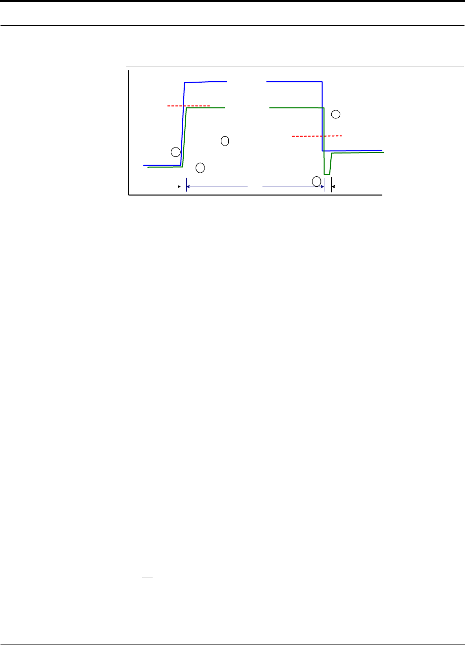
Help Hot Line (U.S. only): 1-800-530-9960 5-25
D-620605-0-20 Rev A CONFIDENTIAL
Connecting a Hub to a Base Station
Figure 5-2 ALC Operation
5.6.2.1 Using the RAU 10 dB Attenuation Setting
Each RAU band can, independently of the other RAUs in a system, have its uplink or
downlink gain attenuated by 10dB in 1dB steps for each RAU band. This is accom-
plished by selecting the check boxes in the Advanced RAU Settings dialog box.
There are two check boxes: one for setting the downlink attenuation and another for
setting the uplink attenuation for each band.
•Downlink Attenuation: The downlink attenuator provides a mechanism to reduce
the signal strength from an RAU band. For instance, this could be for an RAU
band located near a window in a tall building that is causing excessive leakage to
the macro-network. In such a case it is important to attenuate the downlink only.
The uplink should not be attenuated. If the uplink is attenuated, the uplink sensitiv-
ity is reduced and mobile phones in the area of that RAU band will have to trans-
mit at a higher power. This would increase interference to the outdoor network
from such mobiles.
•Uplink Attenuation: The uplink attenuator attenuates environmental noise picked
up by an RAU band located in an area where heavy electrical machinery is operat-
ing. In such environments the electrical noise can be quite high and it is useful to
reduce the amount of such noise that gets propagated through the distributed
antenna system. Attenuating the uplink of an RAU band located in areas of high
electrical noise helps preserve the sensitivity of the rest of the system.
The effect of activating the uplink or downlink attenuators is to reduce the coverage
area of the adjusted RAU band. The coverage radius will be reduced by roughly a fac-
tor of 2. More specifically, if d is the coverage distance without attenuation and d’ is
the coverage radius with the attenuation, then
where PLS is path loss slope (dBm).
Input Signal
Level
Activation
Level
-30dBm
Release
Level
-45dBm
Output Signal
Level
Time
Hold
Phase
Release
Phase
Attack
Phase
1
2
3
4
5
PLSdB
d
d/10
10
'=

Connecting a Hub to a Base Station
5-26 InterReach Fusion SingleStar Installation, Operation, and Reference Manual
CONFIDENTIAL D-620605-0-20 Rev A
5.6.2.2 Using the Uplink ALC Setting
Uplink automatic level control (UL ALC) circuitry for each band within the RAU
provides automatic level control on high-power signals in the uplink path. This func-
tionality is required to prevent RF signal compression caused by a single or multiple
wireless devices in very close proximity to the RAU band. Compression causes signal
degradation and, ultimately, dropped calls and data errors, and should be prevented.
Two settings are available to optimize UL ALC performance:
•Multiple Operators: Use when more than one operator and/or protocol is present
in the Fusion SingleStar system’s band frequency or adjacent frequency bands.
This setting is most commonly used.
•Single Operator and Protocol: Use when only one operator and protocol is
on-the-air within the Fusion SingleStar system’s configured and adjacent fre-
quency bands. This setting is seldom used.

Help Hot Line (U.S. only): 1-800-530-9960 5-27
D-620605-0-20 Rev A CONFIDENTIAL
Connecting a Hub to a Base Station
This page is intentionaly left blank.

Connecting a Hub to a Base Station
5-28 InterReach Fusion SingleStar Installation, Operation, and Reference Manual
CONFIDENTIAL D-620605-0-20 Rev A

InterReach Fusion SingleStar Installation, Operation, and Reference Manual 6-1
D-620605-0-20 Rev A CONFIDENTIAL
SECTION 6 Installing Fusion SingleStar
6.1 Installation Requirements
Before and during installation, keep in mind these sources of potential problems:
• Fault cabling/connector
• Malfunction of one or more Fusion SingleStar components
• Antenna, base station, or repeater problem
• External RF interface
• Tripped circuit breaker
• Equipment is not grounded
• Using a crossover Ethernet cable that does not support full hardware handshaking
when using AdminBrowser
NOTE: Faulty cabling is the cause of a vast majority of problems. All CATV cable
should be tested to TIA/EIA 570-A specifications.

Installation Requirements
6-2 InterReach Fusion SingleStar Installation, Operation, and Reference Manual
CONFIDENTIAL D-620605-0-20 Rev A
6.1.1 Component Location Requirements
Fusion SingleStar components are intended to be installed in indoor locations only.
6.1.2 Cable and Connector Requirements
Fusion SingleStar equipment operates over CATV 75 Ohm cable with F connectors.
These cables are widely-used, industry standards for the cable TV industry. The regu-
lations and guidelines for Fusion SingleStar cable installation are identical to those
specified by the TIA/EIA 568-B standard and the TIA/EIA/570-A standards.
LGC Wireless recommends solid copper center conductor, plenum-rated CATV cable
and connectors for conformity to building codes, standards, and to ensure stated per-
formance of distance and RF specifications.
Commscope 2065V cable or equivalent is required for RG-59.
Commscope 2279V cable or equivalent is required for RG-6.
Commscope 2293K cable may also be used for RG-11.
NOTE: In order to meet FCC and CE Mark emissions requirements, the CATV
cable must be screened and it must be grounded using shielded F connectors at both
ends.
LGC Wireless recommends connectors with fixed centerpins to ensure proper seating
and to eliminage oxidation, which occurs with bare center conductors. Recommended
conductors are as follows:
• FP-C4F for commScope 2065V cable
• FP-C55A for CommScope 2279V cable
• FP-C71A for CommScope 2293K cable
6.1.3 Distance Requirements
Table 6-1 shows the distances between Unison components and related equipment.
Table 6-1 Distance Requirements
Equipment
Combination Cable Type Cable Length Additional Information
Repeater/BTS to
Fusion SingleStar
Hub
Coaxial; N male
connectors
3–6 m (10–20 ft) typical Limited by loss and noise.
Refer to your link budget
calculation.
10 m (33 ft) maximum Limited by CE Mark require-
ments.

Help Hot Line (U.S. only): 1-800-530-9960 6-3
D-620605-0-20 Rev A CONFIDENTIAL
Installation Requirements
Fusion SingleStar
Hub to RAU
CATV 75 Ohm;
shielded F male con-
nectors
• Minimum: 10 meters (33 ft)
•Maximum:
150 meters (492 ft) for RG-59;
170 meters (558 ft) for RG-6;
275 meters (902 ft) for RG-11
Refer to “System Gain (Loss) Relative to
CATV Cable Type Length” on page 5-11.
Refer to “System Gain (Loss)
Relative to CATV Cable
Type Length” on page 5-11.
RAU to passive
antenna
Coaxial; N male
connectors
1–3.5 m (3–12 ft) typical Limited by loss and noise.
Refer to your link budget
calculation.
Table 6-1 Distance Requirements
Equipment
Combination Cable Type Cable Length Additional Information

Safety Precautions
6-4 InterReach Fusion SingleStar Installation, Operation, and Reference Manual
CONFIDENTIAL D-620605-0-20 Rev A
6.2 Safety Precautions
6.2.1 Installation Guidelines
Use the following guidelines when installing LGC Wireless equipment:
1. Provide sufficient airflow and cooling to the equipment to prevent heat build-up
from exceeding the maximum ambient air temperature specification. Do not com-
promise the amount of airflow required for safe operation of the equipment.
2. If you are removing the system, turn it off and remove the power cord first. There
are no user-serviceable parts inside the components.
3. The internal power supplies have internal fuses that are not user replaceable. Con-
sider the worst-case power consumption shown on the product labels when provi-
sioning the equipment’s AC power source and distribution.
4. Verify that the Hub is grounded.
NOTE: Be careful with the mechanical loading of the rack mounted hub.
Mount the equipment in the rack in such a way that a hazardous condition,
due to uneven mechanical loading, does not result, .
6.2.2 General Safety Precautions
The following precautions apply to LGC Wireless products:
• The units have no user-serviceable parts. Faulty or failed units are fully replaceable
through LGC Wireless. Please contact us at:
1-800-530-9960 (U.S. only)
+1-408-952-2400 (International)
• Although modeled after an Ethernet/LAN architecture and connectivity, the units
are not intended to connect to Ethernet data hubs, routers, cards, or other similar
data equipment.
• When you connect a radiating antenna to an RAU, firmly hand-tighten the N con-
nector – DO NOT over-tighten the connector.
WARNING: To reduce the risk of fire or electric shock, do not
expose this equipment to rain or moisture. The components are
intended for indoor use only. Do not install the RAU outdoors. Do not
connect an RAU to an antenna that is located outdoors where it could
be subject to lightning strikes, power crosses, or wind.
• The Hub and RAU units are designed for intra-building cabling only. Outdoor
routing of any cabling to these units shall not exceed 140 feet.

Help Hot Line (U.S. only): 1-800-530-9960 6-5
D-620605-0-20 Rev A CONFIDENTIAL
Preparing for System Installation
6.3 Preparing for System Installation
6.3.1 Pre-Installation Inspection
Follow this procedure before installing Fusion SingleStar equipment:
1. Verify the number of packages received against the packing list.
2. Check all packages for external damage; report any external damage to the ship-
ping carrier. If there is damage, a shipping agent should be present before you
unpack and inspect the contents because damage caused during transit is the
responsibility of the shipping agent.
3. Open and check each package against the packing list. If any items are missing,
contact LGC Wireless customer service (refer to Section 6.2.2 on page 6-4).
4. If damage is discovered at the time of installation, contact the shipping agent.
6.3.2 Installation Checklist
Table 6-2 Installation Checklist
3Installation Requirement Consideration
Floor Plans Installation location of equipment clearly marked
System Design Used to verify frequency bands after installation
Power available:
Fusion SingleStar Hub (AC)
To RAU (DC)
Hub’s power cord is 2 m (6.5 ft) long.
115/230V, 6/3A, 50–60 Hz
54V (from the Hub)
Rack space available 133.5 mm (5.25 in.) high (3U)
Clearance for air circulation:
Fusion SingleStar Hub
RAU
76 mm (3 in.) front and rear, 51 mm (2 in.) sides
76 mm (3 in.) all around
Suitable operating environment:
Fusion SingleStar Hub
RAUs
Indoor location only
0° to +45°C (+32° to +113°F)
5% to 95% non-condensing humidity
–25° to +45°C (–13° to +113°F)
5% to 95% non-condensing humidity
Donor Antenna-to-Fusion SingleStar Configuration (for each Fusion Band)
Donor Antenna Installed, inspected; N-male to N-male coaxial cable to lightning arrestor/surge
suppressor
Lightning Arrestor or
Surge Suppressor
Installed between roof-top antenna and repeater; N-male to N-male coaxial cable
Repeater Installed between lightning arrestor/surge suppressor and Hub; N-male to N-male
coaxial cable. The Repeater must be a UL listed product.
Attenuator Installed between the circulator and the Hub downlink port to prevent overload.
Optionally, it may be installed between the uplink port and the circulator.

Preparing for System Installation
6-6 InterReach Fusion SingleStar Installation, Operation, and Reference Manual
CONFIDENTIAL D-620605-0-20 Rev A
Circulator or Duplexer Installed between the repeater and the Hub uplink and downlink ports
Base Station-to-Fusion SingleStar Configuration (for each Fusion Band)
Base Station Installed, inspected; verify RF power (see tables in Section 5.2 on page 5-4);
N-male to N-male coaxial cable
Attenuator Attenuation may be required to achieve the desired RF output at the RAU, and the
desired uplink noise floor level
Circulator or Duplexer When using a duplex BTS: Installed between the BTS and the Hub uplink and
downlink ports. Not used with a simplex BTS
Connecting LGCell Main Hub(s) to an Fusion SingleStar Hub
5-port Alarm Daisy-Chain Cable
(PN 4024-3)
For contact alarm monitoring: connecting 2 to 21 LGCell Main Hubs to an Fusion
SingleStar Hub. N.C. operation only.
If connecting LGCell to Fusion SingleStar, the Alarm Sense Adapter Cable is
required to connect the daisy-chain cable to Fusion SingleStar.Do not combine
LGCell Main Hubs with Fusion SingleStar Hubs in the same chain.
Alarm Sense Adapter Cable
(PN 4025-1)
Use with 5-port Alarm Daisy-Chain Cable to connect 2 to 21 LGCell Main Hubs
to a Fusion SingleStar Hub; Use alone to connect 1 LGCell Main Hubs to a Fusion
SingleStar Hub.
Connecting Multiple Fusion SingleStar Hubs Together
5-port Alarm Daisy-Chain Cable
(PN 4024-3)
For contact alarm monitoring of fault and warning alarms. Used to feed the alarms
from multiple Fusion SingleStar Hubs into a BTS or MetroReach Focus. N.C.
Operation.
Cabling
Coaxial: repeater, base station,
Smart Source to Fusion Single-
Star Hub
Coax approved; N-type male connectors.
Coaxial: RAU to passive
antennas
Use low-loss cable; N male connector; typical 1 m (3.3 ft) using RG142 coaxial
cable.
CATV TIA/EIA 568-A and 570-A approved; centerpin F male connectors. CATV cable
must be screened and it must be grounded at both connector ends. The RAU will
be damaged if it is mis-wired.
Tie-off cables to avoid damaging the connectors because of cable strain.
Fusion SingleStar Hub to RAUs • Minimum: 0 meters (0 ft)
• Maximum: RG-59: 150 meters (472 ft)
RG-8: 170 meters (558 ft)
RG-11: 275 meters (902 ft)
Configuring System
PC/laptop running
standard browser software
Refer to the AdminBrowser User Manual (PN D-620607-0020)
Table 6-2 Installation Checklist (continued)
3Installation Requirement Consideration

Help Hot Line (U.S. only): 1-800-530-9960 6-7
D-620605-0-20 Rev A CONFIDENTIAL
Preparing for System Installation
6.3.3 Tools and Materials Required
6.3.4 Optional Accessories
Miscellaneous
Cross-over Ethernet cable Male connectors; Fusion SingleStar Hub to a PC/laptop running a standard
browser to the Fusion SingleStar AdminBrowser software; local connection or
LAN switch connector for remote connections.
Straight-through cable Female/male connectors; Fusion SingleStar Hub to a modem for a remote connec-
tion.
Distances
Fusion SingleStar Hub is within
3–6m
(10–20 ft) of connecting
repeater/BTS/MetroReach
If longer distance, determine the loss of the cable used for this connection and
adjust the RF signal for each Band into the Fusion SingleStar Hub accordingly.
This can be done by readjusting the power from the base station, or by changing
the attenuation value between the base station/repeater and the Hub Bands (1 and
2).
Table 6-3 Tools and Materials Required for Component Installation
3Description
Cable ties
Screwdriver
Mounting screws and spring nuts
Screws, anchors (for mounting RAUs)
Drill
Table 6-4 Optional Accessories for Component Installation
3Description
Wall-mount bracket (PN 4712)
When using this bracket with an Fusion SS Hub, the Hub’s mounting bracket must be
moved to the alternate mounting position (refer to the procedure on page page 6-9).
Cable management (Cable manager: PN 4759; Tie wrap bar: PN 4757)
Teltone Line Sharing Switch (M-394-B-01)
When using a single POTS line with multiple Fusion SingleStar Hub/Modems: Con-
nect up to four modems to a line sharing switch; switches can be cascaded to accom-
modate up to 16 modems per POTS line
Alarm Cables:
5-port Alarm Daisy-Chain Cable (PN 4024-3)
Alarm Sense Adapter Cable (PN 4025-1)
Table 6-2 Installation Checklist (continued)
3Installation Requirement Consideration

Fusion SingleStar Installation Procedures
6-8 InterReach Fusion SingleStar Installation, Operation, and Reference Manual
CONFIDENTIAL D-620605-0-20 Rev A
6.4 Fusion SingleStar Installation Procedures
The following procedures assume that the system is new from the factory and that it
has not been programmed with bands.
If you are replacing components in a pre-installed system with either new units or
units that may already be programmed (for example, re-using units from another sys-
tem), refer to Section 7.
• Installing a Fusion SingleStar Hub . . . . . . . . . . . . . . . . . . . . . . . . . . . . . . . . . . . 6-9
• Installing a Fusion SingleStar Hub in a Rack . . . . . . . . . . . . . . . . . . . . . . . . 6-9
• Installing a Fusion SingleStar Hub Using the 12” Wall-Mounted Bracket 6-10
• Installing an Optional Cable Manager in the Rack . . . . . . . . . . . . . . . . . . 6-12
• Connecting the CATV Cables . . . . . . . . . . . . . . . . . . . . . . . . . . . . . . . . . . 6-12
• Troubleshooting with Hub LEDs During Installation . . . . . . . . . . . . . . . . 6-13
• Installing RAUs . . . . . . . . . . . . . . . . . . . . . . . . . . . . . . . . . . . . . . . . . . . . . . . . 6-15
• Installing RAUs . . . . . . . . . . . . . . . . . . . . . . . . . . . . . . . . . . . . . . . . . . . . . 6-15
• Installing Passive Antennas . . . . . . . . . . . . . . . . . . . . . . . . . . . . . . . . . . . . 6-15
• Connecting the Antenna to the RAU . . . . . . . . . . . . . . . . . . . . . . . . . . . . . 6-17
• Connecting the CATV Cable . . . . . . . . . . . . . . . . . . . . . . . . . . . . . . . . . . . 6-17
• Troubleshooting Using RAU LEDs During Installation . . . . . . . . . . . . . . 6-18
• Installing RAUs in a Multiple Operator System . . . . . . . . . . . . . . . . . . . . 6-19
• Configuring the System . . . . . . . . . . . . . . . . . . . . . . . . . . . . . . . . . . . . . . . . . . 6-19
• Connecting the PC to the Fusion SingleStar Hub to Run AdminBrowser . 6-19
• Programming the Fusion SingleStar Hub Using AdminBrowser . . . . . . . . 6-20
The following procedures assume that the system is installed and programmed.
• Interfacing the Fusion SingleStar to an RF Source . . . . . . . . . . . . . . . . . . . . . 6-22
• Connecting a Single Fusion SingleStar Hub to an RF Source . . . . . . . . . . 6-22
• Connecting Multiple Fusion SingleStar Hubs to an RF Source . . . . . . . . . 6-27
• Connecting Contact Alarms to a Fusion SingleStar System . . . . . . . . . . . . . . 6-32
• Alarm Source . . . . . . . . . . . . . . . . . . . . . . . . . . . . . . . . . . . . . . . . . . . . . . . 6-33
• Alarm Sense . . . . . . . . . . . . . . . . . . . . . . . . . . . . . . . . . . . . . . . . . . . . . . . . 6-36
• Alarm Cables . . . . . . . . . . . . . . . . . . . . . . . . . . . . . . . . . . . . . . . . . . . . . . . 6-37
• Alarm Monitoring Connectivity Options . . . . . . . . . . . . . . . . . . . . . . . . . . . . . 6-39
• Direct Connection . . . . . . . . . . . . . . . . . . . . . . . . . . . . . . . . . . . . . . . . . . . . 6-39
• Modem Connection . . . . . . . . . . . . . . . . . . . . . . . . . . . . . . . . . . . . . . . . . . 6-40
• 100 BASE-T Port Expander Connection . . . . . . . . . . . . . . . . . . . . . . . . . . 6-41
• POTS Line Sharing Switch Connection . . . . . . . . . . . . . . . . . . . . . . . . . . . 6-42

Help Hot Line (U.S. only): 1-800-530-9960 6-9
D-620605-0-20 Rev A CONFIDENTIAL
Fusion SingleStar Installation Procedures
• Ethernet LAN Connection . . . . . . . . . . . . . . . . . . . . . . . . . . . . . . . . . . . . . 6-44
6.4.1 Installing a Fusion SingleStar Hub
CAUTION: Install Fusion SingleStar Hubs in indoor locations
only.
Installing a Fusion SingleStar Hub in a Rack
The Fusion SingleStar Hub (3U high) mounts in a standard 19 in. (483 mm) equip-
ment rack. Allow clearance of 76 mm (3 in.) front and rear, and 51 mm (2 in.) on both
sides for air circulation. No top or bottom clearance is required.
Consideration:
• The Fusion SingleStar Hub is shipped with #10-32 mounting screws. Another
common rack thread is #12-24. Confirm that the mounting screws match the rack’s
threads.
To install the Hub in a rack:
1. Insert spring nuts into rack where needed or use existing threaded holes.
2. Place the Hub into the rack from the front.
3. Align the flange holes with the spring nuts installed in Step 1.
4. Insert the mounting screws in the appropriate positions in the rack.
5. Tighten the mounting screws.
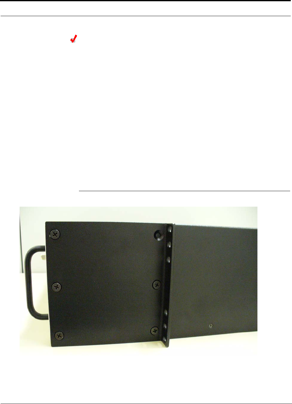
Fusion SingleStar Installation Procedures
6-10 InterReach Fusion SingleStar Installation, Operation, and Reference Manual
CONFIDENTIAL D-620605-0-20 Rev A
Installing a Fusion SingleStar Hub Using the 12” Wall-Mounted
Bracket
Considerations:
• The rack-mounting brackets on the Fusion SS Hub must be moved to the recessed
mounting position to allow for the required 76 mm (3 in.) rear clearance.
• • The maximum weight the bracket can hold is 22.5 kg (50 lbs).
• • The bracket is designed to accommodate a Fusion SS Hub (21 lbs.) and a Smart-
Source Adaptive Processor Unit.
• The wall mount bracket should be securely mounted to wall, using the four key slot
mounting holes on the bracket.
To install the Hub directly to the wall:
1. Attach the wall bracket (PN 4712) to wall the using #10 Pan Head wood screws,
1-1/2” minimum length for mounting in wood studs or 3/4“ thick plywood.
The bracket must be positioned so that the Hub will be in a horizontal position
when it is installed. (Refer to Figure 6-1.)
Figure 6-1 Installing in the Recessed Mounting Position

Help Hot Line (U.S. only): 1-800-530-9960 6-11
D-620605-0-20 Rev A CONFIDENTIAL
Fusion SingleStar Installation Procedures
NOTE: If wall stud spacing of 16” is not available, LGC recommends that
3/4“ plywood be pre-installed to the wall. You can then attach the bracket to
the plywood using the wood screws.
2. Remove both of the rack mounting brackets from the Hub.
3. Reattach each of the rack mounting brackets to the wall mount position.
4. Attach the Hub to the plywood with wood screws.
Installing a Fusion SingleStar Hub Directly to the Wall
To install the Hub directly to the wall:
1. Pre-install 3/4” plywood to the wall.
2. Mount both of the rack mounting brackets using #10-32 machine screws (refer to
illustration Figure 6-2).
3. Attach the Hub to the wall so the mounting brackets are orientated at the top and
bottom of the wall mounted hub.
Use two #10 Pan Head wood screws, 1-1/2” length, to secure each bracket to the
plywood. In this orientation the enclosure fans shall face to the left.
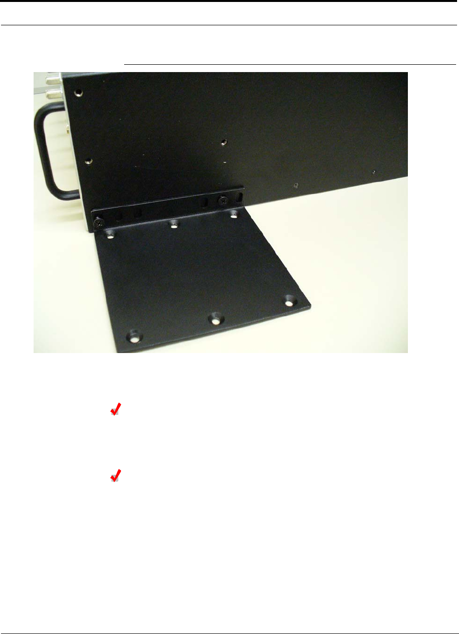
Fusion SingleStar Installation Procedures
6-12 InterReach Fusion SingleStar Installation, Operation, and Reference Manual
CONFIDENTIAL D-620605-0-20 Rev A
Figure 6-2 Mounting of Rack Mounting Brackets for Hub Wall Mounting
Installing an Optional Cable Manager in the Rack
• Using the screws provided, fasten the cable manager to the rack, immediately
above or below the Fusion SingleStar Hub.
Connecting the CATV Cables
Considerations:
• Verify that the cable has been tested and the test results are recorded. This informa-
tion is required for the As-Built Document.
• Verify that only captive centerpin F connectors are used on the solid copper center
conductor CATV cable from CommScope (or equivalent).
• Verify that the CATV cable is labeled with:
• Fusion SingleStar Hub port number being used
• RAU identifier

Help Hot Line (U.S. only): 1-800-530-9960 6-13
D-620605-0-20 Rev A CONFIDENTIAL
Fusion SingleStar Installation Procedures
• Carrier (for multiple operator systems)
To connect the CATV cables:
1. Connect the CATV cables to the F ports according to the labels on the cables.
The STATUS LEDs should be off because the RAUs are not connected at the other
end of the CATV cable.
2. Record which cable you are connecting to which port (that is, from the label on
the cable).
This information is required for the As-Built Document.
3. Tie-off the cables or use the optional cable manager to avoid damaging the con-
nectors because of cable strain.
6.4.1.1 Troubleshooting with Hub LEDs During Installation
• All Fusion SingleStar Hub PORT LEDs, with corresponding RAUs connected,
should indicate Green, which indicates that the RAU is powered on and communi-
cation has been established.
• The Fusion SingleStar Hub STATUS LED should be red if the band has not been
programmed.
Table 6-5 Troubleshooting Fusion SingleStar Hub LEDs During Installation
During
Installation LED State Action Impact
1. Fusion Sin-
gleStar Hub
power is On
and no
RAUs are
connected
POWER Off Check AC power; check that the
Hub power-on switch is on;
replace the Hub.
The Hub is not powering on.
Red Replace the Hub One or more power supplies
are out of specification.
PORT LEDs on but didn’t
blink through all states
Replace the Hub. The Microcontroller is not
resetting properly; flash
memory is corrupted.
PORT Red (60 ppm flashing) Port unusable; replace the Hub
when possible.
Current sensor fault; do not
use the port.
PORT Red Use AdminBrowser to determine
the problem.
The Hub is off-line.

Fusion SingleStar Installation Procedures
6-14 InterReach Fusion SingleStar Installation, Operation, and Reference Manual
CONFIDENTIAL D-620605-0-20 Rev A
2. Fusion Sin-
gleStar Hub
power is On
and RAUs
are con-
nected
PORT Off Check the CATV cable. Power is not getting to the
RAU.
PORT Red (60 ppm flashing) Test the CATV cable. If the cable
tests OK, try another port. If the
second port’s LEDs are Red/Off,
replace the RAU. If the second
RAU doesn’t work; replace the
Fusion SingleStar Hub.
Power levels to the RAU are
not correct; communications
are not established.
If the second port works, flag
the first port as unusable;
replace the Hub when possi-
ble.
Off
PORT Red Use AdminBrowser to determine
the problem.
The RAU is off-line.
Table 6-5 Troubleshooting Fusion SingleStar Hub LEDs During Installation
During
Installation LED State Action Impact

Help Hot Line (U.S. only): 1-800-530-9960 6-15
D-620605-0-20 Rev A CONFIDENTIAL
Fusion SingleStar Installation Procedures
6.4.2 Installing RAUs
CAUTION: Install RAUs in indoor locations only. Do not con-
nect an antenna that is installed in an outdoor location to an RAU.
Installing RAUs
Mount all RAUs in the locations marked on the floor plans.
Considerations:
• Install iDEN and 850/1900 MHz RAUs so that their antennas will be separated by
enough space to reduce signal interference between the two bands. Refer to
Section , “800/850 MHz Isolation Requirements,” on page 6-15 for recommended
distance between antennas.
• You can place the unit, without its fastening hardware, on a flat surface, such as a
shelf, desk, cabinet, or any other horizontal surface that allows stable placement
with the mounting base facing down to the mounting surface. For mounting to
other locations ( that is, walls, ceilings, poles) the RAU must be securely mounted
using the 4 sloted mounting holes provided with #6 diameter fasteners. This
method of mounting must securely hold a minimum of 7 lbs. load.
• Attach the RAU securely to a stationary object (that is, a wall, pole, or ceiling tile).
• For proper ventilation:
• Keep at least 76 mm (3 in.) clearance around the RAU to ensure proper venting.
• Do not stack RAUs on top of each other.
• Always mount the RAU with the solid face against the mounting surface.
Installing Passive Antennas
Refer to the manufacturer’s installation instructions to install passive antennas.
Location
Passive antennas are usually installed below the ceiling. If they are installed above
the ceiling, you must consider the additional loss due to the ceiling material when
estimating the antenna coverage area.
800/850 MHz Isolation Requirements
When deploying any RF system, give special attention to preventing receiver block-
ing or desensitization by out-of-band transmitters. Typically, sharp filters in the
receiver front-end will reduce the interfering transmitters to tolerable levels. In select
cases, the interferers may occupy a frequency band that is directly adjacent to the
receiving band and cannot be adequately rejected by filtering. The only recourse in
these situations is to provide sufficient isolation by physically separating the interfer-
ing transmitters and receivers.
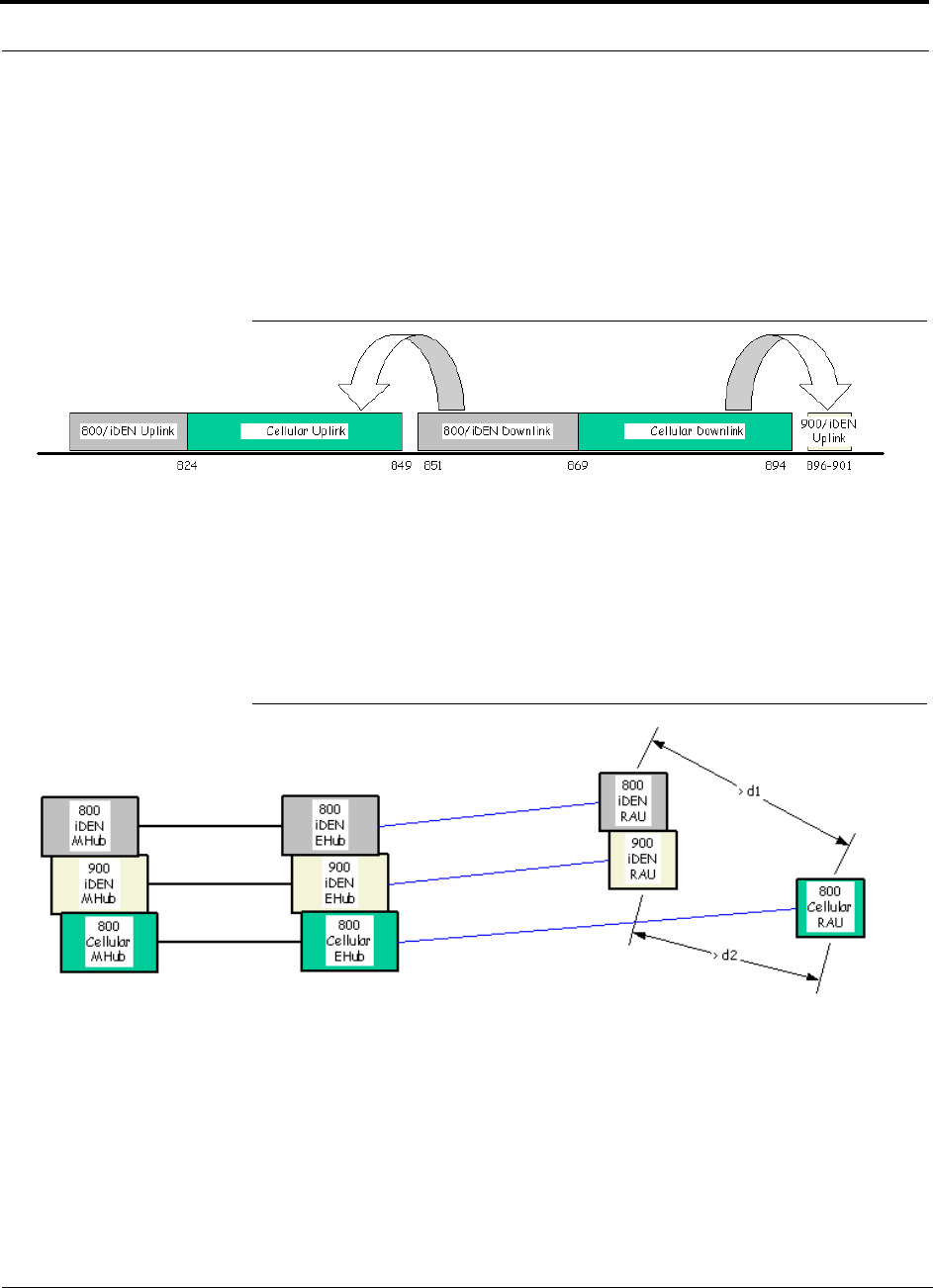
Fusion SingleStar Installation Procedures
6-16 InterReach Fusion SingleStar Installation, Operation, and Reference Manual
CONFIDENTIAL D-620605-0-20 Rev A
iDEN occupies spectrum at both 800 MHz and 900 MHz (Tx:806–825/Rx:851–870
and Tx:896–901/Rx:935–940), while the Cellular A and B carriers share a single 850
MHz block (Tx:869–894/Rx:824–849). The combination of these frequency bands,
800/900 MHz iDEN and 850 MHz Cellular, result in uplink (BTS receive) bands that
are adjacent to downlink (BTS transmit) bands. Figure 6-3 depicts these nearly con-
tiguous bands, with arrows indicating the interfering downlink and receiving uplink
bands.
Figure 6-3 800/850 MHz Spectrum
Installation of an in-building distributed antenna system (DAS) to provide coverage
for both 800/900 MHz iDEN and 850 MHz Cellular must account for these down-
link-to-uplink interference issues and provide adequate isolation.
LGC offers the following guidelines toward achieving the proper amount of isolation
when deploying LGC Wireless Unison DAS products.
Figure 6-4 Guideline for Unison RAU Antenna Placement
800 MHz iDEN Downlink & 850 MHz Cellular Uplink
A 2 MHz frequency gap (851 – 849 MHz) separates the 800 iDEN downlink and 850
Cellular uplink frequency bands. Because of this narrow spacing, 800 iDEN down-
link intermodulation products may fall within the 850 Cellular uplink band. In addi-
tion, 800 iDEN downlink signals near the lower edge of the band at 851 MHz may
cause the 850 Cellular uplink automatic level control (ALC) circuitry in the RAU to
engage and thereby reduce uplink gain.
850 850
Help Hot Line (U.S. only): 1-800-530-9960 6-17
D-620605-0-20 Rev A CONFIDENTIAL
Fusion SingleStar Installation Procedures
To prevent either of these conditions, use the following guidelines:
• In-band 800 iDEN intermodulation products < -90dBm
• Lower frequency 800 iDEN signals < –30dBm for Unison
Given a typical DAS configuration (4 iDEN carriers, omni-directional antennas, line
of sight), these guidelines translate to an antenna spacing (d1) of 6 – 9 meters.
850 MHz Cellular Downlink & 900 MHz iDEN Uplink
A 2 MHz frequency gap (896 – 894 MHz) separates the 850 Cellular downlink and
900 iDEN uplink frequency bands. Because of this narrow spacing, 850 Cellular
downlink intermodulation products may fall within the 900 iDEN uplink band. In
addition, 850 Cellular downlink signals near the upper edge of the band at 894 MHz
may cause the 900 iDEN uplink ALC to engage and thereby reduce uplink gain.
To prevent either of these conditions, use the following guidelines:
• In-band 850 Cellular intermodulation products < -90dBm
• Upper frequency 850 Cellular signals < –30dBm for Unison
Given a typical DAS configuration (6 CDMA carriers for Unison, omni-directional
antennas, line of sight), these guidelines translate to an antenna spacing (d2) of 8-14
meters.
Connecting the Antenna to the RAU
Connect a passive multi-band antenna to the N connector on the RAU using coaxial
cable with the least amount of loss possible.
CAUTION: Firmly hand-tighten the N connector – DO NOT
over-tighten the connector.
Connecting the CATV Cable
Considerations:
• Verify that the cable has been tested and the test results are recorded. This informa-
tion is required for the As-Built Document.
• Verify that only captive centerpin F connectors are used on the solid copper center
conductor CATV 75 Ohm cable.
• Verify that the CATV cable is labeled with:
• Fusion SingleStar Hub port number being used
• RAU identifier
• Carrier (for multiple operator systems)
To connect the CATV cable:

Fusion SingleStar Installation Procedures
6-18 InterReach Fusion SingleStar Installation, Operation, and Reference Manual
CONFIDENTIAL D-620605-0-20 Rev A
1. Connect the CATV cables to the F female port on the RAU according to the label
on the cable.
Power is supplied by the Fusion SingleStar Hub over the CATV cable conductors.
Upon power up, the LEDs will blink for two seconds as a visual check that they
are functioning. After the two-second test:
• The LINK LED should be green indicating it is receiving power and communi-
cations from the Fusion SingleStar Hub.
• The ALARM LED should be red until the Fusion SingleStar Hub issues the band
command, within about 20 seconds, then it should be green.
2. Record which cable you are connecting to the RAU (from the label on the cable).
This information is required for the As-Built Document.
3. Tie-off cables or use the optional cable manager to avoid damaging the connectors
because of cable strain.
6.4.2.1 Troubleshooting Using RAU LEDs During Installation
• The LINK LED should be green and remain green for longer than 90 seconds. The
ALARM LEDs are red when the system band has not been programmed.
Table 6-6 Troubleshooting RAU LEDs During Installation
During
Installation LED State Action Impact
The RAU is connected
to the Fusion Single-
Star Hub, which is
powered on
LINK Off Check CATV cable. No power to the RAU.
ALARM Off
LINK Green • Check CATV cable
• Check Hub LEDs
Refer to page 6-13, item 2 in
Table 6-5.
• Use AdminBrowser to determine the
problem.
The RAU is off-line.
ALARM Red
LINK Red from
green, after
cables are
connected for
60 seconds
• Check CATV cable.
• Check the Hub LEDs.
• Use AdminBrowser to determine the
problem.
No communications
between the RAU and the
Hub.
ALARM Red

Help Hot Line (U.S. only): 1-800-530-9960 6-19
D-620605-0-20 Rev A CONFIDENTIAL
Fusion SingleStar Installation Procedures
6.4.2.2 Installing RAUs in a Multiple Operator System
When installing both iDEN and Cellular systems in parallel, either as dual-band or
multiple operator systems, you must take special provision to assure that the individ-
ual RAUs do not interfere with each other.
The 850/1900 MHz and iDEN RAU’s antennas must be separated by at least 6
meters (20 feet) to assure that the iDEN downlink signals do not interfere with
the Cellular uplink signals.
6.4.3 Configuring the System
Before the system can operate properly, use AdminBrowser to program the Fusion
SingleStar Hub with the frequency bands that are to be distributed. The Hub must be
programmed with the same frequencies as the RAU used.
Considerations:
• The AdminBrowser software, described in the AdminBrowser User Manual
(PN D-620607-0-20), must be running on a PC/laptop.
• Crossover Ethernet cable with male connectors required.
Connecting the PC to the Fusion SingleStar Hub to Run
AdminBrowser
1. Connect the AC power cord to the Hub.
Make sure the Hub is grounded through the ground lug on the AC power and
the frame ground lug as required. The warranty does not cover damage
caused when an ungrounded Hub is powered on.
2. Plug the power cord into an AC power outlet.
3. Verify that all cables are properly connected on the Hub.
4. Turn on the power to the Hub.
All LEDs blink through the power up sequence. At each port where an RAU is
detected (drawing current), the port LEDs lights green. The Fusion SingleStar
STATUS LED should be green. This state indicates the band’s are not programmed
and provides feedback on the status of the RAU connections.
The LEDs blink for 20 seconds as a visual check that they are functioning.
5. Connect the cross-over Ethernet cable to the PC/laptop and then to the RJ-45
100-BASE-T port on the Hub’s front panel.
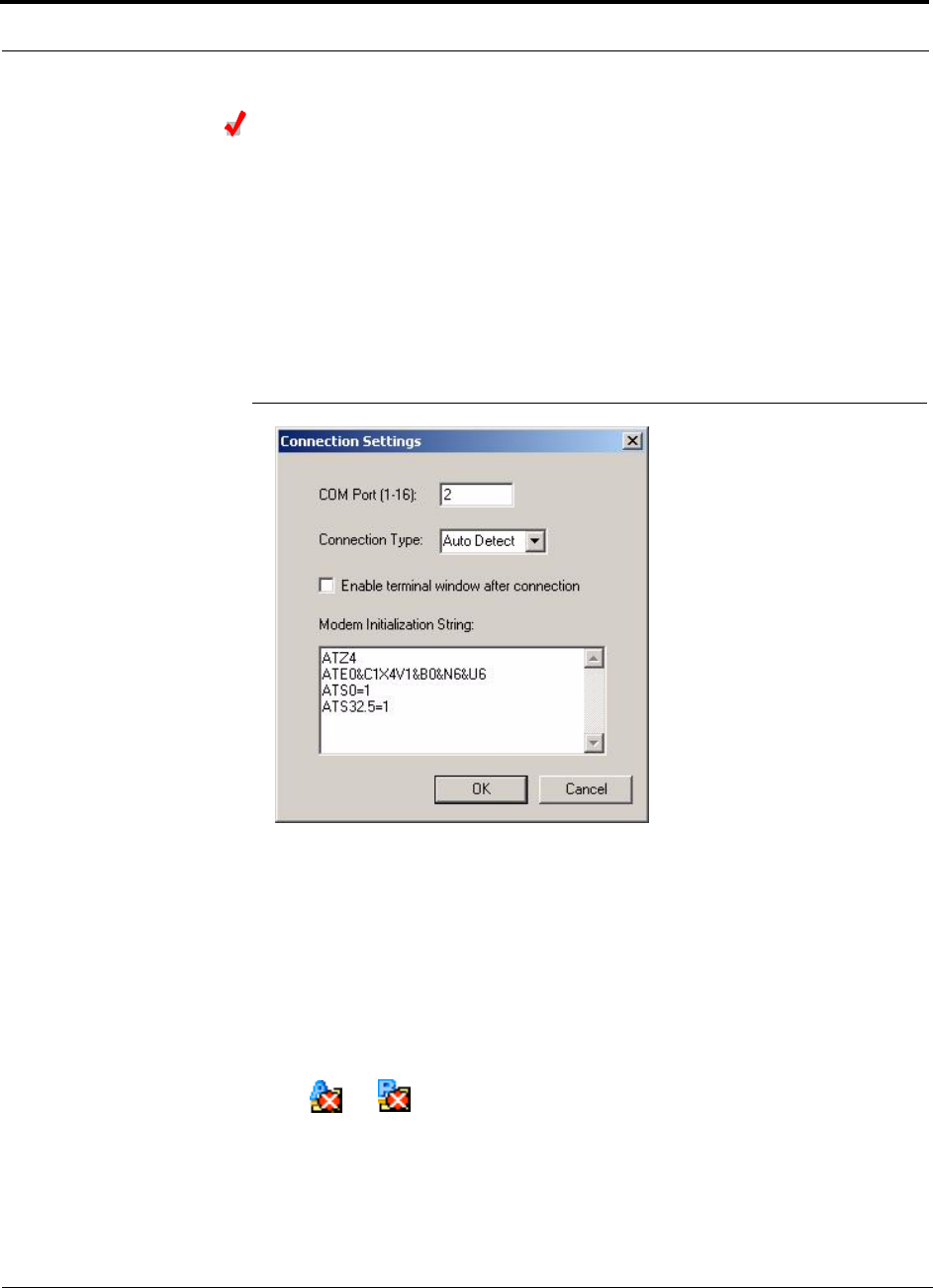
Fusion SingleStar Installation Procedures
6-20 InterReach Fusion SingleStar Installation, Operation, and Reference Manual
CONFIDENTIAL D-620605-0-20 Rev A
Programming the Fusion SingleStar Hub Using AdminBrowser
1. Turn on the PC and start you Internet browser. Type in the AdminBrowser IP
address and press ENTER.
The AdminBrowser main window is displayed.
2. Disable alarm filtering. Use View, Preferences and select “Enable faults, warn-
ings, and status messages.”
3. Select Settings from the Connection menu item.
The Connection Settings dialog box is displayed.
Figure 6-5 Connection Settings Dialog Box
4. Enter the COM Port in the text box.
5. Select the Connection Type from the drop-down menu. LGC recommends using
Auto Detect if unsure.
6. Click OK.
7. Press the Enter key to initiate the connection.
When the connection is made, a hierarchical system tree is displayed in the left
pane of the window. The following icons indicate that the frequency band is not
programmed:
The system tree is not displayed, press F5 key to refresh the tree display.
8. Right-click on the Fusion SingleStar Hub icon and select Install/Configure Sys-
tem.
The System Configuration window is displayed.
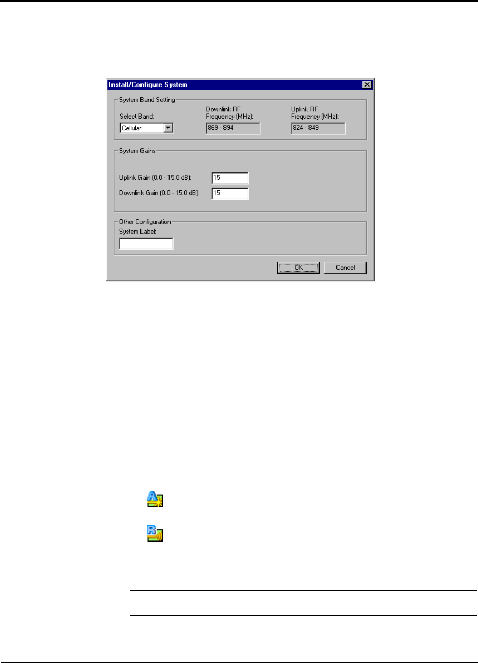
Help Hot Line (U.S. only): 1-800-530-9960 6-21
D-620605-0-20 Rev A CONFIDENTIAL
Fusion SingleStar Installation Procedures
Figure 6-6 System Configuration Window
9. Select the operating bands from the Select Band pull down menu.
The operating bands must match the band of the RAUs that are used in the sys-
tem.
10. Change the System Gain in the text boxes, if desired.
The default is 0 dB for both the uplink and downlink.
11. Change the System Label, if desired.
The default is “Fusion”.
12. Click OK.
During configuration, which can take several minutes for a fully-loaded system
(that is, 8 RAUs), all disconnect status are cleared; the frequency band, gain, and
system label are set; logs are cleared; the system test is performed; and finally the
status tree is refreshed. The icons should be:
Indicating that the bands are correctly set.
Indicating that communications are OK.
If there are problems, the icons are different and a message is displayed in the
Messages pane.
NOTE: Refer to Section 8 for troubleshooting.
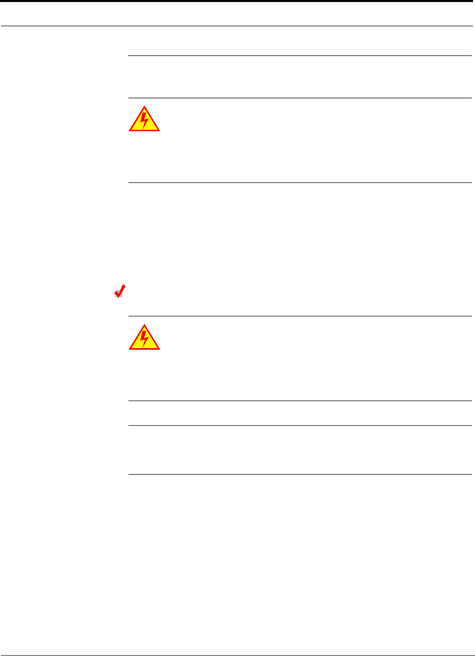
Interfacing the Fusion SingleStar to an RF Source
6-22 InterReach Fusion SingleStar Installation, Operation, and Reference Manual
CONFIDENTIAL D-620605-0-20 Rev A
6.5 Interfacing the Fusion SingleStar to an RF Source
WARNING: Only LGC personnel or LGC-authorized installation per-
sonnel should connect the Fusion SingleStar Hub to its Band associated
base station or repeater. Exceeding the maximum input power could
cause failure of the Fusion SingleStar Hub (refer to Section 5.2 on page 5-4 for
maximum power specifications). If the maximum composite power is too high,
attenuation is required.
6.5.1 Connecting a Single Fusion SingleStar Hub to an RF Source
The Fusion SingleStar system supports two RF sources, one for Band 1 and one for
Band 2. This section explains how each Band can be connected to its associated RF
source.
Connecting a Fusion SingleStar Hub to an In-Building BTS
WARNING: Only LGC personnel or LGC-authorized installation per-
sonnel should connect the Fusion SingleStar Hub to a base station or
repeater. Exceeding the maximum input power could cause failure of
the Fusion SingleStar Hub (refer to Section 5.2 on page 5-4 for maximum power
specifications). If the maximum composite power is too high, attenuation is
required.
CAUTION:The UPLINK and DOWNLINK ports cannot handle a DC power
feed from the base station. If DC power is present, a DC block must be used
or the hub may be damaged.
Connecting a Simplex Base Station to a Fusion SingleStar Hub RF Band:
1. Connect an N-male to N-male coaxial cable to the transmit simplex connector on
the base station.
2. Connect the other end of the N-male to N-male coaxial cable to the DOWNLINK
connector on the Hub for either Band 1 or Band 2.
3. Connect an N-male to N-male coaxial cable to the receive simplex connector on
the base station.
4. Connect the other end of the N-male to N-male coaxial cable to the UPLINK con-
nector on the Hub for either Band 1 or Band 2.
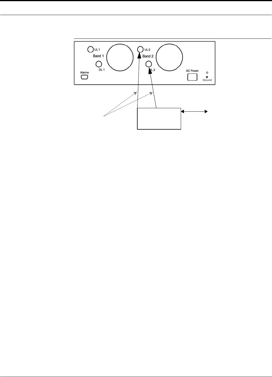
Help Hot Line (U.S. only): 1-800-530-9960 6-23
D-620605-0-20 Rev A CONFIDENTIAL
Interfacing the Fusion SingleStar to an RF Source
Figure 6-7 Simplex Base Station to a Fusion SingleStar Hub
N-male to N-male
Coaxial Cable
Base Station
Simplex T1/E1 to
Mobile
Switching
Center
Insert attenuator, if needed
Note: This applies to either Band 1 or Band 2.
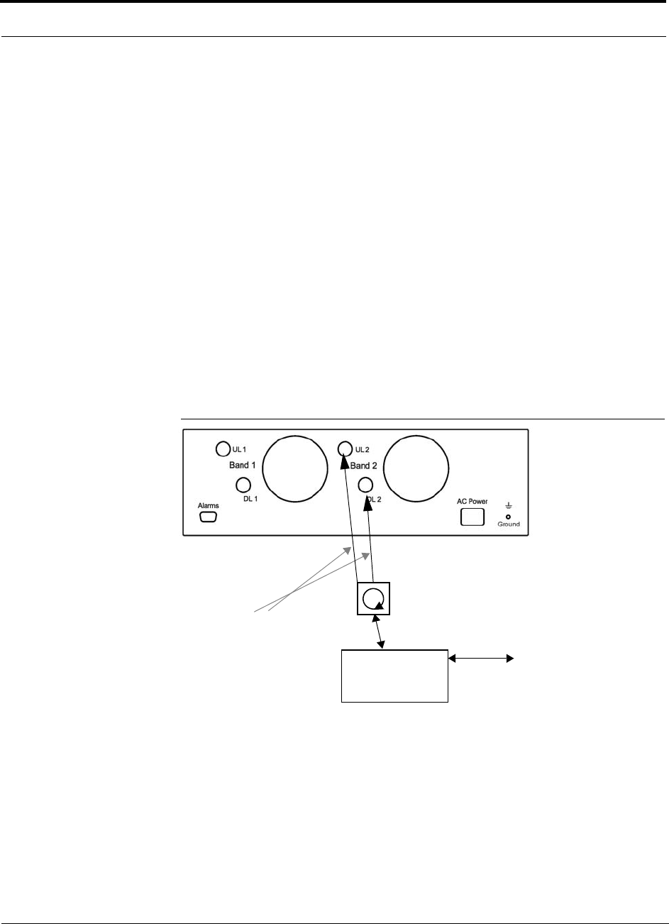
Interfacing the Fusion SingleStar to an RF Source
6-24 InterReach Fusion SingleStar Installation, Operation, and Reference Manual
CONFIDENTIAL D-620605-0-20 Rev A
Connecting a Duplex Base Station to a Fusion SingleStar Hub:
When connecting to a duplex base station, use a circulator or duplexer between it and
the Fusion SingleStar Hub.
You can insert attenuators between the circulator or duplexer and Hub as needed.
1. Connect an N-male to N-male coaxial cable to the duplex connector on the base
station.
2. Connect the other N-male connector or duplexer to a circulator.
3. Connect an N-male to N-male coaxial cable to the DOWNLINK connector on the
Hub for either Band 1 or Band 2.
4. Connect the other end of the N-male coaxial cable to the transmit connector on the
circulator.
5. Connect an N-male to N-male coaxial cable to the UPLINK connector on the Hub
for either Band 1 or Band 2.
6. Connect the other end of the N-male coaxial cable to the receive connector on the
circulator.
Figure 6-8 Duplex Base Station to a Fusion SingleStar Hub
N-male to N-male
Coaxial Cable
Base Station
Duplex T1/E1 to
Mobile
Switching
Center
Insert attenuator, if needed N-male to N-male
Coaxial Cable
Circulator
Note: This applies to either Band 1 or Band 2.
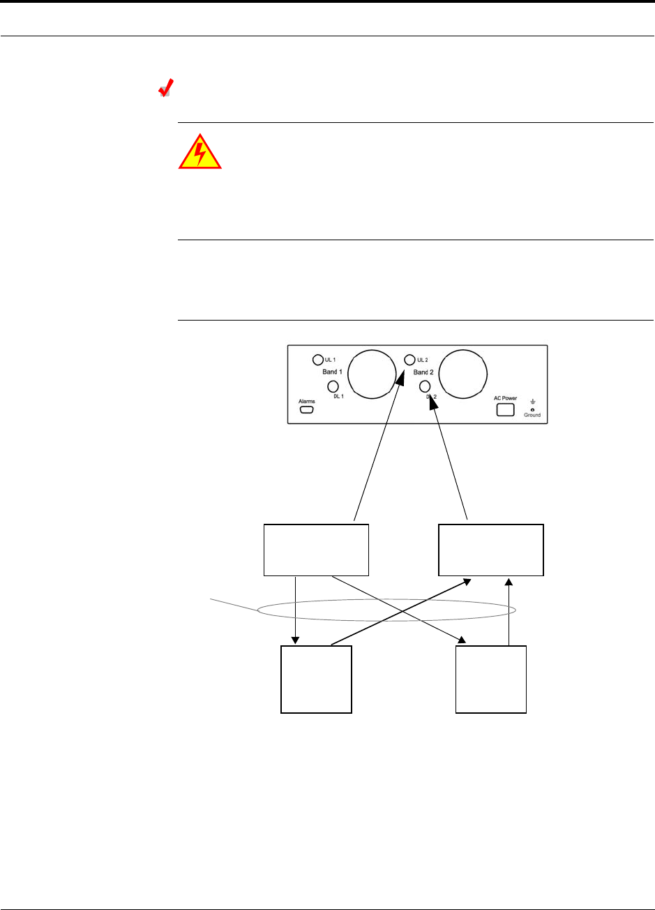
Help Hot Line (U.S. only): 1-800-530-9960 6-25
D-620605-0-20 Rev A CONFIDENTIAL
Interfacing the Fusion SingleStar to an RF Source
Connecting a Fusion SingleStar Hub RF Band to Multiple BTSs
WARNING: Only LGC personnel or LGC-authorized installation per-
sonnel should connect the Fusion SingleStar Hub to a base station or
repeater. Exceeding the maximum input power could cause failure of
the Fusion SingleStar Hub (refer to Section 5.2 on page 5-4 for maximum power
specifications). If the maximum composite power is too high, attenuation is
required.
You can use power combiner/splitters to connect a Fusion SingleStar Hub RF Band to
multiple base stations, as shown in Figure 6-9.
Figure 6-9 Connecting a Fusion SingleStar Hub to Multiple Base Stations
N-male to N-male
Coaxial Jumper Cables
N-male to N-male
Coaxial Jumper Cable
to Repeater or
Base Station
between Combiner/Splitter and
N-male to N-male
Coaxial Jumper Cables
between Combiner/Splitter and
Fusion SingleStar Hub’s Uplink Port Fusion SingleStar Hub’s Downlink P
o
2 x 1 Power
Combiner/Splitter 2 x 1 Power
Combiner/Splitter
BTS 1
UL DL
BTS 2
UL DL
Insert attenuators, if needed
for each on Band 1 or Band 2 either Band 1 or Band 2
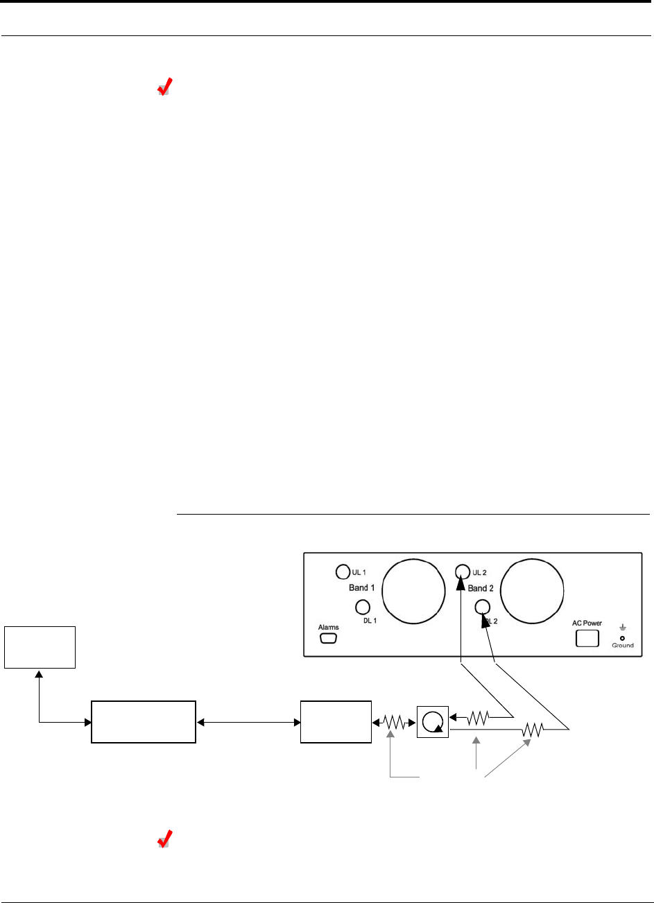
Interfacing the Fusion SingleStar to an RF Source
6-26 InterReach Fusion SingleStar Installation, Operation, and Reference Manual
CONFIDENTIAL D-620605-0-20 Rev A
Connecting a Fusion SingleStar Hub to a Roof-top Antenna
LGC Wireless recommends that you use a lightning arrestor or surge protector in a
roof-top antenna configuration. Insert the lightning arrestor or surge protector
between the roof-top antenna and the repeater connected to the Fusion SingleStar
Hub RF Band.
1. Connect an N-male to N-male coaxial cable to the roof-top antenna.
2. Connect the other end of the N-male to N-male coaxial cable to the grounded
surge suppressor.
3. Connect an N-male to N-male coaxial cable to the grounded surge suppressor.
4. Connect the other end of the N-male to N-male coaxial cable to the repeater.
5. Connect an N-male to N-male coaxial cable to the repeater.
6. Connect the other end of the N-male to N-male coaxial cable to the circulator
1connector.
7. Connect an N-male to N-male coaxial cable to the circulator 2connector.
8. Connect the other end of the N-male to N-male coaxial cable to the DOWNLINK
connector on the Hub for either Band 1 or Band 2.
Attenuation may be required to achieve the desired RF output at the RAU.
9. Connect an N-male to N-male coaxial cable to the circulator 3connector.
10. Connect the other end of the N-male to N-male coaxial cable to the UPLINK con-
nector on the Hub for either Band 1 or Band 2.
Figure 6-10 Connecting a Fusion SingleStar Hub to a Roof-top Antenna
Connecting a Fusion SingleStar Hub to MetroReach Focus
Refer to the MetroReach Focus manual for information.
Roof-top
Antenna
Grounded
Surge Suppressor Repeater
N-male to N-male
Coaxial Cables
N-male to N-male
Coaxial Cable
N-male to N-male
Coaxial Cable Circulator
Attenuator
(optional)
Note: This applies to either Band 1 or Band 2.
Help Hot Line (U.S. only): 1-800-530-9960 6-27
D-620605-0-20 Rev A CONFIDENTIAL
Interfacing the Fusion SingleStar to an RF Source
6.5.2 Connecting Multiple Fusion SingleStar Hubs to an RF Source
You can use power combiner/splitters as splitters to connect multiple Fusion Single-
Star Hubs in order to increase the total number of RAUs in a system. You can also use
power combiner/splitters to combine base station channels in order to increase the
number of RF carriers the system transports.
Connecting Multiple Fusion SingleStar Hubs to a Simplex
Repeater or BTS
WARNING: Only LGC personnel or LGC-authorized installation per-
sonnel should connect the Fusion SingleStar Hub to a base station or
repeater. Exceeding the maximum input power could cause failure of
the Fusion SingleStar Hub (refer to Section 5.2 on page 5-4 for maximum power
specifications). If the maximum composite power is too high, attenuation is
required.
Considerations:
• 2 hybrid power combiner/splitters; one for uplink and one for downlink (2x1 for
two Fusion SingleStar Hubs, 3x1 for three, 4x1 for four, and so on.)
• 1 N-male to N-male coaxial jumper cable between each power combiner/splitter
and the base station
• 2 N-male to N-male coaxial jumper cables between each power combiner/splitter
and each Fusion SingleStar Hub RF Band (either Band 1 or Band 2)
Procedure:
1. Connect the power combiner/splitters to the repeater or base station using N-male
to N-male coaxial jumper cables:
a. From the first power combiner/splitter to the repeater or base station UPLINK
b. From the second power combiner/splitter to the repeater or base station
DOWNLINK
2. Connect the power combiner/splitters to the Hubs:
a. From the first Hub’s UPLINK port (Band 1 or Band 2) to the first power com-
biner/splitter
b. From the first Hub’s DOWNLINK port (Band 1 or Band 2) to the second power
combiner/splitter
c. From the second Hub’s UPLINK port (Band 1 or Band 2) to the first power
combiner/splitter
d. From the second Hub’s DOWNLINK port (Band 1 or Band 2) to the second
power combiner/splitter

Interfacing the Fusion SingleStar to an RF Source
6-28 InterReach Fusion SingleStar Installation, Operation, and Reference Manual
CONFIDENTIAL D-620605-0-20 Rev A
NOTE: Connections should not cross Bands. For example, all Band 1 connections
should be made to the same hybrid power combiner/splitter connected to the repeater
BTS that matches the Band 1 frequency.
3. Check Hub LEDs.
After connecting and powering on the Hub, check all LEDs to ensure that the sys-
tem is operating properly.
Make sure the Hub is grounded. The warranty does not cover damage caused
when an ungrounded Hub is powered on.
NOTE: Use a 50 ohm terminator on any unused power combiner/splitter ports.
Figure 6-11 shows how to connect two Hubs to a simplex repeater or base station.
Connecting two Hubs increases the total number of supportable RAUs from 8 to 16.
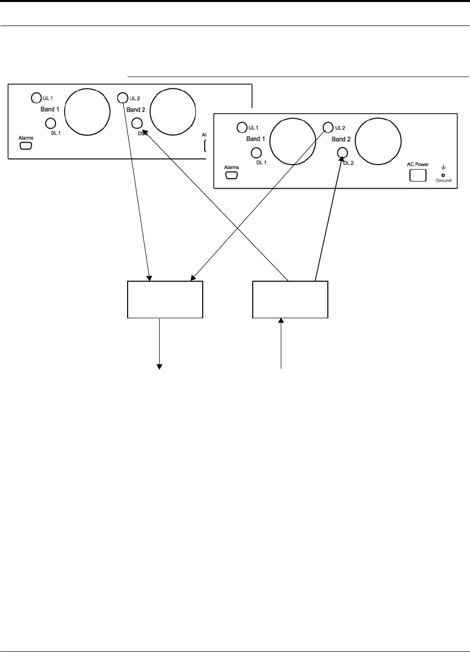
Help Hot Line (U.S. only): 1-800-530-9960 6-29
D-620605-0-20 Rev A CONFIDENTIAL
Interfacing the Fusion SingleStar to an RF Source
Figure 6-11 Connecting Two Fusion SingleStar Hub’s RF Band Ports to a
Simplex Repeater or Base Station
N-male to N-male
Coaxial Jumper Cables
N-male to N-male
Coaxial Jumper Cable
to Repeater or
Base Station
2 x 1 Power
Combiner/Splitter
N-male to N-male
Coaxial Jumper Cable
to Repeater or
Base Station
between Combiner/Splitter and
N-male to N-male
Coaxial Jumper Cables
between Combiner/Splitter and
o
n SingleStar Hub’s Uplink Port for Fusion SingleStar Hub’s Downlink Por
t
2 x 1 Power
Combiner/Splitter
either Band 1 or Band 2 either Band 1 or Band 2

Interfacing the Fusion SingleStar to an RF Source
6-30 InterReach Fusion SingleStar Installation, Operation, and Reference Manual
CONFIDENTIAL D-620605-0-20 Rev A
Connecting Multiple Fusion SingleStar Hubs to a Duplex
Repeater or BTS
WARNING: Only LGC personnel or LGC-authorized installation per-
sonnel should connect the Fusion SingleStar Hub to a base station or
repeater. Exceeding the maximum input power could cause failure of
the Fusion SingleStar Hub (refer to Section 5.2 on page 5-4 for maximum power
specifications). If the maximum composite power is too high, attenuation is
required.
Considerations:
• 2 hybrid power combiner/splitters; one for uplink and one for downlink (2x1 for
two Fusion SingleStar Hubs, 3x1 for three, 4x1 for four, and so.)
• 2 N-male to N-male coaxial jumper cables to connect each Fusion SingleStar
Hub’s RF Band to the power combiner/splitters
• 1 circulator
• 1 N-male to N-male coaxial jumper cable between each circulator and the repeater
or base station
• 1 N-male to N-male coaxial jumper cable between each circulator and power com-
biner/splitter
Procedure:
1. Connect the circulator to the repeater or base station using one N-male to N-male
coaxial jumper cable.
2. Connect each power combiner/splitter to the circulator using one N-male to
N-male coaxial jumper cable per combiner/splitter.
3. Connect the power combiner/splitter to the Hubs using N-male to N-male coaxial
jumper cable:
a. From the first Hub’s UPLINK (Band 1 or Band 2) port to the first power com-
biner/splitter
b. From the first Hub’s DOWNLINK (Band 1 or Band 2) port to the second power
combiner/splitter
c. From the second Hub’s UPLINK (Band 1 or Band 2) port to the first power
combiner/splitter
d. From the second Hub’s DOWNLINK (Band 1 or Band 2) port to the second
power combiner/splitter
NOTE: Connections should not cross Bands. For example, all Band 1 connections
should be made to the same hybrid power combiner/splitter connected to the repeater
BTS that matches the Band 1 frequency.
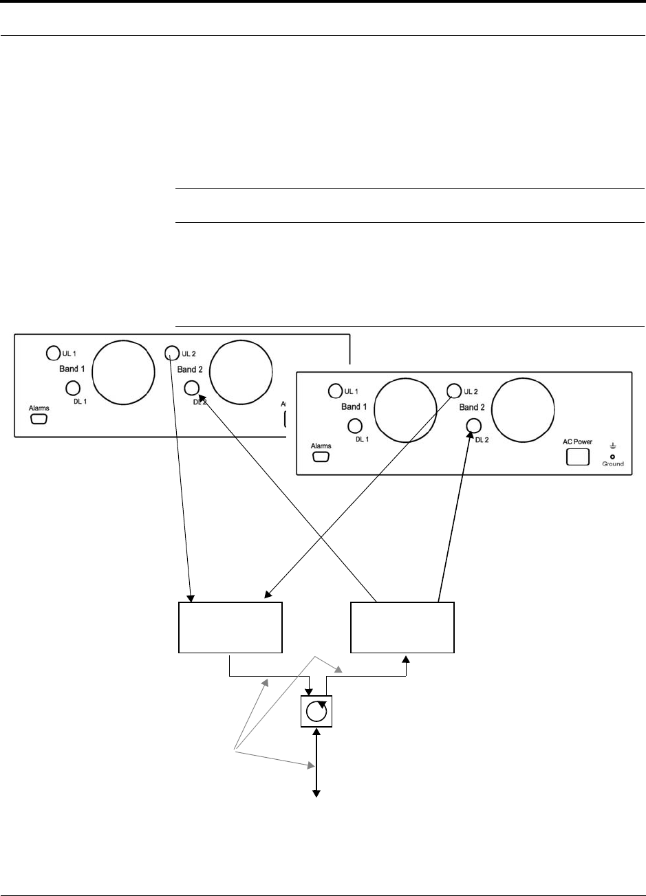
Help Hot Line (U.S. only): 1-800-530-9960 6-31
D-620605-0-20 Rev A CONFIDENTIAL
Interfacing the Fusion SingleStar to an RF Source
4. Check Hub LEDs.
After connecting and powering on the Hub, check all LEDs to ensure that the sys-
tem is operating properly.
Make sure the Hub is grounded. The warranty does not cover damage caused
when an ungrounded Hub is powered on.
NOTE: Use a 50 ohm terminator on any unused power combiner/splitter ports.
Figure 6-12 shows how to connect two Hubs to a duplex repeater or base station. You
need to use one circulator and one more coaxial jumper cable, as shown.
Figure 6-12 Connecting Two Fusion SingleStar Hub’s RF Band Ports to a
Duplex Repeater or Base Station
N-male to N-male
Coaxial Jumper Cables
2 x 1 Power
Combiner/Splitter
between Combiner/Splitter and
N-male to N-male
Coaxial Jumper Cables
between Combiner/Splitter and
usion SingleStar Hub’s Uplink Port Fusion SingleStar Hub’s Downlink P
o
2 x 1 Power
Combiner/Splitter
N-male to N-male
Coaxial Jumper Cable
N-male to N-male
Coaxial Jumper Cable
Circulator
N-male to N-male
Coaxial Jumper Cable
to Repeater or
Base Station
Insert attenuator, if needed
for either Band 1 or Band 2 either Band 1 or Band 2
Port

Connecting Contact Alarms to a Fusion SingleStar System
6-32 InterReach Fusion SingleStar Installation, Operation, and Reference Manual
CONFIDENTIAL D-620605-0-20 Rev A
6.6 Connecting Contact Alarms to a Fusion SingleStar
System
The Fusion SingleStar Hub can generate (source) two contact alarms as well as sense
three external contact alarm.
• Alarm Source (refer to Section 6.6.1 on page 6-33)
The Fusion SingleStar Hub has two alarm contacts, fault (major) and warning
(minor). These contacts are normally-closed (NC) and will open when an internal
alarm is detected.
NOTE: The contact can be changed to normally-open (NO) with Admin-
Browser. This is not recommended since no alarm would be sent if power to
the Fusion SingleStar Hub fails.
• Fault is activated when any faults or disconnects are detected.
• Warning is activated when any warning conditions are detected except lockout
or when the end-to-end system test is not valid.
• Alarm Sense (refer to Section 6.6.2 on page 6-36)
The Fusion SingleStar Hub can monitor a 3 external alarm contacts. Each port can
be configured for normally-open (NO) or normally-closed (NC) contacts. The
interface expects a set of floating contacts, and an external voltage source is not
required for this interface. Use AdminBrowser to monitor the port status.
Table 6-7 lists the alarm types, equipment to which the Fusion SingleStar is con-
nected, cable(s) used, and the faults and warnings that are detected.
Table 6-7 Alarm Types
Note that LGCell, Unison, and MetroReach Focus support only faults (major errors).
Alarm
Type
Fusion
SingleStar
Connected to Cable(s) Used Errors Detected
Source MetroReach 5-port Alarm Daisy-Chain Cable Faults
Source BTS 5-port Alarm Daisy-Chain Cable Faults and Warnings
In addition, a custom daisy-chain cable-to-BTS interface
cable is required. Make this interface cable to the desired
length and with the appropriate pin placement.
Sense LGCell/Unison 5-port Alarm Daisy-Chain Cable
and the Alarm Sense Adapter
Cable
Faults
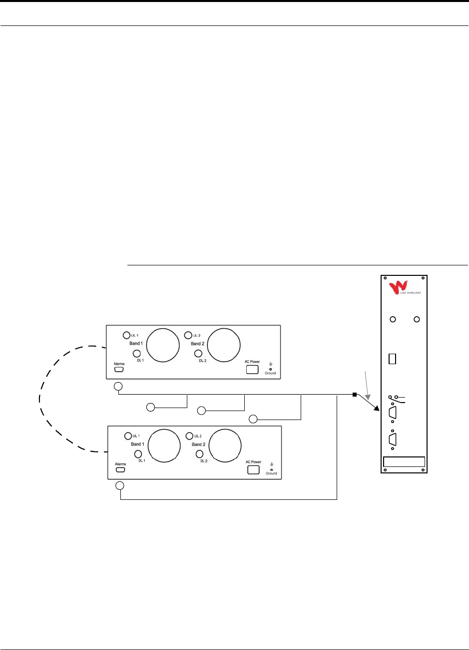
Help Hot Line (U.S. only): 1-800-530-9960 6-33
D-620605-0-20 Rev A CONFIDENTIAL
Connecting Contact Alarms to a Fusion SingleStar System
Do not mix LGCell, Unison, and Fusion SingleStar Hubs in the same daisy-chain.
You can daisy-chain multiple LGCell Main Hubs or Unison Hubs together and use
the Alarm Sense Adapter Cable to connect the chain to a Fusion SingleStar Hub,
which will act as an alarm sensor.
6.6.1 Alarm Source
Fusion SingleStar always acts as an alarm source, no matter what type of equipment
you are connecting to. Refer to Section 6.6.2 on page 6-36 if you want Fusion Single-
Star to sense Unison or LGCell contact closures or other external alarms.
Using MetroReach Focus to Monitor Fusion SS
When you connect MetroReach Focus to the Fusion SS, the Fusion SingleStar Hub is
the output of the alarms (alarm source) and Focus is the input (alarm sense), as shown
in Figure 6-13. Focus supports only faults (major errors).
Figure 6-13 Connecting MetroReach to Fusion SS
RF OUT
DOWNLINK RF IN
UPLINK
FIBER
UPLINK
DOWNLINK
ALARM
RS-232C
MetroReach
Focus
RFM
Alarm
Sense
Alarm
Source
Alarm
Source
5-port Alarm Daisy-Chain Cable
May need
9-pin Adapter,
which ships
with the cable
Fusion SingleStar Hub
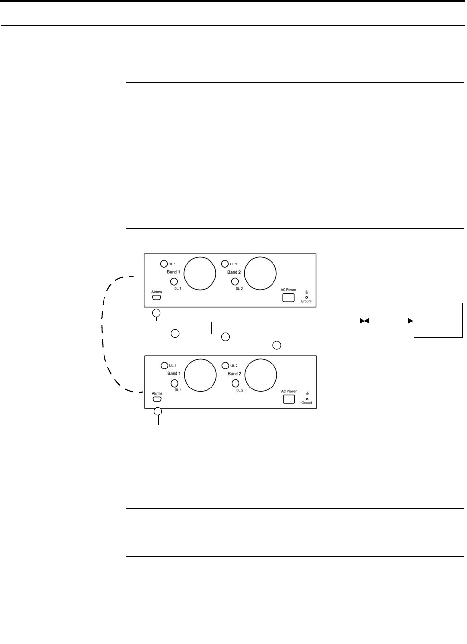
Connecting Contact Alarms to a Fusion SingleStar System
6-34 InterReach Fusion SingleStar Installation, Operation, and Reference Manual
CONFIDENTIAL D-620605-0-20 Rev A
Using a Base Station to Monitor Fusion SS
NOTE: The BTS must be configured, by the carrier, for contact closure monitoring
prior to connecting a Fusion SingleStar Hub to it.
When you connect a BTS to Fusion SS, the Fusion SingleStar Hub is the output of the
alarms (alarm source) and the BTS is the input (alarm sense), as shown in
Figure 6-14. An interface cable is required between the daisy-chain cable and the
BTS. Because BTS alarm interface pinouts and Fusion SS-to-BTS distances vary, this
cable is often custom and wired on-site. Refer to Section 3.2.1 for Alarm Contact
details (Normally Closed).
Figure 6-14 Using a BTS to Monitor Fusion SS
NOTE: For normally open contacts, the fault and warning contacts need to
be wired in parallel with other Main Hubs.
NOTE: LGC Wireless does not recommend using normally open contacts.
BTS
Interface
Cable
Alarm
Sense
Alarm
Source
Alarm
Source
5-port Alarm Daisy-Chain Cable
Fusion SingleStar Hub
(custom made, on-site)
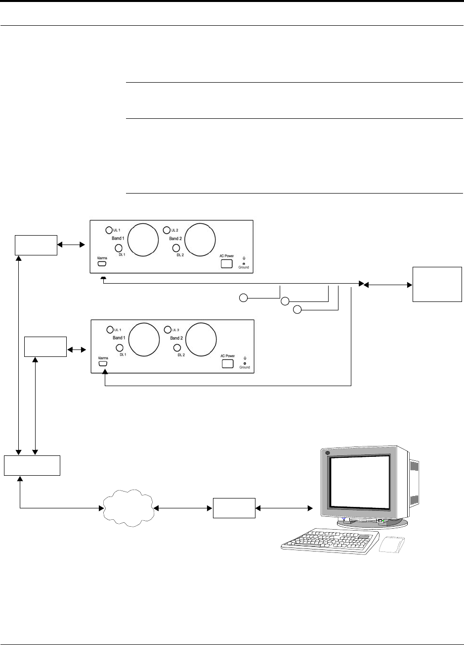
Help Hot Line (U.S. only): 1-800-530-9960 6-35
D-620605-0-20 Rev A CONFIDENTIAL
Connecting Contact Alarms to a Fusion SingleStar System
Using a Base Station and AdminBrowser to Monitor Fusion SS
NOTE: The BTS must be configured, by the carrier, for contact closure monitoring
prior to connecting a Fusion SingleStar Hub to it.
In order to take full advantage of Fusion SS’s OA&M capabilities you can use LGC
Wireless’ AdminBrowser software in addition to a BTS to monitor the system, as
shown in Figure 6-15.
Figure 6-15 Using a BTS and AdminBrowser to Monitor Fusion SS
Line Switch
Straight-through modem cable connected
to Fusion SingleStar Hub’s front panel serial port
PSTN Modem
PC running
Standard Browser
Software
BTS
Interface
Cable
Alarm
Sense
Alarm
Source
Alarm
Source
5-port Alarm Daisy-Chain Cable
Fusion Hub
Modem
Modem
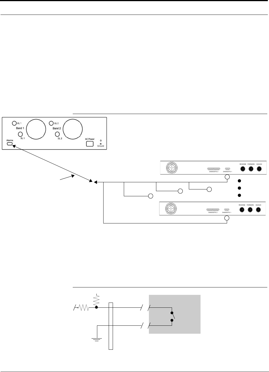
Connecting Contact Alarms to a Fusion SingleStar System
6-36 InterReach Fusion SingleStar Installation, Operation, and Reference Manual
CONFIDENTIAL D-620605-0-20 Rev A
6.6.2 Alarm Sense
Use AdminBrowser to enable the Fusion SingleStar system for “alarm sense” when
connecting to the contact closure of LGCell Main Hubs or other external alarms (refer
to Set Contact Sense Properties in the AdminBrowser User Manual).
Using Fusion SingleStar to Monitor LGCells
When you connect LGCell to Fusion SS, the Fusion SingleStar Hub is the input of the
alarms (alarm sense) and the LGCell is the output (alarm source), as shown in
Figure 6-16. The input alarm sense needs to be set to normally closed (NC).
Figure 6-16 Using Fusion SingleStar to Monitor LGCell or Unison
LGCell or Unison supports only faults. You must use the Alarm Sense Adapter Cable
(refer to page 6-38) to interface the daisy-chain cable to Fusion SS. The adapter cable
is required because it translates the LGCell fault pinout to the sense input pins on the
Fusion SingleStar Hub.
Figure 6-17 Alarm Sense Contacts
Up to 5 LGCell (Unison) Main Hubs
Fusion SingleStar Hub
Alarm
Sense Alarm
Source
Alarm
Source
Alarm Sense
Adapter Cable
5-port Alarm Daisy-Chain Cable
8
1
Diagnostic I
External
Equipment
Contacts
+5V
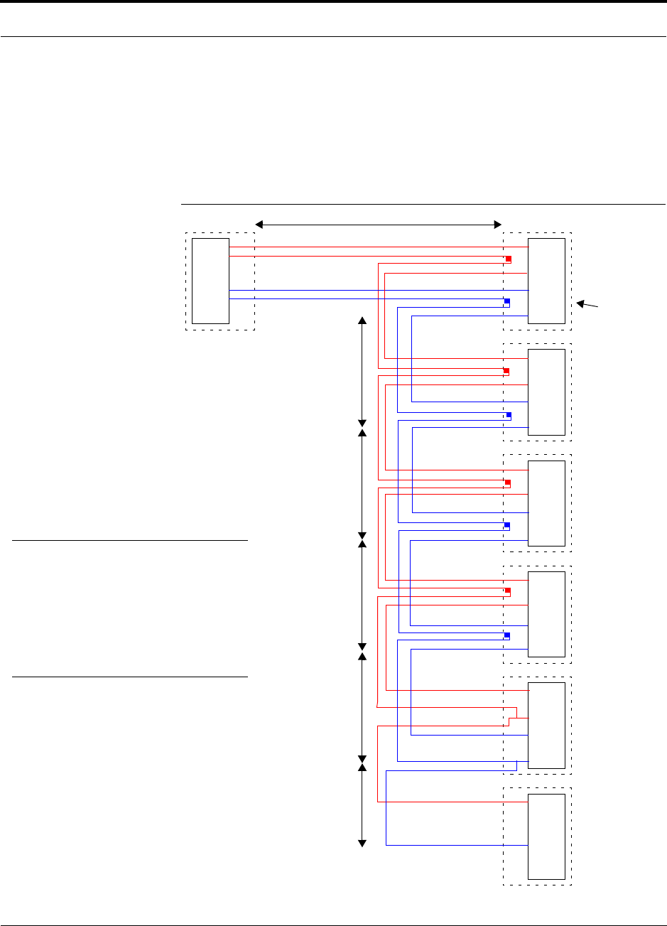
Help Hot Line (U.S. only): 1-800-530-9960 6-37
D-620605-0-20 Rev A CONFIDENTIAL
Connecting Contact Alarms to a Fusion SingleStar System
6.6.3 Alarm Cables
5-port Alarm Daisy-Chain Cable
Figure 6-18 shows the 5-port Alarm Daisy-Chain Cable (PN 4024-3), which supports
fault and warning conditions.
Figure 6-18 5-port Alarm Daisy-Chain Cable
DB-9 female to
Base Station,
MetroReach Focus,
or
J1
Female J2
Male
J3
Male
J4
Male
J5
Male
J6
Male
J7
Female
Terminator
Splice
Splice
Splice
Splice
Splice
Splice
Splice
Splice
7
9
4
5
7
9
4
5
7
9
4
5
7
9
4
5
7
9
4
5
7
4
1.2 meters (4 feet)
.5 meter
(1.5 feet)
DB-9 male to Fusion,
Unison, MetroReach
Focus, or LGCell
Alarm Port
DB-9 male to Fusion,
Unison, MetroReach
Focus, or LGCell
Alarm Port
DB-9 male to Fusion,
Unison, MetroReach
Focus, or LGCell
Alarm Port
DB-9 male to Fusion,
Unison, MetroReach
Focus, or LGCell
Alarm Port
Option 1: DB-9 to Fusion,
Unison, MetroReach
Focus, or LGCell
Alarm Port.
J7 not used
Option 2: Use J2-J5
for alarm ports. J6 is used
to connect to an additional
Alarm Daisy-Chain Cable.
J7 is not used.
Option 3: Connect
fewer than 5 ports and
terminate the daisy chain
by connecting J7 to the
lowest unused port.
Connector
Hood
.5 meter
(1.5 feet)
.5 meter
(1.5 feet)
.5 meter
(1.5 feet)
.25 meter
(.75 feet)
the Alarm Sense
Adapter Cable when
connecting LGCell
NOTE: Do not daisy-chain Fusion
SingleStar Hubs with LGCell or
MetroReach Focus if you want both
faults and warnings from Fusion. Only
faults are reported if you combine
Fusion SingleStar with LGCell or
MetroReach in the same daisy chain.
to Unison
7
9
4
5
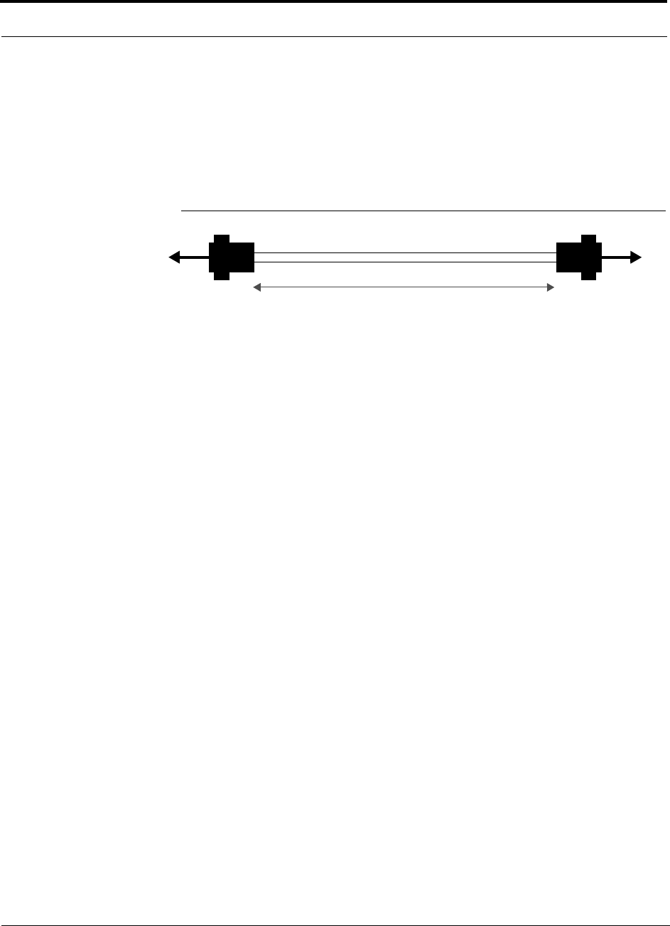
Connecting Contact Alarms to a Fusion SingleStar System
6-38 InterReach Fusion SingleStar Installation, Operation, and Reference Manual
CONFIDENTIAL D-620605-0-20 Rev A
Alarm Sense Adapter Cable
The alarm sense adapter cable (PN 4025-1) translates the LGCell fault pinout to the
sense input pins on the Fusion SingleStar Hub. You must use this adapter cable, illus-
trated in Figure 6-19, with the 5-port Alarm Daisy-Chain Cable when connecting
LGCell to Fusion SS.
Figure 6-19 Alarm Sense Adapter Cable
J8
1
8
J9
7
9
To Fusion To Daisy-Chain Cable
3 feet
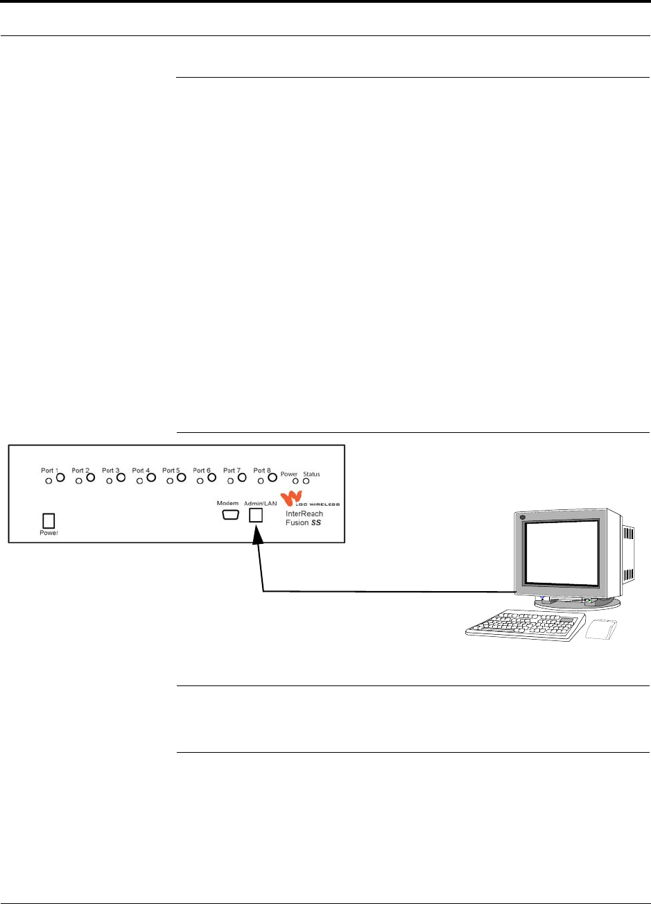
Help Hot Line (U.S. only): 1-800-530-9960 6-39
D-620605-0-20 Rev A CONFIDENTIAL
Alarm Monitoring Connectivity Options
6.7 Alarm Monitoring Connectivity Options
The following connectivity options are described:
• Section 6.7.1 Direct Connection . . . . . . . . . . . . . . . . . . . . . . . . . . . . . . . . . . . 6-39
• Section 6.7.2 Modem Connection . . . . . . . . . . . . . . . . . . . . . . . . . . . . . . . . . . 6-40
• Section 6.7.3 100 BASE-T Port Expander Connection . . . . . . . . . . . . . . . . . 6-41
• Section 6.7.4 POTS Line Sharing Switch Connection . . . . . . . . . . . . . . . . . . 6-42
• Section 6.7.5 Ethernet LAN Connection . . . . . . . . . . . . . . . . . . . . . . . . . . . . . 6-44
• Section 6.7.6 SNMP Interface . . . . . . . . . . . . . . . . . . . . . . . . . . . . . . . . . . . . . 6-45
Note that the only accessory available through LGC Wireless is the Ethernet
cross-over 100 BASE-T cable, which is provided with AdminBrowser.
6.7.1 Direct Connection
In this configuration, the PC connects directly to the RJ-45 100 BASE-T port on the
Fusion SingleStar Hub’s front panel using a cross-over cable.
Figure 6-20 OA&M Direct Connection
NOTE: The cross-over cable provided with the Fusion SingleStar Hub sup-
ports full hardware handshaking, which is required. Refer to Appendix A.4
on page A-3 for cable wiring information.
PC running
Software
Cross-over 100 BASE-T Cable
Standard Browser
AdminBrower is resident
in Fusion SS.
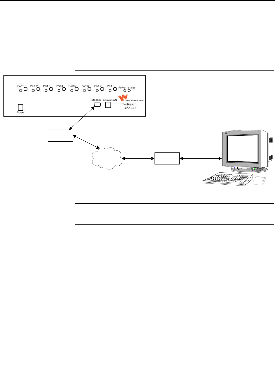
Alarm Monitoring Connectivity Options
6-40 InterReach Fusion SingleStar Installation, Operation, and Reference Manual
CONFIDENTIAL D-620605-0-20 Rev A
6.7.2 Modem Connection
In this configuration, the PC and the Fusion SingleStar Hub connect to modems and
communicate using a standard dial-up telephone connection.
Figure 6-21 OA&M Modem Connection
NOTE: Refer to Appendix A.3 on page A-3 for the modem cable wiring informa-
tion.
Straight-through
modem cable
PC running
Software
Standard Browser
Modem
Straight-through modem cable
PSTN Modem
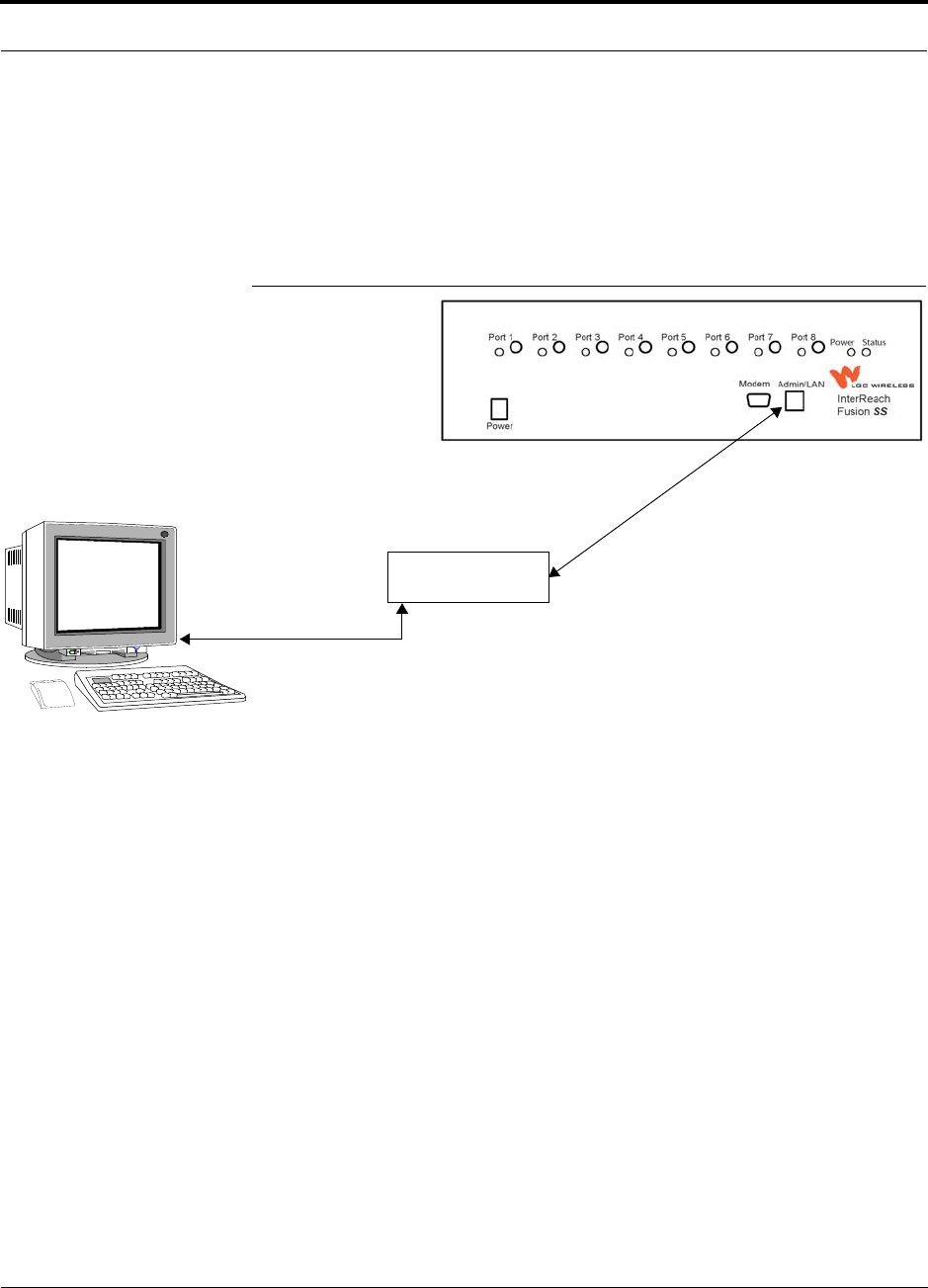
Help Hot Line (U.S. only): 1-800-530-9960 6-41
D-620605-0-20 Rev A CONFIDENTIAL
Alarm Monitoring Connectivity Options
6.7.3 100 BASE-T Port Expander Connection
In this configuration a LAN switch is used to allow the connection of multiple
devices to a single PC with a 100 BASE-T port. Testing was performed with a Link-
sys 4-port switch. A standard RJ-45 Ethernet cable must be made to connect the LAN
switch to the Fusion SingleStar Hub.
Figure 6-22 OA&M Connection using a 232 Port Expander
LAN switch
100 BASE-T Ethernet connection
RJ-45 male to RJ-45 male
100 BASE-T Cable
PC running
Software
Standard Browser
AdminBrowser software is resident
in Fusion SS.
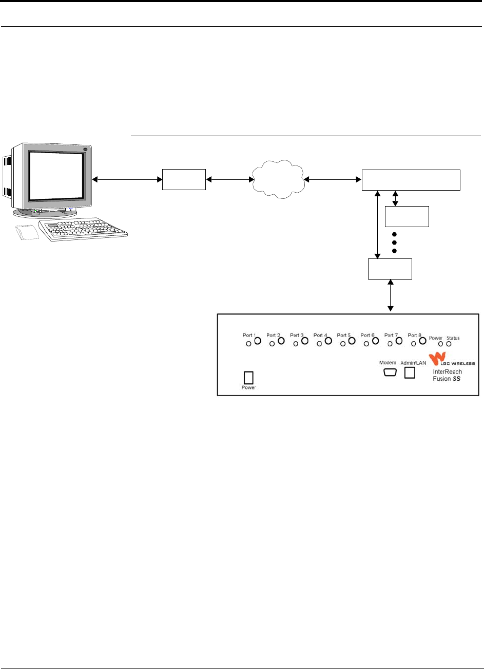
Alarm Monitoring Connectivity Options
6-42 InterReach Fusion SingleStar Installation, Operation, and Reference Manual
CONFIDENTIAL D-620605-0-20 Rev A
6.7.4 POTS Line Sharing Switch Connection
Using a line sharing switch, you can connect up to four modems to a single telephone
line. Testing was performed with a Teltone Line Sharing Switch, model number
M-394-B-01.
Figure 6-23 OA&M Connection Using a POTS Line Sharing Switch
Up to 16 modems can be monitored using a single telephone line by cascading line
sharing switches, as shown in Figure 6-24.
Modem
PSTN
Line Sharing Switch
Up to 4 modems
per Switch
Modem
Modem
Straight-through
modem cable
Straight-through
modem cable
PC running
Software
Standard Browser
Standard phone cable
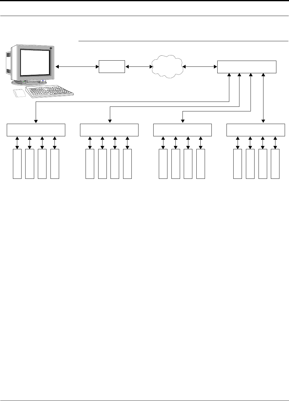
Help Hot Line (U.S. only): 1-800-530-9960 6-43
D-620605-0-20 Rev A CONFIDENTIAL
Alarm Monitoring Connectivity Options
Figure 6-24 Cascading Line Sharing Switches
Modem
PSTN
Line Sharing Switch
Line Sharing Switch Line Sharing Switch Line Sharing Switch Line Sharing Switch
M
o
d
e
m
M
o
d
e
m
M
o
d
e
m
M
o
d
e
m
M
o
d
e
m
M
o
d
e
m
M
o
d
e
m
M
o
d
e
m
M
o
d
e
m
M
o
d
e
m
M
o
d
e
m
M
o
d
e
m
M
o
d
e
m
M
o
d
e
m
M
o
d
e
m
M
o
d
e
m
Straight-through
modem cable
Straight-
through
modem
cables
PC running
Software
Standard Browser
Standard phone cable
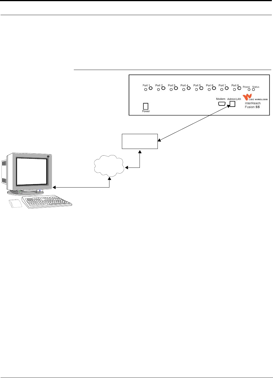
Alarm Monitoring Connectivity Options
6-44 InterReach Fusion SingleStar Installation, Operation, and Reference Manual
CONFIDENTIAL D-620605-0-20 Rev A
6.7.5 Ethernet LAN Connection
An Ethernet LAN connection can be used to communicate between the PC and
Fusion SS. Testing was performed with an Linksys 4-port LAN switch.
Figure 6-25 OA&M Connection Using Ethernet and ENET/232 Serial Hub
LAN
Switch
TCP/IP
Ethernet
100 BASE-T Cable
RJ-45 to RJ-45 male
Ethernet
PC running
Software
Standard Browser
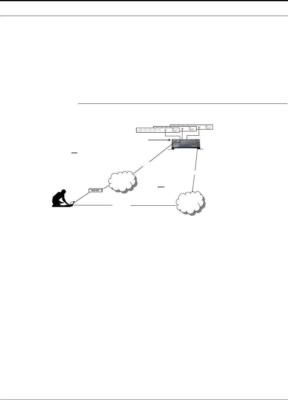
Help Hot Line (U.S. only): 1-800-530-9960 6-45
D-620605-0-20 Rev A CONFIDENTIAL
Alarm Monitoring Connectivity Options
6.7.6 SNMP Interface
Faults and warnings can also be diagnosed with SNMP using a standard network
management system (NMS). SNMP resident in Fusion SingleStar provides complete
SNMP interactions, that is, Gets, Sets, and Traps/Notification.
The Fusion SingleStar SNMP includes a MIB for integrating into the Network Man-
agement System (NMS) and supports SNMPv1 and SNMPv2c.
Figure 6-26 Fusion SingleStar SNMP Configuration Options
The NIU supports
SNMP access to
Unison / Accel systems
via Ethernet or dialup
Modem
Can dedicate one
port for an external
modem
Network
Management
System (SNMP
Manager)
Up to 10 Unison / Accel systems 1
OR
PPP /
POTS
PPP /
POTS
Phone Line
Secure
TCP/IP
Network
Secure
TCP/IP
Network
Ethernet
Ethernet
Network
Interface Unit
(SNMP Proxy
Agent)
1 NIU-10P-NM-1 supports up to 10 Unison/Accel systems
NIU-4P-NM-1 supports up to 4 Unison/Accel systems (not expandable)
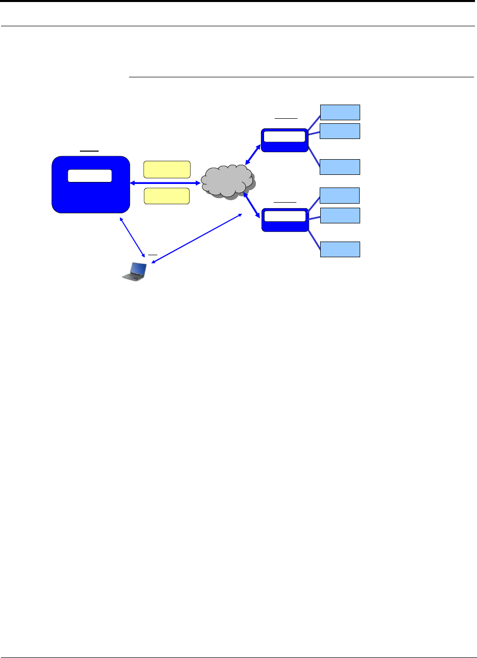
Alarm Monitoring Connectivity Options
6-46 InterReach Fusion SingleStar Installation, Operation, and Reference Manual
CONFIDENTIAL D-620605-0-20 Rev A
Figure 6-27 Multiple Unison Systems Monitored by a Single Network
Management System
SNMP Reply or
Trap / Notification
SNMP Network
Management System
LGC MIB
SNMP v1/v2C
Get or Set
TCP/IP
Network
TCP/IP
Network
>
…
>
…
Site 1
NOC
NIU 2
SNMP Agent
>
…
Site 2
Unison 10
NIU 1
SNMP Agent Unison 2
Unison 10
Unison 1
Unison 2
Unison 1
Troubleshoot via SNMP
(VPN into NMS) Troubleshoot via AdminManager
(Telnet/VPN or PPP/Dialup into NIU)
Field Technician
For Troubleshooting….
OR

InterReach Fusion SingleStar Installation, Operation, and Reference Manual 7-1
D-x620605-0-20 Rev A CONFIDENTIAL
SECTION 7 Replacing Fusion SingleStar
Components
7.1 Replacing an RAU
Be aware that the new RAU must be the same bands as the one you are replacing. If
the RAU is of the wrong band combination, it will not operate properly in the system.
The Fusion SingleStar Hub automatically checks the bands of a replaced RAU and
configures it to the system’s operating frequency.
Replacing an RAU
1. Using AdminBrowser, right-click on the RAU’s icon and select Advanced RAU
Settings from the Unit Commands menu item.
The Advanced RAU Settings window is displayed. Write down the settings so
you can set the new RAU with the same settings.
2. Click CANCEL to close the window.
3. Verify that the new RAU is of the same frequency bands as the one replaced.
4. Disconnect the CATV cable and antenna cable from the unit to be replaced.
5. Install the new RAU.
6. Connect the antenna cable and then the CATV cable to the new RAU.
7. Right-click on the RAU icon and select Advanced RAU Settings from the Unit
Commands menu item.
The Advanced RAU Settings window is displayed.
8. Set the attenuation and UL ALC for each band as the old RAU was programmed
and click OK.
Perform System Test
When convenient, perform System Test to optimize performance.

Replacing a Fusion SingleStar Hub
7-2 InterReach Fusion SingleStar Installation, Operation, and Reference Manual
CONFIDENTIAL D-x620605-0-20 Rev A
During System Test, the entire system is temporarily off-line and no RF is
being transmitted.
Checking the RAU’s LEDs
1. The RAU’s LINK and ALARM LEDs should blink (green/red) on power up.
• If the LEDs do not blink on power up, replace the RAU.
2. After several seconds both LEDs should change to green, which indicates that the
unit has been successfully replaced, there is communication with the Hub, and the
RAU band is correct.
a. If the LINK LED remains green and the ALARM LED remains red, verify that
the RAU model is correct for the intended frequency band.
– Disconnect the cable and then reconnect it once; doing this more than once
will not change the result.
b. If both LEDs still don’t change to green, use AdminBrowser to determine the
exact nature of the fault and see a recommendation of how to correct it.
c. If both LEDs turn red (after 90 seconds), the Hub has terminated communica-
tions.
7.2 Replacing a Fusion SingleStar Hub
You must record the system configuration settings from the old Fusion SingleStar
Hub’s memory before replacing the unit. You will program the new Hub with this
information. If the Hub is programmed incorrectly, the system will not work. If the
Hub to be replaced is not functioning and you cannot use AdminBrowser, get the con-
figuration settings from the As-Built Document that was created as part of the origi-
nal installation.
Replacing a Fusion SingleStar Hub
1. Using AdminBrowser, right-click on the Hub’s icon and select Get Parameters
from the System Commands menu item.
The system’s configuration is displayed in the Messages pane.
2. Turn off the power to the Fusion SingleStar Hub.
3. Disconnect all cables and the AC power cord.
4. Replace the Hub with a new one.
5. Connect the AC power cord and all cables.
6. Connect the crossover Ethernet cable to the PC and then to the Hub’s front panel
100Base-T connector.

Help Hot Line (U.S. only): 1-800-530-9960 7-3
D-x620605-0-20 Rev A CONFIDENTIAL
Replacing a Fusion SingleStar Hub
7. Start the standard browser on the PC to communicate with AdminBrowser soft-
ware.
8. Turn on the power to the Hub.
9. Observe the LEDs after turning on the power.
All the LEDs blink during the initial power up sequence. If the Hub has been pro-
grammed with a band, all LEDs should turn green after the power on sequence is
complete. Power up sequence takes between 1 and 2 minutes depending on the
number of RAUs.
Configure the New Fusion SingleStar Hub
1. Right-click the Fusion SingleStar Hub’s icon and select Install/Configure System
from the menu.
The System Configuration window is displayed.
2. Select the operating bands from the Select Bands drop down menu.
3. Enter the uplink and downlink gain in the text boxes.
4. Enter the system label.
5. Click OK.
6. Set the Callback Number and Contact Sense Properties if they are used.
7. Perform System Test. If OK is clicked in the Install/Configure window, system
test is performed automatically and does not need to be executed again in this
step. Step 7 should be executed only if the system test is NOT executed as part of
the Install/Configure process.
During System Test, the entire system is temporarily off-line and no RF is
being transmitted.
Always perform the system test if the band was changed.
Checking the Fusion SingleStar Hub’s LEDs
• The LEDs should blink through a 20-second test on power up.
• If the LEDs do not blink on power up, replace the Hub.
• If the LEDs do not illuminate at all, make sure the AC power cable is con-
nected.
• For each CATV port that has a connected RAU:
• The PORT LED should be green indicating the RAU is functioning
• Refer to Section 8.3, “Troubleshooting,” on page 8-2 for more LED states.

Replacing a Fusion SingleStar Hub
7-4 InterReach Fusion SingleStar Installation, Operation, and Reference Manual
CONFIDENTIAL D-x620605-0-20 Rev A
his page is intentionally left blank.

InterReach Fusion SS Installation, Operation, and Reference Manual 8-1
D-620605-0-20 Rev A CONFIDENTIAL
SECTION 8 Maintenance, Troubleshooting,
and Technical Assistance
There are no user-serviceable parts in any of the Fusion SingleStar components.
Faulty or failed components are fully replaceable through LGC Wireless.
Address 2540 Junction Avenue
San Jose, California
95134-1902 USA
Phone 1-408-952-2400
Fax 1-408-952-2410
Help Hot Line 1-800-530-9960 (U.S. only)
+1-408-952-2400 (International)
Web Address http://www.lgcwireless.com
e-mail service@lgcwireless.com
8.1 Service
There are no user-serviceable parts in the Fusion SingleStar system. All units should
be replaced and returned to the factory for service if needed.
8.2 Maintenance
No periodic maintenance of Fusion SingleStar equipment is required.

Troubleshooting
8-2 InterReach Fusion SS Installation, Operation, and Reference Manual
CONFIDENTIAL D-620605-0-20 Rev A
8.3 Troubleshooting
NOTE: Fusion SingleStar has no user-serviceable parts. Faulty or failed
units are fully replaceable through LGC Wireless.
Sources of potential problems include:
• Faulty cabling/connector
• Malfunction of one or more Fusion SingleStar components
• Antenna, base station, or repeater problem
• External RF interface
• Tripped circuit breaker
• Equipment is not grounded
• Using n Ethernet crossover cable that does not support full hardware handshaking
when using AdminBrowser
NOTE: Faulty cabling is the cause of a vast majority of problems. All CATV 75
Ohm cable should be tested to TIA/EIA 568-B and 570-A specifications. The RAU
will be damaged if the cable is not wired correctly.
You must use AdminBrowser for troubleshooting the system, use the LEDs only as
backup or for confirmation.
If you cannot determine the cause of a problem after following the recommended pro-
cedures, call LGC Wireless customer help hot line:
1-800-530-9960 (U.S. only)
+1-408-952-2400 (International)
Or, email us at support@lgcwireless.com.
Please provide the following information:
• Serial number of the unit
• Description of the problem
• Using AdminBrowser 1.00 or higher, execute the “Tools JGet Service
Information” command Save and email this file to us.
• What is the length of the CATV cable? Is it screened?
• Status of the LEDs on the unit
• Was the unit power cycled?

Help Hot Line (U.S. only): 1-800-530-9960 8-3
D-620605-0-20 Rev A CONFIDENTIAL
Troubleshooting
8.3.1 Troubleshooting Using AdminBrowser
Use AdminBrowser software to determine the current faults and warnings for all of
the units in the system. To troubleshoot, start with the Fusion SingleStar Hub’s faults
and warnings, then proceed to each of the RAUs.
NOTE: AdminBrowser v1.00 or higher displays events (faults, warnings,
or status messages) depending on your view preference. To change your
view preference, refer to Section 3.3.2, “View Preference,” on page 3-9.
System Troubleshooting
Use Get System Command J Get All Current Faults (or Get Current Faults and
Warnings; or Get Current Faults, Warnings, and Status Messages). This gives the
present status of the system, depending on view preferences. To do this, point to the
top most icon or the Fusion SingleStar Hub in the hierarchical tree, then right click to
see the Pull down menu. Select: SYSTEM COMMANDS/GET FAULTS (OR GET CURRENT
FAULTS AND WARNINGS; OR GET CURRENT FAULTS, WARNINGS, AND STATUS MESSAGES).
Faults usually impact service; warnings may impact service; status messages contain
information that should not be ignored, but indicate conditions that do not generally
impact service.
NOTE: System commands can take longer to execute compared to compo-
nent commands.
NOTE: This RAU icon indicates there is fault on the RAU. This icon
indicates a disconnected device. You cannot request status on a discon-
nected device.

Troubleshooting
8-4 InterReach Fusion SS Installation, Operation, and Reference Manual
CONFIDENTIAL D-620605-0-20 Rev A
Component Troubleshooting
If a device has faults, select it, right click on it to get the pull down menu, then exe-
cute UNIT COMMANDS/ GET FAULTS AND WARNINGS.
8.3.1.1 Troubleshooting Recommendations
Some actions that you can take, depending on the device fault or warning include, are
as follows:
a. Issue a CLEAR ALL DISCONNECTS at the Fusion SingleStar Hub.
b. Power cycle the Fusion SingleStar Hub.
c. RAU hardware faults. Try swapping the CATV at the Fusion SingleStar Hub
with a good CATV cable.
d. Try isolating the system components:
– Check to see if the whole system is effected or a portion of the system.
– If the whole system is effected, disconnect the DAS system from the RF
source and see if the RF source is working.
– Continue to isolate by disabling portions of the system. Use the UNIT COM-
MANDS/SET OUT-OF-SERVICE and SET IN-SERVICE.
8.3.1.2 Fault Indications
Once all of the units are powered on and the cable connections are made, the faults
from each unit can be requested using AdminBrowser. Start with the Fusion Single-
Star Hub and work downstream.
Resolve all faults first and then check the warnings. Take appropriate action to
resolve the faults, as indicated in the following tables. In cases where there is more
than one possible cause, they are listed from the “most likely” to the “least likely”
cause. Actions are listed in the order that they should be performed; not all actions
may need to be done.
NOTE: If you have a red STATUS LED without a fault message, it probably
indicates that the unit is locked out.

Help Hot Line (U.S. only): 1-800-530-9960 8-5
D-620605-0-20 Rev A CONFIDENTIAL
Troubleshooting
NOTE: Recommended minimum and maximum CATV cable lengths vary
depending upon which CATV cable you use.
RG-59:
• Minimum: 10 meters (33 ft.)
• Maximum: 150 meters (492 ft.)
RG-6:
• Minimum: 10 meters (33 ft.)
• Maximum: 200 meters (656 ft.)
RG-11:
• Minimum: 10 meters (33 ft.)
• Maximum: 300 meters (984 ft.)
NOTE: The following tables contain messages for all versions of firmware,
but all messages are not displayed by a given firmware version.
Faults Reported by the Fusion SingleStar Hub
Table 8-1 Faults Reported by the Fusion SingleStar Hub
Fault Message Action
{MF01}Software error occurred and recovered If this happens repeatedly, replace the Hub. (Log entry only.)
{MF02}Software error occurred and recovered If this happens repeatedly, replace the Hub. (Log entry only.)
{MF03}Software error occurred and recovered If this happens repeatedly, replace the Hub. (Log entry only.)
{MF04}Software reset occurred and recovered If this happens repeatedly, replace the Hub. (Log entry only.)
{MF05}Software error occurred and recovered If this happens repeatedly, replace the Hub. (Log entry only.)
{MF06}Hub power cycle If AC mains not cycled, replace the Hub.
{MF09}Temperature is high Replace Hub if fan failure. Check fan for rotation, airflow blockage,
and dust. Check room environmental controls.
{MF10} System Error Lockout Check for Hub faults. The system is out of service due to a main
board internal fault.
{MF11}Commanded Out-of-Service Command In-Service to restore operation.
{MF13}Hardware failure (Power Supply) Replace the Hub.
{MF17}Hardware failure (SPI) Cycle power once. If the fault persists, replace the Hub.
{MF18}Hardware failure (DL PLL Unlock) Cycle power once. If the fault persists, replace the Hub.
{MF19}Hardware failure (DL PLL Unlock) Cycle power once. If the fault persists, replace the Hub.

Troubleshooting
8-6 InterReach Fusion SS Installation, Operation, and Reference Manual
CONFIDENTIAL D-620605-0-20 Rev A
{MF20}Hardware failure (DL Pilot PLL Unlock) Cycle power once. If the fault persists, replace the Hub.
{MF21}Hardware failure (UL PLL Unlock) Cycle power once. If the fault persists, replace the Hub.
{MF22}Hardware failure (UL PLL Unlock) Cycle power once. If the fault persists, replace the Hub.
{MF23}Hardware failure (UL PLL Unlock) Cycle power once. If the fault persists, replace the Hub.
{MF24}Frequency band not programmed Use AdminBrowser to program the frequency band.
{MF25}Hardware failure (DL Pilot AGC) Cycle power once. If the fault persists, replace the Hub.
{MF26}Hardware failure (DL Pilot AGC) Cycle power once. If the fault persists, replace the Hub.
{MF30}Hardware failure (UL Path) Re-run system test. If the fault persists, swap positions of the last two
RAUs, and re-run the system test. If the fault persists, replace the
Hub.
{MF41}Hardware failure (No communications with
auxiliary board)
Replace the Hub.
{EF01}Software error occurred and recovered If this happens repeatedly, replace the Hub. (Log entry only.)
{EF02}Software error occurred and recovered If this happens repeatedly, replace the Hub. (Log entry only.)
{EF03}Software error occurred and recovered If this happens repeatedly, replace the Hub. (Log entry only.)
{EF04}Software reset occurred and recovered If this happens repeatedly, replace the Hub. (Log entry only.)
{EF05}Software error occurred and recovered If this happens repeatedly, replace the Hub. (Log entry only.)
{EF06}Hardware failure (SPI) Cycle power once. If the fault persists, replace the Hub.
{EF07}Temperature is too high Replace the Hub if fan failure. Check the fan for rotation, air flow
blockage, and dust. Check the room environmental controls.
{EF08}Frequency band not programmed Use AdminBrowser to program the frequency band.
{EF16}Hardware failure (No communications with the
main board)
Replace the Hub.
{EF17}RAU 1 disconnected Check the CATV cable for shorts/opens, especially on new installa-
tions. Try another hub port. If no fault is reported, flag the previous
port as unusable and replace the hub when possible. Otherwise,
replace the RAU. Use “Clear All Disconnect Status” command to
clear fault, or physically connect the RAU.
{EF18}RAU 2 disconnected Check the CATV cable for shorts/opens, especially on new installa-
tions. Try another hub port. If no fault is reported, flag the previous
port as unusable and replace the hub when possible. Otherwise,
replace the RAU. Use “Clear All Disconnect Status” command to
clear fault, or physically connect the RAU.
{EF19}RAU 3 disconnected Check the CATV cable for shorts/opens, especially on new installa-
tions. Try another hub port. If no fault is reported, flag the previous
port as unusable and replace the hub when possible. Otherwise,
replace the RAU. Use “Clear All Disconnect Status” command to
clear fault, or physically connect the RAU.
Table 8-1 Faults Reported by the Fusion SingleStar Hub
Fault Message Action

Help Hot Line (U.S. only): 1-800-530-9960 8-7
D-620605-0-20 Rev A CONFIDENTIAL
Troubleshooting
{EF20}RAU 4 disconnected Check the CATV cable for shorts/opens, especially on new installa-
tions. Try another hub port. If no fault is reported, flag the previous
port as unusable and replace the hub when possible. Otherwise,
replace the RAU. Use “Clear All Disconnect Status” command to
clear fault, or physically connect the RAU.
{EF21}RAU 5 disconnected Check the CATV cable for shorts/opens, especially on new installa-
tions. Try another hub port. If no fault is reported, flag the previous
port as unusable and replace the hub when possible. Otherwise,
replace the RAU. Use “Clear All Disconnect Status” command to
clear fault, or physically connect the RAU.
{EF22}RAU 6 disconnected Check the CATV cable for shorts/opens, especially on new installa-
tions. Try another hub port. If no fault is reported, flag the previous
port as unusable and replace the hub when possible. Otherwise,
replace the RAU. Use “Clear All Disconnect Status” command to
clear fault, or physically connect the RAU.
{EF23}RAU 7 disconnected Check the CATV cable for shorts/opens, especially on new installa-
tions. Try another hub port. If no fault is reported, flag the previous
port as unusable and replace the hub when possible. Otherwise,
replace the RAU. Use “Clear All Disconnect Status” command to
clear fault, or physically connect the RAU.
{EF24}RAU 8 disconnected Check the CATV cable for shorts/opens, especially on new installa-
tions. Try another hub port. If no fault is reported, flag the previous
port as unusable and replace the hub when possible. Otherwise,
replace the RAU. Use “Clear All Disconnect Status” command to
clear fault, or physically connect the RAU.
{EF25}Port 1 UL RF path loss is too high Check the CATV cable loss, especially on new installations. If the
fault is present on all hub ports, replace the hub. Otherwise, try
another hub port. If no fault is reported, flag the previous port as
unusable and replace the hub when possible. Otherwise replace the
RAU.
{EF26}Port 2 UL RF path loss is too high Check the CATV cable loss, especially on new installations. If the
fault is present on all hub ports, replace the hub. Otherwise, try
another hub port. If no fault is reported, flag the previous port as
unusable and replace the hub when possible. Otherwise replace the
RAU.
{EF27}Port 3 UL RF path loss is too high Check the CATV cable loss, especially on new installations. If the
fault is present on all hub ports, replace the hub. Otherwise, try
another hub port. If no fault is reported, flag the previous port as
unusable and replace the hub when possible. Otherwise replace the
RAU.
{EF28}Port 4 UL RF path loss is too high Check the CATV cable loss, especially on new installations. If the
fault is present on all hub ports, replace the hub. Otherwise, try
another hub port. If no fault is reported, flag the previous port as
unusable and replace the hub when possible. Otherwise replace the
RAU.
Table 8-1 Faults Reported by the Fusion SingleStar Hub
Fault Message Action

Troubleshooting
8-8 InterReach Fusion SS Installation, Operation, and Reference Manual
CONFIDENTIAL D-620605-0-20 Rev A
{EF29}Port 5 UL RF path loss is too high Check CATV cable loss, especially on new installations. If the fault is
present on all hub ports, replace the hub. Otherwise, try another hub
port. If no fault is reported, flag the previous port as unusable and
replace the hub when possible. Otherwise replace the RAU.
{EF30}Port 6 UL RF path loss is too high Check CATV cable loss, especially on new installations. If the fault is
present on all hub ports, replace the hub. Otherwise, try another hub
port. If no fault is reported, flag the previous port as unusable and
replace the hub when possible. Otherwise replace the RAU.
{EF31}Port 7 UL RF path loss is too high Check CATV cable loss, especially on new installations. If the fault is
present on all hub ports, replace the hub. Otherwise, try another hub
port. If no fault is reported, flag the previous port as unusable and
replace the hub when possible. Otherwise replace the RAU.
{EF32}Port 8 UL RF path loss is too high Check CATV cable loss, especially on new installations. If the fault is
present on all hub ports, replace the hub. Otherwise, try another hub
port. If no fault is reported, flag the previous port as unusable and
replace the hub when possible. Otherwise replace the RAU.
{EF33}Port 1 DL RF port too low Try another hub port. If the fault persists replace the Hub. Otherwise,
flag the previous port as unusable and replace the hub when possible.
{EF34}Port 2 DL RF port too low Try another hub port. If the fault persists replace the Hub. Otherwise,
flag the previous port as unusable and replace the hub when possible.
{EF35}Port 3 DL RF port too low Try another hub port. If the fault persists replace the Hub. Otherwise,
flag the previous port as unusable and replace the hub when possible.
{EF36}Port 4 DL RF port too low Try another hub port. If the fault persists replace the Hub. Otherwise,
flag the previous port as unusable and replace the hub when possible.
{EF37}RAU 5 DL RF port too low Try another hub port. If the fault persists replace the Hub. Otherwise,
flag the previous port as unusable and replace the hub when possible.
{EF38}RAU 6 DL RF port too low Try another hub port. If the fault persists replace the Hub. Otherwise,
flag the previous port as unusable and replace the hub when possible.
{EF39}RAU 7 DL RF port too low Try another hub port. If the fault persists replace the Hub. Otherwise,
flag the previous port as unusable and replace the hub when possible.
{EF40}RAU 8 DL RF port too low Try another hub port. If the fault persists replace the Hub. Otherwise,
flag the previous port as unusable and replace the hub when possible.
{EF41}No communication with RAU 1 Check Cat-5E/6 cable for shorts/opens, especially on new install. Try
another hub port. If no fault is reported, flag the previous port as
unusable and replace the hub when possible. Otherwise, replace the
RAU.
{EF42}No communication with RAU 2 Check the CATV cable for shorts/opens, especially on new installa-
tion. Try another hub port. If no fault is reported, flag the previous
port as unusable and replace the hub when possible. Otherwise,
replace the RAU.
Table 8-1 Faults Reported by the Fusion SingleStar Hub
Fault Message Action

Help Hot Line (U.S. only): 1-800-530-9960 8-9
D-620605-0-20 Rev A CONFIDENTIAL
Troubleshooting
{EF43}No communication with RAU 3 Check the CATV cable for shorts/opens, especially on new installa-
tion. Try another hub port. If no fault is reported, flag the previous
port as unusable and replace the hub when possible. Otherwise,
replace the RAU.
{EF44}No communication with RAU 4 Check the CATV cable for shorts/opens, especially on new installa-
tions. Try another hub port. If no fault is reported, flag the previous
port as unusable and replace the hub when possible. Otherwise,
replace the RAU.
{EF45}No communication with RAU 5 Check the CATV cable for shorts/opens, especially on new installa-
tions. Try another hub port. If no fault is reported, flag the previous
port as unusable and replace the hub when possible. Otherwise,
replace the RAU.
{EF46}No communication with RAU 6 Check the CATV cable for shorts/opens, especially on new installa-
tions. Try another hub port. If no fault is reported, flag the previous
port as unusable and replace the hub when possible. Otherwise,
replace the RAU.
{EF47}No communication with RAU 7 Check the CATV cable for shorts/opens, especially on new installa-
tions. Try another hub port. If no fault is reported, flag the previous
port as unusable and replace the hub when possible. Otherwise,
replace the RAU.
{EF48}No communication with RAU 8 Check the CATV cable for shorts/opens, especially on new installa-
tions. Try another hub port. If no fault is reported, flag the previous
port as unusable and replace the hub when possible. Otherwise,
replace the RAU.
{EF49}RAU 1 over current Check the CATV cable for shorts/opens, especially on new installa-
tions. Try another hub port. If no fault is reported, flag the previous
port as unusable and replace the hub when possible. Otherwise,
replace the RAU. Use “Clear All Disconnect Status” command to
clear fault, or power-cycle the hub.
{EF50}RAU 2 over current Check the CATV cable for shorts/opens, especially on new installa-
tions. Try another hub port. If no fault is reported, flag the previous
port as unusable and replace the hub when possible. Otherwise,
replace the RAU. Use “Clear All Disconnect Status” command to
clear fault, or power-cycle the hub.
{EF51}RAU 3 over current Check the CATV cable for shorts/opens, especially on new installa-
tions. Try another hub port. If no fault is reported, flag the previous
port as unusable and replace the hub when possible. Otherwise,
replace the RAU. Use “Clear All Disconnect Status” command to
clear fault, or power-cycle the hub.
{EF52}RAU 4 over current Check the CATV cable for shorts/opens, especially on new installa-
tions. Try another hub port. If no fault is reported, flag the previous
port as unusable and replace the hub when possible. Otherwise,
replace the RAU. Use “Clear All Disconnect Status” command to
clear fault, or power-cycle the hub.
Table 8-1 Faults Reported by the Fusion SingleStar Hub
Fault Message Action

Troubleshooting
8-10 InterReach Fusion SS Installation, Operation, and Reference Manual
CONFIDENTIAL D-620605-0-20 Rev A
{EF53}RAU 5 over current Check the CATV cable for shorts/opens, especially on new installa-
tions. Try another hub port. If no fault is reported, flag the previous
port as unusable and replace the hub when possible. Otherwise,
replace the RAU. Use “Clear All Disconnect Status” command to
clear fault, or power-cycle the hub.
{EF54}RAU 6 over current Check the CATV cable for shorts/opens, especially on new installa-
tions. Try another hub port. If no fault is reported, flag the previous
port as unusable and replace the hub when possible. Otherwise,
replace the RAU. Use “Clear All Disconnect Status” command to
clear fault, or power-cycle the hub.
{EF55}RAU 7 over current Check the CATV cable for shorts/opens, especially on new installa-
tions. Try another hub port. If no fault is reported, flag the previous
port as unusable and replace the hub when possible. Otherwise,
replace the RAU. Use “Clear All Disconnect Status” command to
clear fault, or power-cycle the hub.
{EF56}RAU 8 over current Check the CATV cable for shorts/opens, especially on new installa-
tions. Try another hub port. If no fault is reported, flag the previous
port as unusable and replace the hub when possible. Otherwise,
replace the RAU. Use “Clear All Disconnect Status” command to
clear fault, or power-cycle the hub.
{EF60}Internal fault lockout Check the Hub for faults. RAUs are out of service on command of
the auxiliary board.
{EF61}External fault lockout Check the Hub for faults. RAUs are out of service on command of
the main board.
{EF62}Commanded Out-of-Service Command In-Service to restore service.
{EF63}36 VDC Shutdown 54 VDC shutdown to the Hub being over temperature. Automatic
recovery is possible when the internal temperature drops below 65
degrees Centigrade ambient.
Table 8-1 Faults Reported by the Fusion SingleStar Hub
Fault Message Action

Help Hot Line (U.S. only): 1-800-530-9960 8-11
D-620605-0-20 Rev A CONFIDENTIAL
Troubleshooting
Remote Access Unit Faults
Table 8-2 Faults Reported by the RAU
Alarm Message Action
{RF01}Software error occurred and recov-
ered
If this happens repeatedly, replace the RAU. (Log entry only.)
{RF02}Software error occurred and recov-
ered
If this happens repeatedly, replace the RAU. (Log entry only.)
{RF03}Software error occurred and recov-
ered
If this happens repeatedly, replace the RAU. (Log entry only.)
{RF04}Software reset occurred and recov-
ered
If this happens repeatedly, replace the RAU. (Log entry only.)
{RF05}Software error occurred and recov-
ered
If this happens repeatedly, replace the RAU. (Log entry only.)
{RF06}Hardware failure (SPI) Cycle power once. If fault persists, replace the RAU
{RF09}Temperature is too high Check for proper installation. Check environmental controls, move RAU to
cooler environment.
{RF10}DC Power supplied by the
EH/Fusion SingleStar Hub is too low
If the fault is common to more than one RAU, replace the Fusion SingleStar
Hub. Try another port. If no fault is reported, flag the previous port as unusable
and replace the Hub when possible. Otherwise, replace the RAU.
{RF11}DC Power supplied by the
EH/Fusion SingleStar Hub is too high
If the fault is common to more than one RAU, replace the Fusion SingleStar
Hub. Try another port. If no fault is reported, flag the previous port as unusable
and replace the Hub when possible. Otherwise, replace the RAU.
{RF12}Hardware failure (PA) Replace the RAU.
{RF13}Hardware failure (PA) Replace the RAU.
{RF14}Hardware failure (PLL Unlock) If the fault is common to more than one RAU, replace the Fusion SingleStar
Hub. Try another port. If no fault is reported, flag the previous port as unusable
and replace the Hub when possible. Otherwise, replace the RAU.
{RF15}The DL RF path loss is too high If the fault is common to more than one RAU, replace the Fusion SingleStar
Hub. Try another port. If no fault is reported, flag the previous port as unusable
and replace the Hub when possible. Otherwise, replace the RAU.
{RF16} The DL RF path operating at mini-
mum gain
Check the CATV cable loss, especially on new installations. Validate that mini-
mum cable length requirements are met. If the fault is common to more than
one RAU, replace the Expansion/Fusion SingleStar Hub when possible. Try
another port. If no fault is reported, flag the previous port as unusable and
replace the Hub when possible. Otherwise, replace the RAU when possible.
{RF17}Hardware failure Replace the RAU.
{RF18}Potential failure in the UL RF path Unable to complete system end-to-end. Replace the RAU when possible.
{RF19}Potential failure in the DL RF path Unable to complete system end-to-end test. Check RAU termination at THE
SMA connector and re-test. Replace the RAU if there are no Hub alarms.

Troubleshooting
8-12 InterReach Fusion SS Installation, Operation, and Reference Manual
CONFIDENTIAL D-620605-0-20 Rev A
{RF20}No communications with the
EH/Fusion SingleStar Hub
Check the CATV cable for shorts/opens, especially on new installations. If the
fault is common to more than one RAU, replace the Expansion/Fusion Single-
Star Hub. Try another port. If no fault is reported, flag the previous port as
unusable and replace the Hub when possible. Otherwise, replace the RAU.
{RF21}The DL RF path loss is above the
recommended limit
Check the CATV cable for shorts/opens, especially on new installations. If the
fault is common to more than one RAU, replace the Expansion/Fusion Single-
Star Hub. Try another port. If no fault is reported, flag the previous port as
unusable and replace the Hub when possible. Otherwise, replace the RAU.
{RF22}Frequency band not programmed Use AdminBrowser to check band support in the RAU. Cycle power once. If
the fault persists, replace the RAU.
{RF23}Commanded Out-of-Service Command In-Service to restore operation.
{RF24}External fault lockout Check the Hubs for faults. The RAU is out of service on command from the
Hub.
{RF25}Internal fault lockout Check RAU faults. The RAU is Out-of-Service.

Help Hot Line (U.S. only): 1-800-530-9960 8-13
D-620605-0-20 Rev A CONFIDENTIAL
Troubleshooting
8.3.1.3 Warning Indications
Warnings alert you to conditions that indicate possible service impact. Warnings are
displayed in the Messages pane in red lettering.
Before addressing warnings, ensure that all faults are resolved. Take appropriate
action to resolve the warnings, as indicated in the following tables.
NOTE: AdminBrowser v1.00 or higher displays events (faults, warnings,
or status messages) depending on your view preference. To change your
view preference, refer to Section 3.3.2, “View Preference,” on page 3-9.
Fusion SingleStar Hub Warnings
Table 8-3 Warnings Reported by the Fusion SingleStar Hub
Warning Message Action
{MW01}DL signal from RF source is
excessive
Reduce DL signal from RF source (base station or bi-directional amplifier).
{MW02}Temperature is high Replace the Hub if there is fan failure. Check for fan rotation, airflow blockage,
and dust. Check room environmental controls.
{MW21}Hardware failure (UL Path) Re-run system test. If the warning persists, swap last two RAUs and re-run sys-
tem test. If the warning persists, replace the Hub when possible.
{MW22}Hardware failure (DL Pilot too
low)
Cycle power once. If the warning persists, replace the Hub when possible.

Troubleshooting
8-14 InterReach Fusion SS Installation, Operation, and Reference Manual
CONFIDENTIAL D-620605-0-20 Rev A
Remote Access Unit Warnings
Table 8-4 Warnings Reported by the RAU
8.3.1.4 Status Messages
Status messages alert you to conditions that are important, but generally do not
impact service. Status messages alert you to conditions that are important, but gener-
ally do not impact service. Status messages are displayed in the Messages pane in
blue lettering.
NOTE: AdminBrowser v1.00 or higher displays events (faults, warnings,
or status messages) depending on your view preference. To change your
view preference, refer to Section 3.3.2, “View Preference,” on page 3-9.
NOTE: The icons displayed in the system status tree assume that there are
no other faults, warnings, or status present.
NOTE: Recommended minimum and maximum CATV cable lengths vary
depending which CATV cable type is used. Refer to the note on page 8-5.
Warning Message Action
{RW17}The DL RF path loss is too high Check the CATV cable for shorts/opens, especially on new installations. If the
warning is common to more than one RAU, replace the Expansion/Fusion Sin-
gleStar Hub when possible. Try another port. If no warning is reported, flag the
previous port as unusable and replace the Hub when possible. Otherwise,
replace the RAU when possible.
{RW18}DL RF path operating at minimum
gain
Check the CATV cable loss, especially on new installations. Validate that mini-
mum cable length requirements are met. If the warning is common to more than
one RAU, replace the Expansion/Fusion SingleStar Hub when possible. Try
another port. If no warning is reported, flag the previous port as unusable and
replace the Hub when possible. Otherwise, replace the RAU when possible.
{RW19}Antenna disconnected Check the antenna connection and re-run the system test. (The antenna discon-
nect reporting level is user selectable between warning and status.)
Note: *denotes applicable only to Firmware Version 5.0 and 5.1

Help Hot Line (U.S. only): 1-800-530-9960 8-15
D-620605-0-20 Rev A CONFIDENTIAL
Troubleshooting
Fusion SingleStar Hub Status Messages
Table 8-5 Status Messages Reported by the Fusion SingleStar Hub
Status Message Action
[MS49]Hub/RAUs report fault condition Check Hub and RAU status.
[MS05]Commanded Out-of-Service Command In-service to restore operation.
[MS06]Factory special test mode Cycle power to clear test mode.
[MS07]System Lockout Check the Hub for faults.
[MS08]Unable to perform system test on
power up
Check the Hub and RAUs for faults. Re-run system test.
[MS09]Auxiliary Board/RAUs report warn-
ing condition
Check the Hub and RAUs for warnings.
[MS17]Failed to perform system test (PLL
unlock)
Unable to perform system end-to-end test. Replace Hub when possible.
[MS18]Failed to perform system test (Test
tone too high)
Unable to perform system end-to-end test. Replace Hub when possible.
[MS19]Failed to perform system test (Test
tone too low)
Unable to perform system end-to-end test. Replace Hub when possible.
[MS23]Scheduled System Test complete Scheduled system test competed. (Log entry only.)
[MS33]Time Tagged Log Full Use AdminManger to dump and save the Time Tagged Log, then erase it.
[MS34]Time of Day not initialized Use AdminBrowser to initialize the time and date.
[MS36]Maximum auto recovery limit Maximum number of fault/warning auto-recovery attempts. Use Admin-
Browser “Set-in-Service” to allow the MH to attempt additional auto-recovery
attempts.
[ES04]System test is required Run system test.
[ES05]Temperature is high Check fan rotation, air flow blockage, and dust. Check room environmental
controls.
[ES06]Fan 1 failure Check fan rotation, air flow blockage, dust. Replace the Hub on temperature
fault.
[ES07]Fan 2 failure Check fan rotation, air flow blockage, dust. Replace the Hub on temperature
fault.
[ES08]Fan 3 failure Check fan rotation, air flow blockage, dust. Replace the Hub on temperature
fault.
[ES09]Port 1 UL RF path loss is above the
recommended limit
Check the CATV cable, especially on new installations. Use a larger size CATV
cable to improve coverage.
[ES10]Port 2 UL RF path loss is above the
recommended limit
Check the CATV cable, especially on new installations. Use a larger size CATV
cable to improve coverage.
[ES11]Port 3 UL RF path loss is above the
recommended limit
Check the CATV cable, especially on new installations. Use a larger size CATV
cable to improve coverage.
[ES12]Port 4 UL RF path loss is above the
recommended limit
Check the CATV cable, especially on new installations. Use a larger size CATV
cable to improve coverage.

Troubleshooting
8-16 InterReach Fusion SS Installation, Operation, and Reference Manual
CONFIDENTIAL D-620605-0-20 Rev A
[ES13]Port 5 UL RF path loss is above the
recommended limit
Check the CATV cable, especially on new installations. Use a larger size CATV
cable to improve coverage.
[ES14]Port 6 UL RF path loss is above the
recommended limit
Check the CATV cable, especially on new installations.Use a larger size CATV
cable to improve coverage.
[ES15]Port 7 UL RF path loss is above the
recommended limit
Check the CATV cable, especially on new installations. Use a larger size CATV
cable to improve coverage.
[ES16]Port 8 UL RF path loss is above the
recommended limit
Check the CATV cable, especially on new installations. Use a larger size CATV
cable to improve coverage.
[ES17]Commanded Out-of-Service Command In-service to restore operation.
[ES18]External fault lockout Check the Hub for faults.
[ES20]Factory special test mode Cycle power to clear test mode
[ES25]Port 1 DL RF path too low Try another port. If status persists, replace the Hub. Otherwise, flag the previ-
ous port as unusable and replace the Hub when possible.
[ES25]Port 2 DL RF path too low Try another port. If status persists, replace the Hub. Otherwise, flag the previ-
ous port as unusable and replace the Hub when possible.
[ES25]Port 3 DL RF path too low Try another port. If status persists, replace the Hub. Otherwise, flag the previ-
ous port as unusable and replace the Hub when possible.
[ES25]Port 4 DL RF path too low Try another port. If status persists, replace the Hub. Otherwise, flag the previ-
ous port as unusable and replace the Hub when possible.
[ES25]Port 5 DL RF path too low Try another port. If status persists, replace the Hub. Otherwise, flag the previ-
ous port as unusable and replace the Hub when possible.
[ES25]Port 6 DL RF path too low Try another port. If status persists, replace the Hub. Otherwise, flag the previ-
ous port as unusable and replace the Hub when possible.
[ES25]Port 7 DL RF path too low Try another port. If status persists, replace the Hub. Otherwise, flag the previ-
ous port as unusable and replace the Hub when possible.
[ES25]Port 8 DL RF path too low Try another port. If status persists, replace the Hub. Otherwise, flag the previ-
ous port as unusable and replace the Hub when possible.

Help Hot Line (U.S. only): 1-800-530-9960 8-17
D-620605-0-20 Rev A CONFIDENTIAL
Troubleshooting
Remote Access Unit Status Messages
Table 8-6 Status Messages Reported by the RAU
Status Message Action
[RS01]Temperature is high Check for proper installation. Check environmental controls, move the RAU to
a cooler environment.
[RS02]DC voltage is low Check the CATV cable. Replace the RAU when possible.
[RS03]Power amplifier is failing Replace the RAU when possible.
[RS05]The cable loss between the
EH/Fusion SingleStar Hub and RAU is
above the recommended limit
Check the CATV cable for shorts/opens, especially on new install. If the status
is common to more than one RAU, replace the Expansion/Fusion SingleStar
Hub when possible. Use a larger size CATV cable to improve coverage.
[RS06]System test required Run the system test.
[RS07]Antenna disconnected Check the antenna connection and rerun the system test. (Antenna disconnect
reporting level is user selectable between warnings and status.)
[RS09]Commanded Out-of-Service Command In-service to restore operation.
[RS10]External fault lockout Check the Hub for faults.
[RS11]Internal fault lockout Check the RAU faults. The RAU is Out-of-Service.
[RS13]DC Power supplied by the
EH/Fusion SingleStar Hub is too high
Check the CATV cable for shorts/opens, especially on new installations. If sta-
tus common to more than one RAU, replace the Expansion/Fusion SingleStar
Hub when possible. Try another port. If no status is reported, flag the previous
port as unusable and replace the Hub when possible. Otherwise, replace the
RAU when possible.
[RS14]Potential failure in the UL RF path Unable to complete system end-to-end test. Replace the RAU when possible
[RS15]Potential failure in the DL RF path Unable to complete system end-to-end test. Check the RAU termination at
SMA connector and re-test. Replace the RAU if no Hub alarms.

Troubleshooting
8-18 InterReach Fusion SS Installation, Operation, and Reference Manual
CONFIDENTIAL D-620605-0-20 Rev A
8.3.2 Troubleshooting Using LEDs
The following troubleshooting guide is from the perspective that all Fusion Single-
Star equipment is installed, their cables are connected, and they are powered on; it is
assumed that the system was operating normally before the problem to be diagnosed
occurred. (Refer to Section 6.4.1.1, “Troubleshooting with Hub LEDs During Instal-
lation,” on page 6-13.)
Always use AdminBrowser, if possible, to troubleshoot the system. The Fusion Sin-
gleStar Hub LEDs are for backup troubleshooting. The RAU LEDs probably will not
provide additional information for troubleshooting.
8.3.2.1 Troubleshooting Fusion SingleStar Hub LEDs During Installation
Table 8-7 Troubleshooting Using Fusion SingleStar Hub LEDs During Installation
During
Installation Fusion Hub
Port LEDs State Action Impact
At Any Time PORT Red (60ppm)
flashing
Program band using Admin-
Browser, refer to Section 6.4.3,
“Configuring the System,” on
page 6-19.
The band is not programmed into the
Hub.
STATUS Red
At Any Time POWER Red Replace the Hub. One or more power supplies are
out-of-spec.ification.

Help Hot Line (U.S. only): 1-800-530-9960 8-19
D-620605-0-20 Rev A CONFIDENTIAL
Troubleshooting
8.3.2.2 Troubleshooting Fusion SingleStar Hub LEDs During Normal
Operation
• All of the Fusion SingleStar Hub’s PORT LEDs that have RAUs connected should
be Green, indicating that the RAU is powered on, communication is established,
and operation is normal.
• The POWER and STATUS LEDs should both be Green.
Table 8-8 Troubleshooting Using the Fusion SingleStar Hub Port LEDs During
Normal Operation
During
Normal
Operation
Fusion
Hub Port
LEDs State Action Impact
RAU is not
connected
PORT Red flashing (30
ppm)
If the RAU was disconnected acci-
dentally, re-connect the CATV cable.
The Hub’s port LEDs should change
to Green (Link)/Red (RAU) (then
Green/Green, after 20 seconds, if the
Hub is connected and has band pro-
grammed).
Use AdminBrowser to perform sys-
tem end-to-end test when possible to
achieve the best performance.
Use AdminBrowser’s “Clear All
Disconnect Status” command if you
are permanently removing the RAU
from service. The Hub’s port LEDs
should change to Off/Off.
The RAU was previously con-
nected, but it is not currently
connected; the RAU cable is
disconnected.
RAU is
connected
PORT Red flashing (30
ppm)
Disconnect/reconnect the CATV
cable to force power-on reset to the
RAU. If the port LEDs remain
Red/Off, check for the exact cause of
Hub faults using AdminBrowser.
Lost communications with the
RAU. The RAU could have
powered down due to over cur-
rent; cable could have been
damaged.
PORT Red flashing (30
ppm)
The RAU reports a fault condition;
check for the exact cause of Hub and
RAU faults using AdminBrowser.
Depends on the fault condition.

Troubleshooting
8-20 InterReach Fusion SS Installation, Operation, and Reference Manual
CONFIDENTIAL D-620605-0-20 Rev A
Table 8-9 Troubleshooting Using the Fusion SingleStar Hub Status LEDs During
Normal Operation
During
Normal
Operation
Fusion
Hub
Status
LEDs State Action Impact
At Any
Time
STATUS Red Use AdminBrowser to determine the
exact cause of the fault.
Power cycle one time. If the fault
remains, replace the Hub.
Internal Hub fault.
Use AdminBrowser to check if the
Hub is commanded Out-of-Service
(every Hub port RAU LED, that has
an RAU connected to the port, will
be red as well).
A power cycle will not clear a com-
manded Out-of-Service, you must
use AdminBrowser to clear this
state.
Main Hub and all downstream units are
off-line.
STATUS Alternating
Red/Green
Reduce input signal power; reduce
system gain.
Signal compression.
POWER Red Replace the Hub. One or more power supplies are
out-of-specification.
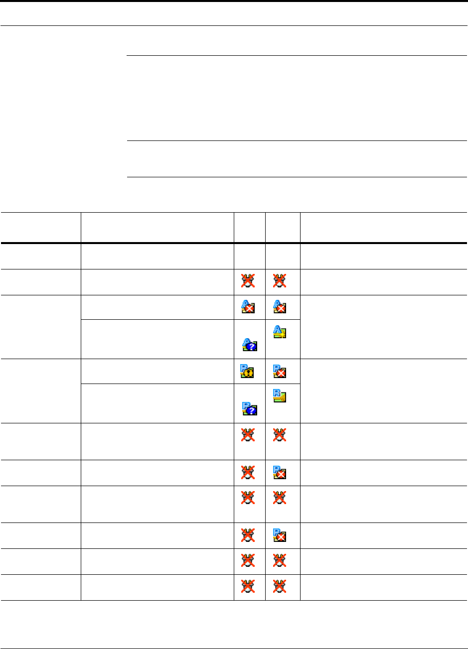
Help Hot Line (U.S. only): 1-800-530-9960 8-21
D-620605-0-20 Rev A CONFIDENTIAL
Troubleshooting CATV
8.4 Troubleshooting CATV
Refer to Table A-1 on page A-3 for a description of the CATV cable connectivity. The
following table summarizes CATV problems, as reported by AdminBrowser if a
cable is cut or miswired.
NOTE: Recommended minimum and maximum CATV cable lengths vary
depending upon the type of CATV cable used. Refer to the note on page 8-5.
Table 8-10 Summary of CATV Cable Wiring Problems
Type of
problem Message Icon IconaImpact
Wire 1 or 2 cut None High phase noise, degraded signal on both
Downlink and Uplink (high bit error rate)
Wire 3 or 6 cut • No communication with RAUn RAU unable to communicate with Hub,
degraded performance or RAU off-line
Wire 4 or 5 cut • Portn UL RF path loss is too high Increased ripple in the uplink path,
decreased UL gain, or no UL gain
• Portn UL RF path loss is higher than
recommended
Wire 7 or 8 cut • The DL RF path loss is too high Increased ripple in the downlink path,
RAU off-line
• The DL RF path loss is higher than
recommended
Wire 1 to RJ-45
pin 3 or 6
• No communication with RAUn RAU unable to communicate with Hub,
RAU’s RS-485 port damaged, degraded
performance or RAU off-line
Wire 1 to RJ-45
pin 4, 5, 7 or 8
•RAUn over current RAU will not power on.
Wire 2 to RJ-45
pin 3 or 6
• No communication with RAUnRAU unable to communicate with Hub,
RAU’s RS-485 port damaged, degraded
performance or RAU off-line
Wire 2 to RJ-45
pin 4, 5, 7 or 8
•RAUn over current RAU will not power on
Wire 3 to RJ-45
pin 4, 5, 7 or 8
• No communication with RAUnRAU unable to communicate with Hub,
degraded performance or RAU off-line
Wire 6 to RJ-45
pin 4, 5, 7 or 8
• No communication with RAUnRAU unable to communicate with Hub,
degraded performance or RAU off-line
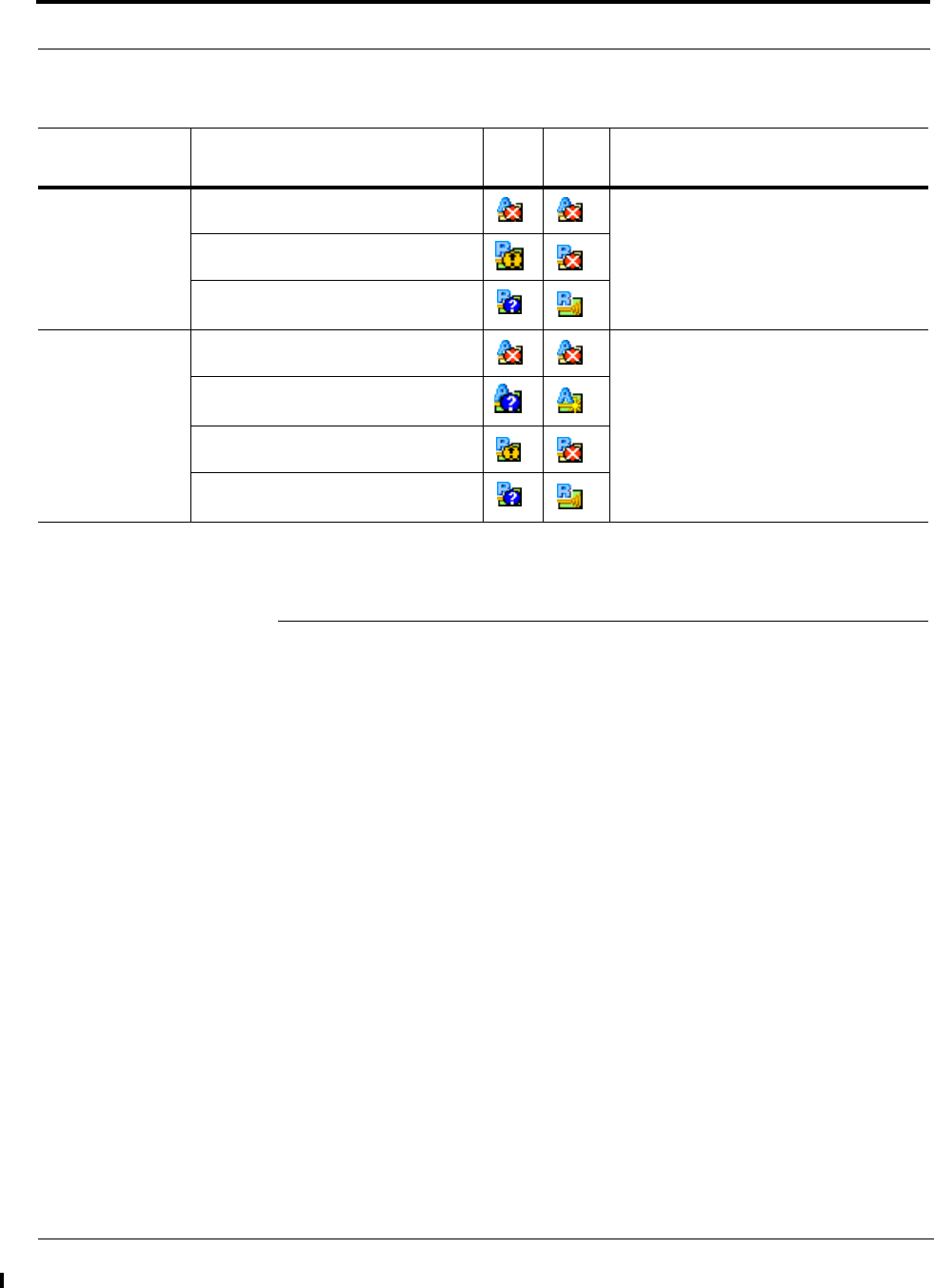
Technical Assistance
8-22 InterReach Fusion SS Installation, Operation, and Reference Manual
CONFIDENTIAL D-620605-0-20 Rev A
8.5 Technical Assistance
Call our help hot line for technical assistance:
1-800-530-9960 (U.S. only)
+1-408-952-2400 (International)
Leave your name and phone number and an LGC Wireless customer service repre-
sentative will return your call within an hour. Be prepared to provide the following
information when you receive the return call:
• Company name
• End user name
• Type of system, model number, frequency
• Approximate time in service (warranty), sales order number
• Description of problem
• LED status
• AdminBrowser faults, warnings, and status messages
Wire 4 to RJ-45
pin 7 or 8
•Portn UL RF path loss is too high Increased ripple in the downlink and
uplink path, degraded performance or
RAU off-line.
• The DL RF path loss is too high
• The DL RF path loss is higher than
recommended
Wire 5 to RJ-45
pin 7 or 8
•Portn UL RF path loss is too high Increased ripple in the downlink and
uplink path, degraded performance or
RAU off-line.
•Portn UL RF path loss is higher than
recommended
• The DL RF path loss is too high
• The DL RF path loss is higher than
recommended
a. Applies to earlier Firmware versions.
Table 8-10 Summary of CATV Cable Wiring Problems (continued)
Type of
problem Message Icon IconaImpact

InterReach Fusion SS Installation, Operation, and Reference Manual A-1
D-620605-0-20 Rev A CONFIDENTIAL
APPENDIX A Cables and Connectors
A.1 CATV Cable
• Connects the Fusion SingleStar Hub to the RAU(s)
• Transmits multiband (downlink) and receives (uplink) IF signals
• Delivers DC electrical power to the RAUs. The Fusion SingleStar Hub’s DC volt-
age output is 54V DC nominal. A current limiting circuit is used to protect the Hub
if it reaches its current limit
• Carries configuration and status information
• Use shielded F connectors
• Lengths:
RG-59:
• Minimum: 10 meters (33 ft.)
• Maximum: 150 meters (492 ft.)
RG-6:
• Minimum: 10 meters (33 ft.)
• Maximum: 200 meters (656 ft.)
RG-11:
• Minimum: 10 meters (33 ft.)
• Maximum: 300 meters (984 ft.)
NOTE: Recommended minimum and maximum CATV cable lengths vary
depending upon which CATV cable you use.
The nominal DC impedance of the CATV cable is 0.08 ohm/meter and the nominal
RF impedance is 100 ohm.

A-2 InterReach Fusion SS Installation, Operation, and Reference Manual
CONFIDENTIAL D-620605-0-20 Rev A
NOTE: Be sure to test cable termination before installing the cable.
NOTE: Commscope CATV cable or equivalent is required:
Commscope 20655V for RG-59.
Commscope 2279V for RG-6.
Commscope 2293K for RG-11.
NOTE: LGC Wireless requires solid copper center conductor CATV cable for
proper DC voltage to the RAU.
Use the following connectors and tools to prepare the ends:
Commscope cable part number: 2065V
Canare part number: F connector FP-C4F
Crimp Tool TC-1
Crimp Die TCD-4C
Cable Strip preparation tool TS100E
Commscope cable part number: 2279V
Canare part number: F connector FP-C55A
Crimp Tool TC-1
Crimp Die TCD-35CA
Cable Strip preparation tool TS100E
Commscope cable part number: 2293V
Canare part number: F connector FP-C71A
Crimp Tool TC-1
Crimp Die TCD-7CA
Cable Strip preparation tool TS100E
A.2 Coaxial Cable
• Connects a Fusion SingleStar Hub to a repeater, base station, or SmartSource APU
(N-type connectors)
• Connects an RAU to a passive antenna (N connectors)

Help Hot Line (U.S. only): 1-800-530-9960 A-3
D-620605-0-20 Rev A CONFIDENTIAL
A.3 Standard Modem Cable
This cable connects a modem to the Fusion SingleStar Hub’s front panel serial port.
A.4 RJ-45 100 BASE-T 100 Cross-over Cable
An RJ-45 100 BASE-T cross-over cable is used to connect a standard browser PC to
to the AdminBrowser with a Fusion SingleStar Hub. A cable is included with the
Fusion SingleStar Hub.
Table A-1 RJ-45 Cross-over Cable Pinout
From Signal To Signal
P1-4 DTR P2-6, P2-1 DSR, DCD
P1-6 DSR P1-1, P2-4 DCD, DTR
P1-3 TXD P2-2 RXD
P1-2 RXD P2-3 TXD
P1-5 GND P2-5 GND
P1-7 RTS P2-8 CTS
P1-8 CTS P2-7 RTS
P1-9 N/C N/C N/C

A-4 InterReach Fusion SS Installation, Operation, and Reference Manual
CONFIDENTIAL D-620605-0-20 Rev A

InterReach Fusion SS Installation, Operation, and Reference Manual B-1
D-620605-0-20 Rev A CONFIDENTIAL
APPENDIX B Compliance
B.1 Fusion SingleStar System Approval Status
InterReach Fusion SingleStar has been approved as shown below.
900 Paging/SMR
• Safety: UL 60950 3rd Edition
• EMC: FCC part 15 class A
• Radio: FCC Part 90
850 Cellular Products
• Safety: UL 60950 3rd Edition
• EMC: FCC part 15 class A
• Radio: FCC Part 22
1800 DCS Products
• Safety: CB scheme evaluation to IEC 950, 3rd Edition with all national deviations
• EMC: EN 301 489-8 V.1.1.1 (2000-09), CISPR 24: 1998
• Radio: ETS 300 609-4 V.8.0.2 (2000-10)
900 GSM/EGSM Products
• Safety: CB scheme evaluation to IEC 950, 3rd Edition with all national deviations
• Radio: EN 301 502 V.7.0.1 (2000-08)
• EMC: EN 301 489-8 V.1.1.1 (2000-09), CISPR 24: 1998

B-2 InterReach Fusion SS Installation, Operation, and Reference Manual
CONFIDENTIAL D-620605-0-20 Rev A
800 iDEN Products
• Safety: UL 60950, 3rd Edition
• EMC: FCC part 15 class A
• Radio: FCC part 90
1900 PCS Products
• Safety: UL 60950 3rd Edition
• EMC: FCC part 15 class A
• Radio: FCC part 24
2100 UMTS Products
• Safety: CB scheme evaluation to IEC 950, 3rd Edition with all national deviations
• EMC: ETSI TS 125 113 125 113: V4.3.0 (2002-09)
• Radio: ETSI TS 125 143 125 143: V5.2.0 (2002-09)
NOTE: for Canadian customers, the Manufacturer’s rated output power1 of
this equipment is for single carrier operation. For situations when multiple
carrier signals are present, the rating would have to be reduced by 3.5 dB,
especially where the output signal is re-radiated and can cause interference
to adjacent band users. This power reduction is to be by means of input
power or gain reduction and not by an attenuator at the output of the device.
NOTE: This device complies with Part 15 of the FCC Rules. Operation is
subject to the following two conditions: (1) this device may not cause harm-
ful interference, and (2) this device must accept any interference received,
including interference that may cause undesired operation.
1. “Manufacturer’s rated output power” refers to Fusion’s downlink P1dB. The power per carrier tables take into account this
power reduction for multiple carriers.

Help Hot Line (U.S. only): 1-800-530-9960 B-3
D-620605-0-20 Rev A CONFIDENTIAL
B.2 Human Exposure to RF
The U.S. Federal Communications Commission (FCC) has adopted limits of human
exposure to radio frequency (RF) emissions from portable or fixed RF systems that
are regulated by the FCC. The exposure limits on the incident electric and magnetic
fields and power densities are based on ANSI/IEEE and NCRP RF Safety Guidelines.
The limits are also prescribed in terms of the mass-normalized rates of internal energy
absorption by tissues (specific absorption rates or SARs) which should not exceed
0.08 W/kg as averaged over the whole body and 1.6 W/kg for any 1-g of tissue.
Similarly, the U.K. National Radiological Protection Board (NRPB) and the Interna-
tional Commission on Non-Ionizing Radiation Protection (ICNIRP) have both estab-
lished guidelines for maximum RF exposure levels that are likely to not pose health
risks. For the general public, ICNIRP recommends maximum exposure levels of
2.0 W/kg for any 10-g of tissue. This recommendation is 5 times lower than that of
NRPB.
The specific absorption rate (SAR) was measured for a radiated power of 20 dBm
(100 mW) which is the maximum radiated for both of the antennas. The highest SAR
regions for each of the antennas for separation distances of 0, 1, 2, and 3 cm to the tis-
sue-simulant model were determined in the first instance by using a coarser sampling
with a step size of 8.0 mm over three overlapping scan areas for a total scan area of
8.0 × 9.6 cm. After identifying the regions of the highest SAR for each of the cases,
the SAR distributions were measured with a resolution of 2 mm in order to obtain the
peak 1 cm 3 or 1-g SAR.
Antenna gain is restricted to 1.5 W ERP (2.49 W EIRP) in order to satisfy RF expo-
sure compliance requirements. If higher than 1.5 W ERP, routine MPE evaluation is
needed. The antennas should be installed to provide at least 20 cm from all persons to
satisfy MPE requirements of FCC Part 2, 2.1091.

B-4 InterReach Fusion SS Installation, Operation, and Reference Manual
CONFIDENTIAL D-620605-0-20 Rev A
This page is intentionally left blank.