ADC Telecommunications FWM0801A GSM Base Station User Manual Manual 1
ADC Telecommunications Inc GSM Base Station Manual 1
UserManual.wiki
>
ADC Telecommunications
>
FWM0801A User Manual
>
Manual 1
Contents
1.
Manual 1
2.
Manual 2
Manual 1
Navigation menu
Upload a User Manual
Namespaces
Wiki Guide
HTML
PDF
Info
Views
User Manual
Discussion / Help
Navigation
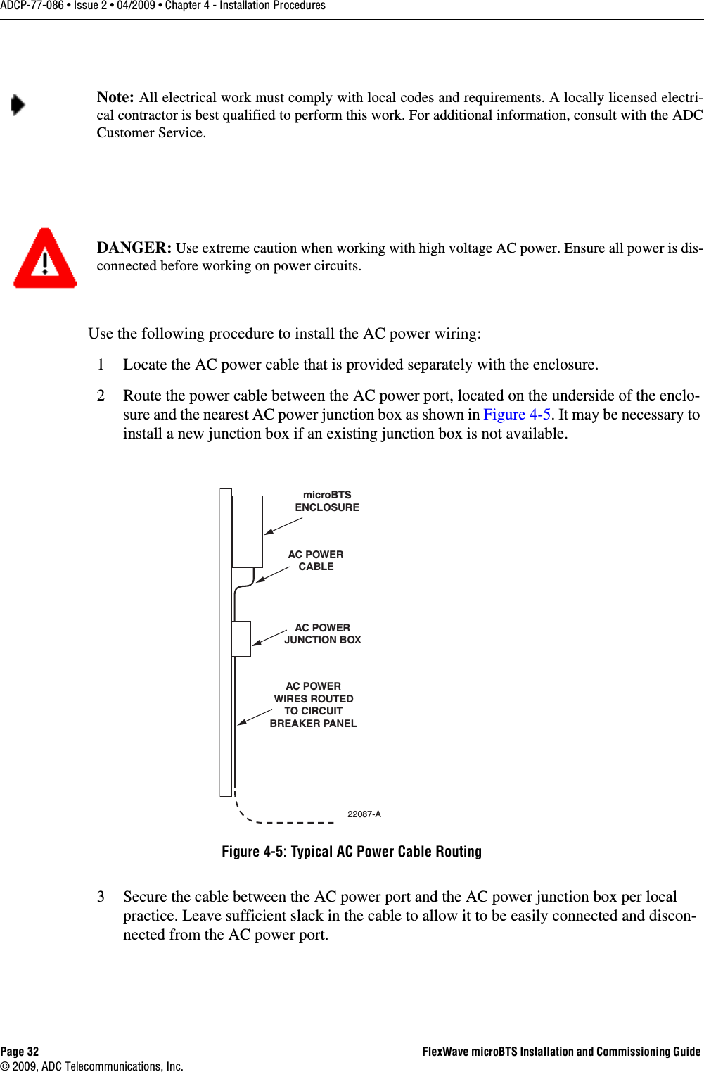
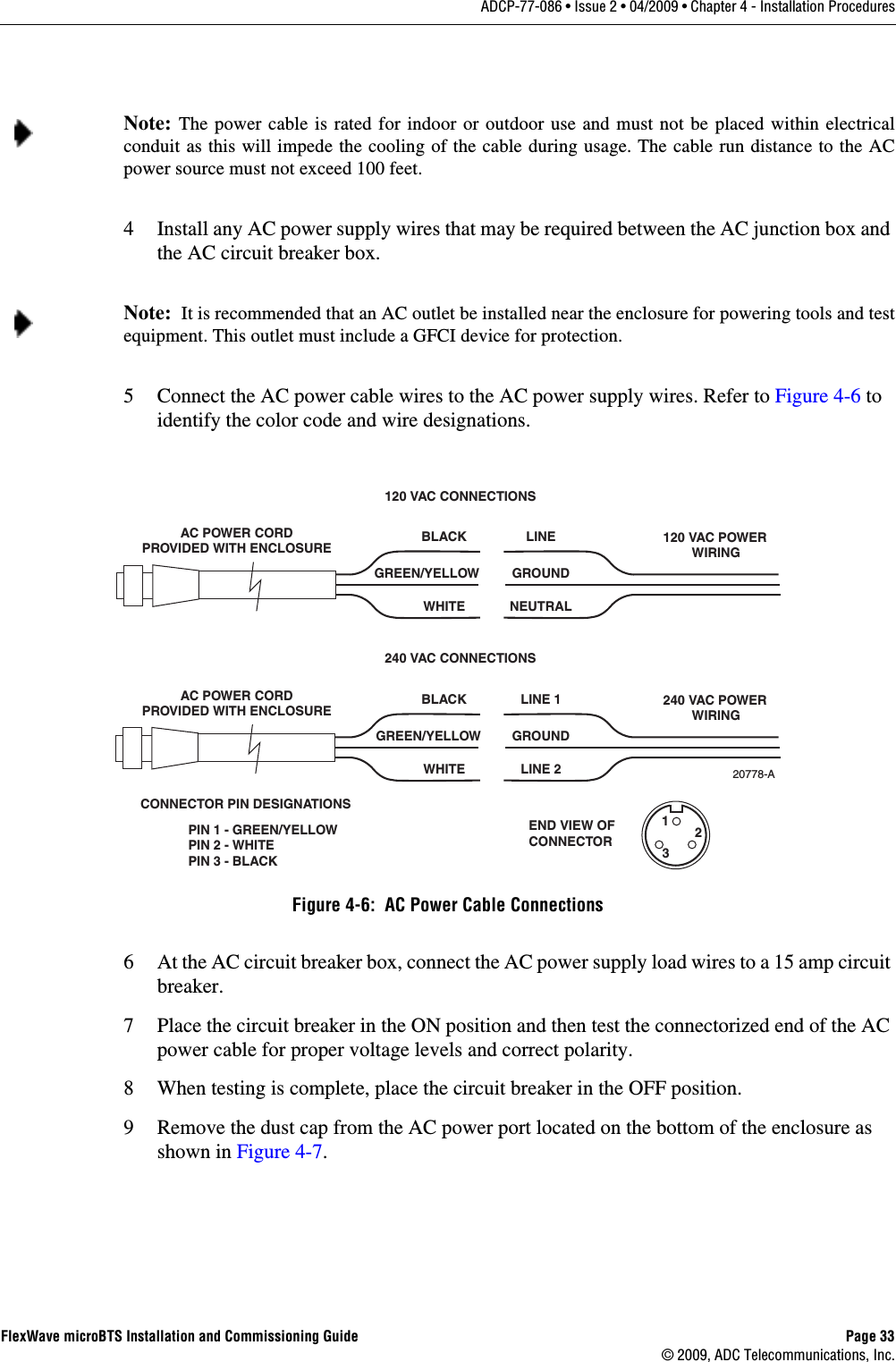
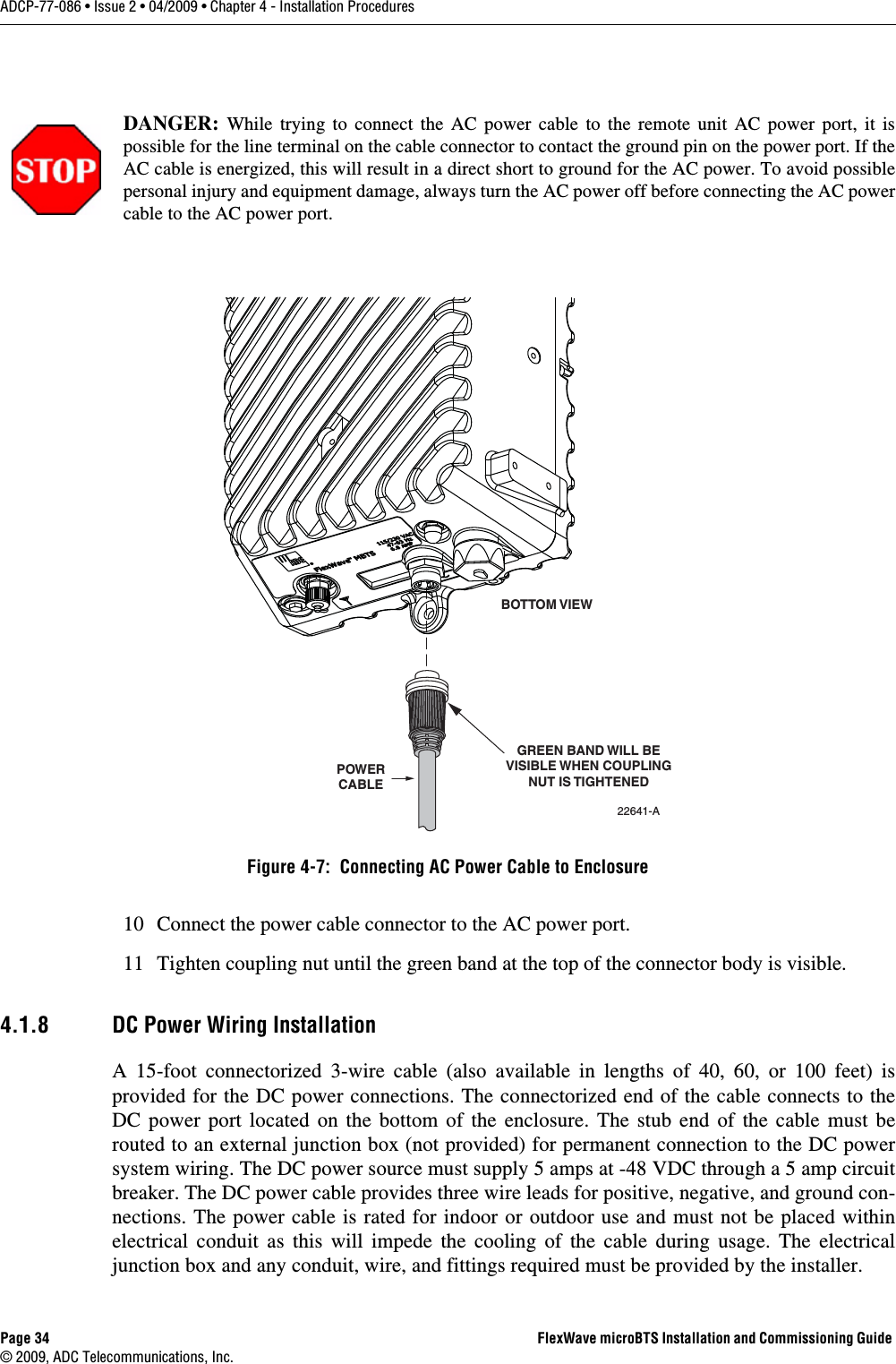
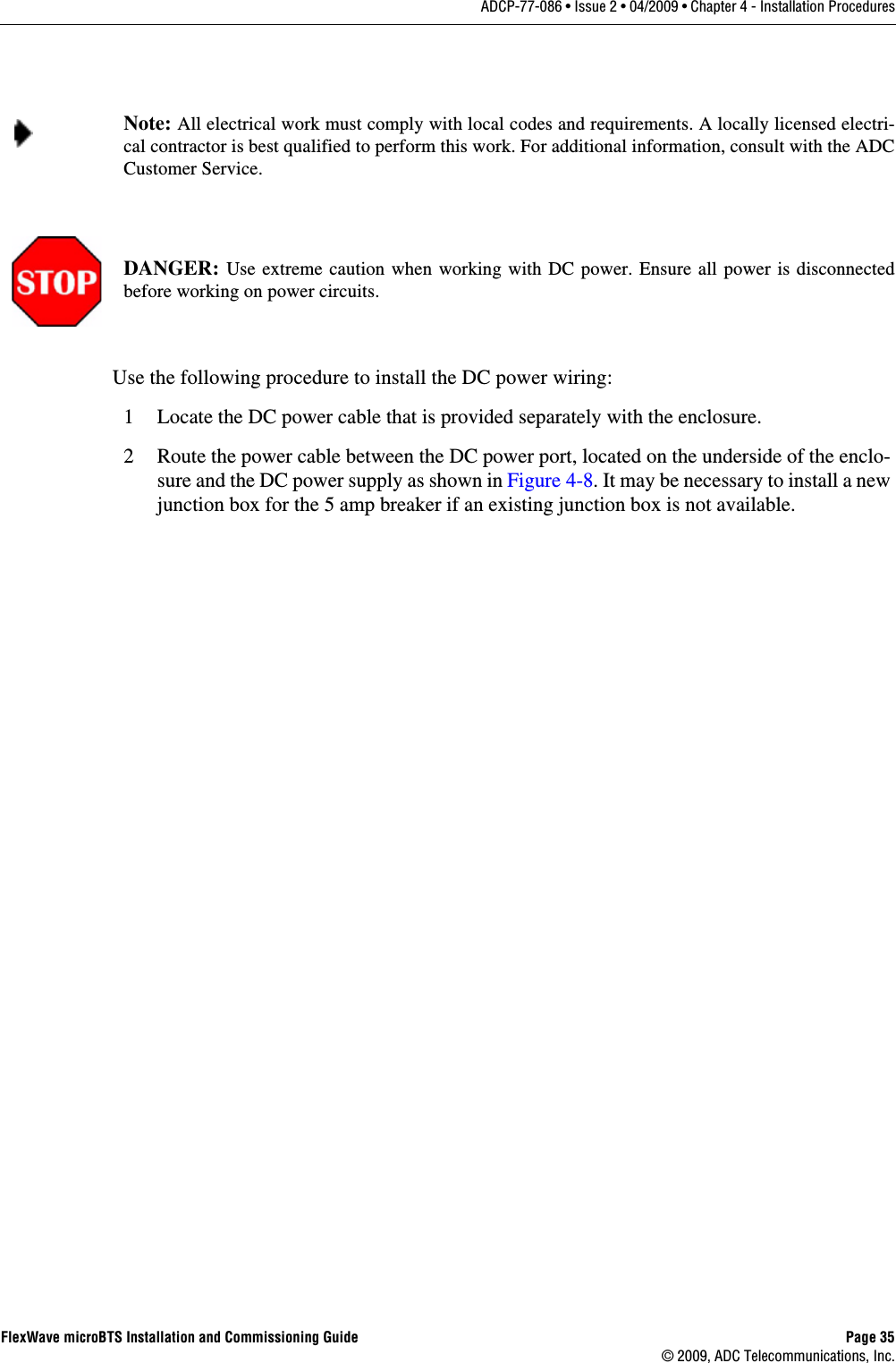
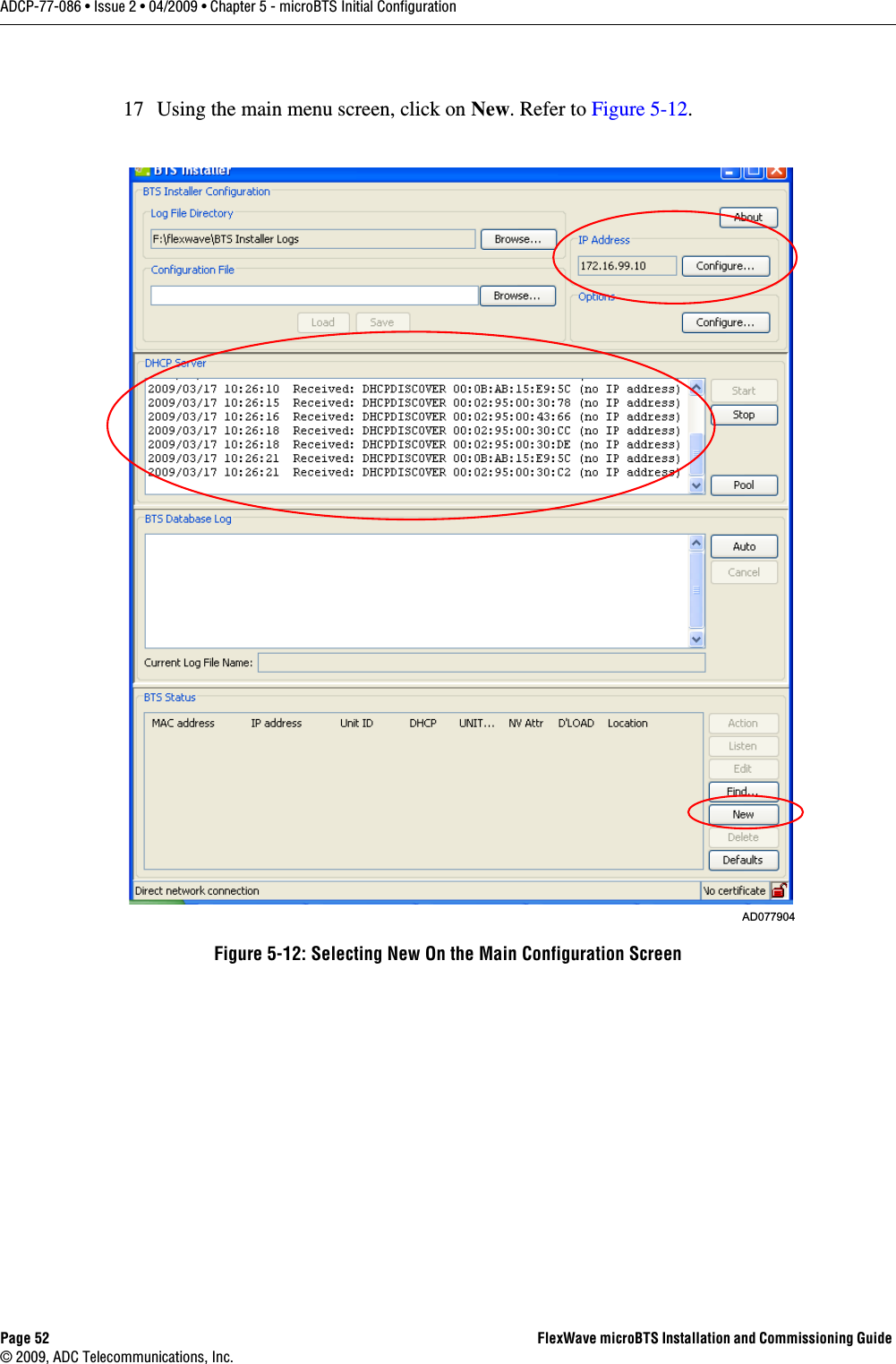
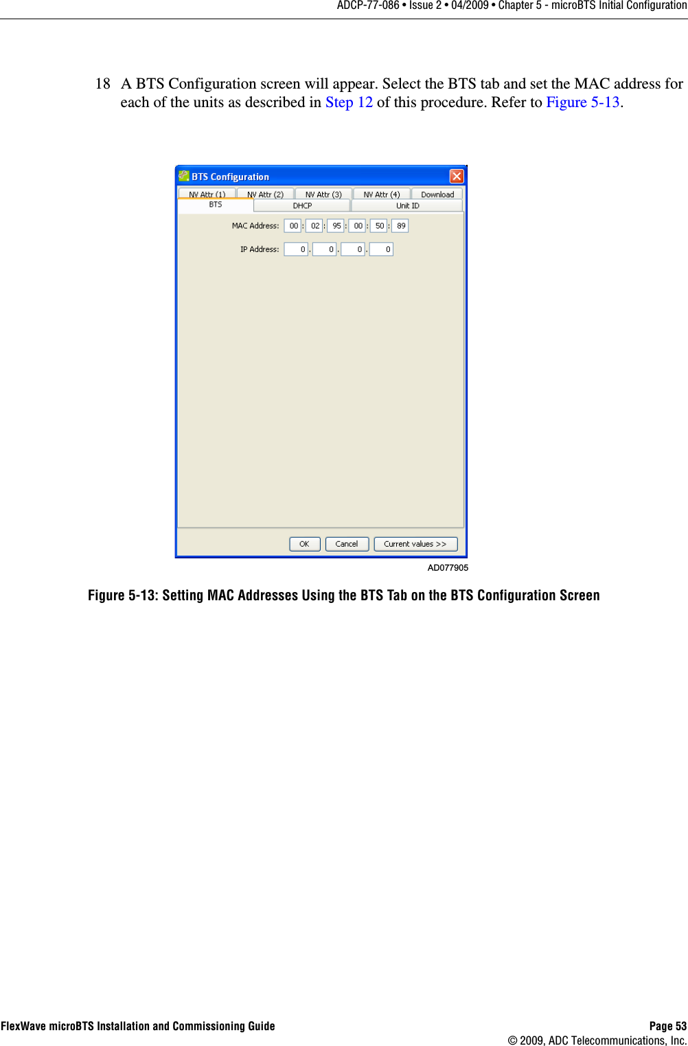
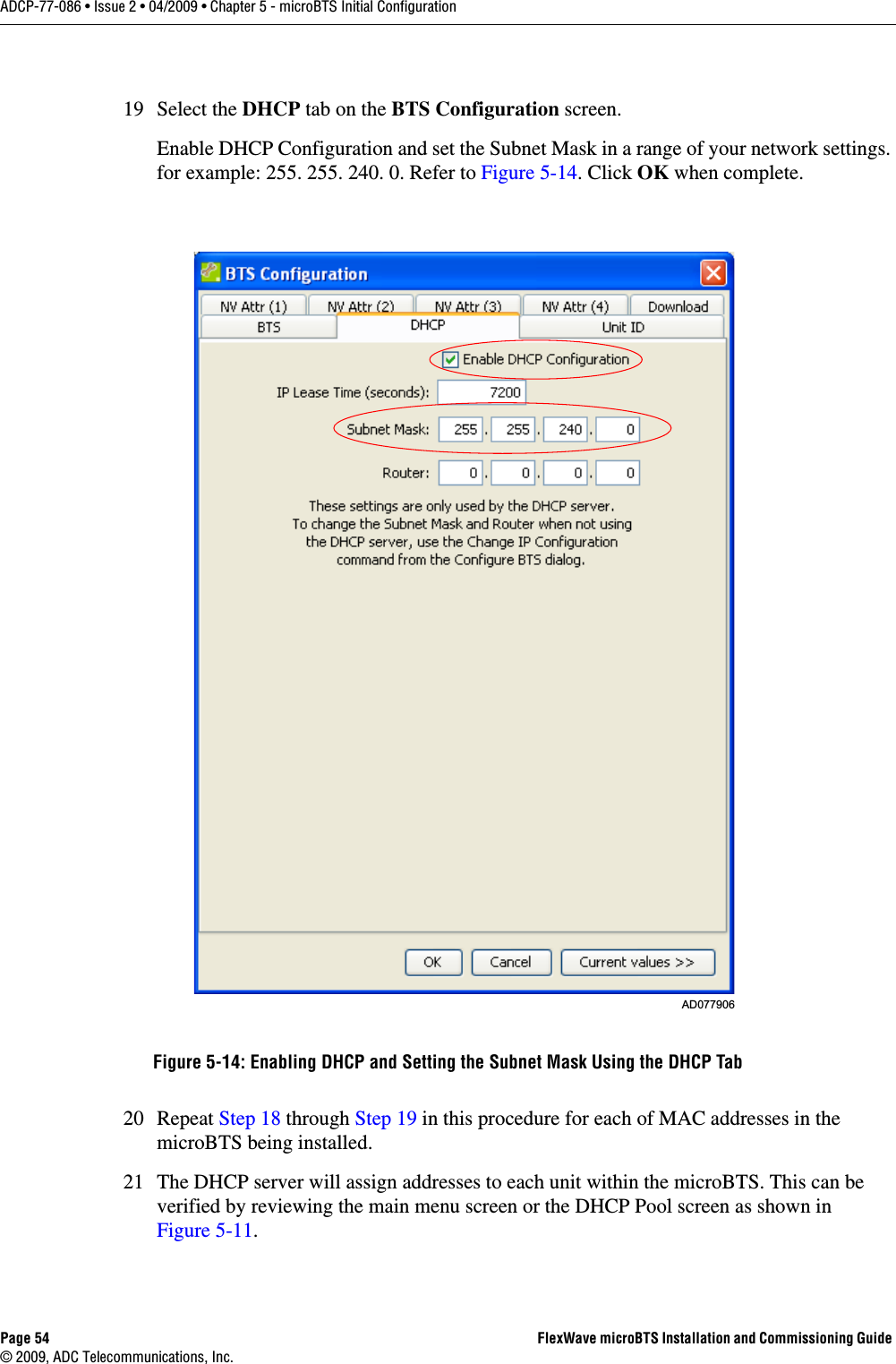
![Page x FlexWave microBTS Installation and Commissioning Guide © 2009, ADC Telecommunications, Inc.ADCP-77-086 • Issue 2 • 04/2009 • PrefaceConventions Used in This Manual Convention MeaningBody Text Used for regular body textBold Indicates a menu or button choiceCommand Indicates computer generated text and promptsUser Input Indicates user input<hostname> In command syntax, indicates user-specified command line parameters<variable> In body text, indicates user-specified command line parameters[BRACKETS] Indicates a key on the keyboard or instrumentNote: Provides relevant additional information](https://usermanual.wiki/ADC-Telecommunications/FWM0801A.Manual-1/User-Guide-1127081-Page-12.png)