ADC Telecommunications FWM1901A FlexWave™ microBTS User Manual 01
ADC Telecommunications Inc FlexWave™ microBTS 01
Contents
- 1. User manual 01
- 2. User manual 02
- 3. User manual 03
- 4. User manual 04
User manual 01
© ip.access Ltd Page 1 of 12
COMPANY CONFIDENTIAL CENG0210_XB Hardware Installation -
nanoBTS.doc
1.1 Introduction
1.1.1 Purpose and Scope
This documents the procedure used to install the nanoBTS hardware and physical
connections together with applying the base software configuration.
1.1.2 Related Documents
Reference
Number Document Title Description
1 CENG0133 Customer Safety and Regulatory Information
2 CENG0220 Operations Procedure
1.2 Warnings
This document must be translated into your local language, if English is
not commonplace.
This system is designed to be operated indoors as a fixed system
device and must be located either on or near the ceiling away from the
user. It must be mounted in a manner to ensure that all users and
bystanders and users are kept a minimum of 20cm away from
antennas at all times.
Do not touch or move the antenna(s) while the unit is transmitting or
receiving. Do not hold any component containing a radio such that the
antenna is very close to or touching any exposed parts of the body,
especially the face or eyes while transmitting.
In most parts of the world, regulatory approval(s) are needed before
the nanoBTS is operated.
Do not connect any device other than the nanoBTS to any RJ45 socket
that has been enabled for nanoBTS connection (i.e. 48Vdc operation).
© ip.access Ltd Page 2 of 12
COMPANY CONFIDENTIAL CENG0210_XB Hardware Installation -
nanoBTS.doc
The nanoBTS is intended for dry indoor applications only. If evidence
of condensation is present do not apply power to the nanoBTS.
The cabling to the nanoBTS and power supply is to run indoors only.
The nanoBTS must only be powered using a PSU supplied by
ip.access; the approved part is APC model PSU109 with UL file
number E231617.
PSUs supplied by ip.access must not be used for powering any other
equipment.
The external antenna ports are not covered by this products UL
approval.
1.3 Regulatory Information
For all regulatory information please see CENG0133 Ref{1}.
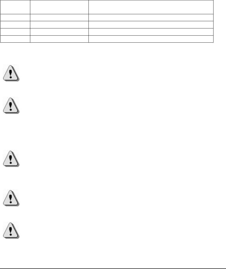
1.4 Unpacking
Unpack nanoBTS and check to see that the unit has not been damaged in transit. Any
damaged units should be returned to your supplier.
Figure 1 - Unpacking the nanoBTS
© ip.access Ltd Page 3 of 12
COMPANY CONFIDENTIAL CENG0210_XB Hardware Installation -
nanoBTS.doc
1.5 Fitting the External Antenna Kit (optional)
NOTE: When looking at the nanoBTS with the connections facing down and the LED
visible the antenna on the left is the Transmit antenna and the antenna on the right
hand side is the Receive antenna.
NOTE: The RF feeder cable must not be bent as this may result in a degraded
performance.
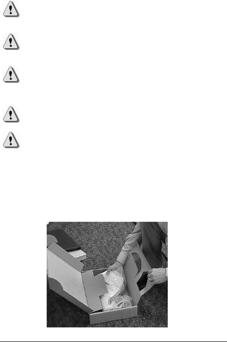
Remove the plastic covers by removing the top and bottom plates from both ends of
the nanoBTS. Lever gently apart with screwdriver in notch.
Antenna Cover
Top
Antenna Cover
Bottom
Notch to aid
removal of
cover
Antenna Cover
Body
Figure 2 - Removal of antenna covers
Remove the antenna cover body, by unscrewing the two Torx T20 screws retaining
Remove Torx Screws
Figure 3 - Removal of antenna cover body
© ip.access Ltd Page 4 of 12
COMPANY CONFIDENTIAL CENG0210_XB Hardware Installation -
nanoBTS.doc
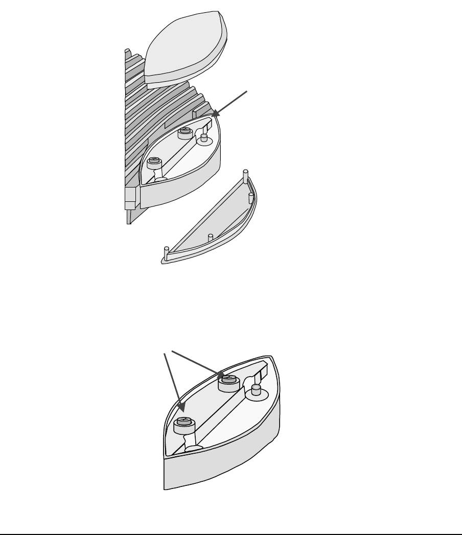
Fit the replacement antenna cover body ensuring that the feeder cable connector fits
into the antenna. Note that one cover only fits the receiver whilst the other fits the
transmitter.
Fit the clamp as shown below and second Torx screw, then replace top and bottom
covers.
Clamp plate
Figure 4 - Fit clamp plate
Repeat the process for the other end of nanoBTS
© ip.access Ltd Page 5 of 12
COMPANY CONFIDENTIAL CENG0210_XB Hardware Installation -
nanoBTS.doc
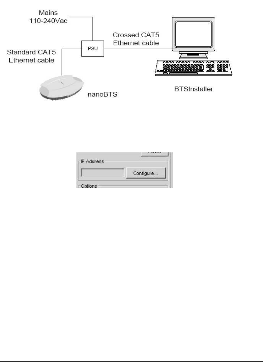
1.6 IP Configuration
• Connect the nanoBTS up as shown in Figure 5 nanoBTS Connections and
power on the nanoBTS
Figure 5 - Local BTS Connection
• Start the BTSInstaller application
• If the IP address of you PC is not shown the IP Address window (see Figure 6)
Figure 6 - BTSInstaller Interface
• Click on the “Configure” button and select the network interface, then IP
address that is being used to connect to the nanoBTS then click on the “OK”
button.
• In the DHCP pane, click on the “Pool“ button and then the “Add” button
• Enter the IP address for the nanoBTS and click on the “OK” button.
• In the DHCP pane, click on the “Stop” and then “Start” button, to make the
DHCP server take the new IP address pool.
• Under the BTS Status pane, click on the “New” button
• From the “BTS tab”, enter the MAC address of the nanoBTS (see label on the
side of the nanoBTS
• From the “DHCP tab”, Enable the “DHCP Configuration” tick box and enter
the Subnet Mask and Router address. If no router is used leave the router
address as 0.0.0.0
• From the “Unit ID” tab, Enable the “Configure Unit ID” tick box and enter the
Site ID. If the nanoBTS is part of a multi-TRX site also enter the TRX ID.
• From the ”NV Attr (1)” tab, enable the “NV Attr Configuration” tick box and
select the “Configure Flags” tick box and set “F1”, “F2” and ”F3” to the “ON”
state.
© ip.access Ltd Page 6 of 12
COMPANY CONFIDENTIAL CENG0210_XB Hardware Installation -
nanoBTS.doc
• From the “NV Attr (2)” tab, enable the “Configure Primary OML” tick box
and set the “Primary OML IP Address” to the IP address of the BSC.
• From the “NV Attr (2)” tab, enable the “Configure Location” tick box and
enter a text string for the nanoBTS location.
• From the “NV Attr (2)” tab, enable the “Configure Unit Name” tick box and
enter a text string for the nanoBTS name.
• If new software is required to be downloaded to the nanoBTS, then from the
“Download” tab; enable the “Software Download” tick box.
• Click on the “Browse” button and using the standard Windows dialogue box,
select the software you wish to download to the nanoBTS and then click on
the “OK” button.
• Click on the “OK” button to accept the configuration.
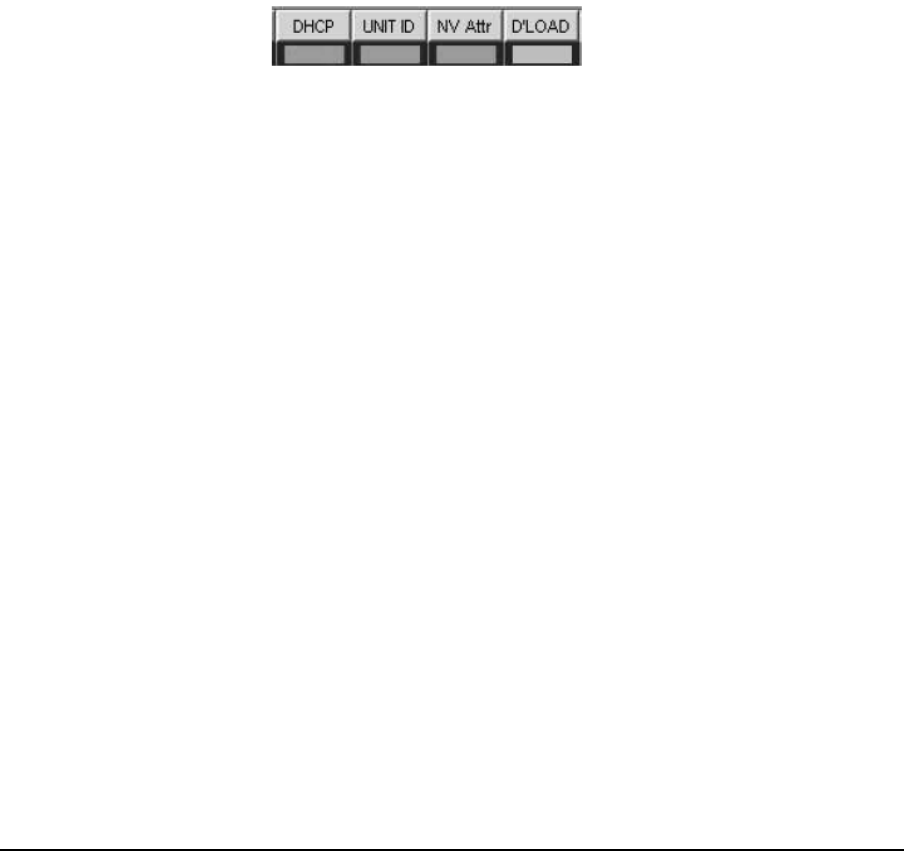
• From the “BTS Database Log” window, click on the “Auto” button.
The BTSInstaller application will now assign an IP address and automatically
configure the nanoBTS parameters. Once this process has completed, the four (4)
indicators in the “BTS Status” pane will turn green.
Figure 7 - BTS Status
© ip.access Ltd Page 7 of 12
COMPANY CONFIDENTIAL CENG0210_XB Hardware Installation -
nanoBTS.doc
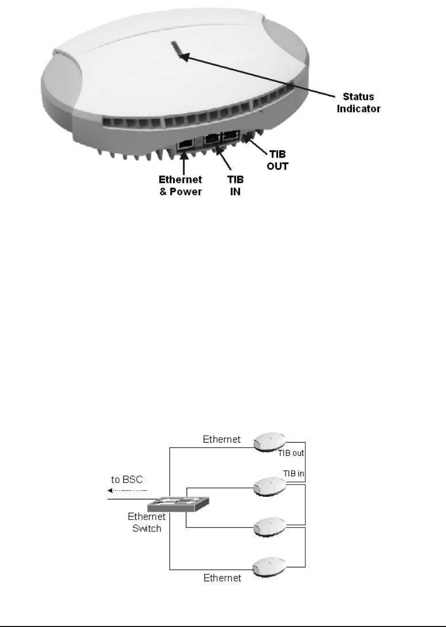
1.7 Cabling the nanoBTS
Figure 8 - nanoBTS Connections
1.7.1 Ethernet
Each nanoBTS must be connected to an Ethernet switch or hub via either a 109
ip.access single power inserter or 126 ip.access Powered Ethernet Switch. Refer to
CENG0033 for details of the power supply connections.
1.7.2 Timing Interface Bus (TIB) – Multi-TRX only
The Timing Interface Bus (TIB) is used to provide clock and signaling between the
nanoBTS when operating in a Multi-TRX configuration.
The TIB OUT from the Master TRX must be connected to the TIB IN of the slave
TRX. This in turn has its TIB OUT connected to the next TRX in the chain. See
Figure 9 - TIB Connections
Figure 9 - TIB Connections
© ip.access Ltd Page 8 of 12
COMPANY CONFIDENTIAL CENG0210_XB Hardware Installation -
nanoBTS.doc
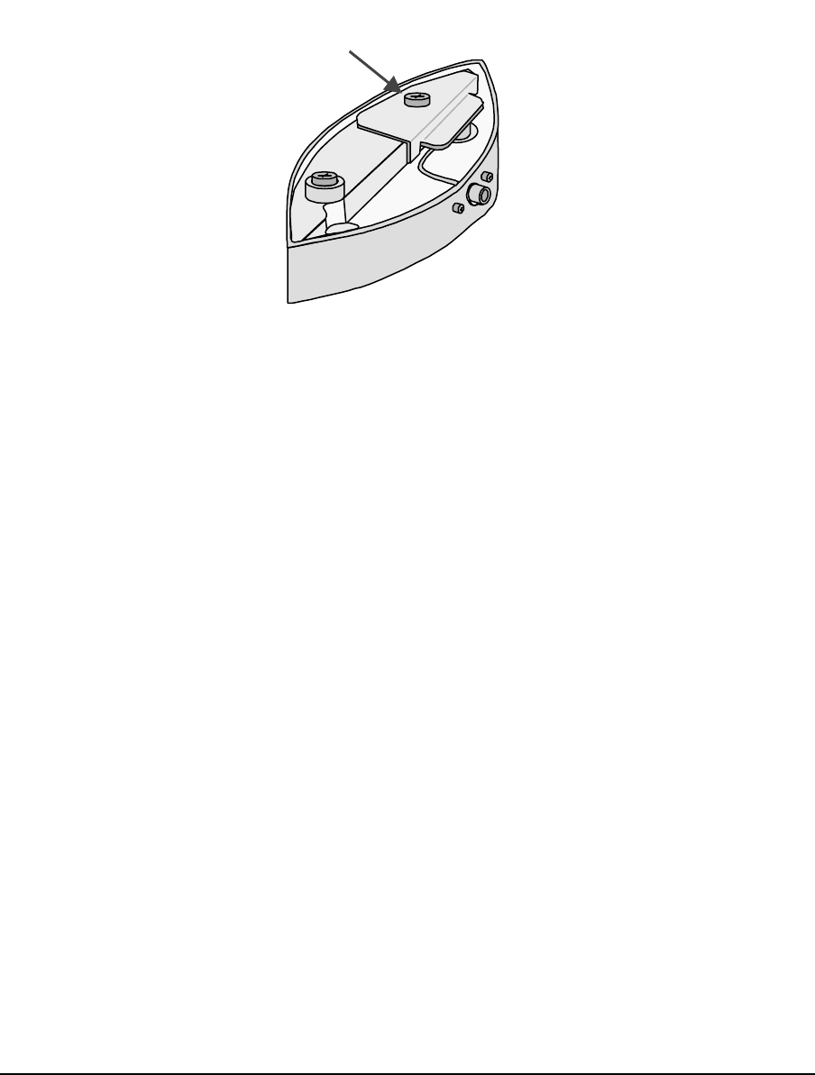
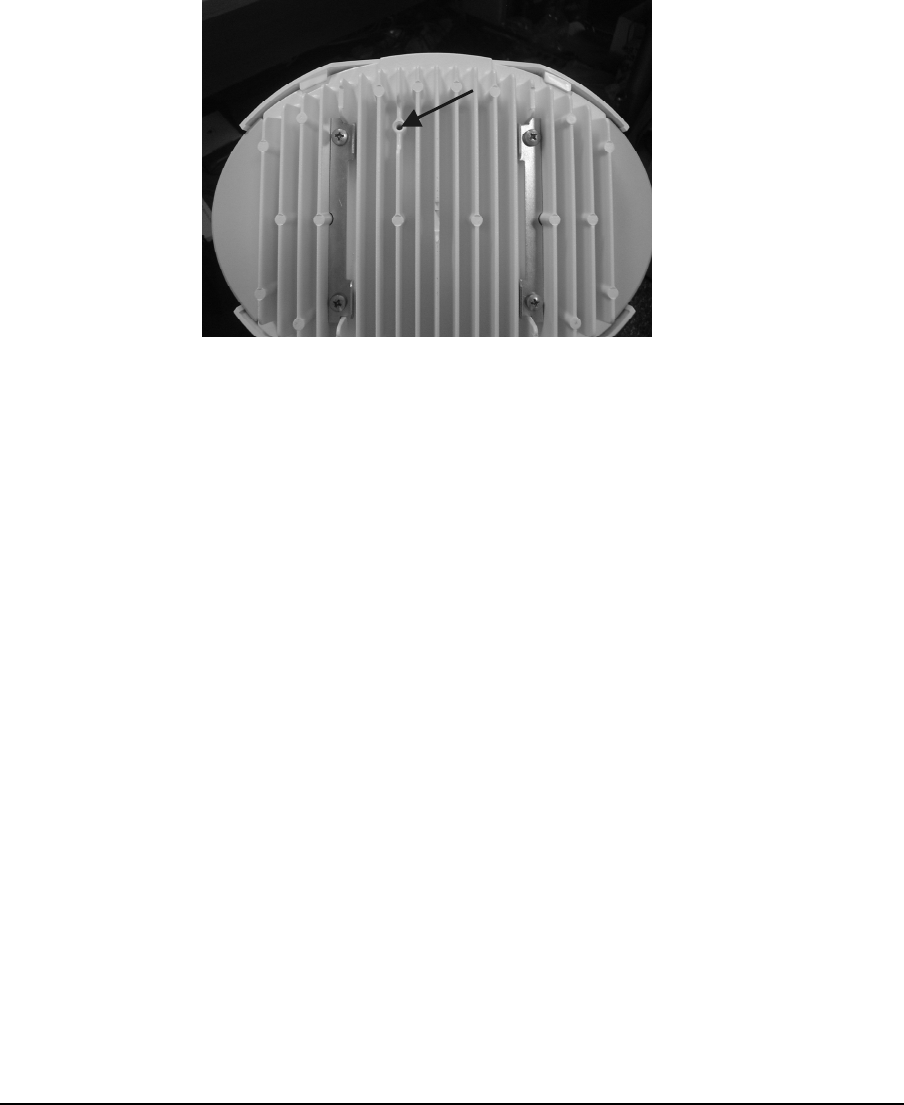
1.7.3 Earth Strap – Multi-TRX only
When the nanoBTS is operated in a Multi-TRX configuration, each of the nanoBTS
must be connected together using the supplied earth kit.
To fit the earth strap, remove the nanoBTS from the mounting plate
Using the screw provided, screw the Earth Strap to the stud on the rear of the
nanoBTS, see Figure 10 - Earth Stud.
Earth
Stud
Figure 10 - Earth Stud
Connect the other end of the Earth lead to the next nanoBTS Earth stud in the chain.
© ip.access Ltd Page 9 of 12
COMPANY CONFIDENTIAL CENG0210_XB Hardware Installation -
nanoBTS.doc
1.8 Mounting the nanoBTS
The location of each nanoBTS is shown on the installation floor plan produced at the
network planning stage. The network wiring must be complete before the nanoBTS
can be installed and commissioned. The nanoBTS should be placed on a wall at or
above head height or on a ceiling.
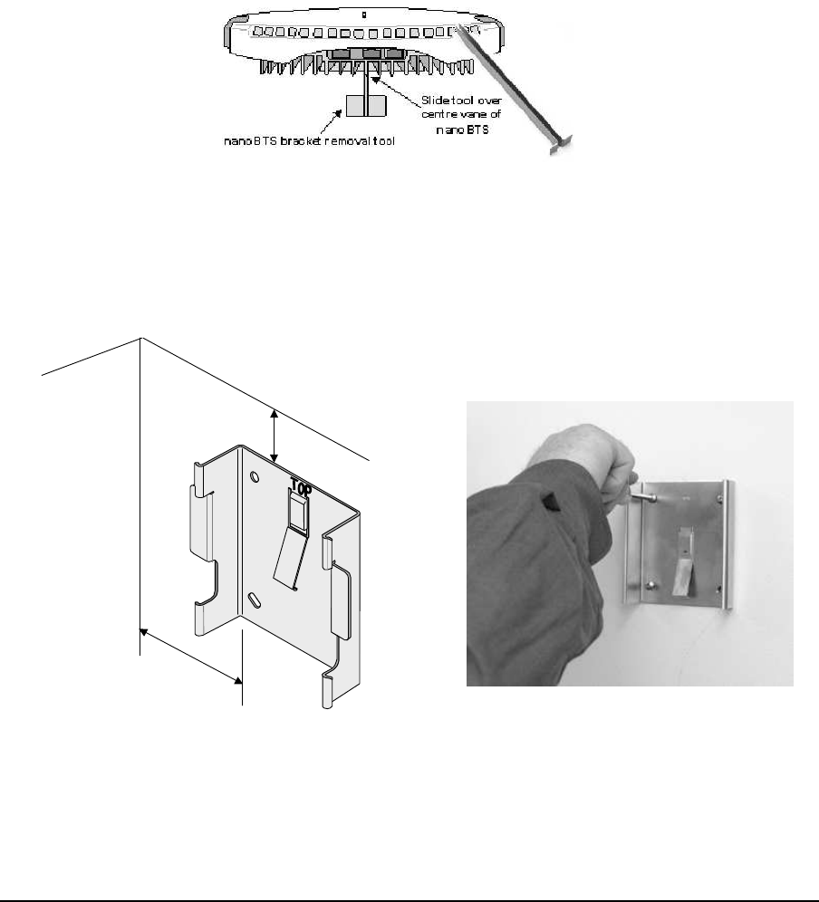
Remove the nanoBTS from the bracket by sliding the removal tool over the central fin
between the bracket and the body of the unit to disengage the locking spring, slide
bracket to separate it from the main body of the unit. The tool may be inserted from
the top or bottom of the nanoBTS
Figure 11 - nanoBTS Bracket Removal
Position the bracket on the wall and mark the position of the four screw holes. The top
of the bracket MUST be positioned uppermost. Ensure that the bracket is level and
sufficient clearance is maintained to allow the unit to be located on the bracket (at
least 80mm from the bracket to the top of wall and 120mm from the side of the
bracket to a side wall). See the diagram below, Figure 12 - Fixing the wall bracket.
80mm min
120mm min
Figure 12 - Fixing the wall bracket
Drill the four holes in the positions marked previously and insert wall plugs (if
required) and fix the mounting bracket securely to the wall. The bracket is designed to
allow the nanoBTS unit to be mounted with the connections at the bottom of the unit.
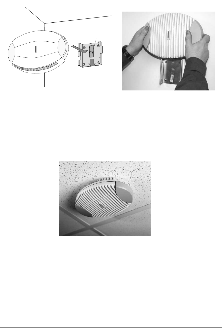
Slide the nanoBTS onto the bracket and ensure that the retaining spring engages into
the indent at the rear of the unit.
© ip.access Ltd Page 10 of 12
COMPANY CONFIDENTIAL CENG0210_XB Hardware Installation -
nanoBTS.doc
2
Locking Spring
1
TOP
Figure 13 - Mounting the nanoBTS
When fixing to a ceiling or a sloping wall the same fixing process and clearances
should be observed as for fixing to a wall (at least 80mm from the bracket to the top
of wall and 120mm from the side of the bracket to a side wall). On a sloping surface
the top of the bracket MUST be uppermost. Once the unit has been attached to the
bracket the outer cover MUST be removed to expose the cooling vanes, as shown in
Figure 14 - Ceiling Mounted nanoBTS
Figure 14 - Ceiling Mounted nanoBTS
1.8.1 Mounting Multi-TRX nanoBTS
When the nanoBTS are to be installed in a Multi-TRX configuration, then each TRX
should be installed in a similar orientation but not closer than 30cm to each other.
A further specific constraint is that the TIB cables must be <1.5m and a 1.5mm2 Earth
cable must also be connected between each TRX with a length not exceeding that of
the TIB cable.

© ip.access Ltd Page 11 of 12
COMPANY CONFIDENTIAL CENG0210_XB Hardware Installation -
nanoBTS.doc
1.9 Initial Frequency Calibration
NOTE: The nanoBTS must be powered on for a minimum of 24 hours prior to final
frequency calibration. It is recommended that during installation an initial, local
calibration is made following a powered on time of > 10 minutes followed by a final
operational calibration after 24 hours power on time.
NOTE: If the nanoBTS is used in a Multi-TRX configuration, then the TIB OUT
must be disconnected from each nanoBTS in the chain prior to calibration and
reconnected afterwards.
• Using BTSInstaller, select the nanoBTS that is to be calibrated and then click
on the “Listen” button in the “BTS Status” pane.
• Select the frequency band to match that of the nanoBTS to be installed.
• Click on the “Connect” button, this will cause the nanoBTS TRX to power up.
The status LED will flash green when completed.
• Click on the “Channel Usage” tab and then click on the “Start Test” button.
• When completed click on the “BCCH Channel Usage” tab and then click on
the “Start Test” button.
• When completed, click on the “Frequency Synchronisation” tab.
• Select “Configure Test”
• Select the “Freq Sync Options” tab and then click on the “Apply Frequency
Synch Options” and change the Option to “Adjust The Clock To Correct The
Reported Errors” then click “OK”
• Click on the “Start Test” button.
Once the test completes then the calibration is completed and the procedure should be
repeated for all installed nanoBTS before reconnecting the TIB cables.
Following the 24-hour period, the Frequency Calibration procedure should be
performed as per the Operations procedure – Ref {2}

© ip.access Ltd Page 12 of 12
COMPANY CONFIDENTIAL CENG0210_XB Hardware Installation -
nanoBTS.doc
1.10 LED Status Indicators
The following table shows the meaning of the state LED under normal and fault
conditions.
State Pattern When Precedence
LED_SELF_TEST_FAILURE Red
Steady In boot or application code when a
power on self-test fails. 1 (High)
LED_UNSPECIFIED_FAILURE Red
Steady On s/w fatal errors. 2
LED_NO_ETHERNET Orange
Slow Flash Ethernet disconnected. 3
LED_FACTORY_RESET Red
Fast Blink Dongle detected at start up and the
factory defaults have been applied. 4
LED_NOT_CONFIGURED Alternating
Red/Green
Fast Flash
The unit has not been configured. 5
LED_DOWNLOADING_CODE Orange
Fast Flash Code download procedure is in
progress. 6
LED_ESTABLISHING_XML Orange
Slow Blink A management link has not yet been
established but is needed for the
TRX to become operational.
Specifically: for a master a Primary
OML or Secondary OML is not yet
established; for a slave an IML to its
master or a Secondary OML is not
yet established.
7
LED_SELF_TEST Orange
Steady From power on until end of
backhaul power on self-test 8
LED_NWL_TEST Green
Fast Flash OML established, NWL test in
progress 9
LED_OCXO_CALIBRATION Alternating
Green/Orange
Slow Blink
The unit is in the fast calibrating
state [SYNC]. 10
LED_NOT_TRANSMITTING Green
Slow Flash The radio carrier is not being
transmitted. 11
LED_OPERATIONAL Green
Steady Default condition if none of the
above apply. 12 (Low)