ADC Telecommunications FWM1901B FlexWave™ microBTS 1900 MHz 2X1 User Manual 75246

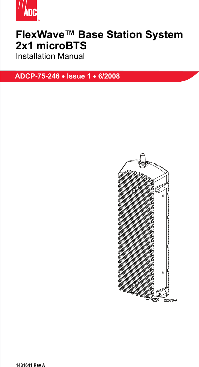
ADC Telecommunications Inc FlexWave™ microBTS 1900 MHz 2X1 75246

User manual

FlexWave™ Base Station System2x1 microBTSInstallation ManualADCP-75-246 • Issue 1 • 6/20081431641 Rev A22576-A
ADCP-75-246 • Issue 1 • 6/2008 • PrefacePage iiCOPYRIGHT© 2008, ADC Telecommunications, Inc. All Rights ReservedREVISION HISTORYLIST OF CHANGESThe technical changes incorporated into this issue are listed below.TRADEMARK INFORMATIONADC and ADC Telecommunications are registered trademarks of ADC Telecommunications, Inc. FlexWave is a trademark of ADC Telecommunications, Inc.nanoBTS is a trademark of ip.access Ltd.TORX is a trademark of Textron, Inc.DISCLAIMER OF LIABILITYContents herein are current as of the date of publication. ADC reserves the right to change the contents without prior notice. In no event shall ADC be liable for any damages resulting from loss of data, loss of use, or loss of profits and ADC further disclaims any and all liability for indirect, incidental, special, consequential or other similar damages. This disclaimer of liability applies to all products, publications and services during and after the warranty period.This publication may be verified at any time by contacting ADC’s Technical Assistance Center at 1-800-366-3891, extension 73475 (in U.S.A. or Canada) or 952-917-3475 (outside U.S.A. and Canada), or by e-mail to connectivity_tac@adc.com.ISSUE DATE REASON FOR CHANGE1 06/2008 Original releasePAGE IDENTIFIER DESCRIPTION OF CHANGE- Original releaseADC Telecommunications, Inc.P.O. Box 1101, Minneapolis, Minnesota 55440-1101In U.S.A. and Canada: 1-800-366-3891Outside U.S.A. and Canada: (952) 938-8080Fax: (952) 917-1717
ADCP-75-246 • Issue 1 • 6/2008 • PrefacePage iii© 2008, ADC Telecommunications, Inc.TABLE OF CONTENTSContent PageABOUT THIS MANUAL  . . . . . . . . . . . . . . . . . . . . . . . . . . . . . . . . . . . . . . . . . . . . . . . . . . . . . . . . . . . . . . . . . . . . . . . . .  vRELATED PUBLICATIONS  . . . . . . . . . . . . . . . . . . . . . . . . . . . . . . . . . . . . . . . . . . . . . . . . . . . . . . . . . . . . . . . . . . . . . . .  vADMONISHMENTS   . . . . . . . . . . . . . . . . . . . . . . . . . . . . . . . . . . . . . . . . . . . . . . . . . . . . . . . . . . . . . . . . . . . . . . . . . . .  vGENERAL SAFETY PRECAUTIONS  . . . . . . . . . . . . . . . . . . . . . . . . . . . . . . . . . . . . . . . . . . . . . . . . . . . . . . . . . . . . . . . . .viSTANDARDS CERTIFICATION   . . . . . . . . . . . . . . . . . . . . . . . . . . . . . . . . . . . . . . . . . . . . . . . . . . . . . . . . . . . . . . . . . . . .viLIST OF ACRONYMS AND ABBREVIATIONS . . . . . . . . . . . . . . . . . . . . . . . . . . . . . . . . . . . . . . . . . . . . . . . . . . . . . . . . . .  vii1 INTRODUCTION. . . . . . . . . . . . . . . . . . . . . . . . . . . . . . . . . . . . . . . . . . . . . . . . . . . . . . . . . . . . . . . . . . . . . . . . . 12 MICR0BTS DESCRIPTION . . . . . . . . . . . . . . . . . . . . . . . . . . . . . . . . . . . . . . . . . . . . . . . . . . . . . . . . . . . . . . . . . . 12.1 Primary Components . . . . . . . . . . . . . . . . . . . . . . . . . . . . . . . . . . . . . . . . . . . . . . . . . . . . . . . . . . . . . . . 22.2 Mounting . . . . . . . . . . . . . . . . . . . . . . . . . . . . . . . . . . . . . . . . . . . . . . . . . . . . . . . . . . . . . . . . . . . . . . . 22.3 Fault Detection and Alarm Reporting  . . . . . . . . . . . . . . . . . . . . . . . . . . . . . . . . . . . . . . . . . . . . . . . . . . . . 22.4 IP Backhaul Connection  . . . . . . . . . . . . . . . . . . . . . . . . . . . . . . . . . . . . . . . . . . . . . . . . . . . . . . . . . . . . . 22.5 Network Listen Antenna Connection . . . . . . . . . . . . . . . . . . . . . . . . . . . . . . . . . . . . . . . . . . . . . . . . . . . . . 22.6 Base Station Antenna Cable Connection . . . . . . . . . . . . . . . . . . . . . . . . . . . . . . . . . . . . . . . . . . . . . . . . . . 32.7 Powering . . . . . . . . . . . . . . . . . . . . . . . . . . . . . . . . . . . . . . . . . . . . . . . . . . . . . . . . . . . . . . . . . . . . . . . 32.8 Grounding  . . . . . . . . . . . . . . . . . . . . . . . . . . . . . . . . . . . . . . . . . . . . . . . . . . . . . . . . . . . . . . . . . . . . . . 32.9 Cooling  . . . . . . . . . . . . . . . . . . . . . . . . . . . . . . . . . . . . . . . . . . . . . . . . . . . . . . . . . . . . . . . . . . . . . . . . 32.10 User Interface . . . . . . . . . . . . . . . . . . . . . . . . . . . . . . . . . . . . . . . . . . . . . . . . . . . . . . . . . . . . . . . . . . . . 32.11 Specifications . . . . . . . . . . . . . . . . . . . . . . . . . . . . . . . . . . . . . . . . . . . . . . . . . . . . . . . . . . . . . . . . . . . . 53 ACCESSORY ITEMS . . . . . . . . . . . . . . . . . . . . . . . . . . . . . . . . . . . . . . . . . . . . . . . . . . . . . . . . . . . . . . . . . . . . . . 63.1 Strand Mount Kit . . . . . . . . . . . . . . . . . . . . . . . . . . . . . . . . . . . . . . . . . . . . . . . . . . . . . . . . . . . . . . . . . . 63.2 Lightning Protector  . . . . . . . . . . . . . . . . . . . . . . . . . . . . . . . . . . . . . . . . . . . . . . . . . . . . . . . . . . . . . . . . 63.3 Solar Shields  . . . . . . . . . . . . . . . . . . . . . . . . . . . . . . . . . . . . . . . . . . . . . . . . . . . . . . . . . . . . . . . . . . . . 64 UNPACKING AND INSPECTION  . . . . . . . . . . . . . . . . . . . . . . . . . . . . . . . . . . . . . . . . . . . . . . . . . . . . . . . . . . . . . . 75 MOUNTING PROCEDURES  . . . . . . . . . . . . . . . . . . . . . . . . . . . . . . . . . . . . . . . . . . . . . . . . . . . . . . . . . . . . . . . . . 85.1 Before Mounting the microBTS  . . . . . . . . . . . . . . . . . . . . . . . . . . . . . . . . . . . . . . . . . . . . . . . . . . . . . . . . 85.2 Lift Ring Installation  . . . . . . . . . . . . . . . . . . . . . . . . . . . . . . . . . . . . . . . . . . . . . . . . . . . . . . . . . . . . . .  115.3 Standard Mounting Bracket Installation  . . . . . . . . . . . . . . . . . . . . . . . . . . . . . . . . . . . . . . . . . . . . . . . . .  115.4 Installing the Enclosure on the Standard Mounting Bracket . . . . . . . . . . . . . . . . . . . . . . . . . . . . . . . . . . . .  165.5 Strand-Mount Installation . . . . . . . . . . . . . . . . . . . . . . . . . . . . . . . . . . . . . . . . . . . . . . . . . . . . . . . . . . .  176 INSTALLATION PROCEDURES . . . . . . . . . . . . . . . . . . . . . . . . . . . . . . . . . . . . . . . . . . . . . . . . . . . . . . . . . . . . . .  186.1 Installation Overview . . . . . . . . . . . . . . . . . . . . . . . . . . . . . . . . . . . . . . . . . . . . . . . . . . . . . . . . . . . . . .  186.2 Ground Wire Installation. . . . . . . . . . . . . . . . . . . . . . . . . . . . . . . . . . . . . . . . . . . . . . . . . . . . . . . . . . . .  196.3 Network Listen Antenna Installation . . . . . . . . . . . . . . . . . . . . . . . . . . . . . . . . . . . . . . . . . . . . . . . . . . . .  206.4 IP Backhaul Cable Installation. . . . . . . . . . . . . . . . . . . . . . . . . . . . . . . . . . . . . . . . . . . . . . . . . . . . . . . .  216.5 Base Station Antenna Cable Installation . . . . . . . . . . . . . . . . . . . . . . . . . . . . . . . . . . . . . . . . . . . . . . . . .  226.6 AC Power Wiring Installation. . . . . . . . . . . . . . . . . . . . . . . . . . . . . . . . . . . . . . . . . . . . . . . . . . . . . . . . .  236.7 Touch-Up Painting . . . . . . . . . . . . . . . . . . . . . . . . . . . . . . . . . . . . . . . . . . . . . . . . . . . . . . . . . . . . . . . .  256.8 Power-Up and Testing  . . . . . . . . . . . . . . . . . . . . . . . . . . . . . . . . . . . . . . . . . . . . . . . . . . . . . . . . . . . . .  256.9 microBTS Replacement  . . . . . . . . . . . . . . . . . . . . . . . . . . . . . . . . . . . . . . . . . . . . . . . . . . . . . . . . . . . .  267 CUSTOMER INFORMATION AND ASSISTANCE . . . . . . . . . . . . . . . . . . . . . . . . . . . . . . . . . . . . . . . . . . . . . . . . . . .  27
ADCP-75-246 • Issue 1 • 6/2008 • PrefacePage iv© 2008, ADC Telecommunications, Inc.TABLE OF CONTENTSContent PageBlank
ADCP-75-246 • Issue 1 • 6/2008 • PrefacePage v© 2008, ADC Telecommunications, Inc.ABOUT THIS MANUALThis publication provides a description of the FlexWave microBTS (Base Transceiver Station).Also provided are procedures for mounting and installing the microBTS. An overview of theFlexWave Base Station System (BSS), a description of the system components, the system turn-up and test procedures, and the system troubleshooting procedures are provided in otherpublications. The microBTS works in conjunction with the Base Station Controller (BSC). RELATED PUBLICATIONSListed below are related manuals and their publication numbers. Copies of these publicationscan be ordered by contacting the ADC Technical Assistance Center at 1-800-366-3891,extension 73476 (in U.S.A. or Canada) or 1-952-917-3476 (outside U.S.A. and Canada).ADC FlexWave BSS List of User Documentation 75-330ADC FlexWave V3.1 BSS Overview 75-329ADC FlexWave Base Station System Provisioning Guide 75-312ADC FlexWave V3.1 Base Station System Configuration Guide 75-321ADC FlexWave V3.1 BSS MIB Definitions 75-319ADC FlexWave BSS nanoBTS OMC-R User Manual 75-331ADC FlexWave SR3.1 BSS LCT Operations Guide 75-306ADC FlexWave BSS BSC Configuration Utilities Guide 75-316ADMONISHMENTSImportant safety admonishments are used throughout this manual to warn of possible hazards topersons or equipment. An admonishment identifies a possible hazard and then explains whatmay happen if the hazard is not avoided. The admonishments — in the form of Dangers,Warnings, and Cautions — must be followed at all times. These warnings are flagged by use ofthe triangular alert icon (seen below) and are listed in descending order of severity of injury ordamage and likelihood of occurrence.Title ADCP NumberDanger: Danger is used to indicate the presence of a hazard that will cause severe personalinjury, death, or substantial property damage if the hazard is not avoided.Warning: Warning is used to indicate the presence of a hazard that can cause severe personalinjury, death, or substantial property damage if the hazard is not avoided.Caution:  Caution is used to indicate the presence of a hazard that will or can cause minorpersonal injury or property damage if the hazard is not avoided.
ADCP-75-246 • Issue 1 • 6/2008 • PrefacePage vi© 2008, ADC Telecommunications, Inc.GENERAL SAFETY PRECAUTIONSSTANDARDS CERTIFICATION1900 MHz microBTS StandardsFCC: The microBTS complies with the applicable sections of Title 47 CFR Part 24. Caution: Modifications not expressly approved by the party responsible for compliancecould void the user’s authority to operate the equipment. Note: To comply with Maximum Permissible Exposure (MPE) requirements, the maximumcomposite output from the antenna cannot exceed 1640 Watts EIRP and the antenna must bepermanently installed in a fixed location that provides at least 6 meters (20 feet) of separationfrom all persons. UL/CUL: The microBTS complies with NEMA Type 6, UL and CUL 50 Standard forEnclosures for Electrical Equipment. The microBTS provides the degree of protection specified by IP67 as defined in IEC(International Electrotechnical Commission) Publication 60529. This microBTS complies with UL and CUL 60950 and UL 50 as Communication ServiceEquipment under the DUZO category. IC: The microBTS complies with the applicable sections of RSS-133. The term “IC:” before theradio certification number only signifies that Industry Canada Technical Specifications were met.1800 MHz microBTS StandardsEU Harmonized Standards: Meets essential requirements of R&TTE 1999/5/EC. • Article 3.1a – The protection of the health and the safety of the user and any other person,including the objectives with respect to safety requirements contained in Directive 72/23/EEC, but with no voltage limit applying. • Article 3.1b – The protection requirements with respect to electromagnetic compatibilitycontained in Directive 89/336/EEC.• Article 3.2 – In addition, radio equipment shall be so constructed that it effectively usesthe spectrum allocated to terrestrial/space radio communication and orbital resources so asto avoid harmful interference. Warning:  Wet conditions increase the potential for receiving an electrical shock wheninstalling or using electrically-powered equipment. To prevent electrical shock, never install oruse electrical equipment in a wet location or during a lightning storm.
ADCP-75-246 • Issue 1 • 6/2008 • PrefacePage vii© 2008, ADC Telecommunications, Inc.LIST OF ACRONYMS AND ABBREVIATIONSThe acronyms and abbreviations used in this manual are detailed in the following list:AC Alternating CurrentAMR Adaptive Multi-RateAW G American Wire GaugeBSC Base Station ControllerBSS Base Station SystemBTS Base Transceiver StationCCelsiusCUL Canadian Underwriters LaboratoriesDC Direct CurrentEDGE Enhanced Data rates for GSM EvolutionEMS Element Management SystemESD Electrostatic DischargeEU European UnionFFahrenheitFCC Federal Communications CommissionGFCI Ground Fault Circuit InterrupterGPRS General Packet Radio ServiceGSM Global System for Mobile communicationsIEC International Electrotechnical CommissionIC Industry CanadaIP Internet ProtocolLED Light Emitting DiodeLNA Low Noise AmplifierLPA Linear Power AmplifierMHz MegahertzMPE Maximum Permissible ExposureMTBF Mean Time Between FailureNEM Network Element ManagerNEMA National Electrical Manufacturers AssociationOMC-R Operations and Maintenance Center - RadioOSP Outside PlantPOE Power Over EthernetRF Radio FrequencyRMA Return Material AuthorizationRX Receive or ReceiverTAC Technical Assistance CenterTRX Transmit/ReceiveUL Underwriters LaboratoriesVA Volt Amps
ADCP-75-246 • Issue 1 • 6/2008 • PrefacePage viii© 2008, ADC Telecommunications, Inc.VAC Volts Alternating CurrentVDC Volts Direct Current
ADCP-75-246 • Issue 1 • 6/2008Page 1© 2008, ADC Telecommunications, Inc.1 INTRODUCTIONThe FlexWave 2x1 microBTS is an environmentally hardened outdoor base station solution thatsupports GSM/AMR voice traffic and GPRS/EDGE data traffic. An Internet Protocol (IP)backhaul provides the interface between the microBTS and the Base Station Controller (BSC).All voice and data traffic and all operation and maintenance functions are transported by the IPbackhaul. A complete FlexWave Operations and Maintenance Center - Radio (OMC-R)management solution is available that provides total control of the microBTS, BSC, and otherFlexWave system elements. The microBTS, shown in Figure 1, consists of an environmentally-sealed enclosure and variouselectronic modules that are housed within the enclosure. Excess heat is dissipated using apassive cooling system which eliminates the need for external cooling fans. The low profiledesign of the enclosure requires minimal real estate for installation. The enclosure may bemounted from a wall, pole, or overhead cable (strand). A separate base station antenna (notprovided) mounts near the enclosure. Figure 1. 2x1microBTS2 MICROBTS DESCRIPTIONThe 2x1 microBTS, supports or provides the following basic functions:• Supports GSM/AMR voice traffic and GPRS/EDGE data traffic via two TRX units. • Supports OMC-R functions including provisioning, alarm management, and performancemanagement. • Supports IP backhaul for voice and data traffic and OMC-R communications. 29.4 IN.(74.7 CM)5.7 IN.(14.5 CM)9.7 IN.(24.6 CM) 22577-A
ADCP-75-246 • Issue 1 • 6/2008Page 2© 2008, ADC Telecommunications, Inc.• Provides Power Over Ethernet (POE) to the IP backhaul device• Provides an RF interface (antenna port) for the base station remote antenna. • Provides an RF interface (antenna port) for the Network Listen antenna. • Accepts AC power input.• Provides a visual indication of unit status2.1 Primary ComponentsThe microBTS is a fully integrated base station solution that includes the following: radiotransceivers (2), Linear Power Amplifier (LPA), RX Low Noise Amplifier (LNA), duplexer,power supply, IP switches, Network Listen unit, processor board, carrier board, and enclosure.The enclosure houses the electronic assemblies, controls RF emissions, seals out dirt andmoisture, and provides passive cooling. The internal components are not user replaceable oraccessible. The base station antenna cable connector, IP backhaul connector, AC powerconnector, and the unit status indicator are located on the bottom of the enclosure. The NetworkListen antenna connector is located on the top of the enclosure. 2.2 MountingThe microBTS may be mounted on a flat vertical surface (such as the side of a building), on autility pole, or from a strand. A combination wall/pole mounting bracket is provided with eachunit. Wall or pole-mount installation consists of securing the bracket to the mounting surfaceand then hanging the enclosure from the bracket. The bracket may be attached to a variety ofsurfaces such as wood, concrete, or masonry. Various fasteners including hex-head capscrews,tee-nuts, and concrete anchors are provided. A separate strand-mount kit (accessory item) isavailable if it is necessary to mount the microBTS from a cable. The mircroBTS should bemounted in a restricted access location only. 2.3 Fault Detection and Alarm ReportingThe microBTS detects and reports fault and alarm information. A single bottom-mounted LightEmitting Diode (LED) indicator turns from off to red if a major fault is detected. The status ofthe microBTS, the alarm state, and other fault information is summarized and reported over theIP backhaul. Fault and alarm information may be accessed using the FlexWave OMC-Rmanagement solution. 2.4 IP Backhaul ConnectionThe IP backhaul cable connection is through an Ethernet port that consists of a single bottom-mounted hardened RJ-45 female connector. The IP backhaul cable carries the voice and datatraffic plus all OMC-R provisioning, alarm, and performance monitoring communicationsbetween the microBTS and the BSC. The IP backhaul connection also provides DC power(POE) to the IP backhaul device with a 15 Watt maximum power output at 48 VDC. Themaximum drop cable length is 300 feet (91.4 m). 2.5 Network Listen Antenna ConnectionThe Network Listen antenna (depending on the option ordered) connection is through a singletop-mounted NMO (female) RF connector. The Network Listen antenna attaches directly to theNMO connector.
ADCP-75-246 • Issue 1 • 6/2008Page 3© 2008, ADC Telecommunications, Inc.2.6 Base Station Antenna Cable ConnectionThe base station antenna cable connection is through one 50-ohm N-type female connector. ThemicroBTS includes an internal duplexer which allows a single antenna cable to carry bothforward and reverse path RF signals between the base station antenna and the microBTS. An externally-mounted lightning protector is available as an accessory. The surge/antennaconnector on the lightning protector is an N-type female connector. The microBTS enclosuremust be properly grounded for the lighting protector to function properly. 2.7 PoweringThe microBTS is powered by 90 to 265 VAC (nominal 115 or 230 VAC), 47 to 63 Hz power.The AC power is supplied through a 15-foot three-wire power cable that is provided with theenclosure. The power cable connects to a mini 3-pin AC power connector mounted on thebottom of the microBTS enclosure. The power cable is rated for indoor or outdoor use and mustnot be placed within electrical conduit as this will impede the cooling of the cable during usage. The stub end of the power cable must be routed to an external junction box (not provided) forconnection to the AC power source. A circuit breaker rated at 15 Amps (150 VAC) should beused to provide overcurrent protection for the microBTS power circuit. It is also recommendedthat an external AC outlet (not provided) be installed near the microBTS enclosure to power testequipment and power tools. 2.8 GroundingA grounding terminal (hex socket capscrew and washer) is provided on the bottom of theenclosure for connecting a grounding cable to the enclosure. A 1.5 meter #6 stranded copperwire terminated with a ring terminal is provided with the microBTS for linking the enclosure toan earth ground source.2.9 CoolingPassive cooling of the electronic assemblies is provided by conducting excess heat from theinternal electronic components to the aluminum enclosure. The heat is then dissipated to theoutside air by radiation and convection air flow over the enclosure’s external cooling fins. Analarm is generated if a high temperature condition occurs within the enclosure. 2.10 User InterfaceThe microBTS user interface consists of the connectors, grounding lug, and LED that areprovided on the exterior of the enclosure. The microBTS user interface points are indicated inFigure 2 and described in Table 1.
ADCP-75-246 • Issue 1 • 6/2008Page 4© 2008, ADC Telecommunications, Inc.Figure 2. 2x1 microBTS User InterfaceTable 1. 2x1 microBTS User InterfaceREF NOUSER INTERFACE DESIGNATION DEVICE FUNCTIONALDESCRIPTION1 No designation NMO female RF connectorConnection point for the Network Listen antenna. 2 Ground symbol Threaded hole with hex socket screw Connection point for the grounding wire. 3 Antenna symbol N-type female RF coaxial connectorConnection point for the base station antenna cable. 4 Network symbol Sealed RJ-45 female connectorConnection point for the IP backhaul cable. 5 No designation Red LED(off/red)Indicates if the microBTS is powered and normal (off) or if a major fault is detected (red). 6 115/230 VAC47–63 Hz6.8 AMPSealed 3-wire AC power connectorConnection point for the AC power cord. 22589-A(5) LEDINDICATORTOP VIEW BOTTOM VIEW(1) NETWORK LISTENANTENNA CONNECTOR(4) IP BACKHAULCABLE CONNECTOR(2) GROUNDING WIRECONNECTION POINT(6) AC POWERCONNECTORNOTE: SHOWN WITH DUST CAPS REMOVED(3) BASE STATIONANTENNACONNECTOR
ADCP-75-246 • Issue 1 • 6/2008Page 5© 2008, ADC Telecommunications, Inc.2.11 SpecificationsThe specifications for the 2x1 microBTS are listed in Table 2. Table 2. 2x1 microBTS SpecificationsPARAMETER SPECIFICATION REMARKSPhysical/Environmental/ElectricalEnclosure dimensions (L×W×D) 29.4 × 9.7 × 5.7 inches(747 × 246 × 145 mm)0.94 cu. ft.(26.6 L) Mounting Wall, pole, or strand Strand mounting requires an accessory mounting kit. Weight 40 lbs (18.2 kg) Without shields installedWeather resistance (see Note 1) NEMA-6, IEC IP67 Indoor or outdoor installationOperating temperature –30º to +55º C (-22º to +131º F)Storage temperature –40º to +70º C (-40º to +158º F)AC power connector Sealed 3-pin AC powerAntenna cable connector 50 ohm N-type (female) 50 ohms input/output impedanceIP backhaul connector Sealed RJ-45 (female) Ethernet portPower over Ethernet port 48 VDC with 15 Watt maximumNetwork Listen antenna connec-torNMO (female)Lightning suppression (for antenna cable connector)20 kA IEC 1000-4-5 8/20 μs waveformProvided by external lightning protector (accessory)Voltage input 90 to 265 VAC, 47 to 63 HzPower consumption (maximum) 600 VA at 120 VACCurrent rating (maximum) 6.8 Amps at 90 VAC Requires 15 Amp circuit for 115 VAC operationDownlink System bandwidth 60 MHzFrequency range for 1800 MHz 1805 – 1880 MHzFrequency range for 1900 MHz 1930 – 1990 MHzOut-of-band emissions < –13 dBm per 1 MHz band-width from 30 MHz to 20 GHzPassband gain 21 dB In addition to +13 dBm gain set-ting on each nanoBTSComposite RF output power (maximum)41.5 dBm (14.13 Watts) max at antenna port40.5 dBm (11.22 Watts) for Industry Canada using two-tone methodGain variation ± 3 dB over temperature and unit-to-unit
ADCP-75-246 • Issue 1 • 6/2008Page 6© 2008, ADC Telecommunications, Inc.Note 1: The microBTS has been tested to assure it meets the dust and water resistancerequirements of IP67 as specified by IEC Publication 60529. These tests were conducted usingclosure caps attached to the cable ports. To assure the dust and water resistance level ismaintained, it is the responsibility of the user to select AC power, antenna, and IP backhaulcable assemblies that have a dust and water resistance level of IP67 or higher. If user is uncertainof cable manufacturers that meet this requirement, please contact ADC Technical Assistance. 3 ACCESSORY ITEMSThis section provides a description of the accessory items that are available separately for themicroBTS. The accessory items may or may not be required depending on the application. 3.1 Strand Mount KitA strand-mount kit is available if the application requires that the microBTS be mounted from ahorizontal cable system. Mounting pads are provided on the side of the enclosure for securing apair of cable-attachment clips. Screws are used to secure the cable-attachment clips to theenclosure. All fasteners required for installation are provided with the kit. 3.2 Lightning ProtectorAn external lightning protector is available separately for the microBTS. It is recommended thata lightning protector be installed at the base station antenna port to reduce the chance of damageto electronic components should a lightning strike occur. The lighting protector surge/antennaport is an N-type female connector. 3.3 Solar ShieldsA solar shield kit is available if the microBTS must be mounted in full sunlight for extendedperiods of time with extremely high ambient temperatures. The solar shields attach to theexterior of the microBTS enclosure and shade the enclosure from direct exposure to the sun.The solar shields are constructed of sheet metal and are painted to match the color of theenclosure. All fasteners and brackets required for installation are provided with the kit. Gain flatness    Band flatness    Channel flatness± 1.5 dB across frequency range± 1.0 dB across any 1.25 MHz channelUplinkFrequency range for 1800 MHz 1710 – 1785 MHzFrequency range for 1900 MHz 1850 – 1910 MHzRX sensitivity (CS-1 M) <-110 dBRX sensitivity (MCS-1M) < -110 dBRX sensitivity (MCS-5 M) < -102 dBTable 2. 2x1 microBTS Specifications, continuedPARAMETER SPECIFICATION REMARKS
ADCP-75-246 • Issue 1 • 6/2008Page 7© 2008, ADC Telecommunications, Inc.4 UNPACKING AND INSPECTIONThis section provides instructions for opening the shipping boxes, verifying that all parts havebeen received, and verifying that no shipping damage has occurred. The basic microBTSincludes the following items:• microBTS enclosure• Network Listen antenna• Fasteners, cables, strapping, and mounting bracket as specified in Table 3, Section 5, andTable 4, Section 6.The following accessories may also be shipped with the microBTS:• Strand mount kit• Lightning protector•ShieldsUse the following procedure to unpack and inspect the microBTS components: 1. Open the shipping cartons and carefully unpack each component from the protectivepacking material. 2. Check each component for broken or missing parts. If there are damages, contact ADC(see Section 7) for an RMA (Return Material Authorization) and to reorder if replacementis required.
ADCP-75-246 • Issue 1 • 6/2008Page 8© 2008, ADC Telecommunications, Inc.5 MOUNTING PROCEDURESThis section provides instructions for mounting the FlexWave microBTS. The microBTS maybe secured to an interior or exterior wall, attached to a utility pole, or attached to a horizontalcable (strand-mount). Mounting the microBTS from a cable requires an accessory kit notincluded with the unit. 5.1 Before Mounting the microBTS5.1.1 Mounting ConsiderationsBefore mounting the microBTS, verify that the installation site is in conformance with thesystem design plan (not documented here). If a system design plan has not been prepared,consult the Wireless Technical Assistance Center (TAC) for technical assistance (see Section 7).The site chosen must conform to all local codes and any permits required must be obtained priorto the start of mounting. The location must be accessible and provide adequate parking forworker and vehicle safety. The installed unit must not create a visual or physical obstruction tovehicular or pedestrian traffic or block pole-climbing access. The microBTS must be located as specified in the system design plan and must have readyaccess to the specified AC power source. The site must provide adequate ventilation and mustcomply with the unit environmental specifications. A minimum of 18 inches of clearance mustbe provided on all sides (except the back) of the enclosure to allow free air circulation. Inaddition, the bottom (cable entry end) and either the top, the front, or one of the sides must beopen to free air space. Adequate clearance must be allowed at the bottom of the enclosure toprovide access for attaching cables and for viewing the LED indicator. 5.1.2 Mounting Hardware Provided With the microBTSThe microBTS is shipped with the mounting hardware required for a typical wall-mount orpole-mount installation. Table 3 lists the mounting hardware provided. Additional hardwaremay have to be provided by the installer depending on the site requirements. Note: The microBTS is intended for restricted access locations only. Table 3. microBTS Mounting Hardware and FastenersITEM QUANTITYHoist ring 1Hoist ring mounting screws 2Mounting bracket 1Strapping 23/8-inch concrete anchors 43/8 x 1-inch cap screws 43/8 x 1.5-inch lag screws 4
ADCP-75-246 • Issue 1 • 6/2008Page 9© 2008, ADC Telecommunications, Inc.5.1.3 2x1 microBTS DimensionsThe basic dimensions of the 2x1 microBTS are shown in Figure 3. Figure 3. 2x1 microBTS Dimensions3/8-inch flat washers 43/8-inch lock washers 45/16 x1.25-inch cap screw 15/16-inch flat washer 15/16-inch lock washer 15/16-inch nut 1Table 3. microBTS Mounting Hardware and Fasteners, continued22636-A9.7 IN. (24.6 CM) 5.7 IN. (14.5 CM) 29.4 IN. (74.7 CM)
ADCP-75-246 • Issue 1 • 6/2008Page 10© 2008, ADC Telecommunications, Inc.5.1.4 Tools and Additional Materials Required For MountingThe tools and any additional materials required for mounting the 2x1 microBTS are dependenton the mounting system. The following sections list the tools required for the various mountingsystems.Wood-Framed Wall Mounting• 9/16-inch wrench • 1/2-inch wrench (2)• Torque wrench with 3/16-inch hex key socket• Drill• Pencil or marker• 4 foot x 2 foot sheet of pressure-treated 3/4-inch plywood• Fasteners and tools for securing the 3/4-inch plywood to wall• 3/16-inch standard drill bit Masonry Wall Mounting• 9/16-inch wrench • 1/2-inch wrench (2)• Torque wrench with 3/16-inch hex key socket• Drill• Pencil or marker• 5/8-inch masonry drill bitWooden Utility Pole Mounting• 9/16-inch wrench • 1/2-inch wrench (2)• Torque wrench with 3/16-inch hex key socket• Drill• Pencil or marker• 3/16-inch standard drill bitMetal Utility Pole Mounting• Clamp banding tool (BT1HT from Panduit)• 1/2-inch wrench (2)• Torque wrench with 3/16-inch hex key socket
ADCP-75-246 • Issue 1 • 6/2008Page 11© 2008, ADC Telecommunications, Inc.5.2 Lift Ring InstallationA lift ring is provided with the microBTS. Secure the lift ring to the side of the enclosure asshown in Figure 4 using the two 5/8-inch long 1/4-20 socket head screws and two 1/4-inch splitwashers provided. Use a torque wrench with a 3/16-inch hex key socket to tighten the cap screwsto 40 – 45 lbs/force-inches (4.5 to 5.1 Nm) of torque. Do not overtighten. If the threads showsigns of damage, yielding, or stripping when tightening the cap screws, discontinue lift ringinstallation and remove the lift ring. Always use appropriate lifting equipment when hoisting theenclosure into position for mounting. Remove the lift ring after the enclosure has been mounted. Figure 4. Hoist Ring Installation5.3 Standard Mounting Bracket InstallationA standard mounting bracket is provided with each enclosure. The standard mounting bracketmay be mounted vertically or horizontally. If mounted horizontally, it is recommended that thebracket be oriented so the enclosure cooling fins will face upward or to the side with respect tothe ground. The following sections provide instructions for installing the standard mountingbracket on a wood-framed wall, masonry wall, wooden utility pole, or metal pole. Refer to theprocedure that applies to the installation. 5.3.1 Wood-Framed Wall MountingWhen mounting the enclosure on a wood-framed wall, it is recommended that pressure-treatedplywood with a minimum thickness of 0.75-inch (19.0 cm) be used as a backer board. Thebacker must be firmly secured to the interior framing of the wall. Use the following procedure toinstall the standard mounting bracket on a wood-framed wall: 1. Mount the plywood backer (not-provided) on the wall and firmly secure it to the wall’sinterior studs. 2. Hold the enclosure mounting bracket in position for installation on the plywood backer asshown in Figure 5. The end with the V-notch should be at the top. 22637-A5/8-INCH LONG1/4-20 CAP SCREWSUSE A TORQUE WRENCHWITH A 3/16-INCH HEX KEY TOTIGHTEN THE CAP SCREWS TO40 TO 45 LBS/FORCE-INCHES(4.5 TO 5.1 Nm) OF TORQUENOTE: IF THE THREADS SHOW SIGNS OF DAMAGE, YIELDING, OR STRIPPING WHEN THE CAP SCREWS ARE TIGHTENED, DISCONTINUE INSTALLATION OFTHE LIFT RING. REMOVE LIFT RING AND DO NOT USE TO LIFT microBTS.LIFTRINGSPLITWASHERS
ADCP-75-246 • Issue 1 • 6/2008Page 12© 2008, ADC Telecommunications, Inc.Figure 5. Secure Standard Mounting Bracket To Plywood Backer3. Mark the location of the mounting bracket’s two mounting holes on the plywood backer. 4. Drill a 3/16-inch hole in the backer board at each of the locations marked in step 3. 5. Locate the two 3/8 x 1-1/2-inch lag screws (provided with the enclosure) and place a 3/8-inch lock washer and 3/8-inch flat washer on each screw. 6. Secure the mounting bracket to the plywood using the screws and washers prepared in step5. Tighten screws until bracket is securely attached to the plywood. 7. Hang the enclosure from the mounting bracket as described in Section 5.4. 2263-A3/8 x 1-1/2-INCHLAG SCREW (2)3/8-INCH FLATWASHER (2)3/4-INCH PLYWOOD BACKER BOARD (SECURE TO WALL STUDS) 3/8-INCH LOCKWASHER (2)MOUNTINGBRACKETNOTE: THE MOUNTING BRACKET ISSHOWN WITH A VERTICAL ORIENTATION.THE MOUNTING BRACKET MAY ALSOBE MOUNTED HORIZONTALLY IF REQUIRED.
ADCP-75-246 • Issue 1 • 6/2008Page 13© 2008, ADC Telecommunications, Inc.5.3.2 Masonry Wall MountingWhen mounting the enclosure on a masonry surface, locate the mounting anchors as close aspossible to the center of any bricks or blocks, especially the upper anchors. Use the followingprocedure to install the standard mounting bracket on a masonry wall: 1. Hold the enclosure mounting bracket in position for installation on the masonry wall asshown in Figure 6. The end with the V-notch should be at the top. 2. Using a pencil, mark the location of the mounting bracket’s two mounting holes on thewall.3. Drill holes in the wall (at the locations marked in step 2) that are the correct diameter forthe type of anchors being used. The recommended hole size for the ADC-providedconcrete anchors is 5/8-inch (15.9 mm).4. Set the anchors in the wall. Figure 6. Secure Standard Mounting Bracket to a Masonry Wall22633-A3/8-INCHCONCRETEANCHOR (2)CONCRETEWALLMOUNTINGBRACKETNOTE: THE MOUNTING BRACKET ISSHOWN WITH A VERTICAL ORIENTATION.THE MOUNTING BRACKET MAY ALSOBE MOUNTED HORIZONTALLY IF REQUIRED. 3/8 x 1-INCHHEX BOLT (2)3/8-INCH FLATWASHER (2)3/8-INCH LOCKWASHER (2)CONCRETEANCHOR
ADCP-75-246 • Issue 1 • 6/2008Page 14© 2008, ADC Telecommunications, Inc.5. Locate the two 3/8 x 1-inch cap screws (provided with enclosure) and place a 3/8-inchlock washer and 3/8-inch flat washer on each screw. 6. Place the mounting bracket in position for mounting on the wall and then thread the 3/8 x1-inch cap screws (with installed washers) into the two anchors. Tighten cap screws untilsecure. 7. Hang the enclosure from the mounting bracket as shown in Section 5.4. 5.3.3 Wooden Utility Pole MountingWhen mounting the enclosure from a wooden utility pole, make sure the pole is sound and hasnot been damaged or weakened by decay. Use the following procedure to install the standardmounting bracket on a wooden utility pole: 1. Hold the enclosure mounting bracket in position for installation on the wooden pole asshown in Figure 7. The end with the V-notch should be at the top. 2. Using a pencil, mark the location of the mounting bracket’s two mounting holes on thepole.3. Mark the location of the mounting bracket’s two mounting holes on the wooden pole. Figure 7. Secure Standard Mounting Bracket to a Wooden Pole22634-AMOUNTING BRACKET 3/8 x 1-1/2-INCHLAG SCREW (4)3/8-INCH FLATWASHER (4)3/8-INCH LOCKWASHER (4)
ADCP-75-246 • Issue 1 • 6/2008Page 15© 2008, ADC Telecommunications, Inc.4. Drill a 3/16-inch hole in the utility pole at each of the locations marked in step 3. 5. Locate the two 3/8 x 1-1/2-inch lag screws (provided with the enclosure) and place a 3/8-inch lock washer and 3/8-inch flat washer on each screw. 6. Secure the mounting bracket to the pole using the screws and washers prepared in step 5.Tighten screws until bracket is securely attached to the plywood. 7. Hang the enclosure from the mounting bracket as shown in Section 5.4. 5.3.4 Metal Utility Pole MountingStainless steel strapping is provided for securing the mounting bracket to a cylindrical object(such as a metal utility pole) that cannot be pierced with a screw or bolt. A special tool (PanduitBT1HT) is required to properly secure and tension the strapping. Use the following procedureto install the mounting bracket on a metal utility pole: 1. Insert the two sections of stainless steel metal strapping (provided with the enclosure)through the slots in the mounting bracket and place in position for mounting as shown inFigure 8. The end with the V-notch should be at the top. Figure 8. Secure Standard Mounting Bracket To a Metal PoleNote: Two sections of stainless steel metal strapping are provided with the enclosure. Ifadditional strapping is required, use 5/8-inch wide 304 AISI stainless steel strapping witha minimum tensile strength of 700 lbs force. 22635-AMOUNTING BRACKET
ADCP-75-246 • Issue 1 • 6/2008Page 16© 2008, ADC Telecommunications, Inc.2. Wrap the top section of strapping around the pole and secure using Panduit tool # BT1HT.Adjust the tool tension setting to #7. Follow the instructions provided with the tool by thetool manufacturer (see MS Strapping Tool Operation Instructions PA24808A01). 3. Repeat step 2 for the bottom section of strapping. 4. Hang the enclosure from the mounting bracket as shown in Section 5.4. 5.4 Installing the Enclosure on the Standard Mounting BracketUse the following procedure to install the microBTS on the standard mounting bracket. 1. Hang the enclosure from the mounting bracket as shown in Figure 9. The shoulder screwin the rear side of the enclosure fits into the notch at the top of the mounting bracket. Figure 9. Secure Enclosure To Mounting Bracket2. Insert a 5/16 x 1-1/4-inch hex bolt through the hole in the mounting tab located at thebottom of the enclosure. 3. Place a 5/16-inch flat washer and 5/16-inch flat washer on the hex bolt. 4. Thread a 5/16-inch nut onto the hex bolt and tighten securely. 5/16 x 1-1/4-INCHHEX BOLT5/16 INCH NUT5/16 INCHLOCK WASHER5/16 INCHFLAT WASHER22632-AMOUNTING TABSHOULDERSCREW
ADCP-75-246 • Issue 1 • 6/2008Page 17© 2008, ADC Telecommunications, Inc.5.5 Strand-Mount InstallationAn accessory kit is available for mounting the microBTS enclosure from an overhead wire orstrand. The strand-mount kit can accommodate wire cable that ranges in size from 0.25 to 0.625inches in diameter. A minimum break strength of 4400 lbs. is recommended. Stainless steelcable is preferred. An installation drawing is provided with each strand-mount kit. Follow the instructionsprovided on the drawing when installing the strand-mount kit. For all strand-mountinstallations, form a drip-loop in the cables entering the enclosure.
ADCP-75-246 • Issue 1 • 6/2008Page 18© 2008, ADC Telecommunications, Inc.6 INSTALLATION PROCEDURESThis section provides procedures for installing the Network Listen antenna; connecting thegrounding, base station antenna, IP backhaul, and AC power cables; and installing the shields.Installation of the microBTS may proceed separately from the installation of the correspondingBSC. When the installation of the microBTS is completed, refer to the appropriate manuals (seeRelated Publications section) for the system turn-up and test procedures. 6.1 Installation OverviewInstallation of the microBTS consists of the following basic steps: 1. Connecting a grounding cable to the microBTS grounding point.2. Installing the Network Listen antenna. 3. Connecting the IP backhaul cable.4. Connecting the base station antenna coaxial cable to the microBTS antenna port. 5. Installing the AC power cable and connecting it to the microBTS power port. 6. Installing the shields. 6.1.1 Installation Hardware Provided with microBTS EnclosureThe installation hardware that is provided with the microBTS is listed in Table 4.Danger: Wet conditions increase the potential for receiving an electrical shock when installingor using electrically-powered equipment. To prevent electrical shock, never install or useelectrical equipment in a wet location or during a lightning storm. Note: To insure that all connectors and ports remain dust-free during installation,leave all dust caps and dust protectors in place until directed to remove them. Note: If the microBTS will be horizontally mounted, provide drip loops for all cables thatconnect to the enclosure. Table 4. microBTS Installation HardwareITEM QUANTITYM8 x 10 hex socket capscrew (for grounding cable) 1M8 washer (for grounding screw) 1Grounding cable (1.5 m) 1AC Power Cable (15 feet) 1Network Listen antenna 1
ADCP-75-246 • Issue 1 • 6/2008Page 19© 2008, ADC Telecommunications, Inc.6.1.2 Tools and Materials RequiredThe following tools are required in order to complete the procedures in this instruction:• #6 metric socket key or 7/32-inch hex key wrench• Wire cutters• Wire stripper• Compression pliers for splicing grounding cable• Tools for installing exterior AC circuit• Tool kit for attaching N-type connectors to coaxial cableThe following materials are required in order to complete the installation procedures: • #6 AWG (4 mm) copper wire and splice• Connector for attaching #6 grounding wire to approved earth ground source• Junction box, conduit, fasteners, connectors, and wire to install a 120/240 Volt, 15 Amp,exterior AC circuit.• N-type male connector6.2 Ground Wire InstallationA hexagon socket-head capscrew is provided on the underside of the cabinet for attaching a #6copper grounding wire to the enclosure. A 1.5 meter long #6 AWG copper wire terminated witha ring terminal is provided for connecting the enclosure to an approved grounding source. Usethe following procedure to install the grounding wire: 1. Locate the 1.5 m #6 AWG (4 mm) copper grounding wire provided with the microBTSenclosure. 2. Locate the grounding point provided on the underside of the enclosure as shown inFigure 10. 3. Remove the socket-head capscrew and flat washer from the enclosure using a #6 metrickey or a 7/32-inch hex key wrench. 4. Secure the ring terminal end of the grounding wire to the enclosure using the screw andwasher removed in step 3. Tighten securely.5. Route the free end of the grounding wire to an approved earth ground source. 6. Cut the ground wire to length and connect it to the earth ground source as specified bylocal code or practice. Caution: For proper and safe equipment operation, an approved earth ground connection mustbe provided. The recommended minimum wire size is #6 AWG copper wire.
ADCP-75-246 • Issue 1 • 6/2008Page 20© 2008, ADC Telecommunications, Inc.Figure 10. Connecting Grounding Cable to Enclosure6.3 Network Listen Antenna InstallationThe microBTS is shipped with either a Network Listen antenna. Install the antenna by threadingit onto the NMO connector located on the top of the microBTS as shown in Figure 11. Tightenantenna by hand until secure. Figure 11. Network Listen Antenna InstallationGROUND LUG FLAT WASHER SOCKET SCREW 22642-A22650-ANETWORK LISTENANTENNA
ADCP-75-246 • Issue 1 • 6/2008Page 21© 2008, ADC Telecommunications, Inc.6.4 IP Backhaul Cable InstallationA backhaul cable must be routed from the backhaul device to the microBTS enclosure. Thebackhaul cable must be terminated with a hardened RJ-45 male connector for connection to themicroBTS backhaul port. The maximum cable length is 300 feet (91.4 m). Use the following procedure to install the backhaul cable: 1. Remove the dust cap from the RJ-45 connector located at the bottom of the enclosure asshown in Figure 12. 2. Route the backhaul cable from the backhaul device to the underside of the enclosure. 3. Align the plug end of the RJ-45 cable connector with the RJ-45 port receptacle and theninsert the cable plug into the port receptacle. 4. Slide the connector nut up to the port until it engages the connector locking mechanism. 5. Tighten the connector nut in a clockwise direction (if necessary, use a wrench or pliers togrip the connector nut) until it snaps past the detent position and locks into place. Figure 12. IP Backhaul Cable InstallationNote: It may be necessary to apply 30 to 50 lbs/force-inches (3.4 to 5.6 Nm) of torque tothe connector nut in order to turn it past the detent position. RJ-45 BACKHAULCONNECTOR PORTBACKHAULCABLEBOTTOM VIEW22639-ACONNECTORNUTRJ-45PLUG
ADCP-75-246 • Issue 1 • 6/2008Page 22© 2008, ADC Telecommunications, Inc.6.5 Base Station Antenna Cable InstallationA coaxial antenna cable must be routed from the base station antenna to the microBTSenclosure. The cable must be terminated with an N-type male connector for connection to themicroBTS antenna port or the lightning protector (accessory). Use the following procedure to install the antenna cable(s): 1. Remove the dust cap from the N-type female connector located on the underside of theenclosure as shown in Figure 13. 2. If specified, connect a lightning protector (accessory) to the antenna port. 3. Route the coaxial antenna cable from the base station antenna to the underside of theenclosure. 4. Cut the antenna cable to the required length and terminate with an N-type male connector. 5. Connect the antenna cable to the lightning protector or to the antenna port. Figure 13. Connecting Base Station Antenna Cable to Antenna PortNote:  To comply with Maximum Permissible Exposure (MPE) requirements, themaximum composite output from the antenna cannot exceed 1640 Watts EIRP and theantenna must be permanently installed in a fixed location that provides at least 6 meters(20 feet) of separation from all persons.BOTTOM VIEWANTENNA PORT(N-TYPE FEMALE)22640-AANTENNACABLELIGHTNINGPROTECTOR(ACCESSORY)SURGE PORTCONNECTOR
ADCP-75-246 • Issue 1 • 6/2008Page 23© 2008, ADC Telecommunications, Inc.6.6 AC Power Wiring InstallationA 15-foot connectorized 3-wire cable (also available in lengths of 40, 60, or 100 feet) is providedfor the AC power connections. The connectorized end of the cable connects to the AC power portlocated on the bottom of the enclosure. The stub end of the cable must be routed to an externaljunction box (not provided) for permanent connection to the AC power system wiring. The AC power source must supply 120 or 240 VAC, 50 or 60 Hz, single-phase power through a15 Amp circuit breaker. The AC power cable provides three wire leads for line, neutral, andground connections. The power cable is rated for indoor or outdoor use and must not be placedwithin electrical conduit as this will impede the cooling of the cable during usage. The electricaljunction box and any conduit, wire, and fittings required must be provided by the installer. Use the following procedure to install the AC power wiring:1. Locate the AC power cable that is provided separately with the enclosure.2. Route the power cable between the AC power port, located on the underside of theenclosure and the nearest AC power junction box as shown in Figure 14. It may benecessary to install a new junction box if an existing junction box is not available. Figure 14.  Typical AC Power Cable RoutingNote: It is recommended that an AC outlet be installed near the enclosure for poweringtools and test equipment. This outlet must include a GFCI device for protection. Note:  All electrical work must comply with local codes and requirements. A locallylicensed electrical contractor is best qualified to perform this work. For additionalinformation, consult with the ADC Technical Assistance Center.Danger: Use extreme caution when working with high voltage AC power. Ensure all power isdisconnected before working on power circuits.microBTSENCLOSURE22087-AAC POWER JUNCTION BOX AC POWER CABLE AC POWER WIRES ROUTED TO CIRCUIT BREAKER PANEL
ADCP-75-246 • Issue 1 • 6/2008Page 24© 2008, ADC Telecommunications, Inc.3. Secure the cable between the AC power port and the AC power junction box per localpractice. Leave sufficient slack in the cable to allow it to be easily connected anddisconnected from the AC power port. 4. Install any AC power supply wires that may be required between the AC junction box andthe AC circuit breaker box. 5. Connect the AC power cable wires to the AC power supply wires. Refer to Figure 15 toidentify the color code and wire designations. Figure 15. AC Power Cable Connections6. At the AC circuit breaker box, connect the AC power supply load wires to a 15 Ampcircuit breaker. 7. Place the circuit breaker in the ON position and then test the connectorized end of the ACpower cable for proper voltage levels and correct polarity. 8. When testing is complete, place the circuit breaker in the OFF position. 9. Remove the dust cap from the AC power port located on the bottom of the enclosure asshown in Figure 16. Note: The power cable is rated for indoor or outdoor use and must not be placed withinelectrical conduit as this will impede the cooling of the cable during usage. The cable rundistance to the AC power source must not exceed 100 feet. Note: It is recommended that an AC outlet be installed near the enclosure for poweringtools and test equipment. This outlet must include a GFCI device for protection. Danger: While trying to connect the AC power cable to the remote unit AC power port, it ispossible for the line terminal on the cable connector to contact the ground pin on the powerport. If the AC cable is energized, this will result in a direct short to ground for the AC power. Toavoid possible personal injury and equipment damage, always turn the AC power off beforeconnecting the AC power cable to the AC power port. AC POWER CORDPROVIDED WITH ENCLOSURE BLACKGREEN/YELLOWWHITELINEGROUNDNEUTRAL120 VAC POWERWIRINGAC POWER CORDPROVIDED WITH ENCLOSURE BLACKGREEN/YELLOWWHITELINE 1GROUNDLINE 2240 VAC POWERWIRING120 VAC CONNECTIONS240 VAC CONNECTIONS20778-ACONNECTOR PIN DESIGNATIONSPIN 1 - GREEN/YELLOWPIN 2 - WHITEPIN 3 - BLACKEND VIEW OFCONNECTOR123
ADCP-75-246 • Issue 1 • 6/2008Page 25© 2008, ADC Telecommunications, Inc.Figure 16. Connecting AC Power Cable to Enclosure10. Connect the power cable connector to the AC power port. 11. Tighten coupling nut until the green band at the top of the connector body is visible. 6.7 Touch-Up PaintingA brush-in-cap type bottle of paint (ACE-ACC-PTLAMD) is available for touching-up nicksand scratches in the factory coat of paint. Lightly sand the area to be painted and then clean itthoroughly to remove and dirt, dust, or foreign matter. Shake the paint bottle until thoroughlymixed and then apply a light coat of paint to the damaged area using the small brush attached tothe cap. Wait until the paint is dry and apply a second coat if necessary. When finished painting,replace the paint bottle cap and tighten securely. 6.8 Power-Up and TestingWhen the installation is complete, refer to the applicable publications for the system turn-up andtest procedures. To verify that the microBTS is ready to be placed into service, place the ACbreaker in the closed (on) position and observe the LED indicator light on the bottom of theenclosure. The LED indicator should turn red immediately following power-up. The LED willcontinue to stay red for up to 30 minutes following the initial power-up during which time themicroBTS will synchronize with an external clock source. When the microBTS timing has beensynchronized, the LED will turn off. BOTTOM VIEW22641-APOWERCABLEGREEN BAND WILL BEVISIBLE WHEN COUPLINGNUT IS TIGHTENED
ADCP-75-246 • Issue 1 • 6/2008Page 26© 2008, ADC Telecommunications, Inc.6.9 microBTS ReplacementThe microBTS enclosure contains no user-replaceable or field-serviceable components. Failureof any internal component will require replacement of the entire unit. The enclosure mountinghardware, the various cables, and any attached antenna systems may be reused with thereplacement unit. Opening the microBTS enclosure for any reason may cause the productwarranty to be null and void.
ADCP-75-246 • Issue 1 • 6/2008Page 27© 2008, ADC Telecommunications, Inc.7 CUSTOMER INFORMATION AND ASSISTANCE13944-QContents herein are current as of the date of publication. ADC reserves the right to change the contentswithout prior notice. In no event shall ADC be liable for any damages resulting from loss of data,loss of use, or loss of profits and ADC further disclaims any and all liability for indirect, incidental,special, consequential or other similar damages. This disclaimer of liability applies to all products,publications and services during and after the warranty period.REPRINTS:www.adc.com/manualsPDF copies of manuals are availablefor downloading at the following link:PRODUCT INFORMATION AND TECHNICAL ASSISTANCE:connectivity.tac@adc.comwireless.tac@adc.comeuro.tac@adc.comasiapacific.tac@adc.comADCP Number:WRITE:ADC Telecommunications (S’PORE) PTE, LTD;100 Beach Road, #18-01, Shaw Towers.Singapore 189702.ADC Telecommunications, INCPO Box 1101,Minneapolis, MN 55440-1101, USAADC European Customer Service, INCBelgicastraat 2,1930 Zaventem, BelguimPHONE:U.S.A. or CANADASales:     1-800-366-3891 Extension   73000Technical Assistance: 1-800-366-3891 Connectivity Extension: 73475 Wireless Extension: 73476EUROPESales Administration: +32-2-712-65 00Technical Assistance: +32-2-712-65 42EUROPEAN TOLL FREE NUMBERSGermany:   0180 2232923UK:     0800 960236Spain:   900 983291France:   0800 914032Italy:     0800 782374ASIA/PACIFICSales Administration: +65-6294-9948Technical Assistance: +65-6393-0739ELSEWHERESales Administration: +1-952-917-3000Technical Assistance: +1-952-917-3475 ADCP-75-246
Website: www.adc.com

Navigation menu